Embed Size (px)
Citation preview
SLC X-TRA 100.. 800 kVAUNINTERRUPTIBLE POWER SUPPLY (UPS)
USER'S MANUAL

2
General index1. Introduction.1.1. Acknowledgement letter.
2. Information for safety.2.1. Using this manual.2.1.1. Conventions and used symbols.
3. Quality and standard guarantee.3.1. Declaration of the management.3.2. Standard.3.2.1. First and second environment.3.2.1.1. First environment.3.2.1.2. Second environment.
3.3. Environment.
4. Presentation.4.1. Definition and structure.4.1.1. Nomenclature.4.1.2. Structural diagram.
4.2. UPS description.4.2.1. Typology4.2.2. Operating principle.4.2.2.1. Rectifier.4.2.2.2. Inverter.4.2.2.3. Batteries and battery charge.4.2.2.4. Static Bypass.4.2.2.5. Manual Bypass4.2.3. Operating modes.4.2.3.1. Normal mode.4.2.3.2. Static bypass mode.4.2.3.3. Battery mode (back up time mode).4.2.3.4. Manual or maintenance Bypass.4.2.4. Control and manoeuvring devices.4.2.4.1. Switches.4.2.4.2. Emergency power off button (EPO).4.2.4.3. Normal/Bypass selector SW.4.2.4.4. Control panel with LCD panel.
4.3. UPS description with parallel kit (SLC X-TRA-P).
5. Installation.5.1. Important safety instructions.5.1.1. Safety instructions regarding to batteries.5.1.2. Transport and handling.5.1.3. Installation.5.1.4. Electrical connection.5.1.5. Operating.5.1.6. Maintenance.5.1.7. Storage.
5.2. To keep in mind.5.3. Reception of the equipment.5.3.1. Unpacking and contents checking.5.3.2. Storage.5.3.3. Transport to location.5.3.4. Location and minimum distances for UPS cooling.5.3.5. Footprint and weights.5.3.6. Dimensions.5.3.7. Environment conditions of the installation.5.3.8. Connection among cabinets from 400 to 800 kVA models.
5.4. Connection.5.4.1. Connection to mains.5.4.2. Connection of the static bypass line.5.4.3. Connection of the output (to loads).
5.4.4. Connection of batteries (cabinet or rack).5.4.5. Connection of main input earth terminal ( ) and the earth bonding
terminal ( ) .5.4.6. Connection of the auxiliary contact terminal strip.5.4.6.1. External manual bypass panel.5.4.6.2. Diesel generator (DIESEL MODE)5.4.6.3. Battery auxiliary contact.5.4.6.4. Output emergency shutdown (EPO).5.4.6.5. Auxiliary contact of the output switch.5.4.7. Interfaces.5.4.8. Connection of dry contacts card (Option).
6. Operating.6.1. Equipment start up.6.1.1. To control before starting up.6.1.2. Start up procedure.6.1.3. Basic troubleshooting.
6.2. Equipment shutdown.6.3. Manual bypass, single equipment (maintenance
bypass).6.3.1. Operating principle.6.3.2. Transference from normal mode to maintenance bypass.6.3.3. Transference from maintenance bypass to normal mode.
6.4. Procedure to start up a parallel system X-TRA-P.6.4.1. Parallel system start up and checking.6.4.2. Start up X-TRA-P.6.4.2.1. Direct start up, in case of 2 UPS.6.4.2.2. Start up from manual bypass, 2 UPSs case.6.4.2.3. Start up from manual bypass, "N" UPSs case.6.4.3. Procedure to transfer to manual bypass (output voltage from AC
input mains).6.4.4. Retransference procedure (output voltage from inverters).6.4.4.1. Case of 2 or "N" UPS - Re-starting from manual bypass.
7. Control panel and LCD.7.1. Control panel parts.7.2. Functions of leds from synoptic.7.3. Description of LCD panel menus.7.3.1. Main menu.7.3.2. Parameter menu.7.3.3. Basic diagnosis.7.3.3.1. Data logger visualization.7.3.3.2. List of alarms and status.
7.4. Advanced settings.7.4.1. Time and date setting.7.4.2. Language selection.7.4.3. Installation of new batteries.7.4.4. Battery setting7.4.5. Modbus parameter setting.7.4.6. UPS Test.7.4.7. Battery test.7.4.8. System reset.7.4.9. Alarm data logger reset.
7.5. Information about the system.7.5.1. Informations regarding the parallel operating.7.5.1.1. UPS position.7.5.1.2. Master/Slave priority.7.5.1.3. Communication bus control.7.5.2. Type of parallel.7.5.3. Message statistics.7.5.4. Informations relating to the assistance.
USER MANUAL
3SALICRU
7.6. Faults and alarms.7.6.1. Definition of the operating status.7.6.2. Fault control.
8. Maintenance, warranty and service.8.1. Basic maintenance guide.8.1.1. Batteries.8.1.2. Fans.8.1.3. Capacitors.
8.2. WARRANTY CONDITIONS.8.2.1. Warranty terms.8.2.2. Out of scope of supply.
8.3. Technical service network.
9. Annexes.9.1. General technical specifications.9.2. Glossary
4
SALICRU
1. Introduction.
1.1. Acknowledgement letter.
We would like to thank you in advance for the trust you have placed in us by purchasing this product. Read this instruction manual carefully in order to be familiarized with its contents, because, as much as you know and understand the equipment the highest will be your satisfaction and safety levels and their features will be optimized too.
We remain at you entire disposal for any further information or any query you should wish to make.
Yours sincerely.
• The equipment here described can cause important physical damages due to wrong handling. This is why, the installation, maintenance and/or fixing of itself must be done by our staff or qualified personnel exclusively.
• Although we have made every effort to guarantee a complete and accurate information in this user's manual, we are not responsible for any errors or omissions that may exist.
The images included in this document are mere illustrations and they could not represent the part of the equipment exactly, therefore they are not contractual. Nevertheless, differences that could exist will be alleviated or solved with the correct labelling of the equipment.
• According to our policy of constant evolution, we reserve the right to modify the specifications, operating or described actions in this document without forewarning.
• Any reproduction, copy or third party concession, modification or partial or in whole translations of this manual or document, in any format or media, is prohibited without the previous written authorization of our firm, being reserved the full and exclusive ownership right over it.
USER MANUAL
5SALICRU
2. Information for safety.
2.1. Using this manual.
The generic information of the equipment is supplied in digital format in a CD-ROM, and it includes among other documents the own user's manual of the system and the EK266*08 document concerning to «Safety instructions». Before doing any action over the equipment regarding installation or commissioning, change of location, setting or handling, read them carefully.
This user's manual is intended to provide information regarding the safety and to give explanations about the procedures for the installation and operating of the equipment. Read them carefully and follow the stated steps in the established order.
Compliance as regards to “Safety instructions“ is mandatory, being the user the legal responsible regarding to its observance and application.
The equipments are delivered duly labelled for the correct identification of any their parts, which combined with the instructions described in this user's manual, allows the end-user to make any operating of both installation and commissioning, in an easy and ordered way without doubt.
Finally, once the equipment is installed and operative, for future requests or doubts that could arise, it is recommended to keep the CD-ROM documentation in a safe place with easy access.
The following terms are used in the document indistinctly to be referred to:
• «SLC X-TRA, X-TRA, equipment, unit or UPS».- Uninterruptible Power Supply.
• Depending on the context of the sentence, it can be referred either to the own equipment or to the equipment with batteries, although all is assembled in one cabinet or metallic enclosure.
• «batteries or accumulators».- Group or set of elements that store the electron flow through electrochemical means.
• «T.S.S.».- Technical Service & Support.
• «client, fitter, operator or end-user».- are used indistinctly and by extension, to be referred to the fitter and/or operator which will make the corresponding actions, being responsible the same person about the actions to take on behalf of himself.
• In case of installations with IT neutral regime, the switches, circuit breakers must break the NEUTRAL a part from the three lines.
2.1.1. Conventions and used symbols.Some symbols can be used and shown in the equipment and/or in the description of this user's manual.
For more information, see section 1.1.1 of EK266*08 document as regards to «Safety instructions».
6
3. Quality and standard guarantee.
3.1. Declaration of the management.
Our target is the client’s satisfaction, therefore this Management has decided to establish a Quality and Environmental policy, by means of installation a Quality and Environmental Management System that becomes us capable to comply the requirements demanded by the standard ISO 9001 and ISO 14001 and by our Clients and concerned parts too.
Likewise, the enterprise Management is committed with the development and improvement of the Quality and Environmental Management System, by means of:
• The communication to all the company about the importance of satisfaction both in the client’s requirements and in the legal and regulations.
• The Quality and Environmental Policy diffusion and the fixa-tion of the Quality and Environment targets.
• To carry out revisions by the Management.
• To provide the needed resources.
3.2. Standard.
The SLC X-TRA product is designed, manufactured and commercialized in accordance with the standard EN ISO 9001 of Quality Management Systems and certified by SGS body. The
marking shows the conformity to the EEC Directive by means of the application of the following standards:
• 2014/35/EU. - Low Voltage Directive (LVD).
• 2014/30/EU. - Electromagnetic Compatibility (EMC).
• 2011/65/EU. - Restriction of Hazardous Substances in electrical and electronic equipment (RoHS).
In accordance with the specifications of the harmonized standards. Standards as reference:
• EN-IEC 62040-1. - Uninterruptible power supply (UPS). Part 1-1: General and safety requirements for UPS’s used in ac-cessible areas by end users.
• EN-IEC 60950-1. - IT equipments. Safety. Part 1: General requirements.
• EN-IEC 62040-2. - Uninterruptible power supply (UPS). Part 2: Prescriptions for Electromagnetic compatibility (EMC).
• EN-IEC 62040-3. - Uninterruptible power supply (UPS). Part 3: Methods of operation specification and test require-ments.
In case of any modification or intervention over the equipment by the end-user, the manufacturer is not responsible.
WARNING!:
SLC X-TRA. This is a category C3 UPS product. This is a product for commercial and industrial application in the second environment - installation restrictions or additional measures may be needed to prevent disturbances.
Pay attention to those systems used in vital signs maintenance, medical applications, commercial transport, nuclear power stations, as well as other applications or loads where a failure in the product can cause serious personal injuries or material damages.
Declaration of conformity CE of the product is at the client disposal under previous request to our headquarters offices.
3.2.1. First and second environment.The following examples of environment cover the majority of UPS installations.
3.2.1.1. First environment.Environment that includes residential, commercial and light industrial premises directly connected without intermediate transformers to a public low-voltage mains supply.
3.2.1.2. Second environment. Second environment: Environment that includes all commercial, light industry and industrial establishments other than those directly connected to a low-voltage mains that supplies buildings used for residential purposes.
3.3. Environment.
This product has been designed to respect the Environment and manufactured in accordance with the ISO 14001 norm.
Equipment recycling at the end of its useful life:
Our company commits to use the services of authorised societies and according to the regulations, in order to treat the whole recovered product at the end of its useful life (contact your distributor).
Packaging:
To recycle the packaging, follow the legal regulations in force, in accordance with the particular norm of the country where the equipment is installed.
Batteries:
The batteries mean a serious danger for health and environment. The disposal of them must be done in accordance with the regulations in force.
USER MANUAL
7SALICRU
4. Presentation.
4.1. Definition and structure.
• Do not connect SLC X-TRA equipments with different features, versions, configurations, back up times or
doubled addresses (for example: two equipments coming
from two parallel systems althoug they seem identical because they have the same address) in parallel.
• In any parallel system, there is only one assigned address for each equipment that make it for, usually being the MASTER the one with the lowest numerical value and the next correla-tive ones are the SLAVES.
• When it is acquired a single equipment from SLC X-TRA series already including the parallel kit for fu-
ture upgrading, attend only the instructions regarding to a basic equipment, because as it is a system with only unit it can't operate in other mode.
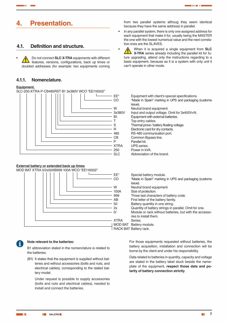
4.1.1. Nomenclature.Equipment.SLC-250-XTRA-P-CB485RST B1 3x380V WCO “EE116502”
External battery or extended back up timesMOD BAT XTRA 0/2x50AB999 100A WCO “EE116502”
EE* Equipment with client's special specifications.CO “Made in Spain” marking in UPS and packaging (customs
issue).W Neutral brand equipment.3x380V Input and output voltage. Omit for 3x400V+N.B1 Equipment with external batteries.T Top entry cables.S Thermal prove / battery floating voltage.R Electronic card for dry contacts.485 RS-485 communication port.CB Common Bypass line.P Parallel kit.XTRA UPS series.250 Power in kVA.SLC Abbreviation of the brand.
EE* Special battery module.CO “Made in Spain” marking in UPS and packaging (customs
issue).W Neutral brand equipment. 100A Size of protection.999 Three last characters of battery code.AB First letter of the battery family.50 Battery quantity in one string.2x Quantity of battery strings in parallel. Omit for one.0/ Module or rack without batteries, but with the accesso-
ries to install them.XTRA Series.MOD BAT Battery module.RACK BAT Battery rack.
Note relevant to the batteries:
B1 abbreviation stated in the nomenclature is related to the batteries:
(B1) It states that the equipment is supplied without bat-teries and without accessories (bolts and nuts, and electrical cables), corresponding to the stated bat-tery model.
Under request is possible to supply accessories (bolts and nuts and electrical cables), needed to install and connect the batteries.
For those equipments requested without batteries, the battery acquisition, installation and connection will be borne by the client and under his responsibility.
Data related to batteries in quantity, capacity and voltage are stated in the battery label stuck beside the name-plate of the equipment, respect those data and po-larity of battery connection strictly.
8
MBCB
SBCB
BCB
OCB
RCB
(R) (I)
(SSI)
(SB)
(T)
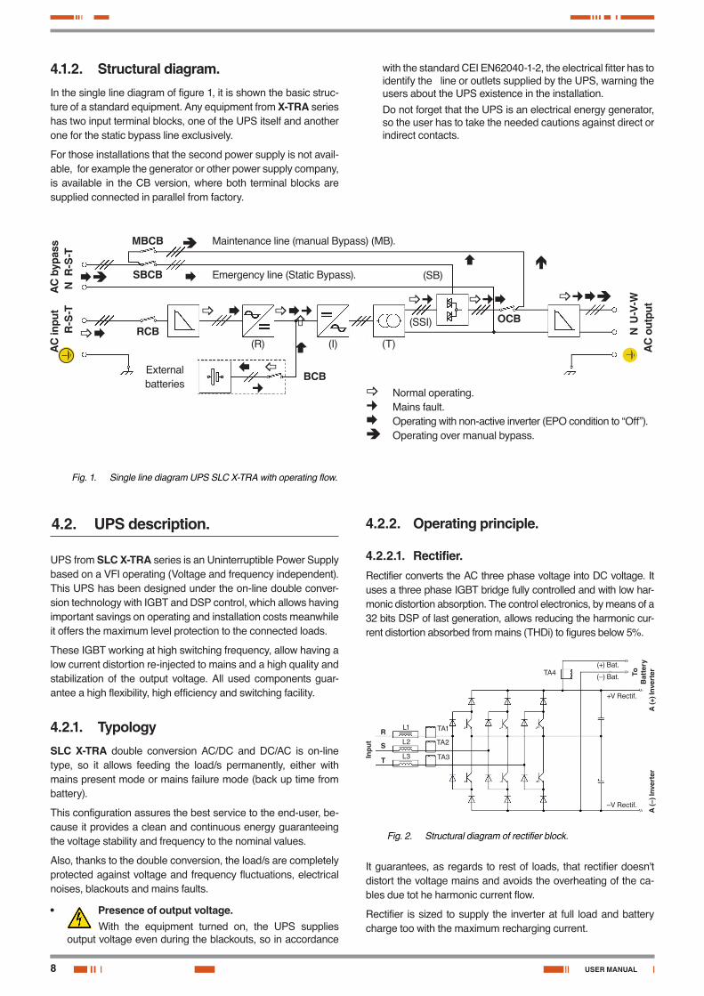
4.1.2. Structural diagram.In the single line diagram of figure 1, it is shown the basic struc-ture of a standard equipment. Any equipment from X-TRA series has two input terminal blocks, one of the UPS itself and another one for the static bypass line exclusively.
For those installations that the second power supply is not avail-able, for example the generator or other power supply company, is available in the CB version, where both terminal blocks are supplied connected in parallel from factory.
AC
inpu
t
R
-S-T
AC
byp
ass
N R
-S-T
N U
-V-W
AC
out
put
Maintenance line (manual Bypass) (MB).
Emergency line (Static Bypass).
Normal operating. Mains fault. Operating with non-active inverter (EPO condition to “Off”). Operating over manual bypass.
Fig. 1. Single line diagram UPS SLC X-TRA with operating flow.
4.2. UPS description.
UPS from SLC X-TRA series is an Uninterruptible Power Supply based on a VFI operating (Voltage and frequency independent). This UPS has been designed under the on-line double conver-sion technology with IGBT and DSP control, which allows having important savings on operating and installation costs meanwhile it offers the maximum level protection to the connected loads.
These IGBT working at high switching frequency, allow having a low current distortion re-injected to mains and a high quality and stabilization of the output voltage. All used components guar-antee a high flexibility, high efficiency and switching facility.
4.2.1. TypologySLC X-TRA double conversion AC/DC and DC/AC is on-line type, so it allows feeding the load/s permanently, either with mains present mode or mains failure mode (back up time from battery).
This configuration assures the best service to the end-user, be-cause it provides a clean and continuous energy guaranteeing the voltage stability and frequency to the nominal values.
Also, thanks to the double conversion, the load/s are completely protected against voltage and frequency fluctuations, electrical noises, blackouts and mains faults.
• Presence of output voltage.With the equipment turned on, the UPS supplies
output voltage even during the blackouts, so in accordance
with the standard CEI EN62040-1-2, the electrical fitter has to identify the line or outlets supplied by the UPS, warning the users about the UPS existence in the installation.
Do not forget that the UPS is an electrical energy generator, so the user has to take the needed cautions against direct or indirect contacts.
4.2.2. Operating principle.
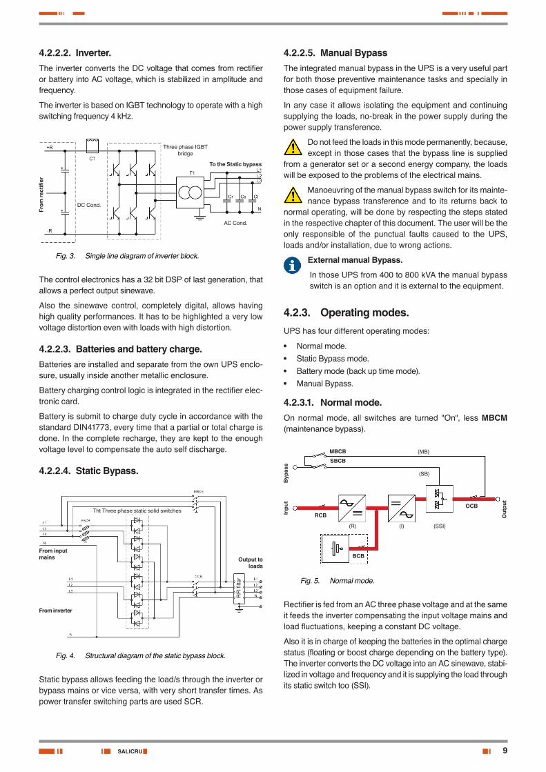
4.2.2.1. Rectifier.Rectifier converts the AC three phase voltage into DC voltage. It uses a three phase IGBT bridge fully controlled and with low har-monic distortion absorption. The control electronics, by means of a 32 bits DSP of last generation, allows reducing the harmonic cur-rent distortion absorbed from mains (THDi) to figures below 5%.
Inpu
t
R
S
T
TA1
TA2
TA3
+V Rectif.
A (+
) Inv
erte
rA
(–) I
nver
ter
To
Bat
tery(+) Bat.
(–) Bat.
–V Rectif.
TA4
L1
L2
L3
Fig. 2. Structural diagram of rectifier block.
It guarantees, as regards to rest of loads, that rectifier doesn't distort the voltage mains and avoids the overheating of the ca-bles due tot he harmonic current flow.
Rectifier is sized to supply the inverter at full load and battery charge too with the maximum recharging current.
External batteries
USER MANUAL
9SALICRU
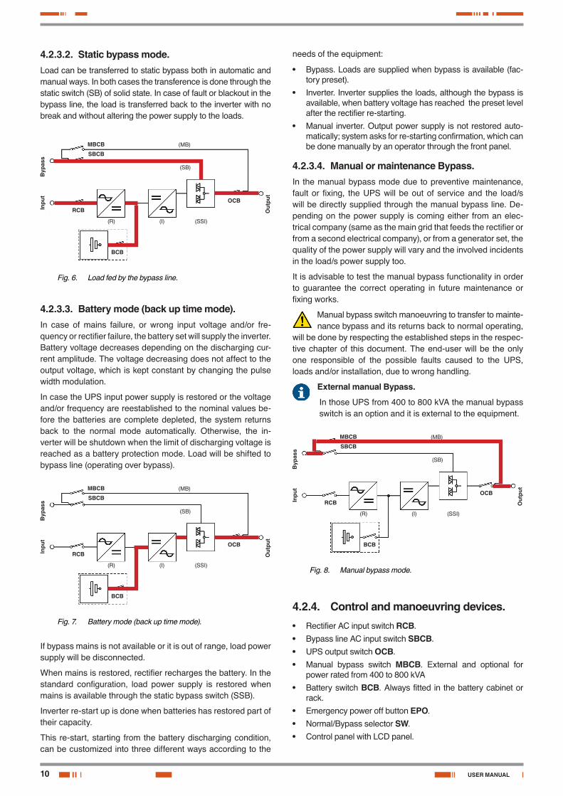
4.2.2.2. Inverter.The inverter converts the DC voltage that comes from rectifier or battery into AC voltage, which is stabilized in amplitude and frequency.
The inverter is based on IGBT technology to operate with a high switching frequency 4 kHz.
DC Cond.
Three phase IGBT bridge
From
rect
ifier
To the Static bypass
AC Cond.
Fig. 3. Single line diagram of inverter block.
The control electronics has a 32 bit DSP of last generation, that allows a perfect output sinewave.
Also the sinewave control, completely digital, allows having high quality performances. It has to be highlighted a very low voltage distortion even with loads with high distortion.
4.2.2.3. Batteries and battery charge.Batteries are installed and separate from the own UPS enclo-sure, usually inside another metallic enclosure.
Battery charging control logic is integrated in the rectifier elec-tronic card.
Battery is submit to charge duty cycle in accordance with the standard DIN41773, every time that a partial or total charge is done. In the complete recharge, they are kept to the enough voltage level to compensate the auto self discharge.
4.2.2.4. Static Bypass.
RFI
filte
r
Output to loads
From input mains
From inverter
Tht Three phase static solid switches
Fig. 4. Structural diagram of the static bypass block.
Static bypass allows feeding the load/s through the inverter or bypass mains or vice versa, with very short transfer times. As power transfer switching parts are used SCR.
4.2.2.5. Manual BypassThe integrated manual bypass in the UPS is a very useful part for both those preventive maintenance tasks and specially in those cases of equipment failure.
In any case it allows isolating the equipment and continuing supplying the loads, no-break in the power supply during the power supply transference.
Do not feed the loads in this mode permanently, because, except in those cases that the bypass line is supplied
from a generator set or a second energy company, the loads will be exposed to the problems of the electrical mains.
Manoeuvring of the manual bypass switch for its mainte-nance bypass transference and to its returns back to
normal operating, will be done by respecting the steps stated in the respective chapter of this document. The user will be the only responsible of the punctual faults caused to the UPS, loads and/or installation, due to wrong actions.
External manual Bypass.
In those UPS from 400 to 800 kVA the manual bypass switch is an option and it is external to the equipment.
4.2.3. Operating modes.UPS has four different operating modes:
• Normal mode.
• Static Bypass mode.
• Battery mode (back up time mode).
• Manual Bypass.
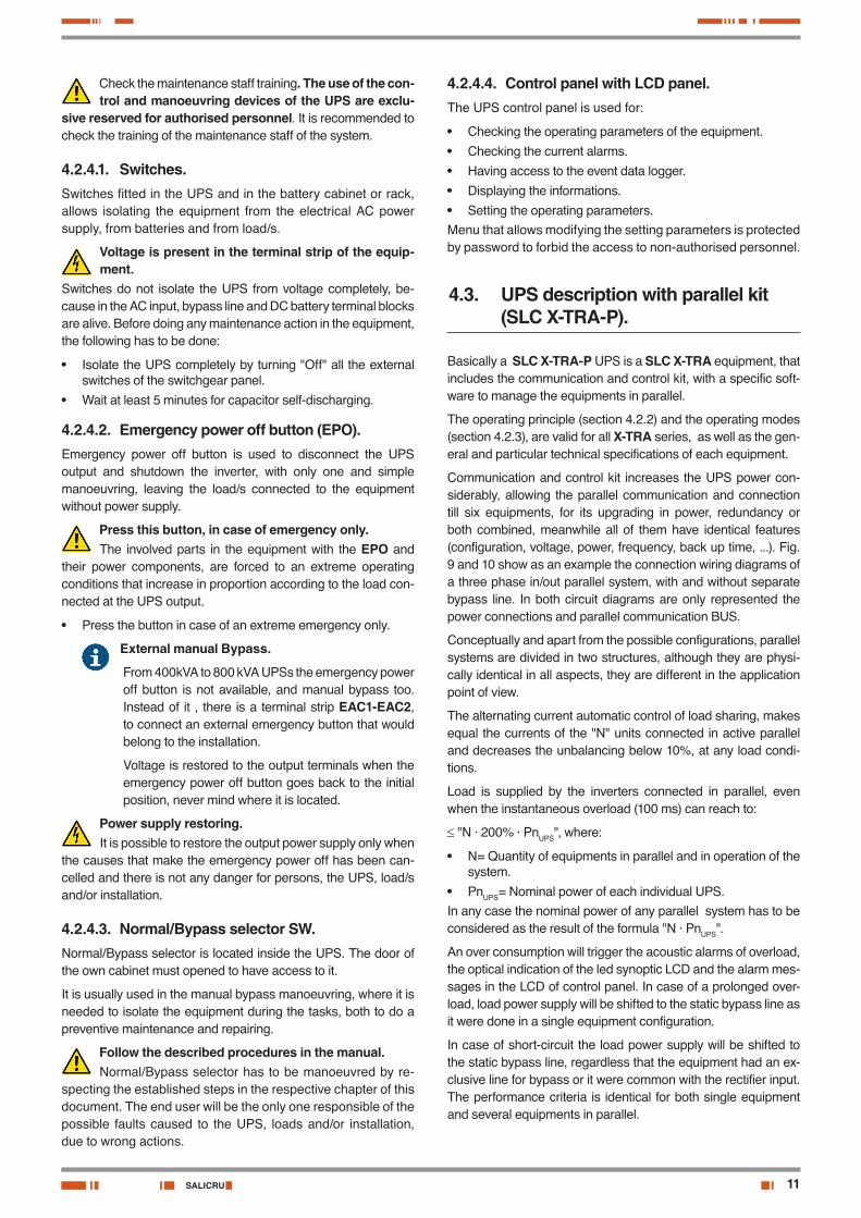
4.2.3.1. Normal mode.On normal mode, all switches are turned "On", less MBCM (maintenance bypass).
MBCB
SBCB
RCB
BCB
OCB
(MB)
(SB)
(SSI)(I)(R)
Byp
ass
Inpu
t
Out
put
Fig. 5. Normal mode.
Rectifier is fed from an AC three phase voltage and at the same it feeds the inverter compensating the input voltage mains and load fluctuations, keeping a constant DC voltage.
Also it is in charge of keeping the batteries in the optimal charge status (floating or boost charge depending on the battery type). The inverter converts the DC voltage into an AC sinewave, stabi-lized in voltage and frequency and it is supplying the load through its static switch too (SSI).
10
4.2.3.2. Static bypass mode.Load can be transferred to static bypass both in automatic and manual ways. In both cases the transference is done through the static switch (SB) of solid state. In case of fault or blackout in the bypass line, the load is transferred back to the inverter with no break and without altering the power supply to the loads.
MBCB
SBCB
RCB
BCB
OCB
(MB)
(SB)
(SSI)(I)(R)
Byp
ass
Inpu
t
Out
put
Fig. 6. Load fed by the bypass line.
4.2.3.3. Battery mode (back up time mode).In case of mains failure, or wrong input voltage and/or fre-quency or rectifier failure, the battery set will supply the inverter. Battery voltage decreases depending on the discharging cur-rent amplitude. The voltage decreasing does not affect to the output voltage, which is kept constant by changing the pulse width modulation.
In case the UPS input power supply is restored or the voltage and/or frequency are reestablished to the nominal values be-fore the batteries are complete depleted, the system returns back to the normal mode automatically. Otherwise, the in-verter will be shutdown when the limit of discharging voltage is reached as a battery protection mode. Load will be shifted to bypass line (operating over bypass).
MBCB
SBCB
RCB
BCB
OCB
(MB)
(SB)
(SSI)(I)(R)
Byp
ass
Inpu
t
Out
put
Fig. 7. Battery mode (back up time mode).
If bypass mains is not available or it is out of range, load power supply will be disconnected.
When mains is restored, rectifier recharges the battery. In the standard configuration, load power supply is restored when mains is available through the static bypass switch (SSB).
Inverter re-start up is done when batteries has restored part of their capacity.
This re-start, starting from the battery discharging condition, can be customized into three different ways according to the
needs of the equipment:
• Bypass. Loads are supplied when bypass is available (fac-tory preset).
• Inverter. Inverter supplies the loads, although the bypass is available, when battery voltage has reached the preset level after the rectifier re-starting.
• Manual inverter. Output power supply is not restored auto-matically; system asks for re-starting confirmation, which can be done manually by an operator through the front panel.
4.2.3.4. Manual or maintenance Bypass.In the manual bypass mode due to preventive maintenance, fault or fixing, the UPS will be out of service and the load/s will be directly supplied through the manual bypass line. De-pending on the power supply is coming either from an elec-trical company (same as the main grid that feeds the rectifier or from a second electrical company), or from a generator set, the quality of the power supply will vary and the involved incidents in the load/s power supply too.
It is advisable to test the manual bypass functionality in order to guarantee the correct operating in future maintenance or fixing works.
Manual bypass switch manoeuvring to transfer to mainte-nance bypass and its returns back to normal operating,
will be done by respecting the established steps in the respec-tive chapter of this document. The end-user will be the only one responsible of the possible faults caused to the UPS, loads and/or installation, due to wrong handling.
External manual Bypass.
In those UPS from 400 to 800 kVA the manual bypass switch is an option and it is external to the equipment.
MBCB
SBCB
RCB
BCB
OCB
(MB)
(SB)
(SSI)(I)(R)
Byp
ass
Inpu
t
Out
put
Fig. 8. Manual bypass mode.
4.2.4. Control and manoeuvring devices.• Rectifier AC input switch RCB.
• Bypass line AC input switch SBCB.
• UPS output switch OCB.
• Manual bypass switch MBCB. External and optional for power rated from 400 to 800 kVA
• Battery switch BCB. Always fitted in the battery cabinet or rack.
• Emergency power off button EPO.
• Normal/Bypass selector SW.
• Control panel with LCD panel.
USER MANUAL
11SALICRU
Check the maintenance staff training. The use of the con-trol and manoeuvring devices of the UPS are exclu-
sive reserved for authorised personnel. It is recommended to check the training of the maintenance staff of the system.
4.2.4.1. Switches.Switches fitted in the UPS and in the battery cabinet or rack, allows isolating the equipment from the electrical AC power supply, from batteries and from load/s.
Voltage is present in the terminal strip of the equip-ment.
Switches do not isolate the UPS from voltage completely, be-cause in the AC input, bypass line and DC battery terminal blocks are alive. Before doing any maintenance action in the equipment, the following has to be done:
• Isolate the UPS completely by turning "Off" all the external switches of the switchgear panel.
• Wait at least 5 minutes for capacitor self-discharging.
4.2.4.2. Emergency power off button (EPO).Emergency power off button is used to disconnect the UPS output and shutdown the inverter, with only one and simple manoeuvring, leaving the load/s connected to the equipment without power supply.
Press this button, in case of emergency only.The involved parts in the equipment with the EPO and
their power components, are forced to an extreme operating conditions that increase in proportion according to the load con-nected at the UPS output.
• Press the button in case of an extreme emergency only.
External manual Bypass.
From 400kVA to 800 kVA UPSs the emergency power off button is not available, and manual bypass too. Instead of it , there is a terminal strip EAC1-EAC2, to connect an external emergency button that would belong to the installation.
Voltage is restored to the output terminals when the emergency power off button goes back to the initial position, never mind where it is located.
Power supply restoring.It is possible to restore the output power supply only when
the causes that make the emergency power off has been can-celled and there is not any danger for persons, the UPS, load/s and/or installation.
4.2.4.3. Normal/Bypass selector SW.Normal/Bypass selector is located inside the UPS. The door of the own cabinet must opened to have access to it.
It is usually used in the manual bypass manoeuvring, where it is needed to isolate the equipment during the tasks, both to do a preventive maintenance and repairing.
Follow the described procedures in the manual.Normal/Bypass selector has to be manoeuvred by re-
specting the established steps in the respective chapter of this document. The end user will be the only one responsible of the possible faults caused to the UPS, loads and/or installation, due to wrong actions.
4.2.4.4. Control panel with LCD panel.The UPS control panel is used for:
• Checking the operating parameters of the equipment.
• Checking the current alarms.
• Having access to the event data logger.
• Displaying the informations.
• Setting the operating parameters.Menu that allows modifying the setting parameters is protected by password to forbid the access to non-authorised personnel.
4.3. UPS description with parallel kit (SLC X-TRA-P).
Basically a SLC X-TRA-P UPS is a SLC X-TRA equipment, that includes the communication and control kit, with a specific soft-ware to manage the equipments in parallel.
The operating principle (section 4.2.2) and the operating modes (section 4.2.3), are valid for all X-TRA series, as well as the gen-eral and particular technical specifications of each equipment.
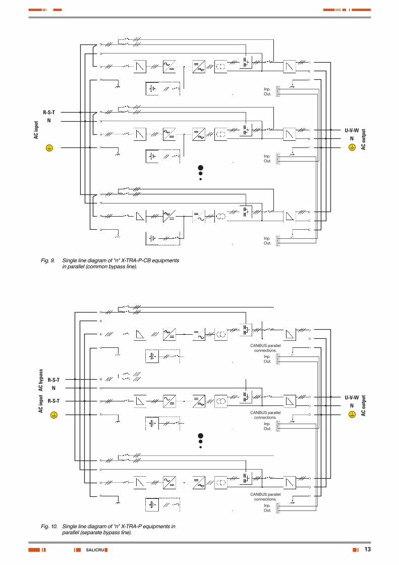
Communication and control kit increases the UPS power con-siderably, allowing the parallel communication and connection till six equipments, for its upgrading in power, redundancy or both combined, meanwhile all of them have identical features (configuration, voltage, power, frequency, back up time, ...). Fig. 9 and 10 show as an example the connection wiring diagrams of a three phase in/out parallel system, with and without separate bypass line. In both circuit diagrams are only represented the power connections and parallel communication BUS.
Conceptually and apart from the possible configurations, parallel systems are divided in two structures, although they are physi-cally identical in all aspects, they are different in the application point of view.
The alternating current automatic control of load sharing, makes equal the currents of the "N" units connected in active parallel and decreases the unbalancing below 10%, at any load condi-tions.
Load is supplied by the inverters connected in parallel, even when the instantaneous overload (100 ms) can reach to:
≤ "N · 200% · PnUPS", where:
• N= Quantity of equipments in parallel and in operation of the system.
• PnUPS= Nominal power of each individual UPS.In any case the nominal power of any parallel system has to be considered as the result of the formula "N · PnUPS".
An over consumption will trigger the acoustic alarms of overload, the optical indication of the led synoptic LCD and the alarm mes-sages in the LCD of control panel. In case of a prolonged over-load, load power supply will be shifted to the static bypass line as it were done in a single equipment configuration.
In case of short-circuit the load power supply will be shifted to the static bypass line, regardless that the equipment had an ex-clusive line for bypass or it were common with the rectifier input. The performance criteria is identical for both single equipment and several equipments in parallel.
12
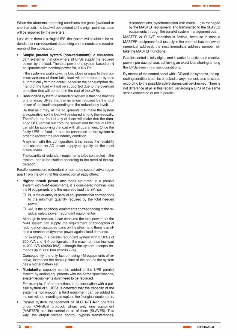
When the abnormal operating conditions are gone (overload or short-circuit), the load will be restored to the origin point, so loads will be supplied by the inverters.
Less when there is a single UPS, the system will be able to be re-dundant or non-redundant depending on the needs and require-ments of the application.
• Simple parallel system (non-redundant): a non-redun-dant system is that one where all UPSs supply the required power by the load. The total power of a system based on N equipments with nominal power Pn, is N x Pn.
If the system is working with a load close or equal to the max-imum and one of them fails, load will be shifted to bypass automatically with no-break, because the consumption de-mand of the load will not be supported due to the overload condition that will be done in the rest of the UPSs.
• Redundant system: a redundant system is that one that has one or more UPSs that the minimum required by the total power of the load/s (depending on the redundancy level).
Be that as it may, all the equipments that make the system are operative, so the load will be shared among them equally. Therefore, the fault of any of them will make that the dam-aged UPS remain out from the system and the rest of UPSs can still be supplying the load with all guarantees. Once the faulty UPS is fixed , it can be connected to the system in order to recover the redundancy condition.
A system with this configuration, it increases the reliability and assures an AC power supply of quality for the most critical loads.
The quantity of redundant equipments to be connected in the system, has to be studied according to the need of the ap-plication.
Parallel connection, redundant or not, adds several advantages apart from the own that this connection already offers:
• Higher inrush power and back up time: in a parallel system with N+M equipments, it is considered nominal load the N equipments and the reserved load the +M, so:
� N, is the quantity of parallel equipments that corresponds to the minimum quantity required by the total needed power.
� +M, is the additional equipments corresponding to the re-sidual safety power (redundant equipments).
Although in practice, it can consume the total power that the N+M system can supply, the requirement or conception of redundancy dissuades it and on the other hand there is avail-able a remnant of dynamic power against load demands.
For example, in a parallel redundant system with 3 UPSs of 200 kVA and N+1 configuration, the maximum nominal load is 400 kVA (2x200 kVA), although the system accepts de-mands up to 600 kVA (3x200 kVA).
Consequently, the only fact of having +M equipments of re-serve, increases the back up time of the set, as the system has a higher battery set.
• Modularity: capacity can be added to the UPS parallel system by adding equipments with the same specifications, existent equipments don't need to be replaced.
For example, if after sometime, in an installation with a par-allel system of 2 UPSs is detected that the capacity of the system is not enough, a third equipment can be added to the set, without needing to replace the 2 original equipments.
• Parallel system management of SLC X-TRA-P operates under CANBUS protocol, where only one equipment (MASTER) has the control of all of them (SLAVES). This way, the output voltage control, bypass transferences,
disconnections, synchronisation with mains, ...; is managed by the MASTER equipment, and transmitted to the SLAVES equipments through the parallel system management bus.
MASTER or SLAVE condition is flexible, because in case a MASTER equipment fault (usually is the one that has the lowest numerical address), the next immediate address number will take the MASTER functions.
Parallel control is fully digital and it works for active and reactive powers per each phase, achieving an exact load sharing among the UPSs even in transient conditions.
By means of the control panel with LCD and led synoptic, the op-erating conditions can be checked at any moment, also its status according to the possible active alarms can be checked. There is not difference at all in this regard, regarding a UPS of the same series connected or not in parallel.
USER MANUAL
13SALICRU
Fig. 9. Single line diagram of "n" X-TRA-P-CB equipments in parallel (common bypass line).
AC
outp
utU-V-W
N
AC
inpu
t
R-S-T
N
Inp.Out.
Inp.Out.
Inp.Out.
AC
outp
utU-V-W
N
AC
inpu
tA
C by
pass
R-S-T
R-S-T
N
Inp.Out.
CANBUS parallel connections.
Inp.Out.
Inp.Out.
CANBUS parallel connections.
CANBUS parallel connections.
Fig. 10. Single line diagram of "n" X-TRA-P equipments in parallel (separate bypass line).

14
5. Installation.
• It is compulsory the compliance in terms of the safety instructions, being the legal responsible the user re-
garding to its observance. Read carefully them and follow the stated steps in the established order. The local electrical regulations and the different restrictions of the user's loca-tion, can invalidate some recommendations included in the manuals. When discrepancies exist, the user has to comply the local regulations.
• The purpose of this manual is to provide the explanations and procedures for the installation and operating of the equipment. Before installing and using the equipment, be sure that the instructions included in this manual an the rest of the support documentation have been read.
If the instructions in the supplied documentation are not total or partial understood, do not continue with the installation and operation tasks, because it could
be a risk for your safety and even for the other people, apart from the own equipment and/or loads and installation.
• Manual and technical support documents are relating to the product, so they have to be kept close to the equipment in an accessible place. In case of loosing them, ask for a docu-mentation duplicate.
• Check that all nameplate data are the required for the instal-lation.
• A wrong connection or manoeuvring, can make faults in the UPS and/or loads connected to itself. Read carefully the in-structions of this manual and follow the stated steps in the established order.
• This UPS has to be installed and used by qualified per-sonnel only.
Any intervention in the UPS by personnel with no specific preparation, means an electrical shock risk, besides of possible injuries to third persons,
UPS or loads and/or installation faults.
Any person is defined as qualified, if he has experience in assembling, starting up and control the correct operating of the equipment, if he has the requirements to make the work and if he has read and understood all the written in this manual, and in particular the safety instructions. Such preparation is only considered valid, if it is certified by our company.
• Do not connect in parallel equipments from SLC X-TRA with different features, versions, configura-
tions, back up times or duplicated addresses (like two equip-ments that although they are identical has the same address because they belong to two different parallel systems).
• In any parallel system there is only one assigned address for each one of the equipments that makes it, being the MASTER the one with the lowest numerical range and the next correlative numbers the SLAVES.
• When acquiring only one equipment from SLC X-TRA series with parallel kit, foreseen for future upgrading,
only the instructions relating to the basic equipment will be attended, because it can't operate in another mode because it is an installation with only one equipment.
• It is advisable and very useful, not to say essential, to equip the parallel system installation, with a panel with separate protections for input, output and static bypass (the last one will not be needed for those equipments with common line for bypass and input), besides a manual bypass. Protection panel allows isolating only one equipment from the parallel
system, against any fault and supply the loads with the rest ones during its preventive maintenance or fixing.
• An external manual bypass panel for a single unit or parallel system can be purchased under request.
Also, it can be manufactured by yourself by keeping in mind the version and configuration of the available equipment or system and the attached documentation in the CD-ROM as regards to «Recommended installation diagram».
• In parallel systems, cable length and cross cable sec-tion for any UPS from the protection panel to itself
and vice versa will be the same for anyone without any ex-ception.
5.1. Important safety instructions.
• As this is a device with class I protection against electric shocks, it is essential to install a protective
earth conductor ( ). Connect the conductor, before con-necting the power supply to UPS input
• The distribution panel will have installed a residual current device from 300 to 500 mA sized to the suitable power of the system. When the input and bypass lines are common, the RCD device will be common for both lines. This premise will be applied for equipments in redundancy connection too.
• All connections in the equipment, including those for con-trol (interface, remote control, ...), will be performed with the switches at rest and without any mains present (UPS power line input switch and those equipments with separate by-pass line the bypass switch to "Off").
• Do not forget that the UPS is an electrical generator, so users must take all necessary precautions against direct or indirect contacts.
• The equipments have adhesive labels with indications for risks; these labels have to be visible and replaced in case of damaging.
• Warning labels should be placed on all primary power switches installed in places away from the equipment to alert the electrical maintenance personnel of the presence of a UPS in the circuit.
• The label will bear the following text or an equivalent one:
Before working in this circuit.
• Isolate the Uninterruptible Power System (UPS).
• Check the voltage between all terminals including the protective earth.
Risk of voltage feedback from UPS.
• When supplying voltage to a UPS of this series, consider that although the inverter is turned «Off» (deactivated) it doesn't mean that there is not any voltage in the output terminal strip, because these equipments always have static bypass line, separate or common to the rectifier line.
To break the output power supply completely, turn the switches RCB, SBCB and OCB to «Off» position.
Also, it is possible that the UPS might be supplying output voltage through the manual bypass, so this must be considered for the purpose of safety. If the output power supply of the UPS has to be interrupted in this situation, deactivate the switch MBCB. For models higher than 300 kVA, the equipment does not incorporate this manual bypass switch and it is only possible to acquire it as an option for its external installation to UPS enclosure.
USER MANUAL
15SALICRU
• Inside the UPS there are dangerous voltages, never open the cabinet, the access has to be done by authorised and competent personnel. In case of maintenance or fault, con-sult the closest (S.T.S.).
• Cross cable sections used to supply the equipment and loads must be accordingly to the nominal current stated in the nameplate stuck in the equipment, by respecting the Low Voltage Electrotechnical Regulation.
• All power supply electrical cables of the equipments and loads, interfaces, etc, have to be fixed to immovable parts, otherwise they will be exposed to wrenches.
• Take care with the battery terminals because they are not isolated from the AC input line, existing the risk of dangerous voltage between the battery and earth terminals.
• In an optimal installation, the battery cabinet/s will be in-stalled as close to the equipment as possible, but respecting the minimum peripheral distanced stated in section 5.3.4, this way the cable length of the DC voltage connection will be reduced and consequently the dropping voltage losses should be kept in mind due to the importance of the battery operating during the mains failures, although they are mini-mised.
Logically in the parallel systems, the equipments and their battery cabinets will be arranged attending the premises stated in the previous paragraph to this point.
• In order to avoid a total discharge of the batteries and as a safety measure after a long power supply break and when ending the working day, loads and equipment has to be shut-down by following the described operation.
• For long period of time of disconnection, consider the con-nection of the equipment once per month for ten hours as minimum, in order to recharge the batteries, avoiding the irre-versible degradation of them. On the other hand, the storage will be done in a fresh and dry place, never outdoor.
5.1.1. Safety instructions regarding to batteries.
• The manipulation and connection of the batteries shall be done and supervised by personnel with battery knowledge only.
• Batteries themselves, are supplied separate from the me-tallic cabinet, among other reasons, is because the cabinet is designed to store the batteries but not to support the me-chanical efforts linked to the transport.
Once the location of the equipment and battery cabinet/s is finished and always respecting the indications stated in this document, proceed to fit the batteries in the own cabinet and to make their internal connection, following the supplied diagram inside the own battery cabinet together with rest of the auxiliary parts like bolts and nuts, cables or connection copper bars.
Only personnel with battery and/or DC voltage knowl-edge, is authorised to make or supervise the connec-
tion of them. It is very dangerous to make these works without the needed training.
There is a high risk of electrical discharge with serious or very serious consequences even the death.
• For units requested without batteries, the acquisition, in-stallation and connection of the batteries will always be done by the customer and under his responsibilty. The relative data to the batteries as far as number, capacity and voltage are indicated in the battery label stuck beside
the nameplate of the equipment, respect these data strictly, the battery polarity connection and the circuit diagram pro-vided with this documentation.
Only personnel with battery and/or DC voltage knowl-edge, is authorised to make or supervise the connec-
tion of them. It is very dangerous to make these works without the needed training.
There is a high risk of electrical discharge with serious or very serious consequences even the death.
• The battery voltage can involve the risk of electric shock and can produce high short circuit currents. Observe the following preventive measures before manipulating any terminal block identified in the labelling as «Batteries».
� Disconnect the corresponding protection elements.
� When connecting a battery cabinet to the equipment, respect the cable’s polarity and colour (red-positive; black-negative) indicated in the manual and in the corresponding labelling.
� Wear rubber gloves and shoes.
� Use tools with insulated handles.
� Removes watches, rings or other metal objects.
� Do not place metal tools or objects on the batteries.
� Never manipulate with your hands or through conducting objects, do not short either the battery terminal block of the equipment or the battery enclosure.
• Never short the battery terminals as it involves a high risk. It involves the detriment of the equipment and batteries
• Avoid mechanical efforts and impacts.
• Do not open or mutilate the battery. Released electrolyte is harmful and toxic to the skin and eyes.
• Do not dispose the batteries in a fire and high temperatures. The batteries may explode.
• In case of contact of the acid with parts of the body, wash immediately with plenty water and call urgently the nearest medical service.
• Batteries involve a serious risk for the health and for the en-vironment. Their disposal should be done according to the existing laws.
5.1.2. Transport and handling.• During transport and handling of the product, pay attention to
the avoid bending or deforming parts and to change isolation distances.
• Weight is not distributed.UPS weight is not distributed uniformly. Pay attention
when transporting and location approaching handling, be-cause there is risk of dumping.
Before starting any handling movement, check that there is not any person in the vicinity. Consider
the serious consequences that an equipment dropping over a person could have and even the death in extreme cases due to crushing.
• On receiving the device, make sure that it has not suffered any damage in transport. In case of any doubt of the total integrity of the packaging or the internal product make all pertinent claims to the transport agency and/or distributor, and in their lack to our company, by quoting serial number and references in the delivery note. Claims have to be done in the following 6 days to the product reception and it is man-datory to inform to the transport agency, regardless of any other action.
16
Danger of injury due to mechanical faults.Mechanical faults of the electrical parts are a serious danger for the personnel, the own equipment, load/s
and installation. Do not make installation works and/or com-missioning, in case of detecting damages in the product.
• If it were necessary to return the equipment back, use the original packaging always.
• Once the reception is finished, it is suitable to pack the UPS again till its commissioning in order to protect it against me-chanical shocks, dust, dirt, etc...
5.1.3. Installation.• Installation of the product has to be done respecting the in-
dications of the technical support documentation, even the current safety indications.
It is essential to keep in mind the following points:
� This product has to be placed over a platform that can support the weight of the equipment and assure its ver-tical position;
� UPS has to be installed in an area with restricted access in accordance with the standard CEI EN 62040-1-2;
� Do not place the equipment close to liquids or in an envi-ronment with excessive humidity.
� Do not allow that liquid or objects enter inside the equip-ment.
� Do not cover the cooling grids.
� Avoid direct sunlight to the equipment and do not place it near to heat sources.
• Particular environment conditions.UPS is designed to support normal conditions of cli-
mate and environment, as the technical specifications state: altitude, operating ambient temperature, relative humidity, transport and storage environment conditions. It is neces-sary to take particular protection measures in case of unu-sual conditions:
� Harmful smoke, dust, abrasive dust.
� Humidity, vapour, saline air, bad weather of water filtering.
� Explosive vapour or gas mixture.
� Extreme variation temperature.
� Bad cooling.
� Conductor or radiant heat coming from other sources.
� Powerful electromagnetic fields.
� Higher radioactive levels than in the environment.
� Fungus, vermin, parasites, etc.
• Use by authorised personnel only.All transport, installation and commissioning opera-
tions have to be done by qualified and trained personnel.
UPS installation has to be done in accordance with the local and national regulations on the part of the authorised per-sonnel.
• Do not modify the equipment.Do not make any modification in the equipment, be-
cause it could cause failures in itself, injuries to third persons or yourself, load/s failures and/or in the installation.
Maintenance and fixing has to be done by authorised personnel only. Contact with our company or search through our website the nearest Service and Technical Support point (S.T.S.).
5.1.4. Electrical connection.• The connection of the UPS to mains has to be done by re-
specting the current regulation.
• Check the data in the nameplate are the required ones by the installation.
• Check the conformity of the documentation.UPS has to be installed in accordance with the regula-
tions of HD 384.4.42 S1/A2 and the standard CEI 60364-4-482 - chapter 482: fire protection.
Before doing the connection to mains, make sure that you have the approval from the electrical energy distribution to do it, in accordance with the current national regulations.
All connections have to be done by qualified personnel; be-fore connecting the equipment, check that:
� AC mains connection cables have the corresponding protection (fuses or circuit breaker switch).
� Nominal, frequency and phase rotation from AC power supply is the suitable one.
� Polarity connection between UPS and battery cabinet is correct.
� The possible earth dispersion has been controlled.
• UPS is connected to the following power supplies:
� Battery DC voltage.
� Mains AC voltage.
� Bypass AC voltage.
• Danger of injuries due to electrical shock.The equipment is exposed to high voltages, so it is important to follow the safety directives before doing
any work over the UPS:
� Connect the earth conductor to its terminal or bar, before doing any other connection.
� Disconnect the battery switch or any other protection ele-ment, before manipulating and/or connecting the cables to the UPS.
• Danger of injuries due to electrical shock.If the input switch has been fitted in an different area from the UPS, put the following label in a visible place
about the equipment:
Before working in the circuit.
- Isolate the Uninterruptible Power Supply (UPS).
5.1.5. Operating.• Installations were the UPS belongs to, have to meet all the
current safety regulations (technical staff and safety practice at work). This device has to be commissioned, manipulated and disconnected by authorised personnel only.
• Calibration settings can only be changed by using the orig-inal software.
• Danger of injuries due to electrical shock.During the operation, energy conversions are made
inside the equipment, which mean the presence of high voltage and currents.
� Before start up the equipment, check that all covers and door are closed.
• Danger due to toxic substances contact.The supplied batteries with the UPS content a small
USER MANUAL
17SALICRU
quantity of toxic substances. Nevertheless and to avoid ac-cidents, follow the following rules:
� Do not turn ON the UPS if the temperature and humidity levels exceed the established limits in the technical spec-ifications.
� Do not put the batteries in contact with the fire (risk of explosion).
� Do not open the battery (released electrolyte is harmful to the skin and eyes).
� Batteries involve a serious risk for the health and for the environment, their disposal should be done according to the existing laws.
5.1.6. Maintenance.• Maintenance and fixing tasks are reserved for authorised
and qualified personnel only. Before doing any action relating to this tasks check that the UPS is completely disconnected from AC mains (input power supply) and DC (batteries).
• Even disconnecting all the internal switches of the equipment, there is voltage at the AC input terminal block. To isolate the UPS completely, it is necessary to install external switches at the input and bypass lines.
• Also, after turning off and the possible disconnection from the AC power supply, inside the equipment there are dan-gerous voltages due to the slow discharge of the capacitors. It is better to wait for 5 minutes as minimum before opening the UPS doors.
• Danger of injuries due to electrical shock.The possible interventions inside the equipment can
only de done in case of lack of voltage and by respecting the safety regulations:
� Check that the battery switch, usually located in the same cabinet or rack, is turned "Off".
� Isolate the equipment completely by turning the external switches of the AC lines (input and bypass).
� Wait for 5 minutes as minimum, to discharge the capaci-tors.
• High temperature of some components.After shutdown and disconnecting the UPS some
components could be very hot (transformers, heatsinks, etc), it is advised to use protection gloves.
5.1.7. Storage.Keep the UPS into its original packaging, and dry place, safe-guard from rain, protected from dust and temperatures between –10°C a +70°C.
In the storage of the equipment, the particular protection meas-ures will be kept in mind in case of unusual conditions.
� Particular environment conditions.UPS is designed to support normal climatic and
environment conditions, as it is stated in the technical specifications: altitude, operating ambient temperature, relative humidity, transport and storage ambient condi-tions. It is necessary to take protection particular meas-ures in case of unusual conditions:
– Harmful smoke, dust, abrasive dust.
– Humidity, vapour, saline air, bad weather of water fil-tering.
– Explosive vapour or gas mixture.
– Extreme variation temperature.
– Bad cooling.
– Conductor or radiant heat coming from other sources.
– Powerful electromagnetic fields.
– Higher radioactive levels than in the environment.
– Fungus, vermin, parasites, etc.
5.2. To keep in mind.
• Do not install the equipment in corrosive, dusty environments and even outdoors.
• Do not obstruct the cooling grids by entering objects through themselves or other orifices.
• Leave space in the equipment peripheral for the air cooling flow (see section 5.3.5.).
• Location will be spacious, ventilated, far from heat sources and easy access.
• Place the equipment the closest to the power supply and loads to be supplied.
• Do not put materials over the equipment or parts that obstruct the correct visualization of the synoptic.
• Do not clean the equipments with abrasive, corrosive, liquids or detergent products. To clean the equipment, wipe over a damp cloth and then dry it. Avoid sprinkling or spillage that could enter through the slots or cooling grids.
• Avoid direct sunlight, because it contributes to increase the temperature of the equipment significantly and even more in summer months, where the impact will higher.
• All UPSs from SLC X-TRA series and the battery sets have terminal blocks as connection parts for power and connec-tors for communications, located inside the equipment.
� Open the front doors of the equipment to access to them.
� When connection tasks are ended, close the doors.
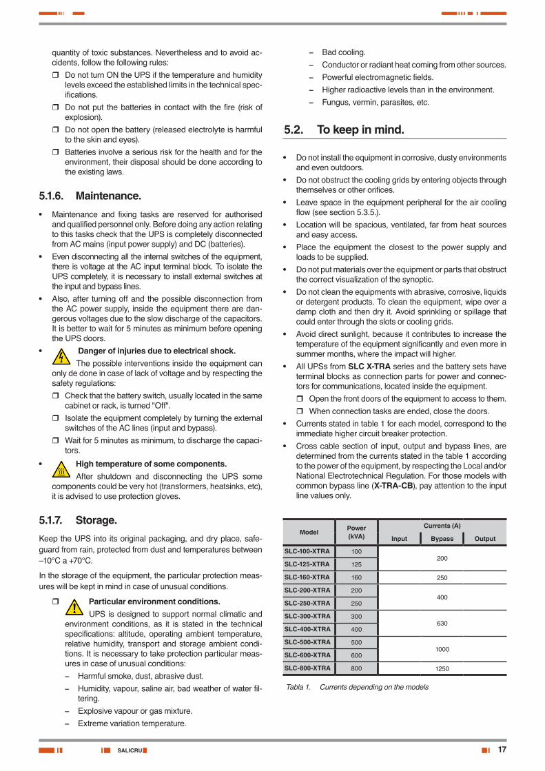
• Currents stated in table 1 for each model, correspond to the immediate higher circuit breaker protection.
• Cross cable section of input, output and bypass lines, are determined from the currents stated in the table 1 according to the power of the equipment, by respecting the Local and/or National Electrotechnical Regulation. For those models with common bypass line (X-TRA-CB), pay attention to the input line values only.
Model Power (kVA)
Currents (A)
Input Bypass Output
SLC-100-XTRA 100200
SLC-125-XTRA 125
SLC-160-XTRA 160 250
SLC-200-XTRA 200400
SLC-250-XTRA 250
SLC-300-XTRA 300630
SLC-400-XTRA 400
SLC-500-XTRA 5001000
SLC-600-XTRA 600
SLC-800-XTRA 800 1250
Tabla 1. Currents depending on the models
18
• The switchgear or external manual bypass panel:
� At least, the installation will have one protection for the short-circuit in the power supply line of the UPS.
� For single equipments, it is recommended to install an external manual bypass panel, equipped with input, output and manual bypass protections.
� For parallel systems, it is essential to install a switch-gear or manual bypass panel. The switches of the panel must allow isolating one UPS from the system, in case of any failure and allow feeding the loads with the rest ones, either during the preventive maintenance tasks or during the failure and its reparation.
• The documentation delivered together with this user's manual and/or CD-ROM or Pen Drive, includes infor-
mation regarding the «Recommended installation diagram» for each input and output configuration. This documentation shows the wiring circuit diagrams, as well as the protection and cross cable sizes that are connected to the equipment, considering the nominal voltage. All the figures are calcu-lated for a total maximum cable length of 30 m between the switchgear panel, equipment and loads.
� For longer lengths, correct the cross cable sections in accordance with the Regulations or standards of the country, in order to avoid dropping voltages.
� In the own documentation and for each configuration, it is available the information for «N» equipments in par-allel, as well as the features of the «Backfeed protec-tion» (for models up to 300 kVA).
• In parallel systems, the length and cross cable sec-tion that connect the switchgear or manual bypass
panel with each UPS must be the same for all of them, with no exception.
• The cross cable section must be always according to the size of the own terminals of the switches, in such way that the wire is embraced properly, in order to guarantee an op-timal contact between both parts.
• In the nameplate of the equipment, it has only printed the nom-inal currents as it states the safety regulation EN-IEC 62040-1. To calculate the input current, it has been considered the power factor and the own efficiency of the equipment.
It is better to install protections and cross sections according to the currents in table 1.
Overload conditions is considered as a nonpermanent and exceptional mode.
• If it is added peripherals to the input, output or bypass like trans-formers or autotransformers to the UPS, the currents stated in the own nameplates of those elements has to be considered in order to use the suitable cross sections, by respecting the Local and/or National Low Voltage Regulation.
• When an equipment incorporates a galvanic isolation trans-former, as standard, as an option or either installed by your-self, either at the UPS input, bypass line, output or at all of them, protections against indirect contact has to be fitted in (residual current device) at the output of each transformer, because its specification of isolation will prevent the trig-gering of the protections fitted in the primary of the trans-former in case of electrical shock in the secondary (output of the isolation transformer).
• Remind you that all external isolation transformers and sup-plied from factory to be installed at the output, has the neutral of the secondary connected to earth by means of a cable bridge between both terminals. If it were required an isolated output neutral, remove this cable bridge, keeping the precau-tions stated in the respective local and/or national low voltage regulations.
• Input entry cable is foreseen through the bottom.
• Batteries are always installed in one or more cabinets, or in a particular rack under request, but they are always separate from the own UPS cabinet.
Only personnel with battery and/or DC voltage knowl-edge, is authorised to make or supervise the connec-tion of them. It is very dangerous to make these works
without the needed training.
There is high risk of electrical discharge with serious or very serious consequences even the death.
Important for safety.Do not turn the battery switch BCB fitted in the
cabinet/s of the accumulators to “On” till it is indicated, be-cause irreversible damages can be done to the equipment, load/s, installation or even injuries to persons.
USER MANUAL
19SALICRU
Points to enter the forklift.
200 and 300 kVA models
Low
er fr
ont c
over
Separate the equipment through this point for shipping.
Points to enter the forklift.
400 kVA model. 500 and 600 kVA models.
Separate the equipment through this point for shipping.
Points to enter the forklift.
Separate the equipment through this point for shipping. Separate the equipment through this point for shipping.
Points to enter the forklift.
800 kVA model.
Points to enter the forklift.
Lo
wer
fron
t cov
er100 to 160 kVA models.
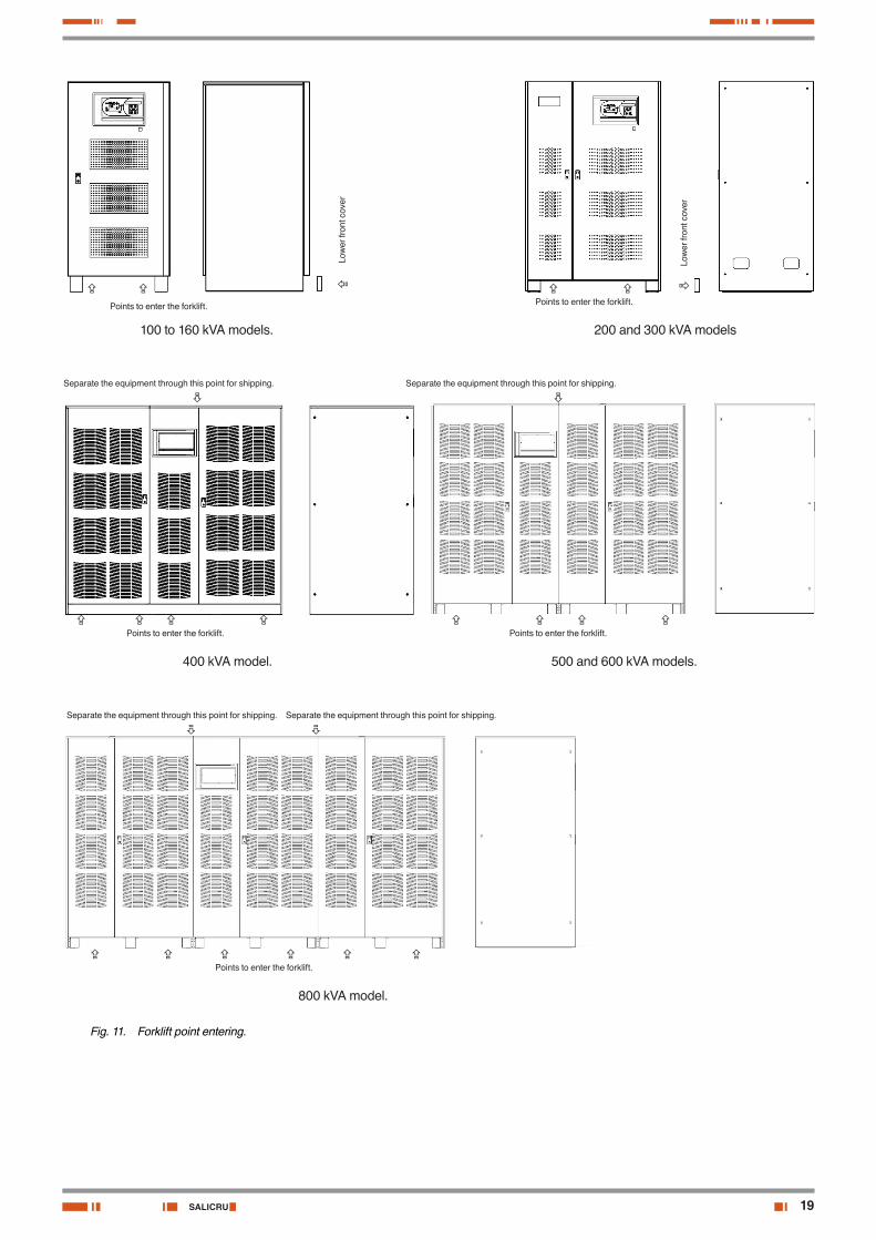
Fig. 11. Forklift point entering.
20
5.3. Reception of the equipment.
5.3.1. Unpacking and contents checking.• On receiving the device, make sure that it has not suffered
any damage in transport. In case of any doubt of the total integrity of the packaging or the internal product make all pertinent claims to the transport agency and/or distributor, and in their lack to our company, by quoting serial number and references in the delivery note. Claims have to be done in the following 6 days to the product reception and it is man-datory to inform to the transport agency, regardless of any other action
Danger of injury due to mechanical faults.Mechanical faults of the electrical parts are a serious danger for the personnel, the own equipment, load/s
and installation. Do not make installation works and/or com-missioning, in case of detecting damages in the product.
• Once the reception is finished, it is suitable to pack the UPS again till its commissioning in order to protect it against me-chanical shocks, dust, dirt, etc...
• The packaging of the device consists of a wooden pallet, a cardboard or wooden packing depending on the case, expanded polystyrene corner pieces, polyethylene sleeve and band, all of tham are recyclable materials; therefore they should be disposed according to current regulations. We recommend that the packaging should be kept in case its use is necessary in the future
• To unpack, cut the bands on the cardboard packing and take it out through the top as it were a cover or remove it with the necessary tools if the packing is made of wood; remove the corner pieces and the plastic sleeve. The UPS will be unpacked on the pallet, download it by using the suitable mediums an respecting the safety that it behaves; the ap-proximate weights of the table 2 must be considered.
5.3.2. Storage.
• Storage of the equipment will be done in a dry place, safe-guard from rain, protected from dust, water jets or chemical agents, never outdoors.
It is advisable to keep the equipment and the battery pack/s, into their original packages, which have been designed to as-sure the maximum protection during the transport and storage.
• In general and other than in special cases, the UPS has sealed VRLA batteries with 10 years lifetime and
should not be stored for more than 12 months (see the date of the last charge of the batteries, noted on the label adhered to the device packaging or on the battery cabinet)
After this time, install and interconnect the batteries among them in their battery cabinets or racks , according to the pro-vided circuit diagram with the documentation of the equipment. This operation is exclusive reserved to be done and super-vised by personnel with battery knowledge, or contact with the (S.T.S.) of our firm to make the corresponding operations.
Next connect the UPS with the battery pack/s to the mains, start it up according to the instructions described in this manual and charge the batteries for 2 hours from floating level.
Reached this point, shutdown the system, disconnect it from mains and from battery pack/s. Finally disconnect the bat-tery connections among batteries and fit them in their orig-inal packaging, noting the new battery charge date on each respective label.
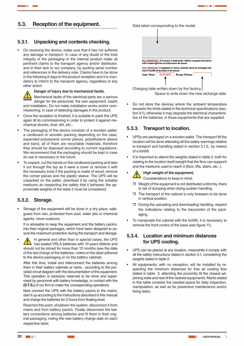
Charging date written down by the factory.Space to write down the new recharge date.
15-07-2013
Data label corresponding to the model.
• Do not store the devices where the ambient temperature exceeds the limits stated in the technical specifications (sec-tion 9.1), otherwise it may degrade the electrical characteris-tics of the batteries, in those equipments that are supplied.
5.3.3. Transport to location.
• UPSs are packaged on a wooden pallet. The transport till the location will be done attending all the safety warnings relative to transport and handling stated in section 5.1.2., by means of a forklift.
• It is important to attend the weights stated in table 2, both for relating to the location itself (weight that the floor can support) and the mediums used to reach it (floor, lifts, stairs, etc...).
• High weight of the equipment.Considerations to keep in mind:
� Weight of the equipment is not distributed uniformly, there is risk of dumping when doing sudden handling.
� The transport of the cabinet is only foreseen to be done in vertical position.
� During the uploading and downloading handling, respect the indications relating to the barycentre of the pack-aging.
• To manipulate the cabinet with the forklift, it is necessary to remove the front covers of the base (see figure 11).
5.3.4. Location and minimum distances for UPS cooling.
• UPS can be placed at any location, meanwhile it comply with all the safety instructions stated in section 5.1, considering the weights stated in table 2.
• All equipments, with no exception, will be installed by re-specting the minimum distances for free air cooling flow stated in table 3, attending the proximity till the closest ad-joining walls and rest of the nearest equipments. Marks stated in this table consider the needed space for daily inspection, manipulation, as well as for preventive maintenance and/or fixing tasks.
USER MANUAL
21SALICRU
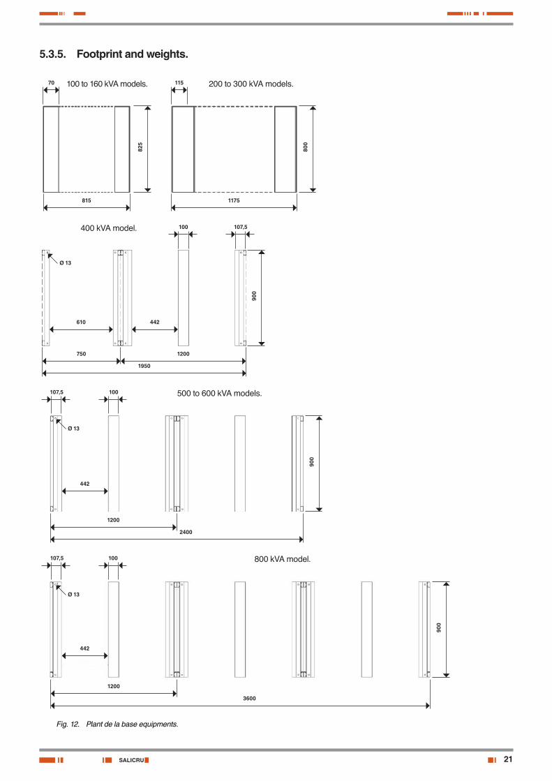
5.3.5. Footprint and weights.
70
825
815
115
800
1175
100
900
750
107,5
610 442
Ø 13
1200
1950
100
900
107,5
442
Ø 13
1200
2400
100
900
107,5
442
Ø 13
1200
3600
100 to 160 kVA models. 200 to 300 kVA models.
400 kVA model.
500 to 600 kVA models.
800 kVA model.
Fig. 12. Plant de la base equipments.
22
Model Power (kVA)
UPS
Weight (kg) Static load (kg/m2)
SLC-100-XTRA 100 625 886
SLC-125-XTRA 125 660 936
SLC-160-XTRA 160 715 1014
SLC-200-XTRA 200 970 888
SLC-250-XTRA 250 1090 988
SLC-300-XTRA 300 1170 1071
SLC-400-XTRA 400 1955 992
SLC-500-XTRA 500 2482 1027
SLC-600-XTRA 600 2535 1049
SLC-800-XTRA 800 3600 1111
Model Power (kVA)
Battery cabinet
Nr Weight (kg)
Static load (kg/m2)
SLC-100-XTRA 100 1 875 -
SLC-125-XTRA 125 1 1370 -
SLC-160-XTRA 160 1 1370 -
SLC-200-XTRA 200 1 1550 -
SLC-250-XTRA 250 1 1800 -
SLC-300-XTRA 300 2 1370 -
SLC-400-XTRA 400 2 1800 -
SLC-500-XTRA 500 2 1800 -
SLC-600-XTRA 600 2 2125 -
SLC-800-XTRA 800 3 1925 -
Note: Weight relating to batteries, are the corresponding ones to the basic standard autonomies assembled in the cabinets with 10 years lifetime -VRLA bat-teries (valve-regulated lead-acid). For other specifications, batteries or racks as-sembling, request them.
Tabla 2. Weight and static load depending on the model.
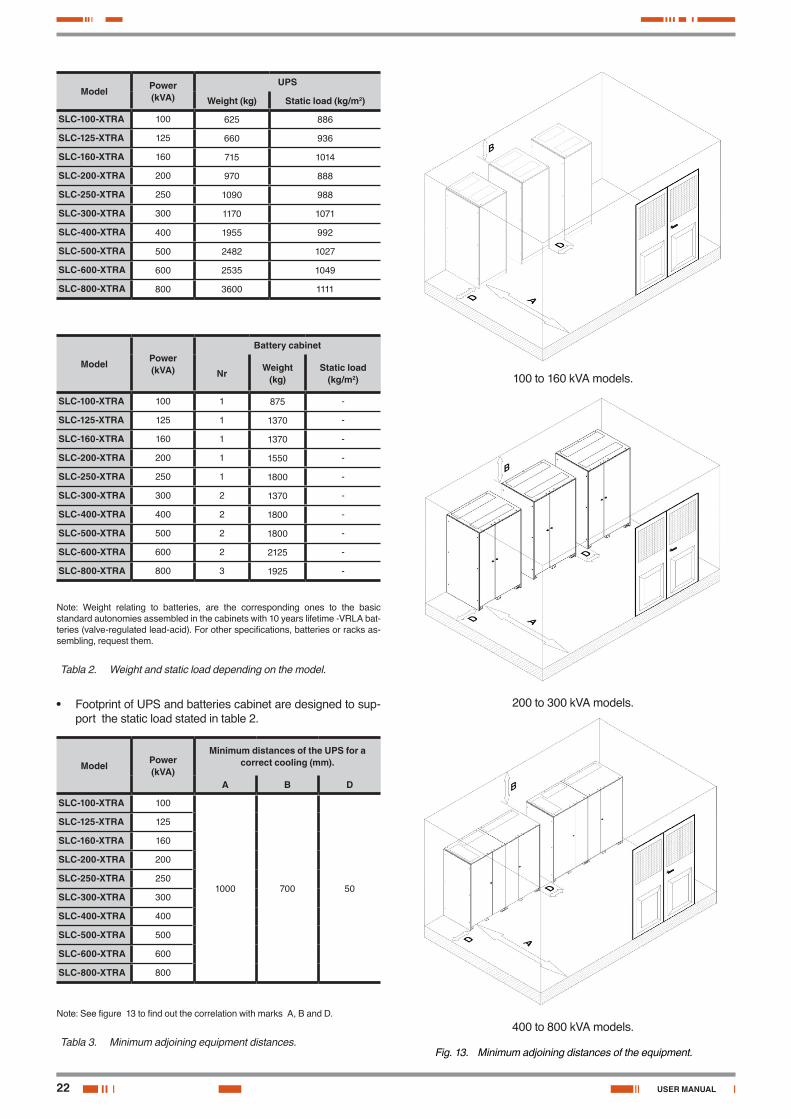
• Footprint of UPS and batteries cabinet are designed to sup-port the static load stated in table 2.
Model Power (kVA)
Minimum distances of the UPS for a correct cooling (mm).
A B D
SLC-100-XTRA 100
1000 700 50
SLC-125-XTRA 125
SLC-160-XTRA 160
SLC-200-XTRA 200
SLC-250-XTRA 250
SLC-300-XTRA 300
SLC-400-XTRA 400
SLC-500-XTRA 500
SLC-600-XTRA 600
SLC-800-XTRA 800
Note: See figure 13 to find out the correlation with marks A, B and D.
Tabla 3. Minimum adjoining equipment distances.
100 to 160 kVA models.
200 to 300 kVA models.
400 to 800 kVA models.
Fig. 13. Minimum adjoining distances of the equipment.
USER MANUAL
23SALICRU
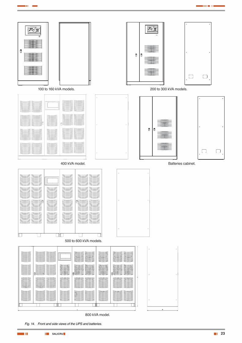
100 to 160 kVA models. 200 to 300 kVA models.
400 kVA model. Batteries cabinet.
500 to 600 kVA models.
800 kVA model.
Fig. 14. Front and side views of the UPS and batteries.
24
• Table 4 shows the minimum air flow to cool the equipment.
Deficiency of air flow cooling will block the equip-ment, but not immediately, because the over tem-
perature is acquired with over time and in proportion to the load level connected to the output.Next are stated some possible external causes to the equip-ment, which involves a bad cooling. Review and correct.
� Adjoining distances with walls or other equipments are not correct.
� Cooling grid blocking.
� To be located in room with wrong conditioning and/or di-mensions.
� Room completely sealed, avoiding the air cooling ex-hausting.
Model. Power (kVA).
Minimum air flow cooling of the equipment (m3/h).
SLC-100-XTRA 100 2100
SLC-125-XTRA 125 2300
SLC-160-XTRA 160 2500
SLC-200-XTRA 200 3500
SLC-250-XTRA 250 4100
SLC-300-XTRA 300 4500
SLC-400-XTRA 400 3500
SLC-500-XTRA 500 4000
SLC-600-XTRA 600 4500
SLC-800-XTRA 800 7000
Tabla 4. Minimum air flow cooling of the equipment.
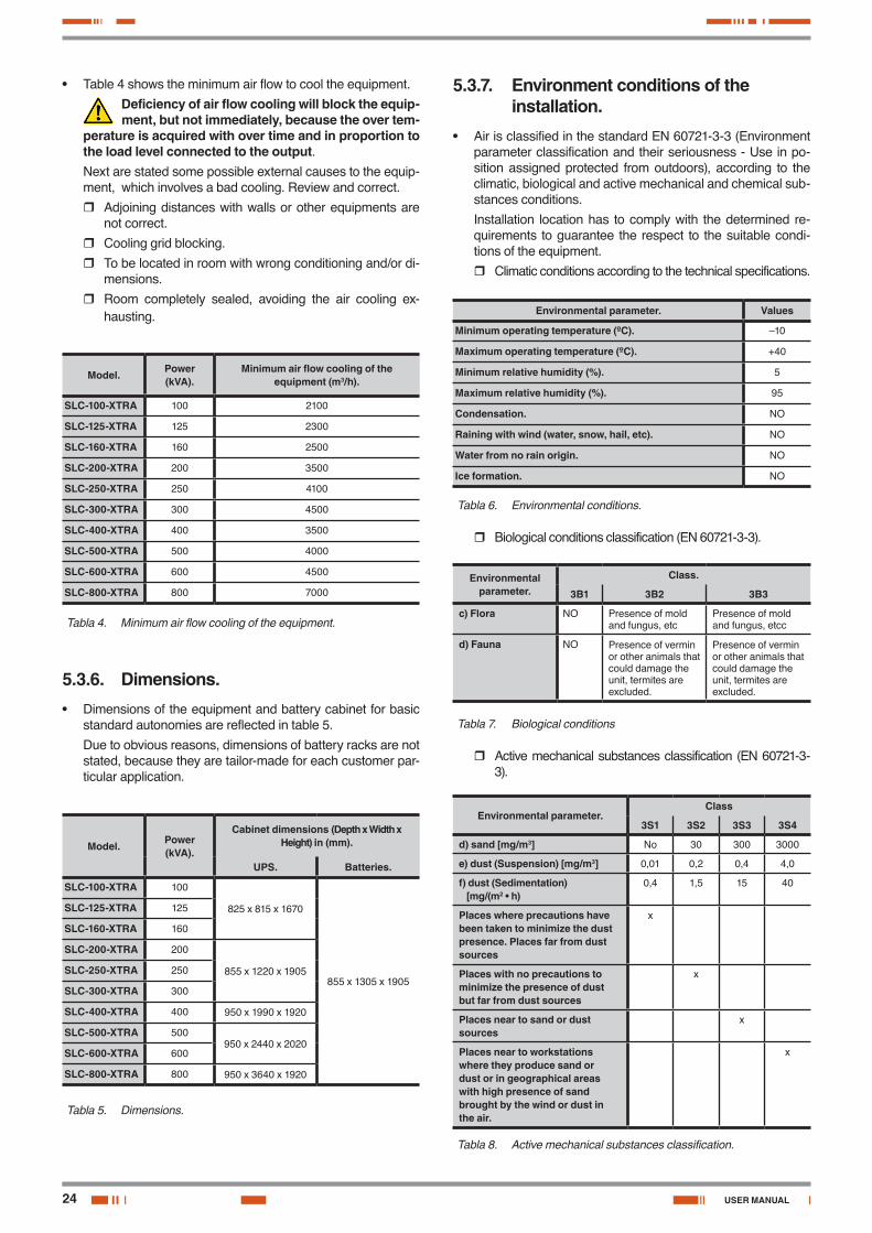
5.3.6. Dimensions.• Dimensions of the equipment and battery cabinet for basic
standard autonomies are reflected in table 5.
Due to obvious reasons, dimensions of battery racks are not stated, because they are tailor-made for each customer par-ticular application.
Model. Power (kVA).
Cabinet dimensions (Depth x Width x Height) in (mm).
UPS. Batteries.
SLC-100-XTRA 100
825 x 815 x 1670
855 x 1305 x 1905
SLC-125-XTRA 125
SLC-160-XTRA 160
SLC-200-XTRA 200
855 x 1220 x 1905SLC-250-XTRA 250
SLC-300-XTRA 300
SLC-400-XTRA 400 950 x 1990 x 1920
SLC-500-XTRA 500950 x 2440 x 2020
SLC-600-XTRA 600
SLC-800-XTRA 800 950 x 3640 x 1920
Tabla 5. Dimensions.
5.3.7. Environment conditions of the installation.
• Air is classified in the standard EN 60721-3-3 (Environment parameter classification and their seriousness - Use in po-sition assigned protected from outdoors), according to the climatic, biological and active mechanical and chemical sub-stances conditions.
Installation location has to comply with the determined re-quirements to guarantee the respect to the suitable condi-tions of the equipment.
� Climatic conditions according to the technical specifications.
Environmental parameter. Values
Minimum operating temperature (ºC). –10
Maximum operating temperature (ºC). +40
Minimum relative humidity (%). 5
Maximum relative humidity (%). 95
Condensation. NO
Raining with wind (water, snow, hail, etc). NO
Water from no rain origin. NO
Ice formation. NO
Tabla 6. Environmental conditions.
� Biological conditions classification (EN 60721-3-3).
Environmental parameter.
Class.
3B1 3B2 3B3
c) Flora NO Presence of mold and fungus, etc
Presence of mold and fungus, etcc
d) Fauna NO Presence of vermin or other animals that could damage the unit, termites are excluded.
Presence of vermin or other animals that could damage the unit, termites are excluded.
Tabla 7. Biological conditions
� Active mechanical substances classification (EN 60721-3-3).
Environmental parameter.Class
3S1 3S2 3S3 3S4
d) sand [mg/m3] No 30 300 3000
e) dust (Suspension) [mg/m3] 0,01 0,2 0,4 4,0
f) dust (Sedimentation) [mg/(m2•h)
0,4 1,5 15 40
Places where precautions have been taken to minimize the dust presence. Places far from dust sources
x
Places with no precautions to minimize the presence of dust but far from dust sources
x
Places near to sand or dust sources
x
Places near to workstations where they produce sand or dust or in geographical areas with high presence of sand brought by the wind or dust in the air.
x
Tabla 8. Active mechanical substances classification.
USER MANUAL
25SALICRU
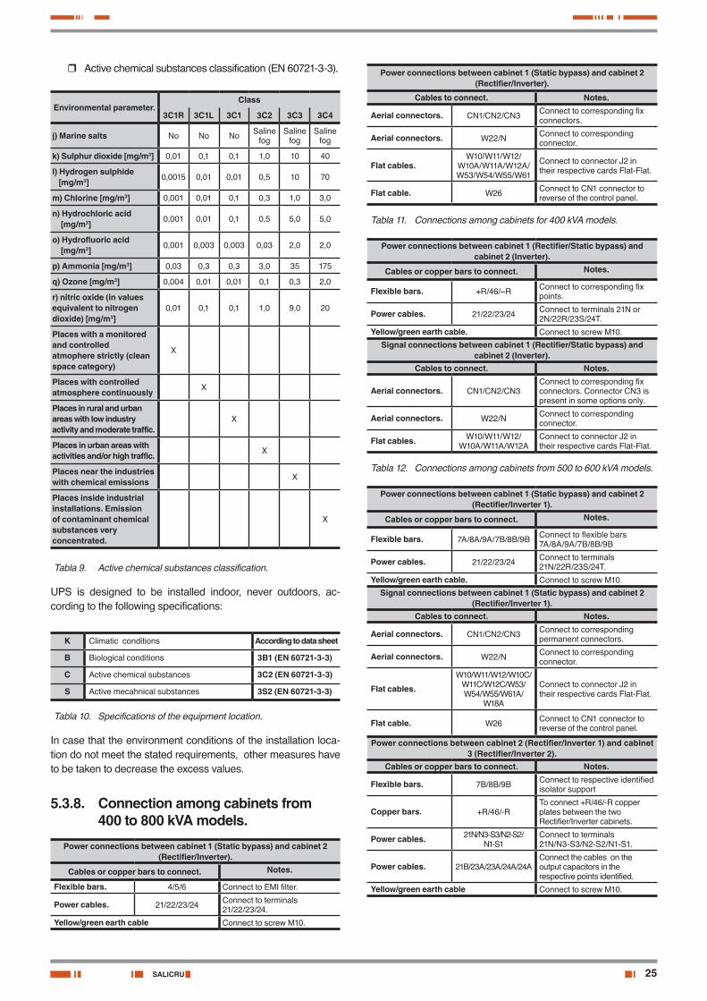
� Active chemical substances classification (EN 60721-3-3).
Environmental parameter.Class
3C1R 3C1L 3C1 3C2 3C3 3C4
j) Marine salts No No No Saline fog
Saline fog
Saline fog
k) Sulphur dioxide [mg/m3] 0,01 0,1 0,1 1,0 10 40
l) Hydrogen sulphide [mg/m3] 0,0015 0,01 0,01 0,5 10 70
m) Chlorine [mg/m3] 0,001 0,01 0,1 0,3 1,0 3,0
n) Hydrochloric acid [mg/m3] 0,001 0,01 0,1 0,5 5,0 5,0
o) Hydrofluoric acid [mg/m3] 0,001 0,003 0,003 0,03 2,0 2,0
p) Ammonia [mg/m3] 0,03 0,3 0,3 3,0 35 175
q) Ozone [mg/m3] 0,004 0,01 0,01 0,1 0,3 2,0
r) nitric oxide (in values equivalent to nitrogen dioxide) [mg/m3]
0,01 0,1 0,1 1,0 9,0 20
Places with a monitored and controlled atmophere strictly (clean space category)
X
Places with controlled atmosphere continuously X
Places in rural and urban areas with low industry activity and moderate traffic.
X
Places in urban areas with activities and/or high traffic. X
Places near the industries with chemical emissions X
Places inside industrial installations. Emission of contaminant chemical substances very concentrated.
X
Tabla 9. Active chemical substances classification.
UPS is designed to be installed indoor, never outdoors, ac-cording to the following specifications:
K Climatic conditions According to data sheet
B Biological conditions 3B1 (EN 60721-3-3)
C Active chemical substances 3C2 (EN 60721-3-3)
S Active mecahnical substances 3S2 (EN 60721-3-3)
Tabla 10. Specifications of the equipment location.
In case that the environment conditions of the installation loca-tion do not meet the stated requirements, other measures have to be taken to decrease the excess values.
5.3.8. Connection among cabinets from 400 to 800 kVA models.
Power connections between cabinet 1 (Static bypass) and cabinet 2 (Rectifier/Inverter).
Cables or copper bars to connect. Notes.
Flexible bars. 4/5/6 Connect to EMI filter.
Power cables. 21/22/23/24 Connect to terminals 21/22/23/24.
Yellow/green earth cable Connect to screw M10.
Power connections between cabinet 1 (Static bypass) and cabinet 2 (Rectifier/Inverter).
Cables to connect. Notes.
Aerial connectors. CN1/CN2/CN3 Connect to corresponding fix connectors.
Aerial connectors. W22/N Connect to corresponding connector.
Flat cables.W10/W11/W12/
W10A/W11A/W12A/W53/W54/W55/W61
Connect to connector J2 in their respective cards Flat-Flat.
Flat cable. W26 Connect to CN1 connector to reverse of the control panel.
Tabla 11. Connections among cabinets for 400 kVA models.
Power connections between cabinet 1 (Rectifier/Static bypass) and cabinet 2 (Inverter).
Cables or copper bars to connect. Notes.
Flexible bars. +R/46/–R Connect to corresponding fix points.
Power cables. 21/22/23/24 Connect to terminals 21N or 2N/22R/23S/24T.
Yellow/green earth cable. Connect to screw M10.
Signal connections between cabinet 1 (Rectifier/Static bypass) and cabinet 2 (Inverter).
Cables to connect. Notes.
Aerial connectors. CN1/CN2/CN3Connect to corresponding fix connectors. Connector CN3 is present in some options only.
Aerial connectors. W22/N Connect to corresponding connector.
Flat cables. W10/W11/W12/W10A/W11A/W12A
Connect to connector J2 in their respective cards Flat-Flat.
Tabla 12. Connections among cabinets from 500 to 600 kVA models.
Power connections between cabinet 1 (Static bypass) and cabinet 2 (Rectifier/Inverter 1).
Cables or copper bars to connect. Notes.
Flexible bars. 7A/8A/9A/7B/8B/9B Connect to flexible bars 7A/8A/9A/7B/8B/9B
Power cables. 21/22/23/24 Connect to terminals 21N/22R/23S/24T.
Yellow/green earth cable. Connect to screw M10.
Signal connections between cabinet 1 (Static bypass) and cabinet 2 (Rectifier/Inverter 1).
Cables to connect. Notes.
Aerial connectors. CN1/CN2/CN3 Connect to corresponding permanent connectors.
Aerial connectors. W22/N Connect to corresponding connector.
Flat cables.
W10/W11/W12/W10C/W11C/W12C/W53/W54/W55/W61A/
W18A
Connect to connector J2 in their respective cards Flat-Flat.
Flat cable. W26 Connect to CN1 connector to reverse of the control panel.
Power connections between cabinet 2 (Rectifier/Inverter 1) and cabinet 3 (Rectifier/Inverter 2).
Cables or copper bars to connect. Notes.
Flexible bars. 7B/8B/9B Connect to respective identified isolator support
Copper bars. +R/46/-RTo connect +R/46/-R copper plates between the two Rectifier/Inverter cabinets.
Power cables. 21N/N3-S3/N2-S2/N1-S1
Connect to terminals21N/N3-S3/N2-S2/N1-S1.
Power cables. 21B/23A/23A/24A/24AConnect the cables on the output capacitors in the respective points identified.
Yellow/green earth cable Connect to screw M10.
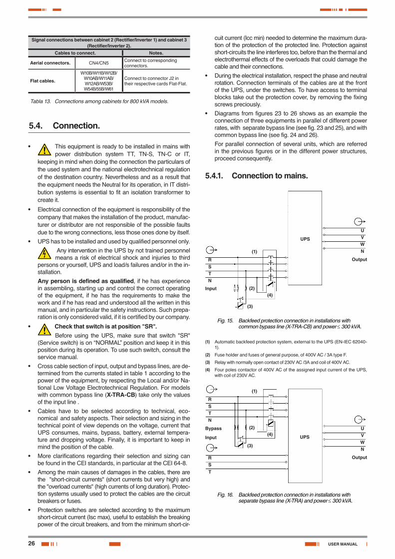
26
Signal connections between cabinet 2 (Rectifier/Inverter 1) and cabinet 3 (Rectifier/Inverter 2).
Cables to connect. Notes.
Aerial connectors. CN4/CN5 Connect to corresponding connectors.
Flat cables.
W10B/W11B/W12B/W10AB/W11AB/W12AB/W53B/W54B/55B/W61
Connect to connector J2 in their respective cards Flat-Flat.
Tabla 13. Connections among cabinets for 800 kVA models.
5.4. Connection.
• This equipment is ready to be installed in mains with power distribution system TT, TN-S, TN-C or IT,
keeping in mind when doing the connection the particulars of the used system and the national electrotechnical regulation of the destination country. Nevertheless and as a result that the equipment needs the Neutral for its operation, in IT distri-bution systems is essential to fit an isolation transformer to create it.
• Electrical connection of the equipment is responsibility of the company that makes the installation of the product, manufac-turer or distributor are not responsible of the possible faults due to the wrong connections, less those ones done by itself.
• UPS has to be installed and used by qualified personnel only.
Any intervention in the UPS by not trained personnel means a risk of electrical shock and injuries to third
persons or yourself, UPS and load/s failures and/or in the in-stallation.
Any person is defined as qualified, if he has experience in assembling, starting up and control the correct operating of the equipment, if he has the requirements to make the work and if he has read and understood all the written in this manual, and in particular the safety instructions. Such prepa-ration is only considered valid, if it is certified by our company.
• Check that switch is at position "SR".Before using the UPS, make sure that switch "SR"
(Service switch) is on “NORMAL” position and keep it in this position during its operation. To use such switch, consult the service manual.
• Cross cable section of input, output and bypass lines, are de-termined from the currents stated in table 1 according to the power of the equipment, by respecting the Local and/or Na-tional Low Voltage Electrotechnical Regulation. For models with common bypass line (X-TRA-CB) take only the values of the input line .
• Cables have to be selected according to technical, eco-nomical and safety aspects. Their selection and sizing in the technical point of view depends on the voltage, current that UPS consumes, mains, bypass, battery, external tempera-ture and dropping voltage. Finally, it is important to keep in mind the position of the cable.
• More clarifications regarding their selection and sizing can be found in the CEI standards, in particular at the CEI 64-8.
• Among the main causes of damages in the cables, there are the "short-circuit currents" (short currents but very high) and the "overload currents" (high currents of long duration). Protec-tion systems usually used to protect the cables are the circuit breakers or fuses.
• Protection switches are selected according to the maximum short-circuit current (Isc max), useful to establish the breaking power of the circuit breakers, and from the minimum short-cir-
cuit current (Icc min) needed to determine the maximum dura-tion of the protection of the protected line. Protection against short-circuits the line interferes too, before than the thermal and electrothermal effects of the overloads that could damage the cable and their connections.
• During the electrical installation, respect the phase and neutral rotation. Connection terminals of the cables are at the front of the UPS, under the switches. To have access to terminal blocks take out the protection cover, by removing the fixing screws preciously.
• Diagrams from figures 23 to 26 shows as an example the connection of three equipments in parallel of different power rates, with separate bypass line (see fig. 23 and 25), and with common bypass line (see fig. 24 and 26).
For parallel connection of several units, which are referred in the previous figures or in the different power structures, proceed consequently.
5.4.1. Connection to mains.
RS TN
UV WN(1)
(4)
(3)
(2)
UPS
Output
Input
Fig. 15. Backfeed protection connection in installations with common bypass line (X-TRA-CB) and power ≤ 300 kVA.
(1) Automatic backfeed protection system, external to the UPS (EN-IEC 62040-1).
(2) Fuse holder and fuses of general purpose, of 400V AC / 3A type F.
(3) Relay with normally open contact of 230V AC /3A and coil of 400V AC.
(4) Four poles contactor of 400V AC of the assigned input current of the UPS, with coil of 230V AC.
RS TN
UV WN
(1)
(4)
(3)
(2)
UPS
Output
Bypass
Input
RS T
Fig. 16. Backfeed protection connection in installations with separate bypass line (X-TRA) and power ≤ 300 kVA.
USER MANUAL
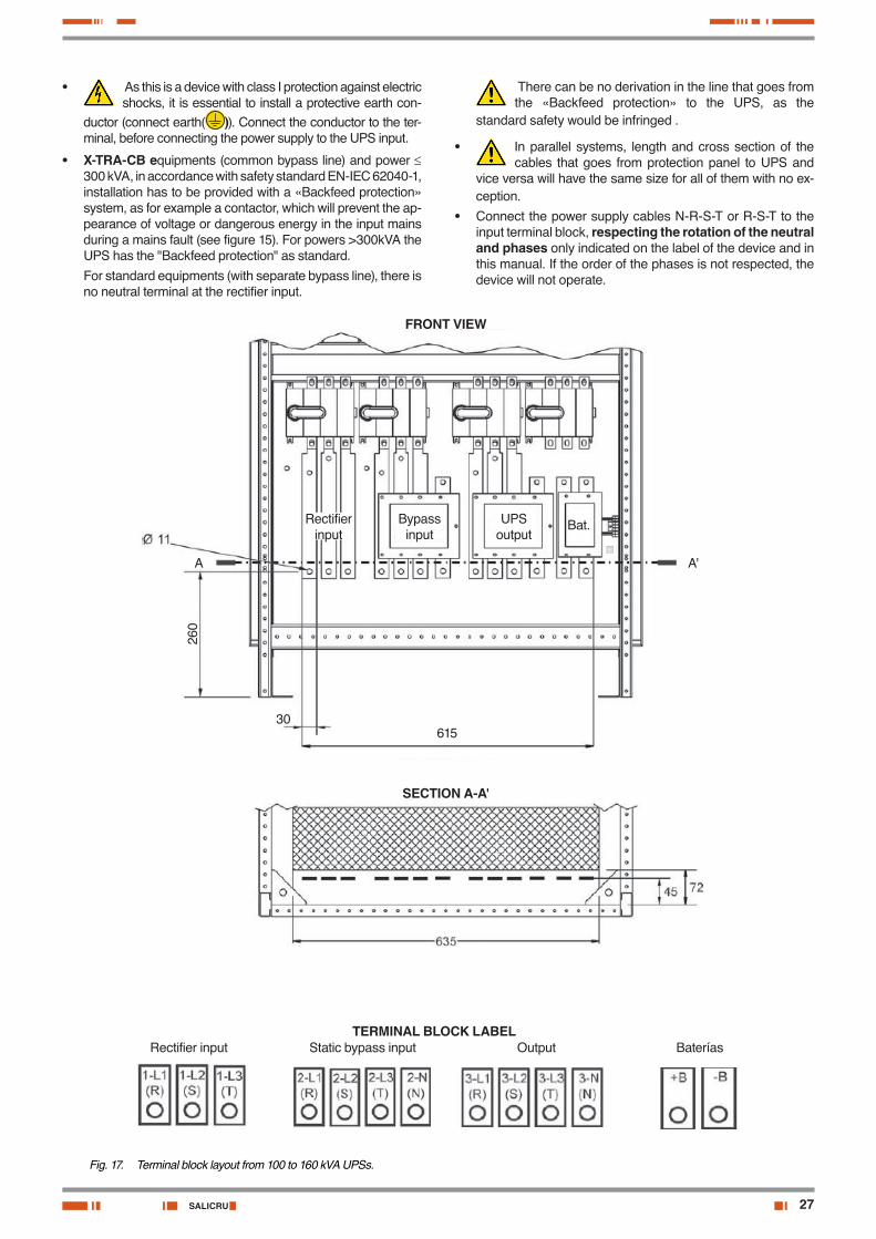
27SALICRU
• As this is a device with class I protection against electric shocks, it is essential to install a protective earth con-
ductor (connect earth( )). Connect the conductor to the ter-minal, before connecting the power supply to the UPS input.
• X-TRA-CB equipments (common bypass line) and power ≤ 300 kVA, in accordance with safety standard EN-IEC 62040-1, installation has to be provided with a «Backfeed protection» system, as for example a contactor, which will prevent the ap-pearance of voltage or dangerous energy in the input mains during a mains fault (see figure 15). For powers >300kVA the UPS has the "Backfeed protection" as standard.
For standard equipments (with separate bypass line), there is no neutral terminal at the rectifier input.
FRONT VIEW
Bypass input
UPS output
Bat.Rectifier input
SECTION A-A'
TERMINAL BLOCK LABEL Rectifier input Static bypass input Output Baterías
A A'
260
30615
Fig. 17. Terminal block layout from 100 to 160 kVA UPSs.
There can be no derivation in the line that goes from the «Backfeed protection» to the UPS, as the
standard safety would be infringed .
• In parallel systems, length and cross section of the cables that goes from protection panel to UPS and
vice versa will have the same size for all of them with no ex-ception.
• Connect the power supply cables N-R-S-T or R-S-T to the input terminal block, respecting the rotation of the neutral and phases only indicated on the label of the device and in this manual. If the order of the phases is not respected, the device will not operate.
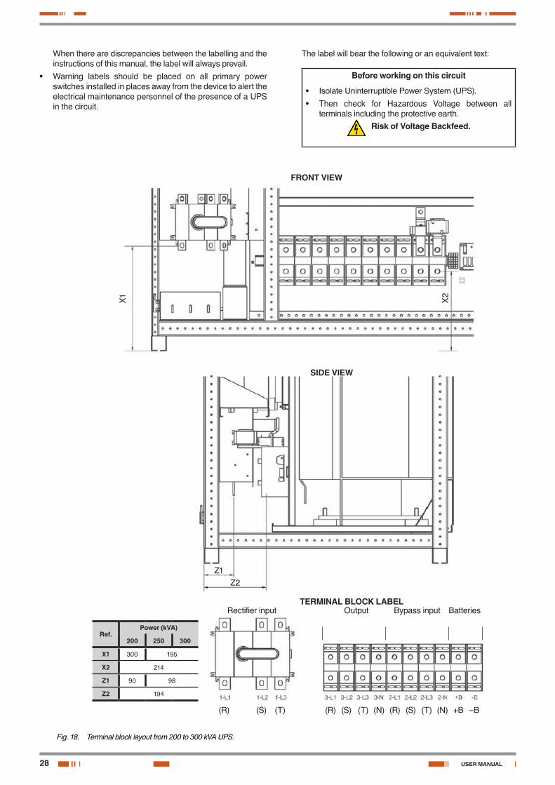
28
When there are discrepancies between the labelling and the instructions of this manual, the label will always prevail.
• Warning labels should be placed on all primary power switches installed in places away from the device to alert the electrical maintenance personnel of the presence of a UPS in the circuit.
FRONT VIEW
TERMINAL BLOCK LABEL Rectifier input Output Bypass input Batteries
X1
Z1
X2
Z2
SIDE VIEW
(R) (S) (T) (R) (S) (T) (N) (R) (S) (T) (N) +B –B
Ref.Power (kVA)
200 250 300
X1 300 195
X2 214
Z1 90 98
Z2 194
Fig. 18. Terminal block layout from 200 to 300 kVA UPS.
The label will bear the following or an equivalent text:
Before working on this circuit
• Isolate Uninterruptible Power System (UPS).
• Then check for Hazardous Voltage between all terminals including the protective earth.
Risk of Voltage Backfeed.
USER MANUAL
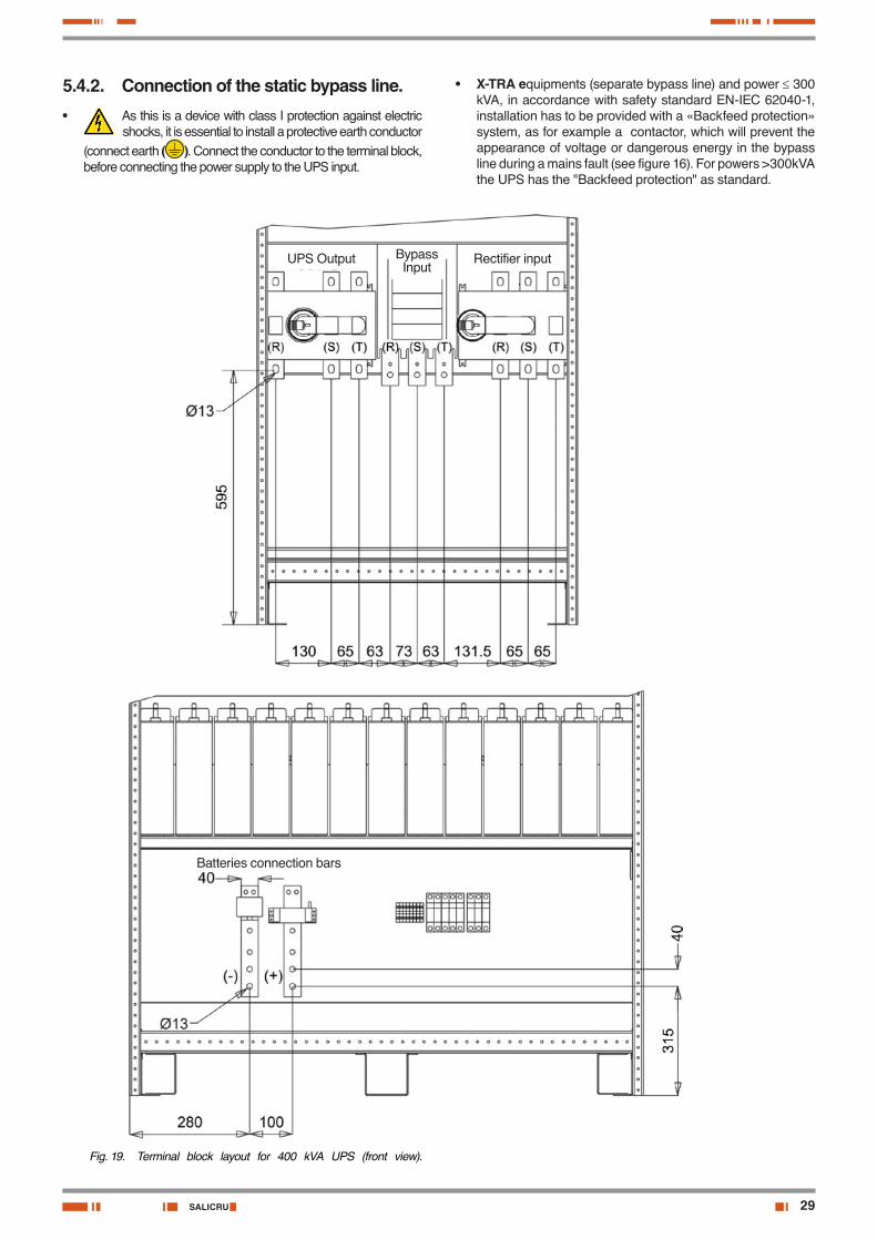
29SALICRU
5.4.2. Connection of the static bypass line.• As this is a device with class I protection against electric
shocks, it is essential to install a protective earth conductor (connect earth ( ). Connect the conductor to the terminal block, before connecting the power supply to the UPS input.
Batteries connection bars
UPS Output Bypass Input
Rectifier input
Fig. 19. Terminal block layout for 400 kVA UPS (front view).
• X-TRA equipments (separate bypass line) and power ≤ 300 kVA, in accordance with safety standard EN-IEC 62040-1, installation has to be provided with a «Backfeed protection» system, as for example a contactor, which will prevent the appearance of voltage or dangerous energy in the bypass line during a mains fault (see figure 16). For powers >300kVA the UPS has the "Backfeed protection" as standard.

30
• There can be no derivation in the line that goes from the «Backfeed protection» to the UPS, otherwise the
standard safety would be infringed.
• In parallel systems, length and cross section of the cables that goes from protection panel to UPS and
vice versa will have the same size for all of them with no ex-ception.
Static bypass neutral connection
Output neutral connection
FRONT
FRONT
Batteries connection bars
Fig. 20. Terminal block layout for 400 kVA UPS (side view).
USER MANUAL
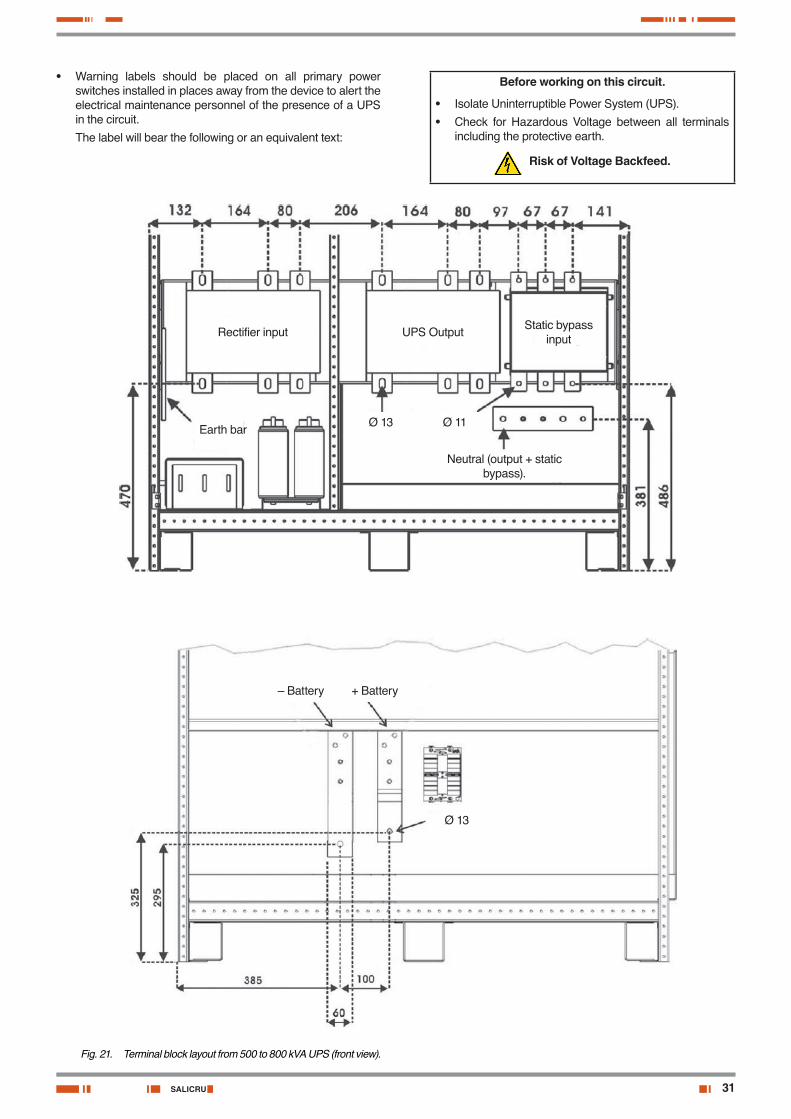
31SALICRU
• Warning labels should be placed on all primary power switches installed in places away from the device to alert the electrical maintenance personnel of the presence of a UPS in the circuit.
The label will bear the following or an equivalent text:
Rectifier input UPS Output Static bypass input
Earth barØ 13 Ø 11
Neutral (output + static bypass).
– Battery + Battery
Ø 13
Fig. 21. Terminal block layout from 500 to 800 kVA UPS (front view).
Before working on this circuit.
• Isolate Uninterruptible Power System (UPS).
• Check for Hazardous Voltage between all terminals including the protective earth.
Risk of Voltage Backfeed.

32
Connect the power supply cables N-R-S-T to the static bypass line terminals, respecting the rotation of the neutral and phases indicated on the label of the device and in this manual. If the order of the phases is not respected, the device will not operate.
When there are discrepancies between the labelling and the instructions of this manual, the label will always prevail.
Battery
FRONT
FRONT
Static bypass
Rectifier input + output
Earth bar
Output neutral + Bypass neutral
Fig. 22. Terminal block layout from 500 to 800 kVA UPS (side view).
5.4.3. Connection of the output (to loads).• As this is a device with class I protection against elec-
tric shocks, it is essential to install a protective earth conductor or bar (connect earth ( ). Connect the con-ductor or bar to the terminal, before connecting the power supply to the UPS input.
• In parallel systems, length and cross section of the cables that goes from protection panel to UPS and
vice versa will have the same size for all of them with no ex-ception.
USER MANUAL
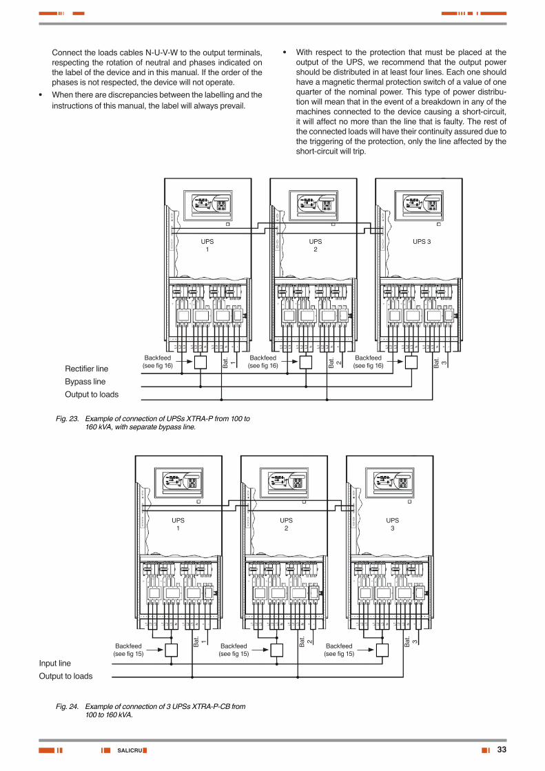
33SALICRU
Connect the loads cables N-U-V-W to the output terminals, respecting the rotation of neutral and phases indicated on the label of the device and in this manual. If the order of the phases is not respected, the device will not operate.
• When there are discrepancies between the labelling and the instructions of this manual, the label will always prevail.
Rectifier line
Bypass line
Output to loads
Backfeed (see fig 16)
Backfeed (see fig 16)
Backfeed (see fig 16)
UPS1
Bat
.1 Bat
.2 Bat
.3
UPS2
UPS 3
Fig. 23. Example of connection of UPSs XTRA-P from 100 to 160 kVA, with separate bypass line.
Input line
Output to loads
Backfeed (see fig 15)
Backfeed (see fig 15)
Backfeed (see fig 15)
UPS1
Bat
.1 Bat
.2 Bat
.3
UPS2
UPS3
Fig. 24. Example of connection of 3 UPSs XTRA-P-CB from 100 to 160 kVA.
• With respect to the protection that must be placed at the output of the UPS, we recommend that the output power should be distributed in at least four lines. Each one should have a magnetic thermal protection switch of a value of one quarter of the nominal power. This type of power distribu-tion will mean that in the event of a breakdown in any of the machines connected to the device causing a short-circuit, it will affect no more than the line that is faulty. The rest of the connected loads will have their continuity assured due to the triggering of the protection, only the line affected by the short-circuit will trip.
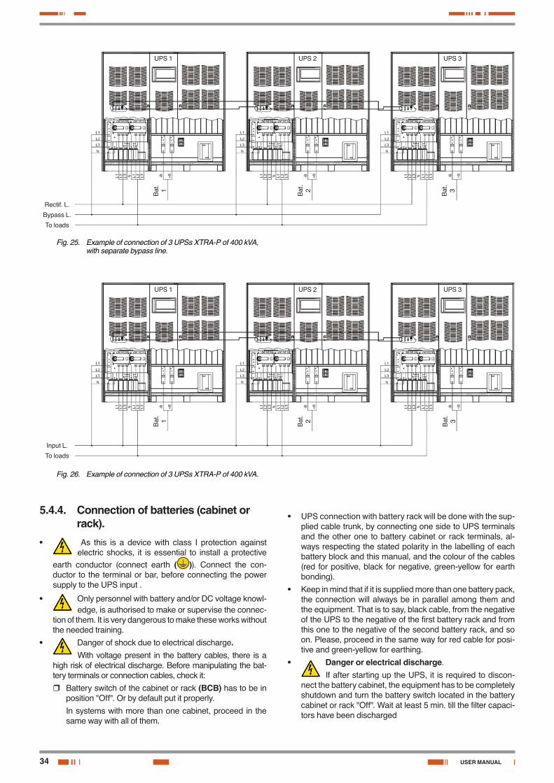
34
Rectif. L.
Bypass L.
To loads
UPS 1
Bat
.1 Bat
.2 Bat
.3
UPS 2 UPS 3
Fig. 25. Example of connection of 3 UPSs XTRA-P of 400 kVA, with separate bypass line.
Input L.
To loads
Bat
.1 Bat
.2 Bat
.3
UPS 1 UPS 2 UPS 3
Fig. 26. Example of connection of 3 UPSs XTRA-P of 400 kVA.
5.4.4. Connection of batteries (cabinet or rack).
• As this is a device with class I protection against electric shocks, it is essential to install a protective
earth conductor (connect earth ( )). Connect the con-ductor to the terminal or bar, before connecting the power supply to the UPS input .
• Only personnel with battery and/or DC voltage knowl-edge, is authorised to make or supervise the connec-
tion of them. It is very dangerous to make these works without the needed training.
• Danger of shock due to electrical discharge.With voltage present in the battery cables, there is a
high risk of electrical discharge. Before manipulating the bat-tery terminals or connection cables, check it:
� Battery switch of the cabinet or rack (BCB) has to be in position "Off". Or by default put it properly.
In systems with more than one cabinet, proceed in the same way with all of them.
• UPS connection with battery rack will be done with the sup-plied cable trunk, by connecting one side to UPS terminals and the other one to battery cabinet or rack terminals, al-ways respecting the stated polarity in the labelling of each battery block and this manual, and the colour of the cables (red for positive, black for negative, green-yellow for earth bonding).
• Keep in mind that if it is supplied more than one battery pack, the connection will always be in parallel among them and the equipment. That is to say, black cable, from the negative of the UPS to the negative of the first battery rack and from this one to the negative of the second battery rack, and so on. Please, proceed in the same way for red cable for posi-tive and green-yellow for earthing.
• Danger or electrical discharge.
If after starting up the UPS, it is required to discon-nect the battery cabinet, the equipment has to be completely shutdown and turn the battery switch located in the battery cabinet or rack "Off". Wait at least 5 min. till the filter capaci-tors have been discharged
USER MANUAL
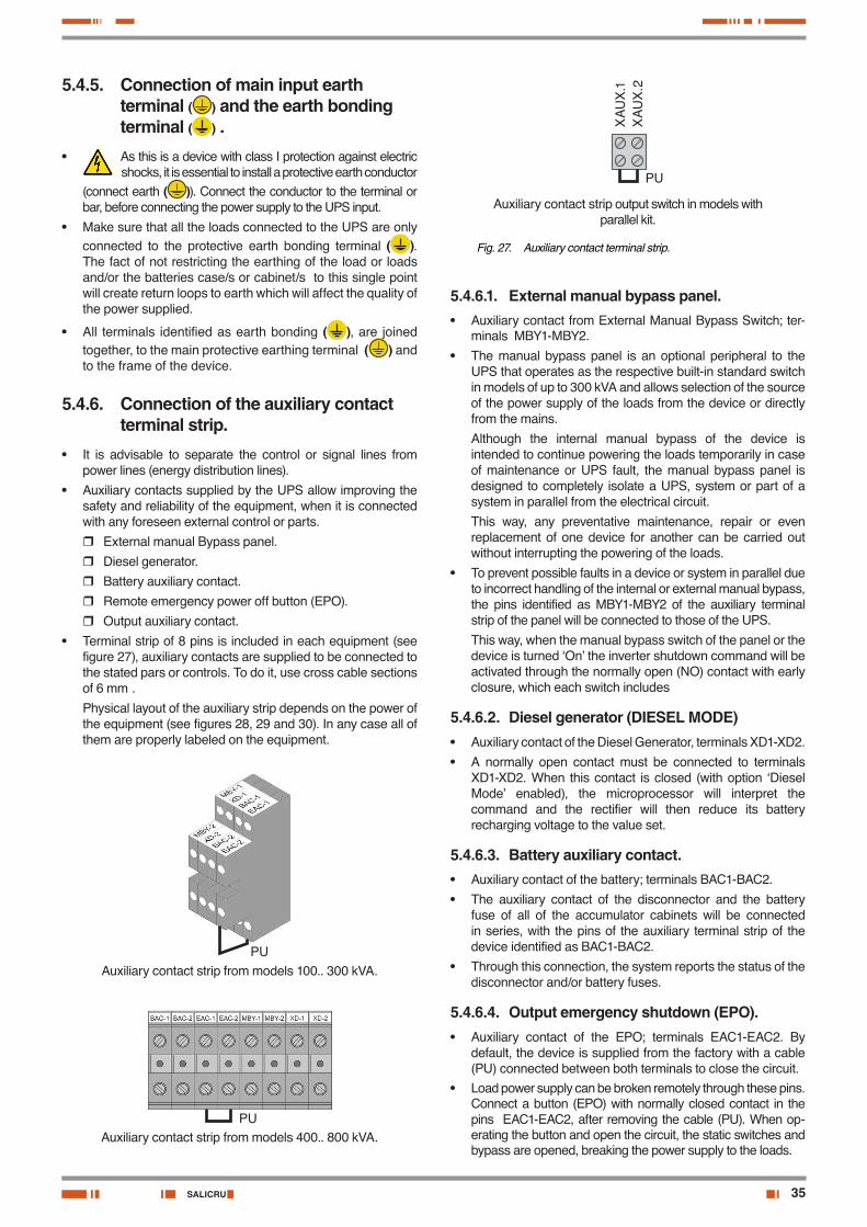
35SALICRU
5.4.5. Connection of main input earth terminal ( ) and the earth bonding terminal ( ) .
• As this is a device with class I protection against electric shocks, it is essential to install a protective earth conductor
(connect earth ( )). Connect the conductor to the terminal or bar, before connecting the power supply to the UPS input.
• Make sure that all the loads connected to the UPS are only connected to the protective earth bonding terminal ( ). The fact of not restricting the earthing of the load or loads and/or the batteries case/s or cabinet/s to this single point will create return loops to earth which will affect the quality of the power supplied.
• All terminals identified as earth bonding ( ), are joined together, to the main protective earthing terminal ( ) and to the frame of the device.
5.4.6. Connection of the auxiliary contact terminal strip.
• It is advisable to separate the control or signal lines from power lines (energy distribution lines).
• Auxiliary contacts supplied by the UPS allow improving the safety and reliability of the equipment, when it is connected with any foreseen external control or parts.
� External manual Bypass panel.
� Diesel generator.
� Battery auxiliary contact.
� Remote emergency power off button (EPO).
� Output auxiliary contact.
• Terminal strip of 8 pins is included in each equipment (see figure 27), auxiliary contacts are supplied to be connected to the stated pars or controls. To do it, use cross cable sections of 6 mm².
Physical layout of the auxiliary strip depends on the power of the equipment (see figures 28, 29 and 30). In any case all of them are properly labeled on the equipment.
Auxiliary contact strip from models 100.. 300 kVA.PU
Auxiliary contact strip from models 400.. 800 kVA.PU
XA
UX
.1X
AU
X.2
Auxiliary contact strip output switch in models with parallel kit.
PU
Fig. 27. Auxiliary contact terminal strip.
5.4.6.1. External manual bypass panel.• Auxiliary contact from External Manual Bypass Switch; ter-
minals MBY1-MBY2.
• The manual bypass panel is an optional peripheral to the UPS that operates as the respective built-in standard switch in models of up to 300 kVA and allows selection of the source of the power supply of the loads from the device or directly from the mains.
Although the internal manual bypass of the device is intended to continue powering the loads temporarily in case of maintenance or UPS fault, the manual bypass panel is designed to completely isolate a UPS, system or part of a system in parallel from the electrical circuit.
This way, any preventative maintenance, repair or even replacement of one device for another can be carried out without interrupting the powering of the loads.
• To prevent possible faults in a device or system in parallel due to incorrect handling of the internal or external manual bypass, the pins identified as MBY1-MBY2 of the auxiliary terminal strip of the panel will be connected to those of the UPS.
This way, when the manual bypass switch of the panel or the device is turned ‘On’ the inverter shutdown command will be activated through the normally open (NO) contact with early closure, which each switch includes
5.4.6.2. Diesel generator (DIESEL MODE)• Auxiliary contact of the Diesel Generator, terminals XD1-XD2.
• A normally open contact must be connected to terminals XD1-XD2. When this contact is closed (with option ‘Diesel Mode’ enabled), the microprocessor will interpret the command and the rectifier will then reduce its battery recharging voltage to the value set.
5.4.6.3. Battery auxiliary contact.• Auxiliary contact of the battery; terminals BAC1-BAC2.
• The auxiliary contact of the disconnector and the battery fuse of all of the accumulator cabinets will be connected in series, with the pins of the auxiliary terminal strip of the device identified as BAC1-BAC2.
• Through this connection, the system reports the status of the disconnector and/or battery fuses.
5.4.6.4. Output emergency shutdown (EPO).• Auxiliary contact of the EPO; terminals EAC1-EAC2. By
default, the device is supplied from the factory with a cable (PU) connected between both terminals to close the circuit.
• Load power supply can be broken remotely through these pins. Connect a button (EPO) with normally closed contact in the pins EAC1-EAC2, after removing the cable (PU). When op-erating the button and open the circuit, the static switches and bypass are opened, breaking the power supply to the loads.
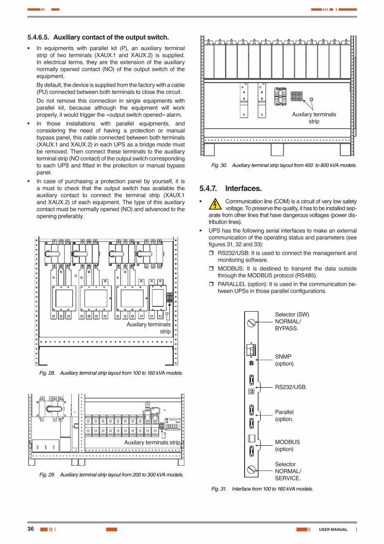
36
5.4.6.5. Auxiliary contact of the output switch.• In equipments with parallel kit (P), an auxiliary terminal
strip of two terminals (XAUX.1 and XAUX.2) is supplied. In electrical terms, they are the extension of the auxiliary normally opened contact (NO) of the output switch of the equipment.
By default, the device is supplied from the factory with a cable (PU) connected between both terminals to close the circuit.
Do not remove this connection in single equipments with parallel kit, because although the equipment will work properly, it would trigger the «output switch opened» alarm.
• In those installations with parallel equipments, and considering the need of having a protection or manual bypass panel, this cable connected between both terminals (XAUX.1 and XAUX.2) in each UPS as a bridge mode must be removed. Then connect these terminals to the auxiliary terminal strip (NO contact) of the output switch corresponding to each UPS and fitted in the protection or manual bypass panel.
• In case of purchasing a protection panel by yourself, it is a must to check that the output switch has available the auxiliary contact to connect the terminal strip (XAUX.1 and XAUX.2) of each equipment. The type of this auxiliary contact must be normally opened (NO) and advanced to the opening preferably.
Auxilary terminals strip
Fig. 28. Auxiliary terminal strip layout from 100 to 160 kVA models.
Auxilary terminals strip
Fig. 29. Auxiliary terminal strip layout from 200 to 300 kVA models.
Auxilary terminals strip
Fig. 30. Auxiliary terminal strip layout from 400 to 800 kVA models.
5.4.7. Interfaces.• Communication line (COM) is a circuit of very low safety
voltage. To preserve the quality, it has to be installed sep-arate from other lines that have dangerous voltages (power dis-tribution lines).
• UPS has the following serial interfaces to make an external communication of the operating status and parameters (see figures 31, 32 and 33):
� RS232/USB: It is used to connect the management and monitoring software.
� MODBUS: It is destined to transmit the data outside through the MODBUS protocol (RS485).
� PARALLEL (option): It is used in the communication be-tween UPSs in those parallel configurations.
Selector (SW)NORMAL/BYPASS.
SNMP (option).
RS232/USB.
Parallel (option.
MODBUS (option)
SelectorNORMAL/SERVICE.
Fig. 31. Interface from 100 to 160 kVA models.
USER MANUAL
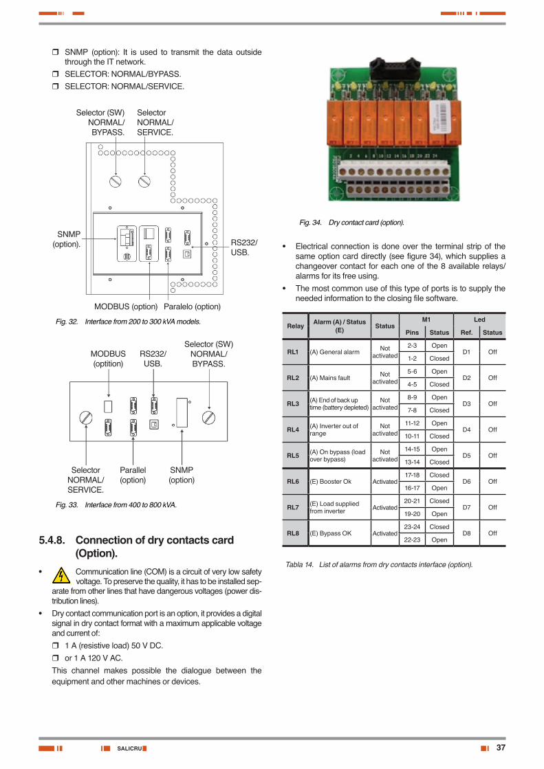
37SALICRU
� SNMP (option): It is used to transmit the data outside through the IT network.
� SELECTOR: NORMAL/BYPASS. � SELECTOR: NORMAL/SERVICE.
Paralelo (option)MODBUS (option)
SelectorNORMAL/SERVICE.
Selector (SW)NORMAL/BYPASS.
SNMP (option). RS232/
USB.
Fig. 32. Interface from 200 to 300 kVA models.
MODBUS (optition)
RS232/USB.
SelectorNORMAL/SERVICE.
Selector (SW)NORMAL/BYPASS.
Parallel (option)
SNMP (option)
Fig. 33. Interface from 400 to 800 kVA.
5.4.8. Connection of dry contacts card (Option).
• Communication line (COM) is a circuit of very low safety voltage. To preserve the quality, it has to be installed sep-
arate from other lines that have dangerous voltages (power dis-tribution lines).
• Dry contact communication port is an option, it provides a digital signal in dry contact format with a maximum applicable voltage and current of:
� 1 A (resistive load) 50 V DC.
� or 1 A 120 V AC.
This channel makes possible the dialogue between the equipment and other machines or devices.
Fig. 34. Dry contact card (option).
• Electrical connection is done over the terminal strip of the same option card directly (see figure 34), which supplies a changeover contact for each one of the 8 available relays/alarms for its free using.
• The most common use of this type of ports is to supply the needed information to the closing file software.
Relay Alarm (A) / Status (E) Status
M1 Led
Pins Status Ref. Status
RL1 (A) General alarm Not activated
2-3 OpenD1 Off
1-2 Closed
RL2 (A) Mains fault Not activated
5-6 OpenD2 Off
4-5 Closed
RL3 (A) End of back up time (battery depleted)
Not activated
8-9 OpenD3 Off
7-8 Closed
RL4 (A) Inverter out of range
Not activated
11-12 OpenD4 Off
10-11 Closed
RL5 (A) On bypass (load over bypass)
Not activated
14-15 OpenD5 Off
13-14 Closed
RL6 (E) Booster Ok Activated17-18 Closed
D6 Off16-17 Open
RL7 (E) Load supplied from inverter Activated
20-21 ClosedD7 Off
19-20 Open
RL8 (E) Bypass OK Activated23-24 Closed
D8 Off22-23 Open
Tabla 14. List of alarms from dry contacts interface (option).
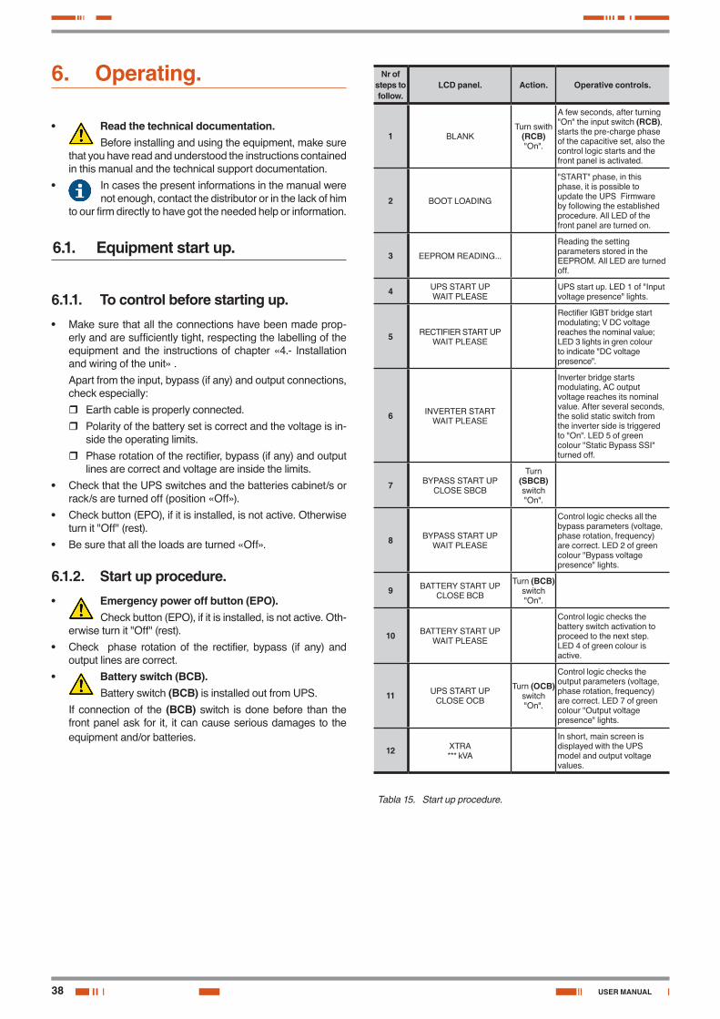
38
6. Operating.
• Read the technical documentation.Before installing and using the equipment, make sure
that you have read and understood the instructions contained in this manual and the technical support documentation.
• In cases the present informations in the manual were not enough, contact the distributor or in the lack of him
to our firm directly to have got the needed help or information.
6.1. Equipment start up.
6.1.1. To control before starting up.• Make sure that all the connections have been made prop-
erly and are sufficiently tight, respecting the labelling of the equipment and the instructions of chapter «4.- Installation and wiring of the unit» .
Apart from the input, bypass (if any) and output connections, check especially:
� Earth cable is properly connected.
� Polarity of the battery set is correct and the voltage is in-side the operating limits.
� Phase rotation of the rectifier, bypass (if any) and output lines are correct and voltage are inside the limits.
• Check that the UPS switches and the batteries cabinet/s or rack/s are turned off (position «Off»).
• Check button (EPO), if it is installed, is not active. Otherwise turn it "Off" (rest).
• Be sure that all the loads are turned «Off».
6.1.2. Start up procedure.• Emergency power off button (EPO).
Check button (EPO), if it is installed, is not active. Oth-erwise turn it "Off" (rest).
• Check phase rotation of the rectifier, bypass (if any) and output lines are correct.
• Battery switch (BCB).Battery switch (BCB) is installed out from UPS.
If connection of the (BCB) switch is done before than the front panel ask for it, it can cause serious damages to the equipment and/or batteries.
Nr of steps to follow.
LCD panel. Action. Operative controls.
1 BLANKTurn swith
(RCB) "On".
A few seconds, after turning "On" the input switch (RCB), starts the pre-charge phase of the capacitive set, also the control logic starts and the front panel is activated.
2 BOOT LOADING
"START" phase, in this phase, it is possible to update the UPS Firmware by following the established procedure. All LED of the front panel are turned on.
3 EEPROM READING...
Reading the setting parameters stored in the EEPROM. All LED are turned off.
4 UPS START UPWAIT PLEASE
UPS start up. LED 1 of "Input voltage presence" lights.
5 RECTIFIER START UPWAIT PLEASE
Rectifier IGBT bridge start modulating; V DC voltage reaches the nominal value; LED 3 lights in gren colour to indicate "DC voltage presence".
6 INVERTER STARTWAIT PLEASE
Inverter bridge starts modulating, AC output voltage reaches its nominal value. After several seconds, the solid static switch from the inverter side is triggered to "On". LED 5 of green colour "Static Bypass SSI" turned off.
7 BYPASS START UPCLOSE SBCB
Turn (SBCB) switch "On".
8 BYPASS START UPWAIT PLEASE
Control logic checks all the bypass parameters (voltage, phase rotation, frequency) are correct. LED 2 of green colour "Bypass voltage presence" lights.
9 BATTERY START UPCLOSE BCB
Turn (BCB) switch "On".
10 BATTERY START UPWAIT PLEASE
Control logic checks the battery switch activation to proceed to the next step.LED 4 of green colour is active.
11 UPS START UPCLOSE OCB
Turn (OCB) switch "On".
Control logic checks the output parameters (voltage, phase rotation, frequency) are correct. LED 7 of green colour "Output voltage presence" lights.
12 XTRA*** kVA
In short, main screen is displayed with the UPS model and output voltage values.
Tabla 15. Start up procedure.
USER MANUAL

39SALICRU
6.1.3. Basic troubleshooting.This section summarizes some basic indications in case of problems during the start up. If problem is not solved, contact with our Service and Technical Support (S.T.S.).
• After turning "On" (RCB) switch, the screen from control panel is still off.
� Check the phase rotation of the mains or power supply. Rectifier input mains and bypass if any have to be checked.
� Check input voltage and frequency are inside the limits.
� Check that rectifier protection fuses F1-F2-F3, are fitted in the UPS.
• After the step Nr 1 from table 15, the UPS blocks the start up process and it displays one or more alarm messages.
� Check the displayed alarms and find out the causes.
� Turn the (RCB) switch off and start up the UPS again.
• After the step Nr 2 from table 15, the alarm A15 is displayed -Bypass not available.-.
� Check that (SBCB) switch has been turned "On".
� Check the protection fuses from static Bypass; are fitted in the UPS.
� Check the phase rotation of bypass line.
� Check input voltage and frequency are inside the limits.
• After the step Nr 3 from table 15, the alarm A7 is displayed -BCB open-.
� Check the (BCB) battery switch is turned "On"; switch or fuseholder is fitted in the battery cabinet/s or rack/s.
� Check the battery fuses.
� Check the interlink between the auxiliary contact of the battery switch (BCB) that you can find in the battery cabinet/s or rack/s and BAC1-BAC2 terminals of UPS.
6.2. Equipment shutdown.
Nr of steps to follow.
Action. LCD screen. Operating controls.
1 Turn (OCB) switch "Off".
A30 GENERAL ALARM
Load power supply broken. LED 7 turn off.
2 Turn (BCB) switch "Off".
A30 GENERAL ALARM
Battery-rectifier disconnected. Red LED 4 blinks.
3 Turn switch (SBCB) "Off".
A30 GENERAL ALARM
Bypass power sypply disconnection. LED 2 turned off.
4 Turn switch (RCB) "Off".
A30 GENERAL ALARM
Rectifier and inverter are shutdown, they are out of service.
5 BLANK End of shutdown procedure.
Tabla 16. Shutdown procedure.
6.3. Manual bypass, single equipment (maintenance bypass).
6.3.1. Operating principle.The integrated manual bypass of the UPS is a very useful ele-ment, but undue use can have irreversible consequences for both the UPS and the loads connected to its output. Therefore, it is important to handle it, as it is described in the following para-graphs.
6.3.2. Transference from normal mode to maintenance bypass.
Transference operation of the load/s power supply over the manual bypass is done with no break in the power supply of themselves.
• Manual bypass.To execute the transfer procedure in the right way,
check that there are not any active alarms in the system.
On manual bypass position, load is supplied from input mains directly, therefore it is not possible to guarantee a continuous power supply to the loads, either its quality.
Nr of steps to follow.
Action. LCD screen Operating controls
1
Move Bypass selector (SW) to
"Bypass" position.
A30 GENERAL ALARM
Transfer the load over the bypass line. LED 5 turned off, orange LED 6 lights.
2Turn
(MBCB) switch "On".
A30 GENERAL ALARM
Inverter shutdown. Load is supplied from input mains through the manual bypass switch (MBCB). Static bypass switch (SBCB), is still turned "On". Orange LED 8 lights.
3 Turn (BCB) switch "Off".
A30 GENERAL ALARM
DC energy protection (batteries), is disconnected. Red LED 4 blinks.
4 Turn (RCB) switch "Off".
A30 GENERAL ALARM
AC input energy power supply protection is disconnected. Rectifier is shutdown. LED 1 turned off.
5 Turn (OCB) switch "Off".
A30 GENERAL ALARM
Load is supplied from manual bypass switch (selector (SW) to Bypass position). LED 8 is shutdown.
6 Turn (SBCB) switch "Off".
A30 GENERAL ALARM
Bypass line is disconnected. LCD screen from control panel are completely shutdown.
7 UPS shutdown. BLANK
Load is supplied directly from AC mains through the manual bypass switch. UPS is isolated.
Tabla 17. Procedure to make the transference from normal mode to maintenance bypass (manual bypass).

40
6.3.3. Transference from maintenance bypass to normal mode.
Before starting up the UPS, check that selector (SW) is on "By-pass" position and manual bypass switch (MBCB) is turned "On".
Nr of steps to follow.
LCD screen Action Operating controls
1LCD screen of the control panel and LED indicators
off.
Turn (RCB) switch "On".
2 BOOT LOADING
"START" phase, in this phase it is possible to update the UPS firmware by following the established procedure. All LED from control panel light.
3 EEPROM READING
Reading the setting parameters stored in the EEPROM. All LED will be shutdown.
4 UPS START UPWAIT PLEASE
Rectifier is supplied and DC voltage reaches the nominal value. All LED's from control panel light.Microprocessor checks that all start conditions are correct for starting up. LED 1 lights in green and LED 8 in orange.
5 RECTIFIER START UPWAIT PLEASE
IGBT rectifier bridge starts modulating; V DC voltage reaches the nominal value; LED 3 lights on green colour to indicate "DC voltage presence".
6 START UP FROM MBCBCLOSE SBCB
Turn (SBCB) switch "On".
7 START UP FROM MBCBWAIT PLEASE
Microprocessor checks that all bypass parameters (voltage, phase rotation, frequency) are inside the limits. LED 2 lights on green colour. Solid static switch is triggered to "On", LED 6 lights on orange colour.
8 START UP FROM MBCBCLOSE BCB
Turn (BCB) switch "On".
9 START UP FROM MBCBWAIT PLEASE
Control logic checks the battery switch activation to proceed to the next step.LED 4 of green colour is active.
10 START UP FROM MBCBCLOSE OCB
Turn (OCB) switch "On".
Load is supplied by the static solid switch. (MBCB) switch is still turned "On". LED 7 in green.
11 START UP FROM MBCBOPEN MBCB
Turn (MBCB) switch "Off".
Solid static bypass switch feeds the load and the inverter can start. LED 8 is shutdown.
12 INVERTER STARTWAIT PLEASE
Modulation is started in the inverter bridge and the AC voltage reaches the nominal value. Microprocessor controls the synchronisation of the static bypass line.
13 START UP FROM MBCBMOVE BYP-SWITCH
Move Bypass selector (SW) to
"Normal" position.
Transference of the load over the inverter. LED 5 in green.
14 XTRA*** kVA
In short, main screen is displayed with the UPS model and output voltage values.
Tabla 18. Procedure of transference from maintenance bypass (manual bypass) to normal mode.
6.4. Procedure to start up a parallel system X-TRA-P.
6.4.1. Parallel system start up and checking.
• Parallel system checking will be done on manual bypass mode.
• The following actions, have to be done at all the equipments that make the system, unless otherwise stated:
� Turn MBCB switch "On".
� Put "bypass selector", to bypass position.
� Turn RCB switch "On".
� Follow the start up instructions that are displayed in the LCD panel of each equipment with the message: "OPEN ALL MBCB". Do not perform the action yet on manual bypass switches MBCB.
� Proceed as indicated in the previous point for the remaining UPSs.
� Make sure that static bypass switch SBCB is ‘On’ on all of the UPSs.
� Set manual bypass switch MBCB to ‘Off’ on all of the UPSs.
� Follow the instructions on screen. Set the ‘bypass selector’ to NORMAL on all of the UPSs, starting with UPS No. 1.
• WARNING. � If the message in the screen displays "OPEN MBCB" in-
stead of "OPEN ALL MBCB", it means that the equipment is set to single mode and not parallel.
It is essential to set each one of the UPSs properly before continuing.
� It is not possible that two or more equipments are set or converted as MASTER at the same time.
• If UPS configuration has been checked and it is correct, pro-ceed to start up when the message in the LCD panel is dis-played "OPEN ALL MBCB.
• After it, put the bypass selector to "Normal" position. Parallel system will supply output voltage in N-1 configurations, if by-pass selector is on "Normal" position only.
• Put the bypass switch to "Normal" position in the last equip-ment.
• UPS supplies the output in parallel if the message displayed in the LCD is "START UP ENDED".
6.4.2. Start up X-TRA-P.
6.4.2.1. Direct start up, in case of 2 UPS.
• When the system is made of two UPS, it is possible to start up the system directly. In the start up UPS procedure, turn RCB switch "On" and follow the steps of the LCD screen as-sistance. Next make the same operations in the other UPS.
6.4.2.2. Start up from manual bypass, 2 UPSs case.
• When the system is made by two UPSs, it is also possible to start up the parallel system with the manual bypass.
If the UPSs are already on manual bypass, check the two first steps.
USER MANUAL
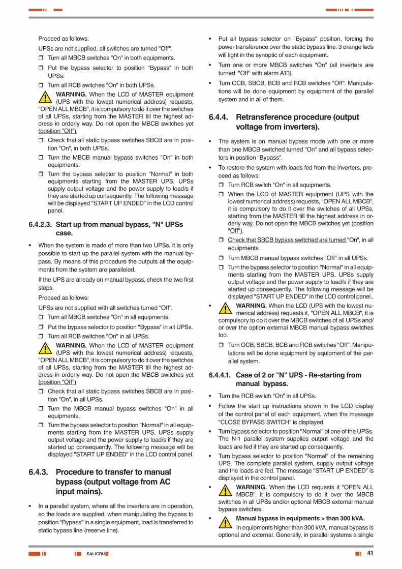
41SALICRU
Proceed as follows:
UPSs are not supplied, all switches are turned "Off".
� Turn all MBCB switches "On" in both equipments.
� Put the bypass selector to position "Bypass" in both UPSs.
� Turn all RCB switches "On" in both UPSs.
WARNING. When the LCD of MASTER equipment (UPS with the lowest numerical address) requests,
"OPEN ALL MBCB", it is compulsory to do it over the switches of all UPSs, starting from the MASTER till the highest ad-dress in orderly way. Do not open the MBCB switches yet (position "Off").
� Check that all static bypass switches SBCB are in posi-tion "On", in both UPSs.
� Turn the MBCB manual bypass switches "On" in both equipments.
� Turn the bypass selector to position "Normal" in both equipments starting from the MASTER UPS. UPSs supply output voltage and the power supply to load/s if they are started up consequently. The following message will be displayed "START UP ENDED" in the LCD control panel.
6.4.2.3. Start up from manual bypass, "N" UPSs case.
• When the system is made of more than two UPSs, it is only possible to start up the parallel system with the manual by-pass. By means of this procedure the outputs all the equip-ments from the system are paralleled.
If the UPS are already on manual bypass, check the two first steps.
Proceed as follows:
UPSs are not supplied with all switches turned "Off".
� Turn all MBCB switches "On" in all equipments.
� Put the bypass selector to position "Bypass" in all UPSs.
� Turn all RCB switches "On" in all UPSs.
WARNING. When the LCD of MASTER equipment (UPS with the lowest numerical address) requests,
"OPEN ALL MBCB", it is compulsory to do it over the switches of all UPSs, starting from the MASTER till the highest ad-dress in orderly way. Do not open the MBCB switches yet (position "Off")
� Check that all static bypass switches SBCB are in posi-tion "On", in all UPSs.
� Turn the MBCB manual bypass switches "On" in all equipments.
� Turn the bypass selector to position "Normal" in all equip-ments starting from the MASTER UPS. UPSs supply output voltage and the power supply to load/s if they are started up consequently. The following message will be displayed "START UP ENDED" in the LCD control panel.
6.4.3. Procedure to transfer to manual bypass (output voltage from AC input mains).
• In a parallel system, where all the inverters are in operation, so the loads are supplied, when manipulating the bypass to position "Bypass" in a single equipment, load is transferred to static bypass line (reserve line).
• Put all bypass selector on "Bypass" position, forcing the power transference over the static bypass line. 3 orange leds will light in the synoptic of each equipment.
• Turn one or more MBCB switches "On" (all inverters are turned "Off" with alarm A13).
• Turn OCB, SBCB, BCB and RCB switches "Off". Manipula-tions will be done equipment by equipment of the parallel system and in all of them.
6.4.4. Retransference procedure (output voltage from inverters).
• The system is on manual bypass mode with one or more than one MBCB switched turned "On" and all bypass selec-tors in position "Bypass".
• To restore the system with loads fed from the inverters, pro-ceed as follows:
� Turn RCB switch "On" in all equipments.
� When the LCD of MASTER equipment (UPS with the lowest numerical address) requests, "OPEN ALL MBCB", it is compulsory to do it over the switches of all UPSs, starting from the MASTER till the highest address in or-derly way. Do not open the MBCB switches yet (position "Off").
� Check that SBCB bypass switched are turned "On", in all equipments.
� Turn MBCB manual bypass switches "Off" in all UPSs.
� Turn the bypass selector to position "Normal" in all equip-ments starting from the MASTER UPS. UPSs supply output voltage and the power supply to load/s if they are started up consequently. The following message will be displayed "START UP ENDED" in the LCD control panel..
• WARNING. When the LCD (UPS with the lowest nu-merical address) requests it, "OPEN ALL MBCB", it is
compulsory to do it over the MBCB switches of all UPSs and/or over the option external MBCB manual bypass switches too.
� Turn OCB, SBCB, BCB and RCB switches "Off". Manipu-lations will be done equipment by equipment of the par-allel system.
6.4.4.1. Case of 2 or "N" UPS - Re-starting from manual bypass.
• Turn the RCB switch "On" in all UPSs.
• Follow the start up instructions shown in the LCD display of the control panel of each equipment, when the message "CLOSE BYPASS SWITCH" is displayed.
• Turn bypass selector to position "Normal" of one of the UPSs. The N-1 parallel system supplies output voltage and the loads are fed if they are started up consequently.
• Turn bypass selector to position "Normal" of the remaining UPS. The complete parallel system, supply output voltage and the loads are fed. The message "START UP ENDED" is displayed in the control panel.
• WARNING. When the LCD requests it "OPEN ALL MBCB", it is compulsory to do it over the MBCB
switches in all UPSs and/or optional MBCB external manual bypass switches.
• Manual bypass in equipments > than 300 kVA.In equipments higher than 300 kVA, manual bypass is
optional and external. Generally, in parallel systems a single

42
manual bypass is supplied, which will be common for all of them and fitted in a metallic case.
• Manual bypass.In systems with more than 2 UPSs, the inverters are
controlled by the N-1 logic, N inverter.
Therefore, in a system of 3 UPSs, the normal operating mode will be restored till the bypass selector of the second equip-ment is not turned to position "Normal" and the start up pro-cedure of itself is completed.
USER MANUAL
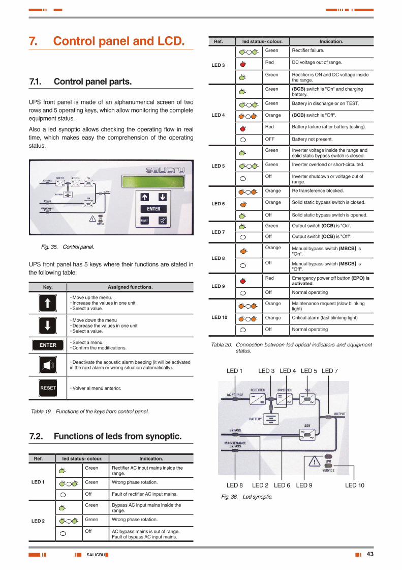
43SALICRU
7. Control panel and LCD.
7.1. Control panel parts.
UPS front panel is made of an alphanumerical screen of two rows and 5 operating keys, which allow monitoring the complete equipment status.
Also a led synoptic allows checking the operating flow in real time, which makes easy the comprehension of the operating status.
Fig. 35. Control panel.
UPS front panel has 5 keys where their functions are stated in the following table:
Key. Assigned functions.
• Move up the menu.• Increase the values in one unit.• Select a value.
• Move down the menu• Decrease the values in one unit• Select a value.
• Select a menu.• Confirm the modifications.
• Deactivate the acoustic alarm beeping (it will be activated in the next alarm or wrong situation automatically).
• Volver al menú anterior.
Tabla 19. Functions of the keys from control panel.
7.2. Functions of leds from synoptic.
Ref. led status- colour. Indication.
LED 1
Green Rectifier AC input mains inside the range.
Green Wrong phase rotation.
Off Fault of rectifier AC input mains.
LED 2
Green Bypass AC input mains inside the range.
Green Wrong phase rotation.
Off AC bypass mains is out of range.Fault of bypass AC input mains.
Ref. led status- colour. Indication.
LED 3
Green Rectifier failure.
Red DC voltage out of range.
Green Rectifier is ON and DC voltage inside the range.
LED 4
Green (BCB) switch is "On" and charging battery.
Green Battery in discharge or on TEST.
Orange (BCB) switch is "Off".
Red Battery failure (after battery testing).
OFF Battery not present.
LED 5
Green Inverter voltage inside the range and solid static bypass switch is closed.
Green Inverter overload or short-circuited.
Off Inverter shutdown or voltage out of range.
LED 6
Orange Re transference blocked.
Orange Solid static bypass switch is closed.
Off Solid static bypass switch is opened.
LED 7Green Output switch (OCB) is "On".
Off Output switch (OCB) is "Off".
LED 8
Orange Manual bypass switch (MBCB) is "On".
Off Manual bypass switch (MBCB) is "Off".
LED 9
Red Emergency power off button (EPO) is activated.
Off Normal operating
LED 10
Orange Maintenance request (slow blinking light)
Orange Critical alarm (fast blinking light)
Off Normal operating
Tabla 20. Connection between led optical indicators and equipment status.
LED 10LED 9LED 8 LED 6LED 2
LED 7LED 5LED 1 LED 4LED 3
Fig. 36. Led synoptic.
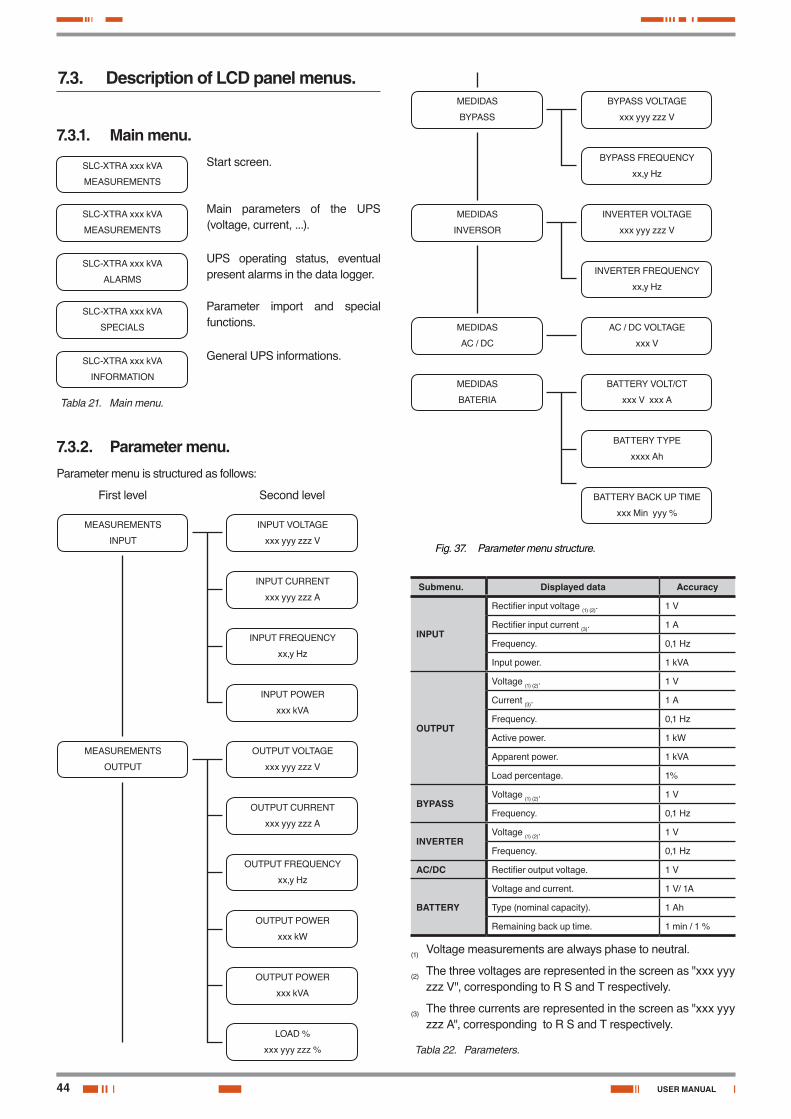
44
7.3. Description of LCD panel menus.
7.3.1. Main menu.
SLC-XTRA xxx kVA
MEASUREMENTS
Start screen.
SLC-XTRA xxx kVA
MEASUREMENTS
Main parameters of the UPS (voltage, current, ...).
SLC-XTRA xxx kVA
ALARMS
UPS operating status, eventual present alarms in the data logger.
SLC-XTRA xxx kVA
SPECIALS
Parameter import and special functions.
SLC-XTRA xxx kVA
INFORMATION
General UPS informations.
Tabla 21. Main menu.
7.3.2. Parameter menu.Parameter menu is structured as follows:
First level Second level
MEASUREMENTS
INPUT
MEASUREMENTS
OUTPUT
INPUT VOLTAGE
xxx yyy zzz V
OUTPUT VOLTAGE
xxx yyy zzz V
OUTPUT CURRENT
xxx yyy zzz A
OUTPUT FREQUENCY
xx,y Hz
OUTPUT POWER
xxx kW
OUTPUT POWER
xxx kVA
LOAD %
xxx yyy zzz %
INPUT CURRENT
xxx yyy zzz A
INPUT FREQUENCY
xx,y Hz
INPUT POWER
xxx kVA
MEDIDAS
BYPASS
MEDIDAS
INVERSOR
MEDIDAS
AC / DC
MEDIDAS
BATERIA
BYPASS VOLTAGE
xxx yyy zzz V
INVERTER VOLTAGE
xxx yyy zzz V
INVERTER FREQUENCY
xx,y Hz
AC / DC VOLTAGE
xxx V
BATTERY VOLT/CT
xxx V xxx A
BATTERY TYPE
xxxx Ah
BATTERY BACK UP TIME
xxx Min yyy %
BYPASS FREQUENCY
xx,y Hz
Fig. 37. Parameter menu structure.
Submenu. Displayed data Accuracy
INPUT
Rectifier input voltage (1) (2). 1 V
Rectifier input current (3). 1 A
Frequency. 0,1 Hz
Input power. 1 kVA
OUTPUT
Voltage (1) (2). 1 V
Current (3). 1 A
Frequency. 0,1 Hz
Active power. 1 kW
Apparent power. 1 kVA
Load percentage. 1%
BYPASSVoltage (1) (2). 1 V
Frequency. 0,1 Hz
INVERTERVoltage (1) (2). 1 V
Frequency. 0,1 Hz
AC/DC Rectifier output voltage. 1 V
BATTERY
Voltage and current. 1 V/ 1A
Type (nominal capacity). 1 Ah
Remaining back up time. 1 min / 1 %
(1) Voltage measurements are always phase to neutral.
(2) The three voltages are represented in the screen as "xxx yyy zzz V", corresponding to R S and T respectively.
(3) The three currents are represented in the screen as "xxx yyy zzz A", corresponding to R S and T respectively.
Tabla 22. Parameters.
USER MANUAL
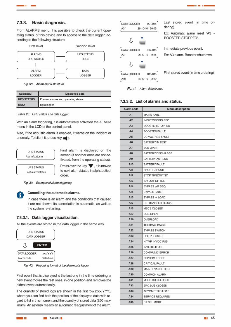
45SALICRU
7.3.3. Basic diagnosis.From ALARMS menu, it is possible to check the current oper-ating status of this device and to access to the data logger, ac-cording to the following structure:
First level Second level
ALARMS
UPS STATUS
ALARM
LOGGER
UPS STATUS
LOGS
DATA
LOGGER
Fig. 38. Alarm menu structure.
Submenu Displayed data
UPS STATUS Present alarms and operating status.
DATA Data logger.
Tabla 23. UPS status and data logger.
With an alarm triggering, it is automatically activated the ALARM menu in the LCD of the control panel.
Also, if the acoustic alarm is enabled, it warns on the incident or anomaly. To silent it, press key .
UPS STATUS
Alarm/status nr 1
First alarm is displayed on the screen (if another ones are not ac-tivated, from the operating status).
UPS STATUS
Last alarm/status
Press over the key , it is moved to next alarm/status in alphabetical order.
Fig. 39. Example of alarm triggering.
Cancelling the automatic alarms.
In case there is an alarm and the conditions that caused it are not shown, its cancellation is automatic, as well as the system re-starting.
7.3.3.1. Data logger visualization.All the events are stored in the data logger in the same way.
UPS STATUS
DATA LOGGER
DATA LOGGER xxx/YYY
Alarm code Date/time
Fig. 40. Reporting format of the alarm data logger.
First event that is displayed is the last one in the time ordering; a new event moves the rest ones, in one position and removes the oldest event automatically.
The quantity of stored logs are shown in the first row (xxx/YYY), where you can find both the position of the displayed data with re-gard to list in this moment and the quantity of stored data (250 max-imum). An asterisk means an automatic readjustment of the alarm.
DATA LOGGER 001/015
A3 * 26-10-10 20:05
Last stored event (in time or-dering).
Ex: Automatic alarm reset "A3 - BOOSTER STOPPED".
DATA LOGGER 002/015
A3 26-10-10 19:45
Immediate previous event.
Ex: A3 alarm. Booster shutdown.
DATA LOGGER 015/015
A18 15-10-10 12:49
First stored event (in time ordering).
Fig. 41. Alarm data logger.
7.3.3.2. List of alarms and status.
Alarm code Alarm description
A1 MAINS FAULT
A2 INPUT WRONG SEQ
A3 BOOSTER STOPPED
A4 BOOSTER FAULT
A5 DC VOLTAGE FAULT
A6 BATTERY IN TEST
A7 BCB OPEN
A8 BATTERY DISCHARGE
A9 BATTERY AUT END
A10 BATTERY FAULT
A11 SHORT CIRCUIT
A12 STOP TIMEOUT SC
A13 INV OUT OF TOL
A14 BYPASS WR SEQ
A15 BYPASS FAULT
A16 BYPASS LOAD
A17 RETRANSFER BLOCK
A18 MBCB CLOSED
A19 OCB OPEN
A20 OVERLOAD
A21 THERMAL IMAGE
A22 BYPASS SWITCH
A23 EPO PRESSED
A24 HITMP INV/DC FUS
A25 INVERTER OFF
A26 COMMUNIC ERROR
A27 EEPROM ERROR
A28 CRITICAL FAULT
A29 MAINTENANCE REQ
A30 COMMON ALARM
A31 MBCB BUS CLOSED
A32 EPO BUS CLOSED
A33 ASYMMETRIC LOAD
A34 SERVICE REQUIRED
A35 DIESEL MODE
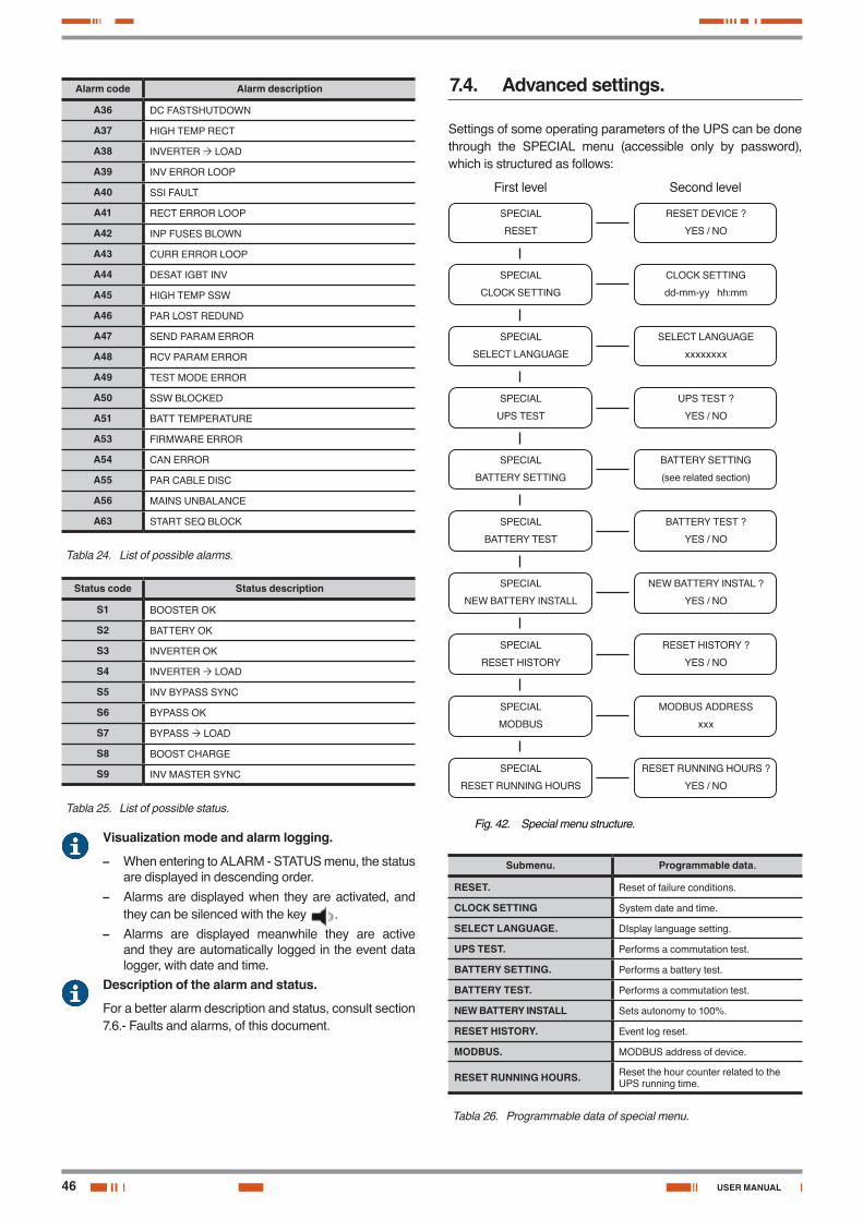
46
Alarm code Alarm description
A36 DC FASTSHUTDOWN
A37 HIGH TEMP RECT
A38 INVERTER LOAD
A39 INV ERROR LOOP
A40 SSI FAULT
A41 RECT ERROR LOOP
A42 INP FUSES BLOWN
A43 CURR ERROR LOOP
A44 DESAT IGBT INV
A45 HIGH TEMP SSW
A46 PAR LOST REDUND
A47 SEND PARAM ERROR
A48 RCV PARAM ERROR
A49 TEST MODE ERROR
A50 SSW BLOCKED
A51 BATT TEMPERATURE
A53 FIRMWARE ERROR
A54 CAN ERROR
A55 PAR CABLE DISC
A56 MAINS UNBALANCE
A63 START SEQ BLOCK
Tabla 24. List of possible alarms.
Status code Status description
S1 BOOSTER OK
S2 BATTERY OK
S3 INVERTER OK
S4 INVERTER LOAD
S5 INV BYPASS SYNC
S6 BYPASS OK
S7 BYPASS LOAD
S8 BOOST CHARGE
S9 INV MASTER SYNC
Tabla 25. List of possible status.
Visualization mode and alarm logging.
– When entering to ALARM - STATUS menu, the status are displayed in descending order.
– Alarms are displayed when they are activated, and they can be silenced with the key .
– Alarms are displayed meanwhile they are active and they are automatically logged in the event data logger, with date and time.
Description of the alarm and status.
For a better alarm description and status, consult section 7.6.- Faults and alarms, of this document.
7.4. Advanced settings.
Settings of some operating parameters of the UPS can be done through the SPECIAL menu (accessible only by password), which is structured as follows:
First level Second level
SPECIAL
RESET
SPECIAL
CLOCK SETTING
SPECIAL
SELECT LANGUAGE
SPECIAL
UPS TEST
SPECIAL
BATTERY SETTING
SPECIAL
BATTERY TEST
SPECIAL
NEW BATTERY INSTALL
SPECIAL
RESET HISTORY
SPECIAL
MODBUS
SPECIAL
RESET RUNNING HOURS
RESET DEVICE ?
YES / NO
CLOCK SETTING
dd-mm-yy hh:mm
SELECT LANGUAGE
xxxxxxxx
UPS TEST ?
YES / NO
BATTERY SETTING
(see related section)
BATTERY TEST ?
YES / NO
NEW BATTERY INSTAL ?
YES / NO
RESET HISTORY ?
YES / NO
MODBUS ADDRESS
xxx
RESET RUNNING HOURS ?
YES / NO
Fig. 42. Special menu structure.
Submenu. Programmable data.
RESET. Reset of failure conditions.
CLOCK SETTING System date and time.
SELECT LANGUAGE. DIsplay language setting.
UPS TEST. Performs a commutation test.
BATTERY SETTING. Performs a battery test.
BATTERY TEST. Performs a commutation test.
NEW BATTERY INSTALL Sets autonomy to 100%.
RESET HISTORY. Event log reset.
MODBUS. MODBUS address of device.
RESET RUNNING HOURS. Reset the hour counter related to the UPS running time.
Tabla 26. Programmable data of special menu.
USER MANUAL
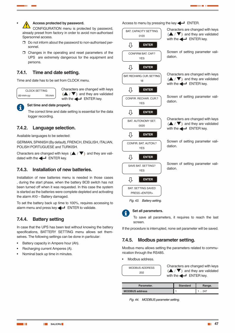
47SALICRU
• Access protected by password.CONFIGURATION menu is protected by password,
already preset from factory in order to avoid non-authorised Spersonnel access.
� Do not inform about the password to non-authorised per-sonnel.
� Changes in the operating and reset parameters of the UPS are extremely dangerous for the equipment and persons.
7.4.1. Time and date setting.Time and date has to be set from CLOCK menu.
CLOCK SETTING
dd-mm-yy hh:mm
Characters are changed with keys and they are validated
with the ENTER key.
Set time and date properly.
The correct time and date setting is essential for the data logger recording.
7.4.2. Language selection.Available languages to be selected:
GERMAN, SPANISH (By default), FRENCH, ENGLISH, ITALIAN, POLISH PORTUGUESE and TURKISH.
Characters are changed with keys and they are vali-dated with the ENTER key.
7.4.3. Installation of new batteries.Installation of new batteries menu is needed in those cases , during the start phase, when the battery BCB switch has not been turned off when it was requested. In this case the system is started as the batteries were complete depleted and activating the alarm A10 – Battery damaged.
To set the battery back up time to 100%, requires accessing to alarm menu and press key ENTER to validate.
7.4.4. Battery settingIn case that the UPS has been test without knowing the battery specifications, BATTERY SETTING menu allows set them-selves. The following settings can be done in particular:
• Battery capacity in Ampere hour (Ah).
• Recharging current Amperes (A).
• Nominal back up time in minutes.
Access to menu by pressing the key ENTER.
Characters are changed with keys and they are validated
with the ENTER key.
Screen of setting parameter vali-dation.
Characters are changed with keys and they are validated
with the ENTER key.
Screen of setting parameter vali-dation.
Characters are changed with keys and they are validated
with the ENTER key.
Screen of setting parameter vali-dation.
Screen of setting parameter vali-dation.
BAT. CAPACITY SETTING
0120
CONFIRM BAT. CAP.?
YES
BAT. RECHARG. CUR. SETTING
18
CONFIR. RECHAR. CUR.?
YES
BAT. AUTONOMY SET.
0020
CONFIR. BAT. AUTON.?
YES
SAVE BAT. SETTING?
YES
BAT. SETTING SAVED
PRESS <ENTER>
Fig. 43. Battery setting.
Set all parameters.
To save all parameters, it requires to reach the last screen.
If the procedure is interrupted, none set parameter will be saved.
7.4.5. Modbus parameter setting.Modbus menu allows setting the parameters related to commu-nication through the RS485.
• Modbus address.
MODBUS ADDRESS
202
Characters are changed with keys and they are validated
with the ENTER key.
Parameter. Standard Range.
MODBUS address 1 1 ... 247
Fig. 44. MODBUS parameter setting.
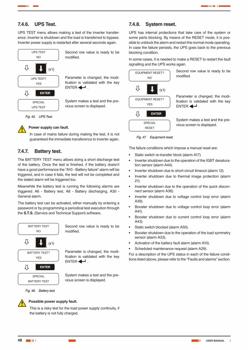
48
7.4.6. UPS Test.UPS TEST menu allows making a test of the inverter transfer-ence. Inverter is shutdown and the load is transferred to bypass. Inverter power supply is restarted after several seconds again.
Second row value is ready to be modified.
Parameter is changed, the modi-fication is validated with the key ENTER .
System makes a test and the pre-vious screen is displayed.
UPS TEST
NO
UPS TEST?
YES
SPECIAL
UPS TEST
(x1)
Fig. 45. UPS Test.
Power supply can fault.
In case of mains failure during making the test, it is not guaranteed the immediate transference to inverter again.
7.4.7. Battery test.The BATTERY TEST menu allows doing a short discharge test of the battery. Once the test is finished, if the battery doesn't have a good performance the "A10 - Battery failure" alarm will be triggered, and in case it fails, the test will not be completed and the stated alarm will be triggered too.
Meanwhile the battery test is running the following alarms are triggered: A6 - Battery test, A8 - Battery discharging, A30 - General alarm.
The battery test can be activated, either manually by entering a password or by programming a periodical test execution through the S.T.S. (Service and Technical Support) software.
Second row value is ready to be modified.
Parameter is changed, the modi-fication is validated with the key ENTER .
System makes a test and the pre-vious screen is displayed.
BATTERY TEST
NO
BATTERY TEST?
YES
SPECIAL
BATTERY TEST
(x1)
Fig. 46. Battery test.
Possible power supply fault.
This is a risky test for the load power supply continuity, if the battery is not fully charged.
7.4.8. System reset.UPS has internal protections that take care of the system or some parts blocking. By means of the RESET mode, it is pos-sible to unblock the alarm and restart the normal mode operating. In case the failure persists, the UPS goes back to the previous blocking condition.
In some cases, it is needed to make a RESET to restart the fault signalling and the UPS works again.
Second row value is ready to be modified.
Parameter is changed, the modi-fication is validated with the key ENTER .
System makes a test and the pre-vious screen is displayed.
EQUIPMENT RESET?
NO
EQUIPMENT RESET?
YES
SPECIAL
RESET
(x1)
Fig. 47. Equipment reset.
The failure conditions which impose a manual reset are:
• Static switch re-transfer block (alarm A17).
• Inverter shutdown due to the operation of the IGBT desatura-tion sensor (alarm A44).
• Inverter shutdown due to short-circuit timeout (alarm 12).
• Inverter shutdown due to thermal image protection (alarm 21).
• Inverter shutdown due to the operation of the quick discon-nect sensor (alarm A36).
• Inverter shutdown due to voltage control loop error (alarm A39).
• Booster shutdown due to voltage control loop error (alarm A41).
• Booster shutdown due to current control loop error (alarm A43).
• Static switch blocked (alarm A50).
• Booster shutdown due to the operation of the load symmetry sensor (alarm A33).
• Activation of the battery fault alarm (alarm A10).
• Scheduled maintenance request (alarm A29).For a description of the UPS status in each of the failure condi-tions listed above, please refer to the “Faults and alarms” section.
USER MANUAL
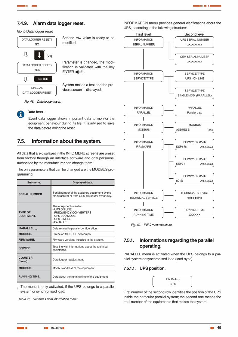
49SALICRU
7.4.9. Alarm data logger reset.Go to Data logger reset
Second row value is ready to be modified.
Parameter is changed, the modi-fication is validated with the key ENTER .
System makes a test and the pre-vious screen is displayed.
DATA LOGGER RESET?
NO
DATA LOGGER RESET?
YES
SPECIAL
DATA LOGGER RESET
(x1)
Fig. 48. Data logger reset.
Data loss.
Event data logger shows important data to monitor the equipment behaviour during its life. It is advised to save the data before doing the reset.
7.5. Information about the system.
All data that are displayed in the INFO MENU screens are preset from factory through an interface software and only personnel authorised by the manufacturer can change them.
The only parameters that can be changed are the MODBUS pro-gramming.
Submenu. Displayed data.
SERIAL NUMBER. Serial number of the assigned equipment by the manufacturer or from OEM distributor eventually.
TYPE OF EQUIPMENT.
The equipments can be:- UPS ON LINE- FREQUENCY CONVERTERS- UPS ECO MODE- UPS SINGLE- PARALLEL
PARALLEL (1). Data related to parallel configuration.
MODBUS. Dirección MODBUS del equipo.
FIRMWARE. Firmware versions installed in the system.
SERVICE. Test line with informations about the technical assistance.
COUNTER(timer). Data logger readjustment.
MODBUS. Modbus address of the equipment.
RUNNING TIME. Data about the running time of the equipment.
(1) The menu is only activated, if the UPS belongs to a parallel system or synchronised load.
Tabla 27. Variables from information menu.
INFORMATION menu provides general clarifications about the UPS, according to the following structure:
First level Second levelINFORMATION
SERIAL NUMBER
INFORMATION
PARALLEL
UPS SERIAL NUMBER
xxxxxxxxxx
PARALLEL
Parallel date
OEM SERIAL NUMBER
xxxxxxxxxx
INFORMATION
SERVICE TYPE
SERVICE TYPE
UPS - ON LINE
SERVICE TYPE
SINGLE MOD. (PARALLEL)
INFORMATION
MODBUS
MODBUS
ADDRESS: xxx
INFORMATION
FIRMWARE
FIRMWARE DATE
DSP1 R: vv.xx.yy.zz
FIRMWARE DATE
DSP2 I: vv.xx.yy.zz
FIRMWARE DATE
uC S: vv.xx.yy.zz
INFORMATION
TECHNICAL SERVICE
TECHNICAL SERVICE
text slipping
INFORMATION
RUNNING TIME
RUNNING TIME
XXXXXX
Fig. 49. INFO menu structure.
7.5.1. Informations regarding the parallel operating.
PARALLEL menu is activated when the UPS belongs to a par-allel system or synchronised load (load-sync).
7.5.1.1. UPS position.
PARALLEL
2 / 6
First number of the second row identifies the position of the UPS inside the particular parallel system; the second one means the total number of the equipments that makes the system.
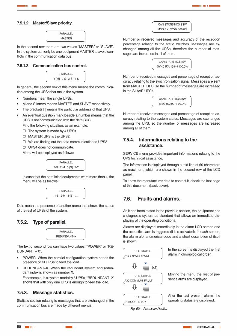
50
7.5.1.2. Master/Slave priority.
PARALLEL
MASTER
In the second row there are two values “MASTER” or “SLAVE”. In the system can only be one equipment MASTER to avoid con-flicts in the communication data bus.
7.5.1.3. Communication bus control.
PARALLEL
1-[M] 2-S 3-S 4-S
In general, the second row of this menu means the communica-tion among the UPSs that make the system.
• Numbers mean the single UPSs.
• M and S letters means MASTER and SLAVE respectively.
• The brackets [ ] means the particular address of that UPS.
• An eventual question mark beside a number means that the UPS is not communicated with the data BUS.
Find the following situation, as an example:
� The system is made by 4 UPSs.
� MASTER UPS is the UPS2.
� We are finding out the data communication to UPS3.
� UPS4 does not communicate.
Menu will be displayed as follows:
PARALLEL
1-S 2-M 3-[S] 4-?
In case that the paralleled equipments were more than 4, the menu will be as follows:
PARALLEL
1-S 2-M 3-[S] ....
Dots mean the presence of another menu that shows the status of the rest of UPSs of the system.
7.5.2. Type of parallel.
PARALLEL
REDUNDANT+X
The text of second row can have two values, “POWER” or “RE-DUNDANT + X”.
• POWER. When the parallel configuration system needs the presence of all UPSs to feed the load.
• REDUNDANT+X. When the redundant system and redun-dant index is shown as number X.
For example, in a system made by 3 UPSs, “REDUNDANT+2” shows that with only one UPS is enough to feed the load.
7.5.3. Message statistics.Statistic section relating to messages that are exchanged in the communication bus are made by different menus.
CAN STATISTICS SSW
MSG RX: 32564 100.0%
Number or received messages and accuracy of the reception percentage relating to the static switches. Messages are ex-changed among all the UPSs, therefore the number of mes-sages are increased in all of them.
CAN STATISTICS INV
SYNC RX: 15849 100.0%
Number of received messages and percentage of reception ac-curacy relating to the synchronisation signal. Messages are sent from MASTER UPS, so the number of messages are increased in the SLAVE UPSs.
CAN STATISTICS INV
MSG RX: 9277 99.9%
Number of received messages and percentage of reception ac-curacy relating to the system status. Messages are exchanged among the UPS, so the number of messages are increased among all of them.
7.5.4. Informations relating to the assistance.
SERVICE menu provides important informations relating to the UPS technical assistance.
The information is displayed through a text line of 60 characters as maximum, which are shown in the second row of the LCD panel.
To know the manufacturer data to contact it, check the last page of this document (back cover).
7.6. Faults and alarms.
As it has been stated in the previous section, the equipment has a diagnosis system as standard that allows an immediate dis-playing of the operating conditions.
Alarms are displayed immediately in the alarm LCD screen and the acoustic alarm is triggered (if it is activated). In each screen, the alarm alphanumerical code and a short description of itself is shown.
UPS STATUS
A15 BYPASS FAULT
In the screen is displayed the first alarm in chronological order.
(x1)
UPS STATUS
A30 COMMUN. FAULT
Moving the menu the rest of pre-sent alarms are displayed.
UPS STATUS
S1 BOOSTER OK
After the last present alarm, the operating status are displayed.
Fig. 50. Alarms and faults.
USER MANUAL
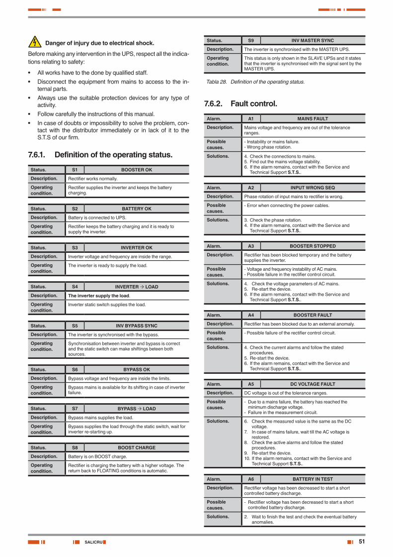
51SALICRU
Danger of injury due to electrical shock.
Before making any intervention in the UPS, respect all the indica-tions relating to safety:
• All works have to the done by qualified staff.
• Disconnect the equipment from mains to access to the in-ternal parts.
• Always use the suitable protection devices for any type of activity.
• Follow carefully the instructions of this manual.
• In case of doubts or impossibility to solve the problem, con-tact with the distributor immediately or in lack of it to the S.T.S of our firm.
7.6.1. Definition of the operating status.
Status. S1 BOOSTER OK
Description. Rectifier works normally.
Operating condition.
Rectifier supplies the inverter and keeps the battery charging.
Status. S2 BATTERY OK
Description. Battery is connected to UPS.
Operating condition.
Rectifier keeps the battery charging and it is ready to supply the inverter.
Status. S3 INVERTER OK
Description. Inverter voltage and frequency are inside the range.
Operating condition.
The inverter is ready to supply the load.
Status. S4 INVERTER LOAD
Description. The inverter supply the load.
Operating condition.
Inverter static switch supplies the load.
Status. S5 INV BYPASS SYNC
Description. The inverter is synchronised with the bypass.
Operating condition.
Synchronisation between inverter and bypass is correct and the static switch can make shiftings beteen both sources.
Status. S6 BYPASS OK
Description. Bypass voltage and frequency are inside the limits.
Operating condition.
Bypass mains is available for its shifting in case of inverter failure.
Status. S7 BYPASS LOAD
Description. Bypass mains supplies the load.
Operating condition.
Bypass supplies the load through the static switch, wait for inverter re-starting up.
Status. S8 BOOST CHARGE
Description. Battery is on BOOST charge.
Operating condition.
Rectifier is charging the battery with a higher voltage. The return back to FLOATING conditions is automatic.
Status. S9 INV MASTER SYNC
Description. The inverter is synchronised with the MASTER UPS.
Operating condition.
This status is only shown in the SLAVE UPSs and it states that the inverter is synchronised with the signal sent by the MASTER UPS.
Tabla 28. Definition of the operating status.
7.6.2. Fault control.
Alarm. A1 MAINS FAULT
Description. Mains voltage and frequency are out of the tolerance ranges.
Possible causes.
- Instability or mains failure.- Wrong phase rotation.
Solutions. 4. Check the connections to mains.5. Find out the mains voltage stability.6. If the alarm remains, contact with the Service and
Technical Support S.T.S..
Alarm. A2 INPUT WRONG SEQ
Description. Phase rotation of input mains to rectifier is wrong.
Possible causes.
- Error when connecting the power cables.
Solutions. 3. Check the phase rotation.4. If the alarm remains, contact with the Service and
Technical Support S.T.S..
Alarm. A3 BOOSTER STOPPED
Description. Rectifier has been blocked temporary and the battery supplies the inverter.
Possible causes.
- Voltage and frequency instability of AC mains.- Possible failure in the rectifier control circuit.
Solutions. 4. Check the voltage parameters of AC mains.5. Re-start the device.6. If the alarm remains, contact with the Service and
Technical Support S.T.S..
Alarm. A4 BOOSTER FAULT
Description. Rectifier has been blocked due to an external anomaly.
Possible causes.
- Possible failure of the rectifier control circuit.
Solutions. 4. Check the current alarms and follow the stated procedures.
5. Re-start the device.6. If the alarm remains, contact with the Service and
Technical Support S.T.S..
Alarm. A5 DC VOLTAGE FAULT
Description. DC voltage is out of the tolerance ranges.
Possible causes.
- Due to a mains failure, the battery has reached the minimum discharge voltage.
- Failure in the measurement circuit.
Solutions. 6. Check the measured value is the same as the DC voltage.
7. In case of mains failure, wait till the AC voltage is restored.
8. Check the active alarms and follow the stated procedures.
9. Re-start the device.10. If the alarm remains, contact with the Service and
Technical Support S.T.S..
Alarm. A6 BATTERY IN TEST
Description. Rectifier voltage has been decreased to start a short controlled battery discharge.
Possible causes.
- Rectifier voltage has been decreased to start a short controlled battery discharge.
Solutions. 2. Wait to finish the test and check the eventual battery anomalies.
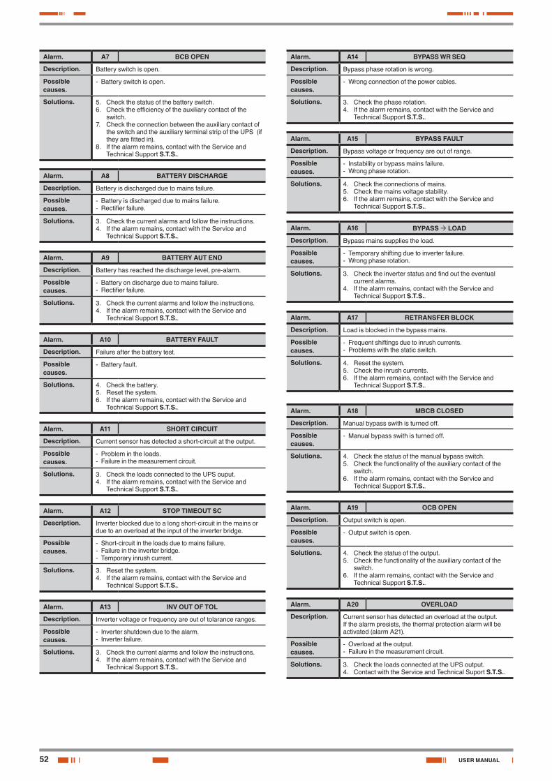
52
Alarm. A7 BCB OPEN
Description. Battery switch is open.
Possible causes.
- Battery switch is open.
Solutions. 5. Check the status of the battery switch.6. Check the efficiency of the auxiliary contact of the
switch.7. Check the connection between the auxiliary contact of
the switch and the auxiliary terminal strip of the UPS (if they are fitted in).
8. If the alarm remains, contact with the Service and Technical Support S.T.S..
Alarm. A8 BATTERY DISCHARGE
Description. Battery is discharged due to mains failure.
Possible causes.
- Battery is discharged due to mains failure.- Rectifier failure.
Solutions. 3. Check the current alarms and follow the instructions.4. If the alarm remains, contact with the Service and
Technical Support S.T.S..
Alarm. A9 BATTERY AUT END
Description. Battery has reached the discharge level, pre-alarm.
Possible causes.
- Battery on discharge due to mains failure.- Rectifier failure.
Solutions. 3. Check the current alarms and follow the instructions.4. If the alarm remains, contact with the Service and
Technical Support S.T.S..
Alarm. A10 BATTERY FAULT
Description. Failure after the battery test.
Possible causes.
- Battery fault.
Solutions. 4. Check the battery.5. Reset the system.6. If the alarm remains, contact with the Service and
Technical Support S.T.S..
Alarm. A11 SHORT CIRCUIT
Description. Current sensor has detected a short-circuit at the output.
Possible causes.
- Problem in the loads.- Failure in the measurement circuit.
Solutions. 3. Check the loads connected to the UPS ouput.4. If the alarm remains, contact with the Service and
Technical Support S.T.S..
Alarm. A12 STOP TIMEOUT SC
Description. Inverter blocked due to a long short-circuit in the mains or due to an overload at the input of the inverter bridge.
Possible causes.
- Short-circuit in the loads due to mains failure.- Failure in the inverter bridge.- Temporary inrush current.
Solutions. 3. Reset the system.4. If the alarm remains, contact with the Service and
Technical Support S.T.S..
Alarm. A13 INV OUT OF TOL
Description. Inverter voltage or frequency are out of tolarance ranges.
Possible causes.
- Inverter shutdown due to the alarm.- Inverter failure.
Solutions. 3. Check the current alarms and follow the instructions.4. If the alarm remains, contact with the Service and
Technical Support S.T.S..
Alarm. A14 BYPASS WR SEQ
Description. Bypass phase rotation is wrong.
Possible causes.
- Wrong connection of the power cables.
Solutions. 3. Check the phase rotation.4. If the alarm remains, contact with the Service and
Technical Support S.T.S..
Alarm. A15 BYPASS FAULT
Description. Bypass voltage or frequency are out of range.
Possible causes.
- Instability or bypass mains failure.- Wrong phase rotation.
Solutions. 4. Check the connections of mains.5. Check the mains voltage stability.6. If the alarm remains, contact with the Service and
Technical Support S.T.S..
Alarm. A16 BYPASS LOAD
Description. Bypass mains supplies the load.
Possible causes.
- Temporary shifting due to inverter failure.- Wrong phase rotation.
Solutions. 3. Check the inverter status and find out the eventual current alarms.
4. If the alarm remains, contact with the Service and Technical Support S.T.S..
Alarm. A17 RETRANSFER BLOCK
Description. Load is blocked in the bypass mains.
Possible causes.
- Frequent shiftings due to inrush currents.- Problems with the static switch.
Solutions. 4. Reset the system.5. Check the inrush currents.6. If the alarm remains, contact with the Service and
Technical Support S.T.S..
Alarm. A18 MBCB CLOSED
Description. Manual bypass swith is turned off.
Possible causes.
- Manual bypass swith is turned off.
Solutions. 4. Check the status of the manual bypass switch.5. Check the functionality of the auxiliary contact of the
switch.6. If the alarm remains, contact with the Service and
Technical Support S.T.S..
Alarm. A19 OCB OPEN
Description. Output switch is open.
Possible causes.
- Output switch is open.
Solutions. 4. Check the status of the output.5. Check the functionality of the auxiliary contact of the
switch.6. If the alarm remains, contact with the Service and
Technical Support S.T.S..
Alarm. A20 OVERLOAD
Description. Current sensor has detected an overload at the output. If the alarm presists, the thermal protection alarm will be activated (alarm A21).
Possible causes.
- Overload at the output.- Failure in the measurement circuit.
Solutions. 3. Check the loads connected at the UPS output.4. Contact with the Service and Technical Suport S.T.S..
USER MANUAL

53SALICRU
Alarm. A21 THERMAL IMAGE
Description. Thermal protection has been activated after a long inverter overload.
Possible causes.
- Overload at the output.- Failure in the measurement circuit.
Solutions. 4. Check the loads connected at the UPS output.5. To re-start the power supply from the inverter, reset the
sytem.6. If the alarm remains, contact with the Service and
Technical Support S.T.S..
Alarm. A22 BYPASS SWITCH
Description. Position of "Normal/Bypass" selector has been changed.
Possible causes.
- Action for maintenance.
Solutions. 3. Check the position of the selector.4. If the alarm remains, contact with the Service and
Technical Support S.T.S..
Alarm. A23 EPO PRESSED
Description. System is blocked due to the activation of the emergency power off button.
Possible causes.
- Activation of the emergency power button (local or remote).
Solutions. 3. Emergency power off unblocking and reset the alarm.4. If the alarm remains, contact with the Service and
Technical Support S.T.S..
Alarm. A24 HITMP INV/DC FUS
Description. High temperature of the inverter bridge heatsink or DC fuses from inverter bridge has been blown .
Possible causes.
- Failure in the fans of the heatsink cooling system.- Ambient temperature or cooling air are too high.- Protection DC fuses have been blown.
Solutions. 6. Check the fan operation.7. Clean the cooling grids and the eventual air filters.8. Check the air conditioning system (in case there is
anyone).9. Check the status of the input DC fuses from inverter
bridge.10. If the alarm remains, contact with the Service and
Technical Support S.T.S..
Alarm. A25 INVERTER OFF
Description. The inverter is blocked due to wrong operation.
Possible causes.
- Various.
Solutions. 3. Reset the system.4. If the alarm remains, contact with the Service and
Technical Support S.T.S..
Alarm. A26 COMMUNIC ERROR.
Description. Internal error.
Possible causes.
- Communication problems of the microcontroller.
Solutions. 2. If the alarm remains, contact with the Service and Technical Support S.T.S..
Alarm. A27 COMMUNIC ERROR
Description. The controller has detected an error in the parameters stored in the E2PROM.
Possible causes.
- Wrong parameters are inserted during the programming.
Solutions. 2. If the alarm remains, contact with the Service and Technical Support S.T.S..
Alarm. A28 CRITICAL FAULT
Description. An alarm is activated due to blocking of any UPS part (rectifier, inverter, static switch).
Possible causes.
- System failure.
Solutions. 3. Check the current alarms and follow the stated procedure.
4. If the alarm remains, contact with the Service and Technical Support S.T.S..
Alarm. A29 MAINTENANCE REQ
Description. Maintenance is needed.
Possible causes.
- The period of time since the last maintenance has been exceeded.
Solutions. 2. Contact with the Service and Technical Support S.T.S..
Alarm. A30 COMMON ALARM
Description. Accumulative alarm.
Possible causes.
- One alarm has been activated at least
Solutions. 2. Check the current alarms and follow the indications.
Alarm. A31 MBCB BUS CLOSED
Description. Manual bypass switch is closed.
Possible causes.
- Manual bypass switch is closed.
Solutions. 4. Check the status of the manual bypass switch.5. Check the functionality of the auxiliary contact of the
switch.6. If the alarm remains, contact with the Service and
Technical Support S.T.S..
Alarm. A32 EPO BUS CLOSED
Description. System is blocked due to an activation of the emergency button.
Possible causes.
- Activation of the emergency power off button (local or remote).
Solutions. 3. Unblock the emergency button and reset the alarm.4. If the alarm remains, contact with the Service and
Technical Support S.T.S..
Alarm. A33 ASYMMETRIC LOAD
Description. Voltage measured in the DC capacitors (positive and negative referred to the central point) are different.
Possible causes.
- Possible failure in the measure circuit.- Possible failure of the DC capacitors.
Solutions. 3. Reset the system.4. If the alarm remains, contact with the Service and
Technical Support S.T.S..
Alarm. A34 SERVICE REQUIRED
Description. It is needed a UPS inspection.
Possible causes.
- Possible UPS failure.- Possible failure of the DC capacitors.
Solutions. 2. If the alarm remains, contact with the Service and Technical Support S.T.S..
Alarm. A35 DIESEL MODE
Description. UPS is supplied by a diesel genset.
Possible causes.
- Auxiliary contact from diesel genset, connected to the UPS, is closed and forces the UPS to this operating mode.
Solutions. 4. Wait for diesel genset blocking when mains is restored.
5. Check the auxiliary contact connection from the diesel genset to terminal strip XD1/XD-2.
6. If the alarm remains, contact with the Service and Technical Support S.T.S..
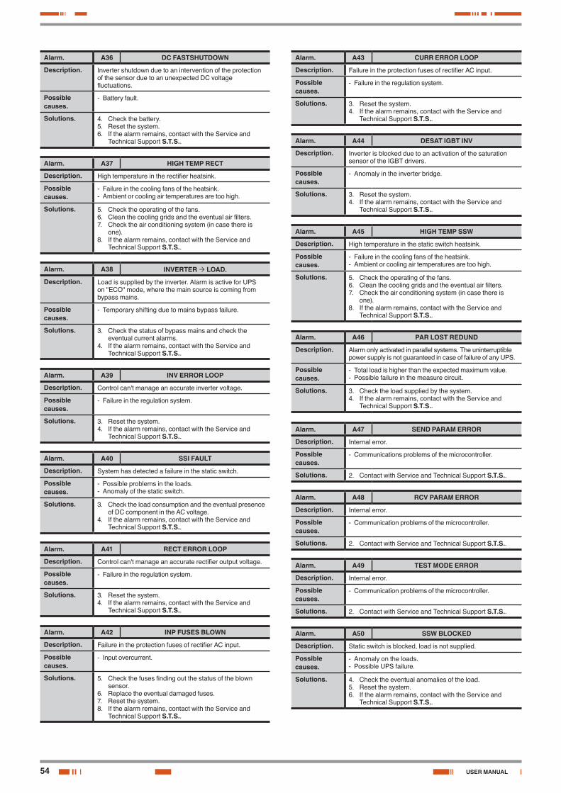
54
Alarm. A36 DC FASTSHUTDOWN
Description. Inverter shutdown due to an intervention of the protection of the sensor due to an unexpected DC voltage fluctuations.
Possible causes.
- Battery fault.
Solutions. 4. Check the battery.5. Reset the system.6. If the alarm remains, contact with the Service and
Technical Support S.T.S..
Alarm. A37 HIGH TEMP RECT
Description. High temperature in the rectifier heatsink.
Possible causes.
- Failure in the cooling fans of the heatsink.- Ambient or cooling air temperatures are too high.
Solutions. 5. Check the operating of the fans.6. Clean the cooling grids and the eventual air filters.7. Check the air conditioning system (in case there is
one).8. If the alarm remains, contact with the Service and
Technical Support S.T.S..
Alarm. A38 INVERTER LOAD.
Description. Load is supplied by the inverter. Alarm is active for UPS on "ECO" mode, where the main source is coming from bypass mains.
Possible causes.
- Temporary shifting due to mains bypass failure.
Solutions. 3. Check the status of bypass mains and check the eventual current alarms.
4. If the alarm remains, contact with the Service and Technical Support S.T.S..
Alarm. A39 INV ERROR LOOP
Description. Control can't manage an accurate inverter voltage.
Possible causes.
- Failure in the regulation system.
Solutions. 3. Reset the system.4. If the alarm remains, contact with the Service and
Technical Support S.T.S..
Alarm. A40 SSI FAULT
Description. System has detected a failure in the static switch.
Possible causes.
- Possible problems in the loads.- Anomaly of the static switch.
Solutions. 3. Check the load consumption and the eventual presence of DC component in the AC voltage.
4. If the alarm remains, contact with the Service and Technical Support S.T.S..
Alarm. A41 RECT ERROR LOOP
Description. Control can't manage an accurate rectifier output voltage.
Possible causes.
- Failure in the regulation system.
Solutions. 3. Reset the system.4. If the alarm remains, contact with the Service and
Technical Support S.T.S..
Alarm. A42 INP FUSES BLOWN
Description. Failure in the protection fuses of rectifier AC input.
Possible causes.
- Input overcurrent.
Solutions. 5. Check the fuses finding out the status of the blown sensor.
6. Replace the eventual damaged fuses.7. Reset the system.8. If the alarm remains, contact with the Service and
Technical Support S.T.S..
Alarm. A43 CURR ERROR LOOP
Description. Failure in the protection fuses of rectifier AC input.
Possible causes.
- Failure in the regulation system.
Solutions. 3. Reset the system.4. If the alarm remains, contact with the Service and
Technical Support S.T.S..
Alarm. A44 DESAT IGBT INV
Description. Inverter is blocked due to an activation of the saturation sensor of the IGBT drivers.
Possible causes.
- Anomaly in the inverter bridge.
Solutions. 3. Reset the system.4. If the alarm remains, contact with the Service and
Technical Support S.T.S..
Alarm. A45 HIGH TEMP SSW
Description. High temperature in the static switch heatsink.
Possible causes.
- Failure in the cooling fans of the heatsink.- Ambient or cooling air temperatures are too high.
Solutions. 5. Check the operating of the fans.6. Clean the cooling grids and the eventual air filters.7. Check the air conditioning system (in case there is
one).8. If the alarm remains, contact with the Service and
Technical Support S.T.S..
Alarm. A46 PAR LOST REDUND
Description. Alarm only activated in parallel systems. The uninterruptible power supply is not guaranteed in case of failure of any UPS.
Possible causes.
- Total load is higher than the expected maximum value.- Possible failure in the measure circuit.
Solutions. 3. Check the load supplied by the system.4. If the alarm remains, contact with the Service and
Technical Support S.T.S..
Alarm. A47 SEND PARAM ERROR
Description. Internal error.
Possible causes.
- Communications problems of the microcontroller.
Solutions. 2. Contact with Service and Technical Support S.T.S..
Alarm. A48 RCV PARAM ERROR
Description. Internal error.
Possible causes.
- Communication problems of the microcontroller.
Solutions. 2. Contact with Service and Technical Support S.T.S..
Alarm. A49 TEST MODE ERROR
Description. Internal error.
Possible causes.
- Communication problems of the microcontroller.
Solutions. 2. Contact with Service and Technical Support S.T.S..
Alarm. A50 SSW BLOCKED
Description. Static switch is blocked, load is not supplied.
Possible causes.
- Anomaly on the loads.- Possible UPS failure.
Solutions. 4. Check the eventual anomalies of the load.5. Reset the system.6. If the alarm remains, contact with the Service and
Technical Support S.T.S..
USER MANUAL
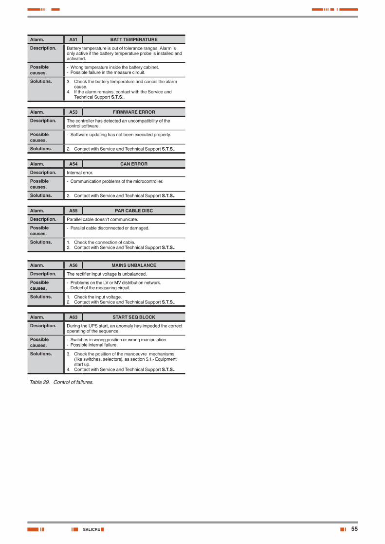
55SALICRU
Alarm. A51 BATT TEMPERATURE
Description. Battery temperature is out of tolerance ranges. Alarm is only active if the battery temperature probe is installed and activated.
Possible causes.
- Wrong temperature inside the battery cabinet.- Possible failure in the measure circuit.
Solutions. 3. Check the battery temperature and cancel the alarm cause.
4. If the alarm remains, contact with the Service and Technical Support S.T.S..
Alarm. A53 FIRMWARE ERROR
Description. The controller has detected an uncompatibility of the control software.
Possible causes.
- Software updating has not been executed properly.
Solutions. 2. Contact with Service and Technical Support S.T.S..
Alarm. A54 CAN ERROR
Description. Internal error.
Possible causes.
- Communication problems of the microcontroller.
Solutions. 2. Contact with Service and Technical Support S.T.S..
Alarm. A55 PAR CABLE DISC
Description. Parallel cable doesn't communicate.
Possible causes.
- Parallel cable disconnected or damaged.
Solutions. 1. Check the connection of cable.2. Contact with Service and Technical Support S.T.S..
Alarm. A56 MAINS UNBALANCE
Description. The rectifier input voltage is unbalanced.
Possible causes.
- Problems on the LV or MV distribution network.- Defect of the measuring circuit.
Solutions. 1. Check the input voltage.2. Contact with Service and Technical Support S.T.S..
Alarm. A63 START SEQ BLOCK
Description. During the UPS start, an anomaly has impeded the correct operating of the sequence.
Possible causes.
- Switches in wrong position or wrong manipulation.- Possible internal failure.
Solutions. 3. Check the position of the manoeuvre mechanisms (like switches, selectors), as section 5.1.- Equipment start up.
4. Contact with Service and Technical Support S.T.S..
Tabla 29. Control of failures.
56
8. Maintenance, warranty and service.
8.1. Basic maintenance guide.
Batteries, fans and capacitors must be replaced at the end of their useful lifetime.
Inside the UPS there are dangerous voltages and me-tallic parts at very high temperatures, although the UPS
is shutdown. The direct contact can cause electrocutions and burns. All the operating, less the battery fuse replacing, must be done by authorised technical staff.
Some internal parts of the UPS (terminals, EMC filters and measurement circuits) are still under voltage during
the maintenance bypass operating. To cancel all the voltages, the circuit breakers of mains and bypass of the panel that feeds the UPS and the fuse holders of the external battery cabinet have to be turned «OFF» / «0».
8.1.1. Batteries.The useful lifetime of the batteries depends on the ambient tem-perature and other factors like the quantity of charging and dis-charging cycles and the deep discharges done.
The average lifetime is 10 years if the ambient temperature is between 10 and 20ºC. To have more information of its status, activate the battery test.
Risk of fire and/or explosion exists if a wrong quantity or type of batteries is used. Pay attention to all indications
relating to batteries in this document and in particular to section 5.1.1.- Safety instructions relating to batteries.
8.1.2. Fans.The useful lifetime of the used fans to cool the power circuits depends on the use and environment conditions. It is recommended their preventive replacement by authorised technical staff.
8.1.3. Capacitors.The useful lifetime of the DC bus capacitors and those ones used in the input and output filtering depends on the use and the environment conditions. It is recommended their preventive replacement by authorised technical staff.
8.2. WARRANTY CONDITIONS.
8.2.1. Warranty terms.The warranty conditions for the acquired product can be found in our website and in that you will be able to register it. It is recommended to do it as soon as possible in order to include it in the Technical Service & Support (T.S.S.) database. Among other advantages, it will be easier to make any regulatory process to allow the S.T.S action in case of any hypothetical fault.
8.2.2. Out of scope of supply.Our company is not forced by the warranty if it appreciates that the defect in the product doesn’t exist or it was caused by a wrong use, negligence, installation and/or inadequate testing, tentative of non-authorised repairing or modification, or any other cause beyond the foreseen use, or by accident, fire, lightnings or other dangers. Neither it will cover, in any case, compensations for damages or injuries.
8.3. Technical service network.
Coverage, both national and international, from our Technical Service & Support (T.S.S.), can be found in our Website.
USER MANUAL
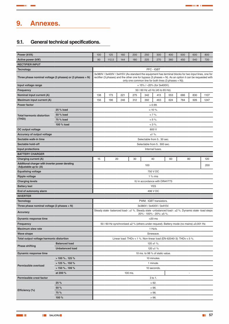
57SALICRU
9. Annexes.
9.1. General technical specifications.
Power (kVA) 100 125 160 200 250 300 400 500 600 800
Active power (kW) 90 112,5 144 180 225 270 360 450 540 720
RECTIFIER INPUT
Tecnology PFC - IGBT
Three phase nominal voltage (3 phases) or (3 phases + N)3x380V / 3x400V / 3x415V (As standard the equipment has terminal blocks for two input lines, one for rectifier (3 phases) and the other one for bypass (3 phases + N). As an option it can be requested with
only one common line for both lines (3 phases + N)).
Input voltage range + 15% / –20% (for 3x400V).
Frequency 50 / 60 Hz ±5 Hz (45 to 65 Hz).
Nominal input current (A) 138 173 221 275 342 413 553 686 830 1107
Maximum input current (A) 156 196 246 312 392 463 624 784 926 1247
Power factor > 0.99.
Total harmonic distortion (THDi)
25 % load < 10 %.
50 % load < 7 %.
75 % load < 5 %.
100 % load < 3 %.
DC output voltage 600 V
Accuracy of output voltage ±1 %.
Sectable walk-in time Selectable from 5.. 30 sec.
Sectable hold-off Selectable from 5.. 300 sec.
Input protections Internal fuses.
BATTERY CHARGER
Charging current (A) 15 20 30 40 60 80 120
Additional charger with inverter power derating-Adjustable up to- (A) 100 200
Equalising voltage 750 V DC
Ripple voltage 1 % rms
Charging levels IU in accordance with DIN41773
Battery test YES
End of autonomy alarm 496 V DC
INVERTER
Tecnology PWM; IGBT transistors.
Three phase nominal voltage (3 phases + N) 3x380V / 3x400V / 3x415V.
Accuracy Steady state -balanced load-: ±1 %. Steady state -unbalanced load-: ±2 %. Dynamic state -load steps 20% - 100% - 20%: ±5 %.
Dynamic response time <20 ms
Frequency 50 / 60 Hz synchronised ±2 % (others under request). Battery mode (no mains) ±0,001 Hz.
Maximum slew rate 1 Hz/s.
Wave shape Sinewave.
Total output voltage harmonic distortion Linear load: THDv < 1 %. Non-linear load (EN-62040-3): THDv < 5 %.
Phase shiftingBalanced load 120 ±1 %.
Unbalanced load 120 ±1 %
Dynamic response time 10 ms. to 98 % of static value.
Permissible overload
> 100 %.. 125 % 10 minutes.
> 125 %.. 150 % 1 minute.
> 150 %.. 199 % 10 seconds.
at 200 % 100 ms. -
Permissible crest factor 3 to 1.
Efficiency (%)
25 % > 92.
50 % > 96.
75 % > 96.
100 % > 96.
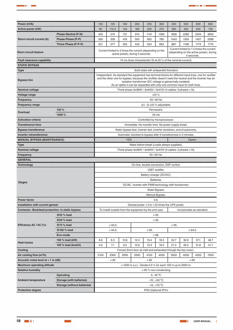
58
Power (kVA) 100 125 160 200 250 300 400 500 600 800
Active power (kW) 90 112,5 144 180 225 270 360 450 540 720
Short-circuit current (A)
Phase-Neutral (P-N) 455 570 731 910 1141 1365 1826 2282 2424 3652
Phase-Phase (P-P) 260 326 418 520 652 780 1043 1304 1407 2086
Three-Phase (P-P-P) 221 277 355 442 554 663 887 1108 1173 1774
Short-circuit feature Current limited to 2 times the current (depending on the active power), during 5 seconds.
Current limited to 1.5 times the current (depending on the active power), during
5 seconds.
Fault clearance capability 10 ms (fuse characteristic Gl at 20 % of the nominal current).
STATIC BYPASS
Type Solid state with antiparallel thyristors
Bypass line
Independent. As standard the equipment has terminal blocks for different input lines, one for rectifier and the other one for bypass, because the rectifier doesn't need the neutral and the inverter has an
isolation transformer (DC voltage is galvanivally isolated). As an option it can be requested with only one common input for both lines.
Nominal voltage Three phase 3x380V / 3x400V / 3x415V (4 cables: 3 phases + N).
Voltage range ±10 %
Frequency 50 / 60 Hz
Frequency range ±(1.. 5) ±10 % adjustable.
Overload150 % Permanent.
1000 % 20 ms
Activation criteria Controlled by microprocessor.
Transference time Immediate. No transfer time. No power supply break.
Bypass transference Static bypass test, inverter test, inverter shutdown, end of autonomy.
Inverter retransference Automatic; blocked to bypass after 6 transferences in 2 minutes.
MANUAL BYPASS (MAINTENANCE) YES Option
Type Make before break (Loads always supplied).
Nominal voltage Three phase 3x380V / 3x400V / 3x415V (4 cables: 3 phases + N).
Frequency 50 / 60 Hz.
GENERAL
Technology On-line, double conversion, DSP control.
Stages
IGBT rectifier.
Battery charger (DC/DC).
Batteries.
DC/AC inverter with PWM technology with transformer.
Static Bypass.
Manual Bypass.
Power factor 0.9.
Installation with current genset Genset power 1,2 to 1,25 times the UPS power.
Contactor -Backfeed protection- in static bypass To install outside from the equipment by the end-user. Incorporates as standard.
Efficiency AC / AC (%)
@25 % load > 92.
@50 % load > 95.
@75 % load > 94,5. > 95.
@100 % load > 94,5. > 95. > 94,5.
Eco-mode > 98.
Heat losses100 % load (kW) 6.6 8.3 10.6 12.4 15.4 18.5 24.7 30.9 37.1 48.7
100 % load (kcal/h) 5.6 7.1 9.0 10.6 13.3 16.0 21.3 26.5 31.8 41.7
Cooling Forced (front door air inlet and exhausted trhough the top cover).
Air cooling flow (m3/h) 2100 2300 2500 3500 4100 4500 3500 4000 4500 7000
Acoustic noise level at < 1 m (dB) < 60 < 62 < 60
Maximum operating altitude < 1000 m a.s.l.. Derate 0.5 % for each 100 m up to 2000 m.
Relative humidity < 95 % non-condensing
Ambient temperature
Operating 0.. 40 ºC
Storage (with batteries) –10.. +50 ºC
Storage (without batteries) –10.. +70 ºC
Protection degree IP20 (Optional IP31)
USER MANUAL
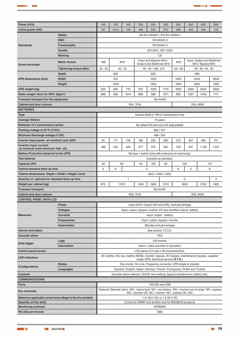
59SALICRU
Power (kVA) 100 125 160 200 250 300 400 500 600 800
Active power (kW) 90 112,5 144 180 225 270 360 450 540 720
Standards
Safety EN-IEC 62040-1, EN-IEC 60950-1
EMC EN 62040-2
Functionality EN 62040-3
Quality ISO 9001, ISO 14001
Marking CE
Screw terminalsMetric thread M8 M10 Input and Bypass M10 /
Output and Batteries M16 M12 Input, Output and Batteries M12 / Bypass M10
Tightening torque (Nm) 20.. 25 40.. 50 40.. 50 / 128.. 212 69.. 85 69.. 85 / 40.. 50
UPS dimensions (mm)
Depth 825 855 950
Width 815 1220 1990 2440 3640
Height 1670 1905 1920 2020 1920
UPS weight (kg) 625 660 715 970 1090 1170 1955 2482 2535 3600
Static weight -floor for UPS- (kg/m2) 886 936 1014 888 988 1071 992 1027 1049 1111
Foreseen transport for the equipment By forklift
Cabinet and door colours RAL 7016 RAL 9005
BATTERIES
Type Sealed AGM or VRLA maintenance free.
Average lifetime 10 years.
Batteries 12 V connected in series By default 50 and up to 52 (adjustable).
Floating voltage at 25 ºC (V DC) 680 / 707
Minimum discharge voltage (V DC) 496 / 516
Inverter input power -at nominal Load- (kW) 93 117 149 186 232 280 373 467 560 747
Inverter input current -at nominal load-minimum Vdc- (A) 188 235 300 377 470 565 753 941 1.129 1.507
Battery Protection (external to the UPS) By fuse + switch (only with extension of autonomy)
Test baterías Included as standard
Capacity (Ah) 40 65 40 100 65 100 115
Typical standard back up time 5 6 5 6 5 6
Cabinet dimensions -Depth x Width x Height- (mm) 855 x 1305 x 1905
Quantity of cabinets for standard back up time 1 2 3
Weight per cabinet (kg) 875 1370 1550 1800 1370 1800 2125 1925
Foreseen transport By forklift.
Cabinet and door colours RAL 7016 RAL 9005
CONTROL PANEL WITH LCD
Measures
Power Input (kVA), Output (kW and kVA), load percentage.
Voltages Input, output, bypass, inverter, DC bus (rectifier output), battery.
Currents Input, output, battery.
Frequencies Input, output, bypass, inverter.
Autonomies Minutes and percentage.
Alarms and status See section 7.3.3.2.
Acoustic alarm YES
Data loggerLogs 250 events.
Information Alarm + date and time of activation.
Control panel screen LCD panel of 2 rows x 30 characters/line.
LED indicators AC rectifier, DC bus, battery MCBs, inverter, bypass, AC bypass, maintenance bypass, supplied loads, EPO, technical service (S.T.S.)
ConfigurationsModes Eco-mode, On-Line, Frequency converter, UPS single or parallel.
Languages Spanish, English, Italian, German, French, Portuguese, Polish and Turkish.
Controls Acoustic alarm silencer, On/Off, time setting, bypass transference, battery test.
COMMUNICATIONS
Ports RS-232 and USB
Dry contracts Optional (General alarm -NO-, mains fault -NO-, low battery -NO-, inverter out of range -NO-, bypass -NO-, booster OK -NC-, inverter -NC-, bypass OK -NC-.
Maximum applicable current and voltage to the dry contacts 1 A 120 V AC or 1 A 50 V DC
Quantity of free slots 2 (One for SNMP and another one for MODBUS protocol).
Monitoring software UPSMAN.
RS-232 port format DB9.
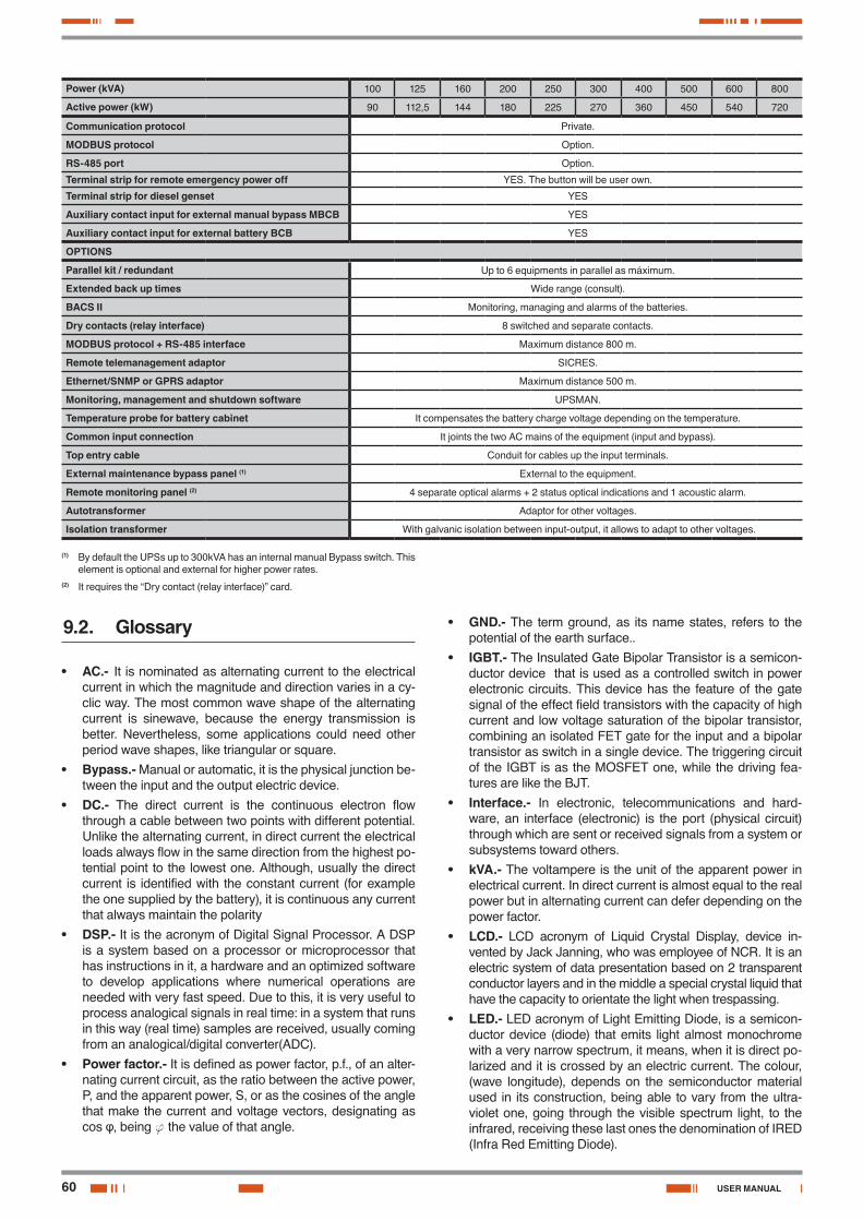
60
Power (kVA) 100 125 160 200 250 300 400 500 600 800
Active power (kW) 90 112,5 144 180 225 270 360 450 540 720
Communication protocol Private.
MODBUS protocol Option.
RS-485 port Option.
Terminal strip for remote emergency power off YES. The button will be user own.
Terminal strip for diesel genset YES
Auxiliary contact input for external manual bypass MBCB YES
Auxiliary contact input for external battery BCB YES
OPTIONS
Parallel kit / redundant Up to 6 equipments in parallel as máximum.
Extended back up times Wide range (consult).
BACS II Monitoring, managing and alarms of the batteries.
Dry contacts (relay interface) 8 switched and separate contacts.
MODBUS protocol + RS-485 interface Maximum distance 800 m.
Remote telemanagement adaptor SICRES.
Ethernet/SNMP or GPRS adaptor Maximum distance 500 m.
Monitoring, management and shutdown software UPSMAN.
Temperature probe for battery cabinet It compensates the battery charge voltage depending on the temperature.
Common input connection It joints the two AC mains of the equipment (input and bypass).
Top entry cable Conduit for cables up the input terminals.
External maintenance bypass panel (1) External to the equipment.
Remote monitoring panel (2) 4 separate optical alarms + 2 status optical indications and 1 acoustic alarm.
Autotransformer Adaptor for other voltages.
Isolation transformer With galvanic isolation between input-output, it allows to adapt to other voltages.
(1) By default the UPSs up to 300kVA has an internal manual Bypass switch. This element is optional and external for higher power rates.
(2) It requires the “Dry contact (relay interface)” card.
9.2. Glossary
• AC.- It is nominated as alternating current to the electrical current in which the magnitude and direction varies in a cy-clic way. The most common wave shape of the alternating current is sinewave, because the energy transmission is better. Nevertheless, some applications could need other period wave shapes, like triangular or square.
• Bypass.- Manual or automatic, it is the physical junction be-tween the input and the output electric device.
• DC.- The direct current is the continuous electron flow through a cable between two points with different potential. Unlike the alternating current, in direct current the electrical loads always flow in the same direction from the highest po-tential point to the lowest one. Although, usually the direct current is identified with the constant current (for example the one supplied by the battery), it is continuous any current that always maintain the polarity
• DSP.- It is the acronym of Digital Signal Processor. A DSP is a system based on a processor or microprocessor that has instructions in it, a hardware and an optimized software to develop applications where numerical operations are needed with very fast speed. Due to this, it is very useful to process analogical signals in real time: in a system that runs in this way (real time) samples are received, usually coming from an analogical/digital converter(ADC).
• Power factor.- It is defined as power factor, p.f., of an alter-nating current circuit, as the ratio between the active power, P, and the apparent power, S, or as the cosines of the angle that make the current and voltage vectors, designating as cos φ, being f the value of that angle.
• GND.- The term ground, as its name states, refers to the potential of the earth surface..
• IGBT.- The Insulated Gate Bipolar Transistor is a semicon-ductor device that is used as a controlled switch in power electronic circuits. This device has the feature of the gate signal of the effect field transistors with the capacity of high current and low voltage saturation of the bipolar transistor, combining an isolated FET gate for the input and a bipolar transistor as switch in a single device. The triggering circuit of the IGBT is as the MOSFET one, while the driving fea-tures are like the BJT.
• Interface.- In electronic, telecommunications and hard-ware, an interface (electronic) is the port (physical circuit) through which are sent or received signals from a system or subsystems toward others.
• kVA.- The voltampere is the unit of the apparent power in electrical current. In direct current is almost equal to the real power but in alternating current can defer depending on the power factor.
• LCD.- LCD acronym of Liquid Crystal Display, device in-vented by Jack Janning, who was employee of NCR. It is an electric system of data presentation based on 2 transparent conductor layers and in the middle a special crystal liquid that have the capacity to orientate the light when trespassing.
• LED.- LED acronym of Light Emitting Diode, is a semicon-ductor device (diode) that emits light almost monochrome with a very narrow spectrum, it means, when it is direct po-larized and it is crossed by an electric current. The colour, (wave longitude), depends on the semiconductor material used in its construction, being able to vary from the ultra-violet one, going through the visible spectrum light, to the infrared, receiving these last ones the denomination of IRED (Infra Red Emitting Diode).
USER MANUAL
61SALICRU
• Circuit breaker.- A circuit breaker or switch, is a device ready to break the electrical current of a circuit when it over-comes the maximum set values.
• On-Line mode- Regarding to an equipment, it is on line when it is connected to the system, and it is in operation, and usually has its power supply turned on.
• Inverter.- An inverter, is a circuit used to convert direct cur-rent into alternating current. The function of an inverter is to change an input voltage of direct current into a symmetrical output voltage of alternating current, with the required mag-nitude and frequency by the user or the designer.
• Rectifier.- In electronic, a rectifier is the element or circuit that allows to convert the alternating current into direct cur-rent. This is done by rectifier diodes, which can be solid state semiconductors, vacuum or gassy valves as the mercury vapour. Depending on the features of the alternating current power supply used, it is classified as single phase, when they are fed by a single phase electrical mains, or three phase when they are fed by the three phases. Depending on the rectification type, they can be half wave, when only one of the current semi-cycles is used, or full wave, where both semi-cycles are used.
• Relay.- The relay (in French relais, relief) is an electrome-chanical device that works as a switch controlled by an electric circuit where, through an electromagnet, a set of contacts are moved and it allows to open or to close other independent electric circuits..

62
: ..................................................................................................................................................................................................................
................................................................................................................................................................................................................................
................................................................................................................................................................................................................................
................................................................................................................................................................................................................................
................................................................................................................................................................................................................................
................................................................................................................................................................................................................................
................................................................................................................................................................................................................................
................................................................................................................................................................................................................................
................................................................................................................................................................................................................................
................................................................................................................................................................................................................................
................................................................................................................................................................................................................................
................................................................................................................................................................................................................................
................................................................................................................................................................................................................................
................................................................................................................................................................................................................................
................................................................................................................................................................................................................................
................................................................................................................................................................................................................................
................................................................................................................................................................................................................................
................................................................................................................................................................................................................................
................................................................................................................................................................................................................................
................................................................................................................................................................................................................................
................................................................................................................................................................................................................................
................................................................................................................................................................................................................................
................................................................................................................................................................................................................................
................................................................................................................................................................................................................................
................................................................................................................................................................................................................................
................................................................................................................................................................................................................................
USER MANUAL

63SALICRU
: ..................................................................................................................................................................................................................
................................................................................................................................................................................................................................
................................................................................................................................................................................................................................
................................................................................................................................................................................................................................
................................................................................................................................................................................................................................
................................................................................................................................................................................................................................
................................................................................................................................................................................................................................
................................................................................................................................................................................................................................
................................................................................................................................................................................................................................
................................................................................................................................................................................................................................
................................................................................................................................................................................................................................
................................................................................................................................................................................................................................
................................................................................................................................................................................................................................
................................................................................................................................................................................................................................
................................................................................................................................................................................................................................
................................................................................................................................................................................................................................
................................................................................................................................................................................................................................
................................................................................................................................................................................................................................
................................................................................................................................................................................................................................
................................................................................................................................................................................................................................
................................................................................................................................................................................................................................
................................................................................................................................................................................................................................
................................................................................................................................................................................................................................
................................................................................................................................................................................................................................
................................................................................................................................................................................................................................
................................................................................................................................................................................................................................
Avda. de la Serra 100
08460 Palautordera
BARCELONA
Tel. +34 93 848 24 00
Fax +34 93 848 22 05
SALICRU.COM
www.linkedin.com/company/salicru
@salicru_SA
Product Range
Uninterruptible Power Supplies (UPS)
Lighting Flow Dimmer-Stabilisers
DC Power Systems
Static Inverters
Photovoltaic Inverters
Voltage stabilisers
Variable frequency drives
The Technical Service and Support (T.S.S.) network,
Commercial network and warranty information are
available in website:
www.salicru.com
REF. EK942G01 REV. G CODE 401*


![TEST REPORT EN 62040-1 Uninterruptible power systems … · EN 62040-1 Uninterruptible power systems (UPS) ... detachable power supply cord [] non-detachable power supply cord](https://img.pdfslide.net/doc/110x75/5ca3e4f788c993ad338b7b7b/test-report-en-62040-1-uninterruptible-power-systems-en-62040-1-uninterruptible.jpg)