Embed Size (px)
Citation preview
UNIProbe - TwinProbe
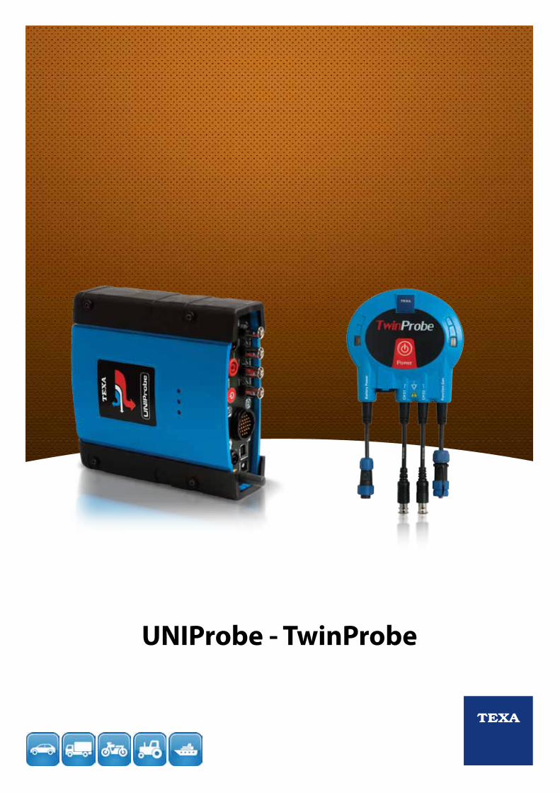
UNIProbe and TwinProbe analogue and digital measurement acquisition systems represent the best and most complete solutions for conventional diagnostic testing.They allow a complete multi-brand diagnosis, and are equally effective on bikes, scooters, quads, boats and jet skis, in addition to light and heavy commercial vehicles, buses and coaches, special vehicles and agricultural vehicles.
OSCILLOSCOPE with four independent analogue channels, complete with SIV function for interpreting the measure signal (with IDC4 software).
MULTIMETER for voltage, resistance and current measurements.
BATTERY PROBE for testing the battery, and analysing and checking the entire starting and charging system.
PRESSURE TESTER for checking fuel and turbocompressor pressure on all vehicles.
SIGNAL GENERATOR to simulate the pulses generated by sensors and reproduce the comman-ds generated by control units.
TNET for electrical testing and analysis of automotive communication networks (CAN, VAN. LIN).
UNIProbe is the most complete and performing solutions comprising 6 different instruments inside the same device:
TwO PROfESSIONAL SOLUTIONS fOR dIAGNOSIS ANd MEASURING
OSCILLOSCOPE Two independent analogue channels, with an input range of up to ± 200V, equipped with SIV function for the correct interpretation of the signal plots.
SIGNAL GENERATOR to simulate the pulses generated by sensors and reproduce the comman-ds generated by control units.
TwinProbe is the economic device. It is very handy thanks to wireless connectivity, and it’s as professional as UNIProbe, including an oscilloscope, a signal generator, a voltmeter and amperometer.
AMPEROMETERThis function can be accomplished through oscilloscope function in combination with BICOR clamp.
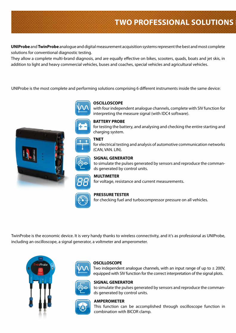
UNIProbe and TwinProbe can dialogue with all TEXA display units and with Windows PC, without the need for cables, thanks to Bluetooth wireless technology. You can, therefore, move freely around the vehicle and within the workshop. The built-in 7.4V lithium battery ensures en exceptional autonomy under continuous use. This solution follows TEXA philosophy about “two-units diagnosis” that aims at the complete deletion of cables from the workshop.
TwO PROfESSIONAL SOLUTIONS fOR dIAGNOSIS ANd MEASURING
STANdARd PC
MULTI PEGASO
AXONE RANGE
OPERATIVE SOfTwARE IdC4 ANd MSSUNIProbe and TwinProbe, like all TEXA instruments, use the operative environment IDC4, thediagnosis and self-diagnosis software with built-in databank and exceptional coverage ofmakes and models. IDC4 is available both in a standard version for PC, MULTI PEGASO and AXONE 4, as well as in a POCKET version for portable viewing units of the AXONE line, but the software potential is the same in all. The wireless Bluetooth connection or connection via USB cable, allows for the transfer of data from the instrument to the viewing unit.
SIV fUNCTIONThe oscilloscope test carried out with UNIProbe and TwinProbe guarantees excellent detection of values and a precise identification of the measurement; but what the mechanic most needs is an efficient system to help him correctly identify the graphs processed by the instrument.In order to declare if the signal analysed is correct or not, it is, however, necessary to have reference data, values that clearly show which are the critical points to be analysed.
OPERATIVE SOfTwARE
For those not having and not wishing to acquire the complete operative platform IDC4, MSS (Measurement System Software) is available, specific for UNIProbe and TwinProbe, which enables only the functions of oscilloscope, battery probe, TNET, multi-meter, pressure test and signal generator in manual mode.
This is why TEXA has developed a support that guides the mechanic throughout the test. The function developed is a software algorithm named S.I.V. (Signal Information Viewing).Thanks to this system, UNIProbe and TwinProbe do not simply view the signal; as they take the measurements and acquire the data, they process all information, analyse it and supply an assessment in real time.They are, in fact, able to process the signals of the various sensors or actuators concerned by the measurement and compare the data acquired with that present in the internal database, thereby immediately showing any signal anomalies.This mode can be used simply and quickly, starting from the wiring diagram of the system to be analysed or the list of components.By selecting the device to be verified, we automatically activate the oscilloscope, which is already configured to correctly test the component.
To check out the extensive coverage of TEXA products visit www.texa.com/applicationlist
To view demos showing TEXA instruments in operation visit www.texa.com/demo
For information on IDC4 compatibility and minimum system requirements go to
www.texa.com/system
ALL TEXA PROdUCTS ARE GUARANTEEd
fOR 24 MONThS
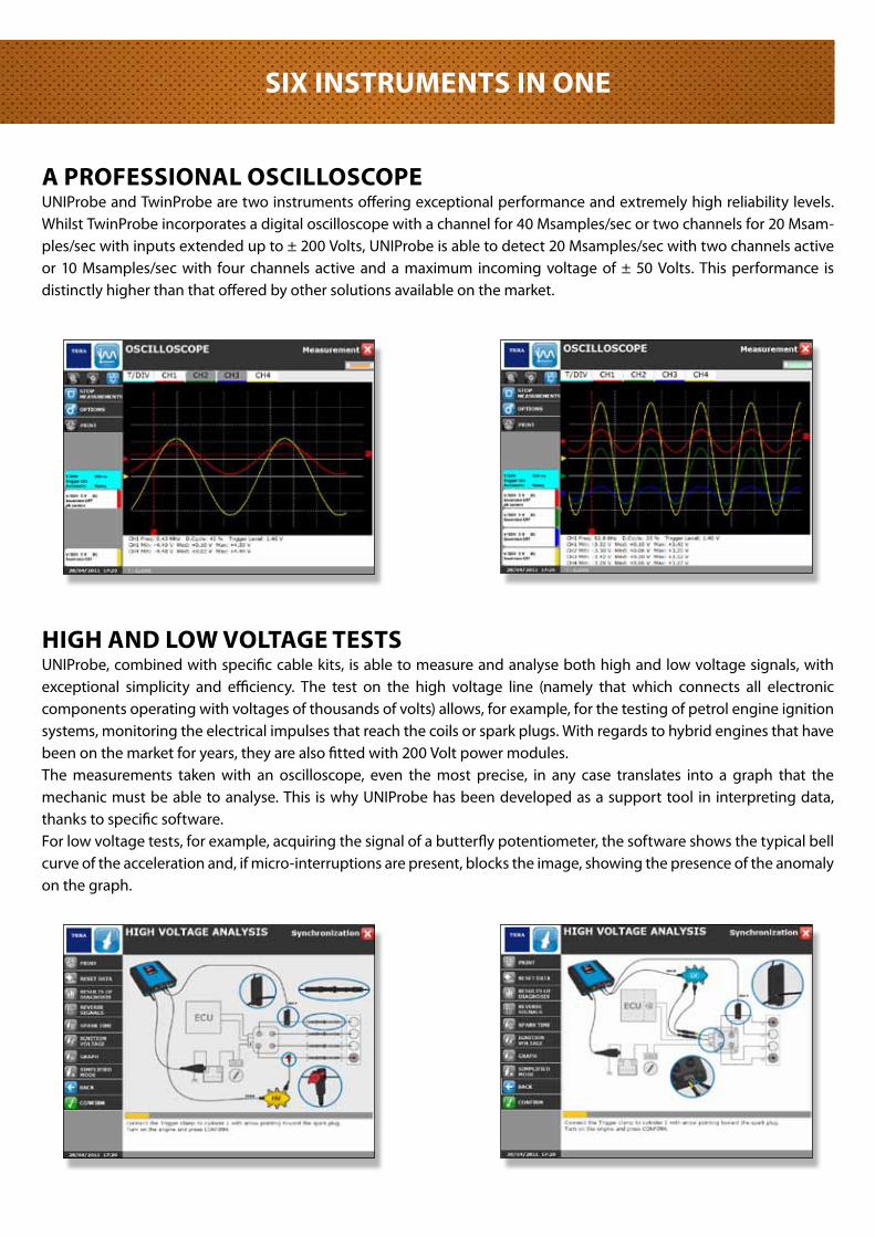
A PROfESSIONAL OSCILLOSCOPEUNIProbe and TwinProbe are two instruments offering exceptional performance and extremely high reliability levels. Whilst TwinProbe incorporates a digital oscilloscope with a channel for 40 Msamples/sec or two channels for 20 Msam-ples/sec with inputs extended up to ± 200 Volts, UNIProbe is able to detect 20 Msamples/sec with two channels active or 10 Msamples/sec with four channels active and a maximum incoming voltage of ± 50 Volts. This performance is distinctly higher than that offered by other solutions available on the market.
hIGh ANd LOw VOLTAGE TESTSUNIProbe, combined with specific cable kits, is able to measure and analyse both high and low voltage signals, with exceptional simplicity and efficiency. The test on the high voltage line (namely that which connects all electronic components operating with voltages of thousands of volts) allows, for example, for the testing of petrol engine ignition systems, monitoring the electrical impulses that reach the coils or spark plugs. With regards to hybrid engines that have been on the market for years, they are also fitted with 200 Volt power modules.The measurements taken with an oscilloscope, even the most precise, in any case translates into a graph that the mechanic must be able to analyse. This is why UNIProbe has been developed as a support tool in interpreting data, thanks to specific software.For low voltage tests, for example, acquiring the signal of a butterfly potentiometer, the software shows the typical bell curve of the acceleration and, if micro-interruptions are present, blocks the image, showing the presence of the anomaly on the graph.
SIX INSTRUMENTS IN ONE
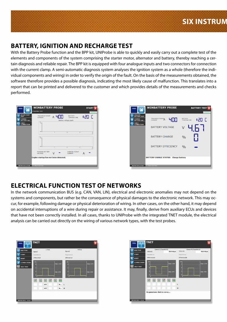
BATTERY, IGNITION ANd REChARGE TESTWith the Battery Probe function and the BPP kit, UNIProbe is able to quickly and easily carry out a complete test of the elements and components of the system comprising the starter motor, alternator and battery, thereby reaching a cer-tain diagnosis and reliable repair. The BPP kit is equipped with four analogue inputs and two connectors for connection with the current clamp. A semi-automatic diagnosis system analyses the ignition system as a whole (therefore the indi-vidual components and wiring) in order to verify the origin of the fault. On the basis of the measurements obtained, the software therefore provides a possible diagnosis, indicating the most likely cause of malfunction. This translates into a report that can be printed and delivered to the customer and which provides details of the measurements and checks performed.
ELECTRICAL fUNCTION TEST Of NETwORKSIn the network communication BUS (e.g. CAN, VAN, LIN), electrical and electronic anomalies may not depend on the systems and components, but rather be the consequence of physical damages to the electronic network. This may oc-cur, for example, following damage or physical deterioration of wiring. In other cases, on the other hand, it may depend on accidental interruptions of a wire during repair or assistance. It may, finally, derive from auxiliary ECUs and devices that have not been correctly installed. In all cases, thanks to UNIProbe with the integrated TNET module, the electrical analysis can be carried out directly on the wiring of various network types, with the test probes.
SIX INSTRUMENTS IN ONE
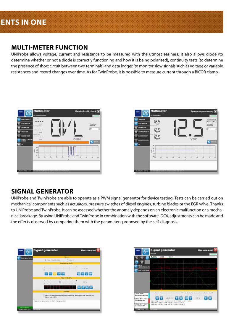
MULTI-METER fUNCTIONUNIProbe allows voltage, current and resistance to be measured with the utmost easiness; it also allows diode (to determine whether or not a diode is correctly functioning and how it is being polarised), continuity tests (to determine the presence of short circuit between two terminals) and data logger (to monitor slow signals such as voltage or variable resistances and record changes over time. As for TwinProbe, it is possible to measure current through a BICOR clamp.
SIGNAL GENERATORUNIProbe and TwinProbe are able to operate as a PWM signal generator for device testing. Tests can be carried out on mechanical components such as actuators, pressure switches of diesel engines, turbine blades or the EGR valve. Thanks to UNIProbe and TwinProbe, it can be assessed whether the anomaly depends on an electronic malfunction or a mecha-nical breakage. By using UNIProbe and TwinProbe in combination with the software IDC4, adjustments can be made and the effects observed by comparing them with the parameters proposed by the self-diagnosis.
SIX INSTRUMENTS IN ONE
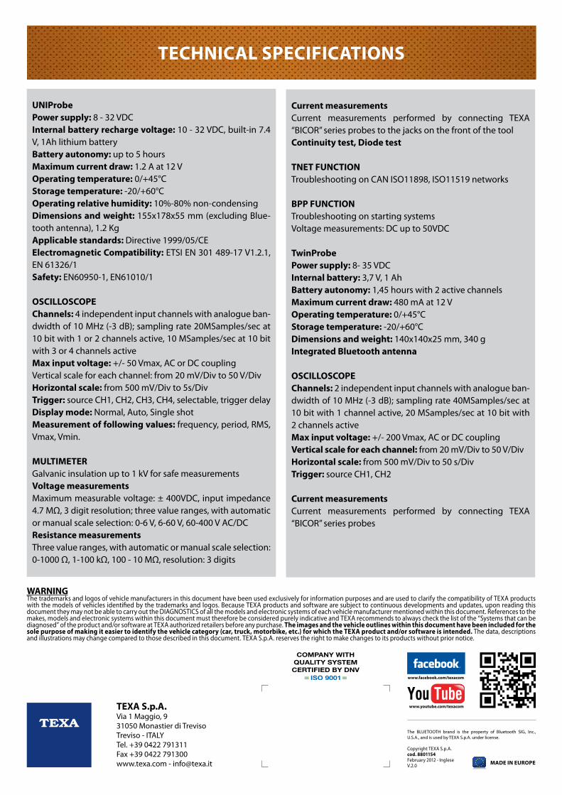
UNIProbePower supply: 8 - 32 VDCInternal battery recharge voltage: 10 - 32 VDC, built-in 7.4 V, 1Ah lithium batteryBattery autonomy: up to 5 hoursMaximum current draw: 1.2 A at 12 VOperating temperature: 0/+45°CStorage temperature: -20/+60°COperating relative humidity: 10%-80% non-condensingdimensions and weight: 155x178x55 mm (excluding Blue-tooth antenna), 1.2 KgApplicable standards: Directive 1999/05/CEElectromagnetic Compatibility: ETSI EN 301 489-17 V1.2.1, EN 61326/1Safety: EN60950-1, EN61010/1
OSCILLOSCOPEChannels: 4 independent input channels with analogue ban-dwidth of 10 MHz (-3 dB); sampling rate 20MSamples/sec at 10 bit with 1 or 2 channels active, 10 MSamples/sec at 10 bit with 3 or 4 channels activeMax input voltage: +/- 50 Vmax, AC or DC couplingVertical scale for each channel: from 20 mV/Div to 50 V/Divhorizontal scale: from 500 mV/Div to 5s/DivTrigger: source CH1, CH2, CH3, CH4, selectable, trigger delaydisplay mode: Normal, Auto, Single shotMeasurement of following values: frequency, period, RMS, Vmax, Vmin.
MULTIMETERGalvanic insulation up to 1 kV for safe measurementsVoltage measurementsMaximum measurable voltage: ± 400VDC, input impedance 4.7 MΩ, 3 digit resolution; three value ranges, with automatic or manual scale selection: 0-6 V, 6-60 V, 60-400 V AC/DCResistance measurementsThree value ranges, with automatic or manual scale selection: 0-1000 Ω, 1-100 kΩ, 100 - 10 MΩ, resolution: 3 digits
Current measurementsCurrent measurements performed by connecting TEXA “BICOR” series probes to the jacks on the front of the tool Continuity test, diode test
TNET fUNCTIONTroubleshooting on CAN ISO11898, ISO11519 networks
BPP fUNCTIONTroubleshooting on starting systemsVoltage measurements: DC up to 50VDC
TwinProbePower supply: 8- 35 VDCInternal battery: 3,7 V, 1 AhBattery autonomy: 1,45 hours with 2 active channelsMaximum current draw: 480 mA at 12 VOperating temperature: 0/+45°CStorage temperature: -20/+60°Cdimensions and weight: 140x140x25 mm, 340 gIntegrated Bluetooth antenna
OSCILLOSCOPEChannels: 2 independent input channels with analogue ban-dwidth of 10 MHz (-3 dB); sampling rate 40MSamples/sec at 10 bit with 1 channel active, 20 MSamples/sec at 10 bit with 2 channels activeMax input voltage: +/- 200 Vmax, AC or DC couplingVertical scale for each channel: from 20 mV/Div to 50 V/Divhorizontal scale: from 500 mV/Div to 50 s/DivTrigger: source CH1, CH2
Current measurementsCurrent measurements performed by connecting TEXA “BICOR” series probes
TEChNICAL SPECIfICATIONS
MAdE IN EUROPE
TEXA S.p.A.Via 1 Maggio, 931050 Monastier di TrevisoTreviso - ITALYTel. +39 0422 791311Fax +39 0422 791300www.texa.com - [email protected]
The BLUETOOTH brand is the property of Bluetooth SIG, Inc., U.S.A., and is used by TEXA S.p.A. under license.
Copyright TEXA S.p.A.cod. 8801154February 2012 - IngleseV.2.0
www.facebook.com/texacom
www.youtube.com/texacom
wARNINGThe trademarks and logos of vehicle manufacturers in this document have been used exclusively for information purposes and are used to clarify the compatibility of TEXA products with the models of vehicles identified by the trademarks and logos. Because TEXA products and software are subject to continuous developments and updates, upon reading this document they may not be able to carry out the DIAGNOSTICS of all the models and electronic systems of each vehicle manufacturer mentioned within this document. References to the makes, models and electronic systems within this document must therefore be considered purely indicative and TEXA recommends to always check the list of the “Systems that can be diagnosed” of the product and/or software at TEXA authorized retailers before any purchase. The images and the vehicle outlines within this document have been included for the sole purpose of making it easier to identify the vehicle category (car, truck, motorbike, etc.) for which the TEXA product and/or software is intended. The data, descriptions and illustrations may change compared to those described in this document. TEXA S.p.A. reserves the right to make changes to its products without prior notice.