Embed Size (px)
Citation preview
UniS
CS297 Graphics with Java and OpenGL
Viewing, the model view matrix
2
UniS
coordinates to pixel positions
• A series computer operations convert an object's three-dimensional coordinates to pixel positions on the screen.
• Transformations, which are represented by matrix multiplication, include – modeling, – viewing, – projection operations.
• Such operations include – rotation, – translation, – scaling, – reflecting, – orthographic projection, – and perspective projection.
3
UniS
coordinates to pixel positions
• Generally, you use a combination of several transformations to draw a scene.
• Since the scene is rendered on a rectangular window, objects (or parts of objects) that lie outside the window must be clipped.
• In three-dimensional computer graphics, clipping occurs by throwing out objects on one side of a clipping plane.
• Finally, a correspondence must be established between the transformed coordinates and screen pixels.
• This is known as a viewport transformation.
4
UniS
Overview: The Camera Analogy
• Set up your tripod and pointing the camera at the scene (viewing transformation).
• Arrange the scene to be photographed into the desired composition (modeling transformation).
• Choose a camera lens or adjust the zoom (projection transformation).
• Determine how large you want the final photograph to be - for example, you might want it enlarged (viewport transformation).
• After these steps are performed, the picture can be snapped or the scene can be drawn.
5
UniS
Overview: The Camera Analogy
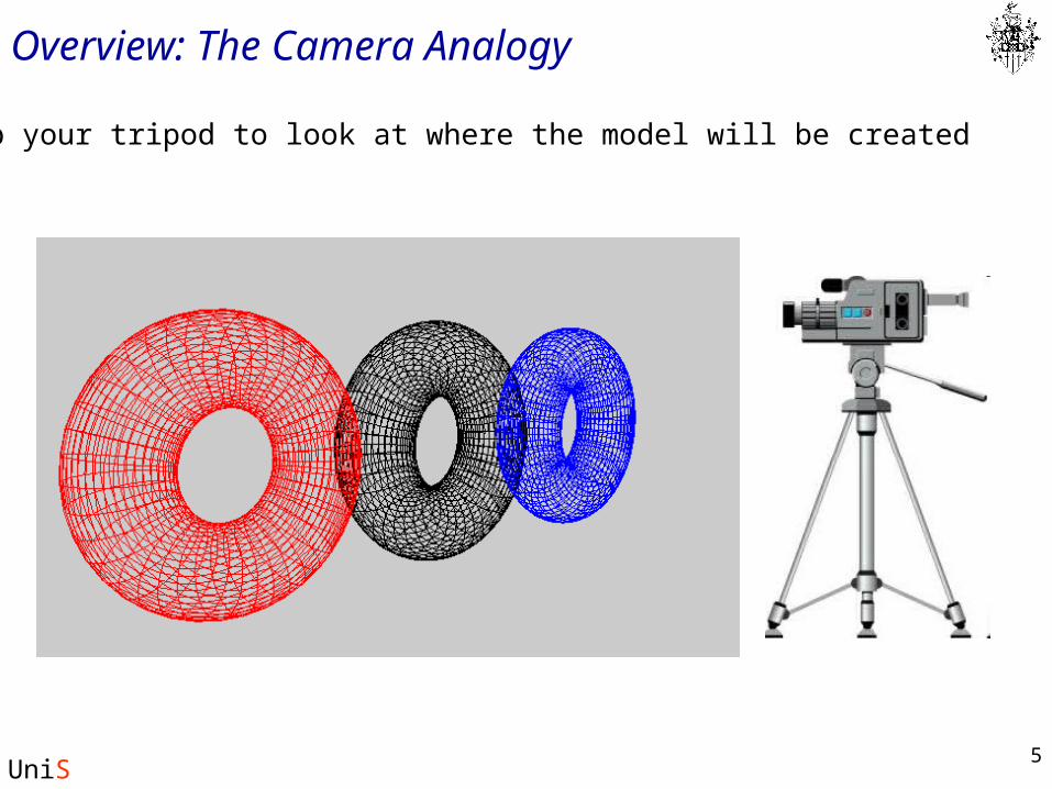
Set up your tripod to look at where the model will be created
6
UniS
Overview: The Camera Analogy
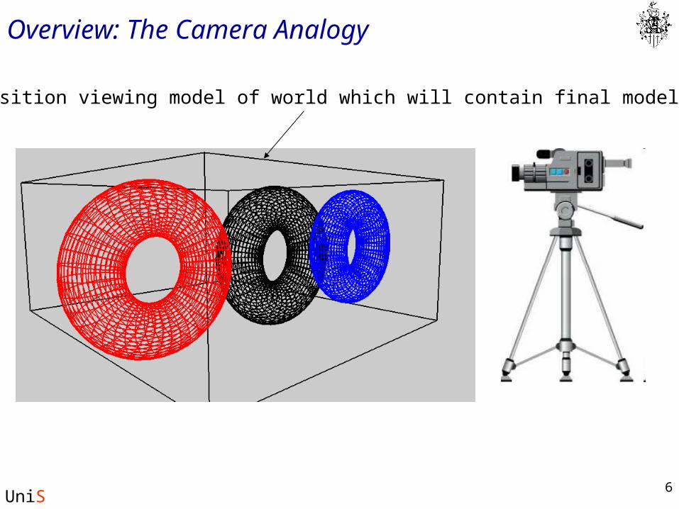
Position viewing model of world which will contain final model
7
UniS
Overview: The Camera Analogy
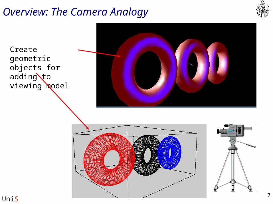
Create geometric objects for adding to viewing model
8
UniS
Overview: The Camera Analogy
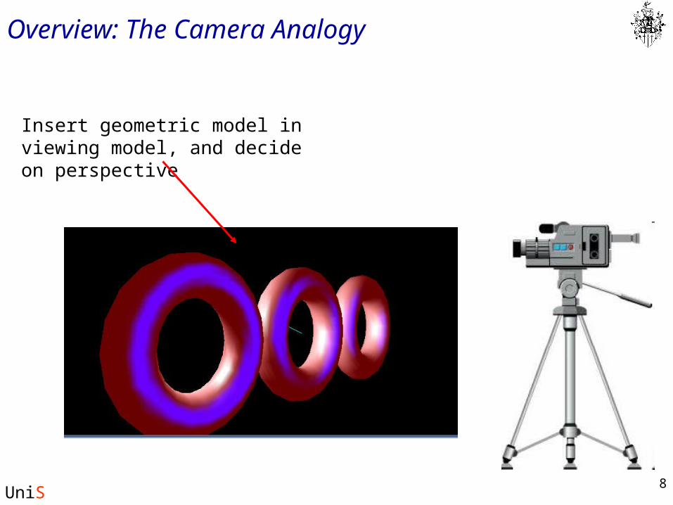
Insert geometric model in viewing model, and decide on perspective
9
UniS
Perspective choices
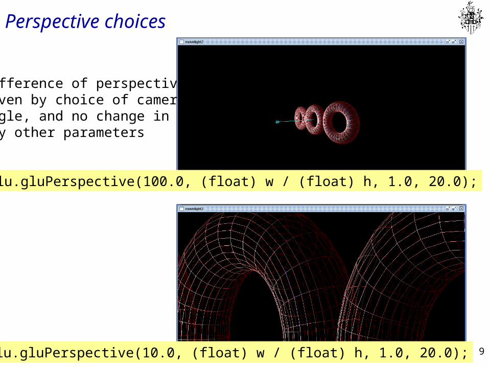
glu.gluPerspective(10.0, (float) w / (float) h, 1.0, 20.0);
glu.gluPerspective(100.0, (float) w / (float) h, 1.0, 20.0);
Difference of perspectivegiven by choice of cameraangle, and no change in any other parameters
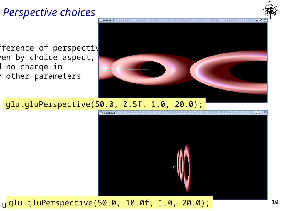
10
UniS
Perspective choices
glu.gluPerspective(50.0, 10.0f, 1.0, 20.0);
Difference of perspectivegiven by choice aspect,and no change in any other parameters
glu.gluPerspective(50.0, 0.5f, 1.0, 20.0);
11
UniS
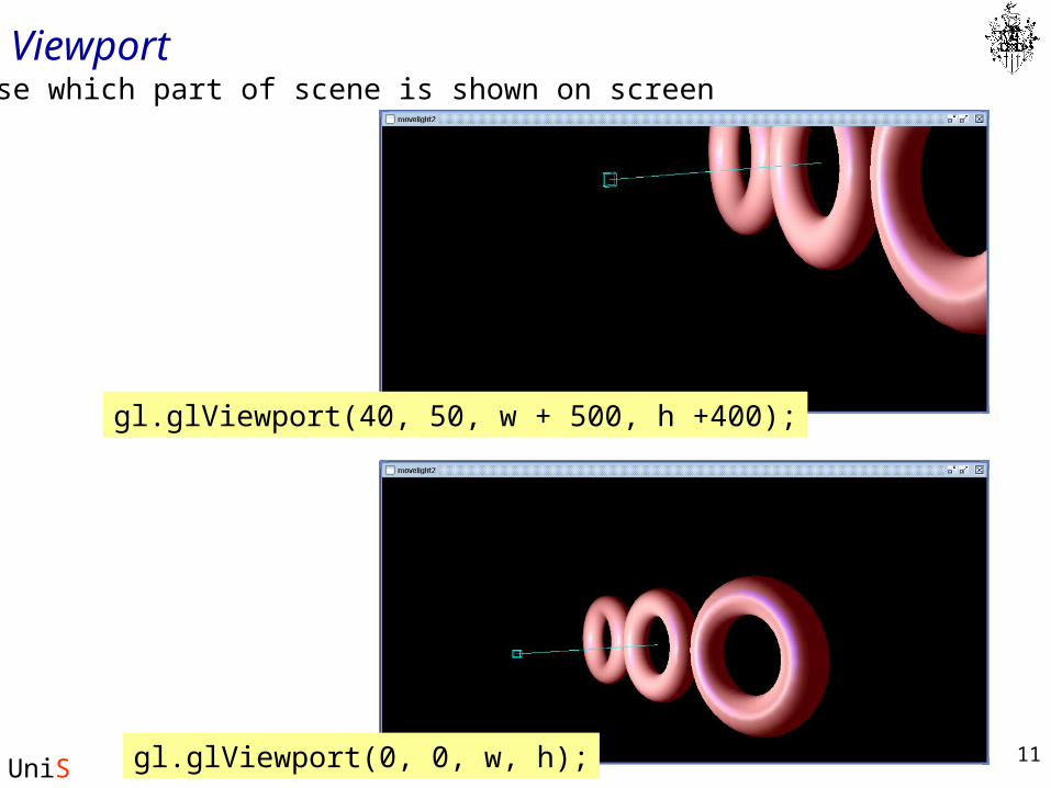
ViewportChoose which part of scene is shown on screen
gl.glViewport(40, 50, w + 500, h +400);
gl.glViewport(0, 0, w, h);
12
UniS
Computer Vertex Transformations Pipeline
• Note that these steps correspond to the order in which you specify the desired transformations in your program, not necessarily the order in which the relevant mathematical operations are performed on an object's vertices.
• The viewing transformations must precede the modeling transformations in your code.
• You can specify the projection and viewport transformations at any point before drawing occurs.
13
UniS
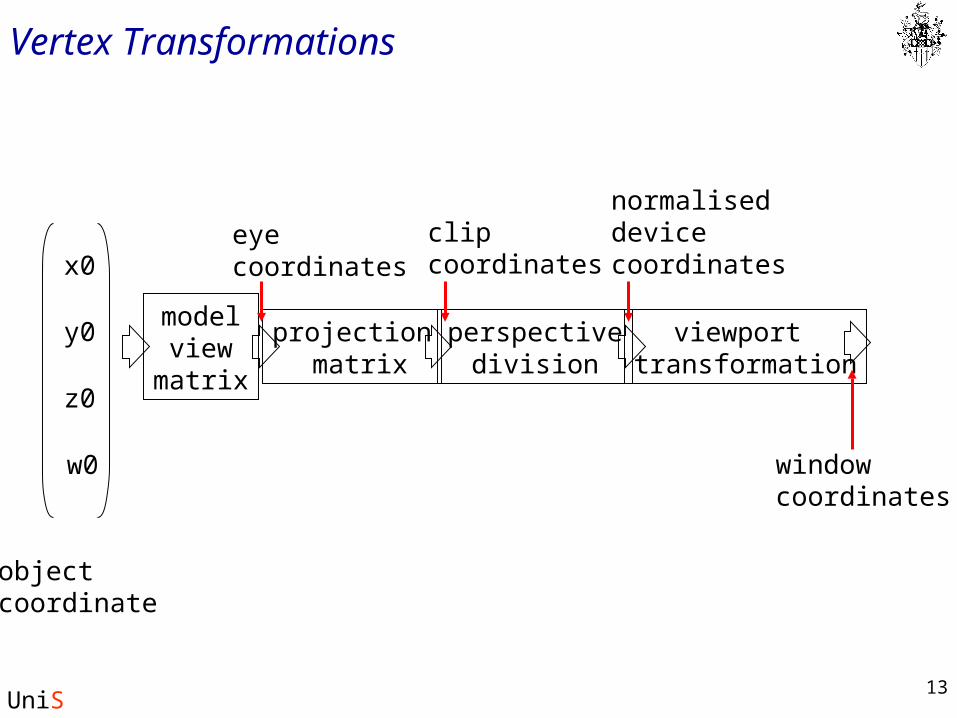
Vertex Transformations
x0
y0
z0
w0
objectcoordinate
modelview
matrix
projection matrix
perspectivedivision
viewport transformation
eyecoordinates
clipcoordinates
normalised devicecoordinates
windowcoordinates
14
UniS
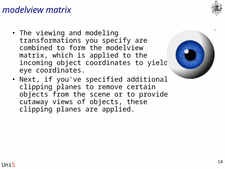
modelview matrix
• The viewing and modeling transformations you specify are combined to form the modelview matrix, which is applied to the incoming object coordinates to yield eye coordinates.
• Next, if you've specified additional clipping planes to remove certain objects from the scene or to provide cutaway views of objects, these clipping planes are applied.
15
UniS
clip coordinates
• After that, OpenGL applies the projection matrix to yield clip coordinates.
• This transformation defines a viewing volume; objects outside this volume are clipped so that they're not drawn in the final scene.
• After this point, the perspective division is performed by dividing coordinate values by w (the forth coordinate in a vertex), to produce normalized device coordinates. (See Appendix F of the Redbook for more information.)
• Finally, the transformed coordinates are converted to window coordinates by applying the viewport transformation.
• You can manipulate the dimensions of the viewport to cause the final image to be enlarged, shrunk, or stretched.
16
UniS
Matrix transformations
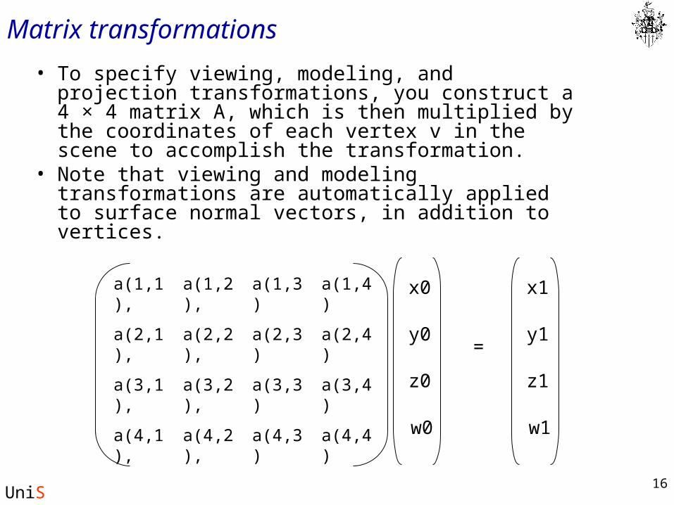
• To specify viewing, modeling, and projection transformations, you construct a 4 × 4 matrix A, which is then multiplied by the coordinates of each vertex v in the scene to accomplish the transformation.
• Note that viewing and modeling transformations are automatically applied to surface normal vectors, in addition to vertices.
a(3,4)a(3,3)a(3,2),a(3,1),
a(4,3)
a(2,3)
a(1,3)
a(4,4)a(4,2),a(4,1),
a(2,4)a(2,2),a(2,1),
a(1,4)a(1,2),a(1,1), x0
y0
z0
w0
x1
y1
z1
w1
=
17
UniS
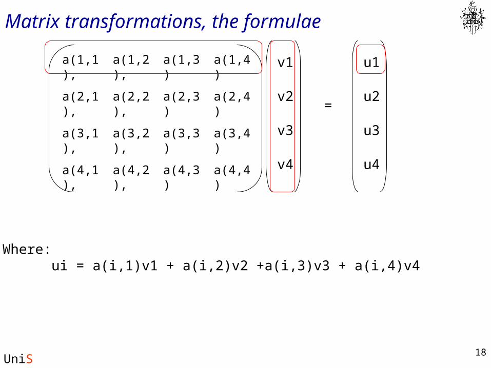
Matrix transformations, the formulae
a(3,4)a(3,3)a(3,2),a(3,1),
a(4,3)
a(2,3)
a(1,3)
a(4,4)a(4,2),a(4,1),
a(2,4)a(2,2),a(2,1),
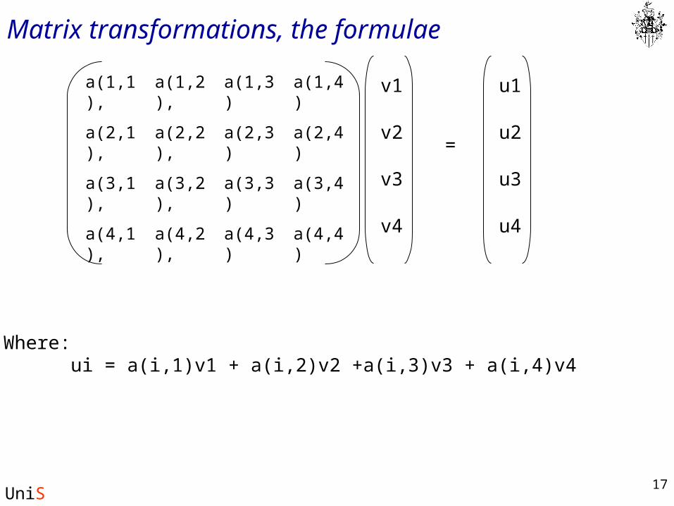
a(1,4)a(1,2),a(1,1), v1
v2
v3
v4
u1
u2
u3
u4
=
Where:ui = a(i,1)v1 + a(i,2)v2 +a(i,3)v3 + a(i,4)v4
18
UniS
Matrix transformations, the formulae
a(3,4)a(3,3)a(3,2),a(3,1),
a(4,3)
a(2,3)
a(1,3)
a(4,4)a(4,2),a(4,1),
a(2,4)a(2,2),a(2,1),
a(1,4)a(1,2),a(1,1), v1
v2
v3
v4
u1
u2
u3
u4
=
Where:ui = a(i,1)v1 + a(i,2)v2 +a(i,3)v3 + a(i,4)v4
19
UniS
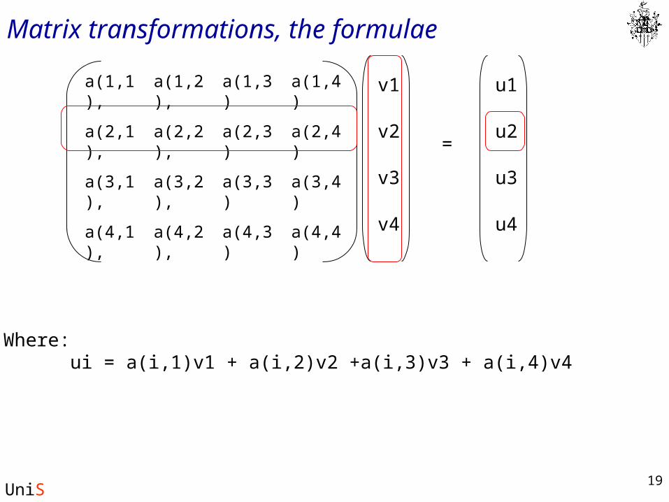
Matrix transformations, the formulae
a(3,4)a(3,3)a(3,2),a(3,1),
a(4,3)
a(2,3)
a(1,3)
a(4,4)a(4,2),a(4,1),
a(2,4)a(2,2),a(2,1),
a(1,4)a(1,2),a(1,1), v1
v2
v3
v4
u1
u2
u3
u4
=
Where:ui = a(i,1)v1 + a(i,2)v2 +a(i,3)v3 + a(i,4)v4
20
UniS
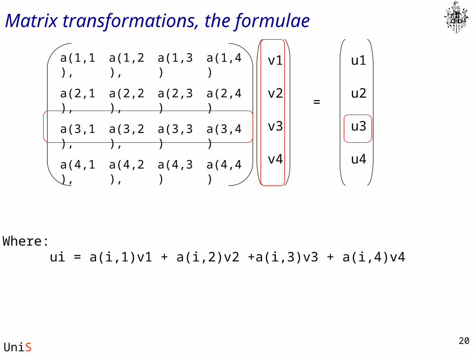
Matrix transformations, the formulae
a(3,4)a(3,3)a(3,2),a(3,1),
a(4,3)
a(2,3)
a(1,3)
a(4,4)a(4,2),a(4,1),
a(2,4)a(2,2),a(2,1),
a(1,4)a(1,2),a(1,1), v1
v2
v3
v4
u1
u2
u3
u4
=
Where:ui = a(i,1)v1 + a(i,2)v2 +a(i,3)v3 + a(i,4)v4
21
UniS
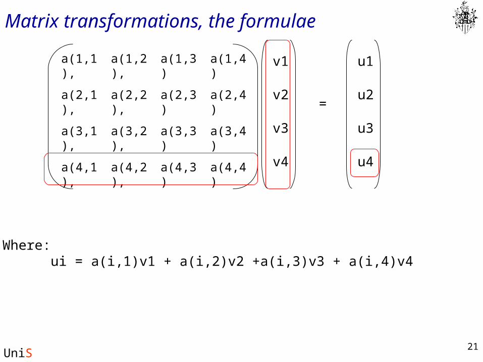
Matrix transformations, the formulae
a(3,4)a(3,3)a(3,2),a(3,1),
a(4,3)
a(2,3)
a(1,3)
a(4,4)a(4,2),a(4,1),
a(2,4)a(2,2),a(2,1),
a(1,4)a(1,2),a(1,1), v1
v2
v3
v4
u1
u2
u3
u4
=
Where:ui = a(i,1)v1 + a(i,2)v2 +a(i,3)v3 + a(i,4)v4
22
UniS
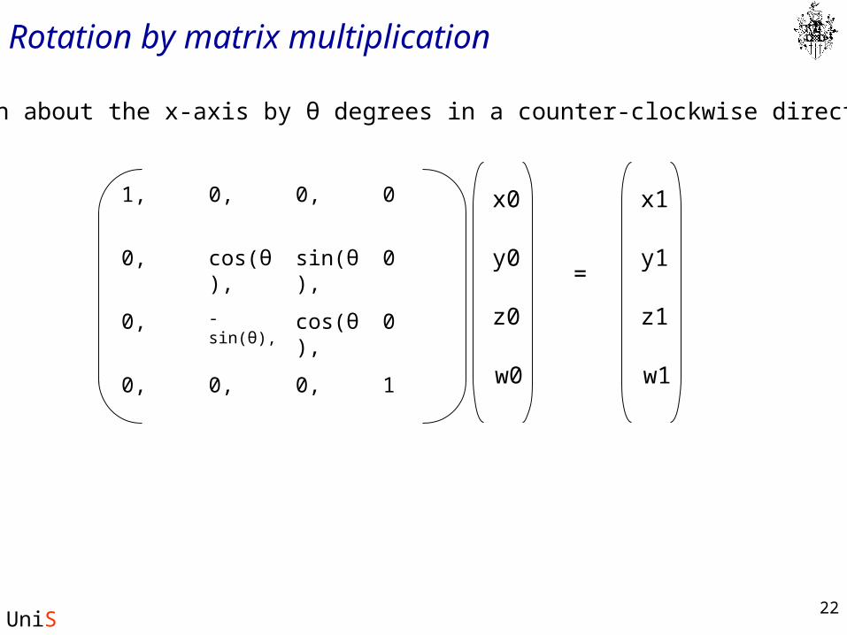
Rotation by matrix multiplication
0cos(θ),-sin(θ),0,
0,
sin(θ),
0,
10,0,
0cos(θ),0,
00,1, x0
y0
z0
w0
x1
y1
z1
w1
=
Rotation about the x-axis by θ degrees in a counter-clockwise direction
23
UniS
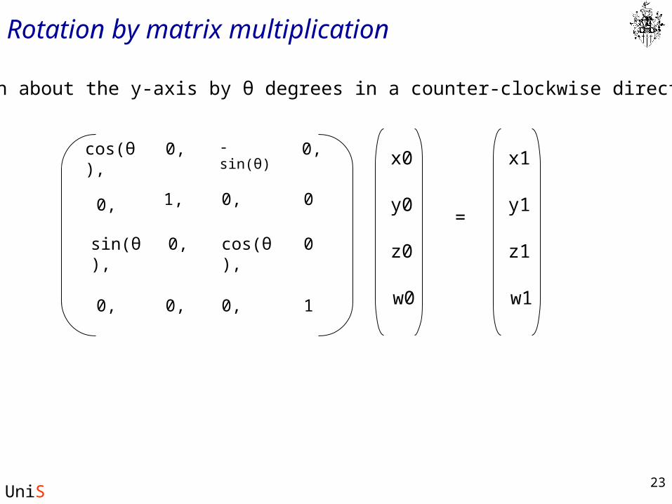
Rotation by matrix multiplication
0cos(θ),
-sin(θ)
0,
0,
sin(θ),
0,
10,0,
0
cos(θ),
0,
0,
0,
1,
x0
y0
z0
w0
x1
y1
z1
w1
=
Rotation about the y-axis by θ degrees in a counter-clockwise direction
24
UniS
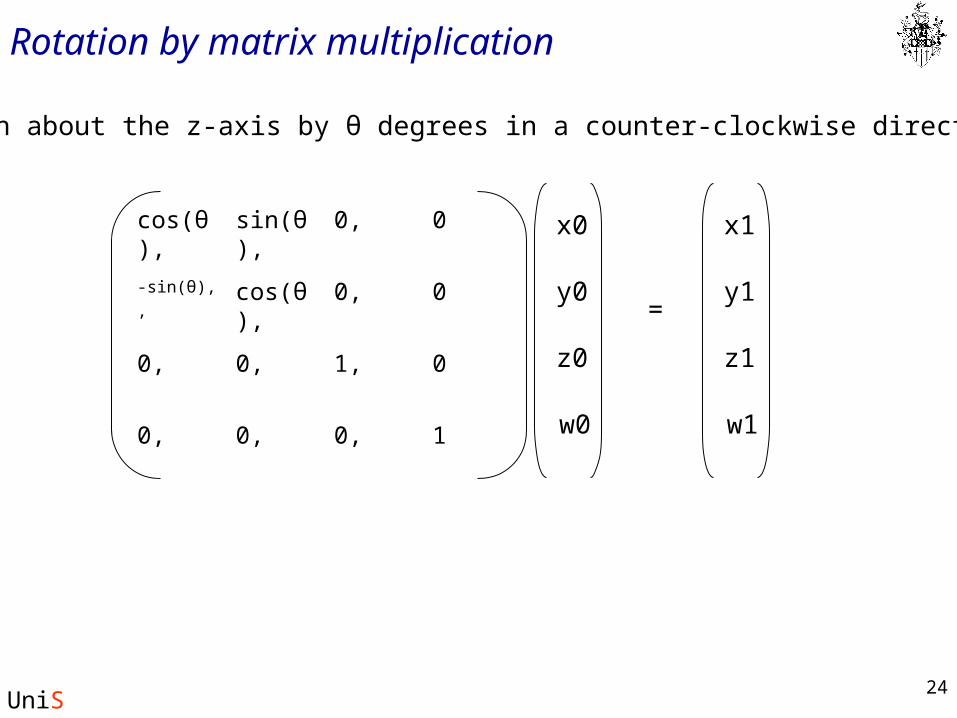
Rotation by matrix multiplication
Rotation about the z-axis by θ degrees in a counter-clockwise direction
01,0,0,
0,
0,
0,
10,0,
0cos(θ),-sin(θ),
,
0sin(θ),cos(θ), x0
y0
z0
w0
x1
y1
z1
w1
=
25
UniS
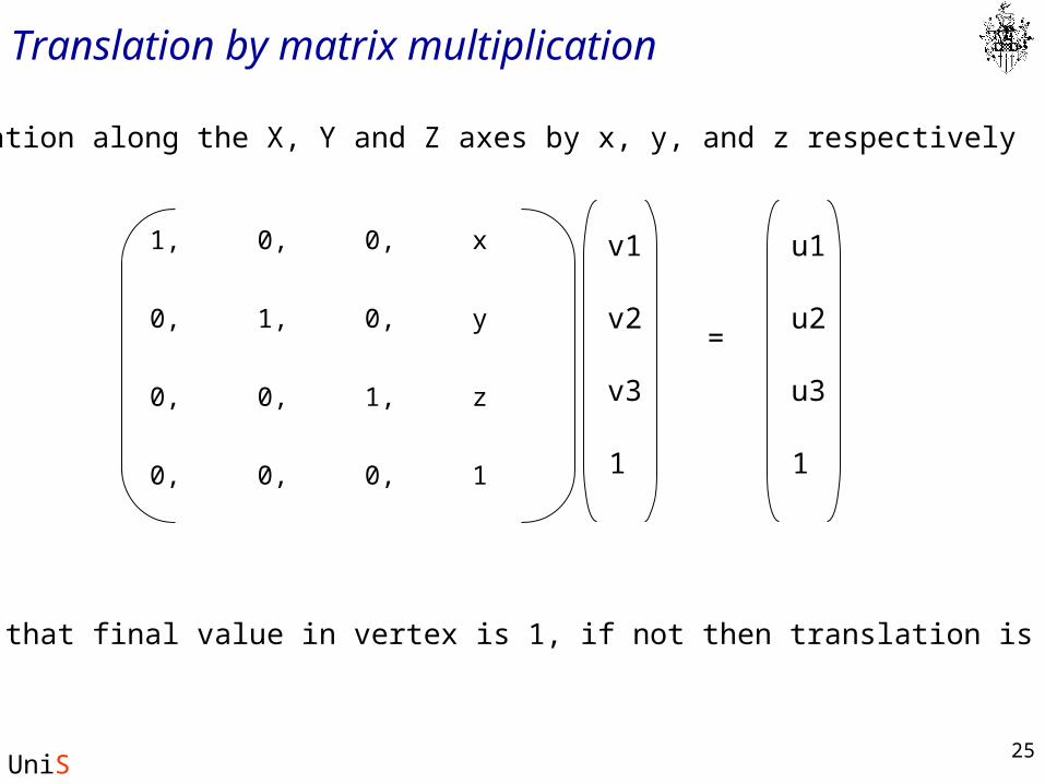
Translation by matrix multiplication
Translation along the X, Y and Z axes by x, y, and z respectively
z1,0,0,
0,
0,
0,
10,0,
y1,0,
x0,1, v1
v2
v3
1
u1
u2
u3
1
=
ASSUMES that final value in vertex is 1, if not then translation is scaled.
26
UniS
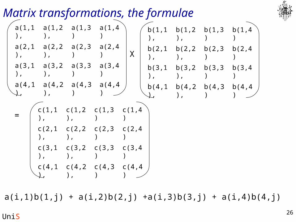
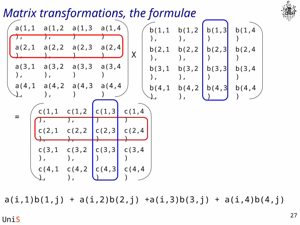
Matrix transformations, the formulae
c(i,j) = a(i,1)b(1,j) + a(i,2)b(2,j) +a(i,3)b(3,j) + a(i,4)b(4,j)
a(3,4)a(3,3)a(3,2),a(3,1),
a(4,3)
a(2,3)
a(1,3)
a(4,4)a(4,2),a(4,1),
a(2,4)a(2,2),a(2,1),
a(1,4)a(1,2),a(1,1),
b(3,4)b(3,3)b(3,2),b(3,1),
b(4,3)
b(2,3)
b(1,3)
b(4,4)b(4,2),b(4,1),
b(2,4)b(2,2),b(2,1),
b(1,4)b(1,2),b(1,1),
X
=
c(3,4)c(3,3)c(3,2),c(3,1),
c(4,3)
c(2,3)
c(1,3)
c(4,4)c(4,2),c(4,1),
c(2,4)c(2,2),c(2,1),
c(1,4)c(1,2),c(1,1),
27
UniS
Matrix transformations, the formulae
c(i,j) = a(i,1)b(1,j) + a(i,2)b(2,j) +a(i,3)b(3,j) + a(i,4)b(4,j)
a(3,4)a(3,3)a(3,2),a(3,1),
a(4,3)
a(2,3)
a(1,3)
a(4,4)a(4,2),a(4,1),
a(2,4)a(2,2),a(2,1),
a(1,4)a(1,2),a(1,1),
b(3,4)b(3,3)b(3,2),b(3,1),
b(4,3)
b(2,3)
b(1,3)
b(4,4)b(4,2),b(4,1),
b(2,4)b(2,2),b(2,1),
b(1,4)b(1,2),b(1,1),
X
=
c(3,4)c(3,3)c(3,2),c(3,1),
c(4,3)
c(2,3)
c(1,3)
c(4,4)c(4,2),c(4,1),
c(2,4)c(2,2),c(2,1),
c(1,4)c(1,2),c(1,1),
28
UniS
Matrix transformations, the formulae
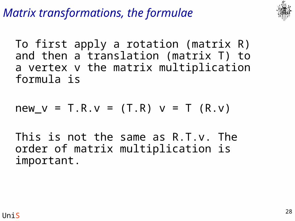
To first apply a rotation (matrix R) and then a translation (matrix T) to a vertex v the matrix multiplication formula is
new_v = T.R.v = (T.R) v = T (R.v)
This is not the same as R.T.v. The order of matrix multiplication is important.
29
UniS
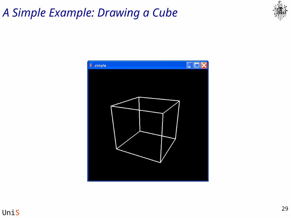
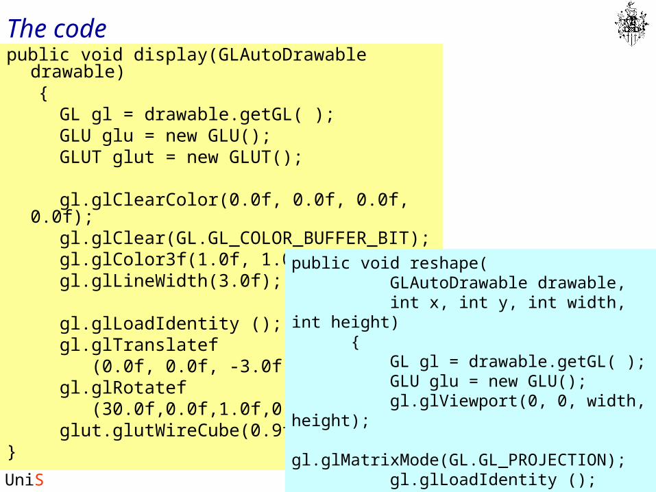
A Simple Example: Drawing a Cube
30
UniS
The codepublic void display(GLAutoDrawable drawable) { GL gl = drawable.getGL( ); GLU glu = new GLU(); GLUT glut = new GLUT(); gl.glClearColor(0.0f, 0.0f, 0.0f, 0.0f); gl.glClear(GL.GL_COLOR_BUFFER_BIT); gl.glColor3f(1.0f, 1.0f, 1.0f); gl.glLineWidth(3.0f); gl.glLoadIdentity (); gl.glTranslatef (0.0f, 0.0f, -3.0f); gl.glRotatef (30.0f,0.0f,1.0f,0.0f); glut.glutWireCube(0.9f);}
public void reshape( GLAutoDrawable drawable, int x, int y, int width, int height) { GL gl = drawable.getGL( ); GLU glu = new GLU(); gl.glViewport(0, 0, width, height); gl.glMatrixMode(GL.GL_PROJECTION); gl.glLoadIdentity (); glu.gluPerspective(50.0, 1.0, 1.0, -5.0); gl.glMatrixMode (GL.GL_MODELVIEW); }
31
UniS
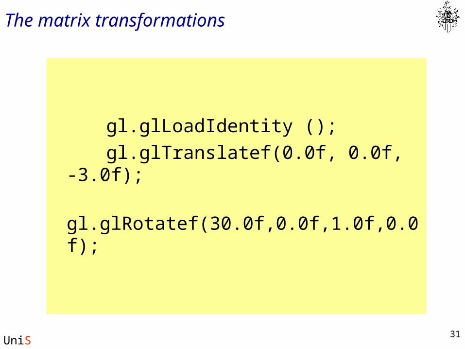
The matrix transformations
gl.glLoadIdentity ();
gl.glTranslatef(0.0f, 0.0f, -3.0f);
gl.glRotatef(30.0f,0.0f,1.0f,0.0f);
32
UniS
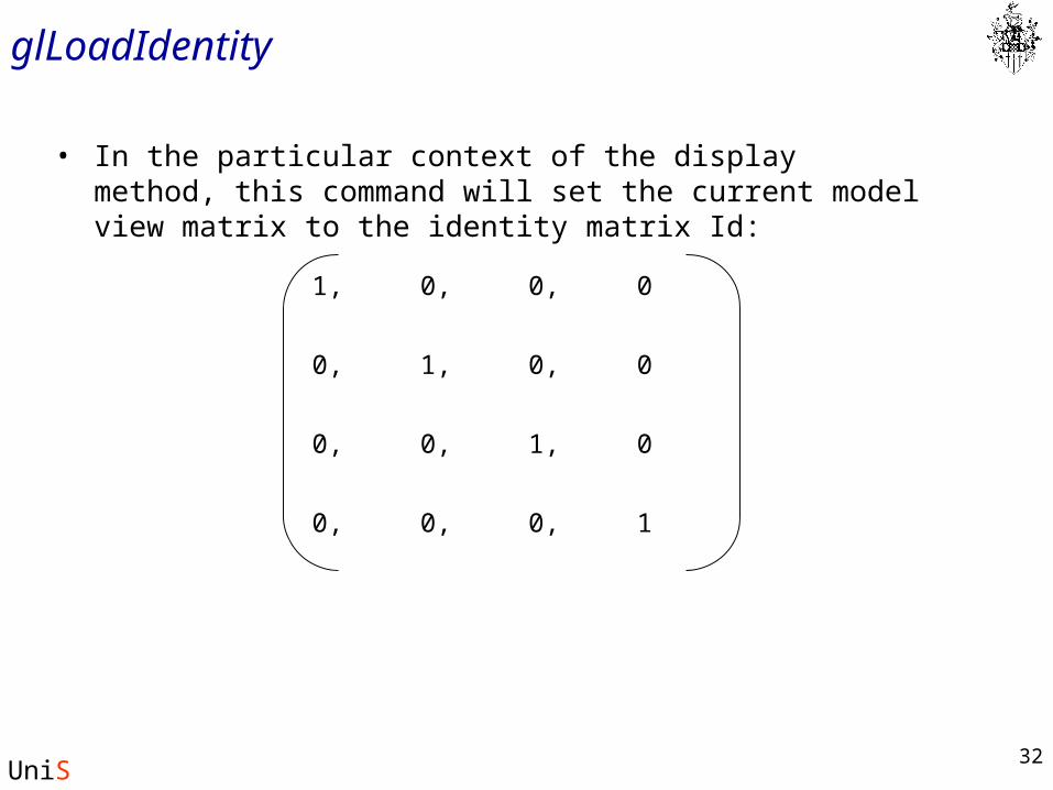
glLoadIdentity
• In the particular context of the display method, this command will set the current model view matrix to the identity matrix Id:
01,0,0,
0,
0,
0,
10,0,
01,0,
00,1,
33
UniS
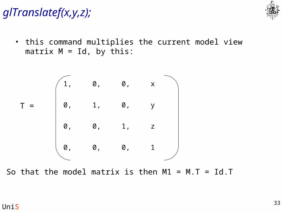
glTranslatef(x,y,z);
• this command multiplies the current model view matrix M = Id, by this:
z1,0,0,
0,
0,
0,
10,0,
y1,0,
x0,1,
T =
So that the model matrix is then M1 = M.T = Id.T
34
UniS
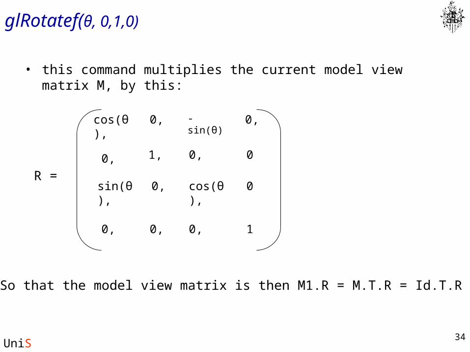
glRotatef(θ, 0,1,0)
• this command multiplies the current model view matrix M, by this:
R =
So that the model view matrix is then M1.R = M.T.R = Id.T.R
0cos(θ),
-sin(θ)
0,
0,
sin(θ),
0,
10,0,
0
cos(θ),
0,
0,
0,
1,
35
UniS
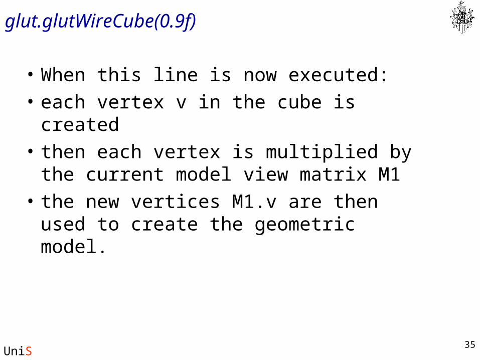
glut.glutWireCube(0.9f)
• When this line is now executed:
• each vertex v in the cube is created
• then each vertex is multiplied by the current model view matrix M1
• the new vertices M1.v are then used to create the geometric model.