Embed Size (px)
Citation preview

UNISONIC TECHNOLOGIES CO., LTD
UL82B Preliminary CMOS IC
www.unisonic.com.tw 1 of 12 Copyright © 2016 Unisonic Technologies Co., Ltd QW-R125-056.a
NON ISOLATED BUCK CONSTANT CURRENT LED DRIVER IC
DESCRIPTION
UL82B is a high precision LED BUCK constant current driver chip. The chip operates in the inductor current critical continuous mode, which is suitable for the non isolated buck LED constant current power supply with 85Vac~265Vac full range input voltage.
UL82B chip integrated 500V power switch by patent demagnetization detection technology and high voltage power supply technology, without detection and power supply for auxiliary winding, the peripheral devices are more simple, saving the cost and volume of the system.
UL82B chip with high precision current sampling circuit, while the use of patented constant current control technology to achieve high accuracy of the LED constant current output and excellent line voltage regulator. The chip operates in the critical mode of inductor current and the output current is not changed with the increase of the inductance and the working voltage of LED.
UL82B has a variety of protection features, including LED short circuit protection, under voltage protection, over temperature adjustment function and so on.
FEATURES
21
3
TO-92
1
SOT-23-3 (JEDEC TO-236)
21
3
SOT-89
1
SOT-23(JEDEC SC-59)
HSOP-8
* The integrated 500V power mos. * The integrated high voltage power supply function. * The inductor current critical continuous mode. * Without auxiliary winding detection and power supply. * The wide voltage input voltage. * ±5% LED output current accuracy. * The LED short circuit and open circuit protection. * The chip power supply under voltage protection. * The regulating function of overheating

UL82B Preliminary CMOS IC
UNISONIC TECHNOLOGIES CO., LTD 2 of 12 www.unisonic.com.tw QW-R125-056.a
ORDERING INFORMATION
Ordering Number
Lead Free Halogen Free Package Packing
UL82BL-AB3-R UL82BG-AB3-R SOT-89 Tape Reel
UL82BL-AE2-R UL82BG-AE2-R SOT-23-3 Tape Reel
UL82BL-AE3-R UL82BG-AE3-R SOT-23 Tape Reel
UL82BL-SH2-R UL82BG-SH2-R HSOP-8 Tape Reel UL82BL-T92-B UL82BG-T92-B TO-92 Tape Box
UL82BL-T92-K UL82BG-T92-K TO-92 Bulk
MARKING
SOT-23-3 / SOT-23 SOT-89
1 2 3
UL82B Date Code
HSOP-8 TO-92
UL82B Preliminary CMOS IC
UNISONIC TECHNOLOGIES CO., LTD 3 of 12 www.unisonic.com.tw QW-R125-056.a
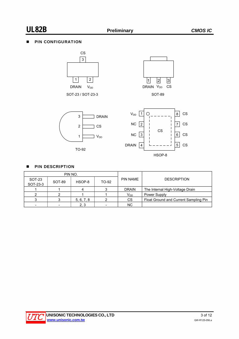
PIN CONFIGURATION
DRAIN
CS
VDD
VDDDRAIN
CS
SOT-23 / SOT-23-3
TO-92
21
3
1
2
3CS
DRAIN
1
2
3
4
8
7
6
5
CS
CS
CS
NC
NC
VDD
HSOP-8
CS
1 2 3
VDDDRAIN CS
SOT-89
PIN DESCRIPTION
PIN NO.
SOT-23 SOT-23-3
SOT-89 HSOP-8 TO-92 PIN NAME DESCRIPTION
1 1 4 3 DRAIN The Internal High-Voltage Drain
2 2 1 1 VDD Power Supply
3 3 5, 6, 7, 8 2 CS Float Ground and Current Sampling Pin
- - 2, 3 - NC

UL82B Preliminary CMOS IC
UNISONIC TECHNOLOGIES CO., LTD 4 of 12 www.unisonic.com.tw QW-R125-056.a
BLOCK DIAGRAM

UL82B Preliminary CMOS IC
UNISONIC TECHNOLOGIES CO., LTD 5 of 12 www.unisonic.com.tw QW-R125-056.a
ABSOLUTE MAXIMUM RATING (TA=25°C, Unless otherwise specified)
PARAMETER SYMBOL RATINGS UNIT
Input Voltage VIN -0.3 ~ 550 V
Supply Voltage VDD -0.3 ~ 8.5 V
SOT-23 SOT-23-3
300 mW
SOT-89 695 mW
HSOP-8 1250 mW
Power Dissipation
TO-92
PD
625 mW
Junction Temperature TJ -45 ~ +125 °C
Storage Temperature TSTG -55 ~ +150 °C
Note: Absolute maximum ratings are those values beyond which the device could be permanently damaged. Absolute maximum ratings are stress ratings only and functional device operation is not implied.
RECOMMENDED OPERATION CONDITIONS
PARAMETER SYMBOL RATINGS UNIT
Input Voltage VIN 140 ~ 375 V
Supply Voltage VDD 7 ~ 8 V
Reference Load Current ILOAD 0 ~ 200 mA
Ambient Temperature TA 0 ~ +70 °C
THERMAL CHARACTERISTICS
PARAMETER SYMBOL RATING UNIT
SOT-23 SOT-23-3
416 °C/W
SOT-89 180 °C/W
HSOP-8 100 °C/W
Junction to Ambient
TO-92
θJA
200 °C/W

UL82B Preliminary CMOS IC
UNISONIC TECHNOLOGIES CO., LTD 6 of 12 www.unisonic.com.tw QW-R125-056.a
ELECTRICAL CHARACTERISTICS (TA=25°C, Unless otherwise specified)
PARAMETER SYMBOL TEST CONDITIONS MIN TYP MAX UNIT
POWER SUPPLY SECTION
Input Voltage VIN 85 220 265 V
Chip Operating Voltage VDD DRAIN=100V 7 7.3 7.8 V
Chip Starting Voltage VDD_ON VDD rise 6 6.2 6.5 V
Chip Starting Current IST VDD=6.2V 0.5 1 2 mA
Chip Operating Current ICC 120 180 300 uA
Power Efficiency η ILED=100mA 0.88
Power Factor PF ILED=100mA 0.4 0.5 0.7
CC SECTION
The Precision of Constant Current CC ILED=0mA~200mA ±5 %
Standby Power Consumption 0.3 W
PROTECTION SECTION
Short Circuit Protection Frequency
FST VIN=220AC, RCS=3Ω 2 3 4 KHz
Current Detection Threshold VCS_TH 580 600 620 mV
Edge Blanking Time TLEB 500 ns
Turn Off Delay Time TOFF_DELAY 200 ns
TIME CONTROL SECTION
Minimum Turn Off Time TOFF_MIN 2.5 us
Maximum Turn off Time TOFF_MAX 300 us
Maximum Turn-on Time TON_MAX 40 us
POWER MOS SECTION
LDMOS Withstand Voltage BV 500 550 600 V
Conduction Resistance RON IDS=0.1A 18 Ω
TEMPER SECTION
Over Temper Adjust 140 °C
Over Temper Protect 160 °C
Over Temper Hysteresis 20 °C
Notes: 1. The parameters are not 100% tested in production. 2. The minimum, maximum range of standard specification by the test to ensure, typical values by design,
test or analysis to ensure.

UL82B Preliminary CMOS IC
UNISONIC TECHNOLOGIES CO., LTD 7 of 12 www.unisonic.com.tw QW-R125-056.a
TYPICAL APPLICATION CIRCUIT

UL82B Preliminary CMOS IC
UNISONIC TECHNOLOGIES CO., LTD 8 of 12 www.unisonic.com.tw QW-R125-056.a
TYPICAL APPLICATION CIRCUIT (Cont.)
CIN
C1
C2
AC
L0
LED
R2
3
1
2CS
DRAIN
VDD
TO-92
D1
D5
D3 D4
D2
R1
U1

UL82B Preliminary CMOS IC
UNISONIC TECHNOLOGIES CO., LTD 9 of 12 www.unisonic.com.tw QW-R125-056.a
TYPICAL APPLICATION CIRCUIT (Cont.)
BOM
Reference Component
R1 750K, 1206
R2 3Ω, 1206
C1 2.2nF / 1KV, 1206
C2 2.2nF / 50V, 0805
CIN 6.8μF, 400V
D1 ~ D4 1N4007
D5 ES1J, SMA
L0 4.7mH
U1 UL82B

UL82B Preliminary CMOS IC
UNISONIC TECHNOLOGIES CO., LTD 10 of 12 www.unisonic.com.tw QW-R125-056.a
APPLICATION INFORMATION
UL82B is a constant current driver IC for LED lighting, which is applied to the non isolated LED driver power supply.
The 500V power switch is integrated in the chip, which is based on the constant current architecture and control method, and it can achieve excellent constant current characteristics with minimal external components.
And without auxiliary winding power supply and testing, the system cost is very low.
Start After the system is powered up, the input voltage is charged on the VDD pin through the jfet, and when the VDD
voltage reaches the threshold value, the chip's internal reference circuit begins to work. When the chip is working normally, the required operating current is still through the supply of internal consumption.
Constant current control The chip is detected the peak current, and the RCS resistance is connected to the input terminal of the peak
comparator, which is compared with the threshold voltage 0.6V. When the RCS voltage reaches the threshold, the LED current is adjusted, and realized the constant current control.
The formula for calculating the inductor peak current is IPK=600/RCS (mA). Among them, RCS is a current sampling resistor. The output of the comparator CS also includes a 500ns leading edge blanking time. The formula for calculating the LED average current is ILED=IPK/2. Among them, IPK is the inductor peak current.
Protection function UL82B built in a variety of protection functions, including LED short-circuit protection, LED open circuit protection,
sampling circuit short-circuit protection, temperature regulation and protection, etc. When LED short circuit, the system works in the 3 KHz low frequency, so the power consumption is very low.
Over temperature adjustment function UL82B has the function of over temperature adjustment, the output current is gradually reduced when the driving
power is over, so that the output power and temperature rise is controlled, the power supply is maintained at the set value, In order to improve the reliability of the system, the chip is internally set to adjust the temperature of the 140°C.
PCB design In the design of PCB, you need to follow the following guidelines: VDD bypass capacitor is required to close the VDD pin of the chip. RCS resistor requires close to the CS pin of the chip Between RCS and VDD bypass capacitor resistor connected to the copper foil as short as possible CS pin increases in the area of copper clad to improve chip cooling.

UL82B Preliminary CMOS IC
UNISONIC TECHNOLOGIES CO., LTD 11 of 12 www.unisonic.com.tw QW-R125-056.a
TEST CIRCUIT
Table 1. Efficiency and power factor test
VI pF VO (V) IO (A) Pi (W) η
85V --- 61 0.0962 6.6 88.91%
115V 0.552 61 0.1031 7.04 89.33%
132V --- 60.4 0.102 6.92 89.03%
180V --- 117 0.1026 12.9 93.06%
230V 0.496 116 0.1008 12.65 92.43%
264V --- 116 0.1006 12.64 92.32%
Table 2. Line Regulation & Load Regulation test
VLED VIN
60V 80V 120V Load Regulation%
180VAC 0.1042 0.104 0.1042 ±0.1%
230VAC 0.1043 0.1038 0.1021 ±1.1%
264VAC 0.1045 0.1038 0.1017 ±1.4%
Line Regulation% ±0.15% ±0.1% ±1.25%
Crucial waveforms
VIN=115V, fSW=33KHZ VIN=230V, fSW=66KHZ
Short circuit protection test Over-temperature protection test

UL82B Preliminary CMOS IC
UNISONIC TECHNOLOGIES CO., LTD 12 of 12 www.unisonic.com.tw QW-R125-056.a
TYPICAL CHARACTERISTICS
L
N
6.8μFES1J
4.7mH
2.2nF750K
3Ω2.2nF
U1
CS
VDD
DRAIN
1
2
3
UTC assumes no responsibility for equipment failures that result from using products at values that exceed, even momentarily, rated values (such as maximum ratings, operating condition ranges, or other parameters) listed in products specifications of any and all UTC products described or contained herein. UTC products are not designed for use in life support appliances, devices or systems where malfunction of these products can be reasonably expected to result in personal injury. Reproduction in whole or in part is prohibited without the prior written consent of the copyright owner. UTC reserves the right to make changes to information published in this document, including without limitation specifications and product descriptions, at any time and without notice. This document supersedes and replaces all information supplied prior to the publication hereof.