Embed Size (px)
Citation preview

National Chiao Tung University Physics Experimental Handout Basic Electricity I 2-1
Unit-02 Basic Electricity I
Objective:
In this experiment, we would like to get you familiar with the theorem, structure and use
of multimeter and learn the measurement of Alternating Current (AC) / Direct Current (DC)
signals.
Apparatus:
Digital multimeter, power supply, function generator, breadboard, resistance
Principle:
In physics experiments, we usually use precision instruments to measure the physics
quantities, with the most common being in voltage and current measurement. The multimeter
is a multipurpose tool for measuring the current, voltage, and resistance. With Ohm’s law, we
can know the resistance of a resistor by measuring the current under specific voltage. The
design is based on D'arsonval galvanometer. The followings are principles of kinds of
measurements.
A. D'arsonval galvanometer
The top view of D'arsonval galvanometer is shown in Fig.1, when current I passes
through flexible coil, it generates magnetic field. This generated magnetic field, which
interacts with the permanent magnet, would cause a clockwise torque 1L , in proportion to
current I. It can be expressed as the following equation:
IKL 11 1K is the proportion constant
This torque would cause the rotation of the coil. The twist of upper and lower springs
causes the anticlockwise torque2L . It can be expressed as the following equation:
22 KL 2K is the proportion constan
When the two torques L1 and L2 hit a balance, the coil would stay at a specific angle
21 LL or 21 KIK

National Chiao Tung University Physics Experimental Handout Basic Electricity I 2-2
Figure 1. Principle of D'arsonval galvanometer
Assume 1
2
K
KK
So, we can get KI
Therefore, we can find the current value by measuring the angle of the indicator.
As is shown in Figure 2, there are two types of power supply: direct current (DC) and
alternating current (AC). The current and voltage of direct current always stay constant. They
would not vary with time. The current and voltage of alternating current would vary cyclically
with time. Thus, the circuit would act differently when you supply these two kinds of power
source.
Figure 2. AC/DC signals in relation to time

National Chiao Tung University Physics Experimental Handout Basic Electricity I 2-3
To explicate the differences, take electric power as an example:
(a) Direct Current (DC)
If a resistor R is supplied by direct current I, the average power P would be
RIP 2
(b) Alternating Current (AC)
If a resistor R is supplied by alternating current T/tsinII m 2 , the average power P
would be
Tm
T
m dtT
tcos
T
RIdt
T
tsinIR
TP
0
22
0 2
41
21
= 222
0
2
228
4
2rms
mm
T
m IRRIT
T
RIT
tsinT
t
T
RI
mI is the maximum current and T is the period
In figure 3, we can see that the average power of alternating current has an additional
factor 1/2. In order to unify the formula of alternating current and direct current, we define an
effective current rmsI (root mean square of current) to describe the total effect of alternating
current. Similarly, we can define an effective voltage (root mean square of voltage).
Figure 3. Root mean square of voltage

National Chiao Tung University Physics Experimental Handout Basic Electricity I 2-4
When measuring the alternating voltage and alternating current, the values on multimeter
are rmsV and
rmsI .
Root mean square of voltage maxmax 707.02
VV
Vrms
Root mean square of current maxmax 707.02
II
I rms
B. Ammeter – current measurement
As shown in Figure 4, when a galvanometer is used as an ammeter, a shunt resistor R is
connected in parallel with the galvanometer. Assume the internal resistance of galvanometer
is Rg, the maximum direct current which passes through the ammeter is I, and the maximum
direct current which passes through the galvanometer is If. According to Ohm’s Law, the
value of the shunt resistance S is determined by
g
f
f
ffg RII
ISSIIIR
Thus, the measurement gear of the DC ammeter varies in accordance with shunt resistance S.
Figure 4. DC Ammeter
For AC ammeter, it is formed with a galvanometer, a small resistor, and a rectifier. (A
diode has the characteristic of low resistance under forward bias and high resistance under
reverse bias.) Since D'arsonval galvanopmeter can only work with direct current, a rectifier is
required to transform alternative current into direct current. Insert a rectifier into the left side
of node a in figure 5 and it can be an AC ammeter. But please remember that the dial scale of
an AC ammeter is the peak current times 0.707( 21 ).
National Chiao Tung University Physics Experimental Handout Basic Electricity I 2-5
Figure 5. AC Ammeter
C. Voltmeter – voltage measurement
As shown in Figure 6, when a galvanometer is used as a voltmeter, a resistor R is
connected in series with the galvanometer. Assume the highest voltage measured by
galvanometer is Vm, the current at this time is Im, the internal resistance of the galvanometer is
Rg and the highest voltage to measure is NVV m , the resistor R we need to connect in series
can be determined by
mgm IRV
mgm IRRNVV )(
then
NR I R R Ig m g m ( )
R N Rg ( )1
For AC voltmeter, it would be the same as DC voltmeter except that it requires one more
rectifier and the dial scale is defined by multiplying 0.707.
Figure 6. DC Voltmeter

National Chiao Tung University Physics Experimental Handout Basic Electricity I 2-6
D. Resistance measurement
With Ohm’s law, we can know the resistance by measuring the current under specific
voltage. The amount of resistance can be determined as the following
RV
I (Ohm’s Law)
Remarks:
1. The rotary switch should be placed in the right position and no any changeover off of
range shall be made during measurement is conducted to prevent damage of the Meter.
2. When measuring voltage, the multimeter should be in parallel with the circuit.
3. When measuring current, the multimeter should be in series with the circuit.
4. Never measure the voltage by current gear. If you do, it will cause fire and people might
get hurt.
5. To avoid damage to the equipment, the output voltage of the power supply must not
exceed 10.0 V.
Procedure:
Preparation
1. Before measurement, read user guide of power supply, function generator and
breadboard.
2. Scale switch:Switch to the proper gear when measuring voltage or current. You
should start with the maximum gear down to the minimum.
3. Turn the multimeter off when it is not in use to prevent the battery from dying.
A. DC voltage, current and resistance measurement
1. Choose any two resistances and connect in series on the breadboard. Record R1 and R2
resistance values.
2. Set the multimeter to resistance gear, make sure that the sensor is properly connected,
use the senor to touch the two ends of the resistance, and record the values of R1 and
R2 based on color code table.
3. Set up the circuit in series and parallel on Breadboard, as indicated in Figure 7.
4. Supply direct voltage power (< 10.0V) to series circuit and parallel circus respectively.
5. Turn on the multimeter and press blue button, and then switch to DC measurement.
6. Set the multimeter to voltage gear and record the total voltage and the shunt voltage
with the Meter connected in parallel.
7. Set the multimeter to current gear (from high to low) and record the total current and
the shunt current with the multimeter connected in series.
National Chiao Tung University Physics Experimental Handout Basic Electricity I 2-7
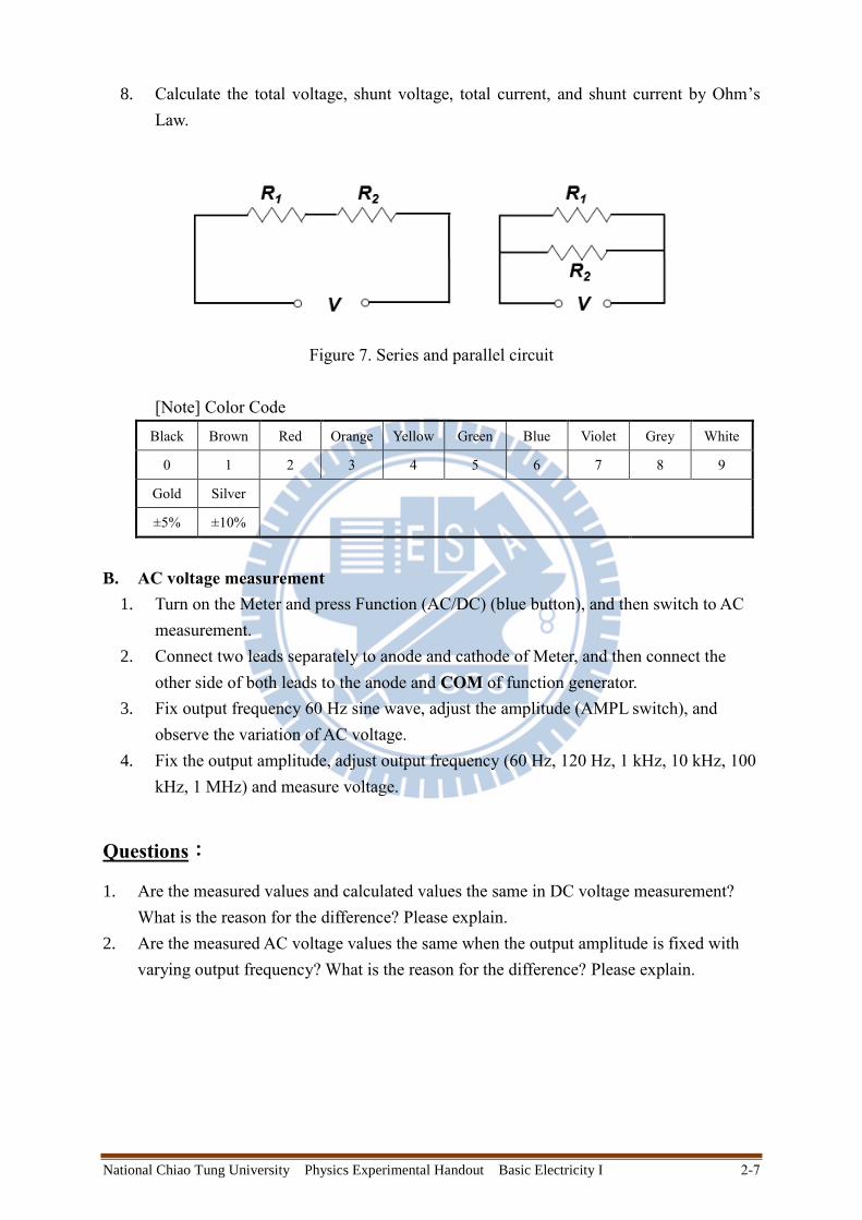
8. Calculate the total voltage, shunt voltage, total current, and shunt current by Ohm’s
Law.
Figure 7. Series and parallel circuit
[Note] Color Code
Black Brown Red Orange Yellow Green Blue Violet Grey White
0 1 2 3 4 5 6 7 8 9
Gold Silver
±5% ±10%
B. AC voltage measurement
1. Turn on the Meter and press Function (AC/DC) (blue button), and then switch to AC
measurement.
2. Connect two leads separately to anode and cathode of Meter, and then connect the
other side of both leads to the anode and COM of function generator.
3. Fix output frequency 60 Hz sine wave, adjust the amplitude (AMPL switch), and
observe the variation of AC voltage.
4. Fix the output amplitude, adjust output frequency (60 Hz, 120 Hz, 1 kHz, 10 kHz, 100
kHz, 1 MHz) and measure voltage.
Questions:
1. Are the measured values and calculated values the same in DC voltage measurement?
What is the reason for the difference? Please explain.
2. Are the measured AC voltage values the same when the output amplitude is fixed with
varying output frequency? What is the reason for the difference? Please explain.