Embed Size (px)
Citation preview
8/8/2019 Unit 1- 2 & 16 Marks
http://slidepdf.com/reader/full/unit-1-2-16-marks 1/26
UNIT I-DATA COMMUNICATION
PART A
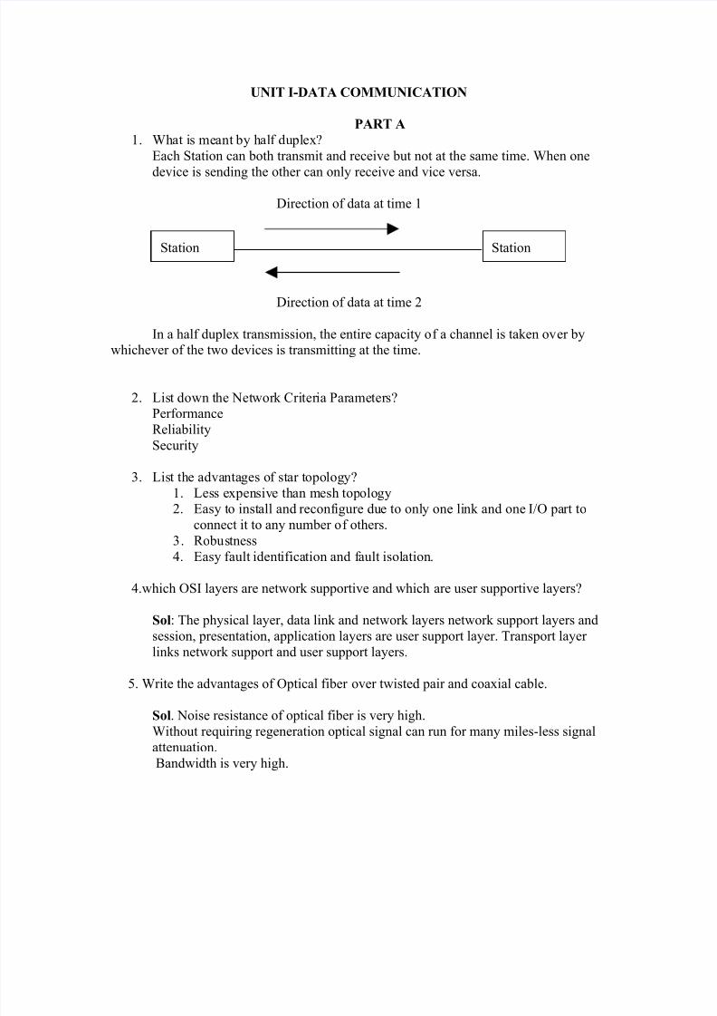
1. What is meant by half duplex?
Each Station can both transmit and receive but not at the same time. When one
device is sending the other can only receive and vice versa.
Direction of data at time 1
Direction of data at time 2
In a half duplex transmission, the entire capacity of a channel is taken over by
whichever of the two devices is transmitting at the time.
2. List down the Network Criteria Parameters?Performance
Reliability
Security
3. List the advantages of star topology?
1. Less expensive than mesh topology2. Easy to install and reconfigure due to only one link and one I/O part to
connect it to any number of others.3. Robustness
4. Easy fault identification and fault isolation.
4.which OSI layers are network supportive and which are user supportive layers?
Sol: The physical layer, data link and network layers network support layers and
session, presentation, application layers are user support layer. Transport layer
links network support and user support layers.
5. Write the advantages of Optical fiber over twisted pair and coaxial cable.
Sol. Noise resistance of optical fiber is very high.
Without requiring regeneration optical signal can run for many miles-less signal
attenuation.
Bandwidth is very high.
Station Station
8/8/2019 Unit 1- 2 & 16 Marks
http://slidepdf.com/reader/full/unit-1-2-16-marks 2/26
6. what is peer to peer process?
Sol. Between machines layer-x on one machine can communicate with layer-x of another machine. The process on each machine that communicate at a given layer
are called peer to peer process.
7.What is modem and give its various standards.
The word modem is a composite word that refers to the two functional entities that make
device: A signal modulator and a signal demodulator.A modulator creates a bandpass analo
from binary data and a demodulator recovers the binary data from the modulated signal.
Its standards are v.32,v.32bis,v.34,v.70,v.90
8.Discuss about the voltage levels of RS-232 standard.
The RS-232 standard defines the voltage levels that correspond to logical one and logical zero
Valid signals are plus or minus 3 to 15 volts. The range near zero volts is not a valid RS-23
logic one is defined as a negative voltage, the signal condition is called marking, and
functional significance of OFF. Logic zero is positive, the signal condition is spacing, andfunction ON.
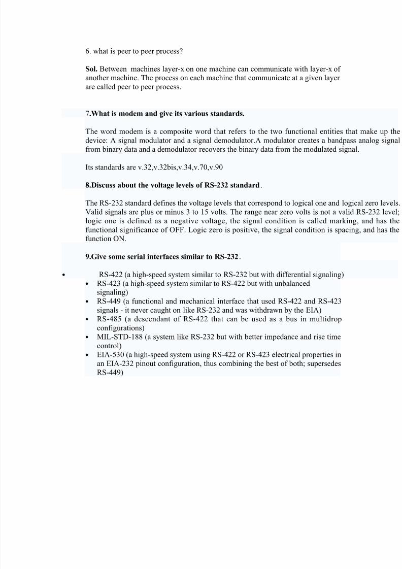
9.Give some serial interfaces similar to RS-232.
• RS-422 (a high-speed system similar to RS-232 but with differential signaling)
• RS-423 (a high-speed system similar to RS-422 but with unbalanced
signaling)• RS-449 (a functional and mechanical interface that used RS-422 and RS-423
signals - it never caught on like RS-232 and was withdrawn by the EIA)
• RS-485 (a descendant of RS-422 that can be used as a bus in multidrop
configurations)
• MIL-STD-188 (a system like RS-232 but with better impedance and rise time
control)• EIA-530 (a high-speed system using RS-422 or RS-423 electrical properties in
an EIA-232 pinout configuration, thus combining the best of both; supersedes
RS-449)

8/8/2019 Unit 1- 2 & 16 Marks
http://slidepdf.com/reader/full/unit-1-2-16-marks 3/26
PART B-UNIT I
1. Explain the mesh and star topologies of the Network in detail with diagram.
Sol:Physical Topology:It refers to the way in which a network is laid out physically.
Two or more links form a topology. The topology of a network is the geometric
representation of all the links and linking devices (nodes) to one another. There arefour basic topologies possible:
Mesh, Star, Bus and Ring.
Categories of Topology
Mesh:
In this topology every device has a dedicated point-to-point link to every other device. The term dedicated means that the link carries traffic only between the two
devices it connects. To find the number of physical links in a fully connected meshnetwork with n nodes we need
i.e. each and every node must be connected to n-1 nodes if each physical link allows communication in both direction, we can divide the no of links by 2
Topology
Mesh Star Bus Ring
n (n-1)/2

8/8/2019 Unit 1- 2 & 16 Marks
http://slidepdf.com/reader/full/unit-1-2-16-marks 4/26
Advantages:
1. Dedicated links guarantees that each connection can carry its own load thuseliminating the traffic problems that an occur when links must be shared bymultiple devices.
2. It is robust.
3. Privacy or Security4. Fault identification and fault isolation easy.
Disadvantages:1. The amount of cabling and number of I/O parts required.
2. The hardware required to connect to each link can be expensive.
Star Topology:In this each device has a dedicated point-to-point link only to a central controller
usually called a hub. Star topology does not allow direct traffic between devices. The
controller acts as an exchange. If one device wants t send data to another it sends data tothe controller, which then relays the data to the other connected device.
Advantages:1. Less expensive than mesh topology.
2. Easy to install and reconfigure due to only one link and one I/O part to connect it
to any number of others.3. Robustness
4. Easy fault identification and fault isolation.
Disadvantages:1. Dependency of the whole topology on one single point, the hub. If the hub goes
down, the whole system is dead.
2. Cabling required more than bus and ring.
Station
Station Station
Station Station
8/8/2019 Unit 1- 2 & 16 Marks
http://slidepdf.com/reader/full/unit-1-2-16-marks 5/26
Start Topology is used in LAN’s and High speed LAN’s.
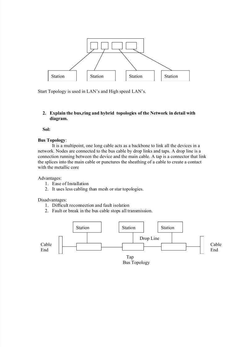
2. Explain the bus,ring and hybrid topologies of the Network in detail with
diagram.
Sol:
Bus Topology:
It is a multipoint, one long cable acts as a backbone to link all the devices in anetwork. Nodes are connected to the bus cable by drop links and taps. A drop line is a
connection running between the device and the main cable. A tap is a connector that link
the splices into the main cable or punctures the sheathing of a cable to create a contactwith the metallic core
Advantages:1. Ease of Installation2. It uses less cabling than mesh or star topologies.
Disadvantages:1. Difficult reconnection and fault isolation
2. Fault or break in the bus cable stops all transmission.
Tap
Bus Topology
Station Station Station Station
Cable
End
Cable
End
Station Station Station
Drop Line

8/8/2019 Unit 1- 2 & 16 Marks
http://slidepdf.com/reader/full/unit-1-2-16-marks 6/26
Ring Topology:In a ring topology each device has a dedicated point-to-point link with
only the two devices on either side of it A Signal is passed along the ring in one direction
from device to device until it reaches its destination. Each device in the ring incorporatesa repeater. When a device receives a signal intended for another device, its repeater
regenerates the bits and passes them along.
Advantages:
1. Easy to install and reconfigure.2. Fault isolation is simplified.
Disadvantages:
1. Unidirectional traffic.
2. A break in the ring can disable the entire network.
StationStation
Repeater
Station Station
Station Station

8/8/2019 Unit 1- 2 & 16 Marks
http://slidepdf.com/reader/full/unit-1-2-16-marks 7/26
Hybrid Topology:
A network can be hybrid. We can have a main star topology with each
branch connecting several stations in a bus topology.
3. Explain the following:
1.Protocols and standards
2.Line configuration
Sol:
1.Protocols:
The protocol is a set of rules that govern data communication;the key elementsof a protocol or syntax ,semantics and timing.
Syntax:
It refers to the structure or format of the data,meaning the order in which they are presented.
Semantics:
It refers to the meaning of each section of bit
Station Station Station
Station Station Station
Station Station Station
Hub
8/8/2019 Unit 1- 2 & 16 Marks
http://slidepdf.com/reader/full/unit-1-2-16-marks 8/26
Timing:
It refers to two characteristics :when data should be sent and how fast they can be
sent.
Standards:
It provides a model for development that makes it possible for a product to work
regardless of the individual manufacturers .They are essential in creating and maintainingan open and competitive market for equipment manufacturer.
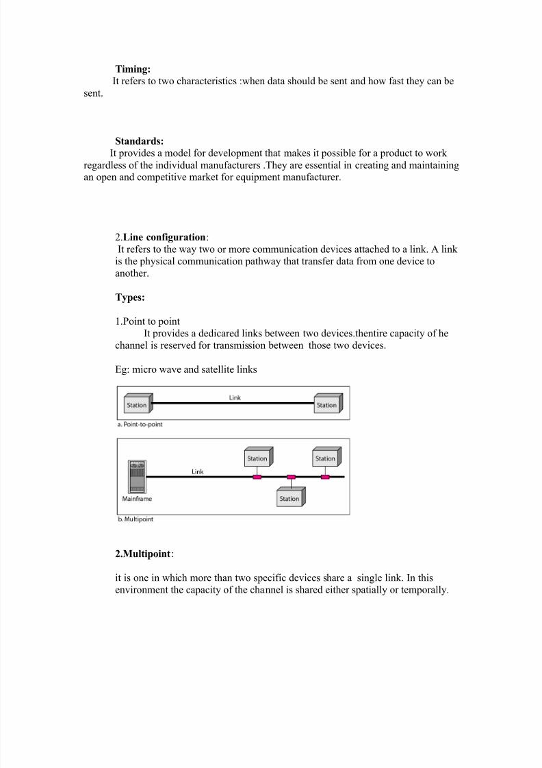
2.Line configuration:
It refers to the way two or more communication devices attached to a link. A link
is the physical communication pathway that transfer data from one device toanother.
Types:
1.Point to point
It provides a dedicared links between two devices.thentire capacity of hechannel is reserved for transmission between those two devices.
Eg: micro wave and satellite links
2.Multipoint:
it is one in which more than two specific devices share a single link. In thisenvironment the capacity of the channel is shared either spatially or temporally.
8/8/2019 Unit 1- 2 & 16 Marks
http://slidepdf.com/reader/full/unit-1-2-16-marks 9/26
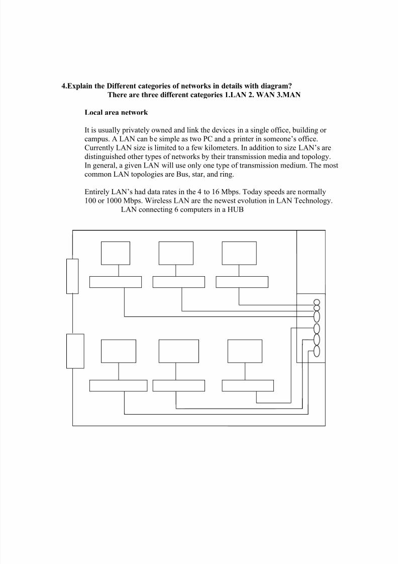
4.Explain the Different categories of networks in details with diagram?
There are three different categories 1.LAN 2. WAN 3.MAN
Local area network
It is usually privately owned and link the devices in a single office, building or
campus. A LAN can be simple as two PC and a printer in someone’s office.
Currently LAN size is limited to a few kilometers. In addition to size LAN’s are
distinguished other types of networks by their transmission media and topology.In general, a given LAN will use only one type of transmission medium. The most
common LAN topologies are Bus, star, and ring.
Entirely LAN’s had data rates in the 4 to 16 Mbps. Today speeds are normally100 or 1000 Mbps. Wireless LAN are the newest evolution in LAN Technology.
LAN connecting 6 computers in a HUB
8/8/2019 Unit 1- 2 & 16 Marks
http://slidepdf.com/reader/full/unit-1-2-16-marks 10/26
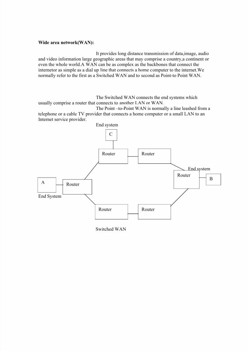
Wide area network(WAN):
It provides long distance transmission of data,image, audio
and video information large geographic areas that may comprise a country,a continent or even the whole world.A WAN can be as complex as the backbones that connect the
internetor as simple as a dial up line that connects a home computer to the internet.We
normally refer to the first as a Switched WAN and to second as Point-to Point WAN.
The Switched WAN connects the end systems whichusually comprise a router that connects to another LAN or WAN.
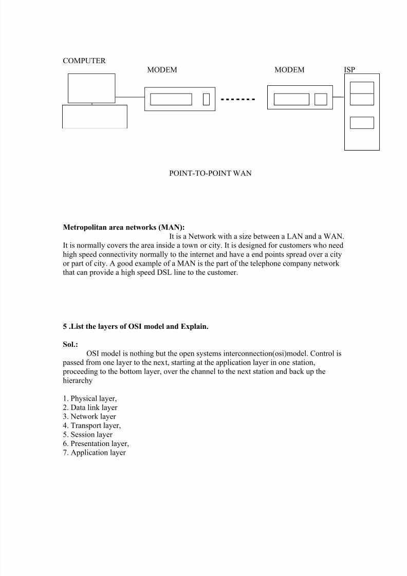
The Point –to-Point WAN is normally a line leashed from a
telephone or a cable TV provider that connects a home computer or a small LAN to an
Internet service provider. End system
End system
End System
Switched WAN
A Router
Router Router
Router Router
Router B
C
8/8/2019 Unit 1- 2 & 16 Marks
http://slidepdf.com/reader/full/unit-1-2-16-marks 11/26
COMPUTER
MODEM MODEM ISP
POINT-TO-POINT WAN
Metropolitan area networks (MAN):
It is a Network with a size between a LAN and a WAN.It is normally covers the area inside a town or city. It is designed for customers who need
high speed connectivity normally to the internet and have a end points spread over a city
or part of city. A good example of a MAN is the part of the telephone company network that can provide a high speed DSL line to the customer.
5 .List the layers of OSI model and Explain.
Sol.:
OSI model is nothing but the open systems interconnection(osi)model. Control is passed from one layer to the next, starting at the application layer in one station,
proceeding to the bottom layer, over the channel to the next station and back up the
hierarchy
1. Physical layer,2. Data link layer 3. Network layer
4. Transport layer,
5. Session layer
6. Presentation layer,7. Application layer

8/8/2019 Unit 1- 2 & 16 Marks
http://slidepdf.com/reader/full/unit-1-2-16-marks 12/26
Application(Layer 7):
This layer supports application and end-user processes. Communication partners
are identified, quality of service is identified, user authentication and privacy areconsidered, and any constraints on data syntax are identified. Everything at this layer is
application-specific. This layer provides application services for file transfers, e-mail, and
other network software services. Telnet and FTP are applications that exist entirely in theapplication level. Tiered application architectures are part of this layer.
Presentation(Layer 6):
This layer provides independence from differences in data representation (e.g.,
encryption) by translating from application to network format, and vice versa. The presentation layer works to transform data into the form that the application layer can
accept. This layer formats and encrypts data to be sent across a network, providingfreedom from compatibility problems. It is sometimes called the syntax layer .
8/8/2019 Unit 1- 2 & 16 Marks
http://slidepdf.com/reader/full/unit-1-2-16-marks 13/26
Session(Layer 5):
This layer establishes, manages and terminates connections between applications.
The session layer sets up, coordinates, and terminates conversations, exchanges, and
dialogues between the applications at each end. It deals with session and connectioncoordination.
Transport(Layer 4):
This layer provides transparent transfer of data between end systems, or hosts, and
is responsible for end-to-end error recovery and flow control. It ensures complete datatransfer.
Network(Layer 3):
This layer provides switching and routing technologies, creating logical paths,known as virtual circuits, for transmitting data from node to node. Routing and
forwarding are functions of this layer, as well as addressing, internetworking, error
handling, congestion control and packet sequencing.
Data Link(Layer 2):
At this layer, data packets are encoded and decoded into bits. It furnishes
transmission protocol knowledge and management and handles errors in the physical
layer, flow control and frame synchronization. The data link layer is divided into twosublayers: The Media Access Control (MAC) layer and the Logical Link Control (LLC)
layer. The MAC sublayer controls how a computer on the network gains access to the
data and permission to transmit it. The LLC layer controls frame synchronization, flowcontrol and error checking.
physical(Layer 1):
This layer conveys the bit stream - electrical impulse, light or radio signal -- through the
network at the electrical and mechanical level. It provides the hardware means of sendingand receiving data on a carrier, including defining cables, cards and physical aspects. Fast
Ethernet, RS232, and ATM are protocols with physical layer components.

8/8/2019 Unit 1- 2 & 16 Marks
http://slidepdf.com/reader/full/unit-1-2-16-marks 14/26
Application layer
Presentation layer
Session layer transport layer
network layer
datalink layer
physical layer
8/8/2019 Unit 1- 2 & 16 Marks
http://slidepdf.com/reader/full/unit-1-2-16-marks 15/26
6. Write about Guided Transmission media.
Sol: Computers and other telecommunication devices use signals to represent data. these
signals are transmitted from one device to another in the form of electromagnetic energy.
these electromagnetic signals can travel through vaccum,air or other transmission media.
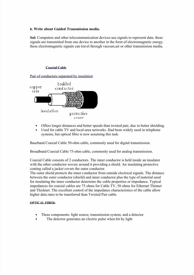
Coaxial Cable
Pair of conductors separated by insulation
• Offers longer distances and better speeds than twisted pair, due to better shielding.
• Used for cable TV and local-area networks. Had been widely used in telephone
systems, but optical fibre is now assuming this task.
Baseband Coaxial Cable 50-ohm cable, commonly used for digital transmission.
Broadband Coaxial Cable 75-ohm cable, commonly used for analog transmission.
Coaxial Cable consists of 2 conductors. The inner conductor is held inside an insulator with the other conductor woven around it providing a shield. An insulating protective
coating called a jacket covers the outer conductor.
The outer shield protects the inner conductor from outside electrical signals. The distance between the outer conductor (shield) and inner conductor plus the type of material used
for insulating the inner conductor determine the cable properties or impedance. Typical
impedances for coaxial cables are 75 ohms for Cable TV, 50 ohms for Ethernet Thinnet
and Thicknet. The excellent control of the impedance characteristics of the cable allowhigher data rates to be transferred than Twisted Pair cable.
OPTICAL FIBER:
• Three components: light source, transmission system, and a detector
• The detector generates an electric pulse when hit by light

8/8/2019 Unit 1- 2 & 16 Marks
http://slidepdf.com/reader/full/unit-1-2-16-marks 16/26
• 1-a pulse of light; 0-missing pulse of light.
• optical rays travel in glass or plastic core
• When light move from one medium to another it bend at the boundary. The
amount of bending depends on the properties of the media.
• Light at shallow angles propagate along the fibre, and those that are less thancritical angle are absorbed in the jacket
• The cladding is a glass or plastic with properties that differ from those of the core
• Used in long distance communication, in locations having small amount of space,and with reduction in price is starting to get also to LANs.
• Not affected by external electromagnetic fields, and do not radiate energy. Hence,
providing high degree of security from eavesdropping.
•
Provide for multimode of propagation at different angles of reflections. Causesignal elements to spread out in time, which limits the rate in which data can be
accurately received.
• Reduction of the radius of the core implies less reflected angles. Single mode isachieved with sufficient small radius.
• A multimode graded index transmission is obtained by varying the index of
reflection of the core to improve on the multi mode option without resolving tothe cost of single mode. (index of reflection=speed in vacuum / speed in medium.)
.
Coaxial cable 500 Mbps 350 MHz 1-10 kmoptical fibre 2 Gbps 2 GHz 10-100 km

8/8/2019 Unit 1- 2 & 16 Marks
http://slidepdf.com/reader/full/unit-1-2-16-marks 17/26
7.Explain in detail about MODEM .
Modem:
Modem (from modulate and demodulate) is a device that modulates an analog carrier signal to
digital information, and also demodulates such a carrier signal to decode the transmitted informatigoal is to produce a signal that can be transmitted easily and decoded to reproduce the original digit
Modems can be used over any means of transmitting analog signals, from driven diodes to radio. M
are generally classified by the amount of data they can send in a given time, normally measured in second, or "bps". They can also be classified by Baud, the number of distinct symbols transmit
second; these numbers are directly connected, but not necessarily in linear fashion .
There are different V series standards:
V.21 V.22 V.22bis
Voiceband modems generally remained at 300 and 1200 bit/s (V.21 and V.22) into the mid 1980s, alover this period, the acoustic coupler disappeared, seemingly overnight, as Smartmodem-com
modems flooded the market.A V.22bis 2400-bit/s system similar in concept to the 1200-bit/s B
signalling was introduced in the U.S., and a slightly different, and incompatible, one in Europe. By 1980s, most modems could support all of these standards, and 2400-bit/s operation was becoming co
V.32
Echo cancellation was the next major advance in modem design. Local telephone lines use the same
send and receive, while longer distances use separate wires for the two directions. A small amoun
outgoing signal bounces back. This signal can confuse the modem: is the signal it is "hearing" frremote modem, or its own transmission bouncing back? This was why earlier modems split the
frequencies into answer and originate; each modem simply didn't listen to its own transmitting frequ
Even with improvements to the phone system allowing higher speeds, this splitting of available phon bandwidth still imposed a half-speed limit on modems.Echo cancellation got around this p

8/8/2019 Unit 1- 2 & 16 Marks
http://slidepdf.com/reader/full/unit-1-2-16-marks 18/26
Measuring the echo delays and magnitudes allowed the modem to tell if the received signal was fro
or the remote modem, and create an equal and opposite signal to cancel its own. Modems were then
send at "full speed" in both directions at the same time, leading to the development of the 9600 bitstandard.
V.34
Any interest in these systems was destroyed during the lengthy introduction of the 28,800 bit
standard. While waiting, several companies decided to "jump the gun" and introduced modems they to as "V.FAST". In order to guarantee compatibility with V.34 modems once the standard was
(which happened in 1994), the manufacturers were forced to use more "flexible" parts, generally a D
microcontroller, as opposed to purpose-designed "modem chips".
Eventually the V.34 standard was updated to increase the maximum speed from 28.8 to 33.8 kbit/was and still is the fastest speed using analog technology. Later modems achieved faster rates vi
digital encoding (PCM).
V.70
In 1995, the first DSVD (Digital Simultaneous Voice and Data) modems became available to conand the standard was ratified as V.70 by the ITU in 1996.V.70 compatible modems allow for a ma
speed of 33.6 kbit/s between peers. By using a majority of the bandwidth for data and reserving
voice transmission, DSVD modems allow users (often while playing video games) to pick up a te
handset interfaced with the modem, and initiate a call to the other peer.
V.90
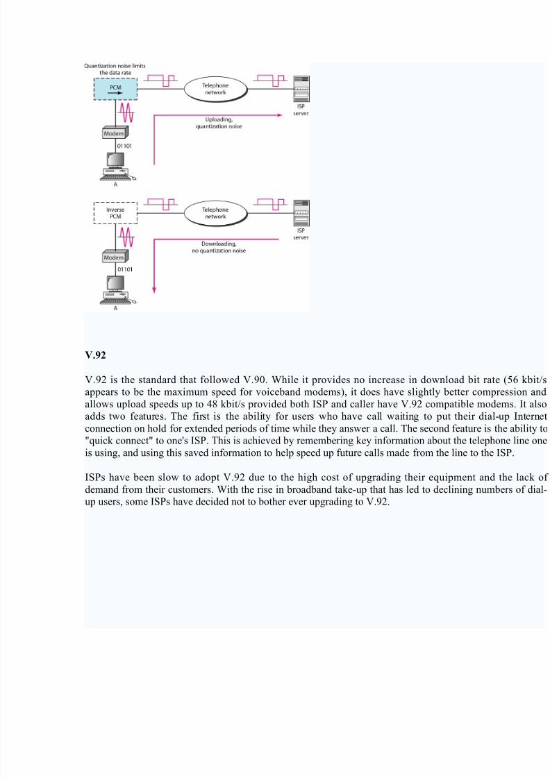
A standardization effort started around 1996 working towards a single standard for 56k modems.Thcertain special requirements and restrictions associated with V.90 modems.An important restricti
V.90 is that while V.90 modems can obtain up to 56 kbit/s download speeds, they are limited to 33.upload speeds. Only in the rarest of circumstances would a user actually see 56 kbit/s speeds, with 4
to 50 kbit/s being the most likely on a clean line. In addition, the FCC has limited the power outp
modems to prevent crosstalk between bundled phone lines; thus even on a clean line 56K modelimited to approximately 53 kbit/s to stay compliant with the regulation.
8/8/2019 Unit 1- 2 & 16 Marks
http://slidepdf.com/reader/full/unit-1-2-16-marks 19/26
V.92
V.92 is the standard that followed V.90. While it provides no increase in download bit rate (5appears to be the maximum speed for voiceband modems), it does have slightly better compress
allows upload speeds up to 48 kbit/s provided both ISP and caller have V.92 compatible modemsadds two features. The first is the ability for users who have call waiting to put their dial-up
connection on hold for extended periods of time while they answer a call. The second feature is the a"quick connect" to one's ISP. This is achieved by remembering key information about the telephone
is using, and using this saved information to help speed up future calls made from the line to the ISP.
ISPs have been slow to adopt V.92 due to the high cost of upgrading their equipment and the
demand from their customers. With the rise in broadband take-up that has led to declining numbers up users, some ISPs have decided not to bother ever upgrading to V.92.

8/8/2019 Unit 1- 2 & 16 Marks
http://slidepdf.com/reader/full/unit-1-2-16-marks 20/26
8.Discuss about RS232 interfacing sequences.
RS-232 INTERFACING SEQUENCES[EIA 232]
EIA 232 defines the mechanical,electrical and functional characteristics of the interface betwDTE and DCE.
Voltage levels:
The RS-232 standard defines the voltage levels that correspond to logical one and logical zero level
signals are plus or minus 3 to 15 volts. The range near zero volts is not a valid RS-232 level; logi
defined as a negative voltage, the signal condition is called marking, and has the functional significOFF. Logic zero is positive, the signal condition is spacing, and has the function ON. The standard sp
a maximum open-circuit voltage of 25 volts; signal levels of ±5 V,±10 V,±12 V, and ±15 V
commonly seen depending on the power supplies available within a device. RS-232 drivers and remust be able to withstand indefinite short circuit to ground or to any voltage level up to +/-25 vol
slew rate, or how fast the signal changes between levels, is also controlled.
Because the voltage levels are higher than logic levels used by integrated circuits, special intervening
are required to translate logic levels, and to protect circuitry internal to the device from short cirtransients that may appear on the RS-232 interface.Because both ends of the RS-232 circuit depend
ground pin being zero volts, problems will occur when connecting machinery and computers wh
voltage between the ground pin on one end, and the ground pin on the other is not zero. This may als
a hazardous ground loop.
Connectors:
RS-232 devices may be classified as Data Terminal Equipment (DTE) or Data Circuit termEquipment (DCE); this defines at each device which wires will be sending and receiving each sign
standard recommended but did not make mandatory the D-subminiature 25 pin connector. In g
terminals have male connectors with DTE pin functions, and modems have female connectors with D
functions. Other devices may have any combination of connector gender and pin definitions.
Presence of a 25 pin D-sub connector does not necessarily indicate an RS-232C compliant interfa
example, on the original IBM PC, a male D-sub was an RS-232C DTE port (with a non-standard
loop interface on reserved pins), but the female D-sub connector was used for a parallel Centronics
port. Some personal computers put non-standard voltages or signals on their serial ports.
Female 9 pin plug

8/8/2019 Unit 1- 2 & 16 Marks
http://slidepdf.com/reader/full/unit-1-2-16-marks 21/26
Pinouts (DTE relative):
The following table lists the commonly used RS-232 signals and common pin
assignments
SignalType
Abbr. Dir. DB-25
DE-9
EIA Yost RJ-50
MMJ CiscoRJ-45
HirschmannRJ-45
Alternates
CommonGround
G – 7 5 4 4,5 6 3,4 4,5 4
Transmitted
DataTxD Out 2 3 6 3 8 2 3 3
ReceivedData
RxD In 3 2 5 6 9 5 6 5
Data
TerminalReady
DTR Out 20 4 3 2 7 1 2 -
Data Set
ReadyDSR In 6 6 1 7 5 6 7 -
Request ToSend
RTS Out 4 7 8 1 4 -1(Aux
only)
-
Clear ToSend
CTS In 5 8 7 8 3 -
8
(Auxonly)
-
Carrier Detect
DCD In 8 1 2 7 10 - - -
Ring
Indicator RI In 22 9 1 - 2 - - -
The signals are labeled from the standpoint of the DTE device; TD, DTR, and RTS are generated
DTE and RD, DSR, CTS, DCD, and RI are generated by the DCE. The ground signal is a common
for the other connections; it appears on two pins in the Yost standard but is the same signal. Connec pin 1 (protective ground) and pin 7 (signal reference ground) is a common practice but not recomm
Use of a common ground is one weakness of RS-232. If the two pieces of equipment are far enough
on separate power systems, the ground will degrade between them and communications will fail;
difficult condition to trace.
Signals:

8/8/2019 Unit 1- 2 & 16 Marks
http://slidepdf.com/reader/full/unit-1-2-16-marks 22/26
Commonly-used signals are:
Transmitted Data (TxD)
Data sent from DTE to DCE.
Received Data (RxD)Data sent from DCE to DTE.
Request To Send (RTS)
Asserted (set to 0) by DTE to prepare DCE to receive data. This may requireaction on the part of the DCE, e.g. transmitting a carrier or reversing the direction
Clear To Send (CTS)
Asserted by DCE to acknowledge RTS and allow DTE to transmit.
Data Terminal Ready (DTR)
Asserted by DTE to indicate that it is ready to be connected. If the DCE is a
modem, this may "wake up" the modem, bringing it out of a power saving mode.
This behaviour is seen quite often in modern PSTN and GSM modems. When this
signal is de-asserted, the modem may return to its standby mode, immediatelyhanging up any calls in progress.
Data Set Ready (DSR)
Asserted by DCE to indicate an active connection. If DCE is not a modem (e.g. a
null modem cable or other equipment), this signal should be permanently asserted
(set to 0), possibly by a jumper to another signal.
Data Carrier Detect (DCD)
Asserted by DCE when a connection has been established with remote equipment.
Ring Indicator (RI)
Asserted by DCE when it detects a ring signal from the telephone line.
9.Write about cables, handshaking signals ,loop back testing and timingsignals of RS-232c.
Cables:
Since the standard definitions are not always correctly applied, it is often necessary to
documentation, test connections with a breakout box, or use trial and error to find a cable that workinterconnecting two devices. Connecting a fully-standard-compliant DCE device and DTE device wo
a cable that connects identical pin numbers in each connector (a so-called "straight cable"). "
changers" are available to solve gender mismatches between cables and connectors. Connecting with different types of connectors requires a cable that connects the corresponding pins accordin
table above. Cables with 9 pins on one end and 25 on the other are common, and manufactuequipment with RJ-45 connectors usually provide a cable with either a DB-25 or DE-9 connecsometimes interchangeable connectors so they can work with multiple devices).
8/8/2019 Unit 1- 2 & 16 Marks
http://slidepdf.com/reader/full/unit-1-2-16-marks 23/26
RTS/CTS handshaking:
The standard RS-232 use of the RTS and CTS lines is asymmetrical. The DTE asserts RTS to ind
desire to transmit to the DCE. The DCE asserts CTS in response to grant permission. This allows f
duplex modems that disable their transmitters when not required, and must transmit a synchron
preamble to the receiver when they are re-enabled. There is no way for the DTE to indicate that it isto accept data from the DCE.
A non-standard symmetrical alternative is widely used: CTS indicates permission from the DCE
DTE to transmit, and RTS indicates permission from the DTE for the DCE to transmit. The "retransmit" is implicit and continuous. Thus, with this alternative usage, one can think of RTS asserted
0) meaning "ready to receive characters" from the DCE, rather than a "request to transmit" to the DC
Signal rate selection:
The DTE or DCE can specify use of a "high" or "low" signaling rate. The rates as well as which dev
select the rate must be configured in both the DTE and DCE. The prearranged device selects the highsetting pin 23 to ON.
Loopback testing:
Many DCE devices have a loopback capability used for testing. When enabled, signals are echoedthe sender rather than being sent on to the receiver. If supported, the DTE can signal the local DCE (
it is connected to) to enter loopback mode by setting pin 18 to ON, or the remote DCE (the one th
DCE is connected to) to enter loopback mode by setting pin 21 to ON. The latter tests the communi
link as well as both DCE's. When the DCE is in test mode it signals the DTE by setting pin 25 to ON
Timing signals
Some synchronous devices provide a clock signal to synchronize data transmission. The timing sig provided by the DCE on pins 15 and 17. Pin 15 is the transmitter clock; the DTE puts the next bi
data line (pin 2) when this clock transitions from OFF to ON (so it is stable during the ON to OFF tr
when the DCE registers the bit). Pin 17 is the receiver clock; the DTE reads the next bit from the d
(pin 3) when this clock transitions from ON to OFF.
Alternatively, the DTE can provide a clock signal on pin 24 for both transmitted and received data.
data is changed when the clock transitions from OFF to ON and read during the ON to OFF transition
Secondary channel:
Data can be sent over a secondary channel (when implemented by the DTE and DCE devices), w
equivalent to the primary channel. Pin assignments are described in following table:
Signal Pin
Common Ground 7 (same as primary)
8/8/2019 Unit 1- 2 & 16 Marks
http://slidepdf.com/reader/full/unit-1-2-16-marks 24/26
Secondary Transmitted Data (STD) 14
Secondary Received Data (SRD) 16
Secondary Request To Send (SRTS) 19
Secondary Clear To Send (SCTS) 13
Secondary Carrier Detect (SDCD) 12
Other serial interfaces similar to RS-232:
• RS-422 (a high-speed system similar to RS-232 but with differentialsignaling)
• RS-423 (a high-speed system similar to RS-422 but with unbalanced
signaling)
• RS-449 (a functional and mechanical interface that used RS-422 and RS-423
signals - it never caught on like RS-232 and was withdrawn by the EIA)
•
RS-485 (a descendant of RS-422 that can be used as a bus in multidropconfigurations)
• MIL-STD-188 (a system like RS-232 but with better impedance and rise time
control)
• EIA-530 (a high-speed system using RS-422 or RS-423 electrical properties inan EIA-232 pinout configuration, thus combining the best of both; supersedes RS-
449)
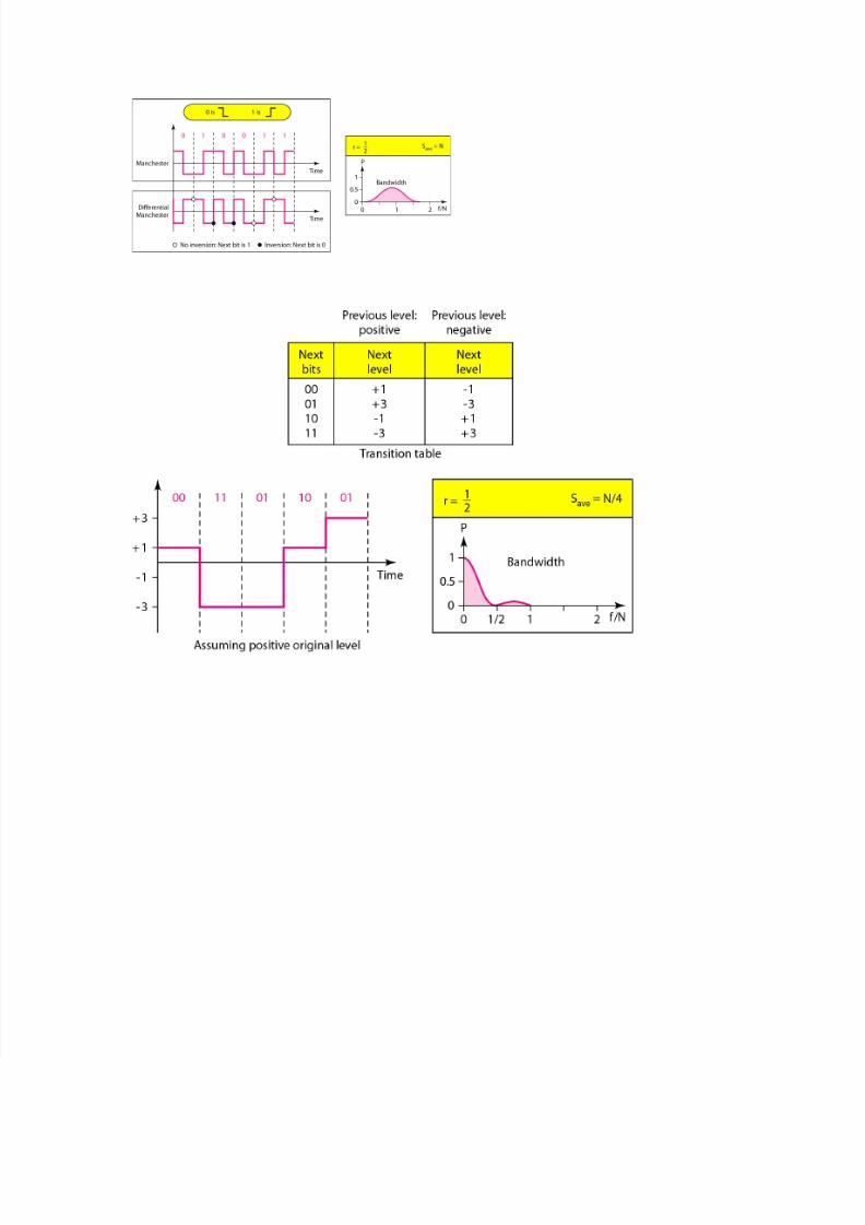
10.Explain different types line coding in data communication.
Sol:
Characteristics of coding:
Signal element; Data element
Data rate; Signal rate
Bandwidth
Baseline Wandering
DC component
Self-synchronizing
Built-in Error Detection
Immunity to Noise and Interference
Complexity
8/8/2019 Unit 1- 2 & 16 Marks
http://slidepdf.com/reader/full/unit-1-2-16-marks 25/26
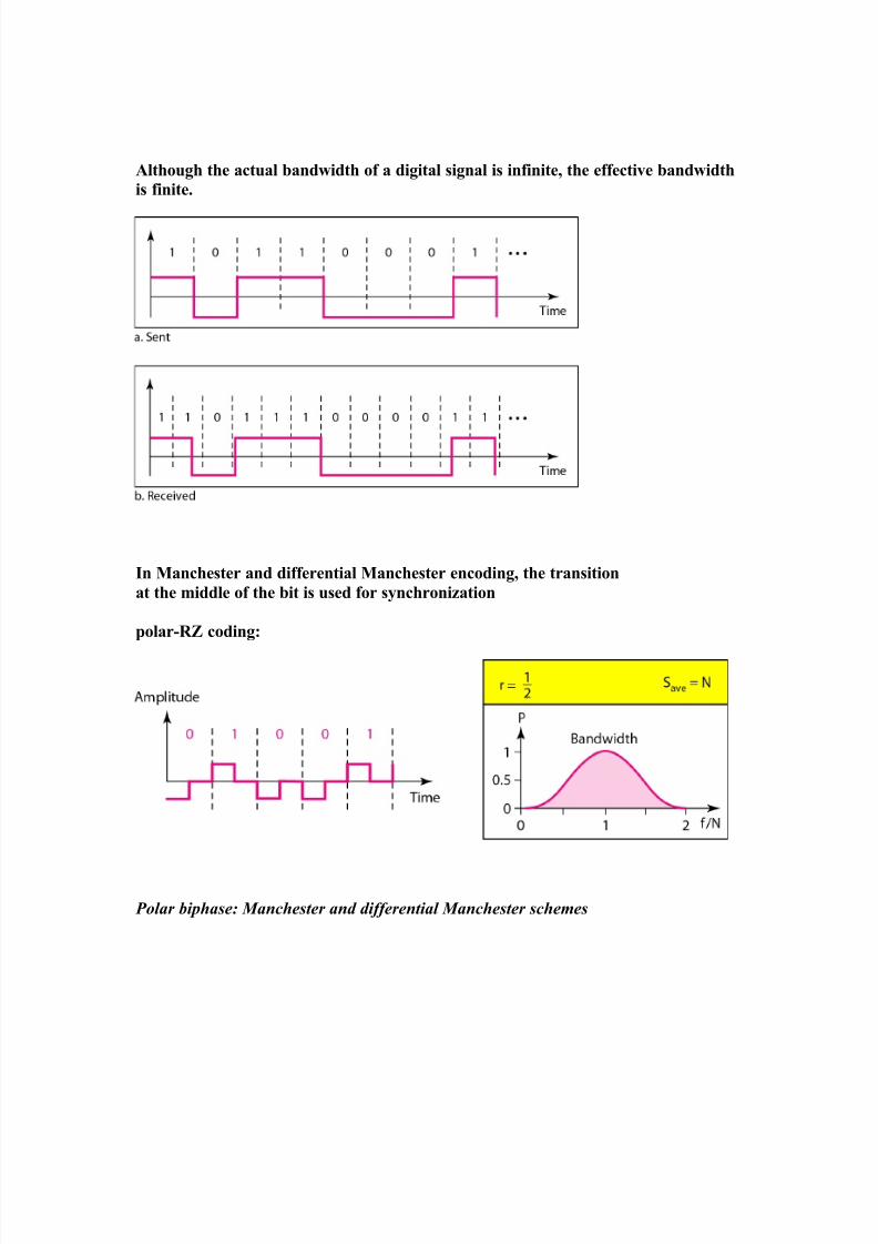
Although the actual bandwidth of a digital signal is infinite, the effective bandwidth
is finite.
In Manchester and differential Manchester encoding, the transition
at the middle of the bit is used for synchronization
polar-RZ coding:
Polar biphase: Manchester and differential Manchester schemes
8/8/2019 Unit 1- 2 & 16 Marks
http://slidepdf.com/reader/full/unit-1-2-16-marks 26/26