Embed Size (px)
Citation preview
7/29/2019 Unit 1 Piping
http://slidepdf.com/reader/full/unit-1-piping 1/21
UNITS IN THIS COURSE
UNIT 1 PIPING
UNIT 2 PIPE FITTINGS
UNIT 3 VALVES
TABLE OF CONTENTS
Para Page
1.0 COURSE OBJECTIVE 3
1.1 INTRODUCTION TO PIPING 4
1.2 PIPING SIZES 5
1.3 PIPE CODING 6
1.4 METAL PIPING 6
1.5 CORROSION 6
1.6 ELECTROCHEMICAL CORROSION 7
1.7 CORROSION PROTECTION 9
1.8 INTERNAL CORROSION 11
1.9 PIPELINE SAFETY 12
1.10 TUBING 13
1.11 USES OF TUBING 14
1.12 CONNECTING TUBING 15
1.13 PIPING INSULATION 17
1.14 PIPE SUPPORTS 22
1. 15 PIPERACKS 22
1. 16 PIPE HANGERS 23
1.0 COURSE OBJECTIVE
This course introduces the students to all the main pieces of static equipment on aplant site. Upon completion of the course the trainees will be able to describe and
M o d u l e N o .
7 : P i p i n g s y s t e m s
U n i t N o . 1
- P i p i n g
M o d u l e N o .
7 : P i p i n g s y s t e m s
U n i t N o .
1 - P i p i n g
M o d u l e N o .
7 : P i p i n g s y s t e m s
U n i t N o .
1 - P i p i n g
Page 1/24
7/29/2019 Unit 1 Piping
http://slidepdf.com/reader/full/unit-1-piping 2/21
discuss the following:
• Equipment Terminology.
• Theory of operation.
•Equipment construction.
• Hands on operation.
• Safety features.
• How the equipment is used in the overall process.
1.1 INTRODUCTION TO PIPING
The piping system is important to all plant operations. Because it looks very simple itis sometimes overlooked. However, if the piping system does not operate properly
a plant will shutdown.
It is very important that the trainee understands what a piping system does. Anoperator must ensure that the equipment is installed, maintained and operatedcorrectly.
Every plant has large and small piping systems. These systems have many differentuses in a plant. All fluids and gases in a plant are moved from place to place inpiping systems. The piping system includes pipe, pipe fittings to control thedirection of flow and valves to control the amount of flow.
The size of the pipe, pipe fittings and valves will vary depending on the different
processes. The material used to make up the piping system depends on thematerial being carried by the system.
The piping systems in a plant carry hot and cold water, crude oil, refined products,chemicals, gases and other fluids at many different temperatures, pressures, andflow rates.
All parts of a piping system must be properly inspected and maintained. The loss of a single piping system in one part of a plant may cause the shutdown of processesin the plant. It is very important that the trainee operator understands the operationand maintenance of the piping systems.
The main functions of a piping system are:
• To contain, control, transport and transfer liquids through the plant processes.
• To transport and sales and transfer finished products to the storage facilities
1.2 PIPING SIZES
Piping is manufactured (made) in standard lengths, diameters and wall thickness.The trainee must understand the correct pipe size to make sure the piping systemis safe.
There are four dimensions of a pipe which are used to indicate pipe size. These areshown in Figure 1-1
M o d u l e N o .
7 : P i p i n g s y s t e m s
U n i t N o .
1 - P i p i n g
M o d u l e N o .
7 : P i p i n g s y s t e m s
U n i t N o .
1 - P i p i n g
Page 2/24
7/29/2019 Unit 1 Piping
http://slidepdf.com/reader/full/unit-1-piping 3/21
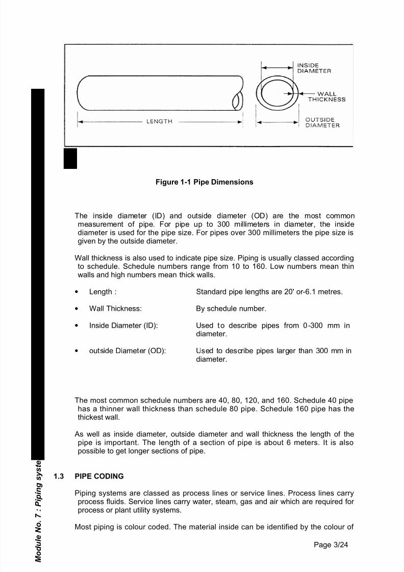
Figure 1-1 Pipe Dimensions
The inside diameter (ID) and outside diameter (OD) are the most commonmeasurement of pipe. For pipe up to 300 millimeters in diameter, the insidediameter is used for the pipe size. For pipes over 300 millimeters the pipe size isgiven by the outside diameter.
Wall thickness is also used to indicate pipe size. Piping is usually classed accordingto schedule. Schedule numbers range from 10 to 160. Low numbers mean thinwalls and high numbers mean thick walls.
• Length : Standard pipe lengths are 20' or-6.1 metres.
• Wall Thickness: By schedule number.
• Inside Diameter (ID): Used to describe pipes from 0-300 mm indiameter.
• outside Diameter (OD): Used to describe pipes larger than 300 mm indiameter.
The most common schedule numbers are 40, 80, 120, and 160. Schedule 40 pipehas a thinner wall thickness than schedule 80 pipe. Schedule 160 pipe has thethickest wall.
As well as inside diameter, outside diameter and wall thickness the length of thepipe is important. The length of a section of pipe is about 6 meters. It is alsopossible to get longer sections of pipe.
1.3 PIPE CODING
Piping systems are classed as process lines or service lines. Process lines carry
process fluids. Service lines carry water, steam, gas and air which are required for process or plant utility systems.
Most piping is colour coded. The material inside can be identified by the colour of
M o d u l e N o .
7 : P i p i n g s y s t e m s
U n i t N o .
1 - P i p i n g
Page 3/24
7/29/2019 Unit 1 Piping
http://slidepdf.com/reader/full/unit-1-piping 4/21
the pipe. The pipe may also have letters on it to identify the contents. For examplepipe which carries water for fire protection is usually painted red and is alsoidentified with white lettering.
Different companies may use different colour coding.
1.4 METAL PIPING
There are many different types of metal piping. Some of these are pure metals suchas aluminium or copper. Others are alloys such as stainless steel and carbon steel. An alloy is a metal made up of two or more metals which are melted together toform a new material.
Metal piping may be ferrous or non-ferrous. A ferrous metal is a metal whichcontains iron. Wrought iron, cast iron, and carbon steel are all examples of ferrousmetals.
Special metal pipe may be required for certain uses. Corrosive materials mayrequire special pipe. Highly corrosion resistant pipe is less common and moreexpensive then ferrous metal pipe.
1.5 CORROSION
Corrosion is the breakdown or deterioration of a substance because of a chemicalreaction with its environment. The substance does not necessarily have to be ametal to corrode. Wood, ceramics, plastic and other materials may also corrode. If a material corrodes its properties will change so it cannot do its job.
All metals and alloys can corrode. There are 105 known elements. About 80 of these are metals. Each one has different mechanical, chemical and physicalproperties. All metals corrode in different way and at different rates.
Some environments are more corrosive than others. There are always exceptionsbut it is generally true that:
• No corrosion will occur in a vacuum.• Salt water is more corrosive than fresh water.• Hot water is more corrosive than cold water.• Hot air is more corrosive than cold air.• Moist air is more corrosive than dry air.
• Polluted air is more corrosive than clean air.• Acids are more corrosive than bases.
1.6 ELECTROCHEMICAL CORROSION
Most of the corrosion which occurs in metals is electrochemical. This corrosion mayoccur on the inside or outside of a piece of metallic equipment.
M o d u l e N o .
7 : P i p i n g s y s t e m s
U n i t N o .
1 - P i p i n g
Page 4/24
7/29/2019 Unit 1 Piping
http://slidepdf.com/reader/full/unit-1-piping 5/21
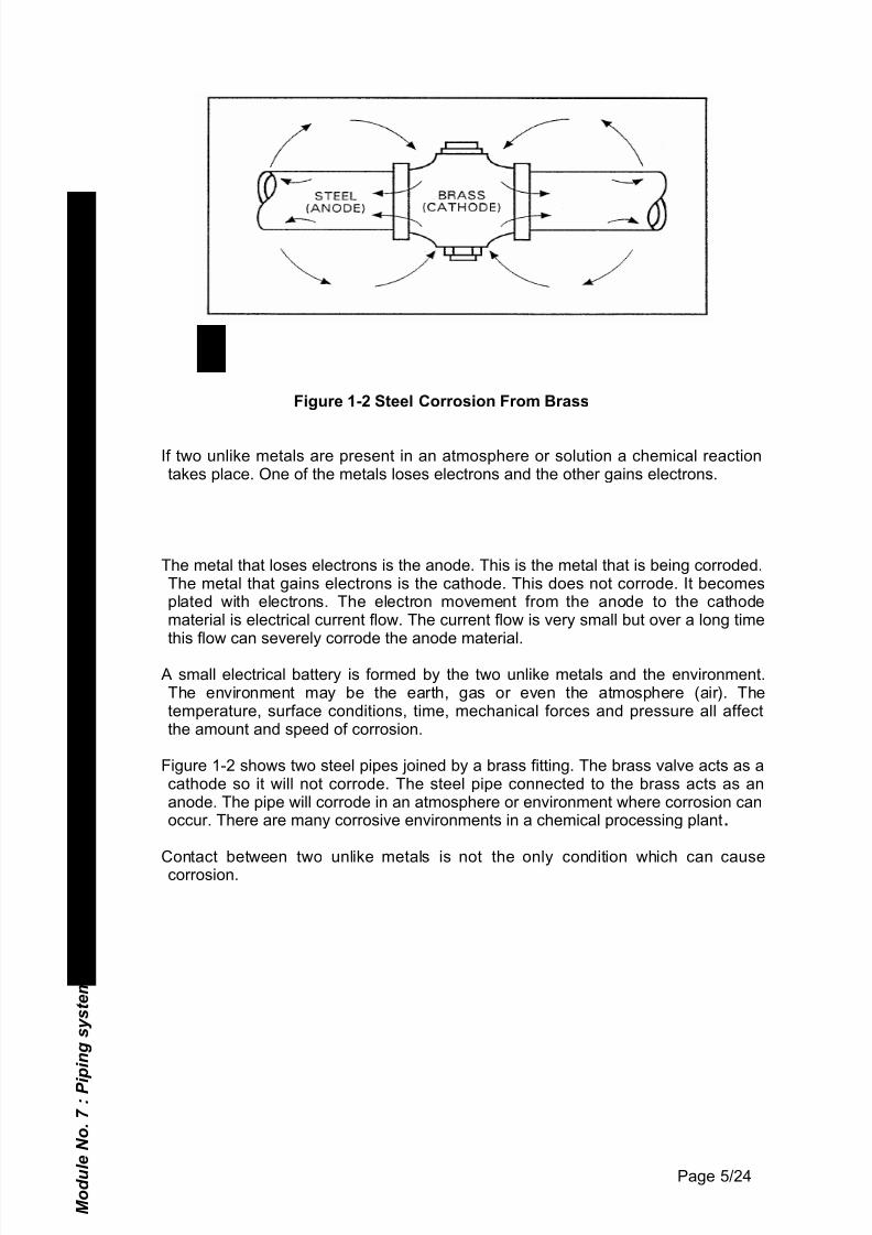
Figure 1-2 Steel Corrosion From Brass
If two unlike metals are present in an atmosphere or solution a chemical reactiontakes place. One of the metals loses electrons and the other gains electrons.
The metal that loses electrons is the anode. This is the metal that is being corroded.The metal that gains electrons is the cathode. This does not corrode. It becomesplated with electrons. The electron movement from the anode to the cathodematerial is electrical current flow. The current flow is very small but over a long timethis flow can severely corrode the anode material.
A small electrical battery is formed by the two unlike metals and the environment.The environment may be the earth, gas or even the atmosphere (air). Thetemperature, surface conditions, time, mechanical forces and pressure all affectthe amount and speed of corrosion.
Figure 1-2 shows two steel pipes joined by a brass fitting. The brass valve acts as acathode so it will not corrode. The steel pipe connected to the brass acts as ananode. The pipe will corrode in an atmosphere or environment where corrosion canoccur. There are many corrosive environments in a chemical processing plant.
Contact between two unlike metals is not the only condition which can causecorrosion.
M o d u l e N o .
7 : P i p i n g s y s t e m s
U n i t N o .
1 - P i p i n g
Page 5/24
7/29/2019 Unit 1 Piping
http://slidepdf.com/reader/full/unit-1-piping 6/21
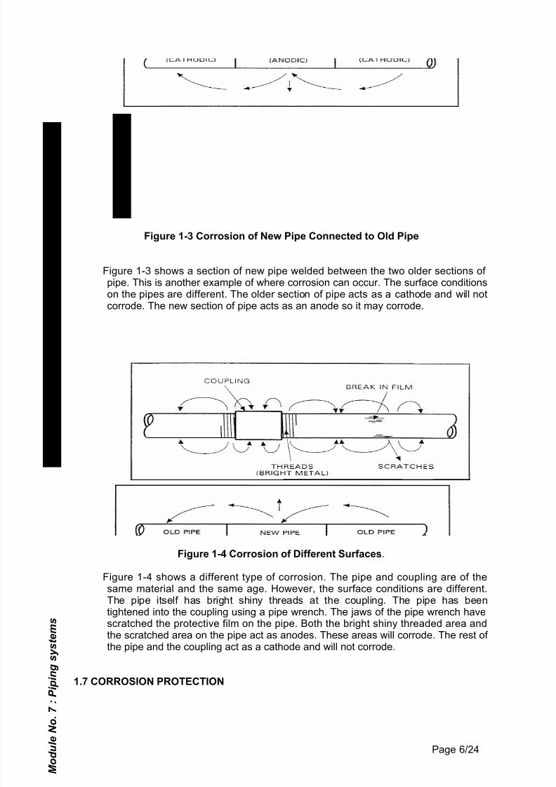
Figure 1-3 Corrosion of New Pipe Connected to Old Pipe
Figure 1-3 shows a section of new pipe welded between the two older sections of pipe. This is another example of where corrosion can occur. The surface conditionson the pipes are different. The older section of pipe acts as a cathode and will notcorrode. The new section of pipe acts as an anode so it may corrode.
Figure 1-4 Corrosion of Different Surfaces.
Figure 1-4 shows a different type of corrosion. The pipe and coupling are of thesame material and the same age. However, the surface conditions are different.The pipe itself has bright shiny threads at the coupling. The pipe has beentightened into the coupling using a pipe wrench. The jaws of the pipe wrench havescratched the protective film on the pipe. Both the bright shiny threaded area andthe scratched area on the pipe act as anodes. These areas will corrode. The rest of the pipe and the coupling act as a cathode and will not corrode.
1.7 CORROSION PROTECTION
M o d u l e N o .
7 : P i p i n g s y s t e m s
U n i t N o .
1 - P i p i n g
Page 6/24
7/29/2019 Unit 1 Piping
http://slidepdf.com/reader/full/unit-1-piping 7/21
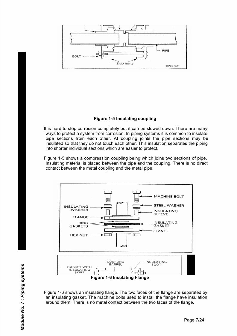
Figure 1-5 Insulating coupling
It is hard to stop corrosion completely but it can be slowed down. There are manyways to protect a system from corrosion. In piping systems it is common to insulatepipe sections from each other. At coupling joints the pipe sections may beinsulated so that they do not touch each other. This insulation separates the pipinginto shorter individual sections which are easier to protect.
Figure 1-5 shows a compression coupling being which joins two sections of pipe.Insulating material is placed between the pipe and the coupling. There is no directcontact between the metal coupling and the metal pipe.
Figure 1-6 Insulating Flange
Figure 1-6 shows an insulating flange. The two faces of the flange are separated byan insulating gasket. The machine bolts used to install the flange have insulationaround them. There is no metal contact between the two faces of the flange.
M o d u l e N o .
7 : P i p i n g s y s t e m s
U n i t N o .
1 - P i p i n g
Page 7/24
7/29/2019 Unit 1 Piping
http://slidepdf.com/reader/full/unit-1-piping 8/21
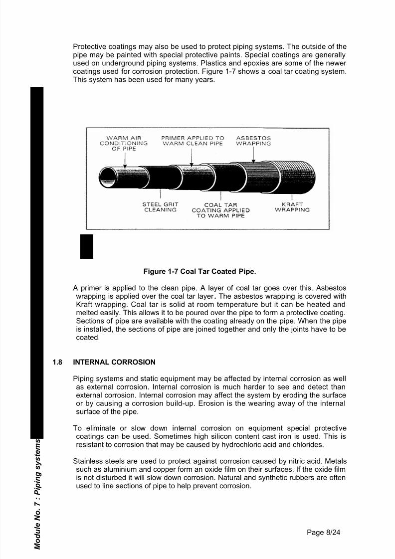
Protective coatings may also be used to protect piping systems. The outside of thepipe may be painted with special protective paints. Special coatings are generallyused on underground piping systems. Plastics and epoxies are some of the newer coatings used for corrosion protection. Figure 1-7 shows a coal tar coating system.This system has been used for many years.
Figure 1-7 Coal Tar Coated Pipe.
A primer is applied to the clean pipe. A layer of coal tar goes over this. Asbestos
wrapping is applied over the coal tar layer . The asbestos wrapping is covered withKraft wrapping. Coal tar is solid at room temperature but it can be heated andmelted easily. This allows it to be poured over the pipe to form a protective coating.Sections of pipe are available with the coating already on the pipe. When the pipeis installed, the sections of pipe are joined together and only the joints have to becoated.
1.8 INTERNAL CORROSION
Piping systems and static equipment may be affected by internal corrosion as wellas external corrosion. Internal corrosion is much harder to see and detect thanexternal corrosion. Internal corrosion may affect the system by eroding the surfaceor by causing a corrosion build-up. Erosion is the wearing away of the internalsurface of the pipe.
To eliminate or slow down internal corrosion on equipment special protectivecoatings can be used. Sometimes high silicon content cast iron is used. This isresistant to corrosion that may be caused by hydrochloric acid and chlorides.
Stainless steels are used to protect against corrosion caused by nitric acid. Metalssuch as aluminium and copper form an oxide film on their surfaces. If the oxide filmis not disturbed it will slow down corrosion. Natural and synthetic rubbers are oftenused to line sections of pipe to help prevent corrosion.
M o d u l e N o .
7 : P i p i n g s y s t e m s
U n i t N o .
1 - P i p i n g
Page 8/24
7/29/2019 Unit 1 Piping
http://slidepdf.com/reader/full/unit-1-piping 9/21
There are many different substances in the solutions carried In piping systems.Many of these substances may cause corrosion. Water in the plant may containoxygen, chloride or sulphate. These substances may cause corrosion. Inhibitorsare used to remove these corrosive substances.
Inhibitors are chemicals which slow down a chemical reaction. There may be a lot of salt in the water system. Sodium chromate is used as an inhibitor to slow downcorrosion caused by salt. If there is any hydrochloric acid in a steel pipe an inhibitor is needed.
Corrosion from liquids such as fuels, lubricants and other petroleum products isusually caused by small amounts of water. Both organic and inorganic inhibitorsare available to slow down this type of corrosion. The correct amount of inhibitor aswell as the correct method of application must be used. Sometimes the vessel ismade of extra thick metal to allow for corrosion.
Some chemicals may react with the surface of the pipe and cause a build up of
material. This deposit of material may become large enough to block the pipingsystem. Adding an inhibitor to the product in the piping system can loosen thismaterial and carry it away with the product in the piping system. However, thisloose scale may block the piping system. A piping system must be cleaned beforeany corrosion inhibitor is added to the piping system.
Shiny internal metal surfaces are more likely to be affected by corrosion thansurfaces which are covered with an oxide coating. A plant piping system should nothave sharp turns in it. Sharp turns can cause fluid turbulence. This fluid turbulencewears away any internal protective coating. The bare metal will then be exposed toboth erosion and corrosion.
Normally all metals and alloy can corrode. The amount and type of corrosion variesfrom metal to metal and system to system.
1.9 PIPELINE SAFETY
When a piping system is designed or operated the following safety factors must betaken into consideration:
• What temperature is the pipe designed to operate at.
•What pressure is the pipe designed to operate at.
• What other things may limit the pipe capacity i.e. pipe material, atmospheric
conditions, the material surrounding the pipe or what it is joined to.
Pipe Uses
Steel pipe is used for plumbing, heating, gas and air lines. Seamless carbon steelpipe is used in high temperature applications. Welded wrought iron pipe is used for condensate return lines in steam systems. Cast iron pipe is used for gas systems.Copper pipe is used where processing solutions may react with ferrous pipe.
Plastic pipe can be used to carry corrosive materials. It cannot be used at highpressures and temperatures. Thermoplastic piping has a temperature limit of 66 °
C. Thermosetting piping has a temperature limit of 121°C. M o d u l e N o .
7 : P i p i n g s y s t e m s
U n i t N o . 1
- P i p i n g
M o d u l e N o .
7 : P i p i n g s y s t e m s
U n i t N o .
1 - P i p i n g
Page 9/24
7/29/2019 Unit 1 Piping
http://slidepdf.com/reader/full/unit-1-piping 10/21
All piping has a special characteristics. Manufacturers information sheets and pipingtables give information on temperature, pressure and flow limits for different sizes,material and wall thickness. Never try to use a pipe for a purpose for which it is notdesigned.
Specifications for the piping system and the auxiliary equipment connected to the
piping system should be carefully checked. All safety precautions must befollowed.
1.10 TUBING
Tubing is pipe which has thin walls. It is made of metal or plastic. The type of tubingused will depend on the application it is being used for.
There are advantages and disadvantages in using tubing instead of piping. Tubingis very flexible. This means it can bend easily. This allows the tubing to beconnected to a device that vibrates without being damaged.
Tubing has the following advantages over normal pipework:
• Can be used in small areas / a large number of lines will fit in a small space.e.g., at the back of an instrument panel.
• Flexible, it can be bent around corners.
• Absorbs shock or vibration.
• Requires less fittings and less supports due to its light weight.
• Easy and quick to install.
• Quick repair so that a system can be back in service quickly.
• Very little flow restriction or turbulence.
Tubing has the following disadvantages over normal pipework:
• Only small inside diameter, so only small volumes can be handled.• Thin wall (Must be bendable).• Unions weaken the tubing when they are tightened down or crimped.• Tubing will crimp or break easily if hit or stepped on.
Cautions for Tubing Use:
• Bend correctly.
• Do not install where it will be hit or stepped on.
• Use the correct material for the job i.e.
∗ Always use same fitting material as tubing material.
∗ Use stainless steel in corrosive atmospheres.
∗ Use plastic for temporary installations only.
M o d u l e N o .
7 : P i p i n g s y s t e m s
U n i t N o .
1 - P i p i n g
Page 10/24
7/29/2019 Unit 1 Piping
http://slidepdf.com/reader/full/unit-1-piping 11/21
• When you join tubing make sure the ends are fully in the fitting beforetightening down.
1. 11 USES OF TUBING
Tubing is thin walled and is used in various areas in a plant. However, it is mainlyused for the following:
• Instrument air lines.
• Temporary lines.
• Hydraulic lines.
Copper tubing is used for plumbing, heating, cooling, gas, and steam lines. It can beburied underground as well as in the open air. Thicker walled copper tubing may be
used in high temperature applications.
Aluminium has the advantage that it becomes stronger at very low temperatures.For this reason it is used in cryogenic (low temperature) lines.
Stainless steel tubing is very strong. It can stand very high pressures. Stainlesssteel is used in high pressure hydraulic systems. Stainless steel tubing is also usedin cooling units, evaporators and fluid lines.
Stainless steel tubing is always used on offshore installations as it is resistant tocorrosion from the salt in the atmosphere. Low pressure pneumatic lines are madeof copper or plastic tubing.
Tubing can be bent quite easily. There are less connections are on a tubing systemthan on a piping system. Tubing usually has a small diameter so it can fit in spaceswhere it would be hard to install piping.
1.12 CONNECTING TUBING
Compression Fittings
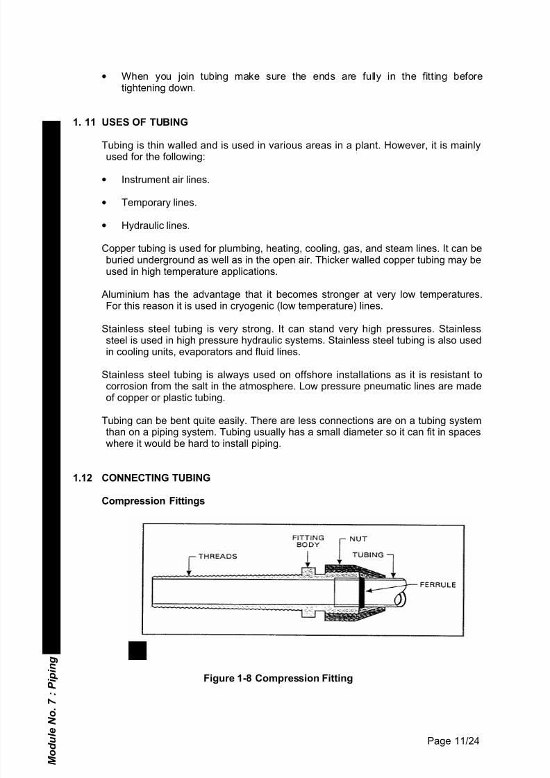
Figure 1-8 Compression Fitting
M o d u l e N o .
7 : P i p i n g s y s t e m s
U n i t N o .
1 - P i p i n g
Page 11/24
7/29/2019 Unit 1 Piping
http://slidepdf.com/reader/full/unit-1-piping 12/21
Figure 1-9 Compression Fitting
Tubing may be connected with compression fittings. Compression fittings areavailable in different sizes and styles. The tubing fits inside the compression fitting.By tightening the fitting nut a leak proof joint is formed. (See figures 1-8 and 1-9).
The tubing slips tightly into the fitting on one end. There is a ferrule or bushing thatfits around the tubing. The compression fitting is threaded at both ends. -The bodyof the fitting is held stationary while the nut is tightened. Tightening the nut causesthe ferrule to compress. This makes a leak proof joint between the tubing and thefitting.
There are also compression fittings for plastic and nylon tubing.
Flared Fittings
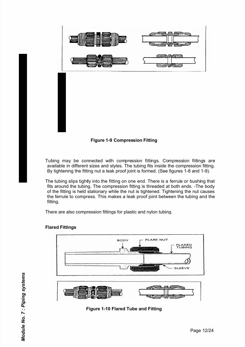
Figure 1-10 Flared Tube and Fitting
M o d u l e N o .
7 : P i p i n g s y s t e m s
U n i t N o .
1 - P i p i n g
Page 12/24
7/29/2019 Unit 1 Piping
http://slidepdf.com/reader/full/unit-1-piping 13/21
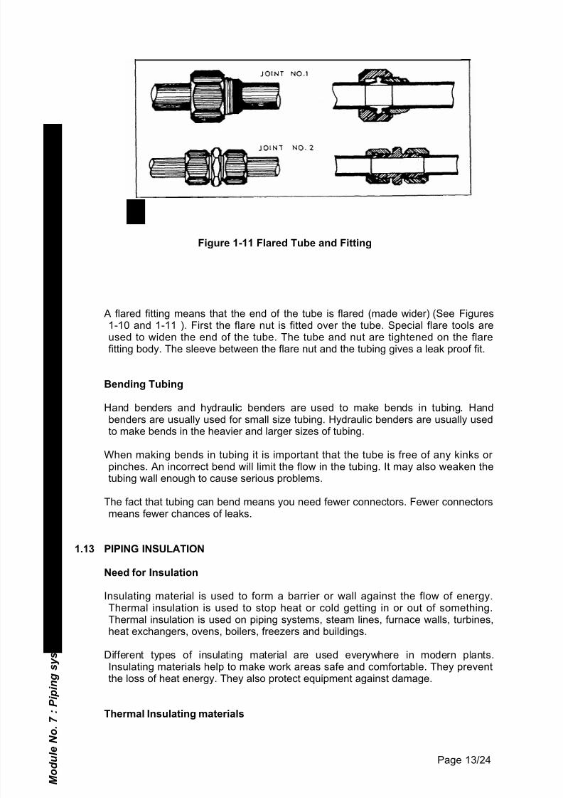
Figure 1-11 Flared Tube and Fitting
A flared fitting means that the end of the tube is flared (made wider) (See Figures1-10 and 1-11 ). First the flare nut is fitted over the tube. Special flare tools areused to widen the end of the tube. The tube and nut are tightened on the flarefitting body. The sleeve between the flare nut and the tubing gives a leak proof fit.
Bending Tubing
Hand benders and hydraulic benders are used to make bends in tubing. Hand
benders are usually used for small size tubing. Hydraulic benders are usually usedto make bends in the heavier and larger sizes of tubing.
When making bends in tubing it is important that the tube is free of any kinks or pinches. An incorrect bend will limit the flow in the tubing. It may also weaken thetubing wall enough to cause serious problems.
The fact that tubing can bend means you need fewer connectors. Fewer connectorsmeans fewer chances of leaks.
1.13 PIPING INSULATION
Need for Insulation
Insulating material is used to form a barrier or wall against the flow of energy.Thermal insulation is used to stop heat or cold getting in or out of something.Thermal insulation is used on piping systems, steam lines, furnace walls, turbines,heat exchangers, ovens, boilers, freezers and buildings.
Different types of insulating material are used everywhere in modern plants.Insulating materials help to make work areas safe and comfortable. They preventthe loss of heat energy. They also protect equipment against damage.
Thermal Insulating materials
M o d u l e N o .
7 : P i p i n g s y s t e m s
U n i t N o .
1 - P i p i n g
Page 13/24

7/29/2019 Unit 1 Piping
http://slidepdf.com/reader/full/unit-1-piping 14/21
Most metals are good conductors of heat. Heat transfers to metal. Metal will alsoradiate or transfer its heat to the atmosphere very easily. To contain heat or to stopheat from escaping thermal insulation must be used. Thermal insulation is also usedto prevent heat from entering a building during hot seasons of the year or to preventheat leaving a building during the cold season.
Page 14/24
7/29/2019 Unit 1 Piping
http://slidepdf.com/reader/full/unit-1-piping 15/21
Thermal insulation has a lot of uses because it can be used for temperaturesranging from below zero to as high as 1 450°C. The purpose of the insulation is tostop heat transfer. This saves money. Thermal insulation is also used to make theworkplace safer and more comfortable.
Most of the materials used as thermal insulation have a low density. This meansthat they have very little weight but they use a lot of space. These materials areloose and contain air spaces. The air spaces help the insulating properties of thematerial.
There are many types of thermal insulation. One of these is "loose fill". Loose fillinsulation is usually poured or packed into place. Some of the loose fill insulationmaterials used are:
• Asbestos Powder • Cork Granules• Powdered Gypsum
• Mineral Wool Pellets• Magnesia Powder and Light Weight Slags.
Some types of insulation are flexible. Flexible insulation can be fitted to curvedsurfaces. It comes in the form of blankets, sheets, and felts. it is installed bywrapping, nailing or by using glue. Flexible insulation is made from materials suchas asbestos felt, cotton, fibreglass, mineral wool, foam rubber and wood fibres.
Some types of insulation are rigid. They are available in blocks, boards, bricks,sheets and slabs. These rigid forms are often a mixture of different materials. Theymay contain internal bonders, air spaces and surface treatment. Rigid insulation ismade from materials such as
• Asbestos• Cork• Fire Clay• Mineral Wool• Foam Rubber
• Paper and Wood.
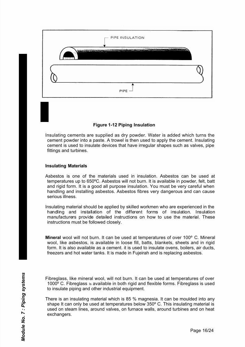
Insulation for piping is usually the same shape as the piping (pre formed). It comesin rigid half cylinders to fit specific sizes of piping and tubing. This rigid insulation isusually fitted to the piping with wire or metal band. A section of pipe insulation isshown in Figure 1-12.
M o d u l e
N o .
7 : P i p i n g s y s t e m s
U n i t N o .
1 -
P i p i n g
M o d u l e N o .
7 : P i p i n g s y s t e m s
U n i t N o .
1 - P i p i n g
Page 15/24
7/29/2019 Unit 1 Piping
http://slidepdf.com/reader/full/unit-1-piping 16/21
Figure 1-12 Piping Insulation
Insulating cements are supplied as dry powder. Water is added which turns thecement powder into a paste. A trowel is then used to apply the cement. Insulatingcement is used to insulate devices that have irregular shapes such as valves, pipefittings and turbines.
Insulating Materials
Asbestos is one of the materials used in insulation. Asbestos can be used at
temperatures up to 650ºC. Asbestos will not burn. It is available in powder, felt, battand rigid form. It is a good all purpose insulation. You must be very careful whenhandling and installing asbestos. Asbestos fibres very dangerous and can causeserious illness.
Insulating material should be applied by skilled workmen who are experienced in thehandling and installation of the different forms of insulation. Insulationmanufacturers provide detailed instructions on how to use the material. Theseinstructions must be followed closely.
Mineral wool will not burn. It can be used at temperatures of over 100º C. Mineral
wool, like asbestos, is available in loose fill, batts, blankets, sheets and in rigidform. It is also available as a cement. it is used to insulate ovens, boilers, air ducts,freezers and hot water tanks. It is made in Fujeirah and is replacing asbestos.
Fibreglass, like mineral wool, will not burn. It can be used at temperatures of over 1000º C. Fibreglass Is available in both rigid and flexible forms. Fibreglass is usedto insulate piping and other industrial equipment.
There is an insulating material which is 85 % magnesia. It can be moulded into any
shape It can only be used at temperatures below 350º C. This insulating material isused on steam lines, around valves, on furnace walls, around turbines and on heatexchangers.
M o d u l e N o .
7 : P i p i n g s y s t e m s
U n i t N o .
1 - P i p i n g
Page 16/24
7/29/2019 Unit 1 Piping
http://slidepdf.com/reader/full/unit-1-piping 17/21
There are also other materials that are used for insulation such as cork, foam rubber and foam glass. The type of material used as insulation depends on the situation.The insulating qualities of any installation depends on how carefully the insulatingmaterial is handled and installed.
In service areas the insulation may be in a place where it is easily damaged. It is
important to maintain the insulation regularly in these areas. If insulation material isdamaged it will not insulate properly
Cryogenic Applications
In recent years new insulating materials have been developed for cryogenicapplications (very cold conditions). These materials must be able to withstandtemperatures of minus 150ºC.
The most common insulating materials used for cryogenic applications include:
• Expanded foam.
• Gas filled powders with fibrous materials.
• Evacuated powders with fibrous materials.
• Multi-layer foil.
Insulating material which is used depends on:
• Cost of the materials
• Cost and ease of application.
• Insulating quality of the material.
• Weight of the material.
• Mechanical strength of the material.
Common expanded foam insulations include:
• Plastics
• Resins
• Rubber
• Silica.
• Glass.
The foam is usually pumped under pressure into the space to be insulated. As thefoam sets (dries) small spaces develop. These are filled with a gas which oftencomes from the chemical action of the foam. Helium or hydrogen are not very goodinsulating gases. Carbon dioxide is better.
One disadvantage of foams is that the expansion and contraction of the foam isquite different than that of metal. At cryogenic temperatures this difference is evengreater. Cracks can develop in the insulation. Heat can move through these cracks.
M o d u l e N o .
7 : P i p i n g s y s t e m s
U n i t N o .
1 - P i p i n g
Page 17/24
7/29/2019 Unit 1 Piping
http://slidepdf.com/reader/full/unit-1-piping 18/21
Foam is often used with other insulating materials. It is pumped into the openspaces left when Other types of insulation are applied.
Fibrous insulating materials have many open spaces. The movement of the gas inthese spaces can be slowed if the spaces are filled with powder. Gas that does not
move has better insulating abilities than that of moving gas. Fibrous material withpowder filler is usually a better insulation than foam.
Examples of fibrous insulation materials are
• Glass Fibre.
• Mineral Fibre.
• Perlite.
The powder is often finely ground cork.
Fibrous materials with powder insulate better if the gas is removed from the spaces.The extra cost of removing the gas must be calculated when you work out the costof this type of insulation.
The problem with powdered insulations is that the powder usually settles to thebottom. This can cause loss of heat.
Multilayer insulations are the most efficient insulating materials for cryogenic use.They are made of several layers of aluminium foil or aluminised mylar. There is afiller material between the layers. The filler material is usually made of glass fibre.
After the insulation is installed the air is removed from between the layers to createa vacuum. Multilayer insulation is lightweight. However, it is quite expensive anddifficult to install on irregular shapes.
1.14 PIPE SUPPORTS
Piping must be supported to keep it from sagging or moving. If pipework sags it putsstress on the connection fittings. This can cause leaks. The pipe support mustallow the pipe to expand and contract as the temperature changes.
There are many different types of pipe supports. Each one has its own application.
Pipe supports must be able to do the following:
• Support the weight of the pipework, valves, flanges, insulation and fluids insidethe pipe.
• Hold the pipework in a secure position.
• Allow the pipework to expand and contract due to high and low temperatures.Withstand vibration and fluid pulsation.
• Raise or lower the pipework as required by the process.
1. 15 PIPERACKS
M o d u l e N o .
7 : P i p i n g s y s t e m s
U n i t N o .
1 - P i p i n g
Page 18/24
7/29/2019 Unit 1 Piping
http://slidepdf.com/reader/full/unit-1-piping 19/21
Piperacks are made of steel I beam or angle iron. They can support a large number of pipes side by side. The rack will be shaped in a Tee T or a F1 upside down Ushape depending on the support required. The pipe rests on the surface of the rackand the weight of the pipe stops it from moving up and down. Pipe clamps aresometimes used to hold each pipe still in the pipe rack. The pipe rack can bemounted on the ground or overhead.
The pipes rest on shoes, saddle plates or pipe clamps. These pipe rests aredesigned to:
• Secure the pipe position.
• Allow for thermal expansion.
• Reduce pipe wear due to vibration.
The pipes may rest on a support or hang from it.
1.16 PIPE HANGERS
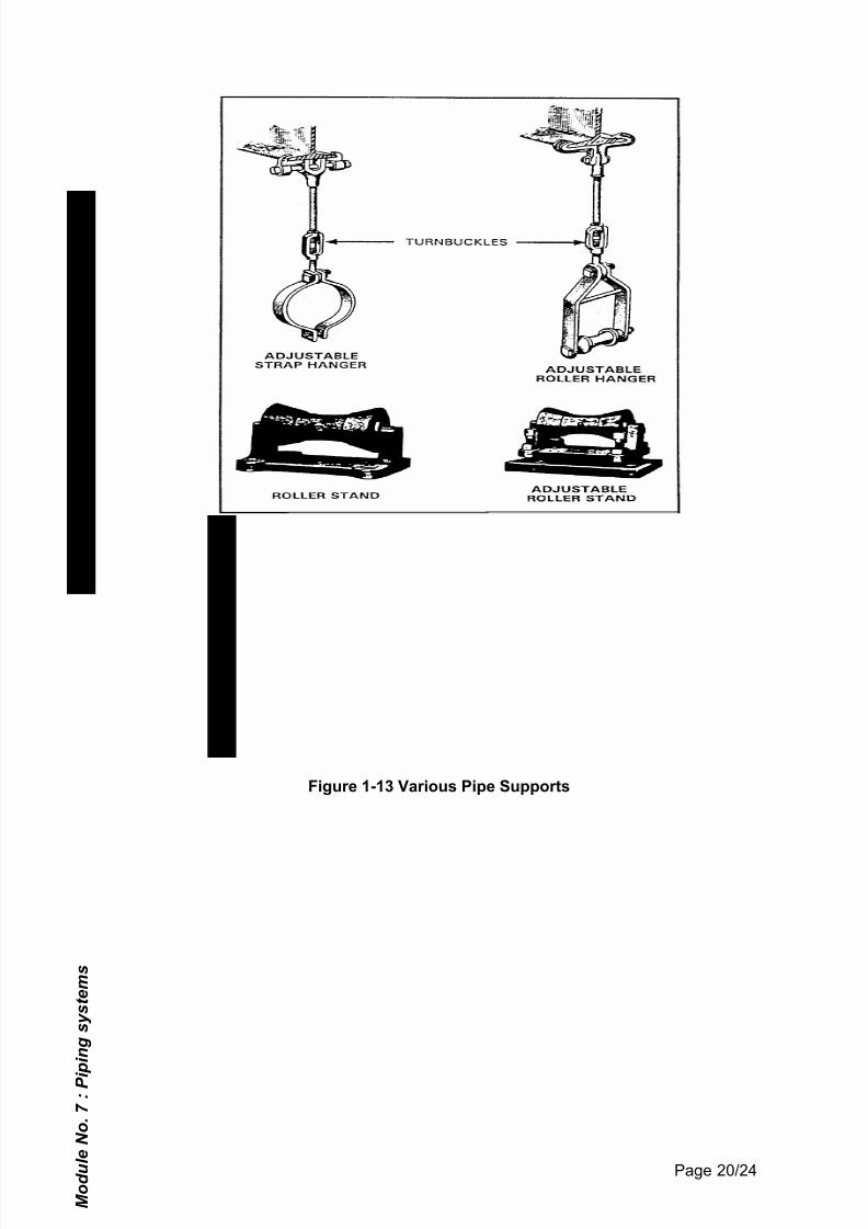
Some pipe hangers support pipes from steel beams or building support structures.They come in a number of different types designed to handle specific pipework.There are many different types of pipe hangers. The pipe supports on which thepipe rests are adjustable strap hanger, adjustable roller hanger, roller stand andadjustable roller stand (See Figure 1-13).
M o d u l e N o .
7 : P i p i n g s y s t e m s
U n i t N o .
1 - P i p i n g
Page 19/24
7/29/2019 Unit 1 Piping
http://slidepdf.com/reader/full/unit-1-piping 20/21
Figure 1-13 Various Pipe Supports
M o d u l e N o .
7 : P i p i n g s y s t e m s
U n i t N o .
1 - P i p i n g
Page 20/24
7/29/2019 Unit 1 Piping
http://slidepdf.com/reader/full/unit-1-piping 21/21
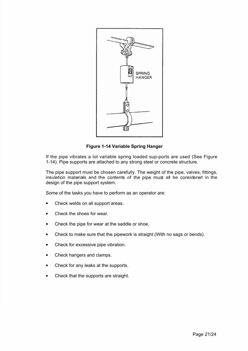
Figure 1-14 Variable Spring Hanger
If the pipe vibrates a lot variable spring loaded sup-ports are used (See Figure1-14). Pipe supports are attached to any strong steel or concrete structure.
The pipe support must be chosen carefully. The weight of the pipe, valves, fittings,insulation materials and the contents of the pipe must all be considered in the
design of the pipe support system.
Some of the tasks you have to perform as an operator are:
• Check welds on all support areas.
• Check the shoes for wear.
• Check the pipe for wear at the saddle or shoe.
• Check to make sure that the pipework is straight.(With no sags or bends).
•Check for excessive pipe vibration.
• Check hangers and clamps.
• Check for any leaks at the supports.
• Check that the supports are straight.


![Basic Piping[1]](https://img.pdfslide.net/doc/110x75/55cf9769550346d033917e4b/basic-piping1.jpg)
