Embed Size (px)
Citation preview
UNIT – 2. CONVEYANCE SYSTEM
Water supply -intake structures -Functions and drawings -Pipes and conduits for water-Pipe
materials -Hydraulics of flow in pipes -Transmission main design -Laying, jointing and
testing of pipes -Drawings appurtenances -Types and capacity of pumps -Selection of pumps
and pipe materials.
CONVEYANCE OF WATER
Drawing off water from the source of water called intakes.
Leading the water from intakes to the purification plants and then leading the
treated water to the consumer through distribution pipes.
INTAKE STRUCTURE FOR WATER SUPPLY
Intake structures are the construction, used for storing the water, from surface sources
(river, reservoir and lakes) and conveying it further to treatment plant.
An intake may be nearer to water sources such as river, lake, etc.
An intake is a structure which is constructed across the water source so as to permit
the safe withdrawal of water from the water source. The structure may be stone, brick,
RCC, or Concrete block masonry
Factors governing location of an intake
1. The location of intake structure should be nearer to the treatment plant, in order to
reduce the cost of conveyance water.
2. The location of the intake should be selected in a place, where there is the less
impurities presence.
3. The intake should be selected at a place from where the water can be taken during
driest season of the year also.
4. The intake location should have the possibility for future expansion and addition
without much increase in cost.
5. The intake should not be located at the downstream of the disposal point of
sewage.
6. It should be located in such a way that, it should not be affected by heavy flood
and the flood should not enter through the intake.
7. The intake should not be located near the navigation channels such as Harbour etc.
8. It should not be interference with river traffic if any.

DESIGN CONSIDERATIONS
Sl.No Criteria Design considerations
1 Factor of
safety
Against all external forces (Forces by floating
materials, pressure, heavy currents etc)
2 Self-weight To withstand water pressure
3 Safety If located near the navigation channels
4 Sub structure Foundation design against water pressure
5 Size Considerable ( Suitable with future expansions )
Type of intake structures
Simple submerged Intake
Intake Tower or River Intake Structures
Wet Intake Towers
Dry Intake Towers
Reservoir Intake
Variable depth lake water intake
Multi-level intake
Canal Intake Structures.
1. SIMPLE SUBMERGED INTAKE
A submerged intake structures consists of simple concrete block or a rock filled
timber crib supporting the starting end of the withdrawal pipe.
The withdrawal pipes are generally taken up to the sump well at shore from where
the water is lifted by pumps.
The intake opening is generally covered by screen so as to prevent the entry of
debris, ice etc., into the withdrawal pipe.
In case of lakes where silt tends to settle down, the intake opening is generally
kept about 2 to 2.5 m above the bottom of the lake and thus to avoid the entry of
silt and sediment.
Such intake structures should be placed in streams or intakes at a place where they
may not get buried under sediment and where there are deep water.

These are widely used intakes for small water supply projects drawing water from
streams and lakes having relatively little change in water surface elevation
throughout the year.
2. INTAKE TOWERS OR RIVER INTAKE STRUCTURES
Intake towers are generally used on large projects and on rivers or reservoirs where
there is large fluctuation of water level.

Gate controlled openings at various levels called ports are generally provided in these
concrete towers which may help in regulating the flow through the towers and permit
some selection of the quality of water to be withdrawn.
Accesses to these towers are generally provided for operating the gates, etc., by means
of a foot bridge from the tower up to the dam or up to the shore.
Types of Intake Towers (river)
Wet intake Towers
Dry Intake Towers
Wet Intake Tower
The wet intake is that type of intake tower in which the water level is practically the same
as the level of source of supply.
It is sometimes known as JACK Well and it is most commonly used.
It consists of a concrete circular shell filled with water up to the reservoir level and has a
vertical inside shaft which is connected to the withdrawal pipe.
Dry Intake Tower
The essential difference between a dry intake and wet intake is that in a wet intake the
water enters from the entry ports in to the intake and then it enters in to the conduit pipe
through separate gate controlled openings whereas in a dry intake water is directly drawn
in to the withdrawal pipe through the gate entry openings.
A dry intake will therefore have no water inside the intake if its gates are closed whereas
the wet intake will be full of water even if its gates are closed.

3. RESERVOIR INTAKES
When the flow in the river is not get guaranteed throught the year a dam is
constructed across it to store water in the reservoir so formed.
The reservoir intakes are practically similar to the river intake except that these
are located near the upstream face of the Dam where maximum depth of water is
available.
The access to intake is provided through a foot bridge.
The water level will be the same as the reservoir level.
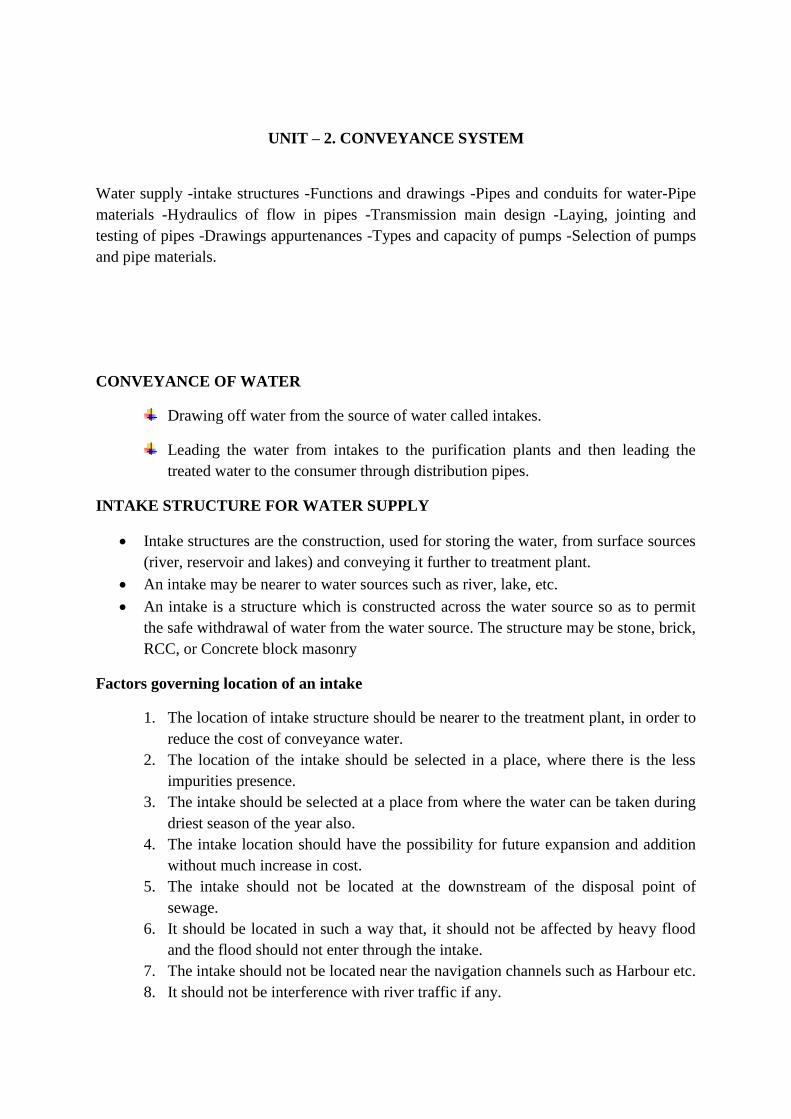
4. CANAL INTAKE
In canal intake structure, the intake well is generally located in the bank of the
canal and water enters the chamber through the inlet pipe.
The inlet pipe is covered with a fine screen.
The top of the screen is generally provided at minimum water level in the canal
and bottom is about 0.15 m above the canal bed to avoid entry of bed load.
The inlet end is of bell mouth shape with perforation of fine screen on its surface.
The flow velocity through the out let is generally 1.5 m/sec, and this helps in
determining the area and diameter at the withdrawal pipe.
The area of the coarse screen is designed by limiting the flow velocity to as low as
0.15m/sec.
The flow velocity through the bell mouth is limited to about 0.3 m/sec.
DESIGN OF INTAKES
Pipe is a circular closed conduit through which the water may flow either under
gravity or under pressure. They may be gravity conduit or may be pressure conduits.
Gravity conduit- Open channel, Flume & Aqueducts
Pressure conduit- Pipe
Discharge through pipe Q= A × V
o Where V is velocity in the pipe, A is cross sectional area of the pipe.
Diameter of the pipe is worked with the help of modified Darcy-Weisbach formula

Where, hf = head loss due to friction
f = co-efficient of friction
L = length of pipe
Q = Discharge through pipe
d = diameter of pipe.
OPEN CHANNEL
These are rarely used to transport the water from the source to treatment plant.
These can be effortlessly and cheaply constructed by cutting in elevated grounds
and banking in low grounds.
As water flows only due to gravitational force a uniform slope should be given.
FLUMES
The flumes are open channels, but the ground is supported by trestles etc.
The use of flumes is to transport the water across valleys and minor low lying
areas or over drains and other obstructions.
AQUEDUCTS
Aqueducts are channels either above ground, below ground or on the ground that
transport water from a lake or stream into a water treatment unit which may be
miles away.
The average velocity will be in the range between 1.0 to 1.5 m/sec.
Stresses in the Pipe
1. Stresses due to change of direction
2. Stresses due to internal water pressure
3. Stresses due to soil above the pipes
4. Stresses due to water hammer
5. Stresses due to yielding of soil below pipes and
6. Temperature stresses.
The final selection of material for the pipe is done by considering various factors
such as availability of funds, type of water to be conveyed, carrying capacity of pipes,
maintenance, cost and durability.

Various materials used for pipes
1. Asbestos cement pipes
2. Cast-iron Pipes
3. Cement concrete pipes
4. Copper pipes
5. Galvanised pipes
6. Lead pipes
7. Plastic pipes
8. Steel pipes
9. Steel pipes
10. Wood pipes
1. Asbestos cement pipe
Made from mixture of Asbestos fibre and cement.
Convey water under low pressure.
ADVANTAGES:-
Inside surface- Very smooth
Joining- Very good, flexible, easily
Light in weight, easy to handle & transport
Very suitable for distribution pipes of small size
DISADVANTAGES:-
Brittle; cannot withstand impact forces
Not durable
Cannot be laid in exposed places
Can be used only for very low pressure.
2. Cast iron pipes
Mainly used for conveyance of water.
Joined by bell and spigot (or) Expansion joint.
The spigot is of smaller diameter and is inserted to the larger diameter bell end.
Expansion Joint: Severe change of temperatures
A rubber gasket is inserted between the spigot and the bell end.
Flanged joint: Water at high pressure. At a wide flange will be provided which are
bolted together.
They are manufactured by pig-iron and given some suitable treatments
ADVANTAGES
The cost is moderate
Easy to join
Not subjected to corrosion

Strong & Durable
DISADVANTAGES
The breakage of these pipes is large.
Carrying capacity decreases with the increases in life
Not used for pressure greater than 0.7 N/mm^2
Heavier & Uneconomical- Size beyond 1200 mm dia.
3. Cement concrete pipes
Plain (or) Reinforced (or) Pre stressed pipes
Plain – 15 m , RCC – 75 m and High head – pre stressed.
Reinforcement in the form of links or hooks and longitudinal bars
Mould - Hume pipe (or) Spun concrete pipes
ADVANTAGES
Inside Surface – Very smooth
Maintenance cost is low
Pipes can be cast at site and can be transported.
Does not require expansion joint
No danger of rusting & incrustation
4. Copper pipes
Widely used for service connections
ADVANATGAES:-
Cheap, light in weight and easy to handle and transport.
Easy to join
DISADVANTAGES
Liable for incrustation & easily affected by acidic or alkaline water.
The useful life of pipe is pipe is short about 7 to 10 years.
5. Lead pipes
Not adopted for conveyance of water due to lead poisoning
It can be easily bent.
Apparatus required for alumn & chlorine discharge- can not water.
It can be bent due to hot water.
6. Plastic pipes
LDPE- Low Density Poly Ethylene Pipes- Flexible
Strong in resisting acids
PVC- Poly Vinyle Chloride Pipes three times as rigid as poly ethylene pipe.

ADVANTAGES
Freedom from damage due to thawing & freezing
Pipes are very cheap
Durable & Hydraulic resistant
Free from corrosion
Good electric insulator
Light in weight easy to bend
DISADVANTAGES
Co-efficient of expansion for plastic is high
Difficult to obtain the plastic pipes of uniform compositions
Less restraint to heat
Some type- impart to the taste of water.
7. Steel pipes
Mild steel is used for steel pipes
Joints – Riveted or Welded
Generally used for more than 1200 mm dia
Inside generally galvanized.
ADVANTAGES
Available in long length- No of joints less
Cheap & Best in cost
Durable & Strong
Flexible to some extent & laid easily on curves
Light in weight & easy to transport.
DISADVANTAGES
Maintenance cost is high
Rust attack due to alkali water
Require more time for repairing
Deform shapes under combined action of internal and external load.
8. Wood pipes
Usually prepared of staves or planks wood held together by steel bands.
Light in weight cannot bear higher pressure
Rarely adopted for conveyance of water.
9. Wrought Iron pipe
Light in weight can be easily cut threaded and worked.
Costly and Less durable. Not generally used in water conveyance system.

JOINTS IN PIPE
Pipe joints are the assemblies used to connect one pipe with other without any leakage or
other losses.
CLASSIFICATION
1. Based on the Rigidity & Flexibility
Rigid Joint
Semi Rigid Joint
Flexible Joint
2. Based on Functions & location
Spigot and Socket Joint
Expansion Joint
Flanged Joint
Screwed Joint
Rigid joints
Rigid Joints are those which admit no movement at all and comprise flanged,
welded and turned and bored joint.
Flanged joints require perfect alignment and close fittings and are frequently used
where a longitudinal thrust must be taken such as at the valves and meters.
The gasket used between the flanges of pipes shall be compressed fibre board or
natural or synthetic rubber.
Welded joints produce a continuous line of pipe with the advantage that interior
and exterior coatings can be made properly and are not subsequently disrupted by
the movement of joints.
Semi rigid joints
A semi rigid joint allows partial movement due to vibration etc.
The socketed end of the pipe should be kept against the flow of water and the
spigot end of the other pipe is inserted in to this socket .
A rope is then placed at the outer end of the socket and is made by tight fit by
applying wet clay leaving two holes for the escape of the entrapped air inside.
Flexible joints
Flexible joints are used where rigidity is undesirable such as filling of granular
and when two sections cannot be welded.
They comprise mainly mechanical and rubber ring joints which permit some
degree of deflection at each joint and are therefore able to withstand vibration and
movements.

In the rubber jointing special type of rubber gasket are used to connect cast iron
pipe which are cast with a special type of spigot.
Rubber joint is to be preferred to lead joining
Spigot & socket joint
This is mostly suitable for cast iron pipes
This type of joint is connected by inserting the spigot end of one pipe in to the
socket or bell end of the other.
The connecting procedure includes; wrapping of jute around the spigot before
inserting it in to the socket.
Then in the remaining space or gap between spigot and socket is filled by molten
lead.
Cooling time will be given for the solidification of molten lead.
The flexibility of this joint is less and need skilled labour.
Expansion joint
The main advantage of the expansion joints is its flexibility.
In some cases the pipes are laid over the ground and exposed to the atmosphere.
Due to thermal stresses the pipe will tend to expand and contract which ultimately
results in the formation of cracks in the external surface of the pipe and leak in the
joints.
In this type of joint the socket end is connected rigidly to an annular ring which
can freely over the spigot joint.
The provision of gasket will aid the pipe movement at the time of expansion due
to thermal stress.
Flanged joint
This type of joint mostly used for temporary pipe network.
The pipe has flanges at both the ends .This ends are connected by bolts and nut or
welding.
During the connection process a rubber gasket is placed between the two ends
which will prevent leakage.
This joint is commonly used in plumbing station boiler house etc.
But if this joint is used in steel pipe it will be better to connect by nuts and bolt
rather by other connection.
Screwed joint
The screwed joints are usually adopted when the pipe diameter is less
In this joint the ends of the pipes are threaded outside, while socket or coupling
has threads on both the ends of the pipe to join them.
For making water tight zinc paint or hemp yarn should be placed in the threads of
the pipe, before screwing socket over it.

LOSSES IN PIPE FLOW
1. Major Loss – Due to friction – Darcy’s formula
2. Minor Losses –Due to pipe arrangements and flow direction
k value will be
Sl.No Description K value
1 Sudden Contraction 0.3 - 0.5
2 Entrance 0.5
3 Elbow
1. 90 degree
2. 145 degree
3. 220 degree
0.50 to
1.00
0.40 to
0.75
0.25 to
0.50
4 Tee
1. 90 degree
2. Straight runner
3. Coupling
1.5
0.3
0.3
5 Gate valve (open) 0.3 to 0.4
6 Reducer and Increaser 0.5
7 Globe 10.00
8 Angle 5.00
9 Swing check 2.5
10 Venturimeter 0.3
11 Orificemeter 1.00
PIPE CORROSION
Loss of pipe materials due to the action of water
Metallic structure of the pipe is attacked and dissolved by water.
Action of water flowing through the pipe
Action of water logged in the soil above the pipe
Factors
1. Acidity, Alkalinity
2. Biological action
3. Chlorination
4. Electrical current
5. Oxygen
6. Mineral and organic constituents
gd
fLvh f
2
2
g
vkhm
2
2

Effects of pipe corrosion
1. Tuberculation- Formation of small projection inside the surface of the pipeline-
pipe carrying capacity is reduced.
2. Disintegration of pipeline – Demand heavy repairs
3. Effects on colour, taste & odour to the water
4. Affecting seriously the pipe connections
5. Water dangerous for drinking purposes.
Theories of pipe corrosion
1. Action of water motion
2. Bimetallic action
3. Biological action
4. Chemical reaction
5. Electrolysis
Prevention of pipe corrosion
1. Cathodic protection
2. Proper pipe materials
3. Protective lining
4. Treatment of water
PIPE APPURTENANCES
1. Sluice valve or Gate valve
2. Air valves
3. Reflux valves
4. Relief valves
5. Altitude valves
6. Scour valves
7. Fire Hydrants
8. Bib cocks
9. Stop cocks
10. Water meters
1. Sluice valve or Gate valve
It is used to control the flow of water and helpful in dividing the water mains into
the suitable sections.
They are generally placed at a distance of about 150mm-200mm and at all the
junction.
They are made of cast with brass mounting.
They are solid wedge type (or) double disk.

2. Air valves
They are normally called air relief valves.
To provide on exit of air, these valve is provided.
Located very close or above the hydraulic gradients.
It consists of a cast iron chamber, float, lever and poppet.

3. Reflux valves
These are also known as automatic cut off valves (or) safety valves.
They are located at every point along the water pipe where pressure is likely to be
maximum .
Where pressure of water exceeds a predetermined limit, the valve operate
automatically and it will save a particular section of water pipe before bursting the
pipe.
4. Relief valves
These are also known as automatic cut off valves or safety valves.
They are located at every point along the water pipe where pressure is likely to
maximum.
When pressure of water exceeds a predetermined limit the valve operates
automatically and it will save a particular section of water pipe before bursting the
pipe.

5. Altitude valves
They are mainly used on those lines which supply water to elevated tanks or stand
pipes.
They close automatically when the tank is full and open when the pressure on the
pump side is less than that on the tank side of the valve.
6. Scour valve
Scour valves (or) blow off (or) washout valves are ordinary sluice that located
either at the dead end or at lowest points in the main.
They are provided to blow off or remove sand and silt deposited in the pipeline.
They are operated manually.

7. Fire hydrants
A hydrant is an outlet provided in water pipe for tapping water mainly in case of a
fire.
Fire hydrant is used for fire fighting purposes.
They are placed at all junctions and so located that if a circle of about 60 to 90 m
drawn from any hydrant.
Type of Hydrants:-
1. Flush Hydrant
2. Post Hydrant
Requirements of a fire hydrant
1. It should be cheap
2. Easily detectable in case of fire
3. It can be easily connected with the hose motor pump
4. It should function properly and should not go out of order during operation.
5. It should permit undisturbed flow of water when being fully opened.
8. Bib cock
These are water taps which are attached at the end of water pipes and from which
the consumer obtain water.
It is operated from a handle.
They may also push type and they operate automatically.
They should be water tight; the leaky bib cocks are the source of waste water.

9. Stop cocks
These are small size sluice valves and they are installed in service pipes, serving
the bib cocks.
They operate on the same principles of sluice.
They are placed on water pipes leading to flushing tanks, wash basins, water tanks
etc.
10. Water meter
These are devices which are installed on the pipes to measure the quantity of water
flowing at a particular point along the pipe.
They usually installed at to supply water to industries, hotel, big institutions etc.

Types
1. Positive displacement type meter
2. Velocity meter
They should accurately measure discharge(2% tolerance)
They should easy to repair and maintenance
Should not too costly
They should be non corrosive.
WATER DISTRIBUTION SYSTEM
Lay out of Water Distribution System
1. Dead end system (or) Tree System
2. Grid- iron system (or) Reticulation System
3. Circular System (or) Ring System
4. Radial System.
1. Dead end or tree system
One main pipe line runs through the center of the populated area and sub-mains
takeoff from this to both sides.
The sub-mains divide into several branch lines from which service connections
are provided.

Advantages
i. The design calculation is simple and easy.
ii. A smaller number of cut-off valves are required and the operation and
maintenance cost is low.
iii. Pipe-laying is simple.
Disadvantages
i. The system is less successful in maintaining satisfactory pressure in the remote
areas and is therefore not favored in modern waterworks practice.
ii. One main pipeline provides the entire city, which is quite risky. Any defect,
damage or breakage at one point of this line will disrupt the supply of water
beyond that point, cutting off service to the whole area. This could be angerous,
especially if there is a fire.
iii. The head loss is relatively high, requiring larger pipe diameter, and/or larger
capacities for pumping units.
iv. Dead ends at line terminals might affect the quality of water by allowing
sedimentation and encouraging bacterial growth due to stagnation. Water hammer
could also cause burst of lines. A large number of scour valves are required at the
dead ends, which need to be opened periodically for the removal of stale water
and sediment.
v. The discharge available for firefighting in the streets will be limited due to high
head loss in areas with weak pressure.

2. Gridiron system
In Gridiron system the main supply line runs through the center of the area and
submains takeoff from this in perpendicular directions. The branch lines
interconnect the sub-mains.
This system is ideal for cities laid out in a rectangular plan resembling a grid iron.
The distinguishing feature of this system is that all of the pipes are interconnected
and there are no dead ends.
Water can reach a given point of withdrawal from several directions, which
permits more flexible operation, particularly when repairs are required.
Advantages
i. The free circulation of water, without any stagnation or sediment deposit,
minimizes the chances of pollution due to stagnation.
ii. Water is available at every point, with minimum loss of head, because of the
interconnections.
iii. Enough water is available at streets fire hydrants, as the hydrant will draw water
from the various branches lines
iv. During repairs, only a small area of distribution is affected.
Disadvantages
i. A large number of cut-off valves are required
ii. The system requires longer pipe lengths with larger diameters.
iii. The analysis of discharge, pressure and velocities in the pipes is difficult and
cumbersome.
iv. The cost of pipe-laying is higher

3. Circular or ring system
In circular or ring system, the supply main forms a ring around the distribution
area.
The branches are connected cross-wise to the mains and also to each other.
This system is most reliable for a town with well planned streets and roads.
The advantages and disadvantages of this system are the same as those of the grid
iron system. However, in case of fire, a larger quantity of water is available, and
the length of the distribution main is much larger.
4. Radial system
In a radial system, the whole area is divided into a number of distribution districts.
Each district has a centrally located distribution reservoir (elevated) from where
distribution pipes run radially towards the periphery of the distribution district.
This system provides swift service, without much loss of head.
The design calculations are much simpler.

LAYING JOINTING & TESTING OF PIPELINES
Transport
Pipes should be loaded at the works for transportation either by rail or by road.
No movements can be take place on vehicle during the transit
Off- Loading
It should be carried out by means of chain block with shear log or crane
Slings should be placed around the circumferential of the pipe and should not be
threaded through the pipe bore.
Hooks located at the ends of the pipes should not be used.
Stacking
Pipes can be directly placed on the ground free from rock and other projections.
Stacking in tyres is permissible provided timber bearer is placed between
succeeding tyres.
Stringing
It consists of placing of pipes on the ground in line ready for laying.
Trench Excavation
Trench should be sufficient width to provide a free working space.
Free working place – not less than 150 mm on either side.

Inspection and Repairs
1. Inspection of pipes before laying
Visually inspected for evidence of damage
Examination of joint surfaces which may damage during transit.
2. Repairing Damaged Pipes
Minor damages may be repairable at site.
Laying
Lowered in to the trench with tackle suitable for the weight of pipe
While lifting the position of the sling should be checked when the pipe is just
clear off to ensure proper balance.
Laying of pipe should be preferably proceed upgrade of a slope
Expansion joints shall be provided for buried line at maximum interval of 100m
but for exposed pipes shall not exceed 45 m.
When laying is not in progress the open end of the pipe line should be fitted with
temporary end closers.
The pipe buoyant in the event of the trench become flooded and any movements
of the pipes should be prevented either by partial refilling of the trench or by
temporary strutting.
Jointing
Basic requirements of joining of the pipelines are
Cleanliness of all the parts particularly joint surfaces
Correct location of components
Centralization of spigot within the socket
Provision of the correct gap between the end of the spigot and the back of the socket
to ensure flexibility at each joints
Any lubrication used shall be approved as composition and method of application
The section of the pipeline laid and jointed immediately to protect it from weather
effects
A minimum cover of 100 mm is considered adequate
A polythene sheet also is used to cover the joints to prevent evaporation of water.
A small change in the direction may be setting out adjacent pipe at a slight angle to
one another.
Testing
All pipe lines should be tested before come in service.
Hydrostatic Test

Filling the pipe line with water and raising pressure to selected limit.
Draw graph between the quantity of water added and the time.
Site Test Pressure
Absorption of water by the pipe material under selected pressure
The important factors of considerations are
The density of the pipe material.
Amount of surplus water present in the pipe at the commencement of test.
The amount and quality of cement matrix in case of concrete pipe
Thickness of the pipe unit under test
The pressure applied
The duration of the test.
The field test pressure to be imposed should not be less than the greatest of the following
1.5 times the maximum sustain operating pressure
1.5 times the maximum pipe line static pressure
Sum of maximum sustained pressure and maximum surge pressure
Sum of maximum pipeline static pressure and maximum surcharge pressure.
The pressure should be applied and maintain for at least four hours, if there is no
leakage then the pipe line is ok
Allowable leakage
Leak detection
Visual inspection of each joints if not covered by back fill
Use of a bar probe to detect signs of water in the vicinity of joints if backfilled
Aural inspection using a stethoscope or listening stick in contact with pipeline
Use of an electronic listening device which detect and amplifies the sound of
escaping water
Injection of dye into the test water
Introduction of Nitrous oxide solution into the test water using IR- gas
concentration; escaped through the leaks.

Pumps for water supply
Centrifugal pump
Reciprocating pump
Submergible pump
Air lift pumps
Rotary pumps
CENTRIFUGAL PUMP

RECIPROCATING PUMP
AIR LIFT PUMPS


![ASME B36[1].10M Welded and Seamless Wrought Steel Pipe](https://img.pdfslide.net/doc/110x75/55cf96a6550346d0338ce1fb/asme-b36110m-welded-and-seamless-wrought-steel-pipe.jpg)