Embed Size (px)
Citation preview
TRADE OFPipefitting
PHASE 2
Module 2
Thermal Processes
UNIT: 6
Oxy-Fuel Cutting

Produced by
In cooperation with subject matter expert:
Finbar Smith
© SOLAS 2014
Oxy-Fuel Cutting
Revision 2.0 September 2014
Module 2– Unit 6
Table of ContentsUnit Objective......................................................................1Learning Outcome...............................................................21.0 Oxy-Fuel Cutting for Pipefitting................................3
1.1 Oxy-Fuel Cutting.......................................................31.2 The Oxy-Fuel Cutting Process...................................31.3 Identification of Issues with Flame Cut Edges.........41.4 The Fuel Gas Used in Oxy-Fuel Cutting....................5
2.0 Oxy-Fuel Cutting Equipment....................................62.1 Flame Cutting Equipment.........................................62.2 Cutting Torch............................................................62.3 Cutting Nozzles.........................................................62.4 Cutting Devices to Aid Cutting Movement...............72.5 Profile Machine for Automated Cutting
..................................................................................10
3.0 Oxy-Fuel Cutting Techniques..................................................................................11
3.1 Lighting and Adjusting the Cutting Flame..................................................................................11
3.2 General Cutting Techniques..................................................................................11
3.3 Cutting Techniques for Thick Material..................................................................................12
3.4 Cutting Techniques for Painted or Galvanised Material..................................................................................12
3.5 Cutting Techniques for Stack Cutting..................................................................................12
4.0 Safety Precautions for Oxy-Acetylene Welding..................................................................................13
4.1 Safety Check..................................................................................13
4.2 Nozzle Cleaning..................................................................................14
5.0 Assembling Oxy-Fuel Cutting Equipment..................................................................................15
Industrial Insulation Phase 2
Oxy-Fuel Cutting
Revision 2.0 September 2014
Module 2– Unit 6
5.1 Step by Step Instruction..................................................................................15
5.2 Setting Gas Pressure for Oxy-Fuel Cutting..................................................................................16
5.3 Shut Down Procedure..................................................................................16
6.0 Effects of Heat on Mild Steel..................................................................................17
6.1 Oxy-Fuel Cutting Process..................................................................................17
6.1 Flame Hardening..................................................................................18
Exercises..................................................................................19
Additional Resources..................................................................................19
Industrial Insulation Phase 2
Oxy-Fuel Cutting
Revision 2.0 September 2014
Module 2 – Unit 6
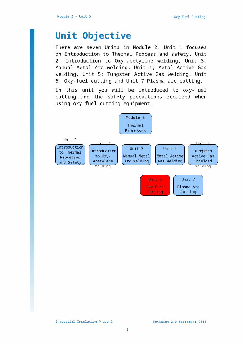
Unit ObjectiveThere are seven Units in Module 2. Unit 1 focuses on Introduction to Thermal Process and safety, Unit 2; Introduction to Oxy-acetylene welding, Unit 3; Manual Metal Arc welding, Unit 4; Metal Active Gas welding, Unit 5; Tungsten Active Gas welding, Unit 6; Oxy-fuel cutting and Unit 7 Plasma arc cutting.In this unit you will be introduced to oxy-fuel cutting and the safety precautions required when using oxy-fuel cutting equipment.
Industrial Insulation Phase 2
1
Module 2Thermal
Processes
Unit 1
Introduction to Thermal
Processes and Safety
Unit 2
Introduction to Oxy-
Acetylene Welding
Unit 3
Manual Metal Arc Welding
Unit 5
Tungsten Active Gas Shielded Welding
Unit 4
Metal Active Gas Welding
Unit 6
Oxy-Fuel Cutting
Unit 7
Plasma Arc Cutting
Oxy-Fuel Cutting
Revision 2.0 September 2014
Module 2 – Unit 6
Learning OutcomeBy the end of this unit each apprentice will be able to:
Describe the oxy-fuel cutting process and how it is applied in the pipefitting trade.
Identify the different fuel gases, equipment and PPE used for oxy-fuel cutting
State the safety precautions required when using oxy-fuel equipment
Light up and adjust gas pressures to correct setting and cut a selection of different thicknesses of metal pieces using oxyacetylene cutting equipment
State the effects of heat on mild steel when cutting with oxy-fuel cutting equipment
Industrial Insulation Phase 2
2
Oxy-Fuel Cutting
Revision 2.0 September 2014
Module 2 – Unit 6
1.0Oxy-Fuel Cutting for Pipefitting
Key Learning Points Identify the operations involved in the oxy-fuel
cutting process Key points for a desirable flame cut edge
1.1 Oxy-Fuel CuttingOf all the methods used for material removal in the fabrication industry, the flame-cutting process plays a prominent part in the preparation of mild-steel plate material for welded fabrications. It is readily applicable to very large thicknesses of material and allows a multiplicity of shapes or contours to be cut - two points which restrict the use of guillotines.It is faster than machining operations, which is an important advantage in connection with plate edge preparations for welded joints.Most metals oxidise. The rate of oxidation in air depends upon the type of material and the temperature. The properties of the oxides formed are different from that of the parent metal.Oxygen combining with a metal at a slow rate, as in the case of the rusting of iron, is referred to as 'OXIDATION', whereas if the formation of the oxide is very rapid, it is referred to as 'COMBUSTION' or 'BURNING'.Generally, a rise in temperature of the metal has the effect of accelerating the rate of oxidation. In the case of mild steel when heated at a temperature of 890°C (bright cherry red), complete combustion takes place if it is in any atmosphere of pure oxygen, and a magnetic oxide of iron is formed.
1.2 The Oxy-Fuel Cutting ProcessBecause cutting is essentially an oxidising process, little or no steel is melted. The kerf (the width of cut) should therefore be quite clean, and the top and bottom edges should be square. On examining melted oxides after cutting, it has been found that they contain up to 30 per cent unmelted steel, which has been scoured from the sides of the cut by the high-pressure oxygen stream. This scouring can be seen if the sides of the kerf are inspected, because drag lines will be faintly etched on the faces of the metal.
Industrial Insulation Phase 2
3
Oxy-Fuel Cutting
Revision 2.0 September 2014
Module 2 – Unit 6
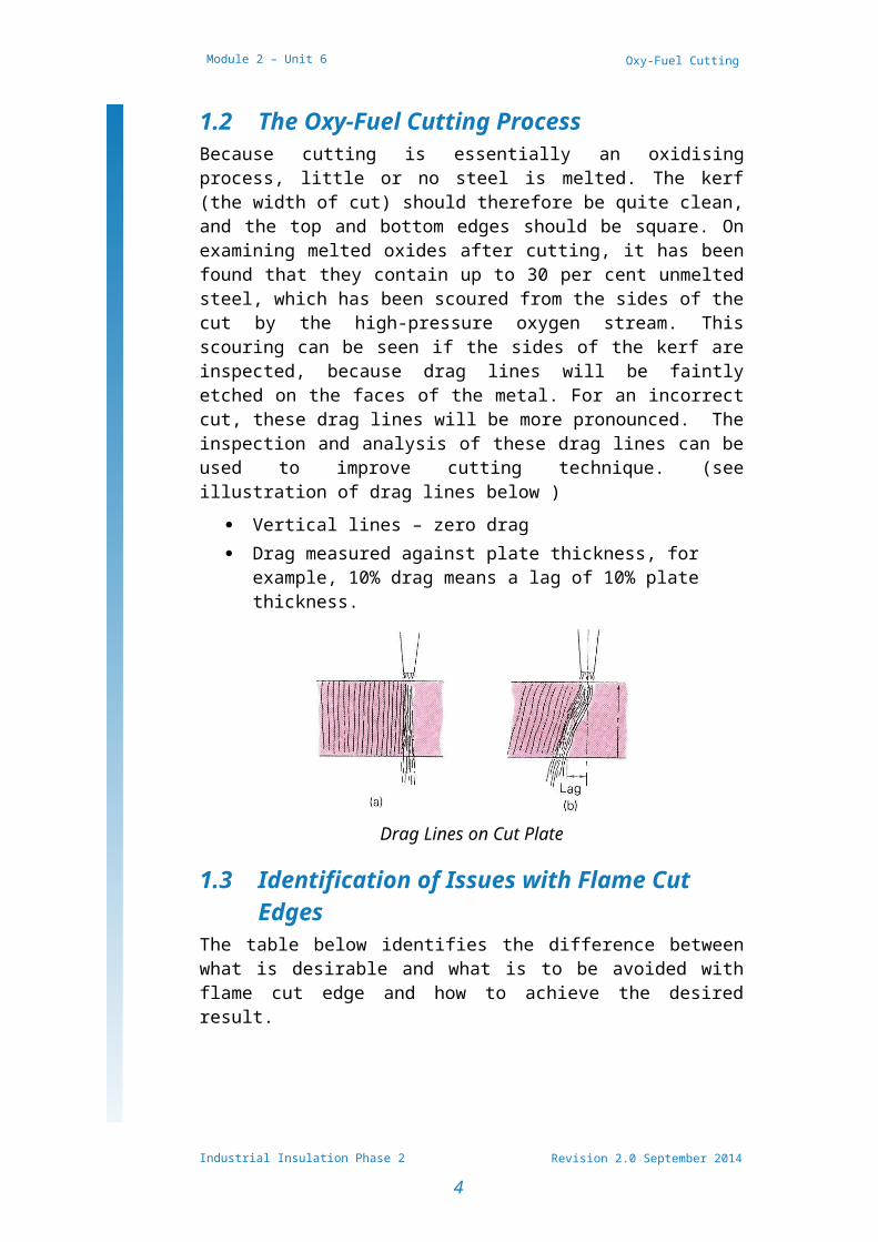
For an incorrect cut, these drag lines will be more pronounced. The inspection and analysis of these drag lines can be used to improve cutting technique. (see illustration of drag lines below )
Vertical lines – zero drag Drag measured against plate thickness, for example,
10% drag means a lag of 10% plate thickness.
Drag Lines on Cut Plate
1.3 Identification of Issues with Flame Cut Edges
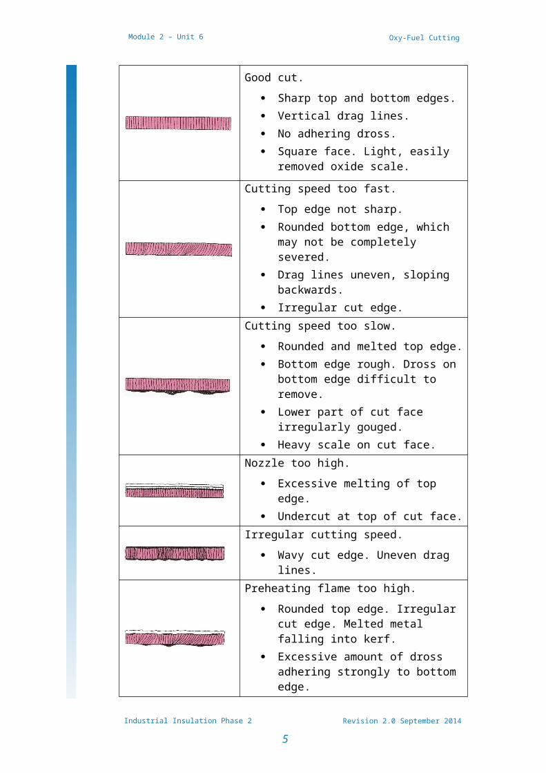
The table below identifies the difference between what is desirable and what is to be avoided with flame cut edge and how to achieve the desired result.
Good cut. Sharp top and bottom edges. Vertical drag lines. No adhering dross. Square face. Light, easily
removed oxide scale.
Cutting speed too fast. Top edge not sharp. Rounded bottom edge, which
may not be completely severed. Drag lines uneven, sloping
backwards. Irregular cut edge.
Industrial Insulation Phase 2
4
Oxy-Fuel Cutting
Revision 2.0 September 2014
Module 2 – Unit 6
Cutting speed too slow. Rounded and melted top edge. Bottom edge rough. Dross on
bottom edge difficult to remove. Lower part of cut face
irregularly gouged. Heavy scale on cut face.
Nozzle too high. Excessive melting of top edge. Undercut at top of cut face.
Irregular cutting speed. Wavy cut edge. Uneven drag
lines.Preheating flame too high.
Rounded top edge. Irregular cut edge. Melted metal falling into kerf.
Excessive amount of dross adhering strongly to bottom edge.
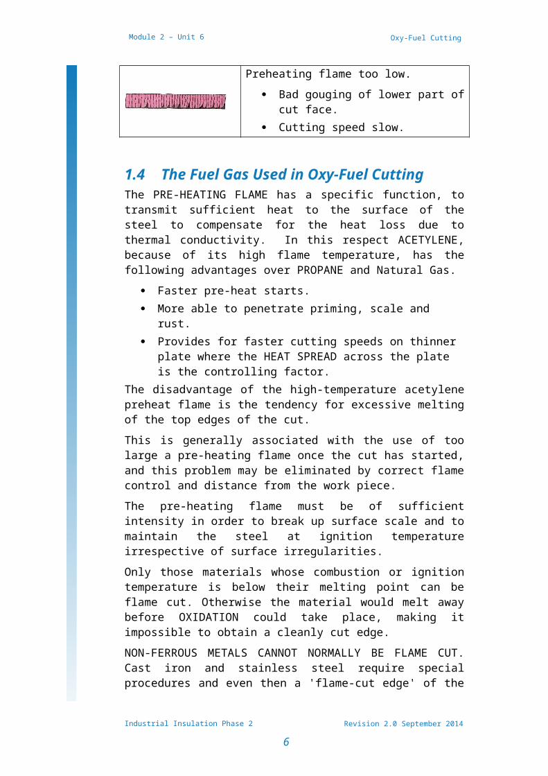
Preheating flame too low. Bad gouging of lower part of cut
face. Cutting speed slow.
1.4 The Fuel Gas Used in Oxy-Fuel Cutting
The PRE-HEATING FLAME has a specific function, to transmit sufficient heat to the surface of the steel to compensate for the heat loss due to thermal conductivity. In this respect ACETYLENE, because of its high flame temperature, has the following advantages over PROPANE and Natural Gas.
Faster pre-heat starts. More able to penetrate priming, scale and rust. Provides for faster cutting speeds on thinner plate
where the HEAT SPREAD across the plate is the controlling factor.
The disadvantage of the high-temperature acetylene preheat flame is the tendency for excessive melting of the top edges of the cut.
Industrial Insulation Phase 2
5
Oxy-Fuel Cutting
Revision 2.0 September 2014
Module 2 – Unit 6
This is generally associated with the use of too large a pre-heating flame once the cut has started, and this problem may be eliminated by correct flame control and distance from the work piece.The pre-heating flame must be of sufficient intensity in order to break up surface scale and to maintain the steel at ignition temperature irrespective of surface irregularities.Only those materials whose combustion or ignition temperature is below their melting point can be flame cut. Otherwise the material would melt away before OXIDATION could take place, making it impossible to obtain a cleanly cut edge.NON-FERROUS METALS CANNOT NORMALLY BE FLAME CUT. Cast iron and stainless steel require special procedures and even then a 'flame-cut edge' of the same quality as with plain carbon steel is difficult to obtain.
Industrial Insulation Phase 2
6
Oxy-Fuel Cutting
Revision 2.0 September 2014
Module 2 – Unit 6
2.0Oxy-Fuel Cutting Equipment
Key Learning Points Identify the component parts of oxy-fuel cutting
equipment Identify the differences in oxy-fuel cutting nozzles Identify automated oxy-fuel cutting equipment
2.1 Flame Cutting EquipmentSince the oxygen-cutting process involves directing a high-pressure jet of oxygen continuously on to an area of steel that has been previously heated to ignition temperature, the basic equipment combines a preheating flame and a pure oxygen source. Both these requirements are provided by a specially designed cutting torch and nozzle combination which is connected to a FUEL GAS and an OXYGEN supply, in the same manner as a gas-welding torch. The cutting torch and nozzle combinations are of' varying design, depending on the specific type of cutting to be employed. The equipment required for gas welding has already been described and oxy-gas cutting equipment is basically similar except for the following items:
2.2 Cutting Torch
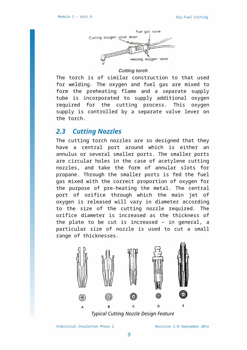
The torch is of similar construction to that used for welding. The oxygen and fuel gas are mixed to form the preheating flame and a separate supply tube is incorporated to supply additional oxygen required for the cutting process. This oxygen supply is controlled by a separate valve lever on the torch.
2.3 Cutting NozzlesThe cutting torch nozzles are so designed that they have a central port around which is either an annulus or several smaller ports. The smaller ports are circular holes in the case of acetylene cutting nozzles, and take the form of
Industrial Insulation Phase 2
7
Oxy-Fuel Cutting
Revision 2.0 September 2014
Module 2 – Unit 6
annular slots for propane. Through the smaller ports is fed the fuel gas mixed with the correct proportion of oxygen for the purpose of pre-heating the metal. The central port of orifice through which the main jet of oxygen is released will vary in diameter according to the size of the cutting nozzle required. The orifice diameter is increased as the thickness of the plate to be cut is increased – in general, a particular size of nozzle is used to cut a small range of thicknesses.
Typical Cutting Nozzle Design FeatureA One-piece ACETYLENE cutting nozzle – parallel bore, 3-9 pre-heat holes, no skirt.B Two-piece ACETYLENE cutting nozzle – venturi bore, pre-heat annulus, no skirt.C Two-piece NATURAL GAS nozzle-venturi bore, pre-heat flutes, long skirt.
D Two-piece PROPANE nozzle – parallel bore, pre-heat slots, long skirt.E Two-piece PROPANE nozzle – parallel bore, pre-heat flutes, long skirt, oxygen curtain.
2.4 Cutting Devices to Aid Cutting Movement
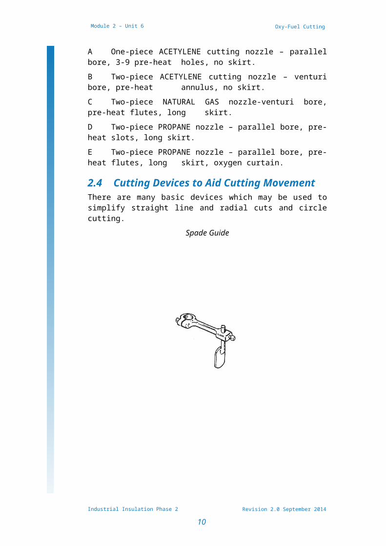
There are many basic devices which may be used to simplify straight line and radial cuts and circle cutting.
Spade Guide
Industrial Insulation Phase 2
8
Oxy-Fuel Cutting
Revision 2.0 September 2014
Module 2 – Unit 6
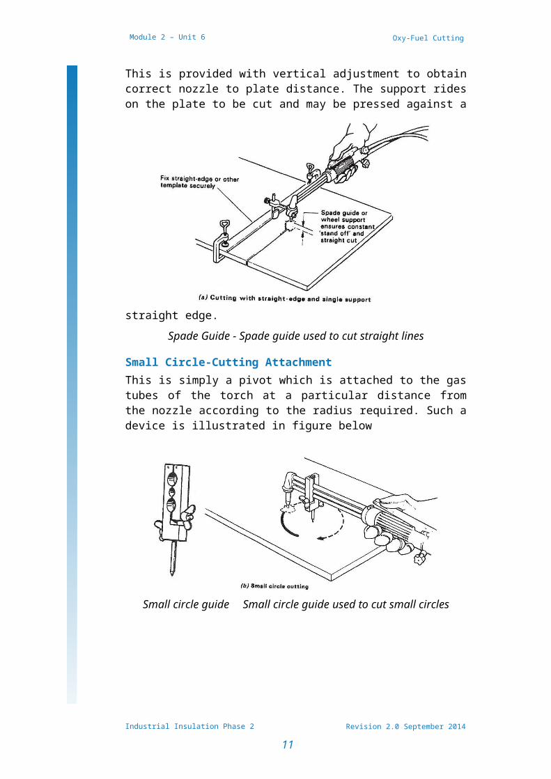
This is provided with vertical adjustment to obtain correct nozzle to plate distance. The support rides on the plate to be cut and may be pressed against a straight edge.
Spade Guide - Spade guide used to cut straight lines
Small Circle-Cutting AttachmentThis is simply a pivot which is attached to the gas tubes of the torch at a particular distance from the nozzle according to the radius required. Such a device is illustrated in figure below
Small circle guide Small circle guide used to cut small circles
Industrial Insulation Phase 2
9
Oxy-Fuel Cutting
Revision 2.0 September 2014
Module 2 – Unit 6
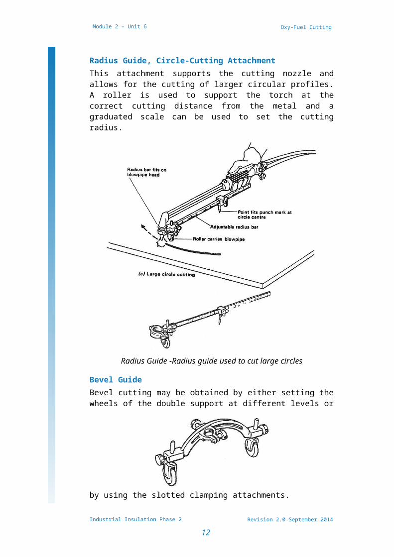
Radius Guide, Circle-Cutting AttachmentThis attachment supports the cutting nozzle and allows for the cutting of larger circular profiles. A roller is used to support the torch at the correct cutting distance from the metal and a graduated scale can be used to set the cutting radius.
Radius Guide -Radius guide used to cut large circles
Bevel GuideBevel cutting may be obtained by either setting the wheels of the double support at different levels or by using the
slotted clamping attachments.Bevel Guide
Industrial Insulation Phase 2
10
Oxy-Fuel Cutting
Revision 2.0 September 2014
Module 2 – Unit 6
2.5 Profile Machine for Automated Cutting
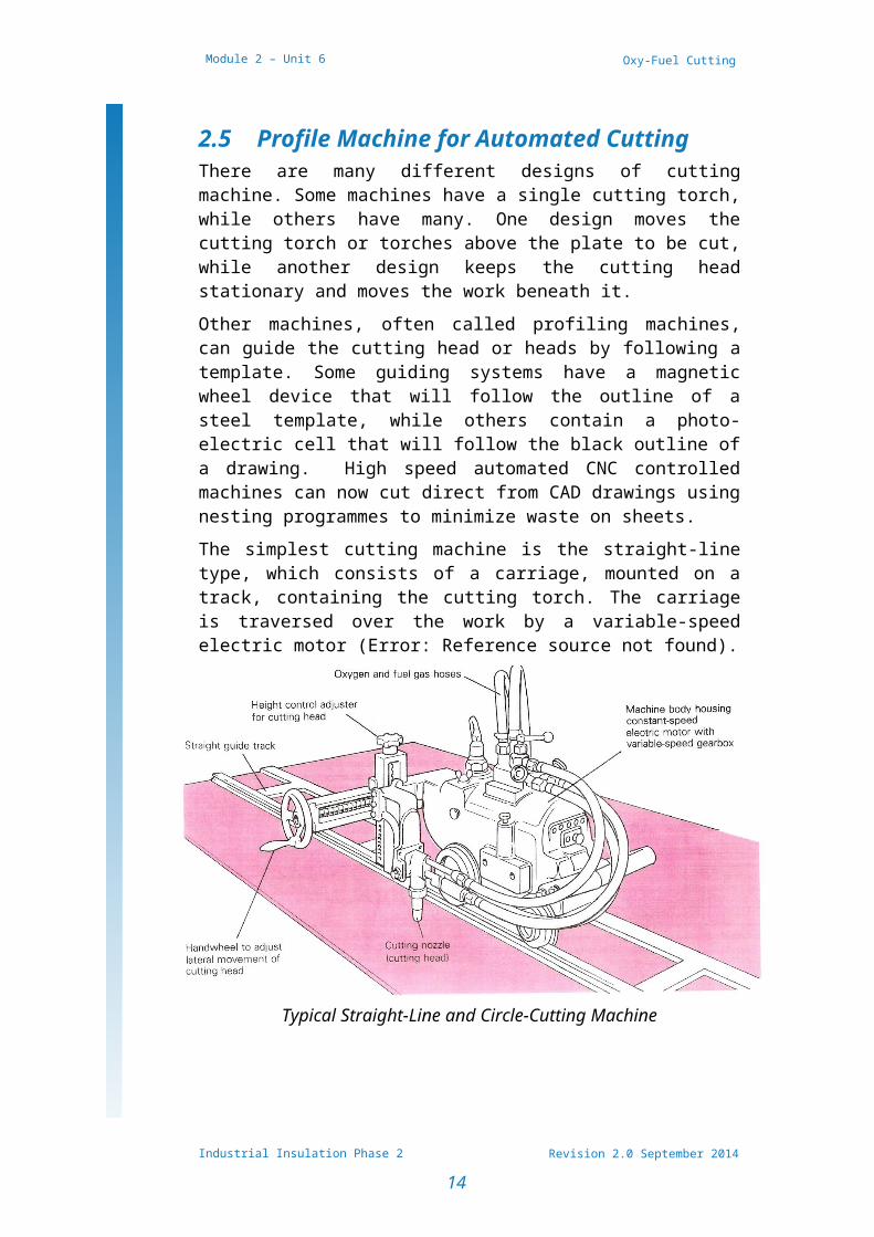
There are many different designs of cutting machine. Some machines have a single cutting torch, while others have many. One design moves the cutting torch or torches above the plate to be cut, while another design keeps the cutting head stationary and moves the work beneath it.Other machines, often called profiling machines, can guide the cutting head or heads by following a template. Some guiding systems have a magnetic wheel device that will follow the outline of a steel template, while others contain a photo-electric cell that will follow the black outline of a drawing. High speed automated CNC controlled machines can now cut direct from CAD drawings using nesting programmes to minimize waste on sheets.The simplest cutting machine is the straight-line type, which consists of a carriage, mounted on a track, containing the cutting torch. The carriage is traversed over the work by a variable-speed electric motor (Error: Reference sourcenot found).
Typical Straight-Line and Circle-Cutting Machine
Industrial Insulation Phase 2
11

Oxy-Fuel Cutting
Revision 2.0 September 2014
Module 2 – Unit 6
3.0Oxy-Fuel Cutting Techniques
Key Learning Points Identify techniques for general oxy-fuel cutting
applications Identify techniques for cutting thicker plate Identify techniques for cutting painted or
galvanized plate
3.1 Lighting and Adjusting the Cutting Flame
The procedure used for lighting a welding torch is adopted when lighting a cutting torch, but with one important difference. The fuel gas regulator is set to the correct working pressure in the normal way and the oxygen regulator is set to the correct working pressure with the cutting oxygen valve on the torch in the open position. The fuel gas is lit and the flame adjusted, in the same manner as for a welding torch, until it ceases to smoke. The heating oxygen valve is then opened and adjusted (similar to the neutral flame setting) until there is a series of nicely defined white inner cones in the flame (in the case of the multi-port nozzle) or a short white conical ring, if the nozzle is of the annular port type. At this stage the cutting oxygen valve is opened and the flame readjusted to a neutral condition. The oxygen cutting valve is then closed and the torch is ready for use.
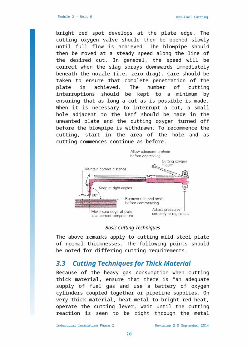
3.2 General Cutting TechniquesThe plate should be cleaned in the area where cutting will take place, and then positioned so as to be convenient for working (if possible). Invariably the flat position is the most convenient. The blowpipe should be held in a balanced position so that freedom of movement is possible. Hold the nozzle 3-5mm above before the plate surface and continue preheating until a bright red spot develops at the plate edge. The cutting oxygen valve should then be opened slowly until full flow is achieved. The blowpipe should then be moved at a steady speed along the line of the desired cut. In general, the speed will be correct when the slag sprays downwards immediately beneath the nozzle (i.e. zero drag). Care should be taken to ensure that complete penetration of the plate is achieved. The number of cutting
Industrial Insulation Phase 2
12
Oxy-Fuel Cutting
Revision 2.0 September 2014
Module 2 – Unit 6
interruptions should be kept to a minimum by ensuring that as long a cut as is possible is made. When it is necessary to interrupt a cut, a small hole adjacent to the kerf should be made in the unwanted plate and the cutting oxygen turned off before the blowpipe is withdrawn. To recommence the cutting, start in the area of the hole and as cutting commences continue as before.
Basic Cutting TechniquesThe above remarks apply to cutting mild steel plate of normal thicknesses. The following points should be noted for differing cutting requirements.
3.3 Cutting Techniques for Thick Material
Because of the heavy gas consumption when cutting thick material, ensure that there is "an adequate supply of fuel gas and use a battery of oxygen cylinders coupled together or pipeline supplies. On very thick material, heat metal to bright red heat, operate the cutting lever, wait until the cutting reaction is seen to be right through the metal thickness to the bottom edge, and then draw the blowpipe along.
3.4 Cutting Techniques for Painted or Galvanised Material
Clean the surface before starting to cut. It is often an advantage to incline the tip of the nozzle a little to help to undercut paint or scale. Unless ventilation is very good fume extraction should be installed at the point of cutting. In some cases it may be necessary to use a respirator as well.
Industrial Insulation Phase 2
13
Oxy-Fuel Cutting
Revision 2.0 September 2014
Module 2 – Unit 6
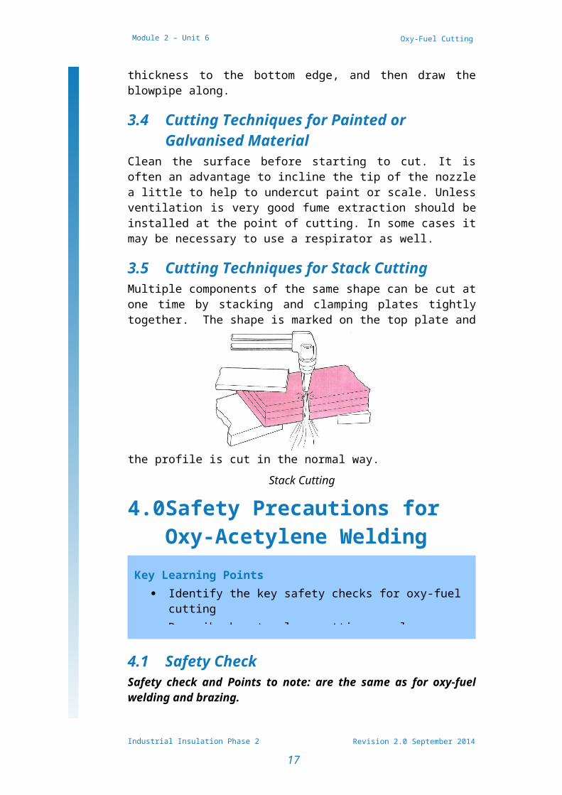
3.5 Cutting Techniques for Stack Cutting
Multiple components of the same shape can be cut at one time by stacking and clamping plates tightly together. The shape is marked on the top plate and the profile is cut in the
normal way.Stack Cutting
4.0Safety Precautions for Oxy-Acetylene Welding
Key Learning Points Identify the key safety checks for oxy-fuel cutting Describe how to clean cutting nozzles
4.1 Safety CheckSafety check and Points to note: are the same as for oxy-fuel welding and brazing.
Oxygen and acetylene cylinders must be securely stored in an upright position.
An oxyacetylene torch can produce a large amount of heat. Be aware that any objects you direct the flame towards will become hot.
Always have a suitable fire extinguisher near your work area.
Do not use an oxy-fuel torch near any flammable materials.
Make sure that you understand and observe all legislative and personal safety procedures when carrying out the following tasks. If you are unsure of what these are, ask your supervisor.
Industrial Insulation Phase 2
14
Oxy-Fuel Cutting
Revision 2.0 September 2014
Module 2 – Unit 6
If a cylinder falls over and breaks the main valve off, the cylinder will become a missile and cause extreme damage.
Wear a leather apron or similar protective clothing and welding gloves when using an oxyacetylene torch. T-shirts, nylon and polyester blend clothing will not provide enough protection. Ultraviolet light and sparks of hot metal will pass through them.
Always use proper welding goggles. Do not use sunglasses because they do not filter the extreme ultraviolet light as effectively. The plastic used in sunglass lenses will not protect your eyes from sparks.
Never point the lighted flame toward another person or any flammable material.
Always light the oxyacetylene torch with the striker. A cigarette lighter or match would put your hand too close to the igniting tip.
Wherever possible, use a heat shield behind the component you are heating. This will prevent nearby objects from becoming hot.
After heating a piece of metal, label it as "HOT" with a piece of chalk so that others will not attempt to pick it up.
Industrial Insulation Phase 2
15
Oxy-Fuel Cutting
Revision 2.0 September 2014
Module 2 – Unit 6
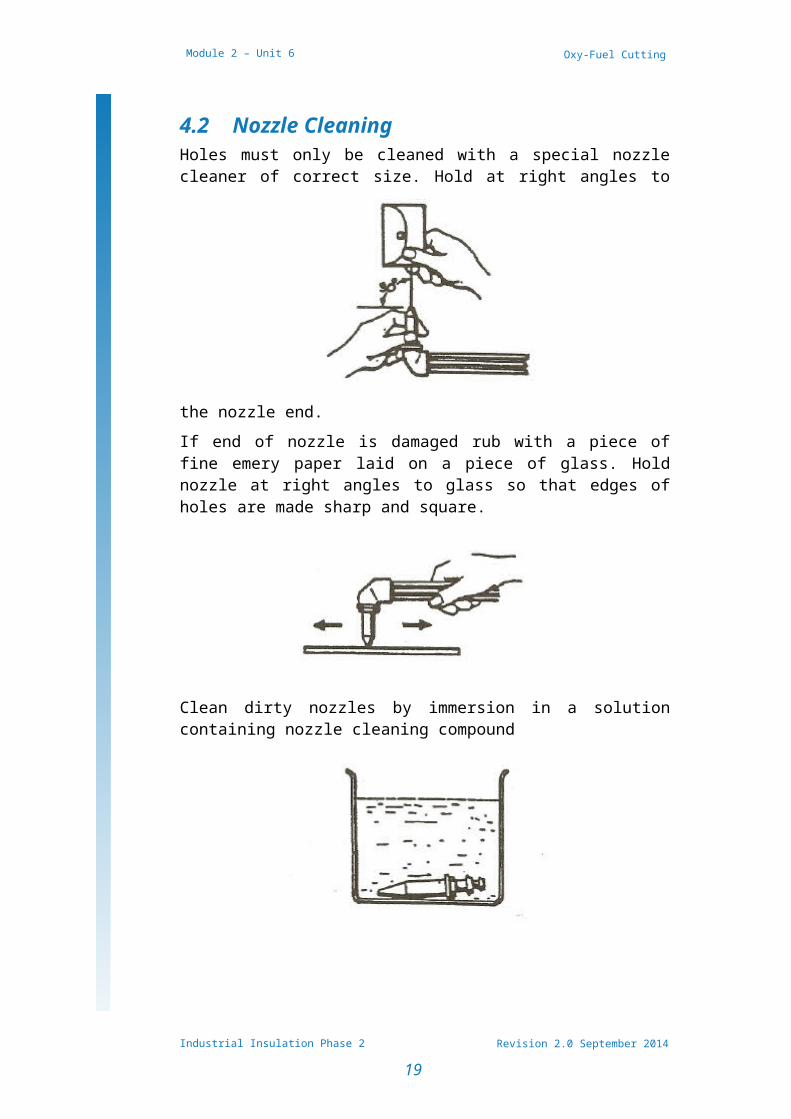
4.2 Nozzle CleaningHoles must only be cleaned with a special nozzle cleaner of correct size. Hold at right angles to the nozzle end.
If end of nozzle is damaged rub with a piece of fine emery paper laid on a piece of glass. Hold nozzle at right angles to glass so that edges of holes are made sharp and square.
Clean dirty nozzles by immersion in a solution containing nozzle cleaning compound
Industrial Insulation Phase 2
16
Oxy-Fuel Cutting
Revision 2.0 September 2014
Module 2 – Unit 6
5.0Assembling Oxy-Fuel Cutting Equipment
Key Learning Points Identify step-by-step instructions to set up oxy-fuel
cutting equipment Setting gas pressures for oxy-fuel cutting Identify the shutdown procedure for turning off
oxy-fuel cutting equipment
5.1 Step by Step Instruction1. Check equipment: 2. Purge the system: 3. Install the torch handle: 4. Connect the hoses: 5. Install the correct tip:6. Adjust the pressure of the gas flow:7. Turn on the gases: 8. Check the area: 9. Ignite the torch 10.Adjust the flame.
Industrial Insulation Phase 2
17
Oxy-Fuel Cutting
Revision 2.0 September 2014
Module 2 – Unit 6
5.2 Setting Gas Pressure for Oxy-Fuel Cutting
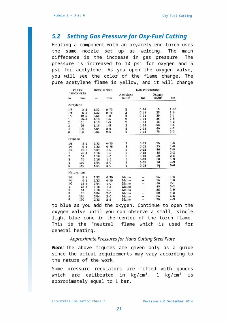
Heating a component with an oxyacetylene torch uses the same nozzle set up as welding. The main difference is the increase in gas pressure. The pressure is increased to 10 psi for oxygen and 5 psi for acetylene. As you open the oxygen valve, you will see the color of the flame change. The pure acetylene flame is yellow, and it will change to blue as you add the oxygen. Continue to open the oxygen valve until you can observe a small, single light blue cone in
the center of the torch flame. This is the “neutral” flame which is used for general heating.
Approximate Pressures for Hand Cutting Steel PlateNote: The above figures are given only as a guide since the actual requirements may vary according to the nature of the work.Some pressure regulators are fitted with gauges which are calibrated in kg/cm². 1 kg/cm² is approximately equal to 1 bar.
5.3 Shut Down ProcedureWhen you have finished with the cutting torch, you will need to shut down the equipment. Turn off the acetylene valve on the torch handle. This will extinguish the flame.
Industrial Insulation Phase 2
18
Oxy-Fuel Cutting
Revision 2.0 September 2014
Module 2 – Unit 6
Turn off the oxygen valve on the torch handle. Next, remove your safety goggles or mask and your welding gloves. Turn the main cylinder valve clockwise on the top of both gas cylinders. Now open the two valves on the torch handle to “bleed” the system. Turn both the oxygen and acetylene regulator handles counter-clockwise until they are loose. Close both valves on the torch handle. Put the handle and tips away, and return the gas cylinders and their hoses to their proper storage area.
6.0Effects of Heat on Mild Steel
Key Learning Points Identify why oxy-fuel cutting works Identify how an oxy-fuel torch can be used to case
harden metals
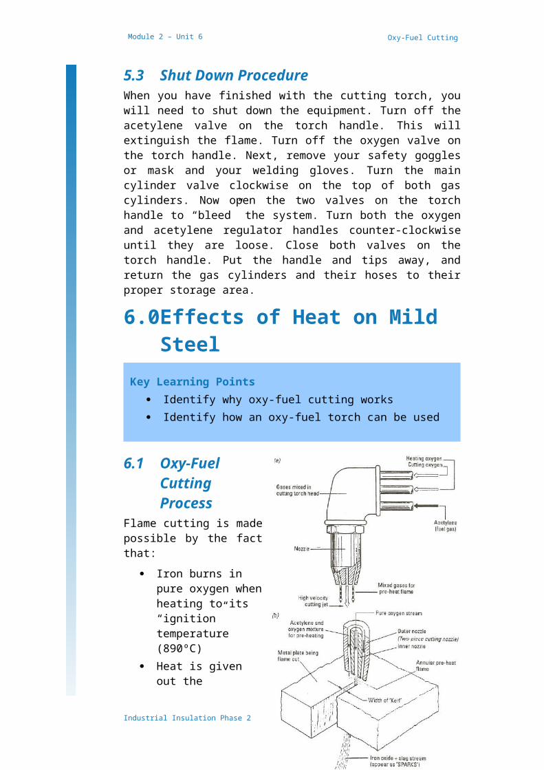
6.1 Oxy-Fuel Cutting ProcessFlame cutting is made possible by the fact that:
Iron burns in pure oxygen when heating to its “ignition” temperature (890ºC)
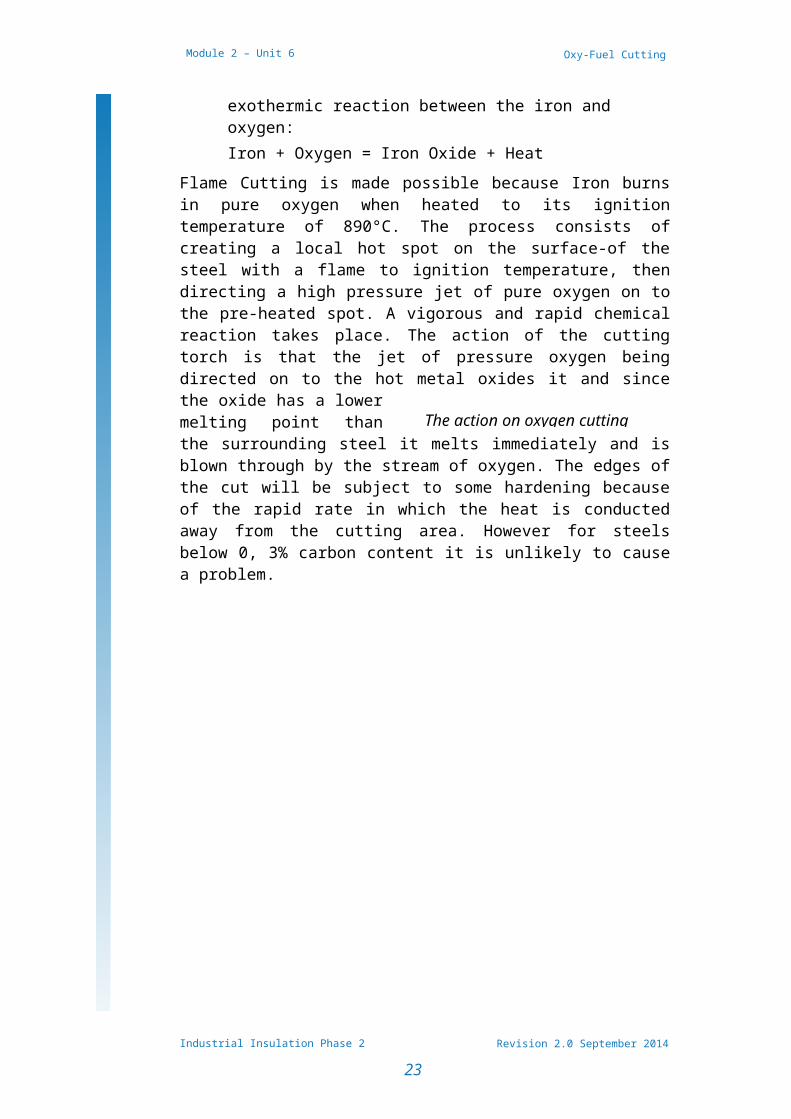
Heat is given out the exothermic reaction between the iron and oxygen:Iron + Oxygen =
Iron Oxide + HeatFlame Cutting is made possible because Iron burns in pure oxygen when heated to its ignition temperature of 890°C. The process consists of creating a local hot spot on the surface-of the steel with a flame to ignition temperature, then directing a high pressure jet of pure oxygen on to the pre-heated spot. A
Industrial Insulation Phase 2
19The action on oxygen cutting
Oxy-Fuel Cutting
Revision 2.0 September 2014
Module 2 – Unit 6
vigorous and rapid chemical reaction takes place. The action of the cutting torch is that the jet of pressure oxygen being directed on to the hot metal oxides it and since the oxide has a lower melting point than the surrounding steel it melts immediately and is blown through by the stream of oxygen. The edges of the cut will be subject to some hardening because of the rapid rate in which the heat is conducted away from the cutting area. However for steels below 0, 3% carbon content it is unlikely to cause a problem.
Industrial Insulation Phase 2
20
Oxy-Fuel Cutting
Revision 2.0 September 2014
Module 2 – Unit 6
6.1 Flame HardeningThe oxyacetylene flame can be used to harden the surface of hardenable steel, including stainless steels, to provide better wearing qualities. The carbon content of the steel should be 0.35 percent or higher for appreciable hardening. The best range for the hardening process is 0.40 to 0.50 percent carbon. In this process, the steel is heated to its critical temperature and then quenched, usually with water. Steels containing 0.70 percent carbon or higher can be treated in the same manner, except that compressed air or water sprayed by compressed air, is used to quench the parts less rapidly to prevent surface checking. Oil is used for quenching some steel compositions. The oxyacetylene flame is used merely as a heat source and involves no change in the composition of the steels as in case hardening where carbon or nitrogen is introduced into the surface. In case hardening, the thickness of the hardened area ranges from 0 to 0.020 in. (0 to 0.508 mm). Ordinary welding torches are used for small work, but for most flame hardening work, water-cooled torches are necessary. Tips or burners are of the multi-flame type. They are water cooled since they must operate for extended periods without backfiring. Where limited areas are to be hardened, the torch is moved back and forth over the part until the area is heated above the critical temperature. Then the area is quenched.
Industrial Insulation Phase 2
21
Oxy-Fuel Cutting
Revision 2.0 September 2014
Module 2 – Unit 6
Exercises Complete oxy-acetylene cutting exercises as per
Exercise Nos. 2.2.6a and 2.2.6b Cut sections of mild steel pipe using the oxyacetylene
cutting process Complete the pipe cutting exercises as per Exercise
Nos. 2.2.6 c and 2.2.6d
Additional ResourcesTitle Author Ref. CodeThe Induction Book, “Code of Behaviour & Health & Safety Guidelines”
SOLAS
Basic Welding and Fabrication W Kenyon ISBN 0-582-
00536-LFundamentals of Fabrication and Welding Engineering
FJM Smith ISBN 0-582-09799-1
Workshop processes, practices and materials, 3rd edition, Elsevier Science & Technology
Black, Bruce J 2004
ISBN-13: 9780750660730
New Engineering Technology
Lawrence Smyth & Liam Hennessy
ISBN 086 1674480
Videos Understanding welding fumes Welder on Site…Be Aware (Vocam) Powered hand tool safety (Vocam) Industrial Ergonomics (Vocam)
Available from:Vocam IrelandCircle Organisation LtdFriar Street, Thurles, Co Tipperary, IrelandTel: +353 504 24666
Industrial Insulation Phase 2
22
Castleforbes HouseCastleforbes Road
Dublin 1