Embed Size (px)
Citation preview
UNIT - V
Special Motors
Hysteresis motor
Reluctance motor
Stepper motor
Synchros
Linear induction motor
Permanent magnet Brushless DC motor
1Machine-3
EVERYTHING!!!!!
• At home:• motors• The fan over the stove and in the microwave oven • The dispose-all under the sink • The blender • The can opener • The refrigerator - Two or three in fact:
– one for the compressor, – one for the fan inside the refrigerator, – as well as one in the icemaker
• The mixer • The tape player in the answering machine • Probably even the clock on the oven • The washer • The dryer• The electric screwdriver• The vacuum cleaner and the Dust buster mini-vac• The electric saw • The electric drill • The furnace blower • The fan • The electric toothbrush • The hair dryer• The electric razor
• Your car is loaded with electric motors:
• Power windows (a motor in each window)
• Power seats (up to seven motors per seat)
• Fans for the heater and the radiator
• Windshield wipers
• The starter motor
• Electric radio antennas
• Motors in all sorts of places:
• Your iPod
• Several in the VCR
• Several in a CD player or tape deck
• Many in a computer
• Most toys that move
• Electric clocks
• The garage door opener
• Aquarium pumps
2
HYSTERESIS MOTOR
3
HYSTERESIS MOTOR
The phenomenon of hysteresis can be used to produce
mechanical torque.
A hysteresis motor is basically a synchronous motor
with uniform air gap and without d.c. excitation.
These may operate from single phase or three phase
source.
Its operation depends on hysteresis effect i.e.
magnetization produced in ferromagnetic material lags
behind magnetic force.
4
ROTOR
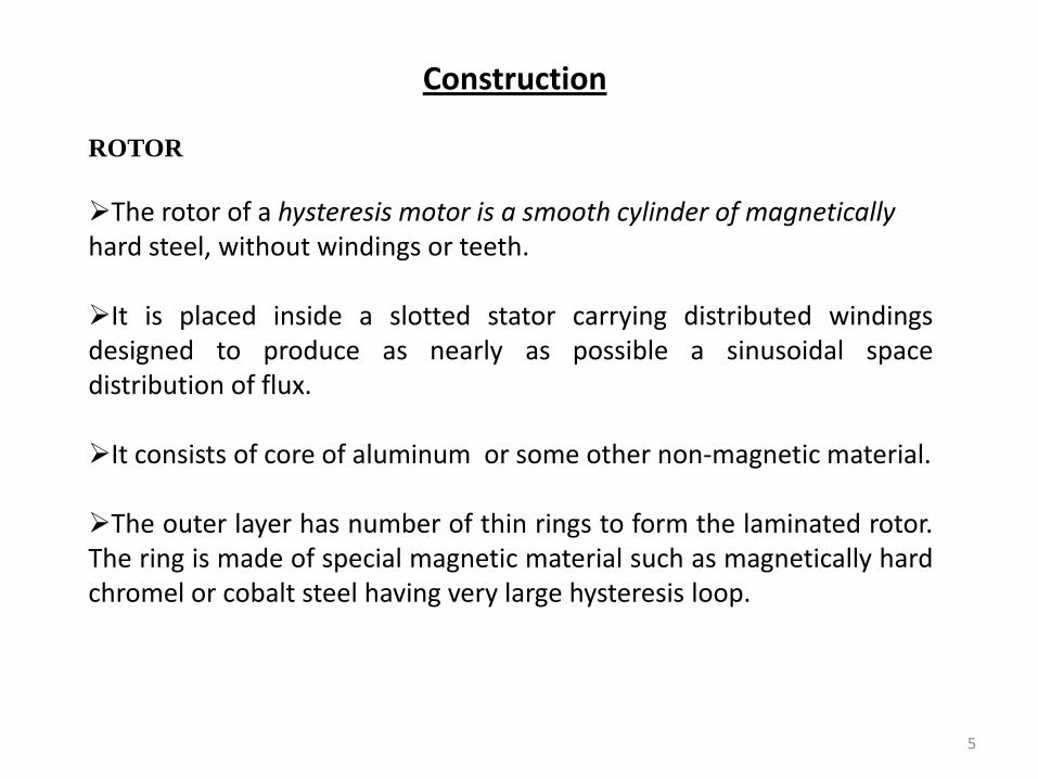
The rotor of a hysteresis motor is a smooth cylinder of magneticallyhard steel, without windings or teeth.
It is placed inside a slotted stator carrying distributed windingsdesigned to produce as nearly as possible a sinusoidal spacedistribution of flux.
It consists of core of aluminum or some other non-magnetic material.
The outer layer has number of thin rings to form the laminated rotor.The ring is made of special magnetic material such as magnetically hardchromel or cobalt steel having very large hysteresis loop.
Construction
5
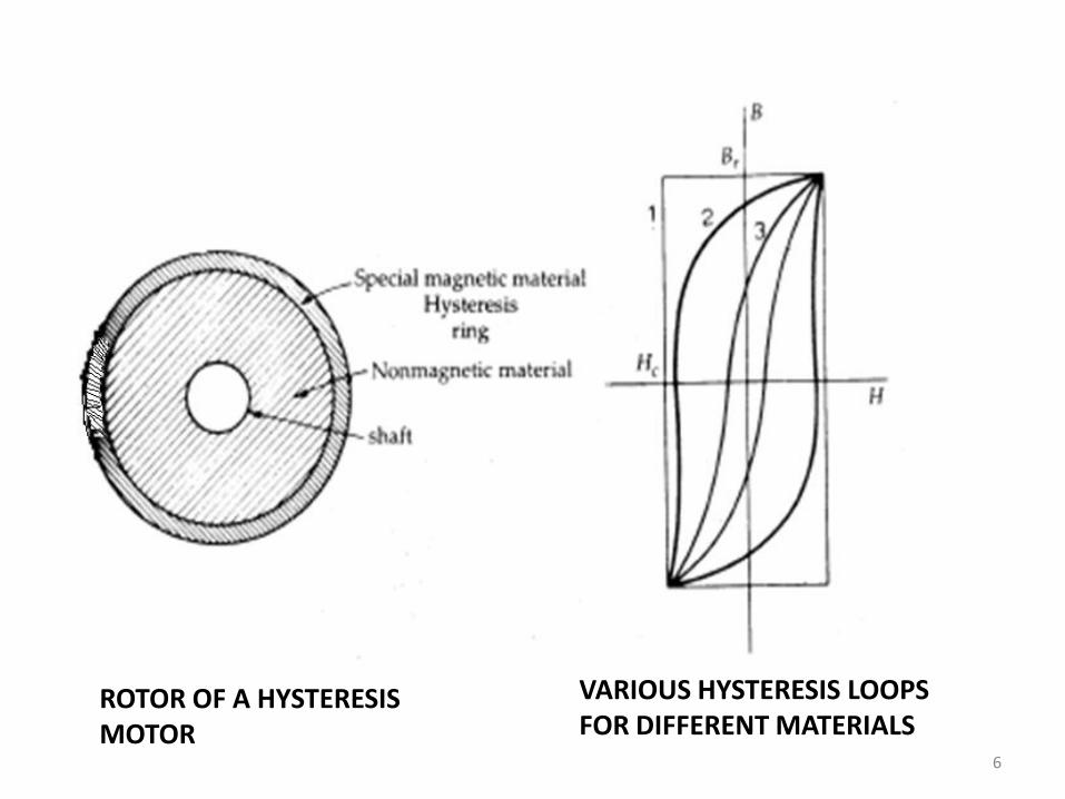
ROTOR OF A HYSTERESIS MOTOR
VARIOUS HYSTERESIS LOOPS FOR DIFFERENT MATERIALS
6
STATOR :
Rotor is placed inside a slotted stator carrying distributed windingsdesigned to produce as nearly as possible a sinusoidal spacedistribution of flux.
In single-phase motors, the stator windings usually are of thepermanent-split-capacitor type.
The capacitor is chosen so as to result in approximately balancedtwo-phase conditions within the motor windings.
The stator then produces a primarily space-fundamental air-gapfield revolving at synchronous speed.
7
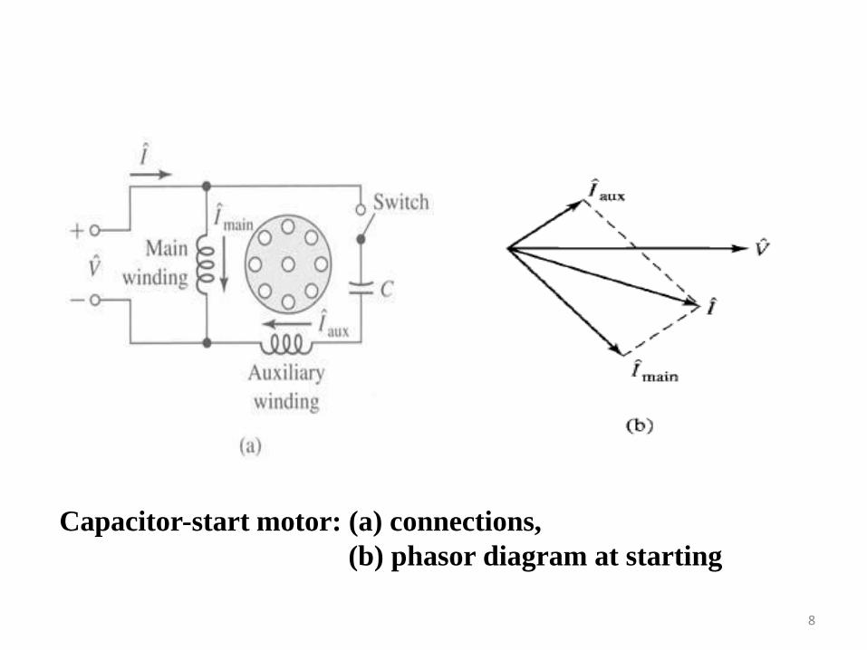
Capacitor-start motor: (a) connections,
(b) phasor diagram at starting
8
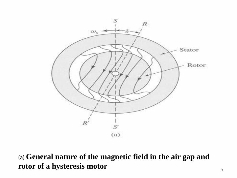
(a) General nature of the magnetic field in the air gap and
rotor of a hysteresis motor9
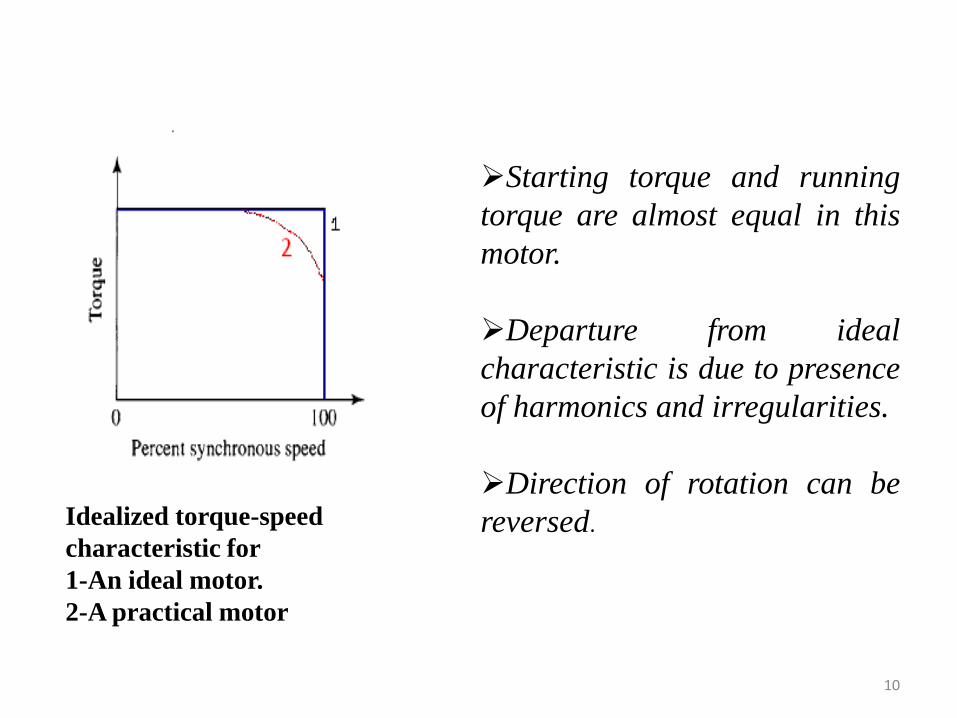
Idealized torque-speed
characteristic for
1-An ideal motor.
2-A practical motor
Starting torque and running
torque are almost equal in this
motor.
Departure from ideal
characteristic is due to presence
of harmonics and irregularities.
Direction of rotation can be
reversed.
10
APPLICATIONS
Due to noiseless operation, it is used in sound recording instruments, sound producing equipments, high quality record players, tape recorders, electric clocks , teleprinters , timing devices etc.
11
RELUCTANCE MOTOR
12
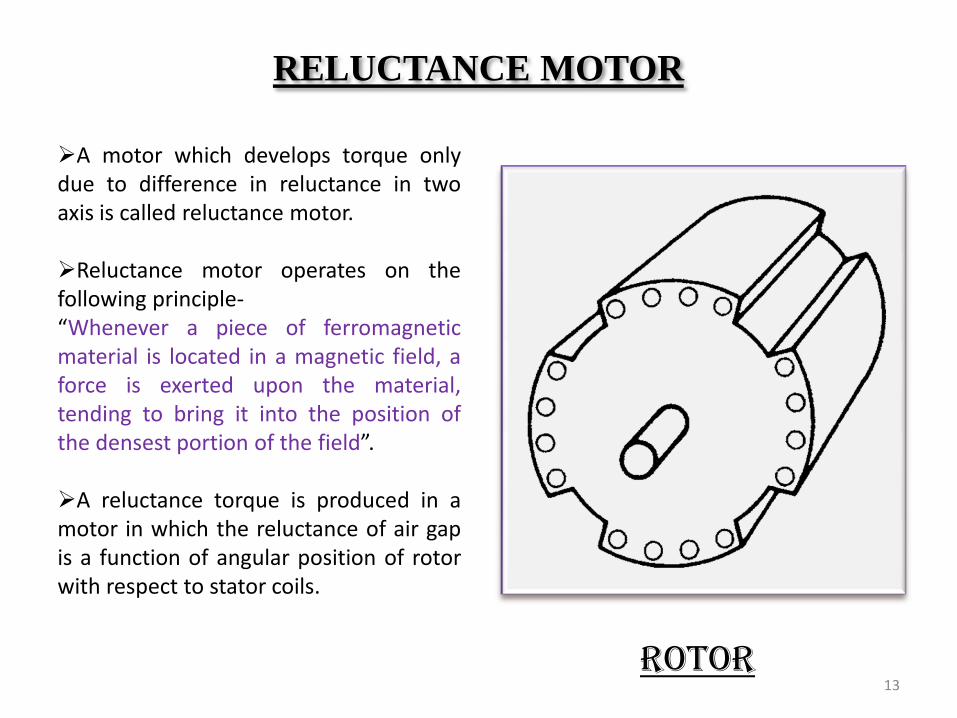
RELUCTANCE MOTOR
A motor which develops torque onlydue to difference in reluctance in twoaxis is called reluctance motor.
Reluctance motor operates on thefollowing principle-“Whenever a piece of ferromagneticmaterial is located in a magnetic field, aforce is exerted upon the material,tending to bring it into the position ofthe densest portion of the field”.
A reluctance torque is produced in amotor in which the reluctance of air gapis a function of angular position of rotorwith respect to stator coils.
ROTOR13
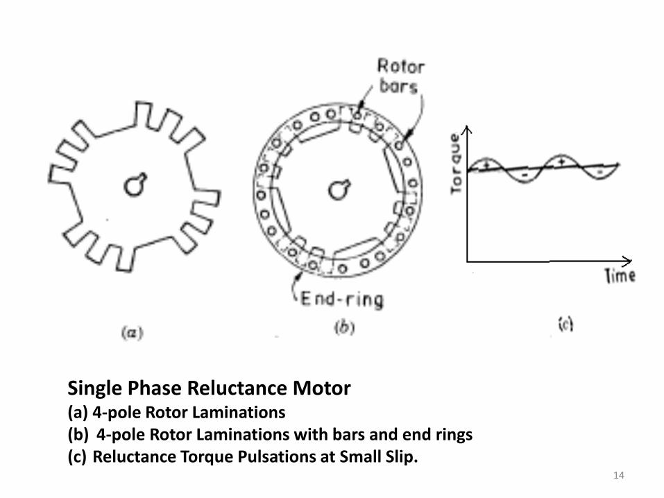
Single Phase Reluctance Motor(a) 4-pole Rotor Laminations(b) 4-pole Rotor Laminations with bars and end rings(c) Reluctance Torque Pulsations at Small Slip.
14
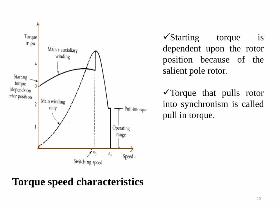
Torque speed characteristics
Starting torque is
dependent upon the rotor
position because of the
salient pole rotor.
Torque that pulls rotor
into synchronism is called
pull in torque.
15
ADVANTAGES
No d.c. supply is necessary for rotor.
Constant speed characteristics.
Robust construction .(no slip rings, no brushes, no dc field
winding)
Less maintenance.
Low cost
DISADVANTAGES
Less efficiency.
Poor power factor.
Cannot accelerate high inertia loads to synchronous speed.
Less capacity to drive the loads.
16
APPLICATIONS
Signaling devices Controlling apparatus Automatic regulators Recording instruments Clocks, telephones, teleprinters, phonograph e.t.c.
17
LINEAR INDUCTION MOTOR
18
Linear Induction Motor
It gives linear or translational motion instead of rotational
motion.
Stator forms the primary and rotor forms the secondary.
The analysis of linear machines is quite similar to that of rotary
machines. In general, linear dimensions and displacements replace
angular ones, and forces replace torques.
19
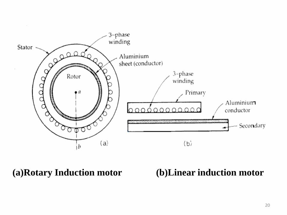
(a)Rotary Induction motor (b)Linear induction motor
20
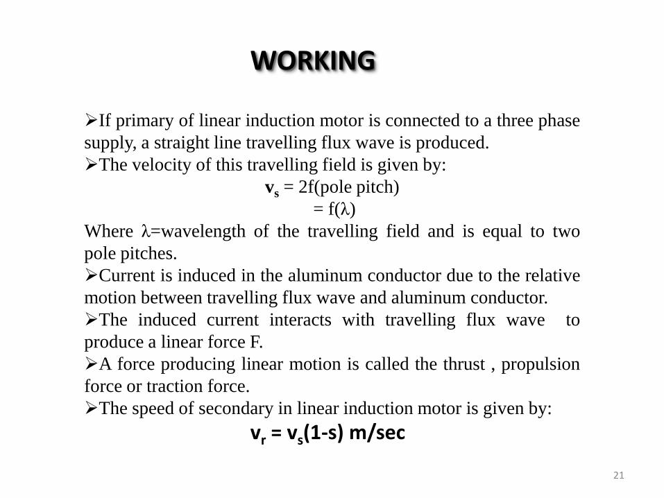
If primary of linear induction motor is connected to a three phase
supply, a straight line travelling flux wave is produced.
The velocity of this travelling field is given by:
vs = 2f(pole pitch)
= f(λ)
Where λ=wavelength of the travelling field and is equal to two
pole pitches.
Current is induced in the aluminum conductor due to the relative
motion between travelling flux wave and aluminum conductor.
The induced current interacts with travelling flux wave to
produce a linear force F.
A force producing linear motion is called the thrust , propulsion
force or traction force.
The speed of secondary in linear induction motor is given by:
vr = vs(1-s) m/sec
WORKING
21
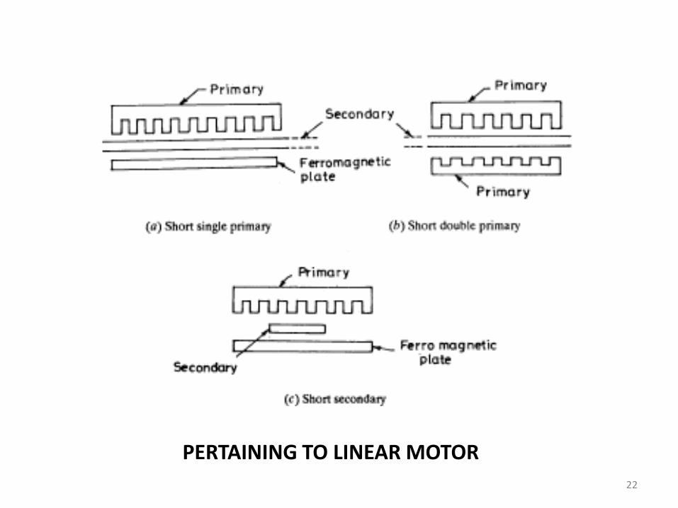
PERTAINING TO LINEAR MOTOR
22
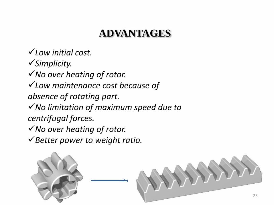
ADVANTAGES
Low initial cost.Simplicity.No over heating of rotor.Low maintenance cost because of absence of rotating part.No limitation of maximum speed due to centrifugal forces.No over heating of rotor.Better power to weight ratio.
23
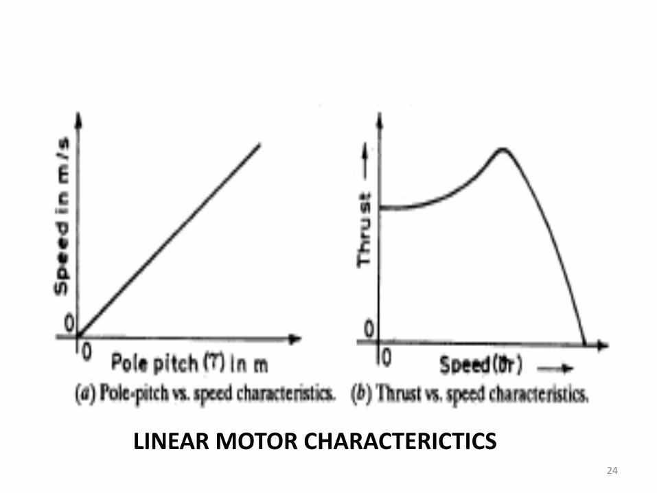
LINEAR MOTOR CHARACTERICTICS24
APPLICATIONS
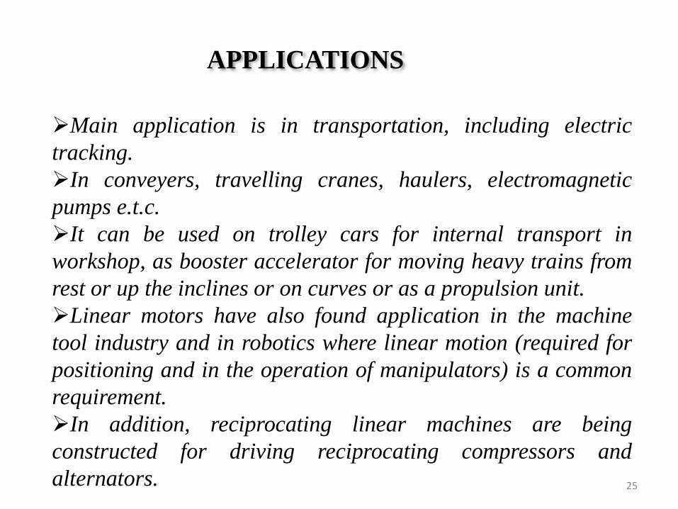
Main application is in transportation, including electric
tracking.
In conveyers, travelling cranes, haulers, electromagnetic
pumps e.t.c.
It can be used on trolley cars for internal transport in
workshop, as booster accelerator for moving heavy trains from
rest or up the inclines or on curves or as a propulsion unit.
Linear motors have also found application in the machine
tool industry and in robotics where linear motion (required for
positioning and in the operation of manipulators) is a common
requirement.
In addition, reciprocating linear machines are being
constructed for driving reciprocating compressors and
alternators. 25
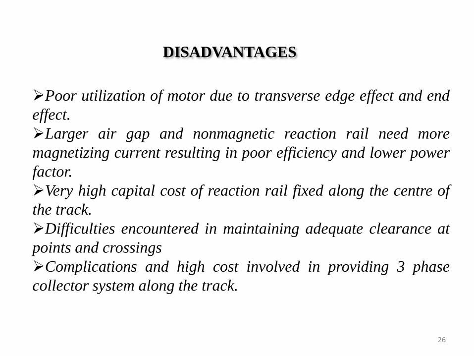
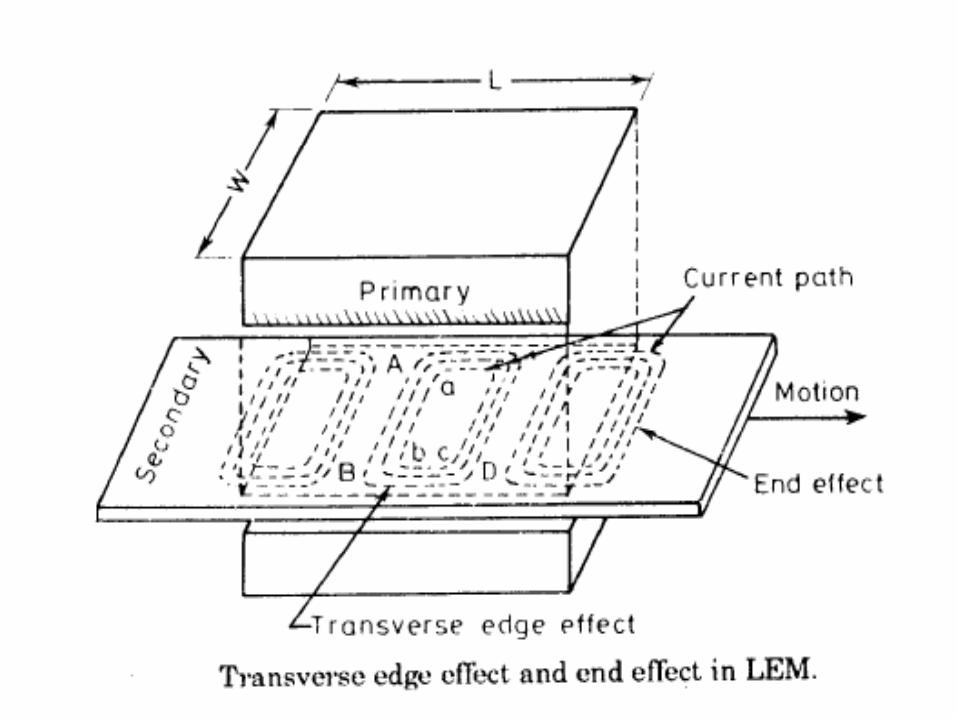
DISADVANTAGES
Poor utilization of motor due to transverse edge effect and end
effect.
Larger air gap and nonmagnetic reaction rail need more
magnetizing current resulting in poor efficiency and lower power
factor.
Very high capital cost of reaction rail fixed along the centre of
the track.
Difficulties encountered in maintaining adequate clearance at
points and crossings
Complications and high cost involved in providing 3 phase
collector system along the track.
26
27
STEPPER MOTOR
28
Why a Stepper Motor ?
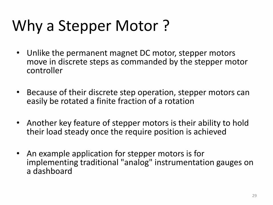
• Unlike the permanent magnet DC motor, stepper motors move in discrete steps as commanded by the stepper motor controller
• Because of their discrete step operation, stepper motors can easily be rotated a finite fraction of a rotation
• Another key feature of stepper motors is their ability to hold their load steady once the require position is achieved
• An example application for stepper motors is for implementing traditional "analog" instrumentation gauges on a dashboard
29
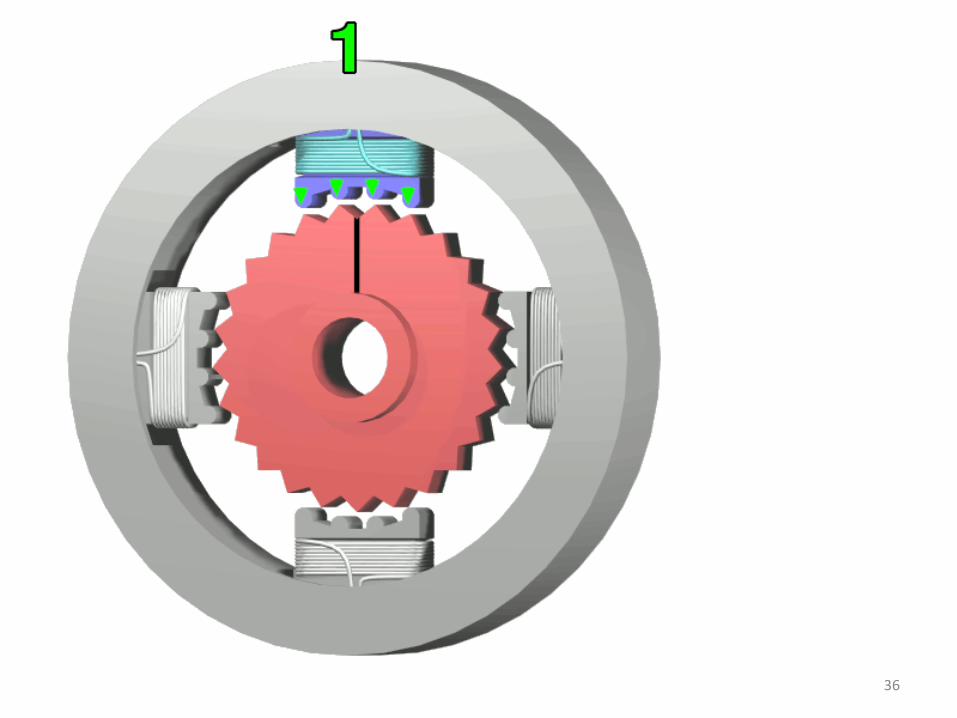
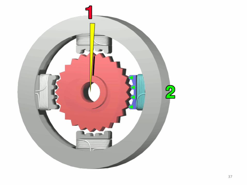
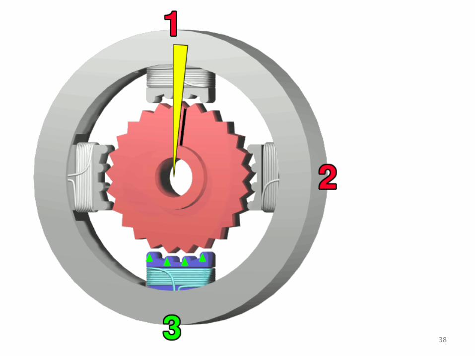
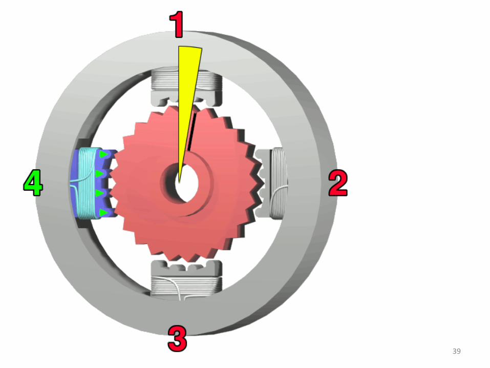
How Does a Stepper Motor Work ?
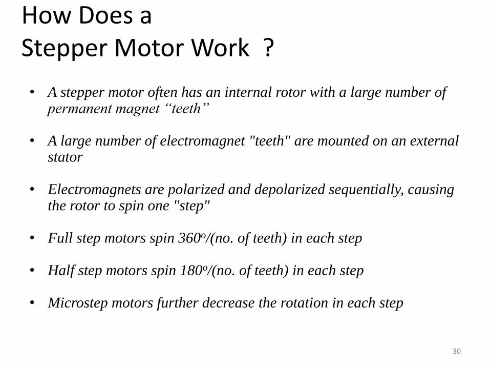
• A stepper motor often has an internal rotor with a large number of permanent magnet “teeth”
• A large number of electromagnet "teeth" are mounted on an external stator
• Electromagnets are polarized and depolarized sequentially, causing the rotor to spin one "step"
• Full step motors spin 360o/(no. of teeth) in each step
• Half step motors spin 180o/(no. of teeth) in each step
• Microstep motors further decrease the rotation in each step
30
Stepping motors can be regarded as a digitalelectromechanical device; it translates the inputdigital information in the form of electric pulses intodiscrete steps of shaft rotation.
If the number of input pulses send to the motor isknown ,the actual position of the driven job can beobtained.
Thus a digital position control system employing astepping motor needs no rotor position sensors andan expensive feedback loop.
31
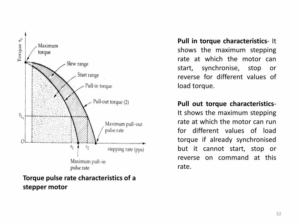
Torque pulse rate characteristics of a stepper motor
Pull in torque characteristics- Itshows the maximum steppingrate at which the motor canstart, synchronise, stop orreverse for different values ofload torque.
Pull out torque characteristics-It shows the maximum steppingrate at which the motor can runfor different values of loadtorque if already synchronisedbut it cannot start, stop orreverse on command at thisrate.
32

Stepper Motor Control• The stepper motor driver receives square wave pulse
train signals from a controller and converts the signals into the electrical pulses to step the motor
• This simple operation leads stepper motors to sometimes be called "digital motors"
• To achieve microstepping, however, the stepper motor must be driven by a (quasi) sinusoidal current that is expensive to implement
33
34
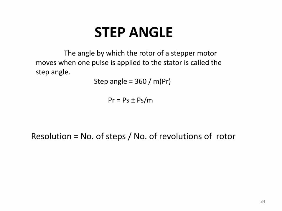
STEP ANGLEThe angle by which the rotor of a stepper motor
moves when one pulse is applied to the stator is called the step angle.
Step angle = 360 / m(Pr)
Pr = Ps ± Ps/m
Resolution = No. of steps / No. of revolutions of rotor
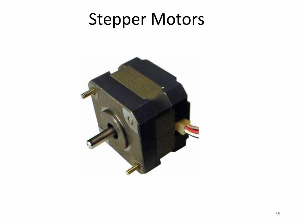
Stepper Motors
35
Stepper Motor Selection
• Permanent Magnet / Variable Reluctance
• Unipolar vs. Bipolar
• Number of Stacks
• Number of Phases
• Degrees Per Step
• Microstepping
• Pull-In/Pull-Out Torque
• Detent Torque
41
Three main types of stepper motors:
1. variable reluctance stepper motors
2. permanent magnet stepper motors
3. hybrid stepper motors
42
Variable reluctance stepper
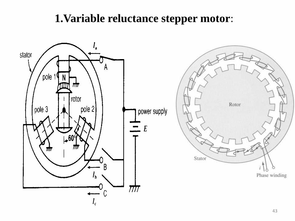
1.Variable reluctance stepper motor:
43
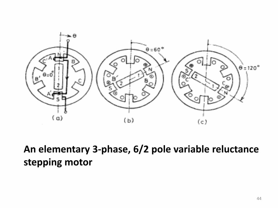
An elementary 3-phase, 6/2 pole variable reluctance stepping motor
44

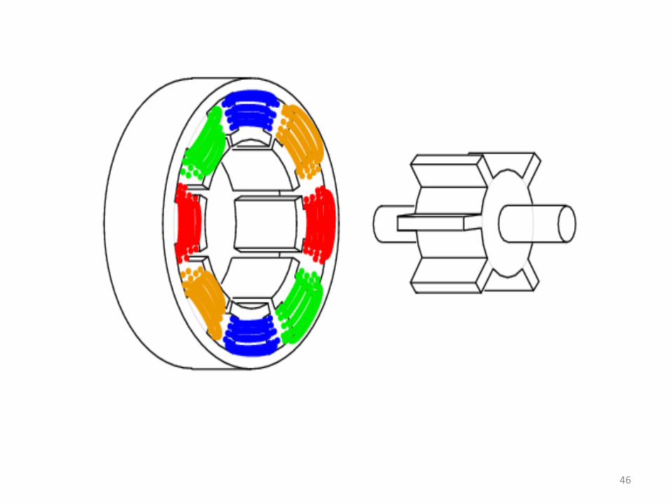
Four phase 8/6-pole VR stepping motor
45
46
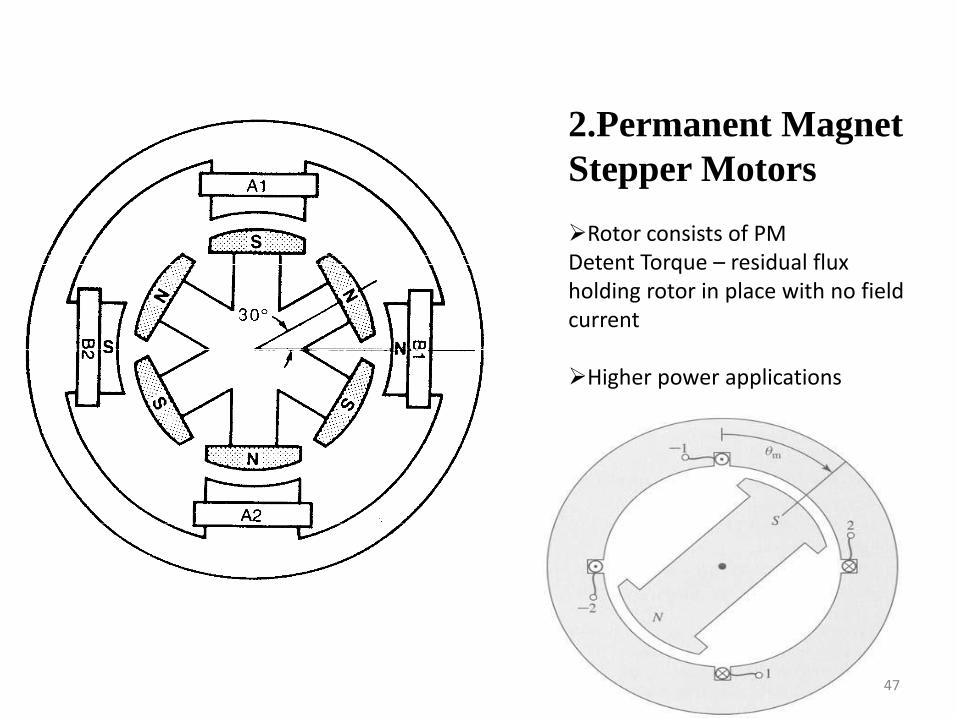
2.Permanent Magnet
Stepper Motors
Rotor consists of PMDetent Torque – residual flux holding rotor in place with no field current
Higher power applications
47
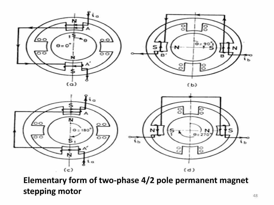
Elementary form of two-phase 4/2 pole permanent magnet stepping motor
48
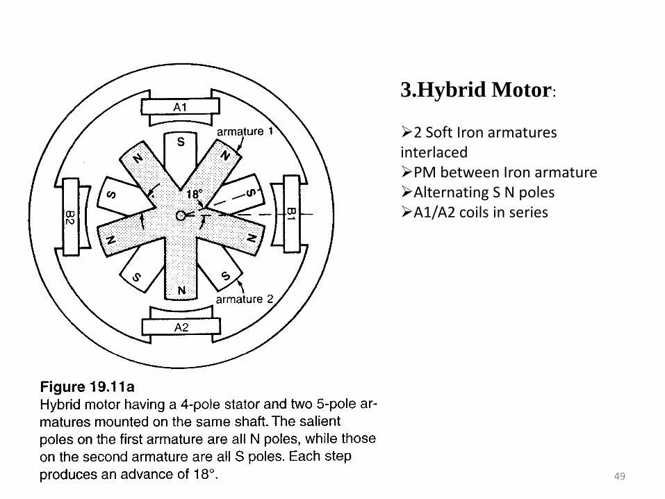
3.Hybrid Motor:
2 Soft Iron armatures interlacedPM between Iron armatureAlternating S N polesA1/A2 coils in series
49
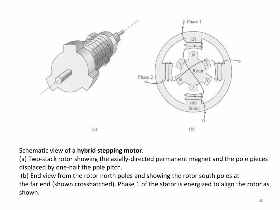
Schematic view of a hybrid stepping motor. (a) Two-stack rotor showing the axially-directed permanent magnet and the pole pieces displaced by one-half the pole pitch.(b) End view from the rotor north poles and showing the rotor south poles atthe far end (shown crosshatched). Phase 1 of the stator is energized to align the rotor asshown.
50
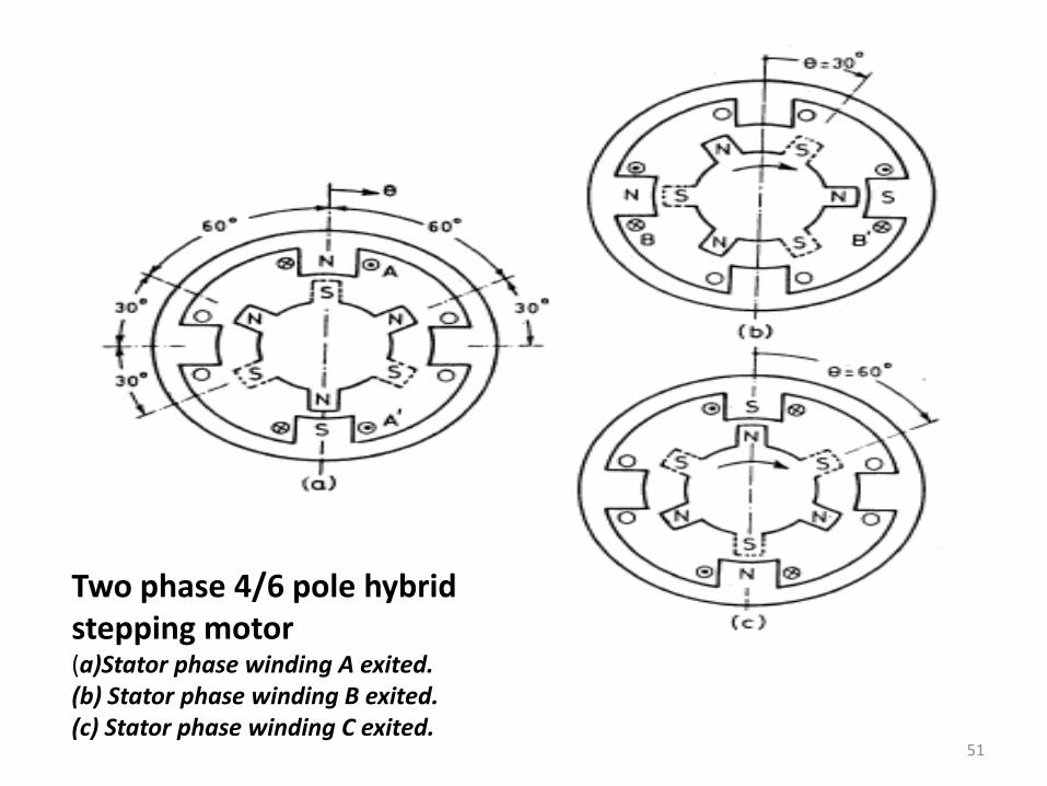
Two phase 4/6 pole hybrid stepping motor(a)Stator phase winding A exited.(b) Stator phase winding B exited.(c) Stator phase winding C exited.
51

52
APPLICATIONS
Typical applications include paper fed motors in
typewriters and printers , positioning of print heads ,
pens in x-y plotters , recording heads in computer disk
drives , robotics , textile industry, integrated circuit
fabrication and worktable and tool positioning in
numerically controlled machining equipments.
53
ADVANTAGES
1. The rotation angle of the motor is proportional to the input pulse.
2. The motor has full torque at standstill. (if the windings areenergized)
3. Precise positioning and repeatability of movement since good.
4. Excellent response to starting/stopping/reversing.
5. Very reliable since there are no Contact brushes in the motor.Therefore the life of the motor is simply dependant on the life ofthe bearing.
54
DISADVANTAGES
1. Resonances can occur if not properlycontrolled.
2. Not easy to operate at extremely highspeeds.
55
SYNCHROS
They are also known by trade name of positon
selsyn,autosyns and microsyns.
It is general name for self synchronising
machine, which when electrically energised and
electrically interconnected, exerts torque which
causes the mechanically independent shafts either
to run in synchronism or to make the rotor of one
unit follow the rotor position of other.
56
Types of synchros
1.Transmitter selsyn2.Receiver selsyn3.Differential selsyn4.Transformer selsyn
57
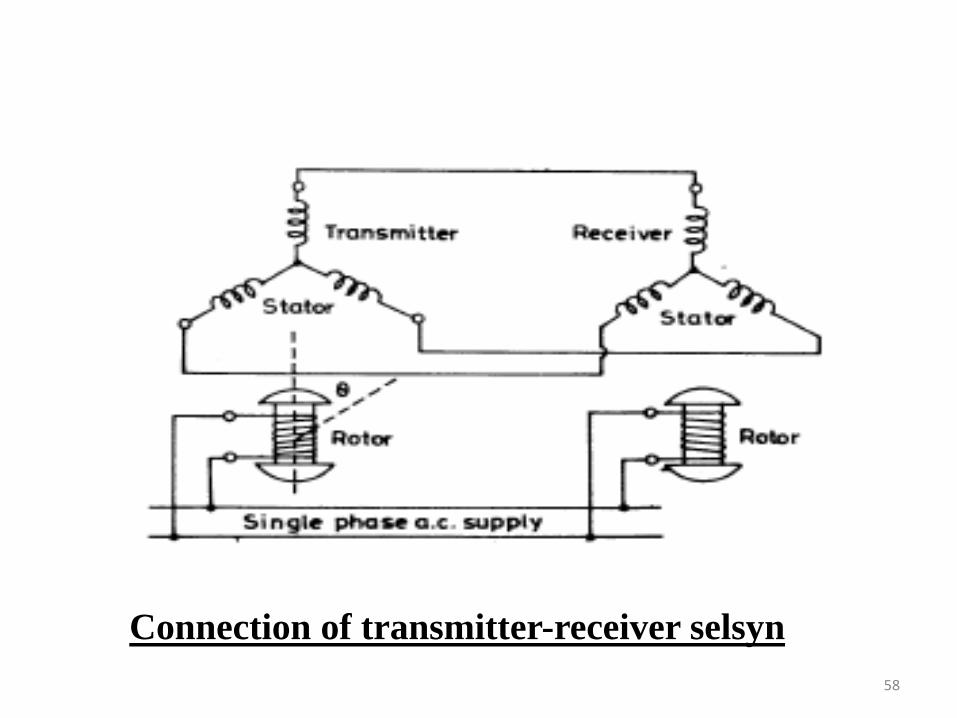
Connection of transmitter-receiver selsyn
58
59
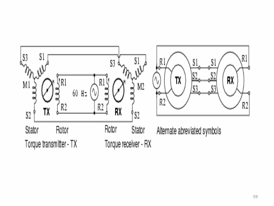
Small instrumentation selsyns, also known as sychros, use single phaseparalleled, AC energized rotors, retaining the 3-phase paralleled stators, whichare not externally energized. Synchros function as rotary transformers. If therotors of both the torque transmitter (TX) and torque receiver (RX) are at thesame angle, the phases of the induced stator voltages will be identical for both,and no current will flow. If one rotor be displaced from the other, the statorphase voltages will differ between transmitter and receiver. Stator current willflow developing torque. The receiver shaft is electrically slaved to thetransmitter shaft. Either the transmitter or receiver shaft may be rotated to turnthe opposite unit.Synchro stators are wound with 3-phase windings brought out to externalterminals. The single rotor winding of a torque transmitter or receiver isbrought out by brushed slip rings. Synchro transmitters and receivers areelectrically identical. However, a synchro receiver has inertial damping built in.A synchro torque transmitter may be substituted for a torque receiver.
60
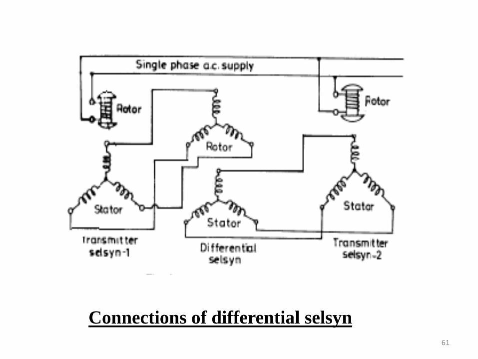
Connections of differential selsyn
61
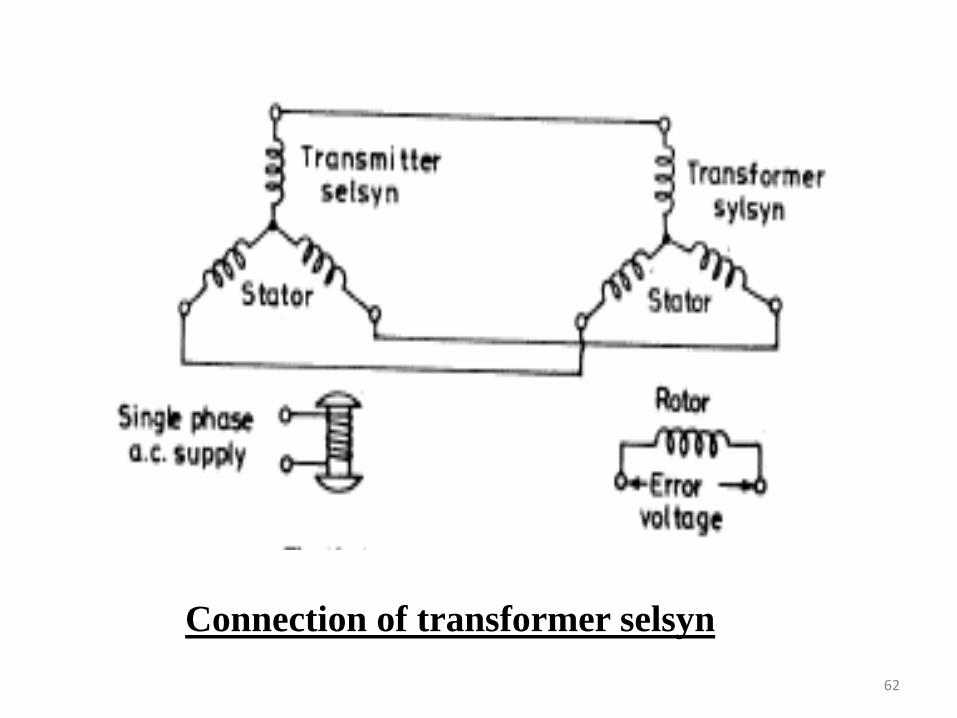
Connection of transformer selsyn
62
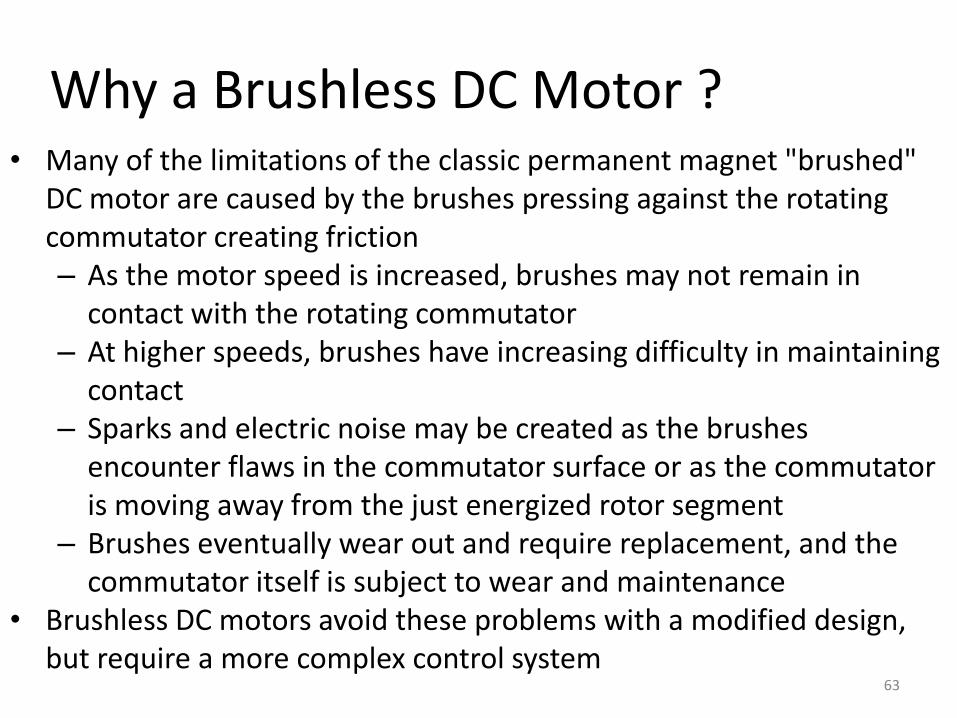
• Many of the limitations of the classic permanent magnet "brushed" DC motor are caused by the brushes pressing against the rotating commutator creating friction– As the motor speed is increased, brushes may not remain in
contact with the rotating commutator– At higher speeds, brushes have increasing difficulty in maintaining
contact– Sparks and electric noise may be created as the brushes
encounter flaws in the commutator surface or as the commutator is moving away from the just energized rotor segment
– Brushes eventually wear out and require replacement, and the commutator itself is subject to wear and maintenance
• Brushless DC motors avoid these problems with a modified design, but require a more complex control system
Why a Brushless DC Motor ?
63
A brushless d.c. motor is a polyphase synchronous motor
with a permanent magnet rotor.
It is a motor drive system which combines into one unit an
a.c. motor, solid state motor and a position sensor.
It has permanent magnet field poles on the rotor and
polyphase armature winding on the stator.
A brushless DC motor uses electronic sensors to detect the
position of the rotor without using a metallic contact.
Introduction
64
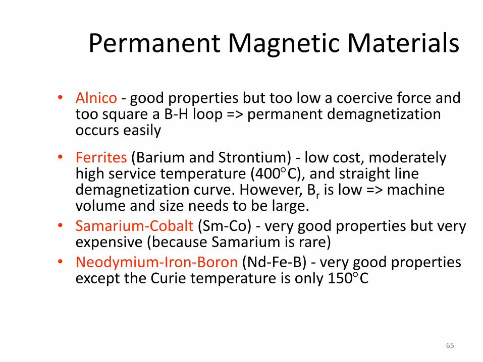
Permanent Magnetic Materials
• Alnico - good properties but too low a coercive force and too square a B-H loop => permanent demagnetization occurs easily
• Ferrites (Barium and Strontium) - low cost, moderately high service temperature (400C), and straight line demagnetization curve. However, Br is low => machine volume and size needs to be large.
• Samarium-Cobalt (Sm-Co) - very good properties but very expensive (because Samarium is rare)
• Neodymium-Iron-Boron (Nd-Fe-B) - very good properties except the Curie temperature is only 150C
65
• Using the sensor's signals, the polarity of the electromagnets’is switched by the motor control drive circuitry
• The motor can be easily synchronized to a clock signal, providing precise speed control
• Brushless DC motors may have:
– An external PM rotor and internal electromagnet stator
– An internal PM rotor and external electromagnet stator
WORKING
66
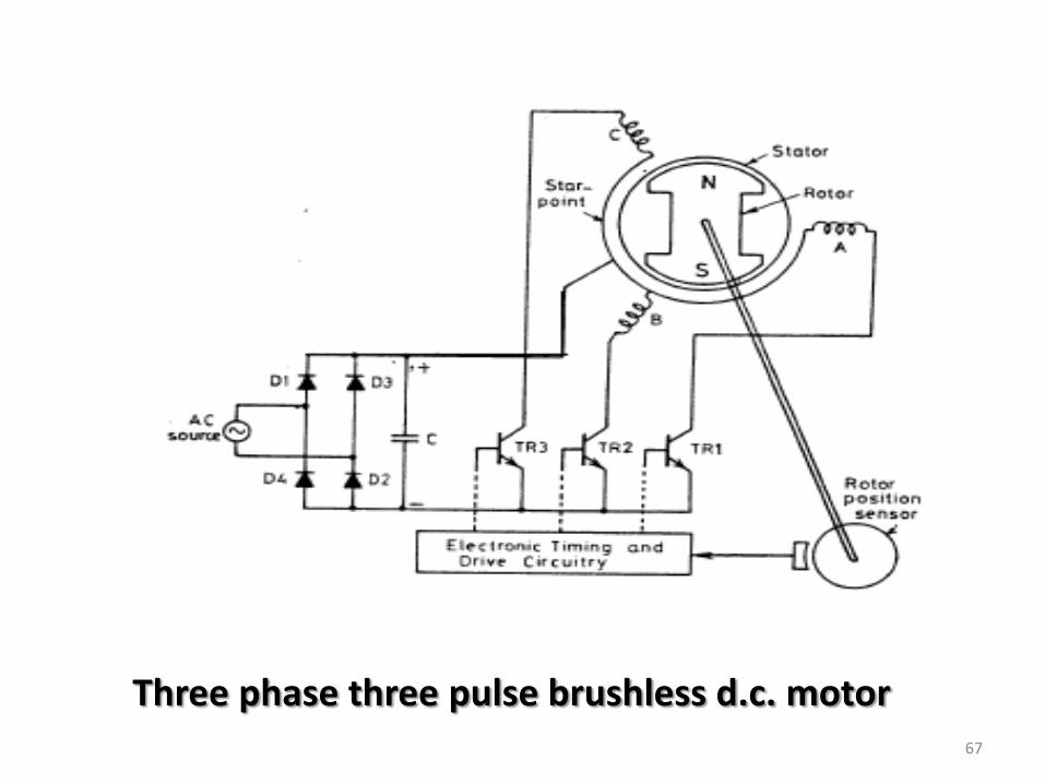
Three phase three pulse brushless d.c. motor67
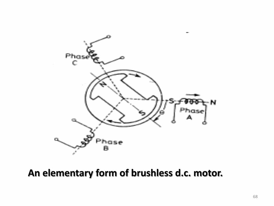
An elementary form of brushless d.c. motor.
68

Static torque angle characteristics of a brushless d.c. motor.
69
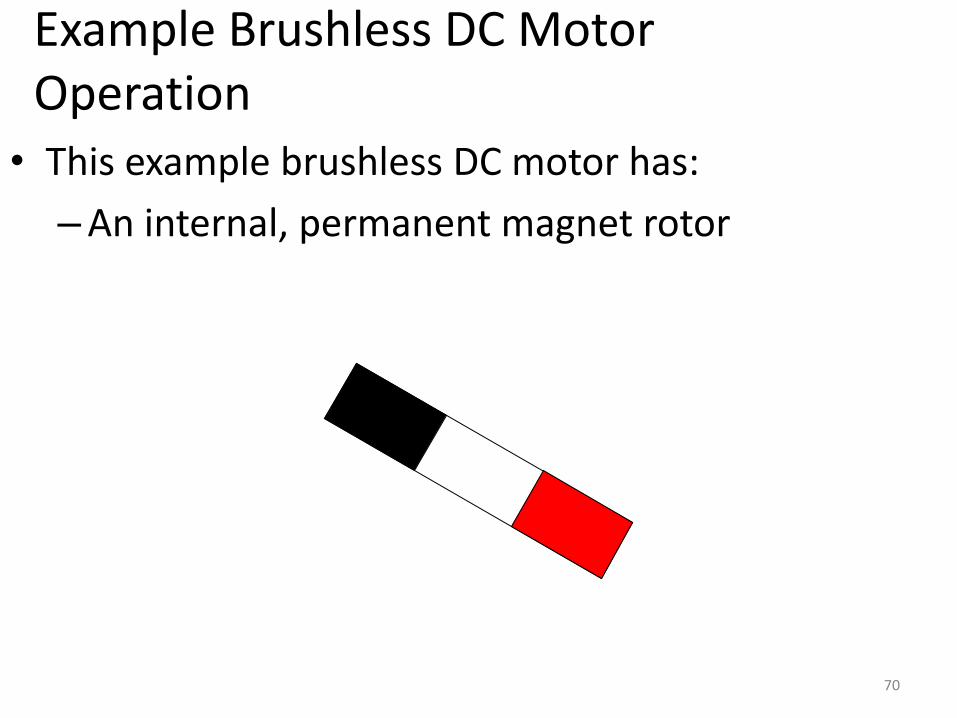
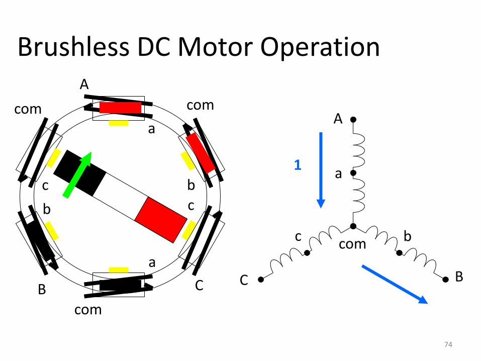
• This example brushless DC motor has:
–An internal, permanent magnet rotor
Example Brushless DC Motor Operation
70
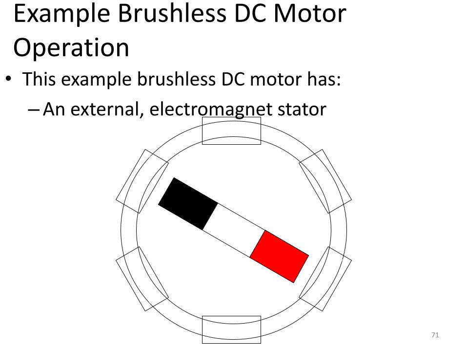
• This example brushless DC motor has:
–An external, electromagnet stator
Example Brushless DC Motor Operation
71
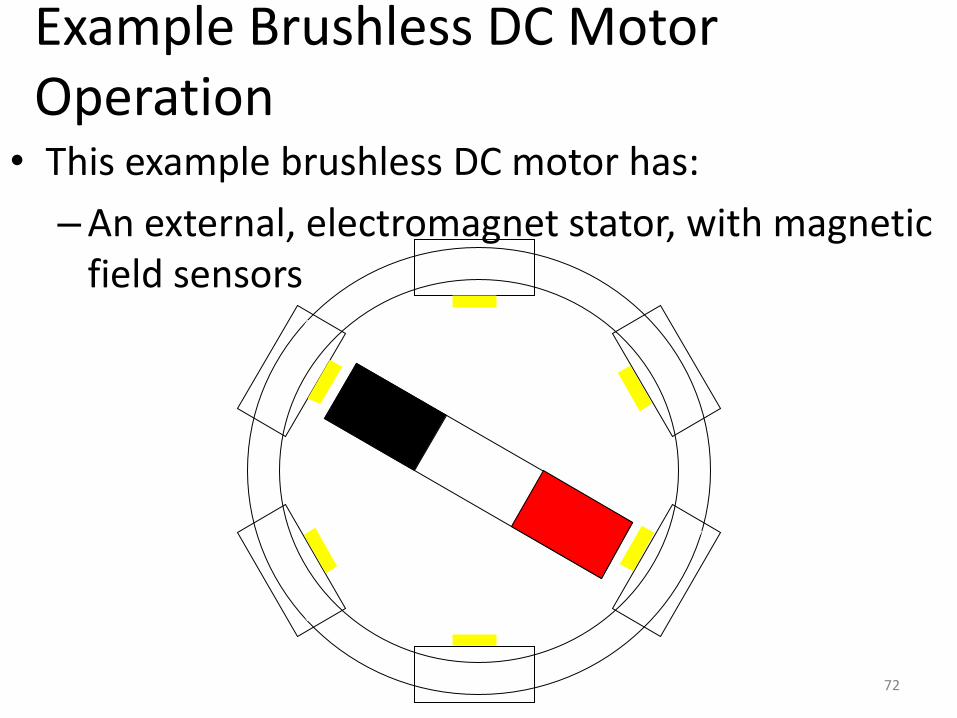
• This example brushless DC motor has:
–An external, electromagnet stator, with magnetic field sensors
Example Brushless DC Motor Operation
72
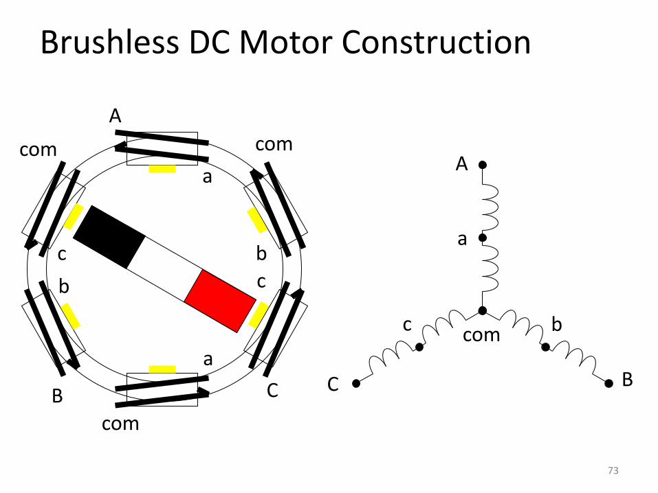
Brushless DC Motor Construction
A
a
a
com
com
b
b
B
com
cc
C
A
a
b
B
c
C
com
73
A
a
b
B
c
C
com
A
a
a
com
com
b
b
B
com
cc
C
1
Brushless DC Motor Operation
74
A
a
b
B
c
C
com
A
a
a
com
com
b
b
B
com
cc
C
2
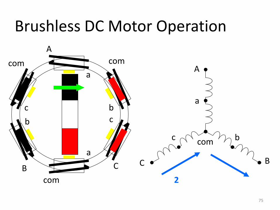
Brushless DC Motor Operation
75

A
a
b
B
c
C
com
A
a
a
com
com
b
b
B
com
cc
C
3
Brushless DC Motor Operation
76
A
a
b
B
c
C
com
A
a
a
com
com
b
b
B
com
cc
C
4
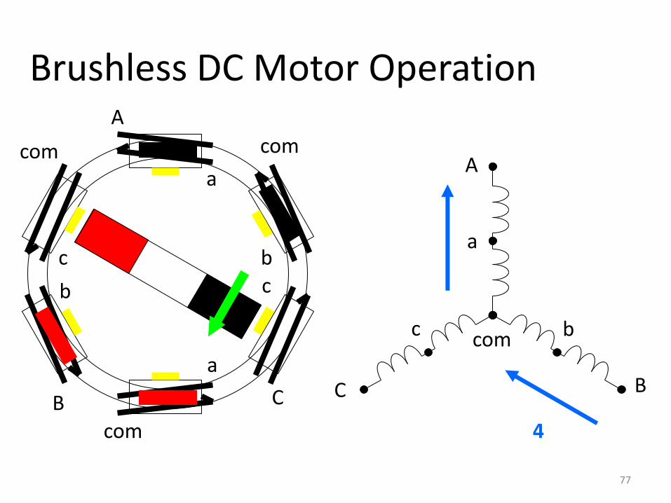
Brushless DC Motor Operation
77
A
a
b
B
c
C
com
A
a
a
com
com
b
b
B
com
cc
C
5
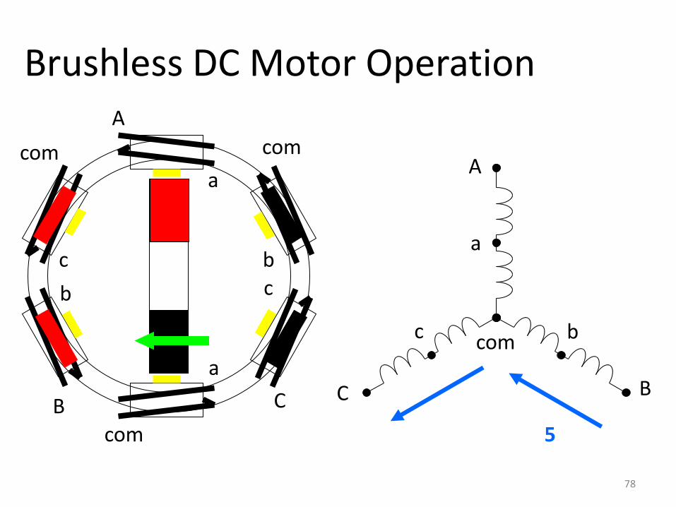
Brushless DC Motor Operation
78

A
a
b
B
c
C
com
A
a
a
com
com
b
b
B
com
cc
C
6
Brushless DC Motor Operation
79

A
a
b
B
c
C
com
A
a
a
com
com
b
b
B
com
cc
C
1
Brushless DC Motor Operation
80

Advantages:
+High efficiency
+High reliability
+Low EMI
+Good speed control
Disadvantages:
May be more expensive than "brushed" DC motors
More complex and expensive drive circuit than "brushed" DC motors
81
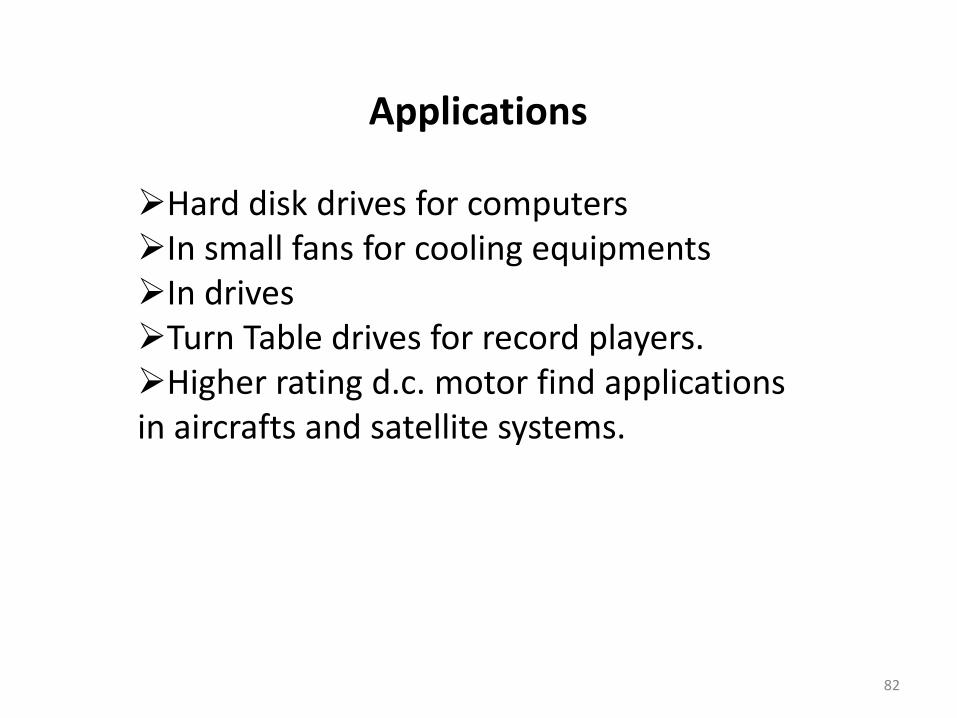
Applications
Hard disk drives for computersIn small fans for cooling equipmentsIn drivesTurn Table drives for record players.Higher rating d.c. motor find applications in aircrafts and satellite systems.
82
83


![Presentación1 sardina-para-pasta-d-e-tallartines -_5..5555[1]](https://img.pdfslide.net/doc/110x75/58829d921a28ab92618b56bf/presentacion1-sardina-para-pasta-d-e-tallartines-555551.jpg)


![Trabajo dia _de__amor_y_amistad[1]_5](https://img.pdfslide.net/doc/110x75/558c011ed8b42a1a1d8b4774/trabajo-dia-deamoryamistad15-558c1fe50b43a.jpg)