Embed Size (px)
Citation preview
Govt. of BiharDepartment of Science & Technology
Government Polytechnic Vaishali
PRODUCTION PROCESSSemester-IV (Mechanical Engineering)
Unit -3.1
MILLING
by
Prof. Jitendra KumarLecturer ,Department of Mechanical Engineering
G.P. Vaishali,Bihar-844118
CONTENTS
POWERPOINT PRESENTATION
NOTES
EXAMPLES
ASSIGNMENT

Learning Objectives
Students will be able to:
➢Understand the Milling➢ Types of Milling➢Terminology used for milling➢Methods of milling operations
Milling
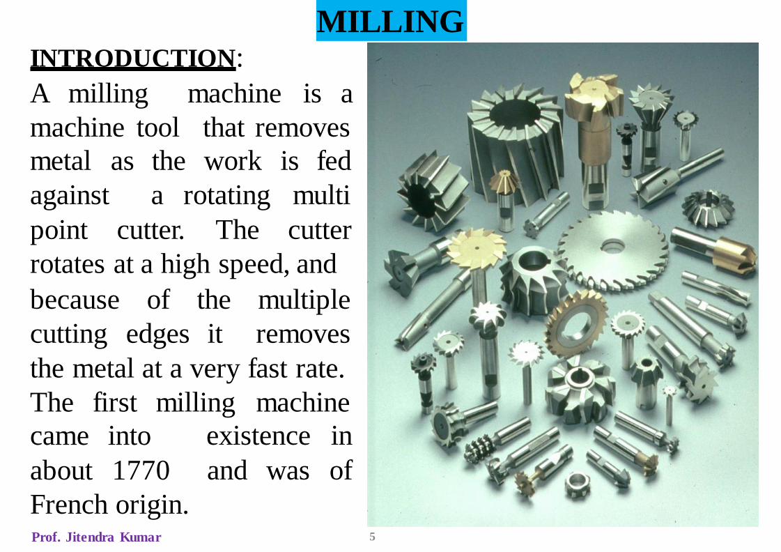
MILLINGINTRODUCTION:
A milling
machine tool
machine is a
that removes
metal as the work is fed
rotatingagainst a
point
multi
cutter. The cutter
rotates at a high speed, and
because of the
cutting edges it
multiple
removes
the metal at a very fast rate.
The first milling machine
existence in
and was of
came into
about 1770
French origin.Prof. Jitendra Kumar 5
Spindle Speed of Revolution. Spindle speed of revolution determines the velocity of cutting edge relative to the workpiece, namely, cutting speed. Since cutting speed has the great effect on tool life, the selection of cutting speed relates to the durability of tool closely. Too low or too high cutting speed will cause the tool life to decline dramatically. Meanwhile, in the milling of thin-walled workpiece, spindle speed of revolution has a significant effect on the stability of cutting. Therefore, the spindle speed of revolution should be selected discreetly in milling process.Cutting Depth and Cutting Width. Cutting depth and cutting width are restricted by spindle power, transmission power of machine tool, material type, tool parameters, coolant, machining procedure, and the stiffness of machine tool-tool-workpiece system. And, they have a great effect on tool life. Therefore, they should be selected reasonably according to machining quality, machining efficiency, and machining procedure. Generally, machining efficiency is the first goal in roughing machining, so a larger cutting depth and cutting width should be selected. Quality of workpiece surface is the main goal in finishing machining, so a less cutting depth and cutting width should be selected.Feed Rate. Feed rate is the velocity of feed move of the cutting tool relative to workpiece in milling process. Generally, linear feed rate is adopted in practical production and it is defined as feed per minute. The feed rate of milling will affect the machining accuracy, surface quality, deformation of the workpiece, and tool life directly. And it is also restricted by tool parameters, workpiece material, tool path, stiffness of machine tool, and performance of feed system. In machining process, the feed rate of milling is selected according to part material, geometry features, quality requirements, and the capability of machine tool
Cutting Parameters
Prof. Jitendra Kumar
7
TYPES1. Column & knee type: Most commonly used for
general shop work. The table is mounted on the knee
casting, which in-turn is mounted on the vertical slides of
the main column. The knee is vertically adjustable on the
column, so that the table can be moved up and down to
accommodate work of various heights. The table can be
moved longitudinally and cross wise on the knee casting.
Classification of this type is based on methods of
supplying power to the table, diff. movement of the table
and diff. axis of rotation of the main spindle.
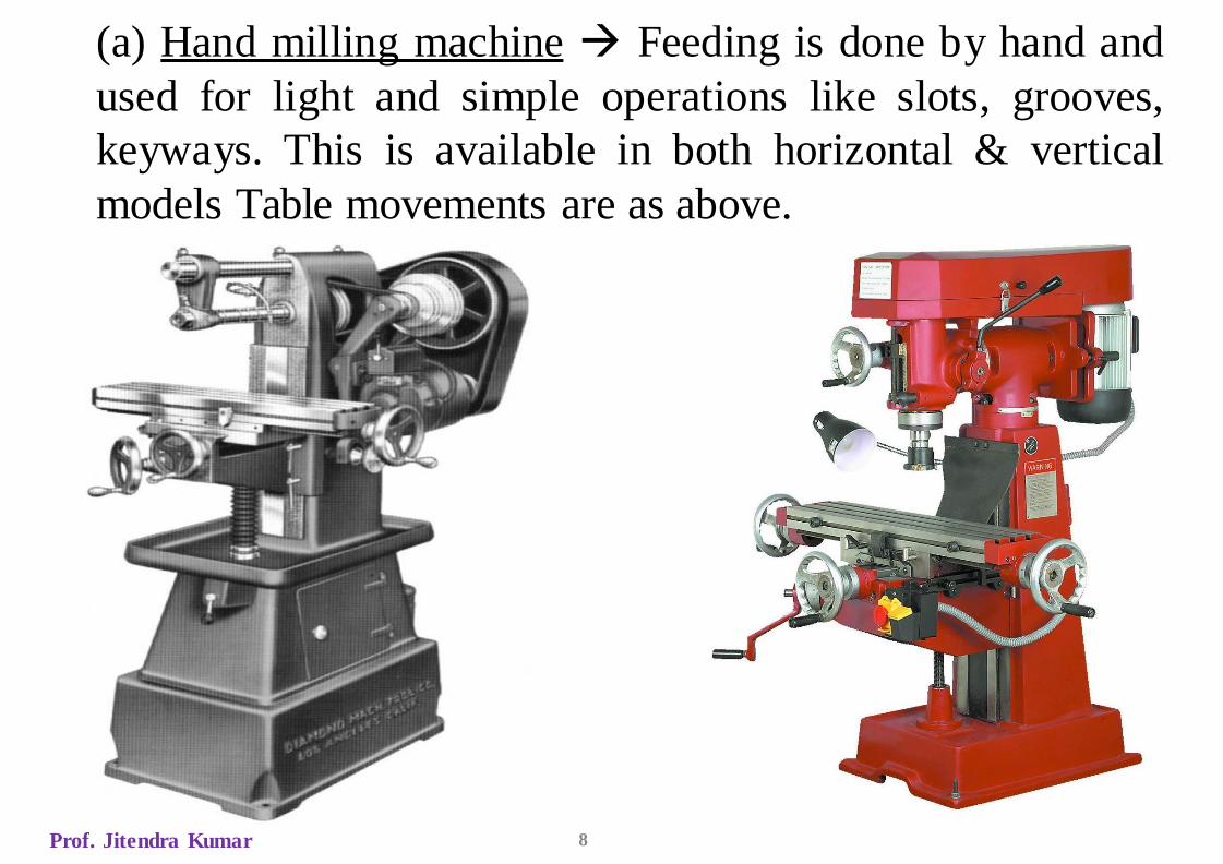
(a) Hand milling machine → Feeding is done by hand and
used for light and simple operations like slots, grooves,
keyways. This is available in both horizontal & vertical
models Table movements are as above.
Prof. Jitendra Kumar 8
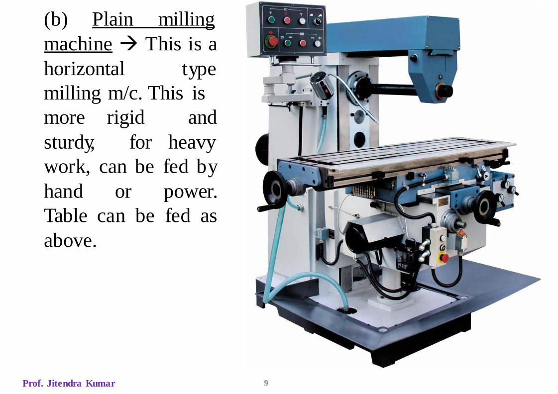
(b) Plain milling
machine → This is a
horizontal type
milling m/c. This is
more
sturdy,
rigid
for
and
heavy
work, can be fed by
hand or power.
Table can be fed as
above.
Prof. Jitendra Kumar 9
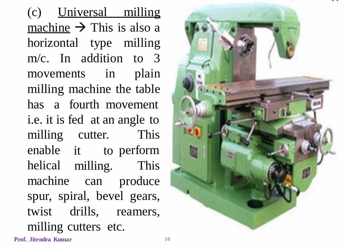
(c) Universal milling
machine → This is also a
horizontal type milling
m/c. In addition to 3
movements in plain
milling machine the table
has a fourth movement
i.e. it is fed at an angle to
cutter.milling
enable
helical
machine
it to
milling.
can
This
perform
This
produce
spur, spiral, bevel gears,
twist drills, reamers,
milling cutters etc.Prof. Jitendra Kumar 10

(d) Omniversal milling
machine → This is a
horizontal type milling
m/c. The extra
movement is the
fifth
table
can be tilted in vertical
swivel arrangement
plane by providing a
at
the knee. This enables
milling in any plane.
Taper spiral groves in
reamers, bevel gears etc
can be done.
Prof. Jitendra Kumar 11

Prof. Jitendra Kumar 12
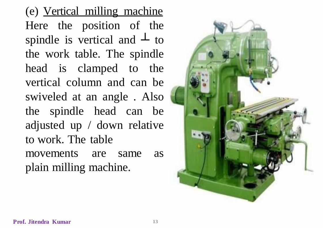
(e) Vertical milling machine
Here the position of the
spindle is vertical and ┴ to
the work table. The spindle
head is clamped to the
vertical column and can be
swiveled at an angle . Also
the spindle head can be
adjusted up / down relative
to work. The table
movements are same as
plain milling machine.
Prof. Jitendra Kumar 13
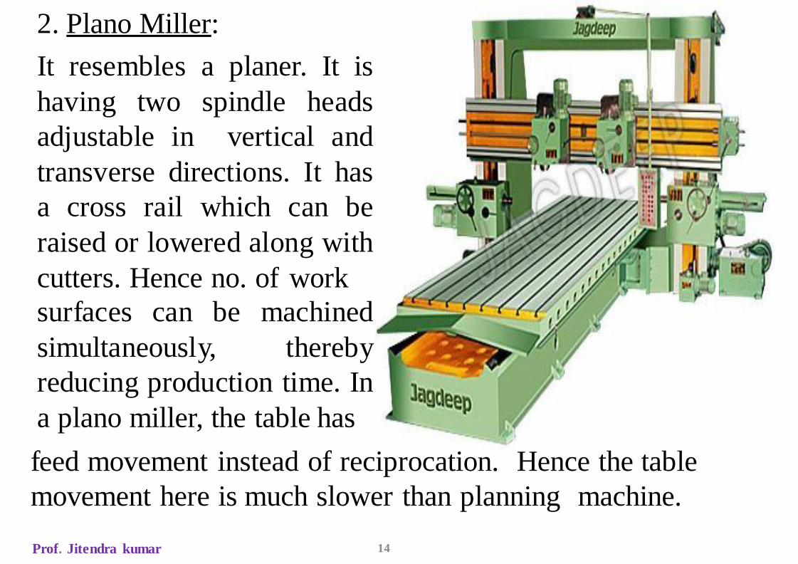
2. Plano Miller:
It resembles a planer. It is
having two spindle heads
adjustable in vertical and
transverse directions. It has
a cross rail which can be
raised or lowered along with
cutters. Hence no. of work
surfaces can be machined
simultaneously, thereby
reducing production time. In
a plano miller, the table has
feed movement instead of reciprocation. Hence the table
movement here is much slower than planning machine.
Prof. Jitendra kumar 14
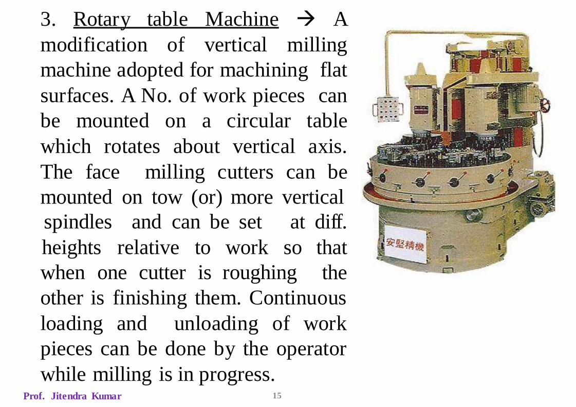
3. Rotary table Machine → A
modification of vertical milling
machine adopted for machining flat
surfaces. A No. of work pieces can
be mounted on a circular table
which rotates about vertical axis.
The face milling cutters can be
mounted on tow (or) more vertical
when one cutter is roughing
spindles and can be set at diff.
heights relative to work so that
the
other is finishing them. Continuous
loading and unloading of work
pieces can be done by the operator
while milling is in progress.Prof. Jitendra Kumar 15
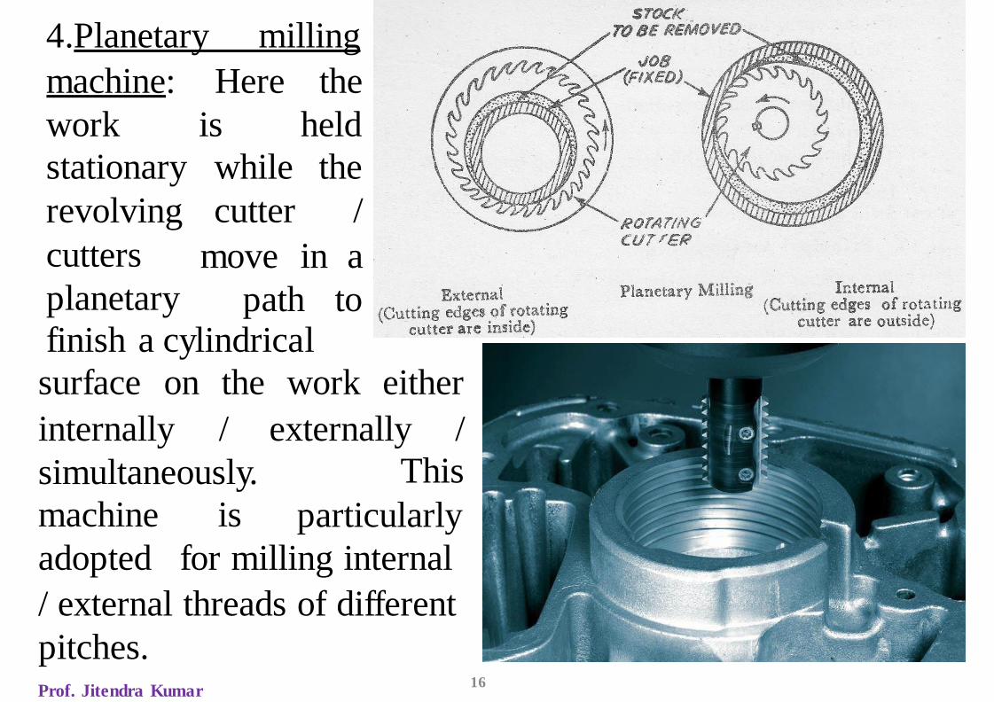
4.Planetary milling
machine:
work
Here the
is held
stationary while the
cutter /revolving
cutters
planetary
move in a
path tofinish a cylindrical
surface on the work either
Prof. Jitendra Kumar16
internally / externally /
simultaneously. This
particularlymachine is
adopted for milling internal
/ external threads of different
pitches.
Prof. Jitendra Kumar 17
5. Pantograph milling machine → It can duplicate a job by
using a pantograph mechanism which permits the size o the
work piece reproduced to be smaller than, equal to or
greater than the size of a template or model used for this
purpose. A pantograph is a mechanism that is generally
constructed of four bars or links joined in the form of
parallelogram. Pantograph machines are available in 2D or
3D models. 2-D models are used for engraving letters or
other designs, 3-D models are used for copying any shape
and contour of the work piece. The tracing stylus
is moved manually on the contour of the model to be
duplicated and the milling cutter mounted on the spindle
moves in a similar path on the work piece, reproducing the
shape of the model.
Prof. Jitendra Kumar 18
SPECIFICATIONS
1. The max. length of longitudinal, cross and vertical travel
of the table.
2. No. of spindle speeds,
3. No. of table speeds and feeds
4. Floor space required
5. Net weight required
6. Spindle nose taper (for vertical milling machine spindle
and arbors)
Prof. Jitendra Kumar 19
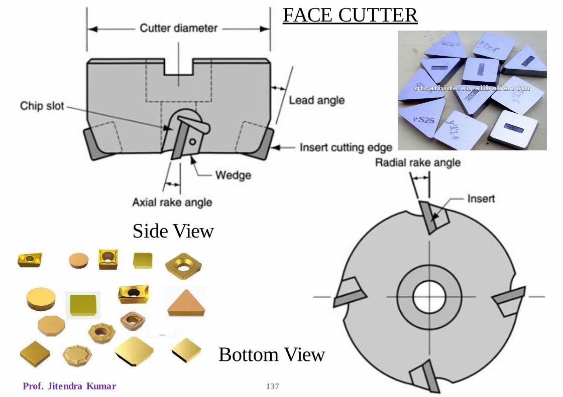
MILLING GEOMETRYPeripheral cutter: As the cutting edges are arranged radially
on the periphery the rake angle is called radial rake which is
the cutting edges angle w.r.t to the periphery of the cutter. +ve
radial rake gives better performance in peripheral milling.
Face cutter: Two rake angles are defined here.
(a)Radial rake is the cutting insert’s angle w.r.t the periphery
of the cutter
(b)Axial rake is the cutting insert’s angle w.r.t the central axis
of the cutter.
Axial Rake has significant effect on axial force and thrust
applied to the spindle. Radial rake has major effect on
tangential and radial forces. +ve axial rake, - ve radial rake
gives best performance.
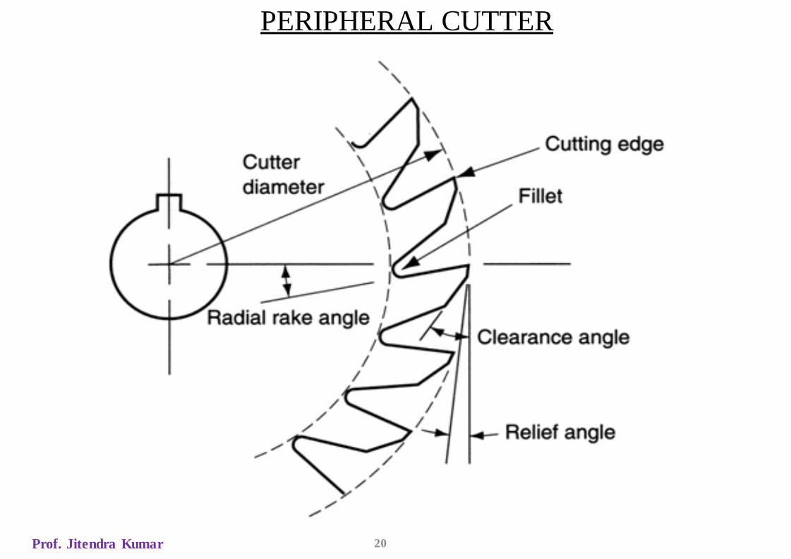
PERIPHERAL CUTTER
Prof. Jitendra Kumar 20
Prof. Jitendra Kumar 22
METHODS OF MILLING1. Peripheral Milling: It is the operation performed by a
milling cutter to produce a machined surface parallel to the
axis of rotation of the cutter. Here the cutting force is not
uniform throughout the length of cut by each tooth. Due to
this reason, a shock is developed in the mechanism of the
machine that leads to a vibration. The quality of surface
generated and the shape of the chip formed is dependent
upon the rotation of the cutter relative to the direction of feed
movement of the work. According to the relative movement
between the tool and work, the peripheral milling is
classified into two types:
Prof. Jitendra Kumar 23
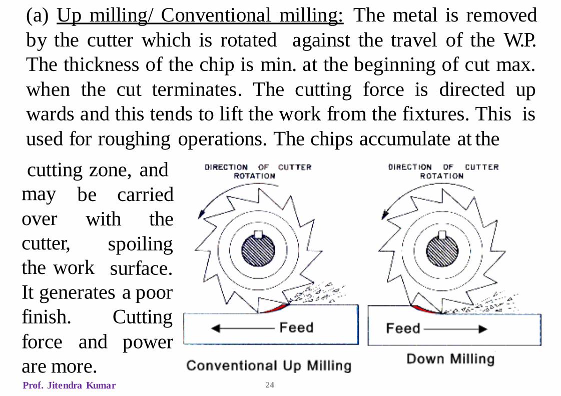
(a) Up milling/ Conventional milling: The metal is removed
by the cutter which is rotated against the travel of the W.P.
The thickness of the chip is min. at the beginning of cut max.
when the cut terminates. The cutting force is directed up
wards and this tends to lift the work from the fixtures. This is
used for roughing operations. The chips accumulate at the
cutting zone, and
Prof. Jitendra Kumar 24
be carried
with the
may
over
cutter,
the work
spoiling
surface.
It generates a poor
finish.
force and
Cutting
power
are more.
Prof. Jitendra kumar 141
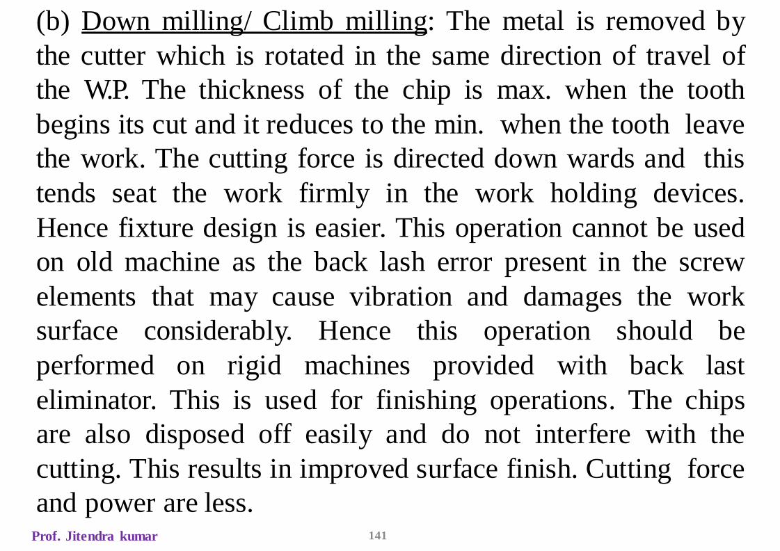
(b) Down milling/ Climb milling: The metal is removed by
the cutter which is rotated in the same direction of travel of
the W.P. The thickness of the chip is max. when the tooth
begins its cut and it reduces to the min. when the tooth leave
the work. The cutting force is directed down wards and this
tends seat the work firmly in the work holding devices.
Hence fixture design is easier. This operation cannot be used
on old machine as the back lash error present in the screw
elements that may cause vibration and damages the work
surface considerably. Hence this operation should be
performed on rigid machines provided with back last
eliminator. This is used for finishing operations. The chips
are also disposed off easily and do not interfere with the
cutting. This results in improved surface finish. Cutting force
and power are less.
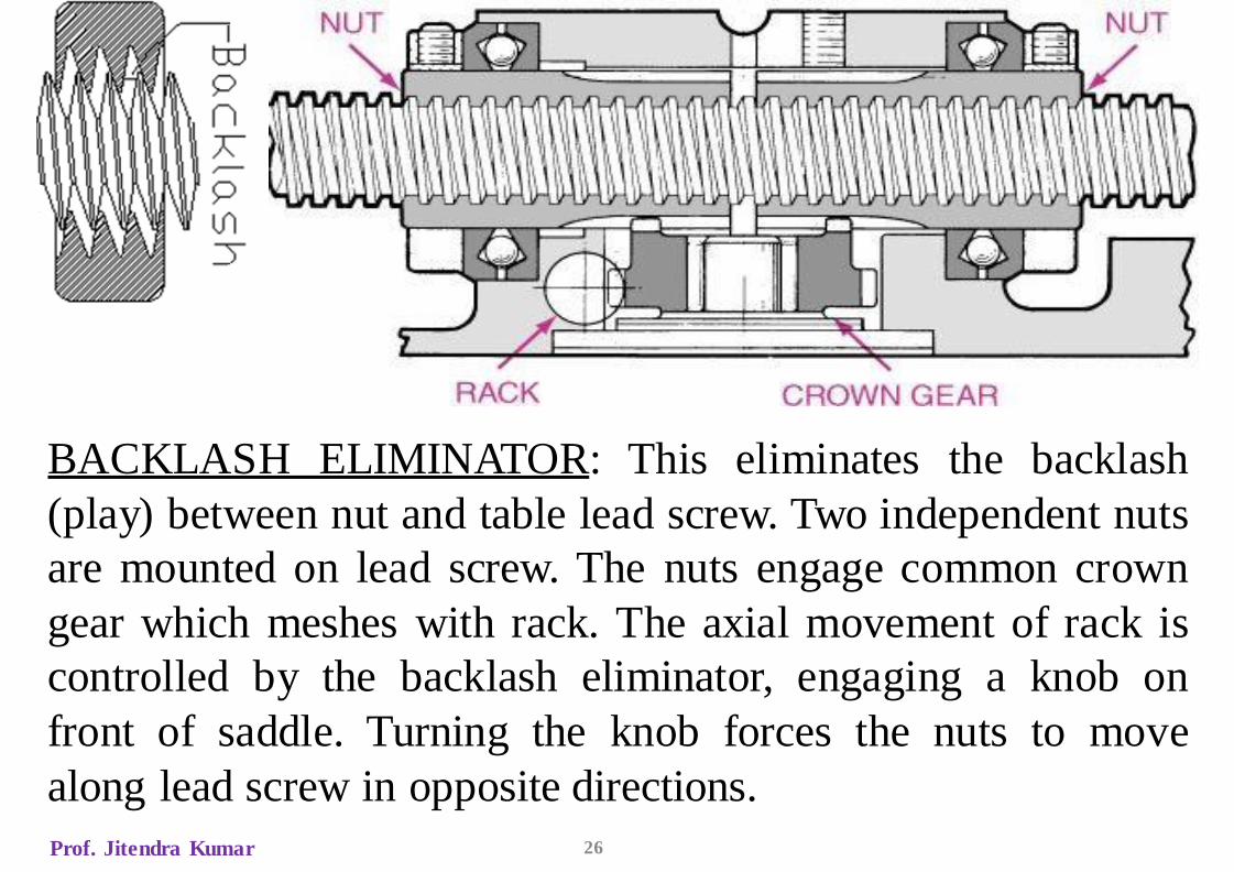
BACKLASH ELIMINATOR: This eliminates the backlash
(play) between nut and table lead screw. Two independent nuts
are mounted on lead screw. The nuts engage common crown
gear which meshes with rack. The axial movement of rack is
controlled by the backlash eliminator, engaging a knob on
front of saddle. Turning the knob forces the nuts to move
along lead screw in opposite directions.
Prof. Jitendra Kumar 26
Advantages of Down Milling
1. Suited to machine thin and hard-to-hold parts since the workpiece is
forced against the table or holding device by the cutter.
2. Work need not be clamped as tightly.
3. Consistent parallelism and size may be maintained, particularly on thin
parts.
4. It may be used where breakout at the edge of the workpiece could not be
tolerated.
5. It requires upto 20% less power to cut by this method.
6. It may be used when cutting off stock or when milling deep, thin slots.
Disadvantages of Down Milling
1.It cannot be used unless the machine has a backlash eliminator
and the table jibs have been tightened.
2.It cannot be used for machining castings or hot rolled steel,
since the hard outer scale will damage the cutter.
Prof. JitendraKumar 29
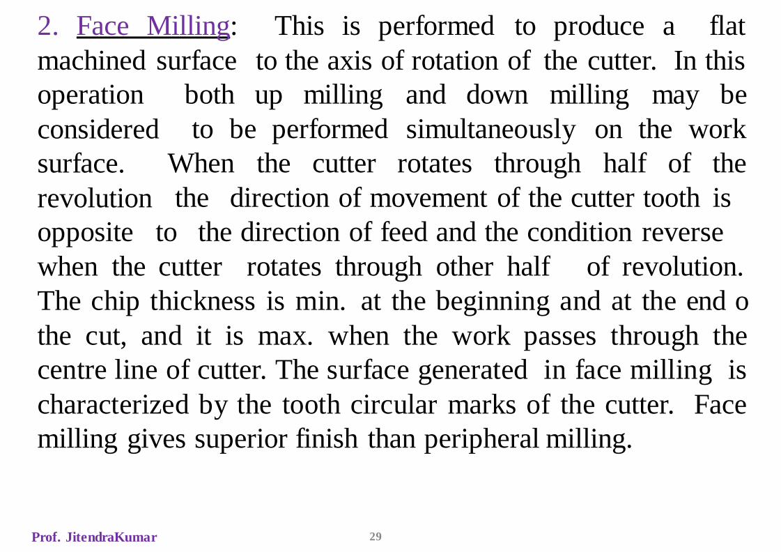
2. Face Milling: This is performed to produce a flat
machined surface to the axis of rotation of the cutter. In this
both up milling and down milling may be
to be performed simultaneously on the work
When the cutter rotates through half of the
operation
considered
surface.
revolution the direction of movement of the cutter tooth is
opposite to the direction of feed and the condition reverse
when the cutter rotates through other half of revolution.
The chip thickness is min. at the beginning and at the end o
the cut, and it is max. when the work passes through the
centre line of cutter. The surface generated in face milling is
characterized by the tooth circular marks of the cutter. Face
milling gives superior finish than peripheral milling.
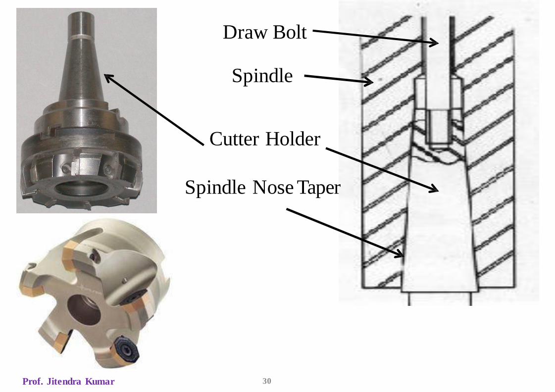
Draw Bolt
Spindle
Cutter Holder
Spindle Nose Taper
Prof. Jitendra Kumar 30
Prof. Jitendra kumar 31
3. End Milling: It is a combination of peripheral and face
milling operations. The cutter has cutting edges both on the
end face and on the periphery. The cutting characteristics
may be of peripheral or face milling type according to the
particular cutter surface used. When end cutting edges are
only used to remove metal, the direction of rotation and
direction of cutters should be same. When peripheral cutting
edges are used, they must be opposite to each other.
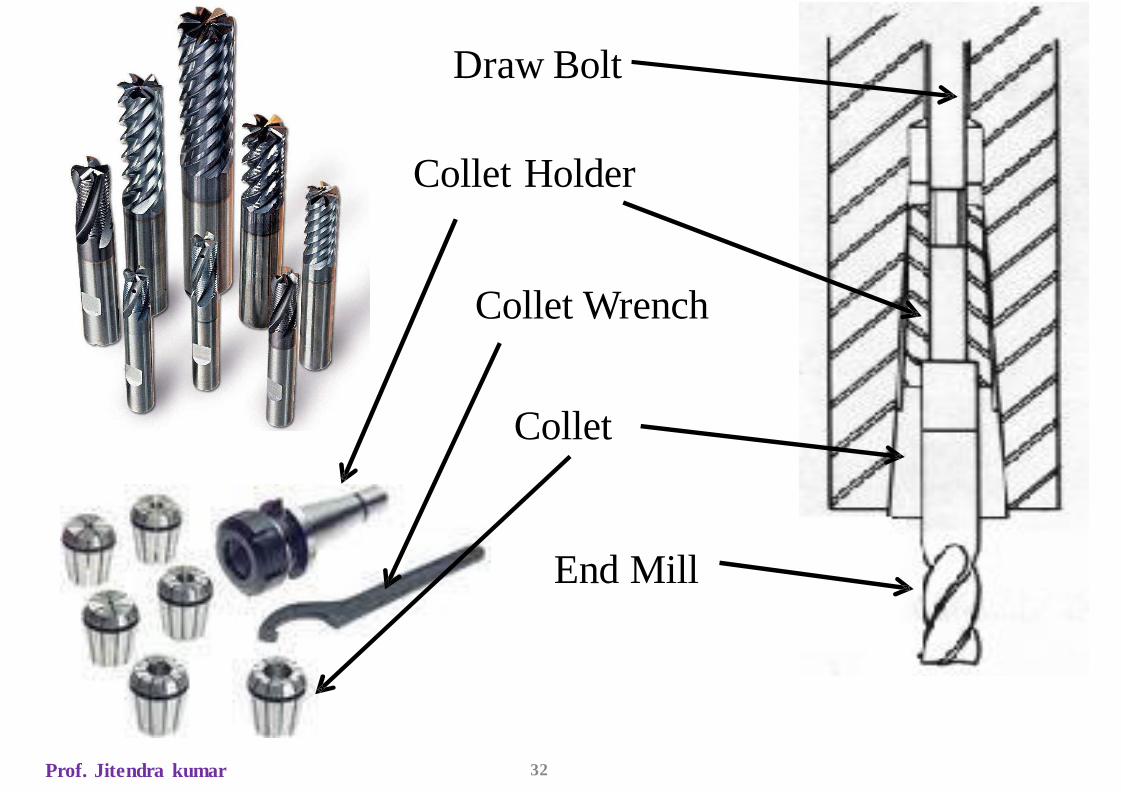
Draw Bolt
Collet Holder
Collet Wrench
Collet
End Mill
Prof. Jitendra kumar 32
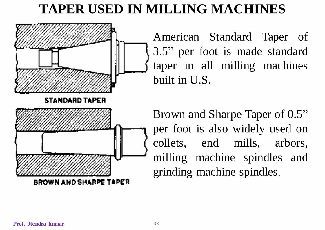
TAPER USED IN MILLING MACHINES
Prof. Jtendra kumar 33
American Standard Taper of
3.5” per foot is made standard
taper in all milling machines
built in U.S.
Brown and Sharpe Taper of 0.5”
per foot is also widely used on
collets, end mills, arbors,
milling machine spindles and
grinding machine spindles.
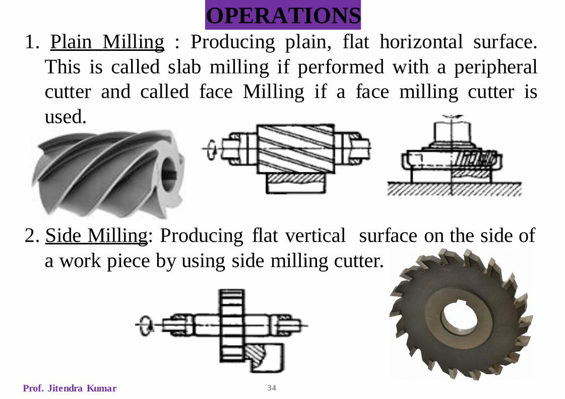
OPERATIONS1. Plain Milling : Producing plain, flat horizontal surface.
This is called slab milling if performed with a peripheral
cutter and called face Milling if a face milling cutter is
used.
2. Side Milling: Producing flat vertical surface on the side of
a work piece by using side milling cutter.
Prof. Jitendra Kumar 34
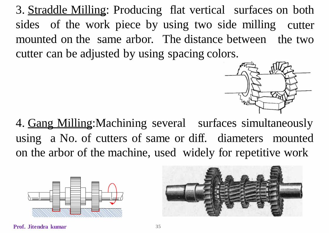
3. Straddle Milling: Producing flat vertical surfaces on both
cutter
the two
sides of the work piece by using two side milling
mounted on the same arbor. The distance between
cutter can be adjusted by using spacing colors.
4. Gang Milling:Machining several surfaces simultaneously
using a No. of cutters of same or diff. diameters mounted
on the arbor of the machine, used widely for repetitive work
Prof. Jitendra kumar 35
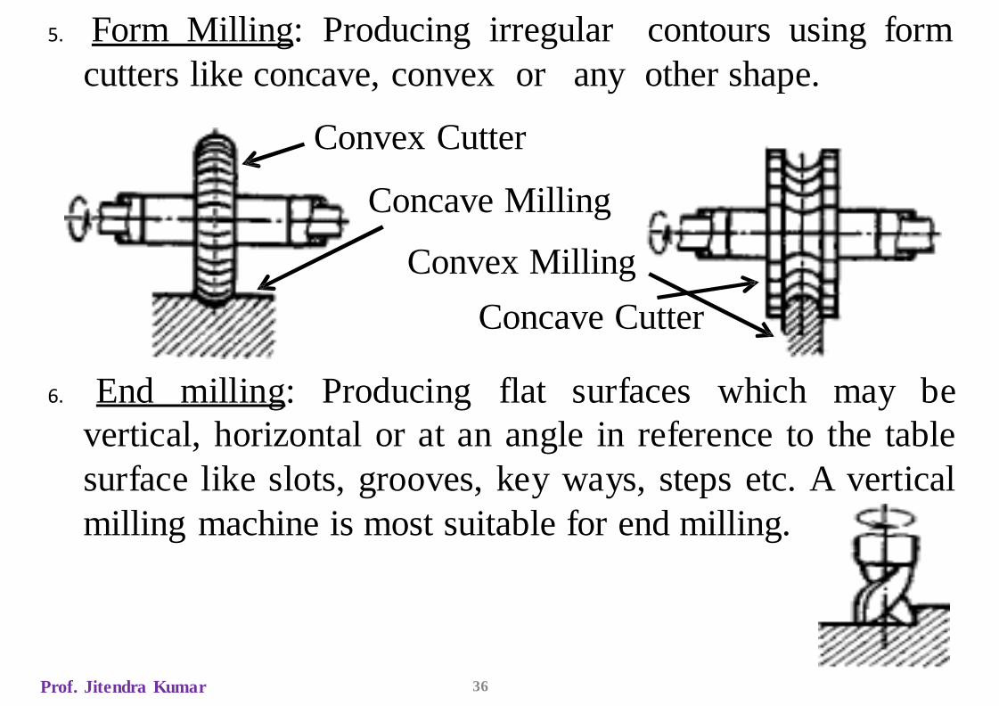
5. Form Milling: Producing irregular contours using form
cutters like concave, convex or any other shape.
Convex Cutter
Concave Milling
Convex Milling
Concave Cutter
6. End milling: Producing flat surfaces which may be
vertical, horizontal or at an angle in reference to the table
surface like slots, grooves, key ways, steps etc. A vertical
milling machine is most suitable for end milling.
Prof. Jitendra Kumar 36
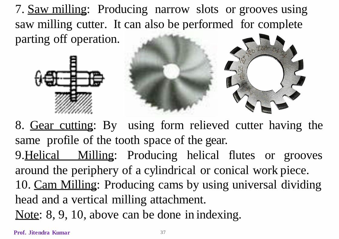
7. Saw milling: Producing narrow slots or grooves using
saw milling cutter. It can also be performed for complete
parting off operation.
8. Gear cutting: By using form relieved cutter having the
same profile of the tooth space of the gear.
9.Helical Milling: Producing helical flutes or grooves
around the periphery of a cylindrical or conical work piece.
10. Cam Milling: Producing cams by using universal dividing
head and a vertical milling attachment.
Note: 8, 9, 10, above can be done in indexing.
Prof. Jitendra Kumar 37
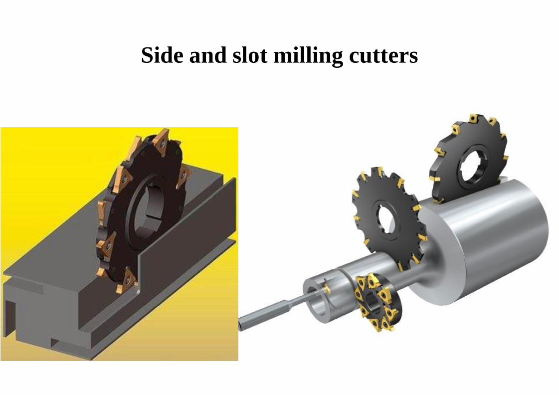
Side and slot milling cutters
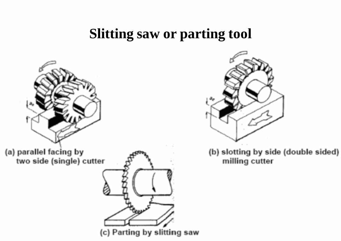
Slitting saw or parting tool
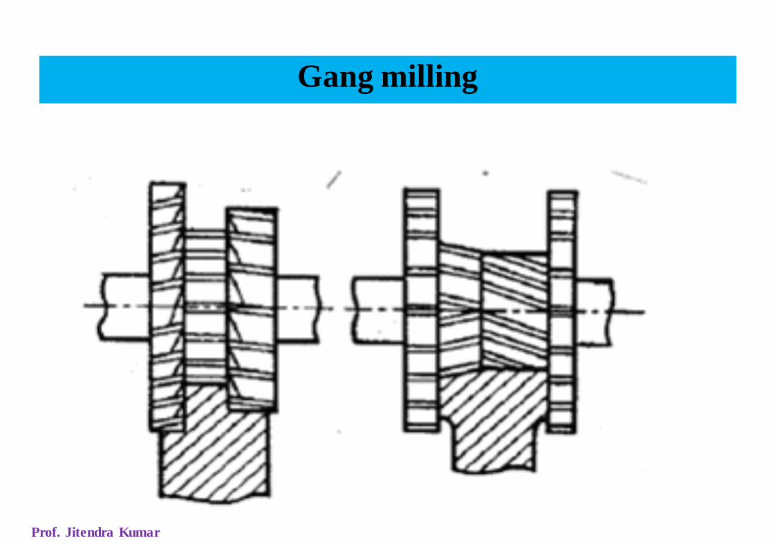
Gang milling
Prof. Jitendra Kumar

Milling Velocity
The cutting speed in milling is the surface speed of the milling
cutter.
DNV
1000
=
Prof. Jitendra Kumar
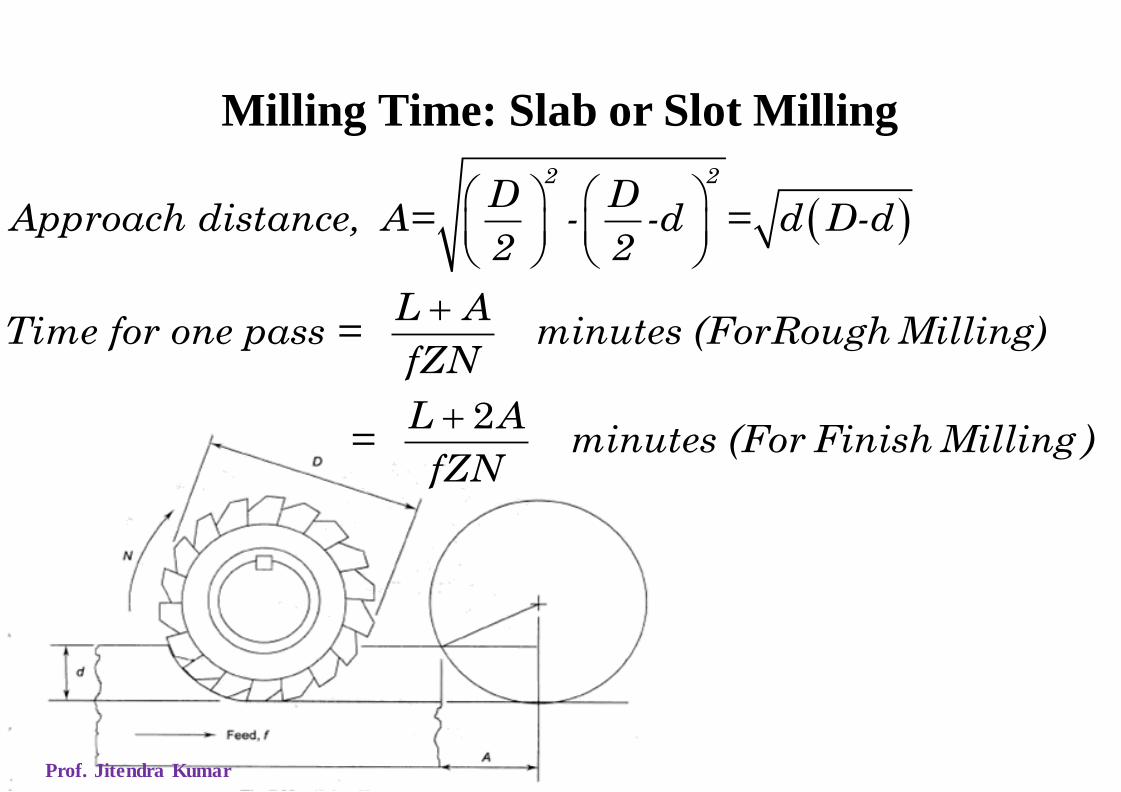
Milling Time: Slab or Slot Milling
( )2 2
D DApproach distance, A= - -d = d D-d
2 2
L ATime for one pass = minutes (ForRough Milling)
fZN
L A= minutes (For Finish Milling )
fZN
2
+
+
Prof. Jitendra Kumar

Milling Time: Face Milling
( )Approach distance, A= D D W
L ATime for one pass = minutes
fZN
2 21
2− −
+
Prof. Jitendra Kumar

MRR in Milling
Considering the parameters defined in the discussion of
speeds and feeds, etc, the MRR is given below,
Where,
MRR =
where, w = width of cut, d = depth of cutw d F
Prof. Jitendra Kumar
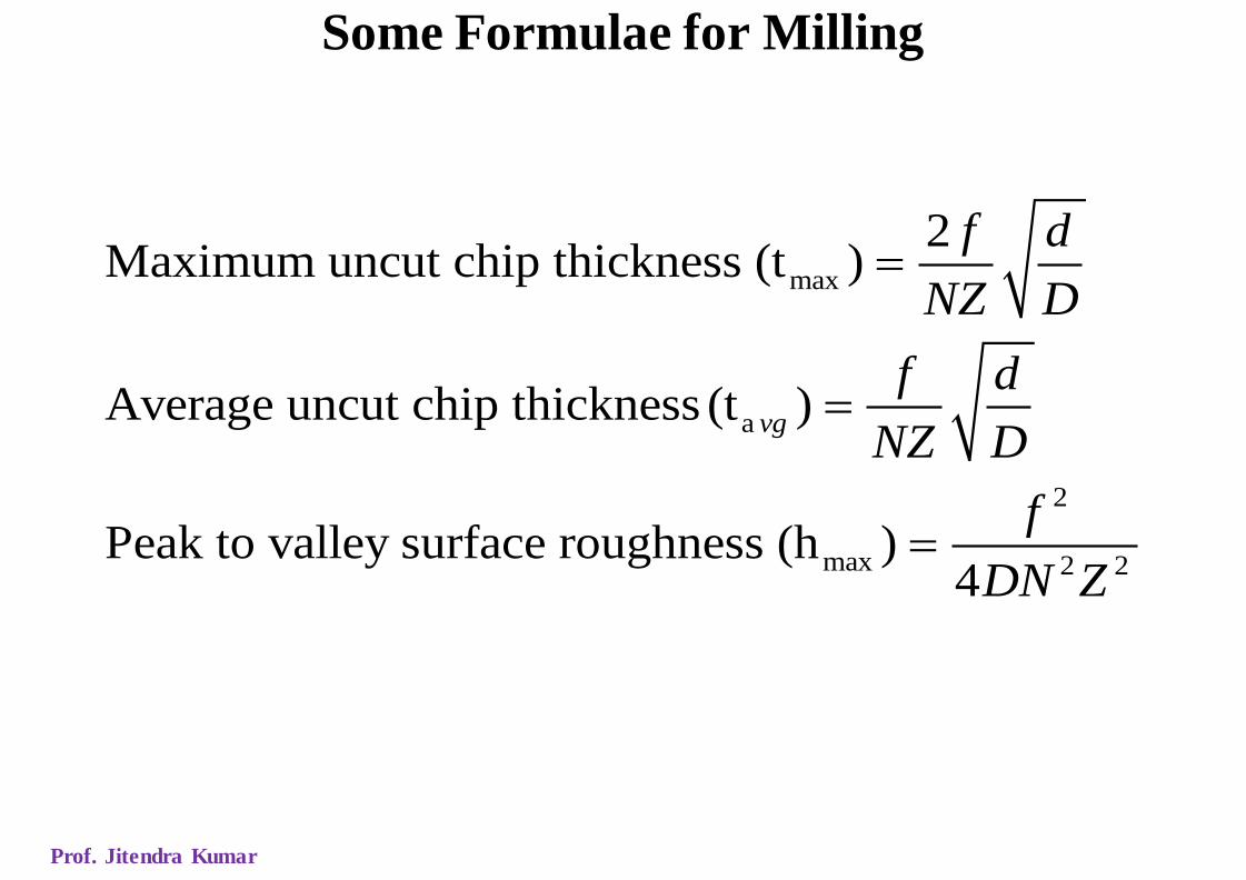
Some Formulae for Milling
max
a
2
max 2 2
2Maximum uncut chip thickness (t )
Average uncut chip thickness (t )
Peak to valley surface roughness (h )4
vg
f d
NZ D
f d
NZ D
f
DN Z
=
=
=
Prof. Jitendra Kumar
IES - 2007
What is the process of removing metal by a milling cutter
which is rotated against the direction of travel of the work
piece, called?
(a) Down milling (b) Up milling
(c) End milling (d) Face milling
Prof. Jitendra Kumar