Embed Size (px)
Citation preview
UNIT-1
VHDL Overview:
• Introduction
• Basic Language Organization
• Interface
• Architecture Body
• Logic Operators
• Concurrency
• Design Units and Libraries
VHDL is short for VHSIC (Very High Speed Integrated Circuits) Hardware Description
language. It was developed for US Department of Defense for specifying complex electronic
systems. VHDL was proposed as an IEEE standard in the year 1986. It is a hardware descriptive
language that can be used to model many digital systems down to the basic level of usage
i.e. gates, flip flops, etc. VHDL focuses upon building blocks rather than building different
components using the various gates.
Here you can build a comparator in four lines of code and the software used will simply burn the
same using a FPGA (Field Programmable Gate Array) device or other such PLD(Programmable
Logic Device).
The complexity of the digital system being modeled could vary from that of a simple gate to a
complete digital electronic system, or anything in between. The digital system can also be
described hierarchically.
The VHDL language contains statements, entities, processes functions, procedures, etc which
provide the users command over dozens of features and programming tools.
One also gets the functionality of creating test wave forms for checking whether the code written
will result into the making of a precise digital device or not.
Simulators are available for checking codes, burning codes into IC chips and loads of other
useful tasks.
How We Approach VHDL
• We‟re interested in how to use VHDL
– Not so much concerned about the theory
– Examples are used to explain details
– Constructs presented in order of applicability
• We need to learn the rules and practices
– Rules define how we must do things
• Structure, keywords, etc.
– Practices are suggestions about how to do something
• Indenting, capitalization, etc.
Practices Used by the Author
• Indenting:
• Statements embedded in other statements will be indented
• Formatting:
– Keywords: lowercase and bold
– Identifiers: uppercase and standard weight
• VHDL version:
– VHDL-87 primarily emphasized
– VHDL-93 features discussed where appropriate
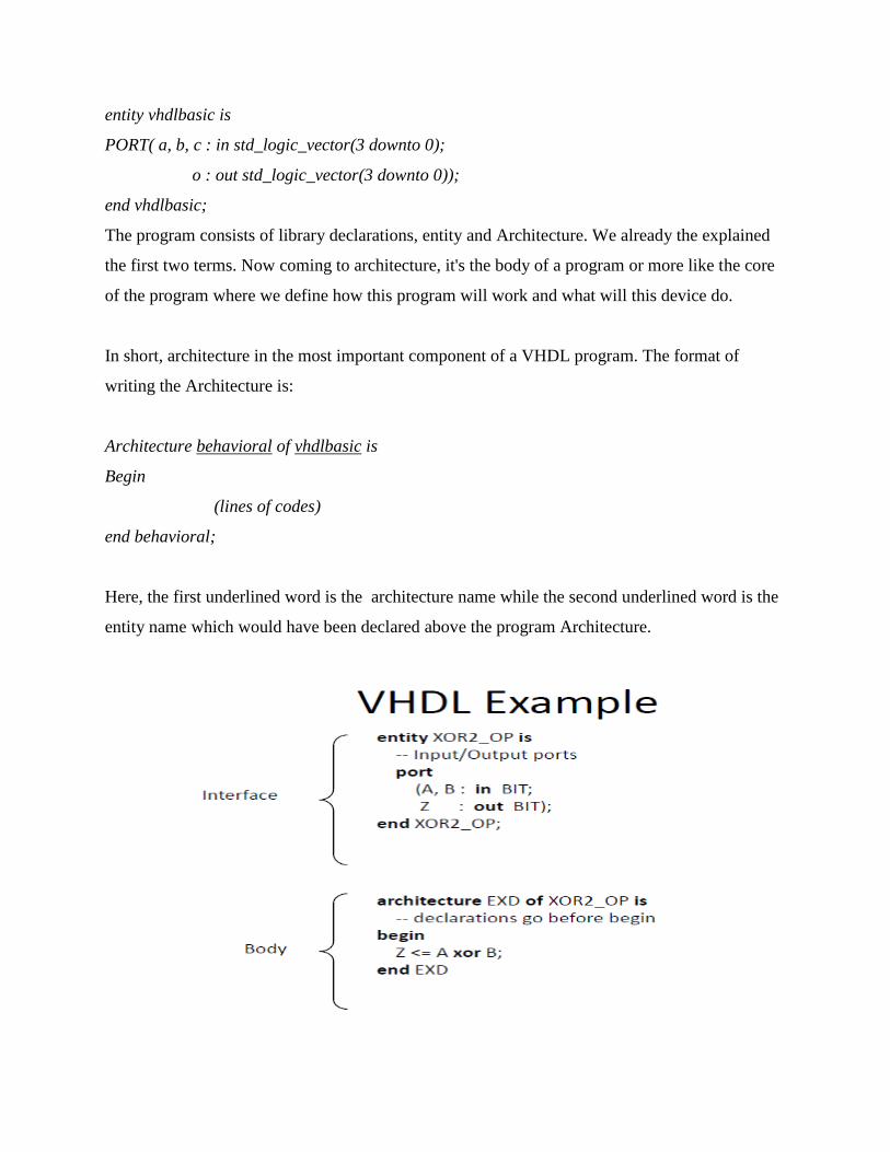
VHDL’s Organization:
• The basic VHDL model is known as a Design Entity and has two parts
– Interface - denoted by keyword entity
• defines I/O signals for the model
– Body - denoted by keyword architecture
• describes how the model works
• Comments can help document either part
– Text after two dashes is part of a comment
– Comment ends at the end of line
– Must have -- on all comment lines
There are a few terms one needs to understand and grasp so that its easier to begin coding in
VHDL.
Also, these terms form the basics of VHDL and without going through these, studying the
language will not be possible.
Some chief terms that are used at the basic level are:
1. Libraries
2. Data types
3. Signals
4. Variables
5. Entity
6. Architecture
Once you grasp these terms, you are introduced to a higher level of definition set. Some terms
are:
Process
Component
Functions
Procedures
State Diagrams
All these terms will be described in detail but let me give you a basic hint for the same.
Libraries in VHDL:
These are like books which have different chapters that impart knowledge to us. In a
similar fashion, libraries store important information, small scrapes of codes that make coding
much easier for us. The most important library that has to be used in every program is
called 'ieee' and without this, statements won't be recognized by the simulators.
Libraries are declared on top of the programs and they are mostly common for every program.
library ieee;
use ieee.std_logic_1164.all; ------->> contains nearly all the basic
statement definitions
use ieee.std_logic_arith.all; ------->> lets the user to perform
functions like datatype
conversion and stuff
use ieee.std_logic_unsigned.all; ------->> lets us perform
arithmetic operations on
std_logic datatypes by
treating them as
unsigned numbers
Declaring these three libraries will solve most problems that you will face otherwise.
There are many different Data types in VHDL but a person‟s programming approach makes it
difficult to mix up various data types. The word data type has the same meaning as it had in C. It
denotes the type or form of data.
The various data types used in VHDL are: Std_logic, Std_logic_vector, Bit, Bit_vector,
unsigned, signed, integer, etc.
The easiest operations can be performed using Std logic datatypes as all logical operations (like
And, Or, Not, Nor, etc) can be performed on these. Also, these lack the support
for arithmetic operations but the library that we defined above (ieee.std_logic_unsigned.all) will
make it happen.
Std_logic_vector is like a 1D array of C or C++. It can have any number of bits and is used
widely because it comes in handy when designing multi-bit digital devices(8 bit shift register, 4
bit binary to gray encoder, etc).
After data types, we come to the concept of signals and variables. Its simple, signals are like
permanent input/output lines that are attached to any device. These can be seen on hardware as
well. Any electronic needs supply of power or voltage and give an output, in VHDL, we have the
same scenario but we don't focus on input supply, we focus on input data and output data. All
these are in the form of signals.
Clearly, variables are temporary and their domain of existence is limited. They are declared
inside a part of a program and they perform their function and get terminated as soon as the
processing leaves that part.
So, we know a variable, we know a signal, but how do we use these and how to we declare
these?
A signal is mainly known beforehand as one can easily figure out the I/O lines in any device. So,
in VHDL coding, we set up an initial block of signal declarations along with their respective
datatypes. This block is called an entity.
The structure of an entity looks like this :
entity vhdlbasic is
PORT ( a, b, c : in std_logic;
o: out std_logic);
end vhdlbasic;
This entity is consistent with the block diagram above. Signals a, b and c are input signals while
o is the output signal and we have taken datatype as std_logic. So, each of these signals will be 1
bit in length.
If we want a 4 bit signal in place of 1 bit, we simply modify the code a bit and add some words
to modify the code as follows :
entity vhdlbasic is
PORT( a, b, c : in std_logic_vector(3 downto 0);
o : out std_logic_vector(3 downto 0));
end vhdlbasic;
The program consists of library declarations, entity and Architecture. We already the explained
the first two terms. Now coming to architecture, it's the body of a program or more like the core
of the program where we define how this program will work and what will this device do.
In short, architecture in the most important component of a VHDL program. The format of
writing the Architecture is:
Architecture behavioral of vhdlbasic is
Begin
(lines of codes)
end behavioral;
Here, the first underlined word is the architecture name while the second underlined word is the
entity name which would have been declared above the program Architecture.
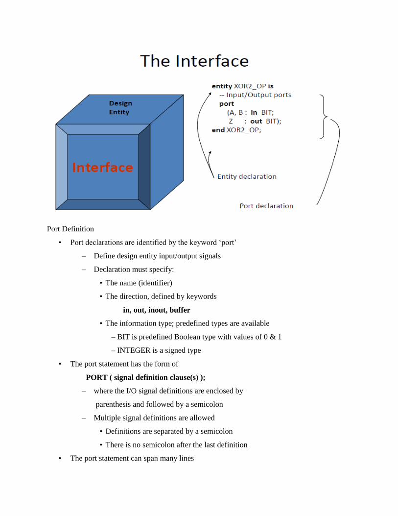
Port Definition
• Port declarations are identified by the keyword „port‟
– Define design entity input/output signals
– Declaration must specify:
• The name (identifier)
• The direction, defined by keywords
in, out, inout, buffer
• The information type; predefined types are available
– BIT is predefined Boolean type with values of 0 & 1
– INTEGER is a signed type
• The port statement has the form of
PORT ( signal definition clause(s) );
– where the I/O signal definitions are enclosed by
parenthesis and followed by a semicolon
– Multiple signal definitions are allowed
• Definitions are separated by a semicolon
• There is no semicolon after the last definition
• The port statement can span many lines
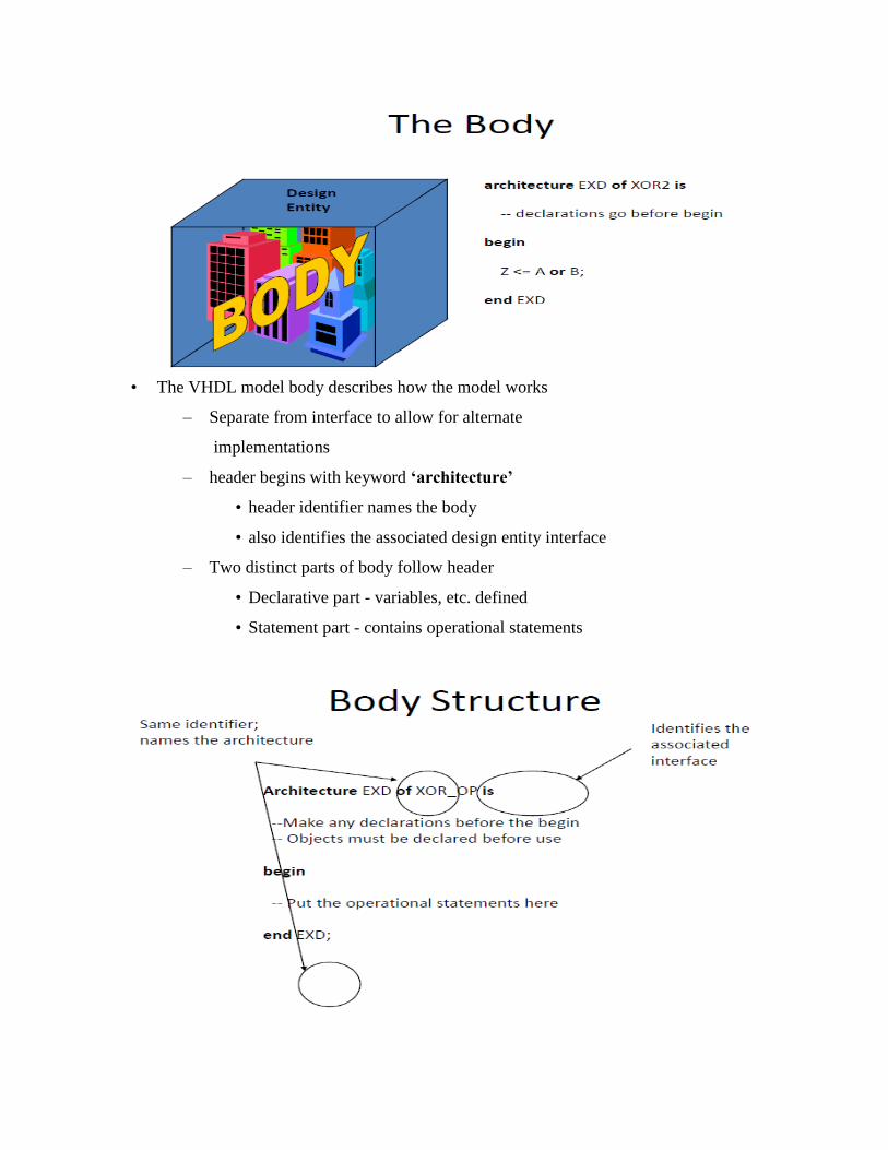
• The VHDL model body describes how the model works
– Separate from interface to allow for alternate
implementations
– header begins with keyword ‘architecture’
• header identifier names the body
• also identifies the associated design entity interface
– Two distinct parts of body follow header
• Declarative part - variables, etc. defined
• Statement part - contains operational statements
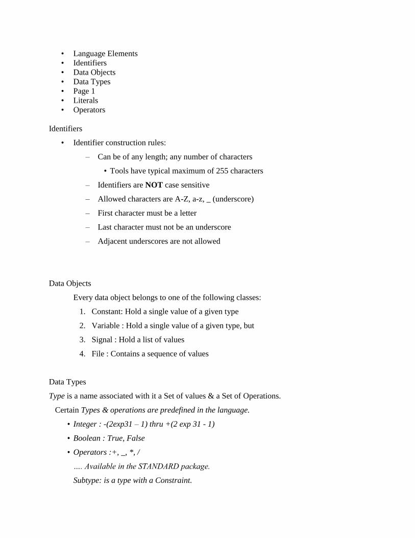
• Language Elements
• Identifiers
• Data Objects
• Data Types
• Page 1
• Literals
• Operators
Identifiers
• Identifier construction rules:
– Can be of any length; any number of characters
• Tools have typical maximum of 255 characters
– Identifiers are NOT case sensitive
– Allowed characters are A-Z, a-z, _ (underscore)
– First character must be a letter
– Last character must not be an underscore
– Adjacent underscores are not allowed
Data Objects
Every data object belongs to one of the following classes:
1. Constant: Hold a single value of a given type
2. Variable : Hold a single value of a given type, but
3. Signal : Hold a list of values
4. File : Contains a sequence of values
Data Types
Type is a name associated with it a Set of values & a Set of Operations.
Certain Types & operations are predefined in the language.
• Integer : -(2exp31 – 1) thru +(2 exp 31 - 1)
• Boolean : True, False
• Operators :+, _, *, /
…. Available in the STANDARD package.
Subtype: is a type with a Constraint.
Subtype small is INTEGER range 40 to 68;
Categorized into four categories:
• Scalar Types: Values appear in Sequential order.
• Composite Types: Composed of elements of single type (Array) or elements of different
types (Record)
• Access Types: Provides access to objects of given type
• File Types: Provide access to objects that contain a sequence of values of a given type.
• Scalar Types
Four different kinds of Scalar Types are available:
1. Enumeration:
2. Integer:
3. Physical:
4. Floating Point:
Enumeration
• Defines a set of user defined values consists of identifiers & Character literals.
type MVL is (‘U’, ‘0’, ‘1’, ‘Z’ )
type MICRO_OP is (load,store,add,sub,mul,div)
subtype ARITH_OP is MICRO_OP range add to div;
Predefined Enumeration data types
• Character : 191 Characters of ISO 8-bit character set
• Bit: „0‟, „1‟
• Boolean: FALSE, TRUE
• Severity_Level: NOTE, WARNING, ERROR, FAILURE
• File_Open_Kind: READ_MODE, WRITE_MODE, APPEND_MODE
• File_Open_Status: OPEN_OK, STATUS_ERROR, NAME_ERROR, MODE_ERROR
Integer Type
Defines a type whose set of values fall within a specified integer range.
type INDEX is range 0 to 15;
type WORD_LENGTH is range 31 downto 0;
subtype DATA_WORD is WORD_LENGTH range 15 downto 0;
Floating Point Type
Defines a type whose set of values fall within a specified real numbers range.
type real_data is range 0.0 to 31.9;
type volt is range -5.5 to -1.5;
subtype RD is real_data range 0.0 to 15.9;
Physical Type
Contains values that represent measurement of some physical quantity, like time, length, voltage,
or current.
type current is range 0 to 1E9
units
nA;
uA;
mA;
Amp;
end units;
Composite Types
Represents a collection of Values
1. Array Type: collection of Values of a single type.
2. Record Type : collection of Values that may belong to different types.
Array Type
type address_word is array (0 to 63) of BIT;
type data_word is array (7 downto 0) of std_logic;
type ROM is array (0 to 125) of Data_word;
type decode_matrix is array (positive range 15 downto 1, natural range 3 downto 0) of
std_logic;
Record Type
Composed of elements of different types or same.
type pin_type is range 0 to 10;
type module is
record
size:integer range 20 to 200;
no_inputs:pin_type;
no_outputs:pin_type;
end record;
Access Types
Values belonging to an access type are pointers to a dynamically allocated object of some other
type.
type ptr is access Module;
type FIFO is array (0 to 63, 0 to 7) of bit;
variable ptr1,ptr2 : ptr;
File Types
• Objects of file types represent files in the host environment.
• They provide a mechanism by which a VHDL design communicates with the host
environment.
type file-type-name is file of type-name;
type vectors is file of Bit_Vector;
Declarations
• Some examples
signal clock:bit;
signal gate_delay:time :=10ns;
Constant bus_width:integer :=8;
constant no_inputs : integer;
variable sum:integer range 0 to 100 :=10;
variable found, done : boolean;
File Declaration
file file-names:file-type [[open mode] is string expression];
Ex: file stimulus:text open read_mode is “d:\ece\add.txt”;
Submitted by I.LAVANYA ASSISTANT PROFESSOR III ECE-I, II DSD &DICA