Embed Size (px)
Citation preview
1
UNIT – I – Data communication and Computer networks – SITA1401
SCHOOL OF COMPUTING
DEPARTMENT OF INFORMATION TECHNOLOGY
2
DATA COMMUNICATION
Introduction to data communication - Network protocols & standards - Line configuration -
Topology -Transmission mode -Categories of networks - OSI model - Layers of OSI model -
TCP/IP Model – Transmission media - Guided media -Unguided media- Switching-Circuit
switching - Packet Switching.
1.1 INTRODUCTION
A network is a set of devices (often referred to as nodes) connected by
communication links. A node can be a computer, printer, or any other device capable
of sending and/or receiving data generated by other nodes on the network.
“Computer network’’ to mean a collection of autonomous computers
interconnected by a single technology. Two computers are said to be interconnected if
they are able to exchange information.
The connection need not be via a copper wire; fiber optics, microwaves, infrared, and
communication satellites can also be used.
Networks come in many sizes, shapes and forms, as we will see later. They are
usually connected together to make larger networks, with the Internet being the most well-
known example of a network of networks.
There is considerable confusion in the literature between a computer network and a
distributed system. The key distinction is that in a distributed system, a collection of
independent computers appears to its users as a single coherent system. Usually, it has a
single model or paradigm that it presents to the users. Often a layer of software on top of
the operating system, called middleware, is responsible for implementing this model. A
well-known example of a distributed system is the World Wide Web. It runs on top of
the Internet and presents a model in which everything looks like a document (Web page).
The effectiveness of a data communications system depends on four fundamental
characteristics: delivery, accuracy, timeliness, and jitter.
I. Delivery. The system must deliver data to the correct destination. Data must be received
by the intended device or user and only by that device or user.
2. Accuracy. The system must deliver the data accurately. Data that have been altered in
transmission and left uncorrected are unusable.
3. Timeliness. The system must deliver data in a timely manner. Data delivered
late are useless. In the case of video and audio, timely delivery means delivering
data as they are produced, in the same order that they are produced, and without
significant delay. This kind of delivery is called real-time transmission.
4. Jitter. Jitter refers to the variation in the packet arrival time. It is the uneven delay in the
delivery of audio or video packets. For example, let us assume that video packets are sent
every 30 ms. If some of the packets arrive with 30-ms delay and others with 40-ms delay,
an uneven quality in the video is the result.
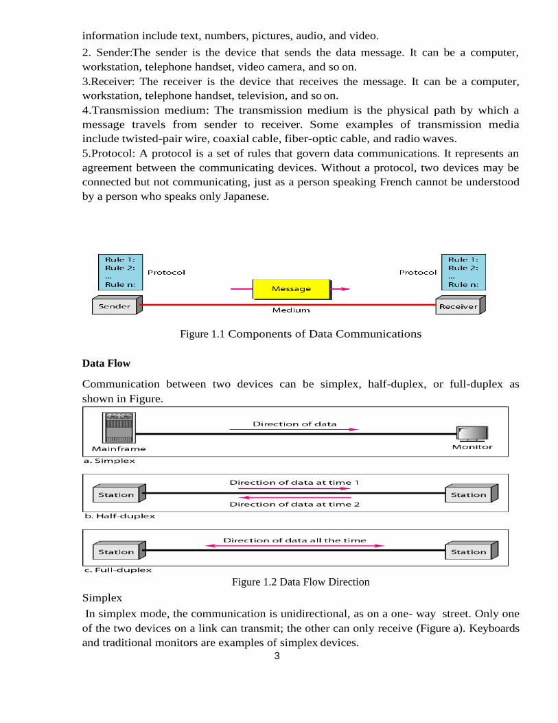
A data communications system has five components
1. Message: The message is the information (data) to be communicated. Popular forms of
3
4
information include text, numbers, pictures, audio, and video.
2. Sender:The sender is the device that sends the data message. It can be a computer,
workstation, telephone handset, video camera, and so on.
3.Receiver: The receiver is the device that receives the message. It can be a computer,
workstation, telephone handset, television, and so on.
4.Transmission medium: The transmission medium is the physical path by which a
message travels from sender to receiver. Some examples of transmission media
include twisted-pair wire, coaxial cable, fiber-optic cable, and radio waves.
5.Protocol: A protocol is a set of rules that govern data communications. It represents an
agreement between the communicating devices. Without a protocol, two devices may be
connected but not communicating, just as a person speaking French cannot be understood
by a person who speaks only Japanese.
Figure 1.1 Components of Data Communications
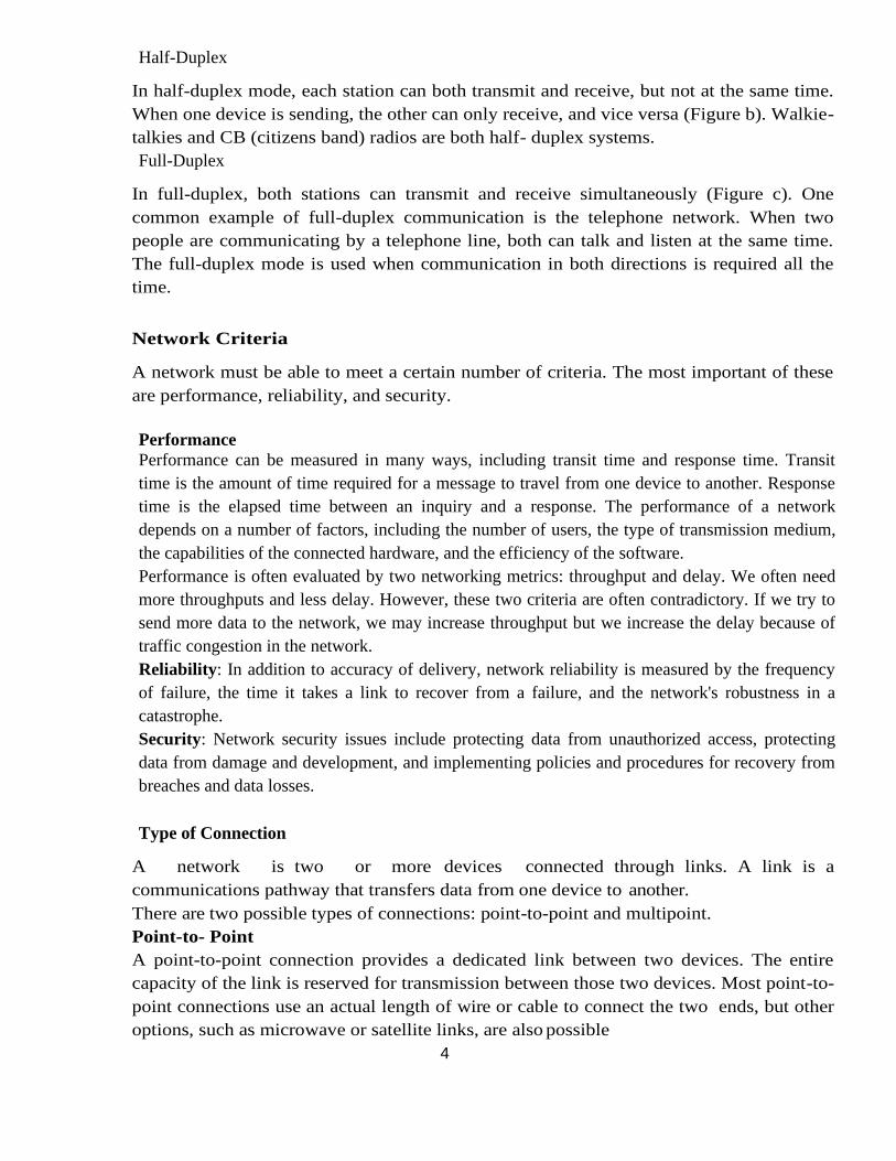
Data Flow
Communication between two devices can be simplex, half-duplex, or full-duplex as
shown in Figure.
Figure 1.2 Data Flow Direction
Simplex
In simplex mode, the communication is unidirectional, as on a one- way street. Only one
of the two devices on a link can transmit; the other can only receive (Figure a). Keyboards
and traditional monitors are examples of simplex devices.
4
Half-Duplex
In half-duplex mode, each station can both transmit and receive, but not at the same time.
When one device is sending, the other can only receive, and vice versa (Figure b). Walkie-
talkies and CB (citizens band) radios are both half- duplex systems.
Full-Duplex
In full-duplex, both stations can transmit and receive simultaneously (Figure c). One
common example of full-duplex communication is the telephone network. When two
people are communicating by a telephone line, both can talk and listen at the same time.
The full-duplex mode is used when communication in both directions is required all the
time.
Network Criteria
A network must be able to meet a certain number of criteria. The most important of these
are performance, reliability, and security.
Performance
Performance can be measured in many ways, including transit time and response time. Transit
time is the amount of time required for a message to travel from one device to another. Response
time is the elapsed time between an inquiry and a response. The performance of a network
depends on a number of factors, including the number of users, the type of transmission medium,
the capabilities of the connected hardware, and the efficiency of the software.
Performance is often evaluated by two networking metrics: throughput and delay. We often need
more throughputs and less delay. However, these two criteria are often contradictory. If we try to
send more data to the network, we may increase throughput but we increase the delay because of
traffic congestion in the network.
Reliability: In addition to accuracy of delivery, network reliability is measured by the frequency
of failure, the time it takes a link to recover from a failure, and the network's robustness in a
catastrophe.
Security: Network security issues include protecting data from unauthorized access, protecting
data from damage and development, and implementing policies and procedures for recovery from
breaches and data losses.
Type of Connection
A network is two or more devices connected through links. A link is a
communications pathway that transfers data from one device to another.
There are two possible types of connections: point-to-point and multipoint.
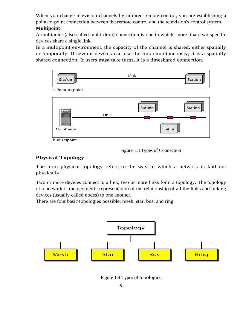
Point-to- Point
A point-to-point connection provides a dedicated link between two devices. The entire
capacity of the link is reserved for transmission between those two devices. Most point-to-
point connections use an actual length of wire or cable to connect the two ends, but other
options, such as microwave or satellite links, are also possible
5
When you change television channels by infrared remote control, you are establishing a
point-to-point connection between the remote control and the television's control system.
Multipoint
A multipoint (also called multi-drop) connection is one in which more than two specific
devices share a single link
In a multipoint environment, the capacity of the channel is shared, either spatially
or temporally. If several devices can use the link simultaneously, it is a spatially
shared connection. If users must take turns, it is a timeshared connection.
Figure 1.3 Types of Connection
Physical Topology
The term physical topology refers to the way in which a network is laid out
physically.
Two or more devices connect to a link; two or more links form a topology. The topology
of a network is the geometric representation of the relationship of all the links and linking
devices (usually called nodes) to one another.
There are four basic topologies possible: mesh, star, bus, and ring
Figure 1.4 Types of topologies
6
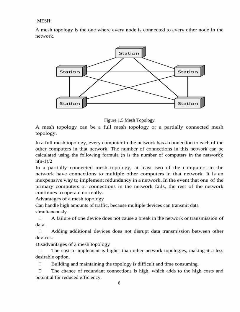
MESH:
A mesh topology is the one where every node is connected to every other node in the
network.
Figure 1.5 Mesh Topology
A mesh topology can be a full mesh topology or a partially connected mesh
topology.
In a full mesh topology, every computer in the network has a connection to each of the
other computers in that network. The number of connections in this network can be
calculated using the following formula (n is the number of computers in the network):
n(n-1)/2
In a partially connected mesh topology, at least two of the computers in the
network have connections to multiple other computers in that network. It is an
inexpensive way to implement redundancy in a network. In the event that one of the
primary computers or connections in the network fails, the rest of the network
continues to operate normally.
Advantages of a mesh topology
Can handle high amounts of traffic, because multiple devices can transmit data
simultaneously.
A failure of one device does not cause a break in the network or transmission of
data.
Adding additional devices does not disrupt data transmission between other
devices.
Disadvantages of a mesh topology
The cost to implement is higher than other network topologies, making it a less
desirable option.
Building and maintaining the topology is difficult and time consuming.
The chance of redundant connections is high, which adds to the high costs and
potential for reduced efficiency.
7
STAR:
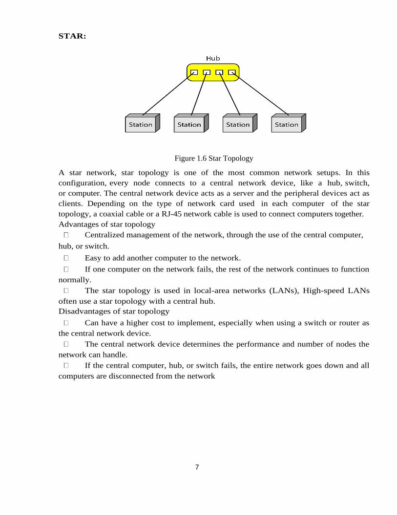
Figure 1.6 Star Topology
A star network, star topology is one of the most common network setups. In this
configuration, every node connects to a central network device, like a hub, switch,
or computer. The central network device acts as a server and the peripheral devices act as
clients. Depending on the type of network card used in each computer of the star
topology, a coaxial cable or a RJ-45 network cable is used to connect computers together.
Advantages of star topology
Centralized management of the network, through the use of the central computer,
hub, or switch.
Easy to add another computer to the network.
If one computer on the network fails, the rest of the network continues to function
normally.
The star topology is used in local-area networks (LANs), High-speed LANs
often use a star topology with a central hub.
Disadvantages of star topology
Can have a higher cost to implement, especially when using a switch or router as
the central network device.
The central network device determines the performance and number of nodes the
network can handle.
If the central computer, hub, or switch fails, the entire network goes down and all
computers are disconnected from the network
8
BUS:
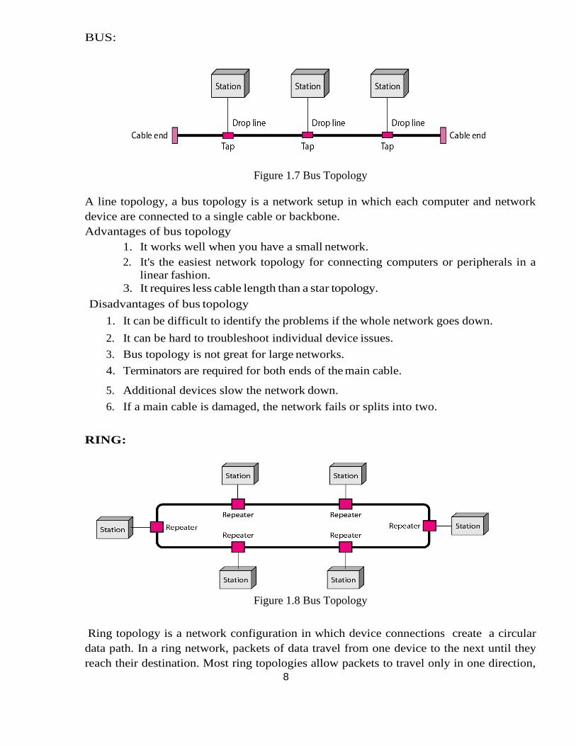
Figure 1.7 Bus Topology
A line topology, a bus topology is a network setup in which each computer and network
device are connected to a single cable or backbone.
Advantages of bus topology
1. It works well when you have a small network.
2. It's the easiest network topology for connecting computers or peripherals in a
linear fashion.
3. It requires less cable length than a star topology.
Disadvantages of bus topology
1. It can be difficult to identify the problems if the whole network goes down.
2. It can be hard to troubleshoot individual device issues.
3. Bus topology is not great for large networks.
4. Terminators are required for both ends of the main cable.
5. Additional devices slow the network down.
6. If a main cable is damaged, the network fails or splits into two.
RING:
Figure 1.8 Bus Topology
Ring topology is a network configuration in which device connections create a circular
data path. In a ring network, packets of data travel from one device to the next until they
reach their destination. Most ring topologies allow packets to travel only in one direction,
9
called a unidirectional ring network. Others permit data to move in either direction, called
bidirectional.
The major disadvantage of a ring topology is that if any individual connection in the ring
is broken, the entire network is affected.
Ring topologies may be used in either local area networks (LANs) or wide area
networks (WANs).
Advantages of ring topology
1. All data flows in one direction, reducing the chance of packet collisions.
2. A network server is not needed to control network connectivity between each
workstation.
3. Data can transfer between workstations at high speeds.
4. Additional workstations can be added without impacting performance of the
network.
Disadvantages of ring topology
1. All data being transferred over the network must pass through each workstation on
the network, which can make it slower than a star topology.
2. The entire network will be impacted if one workstation shuts down.
3. The hardware needed to connect each workstation to the network is more expensive
than Ethernet cards and hubs/switches.
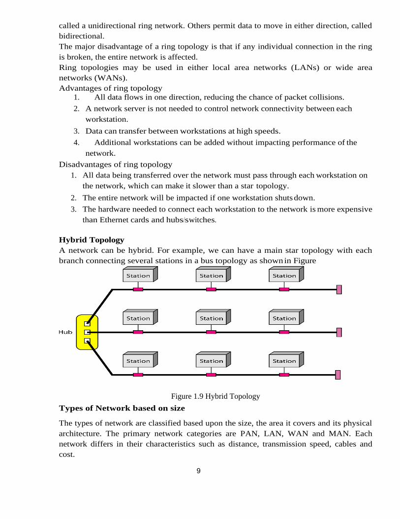
Hybrid Topology
A network can be hybrid. For example, we can have a main star topology with each
branch connecting several stations in a bus topology as shown in Figure
Figure 1.9 Hybrid Topology
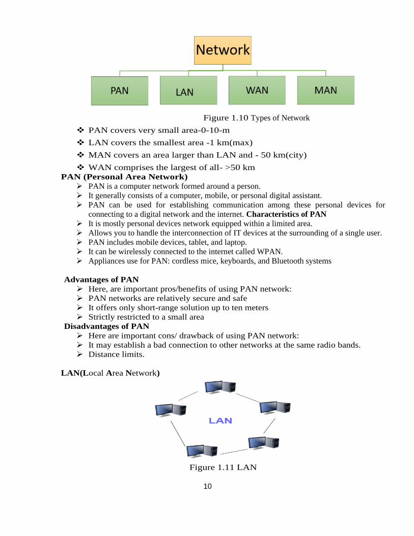
Types of Network based on size
The types of network are classified based upon the size, the area it covers and its physical
architecture. The primary network categories are PAN, LAN, WAN and MAN. Each
network differs in their characteristics such as distance, transmission speed, cables and
cost.
10
Figure 1.10 Types of Network
❖ PAN covers very small area-0-10-m
❖ LAN covers the smallest area -1 km(max)
❖ MAN covers an area larger than LAN and - 50 km(city)
❖ WAN comprises the largest of all- >50 km
PAN (Personal Area Network)
➢ PAN is a computer network formed around a person.
➢ It generally consists of a computer, mobile, or personal digital assistant.
➢ PAN can be used for establishing communication among these personal devices for
connecting to a digital network and the internet. Characteristics of PAN
➢ It is mostly personal devices network equipped within a limited area.
➢ Allows you to handle the interconnection of IT devices at the surrounding of a single user.
➢ PAN includes mobile devices, tablet, and laptop.
➢ It can be wirelessly connected to the internet called WPAN.
➢ Appliances use for PAN: cordless mice, keyboards, and Bluetooth systems
Advantages of PAN
➢ Here, are important pros/benefits of using PAN network:
➢ PAN networks are relatively secure and safe
➢ It offers only short-range solution up to ten meters
➢ Strictly restricted to a small area
Disadvantages of PAN
➢ Here are important cons/ drawback of using PAN network:
➢ It may establish a bad connection to other networks at the same radio bands.
➢ Distance limits.
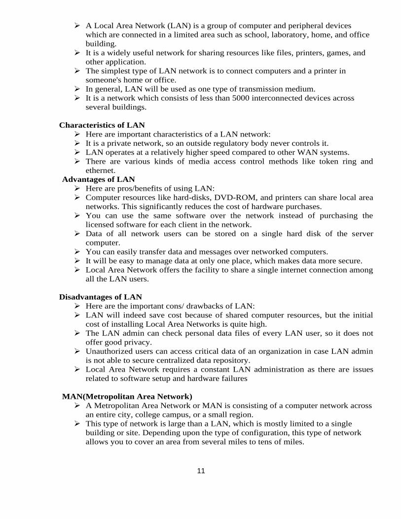
LAN(Local Area Network)
Figure 1.11 LAN
11
➢ A Local Area Network (LAN) is a group of computer and peripheral devices
which are connected in a limited area such as school, laboratory, home, and office
building.
➢ It is a widely useful network for sharing resources like files, printers, games, and
other application.
➢ The simplest type of LAN network is to connect computers and a printer in
someone's home or office.
➢ In general, LAN will be used as one type of transmission medium.
➢ It is a network which consists of less than 5000 interconnected devices across
several buildings.
Characteristics of LAN
➢ Here are important characteristics of a LAN network:
➢ It is a private network, so an outside regulatory body never controls it.
➢ LAN operates at a relatively higher speed compared to other WAN systems.
➢ There are various kinds of media access control methods like token ring and
ethernet.
Advantages of LAN
➢ Here are pros/benefits of using LAN:
➢ Computer resources like hard-disks, DVD-ROM, and printers can share local area
networks. This significantly reduces the cost of hardware purchases.
➢ You can use the same software over the network instead of purchasing the
licensed software for each client in the network.
➢ Data of all network users can be stored on a single hard disk of the server
computer.
➢ You can easily transfer data and messages over networked computers.
➢ It will be easy to manage data at only one place, which makes data more secure.
➢ Local Area Network offers the facility to share a single internet connection among
all the LAN users.
Disadvantages of LAN
➢ Here are the important cons/ drawbacks of LAN:
➢ LAN will indeed save cost because of shared computer resources, but the initial
cost of installing Local Area Networks is quite high.
➢ The LAN admin can check personal data files of every LAN user, so it does not
offer good privacy.
➢ Unauthorized users can access critical data of an organization in case LAN admin
is not able to secure centralized data repository.
➢ Local Area Network requires a constant LAN administration as there are issues
related to software setup and hardware failures
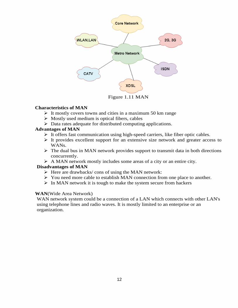
MAN(Metropolitan Area Network)
➢ A Metropolitan Area Network or MAN is consisting of a computer network across
an entire city, college campus, or a small region.
➢ This type of network is large than a LAN, which is mostly limited to a single
building or site. Depending upon the type of configuration, this type of network
allows you to cover an area from several miles to tens of miles.
12
Figure 1.11 MAN
Characteristics of MAN
➢ It mostly covers towns and cities in a maximum 50 km range
➢ Mostly used medium is optical fibers, cables
➢ Data rates adequate for distributed computing applications.
Advantages of MAN
➢ It offers fast communication using high-speed carriers, like fiber optic cables.
➢ It provides excellent support for an extensive size network and greater access to
WANs.
➢ The dual bus in MAN network provides support to transmit data in both directions
concurrently.
➢ A MAN network mostly includes some areas of a city or an entire city.
Disadvantages of MAN
➢ Here are drawbacks/ cons of using the MAN network:
➢ You need more cable to establish MAN connection from one place to another.
➢ In MAN network it is tough to make the system secure from hackers
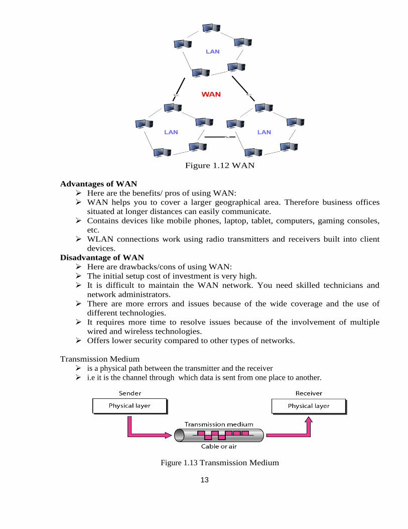
WAN(Wide Area Network)
WAN network system could be a connection of a LAN which connects with other LAN's
using telephone lines and radio waves. It is mostly limited to an enterprise or an
organization.
13
Figure 1.12 WAN
Advantages of WAN
➢ Here are the benefits/ pros of using WAN:
➢ WAN helps you to cover a larger geographical area. Therefore business offices
situated at longer distances can easily communicate.
➢ Contains devices like mobile phones, laptop, tablet, computers, gaming consoles,
etc.
➢ WLAN connections work using radio transmitters and receivers built into client
devices.
Disadvantage of WAN
➢ Here are drawbacks/cons of using WAN:
➢ The initial setup cost of investment is very high.
➢ It is difficult to maintain the WAN network. You need skilled technicians and
network administrators.
➢ There are more errors and issues because of the wide coverage and the use of
different technologies.
➢ It requires more time to resolve issues because of the involvement of multiple
wired and wireless technologies.
➢ Offers lower security compared to other types of networks.
Transmission Medium
➢ is a physical path between the transmitter and the receiver
➢ i.e it is the channel through which data is sent from one place to another.
Figure 1.13 Transmission Medium
14
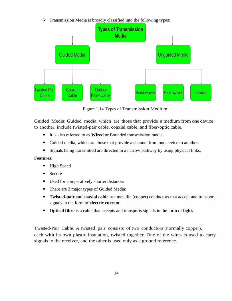
➢ Transmission Media is broadly classified into the following types:
Figure 1.14 Types of Transmission Medium
Guided Media: Guided media, which are those that provide a medium from one device
to another, include twisted-pair cable, coaxial cable, and fiber-optic cable.
It is also referred to as Wired or Bounded transmission media.
Guided media, which are those that provide a channel from one device to another.
Signals being transmitted are directed in a narrow pathway by using physical links.
Features:
High Speed
Secure
Used for comparatively shorter distances
There are 3 major types of Guided Media:
Twisted-pair and coaxial cable use metallic (copper) conductors that accept and transport
signals in the form of electric current.
Optical fibre is a cable that accepts and transports signals in the form of light.
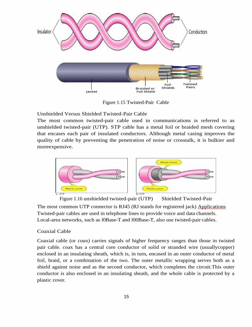
Twisted-Pair Cable: A twisted pair consists of two conductors (normally copper),
each with its own plastic insulation, twisted together. One of the wires is used to carry
signals to the receiver, and the other is used only as a ground reference.
15
Figure 1.15 Twisted-Pair Cable
Unshielded Versus Shielded Twisted-Pair Cable
The most common twisted-pair cable used in communications is referred to as
unshielded twisted-pair (UTP). STP cable has a metal foil or braided mesh covering
that encases each pair of insulated conductors. Although metal casing improves the
quality of cable by preventing the penetration of noise or crosstalk, it is bulkier and
moreexpensive.
Figure 1.16 unshielded twisted-pair (UTP) Shielded Twisted-Pair
The most common UTP connector is RJ45 (RJ stands for registered jack) Applications
Twisted-pair cables are used in telephone lines to provide voice and data channels.
Local-area networks, such as l0Base-T and l00Base-T, also use twisted-pair cables.
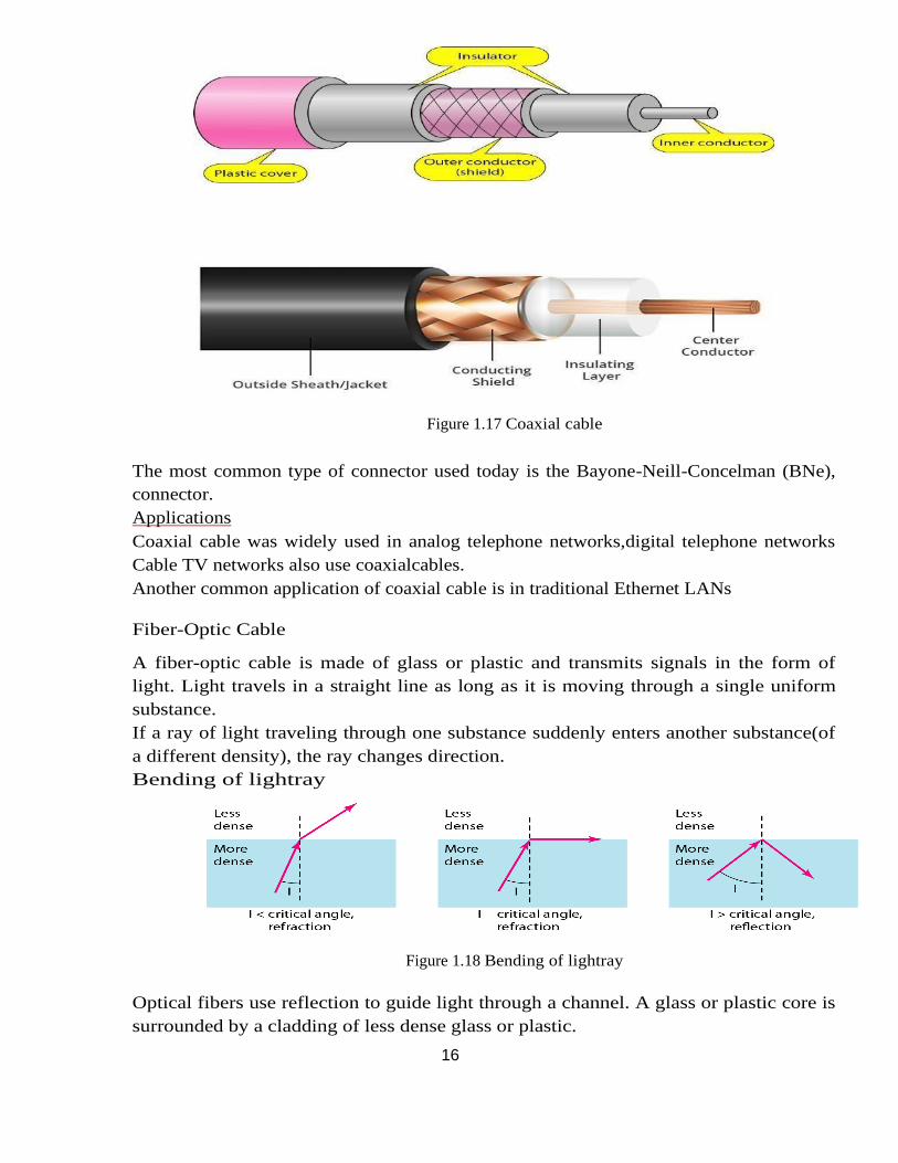
Coaxial Cable
Coaxial cable (or coax) carries signals of higher frequency ranges than those in twisted
pair cable. coax has a central core conductor of solid or stranded wire (usuallycopper)
enclosed in an insulating sheath, which is, in turn, encased in an outer conductor of metal
foil, braid, or a combination of the two. The outer metallic wrapping serves both as a
shield against noise and as the second conductor, which completes the circuit.This outer
conductor is also enclosed in an insulating sheath, and the whole cable is protected by a
plastic cover.
16
Figure 1.17 Coaxial cable
The most common type of connector used today is the Bayone-Neill-Concelman (BNe),
connector.
Applications
Coaxial cable was widely used in analog telephone networks,digital telephone networks
Cable TV networks also use coaxialcables.
Another common application of coaxial cable is in traditional Ethernet LANs
Fiber-Optic Cable
A fiber-optic cable is made of glass or plastic and transmits signals in the form of
light. Light travels in a straight line as long as it is moving through a single uniform
substance.
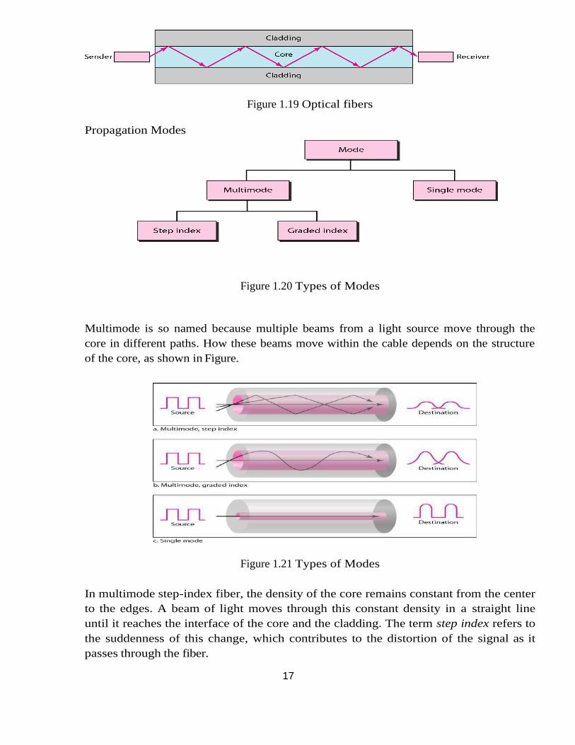
If a ray of light traveling through one substance suddenly enters another substance(of
a different density), the ray changes direction.
Bending of lightray
Figure 1.18 Bending of lightray
Optical fibers use reflection to guide light through a channel. A glass or plastic core is
surrounded by a cladding of less dense glass or plastic.
17
Figure 1.19 Optical fibers
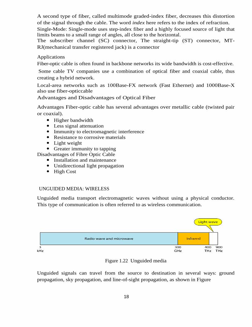
Propagation Modes
Figure 1.20 Types of Modes
Multimode is so named because multiple beams from a light source move through the
core in different paths. How these beams move within the cable depends on the structure
of the core, as shown in Figure.
Figure 1.21 Types of Modes
In multimode step-index fiber, the density of the core remains constant from the center
to the edges. A beam of light moves through this constant density in a straight line
until it reaches the interface of the core and the cladding. The term step index refers to
the suddenness of this change, which contributes to the distortion of the signal as it
passes through the fiber.
18
A second type of fiber, called multimode graded-index fiber, decreases this distortion
of the signal through the cable. The word index here refers to the index of refraction.
Single-Mode: Single-mode uses step-index fiber and a highly focused source of light that
limits beams to a small range of angles, all close to the horizontal.
The subscriber channel (SC) connector, The straight-tip (ST) connector, MT-
RJ(mechanical transfer registered jack) is a connector
Applications
Fiber-optic cable is often found in backbone networks its wide bandwidth is cost-effective.
Some cable TV companies use a combination of optical fiber and coaxial cable, thus
creating a hybrid network.
Local-area networks such as 100Base-FX network (Fast Ethernet) and 1000Base-X
also use fiber-opticcable
Advantages and Disadvantages of Optical Fiber
Advantages Fiber-optic cable has several advantages over metallic cable (twisted pair
or coaxial).
Higher bandwidth
Less signal attenuation
Immunity to electromagnetic interference
Resistance to corrosive materials
Light weight
Greater immunity to tapping
Disadvantages of Fibre Optic Cable
Installation and maintenance
Unidirectional light propagation
High Cost
UNGUIDED MEDIA: WIRELESS
Unguided media transport electromagnetic waves without using a physical conductor.
This type of communication is often referred to as wireless communication.
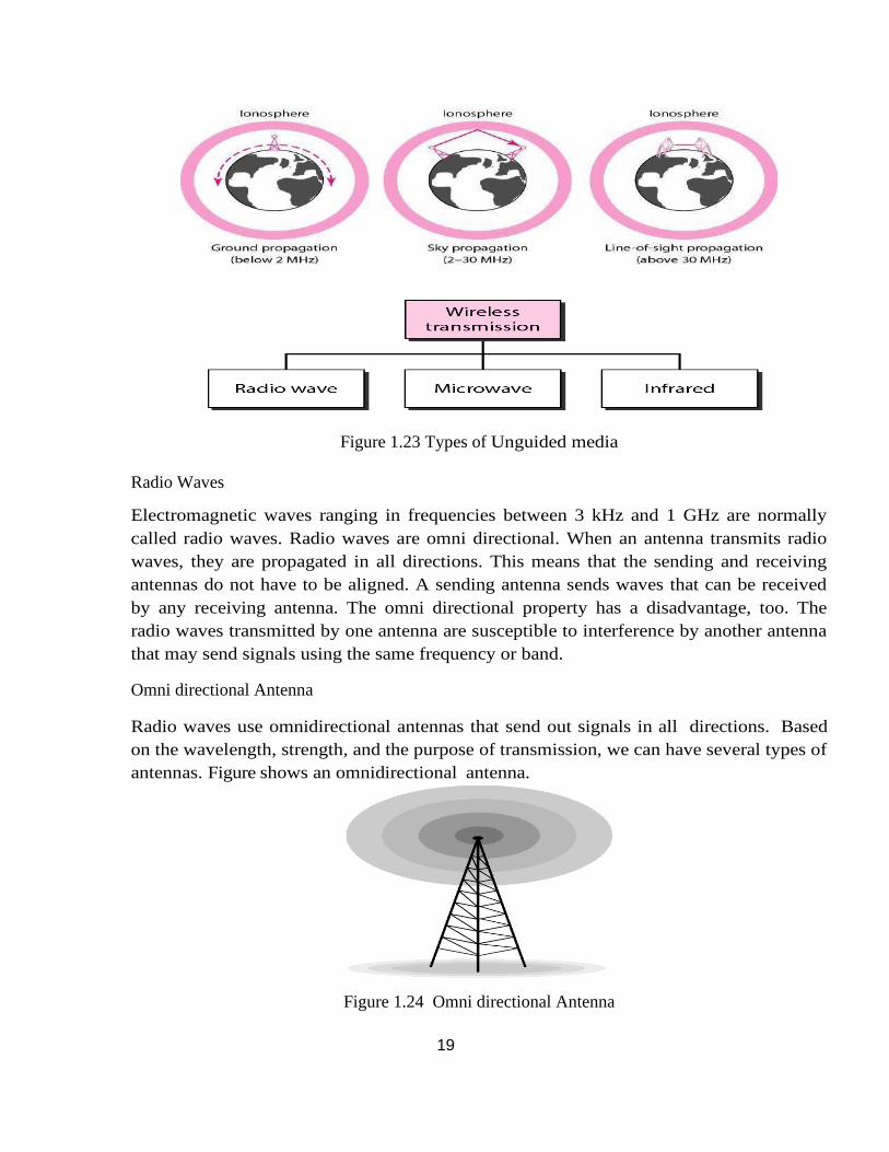
Figure 1.22 Unguided media
Unguided signals can travel from the source to destination in several ways: ground
propagation, sky propagation, and line-of-sight propagation, as shown in Figure
19
Figure 1.23 Types of Unguided media
Radio Waves
Electromagnetic waves ranging in frequencies between 3 kHz and 1 GHz are normally
called radio waves. Radio waves are omni directional. When an antenna transmits radio
waves, they are propagated in all directions. This means that the sending and receiving
antennas do not have to be aligned. A sending antenna sends waves that can be received
by any receiving antenna. The omni directional property has a disadvantage, too. The
radio waves transmitted by one antenna are susceptible to interference by another antenna
that may send signals using the same frequency or band.
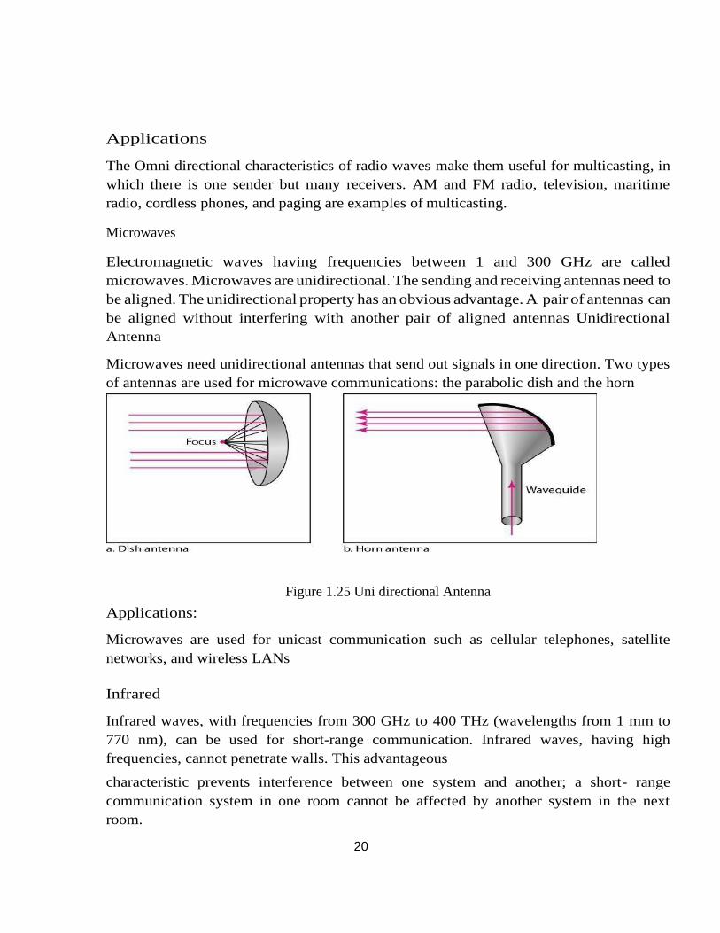
Omni directional Antenna
Radio waves use omnidirectional antennas that send out signals in all directions. Based
on the wavelength, strength, and the purpose of transmission, we can have several types of
antennas. Figure shows an omnidirectional antenna.
Figure 1.24 Omni directional Antenna
20
Applications
The Omni directional characteristics of radio waves make them useful for multicasting, in
which there is one sender but many receivers. AM and FM radio, television, maritime
radio, cordless phones, and paging are examples of multicasting.
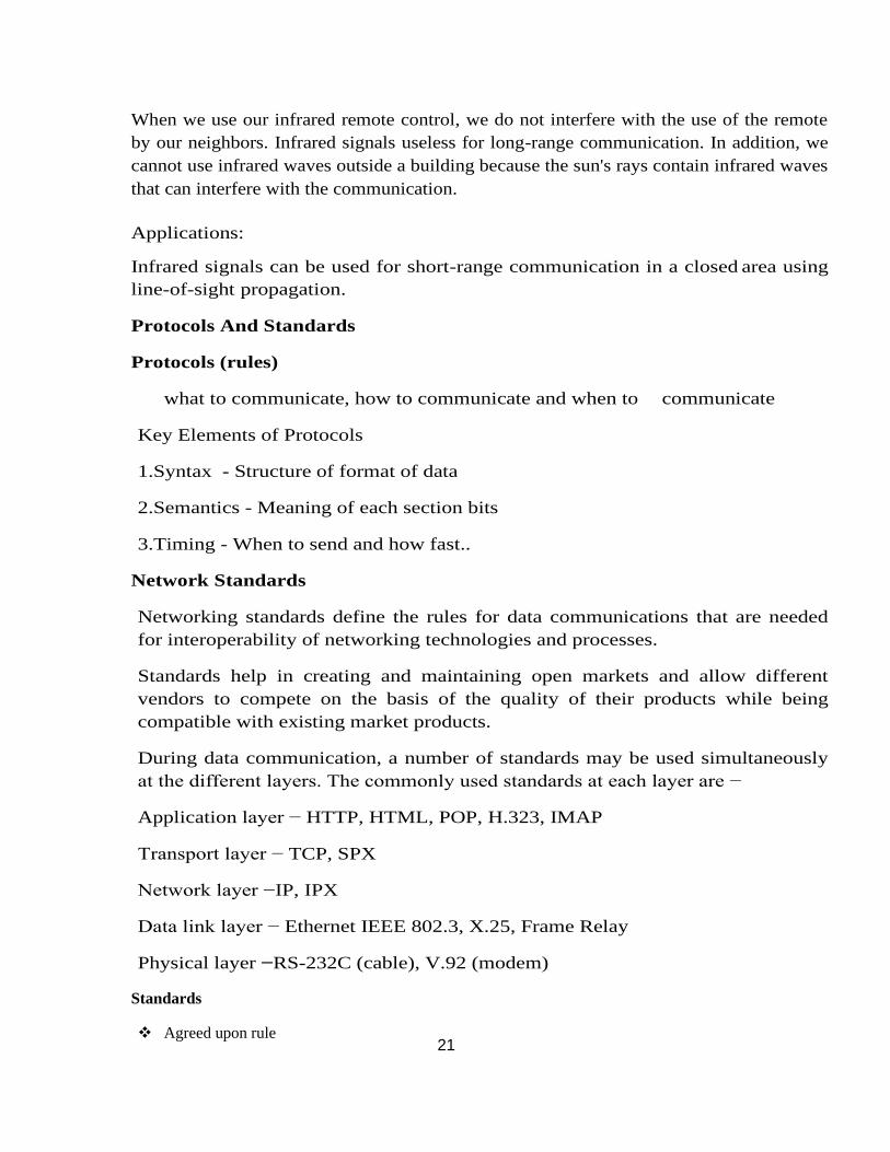
Microwaves
Electromagnetic waves having frequencies between 1 and 300 GHz are called
microwaves. Microwaves are unidirectional. The sending and receiving antennas need to
be aligned. The unidirectional property has an obvious advantage. A pair of antennas can
be aligned without interfering with another pair of aligned antennas Unidirectional
Antenna
Microwaves need unidirectional antennas that send out signals in one direction. Two types
of antennas are used for microwave communications: the parabolic dish and the horn
Figure 1.25 Uni directional Antenna
Applications:
Microwaves are used for unicast communication such as cellular telephones, satellite
networks, and wireless LANs
Infrared
Infrared waves, with frequencies from 300 GHz to 400 THz (wavelengths from 1 mm to
770 nm), can be used for short-range communication. Infrared waves, having high
frequencies, cannot penetrate walls. This advantageous
characteristic prevents interference between one system and another; a short- range
communication system in one room cannot be affected by another system in the next
room.
21
When we use our infrared remote control, we do not interfere with the use of the remote
by our neighbors. Infrared signals useless for long-range communication. In addition, we
cannot use infrared waves outside a building because the sun's rays contain infrared waves
that can interfere with the communication.
Applications:
Infrared signals can be used for short-range communication in a closed area using
line-of-sight propagation.
Protocols And Standards
Protocols (rules)
what to communicate, how to communicate and when to communicate
Key Elements of Protocols
1.Syntax - Structure of format of data
2.Semantics - Meaning of each section bits
3.Timing - When to send and how fast..
Network Standards
Networking standards define the rules for data communications that are needed
for interoperability of networking technologies and processes.
Standards help in creating and maintaining open markets and allow different
vendors to compete on the basis of the quality of their products while being
compatible with existing market products.
During data communication, a number of standards may be used simultaneously
at the different layers. The commonly used standards at each layer are −
Application layer − HTTP, HTML, POP, H.323, IMAP
Transport layer − TCP, SPX
Network layer −IP, IPX
Data link layer − Ethernet IEEE 802.3, X.25, Frame Relay
Physical layer −RS-232C (cable), V.92 (modem)
Standards
❖ Agreed upon rule
22
❖ A common set of rules
Categories of Standards
1.De facto - By convention or by fact
❖ These are the standards that are followed without any formal plan or approval by any
organization.
❖ They have come into existence due to traditions or facts.
❖ For example, the HTTP had started as a de facto standard.
2.De jure - By Law or by Government
❖ These standards are the ones which have been adopted through legislation by any officially
recognized standards organization.
❖ Most of the communication standards that are used today are de jure standards.
Some of the noted standards organizations are
❖ International Standards Organization (ISO)
❖ International Telecommunication Union (ITU)
❖ Institute of Electronics and Electrical Engineers (IEEE)
❖ American National Standards Institute (ANSI)
❖ Internet Research Task Force (IETF)
❖ Electronic Industries Association (EIA)
Switching
A network is a set of connected devices. Whenever we have multiple devices, we have the
problem of how to connect them to make one-to-one communication possible. One
solution is to make a point-to-point connection between each pair of devices (a mesh
topology) or between a central device and every other device (a star topology). These
methods, however, are impractical and wasteful when applied to very large networks.
The number and length of the links require too much infrastructure to be cost-
efficient, and the majority of those links would be idle most of the time.
A better solution is switching. A switched network consists of a series of
interlinked nodes, called switches. Switches are devices capable of creating temporary
connections between two or more devices linked to the switch. In a switched network,
some of these nodes are connected to the end systems (computers or telephones, for
example). Others are used only for routing. Figure shows a switched network.
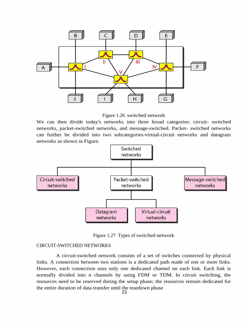
23
Figure 1.26 switched network
We can then divide today's networks into three broad categories: circuit- switched
networks, packet-switched networks, and message-switched. Packet- switched networks
can further be divided into two subcategories-virtual-circuit networks and datagram
networks as shown in Figure.
Figure 1.27 Types of switched network
CIRCUIT-SWITCHED NETWORKS
A circuit-switched network consists of a set of switches connected by physical
links. A connection between two stations is a dedicated path made of one or more links.
However, each connection uses only one dedicated channel on each link. Each link is
normally divided into n channels by using FDM or TDM. In circuit switching, the
resources need to be reserved during the setup phase; the resources remain dedicated for
the entire duration of data transfer until the teardown phase
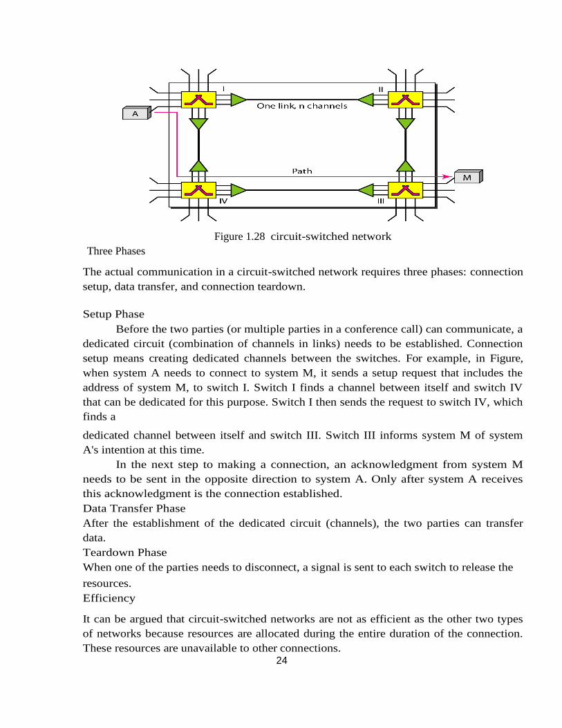
24
Figure 1.28 circuit-switched network
Three Phases
The actual communication in a circuit-switched network requires three phases: connection
setup, data transfer, and connection teardown.
Setup Phase
Before the two parties (or multiple parties in a conference call) can communicate, a
dedicated circuit (combination of channels in links) needs to be established. Connection
setup means creating dedicated channels between the switches. For example, in Figure,
when system A needs to connect to system M, it sends a setup request that includes the
address of system M, to switch I. Switch I finds a channel between itself and switch IV
that can be dedicated for this purpose. Switch I then sends the request to switch IV, which
finds a
dedicated channel between itself and switch III. Switch III informs system M of system
A's intention at this time.
In the next step to making a connection, an acknowledgment from system M
needs to be sent in the opposite direction to system A. Only after system A receives
this acknowledgment is the connection established.
Data Transfer Phase
After the establishment of the dedicated circuit (channels), the two parties can transfer
data.
Teardown Phase
When one of the parties needs to disconnect, a signal is sent to each switch to release the
resources.
Efficiency
It can be argued that circuit-switched networks are not as efficient as the other two types
of networks because resources are allocated during the entire duration of the connection.
These resources are unavailable to other connections.
25
Delay
Although a circuit-switched network normally has low efficiency, the delay in this type of
network is minimal. During data transfer the data are not delayed at each switch; the
resources are allocated for the duration of the connection.
The total delay is due to the time needed to create the connection, transfer data, and
disconnect the circuit.
Switching at the physical layer in the traditional telephone network uses the circuit-
switching
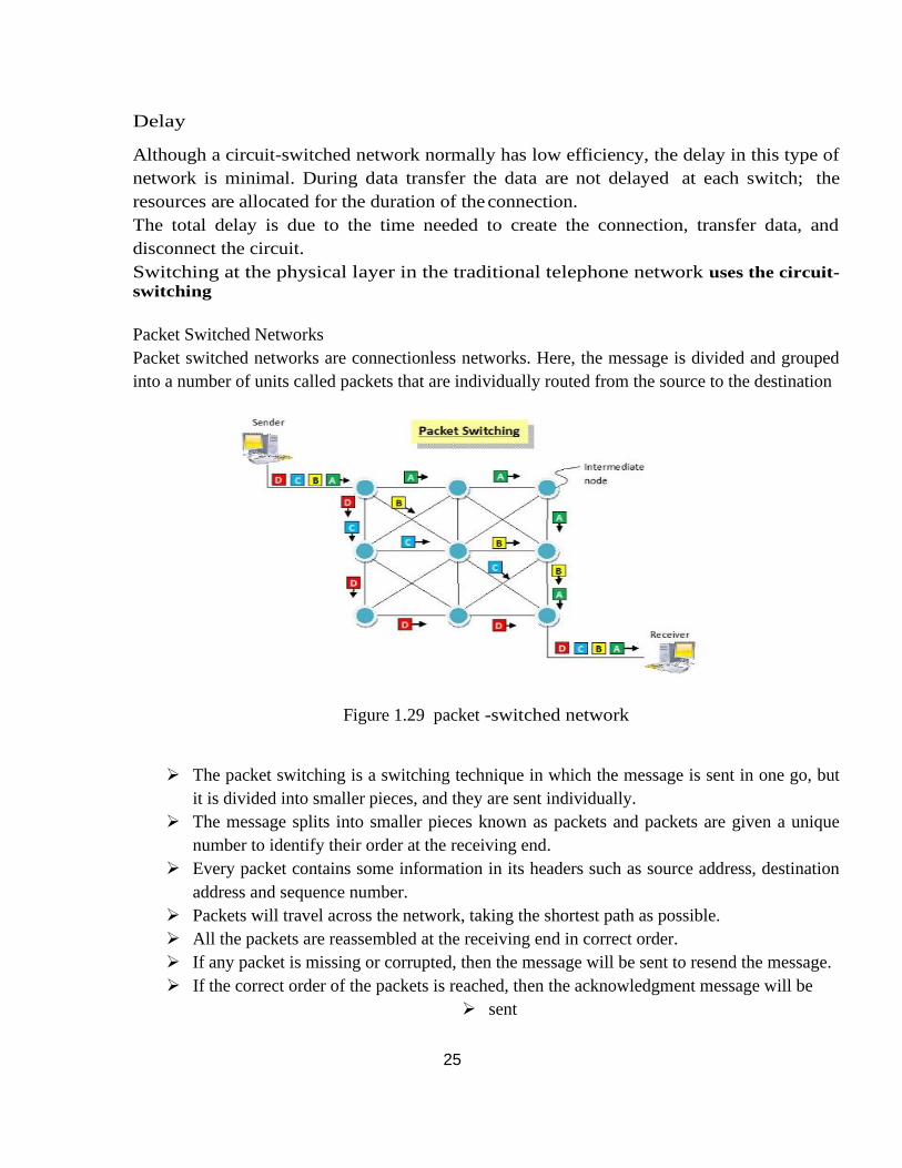
Packet Switched Networks
Packet switched networks are connectionless networks. Here, the message is divided and grouped
into a number of units called packets that are individually routed from the source to the destination
Figure 1.29 packet -switched network
➢ The packet switching is a switching technique in which the message is sent in one go, but
it is divided into smaller pieces, and they are sent individually.
➢ The message splits into smaller pieces known as packets and packets are given a unique
number to identify their order at the receiving end.
➢ Every packet contains some information in its headers such as source address, destination
address and sequence number.
➢ Packets will travel across the network, taking the shortest path as possible.
➢ All the packets are reassembled at the receiving end in correct order.
➢ If any packet is missing or corrupted, then the message will be sent to resend the message.
➢ If the correct order of the packets is reached, then the acknowledgment message will be
➢ sent
26
Approaches Of Packet Switching
➢ There are two approaches to Packet Switching:
➢ Datagram Packet switching:
➢ It is a packet switching technology in which packet is known as a datagram, is considered
as an independent entity. Each packet contains the information about the destination and
switch uses this information to forward the packet to the correct destination.
➢ The packets are reassembled at the receiving end in correct order.
➢ In Datagram Packet Switching technique, the path is not fixed.
➢ Intermediate nodes take the routing decisions to forward the packets.
➢ Datagram Packet Switching is also known as connectionless switching.
DATAGRAM NETWORKS
In a packet-switched network, there is no resource reservation; resources are allocated on
demand. The allocation is done on a first come, first-served basis. When a switch receives
a packet, no matter what is the source or destination, the packet must wait if there are
other packets being processed. This lack of reservation may create delay. For example, if
we do not have a reservation at a restaurant, we might have to wait.
In a datagram network, each packet is treated independently of all others. Packets
in this approach are referred to as datagrams. Datagram switching is normally done at the
network layer.
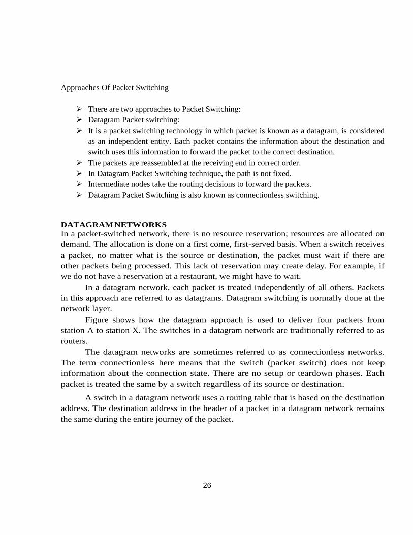
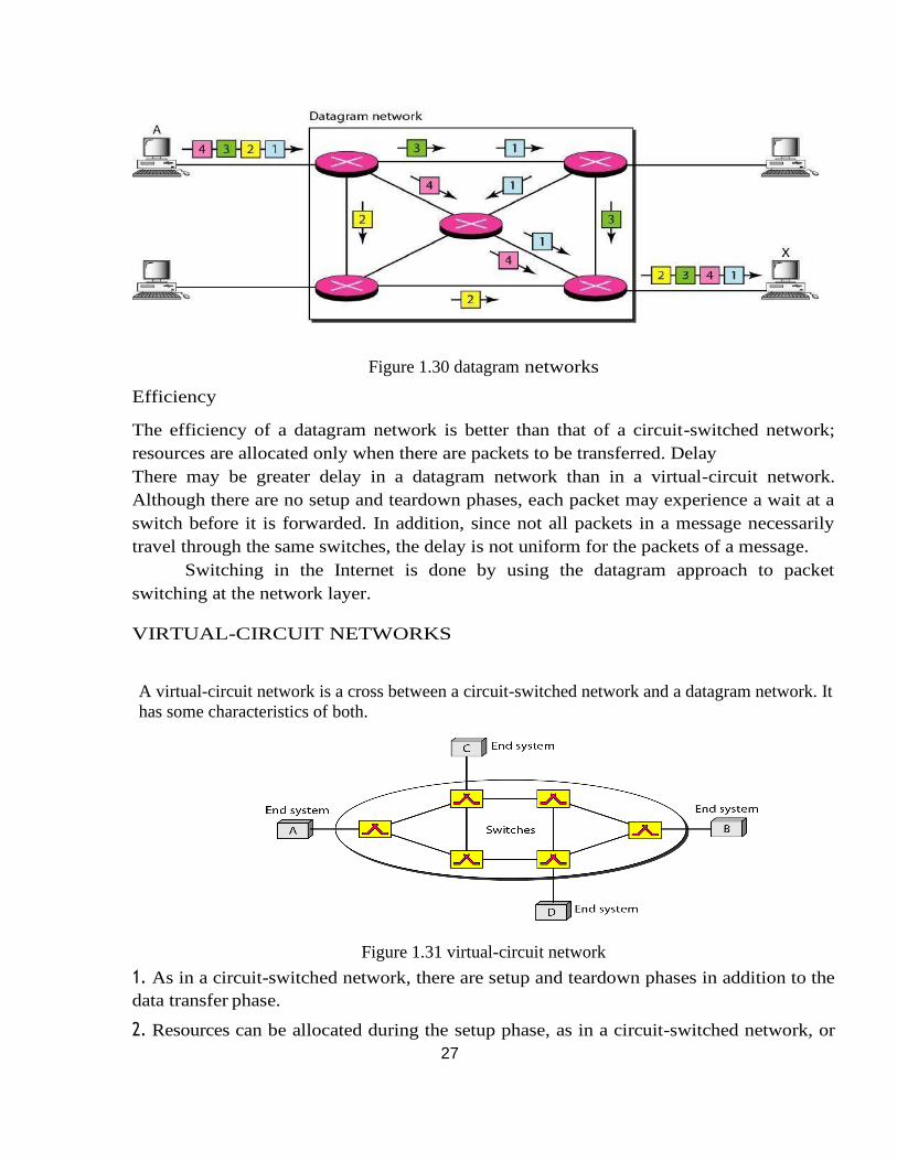
Figure shows how the datagram approach is used to deliver four packets from
station A to station X. The switches in a datagram network are traditionally referred to as
routers.
The datagram networks are sometimes referred to as connectionless networks.
The term connectionless here means that the switch (packet switch) does not keep
information about the connection state. There are no setup or teardown phases. Each
packet is treated the same by a switch regardless of its source or destination.
A switch in a datagram network uses a routing table that is based on the destination
address. The destination address in the header of a packet in a datagram network remains
the same during the entire journey of the packet.
27
Figure 1.30 datagram networks
Efficiency
The efficiency of a datagram network is better than that of a circuit-switched network;
resources are allocated only when there are packets to be transferred. Delay
There may be greater delay in a datagram network than in a virtual-circuit network.
Although there are no setup and teardown phases, each packet may experience a wait at a
switch before it is forwarded. In addition, since not all packets in a message necessarily
travel through the same switches, the delay is not uniform for the packets of a message.
Switching in the Internet is done by using the datagram approach to packet
switching at the network layer.
VIRTUAL-CIRCUIT NETWORKS
A virtual-circuit network is a cross between a circuit-switched network and a datagram network. It
has some characteristics of both.
Figure 1.31 virtual-circuit network
1. As in a circuit-switched network, there are setup and teardown phases in addition to the
data transfer phase.
2. Resources can be allocated during the setup phase, as in a circuit-switched network, or
28
on demand, as in a datagram network.
3. As in a datagram network, data are packetized and each packet carries an address in the
header. However, the address in the header has local jurisdiction (it defines what should be
the next switch and the channel on which the packet is being carried), not end-to-end
jurisdiction.
4. As in a circuit-switched network, all packets follow the same path established during
the connection.
5. A virtual-circuit network is normally implemented in the data link layer, while a circuit-
switched network is implemented in the physical layer and a datagram network in the
network layer.
Addressing
In a virtual-circuit network, two types of addressing are involved: global and local
(virtual-circuit identifier).
Global Addressing
A source or a destination needs to have a global address-an address that can be unique in
the scope of the network.
Virtual-Circuit Identifier
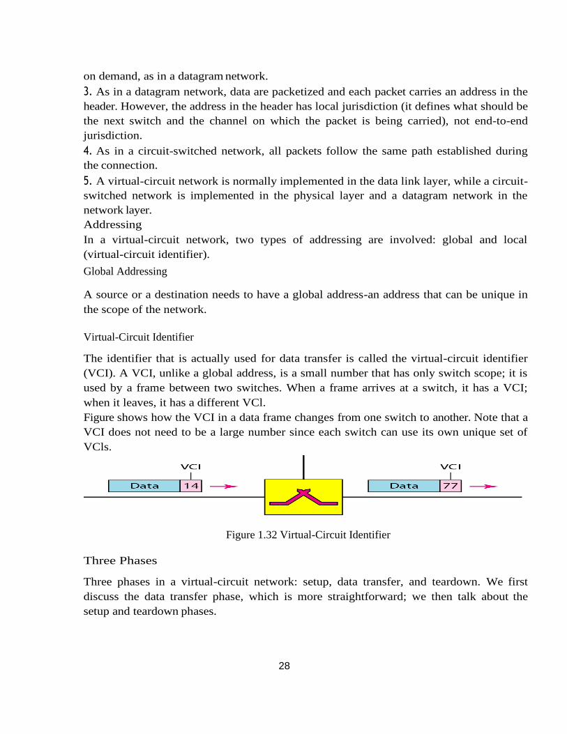
The identifier that is actually used for data transfer is called the virtual-circuit identifier
(VCI). A VCI, unlike a global address, is a small number that has only switch scope; it is
used by a frame between two switches. When a frame arrives at a switch, it has a VCI;
when it leaves, it has a different VCl.
Figure shows how the VCI in a data frame changes from one switch to another. Note that a
VCI does not need to be a large number since each switch can use its own unique set of
VCls.
Figure 1.32 Virtual-Circuit Identifier
Three Phases
Three phases in a virtual-circuit network: setup, data transfer, and teardown. We first
discuss the data transfer phase, which is more straightforward; we then talk about the
setup and teardown phases.
29
Data Transfer Phase
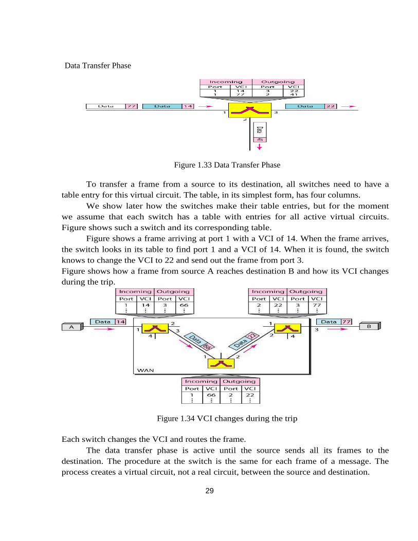
Figure 1.33 Data Transfer Phase
To transfer a frame from a source to its destination, all switches need to have a
table entry for this virtual circuit. The table, in its simplest form, has four columns.
We show later how the switches make their table entries, but for the moment
we assume that each switch has a table with entries for all active virtual circuits.
Figure shows such a switch and its corresponding table.
Figure shows a frame arriving at port 1 with a VCI of 14. When the frame arrives,
the switch looks in its table to find port 1 and a VCI of 14. When it is found, the switch
knows to change the VCI to 22 and send out the frame from port 3.
Figure shows how a frame from source A reaches destination B and how its VCI changes
during the trip.
Figure 1.34 VCI changes during the trip
Each switch changes the VCI and routes the frame.
The data transfer phase is active until the source sends all its frames to the
destination. The procedure at the switch is the same for each frame of a message. The
process creates a virtual circuit, not a real circuit, between the source and destination.
30
Setup Phase
In the setup phase, a switch creates an entry for a virtual circuit. For example, suppose
source A needs to create a virtual circuit to B. Two steps are required: the setup request
and the acknowledgment.
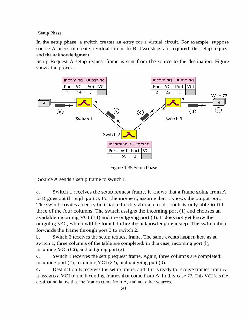
Setup Request A setup request frame is sent from the source to the destination. Figure
shows the process.
Figure 1.35 Setup Phase
Source A sends a setup frame to switch 1.
a. Switch 1 receives the setup request frame. It knows that a frame going from A
to B goes out through port 3. For the moment, assume that it knows the output port.
The switch creates an entry in its table for this virtual circuit, but it is only able to fill
three of the four columns. The switch assigns the incoming port (1) and chooses an
available incoming VCI (14) and the outgoing port (3). It does not yet know the
outgoing VCI, which will be found during the acknowledgment step. The switch then
forwards the frame through port 3 to switch 2.
b. Switch 2 receives the setup request frame. The same events happen here as at
switch 1; three columns of the table are completed: in this case, incoming port (l),
incoming VCI (66), and outgoing port (2).
c. Switch 3 receives the setup request frame. Again, three columns are completed:
incoming port (2), incoming VCI (22), and outgoing port (3).
d. Destination B receives the setup frame, and if it is ready to receive frames from A,
it assigns a VCI to the incoming frames that come from A, in this case 77. This VCI lets the
destination know that the frames come from A, and not other sources.
31
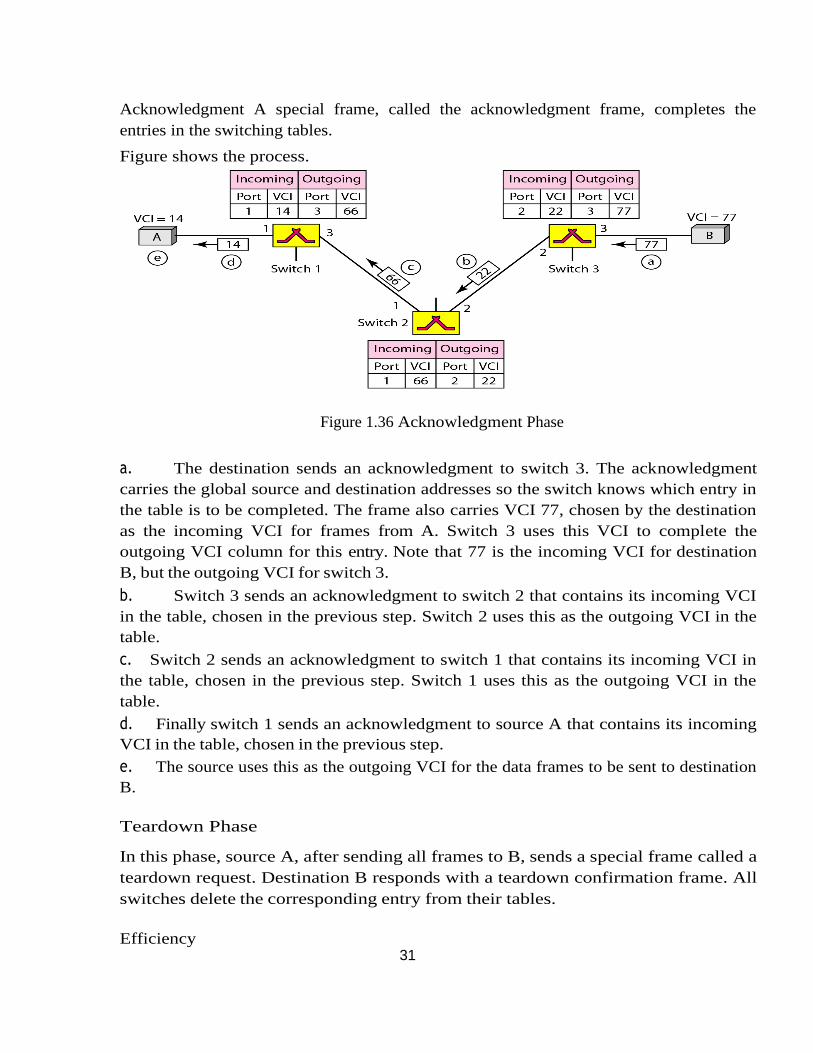
Acknowledgment A special frame, called the acknowledgment frame, completes the
entries in the switching tables.
Figure shows the process.
Figure 1.36 Acknowledgment Phase
a. The destination sends an acknowledgment to switch 3. The acknowledgment
carries the global source and destination addresses so the switch knows which entry in
the table is to be completed. The frame also carries VCI 77, chosen by the destination
as the incoming VCI for frames from A. Switch 3 uses this VCI to complete the
outgoing VCI column for this entry. Note that 77 is the incoming VCI for destination
B, but the outgoing VCI for switch 3.
b. Switch 3 sends an acknowledgment to switch 2 that contains its incoming VCI
in the table, chosen in the previous step. Switch 2 uses this as the outgoing VCI in the
table.
c. Switch 2 sends an acknowledgment to switch 1 that contains its incoming VCI in
the table, chosen in the previous step. Switch 1 uses this as the outgoing VCI in the
table.
d. Finally switch 1 sends an acknowledgment to source A that contains its incoming
VCI in the table, chosen in the previous step.
e. The source uses this as the outgoing VCI for the data frames to be sent to destination
B.
Teardown Phase
In this phase, source A, after sending all frames to B, sends a special frame called a
teardown request. Destination B responds with a teardown confirmation frame. All
switches delete the corresponding entry from their tables.
Efficiency
32
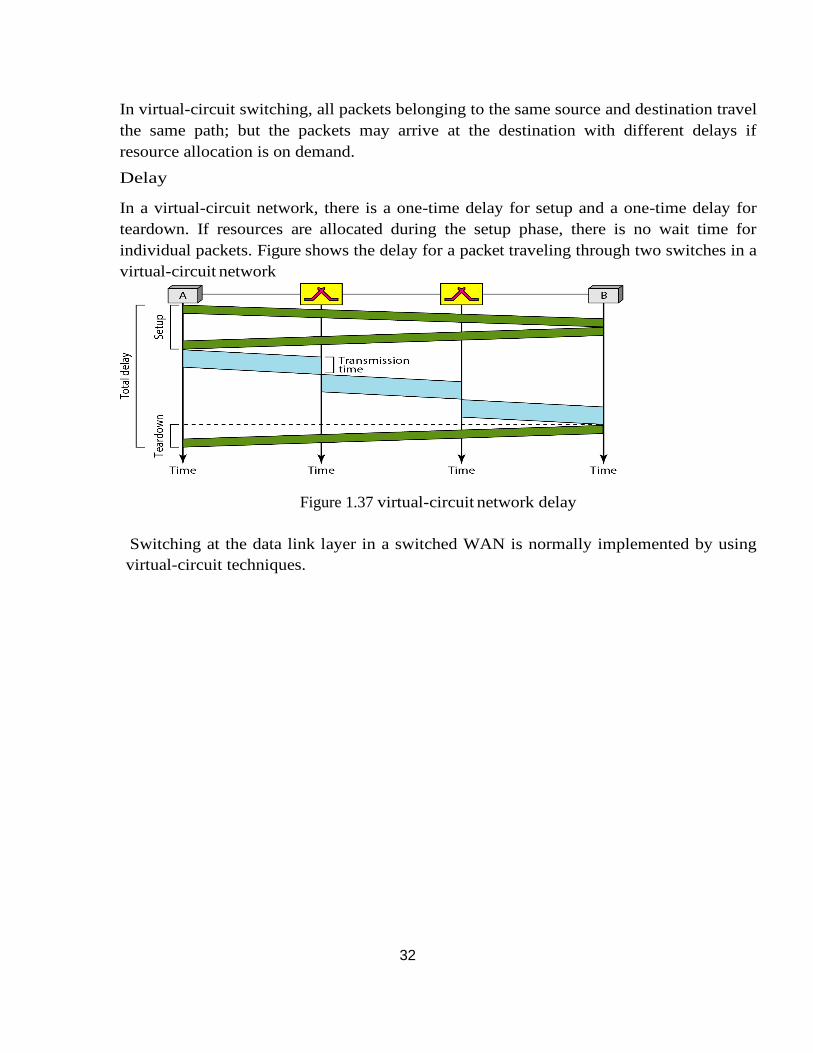
In virtual-circuit switching, all packets belonging to the same source and destination travel
the same path; but the packets may arrive at the destination with different delays if
resource allocation is on demand.
Delay
In a virtual-circuit network, there is a one-time delay for setup and a one-time delay for
teardown. If resources are allocated during the setup phase, there is no wait time for
individual packets. Figure shows the delay for a packet traveling through two switches in a
virtual-circuit network
Figure 1.37 virtual-circuit network delay
Switching at the data link layer in a switched WAN is normally implemented by using
virtual-circuit techniques.
33
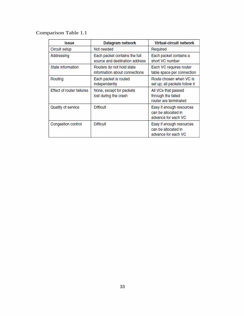
Comparison Table 1.1
34
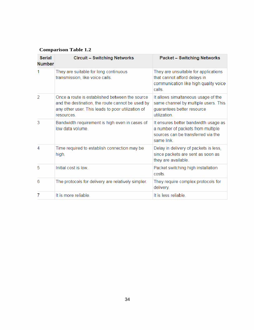
Comparison Table 1.2
35
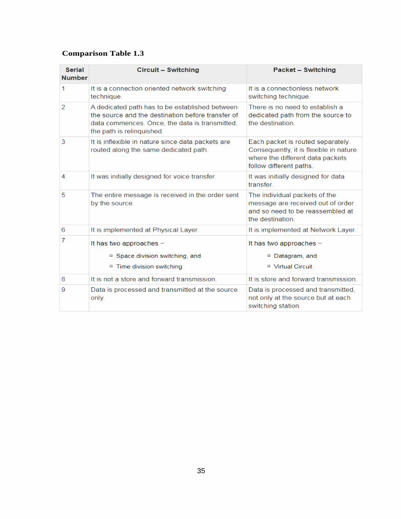
Comparison Table 1.3
36
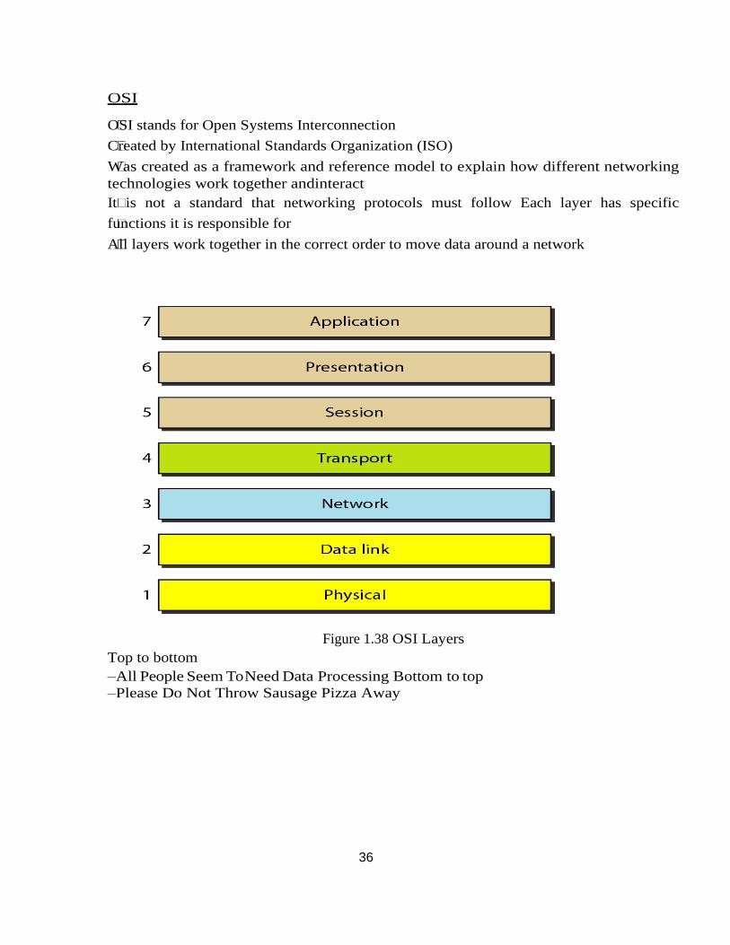
OSI
OSI stands for Open Systems Interconnection
Created by International Standards Organization (ISO)
Was created as a framework and reference model to explain how different networking
technologies work together andinteract
It is not a standard that networking protocols must follow Each layer has specific
functions it is responsible for
All layers work together in the correct order to move data around a network
Figure 1.38 OSI Layers
Top to bottom
–All People Seem To Need Data Processing Bottom to top
–Please Do Not Throw Sausage Pizza Away
37
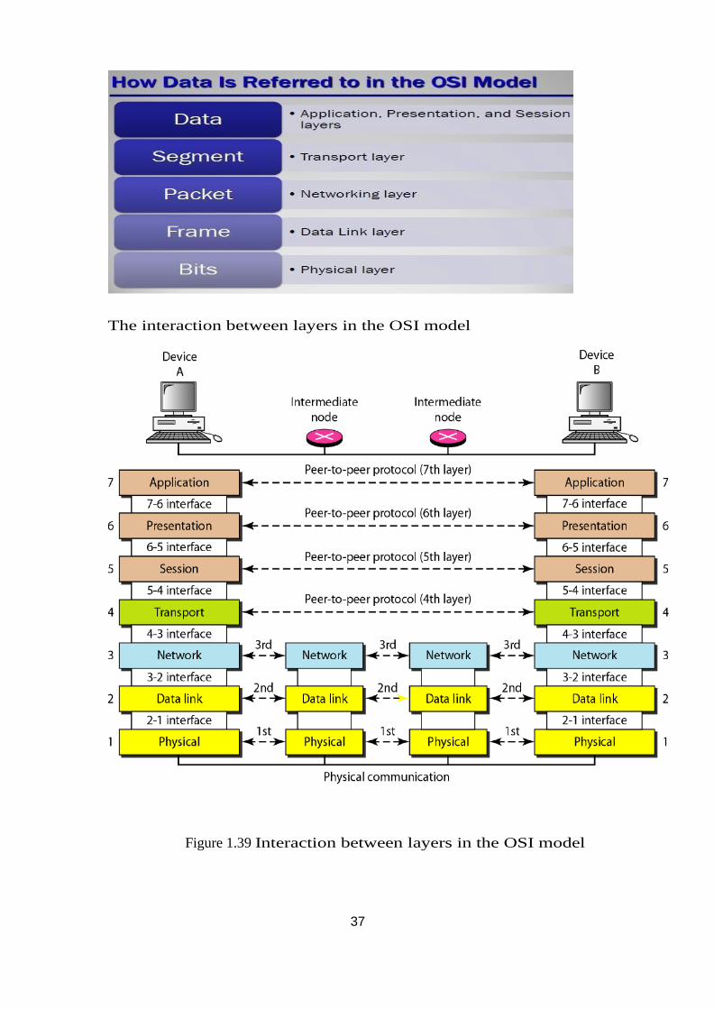
The interaction between layers in the OSI model
Figure 1.39 Interaction between layers in the OSI model
38
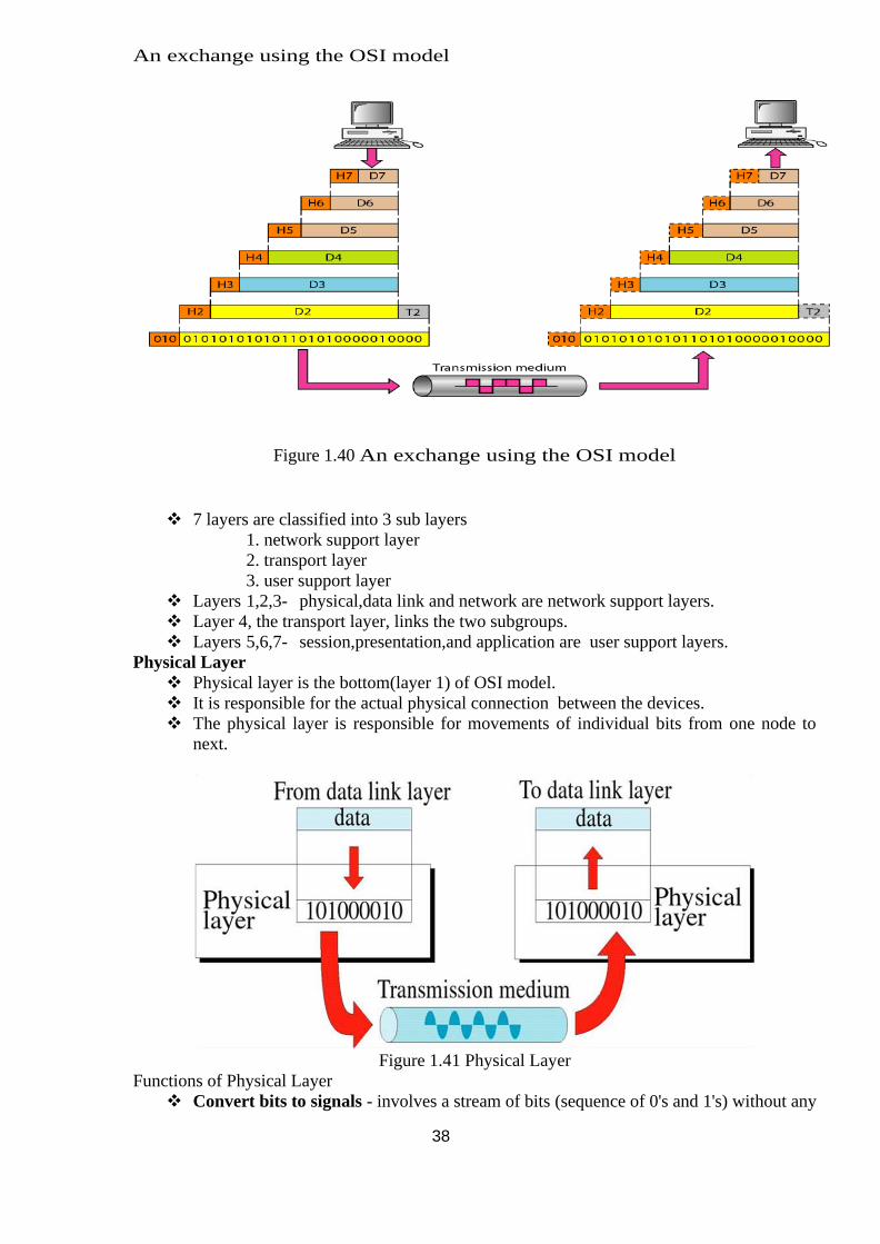
An exchange using the OSI model
Figure 1.40 An exchange using the OSI model
❖ 7 layers are classified into 3 sub layers
1. network support layer
2. transport layer
3. user support layer
❖ Layers 1,2,3- physical,data link and network are network support layers.
❖ Layer 4, the transport layer, links the two subgroups.
❖ Layers 5,6,7- session,presentation,and application are user support layers.
Physical Layer
❖ Physical layer is the bottom(layer 1) of OSI model.
❖ It is responsible for the actual physical connection between the devices.
❖ The physical layer is responsible for movements of individual bits from one node to
next.
Figure 1.41 Physical Layer
Functions of Physical Layer
❖ Convert bits to signals - involves a stream of bits (sequence of 0's and 1's) without any
39
interpretation. To be transmitted bits must be encoded into the signals - electrical or
optical.
❖ Bit synchronization - It is necessary to have synchronization between sender and
receiver at the bit level that is the clocks of the sender and the receiver must be
synchronized.
❖ Physical characteristics of interfaces and media - It defines the characteristics of the
interface between the devices and the transmission medium. It also defines the type of
transmission medium.
❖ Bit rate control- also defines the transmission rate(Data Rate) i.e. the number
of bits sent per second
❖ Line configuration - 1. Point-to-point 2. Multipoint
❖ Physical topology – Mesh,star,bus,ring
❖ Transmission mode - simplex, half-duplex, or full-duplex
Multiplexing - Code-division multiplexing (CDM) is a technique in which each channel
transmits its bits as a coded channel-specific sequence of pulses
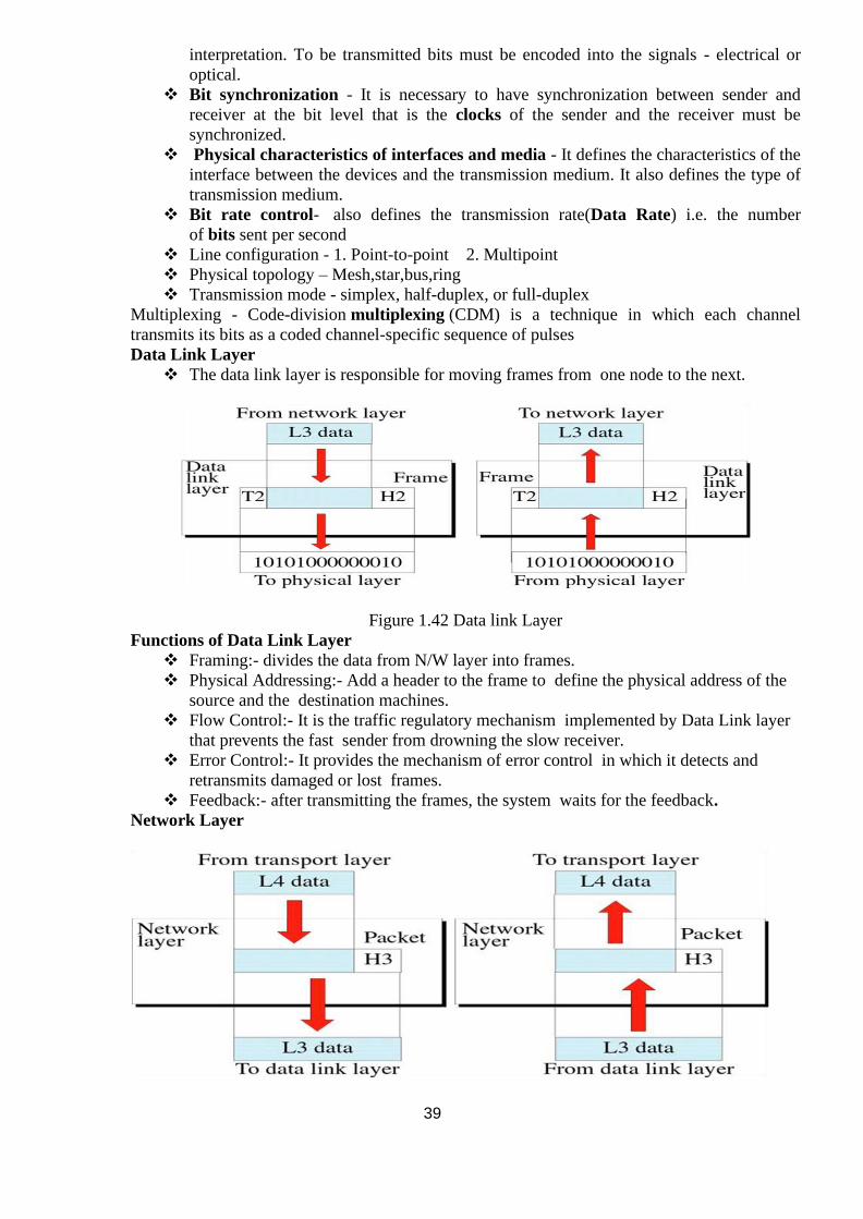
Data Link Layer
❖ The data link layer is responsible for moving frames from one node to the next.
Figure 1.42 Data link Layer
Functions of Data Link Layer
❖ Framing:- divides the data from N/W layer into frames.
❖ Physical Addressing:- Add a header to the frame to define the physical address of the
source and the destination machines.
❖ Flow Control:- It is the traffic regulatory mechanism implemented by Data Link layer
that prevents the fast sender from drowning the slow receiver.
❖ Error Control:- It provides the mechanism of error control in which it detects and
retransmits damaged or lost frames.
❖ Feedback:- after transmitting the frames, the system waits for the feedback.
Network Layer
40
Figure 1.43 Network Layer
Functions of Network layer
❖ It is responsible for the source to destination delivery of a packets across multiple
networks.
❖ Routing:-Provide mechanism to transmit data over independent networks that are
linked together.
❖ Logical addressing:- Adds Logical addresses of sender and Receiver.
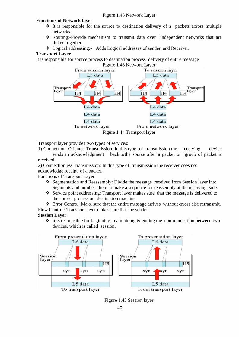
Transport Layer
It is responsible for source process to destination process delivery of entire message
Figure 1.43 Network Layer
Figure 1.44 Transport layer
Transport layer provides two types of services:
1) Connection Oriented Transmission: In this type of transmission the receiving device
sends an acknowledgment back to the source after a packet or group of packet is
received.
2) Connectionless Transmission: In this type of transmission the receiver does not
acknowledge receipt of a packet.
Functions of Transport Layer
❖ Segmentation and Reassembly: Divide the message received from Session layer into
Segments and number them to make a sequence for reassembly at the receiving side.
❖ Service point addressing: Transport layer makes sure that the message is delivered to
the correct process on destination machine.
❖ Error Control: Make sure that the entire message arrives without errors else retransmit.
Flow Control: Transport layer makes sure that the sender
Session Layer
❖ It is responsible for beginning, maintaining & ending the communication between two
devices, which is called session.
Figure 1.45 Session layer
41
Functions of Session Layer
❖ Establishment, maintaining and ending a session:
❖ Sends SYN packet – establish request
❖ Receives ACK & SYN- established
❖ To end – Sender sends ACK
❖ Dialog Control: The session layer allows two systems to enter into a dialog.
❖ Synchronization: Allows a process to add checkpoints to a stream of data.
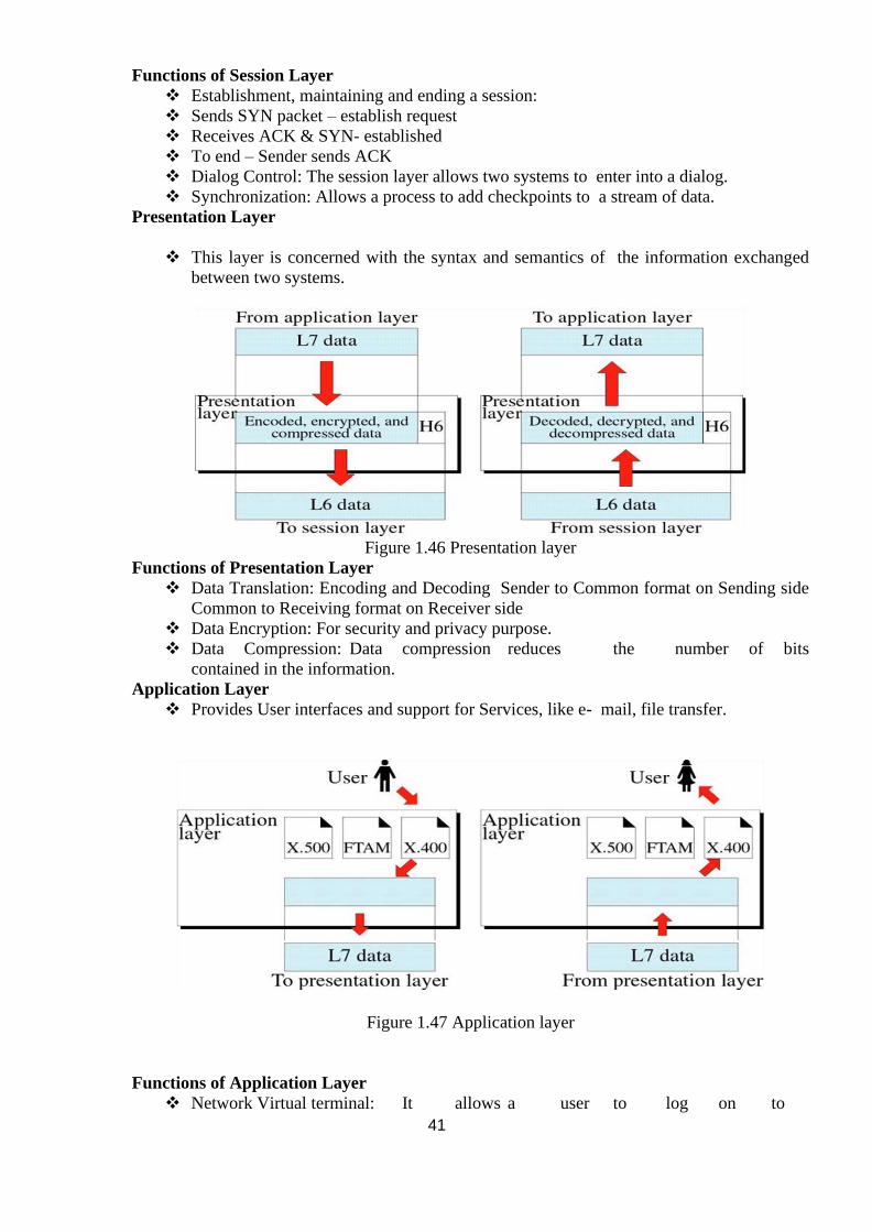
Presentation Layer
❖ This layer is concerned with the syntax and semantics of the information exchanged
between two systems.
Figure 1.46 Presentation layer
Functions of Presentation Layer
❖ Data Translation: Encoding and Decoding Sender to Common format on Sending side
Common to Receiving format on Receiver side
❖ Data Encryption: For security and privacy purpose.
❖ Data Compression: Data compression reduces the number of bits
contained in the information.
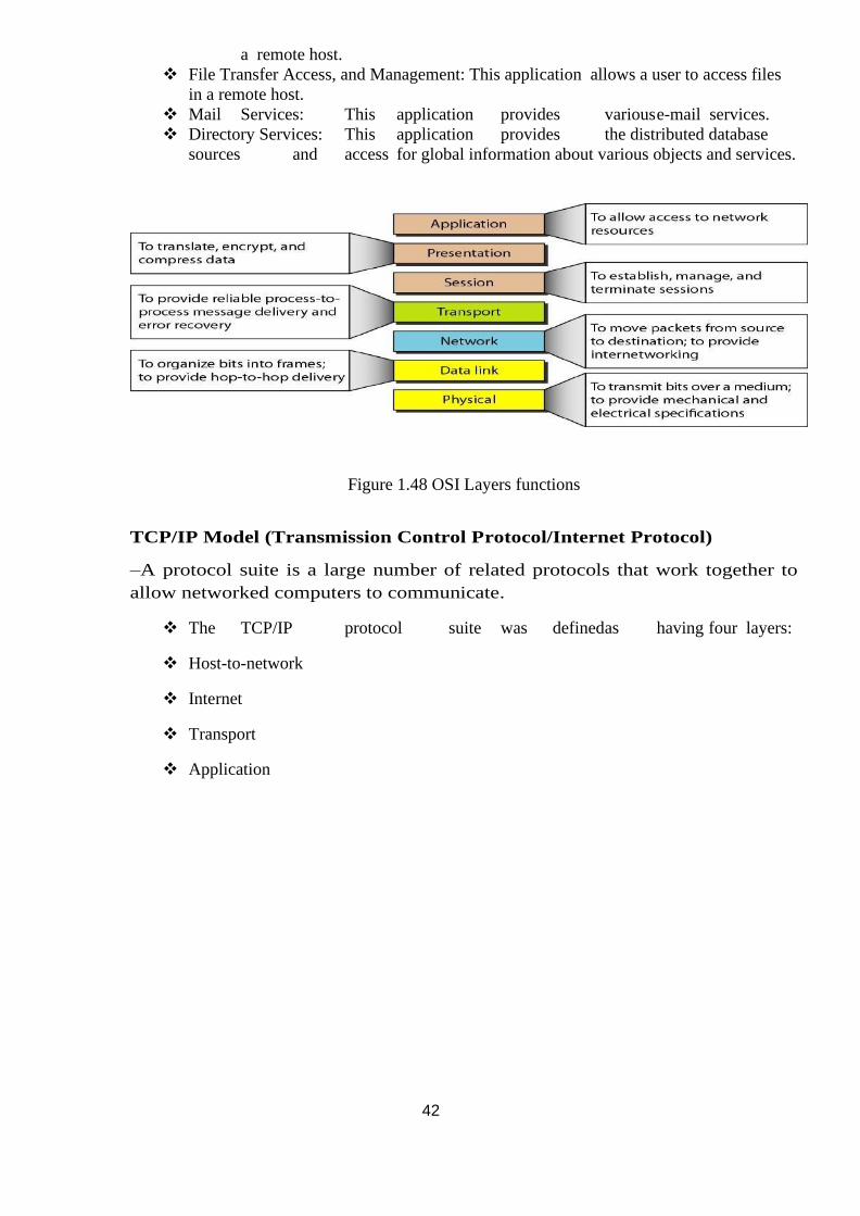
Application Layer
❖ Provides User interfaces and support for Services, like e- mail, file transfer.
Figure 1.47 Application layer
Functions of Application Layer
❖ Network Virtual terminal: It allows a user to log on to
42
a remote host.
❖ File Transfer Access, and Management: This application allows a user to access files
in a remote host.
❖ Mail Services: This application provides various e-mail services.
❖ Directory Services: This application provides the distributed database
sources and access for global information about various objects and services.
Figure 1.48 OSI Layers functions
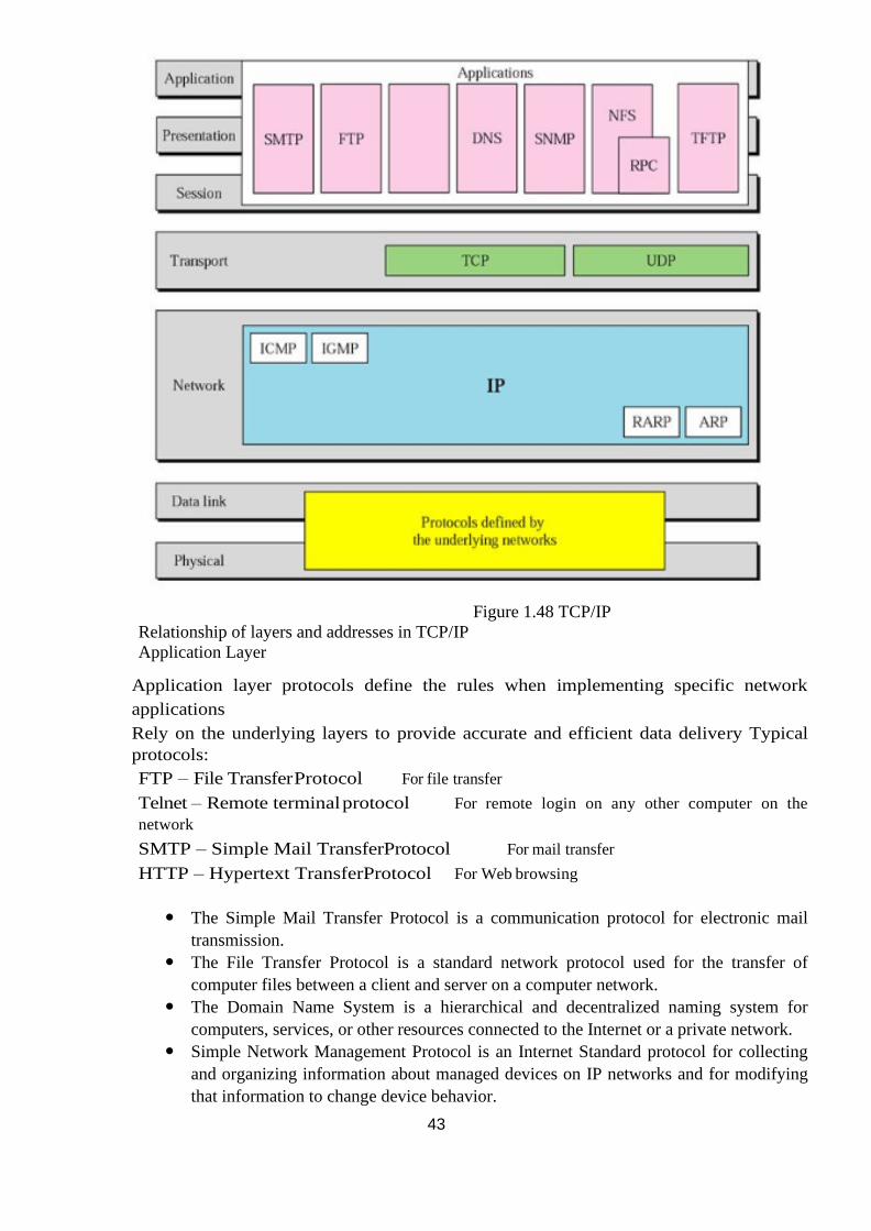
TCP/IP Model (Transmission Control Protocol/Internet Protocol)
–A protocol suite is a large number of related protocols that work together to
allow networked computers to communicate.
❖ The TCP/IP protocol suite was definedas having four layers:
❖ Host-to-network
❖ Internet
❖ Transport
❖ Application
43
Figure 1.48 TCP/IP
Relationship of layers and addresses in TCP/IP
Application Layer
Application layer protocols define the rules when implementing specific network
applications
Rely on the underlying layers to provide accurate and efficient data delivery Typical
protocols:
FTP – File Transfer Protocol For file transfer
Telnet – Remote terminal protocol For remote login on any other computer on the
network
SMTP – Simple Mail TransferProtocol For mail transfer
HTTP – Hypertext TransferProtocol For Web browsing
The Simple Mail Transfer Protocol is a communication protocol for electronic mail
transmission.
The File Transfer Protocol is a standard network protocol used for the transfer of
computer files between a client and server on a computer network.
The Domain Name System is a hierarchical and decentralized naming system for
computers, services, or other resources connected to the Internet or a private network.
Simple Network Management Protocol is an Internet Standard protocol for collecting
and organizing information about managed devices on IP networks and for modifying
that information to change device behavior.
44
Network File System is a distributed file system protocol allowing a user on a client
computer to access files over a computer network much like local storage is accessed.
Trivial File Transfer Protocol is a simple lockstep File Transfer Protocol which allows a
client to get a file from or put a file onto a remote host.
Encompasses same functions as these OSI Model layers Application Presentation Session
Transport Layer
TCP is a connection-oriented protocol
Does not mean it has a physical connection between sender and receiver
TCP provides the function to allow a connection virtually exists – also called virtual
circuit
UDP provides the functions:
Dividing a chunk of data intosegments
Reassembly segments into the originalchunk
Provide further the functions such as reordering and data resend Offering a reliable byte-stream delivery service
Functions the same as the Transport layer inOSI
Synchronize source and destination computers to set up the session between the
respective computers
Internet Layer
The network layer, also called the internet layer, deals with packets and connects
independent networks to transport the packets across network boundaries. The network
layer protocols are the IP and the Internet Control Message Protocol (ICMP), which is
used for error reporting.
Host-to-network layer
The Host-to-network layer is the lowest layer of the TCP/IP reference model. It
combines the link layer and the physical layer of the ISO/OSI model. At this
layer, data is transferred between adjacent network nodes in a WAN or between
nodes on the same LAN.
45
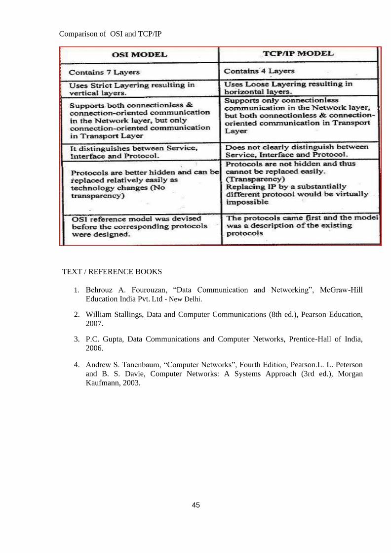
Comparison of OSI and TCP/IP
TEXT / REFERENCE BOOKS
1. Behrouz A. Fourouzan, “Data Communication and Networking”, McGraw-Hill
Education India Pvt. Ltd - New Delhi.
2. William Stallings, Data and Computer Communications (8th ed.), Pearson Education,
2007.
3. P.C. Gupta, Data Communications and Computer Networks, Prentice-Hall of India,
2006.
4. Andrew S. Tanenbaum, “Computer Networks”, Fourth Edition, Pearson.L. L. Peterson
and B. S. Davie, Computer Networks: A Systems Approach (3rd ed.), Morgan
Kaufmann, 2003.
46
QUESTIONS
PART A
1. List the components of data communication.
2. Define Protocol and standards
3. Explain the Classification of Data communications standards
4. What are the network criteria of Data Communication
5. Analyze the Line configuration
6. Define network Topology
7. Explain the types of Transmission mode
8. Organize the different Categories of networks
9. Define Transmission media and give the types
10. Analyze the switching circuit.
11. Differentiate OSI model and TCP/IP Model
PART B
1. Analyze the layers of OSI model and describe the responsibilities of each layer.
2. Distinguish different network topologies and explain each topology with a neat
diagram.
3. Analyze the TCP/IP model with a neat diagram? Explain the functions performed
in each layer.
4. Investigate the different types of Transmission media with a neat diagram.
5. Examine the different Categories of switching circuit.
47
SCHOOL OF COMPUTING
DEPARTMENT OF INFORMATION TECHNOLOGY
UNIT – II – Data communication and networks – SITA1401
48
UNIT II
DATA LIMK LAYER
Error detection and correction– Line Discipline - Flow Control Error control-
Medium Access Control – Ethernet -CSMA/CD - Wireless LAN - CSMA/CA –
IEEE 802.11, Bluetooth
1.Providing services to the network layer:
1 Unacknowledged connectionless service.
Appropriate for low error rate and real-time traffic. Ex: Ethernet
1. Acknowledged connectionless service.
Useful in unreliable channels, WiFi. Ack/Timer/Resend
2. Acknowledged connection-oriented service.
Guarantee frames are received exactly once and in the right order. Appropriate over
long, unreliable links such as a satellite channel or a long- distance telephone circuit
2. Framing: Frames are the streams of bits received from the network layer into
manageable data units. This division of stream of bits is done by Data Link Layer.
3. Physical Addressing: The Data Link layer adds a header to the frame in order to define
physical address of the sender or receiver of the frame, if the frames are to be
distributed to different systems on the network.
4. Flow Control: A receiving node can receive the frames at a faster rate than it can
process the frame. Without flow control, the receiver's buffer can overflow, and
frames can get lost. To overcome this problem, the data link layer uses the flow
control to prevent the sending node on one side of the link from overwhelming the
receiving node on another side of the link. This prevents traffic jam at the receiver
side.
5. Error Control: Error control is achieved by adding a trailer at the end of the frame.
Duplication of frames are also prevented by using this mechanism. Data Link Layers
adds mechanism to prevent duplication of frames.
Error detection: Errors can be introduced by signal attenuation and noise. Data Link
Layer protocol provides a mechanism to detect one or more errors. This is achieved by
adding error detection bits in the frame and then receiving node can perform an error
check.
Error correction: Error correction is similar to the Error detection, except that
receiving node not only detects the errors but also determine where the errors have
occurred in the frame.
6. Access Control: Protocols of this layer determine which of the devices has control over
the link at any given time, when two or more devices are connected to the same link.
7. Reliable delivery: Data Link Layer provides a reliable delivery service, i.e., transmits
the network layer datagram without any error. A reliable delivery service is
accomplished with transmissions and acknowledgements. A data link layer mainly
49
provides the reliable delivery
service over the links as they have higher error rates and they can be corrected locally,
link at which an error occurs rather than forcing to retransmit the data.
8. Half-Duplex & Full-Duplex: In a Full-Duplex mode, both the nodes can transmit the
data at the same time. In a Half-Duplex mode, only one node can transmit the data at
the same time.
FRAMING:
To provide service to the network layer, the data link layer must use the service
provided to it by the physical layer. What the physical layer does is accept a raw bit stream
and attempt to deliver it to the destination. This bit stream is not guaranteed to be error
free. The number of bits received may be less than, equal to, or more than the number of
bits transmitted, and they may have different values. It is up to the data link layer to detect
and, if necessary, correct errors. The usual approach is for the data link layer to break the
bit stream up into discrete frames and compute the checksum for each frame (framing).
When a frame arrives at the destination, the checksum is recomputed. If the newly
computed checksum is different from the one contained in the frame, the data link layer
knows that an error has occurred and takes steps to deal with it (e.g., discarding the bad
frame and possibly also sending back an error report).We will look at four framing
methods:
1. Character count.
2. Flag bytes with byte stuffing.
3. Starting and ending flags, with bit stuffing.
4. Physical layer coding violations.
Character count method uses a field in the header to specify the number of characters in
the frame. When the data link layer at the destination sees the character count, it knows
how many characters follow and hence where the end of the frame is. This technique is
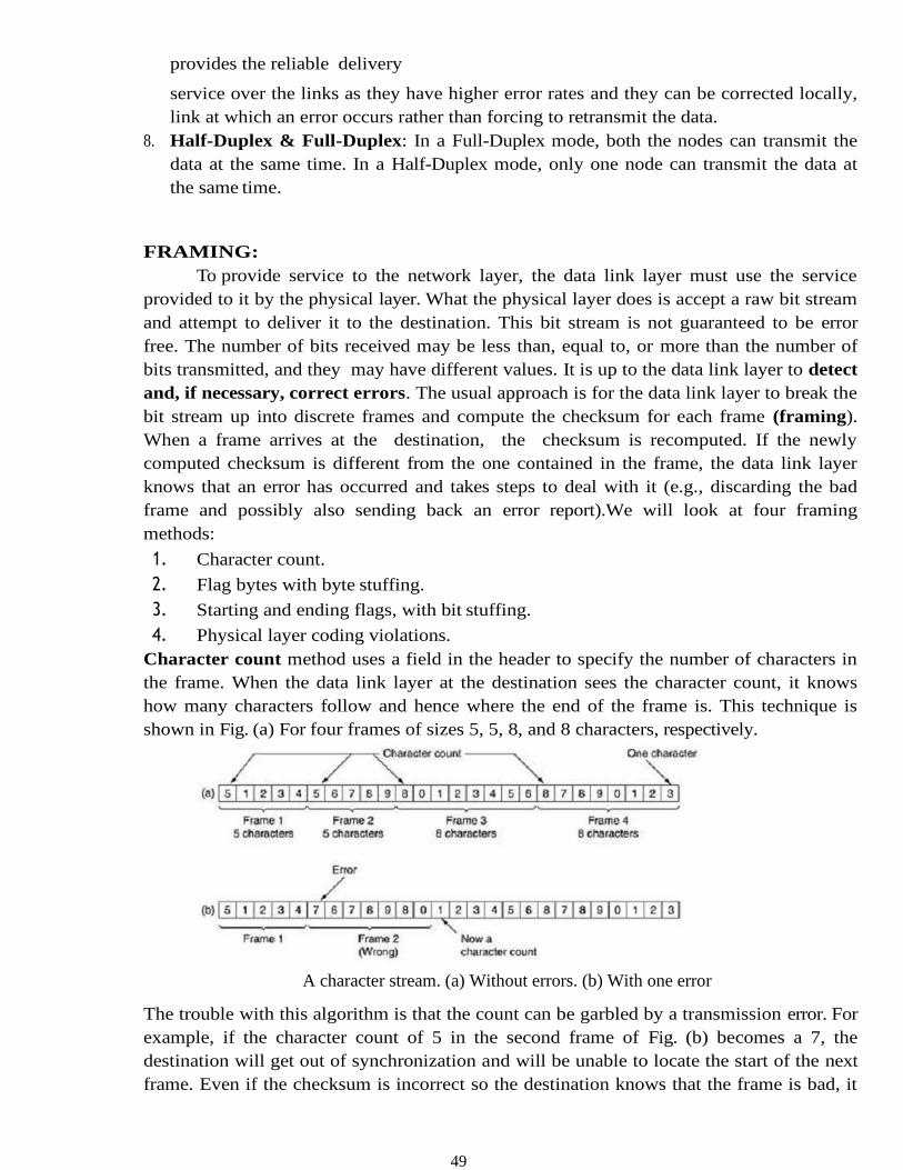
shown in Fig. (a) For four frames of sizes 5, 5, 8, and 8 characters, respectively.
A character stream. (a) Without errors. (b) With one error
The trouble with this algorithm is that the count can be garbled by a transmission error. For
example, if the character count of 5 in the second frame of Fig. (b) becomes a 7, the
destination will get out of synchronization and will be unable to locate the start of the next
frame. Even if the checksum is incorrect so the destination knows that the frame is bad, it
50
still has no way of telling where the next frame starts. Sending a frame back to the source
asking for a retransmission does not help either, since the destination does not know how
many characters to skip over to get to the start of the retransmission. For this reason, the
character count method is rarely used anymore.
Flag bytes with byte stuffing method gets around the problem of resynchronization after
an error by having each frame start and end with special bytes. In the past, the starting and
ending bytes were different, but in recent years most protocols have used the same byte,
called a flag byte, as both the starting and ending delimiter, as shown in Fig. (a) as FLAG.
In this way, if the receiver ever loses synchronization, it can just search for the flag byte to
find the end of the current frame. Two consecutive flag bytes indicate the end of one frame
and start of the next one.
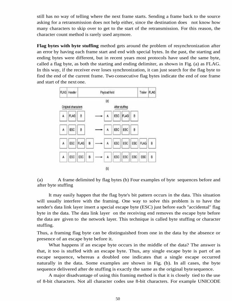
(a) A frame delimited by flag bytes (b) Four examples of byte sequences before and
after byte stuffing
It may easily happen that the flag byte's bit pattern occurs in the data. This situation
will usually interfere with the framing. One way to solve this problem is to have the
sender's data link layer insert a special escape byte (ESC) just before each ''accidental'' flag
byte in the data. The data link layer on the receiving end removes the escape byte before
the data are given to the network layer. This technique is called byte stuffing or character
stuffing.
Thus, a framing flag byte can be distinguished from one in the data by the absence or
presence of an escape byte before it.
What happens if an escape byte occurs in the middle of the data? The answer is
that, it too is stuffed with an escape byte. Thus, any single escape byte is part of an
escape sequence, whereas a doubled one indicates that a single escape occurred
naturally in the data. Some examples are shown in Fig. (b). In all cases, the byte
sequence delivered after de stuffing is exactly the same as the original byte sequence.
A major disadvantage of using this framing method is that it is closely tied to the use
of 8-bit characters. Not all character codes use 8-bit characters. For example UNICODE
51
uses 16-bit characters, so a new technique had to be developed to allow arbitrary sized
characters
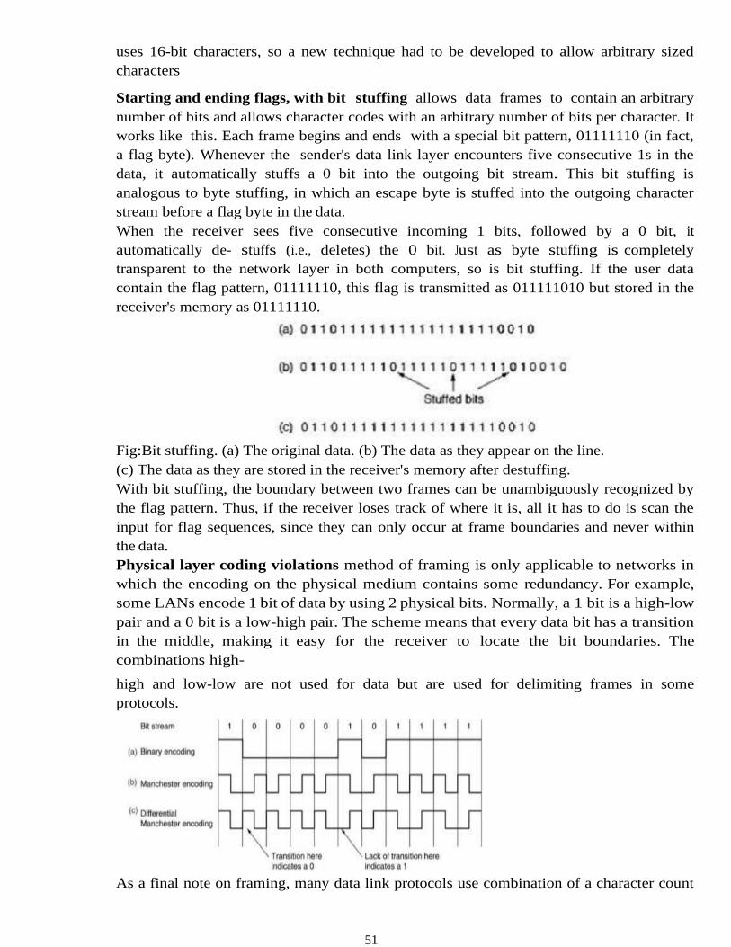
Starting and ending flags, with bit stuffing allows data frames to contain an arbitrary
number of bits and allows character codes with an arbitrary number of bits per character. It
works like this. Each frame begins and ends with a special bit pattern, 01111110 (in fact,
a flag byte). Whenever the sender's data link layer encounters five consecutive 1s in the
data, it automatically stuffs a 0 bit into the outgoing bit stream. This bit stuffing is
analogous to byte stuffing, in which an escape byte is stuffed into the outgoing character
stream before a flag byte in the data.
When the receiver sees five consecutive incoming 1 bits, followed by a 0 bit, it
automatically de- stuffs (i.e., deletes) the 0 bit. Just as byte stuffing is completely
transparent to the network layer in both computers, so is bit stuffing. If the user data
contain the flag pattern, 01111110, this flag is transmitted as 011111010 but stored in the
receiver's memory as 01111110.
Fig:Bit stuffing. (a) The original data. (b) The data as they appear on the line.
(c) The data as they are stored in the receiver's memory after destuffing.
With bit stuffing, the boundary between two frames can be unambiguously recognized by
the flag pattern. Thus, if the receiver loses track of where it is, all it has to do is scan the
input for flag sequences, since they can only occur at frame boundaries and never within
the data.
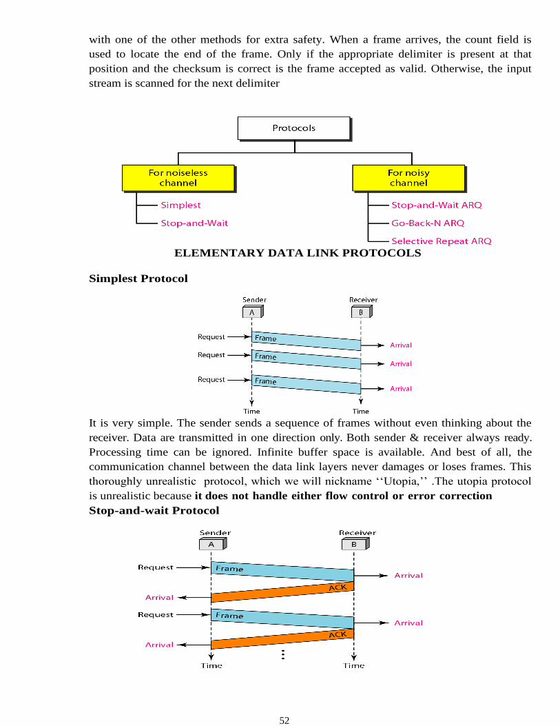
Physical layer coding violations method of framing is only applicable to networks in
which the encoding on the physical medium contains some redundancy. For example,
some LANs encode 1 bit of data by using 2 physical bits. Normally, a 1 bit is a high-low
pair and a 0 bit is a low-high pair. The scheme means that every data bit has a transition
in the middle, making it easy for the receiver to locate the bit boundaries. The
combinations high-
high and low-low are not used for data but are used for delimiting frames in some
protocols.
As a final note on framing, many data link protocols use combination of a character count
52
with one of the other methods for extra safety. When a frame arrives, the count field is
used to locate the end of the frame. Only if the appropriate delimiter is present at that
position and the checksum is correct is the frame accepted as valid. Otherwise, the input
stream is scanned for the next delimiter
ELEMENTARY DATA LINK PROTOCOLS
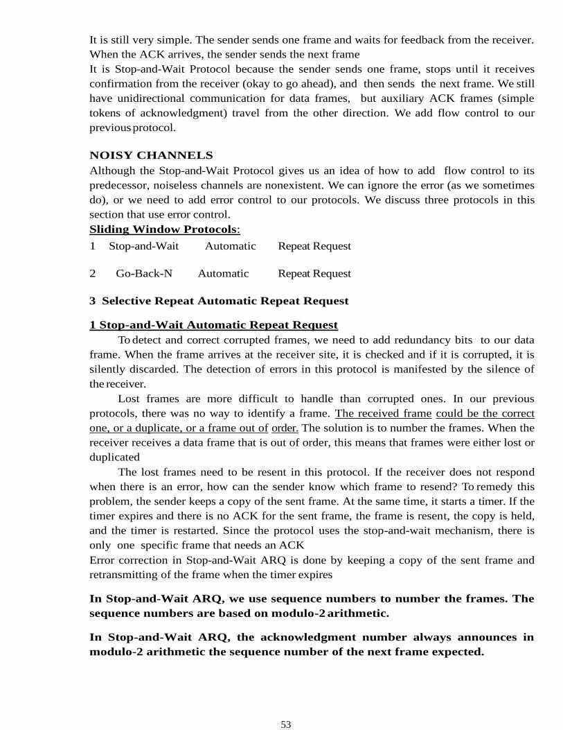
Simplest Protocol
It is very simple. The sender sends a sequence of frames without even thinking about the
receiver. Data are transmitted in one direction only. Both sender & receiver always ready.
Processing time can be ignored. Infinite buffer space is available. And best of all, the
communication channel between the data link layers never damages or loses frames. This
thoroughly unrealistic protocol, which we will nickname ‘‘Utopia,’’ .The utopia protocol
is unrealistic because it does not handle either flow control or error correction
Stop-and-wait Protocol
53
It is still very simple. The sender sends one frame and waits for feedback from the receiver.
When the ACK arrives, the sender sends the next frame
It is Stop-and-Wait Protocol because the sender sends one frame, stops until it receives
confirmation from the receiver (okay to go ahead), and then sends the next frame. We still
have unidirectional communication for data frames, but auxiliary ACK frames (simple
tokens of acknowledgment) travel from the other direction. We add flow control to our
previous protocol.
NOISY CHANNELS
Although the Stop-and-Wait Protocol gives us an idea of how to add flow control to its
predecessor, noiseless channels are nonexistent. We can ignore the error (as we sometimes
do), or we need to add error control to our protocols. We discuss three protocols in this
section that use error control.
Sliding Window Protocols:
1 Stop-and-Wait Automatic Repeat Request
2 Go-Back-N Automatic Repeat Request
3 Selective Repeat Automatic Repeat Request
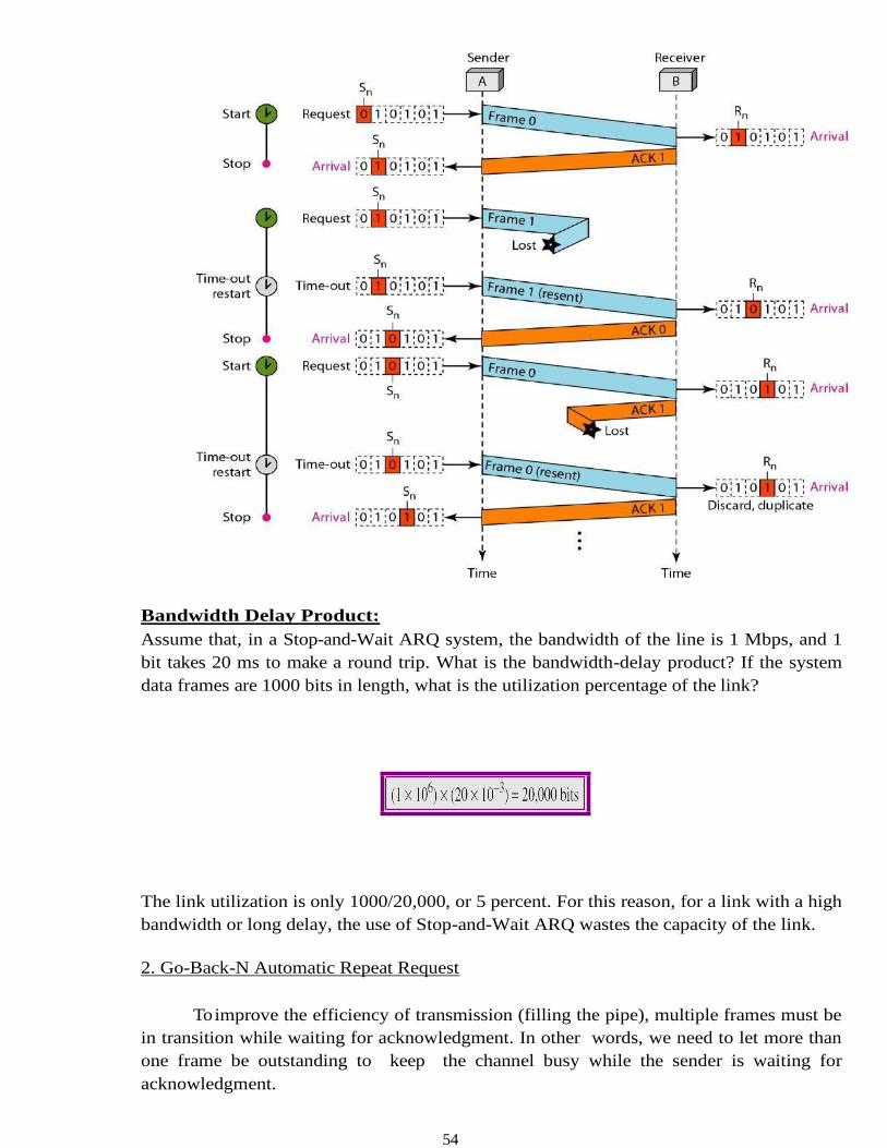
1 Stop-and-Wait Automatic Repeat Request
To detect and correct corrupted frames, we need to add redundancy bits to our data
frame. When the frame arrives at the receiver site, it is checked and if it is corrupted, it is
silently discarded. The detection of errors in this protocol is manifested by the silence of
the receiver.
Lost frames are more difficult to handle than corrupted ones. In our previous
protocols, there was no way to identify a frame. The received frame could be the correct
one, or a duplicate, or a frame out of order. The solution is to number the frames. When the
receiver receives a data frame that is out of order, this means that frames were either lost or
duplicated
The lost frames need to be resent in this protocol. If the receiver does not respond
when there is an error, how can the sender know which frame to resend? To remedy this
problem, the sender keeps a copy of the sent frame. At the same time, it starts a timer. If the
timer expires and there is no ACK for the sent frame, the frame is resent, the copy is held,
and the timer is restarted. Since the protocol uses the stop-and-wait mechanism, there is
only one specific frame that needs an ACK
Error correction in Stop-and-Wait ARQ is done by keeping a copy of the sent frame and
retransmitting of the frame when the timer expires
In Stop-and-Wait ARQ, we use sequence numbers to number the frames. The
sequence numbers are based on modulo-2 arithmetic.
In Stop-and-Wait ARQ, the acknowledgment number always announces in
modulo-2 arithmetic the sequence number of the next frame expected.
54
Bandwidth Delay Product:
Assume that, in a Stop-and-Wait ARQ system, the bandwidth of the line is 1 Mbps, and 1
bit takes 20 ms to make a round trip. What is the bandwidth-delay product? If the system
data frames are 1000 bits in length, what is the utilization percentage of the link?
The link utilization is only 1000/20,000, or 5 percent. For this reason, for a link with a high
bandwidth or long delay, the use of Stop-and-Wait ARQ wastes the capacity of the link.
2. Go-Back-N Automatic Repeat Request
To improve the efficiency of transmission (filling the pipe), multiple frames must be
in transition while waiting for acknowledgment. In other words, we need to let more than
one frame be outstanding to keep the channel busy while the sender is waiting for
acknowledgment.
55
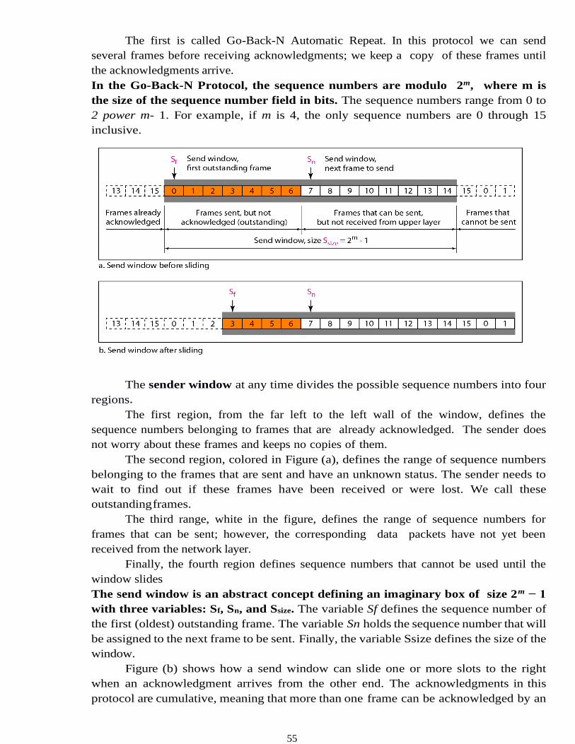
The first is called Go-Back-N Automatic Repeat. In this protocol we can send
several frames before receiving acknowledgments; we keep a copy of these frames until
the acknowledgments arrive.
In the Go-Back-N Protocol, the sequence numbers are modulo 2m, where m is
the size of the sequence number field in bits. The sequence numbers range from 0 to
2 power m- 1. For example, if m is 4, the only sequence numbers are 0 through 15
inclusive.
The sender window at any time divides the possible sequence numbers into four
regions.
The first region, from the far left to the left wall of the window, defines the
sequence numbers belonging to frames that are already acknowledged. The sender does
not worry about these frames and keeps no copies of them.
The second region, colored in Figure (a), defines the range of sequence numbers
belonging to the frames that are sent and have an unknown status. The sender needs to
wait to find out if these frames have been received or were lost. We call these
outstanding frames.
The third range, white in the figure, defines the range of sequence numbers for
frames that can be sent; however, the corresponding data packets have not yet been
received from the network layer.
Finally, the fourth region defines sequence numbers that cannot be used until the
window slides
The send window is an abstract concept defining an imaginary box of size 2m − 1
with three variables: Sf, Sn, and Ssize. The variable Sf defines the sequence number of
the first (oldest) outstanding frame. The variable Sn holds the sequence number that will
be assigned to the next frame to be sent. Finally, the variable Ssize defines the size of the
window.
Figure (b) shows how a send window can slide one or more slots to the right
when an acknowledgment arrives from the other end. The acknowledgments in this
protocol are cumulative, meaning that more than one frame can be acknowledged by an
56
ACK frame. In Figure, frames 0, I, and 2 are acknowledged, so the window has slide to
the right three slots. Note that the value of Sf is 3 because frame 3 is now the first
outstanding frame.The send window can slide one or more slots when a valid
acknowledgment arrives.
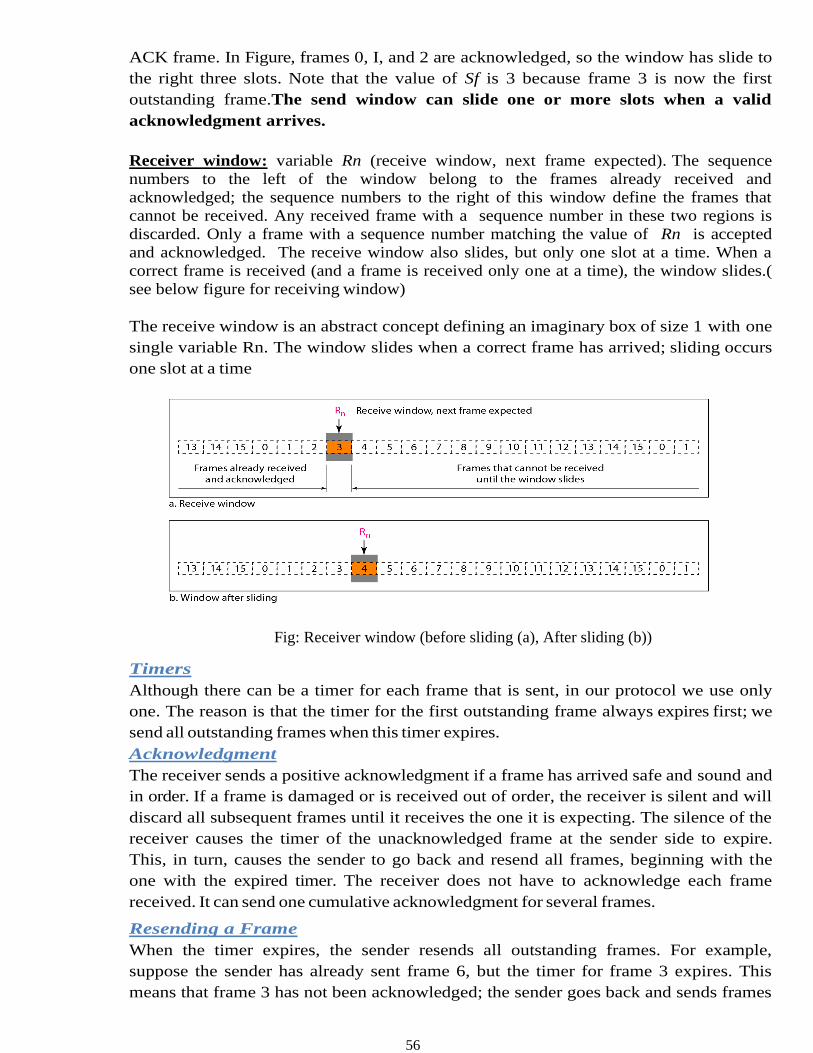
Receiver window: variable Rn (receive window, next frame expected). The sequence
numbers to the left of the window belong to the frames already received and
acknowledged; the sequence numbers to the right of this window define the frames that
cannot be received. Any received frame with a sequence number in these two regions is
discarded. Only a frame with a sequence number matching the value of Rn is accepted
and acknowledged. The receive window also slides, but only one slot at a time. When a
correct frame is received (and a frame is received only one at a time), the window slides.(
see below figure for receiving window)
The receive window is an abstract concept defining an imaginary box of size 1 with one
single variable Rn. The window slides when a correct frame has arrived; sliding occurs
one slot at a time
Fig: Receiver window (before sliding (a), After sliding (b))
Timers
Although there can be a timer for each frame that is sent, in our protocol we use only
one. The reason is that the timer for the first outstanding frame always expires first; we
send all outstanding frames when this timer expires.
Acknowledgment
The receiver sends a positive acknowledgment if a frame has arrived safe and sound and
in order. If a frame is damaged or is received out of order, the receiver is silent and will
discard all subsequent frames until it receives the one it is expecting. The silence of the
receiver causes the timer of the unacknowledged frame at the sender side to expire.
This, in turn, causes the sender to go back and resend all frames, beginning with the
one with the expired timer. The receiver does not have to acknowledge each frame
received. It can send one cumulative acknowledgment for several frames.
Resending a Frame
When the timer expires, the sender resends all outstanding frames. For example,
suppose the sender has already sent frame 6, but the timer for frame 3 expires. This
means that frame 3 has not been acknowledged; the sender goes back and sends frames
57
3,4,5, and 6 again. That is why the protocol is called Go-Back-N ARQ.
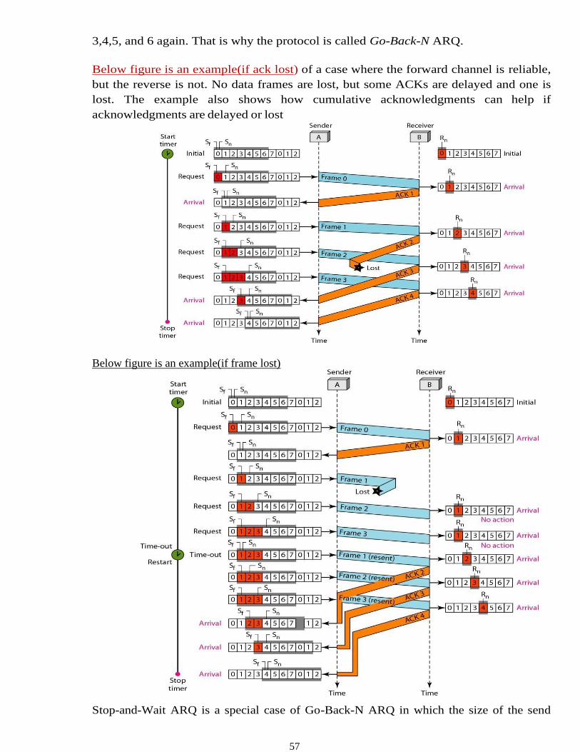
Below figure is an example(if ack lost) of a case where the forward channel is reliable,
but the reverse is not. No data frames are lost, but some ACKs are delayed and one is
lost. The example also shows how cumulative acknowledgments can help if
acknowledgments are delayed or lost
Below figure is an example(if frame lost)
Stop-and-Wait ARQ is a special case of Go-Back-N ARQ in which the size of the send
58
window is 1.
3 Selective Repeat Automatic Repeat Request
In Go-Back-N ARQ, The receiver keeps track of only one variable, and there is no
need to buffer out-of- order frames; they are simply discarded. However, this protocol
is very inefficient for a noisy link.
In a noisy link a frame has a higher probability of damage, which means the resending of
multiple frames. This resending uses up the bandwidth and slows down the transmission.
For noisy links, there is another mechanism that does not resend N frames when just
one frame is damaged; only the damaged frame is resent. This mechanism is called
Selective Repeat ARQ.
It is more efficient for noisy links, but the processing at the receiver is more complex.
Sender Window (explain go-back N sender window concept (before & after sliding.)
The only difference in sender window between Go-back N and Selective Repeat is
Window size)
Receiver window
The receiver window in Selective Repeat is totally different from the one in Go Back-N.
First, the size of the receive window is the same as the size of the send window (2m-1).
The Selective Repeat Protocol allows as many frames as the size of the receiver window
to arrive out of order and be kept until there is a set of in- order frames to be delivered to
the network layer. Because the sizes of the send window and receive window are the same,
all the frames in the send frame can arrive out of order and be stored until they can be
delivered. However the receiver never delivers packets out of order to the network layer.
Above Figure shows the receive window. Those slots inside the window that are colored
define frames that have arrived out of order and are waiting for their neighbors to arrive
before delivery to the network layer.
In Selective Repeat ARQ, the size of the sender and receiver window must be at most one-
half of 2m
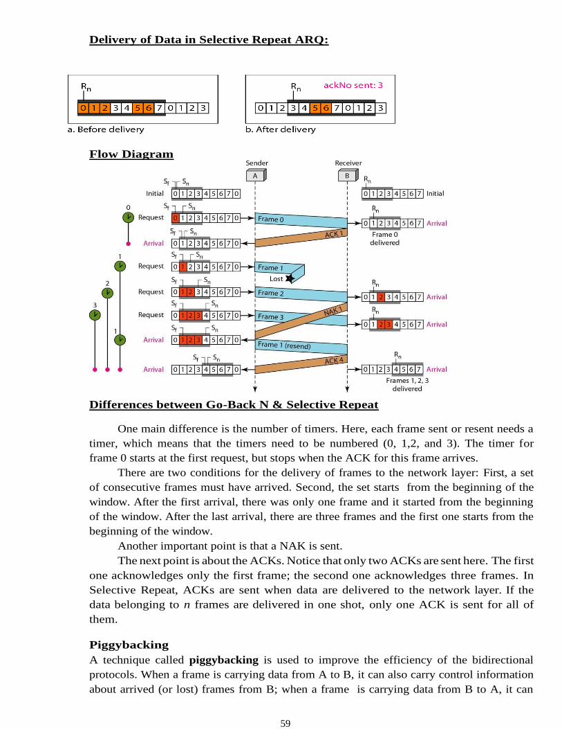
59
Delivery of Data in Selective Repeat ARQ:
Flow Diagram
Differences between Go-Back N & Selective Repeat
One main difference is the number of timers. Here, each frame sent or resent needs a
timer, which means that the timers need to be numbered (0, 1,2, and 3). The timer for
frame 0 starts at the first request, but stops when the ACK for this frame arrives.
There are two conditions for the delivery of frames to the network layer: First, a set
of consecutive frames must have arrived. Second, the set starts from the beginning of the
window. After the first arrival, there was only one frame and it started from the beginning
of the window. After the last arrival, there are three frames and the first one starts from the
beginning of the window.
Another important point is that a NAK is sent.
The next point is about the ACKs. Notice that only two ACKs are sent here. The first
one acknowledges only the first frame; the second one acknowledges three frames. In
Selective Repeat, ACKs are sent when data are delivered to the network layer. If the
data belonging to n frames are delivered in one shot, only one ACK is sent for all of
them.
Piggybacking
A technique called piggybacking is used to improve the efficiency of the bidirectional
protocols. When a frame is carrying data from A to B, it can also carry control information
about arrived (or lost) frames from B; when a frame is carrying data from B to A, it can
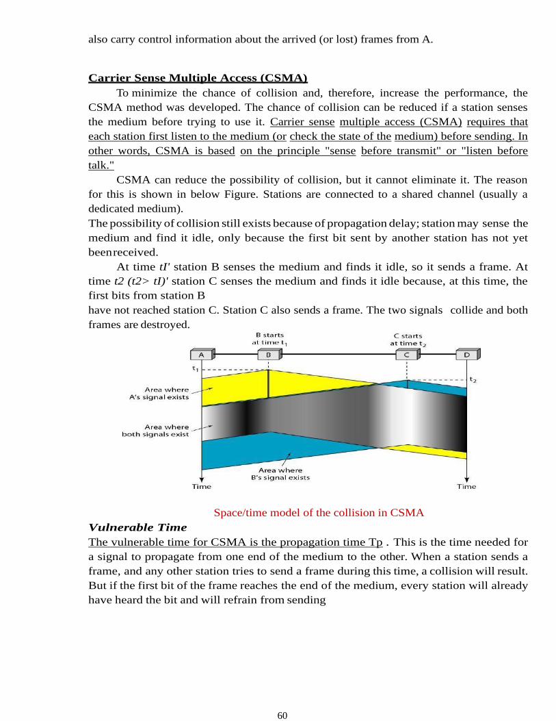
60
also carry control information about the arrived (or lost) frames from A.
Carrier Sense Multiple Access (CSMA)
To minimize the chance of collision and, therefore, increase the performance, the
CSMA method was developed. The chance of collision can be reduced if a station senses
the medium before trying to use it. Carrier sense multiple access (CSMA) requires that
each station first listen to the medium (or check the state of the medium) before sending. In
other words, CSMA is based on the principle "sense before transmit" or "listen before
talk."
CSMA can reduce the possibility of collision, but it cannot eliminate it. The reason
for this is shown in below Figure. Stations are connected to a shared channel (usually a
dedicated medium).
The possibility of collision still exists because of propagation delay; station may sense the
medium and find it idle, only because the first bit sent by another station has not yet
been received.
At time tI' station B senses the medium and finds it idle, so it sends a frame. At
time t2 (t2> tI)' station C senses the medium and finds it idle because, at this time, the
first bits from station B
have not reached station C. Station C also sends a frame. The two signals collide and both
frames are destroyed.
Space/time model of the collision in CSMA
Vulnerable Time
The vulnerable time for CSMA is the propagation time Tp . This is the time needed for
a signal to propagate from one end of the medium to the other. When a station sends a
frame, and any other station tries to send a frame during this time, a collision will result.
But if the first bit of the frame reaches the end of the medium, every station will already
have heard the bit and will refrain from sending
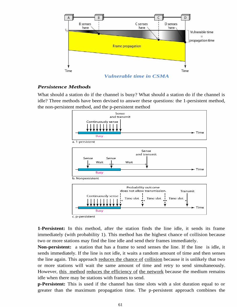
61
Vulnerable time in CSMA
Persistence Methods
What should a station do if the channel is busy? What should a station do if the channel is
idle? Three methods have been devised to answer these questions: the 1-persistent method,
the non-persistent method, and the p-persistent method
1-Persistent: In this method, after the station finds the line idle, it sends its frame
immediately (with probability 1). This method has the highest chance of collision because
two or more stations may find the line idle and send their frames immediately.
Non-persistent: a station that has a frame to send senses the line. If the line is idle, it
sends immediately. If the line is not idle, it waits a random amount of time and then senses
the line again. This approach reduces the chance of collision because it is unlikely that two
or more stations will wait the same amount of time and retry to send simultaneously.
However, this method reduces the efficiency of the network because the medium remains
idle when there may be stations with frames to send.
p-Persistent: This is used if the channel has time slots with a slot duration equal to or
greater than the maximum propagation time. The p-persistent approach combines the
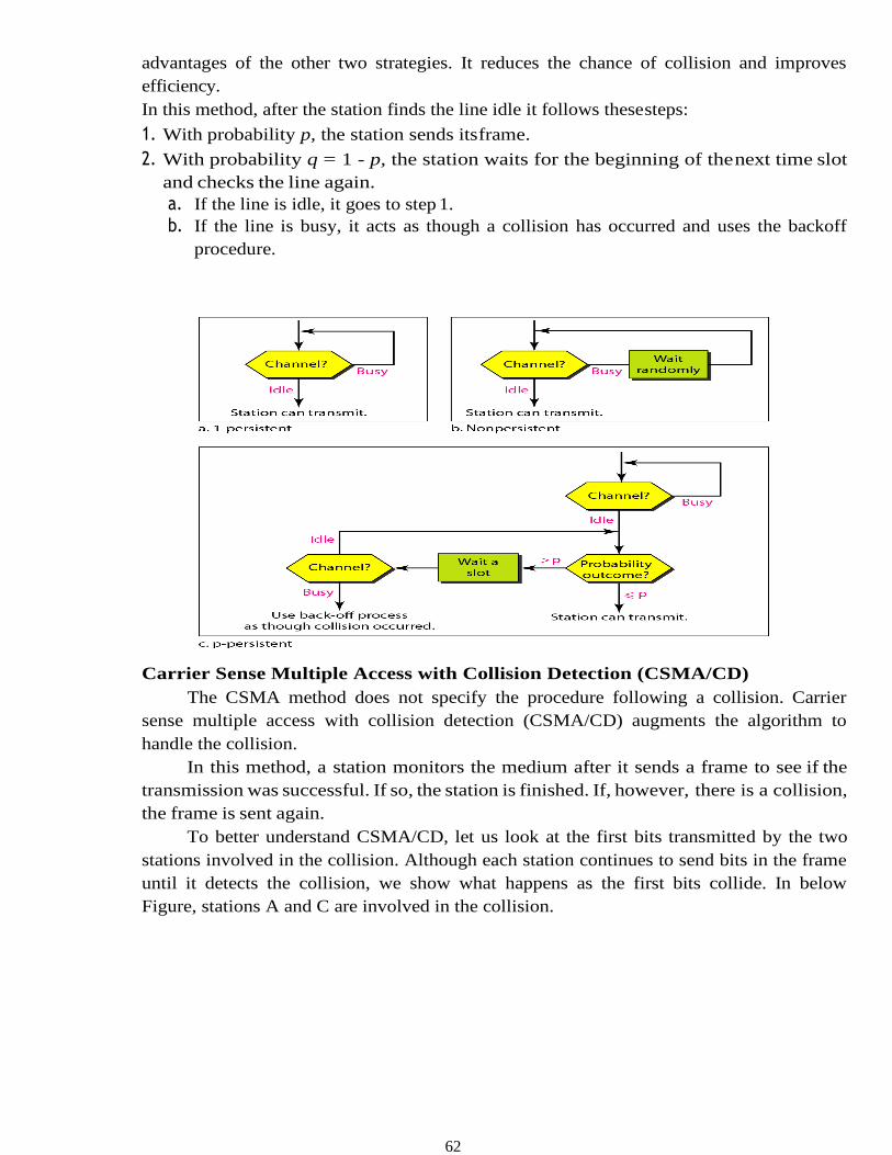
62
advantages of the other two strategies. It reduces the chance of collision and improves
efficiency.
In this method, after the station finds the line idle it follows these steps:
1. With probability p, the station sends its frame.
2. With probability q = 1 - p, the station waits for the beginning of the next time slot
and checks the line again.
a. If the line is idle, it goes to step 1.
b. If the line is busy, it acts as though a collision has occurred and uses the backoff
procedure.
a.
Carrier Sense Multiple Access with Collision Detection (CSMA/CD)
The CSMA method does not specify the procedure following a collision. Carrier
sense multiple access with collision detection (CSMA/CD) augments the algorithm to
handle the collision.
In this method, a station monitors the medium after it sends a frame to see if the
transmission was successful. If so, the station is finished. If, however, there is a collision,
the frame is sent again.
To better understand CSMA/CD, let us look at the first bits transmitted by the two
stations involved in the collision. Although each station continues to send bits in the frame
until it detects the collision, we show what happens as the first bits collide. In below
Figure, stations A and C are involved in the collision.
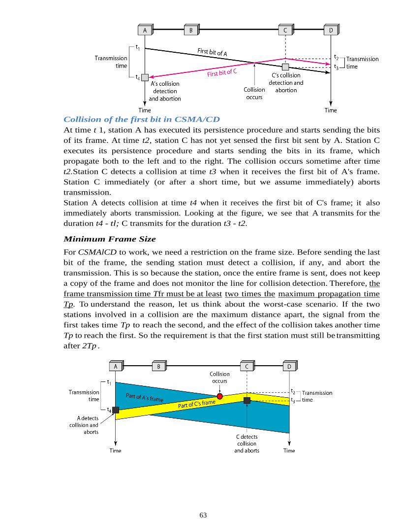
63
Collision of the first bit in CSMA/CD
At time t 1, station A has executed its persistence procedure and starts sending the bits
of its frame. At time t2, station C has not yet sensed the first bit sent by A. Station C
executes its persistence procedure and starts sending the bits in its frame, which
propagate both to the left and to the right. The collision occurs sometime after time
t2.Station C detects a collision at time t3 when it receives the first bit of A's frame.
Station C immediately (or after a short time, but we assume immediately) aborts
transmission.
Station A detects collision at time t4 when it receives the first bit of C's frame; it also
immediately aborts transmission. Looking at the figure, we see that A transmits for the
duration t4 - tl; C transmits for the duration t3 - t2.
Minimum Frame Size
For CSMAlCD to work, we need a restriction on the frame size. Before sending the last
bit of the frame, the sending station must detect a collision, if any, and abort the
transmission. This is so because the station, once the entire frame is sent, does not keep
a copy of the frame and does not monitor the line for collision detection. Therefore, the
frame transmission time Tfr must be at least two times the maximum propagation time
Tp. To understand the reason, let us think about the worst-case scenario. If the two
stations involved in a collision are the maximum distance apart, the signal from the
first takes time Tp to reach the second, and the effect of the collision takes another time
Tp to reach the first. So the requirement is that the first station must still be transmitting
after 2Tp .
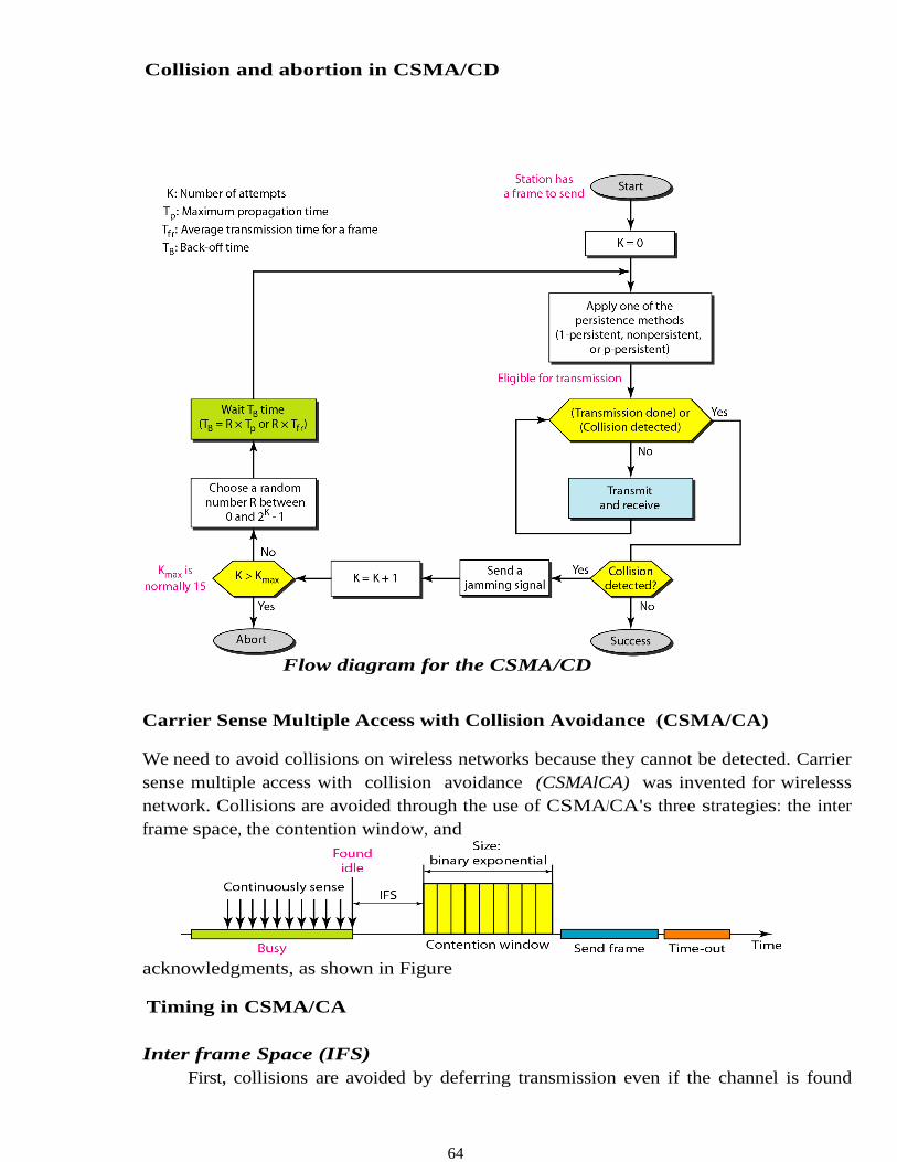
64
Collision and abortion in CSMA/CD
Flow diagram for the CSMA/CD
Carrier Sense Multiple Access with Collision Avoidance (CSMA/CA)
We need to avoid collisions on wireless networks because they cannot be detected. Carrier
sense multiple access with collision avoidance (CSMAlCA) was invented for wirelesss
network. Collisions are avoided through the use of CSMA/CA's three strategies: the inter
frame space, the contention window, and
acknowledgments, as shown in Figure
Timing in CSMA/CA
Inter frame Space (IFS)
First, collisions are avoided by deferring transmission even if the channel is found
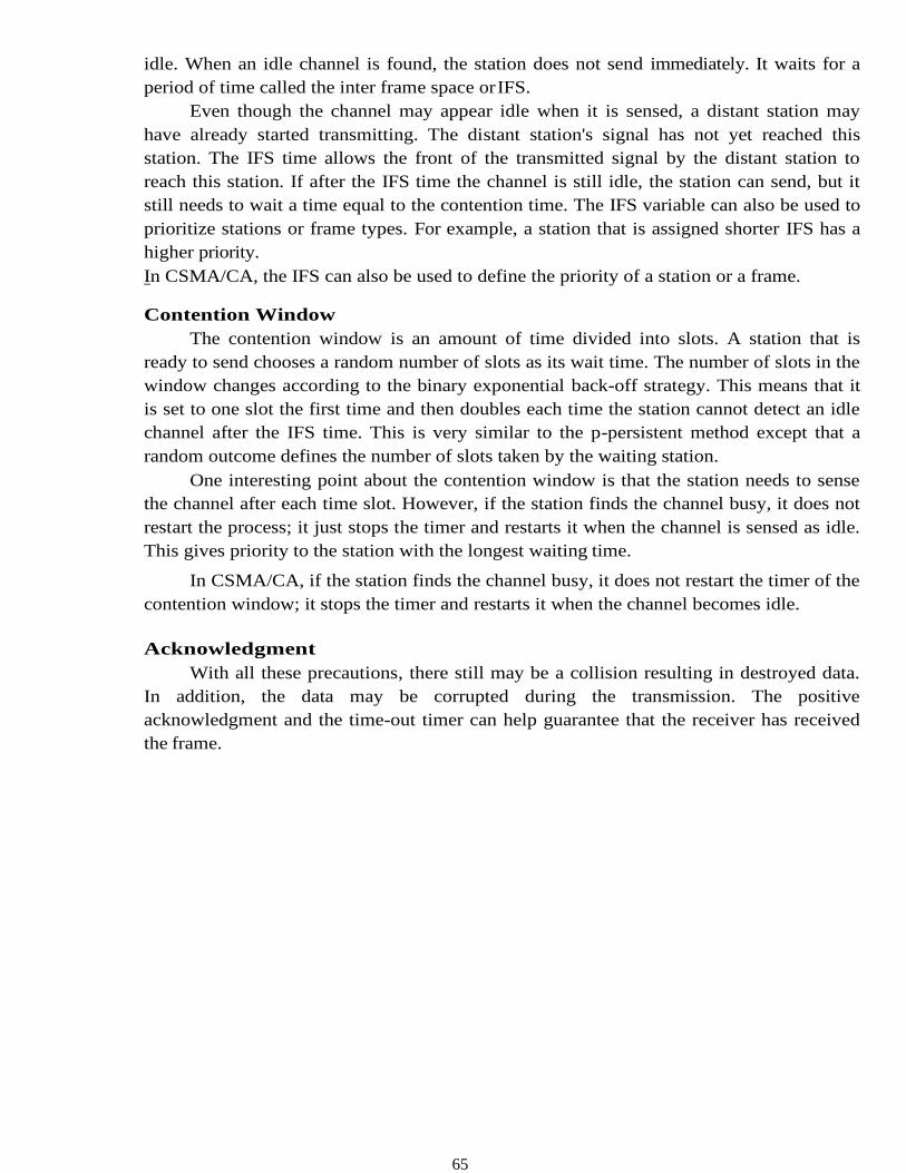
65
idle. When an idle channel is found, the station does not send immediately. It waits for a
period of time called the inter frame space or IFS.
Even though the channel may appear idle when it is sensed, a distant station may
have already started transmitting. The distant station's signal has not yet reached this
station. The IFS time allows the front of the transmitted signal by the distant station to
reach this station. If after the IFS time the channel is still idle, the station can send, but it
still needs to wait a time equal to the contention time. The IFS variable can also be used to
prioritize stations or frame types. For example, a station that is assigned shorter IFS has a
higher priority.
In CSMA/CA, the IFS can also be used to define the priority of a station or a frame.
Contention Window
The contention window is an amount of time divided into slots. A station that is
ready to send chooses a random number of slots as its wait time. The number of slots in the
window changes according to the binary exponential back-off strategy. This means that it
is set to one slot the first time and then doubles each time the station cannot detect an idle
channel after the IFS time. This is very similar to the p-persistent method except that a
random outcome defines the number of slots taken by the waiting station.
One interesting point about the contention window is that the station needs to sense
the channel after each time slot. However, if the station finds the channel busy, it does not
restart the process; it just stops the timer and restarts it when the channel is sensed as idle.
This gives priority to the station with the longest waiting time.
In CSMA/CA, if the station finds the channel busy, it does not restart the timer of the
contention window; it stops the timer and restarts it when the channel becomes idle.
Acknowledgment
With all these precautions, there still may be a collision resulting in destroyed data.
In addition, the data may be corrupted during the transmission. The positive
acknowledgment and the time-out timer can help guarantee that the receiver has received
the frame.
66
This is the CSMA protocol with collision avoidance.
• The station ready to transmit, senses the line by using one of the persistent strategies.
• As soon as it finds the line to be idle, the station waits for an IFS (Inter frame
space) amount of time.
• If then waits for some random time and sends the frame.
• After sending the frame, it sets a timer and waits for the acknowledgement from the
receiver.
• If the acknowledgement is received before expiry of the timer, then the
transmission is successful.
• But if the transmitting station does not receive
the expected acknowledgement before the timer expiry then it increments the
back off parameter, waits for the back off time and re senses the line
Error Detection
Error
A condition when the receiver’s information does not matches with the sender’s
information. During transmission, digital signals suffer from noise that can introduce
errors in the binary bits travelling from sender to receiver. That means a 0 bit may
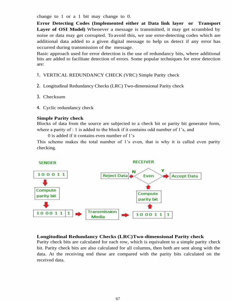
67
change to 1 or a 1 bit may change to 0.
Error Detecting Codes (Implemented either at Data link layer or Transport
Layer of OSI Model) Whenever a message is transmitted, it may get scrambled by
noise or data may get corrupted. To avoid this, we use error-detecting codes which are
additional data added to a given digital message to help us detect if any error has
occurred during transmission of the message.
Basic approach used for error detection is the use of redundancy bits, where additional
bits are added to facilitate detection of errors. Some popular techniques for error detection
are:
1. VERTICAL REDUNDANCY CHECK (VRC) Simple Parity check
2. Longitudinal Redundancy Checks (LRC) Two-dimensional Parity check
3. Checksum
4. Cyclic redundancy check
Simple Parity check
Blocks of data from the source are subjected to a check bit or parity bit generator form,
where a parity of : 1 is added to the block if it contains odd number of 1’s, and
0 is added if it contains even number of 1’s
This scheme makes the total number of 1’s even, that is why it is called even parity
checking.
Longitudinal Redundancy Checks (LRC)Two-dimensional Parity check
Parity check bits are calculated for each row, which is equivalent to a simple parity check
bit. Parity check bits are also calculated for all columns, then both are sent along with the
data. At the receiving end these are compared with the parity bits calculated on the
received data.
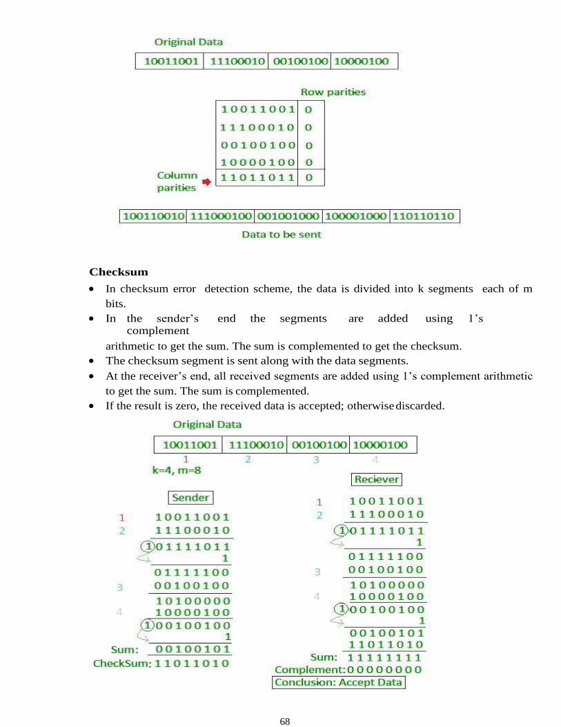
68
Checksum
• In checksum error detection scheme, the data is divided into k segments each of m
bits.
• In the sender’s end the segments are added using 1’s complement
arithmetic to get the sum. The sum is complemented to get the checksum.
• The checksum segment is sent along with the data segments.
• At the receiver’s end, all received segments are added using 1’s complement arithmetic
to get the sum. The sum is complemented.
• If the result is zero, the received data is accepted; otherwise discarded.
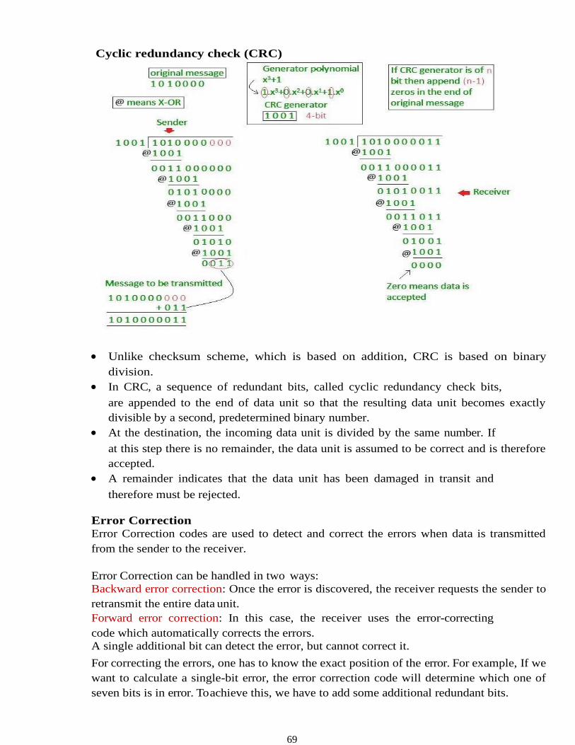
69
Cyclic redundancy check (CRC)
• Unlike checksum scheme, which is based on addition, CRC is based on binary
division.
• In CRC, a sequence of redundant bits, called cyclic redundancy check bits,
are appended to the end of data unit so that the resulting data unit becomes exactly
divisible by a second, predetermined binary number.
• At the destination, the incoming data unit is divided by the same number. If
at this step there is no remainder, the data unit is assumed to be correct and is therefore
accepted.
• A remainder indicates that the data unit has been damaged in transit and
therefore must be rejected.
Error Correction
Error Correction codes are used to detect and correct the errors when data is transmitted
from the sender to the receiver.
Error Correction can be handled in two ways:
Backward error correction: Once the error is discovered, the receiver requests the sender to
retransmit the entire data unit.
Forward error correction: In this case, the receiver uses the error-correcting
code which automatically corrects the errors.
A single additional bit can detect the error, but cannot correct it.
For correcting the errors, one has to know the exact position of the error. For example, If we
want to calculate a single-bit error, the error correction code will determine which one of
seven bits is in error. To achieve this, we have to add some additional redundant bits.
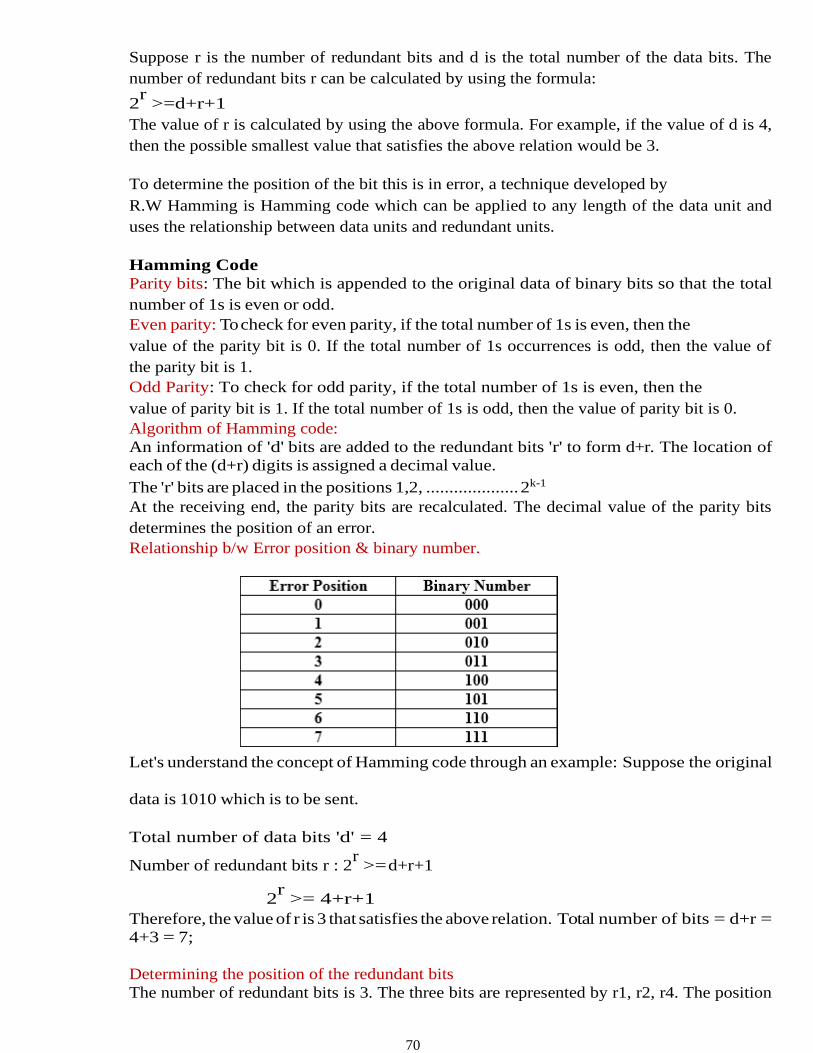
70
Suppose r is the number of redundant bits and d is the total number of the data bits. The
number of redundant bits r can be calculated by using the formula:
2r
>=d+r+1
The value of r is calculated by using the above formula. For example, if the value of d is 4,
then the possible smallest value that satisfies the above relation would be 3.
To determine the position of the bit this is in error, a technique developed by
R.W Hamming is Hamming code which can be applied to any length of the data unit and
uses the relationship between data units and redundant units.
Hamming Code
Parity bits: The bit which is appended to the original data of binary bits so that the total
number of 1s is even or odd.
Even parity: To check for even parity, if the total number of 1s is even, then the
value of the parity bit is 0. If the total number of 1s occurrences is odd, then the value of
the parity bit is 1.
Odd Parity: To check for odd parity, if the total number of 1s is even, then the
value of parity bit is 1. If the total number of 1s is odd, then the value of parity bit is 0.
Algorithm of Hamming code:
An information of 'd' bits are added to the redundant bits 'r' to form d+r. The location of
each of the (d+r) digits is assigned a decimal value.
The 'r' bits are placed in the positions 1,2, .................... 2k-1
At the receiving end, the parity bits are recalculated. The decimal value of the parity bits
determines the position of an error.
Relationship b/w Error position & binary number.
Let's understand the concept of Hamming code through an example: Suppose the original
data is 1010 which is to be sent.
Total number of data bits 'd' = 4
Number of redundant bits r : 2r
>= d+r+1
2r
>= 4+r+1
Therefore, the value of r is 3 that satisfies the above relation. Total number of bits = d+r =
4+3 = 7;
Determining the position of the redundant bits
The number of redundant bits is 3. The three bits are represented by r1, r2, r4. The position
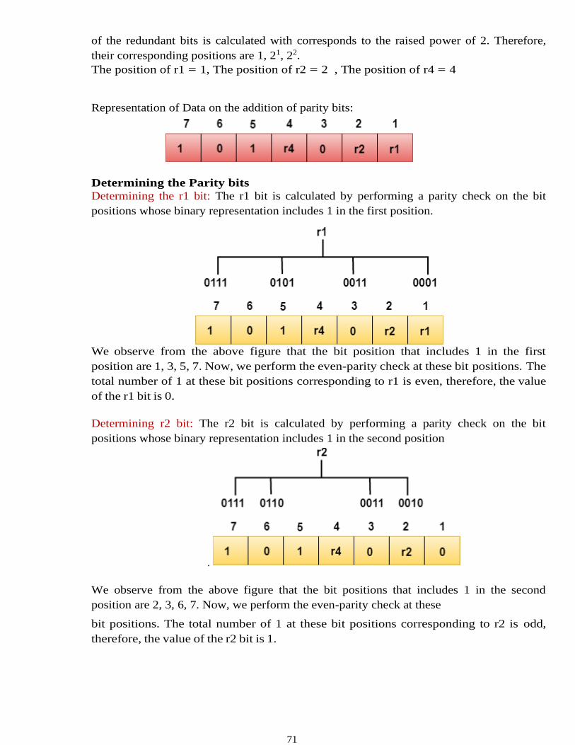
71
of the redundant bits is calculated with corresponds to the raised power of 2. Therefore,
their corresponding positions are 1, 21, 22.
The position of r1 = 1, The position of r2 = 2 , The position of r4 = 4
Representation of Data on the addition of parity bits:
Determining the Parity bits
Determining the r1 bit: The r1 bit is calculated by performing a parity check on the bit
positions whose binary representation includes 1 in the first position.
We observe from the above figure that the bit position that includes 1 in the first
position are 1, 3, 5, 7. Now, we perform the even-parity check at these bit positions. The
total number of 1 at these bit positions corresponding to r1 is even, therefore, the value
of the r1 bit is 0.
Determining r2 bit: The r2 bit is calculated by performing a parity check on the bit
positions whose binary representation includes 1 in the second position
.
We observe from the above figure that the bit positions that includes 1 in the second
position are 2, 3, 6, 7. Now, we perform the even-parity check at these
bit positions. The total number of 1 at these bit positions corresponding to r2 is odd,
therefore, the value of the r2 bit is 1.
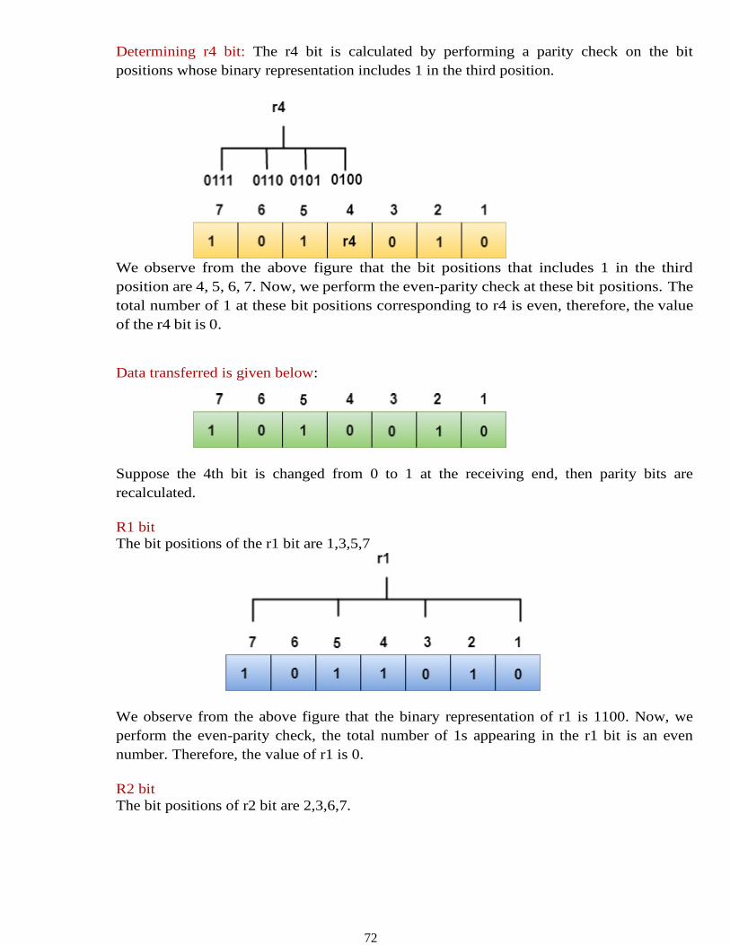
72
Determining r4 bit: The r4 bit is calculated by performing a parity check on the bit
positions whose binary representation includes 1 in the third position.
We observe from the above figure that the bit positions that includes 1 in the third
position are 4, 5, 6, 7. Now, we perform the even-parity check at these bit positions. The
total number of 1 at these bit positions corresponding to r4 is even, therefore, the value
of the r4 bit is 0.
Data transferred is given below:
Suppose the 4th bit is changed from 0 to 1 at the receiving end, then parity bits are
recalculated.
R1 bit
The bit positions of the r1 bit are 1,3,5,7
We observe from the above figure that the binary representation of r1 is 1100. Now, we
perform the even-parity check, the total number of 1s appearing in the r1 bit is an even
number. Therefore, the value of r1 is 0.
R2 bit
The bit positions of r2 bit are 2,3,6,7.
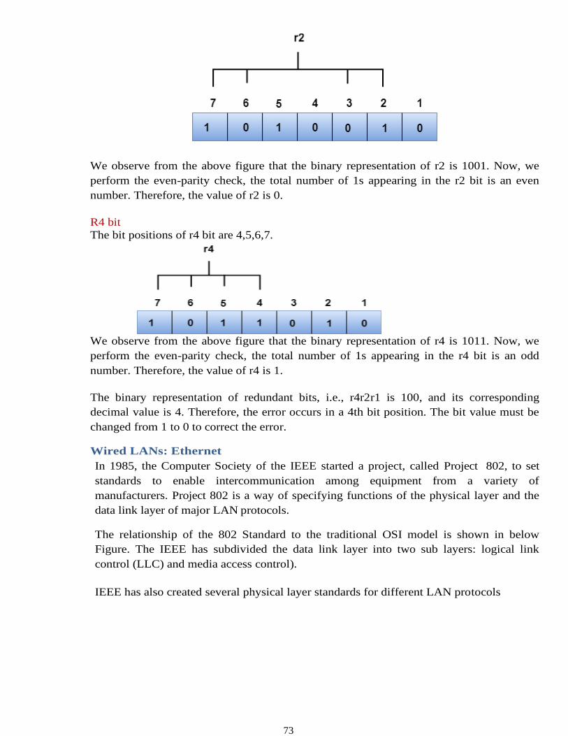
73
We observe from the above figure that the binary representation of r2 is 1001. Now, we
perform the even-parity check, the total number of 1s appearing in the r2 bit is an even
number. Therefore, the value of r2 is 0.
R4 bit
The bit positions of r4 bit are 4,5,6,7.
We observe from the above figure that the binary representation of r4 is 1011. Now, we
perform the even-parity check, the total number of 1s appearing in the r4 bit is an odd
number. Therefore, the value of r4 is 1.
The binary representation of redundant bits, i.e., r4r2r1 is 100, and its corresponding
decimal value is 4. Therefore, the error occurs in a 4th bit position. The bit value must be
changed from 1 to 0 to correct the error.
Wired LANs: Ethernet
In 1985, the Computer Society of the IEEE started a project, called Project 802, to set
standards to enable intercommunication among equipment from a variety of
manufacturers. Project 802 is a way of specifying functions of the physical layer and the
data link layer of major LAN protocols.
The relationship of the 802 Standard to the traditional OSI model is shown in below
Figure. The IEEE has subdivided the data link layer into two sub layers: logical link
control (LLC) and media access control).
IEEE has also created several physical layer standards for different LAN protocols
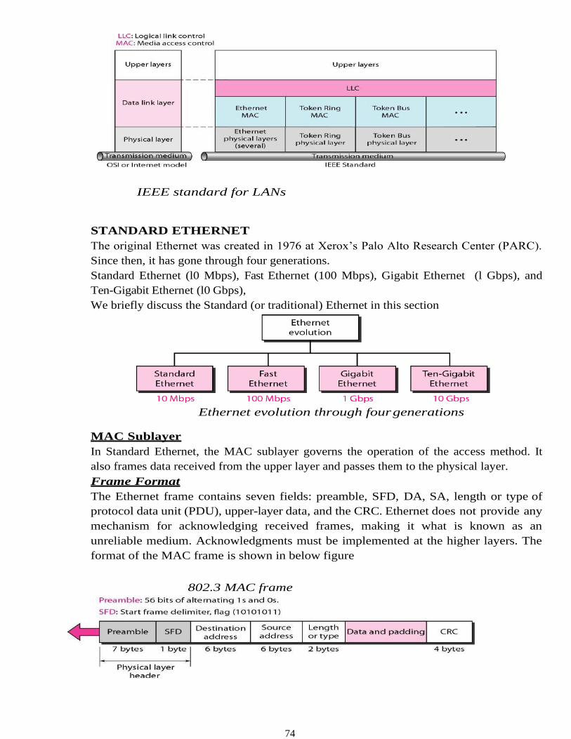
74
IEEE standard for LANs
STANDARD ETHERNET
The original Ethernet was created in 1976 at Xerox’s Palo Alto Research Center (PARC).
Since then, it has gone through four generations.
Standard Ethernet (l0 Mbps), Fast Ethernet (100 Mbps), Gigabit Ethernet (l Gbps), and
Ten-Gigabit Ethernet (l0 Gbps),
We briefly discuss the Standard (or traditional) Ethernet in this section
Ethernet evolution through four generations
MAC Sublayer
In Standard Ethernet, the MAC sublayer governs the operation of the access method. It
also frames data received from the upper layer and passes them to the physical layer.
Frame Format
The Ethernet frame contains seven fields: preamble, SFD, DA, SA, length or type of
protocol data unit (PDU), upper-layer data, and the CRC. Ethernet does not provide any
mechanism for acknowledging received frames, making it what is known as an
unreliable medium. Acknowledgments must be implemented at the higher layers. The
format of the MAC frame is shown in below figure
802.3 MAC frame
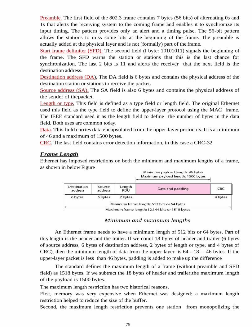
75
Preamble. The first field of the 802.3 frame contains 7 bytes (56 bits) of alternating 0s and
1s that alerts the receiving system to the coming frame and enables it to synchronize its
input timing. The pattern provides only an alert and a timing pulse. The 56-bit pattern
allows the stations to miss some bits at the beginning of the frame. The preamble is
actually added at the physical layer and is not (formally) part of the frame.
Start frame delimiter (SFD). The second field (l byte: 10101011) signals the beginning of
the frame. The SFD warns the station or stations that this is the last chance for
synchronization. The last 2 bits is 11 and alerts the receiver that the next field is the
destination address.
Destination address (DA). The DA field is 6 bytes and contains the physical address of the
destination station or stations to receive the packet.
Source address (SA). The SA field is also 6 bytes and contains the physical address of
the sender of the packet.
Length or type. This field is defined as a type field or length field. The original Ethernet
used this field as the type field to define the upper-layer protocol using the MAC frame.
The IEEE standard used it as the length field to define the number of bytes in the data
field. Both uses are common today.
Data. This field carries data encapsulated from the upper-layer protocols. It is a minimum
of 46 and a maximum of 1500 bytes.
CRC. The last field contains error detection information, in this case a CRC-32
Frame Length
Ethernet has imposed restrictions on both the minimum and maximum lengths of a frame,
as shown in below Figure
Minimum and maximum lengths
An Ethernet frame needs to have a minimum length of 512 bits or 64 bytes. Part of
this length is the header and the trailer. If we count 18 bytes of header and trailer (6 bytes
of source address, 6 bytes of destination address, 2 bytes of length or type, and 4 bytes of
CRC), then the minimum length of data from the upper layer is 64 - 18 = 46 bytes. If the
upper-layer packet is less than 46 bytes, padding is added to make up the difference
The standard defines the maximum length of a frame (without preamble and SFD
field) as 1518 bytes. If we subtract the 18 bytes of header and trailer,the maximum length
of the payload is 1500 bytes.
The maximum length restriction has two historical reasons.
First, memory was very expensive when Ethernet was designed: a maximum length
restriction helped to reduce the size of the buffer.
Second, the maximum length restriction prevents one station from monopolizing the
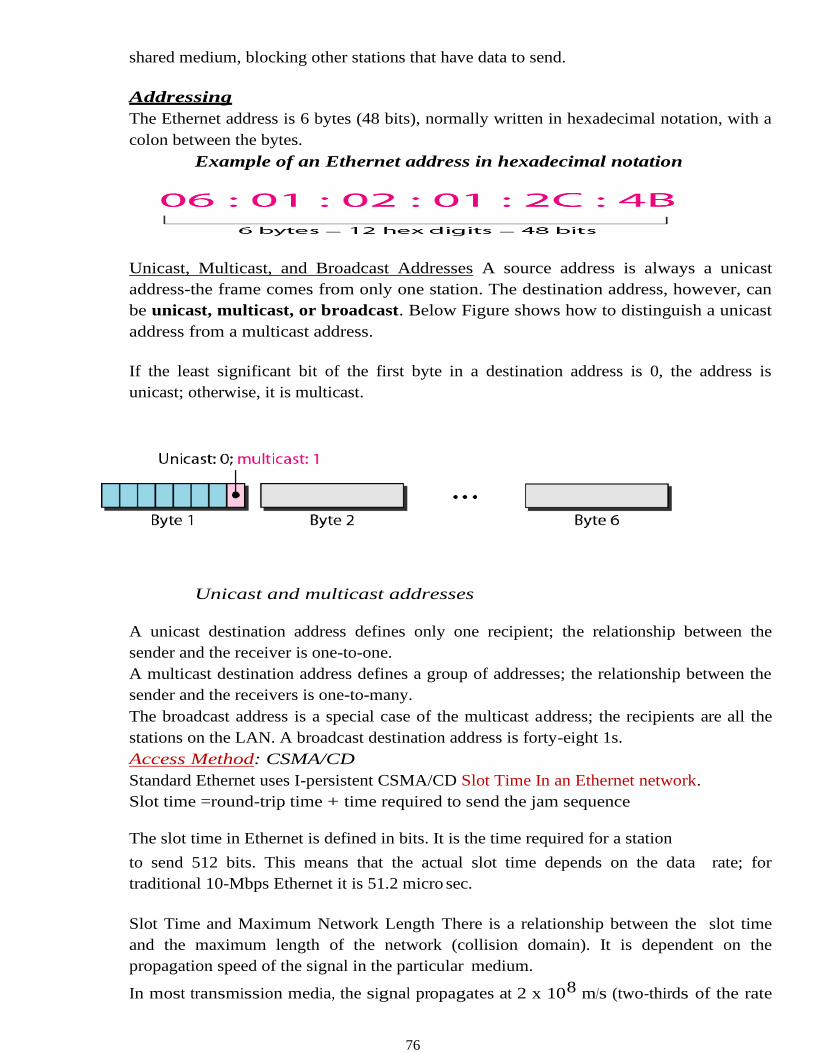
76
shared medium, blocking other stations that have data to send.
Addressing
The Ethernet address is 6 bytes (48 bits), normally written in hexadecimal notation, with a
colon between the bytes.
Example of an Ethernet address in hexadecimal notation
Unicast, Multicast, and Broadcast Addresses A source address is always a unicast
address-the frame comes from only one station. The destination address, however, can
be unicast, multicast, or broadcast. Below Figure shows how to distinguish a unicast
address from a multicast address.
If the least significant bit of the first byte in a destination address is 0, the address is
unicast; otherwise, it is multicast.
Unicast and multicast addresses
A unicast destination address defines only one recipient; the relationship between the
sender and the receiver is one-to-one.
A multicast destination address defines a group of addresses; the relationship between the
sender and the receivers is one-to-many.
The broadcast address is a special case of the multicast address; the recipients are all the
stations on the LAN. A broadcast destination address is forty-eight 1s.
Access Method: CSMA/CD
Standard Ethernet uses I-persistent CSMA/CD Slot Time In an Ethernet network.
Slot time =round-trip time + time required to send the jam sequence
The slot time in Ethernet is defined in bits. It is the time required for a station
to send 512 bits. This means that the actual slot time depends on the data rate; for
traditional 10-Mbps Ethernet it is 51.2 micro sec.
Slot Time and Maximum Network Length There is a relationship between the slot time
and the maximum length of the network (collision domain). It is dependent on the
propagation speed of the signal in the particular medium.
In most transmission media, the signal propagates at 2 x 10⁸ m/s (two-thirds of the rate
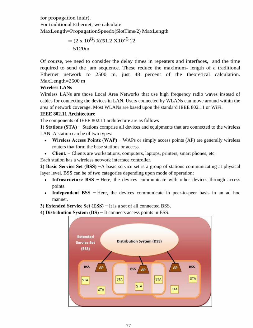
77
for propagation in air).
For traditional Ethernet, we calculate
MaxLength=PropagationSpeedx(SlotTime/2) MaxLength
= (2 x 108) X(51.2 X10-6 )/2
= 5120m
Of course, we need to consider the delay times in repeaters and interfaces, and the time
required to send the jam sequence. These reduce the maximum- length of a traditional
Ethernet network to 2500 m, just 48 percent of the theoretical calculation.
MaxLength=2500 m
Wireless LANs
Wireless LANs are those Local Area Networks that use high frequency radio waves instead of
cables for connecting the devices in LAN. Users connected by WLANs can move around within the
area of network coverage. Most WLANs are based upon the standard IEEE 802.11 or WiFi.
IEEE 802.11 Architecture
The components of IEEE 802.11 architecture are as follows
1) Stations (STA) − Stations comprise all devices and equipments that are connected to the wireless
LAN. A station can be of two types:
• Wireless Access Pointz (WAP) − WAPs or simply access points (AP) are generally wireless
routers that form the base stations or access.
• Client. − Clients are workstations, computers, laptops, printers, smart phones, etc.
Each station has a wireless network interface controller.
2) Basic Service Set (BSS) −A basic service set is a group of stations communicating at physical
layer level. BSS can be of two categories depending upon mode of operation:
• Infrastructure BSS − Here, the devices communicate with other devices through access
points.
• Independent BSS − Here, the devices communicate in peer-to-peer basis in an ad hoc
manner.
3) Extended Service Set (ESS) − It is a set of all connected BSS.
4) Distribution System (DS) − It connects access points in ESS.
78
Advantages of WLANs
• They provide clutter free homes, offices and other networked places.
• The LANs are scalable in nature, i.e. devices may be added or removed from the network at a
greater ease than wired LANs.
• The system is portable within the network coverage and access to the network is not bounded
by the length of the cables.
• Installation and setup is much easier than wired counterparts.
• The equipment and setup costs are reduced.
Disadvantages of WLANs
• Since radio waves are used for communications, the signals are noisier with more interference
from nearby systems.
• Greater care is needed for encrypting information. Also, they are more prone to errors. So,
they require greater bandwidth than the wired LANs.
• WLANs are slower than wired LANs.
Bluetooth
Bluetooth wireless technology is a short range communications technology intended to replace
the cables connecting portable unit and maintaining high levels of security. Bluetooth technology
is based on Ad-hoc technology also known as Ad-hoc Pico nets, which is a local area network
with a very limited coverage.
Piconets and Scatternets
Bluetooth enabled electronic devices connect and communicate wirelessly through shortrange
devices known as Piconets. Bluetooth devices exist in small ad-hoc configurations with the
ability to act either as master or slave the specification allows a mechanism
for master and slave to switch their roles. Point to point configuration with one master and one
slave is the simplest configuration.
When more than two Bluetooth devices communicate with one another, this is called
a PICONET. A Piconet can contain up to seven slaves clustered around a single master. The
device that initializes establishment of the Piconet becomes the master.
The master is responsible for transmission control by dividing the network into a series of time
slots amongst the network members, as a part of time division multiplexing scheme which is
shown below.
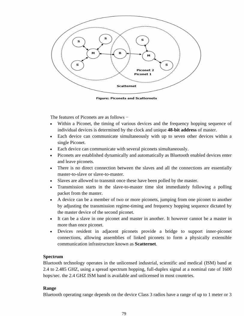
79
The features of Piconets are as follows −
• Within a Piconet, the timing of various devices and the frequency hopping sequence of
individual devices is determined by the clock and unique 48-bit address of master.
• Each device can communicate simultaneously with up to seven other devices within a
single Piconet.
• Each device can communicate with several piconets simultaneously.
• Piconets are established dynamically and automatically as Bluetooth enabled devices enter
and leave piconets.
• There is no direct connection between the slaves and all the connections are essentially
master-to-slave or slave-to-master.
• Slaves are allowed to transmit once these have been polled by the master.
• Transmission starts in the slave-to-master time slot immediately following a polling
packet from the master.
• A device can be a member of two or more piconets, jumping from one piconet to another
by adjusting the transmission regime-timing and frequency hopping sequence dictated by
the master device of the second piconet.
• It can be a slave in one piconet and master in another. It however cannot be a master in
more than once piconet.
• Devices resident in adjacent piconets provide a bridge to support inner-piconet
connections, allowing assemblies of linked piconets to form a physically extensible
communication infrastructure known as Scatternet.
Spectrum
Bluetooth technology operates in the unlicensed industrial, scientific and medical (ISM) band at
2.4 to 2.485 GHZ, using a spread spectrum hopping, full-duplex signal at a nominal rate of 1600
hops/sec. the 2.4 GHZ ISM band is available and unlicensed in most countries.
Range
Bluetooth operating range depends on the device Class 3 radios have a range of up to 1 meter or 3
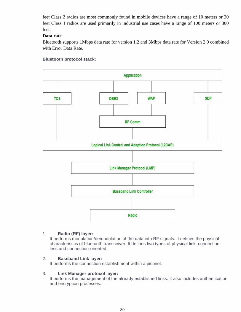
80
feet Class 2 radios are most commonly found in mobile devices have a range of 10 meters or 30
feet Class 1 radios are used primarily in industrial use cases have a range of 100 meters or 300
feet.
Data rate
Bluetooth supports 1Mbps data rate for version 1.2 and 3Mbps data rate for Version 2.0 combined
with Error Data Rate.
Bluetooth protocol stack:
1. Radio (RF) layer: It performs modulation/demodulation of the data into RF signals. It defines the physical characteristics of bluetooth transceiver. It defines two types of physical link: connection-less and connection-oriented.
2. Baseband Link layer: It performs the connection establishment within a piconet.
3. Link Manager protocol layer: It performs the management of the already established links. It also includes authentication and encryption processes.
81
4. Logical Link Control and Adaption protocol layer: It is also known as the heart of the bluetooth protocol stack. It allows the communication between upper and lower layers of the bluetooth protocol stack. It packages the data packets received from upper layers into the form expected by lower layers. It also performs the segmentation and multiplexing.
5. SDP layer: It is short for Service Discovery Protocol. It allows to discover the services available on another bluetooth enabled device.
6. RF comm layer: It is short for Radio Frontend Component. It provides serial interface with WAP and OBEX.
7. OBEX: It is short for Object Exchange. It is a communication protocol to exchange objects between 2 devices.
8. WAP: It is short for Wireless Access Protocol. It is used for internet access.
9. TCS: It is short for Telephony Control Protocol. It provides telephony service.
10. Application layer: It enables the user to interact with the application.
Advantages: • Low cost. • Easy to use. • It can also penetrate through walls. • It creates an adhoc connection immediately without any wires. • It is used for voice and data transfer. Disadvantages: • It can be hacked and hence, less secure. • It has slow data transfer rate: 3 Mbps. • It has small range: 10 meters.
TEXT / REFERENCE BOOKS
1. Behrouz A. Fourouzan, “Data Communication and Networking”, Fifth Edition, McGraw-Hill
Education India Pvt. Ltd -
New Delhi., 2013.
2. William Stallings, Data and Computer Communications (8th ed.), Pearson Education, 2007.
3. P.C. Gupta, Data Communications and Computer Networks, Prentice-Hall of India, 2006.
4. Andrew S. Tanenbaum, “Computer Networks”, Fifth Edition, Pearson, 2011.
5. L. L. Peterson and B. S. Davie, Computer Networks: A Systems Approach (3rd ed.), Morgan
Kaufmann, 2003.
82
Questions
Part A
1. Examine the design issues of data link layer
2. Differentiate connectionless and connection oriented service
3. Define Framing
4. Explain Bit stuffing
5. Define flow control
6. List advantage and disadvantages of Wireless LAN
7. List the application of Ethernet
8. Differentiate CSMA/CD and CSMA/CA
9. Differences between Go-Back N & Selective Repeat
10. Draw the frame format of MAC layer
Part B
1. Examine the Error control techniques in data link layer.
2. Examine elementary protocols of data link layer
3. Organize the structure of CSMA/CD
4. Organize the structure of CSMA/CA
5. Construct a hamming code if message to be transmitted is 1011001. Also depict how it will
detect & correct an error if the received message is 10101101110.
6. Construct the structure of Bluetooth
7. Expalin the working of IEEE 802.11
83
UNIT – III – Data communication and Computer networks – SITA1401
SCHOOL OF COMPUTING
DEPARTMENT OF INFORMATION TECHNOLOGY
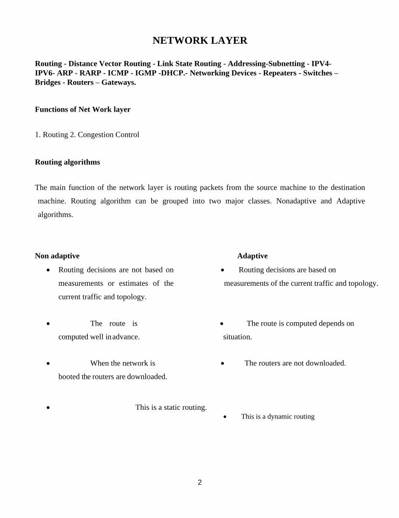
2
NETWORK LAYER
Routing - Distance Vector Routing - Link State Routing - Addressing-Subnetting - IPV4-
IPV6- ARP - RARP - ICMP - IGMP -DHCP.- Networking Devices - Repeaters - Switches –
Bridges - Routers – Gateways.
Functions of Net Work layer
1. Routing 2. Congestion Control
Routing algorithms
The main function of the network layer is routing packets from the source machine to the destination
machine. Routing algorithm can be grouped into two major classes. Nonadaptive and Adaptive
algorithms.
Non adaptive Adaptive
• Routing decisions are not based on
measurements or estimates of the
current traffic and topology.
• Routing decisions are based on
measurements of the current traffic and topology.
• The route is
computed well in advance.
• The route is computed depends on
situation.
• When the network is
booted the routers are downloaded.
• The routers are not downloaded.
• This is a static routing.
• This is a dynamic routing
3
Classification of a Routing algorithm
Distance Vector Routing Algorithm
▪ The Distance vector algorithm is iterative, asynchronous and distributed.
o Distributed: It is distributed in that each node receives information from one or more of
its directly attached neighbors, performs calculation and then distributes the result back to its
neighbors.
o Iterative: It is iterative in that its process continues until no more
▪ information is available to be exchanged between neighbors.
o Asynchronous: It does not require that all of its nodes operate
▪ in the lock step with each other.
➢ The Distance vector algorithm is a dynamic algorithm.
➢ It is mainly used in ARPANET, and RIP.
➢ Each router maintains a distance table known as Vector.
Three Keys to understand the working of Distance Vector Routing Algorithm
Knowledge about the whole network: Each router shares its knowledge through the
entire network. The Router sends its collected knowledge about the network to its neighbors.
Routing only to neighbors: The router sends its knowledge about the network to only
those routers which have direct links. The router sends whatever it has about the network
through the ports. The information is received by the router and uses the information to
update its own routing table.
Information sharing at regular intervals: Within 30 seconds, the router sends the
information to the neighboring routers.
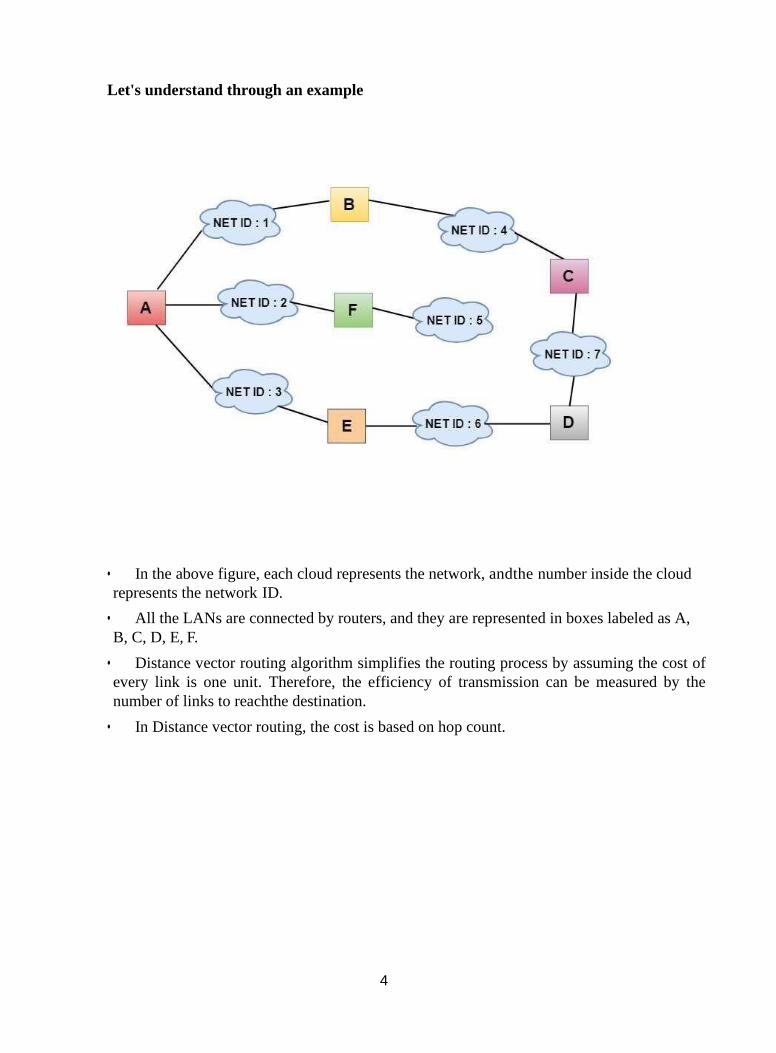
4
Let's understand through an example
• In the above figure, each cloud represents the network, andthe number inside the cloud
represents the network ID.
• All the LANs are connected by routers, and they are represented in boxes labeled as A,
B, C, D, E, F.
• Distance vector routing algorithm simplifies the routing process by assuming the cost of
every link is one unit. Therefore, the efficiency of transmission can be measured by the
number of links to reachthe destination.
• In Distance vector routing, the cost is based on hop count.
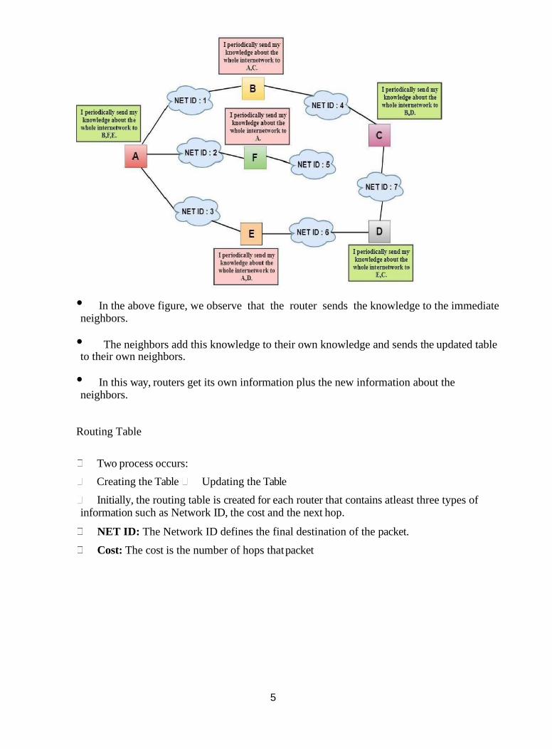
5
• In the above figure, we observe that the router sends the knowledge to the immediate neighbors.
• The neighbors add this knowledge to their own knowledge and sends the updated table to their own neighbors.
• In this way, routers get its own information plus the new information about the neighbors.
Routing Table
Two process occurs:
Creating the Table Updating the Table
Initially, the routing table is created for each router that contains atleast three types of information such as Network ID, the cost and the next hop.
NET ID: The Network ID defines the final destination of the packet.
Cost: The cost is the number of hops that packet
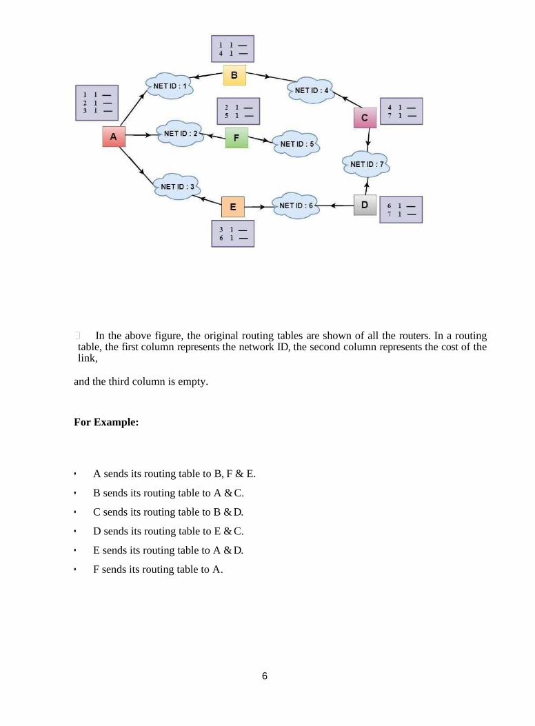
6
In the above figure, the original routing tables are shown of all the routers. In a routing table, the first column represents the network ID, the second column represents the cost of the link,
and the third column is empty.
For Example:
• A sends its routing table to B, F & E.
• B sends its routing table to A & C.
• C sends its routing table to B & D.
• D sends its routing table to E & C.
• E sends its routing table to A & D.
• F sends its routing table to A.
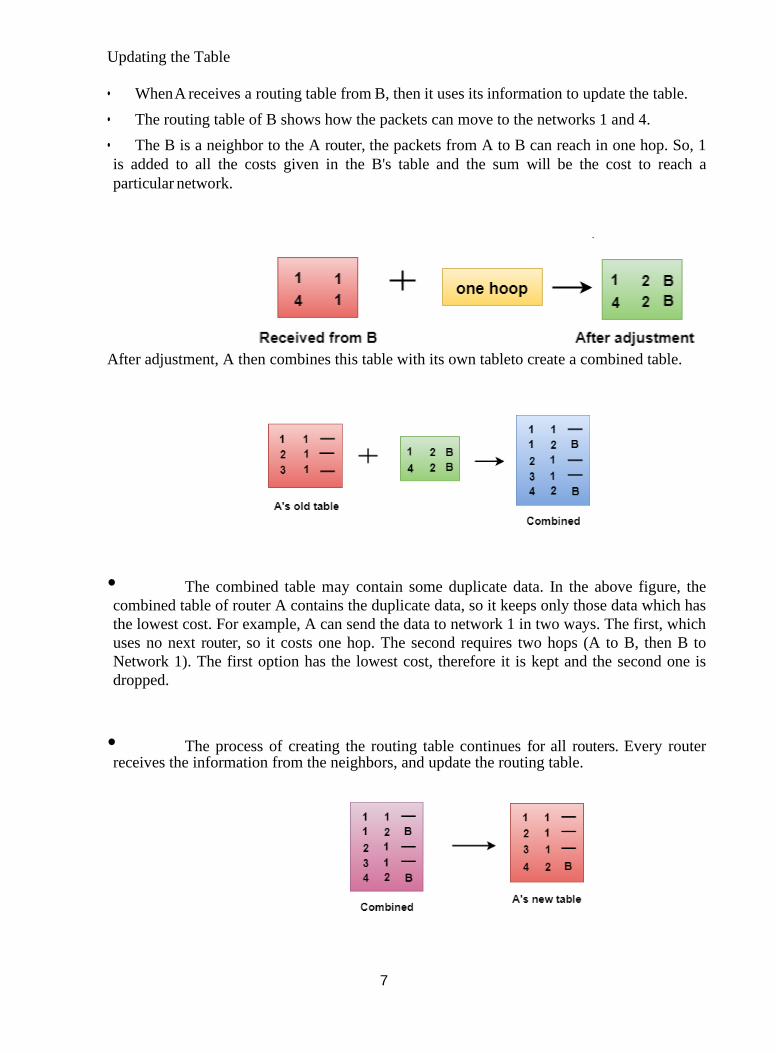
7
Updating the Table
• When A receives a routing table from B, then it uses its information to update the table.
• The routing table of B shows how the packets can move to the networks 1 and 4.
• The B is a neighbor to the A router, the packets from A to B can reach in one hop. So, 1
is added to all the costs given in the B's table and the sum will be the cost to reach a
particular network.
After adjustment, A then combines this table with its own tableto create a combined table.
• The combined table may contain some duplicate data. In the above figure, the
combined table of router A contains the duplicate data, so it keeps only those data which has
the lowest cost. For example, A can send the data to network 1 in two ways. The first, which
uses no next router, so it costs one hop. The second requires two hops (A to B, then B to
Network 1). The first option has the lowest cost, therefore it is kept and the second one is
dropped.
• The process of creating the routing table continues for all routers. Every router receives the information from the neighbors, and update the routing table.
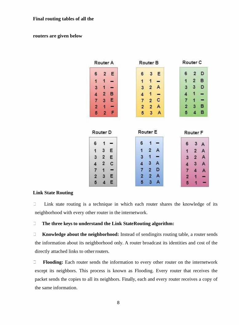
8
Final routing tables of all the
routers are given below
Link State Routing
Link state routing is a technique in which each router shares the knowledge of its
neighborhood with every other router in the internetwork.
The three keys to understand the Link State Routing algorithm:
Knowledge about the neighborhood: Instead of sendingits routing table, a router sends
the information about its neighborhood only. A router broadcast its identities and cost of the
directly attached links to other routers.
Flooding: Each router sends the information to every other router on the internetwork
except its neighbors. This process is known as Flooding. Every router that receives the
packet sends the copies to all its neighbors. Finally, each and every router receives a copy of
the same information.
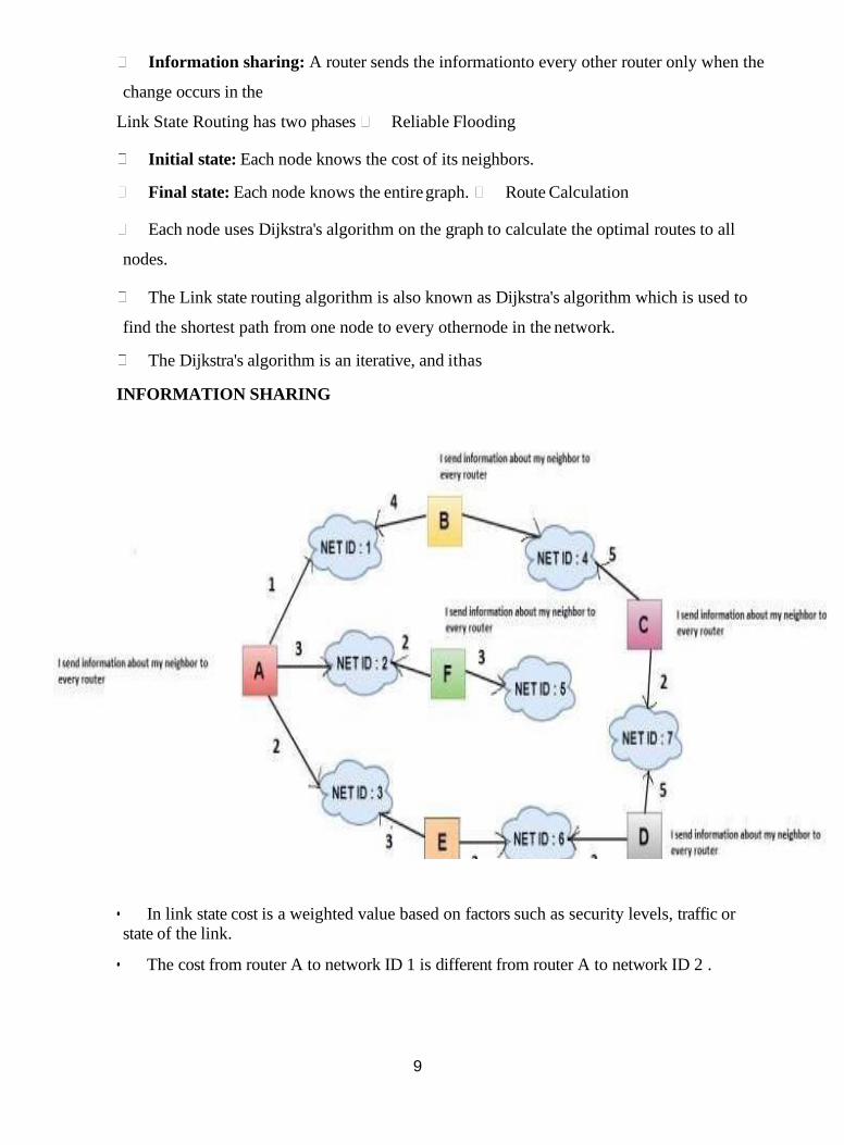
9
Information sharing: A router sends the informationto every other router only when the
change occurs in the
Link State Routing has two phases Reliable Flooding
Initial state: Each node knows the cost of its neighbors.
Final state: Each node knows the entire graph. Route Calculation
Each node uses Dijkstra's algorithm on the graph to calculate the optimal routes to all
nodes.
The Link state routing algorithm is also known as Dijkstra's algorithm which is used to
find the shortest path from one node to every othernode in the network.
The Dijkstra's algorithm is an iterative, and ithas
INFORMATION SHARING
• In link state cost is a weighted value based on factors such as security levels, traffic or state of the link.
• The cost from router A to network ID 1 is different from router A to network ID 2 .
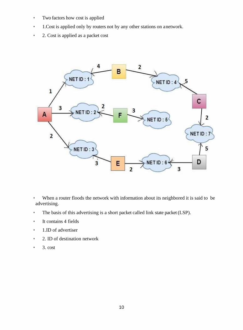
10
• Two factors how cost is applied
• 1.Cost is applied only by routers not by any other stations on a network.
• 2. Cost is applied as a packet cost
• When a router floods the network with information about its neighbored it is said to be advertising.
• The basis of this advertising is a short packet called link state packet (LSP).
• It contains 4 fields
• 1.ID of advertiser
• 2. ID of destination network
• 3. cost
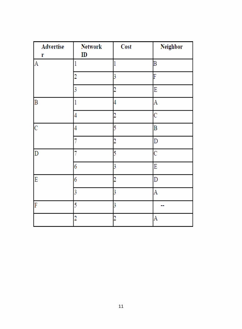
11
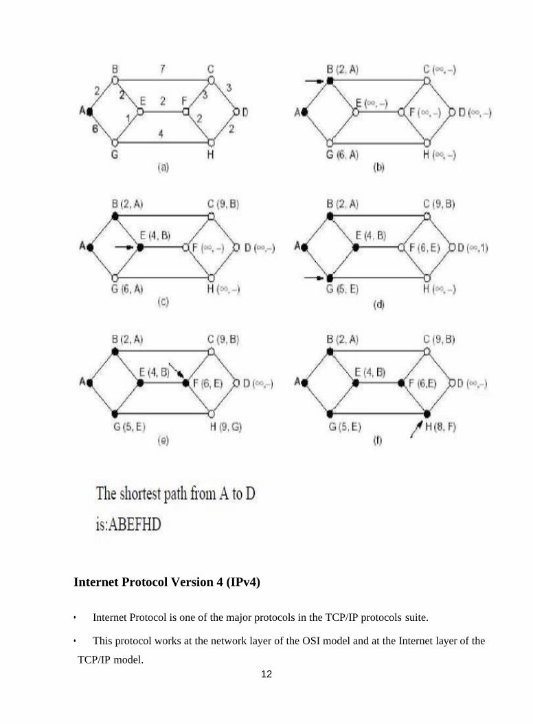
12
Internet Protocol Version 4 (IPv4)
• Internet Protocol is one of the major protocols in the TCP/IP protocols suite.
• This protocol works at the network layer of the OSI model and at the Internet layer of the
TCP/IP model.
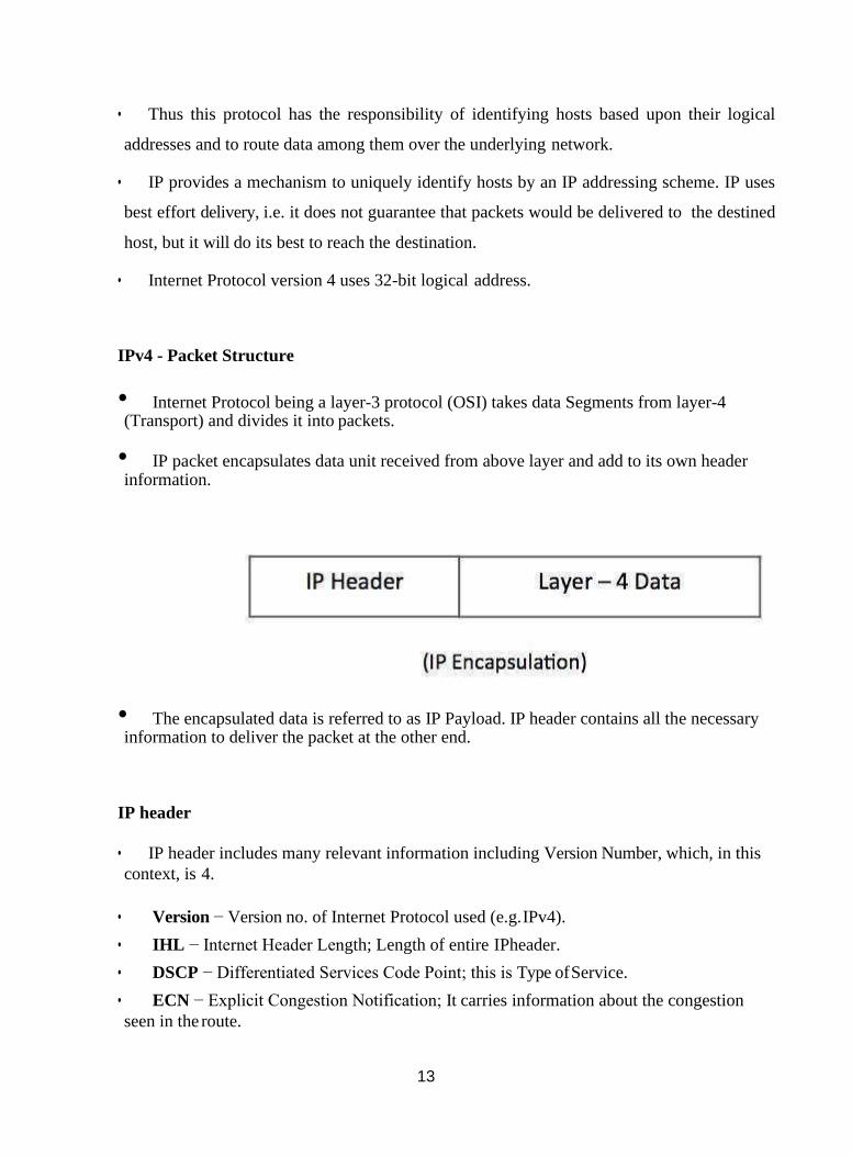
13
• Thus this protocol has the responsibility of identifying hosts based upon their logical
addresses and to route data among them over the underlying network.
• IP provides a mechanism to uniquely identify hosts by an IP addressing scheme. IP uses
best effort delivery, i.e. it does not guarantee that packets would be delivered to the destined
host, but it will do its best to reach the destination.
• Internet Protocol version 4 uses 32-bit logical address.
IPv4 - Packet Structure
• Internet Protocol being a layer-3 protocol (OSI) takes data Segments from layer-4 (Transport) and divides it into packets.
• IP packet encapsulates data unit received from above layer and add to its own header information.
• The encapsulated data is referred to as IP Payload. IP header contains all the necessary information to deliver the packet at the other end.
IP header
• IP header includes many relevant information including Version Number, which, in this
context, is 4.
• Version − Version no. of Internet Protocol used (e.g. IPv4).
• IHL − Internet Header Length; Length of entire IPheader.
• DSCP − Differentiated Services Code Point; this is Type of Service.
• ECN − Explicit Congestion Notification; It carries information about the congestion
seen in the route.
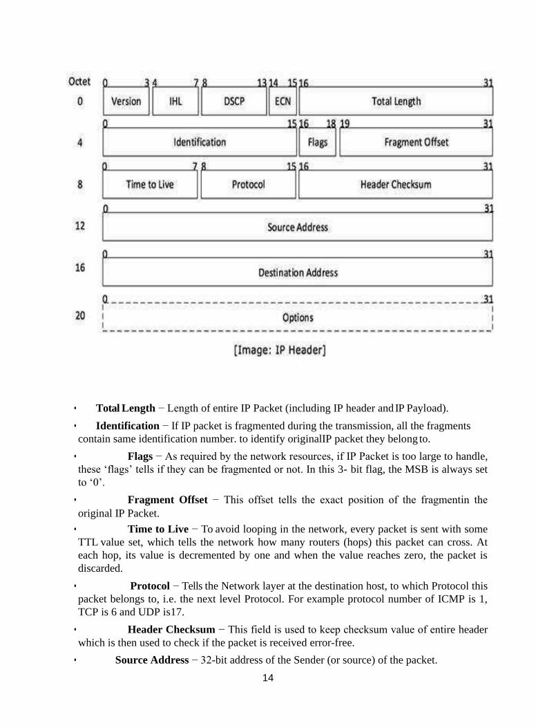
14
• Total Length − Length of entire IP Packet (including IP header and IP Payload).
• Identification − If IP packet is fragmented during the transmission, all the fragments
contain same identification number. to identify originalIP packet they belong to.
• Flags − As required by the network resources, if IP Packet is too large to handle,
these ‘flags’ tells if they can be fragmented or not. In this 3- bit flag, the MSB is always set
to ‘0’.
• Fragment Offset − This offset tells the exact position of the fragmentin the
original IP Packet.
• Time to Live − To avoid looping in the network, every packet is sent with some
TTL value set, which tells the network how many routers (hops) this packet can cross. At
each hop, its value is decremented by one and when the value reaches zero, the packet is
discarded.
• Protocol − Tells the Network layer at the destination host, to which Protocol this
packet belongs to, i.e. the next level Protocol. For example protocol number of ICMP is 1,
TCP is 6 and UDP is17.
• Header Checksum − This field is used to keep checksum value of entire header
which is then used to check if the packet is received error-free.
• Source Address − 32-bit address of the Sender (or source) of the packet.
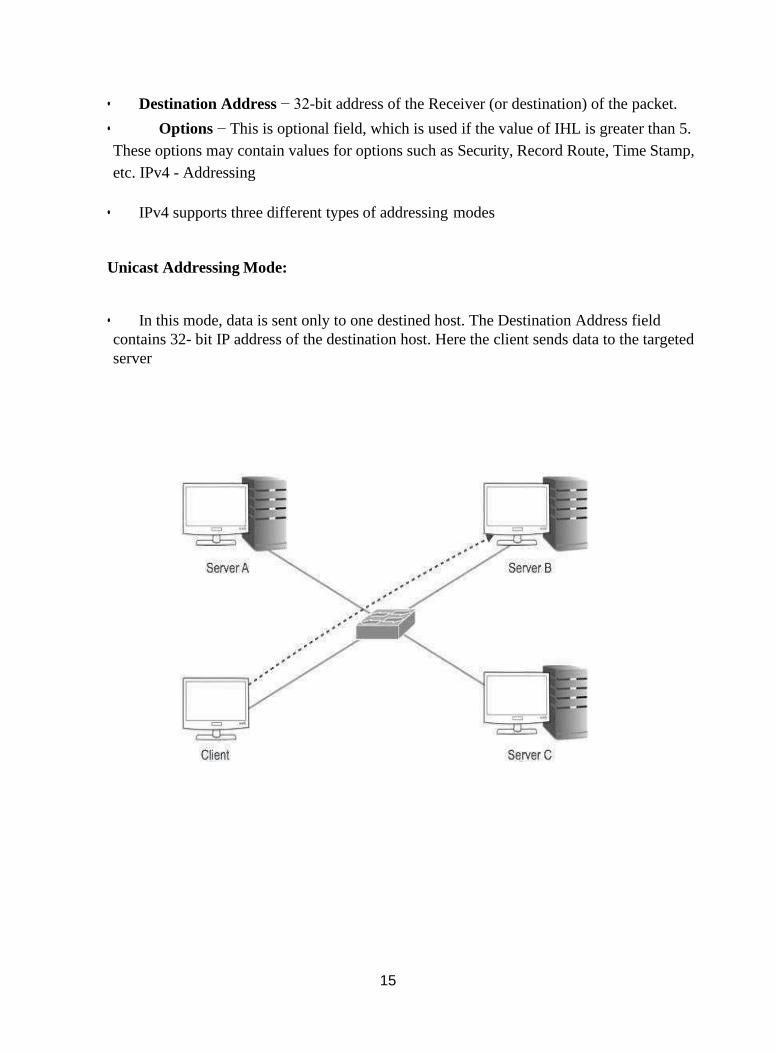
15
• Destination Address − 32-bit address of the Receiver (or destination) of the packet.
• Options − This is optional field, which is used if the value of IHL is greater than 5.
These options may contain values for options such as Security, Record Route, Time Stamp,
etc. IPv4 - Addressing
• IPv4 supports three different types of addressing modes
Unicast Addressing Mode:
• In this mode, data is sent only to one destined host. The Destination Address field
contains 32- bit IP address of the destination host. Here the client sends data to the targeted
server

16
Broadcast Addressing Mode:
• In this mode, the packet is addressed to all the hosts in a network segment. The
Destination Address field contains a special broadcast address, i.e. 255.255.255.255.
When a host sees this packet on the network, it is bound to process it. Here the client
sends a packet, which is entertained by all the Servers
• Multicast Addressing Mode :
• This mode is a mix of the previous two modes, i.e. the packet sent is neither
destined to a single host nor all the hosts on the segment. In this packet, the Destination
Address contains a special address which starts with 224.x.x.x and can be entertained by
more than one host.
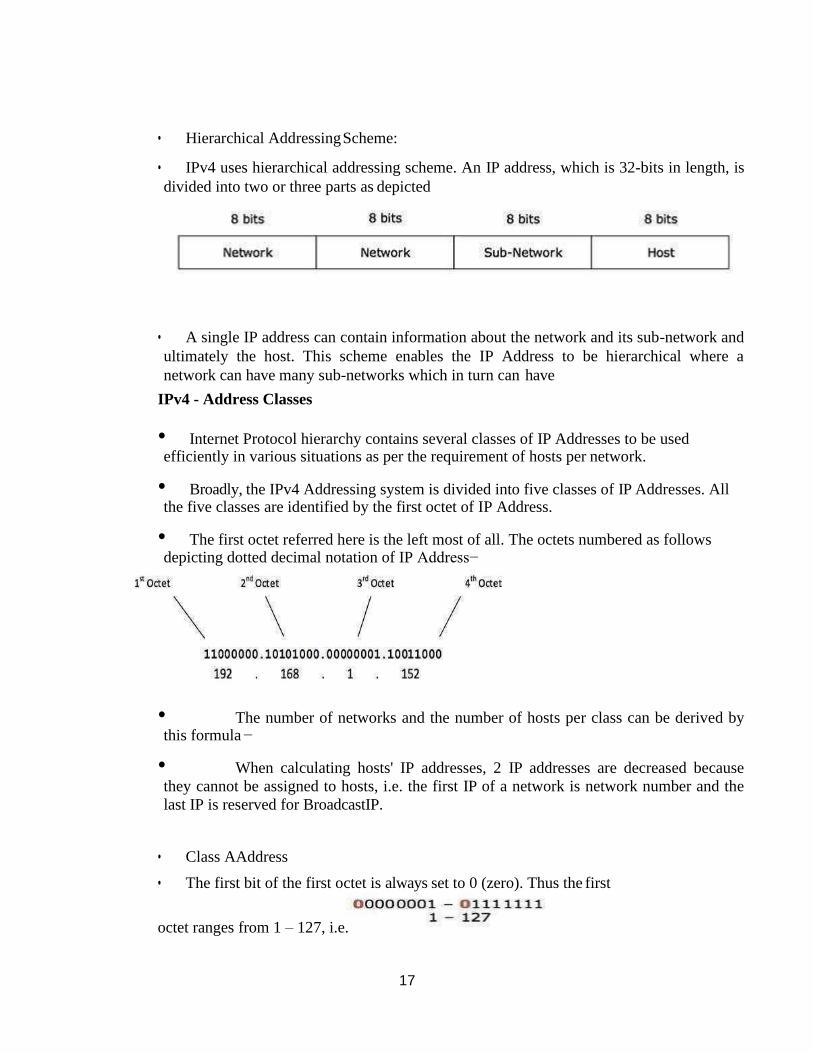
17
• Hierarchical Addressing Scheme:
• IPv4 uses hierarchical addressing scheme. An IP address, which is 32-bits in length, is
divided into two or three parts as depicted
• A single IP address can contain information about the network and its sub-network and
ultimately the host. This scheme enables the IP Address to be hierarchical where a
network can have many sub-networks which in turn can have
IPv4 - Address Classes
• Internet Protocol hierarchy contains several classes of IP Addresses to be used efficiently in various situations as per the requirement of hosts per network.
• Broadly, the IPv4 Addressing system is divided into five classes of IP Addresses. All the five classes are identified by the first octet of IP Address.
• The first octet referred here is the left most of all. The octets numbered as follows depicting dotted decimal notation of IP Address−
• The number of networks and the number of hosts per class can be derived by this formula −
• When calculating hosts' IP addresses, 2 IP addresses are decreased because
they cannot be assigned to hosts, i.e. the first IP of a network is network number and the
last IP is reserved for BroadcastIP.
• Class AAddress
• The first bit of the first octet is always set to 0 (zero). Thus the first
octet ranges from 1 – 127, i.e.
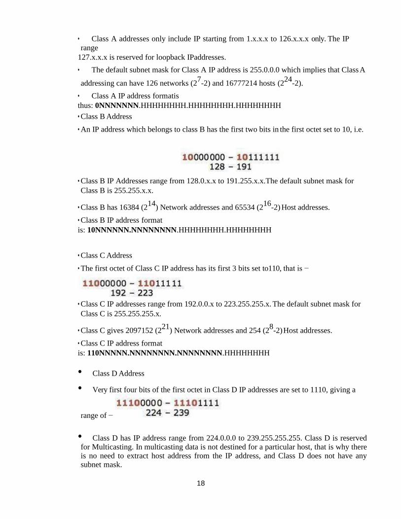
18
• Class A addresses only include IP starting from 1.x.x.x to 126.x.x.x only. The IP
range
127.x.x.x is reserved for loopback IPaddresses.
• The default subnet mask for Class A IP address is 255.0.0.0 which implies that Class A
addressing can have 126 networks (27-2) and 16777214 hosts (2
24-2).
• Class A IP address formatis
thus: 0NNNNNNN.HHHHHHHH.HHHHHHHH.HHHHHHHH
• Class B Address
• An IP address which belongs to class B has the first two bits in the first octet set to 10, i.e.
• Class B IP Addresses range from 128.0.x.x to 191.255.x.x.The default subnet mask for
Class B is 255.255.x.x.
• Class B has 16384 (214
) Network addresses and 65534 (216
-2) Host addresses.
• Class B IP address format
is: 10NNNNNN.NNNNNNNN.HHHHHHHH.HHHHHHHH
• Class C Address
• The first octet of Class C IP address has its first 3 bits set to110, that is −
• Class C IP addresses range from 192.0.0.x to 223.255.255.x. The default subnet mask for
Class C is 255.255.255.x.
• Class C gives 2097152 (221
) Network addresses and 254 (28-2) Host addresses.
• Class C IP address format
is: 110NNNNN.NNNNNNNN.NNNNNNNN.HHHHHHHH
• Class D Address
• Very first four bits of the first octet in Class D IP addresses are set to 1110, giving a
range of −
• Class D has IP address range from 224.0.0.0 to 239.255.255.255. Class D is reserved for Multicasting. In multicasting data is not destined for a particular host, that is why there is no need to extract host address from the IP address, and Class D does not have any subnet mask.
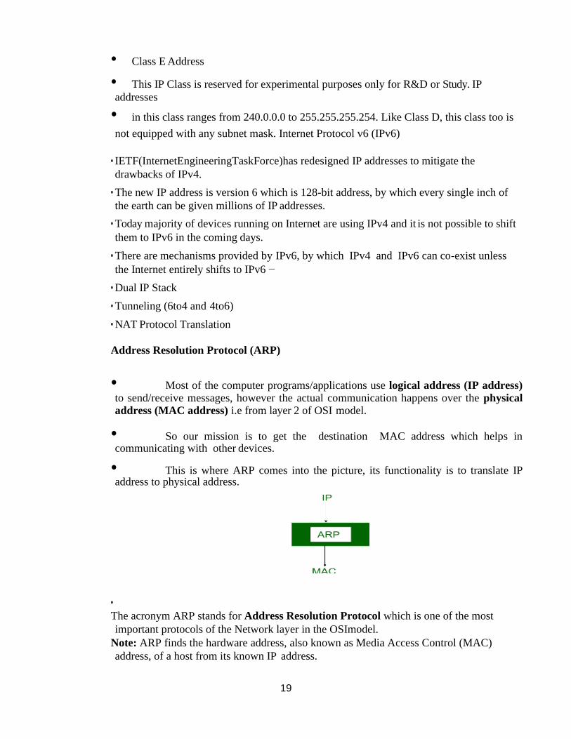
19
• Class E Address
• This IP Class is reserved for experimental purposes only for R&D or Study. IP
addresses
• in this class ranges from 240.0.0.0 to 255.255.255.254. Like Class D, this class too is
not equipped with any subnet mask. Internet Protocol v6 (IPv6)
• IETF(InternetEngineeringTaskForce)has redesigned IP addresses to mitigate the
drawbacks of IPv4.
• The new IP address is version 6 which is 128-bit address, by which every single inch of
the earth can be given millions of IP addresses.
• Today majority of devices running on Internet are using IPv4 and it is not possible to shift
them to IPv6 in the coming days.
• There are mechanisms provided by IPv6, by which IPv4 and IPv6 can co-exist unless
the Internet entirely shifts to IPv6 −
• Dual IP Stack
• Tunneling (6to4 and 4to6)
• NAT Protocol Translation
Address Resolution Protocol (ARP)
• Most of the computer programs/applications use logical address (IP address)
to send/receive messages, however the actual communication happens over the physical
address (MAC address) i.e from layer 2 of OSI model.
• So our mission is to get the destination MAC address which helps in communicating with other devices.
• This is where ARP comes into the picture, its functionality is to translate IP address to physical address.
•
The acronym ARP stands for Address Resolution Protocol which is one of the most
important protocols of the Network layer in the OSImodel.
Note: ARP finds the hardware address, also known as Media Access Control (MAC)
address, of a host from its known IP address.
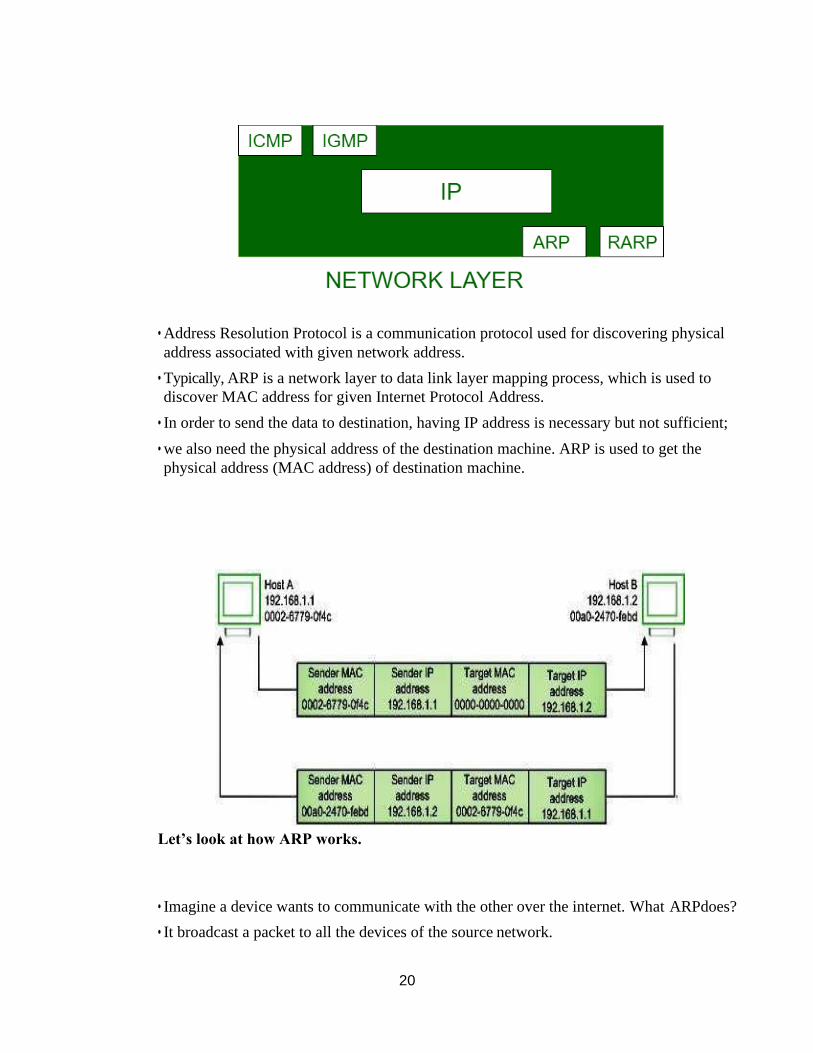
20
• Address Resolution Protocol is a communication protocol used for discovering physical
address associated with given network address.
• Typically, ARP is a network layer to data link layer mapping process, which is used to
discover MAC address for given Internet Protocol Address.
• In order to send the data to destination, having IP address is necessary but not sufficient;
• we also need the physical address of the destination machine. ARP is used to get the
physical address (MAC address) of destination machine.
Let’s look at how ARP works.
• Imagine a device wants to communicate with the other over the internet. What ARPdoes?
• It broadcast a packet to all the devices of the source network.
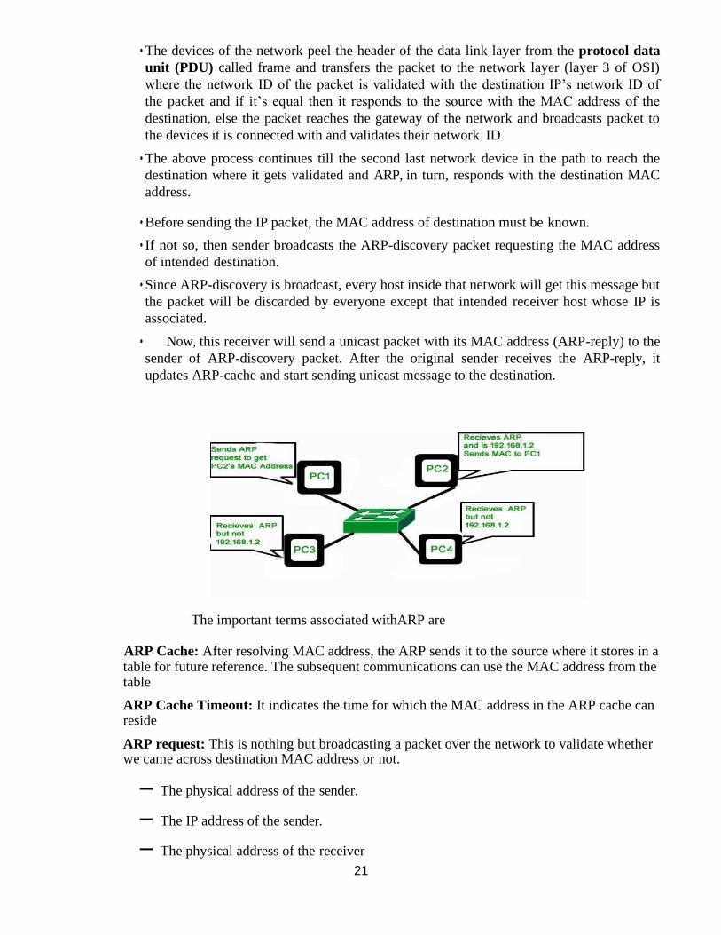
21
• The devices of the network peel the header of the data link layer from the protocol data
unit (PDU) called frame and transfers the packet to the network layer (layer 3 of OSI)
where the network ID of the packet is validated with the destination IP’s network ID of
the packet and if it’s equal then it responds to the source with the MAC address of the
destination, else the packet reaches the gateway of the network and broadcasts packet to
the devices it is connected with and validates their network ID
• The above process continues till the second last network device in the path to reach the
destination where it gets validated and ARP, in turn, responds with the destination MAC
address.
• Before sending the IP packet, the MAC address of destination must be known.
• If not so, then sender broadcasts the ARP-discovery packet requesting the MAC address
of intended destination.
• Since ARP-discovery is broadcast, every host inside that network will get this message but
the packet will be discarded by everyone except that intended receiver host whose IP is
associated.
• Now, this receiver will send a unicast packet with its MAC address (ARP-reply) to the
sender of ARP-discovery packet. After the original sender receives the ARP-reply, it
updates ARP-cache and start sending unicast message to the destination.
The important terms associated withARP are
ARP Cache: After resolving MAC address, the ARP sends it to the source where it stores in a table for future reference. The subsequent communications can use the MAC address from the table
ARP Cache Timeout: It indicates the time for which the MAC address in the ARP cache can reside
ARP request: This is nothing but broadcasting a packet over the network to validate whether we came across destination MAC address or not.
– The physical address of the sender.
– The IP address of the sender.
– The physical address of the receiver
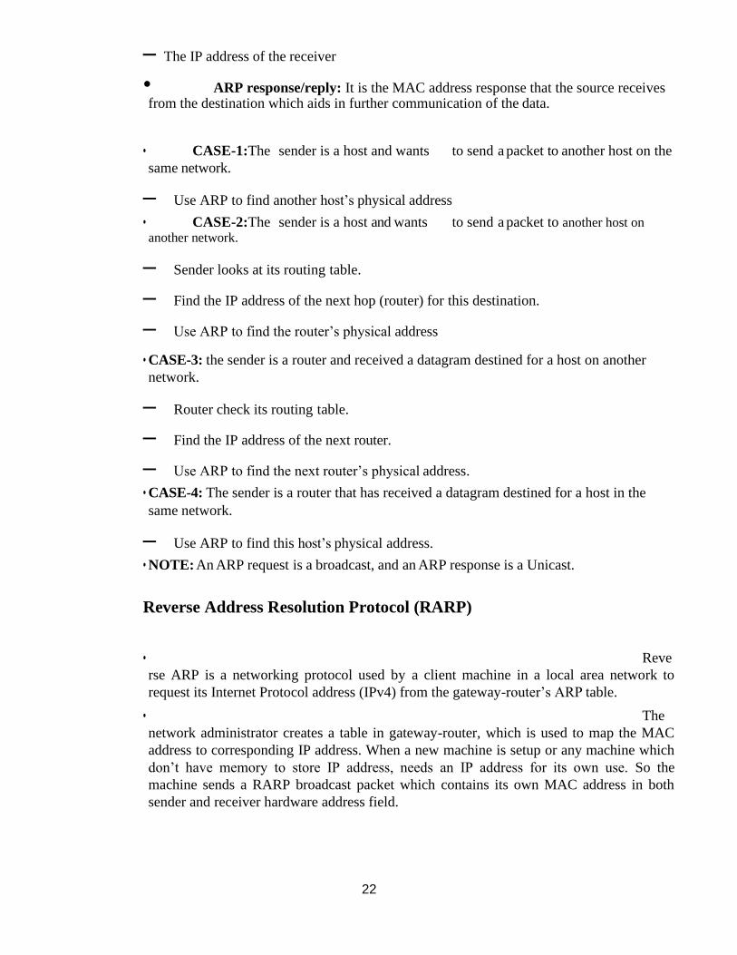
22
– The IP address of the receiver
• ARP response/reply: It is the MAC address response that the source receives from the destination which aids in further communication of the data.
• CASE-1:The sender is a host and wants to send a packet to another host on the
same network.
– Use ARP to find another host’s physical address
• CASE-2:The sender is a host and wants to send a packet to another host on
another network.
– Sender looks at its routing table.
– Find the IP address of the next hop (router) for this destination.
– Use ARP to find the router’s physical address
• CASE-3: the sender is a router and received a datagram destined for a host on another
network.
– Router check its routing table.
– Find the IP address of the next router.
– Use ARP to find the next router’s physical address.
• CASE-4: The sender is a router that has received a datagram destined for a host in the
same network.
– Use ARP to find this host’s physical address.
• NOTE: An ARP request is a broadcast, and an ARP response is a Unicast.
Reverse Address Resolution Protocol (RARP)
• Reve
rse ARP is a networking protocol used by a client machine in a local area network to
request its Internet Protocol address (IPv4) from the gateway-router’s ARP table.
• The
network administrator creates a table in gateway-router, which is used to map the MAC
address to corresponding IP address. When a new machine is setup or any machine which
don’t have memory to store IP address, needs an IP address for its own use. So the
machine sends a RARP broadcast packet which contains its own MAC address in both
sender and receiver hardware address field.
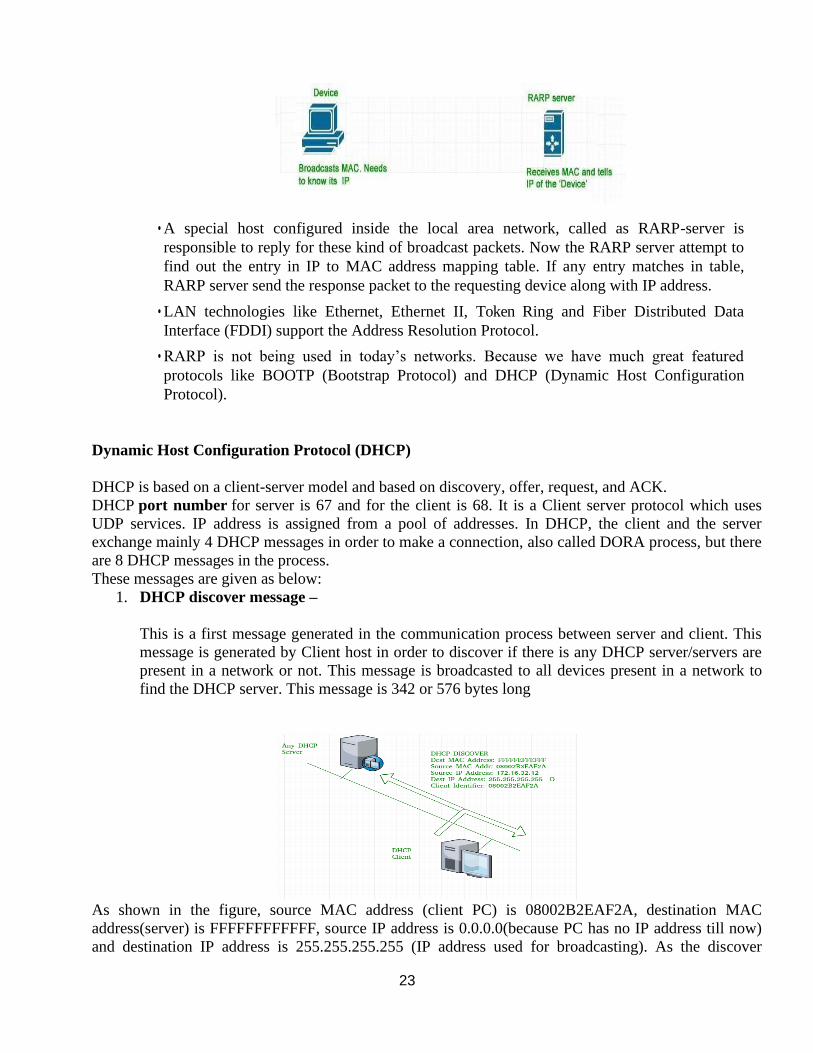
23
• A special host configured inside the local area network, called as RARP-server is
responsible to reply for these kind of broadcast packets. Now the RARP server attempt to
find out the entry in IP to MAC address mapping table. If any entry matches in table,
RARP server send the response packet to the requesting device along with IP address.
• LAN technologies like Ethernet, Ethernet II, Token Ring and Fiber Distributed Data
Interface (FDDI) support the Address Resolution Protocol.
• RARP is not being used in today’s networks. Because we have much great featured
protocols like BOOTP (Bootstrap Protocol) and DHCP (Dynamic Host Configuration
Protocol).
Dynamic Host Configuration Protocol (DHCP)
DHCP is based on a client-server model and based on discovery, offer, request, and ACK.
DHCP port number for server is 67 and for the client is 68. It is a Client server protocol which uses
UDP services. IP address is assigned from a pool of addresses. In DHCP, the client and the server
exchange mainly 4 DHCP messages in order to make a connection, also called DORA process, but there
are 8 DHCP messages in the process.
These messages are given as below:
1. DHCP discover message –
This is a first message generated in the communication process between server and client. This
message is generated by Client host in order to discover if there is any DHCP server/servers are
present in a network or not. This message is broadcasted to all devices present in a network to
find the DHCP server. This message is 342 or 576 bytes long
As shown in the figure, source MAC address (client PC) is 08002B2EAF2A, destination MAC
address(server) is FFFFFFFFFFFF, source IP address is 0.0.0.0(because PC has no IP address till now)
and destination IP address is 255.255.255.255 (IP address used for broadcasting). As the discover
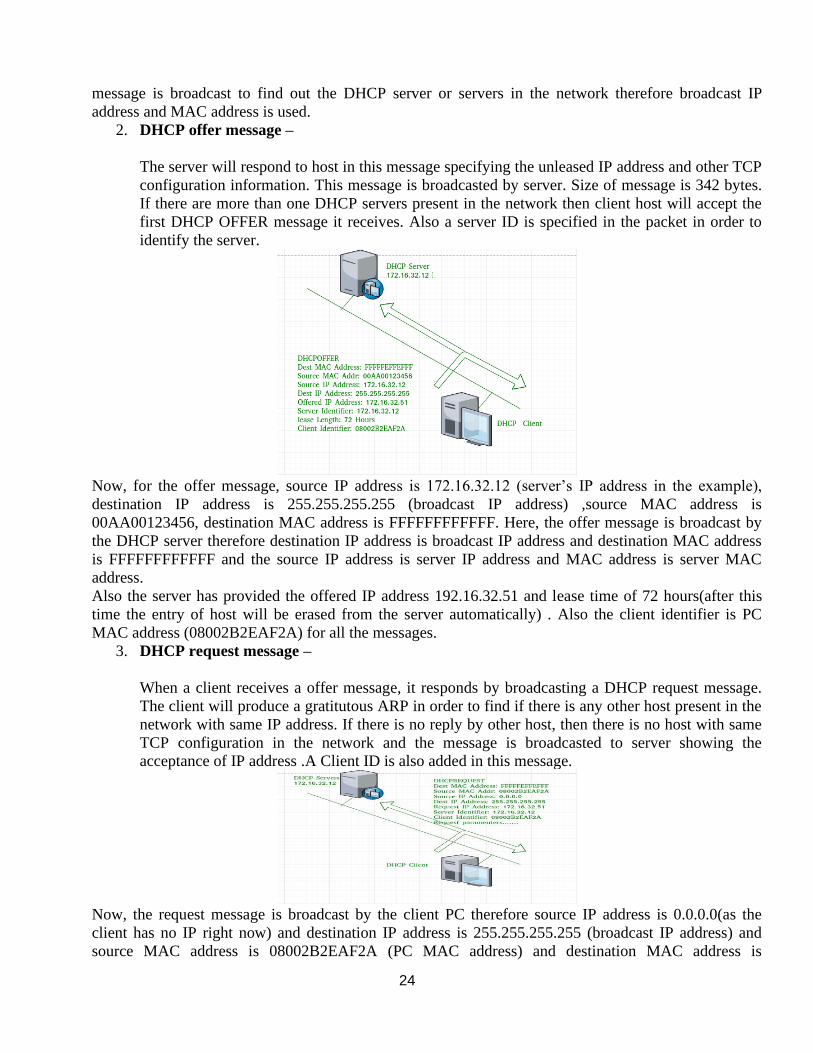
24
message is broadcast to find out the DHCP server or servers in the network therefore broadcast IP
address and MAC address is used.
2. DHCP offer message –
The server will respond to host in this message specifying the unleased IP address and other TCP
configuration information. This message is broadcasted by server. Size of message is 342 bytes.
If there are more than one DHCP servers present in the network then client host will accept the
first DHCP OFFER message it receives. Also a server ID is specified in the packet in order to
identify the server.
Now, for the offer message, source IP address is 172.16.32.12 (server’s IP address in the example),
destination IP address is 255.255.255.255 (broadcast IP address) ,source MAC address is
00AA00123456, destination MAC address is FFFFFFFFFFFF. Here, the offer message is broadcast by
the DHCP server therefore destination IP address is broadcast IP address and destination MAC address
is FFFFFFFFFFFF and the source IP address is server IP address and MAC address is server MAC
address.
Also the server has provided the offered IP address 192.16.32.51 and lease time of 72 hours(after this
time the entry of host will be erased from the server automatically) . Also the client identifier is PC
MAC address (08002B2EAF2A) for all the messages.
3. DHCP request message –
When a client receives a offer message, it responds by broadcasting a DHCP request message.
The client will produce a gratitutous ARP in order to find if there is any other host present in the
network with same IP address. If there is no reply by other host, then there is no host with same
TCP configuration in the network and the message is broadcasted to server showing the
acceptance of IP address .A Client ID is also added in this message.
Now, the request message is broadcast by the client PC therefore source IP address is 0.0.0.0(as the
client has no IP right now) and destination IP address is 255.255.255.255 (broadcast IP address) and
source MAC address is 08002B2EAF2A (PC MAC address) and destination MAC address is
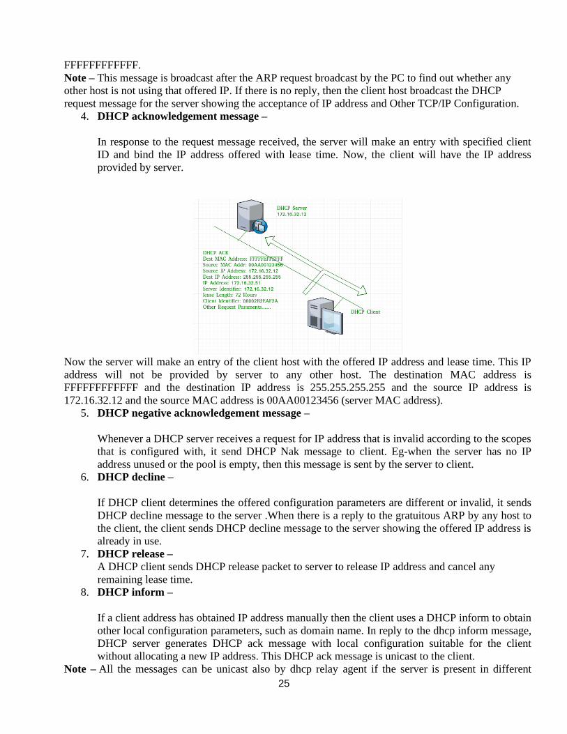
25
FFFFFFFFFFFF.
Note – This message is broadcast after the ARP request broadcast by the PC to find out whether any
other host is not using that offered IP. If there is no reply, then the client host broadcast the DHCP
request message for the server showing the acceptance of IP address and Other TCP/IP Configuration.
4. DHCP acknowledgement message –
In response to the request message received, the server will make an entry with specified client
ID and bind the IP address offered with lease time. Now, the client will have the IP address
provided by server.
Now the server will make an entry of the client host with the offered IP address and lease time. This IP
address will not be provided by server to any other host. The destination MAC address is
FFFFFFFFFFFF and the destination IP address is 255.255.255.255 and the source IP address is
172.16.32.12 and the source MAC address is 00AA00123456 (server MAC address).
5. DHCP negative acknowledgement message –
Whenever a DHCP server receives a request for IP address that is invalid according to the scopes
that is configured with, it send DHCP Nak message to client. Eg-when the server has no IP
address unused or the pool is empty, then this message is sent by the server to client.
6. DHCP decline –
If DHCP client determines the offered configuration parameters are different or invalid, it sends
DHCP decline message to the server .When there is a reply to the gratuitous ARP by any host to
the client, the client sends DHCP decline message to the server showing the offered IP address is
already in use.
7. DHCP release –
A DHCP client sends DHCP release packet to server to release IP address and cancel any
remaining lease time.
8. DHCP inform –
If a client address has obtained IP address manually then the client uses a DHCP inform to obtain
other local configuration parameters, such as domain name. In reply to the dhcp inform message,
DHCP server generates DHCP ack message with local configuration suitable for the client
without allocating a new IP address. This DHCP ack message is unicast to the client.
Note – All the messages can be unicast also by dhcp relay agent if the server is present in different
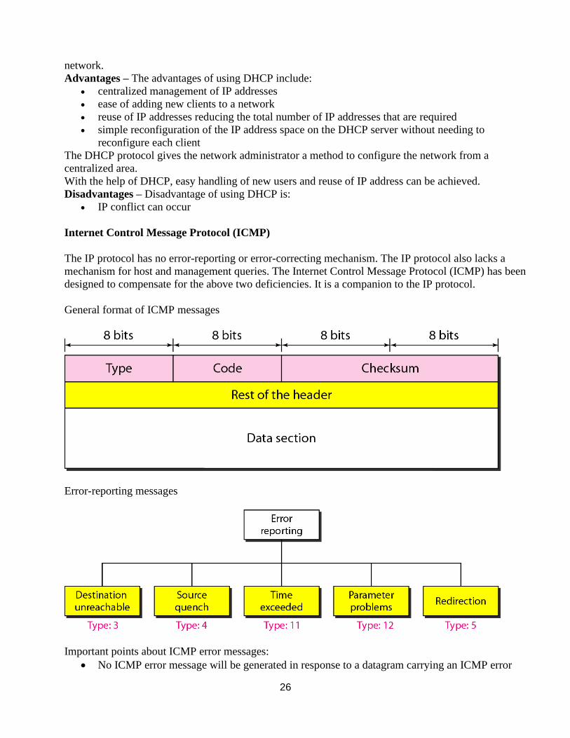
26
network.
Advantages – The advantages of using DHCP include:
• centralized management of IP addresses
• ease of adding new clients to a network
• reuse of IP addresses reducing the total number of IP addresses that are required
• simple reconfiguration of the IP address space on the DHCP server without needing to
reconfigure each client
The DHCP protocol gives the network administrator a method to configure the network from a
centralized area.
With the help of DHCP, easy handling of new users and reuse of IP address can be achieved.
Disadvantages – Disadvantage of using DHCP is:
• IP conflict can occur
Internet Control Message Protocol (ICMP)
The IP protocol has no error-reporting or error-correcting mechanism. The IP protocol also lacks a
mechanism for host and management queries. The Internet Control Message Protocol (ICMP) has been
designed to compensate for the above two deficiencies. It is a companion to the IP protocol.
General format of ICMP messages
Error-reporting messages
Important points about ICMP error messages:
• No ICMP error message will be generated in response to a datagram carrying an ICMP error
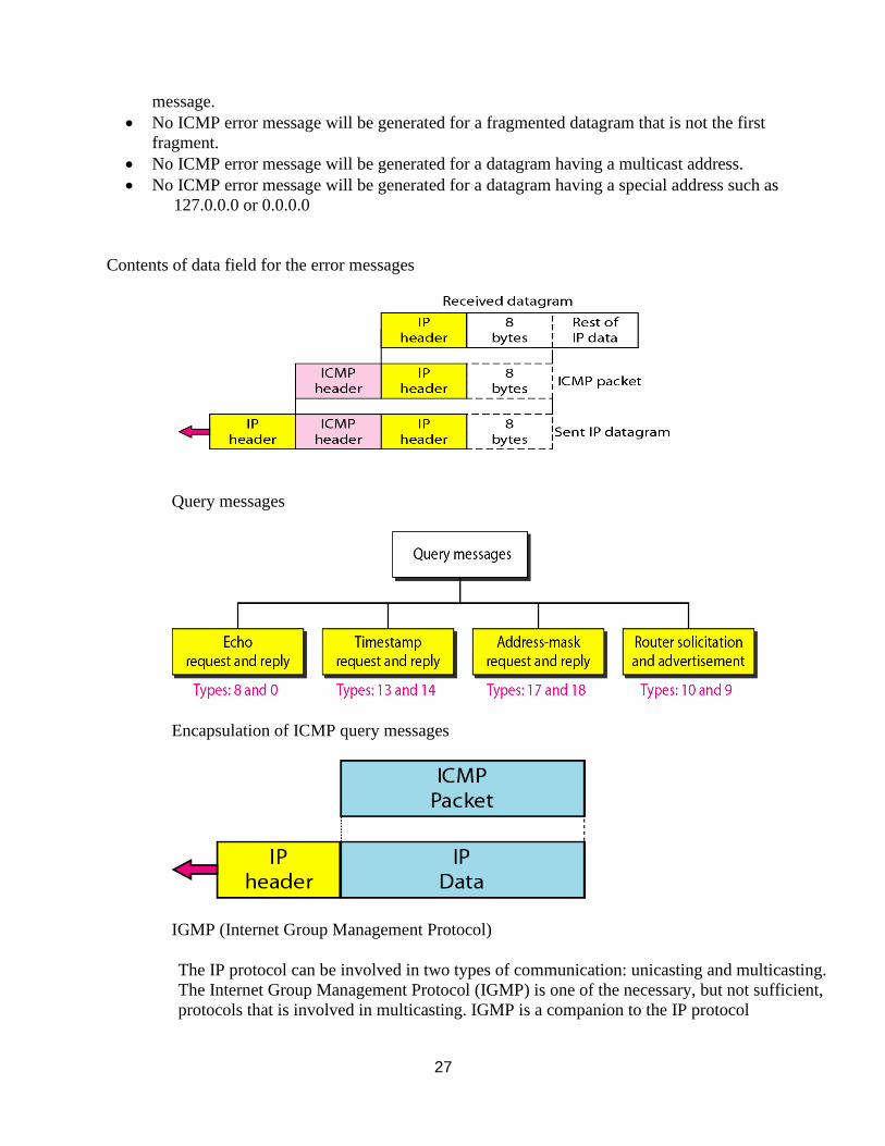
27
message.
• No ICMP error message will be generated for a fragmented datagram that is not the first
fragment.
• No ICMP error message will be generated for a datagram having a multicast address.
• No ICMP error message will be generated for a datagram having a special address such as
127.0.0.0 or 0.0.0.0
Contents of data field for the error messages
Query messages
Encapsulation of ICMP query messages
IGMP (Internet Group Management Protocol)
The IP protocol can be involved in two types of communication: unicasting and multicasting.
The Internet Group Management Protocol (IGMP) is one of the necessary, but not sufficient,
protocols that is involved in multicasting. IGMP is a companion to the IP protocol
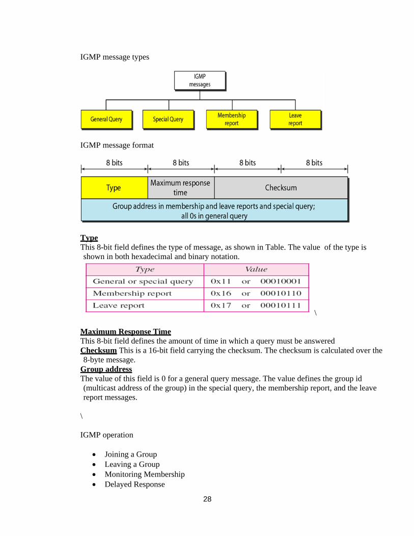
28
IGMP message types
IGMP message format
Type
This 8-bit field defines the type of message, as shown in Table. The value of the type is
shown in both hexadecimal and binary notation.
\
Maximum Response Time
This 8-bit field defines the amount of time in which a query must be answered
Checksum This is a 16-bit field carrying the checksum. The checksum is calculated over the
8-byte message.
Group address
The value of this field is 0 for a general query message. The value defines the group id
(multicast address of the group) in the special query, the membership report, and the leave
report messages.
\
IGMP operation
• Joining a Group
• Leaving a Group
• Monitoring Membership
• Delayed Response
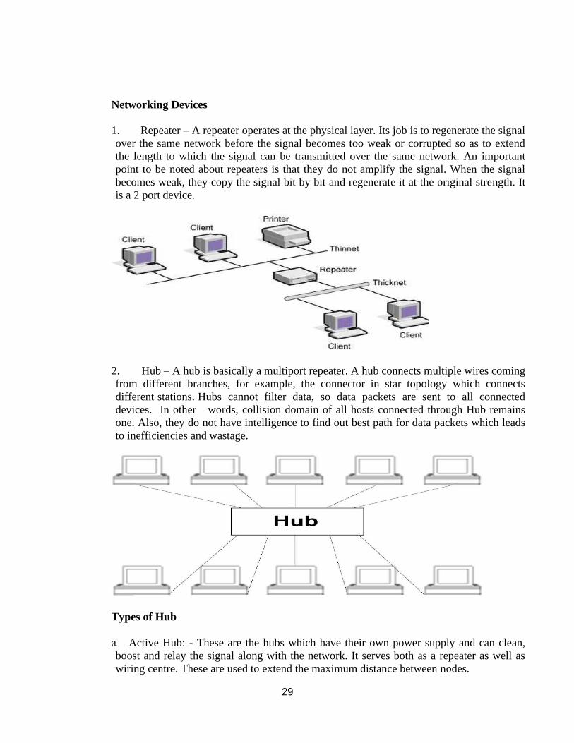
29
Networking Devices
1. Repeater – A repeater operates at the physical layer. Its job is to regenerate the signal
over the same network before the signal becomes too weak or corrupted so as to extend
the length to which the signal can be transmitted over the same network. An important
point to be noted about repeaters is that they do not amplify the signal. When the signal
becomes weak, they copy the signal bit by bit and regenerate it at the original strength. It
is a 2 port device.
2. Hub – A hub is basically a multiport repeater. A hub connects multiple wires coming
from different branches, for example, the connector in star topology which connects
different stations. Hubs cannot filter data, so data packets are sent to all connected
devices. In other words, collision domain of all hosts connected through Hub remains
one. Also, they do not have intelligence to find out best path for data packets which leads
to inefficiencies and wastage.
Types of Hub
a. Active Hub: - These are the hubs which have their own power supply and can clean,
boost and relay the signal along with the network. It serves both as a repeater as well as
wiring centre. These are used to extend the maximum distance between nodes.
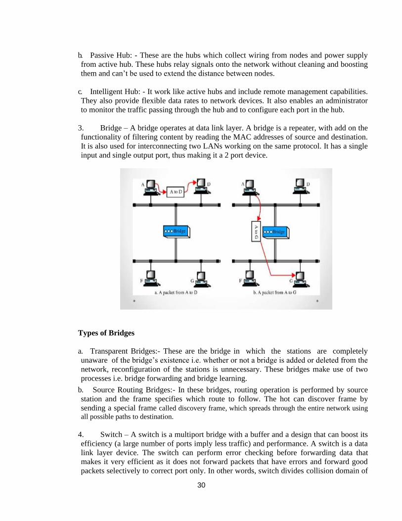
30
b. Passive Hub: - These are the hubs which collect wiring from nodes and power supply
from active hub. These hubs relay signals onto the network without cleaning and boosting
them and can’t be used to extend the distance between nodes.
c. Intelligent Hub: - It work like active hubs and include remote management capabilities.
They also provide flexible data rates to network devices. It also enables an administrator
to monitor the traffic passing through the hub and to configure each port in the hub.
3. Bridge – A bridge operates at data link layer. A bridge is a repeater, with add on the
functionality of filtering content by reading the MAC addresses of source and destination.
It is also used for interconnecting two LANs working on the same protocol. It has a single
input and single output port, thus making it a 2 port device.
Types of Bridges
a. Transparent Bridges:- These are the bridge in which the stations are completely
unaware of the bridge’s existence i.e. whether or not a bridge is added or deleted from the
network, reconfiguration of the stations is unnecessary. These bridges make use of two
processes i.e. bridge forwarding and bridge learning.
b. Source Routing Bridges:- In these bridges, routing operation is performed by source
station and the frame specifies which route to follow. The hot can discover frame by
sending a special frame called discovery frame, which spreads through the entire network using
all possible paths to destination.
4. Switch – A switch is a multiport bridge with a buffer and a design that can boost its
efficiency (a large number of ports imply less traffic) and performance. A switch is a data
link layer device. The switch can perform error checking before forwarding data that
makes it very efficient as it does not forward packets that have errors and forward good
packets selectively to correct port only. In other words, switch divides collision domain of
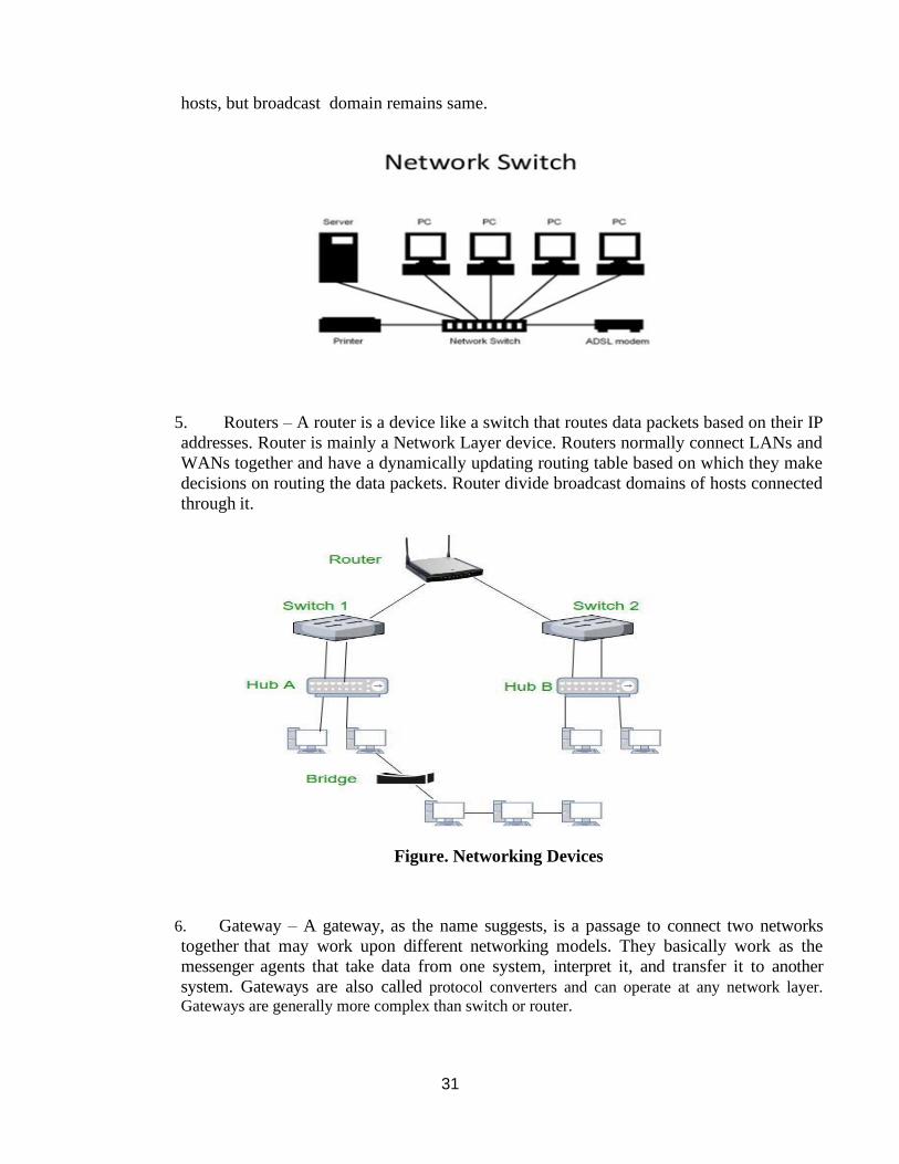
31
hosts, but broadcast domain remains same.
5. Routers – A router is a device like a switch that routes data packets based on their IP
addresses. Router is mainly a Network Layer device. Routers normally connect LANs and
WANs together and have a dynamically updating routing table based on which they make
decisions on routing the data packets. Router divide broadcast domains of hosts connected
through it.
Figure. Networking Devices
6. Gateway – A gateway, as the name suggests, is a passage to connect two networks
together that may work upon different networking models. They basically work as the
messenger agents that take data from one system, interpret it, and transfer it to another
system. Gateways are also called protocol converters and can operate at any network layer.
Gateways are generally more complex than switch or router.
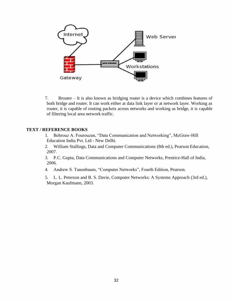
32
7. Brouter – It is also known as bridging router is a device which combines features of
both bridge and router. It can work either at data link layer or at network layer. Working as
router, it is capable of routing packets across networks and working as bridge, it is capable
of filtering local area network traffic.
TEXT / REFERENCE BOOKS
1. Behrouz A. Fourouzan, “Data Communication and Networking”, McGraw-Hill
Education India Pvt. Ltd - New Delhi.
2. William Stallings, Data and Computer Communications (8th ed.), Pearson Education,
2007.
3. P.C. Gupta, Data Communications and Computer Networks, Prentice-Hall of India,
2006.
4. Andrew S. Tanenbaum, “Computer Networks”, Fourth Edition, Pearson.
5. L. L. Peterson and B. S. Davie, Computer Networks: A Systems Approach (3rd ed.),
Morgan Kaufmann, 2003.
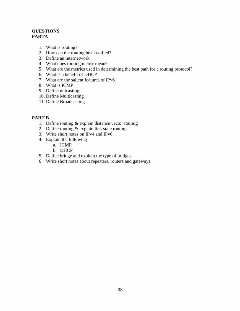
33
QUESTIONS
PARTA
1. What is routing?
2. How can the routing be classified?
3. Define an internetwork
4. What does routing metric mean?
5. What are the metrics used in determining the best path for a routing protocol?
6. What is a benefit of DHCP
7. What are the salient features of IPv6
8. What is ICMP
9. Define unicasting
10. Define Multicasting
11. Define Broadcasting
PART B
1. Define routing & explain distance vector routing
2. Define routing & explain link state routing.
3. Write short notes on IPv4 and IPv6
4. Explain the following
a. ICMP
b. DHCP
5. Define bridge and explain the type of bridges
6. Write short notes about repeaters, routers and gateways.
34
UNIT – IV – Data communication and Computer networks – SITA1401
SCHOOL OF COMPUTING
DEPARTMENT OF INFORMATION TECHNOLOGY
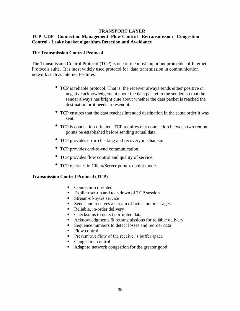
35
TRANSPORT LAYER
TCP- UDP - Connection Management- Flow Control - Retransmission - Congestion
Control - Leaky bucket algorithm-Detection and Avoidance
The Transmission Control Protocol
The Transmission Control Protocol (TCP) is one of the most important protocols of Internet
Protocols suite. It is most widely used protocol for data transmission in communication
network such as internet Features
• TCP is reliable protocol. That is, the receiver always sends either positive or
negative acknowledgement about the data packet to the sender, so that the
sender always has bright clue about whether the data packet is reached the
destination or it needs to resend it.
• TCP ensures that the data reaches intended destination in the same order it was
sent.
• TCP is connection oriented. TCP requires that connection between two remote
points be established before sending actual data.
• TCP provides error-checking and recovery mechanism.
• TCP provides end-to-end communication.
• TCP provides flow control and quality of service.
• TCP operates in Client/Server point-to-point mode.
Transmission Control Protocol (TCP)
▪ Connection oriented
▪ Explicit set-up and tear-down of TCP session
▪ Stream-of-bytes service
▪ Sends and receives a stream of bytes, not messages
▪ Reliable, in-order delivery
▪ Checksums to detect corrupted data
▪ Acknowledgments & retransmissions for reliable delivery
▪ Sequence numbers to detect losses and reorder data
▪ Flow control
▪ Prevent overflow of the receiver’s buffer space
▪ Congestion control
▪ Adapt to network congestion for the greater good
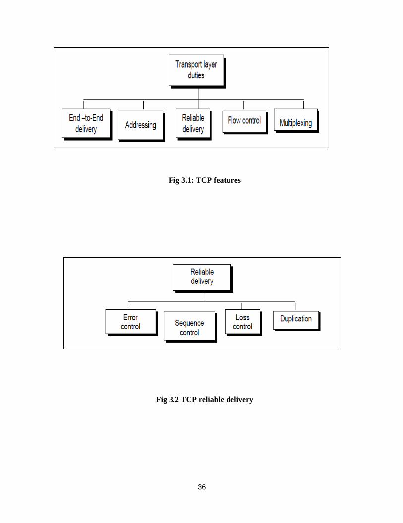
36
Fig 3.1: TCP features
Fig 3.2 TCP reliable delivery
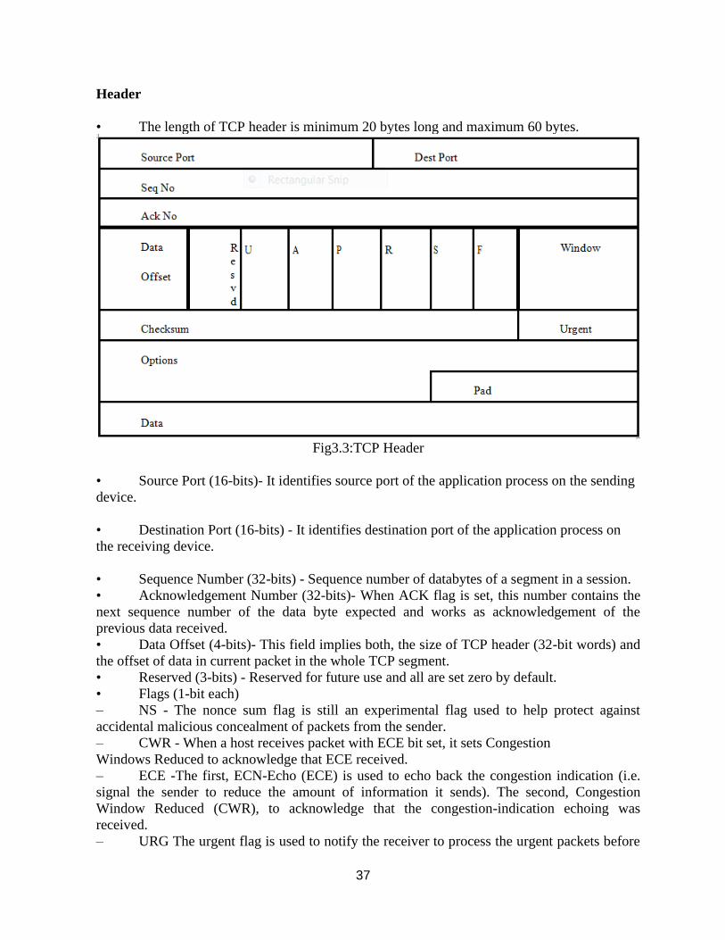
37
Header
• The length of TCP header is minimum 20 bytes long and maximum 60 bytes.
Fig3.3:TCP Header
• Source Port (16-bits)- It identifies source port of the application process on the sending
device.
• Destination Port (16-bits) - It identifies destination port of the application process on
the receiving device.
• Sequence Number (32-bits) - Sequence number of databytes of a segment in a session.
• Acknowledgement Number (32-bits)- When ACK flag is set, this number contains the
next sequence number of the data byte expected and works as acknowledgement of the
previous data received.
• Data Offset (4-bits)- This field implies both, the size of TCP header (32-bit words) and
the offset of data in current packet in the whole TCP segment.
• Reserved (3-bits) - Reserved for future use and all are set zero by default.
• Flags (1-bit each)
– NS - The nonce sum flag is still an experimental flag used to help protect against
accidental malicious concealment of packets from the sender.
– CWR - When a host receives packet with ECE bit set, it sets Congestion
Windows Reduced to acknowledge that ECE received.
– ECE -The first, ECN-Echo (ECE) is used to echo back the congestion indication (i.e.
signal the sender to reduce the amount of information it sends). The second, Congestion
Window Reduced (CWR), to acknowledge that the congestion-indication echoing was
received.
– URG The urgent flag is used to notify the receiver to process the urgent packets before
38
processing all other packets. The receiver will be notified when all known urgent data has been
received
– ACK - The acknowledgment flag is used to acknowledge the successful receipt
of a packet. As we can see from the diagram above, the receiver sends an
ACK as well as a SYN in the second step of the three way handshake process
to tell the sender that it received its initial packet..
– PSH - The push flag is somewhat similar to the URG flag When set, it is a
request to the receiving station to PUSH data (as soon as it comes) to the
receiving application without buffering it.
• RST - Reset flag has the following features:
– It is used to refuse an incoming connection.
– It is used to reject a segment.
– It is used to restart a connection.
• SYN - The synchronization flag is used as a first step in establishing a three
way handshake between two hosts. Only the first packet from both the sender
and receiver should have this flag set.
• FIN - The finished flag means there is no more data from the sender. Therefore,
it is used in the last packet sent from the sender
• Windows Size - This field is used for flow control between two stations and
indicates the amount of buffer (in bytes) the receiver has allocated for a
segment, i.e. how much data is the receiverexpecting.
• Checksum - This field contains the checksum of Header, Data and Pseudo
Headers.
• Urgent Pointer - It points to the urgent data byte if URG flag is set to 1.
• Options - It facilitates additional options which are not covered by the regular
header. Option field is always described in 32-bit words. If this field contains
data less than 32-bit, padding is used to cover the remaining bits to reach 32-
bit boundary.
Connection Management
TCP communication works in Server/Client model. The client initiates the connection and the
server either accepts or rejects it. Three-way handshaking is used for connection management.
• Step 1 (SYN) : In the first step, client wants to establish a connection with
server, so it sends a segment with SYN(Synchronize Sequence Number)
which informs server that client is likely to start communication and with
what sequence number it starts segments with
• Step 2 (SYN + ACK): Server responds to the client request with SYN-ACK
signal bits set. Acknowledgement(ACK) signifies the response of segment it
received and SYN signifies with what sequence number it is likely to start
the segments with
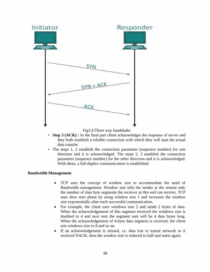
39
Fig3.4:Three way handshake
• Step 3 (ACK) : In the final part client acknowledges the response of server and
they both establish a reliable connection with which they will start the actual
data transfer
• The steps 1, 2 establish the connection parameter (sequence number) for one
direction and it is acknowledged. The steps 2, 3 establish the connection
parameter (sequence number) for the other direction and it is acknowledged.
With these, a full-duplex communication is established.
Bandwidth Management
• TCP uses the concept of window size to accommodate the need of
Bandwidth management. Window size tells the sender at the remote end,
the number of data byte segments the receiver at this end can receive. TCP
uses slow start phase by using window size 1 and increases the window
size exponentially after each successful communication.
• For example, the client uses windows size 2 and sends 2 bytes of data.
When the acknowledgement of this segment received the windows size is
doubled to 4 and next sent the segment sent will be 4 data bytes long.
When the acknowledgement of 4-byte data segment is received, the client
sets windows size to 8 and so on.
• If an acknowledgement is missed, i.e. data lost in transit network or it
received NACK, then the window size is reduced to half and starts again.
40
Error Control &and Flow Control
• TCP uses sequence numbers to synchronize itself with the remote host. All data
segments are sent and received with sequence numbers. The Sender knows which last
data segment was received by the Receiver
• when it gets ACK. The Receiver knows about the last segment sent by the Sender by
referring to the sequence number of recently received packet.
• If the sequence number of a segment recently received does not match with the
sequence number the receiver was expecting, then it is discarded and NACK is sent
back. If two segments arrive with the same sequence number, the TCP timestamp value
is compared to make a decision.
Congestion Control
• When large amount of data is fed to system which is not capable of
handling it, congestion occurs. TCP controls congestion by means of
Window mechanism. TCP sets a window size telling the other end how
much data segment to send. TCP may use three algorithms for congestion
control:
• Additive increase, Multiplicative Decrease
• Slow Start
• Timeout React
Timer Management
• TCP uses different types of timer to control and management various tasks:
• Keep-alive timer:
• This timer is used to check the integrity and validity of a connection.
• When keep-alive time expires, the host sends a probe to check if the connection
still exists.
• Retransmission timer:
• This timer maintains stateful session of data sent.
• If the acknowledgement of sent data does not receive within the Retransmission
time, the data segment is sent again.
• Persist timer:
• TCP session can be paused by either host by sending Window Size 0.
• To resume the session a host needs to send Window Size with some larger
value.
• If this segment never reaches the other end, both ends may wait for each other
for infinite time.
• When the Persist timer expires, the host re-sends its window size to let the other
end know.
• Persist Timer helps avoid deadlocks in communication.
• Timed-Wait:
• After releasing a connection, either of the hosts waits for a Timed-Wait time to
41
terminate the connection completely.
• This is in order to make sure that the other end has received the
acknowledgement of its connection termination request.
• Timed-out can be a maximum of 240 seconds (4 minutes).
Error Control in TCP
TCP protocol has methods for finding out corrupted segments, missing segments, out-of-order
segments and duplicated segments.
Error control in TCP is mainly done through use of three simple techniques :
Checksum – Every segment contains a checksum field which is used to find corrupted segment.
If the segment is corrupted, then that segment is discarded by the destination TCP and is
considered as lost
Acknowledgement – TCP has another mechanism called acknowledgement to affirm that the
data segments have been delivered.
Retransmission – When a segment is missing, delayed to deliver to receiver, corrupted when it
is checked by receiver then that segment is retransmitted again. Segments are retransmitted only
during two events: when the sender receives three duplicate acknowledgements (ACK) or when
a retransmission timer expires.
Retransmission after RTO : TCP always preserve one retransmission time-out (RTO) timer
for all sent but not acknowledged segments. When the timer runs out of time, the earliest
segment is retransmitted. Here no timer is set for acknowledgement. In TCP, RTO value is
dynamic in nature and it is updated using round trip time (RTT) of segments.
RTT(round trip time) is the time duration needed for a segment to reach receiver and an
acknowledgement to be received to the sender.
Retransmission after Three duplicate ACK segments : RTO method works well when the
value of RTO is small. If it is large, more time is needed to get confirmation about whether a
segment has delivered or not. Sometimes one segment is lost and the receiver receives so many
out-of-order segments that they cannot be saved. In order to solve this situation, three duplicate
acknowledgement method is used and missing segment is retransmitted immediately instead of
retransmitting already delivered segment. This is a fast retransmission because it makes it
possible to quickly retransmit lost segments instead of waiting for timer to end.
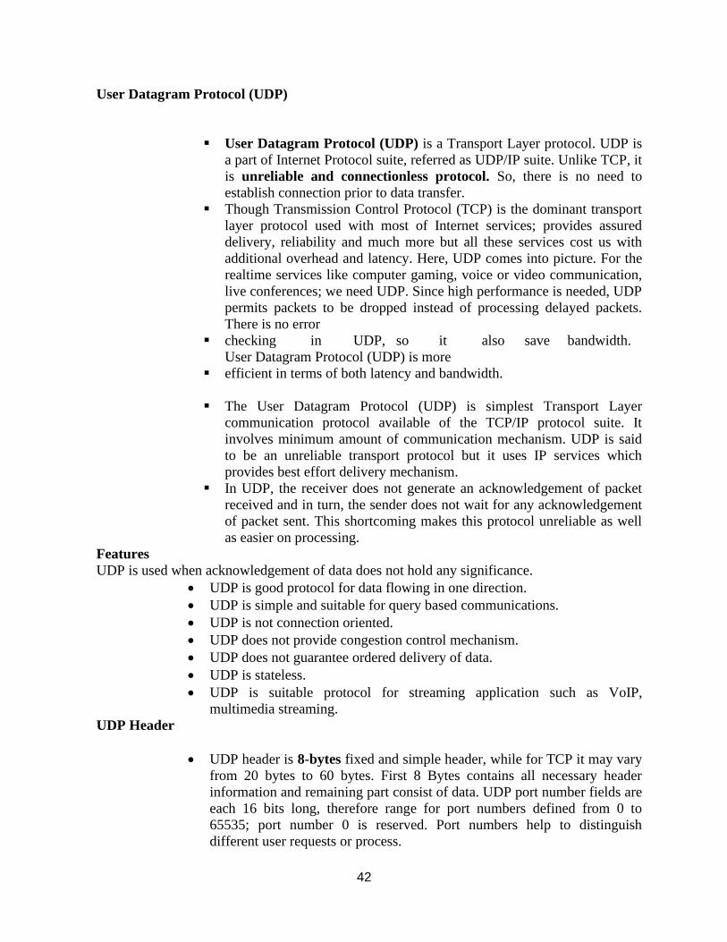
42
User Datagram Protocol (UDP)
▪ User Datagram Protocol (UDP) is a Transport Layer protocol. UDP is
a part of Internet Protocol suite, referred as UDP/IP suite. Unlike TCP, it
is unreliable and connectionless protocol. So, there is no need to
establish connection prior to data transfer.
▪ Though Transmission Control Protocol (TCP) is the dominant transport
layer protocol used with most of Internet services; provides assured
delivery, reliability and much more but all these services cost us with
additional overhead and latency. Here, UDP comes into picture. For the
realtime services like computer gaming, voice or video communication,
live conferences; we need UDP. Since high performance is needed, UDP
permits packets to be dropped instead of processing delayed packets.
There is no error
▪ checking in UDP, so it also save bandwidth.
User Datagram Protocol (UDP) is more
▪ efficient in terms of both latency and bandwidth.
▪ The User Datagram Protocol (UDP) is simplest Transport Layer
communication protocol available of the TCP/IP protocol suite. It
involves minimum amount of communication mechanism. UDP is said
to be an unreliable transport protocol but it uses IP services which
provides best effort delivery mechanism.
▪ In UDP, the receiver does not generate an acknowledgement of packet
received and in turn, the sender does not wait for any acknowledgement
of packet sent. This shortcoming makes this protocol unreliable as well
as easier on processing.
Features
UDP is used when acknowledgement of data does not hold any significance.
• UDP is good protocol for data flowing in one direction.
• UDP is simple and suitable for query based communications.
• UDP is not connection oriented.
• UDP does not provide congestion control mechanism.
• UDP does not guarantee ordered delivery of data.
• UDP is stateless.
• UDP is suitable protocol for streaming application such as VoIP,
multimedia streaming.
UDP Header
• UDP header is 8-bytes fixed and simple header, while for TCP it may vary
from 20 bytes to 60 bytes. First 8 Bytes contains all necessary header
information and remaining part consist of data. UDP port number fields are
each 16 bits long, therefore range for port numbers defined from 0 to
65535; port number 0 is reserved. Port numbers help to distinguish
different user requests or process.
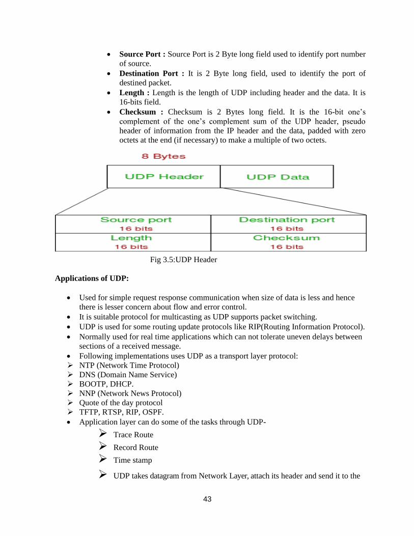
43
• Source Port : Source Port is 2 Byte long field used to identify port number
of source.
• Destination Port : It is 2 Byte long field, used to identify the port of
destined packet.
• Length : Length is the length of UDP including header and the data. It is
16-bits field.
• Checksum : Checksum is 2 Bytes long field. It is the 16-bit one’s
complement of the one’s complement sum of the UDP header, pseudo
header of information from the IP header and the data, padded with zero
octets at the end (if necessary) to make a multiple of two octets.
Fig 3.5:UDP Header
Applications of UDP:
• Used for simple request response communication when size of data is less and hence
there is lesser concern about flow and error control.
• It is suitable protocol for multicasting as UDP supports packet switching.
• UDP is used for some routing update protocols like RIP(Routing Information Protocol).
• Normally used for real time applications which can not tolerate uneven delays between
sections of a received message.
• Following implementations uses UDP as a transport layer protocol:
➢ NTP (Network Time Protocol)
➢ DNS (Domain Name Service)
➢ BOOTP, DHCP.
➢ NNP (Network News Protocol)
➢ Quote of the day protocol
➢ TFTP, RTSP, RIP, OSPF.
• Application layer can do some of the tasks through UDP-
➢ Trace Route
➢ Record Route
➢ Time stamp
➢ UDP takes datagram from Network Layer, attach its header and send it to the
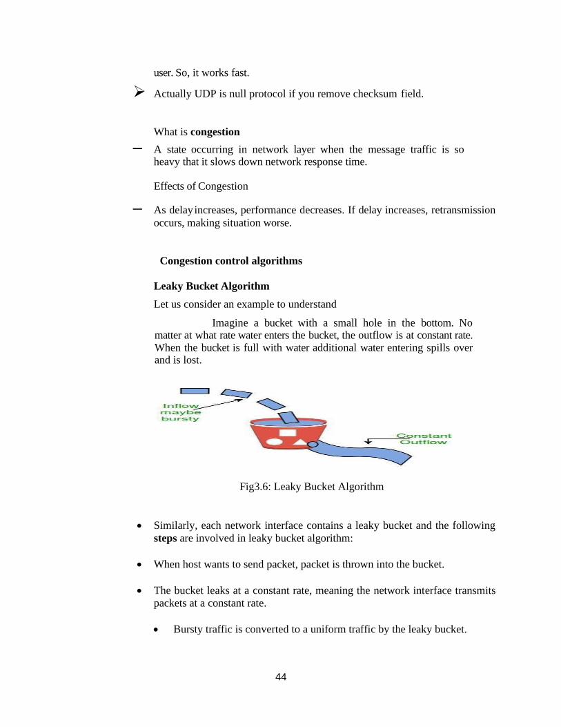
44
user. So, it works fast.
➢ Actually UDP is null protocol if you remove checksum field.
What is congestion
– A state occurring in network layer when the message traffic is so heavy that it slows down network response time. Effects of Congestion
– As delay increases, performance decreases. If delay increases, retransmission
occurs, making situation worse.
Congestion control algorithms
Leaky Bucket Algorithm
Let us consider an example to understand
Imagine a bucket with a small hole in the bottom. No matter at what rate water enters the bucket, the outflow is at constant rate. When the bucket is full with water additional water entering spills over and is lost.
Fig3.6: Leaky Bucket Algorithm
• Similarly, each network interface contains a leaky bucket and the following
steps are involved in leaky bucket algorithm:
• When host wants to send packet, packet is thrown into the bucket.
• The bucket leaks at a constant rate, meaning the network interface transmits
packets at a constant rate.
• Bursty traffic is converted to a uniform traffic by the leaky bucket.
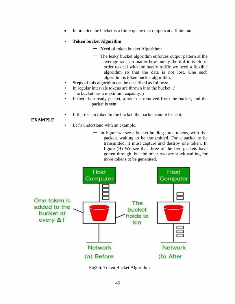
45
• In practice the bucket is a finite queue that outputs at a finite rate.
• Token bucket Algorithm
– Need of token bucket Algorithm:-
– The leaky bucket algorithm enforces output pattern at the
average rate, no matter how bursty the traffic is. So in
order to deal with the bursty traffic we need a flexible
algorithm so that the data is not lost. One such
algorithm is token bucket algorithm.
• Steps of this algorithm can be described as follows:
• In regular intervals tokens are thrown into the bucket. ƒ
• The bucket has a maximum capacity. ƒ
• If there is a ready packet, a token is removed from the bucket, and the
packet is sent.
• If there is no token in the bucket, the packet cannot be sent.
EXAMPLE
• Let’s understand with an example,
– In figure we see a bucket holding three tokens, with five
packets waiting to be transmitted. For a packet to be
transmitted, it must capture and destroy one token. In
figure (B) We see that three of the five packets have
gotten through, but the other two are stuck waiting for
more tokens to be generated.
Fig3.6: Token Bucket Algorithm
46
Ways in which token bucket is superior to leaky bucket
• The leaky bucket algorithm controls the rate at which the packets are introduced in the
network, but it is very conservative in nature.
• Some flexibility is introduced in the token bucket algorithm. In the token bucket,
algorithm tokens are generated at each tick (up to a certain limit).
• For an incoming packet to be transmitted, it must capture a token and the transmission
takes place at the same rate.
• Hence some of the busty packets are transmitted at the same rate if tokens are available
and thus introduces some amount of flexibility in the system.
Formula:
M * s = C + ρ * s where S – is time taken
M – Maximum output rate ρ – Token arrival rate , C – Capacity of the token bucket in byte
Leaky Bucket vs Token Bucket
▪ LB discards packets; TB does not. TB discards tokens.
▪ With TB, a packet can only be transmitted if there are enough tokens
▪ LB sends packets at an average rate. TB allows for large bursts to be sent
faster by speeding up the output.
▪ TB allows saving up tokens (permissions) to send large bursts. LB does not
allow saving.
TEXT / REFERENCE BOOKS
1. Behrouz A. Fourouzan, “Data Communication and Networking”, McGraw-Hill
Education India Pvt. Ltd - New Delhi.
2. William Stallings, Data and Computer Communications (8th ed.), Pearson
Education, 2007.
3. P.C. Gupta, Data Communications and Computer Networks, Prentice-Hall of
India, 2006.
4. Andrew S. Tanenbaum, “Computer Networks”, Fourth Edition, Pearson.
5. L. Peterson and B. S. Davie, Computer Networks: A Systems Approach (3rd
ed.), Morgan Kaufmann, 2003
47
QUESTIONS
PARTA
1. What are the functions of transport layer?
2. Compare connectionless service & connection oriented service
3. What is RTT?
4. List the flag used in TCP header
5. Why TCP services are called Stream delivery services?
6. Define Throughput
7. What is the need of port numbers?
8. What are the two types of protocols used in Transport layer?
9. What are the techniques to improve QoS?
10. Define network congestion
11. List some ways to deal with congestion
12. What are the advantages of using UDP over TCP?
PART B
13. Explain the concept CONGESTION CONTROL ALGORTIHM
14. Explain about UDP.
15. Write about TCP services.
16. What are the features of TCP?
17. Write about TCP segment?
18. Write about different steps to create a TCP Connection.
19. Write about Flow Control in TCP.
20. Write about Error Control in TCP.
48
UNIT – V – Data communication and Computer networks – SITA1401
SCHOOL OF COMPUTING
DEPARTMENT OF INFORMATION TECHNOLOGY
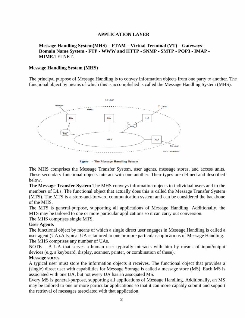
2
APPLICATION LAYER
Message Handling System(MHS) – FTAM – Virtual Terminal (VT) – Gateways-
Domain Name System - FTP - WWW and HTTP - SNMP - SMTP - POP3 - IMAP -
MIME-TELNET.
Message Handling System (MHS)
The principal purpose of Message Handling is to convey information objects from one party to another. The
functional object by means of which this is accomplished is called the Message Handling System (MHS).
The MHS comprises the Message Transfer System, user agents, message stores, and access units.
These secondary functional objects interact with one another. Their types are defined and described
below.
The Message Transfer System The MHS conveys information objects to individual users and to the
members of DLs. The functional object that actually does this is called the Message Transfer System
(MTS). The MTS is a store-and-forward communication system and can be considered the backbone
of the MHS.
The MTS is general-purpose, supporting all applications of Message Handling. Additionally, the
MTS may be tailored to one or more particular applications so it can carry out conversion.
The MHS comprises single MTS.
User Agents
The functional object by means of which a single direct user engages in Message Handling is called a
user agent (UA).A typical UA is tailored to one or more particular applications of Message Handling.
The MHS comprises any number of UAs.
NOTE – A UA that serves a human user typically interacts with him by means of input/output
devices (e.g. a keyboard, display, scanner, printer, or combination of these).
Message stores
A typical user must store the information objects it receives. The functional object that provides a
(single) direct user with capabilities for Message Storage is called a message store (MS). Each MS is
associated with one UA, but not every UA has an associated MS.
Every MS is general-purpose, supporting all applications of Message Handling. Additionally, an MS
may be tailored to one or more particular applications so that it can more capably submit and support
the retrieval of messages associated with that application.
3
The MHS comprises any number of MSs.
NOTE – As a local matter a UA may provide for information objects storage that either supplements
or replaces that of an MS.
Access units
The functional object that links another communication system (e.g. a postal system or the telex
network) to the MTS and via which its patrons engage in Message Handling as indirect users is called
an access unit (AU).A typical AU is tailored to a particular communication system and to one or
more particular applications of Message Handling.The MHS comprises any number of AUs.
File Transfer, Access, and Management (FTAM):
An application allows a user to access files in a remote computer, to retrieve files from a computer
and to manage files in a remote computer. FTAM defines a hierarchical virtual file in terms of file
structure, file attributes and the kind of operations performed on the files and their attributes.
Network Virtual terminal: An application layer allows a user to log on to a remote host. To do so,
the application creates a software emulation of a terminal at the remote host. The user's computer
talks to the software terminal, which in turn, talks to the host. The remote host thinks that it is
communicating with one of its own terminals, so it allows the user to log on.
DOMAIN NAME SYSTEM
Generally host names, mailboxes and other resources are represented by using ASCII sting such
as [email protected] the network itself only understands binary address i.e., the address written
in the binary form. So we need some mechanism to convert the ASCII strings to network
addresses in binary. It is easy to maintain the host names and their IP addresses in file for a
network of few hundred hosts. For a network of thousand hosts it is very difficult.
The Domain Name System, DNS is a distributes data that is used by TCP/IP application to map
between host names and IP addresses, and to provide electronic mail routing information. We use
the term distributed because no single site on the Internet knows all the information. Each site
maintains its own data base information and runs a server program that other systems (clients)
across the Internet can query. It is a good example of a TCP/IP client-server application.
The DNS provides the protocol that allows client and server to communicate with each other.
DNS is defined in RFC’s 1034 and 1035.
The DNS identifies each host on the internet with a unique name that identifies it as
unambiguously as its IP address as follows. To map a name onto an IP address, an application
program calls a library procedure called the resolver, passing it the name as a parameter. The
‘resolver’ sends a UDP packet to a local DNS server, which then looks up the name and returns
the IP address to the resolver, which then returns it to the caller. To create names that are unique
and at the same time decentralized and easy to change, the TCP/IP designers have chosen a
hierarchical system made up of a number of labels separated by dots.
THE DNS NAME SPACE
Internet is divided it several hundred top level domains, where each domain covers many hosts.
Each domain is partitioned into sub domains, these are further partitioned and so on. Thus DNS is
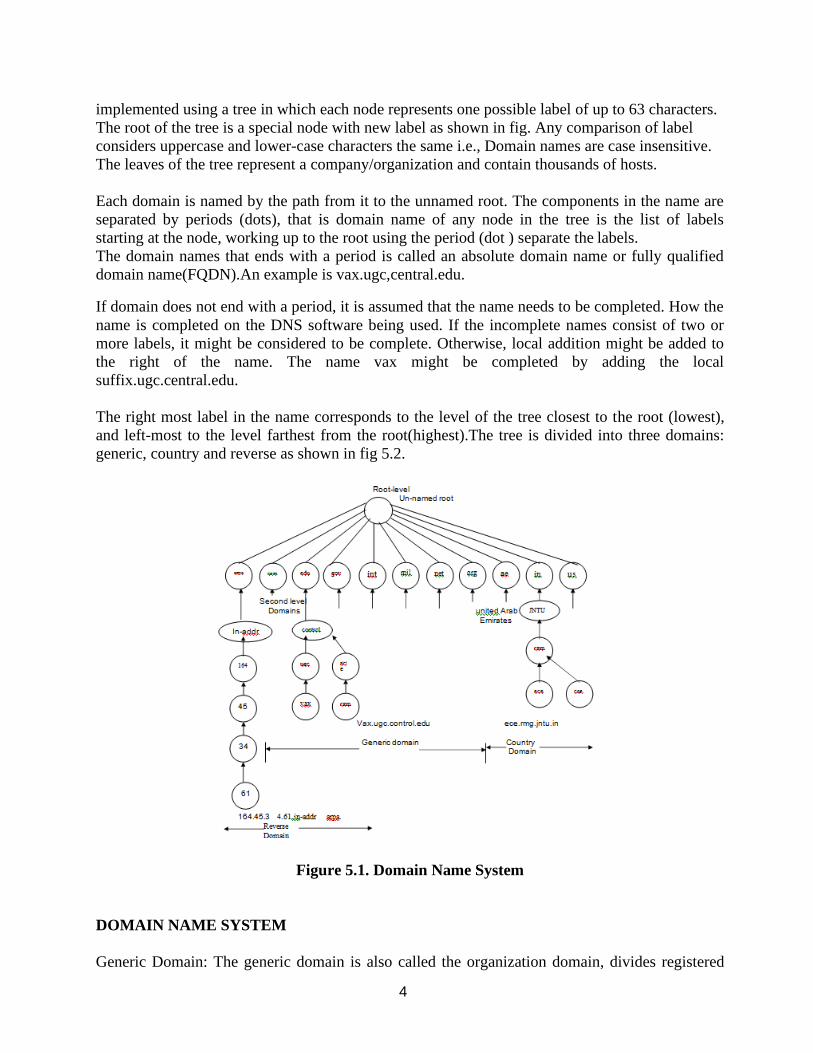
4
implemented using a tree in which each node represents one possible label of up to 63 characters.
The root of the tree is a special node with new label as shown in fig. Any comparison of label
considers uppercase and lower-case characters the same i.e., Domain names are case insensitive.
The leaves of the tree represent a company/organization and contain thousands of hosts.
Each domain is named by the path from it to the unnamed root. The components in the name are
separated by periods (dots), that is domain name of any node in the tree is the list of labels
starting at the node, working up to the root using the period (dot ) separate the labels.
The domain names that ends with a period is called an absolute domain name or fully qualified
domain name(FQDN).An example is vax.ugc,central.edu.
If domain does not end with a period, it is assumed that the name needs to be completed. How the
name is completed on the DNS software being used. If the incomplete names consist of two or
more labels, it might be considered to be complete. Otherwise, local addition might be added to
the right of the name. The name vax might be completed by adding the local
suffix.ugc.central.edu.
The right most label in the name corresponds to the level of the tree closest to the root (lowest),
and left-most to the level farthest from the root(highest).The tree is divided into three domains:
generic, country and reverse as shown in fig 5.2.
Figure 5.1. Domain Name System
DOMAIN NAME SYSTEM
Generic Domain: The generic domain is also called the organization domain, divides registered

5
hosts according to their generic behaviour. Generic domain names, read left to the right , start
with the most specific information about the host(e.g. the name of the workstation) and become
more and more general with each label until they reach the rightmost label, which describes the
broadcast affiliation of the normal host i.e., the nature of the organization.
The first level of the generic domain convention allows seven possible three character labels
describing organization type.
1. Com. commercial organization.
2. edu.: educational institution .
3. gov.: government institution.
4. int.: international organization.
5. mil.: military group.
6. net.: Network support center.
7. org. organizations other than listed above.
Each domain name corresponds to a particular IP address. To find the address, the resolution
application begins searching with the first level. As a much is found, a pointer leads to the next
level and finally to the associated IP address.
Country Domain: The country domain convention follows the same format as generic domain,
but uses two character country abbreviation in place of three character organizational
abbreviations at the first level shown in table. Second level labels can be organizational or they
can be more specific national designations.
Table: SOME DOMAIN NAME SYSTEM COUNTRY CODE
Country Code
Country Name
Country Code
Country Name
AE AU BE CA C DE
DK ES FI
Arubeme rate
Australia Belgium
Canada Switzerlan
Germany Denmar
Spain
Finland
IN IT JP KW NL NO
NZ SE US
India Italy Japa
Kuwait
Netherlands Norwa
Newzeland Sweden
United States o
America
GR
Greece
Reverse Domain: If we have the IP address and need the domain name, you can reverse domain
the functions of DNS.
The domain can be inserted onto the tree in two ways. For example ugc.control.edu could equally
be listed under the country domain as cs.yale.ct.us.
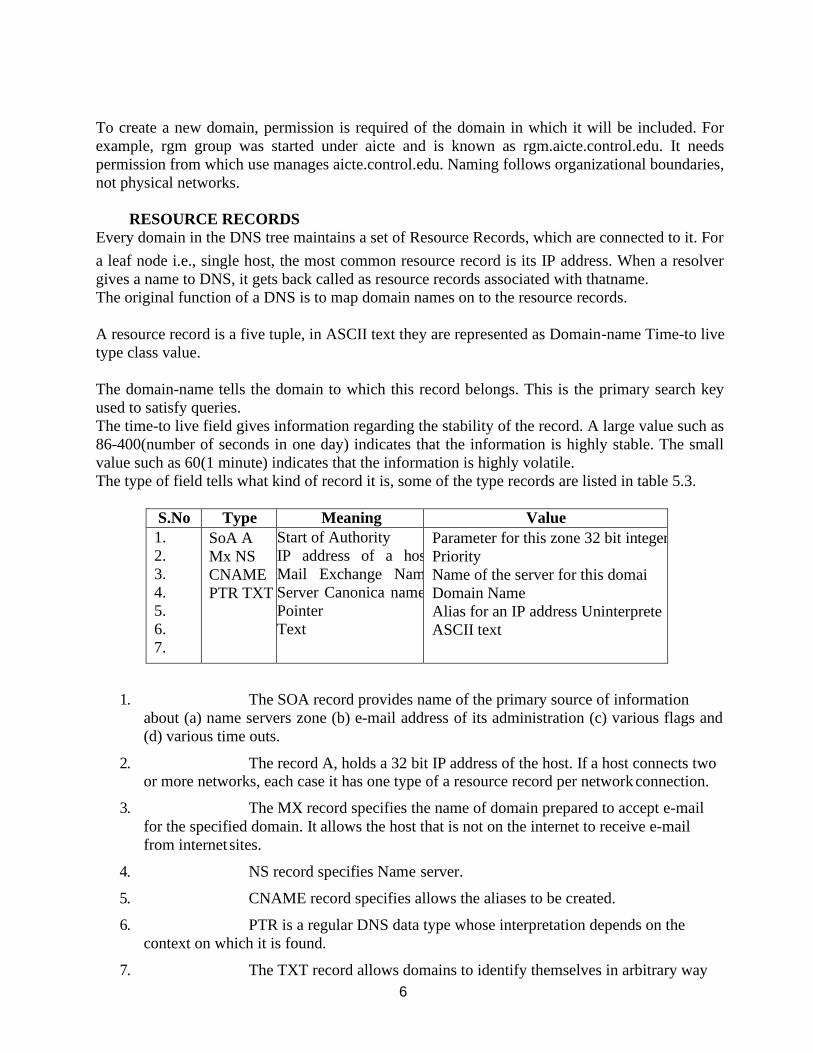
6
To create a new domain, permission is required of the domain in which it will be included. For
example, rgm group was started under aicte and is known as rgm.aicte.control.edu. It needs
permission from which use manages aicte.control.edu. Naming follows organizational boundaries,
not physical networks.
RESOURCE RECORDS
Every domain in the DNS tree maintains a set of Resource Records, which are connected to it. For
a leaf node i.e., single host, the most common resource record is its IP address. When a resolver
gives a name to DNS, it gets back called as resource records associated with thatname.
The original function of a DNS is to map domain names on to the resource records.
A resource record is a five tuple, in ASCII text they are represented as Domain-name Time-to live
type class value.
The domain-name tells the domain to which this record belongs. This is the primary search key
used to satisfy queries.
The time-to live field gives information regarding the stability of the record. A large value such as
86-400(number of seconds in one day) indicates that the information is highly stable. The small
value such as 60(1 minute) indicates that the information is highly volatile.
The type of field tells what kind of record it is, some of the type records are listed in table 5.3.
S.No Type Meaning Value
1.
2.
3.
4.
5.
6.
7.
SoA A
Mx NS
CNAME
PTR TXT
Start of Authority
IP address of a hos
Mail Exchange Nam
Server Canonica name
Pointer
Text
Parameter for this zone 32 bit integer
Priority
Name of the server for this domai
Domain Name
Alias for an IP address Uninterprete
ASCII text
1. The SOA record provides name of the primary source of information
about (a) name servers zone (b) e-mail address of its administration (c) various flags and
(d) various time outs.
2. The record A, holds a 32 bit IP address of the host. If a host connects two or more networks, each case it has one type of a resource record per network connection.
3. The MX record specifies the name of domain prepared to accept e-mail
for the specified domain. It allows the host that is not on the internet to receive e-mail
from internet sites.
4. NS record specifies Name server.
5. CNAME record specifies allows the aliases to be created.
6. PTR is a regular DNS data type whose interpretation depends on the
context on which it is found.
7. The TXT record allows domains to identify themselves in arbitrary way
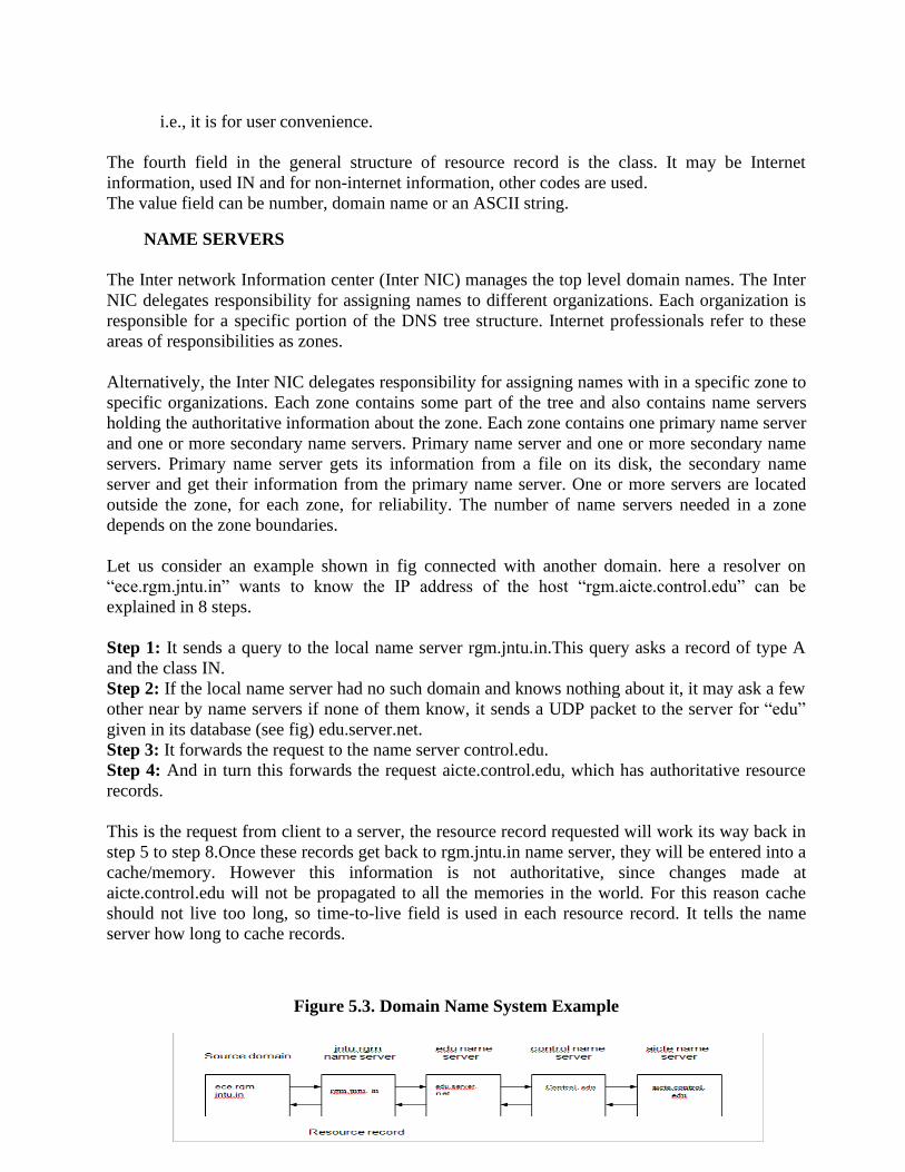
7
i.e., it is for user convenience.
The fourth field in the general structure of resource record is the class. It may be Internet
information, used IN and for non-internet information, other codes are used.
The value field can be number, domain name or an ASCII string.
NAME SERVERS
The Inter network Information center (Inter NIC) manages the top level domain names. The Inter
NIC delegates responsibility for assigning names to different organizations. Each organization is
responsible for a specific portion of the DNS tree structure. Internet professionals refer to these
areas of responsibilities as zones.
Alternatively, the Inter NIC delegates responsibility for assigning names with in a specific zone to
specific organizations. Each zone contains some part of the tree and also contains name servers
holding the authoritative information about the zone. Each zone contains one primary name server
and one or more secondary name servers. Primary name server and one or more secondary name
servers. Primary name server gets its information from a file on its disk, the secondary name
server and get their information from the primary name server. One or more servers are located
outside the zone, for each zone, for reliability. The number of name servers needed in a zone
depends on the zone boundaries.
Let us consider an example shown in fig connected with another domain. here a resolver on
“ece.rgm.jntu.in” wants to know the IP address of the host “rgm.aicte.control.edu” can be
explained in 8 steps.
Step 1: It sends a query to the local name server rgm.jntu.in.This query asks a record of type A
and the class IN.
Step 2: If the local name server had no such domain and knows nothing about it, it may ask a few
other near by name servers if none of them know, it sends a UDP packet to the server for “edu”
given in its database (see fig) edu.server.net.
Step 3: It forwards the request to the name server control.edu.
Step 4: And in turn this forwards the request aicte.control.edu, which has authoritative resource
records.
This is the request from client to a server, the resource record requested will work its way back in
step 5 to step 8.Once these records get back to rgm.jntu.in name server, they will be entered into a
cache/memory. However this information is not authoritative, since changes made at
aicte.control.edu will not be propagated to all the memories in the world. For this reason cache
should not live too long, so time-to-live field is used in each resource record. It tells the name
server how long to cache records.
Figure 5.3. Domain Name System Example
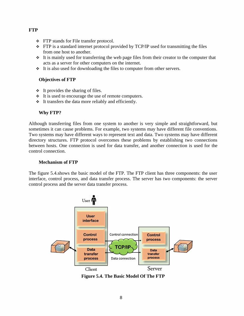
8
FTP
❖ FTP stands for File transfer protocol.
❖ FTP is a standard internet protocol provided by TCP/IP used for transmitting the files
from one host to another.
❖ It is mainly used for transferring the web page files from their creator to the computer that
acts as a server for other computers on the internet.
❖ It is also used for downloading the files to computer from other servers.
Objectives of FTP
❖ It provides the sharing of files.
❖ It is used to encourage the use of remote computers.
❖ It transfers the data more reliably and efficiently.
Why FTP?
Although transferring files from one system to another is very simple and straightforward, but
sometimes it can cause problems. For example, two systems may have different file conventions.
Two systems may have different ways to represent text and data. Two systems may have different
directory structures. FTP protocol overcomes these problems by establishing two connections
between hosts. One connection is used for data transfer, and another connection is used for the
control connection.
Mechanism of FTP
The figure 5.4.shows the basic model of the FTP. The FTP client has three components: the user
interface, control process, and data transfer process. The server has two components: the server
control process and the server data transfer process.
Figure 5.4. The Basic Model Of The FTP
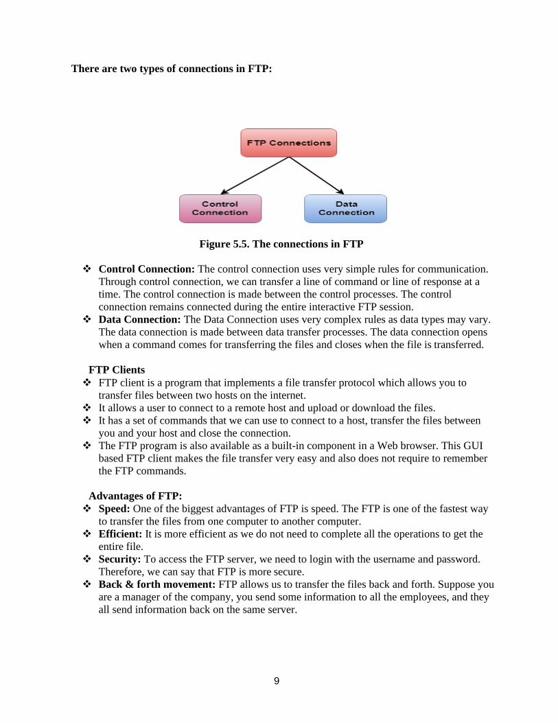
9
There are two types of connections in FTP:
Figure 5.5. The connections in FTP
❖ Control Connection: The control connection uses very simple rules for communication.
Through control connection, we can transfer a line of command or line of response at a
time. The control connection is made between the control processes. The control
connection remains connected during the entire interactive FTP session.
❖ Data Connection: The Data Connection uses very complex rules as data types may vary.
The data connection is made between data transfer processes. The data connection opens
when a command comes for transferring the files and closes when the file is transferred.
FTP Clients
❖ FTP client is a program that implements a file transfer protocol which allows you to
transfer files between two hosts on the internet.
❖ It allows a user to connect to a remote host and upload or download the files.
❖ It has a set of commands that we can use to connect to a host, transfer the files between
you and your host and close the connection.
❖ The FTP program is also available as a built-in component in a Web browser. This GUI
based FTP client makes the file transfer very easy and also does not require to remember
the FTP commands.
Advantages of FTP:
❖ Speed: One of the biggest advantages of FTP is speed. The FTP is one of the fastest way
to transfer the files from one computer to another computer.
❖ Efficient: It is more efficient as we do not need to complete all the operations to get the
entire file.
❖ Security: To access the FTP server, we need to login with the username and password.
Therefore, we can say that FTP is more secure.
❖ Back & forth movement: FTP allows us to transfer the files back and forth. Suppose you
are a manager of the company, you send some information to all the employees, and they
all send information back on the same server.
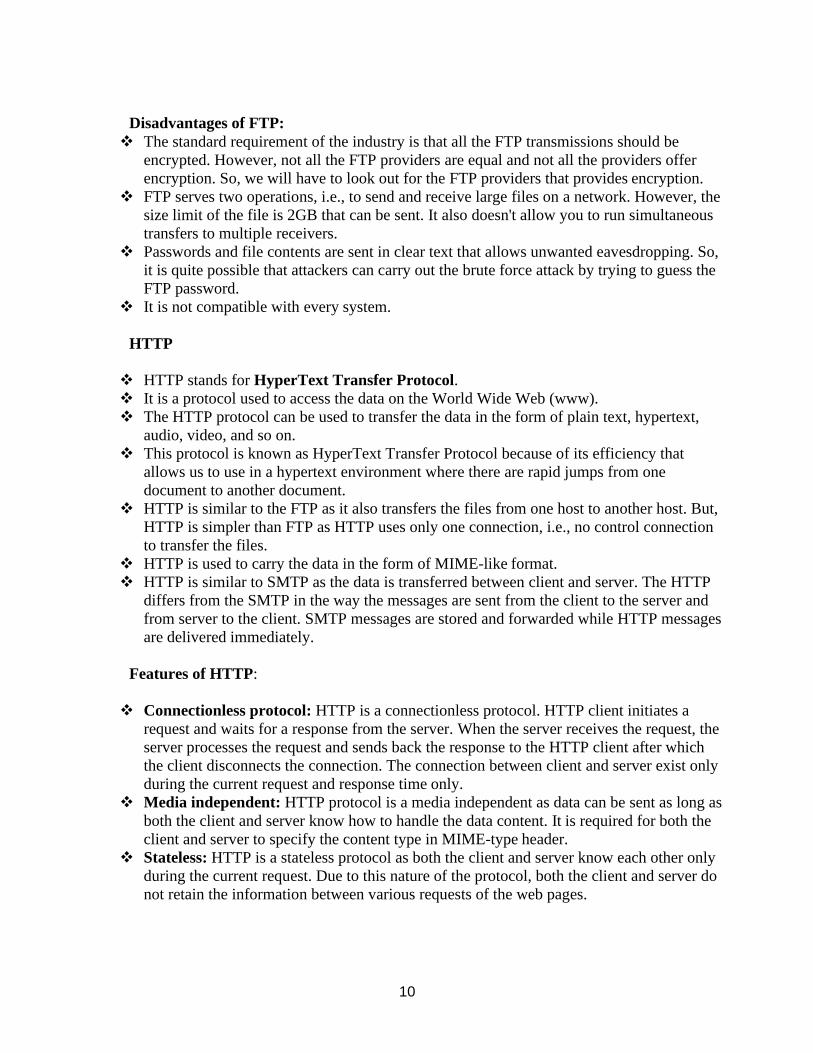
10
Disadvantages of FTP:
❖ The standard requirement of the industry is that all the FTP transmissions should be
encrypted. However, not all the FTP providers are equal and not all the providers offer
encryption. So, we will have to look out for the FTP providers that provides encryption.
❖ FTP serves two operations, i.e., to send and receive large files on a network. However, the
size limit of the file is 2GB that can be sent. It also doesn't allow you to run simultaneous
transfers to multiple receivers.
❖ Passwords and file contents are sent in clear text that allows unwanted eavesdropping. So,
it is quite possible that attackers can carry out the brute force attack by trying to guess the
FTP password.
❖ It is not compatible with every system.
HTTP
❖ HTTP stands for HyperText Transfer Protocol.
❖ It is a protocol used to access the data on the World Wide Web (www).
❖ The HTTP protocol can be used to transfer the data in the form of plain text, hypertext,
audio, video, and so on.
❖ This protocol is known as HyperText Transfer Protocol because of its efficiency that
allows us to use in a hypertext environment where there are rapid jumps from one
document to another document.
❖ HTTP is similar to the FTP as it also transfers the files from one host to another host. But,
HTTP is simpler than FTP as HTTP uses only one connection, i.e., no control connection
to transfer the files.
❖ HTTP is used to carry the data in the form of MIME-like format.
❖ HTTP is similar to SMTP as the data is transferred between client and server. The HTTP
differs from the SMTP in the way the messages are sent from the client to the server and
from server to the client. SMTP messages are stored and forwarded while HTTP messages
are delivered immediately.
Features of HTTP:
❖ Connectionless protocol: HTTP is a connectionless protocol. HTTP client initiates a
request and waits for a response from the server. When the server receives the request, the
server processes the request and sends back the response to the HTTP client after which
the client disconnects the connection. The connection between client and server exist only
during the current request and response time only.
❖ Media independent: HTTP protocol is a media independent as data can be sent as long as
both the client and server know how to handle the data content. It is required for both the
client and server to specify the content type in MIME-type header.
❖ Stateless: HTTP is a stateless protocol as both the client and server know each other only
during the current request. Due to this nature of the protocol, both the client and server do
not retain the information between various requests of the web pages.
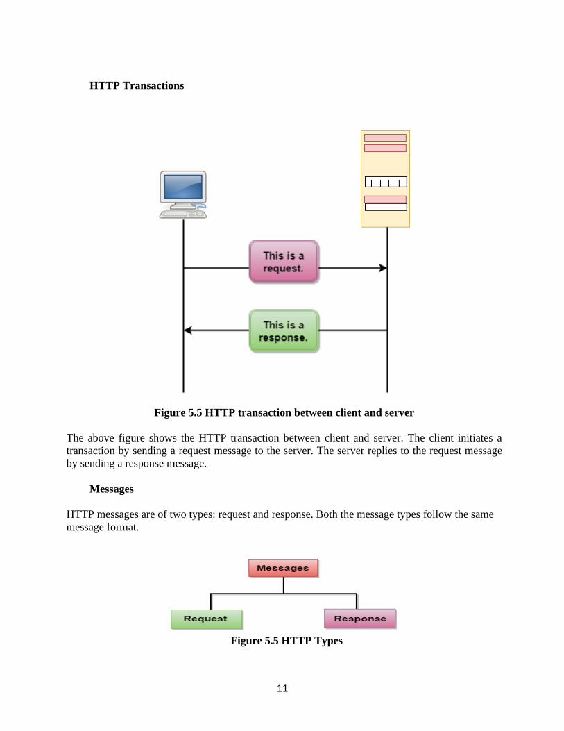
11
HTTP Transactions
Figure 5.5 HTTP transaction between client and server
The above figure shows the HTTP transaction between client and server. The client initiates a
transaction by sending a request message to the server. The server replies to the request message
by sending a response message.
Messages
HTTP messages are of two types: request and response. Both the message types follow the same
message format.
Figure 5.5 HTTP Types
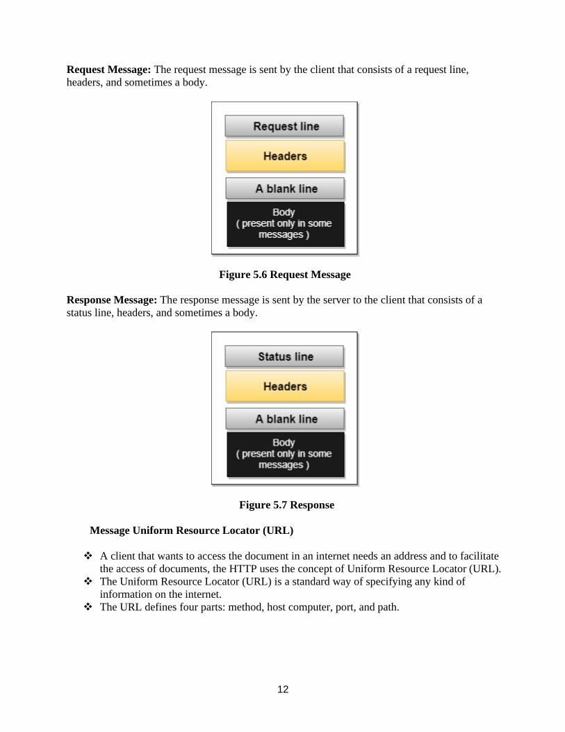
12
Request Message: The request message is sent by the client that consists of a request line,
headers, and sometimes a body.
Figure 5.6 Request Message
Response Message: The response message is sent by the server to the client that consists of a
status line, headers, and sometimes a body.
Figure 5.7 Response
Message Uniform Resource Locator (URL)
❖ A client that wants to access the document in an internet needs an address and to facilitate
the access of documents, the HTTP uses the concept of Uniform Resource Locator (URL).
❖ The Uniform Resource Locator (URL) is a standard way of specifying any kind of
information on the internet.
❖ The URL defines four parts: method, host computer, port, and path.
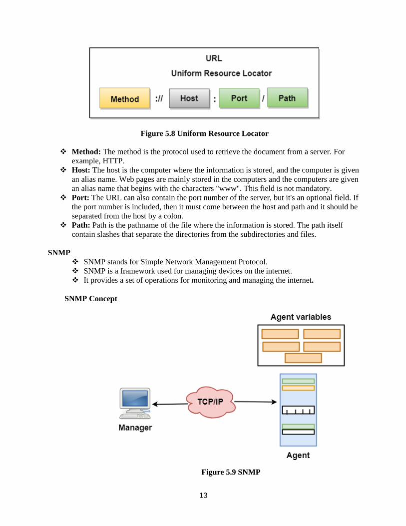
13
Figure 5.8 Uniform Resource Locator
❖ Method: The method is the protocol used to retrieve the document from a server. For
example, HTTP.
❖ Host: The host is the computer where the information is stored, and the computer is given
an alias name. Web pages are mainly stored in the computers and the computers are given
an alias name that begins with the characters "www". This field is not mandatory.
❖ Port: The URL can also contain the port number of the server, but it's an optional field. If
the port number is included, then it must come between the host and path and it should be
separated from the host by a colon.
❖ Path: Path is the pathname of the file where the information is stored. The path itself
contain slashes that separate the directories from the subdirectories and files.
SNMP ❖ SNMP stands for Simple Network Management Protocol.
❖ SNMP is a framework used for managing devices on the internet.
❖ It provides a set of operations for monitoring and managing the internet.
SNMP Concept
Figure 5.9 SNMP
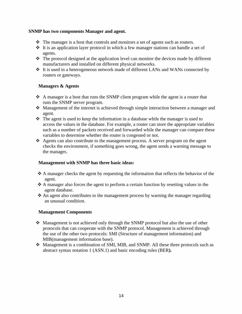
14
SNMP has two components Manager and agent.
❖ The manager is a host that controls and monitors a set of agents such as routers.
❖ It is an application layer protocol in which a few manager stations can handle a set of
agents.
❖ The protocol designed at the application level can monitor the devices made by different
manufacturers and installed on different physical networks.
❖ It is used in a heterogeneous network made of different LANs and WANs connected by
routers or gateways.
Managers & Agents
❖ A manager is a host that runs the SNMP client program while the agent is a router that
runs the SNMP server program.
❖ Management of the internet is achieved through simple interaction between a manager and
agent.
❖ The agent is used to keep the information in a database while the manager is used to
access the values in the database. For example, a router can store the appropriate variables
such as a number of packets received and forwarded while the manager can compare these
variables to determine whether the router is congested or not.
❖ Agents can also contribute to the management process. A server program on the agent
checks the environment, if something goes wrong, the agent sends a warning message to
the manager.
Management with SNMP has three basic ideas:
❖ A manager checks the agent by requesting the information that reflects the behavior of the
agent.
❖ A manager also forces the agent to perform a certain function by resetting values in the
agent database.
❖ An agent also contributes to the management process by warning the manager regarding
an unusual condition.
Management Components
❖ Management is not achieved only through the SNMP protocol but also the use of other
protocols that can cooperate with the SNMP protocol. Management is achieved through
the use of the other two protocols: SMI (Structure of management information) and
MIB(management information base).
❖ Management is a combination of SMI, MIB, and SNMP. All these three protocols such as
abstract syntax notation 1 (ASN.1) and basic encoding rules (BER).
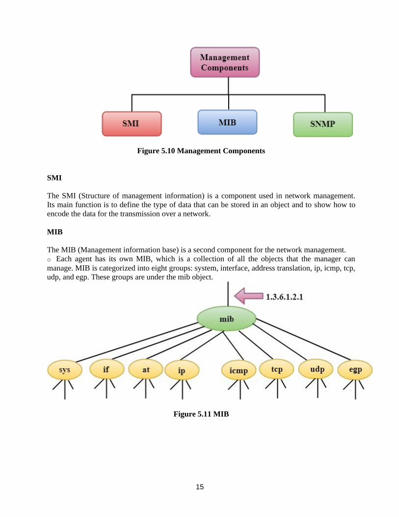
15
Figure 5.10 Management Components
SMI
The SMI (Structure of management information) is a component used in network management.
Its main function is to define the type of data that can be stored in an object and to show how to
encode the data for the transmission over a network.
MIB
The MIB (Management information base) is a second component for the network management.
o Each agent has its own MIB, which is a collection of all the objects that the manager can
manage. MIB is categorized into eight groups: system, interface, address translation, ip, icmp, tcp,
udp, and egp. These groups are under the mib object.
Figure 5.11 MIB
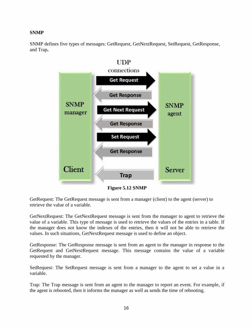
16
SNMP
SNMP defines five types of messages: GetRequest, GetNextRequest, SetRequest, GetResponse,
and Trap.
Figure 5.12 SNMP
GetRequest: The GetRequest message is sent from a manager (client) to the agent (server) to
retrieve the value of a variable.
GetNextRequest: The GetNextRequest message is sent from the manager to agent to retrieve the
value of a variable. This type of message is used to retrieve the values of the entries in a table. If
the manager does not know the indexes of the entries, then it will not be able to retrieve the
values. In such situations, GetNextRequest message is used to define an object.
GetResponse: The GetResponse message is sent from an agent to the manager in response to the
GetRequest and GetNextRequest message. This message contains the value of a variable
requested by the manager.
SetRequest: The SetRequest message is sent from a manager to the agent to set a value in a
variable.
Trap: The Trap message is sent from an agent to the manager to report an event. For example, if
the agent is rebooted, then it informs the manager as well as sends the time of rebooting.
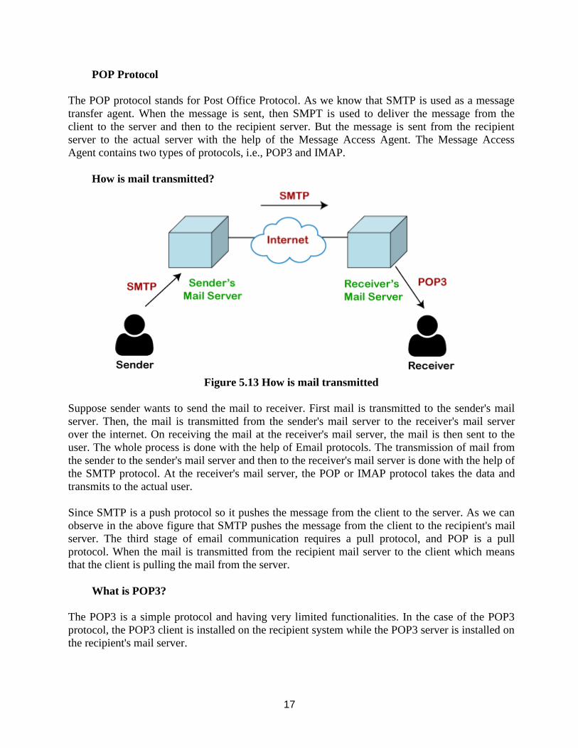
17
POP Protocol
The POP protocol stands for Post Office Protocol. As we know that SMTP is used as a message
transfer agent. When the message is sent, then SMPT is used to deliver the message from the
client to the server and then to the recipient server. But the message is sent from the recipient
server to the actual server with the help of the Message Access Agent. The Message Access
Agent contains two types of protocols, i.e., POP3 and IMAP.
How is mail transmitted?
Figure 5.13 How is mail transmitted
Suppose sender wants to send the mail to receiver. First mail is transmitted to the sender's mail
server. Then, the mail is transmitted from the sender's mail server to the receiver's mail server
over the internet. On receiving the mail at the receiver's mail server, the mail is then sent to the
user. The whole process is done with the help of Email protocols. The transmission of mail from
the sender to the sender's mail server and then to the receiver's mail server is done with the help of
the SMTP protocol. At the receiver's mail server, the POP or IMAP protocol takes the data and
transmits to the actual user.
Since SMTP is a push protocol so it pushes the message from the client to the server. As we can
observe in the above figure that SMTP pushes the message from the client to the recipient's mail
server. The third stage of email communication requires a pull protocol, and POP is a pull
protocol. When the mail is transmitted from the recipient mail server to the client which means
that the client is pulling the mail from the server.
What is POP3?
The POP3 is a simple protocol and having very limited functionalities. In the case of the POP3
protocol, the POP3 client is installed on the recipient system while the POP3 server is installed on
the recipient's mail server.
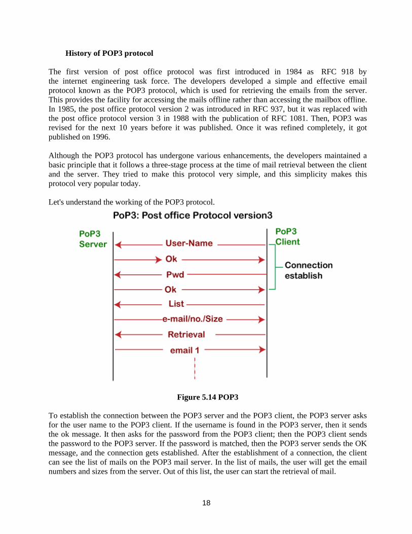
18
History of POP3 protocol
The first version of post office protocol was first introduced in 1984 as RFC 918 by
the internet engineering task force. The developers developed a simple and effective email
protocol known as the POP3 protocol, which is used for retrieving the emails from the server.
This provides the facility for accessing the mails offline rather than accessing the mailbox offline.
In 1985, the post office protocol version 2 was introduced in RFC 937, but it was replaced with
the post office protocol version 3 in 1988 with the publication of RFC 1081. Then, POP3 was
revised for the next 10 years before it was published. Once it was refined completely, it got
published on 1996.
Although the POP3 protocol has undergone various enhancements, the developers maintained a
basic principle that it follows a three-stage process at the time of mail retrieval between the client
and the server. They tried to make this protocol very simple, and this simplicity makes this
protocol very popular today.
Let's understand the working of the POP3 protocol.
Figure 5.14 POP3
To establish the connection between the POP3 server and the POP3 client, the POP3 server asks
for the user name to the POP3 client. If the username is found in the POP3 server, then it sends
the ok message. It then asks for the password from the POP3 client; then the POP3 client sends
the password to the POP3 server. If the password is matched, then the POP3 server sends the OK
message, and the connection gets established. After the establishment of a connection, the client
can see the list of mails on the POP3 mail server. In the list of mails, the user will get the email
numbers and sizes from the server. Out of this list, the user can start the retrieval of mail.
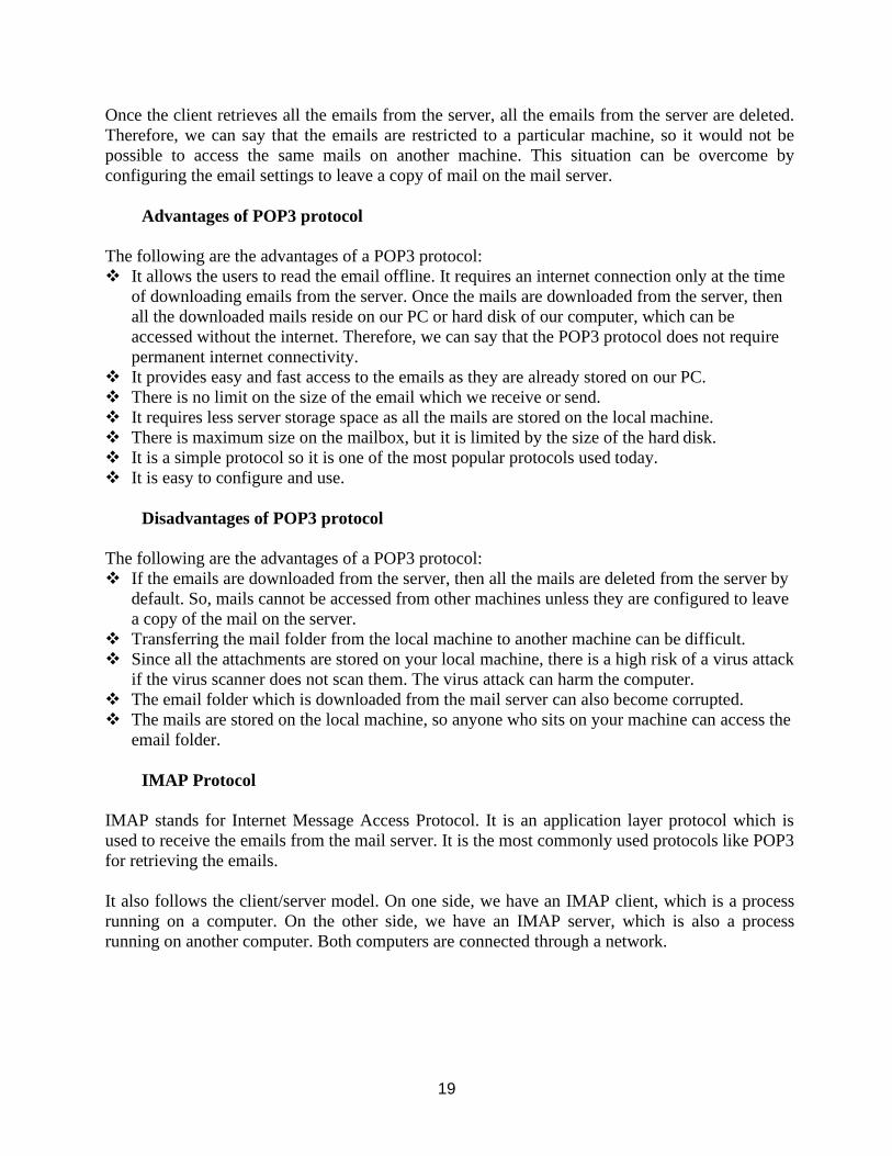
19
Once the client retrieves all the emails from the server, all the emails from the server are deleted.
Therefore, we can say that the emails are restricted to a particular machine, so it would not be
possible to access the same mails on another machine. This situation can be overcome by
configuring the email settings to leave a copy of mail on the mail server.
Advantages of POP3 protocol
The following are the advantages of a POP3 protocol:
❖ It allows the users to read the email offline. It requires an internet connection only at the time
of downloading emails from the server. Once the mails are downloaded from the server, then
all the downloaded mails reside on our PC or hard disk of our computer, which can be
accessed without the internet. Therefore, we can say that the POP3 protocol does not require
permanent internet connectivity.
❖ It provides easy and fast access to the emails as they are already stored on our PC.
❖ There is no limit on the size of the email which we receive or send.
❖ It requires less server storage space as all the mails are stored on the local machine.
❖ There is maximum size on the mailbox, but it is limited by the size of the hard disk.
❖ It is a simple protocol so it is one of the most popular protocols used today.
❖ It is easy to configure and use.
Disadvantages of POP3 protocol
The following are the advantages of a POP3 protocol:
❖ If the emails are downloaded from the server, then all the mails are deleted from the server by
default. So, mails cannot be accessed from other machines unless they are configured to leave
a copy of the mail on the server.
❖ Transferring the mail folder from the local machine to another machine can be difficult.
❖ Since all the attachments are stored on your local machine, there is a high risk of a virus attack
if the virus scanner does not scan them. The virus attack can harm the computer.
❖ The email folder which is downloaded from the mail server can also become corrupted.
❖ The mails are stored on the local machine, so anyone who sits on your machine can access the
email folder.
IMAP Protocol
IMAP stands for Internet Message Access Protocol. It is an application layer protocol which is
used to receive the emails from the mail server. It is the most commonly used protocols like POP3
for retrieving the emails.
It also follows the client/server model. On one side, we have an IMAP client, which is a process
running on a computer. On the other side, we have an IMAP server, which is also a process
running on another computer. Both computers are connected through a network.
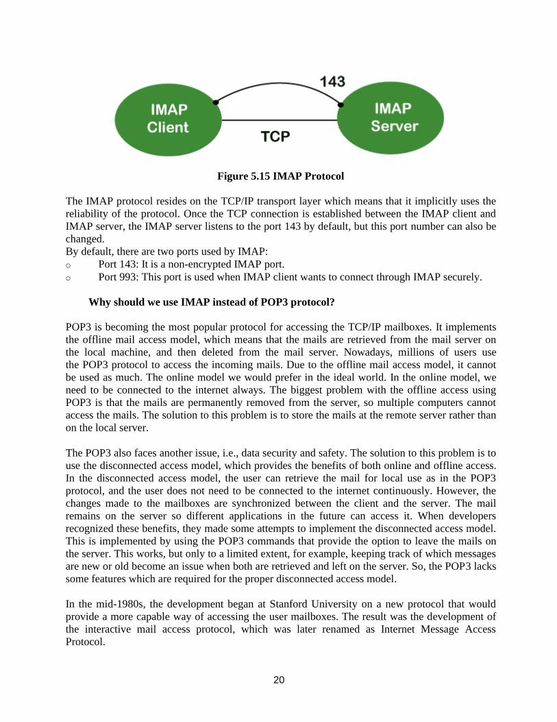
20
Figure 5.15 IMAP Protocol
The IMAP protocol resides on the TCP/IP transport layer which means that it implicitly uses the
reliability of the protocol. Once the TCP connection is established between the IMAP client and
IMAP server, the IMAP server listens to the port 143 by default, but this port number can also be
changed.
By default, there are two ports used by IMAP:
o Port 143: It is a non-encrypted IMAP port.
o Port 993: This port is used when IMAP client wants to connect through IMAP securely.
Why should we use IMAP instead of POP3 protocol?
POP3 is becoming the most popular protocol for accessing the TCP/IP mailboxes. It implements
the offline mail access model, which means that the mails are retrieved from the mail server on
the local machine, and then deleted from the mail server. Nowadays, millions of users use
the POP3 protocol to access the incoming mails. Due to the offline mail access model, it cannot
be used as much. The online model we would prefer in the ideal world. In the online model, we
need to be connected to the internet always. The biggest problem with the offline access using
POP3 is that the mails are permanently removed from the server, so multiple computers cannot
access the mails. The solution to this problem is to store the mails at the remote server rather than
on the local server.
The POP3 also faces another issue, i.e., data security and safety. The solution to this problem is to
use the disconnected access model, which provides the benefits of both online and offline access.
In the disconnected access model, the user can retrieve the mail for local use as in the POP3
protocol, and the user does not need to be connected to the internet continuously. However, the
changes made to the mailboxes are synchronized between the client and the server. The mail
remains on the server so different applications in the future can access it. When developers
recognized these benefits, they made some attempts to implement the disconnected access model.
This is implemented by using the POP3 commands that provide the option to leave the mails on
the server. This works, but only to a limited extent, for example, keeping track of which messages
are new or old become an issue when both are retrieved and left on the server. So, the POP3 lacks
some features which are required for the proper disconnected access model.
In the mid-1980s, the development began at Stanford University on a new protocol that would
provide a more capable way of accessing the user mailboxes. The result was the development of
the interactive mail access protocol, which was later renamed as Internet Message Access
Protocol.
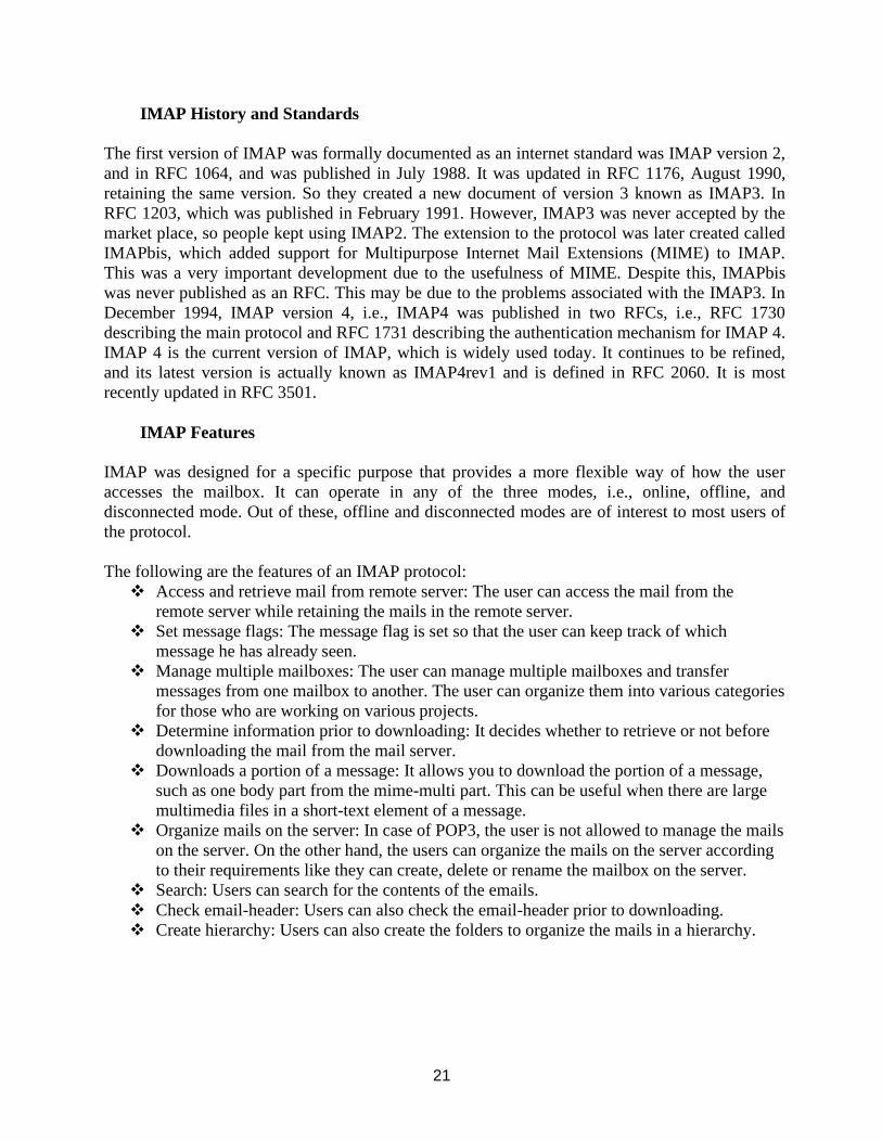
21
IMAP History and Standards
The first version of IMAP was formally documented as an internet standard was IMAP version 2,
and in RFC 1064, and was published in July 1988. It was updated in RFC 1176, August 1990,
retaining the same version. So they created a new document of version 3 known as IMAP3. In
RFC 1203, which was published in February 1991. However, IMAP3 was never accepted by the
market place, so people kept using IMAP2. The extension to the protocol was later created called
IMAPbis, which added support for Multipurpose Internet Mail Extensions (MIME) to IMAP.
This was a very important development due to the usefulness of MIME. Despite this, IMAPbis
was never published as an RFC. This may be due to the problems associated with the IMAP3. In
December 1994, IMAP version 4, i.e., IMAP4 was published in two RFCs, i.e., RFC 1730
describing the main protocol and RFC 1731 describing the authentication mechanism for IMAP 4.
IMAP 4 is the current version of IMAP, which is widely used today. It continues to be refined,
and its latest version is actually known as IMAP4rev1 and is defined in RFC 2060. It is most
recently updated in RFC 3501.
IMAP Features
IMAP was designed for a specific purpose that provides a more flexible way of how the user
accesses the mailbox. It can operate in any of the three modes, i.e., online, offline, and
disconnected mode. Out of these, offline and disconnected modes are of interest to most users of
the protocol.
The following are the features of an IMAP protocol:
❖ Access and retrieve mail from remote server: The user can access the mail from the
remote server while retaining the mails in the remote server.
❖ Set message flags: The message flag is set so that the user can keep track of which
message he has already seen.
❖ Manage multiple mailboxes: The user can manage multiple mailboxes and transfer
messages from one mailbox to another. The user can organize them into various categories
for those who are working on various projects.
❖ Determine information prior to downloading: It decides whether to retrieve or not before
downloading the mail from the mail server.
❖ Downloads a portion of a message: It allows you to download the portion of a message,
such as one body part from the mime-multi part. This can be useful when there are large
multimedia files in a short-text element of a message.
❖ Organize mails on the server: In case of POP3, the user is not allowed to manage the mails
on the server. On the other hand, the users can organize the mails on the server according
to their requirements like they can create, delete or rename the mailbox on the server.
❖ Search: Users can search for the contents of the emails.
❖ Check email-header: Users can also check the email-header prior to downloading.
❖ Create hierarchy: Users can also create the folders to organize the mails in a hierarchy.
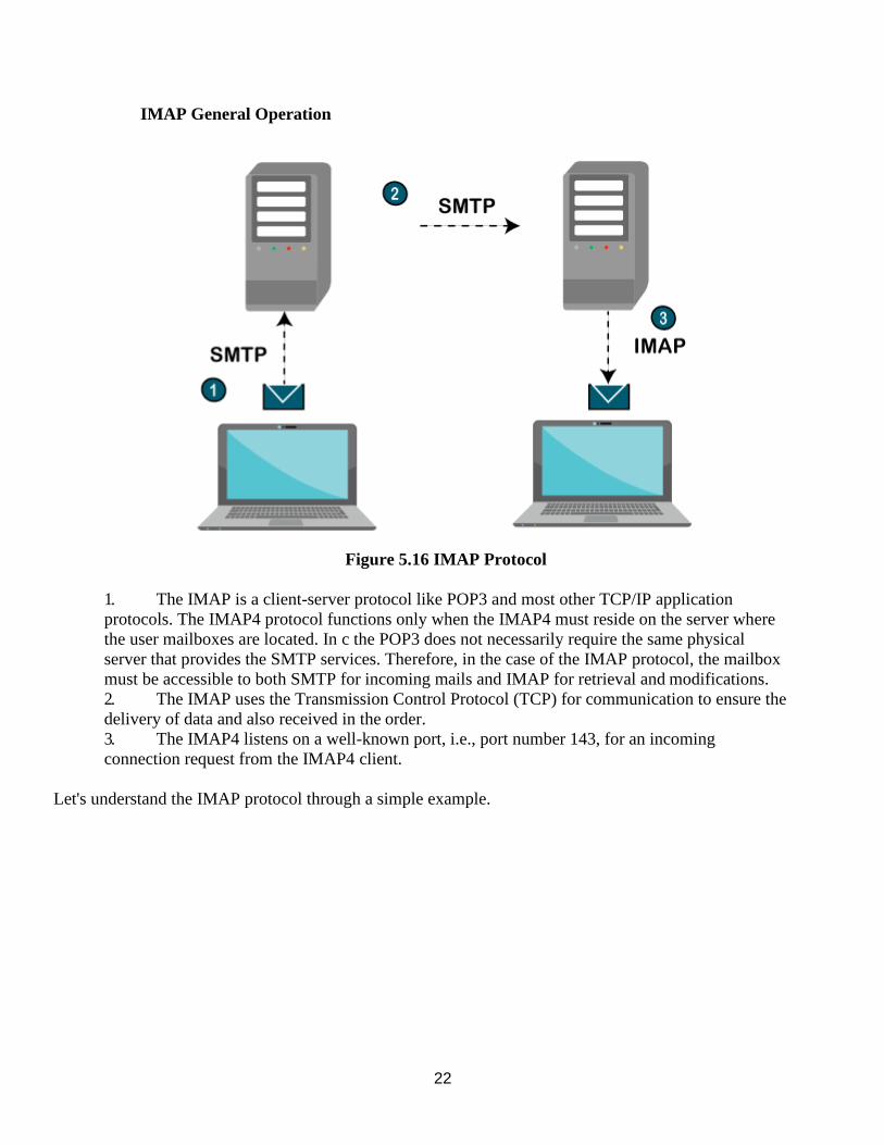
22
IMAP General Operation
Figure 5.16 IMAP Protocol
1. The IMAP is a client-server protocol like POP3 and most other TCP/IP application
protocols. The IMAP4 protocol functions only when the IMAP4 must reside on the server where
the user mailboxes are located. In c the POP3 does not necessarily require the same physical
server that provides the SMTP services. Therefore, in the case of the IMAP protocol, the mailbox
must be accessible to both SMTP for incoming mails and IMAP for retrieval and modifications.
2. The IMAP uses the Transmission Control Protocol (TCP) for communication to ensure the
delivery of data and also received in the order.
3. The IMAP4 listens on a well-known port, i.e., port number 143, for an incoming
connection request from the IMAP4 client.
Let's understand the IMAP protocol through a simple example.
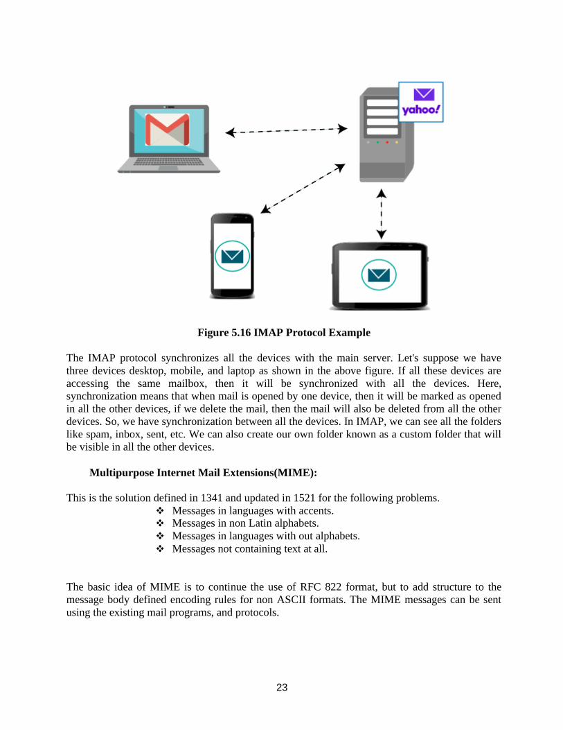
23
Figure 5.16 IMAP Protocol Example
The IMAP protocol synchronizes all the devices with the main server. Let's suppose we have
three devices desktop, mobile, and laptop as shown in the above figure. If all these devices are
accessing the same mailbox, then it will be synchronized with all the devices. Here,
synchronization means that when mail is opened by one device, then it will be marked as opened
in all the other devices, if we delete the mail, then the mail will also be deleted from all the other
devices. So, we have synchronization between all the devices. In IMAP, we can see all the folders
like spam, inbox, sent, etc. We can also create our own folder known as a custom folder that will
be visible in all the other devices.
Multipurpose Internet Mail Extensions(MIME):
This is the solution defined in 1341 and updated in 1521 for the following problems.
❖ Messages in languages with accents. ❖ Messages in non Latin alphabets.
❖ Messages in languages with out alphabets.
❖ Messages not containing text at all.
The basic idea of MIME is to continue the use of RFC 822 format, but to add structure to the
message body defined encoding rules for non ASCII formats. The MIME messages can be sent
using the existing mail programs, and protocols.
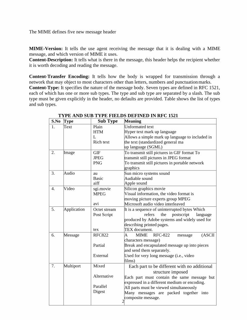
The MIME defines five new message header
MIME-Version: It tells the use agent receiving the message that it is dealing with a MIME
message, and which version of MIME it uses.
Content-Description: It tells what is there in the message, this header helps the recipient whether
it is worth decoding and reading the message.
Content-Transfer Encoding: It tells how the body is wrapped for transmission through a
network that may object to most characters other than letters, numbers and punctuation marks.
Content-Type: It specifies the nature of the message body. Seven types are defined in RFC 1521,
each of which has one or more sub types. The type and sub type are separated by a slash. The sub
type must be given explicitly in the header, no defaults are provided. Table shows the list of types
and sub types.
TYPE AND SUB TYPE FIELDS DEFINED IN RFC 1521
S.No Type Sub Type Meaning
1. Text Plain HTML Rich text
Unformated text Hyper text mark up language
Allows a simple mark up language to included in
the text (standardized general ma up language (SGML)
2. Image GIF
JPEG
PNG
To transmit still pictures in GIF format To
transmit still pictures in JPEG format To transmit still pictures in portable network graphics
3. Audio au
Basic aiff
Sun micro systems sound
Audiable sound Apple sound
4. Video sgi.movie
MPEG
avi
Silicon graphics movie
Visual information, the video format is
moving picture experts group MPEG
Microsoft audio video interleaved
5. Application Octet stream
Post Script
tex
It is a sequence of uninterrupted bytes Which
refers the postscript language
produced by Adobe systems and widely used for
describing printed pages. TEX document.
6. Message RFC822
Partial
External
A MIME RFC-822 message (ASCII characters message)
Break and encapsulated message up into pieces
and send them separately.
Used for very long message (i.e., video
films)
7. Multiport Mixed
Alternative
Parallel
Digest
25
Each part to be different with no additional
structure imposed Each part must contain the same message but
expressed in a different medium or encoding.
All parts must be viewed simultaneously
Many messages are packed together into composite message.
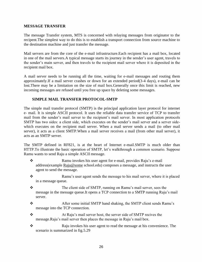
26
MESSAGE TRANSFER
The message Transfer system, MTS is concerned with relaying messages from originator to the
recipent.The simplest way to do this is to establish a transport connection from source machine to
the destination machine and just transfer the message.
Mail servers are from the core of the e-mail infrastructure.Each recipient has a mail box, located
in one of the mail servers.A typical message starts its journey in the sender’s user agent, travels to
the sender’s main server, and then travels to the recipient mail server where it is deposited in the
recipient mail box.
A mail server needs to be running all the time, waiting for e-mail messages and routing them
approximately.If a mail server crashes or down for an extended period(3-4 days), e-mail can be
lost.There may be a limitation on the size of mail box.Generally once this limit is reached, new
incoming messages are refused until you free up space by deleting some messages.
SIMPLE MAIL TRANSFER PROTOCOL-SMTP
The simple mail transfer protocol (SMTP) is the principal application layer protocol for internet
e- mail. It is simple ASCII protocol. It uses the reliable data transfer service of TCP to transfer
mail from the sender’s mail server to the recipient’s mail server. In most application protocols
SMTP has two sides: a client side, which executes on the sender’s mail server and a server side-
which executes on the recipient mail server. When a mail server sends a mail (to other mail
server), it acts as a client SMTP.When a mail server receives a mail (from other mail server), it
acts as an SMTP server.
The SMTP defined in RF821, is at the heart of Internet e-mail.SMTP is much older than
HTTP.To illustrate the basic operation of SMTP, let’s walkthrough a common scenario. Suppose
Ramu wants to send Raju a simple ASCII message.
❖ Ramu invokes his user agent for e-mail, provides Raju’s e-mail
address(example Raju@some school.edu) composes a message, and instructs the user
agent to send the message.
❖ Ramu’s user agent sends the message to his mail server, where it is placed
in a message queue.
❖ The client side of SMTP, running on Ramu’s mail server, sees the
message in the message queue.It opens a TCP connection to a SMTP running Raju’s mail
server.
❖ After some initial SMTP hand shaking, the SMTP client sends Ramu’s
message into the TCP connection.
❖ At Raju’s mail server host, the server side of SMTP recives the
message.Raju’s mail server then places the message in Raju’s mail box.
❖ Raju invokes his user agent to read the message at his convenience. The
scenario is summarized in fig.5.29
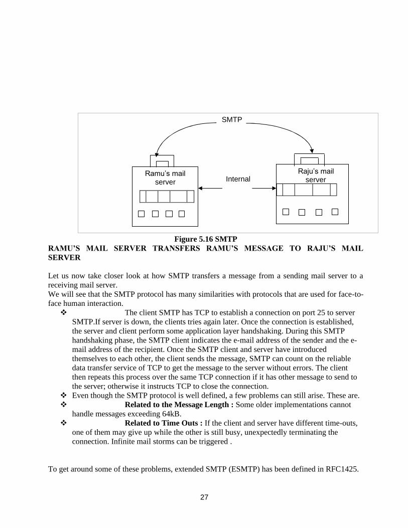
27
SMTP
Internal Raju’s mail
server Ramu’s mail
server
Figure 5.16 SMTP
RAMU’S MAIL SERVER TRANSFERS RAMU’S MESSAGE TO RAJU’S MAIL
SERVER
Let us now take closer look at how SMTP transfers a message from a sending mail server to a
receiving mail server.
We will see that the SMTP protocol has many similarities with protocols that are used for face-to-
face human interaction.
❖ The client SMTP has TCP to establish a connection on port 25 to server
SMTP.If server is down, the clients tries again later. Once the connection is established,
the server and client perform some application layer handshaking. During this SMTP
handshaking phase, the SMTP client indicates the e-mail address of the sender and the e-
mail address of the recipient. Once the SMTP client and server have introduced
themselves to each other, the client sends the message, SMTP can count on the reliable
data transfer service of TCP to get the message to the server without errors. The client
then repeats this process over the same TCP connection if it has other message to send to
the server; otherwise it instructs TCP to close the connection.
❖ Even though the SMTP protocol is well defined, a few problems can still arise. These are.
❖ Related to the Message Length : Some older implementations cannot
handle messages exceeding 64kB.
❖ Related to Time Outs : If the client and server have different time-outs,
one of them may give up while the other is still busy, unexpectedly terminating the
connection. Infinite mail storms can be triggered .
To get around some of these problems, extended SMTP (ESMTP) has been defined in RFC1425.
28
E-mail Gateways: E-mail using SMTP works best when both the sender and receiver on the
internet and can support TCP connections between sender and receiver.However many machines
that are not on the internet)because of security problem) still want to send and recive e- mail from
internet sites.
Another problem occurs when the sender speaks only RFC822 and the receiver speaks only
X.400 or some proprietary vendor specific mail protocol.
Here Host1 speaks only TCP/IP and RFC822, where as host 2 speaks only OSITP4 ans X.400.
They can exchange e-mail using an e-mail gateway.
Procedure:
• Host 1 establishes a TCP connection to gateway and then use SMTP to transfer
message there.
• The gateway then puts the message in a buffer of messages destined to host 2.
• A TP4 connection is established between host 2 and the gateway.
• The message is transferred using OSI equivalent of SMTA.
The problems here are
1) The Internet address and X.400 address are totally different. Need
of elaborating mapping mechanism between them.
2) Envelope and header fields are present in one system and are not
present in the other.
MAIL ACCESS PROTOCOL
Till now we have assumed that an users work on machines that are capable of sending and
receiving e-mail. Sometimes this situation is false. For example in an organization, users work on
desktop PCs that are no in the internet and are capable of sending and receiving e-mail from
outside. Instead the organization has one or more e-mail servers that can send and receive e-mail.
To sned and receive e-mails, a PC must talk to an e-mail server using some kind of delivery
protocol.
There are currently two popular mail access protocols:POP3(Post office Protocol version3 ) and 1
MAP (internet mail access protocol)
TEXT / REFERENCE BOOKS
1. Behrouz A. Fourouzan, “Data Communication and Networking”, McGraw-Hill Education India Pvt. Ltd - New Delhi.
2. William Stallings, Data and Computer Communications (8th ed.), Pearson Education, 2007.
3. P.C. Gupta, Data Communications and Computer Networks, Prentice-Hall of India, 2006.
4. Andrew S. Tanenbaum, “Computer Networks”, Fourth Edition, Pearson.
5. L. L. Peterson and B. S. Davie, Computer Networks: A Systems Approach (3rd ed.), Morgan Kaufmann, 2003.
29
QUESTIONS
PART A
1. Define the two types of user agents in the electronic mail system
2. What is DNS?
3. What is SMTP?
4. State the Purpose of SNMP
5. What is the Domain name system responsible for?
6. What are the four main properties of HTTP?
7. What is SMTP used for?
8. What are the basic functions of email?
9. Define WWW?
10. What is URL?
11. What are the responsibilities of Application Layer
12. Write down the three types of WWW documents.
13. What is Generic Domains
14. What are the two types of connections in FTP?
15. What are the types of messages in HTTP transaction?
16. What are the parts of a browser?
17. How does MIME enhance SMTP?
PART B
1. Explain the functions of SMTP.
2. Write short notes on FTP.
3. Explain about the significance of using HTTP
4. Explain the WWW in detail.
5. Explain about Electronic mail and give brief introduction to POP
6. Explain detail about Domain Name System give details about components and mail servers