Embed Size (px)
Citation preview

WWWVIDYARTHIPLUSCOM
WWWVIDYARTHIPLUSCOM V+ TEAM
ME2403 POWER PLANT ENGINEERING
VII Semester
PREPARED BY
NVKAMALESH
ASSISTANT PROFESSOR
MECHANICAL ENGINEERING DEPARTMENT
SRI ESHWAR COLLEGE OF ENGINEERING
UNIT-I INTRODUCTION TO POWER PLANTS AND BOILERS
STEAM POWER PLANT
A thermal power station is a power plant in which the prime mover is steam driven
Water is heated turns into steam and spins a steam turbine which drives an electrical
generator After it passes through the turbine the steam is condensed in a condenser and
recycled to where it was heated this is known as a Rankine cycle The greatest variation in the
design of thermal power stations is due to the different fuel sources Some prefer to use the
term energy center because such facilities convert forms of heat energy into electricity Some
thermal power plants also deliver heat energy for industrial purposes for district heating or for
desalination of water as well as delivering electrical power A large proportion of CO2 is
produced by the worlds fossil fired thermal power plants efforts to reduce these outputs are
various and widespread
WWWVIDYARTHIPLUSCOM
WWWVIDYARTHIPLUSCOM V+ TEAM
The four main circuits one would come across in any thermal power plant layout are
-Coal andAshCircuit
-AirandGasCircuit
- Feed Water and Steam Circuit
- Cooling Water Circuit
Coal and Ash Circuit
Coal and Ash circuit in a thermal power plant layout mainly takes care of feeding the boiler with
coal from the storage for combustion The ash that is generated during combustion is collected
at the back of the boiler and removed to the ash storage by scrap conveyors The combustion in
the Coal and Ash circuit is controlled by regulating the speed and the quality of coal entering the
grate and the damper openings
Air and Gas Circuit
Air from the atmosphere is directed into the furnace through the air preheated by the action of
a forced draught fan or induced draught fan The dust from the air is removed before it enters
the combustion chamber of the thermal power plant layout The exhaust gases from the
combustion heat the air which goes through a heat exchanger and is finally let off into the
environment
Feed Water and Steam Circuit
The steam produced in the boiler is supplied to the turbines to generate power The steam that
is expelled by the prime mover in the thermal power plant layout is then condensed in a
condenser for re-use in the boiler The condensed water is forced through a pump into the feed
water heaters where it is heated using the steam from different points in the turbine To make
up for the lost steam and water while passing through the various components of the thermal
power plant layout feed water is supplied through external sources Feed water is purified in a
purifying plant to reduce the dissolve salts that could scale the boiler tubes
Cooling Water Circuit
The quantity of cooling water required to cool the steam in a thermal power plant layout is
significantly high and hence it is supplied from a natural water source like a lake or a river After
WWWVIDYARTHIPLUSCOM
WWWVIDYARTHIPLUSCOM V+ TEAM
passing through screens that remove particles that can plug the condenser tubes in a thermal
power plant layout it is passed through the condenser where the steam is condensed The
water is finally discharged back into the water source after cooling Cooling water circuit can
also be a closed system where the cooled water is sent through cooling towers for re-use in the
power plant The cooling water circulation in the condenser of a thermal power plant layout
helps in maintaining a low pressure in the condenser all throughout
All these circuits are integrated to form a thermal power plant layout that generates electricity
to meet our needs
LAYOUT OF HYDEL POWER PLANT
Hydroelectric power plants convert the hydraulic potential energy from water into electrical
energy Such plants are suitable were water with suitable head are available The layout
covered in this article is just a simple one and only cover the important parts of hydroelectric
plantThe different parts of a hydroelectric power plant are
WWWVIDYARTHIPLUSCOM
WWWVIDYARTHIPLUSCOM V+ TEAM
(1) Dam
Dams are structures built over rivers to stop the water flow and form a reservoirThe reservoir
stores the water flowing down the river This water is diverted to turbines in power stations The
dams collect water during the rainy season and stores it thus allowing for a steady flow through
the turbines throughout the year Dams are also used for controlling floods and irrigation The
dams should be water-tight and should be able to withstand the pressure exerted by the water
on it There are different types of dams such as arch dams gravity dams and buttress dams The
height of water in the dam is called head race
(2) Spillway
A spillway as the name suggests could be called as a way for spilling of water from dams It
is used to provide for the release of flood water from a dam It is used to prevent over toping of
the dams which could result in damage or failure of dams Spillways could be controlled type or
uncontrolled type The uncontrolled types start releasing water upon water rising above a
particular level But in case of the controlled type regulation of flow is possible
(3) Penstock and Tunnel
Penstocks are pipes which carry water from the reservoir to the turbines inside power station
They are usually made of steel and are equipped with gate systemsWater under high pressure
flows through the penstock A tunnel serves the same purpose as a penstock It is used when an
obstruction is present between the dam and power station such as a mountain
(4) Surge Tank
Surge tanks are tanks connected to the water conductor system It serves the purpose of
reducing water hammering in pipes which can cause damage to pipes The sudden surges of
water in penstock is taken by the surge tank and when the water requirements increase it
supplies the collected water thereby regulating water flow and pressure inside the penstock
(5) Power Station
Power station contains a turbine coupled to a generator The water brought to the power
station rotates the vanes of the turbine producing torque and rotation of turbine shaft This
WWWVIDYARTHIPLUSCOM
WWWVIDYARTHIPLUSCOM V+ TEAM
rotational torque is transfered to the generator and is converted into electricity The used water
is released through the tail race The difference between head race and tail race is called gross
head and by subtracting the frictional losses we get the net head available to the turbine for
generation of electricity
DIESEL POWER PLANT
Diesel power plants produce power from a diesel engine Diesel electric plants in the range of 2
to 50 MW capacities are used as central stations for small electric supply networks and used as a
standby to hydro electric or thermal plants where continuous power supply is needed Diesel
power plant is not economical compared to other power plants
The diesel power plants are cheaply used in the fields mentioned belowPeak load plants
1 Mobile electric plants
2 Standby units
3 Emergency power plants
4 Starting stations of existing plants
5 Central power station etc
General Layout of Diesel power plants
General Layout of Diesel power plants
WWWVIDYARTHIPLUSCOM
WWWVIDYARTHIPLUSCOM V+ TEAM
Figure shows the arrangements of the engine and its auxiliaries in a diesel power plant
The major components of the plant are
a) Engine
Engine is the heart of a diesel power plant Engine is directly connected through a gear
box to the generator Generally two-stroke engines are used for power generation Now a
days advanced super amp turbo charged high speed engines are available for power
production
b) Air supply system
Air inlet is arranged outside the engine room Air from the atmosphere is filtered by air
filter and conveyed to the inlet manifold of engine In large plants
superchargerturbocharger is used for increasing the pressure of input air which increases
the power output
c) Exhaust System
This includes the silencers and connecting ducts The heat content of the exhaust gas is
utilized in a turbine in a turbocharger to compress the air input to the engine
d) Fuel System
Fuel is stored in a tank from where it flows to the fuel pump through a filter Fuel is
injected to the engine as per the load requirement
e) Cooling system
This system includes water circulating pumps cooling towers water filter etc Cooling
water is circulated through the engine block to keep the temperature of the engine in the
safe range
f) Lubricating system
WWWVIDYARTHIPLUSCOM
WWWVIDYARTHIPLUSCOM V+ TEAM
Lubrication system includes the air pumps oil tanks filters coolers and pipe lines
Lubricant is given to reduce friction of moving parts and reduce the wear and tear of the
engine parts
g) Starting System
There are three commonly used starting systems they are
1) A petrol driven auxiliary engine
2) Use of electric motors
3)Use of compressed air from an air compressor at a pressure of 20 Kgcmrdquo
h) Governing system
The function of a governing system is to maintain the speed of the engine constant
irrespective of load on the plant This is done by varying fuel supply to the engine
according to load
Advantages of diesel power plants
1 More efficient than thermal plant
2 Design Layout etc are simple and cheap
3 Part load efficiency is very high
4 It can be started quickly
5 Simple amp easy maintenance
6 No problem with fuel amp dust handling
7 It can be located in the heart of town
8 Less cooling water required
Disadvantages
1 There is a limitation for size of a diesel engine
2 Life of plant is comparatively less
3 Noise pollution is very high
WWWVIDYARTHIPLUSCOM
WWWVIDYARTHIPLUSCOM V+ TEAM
4 Repair cost is very high
5 High lubrication cost
NUCLEAR POWER PLANT
Nuclear power is the use of sustained Nuclear fission to generate heat and do
useful work Nuclear Electric Plants Nuclear Ships and Submarines use controlled
nuclear energy to heat water and produce steam while in space nuclear energy decays
naturally in a radioisotope thermoelectric generator Scientists are experimenting with
fusion energy for future generation but these experiments do not currently generate
useful energy
Nuclear power provides about 6 of the worlds energy and 13ndash14 of the worlds
electricity with the US France and Japan together accounting for about 50 of nuclear
generated electricity Also more than 150 naval vessels using nuclear propulsion have
been built
Just as many conventional thermal power stations generate electricity by
harnessing the thermal energy released from burning fossil fuels nuclear power plants
convert the energy released from the nucleus of an atom typically via nuclear fission
Nuclear reactor technology
When a relatively large fissile atomic nucleus (usually uranium-235 or
plutonium-239) absorbs a neutron a fission of the atom often results Fission splits the
atom into two or more smaller nuclei with kinetic energy (known as fission products) and
also releases gamma radiation and free neutrons[59] A portion of these neutrons may later
be absorbed by other fissile atoms and create more fissions which release more neutrons
and so on
WWWVIDYARTHIPLUSCOM
WWWVIDYARTHIPLUSCOM V+ TEAM
This nuclear chain reaction can be controlled by using neutron poisons and
neutron moderators to change the portion of neutrons that will go on to cause more
fissions[60] Nuclear reactors generally have automatic and manual systems to shut the
fission reaction down if unsafe conditions are detected
Three nuclear powered ships (top to bottom) nuclear cruisers USS Bainbridge and USS Long
Beach with USS Enterprise the first nuclear powered aircraft carrier in 1964 Crew members are
spelling out Einsteins mass-energy equivalence formula E = mc2 on the flight deck
There are many different reactor designs utilizing different fuels and coolants and
incorporating different control schemes Some of these designs have been engineered to
meet a specific need Reactors for nuclear submarines and large naval ships for example
commonly use highly enriched uranium as a fuel This fuel choice increases the reactors
power density and extends the usable life of the nuclear fuel load but is more expensive
and a greater risk to nuclear proliferation than some of the other nuclear fuels
A number of new designs for nuclear power generation collectively
known as the Generation IV reactors are the subject of active research and may be used
for practical power generation in the future Many of these new designs specifically
attempt to make fission reactors cleaner safer andor less of a risk to the proliferation of
nuclear weapons Passively safe plants (such as the ESBWR) are available to be builtand
other designs that are believed to be nearly fool-proof are being pursued Fusion reactors
which may be viable in the future diminish or eliminate many of the risks associated
with nuclear fission There are trades to be made between safety economic and technical
properties of different reactor designs for particular applications Historically these
decisions were often made in private by scientists regulators and engineers but this may
be considered problematic and since Chernobyl and Three Mile Island many involved
now consider informed consent and morality should be primary considerations
Cooling system
A cooling system removes heat from the reactor core and transports it to
another area of the plant where the thermal energy can be harnessed to produce
WWWVIDYARTHIPLUSCOM
WWWVIDYARTHIPLUSCOM V+ TEAM
electricity or to do other useful work Typically the hot coolant will be used as a heat
source for a boiler and the pressurized steam from that boiler will power one or more
steam turbine driven electrical generators
Flexibility of nuclear power plants
It is often claimed that nuclear stations are inflexible in their output
implying that other forms of energy would be required to meet peak demand While that
is true for the vast majority of reactors this is no longer true of at least some modern
designs Nuclear plants are routinely used in load following mode on a large scale in
France Unit A at the German Biblis Nuclear Power Plant is designed to in- and decrease
his output 15 per minute between 40 and 100 of its nominal power Boiling water
reactors normally have load-following capability implemented by varying the
recirculation water flow
GASS TURBINE POWER PLANT
A gas turbine also called a combustion turbine is a type of internal
combustion engine It has an upstream rotating compressor coupled to a downstream
turbine and a combustion chamber in-between
Energy is added to the gas stream in the combustor where fuel is mixed with
air and ignited In the high pressure environment of the combustor combustion of the
fuel increases the temperature The products of the combustion are forced into the turbine
section There the high velocity and volume of the gas flow is directed through a nozzle
over the turbines blades spinning the turbine which powers the compressor and for
some turbines drives their mechanical output The energy given up to the turbine comes
from the reduction in the temperature and pressure of the exhaust gas
COMBINED POWER CYCLES
In electric power generation a combined cycle is an assembly of heat engines that work
in tandem off the same source of heat converting it into mechanical energy which in
WWWVIDYARTHIPLUSCOM
WWWVIDYARTHIPLUSCOM V+ TEAM
turn usually drives electrical generators The principle is that the exhaust of one heat
engine is used as the heat source for another thus extracting more useful energy from the
heat increasing the systems overall efficiency This works because heat engines are only
able to use a portion of the energy their fuel generates (usually less than 50)
The remaining heat (eg hot exhaust fumes) from combustion is generally wasted
Combining two or more thermodynamic cycles results in improved overall efficiency
reducing fuel costs In stationary power plants a successful common combination is the
Brayton cycle (in the form of a turbine burning natural gas or synthesis gas from coal)
and the Rankine cycle (in the form of a steam power plant) Multiple stage turbine or
steam cylinders are also common
LOAD DURATION CURVE
A load duration curve (LDC) is used in electric power generation to illustrate
the relationship between generating capacity requirements and capacity utilization
A LDC is similar to a load curve but the demand data is ordered in descending
order of magnitude rather than chronologically The LDC curve shows the capacity
utilization requirements for each increment of load The height of each slice is a measure
of capacity and the width of each slice is a measure of the utilization rate or capacity
factor The product of the two is a measure of electrical energy (eg kilowatthours)
HIGH PRESSURE BOILERS
A boiler is a closed vessel in which water or other fluid is heated The heated or
vaporized fluid exits the boiler for use in various processes or heating applications
Most boilers produce steam to be used at saturation temperature that is
saturated steam Superheated steam boilers vaporize the water and then further heat the
steam in a superheater This provides steam at much higher temperature but can
decrease the overall thermal efficiency of the steam generating plant because the higher
steam temperature requires a higher flue gas exhaust temperature There are several ways
WWWVIDYARTHIPLUSCOM
WWWVIDYARTHIPLUSCOM V+ TEAM
to circumvent this problem typically by providing an economizer that heats the feed
water a combustion air heater in the hot flue gas exhaust path or both There are
advantages to superheated steam that may and often will increase overall efficiency of
both steam generation and its utilisation gains in input temperature to a turbine should
outweigh any cost in additional boiler complication and expense There may also be
practical limitations in using wet steam as entrained condensation droplets will damage
turbine blades
Superheated steam presents unique safety concerns because if any system
component fails and allows steam to escape the high pressure and temperature can cause
serious instantaneous harm to anyone in its path Since the escaping steam will initially
be completely superheated vapor detection can be difficult although the intense heat and
sound from such a leak clearly indicates its presence
Superheater operation is similar to that of the coils on an air conditioning unit
although for a different purpose The steam piping is directed through the flue gas path in
the boiler furnace The temperature in this area is typically between 1300ndash1600 degrees
Celsius Some superheaters are radiant type that is they absorb heat by radiation Others
are convection type absorbing heat from a fluid Some are a combination of the two
types Through either method the extreme heat in the flue gas path will also heat the
superheater steam piping and the steam within While the temperature of the steam in the
superheater rises the pressure of the steam does not the turbine or moving pistons offer a
continuously expanding space and the pressure remains the same as that of the boiler
Almost all steam superheater system designs remove droplets entrained in the steam to
prevent damage to the turbine blading and associated piping
SUPERCRITICAL BOILER
Supercritical steam generators (also known as Benson boilers) are frequently
used for the production of electric power They operate at supercritical pressure In
contrast to a subcritical boiler a supercritical steam generator operates at such a high
pressure (over 3200 psi2206 MPa or 2206 bar) that actual boiling ceases to occur and
WWWVIDYARTHIPLUSCOM
WWWVIDYARTHIPLUSCOM V+ TEAM
the boiler has no water - steam separation There is no generation of steam bubbles within
the water because the pressure is above the critical pressure at which steam bubbles
can form It passes below the critical point as it does work in the high pressure turbine
and enters the generators condenser This is more efficient resulting in slightly less fuel
use The term boiler should not be used for a supercritical pressure steam generator as
no boiling actually occurs in this device
FLUIDIZED BED BOILERS
The major portion of the coal available in India is of low quality high ash content
and low calorific value The traditional grate fuel firing systems have got limitations and
are techno-economically unviable to meet the challenges of future Fluidized bed
combustion has emerged as a viable alternative and has significant advantages over
conventional firing system and offers multiple benefits ndash compact boiler design fuel
flexibility higher combustion efficiency and reduced emission of noxious pollutants such
as SOx and NOx The fuels burnt in these boilers include coal washery rejects rice husk
bagasse amp other agricultural wastes The fluidized bed boilers have a wide capacity
range- 05 Thr to over 100 Thr
UNIT-II STEAM POWER PLANT
Coal needs to be stored at various stages of the preparation process and
conveyed around the CPP facilities Coal handling is part of the larger field of bulk
material handling and is a complex and vital part of the CPP
Stockpiles
Stockpiles provide surge capacity to various parts of the CPP ROM coal is
delivered with large variations in production rate of tonnes per hour (tph) A ROM
stockpile is used to allow the washplant to be fed coal at lower constant rate A
simple stockpile is formed by machinery dumping coal into a pile either from dump
trucks pushed into heaps with bulldozers or from conveyor booms More controlled
stockpiles are formed using stackers to form piles along the length of a conveyor and
WWWVIDYARTHIPLUSCOM
WWWVIDYARTHIPLUSCOM V+ TEAM
reclaimers to retrieve the coal when required for product loading etc Taller and
wider stockpiles reduce the land area required to store a set tonnage of coal Larger coal
stockpiles have a reduced rate of heat lost leading to a higher risk of spontaneous
combustion
Stacking
Travelling lugging boom stackers that straddle a feed conveyor are commonly used
to create coal stockpiles
Reclaiming
Tunnel conveyors can be fed by a continuous slot hopper or bunker beneath the
stockpile to reclaim material Front-end loaders and bulldozers can be used to push the
coal into feeders Sometimes front-end loaders are the only means of reclaiming coal
from the stockpile This has a low up-front capital cost but much higher operating costs
measured in dollars per tonne handled High-capacity stockpiles are commonly reclaimed
using bucket-wheel reclaimers These can achieve very high rates
ASH HANDLING SYSTEMS
Ash Handling Systems is the none un combusted portion or residue after taking
combustion of any solid fuel
Solid fuel is usually coal And any coal contains some non combustible portion which is
called ash Content of that coal
There are different types of ashes
bull Bottom ash
bull fly ash
WWWVIDYARTHIPLUSCOM
WWWVIDYARTHIPLUSCOM V+ TEAM
Bottom ash is the residue which remains in the solid form at the bottom and fly ash is the
light particle which goes out along with exhaust gases and usually they are collected in
chimneys
Taking their so formed ash away from the Plant Boiler is called ndash ASH HANDLING
SYSTEM This is done in either
bull Mechanical conveying
bull Pneumatic conveying
Mechanical system requires conveyors and Pneumatic system requires ndash compressed air
to carry out the ash
Ash Handling Systems
Bulk Material Handling Systems
Conveyors And Material Handling Equipments
Process Equipments And Storage Equipments
Portable Handling Equipments
Rotary Equipments
Pneumatic Conveying Systems
Magnetic Equipments
Vibratory Equipments
Spares
Overhead Bag Handling Systems
COMBUSTION EQUIPMENTS
Combustion control options range from electro mechanical through to full
microprocessor control systems to match both application and customer needs
Cochran supply an extensive range of fuel handling equipment to complement and
help ensure that the optimum performance from the combustion and control
equipment is maintained Fuel handling equipment includes gas boosters oil
WWWVIDYARTHIPLUSCOM
WWWVIDYARTHIPLUSCOM V+ TEAM
pumping and heating stations fuel metering and instrumentation packages are
available to match individual installation requirements
STOCKERS
A mechanical stoker is a device which feeds coal into the firebox of a boiler It is
standard equipment on large stationary boilers and was also fitted to large steam
locomotives to ease the burden of the fireman The locomotive type has a screw
conveyor (driven by an auxiliary steam engine) which feeds the coal into the
firebox The coal is then distributed across the grate by steam jets controlled by the
fireman Power stations usually use pulverized coal-fired boilers
PULVERISER
A pulverizer or grinder is a mechanical device for the grinding of many different
types of materials For example they are used to pulverize coal for combustion in
the steam-generating furnaces of fossil fuel power plants
Types of pulverizers
Ball and tube mills
A ball mill is a pulverizer that consists of a horizontal rotating cylinder up to three
diameters in length containing a charge of tumbling or cascading steel balls
pebbles or rods
A tube mill is a revolving cylinder of up to five diameters in length used for fine
pulverization of ore rock and other such materials the material mixed with water
is fed into the chamber from one end and passes out the other end as slime (slurry)
Ring and ball mill
This type of mill consists of two rings separated by a series of large balls The
lower ring rotates while the upper ring presses down on the balls via a set of spring
and adjuster assemblies The material to be pulverized is introduced into the center
WWWVIDYARTHIPLUSCOM
WWWVIDYARTHIPLUSCOM V+ TEAM
or side of the pulverizer (depending on the design) and is ground as the lower ring
rotates causing the balls to orbit between the upper and lower rings The pulverized
material is carried out of the mill by the flow of air moving through it The size of
the pulverized particles released from the grinding section of the mill is determined
by a classifer separator
Vertical roller mill
Similar to the ring and ball mill this mill uses large tires to crush the coal These
are usually found in utility plants
Raw coal is gravity-fed through a central feed pipe to the grinding table where it
flows outwardly by centrifugal action and is ground between the rollers and table
Hot primary air for drying and coal transport enters the windbox plenum
underneath the grinding table and flows upward through a swirl ring having
multiple sloped nozzles surrounding the grinding table The air mixes with and
dries coal in the grinding zone and carries pulverized coal particles upward into a
classifier
Fine pulverized coal exits the outlet section through multiple discharge coal pipes
leading to the burners while oversized coal particles are rejected and returned to
the grinding zone for further grinding Pyrites and extraneous dense impurity
material fall through the nozzle ring and are plowed by scraper blades attached to
the grinding table into the pyrites chamber to be removed Mechanically the
vertical roller mill is categorized as an applied force mill There are three grinding
roller wheel assemblies in the mill grinding section which are mounted on a
loading frame via pivot point The fixed-axis roller in each roller wheel assembly
rotates on a segmentally-lined grinding table that is supported and driven by a
planetary gear reducer direct-coupled to a motor The grinding force for coal
pulverization is applied by a loading frame This frame is connected by vertical
tension rods to three hydraulic cylinders secured to the mill foundation All forces
used in the pulverizing process are transmitted to the foundation via the gear
WWWVIDYARTHIPLUSCOM
WWWVIDYARTHIPLUSCOM V+ TEAM
reducer and loading elements The pendulum movement of the roller wheels
provides a freedom for wheels to move in a radial direction which results in no
radial loading against the mill housing during the pulverizing process
Depending on the required coal fineness there are two types of classifier that may
be selected for a vertical roller mill The dynamic classifier which consists of a
stationary angled inlet vane assembly surrounding a rotating vane assembly or
cage is capable of producing micron fine pulverized coal with a narrow particle
size distribution In addition adjusting the speed of the rotating cage can easily
change the intensity of the centrifugal force field in the classification zone to
achieve coal fineness control real-time to make immediate accommodation for a
change in fuel or boiler load conditions For the applications where a micron fine
pulverized coal is not necessary the static classifier which consists of a cone
equipped with adjustable vanes is an option at a lower cost since it contains no
moving parts With adequate mill grinding capacity a vertical mill equipped with a
static classifier is capable of producing a coal fineness up to 995 or higher lt50
mesh and 80 or higher lt200 mesh while one equipped with a dynamic classifier
produces coal fineness levels of 100 lt100 mesh and 95 lt200 mesh or better
Bowl mill
Similar to the vertical roller mill it also uses tires to crush coal There are two
types a deep bowl mill and a shallow bowl mill
Demolition pulverizer
An attachment fitted to an excavator Commonly used in demolition work to break
up large pieces of concrete
ELECTROSTATIC PRECIPITATOR
An electrostatic precipitator (ESP) or electrostatic air cleaner is a particulate
collection device that removes particles from a flowing gas (such as air) using the
WWWVIDYARTHIPLUSCOM
WWWVIDYARTHIPLUSCOM V+ TEAM
force of an induced electrostatic charge Electrostatic precipitators are highly
efficient filtration devices that minimally impede the flow of gases through the
device and can easily remove fine particulate matter such as dust and smoke from
the air stream[1] In contrast to wet scrubbers which apply energy directly to the
flowing fluid medium an ESP applies energy only to the particulate matter being
collected and therefore is very efficient in its consumption of energy (in the form of
electricity)
Modern industrial electrostatic precipitators
ESPs continue to be excellent devices for control of many industrial particulate
emissions including smoke from electricity-generating utilities (coal and oil fired)
salt cake collection from black liquor boilers in pulp mills and catalyst collection
from fluidized bed catalytic cracker units in oil refineries to name a few These
devices treat gas volumes from several hundred thousand ACFM to 25 million
ACFM (1180 msup3s) in the largest coal-fired boiler applications For a coal-fired
boiler the collection is usually performed downstream of the air preheater at about
160 degC (320 degF) which provides optimal resistivity of the coal-ash particles For
some difficult applications with low-sulfur fuel hot-end units have been built
operating above 371 degC (700 degF)
The original parallel platendashweighted wire design (described above) has evolved as
more efficient (and robust) discharge electrode designs were developed today
focusing on rigid (pipe-frame) discharge electrodes to which many sharpened
spikes are attached (barbed wire) maximizing corona production Transformer-
rectifier systems apply voltages of 50 ndash 100 kV at relatively high current densities
Modern controls such as an automatic voltage control minimize electric sparking
and prevent arcing (sparks are quenched within 12 cycle of the TR set) avoiding
damage to the components Automatic plate-rapping systems and hopper-
evacuation systems remove the collected particulate matter while on line
theoretically allowing ESPs to stay in operation for years at a time
WWWVIDYARTHIPLUSCOM
WWWVIDYARTHIPLUSCOM V+ TEAM
Wet electrostatic precipitator
A wet electrostatic precipitator (WESP or wet ESP) operates with saturated air
streams (100 relative humidity) WESPs are commonly used to remove liquid
droplets such as sulfuric acid mist from industrial process gas streams The WESP
is also commonly used where the gases are high in moisture content contain
combustible particulate have particles that are sticky in nature
The preferred and most modern type of WESP is a downflow tubular design This
design allows the collected moisture and particulate to form a slurry that helps to
keep the collection surfaces clean
Plate style and upflow design WESPs are very unreliable and should not be used in
applications where particulate is sticky in nature
Consumer-oriented electrostatic air cleaners
Plate precipitators are commonly marketed to the public as air purifier devices or as
a permanent replacement for furnace filters but all have the undesirable attribute of
being somewhat messy to clean A negative side-effect of electrostatic precipitation
devices is the production of toxic ozone and NOx However electrostatic
precipitators offer benefits over other air purifications technologies such as HEPA
filtration which require expensive filters and can become production sinks for
many harmful forms of bacteria
The two-stage design (charging section ahead of collecting section) has the benefit
of minimizing ozone production which would adversely affect health of personnel
working in enclosed spaces For shipboard engine rooms where gearboxes generate
an oil fog two-stage ESPs are used to clean the air improving the operating
environment and preventing buildup of flammable oil fog accumulations Collected
oil is returned to the gear lubricating system
WWWVIDYARTHIPLUSCOM
WWWVIDYARTHIPLUSCOM V+ TEAM
With electrostatic precipitators if the collection plates are allowed to accumulate
large amounts of particulate matter the particles can sometimes bond so tightly to
the metal plates that vigorous washing and scrubbing may be required to
completely clean the collection plates The close spacing of the plates can make
thorough cleaning difficult and the stack of plates often cannot be easily
disassembled for cleaning One solution suggested by several manufacturers is to
wash the collector plates in a dishwasher
Some consumer precipitation filters are sold with special soak-off cleaners where
the entire plate array is removed from the precipitator and soaked in a large
container overnight to help loosen the tightly bonded particulates
A study by the Canada Mortgage and Housing Corporation testing a variety of
forced-air furnace filters found that ESP filters provided the best and most cost-
effective means of cleaning air using a forced-air system
DRAUGHT
Most boilers now depend on mechanical draught equipment rather than natural
draught This is because natural draught is subject to outside air conditions and
temperature of flue gases leaving the furnace as well as the chimney height All
these factors make proper draught hard to attain and therefore make mechanical
draught equipment much more economical
There are three types of mechanical draught
Induced draught This is obtained one of three ways the first being the stack effect of a
heated chimney in which the flue gas is less dense than the ambient air surrounding the
boiler The denser column of ambient air forces combustion air into and through the
boiler The second method is through use of a steam jet The steam jet oriented in the
direction of flue gas flow induces flue gasses into the stack and allows for a greater flue
gas velocity increasing the overall draught in the furnace This method was common on
steam driven locomotives which could not have tall chimneys The third method is by
WWWVIDYARTHIPLUSCOM
WWWVIDYARTHIPLUSCOM V+ TEAM
simply using an induced draught fan (ID fan) which removes flue gases from the furnace
and forces the exhaust gas up the stack Almost all induced draught furnaces operate with
a slightly negative pressure
Forced draught Draught is obtained by forcing air into the furnace by means of a fan (FD
fan) and ductwork Air is often passed through an air heater which as the name suggests
heats the air going into the furnace in order to increase the overall efficiency of the boiler
Dampers are used to control the quantity of air admitted to the furnace Forced draught
furnaces usually have a positive pressure
Balanced draught Balanced draught is obtained through use of both induced and forced
draught This is more common with larger boilers where the flue gases have to travel a
long distance through many boiler passes The induced draught fan works in conjunction
with the forced draught fan allowing the furnace pressure to be maintained slightly below
atmospheric
SURFACE CONDERSER
Surface condenser is the commonly used term for a water-cooled shell and tube
heat exchanger installed on the exhaust steam from a steam turbine in thermal
power stations These condensers are heat exchangers which convert steam from its
gaseous to its liquid state at a pressure below atmospheric pressure Where cooling
water is in short supply an air-cooled condenser is often used An air-cooled
condenser is however significantly more expensive and cannot achieve as low a
steam turbine exhaust pressure as a water cooled surface condenser
Surface condensers are also used in applications and industries other than the
condensing of steam turbine exhaust in power plants
In thermal power plants the primary purpose of a surface condenser is to condense
the exhaust steam from a steam turbine to obtain maximum efficiency and also to
convert the turbine exhaust steam into pure water (referred to as steam condensate)
so that it may be reused in the steam generator or boiler as boiler feed water
WWWVIDYARTHIPLUSCOM
WWWVIDYARTHIPLUSCOM V+ TEAM
The steam turbine itself is a device to convert the heat in steam to mechanical
power The difference between the heat of steam per unit weight at the inlet to the
turbine and the heat of steam per unit weight at the outlet to the turbine represents
the heat which is converted to mechanical power Therefore the more the
conversion of heat per pound or kilogram of steam to mechanical power in the
turbine the better is its efficiency By condensing the exhaust steam of a turbine at
a pressure below atmospheric pressure the steam pressure drop between the inlet
and exhaust of the turbine is increased which increases the amount of heat
available for conversion to mechanical power Most of the heat liberated due to
condensation of the exhaust steam is carried away by the cooling medium (water or
air) used by the surface condenser
COOLING TOWERS
Cooling towers are heat removal devices used to transfer process waste heat to the
atmosphere Cooling towers may either use the evaporation of water to remove
process heat and cool the working fluid to near the wet-bulb air temperature or in
the case of Close Circuit Dry Cooling Towers rely solely on air to cool the
working fluid to near the dry-bulb air temperature Common applications include
cooling the circulating water used in oil refineries chemical plants power stations
and building cooling The towers vary in size from small roof-top units to very
large hyperboloid structures that can be up to 200 metres tall and 100 metres in
diameter or rectangular structures that can be over 40 metres tall and 80 metres
long Smaller towers are normally factory-built while larger ones are constructed
on site They are often associated with nuclear power plants in popular culture
although cooling towers are constructed on many types of buildings
Industrial cooling towers
Industrial cooling towers can be used to remove heat from various sources such as
machinery or heated process material The primary use of large industrial cooling
towers is to remove the heat absorbed in the circulating cooling water systems used
WWWVIDYARTHIPLUSCOM
WWWVIDYARTHIPLUSCOM V+ TEAM
in power plants petroleum refineries petrochemical plants natural gas processing
plants food processing plants semi-conductor plants and for other industrial
facilities such as in condensers of distillation columns for cooling liquid in
crystallization etc[2] The circulation rate of cooling water in a typical 700 MW
coal-fired power plant with a cooling tower amounts to about 71600 cubic metres
an hour (315000 US gallons per minute)[3] and the circulating water requires a
supply water make-up rate of perhaps 5 percent (ie 3600 cubic metres an hour)
If that same plant had no cooling tower and used once-through cooling water it
would require about 100000 cubic metres an hour [4] and that amount of water
would have to be continuously returned to the ocean lake or river from which it
was obtained and continuously re-supplied to the plant Furthermore discharging
large amounts of hot water may raise the temperature of the receiving river or lake
to an unacceptable level for the local ecosystem Elevated water temperatures can
kill fish and other aquatic organisms (See thermal pollution) A cooling tower
serves to dissipate the heat into the atmosphere instead and wind and air diffusion
spreads the heat over a much larger area than hot water can distribute heat in a body
of water Some coal-fired and nuclear power plants located in coastal areas do
make use of once-through ocean water But even there the offshore discharge
water outlet requires very careful design to avoid environmental problems
Petroleum refineries also have very large cooling tower systems A typical large
refinery processing 40000 metric tonnes of crude oil per day (300000 barrels
(48000 m3) per day) circulates about 80000 cubic metres of water per hour
through its cooling tower system
The worlds tallest cooling tower is the 200 metre tall cooling tower of
Niederaussem Power Station
Heat transfer methods
With respect to the heat transfer mechanism employed the main types are
WWWVIDYARTHIPLUSCOM
WWWVIDYARTHIPLUSCOM V+ TEAM
Wet cooling towers or simply open circuit cooling towers operate on the principle of
evaporation The working fluid and the evaporated fluid (usually H2O) are one and the
same
Dry Cooling Towers operate by heat transfer through a surface that separates the working
fluid from ambient air such as in a tube to air heat exchanger utilizing convective heat
transfer They do not use evaporation
Fluid coolers or Closed Circuit Cooling Towers are hybrids that pass the working fluid
through a tube bundle upon which clean water is sprayed and a fan-induced draft
applied The resulting heat transfer performance is much closer to that of a wet cooling
tower with the advantage provided by a dry cooler of protecting the working fluid from
environmental exposure and contamination
In a wet cooling tower (or Open Circuit Cooling Tower) the warm water can be
cooled to a temperature lower than the ambient air dry-bulb temperature if the air
is relatively dry (see dew point and psychrometrics) As ambient air is drawn past
a flow of water an small portion of the water evaporate the energy required by that
portion of the water to evaporate is taken from the remaining mass of water
reducing his temperature (aproximately by 970 BTU for each pound of evaporated
water) Evaporation results in saturated air conditions lowering the temperature of
the water process by the tower to a value close to wet bulb air temperature which is
lower than the ambient dry bulb air temperature the difference determined by the
humidity of the ambient air
To achieve better performance (more cooling) a medium called fill is used to
increase the surface area and the time of contact between the air and water flows
Splash fill consists of material placed to interrupt the water flow causing splashing
Film fill is composed of thin sheets of material (usually PVC) upon which the water
flows Both methods create increased surface area and time of contact between the
fluid (water) and the gas (air)
Air flow generation methods
WWWVIDYARTHIPLUSCOM
WWWVIDYARTHIPLUSCOM V+ TEAM
With respect to drawing air through the tower there are three types of cooling
towers
Natural draft which utilizes buoyancy via a tall chimney Warm moist air naturally rises
due to the density differential to the dry cooler outside air Warm moist air is less dense
than drier air at the same pressure This moist air buoyancy produces a current of air
through the tower
Mechanical draft which uses power driven fan motors to force or draw air through the
tower
Induced draft A mechanical draft tower with a fan at the discharge which pulls air
through tower The fan induces hot moist air out the discharge This produces low
entering and high exiting air velocities reducing the possibility of recirculation in which
discharged air flows back into the air intake This fanfin arrangement is also known as
draw-through (see Image 2 3)
Forced draft A mechanical draft tower with a blower type fan at the intake The fan
forces air into the tower creating high entering and low exiting air velocities The low
exiting velocity is much more susceptible to recirculation With the fan on the air intake
the fan is more susceptible to complications due to freezing conditions Another
disadvantage is that a forced draft design typically requires more motor horsepower than
an equivalent induced draft design The forced draft benefit is its ability to work with high
static pressure They can be installed in more confined spaces and even in some indoor
situations This fanfill geometry is also known as blow-through (see Image 4)
Fan assisted natural draft A hybrid type that appears like a natural draft though airflow is
assisted by a fan
Hyperboloid (aka hyperbolic) cooling towers (Image 1) have become the design
standard for all natural-draft cooling towers because of their structural strength and
minimum usage of material The hyperboloid shape also aids in accelerating the
upward convective air flow improving cooling efficiency They are popularly
associated with nuclear power plants However this association is misleading as
WWWVIDYARTHIPLUSCOM
WWWVIDYARTHIPLUSCOM V+ TEAM
the same kind of cooling towers are often used at large coal-fired power plants as
well Similarly not all nuclear power plants have cooling towers instead cooling
their heat exchangers with lake river or ocean water
Categorization by air-to-water flow
Crossflow
Crossflow is a design in which the air flow is directed perpendicular to the water
flow (see diagram below) Air flow enters one or more vertical faces of the cooling
tower to meet the fill material Water flows (perpendicular to the air) through the
fill by gravity The air continues through the fill and thus past the water flow into
an open plenum area A distribution or hot water basin consisting of a deep pan
with holes or nozzles in the bottom is utilized in a crossflow tower Gravity
distributes the water through the nozzles uniformly across the fill material
Counterflow
In a counterflow design the air flow is directly opposite to the water flow (see
diagram below) Air flow first enters an open area beneath the fill media and is then
drawn up vertically The water is sprayed through pressurized nozzles and flows
downward through the fill opposite to the air flow
Common to both designs
The interaction of the air and water flow allow a partial equalization and evaporation of
water
The air now saturated with water vapor is discharged from the cooling tower
WWWVIDYARTHIPLUSCOM
WWWVIDYARTHIPLUSCOM V+ TEAM
A collection or cold water basin is used to contain the water after its interaction with the
air flow
Both crossflow and counterflow designs can be used in natural draft and
mechanical draft cooling towers
UNIT-III NUCLEAR AND HYDEL POWER PLANT
NUCLEAR ENERGY
Nuclear Energy is the use of sustained Nuclear fission to generate heat and
do useful work Nuclear Electric Plants Nuclear Ships and Submarines use
controlled nuclear energy to heat water and produce steam while in space nuclear
energy decays naturally in a radioisotope thermoelectric generator Scientists are
experimenting with fusion energy for future generation but these experiments do
not currently generate useful energy
Nuclear power provides about 6 of the worlds energy and 13ndash14 of the
worlds electricity with the US France and Japan together accounting for about
50 of nuclear generated electricity Also more than 150 naval vessels using
nuclear propulsion have been built
Nuclear power is controversial and there is an ongoing debate about the use
of nuclear energy Proponents such as the World Nuclear Association and IAEA
contend that nuclear power is a sustainable energy source that reduces carbon
emissions Opponents such as Greenpeace International and NIRS believe that
nuclear power poses many threats to people and the environment
WWWVIDYARTHIPLUSCOM
WWWVIDYARTHIPLUSCOM V+ TEAM
Some serious nuclear and radiation accidents have occurred Nuclear power plant
accidents include the Chernobyl disaster (1986) Fukushima I nuclear accidents
(2011) and the Three Mile Island accident (1979)[10] Nuclear-powered submarine
mishaps include the K-19 reactor accident (1961) the K-27 reactor accident (1968)
and the K-431 reactor accident (1985) International research is continuing into
safety improvements such as passively safe plants and the possible future use of
nuclear fusion
NUCLEAR FISSION
In nuclear physics and nuclear chemistry nuclear fission is a nuclear
reaction in which the nucleus of an atom splits into smaller parts (lighter nuclei)
often producing free neutrons and photons (in the form of gamma rays) The two
nuclei produced are most often of comparable size typically with a mass ratio
around 32 for common fissile isotopes[1][2] Most fissions are binary fissions but
occasionally (2 to 4 times per 1000 events) three positively-charged fragments are
produced in a ternary fission The smallest of these ranges in size from a proton to
an argon nucleus
Fission is usually an energetic nuclear reaction induced by a neutron
although it is occasionally seen as a form of spontaneous radioactive decay
especially in very high-mass-number isotopes The unpredictable composition of
the products (which vary in a broad probabilistic and somewhat chaotic manner)
distinguishes fission from purely quantum-tunnelling processes such as proton
emission alpha decay and cluster decay which give the same products every time
Fission of heavy elements is an exothermic reaction which can release
large amounts of energy both as electromagnetic radiation and as kinetic energy of
the fragments (heating the bulk material where fission takes place) In order for
WWWVIDYARTHIPLUSCOM
WWWVIDYARTHIPLUSCOM V+ TEAM
fission to produce energy the total binding energy of the resulting elements must
be less than that of the starting element Fission is a form of nuclear transmutation
because the resulting fragments are not the same element as the original atom
NUCLEAR FUSION
In nuclear physics nuclear chemistry and astrophysics nuclear fusion is
the process by which two or more atomic nuclei join together or fuse to form a
single heavier nucleus This is usually accompanied by the release or absorption of
large quantities of energy Large-scale thermonuclear fusion processes involving
many nuclei fusing at once must occur in matter at very high densities and
temperatures
The fusion of two nuclei with lower masses than iron (which along with
nickel has the largest binding energy per nucleon) generally releases energy while
the fusion of nuclei heavier than iron absorbs energy The opposite is true for the
reverse process nuclear fission
In the simplest case of hydrogen fusion two protons must be brought close
enough for the weak nuclear force to convert either of the identical protons into a
neutron thus forming the hydrogen isotope deuterium In more complex cases of
heavy ion fusion involving two or more nucleons the reaction mechanism is
different but the same result occursmdash smaller nuclei are combined into larger
nuclei
Nuclear fusion occurs naturally in all active stars Synthetic fusion as a
result of human actions has also been achieved although this has not yet been
completely controlled as a source of nuclear power (see fusion power) In the
laboratory successful nuclear physics experiments have been carried out that
involve the fusion of many different varieties of nuclei but the energy output has
been negligible in these studies In fact the amount of energy put into the process
has always exceeded the energy output
WWWVIDYARTHIPLUSCOM
WWWVIDYARTHIPLUSCOM V+ TEAM
Uncontrolled nuclear fusion has been carried out many times in nuclear
weapons testing which results in a deliberate explosion These explosions have
always used the heavy isotopes of hydrogen deuterium (H-2) and tritium (H-3)
and never the much more common isotope of hydrogen (H-1) sometimes called
protium
Building upon the nuclear transmutation experiments by Ernest Rutherford
carried out several years earlier the fusion of the light nuclei (hydrogen isotopes)
was first accomplished by Mark Oliphant in 1932 Then the steps of the main cycle
of nuclear fusion in stars were first worked out by Hans Bethe throughout the
remainder of that decade
Research into fusion for military purposes began in the early 1940s as part
of the Manhattan Project but this was not accomplished until 1951 (see the
Greenhouse Item nuclear test) and nuclear fusion on a large scale in an explosion
was first carried out on November 1 1952 in the Ivy Mike hydrogen bomb test
Research into developing controlled thermonuclear fusion for civil purposes also
began in the 1950s and it continues to this day
TYPES OF REACTORS
Pressurized water reactors (PWRs) constitute a majority of all western nuclear
power plants and are one of two types of light water reactor (LWR) the other type
being boiling water reactors (BWRs) In a PWR the primary coolant (water) is
pumped under high pressure to the reactor core where it is heated by the energy
generated by the fission of atoms The heated water then flows to a steam generator
where it transfers its thermal energy to a secondary system where steam is
generated and flows to turbines which in turn spins an electric generator In
contrast to a boiling water reactor pressure in the primary coolant loop prevents the
water from boiling within the reactor All LWRs use ordinary light water as both
coolant and neutron moderator
WWWVIDYARTHIPLUSCOM
WWWVIDYARTHIPLUSCOM V+ TEAM
PWRs were originally designed to serve as nuclear propulsion for nuclear
submarines and were used in the original design of the second commercial power
plant at Shippingport Atomic Power Station
PWRs currently operating in the United States are considered Generation II
reactors Russias VVER reactors are similar to US PWRs France operates many
PWRs to generate the bulk of their electricity
Several hundred PWRs are used for marine propulsion in aircraft carriers nuclear
submarines and ice breakers In the US they were originally designed at the Oak
Ridge National Laboratory for use as a nuclear submarine power plant Follow-on
work was conducted by Westinghouse Bettis Atomic Power Laboratory[1] The first
commercial nuclear power plant at Shippingport Atomic Power Station was
originally designed as a pressurized water reactor on insistence from Admiral
Hyman G Rickover that a viable commercial plant would include none of the
crazy thermodynamic cycles that everyone else wants to build
The US Army Nuclear Power Program operated pressurized water reactors from
1954 to 1974
Three Mile Island Nuclear Generating Station initially operated two pressurized
water reactor plants TMI-1 and TMI-2 The partial meltdown of TMI-2 in 1979
essentially ended the growth in new construction nuclear power plants in the
United States
Design
WWWVIDYARTHIPLUSCOM
WWWVIDYARTHIPLUSCOM V+ TEAM
Pictorial explanation of power transfer in a pressurized water reactor Primary coolant is
in orange and the secondary coolant (steam and later feedwater) is in blue
Nuclear fuel in the reactor vessel is engaged in a fission chain reaction which
produces heat heating the water in the primary coolant loop by thermal conduction
through the fuel cladding The hot primary coolant is pumped into a heat exchanger
called the steam generator where it flows through hundreds or thousands of tubes
(usually 34 inch in diameter) Heat is transferred through the walls of these tubes
to the lower pressure secondary coolant located on the sheet side of the exchanger
where it evaporates to pressurized steam The transfer of heat is accomplished
without mixing the two fluids which is desirable since the primary coolant might
become radioactive Some common steam generator arrangements are u-tubes or
single pass heat exchangers In a nuclear power station the pressurized steam is fed
through a steam turbine which drives an electrical generator connected to the
electric grid for distribution After passing through the turbine the secondary
coolant (water-steam mixture) is cooled down and condensed in a condenser The
condenser converts the steam to a liquid so that it can be pumped back into the
steam generator and maintains a vacuum at the turbine outlet so that the pressure
drop across the turbine and hence the energy extracted from the steam is
maximized Before being fed into the steam generator the condensed steam
WWWVIDYARTHIPLUSCOM
WWWVIDYARTHIPLUSCOM V+ TEAM
(referred to as feedwater) is sometimes preheated in order to minimize thermal
shock
The steam generated has other uses besides power generation In nuclear ships and
submarines the steam is fed through a steam turbine connected to a set of speed
reduction gears to a shaft used for propulsion Direct mechanical action by
expansion of the steam can be used for a steam-powered aircraft catapult or similar
applications District heating by the steam is used in some countries and direct
heating is applied to internal plant applications
Two things are characteristic for the pressurized water reactor (PWR) when
compared with other reactor types coolant loop separation from the steam system
and pressure inside the primary coolant loop In a PWR there are two separate
coolant loops (primary and secondary) which are both filled with
demineralizeddeionized water A boiling water reactor by contrast has only one
coolant loop while more exotic designs such as breeder reactors use substances
other than water for coolant and moderator (eg sodium in its liquid state as coolant
or graphite as a moderator) The pressure in the primary coolant loop is typically
15ndash16 megapascals (150ndash160 bar) which is notably higher than in other nuclear
reactors and nearly twice that of a boiling water reactor (BWR) As an effect of
this only localized boiling occurs and steam will recondense promptly in the bulk
fluid By contrast in a boiling water reactor the primary coolant is designed to boil
PWR Reactor Design
WWWVIDYARTHIPLUSCOM
WWWVIDYARTHIPLUSCOM V+ TEAM
PWR Reactor Vessel
Coolant
Light water is used as the primary coolant in a PWR It enters the bottom of the
reactor core at about 275 degC (530 degF) and is heated as it flows upwards through the
reactor core to a temperature of about 315 degC (600 degF) The water remains liquid
despite the high temperature due to the high pressure in the primary coolant loop
usually around 155 bar (155 MPa 153 atm 2250 psig) In water the critical point
occurs at around 647 K (374 degC or 705 degF) and 22064 MPa (3200 PSIA or 218
atm)[7]
WWWVIDYARTHIPLUSCOM
WWWVIDYARTHIPLUSCOM V+ TEAM
Pressure in the primary circuit is maintained by a pressurizer a separate vessel that
is connected to the primary circuit and partially filled with water which is heated to
the saturation temperature (boiling point) for the desired pressure by submerged
electrical heaters To achieve a pressure of 155 bar the pressurizer temperature is
maintained at 345 degC which gives a subcooling margin (the difference between the
pressurizer temperature and the highest temperature in the reactor core) of 30 degC
Thermal transients in the reactor coolant system result in large swings in
pressurizer liquid volume total pressurizer volume is designed around absorbing
these transients without uncovering the heaters or emptying the pressurizer
Pressure transients in the primary coolant system manifest as temperature transients
in the pressurizer and are controlled through the use of automatic heaters and water
spray which raise and lower pressurizer temperature respectively
To achieve maximum heat transfer the primary circuit temperature pressure and
flow rate are arranged such that subcooled nucleate boiling takes place as the
coolant passes over the nuclear fuel rods
The coolant is pumped around the primary circuit by powerful pumps which can
consume up to 6 MW each After picking up heat as it passes through the reactor
core the primary coolant transfers heat in a steam generator to water in a lower
pressure secondary circuit evaporating the secondary coolant to saturated steam mdash
in most designs 62 MPa (60 atm 900 psia) 275 degC (530 degF) mdash for use in the
steam turbine The cooled primary coolant is then returned to the reactor vessel to
be heated again
Moderator
Pressurized water reactors like all thermal reactor designs require the fast fission
neutrons to be slowed down (a process called moderation or thermalization) in
order to interact with the nuclear fuel and sustain the chain reaction In PWRs the
coolant water is used as a moderator by letting the neutrons undergo multiple
collisions with light hydrogen atoms in the water losing speed in the process This
WWWVIDYARTHIPLUSCOM
WWWVIDYARTHIPLUSCOM V+ TEAM
moderating of neutrons will happen more often when the water is denser (more
collisions will occur) The use of water as a moderator is an important safety
feature of PWRs as an increase in temperature may cause the water to turn to
steam - thereby reducing the extent to which neutrons are slowed down and hence
reducing the reactivity in the reactor Therefore if reactivity increases beyond
normal the reduced moderation of neutrons will cause the chain reaction to slow
down producing less heat This property known as the negative temperature
coefficient of reactivity makes PWR reactors very stable
In contrast the RBMK reactor design used at Chernobyl which uses graphite
instead of water as the moderator and uses boiling water as the coolant has a large
positive thermal coefficient of reactivity that increases heat generation when
coolant water temperatures increase This makes the RBMK design less stable than
pressurized water reactors In addition to its property of slowing down neutrons
when serving as a moderator water also has a property of absorbing neutrons
albeit to a lesser degree When the coolant water temperature increases the boiling
increases which creates voids Thus there is less water to absorb thermal neutrons
that have already been slowed down by the graphite moderator causing an increase
in reactivity This property is called the void coefficient of reactivity and in an
RBMK reactor like Chernobyl the void coefficient is positive and fairly large
causing rapid transients This design characteristic of the RBMK reactor is
generally seen as one of several causes of the Chernobyl accident[10]
Heavy water has very low neutron absorption so heavy water reactors such as
CANDU reactors also have a positive void coefficient though it is not as large as
that of an RBMK like Chernobyl these reactors are designed with a number of
safety systems not found in the original RBMK design which are designed to
handle or react to this as needed
PWRs are designed to be maintained in an undermoderated state meaning that
there is room for increased water volume or density to further increase moderation
because if moderation were near saturation then a reduction in density of the
WWWVIDYARTHIPLUSCOM
WWWVIDYARTHIPLUSCOM V+ TEAM
moderatorcoolant could reduce neutron absorption significantly while reducing
moderation only slightly making the void coefficient positive Also light water is
actually a somewhat stronger moderator of neutrons than heavy water though
heavy waters neutron absorption is much lower Because of these two facts light
water reactors have a relatively small moderator volume and therefore have
compact cores One next generation design the supercritical water reactor is even
less moderated A less moderated neutron energy spectrum does worsen the
capturefission ratio for 235U and especially 239Pu meaning that more fissile nuclei
fail to fission on neutron absorption and instead capture the neutron to become a
heavier nonfissile isotope wasting one or more neutrons and increasing
accumulation of heavy transuranic actinides some of which have long half-lives
Fuel
PWR fuel bundle This fuel bundle is from a pressurized water reactor of the nuclear
passenger and cargo ship NS Savannah Designed and built by the Babcock and Wilcox
Company
After enrichment the uranium dioxide (UO2) powder is fired in a high-temperature
sintering furnace to create hard ceramic pellets of enriched uranium dioxide The
cylindrical pellets are then clad in a corrosion-resistant zirconium metal alloy
Zircaloy which are backfilled with helium to aid heat conduction and detect
leakages Zircaloy is chosen because of its mechanical properties and its low
absorption cross section The finished fuel rods are grouped in fuel assemblies
called fuel bundles that are then used to build the core of the reactor A typical
PWR has fuel assemblies of 200 to 300 rods each and a large reactor would have
about 150ndash250 such assemblies with 80ndash100 tonnes of uranium in all Generally
the fuel bundles consist of fuel rods bundled 14 times 14 to 17 times 17 A PWR produces
on the order of 900 to 1500 MWe PWR fuel bundles are about 4 meters in length
Refuelings for most commercial PWRs is on an 18ndash24 month cycle
Approximately one third of the core is replaced each refueling though some more
WWWVIDYARTHIPLUSCOM
WWWVIDYARTHIPLUSCOM V+ TEAM
modern refueling schemes may reduce refuel time to a few days and allow
refueling to occur on a shorter periodicity
Control
In PWRs reactor power can be viewed as following steam (turbine) demand due to
the reactivity feedback of the temperature change caused by increased or decreased
steam flow (See Negative temperature coefficient) Boron and control rods are
used to maintain primary system temperature at the desired point In order to
decrease power the operator throttles shut turbine inlet valves This would result in
less steam being drawn from the steam generators This results in the primary loop
increasing in temperature The higher temperature causes the reactor to fission less
and decrease in power The operator could then add boric acid andor insert control
rods to decrease temperature to the desired point
Reactivity adjustment to maintain 100 power as the fuel is burned up in most
commercial PWRs is normally achieved by varying the concentration of boric acid
dissolved in the primary reactor coolant Boron readily absorbs neutrons and
increasing or decreasing its concentration in the reactor coolant will therefore affect
the neutron activity correspondingly An entire control system involving high
pressure pumps (usually called the charging and letdown system) is required to
remove water from the high pressure primary loop and re-inject the water back in
with differing concentrations of boric acid The reactor control rods inserted
through the reactor vessel head directly into the fuel bundles are moved for the
following reasons
To start up the reactor
To shut down the primary nuclear reactions in the reactor
To accommodate short term transients such as changes to load on the turbine
The control rods can also be used
To compensate for nuclear poison inventory
WWWVIDYARTHIPLUSCOM
WWWVIDYARTHIPLUSCOM V+ TEAM
To compensate for nuclear fuel depletion
but these effects are more usually accommodated by altering the primary coolant
boric acid concentration
In contrast BWRs have no boron in the reactor coolant and control the reactor
power by adjusting the reactor coolant flow rate
Advantages
PWR reactors are very stable due to their tendency to produce less power as
temperatures increase this makes the reactor easier to operate from a stability
standpoint as long as the post shutdown period of 1 to 3 years[citation needed] has pumped
cooling
PWR turbine cycle loop is separate from the primary loop so the water in the secondary
loop is not contaminated by radioactive materials
PWRs can passively scram the reactor in the event that offsite power is lost to
immediately stop the primary nuclear reaction The control rods are held by
electromagnets and fall by gravity when current is lost full insertion safely shuts down
the primary nuclear reaction However nuclear reactions of the fission products continue
to generate decay heat at initially roughly 7 of full power level which requires 1 to 3
years of water pumped cooling If cooling fails during this post-shutdown period the
reactor can still overheat and meltdown Upon loss of coolant the decay heat can raise
the rods above 2200 degrees Celsius where upon the hot Zirconium alloy metal used for
casing the nuclear fuel rods spontaneously explodes in contact with the cooling water or
steam which leads to the separation of water in to its constituent elements (hydrogen
and oxygen) In this event there is a high danger of hydrogen explosions threatening
structural damage andor the exposure of highly radioactive stored fuel rods in the
vicinity outside the plant in pools (approximately 15 tons of fuel is replenished each year
to maintain normal PWR operation)
Disadvantages
WWWVIDYARTHIPLUSCOM
WWWVIDYARTHIPLUSCOM V+ TEAM
The coolant water must be highly pressurized to remain liquid at high temperatures This
requires high strength piping and a heavy pressure vessel and hence increases
construction costs The higher pressure can increase the consequences of a loss-of-
coolant accident[14] The reactor pressure vessel is manufactured from ductile steel but as
the plant is operated neutron flux from the reactor causes this steel to become less
ductile Eventually the ductility of the steel will reach limits determined by the applicable
boiler and pressure vessel standards and the pressure vessel must be repaired or
replaced This might not be practical or economic and so determines the life of the plant
Additional high pressure components such as reactor coolant pumps pressurizer steam
generators etc are also needed This also increases the capital cost and complexity of a
PWR power plant
The high temperature water coolant with boric acid dissolved in it is corrosive to carbon
steel (but not stainless steel) this can cause radioactive corrosion products to circulate in
the primary coolant loop This not only limits the lifetime of the reactor but the systems
that filter out the corrosion products and adjust the boric acid concentration add
significantly to the overall cost of the reactor and to radiation exposure Occasionally this
has resulted in severe corrosion to control rod drive mechanisms when the boric acid
solution leaked through the seal between the mechanism itself and the primary system
Natural uranium is only 07 uranium-235 the isotope necessary for thermal reactors
This makes it necessary to enrich the uranium fuel which increases the costs of fuel
production If heavy water is used it is possible to operate the reactor with natural
uranium but the production of heavy water requires large amounts of energy and is
hence expensive
Because water acts as a neutron moderator it is not possible to build a fast neutron
reactor with a PWR design A reduced moderation water reactor may however achieve a
breeding ratio greater than unity though this reactor design has disadvantages of its own
Boiling Water Reactor
WWWVIDYARTHIPLUSCOM
WWWVIDYARTHIPLUSCOM V+ TEAM
The boiling water reactor (BWR) is a type of light water nuclear reactor used for
the generation of electrical power It is the second most common type of electricity-
generating nuclear reactor after the pressurized water reactor (PWR) also a type of
light water nuclear reactor The BWR was developed by the Idaho National
Laboratory and General Electric in the mid-1950s The main present manufacturer
is GE Hitachi Nuclear Energy which specializes in the design and construction of
this type of reactor
Early concepts
The BWR concept was developed slightly later than the PWR concept
Development of the BWR started in the early 1950s and was a collaboration
between GE and several US national laboratories
Research into nuclear power in the US was led by the 3 military services The
Navy seeing the possibility of turning submarines into full-time underwater
vehicles and ships that could steam around the world without refueling sent their
man in engineering Captain Hyman Rickover to run their nuclear power program
Rickover decided on the PWR route for the Navy as the early researchers in the
field of nuclear power feared that the direct production of steam within a reactor
would cause instability while they knew that the use of pressurized water would
definitively work as a means of heat transfer This concern led to the USs first
research effort in nuclear power being devoted to the PWR which was highly
suited for naval vessels (submarines especially) as space was at a premium and
PWRs could be made compact and high-power enough to fit in such in any event
But other researchers wanted to investigate whether the supposed instability caused
by boiling water in a reactor core would really cause instability In particular
Samuel Untermyer II a researcher at Idaho National Laboratory (INL) proposed
and oversaw a series of experiments the BORAX experimentsmdashto see if a boiling
water reactor would be feasible for use in energy production He found that it was
WWWVIDYARTHIPLUSCOM
WWWVIDYARTHIPLUSCOM V+ TEAM
after subjecting his reactors to quite strenuous tests proving the safety principles of
the BWR
Following this series of tests GE got involved and collaborated with INL to bring
this technology to market Larger-scale tests were conducted through the late
1950searlymid-1960s that only partially used directly-generated (primary) nuclear
boiler system steam to feed the turbine and incorporated heat exchangers for the
generation of secondary steam to drive separate parts of the turbines The literature
does not indicate why this was the case but it was eliminated on production models
of the BWR
First series of production BWRs (BWR1ndashBWR6)
The first generation of production boiling water reactors saw the incremental
development of the unique and distinctive features of the BWR the torus (used to
quench steam in the event of a transient requiring the quenching of steam) as well
as the drywell the elimination of the heat exchanger the steam dryer the
distinctive general layout of the reactor building and the standardization of reactor
control and safety systems The first General Electric series of production BWRs
evolved through 6 iterative design phases each termed BWR1 through BWR6
(BWR4s BWR5s and BWR6s are the most common types in service today) The
vast majority of BWRs in service throughout the world belong to one of these
design phases
1st generation BWR BWR1 with Mark I containment
2nd generation BWRs BWR2 BWR3 and some BWR4 with Mark I containment Other
BWR4 and BWR5 with Mark-II containment
3rd generation BWRs BWR6 with Mark-III containment
WWWVIDYARTHIPLUSCOM
WWWVIDYARTHIPLUSCOM V+ TEAM
Browns Ferry Unit 1 drywell and wetwell under construction a BWR4 using the Mark I
containment
Containment variants were constructed using either concrete or steel for the
Primary Containment Drywell and Wetwell in various combinations[5]
Apart from the GE designs there were others by ABB MITSU Toshiba and KWU
See List of boiling water reactors
The advanced boiling water reactor (ABWR)
A newer design of BWR is known as the Advanced Boiling Water Reactor
(ABWR) The ABWR was developed in the late 1980s and early 1990s and has
been further improved to the present day The ABWR incorporates advanced
technologies in the design including computer control plant automation control
rod removal motion and insertion in-core pumping and nuclear safety to deliver
improvements over the original series of production BWRs with a high power
output (1350 MWe per reactor) and a significantly lowered probability of core
damage Most significantly the ABWR was a completely standardized design that
could be made for series production[citation needed]
The ABWR was approved by the US Nuclear Regulatory Commission for
production as a standardized design in the early 1990s Subsequently numerous
ABWRs were built in Japan One development spurred by the success of the
ABWR in Japan is that GEs nuclear energy division merged with Hitachi
Corporations nuclear energy division forming GE Hitachi who is now the major
worldwide developer of the BWR design
The simplified boiling water reactor (SBWR)
WWWVIDYARTHIPLUSCOM
WWWVIDYARTHIPLUSCOM V+ TEAM
General Electric (GE) also developed a different concept for a new boiling water
reactor (BWR) at the same time as the ABWR known as the simplified boiling
water reactor (SBWR) This smaller (600 megawatt electrical (MWe) per reactor)
was notable for its incorporationmdashfor the first time ever in a light water reactormdash
of passive safety design principles The concept of passive safety means that the
reactor rather than requiring the intervention of active systems such as emergency
injection pumps to keep the reactor within safety margins was instead designed to
return to a safe state solely through operation of natural forces if a safety-related
contingency developed
For example if the reactor got too hot it would trigger a system that would release
soluble neutron absorbers (generally a solution of borated materials or a solution of
borax) or materials that greatly hamper a chain reaction by absorbing neutrons
into the reactor core The tank containing the soluble neutron absorbers would be
located above the reactor and the absorption solution once the system was
triggered would flow into the core through force of gravity and bring the reaction
to a near-complete stop Another example was the Isolation Condenser system
which relied on the principle of hot watersteam rising to bring hot coolant into
large heat exchangers located above the reactor in very deep tanks of water thus
accomplishing residual heat removal Yet another example was the omission of
recirculation pumps within the core these pumps were used in other BWR designs
to keep cooling water moving they were expensive hard to reach to repair and
could occasionally fail so as to improve reliability the ABWR incorporated no less
than 10 of these recirculation pumps so that even if several failed a sufficient
number would remain serviceable so that an unscheduled shutdown would not be
necessary and the pumps could be repaired during the next refueling outage
Instead the designers of the Simplified Boiling Water Reactor used thermal
analysis to design the reactor core such that natural circulation (cold water falls hot
water rises) would bring water to the center of the core to be boiled
The ultimate result of the passive safety features of the SBWR would be a reactor
that would not require human intervention in the event of a major safety
WWWVIDYARTHIPLUSCOM
WWWVIDYARTHIPLUSCOM V+ TEAM
contingency for at least 48 hours following the safety contingency thence it would
only require periodic refilling of cooling water tanks located completely outside of
the reactor isolated from the cooling system and designed to remove reactor waste
heat through evaporation The Simplified Boiling Water Reactor was submitted to
the United States Nuclear Regulatory Commission however it was withdrawn
prior to approval still the concept remained intriguing to General Electrics
designers and served as the basis of future developments
The economic simplified boiling water reactor (ESBWR)
During a period beginning in the late 1990s GE engineers proposed to combine the
features of the advanced boiling water reactor design with the distinctive safety
features of the simplified boiling water reactor design along with scaling up the
resulting design to a larger size of 1600 MWe (4500 MWth) This Economic
Simplified Boiling Water Reactor design has been submitted to the US Nuclear
Regulatory Commission for approval and the subsequent Final Design Review is
near completion
Reportedly this design has been advertised as having a core damage probability of
only 3times10minus8 core damage events per reactor-year[citation needed] (That is there would
need to be 3 million ESBWRs operating before one would expect a single core-
damaging event during their 100-year lifetimes Earlier designs of the BWR (the
BWR4) had core damage probabilities as high as 1times10minus5 core-damage events per
reactor-year)[6] This extraordinarily low CDP for the ESBWR far exceeds the other
large LWRs on the market
Advantages and disadvantages
WWWVIDYARTHIPLUSCOM
WWWVIDYARTHIPLUSCOM V+ TEAM
Advantages
The reactor vessel and associated components operate at a substantially lower
pressure (about 75 times atmospheric pressure) compared to a PWR (about 158
times atmospheric pressure)
Pressure vessel is subject to significantly less irradiation compared to a PWR and
so does not become as brittle with age
Operates at a lower nuclear fuel temperature
Fewer components due to no steam generators and no pressurizer vessel (Older
BWRs have external recirculation loops but even this piping is eliminated in
modern BWRs such as the ABWR)
Lower risk (probability) of a rupture causing loss of coolant compared to a PWR
and lower risk of core damage should such a rupture occur This is due to fewer
pipes fewer large diameter pipes fewer welds and no steam generator tubes
NRC assessments of limiting fault potentials indicate if such a fault occurred the
average BWR would be less likely to sustain core damage than the average PWR
due to the robustness and redundancy of the Emergency Core Cooling System
(ECCS)
Unlike PWRs BWRs have at least a few steam-turbine driven ECCS systems that
can be directly operated by steam produced after a reactor shutdown and
require no electrical power This results in less dependence on emergency diesel
generatorsmdashof which there are fourmdashin any event
Measuring the water level in the pressure vessel is the same for both normal and
emergency operations which results in easy and intuitive assessment of
emergency conditions
Can operate at lower core power density levels using natural circulation without
forced flow
A BWR may be designed to operate using only natural circulation so that
recirculation pumps are eliminated entirely (The new ESBWR design uses natural
circulation)
BWRs do not use boric acid to control fission burn-up leading to less possibility of
corrosion within the reactor vessel and piping (Corrosion from boric acid must be
WWWVIDYARTHIPLUSCOM
WWWVIDYARTHIPLUSCOM V+ TEAM
carefully monitored in PWRs it has been demonstrated that reactor vessel head
corrosion can occur if the reactor vessel head is not properly maintained See
Davis-Besse Since BWRs do not utilize boric acid these contingencies are
eliminated)
BWRs generally have N-2 redundancy on their major safety-related systems
which normally consist of four trains of components This generally means that
up to two of the four components of a safety system can fail and the system will
still perform if called upon
Due to their single major vendor (GEHitachi) the current fleet of BWRs have
predictable uniform designs that while not completely standardized generally
are very similar to one another The ABWRESBWR designs are completely
standardized Lack of standardization remains a problem with PWRs as at least in
the United States there are three design families represented among the current
PWR fleet (Combustion Engineering Westinghouse and Babcock amp Wilcox)
within these families there are quite divergent designs
Additional families of PWRs are being introduced For example Mitsubishis
APWR Arevas US-EPR and Westinghouses AP1000AP600 will add diversity and
complexity to an already diverse crowd and possibly cause customers seeking
stability and predictability to seek other designs such as the BWR
BWRs are overrepresented in imports if the importing nation doesnt have a
nuclear navy (PWRs are favored by nuclear naval states due to their compact
high-power design used on nuclear-powered vessels since naval reactors are
generally not exported they cause national skill to be developed in PWR design
construction and operation) or special national aspirations (special national
aspirations lead to a marked preference for the CANDU reactor type due to
special features of that type) This may be due to the fact that BWRs are ideally
suited for peaceful uses like power generation processindustrialdistrict heating
and desalinization due to low cost simplicity and safety focus which come at
the expense of larger size and slightly lower thermal efficiency
Sweden is standardized mainly on BWRs
Mexicos only two reactors are BWRs
WWWVIDYARTHIPLUSCOM
WWWVIDYARTHIPLUSCOM V+ TEAM
Japan experimented with both PWRs and BWRs but most builds as of late have
been of BWRs specifically ABWRs
In the CEGB open competition in the early 1960s for a standard design for UK
2nd-generation power reactors the PWR didnt even make it to the final round
which was a showdown between the BWR (preferred for its easily understood
design as well as for being predictable and boring) and the AGCR a uniquely
British design the indigenous design won possibly on technical merits possibly
due to the proximity of a general election
Disadvantages
Much larger pressure vessel than for a PWR of similar power with
correspondingly higher cost (However the overall cost is reduced because a
modern Complex calculations for managing consumption of nuclear fuel during
operation due to two phase (water and steam) fluid flow in the upper part of
the core This requires more instrumentation in the reactor core The innovation
of computers however makes this less of an issue
BWR has no main steam generators and associated piping)
Contamination of the turbine by short-lived activation products This means that
shielding and access control around the steam turbine are required during normal
operations due to the radiation levels arising from the steam entering directly
from the reactor core This is a moderately minor concern as most of the
radiation flux is due to Nitrogen-16 which has a half-life measured in seconds
allowing the turbine chamber to be entered into within minutes of shutdown
Though the present fleet of BWRs are said to be less likely to suffer core damage
from the 1 in 100000 reactor-year limiting fault than the present fleet of PWRs
are (due to increased ECCS robustness and redundancy) there have been
concerns raised about the pressure containment ability of the as-built
unmodified Mark I containment ndash that such may be insufficient to contain
pressures generated by a limiting fault combined with complete ECCS failure that
results in extremely severe core damage In this double failure scenario assumed
to be extremely unlikely prior to the Fukushima I nuclear accidents an
WWWVIDYARTHIPLUSCOM
WWWVIDYARTHIPLUSCOM V+ TEAM
unmodified Mark I containment can allow some degree of radioactive release to
occur This is supposed to be mitigated by the modification of the Mark I
containment namely the addition of an outgas stack system that if containment
pressure exceeds critical setpoints is supposed to allow the orderly discharge of
pressurizing gases after the gases pass through activated carbon filters designed
to trap radionuclides[7]
A BWR requires active cooling for a period of several hours to several days
following shutdown depending on its power history Full insertion of BWRs
control rods safely shuts down the primary nuclear reaction However
radioactive decay of the fission products in the fuel will continue to actively
generate decay heat at a gradually decreasing rate requiring pumping of cooling
water for an initial period to prevent overheating of the fuel If active cooling fails
during this post-shutdown period the reactor can still overheat to a temperature
high enough that zirconium in the fuel cladding will react with water and steam
producing hydrogen gas In this event there is a high danger of hydrogen
explosions threatening structural damage to the reactor andor associated safety
systems andor the exposure of highly radioactive spent fuel rods that may be
stored in the reactor building (approx 15 tons of fuel is replenished each year to
maintain normal BWR operation) as happened with the Fukushima I nuclear
accidents
Control rods are inserted from below for current BWR designs There are two
available hydraulic power sources that can drive the control rods into the core for
a BWR under emergency conditions There is a dedicated high pressure hydraulic
accumulator and also the pressure inside of the reactor pressure vessel available
to each control rod Either the dedicated accumulator (one per rod) or reactor
pressure is capable of fully inserting each rod Most other reactor types use top
entry control rods that are held up in the withdrawn position by electromagnets
causing them to fall into the reactor by gravity if power is lost
NUCLEAR WASTE AND ITS DISPOSAL
WWWVIDYARTHIPLUSCOM
WWWVIDYARTHIPLUSCOM V+ TEAM
Radioactive waste is a waste product containing radioactive material It is usually
the product of a nuclear process such as nuclear fission though industries not
directly connected to the nuclear power industry may also produce radioactive
waste
Radioactivity diminishes over time so in principle the waste needs to be isolated
for a period of time until it no longer poses a hazard This can mean hours to years
for some common medical or industrial radioactive wastes or thousands of years
for high-level wastes from nuclear power plants and nuclear weapons reprocessing
The majority of radioactive waste is low-level waste meaning it has low levels of
radioactivity per mass or volume
The main approaches to managing radioactive waste to date have been segregation
and storage for short-lived wastes near-surface disposal for low and some
intermediate level wastes and deep burial or transmutation for the long-lived high-
level wastes
A summary of the amounts of radioactive wastes and management approaches for
most developed countries are presented and reviewed periodically as part of the
IAEA Joint Convention on Safety of Spent Fuel Management and the Safety of
Radioactive Waste Management
Types of radioactive waste
Although not significantly radioactive uranium mill tailings are waste They are
byproduct material from the rough processing of uranium-bearing ore They are
sometimes referred to as 11(e)2 wastes from the section of the US Atomic Energy
Act that defines them Uranium mill tailings typically also contain chemically
hazardous heavy metals such as lead and arsenic Vast mounds of uranium mill
tailings are left at many old mining sites especially in Colorado New Mexico and
Utah
WWWVIDYARTHIPLUSCOM
WWWVIDYARTHIPLUSCOM V+ TEAM
Low level waste (LLW) is generated from hospitals and industry as well as the
nuclear fuel cycle It comprises paper rags tools clothing filters etc which
contain small amounts of mostly short-lived radioactivity Commonly LLW is
designated as such as a precautionary measure if it originated from any region of an
Active Area which frequently includes offices with only a remote possibility of
being contaminated with radioactive materials Such LLW typically exhibits no
higher radioactivity than one would expect from the same material disposed of in a
non-active area such as a normal office block Some high activity LLW requires
shielding during handling and transport but most LLW is suitable for shallow land
burial To reduce its volume it is often compacted or incinerated before disposal
Low level waste is divided into four classes class A B C and GTCC which means
Greater Than Class C
Intermediate level waste (ILW) contains higher amounts of radioactivity and in
some cases requires shielding ILW includes resins chemical sludge and metal
reactor fuel cladding as well as contaminated materials from reactor
decommissioning It may be solidified in concrete or bitumen for disposal As a
general rule short-lived waste (mainly non-fuel materials from reactors) is buried
in shallow repositories while long-lived waste (from fuel and fuel-reprocessing) is
deposited in deep underground facilities US regulations do not define this
category of waste the term is used in Europe and elsewhere
Spent Fuel Flasks are transported by railway in the United Kingdom Each flask is
constructed of 14 in (360 mm) thick solid steel and weighs in excess of 50 tons
High level waste (HLW) is produced by nuclear reactors It contains fission
products and transuranic elements generated in the reactor core It is highly
radioactive and often thermally hot HLW accounts for over 95 of the total
radioactivity produced in the process of nuclear electricity generation The amount
of HLW worldwide is currently increasing by about 12000 metric tons every year
which is the equivalent to about 100 double-decker buses or a two-story structure
WWWVIDYARTHIPLUSCOM
WWWVIDYARTHIPLUSCOM V+ TEAM
with a footprint the size of a basketball court A 1000-MWe nuclear power plant
produces about 27 tonnes of spent nuclear fuel (unreprocessed) every year
Transuranic waste (TRUW) as defined by US regulations is without regard to
form or origin waste that is contaminated with alpha-emitting transuranic
radionuclides with half-lives greater than 20 years and concentrations greater than
100 nCig (37 MBqkg) excluding High Level Waste Elements that have an
atomic number greater than uranium are called transuranic (beyond uranium)
Because of their long half-lives TRUW is disposed more cautiously than either low
level or intermediate level waste In the US it arises mainly from weapons
production and consists of clothing tools rags residues debris and other items
contaminated with small amounts of radioactive elements (mainly plutonium)
Under US law transuranic waste is further categorized into contact-handled (CH)
and remote-handled (RH) on the basis of radiation dose measured at the surface
of the waste container CH TRUW has a surface dose rate not greater than 200
mrem per hour (2 mSvh) whereas RH TRUW has a surface dose rate of 200 mrem
per hour (2 mSvh) or greater CH TRUW does not have the very high radioactivity
of high level waste nor its high heat generation but RH TRUW can be highly
radioactive with surface dose rates up to 1000000 mrem per hour (10000 mSvh)
The US currently permanently disposes of defense-related TRUW at the Waste
Isolation Pilot Plant
Preventing of Waste
Due to the many advances in reactor design it is today possible to reduce the
radioactive waste by a factor 100 This can be done by using new reactor types such
as Generation_IV_reactor This reducion of nuclear waste is possible these new
reactor types are capable of burning the lower actinides
Management of Waste
Modern medium to high level transport container for nuclear waste
WWWVIDYARTHIPLUSCOM
WWWVIDYARTHIPLUSCOM V+ TEAM
See also High-level radioactive waste management List of nuclear waste treatment
technologies and Environmental effects of nuclear power
Of particular concern in nuclear waste management are two long-lived fission
products Tc-99 (half-life 220000 years) and I-129 (half-life 17 million years)
which dominate spent fuel radioactivity after a few thousand years The most
troublesome transuranic elements in spent fuel are Np-237 (half-life two million
years) and Pu-239 (half life 24000 years) Nuclear waste requires sophisticated
treatment and management to successfully isolate it from interacting with the
biosphere This usually necessitates treatment followed by a long-term
management strategy involving storage disposal or transformation of the waste
into a non-toxic form Governments around the world are considering a range of
waste management and disposal options though there has been limited progress
toward long-term waste management solutions
Initial treatment of waste
Vitrification
Long-term storage of radioactive waste requires the stabilization of the waste into a
form which will neither react nor degrade for extended periods of time One way to
do this is through vitrification[23] Currently at Sellafield the high-level waste
(PUREX first cycle raffinate) is mixed with sugar and then calcined Calcination
involves passing the waste through a heated rotating tube The purposes of
calcination are to evaporate the water from the waste and de-nitrate the fission
products to assist the stability of the glass produced
The calcine generated is fed continuously into an induction heated furnace with
fragmented glass[25] The resulting glass is a new substance in which the waste
products are bonded into the glass matrix when it solidifies This product as a melt
is poured into stainless steel cylindrical containers (cylinders) in a batch process
When cooled the fluid solidifies (vitrifies) into the glass Such glass after being
formed is highly resistant to water
WWWVIDYARTHIPLUSCOM
WWWVIDYARTHIPLUSCOM V+ TEAM
After filling a cylinder a seal is welded onto the cylinder The cylinder is then
washed After being inspected for external contamination the steel cylinder is
stored usually in an underground repository In this form the waste products are
expected to be immobilized for a long period of time (many thousands of years)
The glass inside a cylinder is usually a black glossy substance All this work (in
the United Kingdom) is done using hot cell systems The sugar is added to control
the ruthenium chemistry and to stop the formation of the volatile RuO4 containing
radioactive ruthenium isotopes In the west the glass is normally a borosilicate
glass (similar to Pyrex) while in the former Soviet bloc it is normal to use a
phosphate glass The amount of fission products in the glass must be limited
because some (palladium the other Pt group metals and tellurium) tend to form
metallic phases which separate from the glass Bulk vitrification uses electrodes to
melt soil and wastes which are then buried underground[28] In Germany a
vitrification plant is in use this is treating the waste from a small demonstration
reprocessing plant which has since been closed down[24][29]
Ion exchange
It is common for medium active wastes in the nuclear industry to be treated with
ion exchange or other means to concentrate the radioactivity into a small volume
The much less radioactive bulk (after treatment) is often then discharged For
instance it is possible to use a ferric hydroxide floc to remove radioactive metals
from aqueous mixtures[30] After the radioisotopes are absorbed onto the ferric
hydroxide the resulting sludge can be placed in a metal drum before being mixed
with cement to form a solid waste form[31] In order to get better long-term
performance (mechanical stability) from such forms they may be made from a
mixture of fly ash or blast furnace slag and Portland cement instead of normal
concrete (made with Portland cement gravel and sand)
WWWVIDYARTHIPLUSCOM
WWWVIDYARTHIPLUSCOM V+ TEAM
Synroc
The Australian Synroc (synthetic rock) is a more sophisticated way to immobilize
such waste and this process may eventually come into commercial use for civil
wastes (it is currently being developed for US military wastes) Synroc was
invented by the late Prof Ted Ringwood (a geochemist) at the Australian National
University[32] The Synroc contains pyrochlore and cryptomelane type minerals
The original form of Synroc (Synroc C) was designed for the liquid high level
waste (PUREX raffinate) from a light water reactor The main minerals in this
Synroc are hollandite (BaAl2Ti6O16) zirconolite (CaZrTi2O7) and perovskite
(CaTiO3) The zirconolite and perovskite are hosts for the actinides The strontium
and barium will be fixed in the perovskite The caesium will be fixed in the
hollandite
Long term management of Waste
The time frame in question when dealing with radioactive waste ranges from
10000 to 1000000 years according to studies based on the effect of estimated
radiation doses Researchers suggest that forecasts of health detriment for such
periods should be examined critically Practical studies only consider up to 100
years as far as effective planning and cost evaluations are concerned Long term
behavior of radioactive wastes remains a subject for ongoing research projects
Geologic disposal
The process of selecting appropriate deep final repositories for high level waste and
spent fuel is now under way in several countries (Schacht Asse II and the Waste
Isolation Pilot Plant) with the first expected to be commissioned some time after
2010 The basic concept is to locate a large stable geologic formation and use
WWWVIDYARTHIPLUSCOM
WWWVIDYARTHIPLUSCOM V+ TEAM
mining technology to excavate a tunnel or large-bore tunnel boring machines
(similar to those used to drill the Channel Tunnel from England to France) to drill a
shaft 500ndash1000 meters below the surface where rooms or vaults can be excavated
for disposal of high-level radioactive waste The goal is to permanently isolate
nuclear waste from the human environment Many people remain uncomfortable
with the immediate stewardship cessation of this disposal system suggesting
perpetual management and monitoring would be more prudent
Because some radioactive species have half-lives longer than one million years
even very low container leakage and radionuclide migration rates must be taken
into account Moreover it may require more than one half-life until some nuclear
materials lose enough radioactivity to cease being lethal to living things A 1983
review of the Swedish radioactive waste disposal program by the National
Academy of Sciences found that countryrsquos estimate of several hundred thousand
yearsmdashperhaps up to one million yearsmdashbeing necessary for waste isolation ldquofully
justifiedrdquo Storing high level nuclear waste above ground for a century or so is
considered appropriate by many scientists This allows the material to be more
easily observed and any problems detected and managed while decay of
radionuclides over this time period significantly reduces the level of radioactivity
and associated harmful effects to the container material It is also considered likely
that over the next century newer materials will be developed which will not break
down as quickly when exposed to a high neutron flux thus increasing the longevity
of the container once it is permanently buried
Sea-based options for disposal of radioactive waste[42] include burial beneath a
stable abyssal plain burial in a subduction zone that would slowly carry the waste
downward into the Earths mantle and burial beneath a remote natural or human-
made island While these approaches all have merit and would facilitate an
international solution to the problem of disposal of radioactive waste they would
require an amendment of the Law of the Sea
WWWVIDYARTHIPLUSCOM
WWWVIDYARTHIPLUSCOM V+ TEAM
Article 1 (Definitions) 7 of the 1996 Protocol to the Convention on the
Prevention of Marine Pollution by Dumping of Wastes and Other Matter (the
London Dumping Convention) states
ldquoSeardquo means all marine waters other than the internal waters of States as well as the
seabed and the subsoil thereof it does not include sub-seabed repositories accessed only
from landrdquo
The proposed land-based subductive waste disposal method disposes of nuclear
waste in a subduction zone accessed from land and therefore is not prohibited by
international agreement This method has been described as the most viable means
of disposing of radioactive waste and as the state-of-the-art as of 2001 in nuclear
waste disposal technology Another approach termed Remix amp Return would blend
high-level waste with uranium mine and mill tailings down to the level of the
original radioactivity of the uranium ore then replace it in inactive uranium mines
This approach has the merits of providing jobs for miners who would double as
disposal staff and of facilitating a cradle-to-grave cycle for radioactive materials
but would be inappropriate for spent reactor fuel in the absence of reprocessing
due to the presence in it of highly toxic radioactive elements such as plutonium
Deep borehole disposal is the concept of disposing of high-level radioactive waste
from nuclear reactors in extremely deep boreholes Deep borehole disposal seeks to
place the waste as much as five kilometers beneath the surface of the Earth and
relies primarily on the immense natural geological barrier to confine the waste
safely and permanently so that it should never pose a threat to the environment
Transmutation
There have been proposals for reactors that consume nuclear waste and transmute it
to other less-harmful nuclear waste In particular the Integral Fast Reactor was a
proposed nuclear reactor with a nuclear fuel cycle that produced no transuranic
waste and in fact could consume transuranic waste It proceeded as far as large-
scale tests but was then canceled by the US Government Another approach
WWWVIDYARTHIPLUSCOM
WWWVIDYARTHIPLUSCOM V+ TEAM
considered safer but requiring more development is to dedicate subcritical reactors
to the transmutation of the left-over transuranic elements
An isotope that is found in nuclear waste and that represents a concern in terms of
proliferation is Pu-239 The estimated world total of plutonium in the year 2000
was of 1645 MT of which 210 MT had been separated by reprocessing The large
stock of plutonium is a result of its production inside uranium-fueled reactors and
of the reprocessing of weapons-grade plutonium during the weapons program An
option for getting rid of this plutonium is to use it as a fuel in a traditional Light
Water Reactor (LWR) Several fuel types with differing plutonium destruction
efficiencies are under study See Nuclear transmutation
Transmutation was banned in the US in April 1977 by President Carter due to the
danger of plutonium proliferation but President Reagan rescinded the ban in
1981[51] Due to the economic losses and risks construction of reprocessing plants
during this time did not resume Due to high energy demand work on the method
has continued in the EU This has resulted in a practical nuclear research reactor
called Myrrha in which transmutation is possible Additionally a new research
program called ACTINET has been started in the EU to make transmutation
possible on a large industrial scale According to President Bushs Global Nuclear
Energy Partnership (GNEP) of 2007 the US is now actively promoting research on
transmutation technologies needed to markedly reduce the problem of nuclear
waste treatment
There have also been theoretical studies involving the use of fusion reactors as so
called actinide burners where a fusion reactor plasma such as in a tokamak could
be doped with a small amount of the minor transuranic atoms which would be
transmuted (meaning fissioned in the actinide case) to lighter elements upon their
successive bombardment by the very high energy neutrons produced by the fusion
of deuterium and tritium in the reactor A study at MIT found that only 2 or 3
fusion reactors with parameters similar to that of the International Thermonuclear
Experimental Reactor (ITER) could transmute the entire annual minor actinide
WWWVIDYARTHIPLUSCOM
WWWVIDYARTHIPLUSCOM V+ TEAM
production from all of the light water reactors presently operating in the United
States fleet while simultaneously generating approximately 1 gigawatt of power
from each reactor
Re-use of Waste
Main article Nuclear reprocessing
Another option is to find applications for the isotopes in nuclear waste so as to re-
use them Already caesium-137 strontium-90 and a few other isotopes are
extracted for certain industrial applications such as food irradiation and
radioisotope thermoelectric generators While re-use does not eliminate the need to
manage radioisotopes it reduces the quantity of waste produced
The Nuclear Assisted Hydrocarbon Production Method[55] Canadian patent
application 2659302 is a method for the temporary or permanent storage of
nuclear waste materials comprising the placing of waste materials into one or more
repositories or boreholes constructed into an unconventional oil formation The
thermal flux of the waste materials fracture the formation alters the chemical
andor physical properties of hydrocarbon material within the subterranean
formation to allow removal of the altered material A mixture of hydrocarbons
hydrogen andor other formation fluids are produced from the formation The
radioactivity of high-level radioactive waste affords proliferation resistance to
plutonium placed in the periphery of the repository or the deepest portion of a
borehole
Breeder reactors can run on U-238 and transuranic elements which comprise the
majority of spent fuel radioactivity in the 1000-100000 year time span
Space disposal
Space disposal is an attractive notion because it permanently removes nuclear
waste from the environment It has significant disadvantages not least of which is
the potential for catastrophic failure of a launch vehicle which would spread
WWWVIDYARTHIPLUSCOM
WWWVIDYARTHIPLUSCOM V+ TEAM
radioactive material into the atmosphere and around the world The high number of
launches that would be required (because no individual rocket would be able to
carry very much of the material relative to the total which needs to be disposed of)
makes the proposal impractical (for both economic and risk-based reasons) To
further complicate matters international agreements on the regulation of such a
program would need to be established
HYDEL POWER PLANT
Hydroelectricity is the term referring to electricity generated by hydropower the
production of electrical power through the use of the gravitational force of falling
or flowing water It is the most widely used form of renewable energy Once a
hydroelectric complex is constructed the project produces no direct waste and has
a considerably lower output level of the greenhouse gas carbon dioxide (CO2) than
fossil fuel powered energy plants Worldwide an installed capacity of 777 GWe
supplied 2998 TWh of hydroelectricity in 2006 This was approximately 20 of
the worlds electricity and accounted for about 88 of electricity from renewable
sources
Conventional (dams)
Most hydroelectric power comes from the potential energy of dammed water
driving a water turbine and generator The power extracted from the water depends
on the volume and on the difference in height between the source and the waters
outflow This height difference is called the head The amount of potential energy
in water is proportional to the head A large pipe (the penstock) delivers water to
the turbine
Pumped-storage
This method produces electricity to supply high peak demands by moving water
between reservoirs at different elevations At times of low electrical demand
excess generation capacity is used to pump water into the higher reservoir When
WWWVIDYARTHIPLUSCOM
WWWVIDYARTHIPLUSCOM V+ TEAM
there is higher demand water is released back into the lower reservoir through a
turbine Pumped-storage schemes currently provide the most commercially
important means of large-scale grid energy storage and improve the daily capacity
factor of the generation system
Run-of-the-river
Run-of-the-river hydroelectric stations are those with small or no reservoir
capacity so that the water coming from upstream must be used for generation at
that moment or must be allowed to bypass the dam
Tide
A tidal power plant makes use of the daily rise and fall of ocean water due to tides
such sources are highly predictable and if conditions permit construction of
reservoirs can also be dispatchable to generate power during high demand periods
Less common types of hydro schemes use waters kinetic energy or undammed
sources such as undershot waterwheels
Underground
An underground power station makes use of a large natural height difference
between two waterways such as a waterfall or mountain lake An underground
tunnel is constructed to take water from the high reservoir to the generating hall
built in an underground cavern near the lowest point of the water tunnel and a
horizontal tailrace taking water away to the lower outlet waterway
Sizes and capacities of hydroelectric facilities
Large and specialized industrial facilities
WWWVIDYARTHIPLUSCOM
WWWVIDYARTHIPLUSCOM V+ TEAM
The Three Gorges Dam is the largest operating hydroelectric power station at 22500
MW
Although no official definition exists for the capacity range of large hydroelectric
power stations facilities from over a few hundred megawatts to more than 10 GW
are generally considered large hydroelectric facilities Currently only three
facilities over 10 GW (10000 MW) are in operation worldwide Three Gorges
Dam at 225 GW Itaipu Dam at 14 GW and Guri Dam at 102 GW Large-scale
hydroelectric power stations are more commonly seen as the largest power
producing facilities in the world with some hydroelectric facilities capable of
generating more than double the installed capacities of the current largest nuclear
power stations
While many hydroelectric projects supply public electricity networks some are
created to serve specific industrial enterprises Dedicated hydroelectric projects are
often built to provide the substantial amounts of electricity needed for aluminium
electrolytic plants for example The Grand Coulee Dam switched to support Alcoa
aluminium in Bellingham Washington United States for American World War II
airplanes before it was allowed to provide irrigation and power to citizens (in
addition to aluminium power) after the war In Suriname the Brokopondo
Reservoir was constructed to provide electricity for the Alcoa aluminium industry
New Zealands Manapouri Power Station was constructed to supply electricity to
the aluminium smelter at Tiwai Point
WWWVIDYARTHIPLUSCOM
WWWVIDYARTHIPLUSCOM V+ TEAM
The construction of these large hydroelectric facilities and their changes on the
environment are also often on grand scales creating as much damage to the
environment as at helps it by being a renewable resource Many specialized
organizations such as the International Hydropower Association look into these
matters on a global scale
Small
Small hydro is the development of hydroelectric power on a scale serving a small
community or industrial plant The definition of a small hydro project varies but a
generating capacity of up to 10 megawatts (MW) is generally accepted as the upper
limit of what can be termed small hydro This may be stretched to 25 MW and 30
MW in Canada and the United States Small-scale hydroelectricity production grew
by 28 during 2008 from 2005 raising the total world small-hydro capacity to 85
GW Over 70 of this was in China (65 GW) followed by Japan (35 GW) the
United States (3 GW) and India (2 GW)[10]
Small hydro plants may be connected to conventional electrical distribution
networks as a source of low-cost renewable energy Alternatively small hydro
projects may be built in isolated areas that would be uneconomic to serve from a
network or in areas where there is no national electrical distribution network Since
small hydro projects usually have minimal reservoirs and civil construction work
they are seen as having a relatively low environmental impact compared to large
hydro This decreased environmental impact depends strongly on the balance
between stream flow and power production
Micro
WWWVIDYARTHIPLUSCOM
WWWVIDYARTHIPLUSCOM V+ TEAM
A micro-hydro facility in Vietnam
Micro hydro is a term used for hydroelectric power installations that typically
produce up to 100 KW of power These installations can provide power to an
isolated home or small community or are sometimes connected to electric power
networks There are many of these installations around the world particularly in
developing nations as they can provide an economical source of energy without
purchase of fuel[11] Micro hydro systems complement photovoltaic solar energy
systems because in many areas water flow and thus available hydro power is
highest in the winter when solar energy is at a minimum
Pico
Pico hydro is a term used for hydroelectric power generation of under 5 KW It is
useful in small remote communities that require only a small amount of electricity
For example to power one or two fluorescent light bulbs and a TV or radio for a
few homes[12] Even smaller turbines of 200-300W may power a single home in a
developing country with a drop of only 1 m (3 ft) Pico-hydro setups typically are
run-of-the-river meaning that dams are not used but rather pipes divert some of
the flow drop this down a gradient and through the turbine before returning it to
the stream
Calculating the amount of available power
WWWVIDYARTHIPLUSCOM
WWWVIDYARTHIPLUSCOM V+ TEAM
A simple formula for approximating electric power production at a hydroelectric
plant is P = ρhrgk where
P is Power in watts
ρ is the density of water (~1000 kgm3)
h is height in meters
r is flow rate in cubic meters per second
g is acceleration due to gravity of 98 ms2
k is a coefficient of efficiency ranging from 0 to 1 Efficiency is often higher (that is closer
to 1) with larger and more modern turbines
Annual electric energy production depends on the available water supply In some
installations the water flow rate can vary by a factor of 101 over the course of a
year
Advantages and disadvantages of hydroelectricity
Advantages
The Ffestiniog Power Station can generate 360 MW of electricity within 60 seconds of the
demand arising
WWWVIDYARTHIPLUSCOM
WWWVIDYARTHIPLUSCOM V+ TEAM
Economics
The major advantage of hydroelectricity is elimination of the cost of fuel The cost
of operating a hydroelectric plant is nearly immune to increases in the cost of fossil
fuels such as oil natural gas or coal and no imports are needed
Hydroelectric plants have long economic lives with some plants still in service
after 50ndash100 years[13] Operating labor cost is also usually low as plants are
automated and have few personnel on site during normal operation
Where a dam serves multiple purposes a hydroelectric plant may be added with
relatively low construction cost providing a useful revenue stream to offset the
costs of dam operation It has been calculated that the sale of electricity from the
Three Gorges Dam will cover the construction costs after 5 to 8 years of full
generation[14]
CO2 emissions
Since hydroelectric dams do not burn fossil fuels they do not directly produce
carbon dioxide While some carbon dioxide is produced during manufacture and
construction of the project this is a tiny fraction of the operating emissions of
equivalent fossil-fuel electricity generation One measurement of greenhouse gas
related and other externality comparison between energy sources can be found in
the ExternE project by the Paul Scherrer Institut and the University of Stuttgart
which was funded by the European Commission[15] According to that study
hydroelectricity produces the least amount of greenhouse gases and externality of
any energy source[16] Coming in second place was wind third was nuclear energy
and fourth was solar photovoltaic[16] The extremely positive greenhouse gas impact
of hydroelectricity is found especially in temperate climates The above study was
for local energy in Europe presumably similar conditions prevail in North America
and Northern Asia which all see a regular natural freezethaw cycle (with
associated seasonal plant decay and regrowth)
WWWVIDYARTHIPLUSCOM
WWWVIDYARTHIPLUSCOM V+ TEAM
Other uses of the reservoir
Reservoirs created by hydroelectric schemes often provide facilities for water
sports and become tourist attractions themselves In some countries aquaculture in
reservoirs is common Multi-use dams installed for irrigation support agriculture
with a relatively constant water supply Large hydro dams can control floods
which would otherwise affect people living downstream of the project
Disadvantages
Ecosystem damage and loss of land
Hydroelectric power stations that use dams would submerge large areas of land due to
the requirement of a reservoir
Large reservoirs required for the operation of hydroelectric power stations result in
submersion of extensive areas upstream of the dams destroying biologically rich
and productive lowland and riverine valley forests marshland and grasslands The
loss of land is often exacerbated by the fact that reservoirs cause habitat
fragmentation of surrounding areas
Hydroelectric projects can be disruptive to surrounding aquatic ecosystems both
upstream and downstream of the plant site For instance studies have shown that
dams along the Atlantic and Pacific coasts of North America have reduced salmon
populations by preventing access to spawning grounds upstream even though most
WWWVIDYARTHIPLUSCOM
WWWVIDYARTHIPLUSCOM V+ TEAM
dams in salmon habitat have fish ladders installed Salmon spawn are also harmed
on their migration to sea when they must pass through turbines This has led to
some areas transporting smolt downstream by barge during parts of the year In
some cases dams such as the Marmot Dam have been demolished due to the high
impact on fish[17] Turbine and power-plant designs that are easier on aquatic life
are an active area of research Mitigation measures such as fish ladders may be
required at new projects or as a condition of re-licensing of existing projects
Generation of hydroelectric power changes the downstream river environment
Water exiting a turbine usually contains very little suspended sediment which can
lead to scouring of river beds and loss of riverbanks[18] Since turbine gates are
often opened intermittently rapid or even daily fluctuations in river flow are
observed For example in the Grand Canyon the daily cyclic flow variation caused
by Glen Canyon Dam was found to be contributing to erosion of sand bars
Dissolved oxygen content of the water may change from pre-construction
conditions Depending on the location water exiting from turbines is typically
much warmer than the pre-dam water which can change aquatic faunal
populations including endangered species and prevent natural freezing processes
from occurring Some hydroelectric projects also use canals to divert a river at a
shallower gradient to increase the head of the scheme In some cases the entire
river may be diverted leaving a dry riverbed Examples include the Tekapo and
Pukaki Rivers in New Zealand
Siltation
When water flows it has the ability to transport particles heavier than itself
downstream This has a negative effect on dams and subsequently their power
stations particularly those on rivers or within catchment areas with high siltation
Siltation can fill a reservoir and reduce its capacity to control floods along with
causing additional horizontal pressure on the upstream portion of the dam
Eventually some reservoirs can become completely full of sediment and useless or
WWWVIDYARTHIPLUSCOM
WWWVIDYARTHIPLUSCOM V+ TEAM
over-top during a flood and fail[19][20] See Risks to the Glen Canyon Dam for a
specific example
Flow shortage
Changes in the amount of river flow will correlate with the amount of energy
produced by a dam Lower river flows because of drought climate change or
upstream dams and diversions will reduce the amount of live storage in a reservoir
therefore reducing the amount of water that can be used for hydroelectricity The
result of diminished river flow can be power shortages in areas that depend heavily
on hydroelectric power
Methane emissions (from reservoirs)
The Hoover Dam in the United States is a large conventional dammed-hydro facility with
an installed capacity of 2080 MW
See also Environmental impacts of reservoirs
Lower positive impacts are found in the tropical regions as it has been noted that
the reservoirs of power plants in tropical regions may produce substantial amounts
WWWVIDYARTHIPLUSCOM
WWWVIDYARTHIPLUSCOM V+ TEAM
of methane This is due to plant material in flooded areas decaying in an anaerobic
environment and forming methane a potent greenhouse gas According to the
World Commission on Dams report[21] where the reservoir is large compared to the
generating capacity (less than 100 watts per square metre of surface area) and no
clearing of the forests in the area was undertaken prior to impoundment of the
reservoir greenhouse gas emissions from the reservoir may be higher than those of
a conventional oil-fired thermal generation plant[22] Although these emissions
represent carbon already in the biosphere not fossil deposits that had been
sequestered from the carbon cycle there is a greater amount of methane due to
anaerobic decay causing greater damage than would otherwise have occurred had
the forest decayed naturally
In boreal reservoirs of Canada and Northern Europe however greenhouse gas
emissions are typically only 2 to 8 of any kind of conventional fossil-fuel
thermal generation A new class of underwater logging operation that targets
drowned forests can mitigate the effect of forest decay[23]
In 2007 International Rivers accused hydropower firms of cheating with fake
carbon credits under the Clean Development Mechanism for hydropower projects
already finished or under construction at the moment they applied to join the CDM
These carbon credits ndash of hydropower projects under the CDM in developing
countries ndash can be sold to companies and governments in rich countries in order to
comply with the Kyoto protocol
Relocation
Another disadvantage of hydroelectric dams is the need to relocate the people
living where the reservoirs are planned In February 2008 it was estimated that 40-
80 million people worldwide had been physically displaced as a direct result of
dam construction[25] In many cases no amount of compensation can replace
ancestral and cultural attachments to places that have spiritual value to the
WWWVIDYARTHIPLUSCOM
WWWVIDYARTHIPLUSCOM V+ TEAM
displaced population Additionally historically and culturally important sites can
be flooded and lost
Such problems have arisen at the Aswan Dam in Egypt between 1960 and 1980 the
Three Gorges Dam in China the Clyde Dam in New Zealand and the Ilisu Dam in
Turkey
Failure hazard
Because large conventional dammed-hydro facilities hold back large volumes of
water a failure due to poor construction terrorism or other cause can be
catastrophic to downriver settlements and infrastructure Dam failures have been
some of the largest man-made disasters in history Also good design and
construction are not an adequate guarantee of safety Dams are tempting industrial
targets for wartime attack sabotage and terrorism such as Operation Chastise in
World War II
The Banqiao Dam failure in Southern China directly resulted in the deaths of
26000 people and another 145000 from epidemics Millions were left homeless
Also the creation of a dam in a geologically inappropriate location may cause
disasters such as 1963 disaster at Vajont Dam in Italy where almost 2000 people
died
Smaller dams and micro hydro facilities create less risk but can form continuing
hazards even after being decommissioned For example the small Kelly Barnes
Dam failed in 1967 causing 39 deaths with the Toccoa Flood ten years after its
power plant was decommissioned[
Most hydroelectric power comes from the potential energy of dammed water
driving a water turbine and generator The power extracted from the water depends
on the volume and on the difference in height between the source and the waters
outflow This height difference is called the head The amount of potential energy
WWWVIDYARTHIPLUSCOM
WWWVIDYARTHIPLUSCOM V+ TEAM
in water is proportional to the head A large pipe (the penstock) delivers water to
the turbine
UNIT-IV DIESEL AND GAS TURBINE POWER PLANT
DIESEL POWER PLANTS
A diesel generator is the combination of a diesel engine with an electrical
generator (often called an alternator) to generate electric energy Diesel generating
sets are used in places without connection to the power grid or as emergency
power-supply if the grid fails Small portable diesel generators range from about 1
kVA to 10 kVA may be used as power supplies on construction sites or as
auxiliary power for vehicles such as mobile homes
Generator Rating Definitions
Standby Rating based on Applicable for supplying emergency power for the
duration of normal power interruption No sustained overload capability is
available for this rating (Equivalent to Fuel Stop Power in accordance with
ISO3046 AS2789 DIN6271 and BS5514) Nominally rated
Typical application - emergency power plant in hospitals offices factories etc Not
connected to grid
Prime (Unlimited Running Time) Rating Should not be used for Construction
Power applications Output available with varying load for an unlimited time
Average power output is 70 of the prime rating Typical peak demand 100 of
prime-rated ekW with 10 of overload capability for emergency use for a
maximum of 1 hour in 12 A 10 overload capability is available for limited time
(Equivalent to Prime Power in accordance with ISO8528 and Overload Power in
accordance with ISO3046 AS2789 DIN6271 and BS5514) This rating is not
applicable to all generator set models
WWWVIDYARTHIPLUSCOM
WWWVIDYARTHIPLUSCOM V+ TEAM
Typical application - where the generator is the sole source of power for say a
remote mining or construction site fairground festival etc
Base Load (Continuous) Rating based on Applicable for supplying power
continuously to a constant load up to the full output rating for unlimited hours No
sustained overload capability is available for this rating Consult authorized
distributor for rating (Equivalent to Continuous Power in accordance with
ISO8528 ISO3046 AS2789 DIN6271 and BS5514) This rating is not applicable
to all generator set models
Typical application - a generator running a continuous unvarying load or paralleled
with the mains and continuously feeding power at the maximum permissible level
8760 hours per year This also applies to sets used for peak shaving grid support
even though this may only occur for say 200 hour per year
As an example if in a particular set the Standby Rating were 1000 kW then a Prime
Power rating might be 850 kW and the Continuous Rating 800 kW However these
ratings vary according to manufacturer and should be taken from the manufacturers
data sheet
Often a set might be given all three ratings stamped on the data plate but
sometimes it may have only a standby rating or only a prime rating
Sizing
Typically however it is the size of the maximum load that has to be connected and
the acceptable maximum voltage drop which determines the set size not the ratings
themselves If the set is required to start motors then the set will have to be at least
3 times the largest motor which is normally started first This means it will be
unlikely to operate at anywhere near the ratings of the chosen set
Manufactures have sophisticated software that enables the correct choice of set for
any given load combination
WWWVIDYARTHIPLUSCOM
WWWVIDYARTHIPLUSCOM V+ TEAM
GAS TURBINE POWER PLANT
A gas turbine also called a combustion turbine is a type of internal combustion
engine It has an upstream rotating compressor coupled to a downstream turbine
and a combustion chamber in-between
Energy is added to the gas stream in the combustor where fuel is mixed with air
and ignited In the high pressure environment of the combustor combustion of the
fuel increases the temperature The products of the combustion are forced into the
turbine section There the high velocity and volume of the gas flow is directed
through a nozzle over the turbines blades spinning the turbine which powers the
compressor and for some turbines drives their mechanical output The energy
given up to the turbine comes from the reduction in the temperature and pressure of
the exhaust gas
Energy can be extracted in the form of shaft power compressed air or thrust or any
combination of these and used to power aircraft trains ships generators or even
tanks
Theory of operation
Gasses passing through an ideal a gas turbine undergo three thermodynamic
processes These are isentropic compression isobaric (constant pressure)
combustion and isentropic expansion Together these make up the Brayton cycle
In a practical gas turbine gasses are first accelerated in either a centrifugal or radial
compressor These gasses are then slowed using a diverging nozzle known as a
diffuser these process increase the pressure and temperature of the flow In an ideal
system this is isentropic However in practice energy is lost to heat due to friction
and turbulence Gasses then pass from the diffuser to a combustion chamber or
similar device where heat is added In an ideal system this occurs at constant
pressure (isobaric heat addition) As there is no change in pressure the specific
volume of the gasses increases In practical situations this process is usually
WWWVIDYARTHIPLUSCOM
WWWVIDYARTHIPLUSCOM V+ TEAM
accompanied by a slight loss in pressure due to friction Finally this larger volume
of gasses is expanded and accelerated by nozzle guide vanes before energy is
extracted by a turbine In an ideal system these are gasses expanded isentropicly
and leave the turbine at their original pressure In practice this process is not
isentropic as energy is once again lost to friction and turbulence
If the device has been designed to power to a shaft as with an industrial generator
or a turboprop the exit pressure will be as close to the entry pressure as possible In
practice it is necessary that some pressure remains at the outlet in order to fully
expel the exhaust gasses In the case of a jet engine only enough pressure and
energy is extracted from the flow to drive the compressor and other components
The remaining high pressure gasses are accelerated to provide a jet that can for
example be used to propel an aircraft
Brayton cycle
As with all cyclic heat engines higher combustion temperatures can allow for
greater efficiencies However temperatures are limited by ability of the steel
nickel ceramic or other materials that make up the engine to withstand high
temperatures and stresses To combat this many turbines feature complex blade
cooling systems
As a general rule the smaller the engine the higher the rotation rate of the shaft(s)
needs to be to maintain tip speed Blade tip speed determines the maximum
pressure ratios that can be obtained by the turbine and the compressor This in turn
limits the maximum power and efficiency that can be obtained by the engine In
order for tip speed to remain constant if the diameter of a rotor is reduced by half
the rotational speed must double For example large Jet engines operate around
10000 rpm while micro turbines spin as fast as 500000 rpm
WWWVIDYARTHIPLUSCOM
WWWVIDYARTHIPLUSCOM V+ TEAM
Mechanically gas turbines can be considerably less complex than internal
combustion piston engines Simple turbines might have one moving part the
shaftcompressorturbinealternative-rotor assembly (see image above) not
counting the fuel system However the required precision manufacturing for
components and temperature resistant alloys necessary for high efficiency often
make the construction of a simple turbine more complicated than piston engines
More sophisticated turbines (such as those found in modern jet engines) may have
multiple shafts (spools) hundreds of turbine blades movable stator blades and a
vast system of complex piping combustors and heat exchangers
Thrust bearings and journal bearings are a critical part of design Traditionally they
have been hydrodynamic oil bearings or oil-cooled ball bearings These bearings
are being surpassed by foil bearings which have been successfully used in micro
turbines and auxiliary power units
Types of gas turbines
Jet engines
Airbreathing jet engines are gas turbines optimized to produce thrust from the
exhaust gases or from ducted fans connected to the gas turbines Jet engines that
produce thrust primarily from the direct impulse of exhaust gases are often called
turbojets whereas those that generate most of their thrust from the action of a
ducted fan are often called turbofans or (rarely) fan-jets
Gas turbines are also used in many liquid propellant rockets the gas turbines are
used to power a turbopump to permit the use of lightweight low pressure tanks
which saves considerable dry mass
Aeroderivative gas turbines
Aeroderivatives are also used in electrical power generation due to their ability to
be shut down and handle load changes more quickly than industrial machines
WWWVIDYARTHIPLUSCOM
WWWVIDYARTHIPLUSCOM V+ TEAM
They are also used in the marine industry to reduce weight The General Electric
LM2500 General Electric LM6000 Rolls-Royce RB211 and Rolls-Royce Avon
are common models of this type of machine
Amateur gas turbines
Increasing numbers of gas turbines are being used or even constructed by amateurs
In its most straightforward form these are commercial turbines acquired through
military surplus or scrapyard sales then operated for display as part of the hobby of
engine collecting In its most extreme form amateurs have even rebuilt engines
beyond professional repair and then used them to compete for the Land Speed
Record
The simplest form of self-constructed gas turbine employs an automotive
turbocharger as the core component A combustion chamber is fabricated and
plumbed between the compressor and turbine sections
More sophisticated turbojets are also built where their thrust and light weight are
sufficient to power large model aircraft The Schreckling design constructs the
entire engine from raw materials including the fabrication of a centrifugal
compressor wheel from plywood epoxy and wrapped carbon fibre strands
Like many technology based hobbies they tend to give rise to manufacturing
businesses over time Several small companies now manufacture small turbines and
parts for the amateur Most turbojet-powered model aircraft are now using these
commercial and semi-commercial microturbines rather than a Schreckling-like
home-build
Auxiliary power units
APUs are small gas turbines designed for auxiliary power of larger machines such
as those inside an aircraft They supply compressed air for aircraft ventilation (with
WWWVIDYARTHIPLUSCOM
WWWVIDYARTHIPLUSCOM V+ TEAM
an appropriate compressor design) start-up power for larger jet engines and
electrical and hydraulic power
Industrial gas turbines for power generation
GE H series power generation gas turbine in combined cycle configuration this 480-
megawatt unit has a rated thermal efficiency of 60
Industrial gas turbines differ from aeroderivative in that the frames bearings and
blading is of heavier construction Industrial gas turbines range in size from truck-
mounted mobile plants to enormous complex systems[clarification needed] They can be
particularly efficientmdashup to 60mdashwhen waste heat from the gas turbine is
recovered by a heat recovery steam generator to power a conventional steam
turbine in a combined cycle configuration They can also be run in a cogeneration
configuration the exhaust is used for space or water heating or drives an
absorption chiller for cooling or refrigeration Such engines require a dedicated
enclosure both to protect the engine from the elements and the operators from the
noise[citation needed]
The construction process for gas turbines can take as little as several weeks to a few
months compared to years for base load power plants[citation needed] Their other main
advantage is the ability to be turned on and off within minutes supplying power
during peak demand Since single cycle (gas turbine only) power plants are less
efficient than combined cycle plants they are usually used as peaking power plants
which operate anywhere from several hours per day to a few dozen hours per year
depending on the electricity demand and the generating capacity of the region In
areas with a shortage of base load and load following power plant capacity or low
fuel costs a gas turbine power plant may regularly operate during most hours of the
day A large single cycle gas turbine typically produces 100 to 400 megawatts of
power and have 35ndash40 thermal efficiency[15]
WWWVIDYARTHIPLUSCOM
WWWVIDYARTHIPLUSCOM V+ TEAM
Compressed air energy storage
One modern development seeks to improve efficiency in another way by
separating the compressor and the turbine with a compressed air store In a
conventional turbine up to half the generated power is used driving the
compressor In a compressed air energy storage configuration power perhaps from
a wind farm or bought on the open market at a time of low demand and low price
is used to drive the compressor and the compressed air released to operate the
turbine when required
Turboshaft engines
Turboshaft engines are often used to drive compression trains (for example in gas
pumping stations or natural gas liquefaction plants) and are used to power almost
all modern helicopters The first shaft bears the compressor and the high speed
turbine (often referred to as Gas Generator or Ng) while the second shaft bears
the low speed turbine (or Power Turbine or Nf - the f stands for free wheeling
turbine on helicopters specifically due to the fact that the gas generator turbine
spins separately from the power turbine) This arrangement is used to increase
speed and power output flexibility
Radial gas turbines
In 1963 Jan Mowill initiated the development at Kongsberg Varingpenfabrikk in
Norway Various successors have made good progress in the refinement of this
mechanism Owing to a configuration that keeps heat away from certain bearings
the durability of the machine is improved while the radial turbine is well matched
in speed requirement
Scale jet engines
Scale jet engines are scaled down versions of this early full scale engine
Also known as miniature gas turbines or micro-jets
WWWVIDYARTHIPLUSCOM
WWWVIDYARTHIPLUSCOM V+ TEAM
With this in mind the pioneer of modern Micro-Jets Kurt Schreckling produced
one of the worlds first Micro-Turbines the FD367 This engine can produce up to
22 newtons of thrust and can be built by most mechanically minded people with
basic engineering tools such as a metal lathe
UNIT-V OTHER POWER PLANTS AND ECONOMICS OF POWER PLANTS
GEOTHERMAL POWER PLANT
Geothermal electricity is electricity generated from geothermal energy
Technologies in use include dry steam power plants flash steam power plants and
binary cycle power plants Geothermal electricity generation is currently used in 24
countries while geothermal heating is in use in 70 countries
Estimates of the electricity generating potential of geothermal energy vary from 35
to 2000 GW Current worldwide installed capacity is 10715 megawatts (MW)
with the largest capacity in the United States (3086 MW) Philippines and
Indonesia
Geothermal power is considered to be sustainable because the heat extraction is
small compared with the Earths heat content The emission intensity of existing
geothermal electric plants is on average 122 kg of CO2 per megawatt-hour (MWmiddoth)
of electricity about one-eighth of a conventional coal-fired plant
OTEC
Ocean thermal energy conversion (OTEC )uses the difference between cooler
deep and warmer shallow or surface ocean waters to run a heat engine and produce
useful work usually in the form of electricity
A heat engine gives greater efficiency and power when run with a large
temperature difference In the oceans the temperature difference between surface
and deep water is greatest in the tropics although still a modest 20oC to 25oC It is
therefore in the tropics that OTEC offers the greatest possibilities OTEC has the
WWWVIDYARTHIPLUSCOM
WWWVIDYARTHIPLUSCOM V+ TEAM
potential to offer global amounts of energy that are 10 to 100 times greater than
other ocean energy options such as wave power OTEC plants can operate
continuously providing a base load supply for an electrical power generation
system
The main technical challenge of OTEC is to generate significant amounts of power
efficiently from small temperature differences It is still considered an emerging
technology Early OTEC systems were of 1 to 3 thermal efficiency well below
the theoretical maximum for this temperature difference of between 6 and 7[2]
Current designs are expected to be closer to the maximum The first operational
system was built in Cuba in 1930 and generated 22 kW Modern designs allow
performance approaching the theoretical maximum Carnot efficiency and the
largest built in 1999 by the USA generated 250 kW
The most commonly used heat cycle for OTEC is the Rankine cycle using a low-
pressure turbine Systems may be either closed-cycle or open-cycle Closed-cycle
engines use working fluids that are typically thought of as refrigerants such as
ammonia or R-134a Open-cycle engines use vapour from the seawater itself as the
working fluid
OTEC can also supply quantities of cold water as a by-product This can be used
for air conditioning and refrigeration and the fertile deep ocean water can feed
biological technologies Another by-product is fresh water distilled from the sea
Cycle types
Cold seawater is an integral part of each of the three types of OTEC systems
closed-cycle open-cycle and hybrid To operate the cold seawater must be
brought to the surface The primary approaches are active pumping and
desalination Desalinating seawater near the sea floor lowers its density which
causes it to rise to the surface
WWWVIDYARTHIPLUSCOM
WWWVIDYARTHIPLUSCOM V+ TEAM
The alternative to costly pipes to bring condensing cold water to the surface is to
pump vaporized low boiling point fluid into the depths to be condensed thus
reducing pumping volumes and reducing technical and environmental problems
and lowering costs
Closed
Diagram of a closed cycle OTEC plant
Closed-cycle systems use fluid with a low boiling point such as ammonia to
power a turbine to generate electricity Warm surface seawater is pumped through a
heat exchanger to vaporize the fluid The expanding vapor turns the turbo-
generator Cold water pumped through a second heat exchanger condenses the
vapor into a liquid which is then recycled through the system
In 1979 the Natural Energy Laboratory and several private-sector partners
developed the mini OTEC experiment which achieved the first successful at-sea
production of net electrical power from closed-cycle OTEC[12] The mini OTEC
vessel was moored 15 miles (2 km) off the Hawaiian coast and produced enough
net electricity to illuminate the ships light bulbs and run its computers and
television
WWWVIDYARTHIPLUSCOM
WWWVIDYARTHIPLUSCOM V+ TEAM
Open
Diagram of an open cycle OTEC plant
Open-cycle OTEC uses warm surface water directly to make electricity Placing
warm seawater in a low-pressure container causes it to boil The expanding steam
drives a low-pressure turbine attached to an electrical generator The steam which
has left its salt and other contaminants in the low-pressure container is pure fresh
water It is condensed into a liquid by exposure to cold temperatures from deep-
ocean water This method produces desalinized fresh water suitable for drinking
water or irrigation
In 1984 the Solar Energy Research Institute (now the National Renewable Energy
Laboratory) developed a vertical-spout evaporator to convert warm seawater into
low-pressure steam for open-cycle plants Conversion efficiencies were as high as
97 for seawater-to-steam conversion (overall efficiency using a vertical-spout
WWWVIDYARTHIPLUSCOM
WWWVIDYARTHIPLUSCOM V+ TEAM
evaporator would still only be a few per cent) In May 1993 an open-cycle OTEC
plant at Keahole Point Hawaii produced 50000 watts of electricity during a net
power-producing experiment This broke the record of 40 kW set by a Japanese
system in 1982
Hybrid
A hybrid cycle combines the features of the closed- and open-cycle systems In a
hybrid warm seawater enters a vacuum chamber and is flash-evaporated similar to
the open-cycle evaporation process The steam vaporizes the ammonia working
fluid of a closed-cycle loop on the other side of an ammonia vaporizer The
vaporized fluid then drives a turbine to produce electricity The steam condenses
within the heat exchanger and provides desalinated water
Working fluids
A popular choice of working fluid is ammonia which has superior transport
properties easy availability and low cost Ammonia however is toxic and
flammable Fluorinated carbons such asCFCs and HCFCs are not toxic or
flammable but they contribute to ozone layer depletion Hydrocarbons too are
good candidates but they are highly flammable in addition this would create
competition for use of them directly as fuels The power plant size is dependent
upon the vapor pressure of the working fluid With increasing vapor pressure the
size of the turbine and heat exchangers decreases while the wall thickness of the
pipe and heat exchangers increase to endure high pressure especially on the
evaporator side
TIDEL POWER PLANT
Tidal power also called tidal energy is a form of hydropower that converts the
energy of tides into electricity or other useful forms of power The first large-scale
tidal power plant (the Rance Tidal Power Station) started operation in 1966
WWWVIDYARTHIPLUSCOM
WWWVIDYARTHIPLUSCOM V+ TEAM
Although not yet widely used tidal power has potential for future electricity
generation Tides are more predictable than wind energy and solar power Among
sources of renewable energy tidal power has traditionally suffered from relatively
high cost and limited availability of sites with sufficiently high tidal ranges or flow
velocities thus constricting its total availability However many recent
technological developments and improvements both in design (eg dynamic tidal
power tidal lagoons) and turbine technology (eg new axial turbines crossflow
turbines) indicate that the total availability of tidal power may be much higher than
previously assumed and that economic and environmental costs may be brought
down to competitive levels
Historically tide mills have been used both in Europe and on the Atlantic coast of
North America The earliest occurrences date from the Middle Ages or even from
Roman times
Tidal power is extracted from the Earths oceanic tides tidal forces are periodic
variations in gravitational attraction exerted by celestial bodies These forces create
corresponding motions or currents in the worlds oceans The magnitude and
character of this motion reflects the changing positions of the Moon and Sun
relative to the Earth the effects of Earths rotation and local geography of the sea
floor and coastlines
Tidal power is the only technology that draws on energy inherent in the orbital
characteristics of the EarthndashMoon system and to a lesser extent in the EarthndashSun
system Other natural energies exploited by human technology originate directly or
indirectly with the Sun including fossil fuel conventional hydroelectric wind
biofuel wave and solar energy Nuclear energy makes use of Earths mineral
deposits of fissionable elements while geothermal power taps the Earths internal
heat which comes from a combination of residual heat from planetary accretion
(about 20) and heat produced through radioactive decay (80)
WWWVIDYARTHIPLUSCOM
WWWVIDYARTHIPLUSCOM V+ TEAM
A tidal generator converts the energy of tidal flows into electricity Greater tidal
variation and higher tidal current velocities can dramatically increase the potential
of a site for tidal electricity generation
Because the Earths tides are ultimately due to gravitational interaction with the
Moon and Sun and the Earths rotation tidal power is practically inexhaustible and
classified as a renewable energy resource Movement of tides causes a loss of
mechanical energy in the EarthndashMoon system this is a result of pumping of water
through natural restrictions around coastlines and consequent viscous dissipation at
the seabed and in turbulence This loss of energy has caused the rotation of the
Earth to slow in the 45 billion years since its formation During the last 620 million
years the period of rotation of the earth (length of a day) has increased from
219 hours to 24 hours[4] in this period the Earth has lost 17 of its rotational
energy While tidal power may take additional energy from the system the effect is
negligible and would only be noticed over millions of years
Generating methods
The worlds first commercial-scale and grid-connected tidal stream generator ndash SeaGen ndash
in Strangford Lough The strong wake shows the power in the tidal current
Top-down view of a DTP dam Blue and dark red colors indicate low and high tides
respectively
Tidal power can be classified into three generating methods
Tidal stream generator
Tidal stream generators (or TSGs) make use of the kinetic energy of moving water
to power turbines in a similar way to wind turbines that use moving air
Tidal barrage
WWWVIDYARTHIPLUSCOM
WWWVIDYARTHIPLUSCOM V+ TEAM
Tidal barrages make use of the potential energy in the difference in height (or head)
between high and low tides Barrages are essentially dams across the full width of a
tidal estuary
Dynamic tidal power
Dynamic tidal power (or DTP) is a theoretical generation technology that would
exploit an interaction between potential and kinetic energies in tidal flows It
proposes that very long dams (for example 30ndash50 km length) be built from coasts
straight out into the sea or ocean without enclosing an area Tidal phase differences
are introduced across the dam leading to a significant water-level differential in
shallow coastal seas ndash featuring strong coast-parallel oscillating tidal currents such
as found in the UK China and Korea
PUMPED STORAGE
Pumped-storage hydroelectricity is a type of hydroelectric power generation used
by some power plants for load balancing The method stores energy in the form of
water pumped from a lower elevation reservoir to a higher elevation Low-cost off-
peak electric power is used to run the pumps During periods of high electrical
demand the stored water is released through turbines Although the losses of the
pumping process makes the plant a net consumer of energy overall the system
increases revenue by selling more electricity during periods of peak demand when
electricity prices are highest Pumped storage is the largest-capacity form of grid
energy storage now available
SOLAR CENTRAL RECIVER SYSTEM
The solar power tower (also known as central tower power plants or heliostat
power plants or power towers) is a type of solar furnace using a tower to receive the
focused sunlight It uses an array of flat movable mirrors (called heliostats) to
focus the suns rays upon a collector tower (the target) Concentrated solar thermal
WWWVIDYARTHIPLUSCOM
WWWVIDYARTHIPLUSCOM V+ TEAM
is seen as one viable solution for renewable pollution free energy production with
currently available technology
Early designs used these focused rays to heat water and used the resulting steam to
power a turbine Newer designs using liquid sodium has been demonstrated and
systems using molten salts (40 potassium nitrate 60 sodium nitrate) as the
working fluids are now in operation These working fluids have high heat capacity
which can be used to store the energy before using it to boil water to drive turbines
These designs allow power to be generated when the sun is not shining
COST OF ELECTRICAL ENERGY
Electric power transmission or high voltage electric transmission is the bulk
transfer of electrical energy from generating power plants to substations located
near to population centers This is distinct from the local wiring between high
voltage substations and customers which is typically referred to as electricity
distribution Transmission lines when interconnected with each other become high
voltage transmission networks In the US these are typically referred to as power
grids or just the grid while in the UK the network is known as the national
grid North America has three major grids The Western Interconnection The
Eastern Interconnection and the Electric Reliability Council of Texas (or ERCOT)
grid
Historically transmission and distribution lines were owned by the same company
but over the last decade or so many countries have liberalized the electricity market
in ways that have led to the separation of the electricity transmission business from
the distribution business
Transmission lines mostly use three-phase alternating current (AC) although single
phase AC is sometimes used in railway electrification systems High-voltage direct-
current (HVDC) technology is used only for very long distances (typically greater
than 400 miles or 600 km) submarine power cables (typically longer than 30
miles or 50 km) or for connecting two AC networks that are not synchronized
WWWVIDYARTHIPLUSCOM
WWWVIDYARTHIPLUSCOM V+ TEAM
Electricity is transmitted at high voltages (110 kV or above) to reduce the energy
lost in long distance transmission Power is usually transmitted through overhead
power lines Underground power transmission has a significantly higher cost and
greater operational limitations but is sometimes used in urban areas or sensitive
locations
A key limitation in the distribution of electricity is that with minor exceptions
electrical energy cannot be stored and therefore must be generated as needed A
sophisticated system of control is therefore required to ensure electric generation
very closely matches the demand If supply and demand are not in balance
generation plants and transmission equipment can shut down which in the worst
cases can lead to a major regional blackout such as occurred in California and the
US Northwest in 1996 and in the US Northeast in 1965 1977 and 2003 To reduce
the risk of such failures electric transmission networks are interconnected into
regional national or continental wide networks thereby providing multiple
redundant alternate routes for power to flow should (weather or equipment) failures
occur Much analysis is done by transmission companies to determine the
maximum reliable capacity of each line which is mostly less than its physical or
thermal limit to ensure spare capacity is available should there be any such failure
in another part of the network
ENERGY RATES
Electricity pricing (sometimes referred to as electricity tariff or the price of
electricity) varies widely from country to country and may vary signicantly from
locality to locality within a particular country There are many reasons that account
for these differences in price The price of power generation depends largely on the
type and market price of the fuel used government subsidies government and
industry regulation and even local weather patterns
Basis of electricity rates
WWWVIDYARTHIPLUSCOM
WWWVIDYARTHIPLUSCOM V+ TEAM
Electricity prices vary all over the world even within a single region or power-
district of a single country In standard regulated monopoly markets they typically
vary for residential business and industrial customers and for any single customer
class might vary by time-of-day or by the capacity or nature of the supply circuit
(eg 5 kW 12 kW 18 kW 24 kW are typical in some of the large developed
countries) for industrial customers single-phase vs 3-phase etc If a specific
market allows real-time dynamic pricing a more recent option in only a few
markets to date prices can vary by a factor of ten or so between times of low and
high system-wide demand
TYPES OF TARIFFS
In economic terms electricity (both power and energy) is a commodity capable of
being bought sold and traded An electricity market is a system for effecting
purchases through bids to buy sales through offers to sell and short-term trades
generally in the form of financial or obligation swaps Bids and offers use supply
and demand principles to set the price Long-term trades are contracts similar to
power purchase agreements and generally considered private bi-lateral transactions
between counterparties
Wholesale transactions (bids and offers) in electricity are typically cleared and
settled by the market operator or a special-purpose independent entity charged
exclusively with that function Market operators do not clear trades but often
require knowledge of the trade in order to maintain generation and load balance
The commodities within an electric market generally consist of two types Power
and Energy Power is the metered net electrical transfer rate at any given moment
and is measured in Megawatts (MW) Energy is electricity that flows through a
metered point for a given period and is measured in Megawatt Hours (MWh)
Markets for power related commodities are net generation output for a number of
intervals usually in increments of 5 15 and 60 minutes Markets for energy related
commodities required by managed by (and paid for by) market operators to ensure
WWWVIDYARTHIPLUSCOM
WWWVIDYARTHIPLUSCOM V+ TEAM
reliability are considered Ancillary Services and include such names as spinning
reserve non-spinning reserve operating reserves responsive reserve regulation up
regulation down and installed capacity
In addition for most major operators there are markets for transmission congestion
and electricity derivatives such as electricity futures and options which are
actively traded These markets developed as a result of the restructuring
WWWVIDYARTHIPLUSCOM
WWWVIDYARTHIPLUSCOM V+ TEAM
The four main circuits one would come across in any thermal power plant layout are
-Coal andAshCircuit
-AirandGasCircuit
- Feed Water and Steam Circuit
- Cooling Water Circuit
Coal and Ash Circuit
Coal and Ash circuit in a thermal power plant layout mainly takes care of feeding the boiler with
coal from the storage for combustion The ash that is generated during combustion is collected
at the back of the boiler and removed to the ash storage by scrap conveyors The combustion in
the Coal and Ash circuit is controlled by regulating the speed and the quality of coal entering the
grate and the damper openings
Air and Gas Circuit
Air from the atmosphere is directed into the furnace through the air preheated by the action of
a forced draught fan or induced draught fan The dust from the air is removed before it enters
the combustion chamber of the thermal power plant layout The exhaust gases from the
combustion heat the air which goes through a heat exchanger and is finally let off into the
environment
Feed Water and Steam Circuit
The steam produced in the boiler is supplied to the turbines to generate power The steam that
is expelled by the prime mover in the thermal power plant layout is then condensed in a
condenser for re-use in the boiler The condensed water is forced through a pump into the feed
water heaters where it is heated using the steam from different points in the turbine To make
up for the lost steam and water while passing through the various components of the thermal
power plant layout feed water is supplied through external sources Feed water is purified in a
purifying plant to reduce the dissolve salts that could scale the boiler tubes
Cooling Water Circuit
The quantity of cooling water required to cool the steam in a thermal power plant layout is
significantly high and hence it is supplied from a natural water source like a lake or a river After
WWWVIDYARTHIPLUSCOM
WWWVIDYARTHIPLUSCOM V+ TEAM
passing through screens that remove particles that can plug the condenser tubes in a thermal
power plant layout it is passed through the condenser where the steam is condensed The
water is finally discharged back into the water source after cooling Cooling water circuit can
also be a closed system where the cooled water is sent through cooling towers for re-use in the
power plant The cooling water circulation in the condenser of a thermal power plant layout
helps in maintaining a low pressure in the condenser all throughout
All these circuits are integrated to form a thermal power plant layout that generates electricity
to meet our needs
LAYOUT OF HYDEL POWER PLANT
Hydroelectric power plants convert the hydraulic potential energy from water into electrical
energy Such plants are suitable were water with suitable head are available The layout
covered in this article is just a simple one and only cover the important parts of hydroelectric
plantThe different parts of a hydroelectric power plant are
WWWVIDYARTHIPLUSCOM
WWWVIDYARTHIPLUSCOM V+ TEAM
(1) Dam
Dams are structures built over rivers to stop the water flow and form a reservoirThe reservoir
stores the water flowing down the river This water is diverted to turbines in power stations The
dams collect water during the rainy season and stores it thus allowing for a steady flow through
the turbines throughout the year Dams are also used for controlling floods and irrigation The
dams should be water-tight and should be able to withstand the pressure exerted by the water
on it There are different types of dams such as arch dams gravity dams and buttress dams The
height of water in the dam is called head race
(2) Spillway
A spillway as the name suggests could be called as a way for spilling of water from dams It
is used to provide for the release of flood water from a dam It is used to prevent over toping of
the dams which could result in damage or failure of dams Spillways could be controlled type or
uncontrolled type The uncontrolled types start releasing water upon water rising above a
particular level But in case of the controlled type regulation of flow is possible
(3) Penstock and Tunnel
Penstocks are pipes which carry water from the reservoir to the turbines inside power station
They are usually made of steel and are equipped with gate systemsWater under high pressure
flows through the penstock A tunnel serves the same purpose as a penstock It is used when an
obstruction is present between the dam and power station such as a mountain
(4) Surge Tank
Surge tanks are tanks connected to the water conductor system It serves the purpose of
reducing water hammering in pipes which can cause damage to pipes The sudden surges of
water in penstock is taken by the surge tank and when the water requirements increase it
supplies the collected water thereby regulating water flow and pressure inside the penstock
(5) Power Station
Power station contains a turbine coupled to a generator The water brought to the power
station rotates the vanes of the turbine producing torque and rotation of turbine shaft This
WWWVIDYARTHIPLUSCOM
WWWVIDYARTHIPLUSCOM V+ TEAM
rotational torque is transfered to the generator and is converted into electricity The used water
is released through the tail race The difference between head race and tail race is called gross
head and by subtracting the frictional losses we get the net head available to the turbine for
generation of electricity
DIESEL POWER PLANT
Diesel power plants produce power from a diesel engine Diesel electric plants in the range of 2
to 50 MW capacities are used as central stations for small electric supply networks and used as a
standby to hydro electric or thermal plants where continuous power supply is needed Diesel
power plant is not economical compared to other power plants
The diesel power plants are cheaply used in the fields mentioned belowPeak load plants
1 Mobile electric plants
2 Standby units
3 Emergency power plants
4 Starting stations of existing plants
5 Central power station etc
General Layout of Diesel power plants
General Layout of Diesel power plants
WWWVIDYARTHIPLUSCOM
WWWVIDYARTHIPLUSCOM V+ TEAM
Figure shows the arrangements of the engine and its auxiliaries in a diesel power plant
The major components of the plant are
a) Engine
Engine is the heart of a diesel power plant Engine is directly connected through a gear
box to the generator Generally two-stroke engines are used for power generation Now a
days advanced super amp turbo charged high speed engines are available for power
production
b) Air supply system
Air inlet is arranged outside the engine room Air from the atmosphere is filtered by air
filter and conveyed to the inlet manifold of engine In large plants
superchargerturbocharger is used for increasing the pressure of input air which increases
the power output
c) Exhaust System
This includes the silencers and connecting ducts The heat content of the exhaust gas is
utilized in a turbine in a turbocharger to compress the air input to the engine
d) Fuel System
Fuel is stored in a tank from where it flows to the fuel pump through a filter Fuel is
injected to the engine as per the load requirement
e) Cooling system
This system includes water circulating pumps cooling towers water filter etc Cooling
water is circulated through the engine block to keep the temperature of the engine in the
safe range
f) Lubricating system
WWWVIDYARTHIPLUSCOM
WWWVIDYARTHIPLUSCOM V+ TEAM
Lubrication system includes the air pumps oil tanks filters coolers and pipe lines
Lubricant is given to reduce friction of moving parts and reduce the wear and tear of the
engine parts
g) Starting System
There are three commonly used starting systems they are
1) A petrol driven auxiliary engine
2) Use of electric motors
3)Use of compressed air from an air compressor at a pressure of 20 Kgcmrdquo
h) Governing system
The function of a governing system is to maintain the speed of the engine constant
irrespective of load on the plant This is done by varying fuel supply to the engine
according to load
Advantages of diesel power plants
1 More efficient than thermal plant
2 Design Layout etc are simple and cheap
3 Part load efficiency is very high
4 It can be started quickly
5 Simple amp easy maintenance
6 No problem with fuel amp dust handling
7 It can be located in the heart of town
8 Less cooling water required
Disadvantages
1 There is a limitation for size of a diesel engine
2 Life of plant is comparatively less
3 Noise pollution is very high
WWWVIDYARTHIPLUSCOM
WWWVIDYARTHIPLUSCOM V+ TEAM
4 Repair cost is very high
5 High lubrication cost
NUCLEAR POWER PLANT
Nuclear power is the use of sustained Nuclear fission to generate heat and do
useful work Nuclear Electric Plants Nuclear Ships and Submarines use controlled
nuclear energy to heat water and produce steam while in space nuclear energy decays
naturally in a radioisotope thermoelectric generator Scientists are experimenting with
fusion energy for future generation but these experiments do not currently generate
useful energy
Nuclear power provides about 6 of the worlds energy and 13ndash14 of the worlds
electricity with the US France and Japan together accounting for about 50 of nuclear
generated electricity Also more than 150 naval vessels using nuclear propulsion have
been built
Just as many conventional thermal power stations generate electricity by
harnessing the thermal energy released from burning fossil fuels nuclear power plants
convert the energy released from the nucleus of an atom typically via nuclear fission
Nuclear reactor technology
When a relatively large fissile atomic nucleus (usually uranium-235 or
plutonium-239) absorbs a neutron a fission of the atom often results Fission splits the
atom into two or more smaller nuclei with kinetic energy (known as fission products) and
also releases gamma radiation and free neutrons[59] A portion of these neutrons may later
be absorbed by other fissile atoms and create more fissions which release more neutrons
and so on
WWWVIDYARTHIPLUSCOM
WWWVIDYARTHIPLUSCOM V+ TEAM
This nuclear chain reaction can be controlled by using neutron poisons and
neutron moderators to change the portion of neutrons that will go on to cause more
fissions[60] Nuclear reactors generally have automatic and manual systems to shut the
fission reaction down if unsafe conditions are detected
Three nuclear powered ships (top to bottom) nuclear cruisers USS Bainbridge and USS Long
Beach with USS Enterprise the first nuclear powered aircraft carrier in 1964 Crew members are
spelling out Einsteins mass-energy equivalence formula E = mc2 on the flight deck
There are many different reactor designs utilizing different fuels and coolants and
incorporating different control schemes Some of these designs have been engineered to
meet a specific need Reactors for nuclear submarines and large naval ships for example
commonly use highly enriched uranium as a fuel This fuel choice increases the reactors
power density and extends the usable life of the nuclear fuel load but is more expensive
and a greater risk to nuclear proliferation than some of the other nuclear fuels
A number of new designs for nuclear power generation collectively
known as the Generation IV reactors are the subject of active research and may be used
for practical power generation in the future Many of these new designs specifically
attempt to make fission reactors cleaner safer andor less of a risk to the proliferation of
nuclear weapons Passively safe plants (such as the ESBWR) are available to be builtand
other designs that are believed to be nearly fool-proof are being pursued Fusion reactors
which may be viable in the future diminish or eliminate many of the risks associated
with nuclear fission There are trades to be made between safety economic and technical
properties of different reactor designs for particular applications Historically these
decisions were often made in private by scientists regulators and engineers but this may
be considered problematic and since Chernobyl and Three Mile Island many involved
now consider informed consent and morality should be primary considerations
Cooling system
A cooling system removes heat from the reactor core and transports it to
another area of the plant where the thermal energy can be harnessed to produce
WWWVIDYARTHIPLUSCOM
WWWVIDYARTHIPLUSCOM V+ TEAM
electricity or to do other useful work Typically the hot coolant will be used as a heat
source for a boiler and the pressurized steam from that boiler will power one or more
steam turbine driven electrical generators
Flexibility of nuclear power plants
It is often claimed that nuclear stations are inflexible in their output
implying that other forms of energy would be required to meet peak demand While that
is true for the vast majority of reactors this is no longer true of at least some modern
designs Nuclear plants are routinely used in load following mode on a large scale in
France Unit A at the German Biblis Nuclear Power Plant is designed to in- and decrease
his output 15 per minute between 40 and 100 of its nominal power Boiling water
reactors normally have load-following capability implemented by varying the
recirculation water flow
GASS TURBINE POWER PLANT
A gas turbine also called a combustion turbine is a type of internal
combustion engine It has an upstream rotating compressor coupled to a downstream
turbine and a combustion chamber in-between
Energy is added to the gas stream in the combustor where fuel is mixed with
air and ignited In the high pressure environment of the combustor combustion of the
fuel increases the temperature The products of the combustion are forced into the turbine
section There the high velocity and volume of the gas flow is directed through a nozzle
over the turbines blades spinning the turbine which powers the compressor and for
some turbines drives their mechanical output The energy given up to the turbine comes
from the reduction in the temperature and pressure of the exhaust gas
COMBINED POWER CYCLES
In electric power generation a combined cycle is an assembly of heat engines that work
in tandem off the same source of heat converting it into mechanical energy which in
WWWVIDYARTHIPLUSCOM
WWWVIDYARTHIPLUSCOM V+ TEAM
turn usually drives electrical generators The principle is that the exhaust of one heat
engine is used as the heat source for another thus extracting more useful energy from the
heat increasing the systems overall efficiency This works because heat engines are only
able to use a portion of the energy their fuel generates (usually less than 50)
The remaining heat (eg hot exhaust fumes) from combustion is generally wasted
Combining two or more thermodynamic cycles results in improved overall efficiency
reducing fuel costs In stationary power plants a successful common combination is the
Brayton cycle (in the form of a turbine burning natural gas or synthesis gas from coal)
and the Rankine cycle (in the form of a steam power plant) Multiple stage turbine or
steam cylinders are also common
LOAD DURATION CURVE
A load duration curve (LDC) is used in electric power generation to illustrate
the relationship between generating capacity requirements and capacity utilization
A LDC is similar to a load curve but the demand data is ordered in descending
order of magnitude rather than chronologically The LDC curve shows the capacity
utilization requirements for each increment of load The height of each slice is a measure
of capacity and the width of each slice is a measure of the utilization rate or capacity
factor The product of the two is a measure of electrical energy (eg kilowatthours)
HIGH PRESSURE BOILERS
A boiler is a closed vessel in which water or other fluid is heated The heated or
vaporized fluid exits the boiler for use in various processes or heating applications
Most boilers produce steam to be used at saturation temperature that is
saturated steam Superheated steam boilers vaporize the water and then further heat the
steam in a superheater This provides steam at much higher temperature but can
decrease the overall thermal efficiency of the steam generating plant because the higher
steam temperature requires a higher flue gas exhaust temperature There are several ways
WWWVIDYARTHIPLUSCOM
WWWVIDYARTHIPLUSCOM V+ TEAM
to circumvent this problem typically by providing an economizer that heats the feed
water a combustion air heater in the hot flue gas exhaust path or both There are
advantages to superheated steam that may and often will increase overall efficiency of
both steam generation and its utilisation gains in input temperature to a turbine should
outweigh any cost in additional boiler complication and expense There may also be
practical limitations in using wet steam as entrained condensation droplets will damage
turbine blades
Superheated steam presents unique safety concerns because if any system
component fails and allows steam to escape the high pressure and temperature can cause
serious instantaneous harm to anyone in its path Since the escaping steam will initially
be completely superheated vapor detection can be difficult although the intense heat and
sound from such a leak clearly indicates its presence
Superheater operation is similar to that of the coils on an air conditioning unit
although for a different purpose The steam piping is directed through the flue gas path in
the boiler furnace The temperature in this area is typically between 1300ndash1600 degrees
Celsius Some superheaters are radiant type that is they absorb heat by radiation Others
are convection type absorbing heat from a fluid Some are a combination of the two
types Through either method the extreme heat in the flue gas path will also heat the
superheater steam piping and the steam within While the temperature of the steam in the
superheater rises the pressure of the steam does not the turbine or moving pistons offer a
continuously expanding space and the pressure remains the same as that of the boiler
Almost all steam superheater system designs remove droplets entrained in the steam to
prevent damage to the turbine blading and associated piping
SUPERCRITICAL BOILER
Supercritical steam generators (also known as Benson boilers) are frequently
used for the production of electric power They operate at supercritical pressure In
contrast to a subcritical boiler a supercritical steam generator operates at such a high
pressure (over 3200 psi2206 MPa or 2206 bar) that actual boiling ceases to occur and
WWWVIDYARTHIPLUSCOM
WWWVIDYARTHIPLUSCOM V+ TEAM
the boiler has no water - steam separation There is no generation of steam bubbles within
the water because the pressure is above the critical pressure at which steam bubbles
can form It passes below the critical point as it does work in the high pressure turbine
and enters the generators condenser This is more efficient resulting in slightly less fuel
use The term boiler should not be used for a supercritical pressure steam generator as
no boiling actually occurs in this device
FLUIDIZED BED BOILERS
The major portion of the coal available in India is of low quality high ash content
and low calorific value The traditional grate fuel firing systems have got limitations and
are techno-economically unviable to meet the challenges of future Fluidized bed
combustion has emerged as a viable alternative and has significant advantages over
conventional firing system and offers multiple benefits ndash compact boiler design fuel
flexibility higher combustion efficiency and reduced emission of noxious pollutants such
as SOx and NOx The fuels burnt in these boilers include coal washery rejects rice husk
bagasse amp other agricultural wastes The fluidized bed boilers have a wide capacity
range- 05 Thr to over 100 Thr
UNIT-II STEAM POWER PLANT
Coal needs to be stored at various stages of the preparation process and
conveyed around the CPP facilities Coal handling is part of the larger field of bulk
material handling and is a complex and vital part of the CPP
Stockpiles
Stockpiles provide surge capacity to various parts of the CPP ROM coal is
delivered with large variations in production rate of tonnes per hour (tph) A ROM
stockpile is used to allow the washplant to be fed coal at lower constant rate A
simple stockpile is formed by machinery dumping coal into a pile either from dump
trucks pushed into heaps with bulldozers or from conveyor booms More controlled
stockpiles are formed using stackers to form piles along the length of a conveyor and
WWWVIDYARTHIPLUSCOM
WWWVIDYARTHIPLUSCOM V+ TEAM
reclaimers to retrieve the coal when required for product loading etc Taller and
wider stockpiles reduce the land area required to store a set tonnage of coal Larger coal
stockpiles have a reduced rate of heat lost leading to a higher risk of spontaneous
combustion
Stacking
Travelling lugging boom stackers that straddle a feed conveyor are commonly used
to create coal stockpiles
Reclaiming
Tunnel conveyors can be fed by a continuous slot hopper or bunker beneath the
stockpile to reclaim material Front-end loaders and bulldozers can be used to push the
coal into feeders Sometimes front-end loaders are the only means of reclaiming coal
from the stockpile This has a low up-front capital cost but much higher operating costs
measured in dollars per tonne handled High-capacity stockpiles are commonly reclaimed
using bucket-wheel reclaimers These can achieve very high rates
ASH HANDLING SYSTEMS
Ash Handling Systems is the none un combusted portion or residue after taking
combustion of any solid fuel
Solid fuel is usually coal And any coal contains some non combustible portion which is
called ash Content of that coal
There are different types of ashes
bull Bottom ash
bull fly ash
WWWVIDYARTHIPLUSCOM
WWWVIDYARTHIPLUSCOM V+ TEAM
Bottom ash is the residue which remains in the solid form at the bottom and fly ash is the
light particle which goes out along with exhaust gases and usually they are collected in
chimneys
Taking their so formed ash away from the Plant Boiler is called ndash ASH HANDLING
SYSTEM This is done in either
bull Mechanical conveying
bull Pneumatic conveying
Mechanical system requires conveyors and Pneumatic system requires ndash compressed air
to carry out the ash
Ash Handling Systems
Bulk Material Handling Systems
Conveyors And Material Handling Equipments
Process Equipments And Storage Equipments
Portable Handling Equipments
Rotary Equipments
Pneumatic Conveying Systems
Magnetic Equipments
Vibratory Equipments
Spares
Overhead Bag Handling Systems
COMBUSTION EQUIPMENTS
Combustion control options range from electro mechanical through to full
microprocessor control systems to match both application and customer needs
Cochran supply an extensive range of fuel handling equipment to complement and
help ensure that the optimum performance from the combustion and control
equipment is maintained Fuel handling equipment includes gas boosters oil
WWWVIDYARTHIPLUSCOM
WWWVIDYARTHIPLUSCOM V+ TEAM
pumping and heating stations fuel metering and instrumentation packages are
available to match individual installation requirements
STOCKERS
A mechanical stoker is a device which feeds coal into the firebox of a boiler It is
standard equipment on large stationary boilers and was also fitted to large steam
locomotives to ease the burden of the fireman The locomotive type has a screw
conveyor (driven by an auxiliary steam engine) which feeds the coal into the
firebox The coal is then distributed across the grate by steam jets controlled by the
fireman Power stations usually use pulverized coal-fired boilers
PULVERISER
A pulverizer or grinder is a mechanical device for the grinding of many different
types of materials For example they are used to pulverize coal for combustion in
the steam-generating furnaces of fossil fuel power plants
Types of pulverizers
Ball and tube mills
A ball mill is a pulverizer that consists of a horizontal rotating cylinder up to three
diameters in length containing a charge of tumbling or cascading steel balls
pebbles or rods
A tube mill is a revolving cylinder of up to five diameters in length used for fine
pulverization of ore rock and other such materials the material mixed with water
is fed into the chamber from one end and passes out the other end as slime (slurry)
Ring and ball mill
This type of mill consists of two rings separated by a series of large balls The
lower ring rotates while the upper ring presses down on the balls via a set of spring
and adjuster assemblies The material to be pulverized is introduced into the center
WWWVIDYARTHIPLUSCOM
WWWVIDYARTHIPLUSCOM V+ TEAM
or side of the pulverizer (depending on the design) and is ground as the lower ring
rotates causing the balls to orbit between the upper and lower rings The pulverized
material is carried out of the mill by the flow of air moving through it The size of
the pulverized particles released from the grinding section of the mill is determined
by a classifer separator
Vertical roller mill
Similar to the ring and ball mill this mill uses large tires to crush the coal These
are usually found in utility plants
Raw coal is gravity-fed through a central feed pipe to the grinding table where it
flows outwardly by centrifugal action and is ground between the rollers and table
Hot primary air for drying and coal transport enters the windbox plenum
underneath the grinding table and flows upward through a swirl ring having
multiple sloped nozzles surrounding the grinding table The air mixes with and
dries coal in the grinding zone and carries pulverized coal particles upward into a
classifier
Fine pulverized coal exits the outlet section through multiple discharge coal pipes
leading to the burners while oversized coal particles are rejected and returned to
the grinding zone for further grinding Pyrites and extraneous dense impurity
material fall through the nozzle ring and are plowed by scraper blades attached to
the grinding table into the pyrites chamber to be removed Mechanically the
vertical roller mill is categorized as an applied force mill There are three grinding
roller wheel assemblies in the mill grinding section which are mounted on a
loading frame via pivot point The fixed-axis roller in each roller wheel assembly
rotates on a segmentally-lined grinding table that is supported and driven by a
planetary gear reducer direct-coupled to a motor The grinding force for coal
pulverization is applied by a loading frame This frame is connected by vertical
tension rods to three hydraulic cylinders secured to the mill foundation All forces
used in the pulverizing process are transmitted to the foundation via the gear
WWWVIDYARTHIPLUSCOM
WWWVIDYARTHIPLUSCOM V+ TEAM
reducer and loading elements The pendulum movement of the roller wheels
provides a freedom for wheels to move in a radial direction which results in no
radial loading against the mill housing during the pulverizing process
Depending on the required coal fineness there are two types of classifier that may
be selected for a vertical roller mill The dynamic classifier which consists of a
stationary angled inlet vane assembly surrounding a rotating vane assembly or
cage is capable of producing micron fine pulverized coal with a narrow particle
size distribution In addition adjusting the speed of the rotating cage can easily
change the intensity of the centrifugal force field in the classification zone to
achieve coal fineness control real-time to make immediate accommodation for a
change in fuel or boiler load conditions For the applications where a micron fine
pulverized coal is not necessary the static classifier which consists of a cone
equipped with adjustable vanes is an option at a lower cost since it contains no
moving parts With adequate mill grinding capacity a vertical mill equipped with a
static classifier is capable of producing a coal fineness up to 995 or higher lt50
mesh and 80 or higher lt200 mesh while one equipped with a dynamic classifier
produces coal fineness levels of 100 lt100 mesh and 95 lt200 mesh or better
Bowl mill
Similar to the vertical roller mill it also uses tires to crush coal There are two
types a deep bowl mill and a shallow bowl mill
Demolition pulverizer
An attachment fitted to an excavator Commonly used in demolition work to break
up large pieces of concrete
ELECTROSTATIC PRECIPITATOR
An electrostatic precipitator (ESP) or electrostatic air cleaner is a particulate
collection device that removes particles from a flowing gas (such as air) using the
WWWVIDYARTHIPLUSCOM
WWWVIDYARTHIPLUSCOM V+ TEAM
force of an induced electrostatic charge Electrostatic precipitators are highly
efficient filtration devices that minimally impede the flow of gases through the
device and can easily remove fine particulate matter such as dust and smoke from
the air stream[1] In contrast to wet scrubbers which apply energy directly to the
flowing fluid medium an ESP applies energy only to the particulate matter being
collected and therefore is very efficient in its consumption of energy (in the form of
electricity)
Modern industrial electrostatic precipitators
ESPs continue to be excellent devices for control of many industrial particulate
emissions including smoke from electricity-generating utilities (coal and oil fired)
salt cake collection from black liquor boilers in pulp mills and catalyst collection
from fluidized bed catalytic cracker units in oil refineries to name a few These
devices treat gas volumes from several hundred thousand ACFM to 25 million
ACFM (1180 msup3s) in the largest coal-fired boiler applications For a coal-fired
boiler the collection is usually performed downstream of the air preheater at about
160 degC (320 degF) which provides optimal resistivity of the coal-ash particles For
some difficult applications with low-sulfur fuel hot-end units have been built
operating above 371 degC (700 degF)
The original parallel platendashweighted wire design (described above) has evolved as
more efficient (and robust) discharge electrode designs were developed today
focusing on rigid (pipe-frame) discharge electrodes to which many sharpened
spikes are attached (barbed wire) maximizing corona production Transformer-
rectifier systems apply voltages of 50 ndash 100 kV at relatively high current densities
Modern controls such as an automatic voltage control minimize electric sparking
and prevent arcing (sparks are quenched within 12 cycle of the TR set) avoiding
damage to the components Automatic plate-rapping systems and hopper-
evacuation systems remove the collected particulate matter while on line
theoretically allowing ESPs to stay in operation for years at a time
WWWVIDYARTHIPLUSCOM
WWWVIDYARTHIPLUSCOM V+ TEAM
Wet electrostatic precipitator
A wet electrostatic precipitator (WESP or wet ESP) operates with saturated air
streams (100 relative humidity) WESPs are commonly used to remove liquid
droplets such as sulfuric acid mist from industrial process gas streams The WESP
is also commonly used where the gases are high in moisture content contain
combustible particulate have particles that are sticky in nature
The preferred and most modern type of WESP is a downflow tubular design This
design allows the collected moisture and particulate to form a slurry that helps to
keep the collection surfaces clean
Plate style and upflow design WESPs are very unreliable and should not be used in
applications where particulate is sticky in nature
Consumer-oriented electrostatic air cleaners
Plate precipitators are commonly marketed to the public as air purifier devices or as
a permanent replacement for furnace filters but all have the undesirable attribute of
being somewhat messy to clean A negative side-effect of electrostatic precipitation
devices is the production of toxic ozone and NOx However electrostatic
precipitators offer benefits over other air purifications technologies such as HEPA
filtration which require expensive filters and can become production sinks for
many harmful forms of bacteria
The two-stage design (charging section ahead of collecting section) has the benefit
of minimizing ozone production which would adversely affect health of personnel
working in enclosed spaces For shipboard engine rooms where gearboxes generate
an oil fog two-stage ESPs are used to clean the air improving the operating
environment and preventing buildup of flammable oil fog accumulations Collected
oil is returned to the gear lubricating system
WWWVIDYARTHIPLUSCOM
WWWVIDYARTHIPLUSCOM V+ TEAM
With electrostatic precipitators if the collection plates are allowed to accumulate
large amounts of particulate matter the particles can sometimes bond so tightly to
the metal plates that vigorous washing and scrubbing may be required to
completely clean the collection plates The close spacing of the plates can make
thorough cleaning difficult and the stack of plates often cannot be easily
disassembled for cleaning One solution suggested by several manufacturers is to
wash the collector plates in a dishwasher
Some consumer precipitation filters are sold with special soak-off cleaners where
the entire plate array is removed from the precipitator and soaked in a large
container overnight to help loosen the tightly bonded particulates
A study by the Canada Mortgage and Housing Corporation testing a variety of
forced-air furnace filters found that ESP filters provided the best and most cost-
effective means of cleaning air using a forced-air system
DRAUGHT
Most boilers now depend on mechanical draught equipment rather than natural
draught This is because natural draught is subject to outside air conditions and
temperature of flue gases leaving the furnace as well as the chimney height All
these factors make proper draught hard to attain and therefore make mechanical
draught equipment much more economical
There are three types of mechanical draught
Induced draught This is obtained one of three ways the first being the stack effect of a
heated chimney in which the flue gas is less dense than the ambient air surrounding the
boiler The denser column of ambient air forces combustion air into and through the
boiler The second method is through use of a steam jet The steam jet oriented in the
direction of flue gas flow induces flue gasses into the stack and allows for a greater flue
gas velocity increasing the overall draught in the furnace This method was common on
steam driven locomotives which could not have tall chimneys The third method is by
WWWVIDYARTHIPLUSCOM
WWWVIDYARTHIPLUSCOM V+ TEAM
simply using an induced draught fan (ID fan) which removes flue gases from the furnace
and forces the exhaust gas up the stack Almost all induced draught furnaces operate with
a slightly negative pressure
Forced draught Draught is obtained by forcing air into the furnace by means of a fan (FD
fan) and ductwork Air is often passed through an air heater which as the name suggests
heats the air going into the furnace in order to increase the overall efficiency of the boiler
Dampers are used to control the quantity of air admitted to the furnace Forced draught
furnaces usually have a positive pressure
Balanced draught Balanced draught is obtained through use of both induced and forced
draught This is more common with larger boilers where the flue gases have to travel a
long distance through many boiler passes The induced draught fan works in conjunction
with the forced draught fan allowing the furnace pressure to be maintained slightly below
atmospheric
SURFACE CONDERSER
Surface condenser is the commonly used term for a water-cooled shell and tube
heat exchanger installed on the exhaust steam from a steam turbine in thermal
power stations These condensers are heat exchangers which convert steam from its
gaseous to its liquid state at a pressure below atmospheric pressure Where cooling
water is in short supply an air-cooled condenser is often used An air-cooled
condenser is however significantly more expensive and cannot achieve as low a
steam turbine exhaust pressure as a water cooled surface condenser
Surface condensers are also used in applications and industries other than the
condensing of steam turbine exhaust in power plants
In thermal power plants the primary purpose of a surface condenser is to condense
the exhaust steam from a steam turbine to obtain maximum efficiency and also to
convert the turbine exhaust steam into pure water (referred to as steam condensate)
so that it may be reused in the steam generator or boiler as boiler feed water
WWWVIDYARTHIPLUSCOM
WWWVIDYARTHIPLUSCOM V+ TEAM
The steam turbine itself is a device to convert the heat in steam to mechanical
power The difference between the heat of steam per unit weight at the inlet to the
turbine and the heat of steam per unit weight at the outlet to the turbine represents
the heat which is converted to mechanical power Therefore the more the
conversion of heat per pound or kilogram of steam to mechanical power in the
turbine the better is its efficiency By condensing the exhaust steam of a turbine at
a pressure below atmospheric pressure the steam pressure drop between the inlet
and exhaust of the turbine is increased which increases the amount of heat
available for conversion to mechanical power Most of the heat liberated due to
condensation of the exhaust steam is carried away by the cooling medium (water or
air) used by the surface condenser
COOLING TOWERS
Cooling towers are heat removal devices used to transfer process waste heat to the
atmosphere Cooling towers may either use the evaporation of water to remove
process heat and cool the working fluid to near the wet-bulb air temperature or in
the case of Close Circuit Dry Cooling Towers rely solely on air to cool the
working fluid to near the dry-bulb air temperature Common applications include
cooling the circulating water used in oil refineries chemical plants power stations
and building cooling The towers vary in size from small roof-top units to very
large hyperboloid structures that can be up to 200 metres tall and 100 metres in
diameter or rectangular structures that can be over 40 metres tall and 80 metres
long Smaller towers are normally factory-built while larger ones are constructed
on site They are often associated with nuclear power plants in popular culture
although cooling towers are constructed on many types of buildings
Industrial cooling towers
Industrial cooling towers can be used to remove heat from various sources such as
machinery or heated process material The primary use of large industrial cooling
towers is to remove the heat absorbed in the circulating cooling water systems used
WWWVIDYARTHIPLUSCOM
WWWVIDYARTHIPLUSCOM V+ TEAM
in power plants petroleum refineries petrochemical plants natural gas processing
plants food processing plants semi-conductor plants and for other industrial
facilities such as in condensers of distillation columns for cooling liquid in
crystallization etc[2] The circulation rate of cooling water in a typical 700 MW
coal-fired power plant with a cooling tower amounts to about 71600 cubic metres
an hour (315000 US gallons per minute)[3] and the circulating water requires a
supply water make-up rate of perhaps 5 percent (ie 3600 cubic metres an hour)
If that same plant had no cooling tower and used once-through cooling water it
would require about 100000 cubic metres an hour [4] and that amount of water
would have to be continuously returned to the ocean lake or river from which it
was obtained and continuously re-supplied to the plant Furthermore discharging
large amounts of hot water may raise the temperature of the receiving river or lake
to an unacceptable level for the local ecosystem Elevated water temperatures can
kill fish and other aquatic organisms (See thermal pollution) A cooling tower
serves to dissipate the heat into the atmosphere instead and wind and air diffusion
spreads the heat over a much larger area than hot water can distribute heat in a body
of water Some coal-fired and nuclear power plants located in coastal areas do
make use of once-through ocean water But even there the offshore discharge
water outlet requires very careful design to avoid environmental problems
Petroleum refineries also have very large cooling tower systems A typical large
refinery processing 40000 metric tonnes of crude oil per day (300000 barrels
(48000 m3) per day) circulates about 80000 cubic metres of water per hour
through its cooling tower system
The worlds tallest cooling tower is the 200 metre tall cooling tower of
Niederaussem Power Station
Heat transfer methods
With respect to the heat transfer mechanism employed the main types are
WWWVIDYARTHIPLUSCOM
WWWVIDYARTHIPLUSCOM V+ TEAM
Wet cooling towers or simply open circuit cooling towers operate on the principle of
evaporation The working fluid and the evaporated fluid (usually H2O) are one and the
same
Dry Cooling Towers operate by heat transfer through a surface that separates the working
fluid from ambient air such as in a tube to air heat exchanger utilizing convective heat
transfer They do not use evaporation
Fluid coolers or Closed Circuit Cooling Towers are hybrids that pass the working fluid
through a tube bundle upon which clean water is sprayed and a fan-induced draft
applied The resulting heat transfer performance is much closer to that of a wet cooling
tower with the advantage provided by a dry cooler of protecting the working fluid from
environmental exposure and contamination
In a wet cooling tower (or Open Circuit Cooling Tower) the warm water can be
cooled to a temperature lower than the ambient air dry-bulb temperature if the air
is relatively dry (see dew point and psychrometrics) As ambient air is drawn past
a flow of water an small portion of the water evaporate the energy required by that
portion of the water to evaporate is taken from the remaining mass of water
reducing his temperature (aproximately by 970 BTU for each pound of evaporated
water) Evaporation results in saturated air conditions lowering the temperature of
the water process by the tower to a value close to wet bulb air temperature which is
lower than the ambient dry bulb air temperature the difference determined by the
humidity of the ambient air
To achieve better performance (more cooling) a medium called fill is used to
increase the surface area and the time of contact between the air and water flows
Splash fill consists of material placed to interrupt the water flow causing splashing
Film fill is composed of thin sheets of material (usually PVC) upon which the water
flows Both methods create increased surface area and time of contact between the
fluid (water) and the gas (air)
Air flow generation methods
WWWVIDYARTHIPLUSCOM
WWWVIDYARTHIPLUSCOM V+ TEAM
With respect to drawing air through the tower there are three types of cooling
towers
Natural draft which utilizes buoyancy via a tall chimney Warm moist air naturally rises
due to the density differential to the dry cooler outside air Warm moist air is less dense
than drier air at the same pressure This moist air buoyancy produces a current of air
through the tower
Mechanical draft which uses power driven fan motors to force or draw air through the
tower
Induced draft A mechanical draft tower with a fan at the discharge which pulls air
through tower The fan induces hot moist air out the discharge This produces low
entering and high exiting air velocities reducing the possibility of recirculation in which
discharged air flows back into the air intake This fanfin arrangement is also known as
draw-through (see Image 2 3)
Forced draft A mechanical draft tower with a blower type fan at the intake The fan
forces air into the tower creating high entering and low exiting air velocities The low
exiting velocity is much more susceptible to recirculation With the fan on the air intake
the fan is more susceptible to complications due to freezing conditions Another
disadvantage is that a forced draft design typically requires more motor horsepower than
an equivalent induced draft design The forced draft benefit is its ability to work with high
static pressure They can be installed in more confined spaces and even in some indoor
situations This fanfill geometry is also known as blow-through (see Image 4)
Fan assisted natural draft A hybrid type that appears like a natural draft though airflow is
assisted by a fan
Hyperboloid (aka hyperbolic) cooling towers (Image 1) have become the design
standard for all natural-draft cooling towers because of their structural strength and
minimum usage of material The hyperboloid shape also aids in accelerating the
upward convective air flow improving cooling efficiency They are popularly
associated with nuclear power plants However this association is misleading as
WWWVIDYARTHIPLUSCOM
WWWVIDYARTHIPLUSCOM V+ TEAM
the same kind of cooling towers are often used at large coal-fired power plants as
well Similarly not all nuclear power plants have cooling towers instead cooling
their heat exchangers with lake river or ocean water
Categorization by air-to-water flow
Crossflow
Crossflow is a design in which the air flow is directed perpendicular to the water
flow (see diagram below) Air flow enters one or more vertical faces of the cooling
tower to meet the fill material Water flows (perpendicular to the air) through the
fill by gravity The air continues through the fill and thus past the water flow into
an open plenum area A distribution or hot water basin consisting of a deep pan
with holes or nozzles in the bottom is utilized in a crossflow tower Gravity
distributes the water through the nozzles uniformly across the fill material
Counterflow
In a counterflow design the air flow is directly opposite to the water flow (see
diagram below) Air flow first enters an open area beneath the fill media and is then
drawn up vertically The water is sprayed through pressurized nozzles and flows
downward through the fill opposite to the air flow
Common to both designs
The interaction of the air and water flow allow a partial equalization and evaporation of
water
The air now saturated with water vapor is discharged from the cooling tower
WWWVIDYARTHIPLUSCOM
WWWVIDYARTHIPLUSCOM V+ TEAM
A collection or cold water basin is used to contain the water after its interaction with the
air flow
Both crossflow and counterflow designs can be used in natural draft and
mechanical draft cooling towers
UNIT-III NUCLEAR AND HYDEL POWER PLANT
NUCLEAR ENERGY
Nuclear Energy is the use of sustained Nuclear fission to generate heat and
do useful work Nuclear Electric Plants Nuclear Ships and Submarines use
controlled nuclear energy to heat water and produce steam while in space nuclear
energy decays naturally in a radioisotope thermoelectric generator Scientists are
experimenting with fusion energy for future generation but these experiments do
not currently generate useful energy
Nuclear power provides about 6 of the worlds energy and 13ndash14 of the
worlds electricity with the US France and Japan together accounting for about
50 of nuclear generated electricity Also more than 150 naval vessels using
nuclear propulsion have been built
Nuclear power is controversial and there is an ongoing debate about the use
of nuclear energy Proponents such as the World Nuclear Association and IAEA
contend that nuclear power is a sustainable energy source that reduces carbon
emissions Opponents such as Greenpeace International and NIRS believe that
nuclear power poses many threats to people and the environment
WWWVIDYARTHIPLUSCOM
WWWVIDYARTHIPLUSCOM V+ TEAM
Some serious nuclear and radiation accidents have occurred Nuclear power plant
accidents include the Chernobyl disaster (1986) Fukushima I nuclear accidents
(2011) and the Three Mile Island accident (1979)[10] Nuclear-powered submarine
mishaps include the K-19 reactor accident (1961) the K-27 reactor accident (1968)
and the K-431 reactor accident (1985) International research is continuing into
safety improvements such as passively safe plants and the possible future use of
nuclear fusion
NUCLEAR FISSION
In nuclear physics and nuclear chemistry nuclear fission is a nuclear
reaction in which the nucleus of an atom splits into smaller parts (lighter nuclei)
often producing free neutrons and photons (in the form of gamma rays) The two
nuclei produced are most often of comparable size typically with a mass ratio
around 32 for common fissile isotopes[1][2] Most fissions are binary fissions but
occasionally (2 to 4 times per 1000 events) three positively-charged fragments are
produced in a ternary fission The smallest of these ranges in size from a proton to
an argon nucleus
Fission is usually an energetic nuclear reaction induced by a neutron
although it is occasionally seen as a form of spontaneous radioactive decay
especially in very high-mass-number isotopes The unpredictable composition of
the products (which vary in a broad probabilistic and somewhat chaotic manner)
distinguishes fission from purely quantum-tunnelling processes such as proton
emission alpha decay and cluster decay which give the same products every time
Fission of heavy elements is an exothermic reaction which can release
large amounts of energy both as electromagnetic radiation and as kinetic energy of
the fragments (heating the bulk material where fission takes place) In order for
WWWVIDYARTHIPLUSCOM
WWWVIDYARTHIPLUSCOM V+ TEAM
fission to produce energy the total binding energy of the resulting elements must
be less than that of the starting element Fission is a form of nuclear transmutation
because the resulting fragments are not the same element as the original atom
NUCLEAR FUSION
In nuclear physics nuclear chemistry and astrophysics nuclear fusion is
the process by which two or more atomic nuclei join together or fuse to form a
single heavier nucleus This is usually accompanied by the release or absorption of
large quantities of energy Large-scale thermonuclear fusion processes involving
many nuclei fusing at once must occur in matter at very high densities and
temperatures
The fusion of two nuclei with lower masses than iron (which along with
nickel has the largest binding energy per nucleon) generally releases energy while
the fusion of nuclei heavier than iron absorbs energy The opposite is true for the
reverse process nuclear fission
In the simplest case of hydrogen fusion two protons must be brought close
enough for the weak nuclear force to convert either of the identical protons into a
neutron thus forming the hydrogen isotope deuterium In more complex cases of
heavy ion fusion involving two or more nucleons the reaction mechanism is
different but the same result occursmdash smaller nuclei are combined into larger
nuclei
Nuclear fusion occurs naturally in all active stars Synthetic fusion as a
result of human actions has also been achieved although this has not yet been
completely controlled as a source of nuclear power (see fusion power) In the
laboratory successful nuclear physics experiments have been carried out that
involve the fusion of many different varieties of nuclei but the energy output has
been negligible in these studies In fact the amount of energy put into the process
has always exceeded the energy output
WWWVIDYARTHIPLUSCOM
WWWVIDYARTHIPLUSCOM V+ TEAM
Uncontrolled nuclear fusion has been carried out many times in nuclear
weapons testing which results in a deliberate explosion These explosions have
always used the heavy isotopes of hydrogen deuterium (H-2) and tritium (H-3)
and never the much more common isotope of hydrogen (H-1) sometimes called
protium
Building upon the nuclear transmutation experiments by Ernest Rutherford
carried out several years earlier the fusion of the light nuclei (hydrogen isotopes)
was first accomplished by Mark Oliphant in 1932 Then the steps of the main cycle
of nuclear fusion in stars were first worked out by Hans Bethe throughout the
remainder of that decade
Research into fusion for military purposes began in the early 1940s as part
of the Manhattan Project but this was not accomplished until 1951 (see the
Greenhouse Item nuclear test) and nuclear fusion on a large scale in an explosion
was first carried out on November 1 1952 in the Ivy Mike hydrogen bomb test
Research into developing controlled thermonuclear fusion for civil purposes also
began in the 1950s and it continues to this day
TYPES OF REACTORS
Pressurized water reactors (PWRs) constitute a majority of all western nuclear
power plants and are one of two types of light water reactor (LWR) the other type
being boiling water reactors (BWRs) In a PWR the primary coolant (water) is
pumped under high pressure to the reactor core where it is heated by the energy
generated by the fission of atoms The heated water then flows to a steam generator
where it transfers its thermal energy to a secondary system where steam is
generated and flows to turbines which in turn spins an electric generator In
contrast to a boiling water reactor pressure in the primary coolant loop prevents the
water from boiling within the reactor All LWRs use ordinary light water as both
coolant and neutron moderator
WWWVIDYARTHIPLUSCOM
WWWVIDYARTHIPLUSCOM V+ TEAM
PWRs were originally designed to serve as nuclear propulsion for nuclear
submarines and were used in the original design of the second commercial power
plant at Shippingport Atomic Power Station
PWRs currently operating in the United States are considered Generation II
reactors Russias VVER reactors are similar to US PWRs France operates many
PWRs to generate the bulk of their electricity
Several hundred PWRs are used for marine propulsion in aircraft carriers nuclear
submarines and ice breakers In the US they were originally designed at the Oak
Ridge National Laboratory for use as a nuclear submarine power plant Follow-on
work was conducted by Westinghouse Bettis Atomic Power Laboratory[1] The first
commercial nuclear power plant at Shippingport Atomic Power Station was
originally designed as a pressurized water reactor on insistence from Admiral
Hyman G Rickover that a viable commercial plant would include none of the
crazy thermodynamic cycles that everyone else wants to build
The US Army Nuclear Power Program operated pressurized water reactors from
1954 to 1974
Three Mile Island Nuclear Generating Station initially operated two pressurized
water reactor plants TMI-1 and TMI-2 The partial meltdown of TMI-2 in 1979
essentially ended the growth in new construction nuclear power plants in the
United States
Design
WWWVIDYARTHIPLUSCOM
WWWVIDYARTHIPLUSCOM V+ TEAM
Pictorial explanation of power transfer in a pressurized water reactor Primary coolant is
in orange and the secondary coolant (steam and later feedwater) is in blue
Nuclear fuel in the reactor vessel is engaged in a fission chain reaction which
produces heat heating the water in the primary coolant loop by thermal conduction
through the fuel cladding The hot primary coolant is pumped into a heat exchanger
called the steam generator where it flows through hundreds or thousands of tubes
(usually 34 inch in diameter) Heat is transferred through the walls of these tubes
to the lower pressure secondary coolant located on the sheet side of the exchanger
where it evaporates to pressurized steam The transfer of heat is accomplished
without mixing the two fluids which is desirable since the primary coolant might
become radioactive Some common steam generator arrangements are u-tubes or
single pass heat exchangers In a nuclear power station the pressurized steam is fed
through a steam turbine which drives an electrical generator connected to the
electric grid for distribution After passing through the turbine the secondary
coolant (water-steam mixture) is cooled down and condensed in a condenser The
condenser converts the steam to a liquid so that it can be pumped back into the
steam generator and maintains a vacuum at the turbine outlet so that the pressure
drop across the turbine and hence the energy extracted from the steam is
maximized Before being fed into the steam generator the condensed steam
WWWVIDYARTHIPLUSCOM
WWWVIDYARTHIPLUSCOM V+ TEAM
(referred to as feedwater) is sometimes preheated in order to minimize thermal
shock
The steam generated has other uses besides power generation In nuclear ships and
submarines the steam is fed through a steam turbine connected to a set of speed
reduction gears to a shaft used for propulsion Direct mechanical action by
expansion of the steam can be used for a steam-powered aircraft catapult or similar
applications District heating by the steam is used in some countries and direct
heating is applied to internal plant applications
Two things are characteristic for the pressurized water reactor (PWR) when
compared with other reactor types coolant loop separation from the steam system
and pressure inside the primary coolant loop In a PWR there are two separate
coolant loops (primary and secondary) which are both filled with
demineralizeddeionized water A boiling water reactor by contrast has only one
coolant loop while more exotic designs such as breeder reactors use substances
other than water for coolant and moderator (eg sodium in its liquid state as coolant
or graphite as a moderator) The pressure in the primary coolant loop is typically
15ndash16 megapascals (150ndash160 bar) which is notably higher than in other nuclear
reactors and nearly twice that of a boiling water reactor (BWR) As an effect of
this only localized boiling occurs and steam will recondense promptly in the bulk
fluid By contrast in a boiling water reactor the primary coolant is designed to boil
PWR Reactor Design
WWWVIDYARTHIPLUSCOM
WWWVIDYARTHIPLUSCOM V+ TEAM
PWR Reactor Vessel
Coolant
Light water is used as the primary coolant in a PWR It enters the bottom of the
reactor core at about 275 degC (530 degF) and is heated as it flows upwards through the
reactor core to a temperature of about 315 degC (600 degF) The water remains liquid
despite the high temperature due to the high pressure in the primary coolant loop
usually around 155 bar (155 MPa 153 atm 2250 psig) In water the critical point
occurs at around 647 K (374 degC or 705 degF) and 22064 MPa (3200 PSIA or 218
atm)[7]
WWWVIDYARTHIPLUSCOM
WWWVIDYARTHIPLUSCOM V+ TEAM
Pressure in the primary circuit is maintained by a pressurizer a separate vessel that
is connected to the primary circuit and partially filled with water which is heated to
the saturation temperature (boiling point) for the desired pressure by submerged
electrical heaters To achieve a pressure of 155 bar the pressurizer temperature is
maintained at 345 degC which gives a subcooling margin (the difference between the
pressurizer temperature and the highest temperature in the reactor core) of 30 degC
Thermal transients in the reactor coolant system result in large swings in
pressurizer liquid volume total pressurizer volume is designed around absorbing
these transients without uncovering the heaters or emptying the pressurizer
Pressure transients in the primary coolant system manifest as temperature transients
in the pressurizer and are controlled through the use of automatic heaters and water
spray which raise and lower pressurizer temperature respectively
To achieve maximum heat transfer the primary circuit temperature pressure and
flow rate are arranged such that subcooled nucleate boiling takes place as the
coolant passes over the nuclear fuel rods
The coolant is pumped around the primary circuit by powerful pumps which can
consume up to 6 MW each After picking up heat as it passes through the reactor
core the primary coolant transfers heat in a steam generator to water in a lower
pressure secondary circuit evaporating the secondary coolant to saturated steam mdash
in most designs 62 MPa (60 atm 900 psia) 275 degC (530 degF) mdash for use in the
steam turbine The cooled primary coolant is then returned to the reactor vessel to
be heated again
Moderator
Pressurized water reactors like all thermal reactor designs require the fast fission
neutrons to be slowed down (a process called moderation or thermalization) in
order to interact with the nuclear fuel and sustain the chain reaction In PWRs the
coolant water is used as a moderator by letting the neutrons undergo multiple
collisions with light hydrogen atoms in the water losing speed in the process This
WWWVIDYARTHIPLUSCOM
WWWVIDYARTHIPLUSCOM V+ TEAM
moderating of neutrons will happen more often when the water is denser (more
collisions will occur) The use of water as a moderator is an important safety
feature of PWRs as an increase in temperature may cause the water to turn to
steam - thereby reducing the extent to which neutrons are slowed down and hence
reducing the reactivity in the reactor Therefore if reactivity increases beyond
normal the reduced moderation of neutrons will cause the chain reaction to slow
down producing less heat This property known as the negative temperature
coefficient of reactivity makes PWR reactors very stable
In contrast the RBMK reactor design used at Chernobyl which uses graphite
instead of water as the moderator and uses boiling water as the coolant has a large
positive thermal coefficient of reactivity that increases heat generation when
coolant water temperatures increase This makes the RBMK design less stable than
pressurized water reactors In addition to its property of slowing down neutrons
when serving as a moderator water also has a property of absorbing neutrons
albeit to a lesser degree When the coolant water temperature increases the boiling
increases which creates voids Thus there is less water to absorb thermal neutrons
that have already been slowed down by the graphite moderator causing an increase
in reactivity This property is called the void coefficient of reactivity and in an
RBMK reactor like Chernobyl the void coefficient is positive and fairly large
causing rapid transients This design characteristic of the RBMK reactor is
generally seen as one of several causes of the Chernobyl accident[10]
Heavy water has very low neutron absorption so heavy water reactors such as
CANDU reactors also have a positive void coefficient though it is not as large as
that of an RBMK like Chernobyl these reactors are designed with a number of
safety systems not found in the original RBMK design which are designed to
handle or react to this as needed
PWRs are designed to be maintained in an undermoderated state meaning that
there is room for increased water volume or density to further increase moderation
because if moderation were near saturation then a reduction in density of the
WWWVIDYARTHIPLUSCOM
WWWVIDYARTHIPLUSCOM V+ TEAM
moderatorcoolant could reduce neutron absorption significantly while reducing
moderation only slightly making the void coefficient positive Also light water is
actually a somewhat stronger moderator of neutrons than heavy water though
heavy waters neutron absorption is much lower Because of these two facts light
water reactors have a relatively small moderator volume and therefore have
compact cores One next generation design the supercritical water reactor is even
less moderated A less moderated neutron energy spectrum does worsen the
capturefission ratio for 235U and especially 239Pu meaning that more fissile nuclei
fail to fission on neutron absorption and instead capture the neutron to become a
heavier nonfissile isotope wasting one or more neutrons and increasing
accumulation of heavy transuranic actinides some of which have long half-lives
Fuel
PWR fuel bundle This fuel bundle is from a pressurized water reactor of the nuclear
passenger and cargo ship NS Savannah Designed and built by the Babcock and Wilcox
Company
After enrichment the uranium dioxide (UO2) powder is fired in a high-temperature
sintering furnace to create hard ceramic pellets of enriched uranium dioxide The
cylindrical pellets are then clad in a corrosion-resistant zirconium metal alloy
Zircaloy which are backfilled with helium to aid heat conduction and detect
leakages Zircaloy is chosen because of its mechanical properties and its low
absorption cross section The finished fuel rods are grouped in fuel assemblies
called fuel bundles that are then used to build the core of the reactor A typical
PWR has fuel assemblies of 200 to 300 rods each and a large reactor would have
about 150ndash250 such assemblies with 80ndash100 tonnes of uranium in all Generally
the fuel bundles consist of fuel rods bundled 14 times 14 to 17 times 17 A PWR produces
on the order of 900 to 1500 MWe PWR fuel bundles are about 4 meters in length
Refuelings for most commercial PWRs is on an 18ndash24 month cycle
Approximately one third of the core is replaced each refueling though some more
WWWVIDYARTHIPLUSCOM
WWWVIDYARTHIPLUSCOM V+ TEAM
modern refueling schemes may reduce refuel time to a few days and allow
refueling to occur on a shorter periodicity
Control
In PWRs reactor power can be viewed as following steam (turbine) demand due to
the reactivity feedback of the temperature change caused by increased or decreased
steam flow (See Negative temperature coefficient) Boron and control rods are
used to maintain primary system temperature at the desired point In order to
decrease power the operator throttles shut turbine inlet valves This would result in
less steam being drawn from the steam generators This results in the primary loop
increasing in temperature The higher temperature causes the reactor to fission less
and decrease in power The operator could then add boric acid andor insert control
rods to decrease temperature to the desired point
Reactivity adjustment to maintain 100 power as the fuel is burned up in most
commercial PWRs is normally achieved by varying the concentration of boric acid
dissolved in the primary reactor coolant Boron readily absorbs neutrons and
increasing or decreasing its concentration in the reactor coolant will therefore affect
the neutron activity correspondingly An entire control system involving high
pressure pumps (usually called the charging and letdown system) is required to
remove water from the high pressure primary loop and re-inject the water back in
with differing concentrations of boric acid The reactor control rods inserted
through the reactor vessel head directly into the fuel bundles are moved for the
following reasons
To start up the reactor
To shut down the primary nuclear reactions in the reactor
To accommodate short term transients such as changes to load on the turbine
The control rods can also be used
To compensate for nuclear poison inventory
WWWVIDYARTHIPLUSCOM
WWWVIDYARTHIPLUSCOM V+ TEAM
To compensate for nuclear fuel depletion
but these effects are more usually accommodated by altering the primary coolant
boric acid concentration
In contrast BWRs have no boron in the reactor coolant and control the reactor
power by adjusting the reactor coolant flow rate
Advantages
PWR reactors are very stable due to their tendency to produce less power as
temperatures increase this makes the reactor easier to operate from a stability
standpoint as long as the post shutdown period of 1 to 3 years[citation needed] has pumped
cooling
PWR turbine cycle loop is separate from the primary loop so the water in the secondary
loop is not contaminated by radioactive materials
PWRs can passively scram the reactor in the event that offsite power is lost to
immediately stop the primary nuclear reaction The control rods are held by
electromagnets and fall by gravity when current is lost full insertion safely shuts down
the primary nuclear reaction However nuclear reactions of the fission products continue
to generate decay heat at initially roughly 7 of full power level which requires 1 to 3
years of water pumped cooling If cooling fails during this post-shutdown period the
reactor can still overheat and meltdown Upon loss of coolant the decay heat can raise
the rods above 2200 degrees Celsius where upon the hot Zirconium alloy metal used for
casing the nuclear fuel rods spontaneously explodes in contact with the cooling water or
steam which leads to the separation of water in to its constituent elements (hydrogen
and oxygen) In this event there is a high danger of hydrogen explosions threatening
structural damage andor the exposure of highly radioactive stored fuel rods in the
vicinity outside the plant in pools (approximately 15 tons of fuel is replenished each year
to maintain normal PWR operation)
Disadvantages
WWWVIDYARTHIPLUSCOM
WWWVIDYARTHIPLUSCOM V+ TEAM
The coolant water must be highly pressurized to remain liquid at high temperatures This
requires high strength piping and a heavy pressure vessel and hence increases
construction costs The higher pressure can increase the consequences of a loss-of-
coolant accident[14] The reactor pressure vessel is manufactured from ductile steel but as
the plant is operated neutron flux from the reactor causes this steel to become less
ductile Eventually the ductility of the steel will reach limits determined by the applicable
boiler and pressure vessel standards and the pressure vessel must be repaired or
replaced This might not be practical or economic and so determines the life of the plant
Additional high pressure components such as reactor coolant pumps pressurizer steam
generators etc are also needed This also increases the capital cost and complexity of a
PWR power plant
The high temperature water coolant with boric acid dissolved in it is corrosive to carbon
steel (but not stainless steel) this can cause radioactive corrosion products to circulate in
the primary coolant loop This not only limits the lifetime of the reactor but the systems
that filter out the corrosion products and adjust the boric acid concentration add
significantly to the overall cost of the reactor and to radiation exposure Occasionally this
has resulted in severe corrosion to control rod drive mechanisms when the boric acid
solution leaked through the seal between the mechanism itself and the primary system
Natural uranium is only 07 uranium-235 the isotope necessary for thermal reactors
This makes it necessary to enrich the uranium fuel which increases the costs of fuel
production If heavy water is used it is possible to operate the reactor with natural
uranium but the production of heavy water requires large amounts of energy and is
hence expensive
Because water acts as a neutron moderator it is not possible to build a fast neutron
reactor with a PWR design A reduced moderation water reactor may however achieve a
breeding ratio greater than unity though this reactor design has disadvantages of its own
Boiling Water Reactor
WWWVIDYARTHIPLUSCOM
WWWVIDYARTHIPLUSCOM V+ TEAM
The boiling water reactor (BWR) is a type of light water nuclear reactor used for
the generation of electrical power It is the second most common type of electricity-
generating nuclear reactor after the pressurized water reactor (PWR) also a type of
light water nuclear reactor The BWR was developed by the Idaho National
Laboratory and General Electric in the mid-1950s The main present manufacturer
is GE Hitachi Nuclear Energy which specializes in the design and construction of
this type of reactor
Early concepts
The BWR concept was developed slightly later than the PWR concept
Development of the BWR started in the early 1950s and was a collaboration
between GE and several US national laboratories
Research into nuclear power in the US was led by the 3 military services The
Navy seeing the possibility of turning submarines into full-time underwater
vehicles and ships that could steam around the world without refueling sent their
man in engineering Captain Hyman Rickover to run their nuclear power program
Rickover decided on the PWR route for the Navy as the early researchers in the
field of nuclear power feared that the direct production of steam within a reactor
would cause instability while they knew that the use of pressurized water would
definitively work as a means of heat transfer This concern led to the USs first
research effort in nuclear power being devoted to the PWR which was highly
suited for naval vessels (submarines especially) as space was at a premium and
PWRs could be made compact and high-power enough to fit in such in any event
But other researchers wanted to investigate whether the supposed instability caused
by boiling water in a reactor core would really cause instability In particular
Samuel Untermyer II a researcher at Idaho National Laboratory (INL) proposed
and oversaw a series of experiments the BORAX experimentsmdashto see if a boiling
water reactor would be feasible for use in energy production He found that it was
WWWVIDYARTHIPLUSCOM
WWWVIDYARTHIPLUSCOM V+ TEAM
after subjecting his reactors to quite strenuous tests proving the safety principles of
the BWR
Following this series of tests GE got involved and collaborated with INL to bring
this technology to market Larger-scale tests were conducted through the late
1950searlymid-1960s that only partially used directly-generated (primary) nuclear
boiler system steam to feed the turbine and incorporated heat exchangers for the
generation of secondary steam to drive separate parts of the turbines The literature
does not indicate why this was the case but it was eliminated on production models
of the BWR
First series of production BWRs (BWR1ndashBWR6)
The first generation of production boiling water reactors saw the incremental
development of the unique and distinctive features of the BWR the torus (used to
quench steam in the event of a transient requiring the quenching of steam) as well
as the drywell the elimination of the heat exchanger the steam dryer the
distinctive general layout of the reactor building and the standardization of reactor
control and safety systems The first General Electric series of production BWRs
evolved through 6 iterative design phases each termed BWR1 through BWR6
(BWR4s BWR5s and BWR6s are the most common types in service today) The
vast majority of BWRs in service throughout the world belong to one of these
design phases
1st generation BWR BWR1 with Mark I containment
2nd generation BWRs BWR2 BWR3 and some BWR4 with Mark I containment Other
BWR4 and BWR5 with Mark-II containment
3rd generation BWRs BWR6 with Mark-III containment
WWWVIDYARTHIPLUSCOM
WWWVIDYARTHIPLUSCOM V+ TEAM
Browns Ferry Unit 1 drywell and wetwell under construction a BWR4 using the Mark I
containment
Containment variants were constructed using either concrete or steel for the
Primary Containment Drywell and Wetwell in various combinations[5]
Apart from the GE designs there were others by ABB MITSU Toshiba and KWU
See List of boiling water reactors
The advanced boiling water reactor (ABWR)
A newer design of BWR is known as the Advanced Boiling Water Reactor
(ABWR) The ABWR was developed in the late 1980s and early 1990s and has
been further improved to the present day The ABWR incorporates advanced
technologies in the design including computer control plant automation control
rod removal motion and insertion in-core pumping and nuclear safety to deliver
improvements over the original series of production BWRs with a high power
output (1350 MWe per reactor) and a significantly lowered probability of core
damage Most significantly the ABWR was a completely standardized design that
could be made for series production[citation needed]
The ABWR was approved by the US Nuclear Regulatory Commission for
production as a standardized design in the early 1990s Subsequently numerous
ABWRs were built in Japan One development spurred by the success of the
ABWR in Japan is that GEs nuclear energy division merged with Hitachi
Corporations nuclear energy division forming GE Hitachi who is now the major
worldwide developer of the BWR design
The simplified boiling water reactor (SBWR)
WWWVIDYARTHIPLUSCOM
WWWVIDYARTHIPLUSCOM V+ TEAM
General Electric (GE) also developed a different concept for a new boiling water
reactor (BWR) at the same time as the ABWR known as the simplified boiling
water reactor (SBWR) This smaller (600 megawatt electrical (MWe) per reactor)
was notable for its incorporationmdashfor the first time ever in a light water reactormdash
of passive safety design principles The concept of passive safety means that the
reactor rather than requiring the intervention of active systems such as emergency
injection pumps to keep the reactor within safety margins was instead designed to
return to a safe state solely through operation of natural forces if a safety-related
contingency developed
For example if the reactor got too hot it would trigger a system that would release
soluble neutron absorbers (generally a solution of borated materials or a solution of
borax) or materials that greatly hamper a chain reaction by absorbing neutrons
into the reactor core The tank containing the soluble neutron absorbers would be
located above the reactor and the absorption solution once the system was
triggered would flow into the core through force of gravity and bring the reaction
to a near-complete stop Another example was the Isolation Condenser system
which relied on the principle of hot watersteam rising to bring hot coolant into
large heat exchangers located above the reactor in very deep tanks of water thus
accomplishing residual heat removal Yet another example was the omission of
recirculation pumps within the core these pumps were used in other BWR designs
to keep cooling water moving they were expensive hard to reach to repair and
could occasionally fail so as to improve reliability the ABWR incorporated no less
than 10 of these recirculation pumps so that even if several failed a sufficient
number would remain serviceable so that an unscheduled shutdown would not be
necessary and the pumps could be repaired during the next refueling outage
Instead the designers of the Simplified Boiling Water Reactor used thermal
analysis to design the reactor core such that natural circulation (cold water falls hot
water rises) would bring water to the center of the core to be boiled
The ultimate result of the passive safety features of the SBWR would be a reactor
that would not require human intervention in the event of a major safety
WWWVIDYARTHIPLUSCOM
WWWVIDYARTHIPLUSCOM V+ TEAM
contingency for at least 48 hours following the safety contingency thence it would
only require periodic refilling of cooling water tanks located completely outside of
the reactor isolated from the cooling system and designed to remove reactor waste
heat through evaporation The Simplified Boiling Water Reactor was submitted to
the United States Nuclear Regulatory Commission however it was withdrawn
prior to approval still the concept remained intriguing to General Electrics
designers and served as the basis of future developments
The economic simplified boiling water reactor (ESBWR)
During a period beginning in the late 1990s GE engineers proposed to combine the
features of the advanced boiling water reactor design with the distinctive safety
features of the simplified boiling water reactor design along with scaling up the
resulting design to a larger size of 1600 MWe (4500 MWth) This Economic
Simplified Boiling Water Reactor design has been submitted to the US Nuclear
Regulatory Commission for approval and the subsequent Final Design Review is
near completion
Reportedly this design has been advertised as having a core damage probability of
only 3times10minus8 core damage events per reactor-year[citation needed] (That is there would
need to be 3 million ESBWRs operating before one would expect a single core-
damaging event during their 100-year lifetimes Earlier designs of the BWR (the
BWR4) had core damage probabilities as high as 1times10minus5 core-damage events per
reactor-year)[6] This extraordinarily low CDP for the ESBWR far exceeds the other
large LWRs on the market
Advantages and disadvantages
WWWVIDYARTHIPLUSCOM
WWWVIDYARTHIPLUSCOM V+ TEAM
Advantages
The reactor vessel and associated components operate at a substantially lower
pressure (about 75 times atmospheric pressure) compared to a PWR (about 158
times atmospheric pressure)
Pressure vessel is subject to significantly less irradiation compared to a PWR and
so does not become as brittle with age
Operates at a lower nuclear fuel temperature
Fewer components due to no steam generators and no pressurizer vessel (Older
BWRs have external recirculation loops but even this piping is eliminated in
modern BWRs such as the ABWR)
Lower risk (probability) of a rupture causing loss of coolant compared to a PWR
and lower risk of core damage should such a rupture occur This is due to fewer
pipes fewer large diameter pipes fewer welds and no steam generator tubes
NRC assessments of limiting fault potentials indicate if such a fault occurred the
average BWR would be less likely to sustain core damage than the average PWR
due to the robustness and redundancy of the Emergency Core Cooling System
(ECCS)
Unlike PWRs BWRs have at least a few steam-turbine driven ECCS systems that
can be directly operated by steam produced after a reactor shutdown and
require no electrical power This results in less dependence on emergency diesel
generatorsmdashof which there are fourmdashin any event
Measuring the water level in the pressure vessel is the same for both normal and
emergency operations which results in easy and intuitive assessment of
emergency conditions
Can operate at lower core power density levels using natural circulation without
forced flow
A BWR may be designed to operate using only natural circulation so that
recirculation pumps are eliminated entirely (The new ESBWR design uses natural
circulation)
BWRs do not use boric acid to control fission burn-up leading to less possibility of
corrosion within the reactor vessel and piping (Corrosion from boric acid must be
WWWVIDYARTHIPLUSCOM
WWWVIDYARTHIPLUSCOM V+ TEAM
carefully monitored in PWRs it has been demonstrated that reactor vessel head
corrosion can occur if the reactor vessel head is not properly maintained See
Davis-Besse Since BWRs do not utilize boric acid these contingencies are
eliminated)
BWRs generally have N-2 redundancy on their major safety-related systems
which normally consist of four trains of components This generally means that
up to two of the four components of a safety system can fail and the system will
still perform if called upon
Due to their single major vendor (GEHitachi) the current fleet of BWRs have
predictable uniform designs that while not completely standardized generally
are very similar to one another The ABWRESBWR designs are completely
standardized Lack of standardization remains a problem with PWRs as at least in
the United States there are three design families represented among the current
PWR fleet (Combustion Engineering Westinghouse and Babcock amp Wilcox)
within these families there are quite divergent designs
Additional families of PWRs are being introduced For example Mitsubishis
APWR Arevas US-EPR and Westinghouses AP1000AP600 will add diversity and
complexity to an already diverse crowd and possibly cause customers seeking
stability and predictability to seek other designs such as the BWR
BWRs are overrepresented in imports if the importing nation doesnt have a
nuclear navy (PWRs are favored by nuclear naval states due to their compact
high-power design used on nuclear-powered vessels since naval reactors are
generally not exported they cause national skill to be developed in PWR design
construction and operation) or special national aspirations (special national
aspirations lead to a marked preference for the CANDU reactor type due to
special features of that type) This may be due to the fact that BWRs are ideally
suited for peaceful uses like power generation processindustrialdistrict heating
and desalinization due to low cost simplicity and safety focus which come at
the expense of larger size and slightly lower thermal efficiency
Sweden is standardized mainly on BWRs
Mexicos only two reactors are BWRs
WWWVIDYARTHIPLUSCOM
WWWVIDYARTHIPLUSCOM V+ TEAM
Japan experimented with both PWRs and BWRs but most builds as of late have
been of BWRs specifically ABWRs
In the CEGB open competition in the early 1960s for a standard design for UK
2nd-generation power reactors the PWR didnt even make it to the final round
which was a showdown between the BWR (preferred for its easily understood
design as well as for being predictable and boring) and the AGCR a uniquely
British design the indigenous design won possibly on technical merits possibly
due to the proximity of a general election
Disadvantages
Much larger pressure vessel than for a PWR of similar power with
correspondingly higher cost (However the overall cost is reduced because a
modern Complex calculations for managing consumption of nuclear fuel during
operation due to two phase (water and steam) fluid flow in the upper part of
the core This requires more instrumentation in the reactor core The innovation
of computers however makes this less of an issue
BWR has no main steam generators and associated piping)
Contamination of the turbine by short-lived activation products This means that
shielding and access control around the steam turbine are required during normal
operations due to the radiation levels arising from the steam entering directly
from the reactor core This is a moderately minor concern as most of the
radiation flux is due to Nitrogen-16 which has a half-life measured in seconds
allowing the turbine chamber to be entered into within minutes of shutdown
Though the present fleet of BWRs are said to be less likely to suffer core damage
from the 1 in 100000 reactor-year limiting fault than the present fleet of PWRs
are (due to increased ECCS robustness and redundancy) there have been
concerns raised about the pressure containment ability of the as-built
unmodified Mark I containment ndash that such may be insufficient to contain
pressures generated by a limiting fault combined with complete ECCS failure that
results in extremely severe core damage In this double failure scenario assumed
to be extremely unlikely prior to the Fukushima I nuclear accidents an
WWWVIDYARTHIPLUSCOM
WWWVIDYARTHIPLUSCOM V+ TEAM
unmodified Mark I containment can allow some degree of radioactive release to
occur This is supposed to be mitigated by the modification of the Mark I
containment namely the addition of an outgas stack system that if containment
pressure exceeds critical setpoints is supposed to allow the orderly discharge of
pressurizing gases after the gases pass through activated carbon filters designed
to trap radionuclides[7]
A BWR requires active cooling for a period of several hours to several days
following shutdown depending on its power history Full insertion of BWRs
control rods safely shuts down the primary nuclear reaction However
radioactive decay of the fission products in the fuel will continue to actively
generate decay heat at a gradually decreasing rate requiring pumping of cooling
water for an initial period to prevent overheating of the fuel If active cooling fails
during this post-shutdown period the reactor can still overheat to a temperature
high enough that zirconium in the fuel cladding will react with water and steam
producing hydrogen gas In this event there is a high danger of hydrogen
explosions threatening structural damage to the reactor andor associated safety
systems andor the exposure of highly radioactive spent fuel rods that may be
stored in the reactor building (approx 15 tons of fuel is replenished each year to
maintain normal BWR operation) as happened with the Fukushima I nuclear
accidents
Control rods are inserted from below for current BWR designs There are two
available hydraulic power sources that can drive the control rods into the core for
a BWR under emergency conditions There is a dedicated high pressure hydraulic
accumulator and also the pressure inside of the reactor pressure vessel available
to each control rod Either the dedicated accumulator (one per rod) or reactor
pressure is capable of fully inserting each rod Most other reactor types use top
entry control rods that are held up in the withdrawn position by electromagnets
causing them to fall into the reactor by gravity if power is lost
NUCLEAR WASTE AND ITS DISPOSAL
WWWVIDYARTHIPLUSCOM
WWWVIDYARTHIPLUSCOM V+ TEAM
Radioactive waste is a waste product containing radioactive material It is usually
the product of a nuclear process such as nuclear fission though industries not
directly connected to the nuclear power industry may also produce radioactive
waste
Radioactivity diminishes over time so in principle the waste needs to be isolated
for a period of time until it no longer poses a hazard This can mean hours to years
for some common medical or industrial radioactive wastes or thousands of years
for high-level wastes from nuclear power plants and nuclear weapons reprocessing
The majority of radioactive waste is low-level waste meaning it has low levels of
radioactivity per mass or volume
The main approaches to managing radioactive waste to date have been segregation
and storage for short-lived wastes near-surface disposal for low and some
intermediate level wastes and deep burial or transmutation for the long-lived high-
level wastes
A summary of the amounts of radioactive wastes and management approaches for
most developed countries are presented and reviewed periodically as part of the
IAEA Joint Convention on Safety of Spent Fuel Management and the Safety of
Radioactive Waste Management
Types of radioactive waste
Although not significantly radioactive uranium mill tailings are waste They are
byproduct material from the rough processing of uranium-bearing ore They are
sometimes referred to as 11(e)2 wastes from the section of the US Atomic Energy
Act that defines them Uranium mill tailings typically also contain chemically
hazardous heavy metals such as lead and arsenic Vast mounds of uranium mill
tailings are left at many old mining sites especially in Colorado New Mexico and
Utah
WWWVIDYARTHIPLUSCOM
WWWVIDYARTHIPLUSCOM V+ TEAM
Low level waste (LLW) is generated from hospitals and industry as well as the
nuclear fuel cycle It comprises paper rags tools clothing filters etc which
contain small amounts of mostly short-lived radioactivity Commonly LLW is
designated as such as a precautionary measure if it originated from any region of an
Active Area which frequently includes offices with only a remote possibility of
being contaminated with radioactive materials Such LLW typically exhibits no
higher radioactivity than one would expect from the same material disposed of in a
non-active area such as a normal office block Some high activity LLW requires
shielding during handling and transport but most LLW is suitable for shallow land
burial To reduce its volume it is often compacted or incinerated before disposal
Low level waste is divided into four classes class A B C and GTCC which means
Greater Than Class C
Intermediate level waste (ILW) contains higher amounts of radioactivity and in
some cases requires shielding ILW includes resins chemical sludge and metal
reactor fuel cladding as well as contaminated materials from reactor
decommissioning It may be solidified in concrete or bitumen for disposal As a
general rule short-lived waste (mainly non-fuel materials from reactors) is buried
in shallow repositories while long-lived waste (from fuel and fuel-reprocessing) is
deposited in deep underground facilities US regulations do not define this
category of waste the term is used in Europe and elsewhere
Spent Fuel Flasks are transported by railway in the United Kingdom Each flask is
constructed of 14 in (360 mm) thick solid steel and weighs in excess of 50 tons
High level waste (HLW) is produced by nuclear reactors It contains fission
products and transuranic elements generated in the reactor core It is highly
radioactive and often thermally hot HLW accounts for over 95 of the total
radioactivity produced in the process of nuclear electricity generation The amount
of HLW worldwide is currently increasing by about 12000 metric tons every year
which is the equivalent to about 100 double-decker buses or a two-story structure
WWWVIDYARTHIPLUSCOM
WWWVIDYARTHIPLUSCOM V+ TEAM
with a footprint the size of a basketball court A 1000-MWe nuclear power plant
produces about 27 tonnes of spent nuclear fuel (unreprocessed) every year
Transuranic waste (TRUW) as defined by US regulations is without regard to
form or origin waste that is contaminated with alpha-emitting transuranic
radionuclides with half-lives greater than 20 years and concentrations greater than
100 nCig (37 MBqkg) excluding High Level Waste Elements that have an
atomic number greater than uranium are called transuranic (beyond uranium)
Because of their long half-lives TRUW is disposed more cautiously than either low
level or intermediate level waste In the US it arises mainly from weapons
production and consists of clothing tools rags residues debris and other items
contaminated with small amounts of radioactive elements (mainly plutonium)
Under US law transuranic waste is further categorized into contact-handled (CH)
and remote-handled (RH) on the basis of radiation dose measured at the surface
of the waste container CH TRUW has a surface dose rate not greater than 200
mrem per hour (2 mSvh) whereas RH TRUW has a surface dose rate of 200 mrem
per hour (2 mSvh) or greater CH TRUW does not have the very high radioactivity
of high level waste nor its high heat generation but RH TRUW can be highly
radioactive with surface dose rates up to 1000000 mrem per hour (10000 mSvh)
The US currently permanently disposes of defense-related TRUW at the Waste
Isolation Pilot Plant
Preventing of Waste
Due to the many advances in reactor design it is today possible to reduce the
radioactive waste by a factor 100 This can be done by using new reactor types such
as Generation_IV_reactor This reducion of nuclear waste is possible these new
reactor types are capable of burning the lower actinides
Management of Waste
Modern medium to high level transport container for nuclear waste
WWWVIDYARTHIPLUSCOM
WWWVIDYARTHIPLUSCOM V+ TEAM
See also High-level radioactive waste management List of nuclear waste treatment
technologies and Environmental effects of nuclear power
Of particular concern in nuclear waste management are two long-lived fission
products Tc-99 (half-life 220000 years) and I-129 (half-life 17 million years)
which dominate spent fuel radioactivity after a few thousand years The most
troublesome transuranic elements in spent fuel are Np-237 (half-life two million
years) and Pu-239 (half life 24000 years) Nuclear waste requires sophisticated
treatment and management to successfully isolate it from interacting with the
biosphere This usually necessitates treatment followed by a long-term
management strategy involving storage disposal or transformation of the waste
into a non-toxic form Governments around the world are considering a range of
waste management and disposal options though there has been limited progress
toward long-term waste management solutions
Initial treatment of waste
Vitrification
Long-term storage of radioactive waste requires the stabilization of the waste into a
form which will neither react nor degrade for extended periods of time One way to
do this is through vitrification[23] Currently at Sellafield the high-level waste
(PUREX first cycle raffinate) is mixed with sugar and then calcined Calcination
involves passing the waste through a heated rotating tube The purposes of
calcination are to evaporate the water from the waste and de-nitrate the fission
products to assist the stability of the glass produced
The calcine generated is fed continuously into an induction heated furnace with
fragmented glass[25] The resulting glass is a new substance in which the waste
products are bonded into the glass matrix when it solidifies This product as a melt
is poured into stainless steel cylindrical containers (cylinders) in a batch process
When cooled the fluid solidifies (vitrifies) into the glass Such glass after being
formed is highly resistant to water
WWWVIDYARTHIPLUSCOM
WWWVIDYARTHIPLUSCOM V+ TEAM
After filling a cylinder a seal is welded onto the cylinder The cylinder is then
washed After being inspected for external contamination the steel cylinder is
stored usually in an underground repository In this form the waste products are
expected to be immobilized for a long period of time (many thousands of years)
The glass inside a cylinder is usually a black glossy substance All this work (in
the United Kingdom) is done using hot cell systems The sugar is added to control
the ruthenium chemistry and to stop the formation of the volatile RuO4 containing
radioactive ruthenium isotopes In the west the glass is normally a borosilicate
glass (similar to Pyrex) while in the former Soviet bloc it is normal to use a
phosphate glass The amount of fission products in the glass must be limited
because some (palladium the other Pt group metals and tellurium) tend to form
metallic phases which separate from the glass Bulk vitrification uses electrodes to
melt soil and wastes which are then buried underground[28] In Germany a
vitrification plant is in use this is treating the waste from a small demonstration
reprocessing plant which has since been closed down[24][29]
Ion exchange
It is common for medium active wastes in the nuclear industry to be treated with
ion exchange or other means to concentrate the radioactivity into a small volume
The much less radioactive bulk (after treatment) is often then discharged For
instance it is possible to use a ferric hydroxide floc to remove radioactive metals
from aqueous mixtures[30] After the radioisotopes are absorbed onto the ferric
hydroxide the resulting sludge can be placed in a metal drum before being mixed
with cement to form a solid waste form[31] In order to get better long-term
performance (mechanical stability) from such forms they may be made from a
mixture of fly ash or blast furnace slag and Portland cement instead of normal
concrete (made with Portland cement gravel and sand)
WWWVIDYARTHIPLUSCOM
WWWVIDYARTHIPLUSCOM V+ TEAM
Synroc
The Australian Synroc (synthetic rock) is a more sophisticated way to immobilize
such waste and this process may eventually come into commercial use for civil
wastes (it is currently being developed for US military wastes) Synroc was
invented by the late Prof Ted Ringwood (a geochemist) at the Australian National
University[32] The Synroc contains pyrochlore and cryptomelane type minerals
The original form of Synroc (Synroc C) was designed for the liquid high level
waste (PUREX raffinate) from a light water reactor The main minerals in this
Synroc are hollandite (BaAl2Ti6O16) zirconolite (CaZrTi2O7) and perovskite
(CaTiO3) The zirconolite and perovskite are hosts for the actinides The strontium
and barium will be fixed in the perovskite The caesium will be fixed in the
hollandite
Long term management of Waste
The time frame in question when dealing with radioactive waste ranges from
10000 to 1000000 years according to studies based on the effect of estimated
radiation doses Researchers suggest that forecasts of health detriment for such
periods should be examined critically Practical studies only consider up to 100
years as far as effective planning and cost evaluations are concerned Long term
behavior of radioactive wastes remains a subject for ongoing research projects
Geologic disposal
The process of selecting appropriate deep final repositories for high level waste and
spent fuel is now under way in several countries (Schacht Asse II and the Waste
Isolation Pilot Plant) with the first expected to be commissioned some time after
2010 The basic concept is to locate a large stable geologic formation and use
WWWVIDYARTHIPLUSCOM
WWWVIDYARTHIPLUSCOM V+ TEAM
mining technology to excavate a tunnel or large-bore tunnel boring machines
(similar to those used to drill the Channel Tunnel from England to France) to drill a
shaft 500ndash1000 meters below the surface where rooms or vaults can be excavated
for disposal of high-level radioactive waste The goal is to permanently isolate
nuclear waste from the human environment Many people remain uncomfortable
with the immediate stewardship cessation of this disposal system suggesting
perpetual management and monitoring would be more prudent
Because some radioactive species have half-lives longer than one million years
even very low container leakage and radionuclide migration rates must be taken
into account Moreover it may require more than one half-life until some nuclear
materials lose enough radioactivity to cease being lethal to living things A 1983
review of the Swedish radioactive waste disposal program by the National
Academy of Sciences found that countryrsquos estimate of several hundred thousand
yearsmdashperhaps up to one million yearsmdashbeing necessary for waste isolation ldquofully
justifiedrdquo Storing high level nuclear waste above ground for a century or so is
considered appropriate by many scientists This allows the material to be more
easily observed and any problems detected and managed while decay of
radionuclides over this time period significantly reduces the level of radioactivity
and associated harmful effects to the container material It is also considered likely
that over the next century newer materials will be developed which will not break
down as quickly when exposed to a high neutron flux thus increasing the longevity
of the container once it is permanently buried
Sea-based options for disposal of radioactive waste[42] include burial beneath a
stable abyssal plain burial in a subduction zone that would slowly carry the waste
downward into the Earths mantle and burial beneath a remote natural or human-
made island While these approaches all have merit and would facilitate an
international solution to the problem of disposal of radioactive waste they would
require an amendment of the Law of the Sea
WWWVIDYARTHIPLUSCOM
WWWVIDYARTHIPLUSCOM V+ TEAM
Article 1 (Definitions) 7 of the 1996 Protocol to the Convention on the
Prevention of Marine Pollution by Dumping of Wastes and Other Matter (the
London Dumping Convention) states
ldquoSeardquo means all marine waters other than the internal waters of States as well as the
seabed and the subsoil thereof it does not include sub-seabed repositories accessed only
from landrdquo
The proposed land-based subductive waste disposal method disposes of nuclear
waste in a subduction zone accessed from land and therefore is not prohibited by
international agreement This method has been described as the most viable means
of disposing of radioactive waste and as the state-of-the-art as of 2001 in nuclear
waste disposal technology Another approach termed Remix amp Return would blend
high-level waste with uranium mine and mill tailings down to the level of the
original radioactivity of the uranium ore then replace it in inactive uranium mines
This approach has the merits of providing jobs for miners who would double as
disposal staff and of facilitating a cradle-to-grave cycle for radioactive materials
but would be inappropriate for spent reactor fuel in the absence of reprocessing
due to the presence in it of highly toxic radioactive elements such as plutonium
Deep borehole disposal is the concept of disposing of high-level radioactive waste
from nuclear reactors in extremely deep boreholes Deep borehole disposal seeks to
place the waste as much as five kilometers beneath the surface of the Earth and
relies primarily on the immense natural geological barrier to confine the waste
safely and permanently so that it should never pose a threat to the environment
Transmutation
There have been proposals for reactors that consume nuclear waste and transmute it
to other less-harmful nuclear waste In particular the Integral Fast Reactor was a
proposed nuclear reactor with a nuclear fuel cycle that produced no transuranic
waste and in fact could consume transuranic waste It proceeded as far as large-
scale tests but was then canceled by the US Government Another approach
WWWVIDYARTHIPLUSCOM
WWWVIDYARTHIPLUSCOM V+ TEAM
considered safer but requiring more development is to dedicate subcritical reactors
to the transmutation of the left-over transuranic elements
An isotope that is found in nuclear waste and that represents a concern in terms of
proliferation is Pu-239 The estimated world total of plutonium in the year 2000
was of 1645 MT of which 210 MT had been separated by reprocessing The large
stock of plutonium is a result of its production inside uranium-fueled reactors and
of the reprocessing of weapons-grade plutonium during the weapons program An
option for getting rid of this plutonium is to use it as a fuel in a traditional Light
Water Reactor (LWR) Several fuel types with differing plutonium destruction
efficiencies are under study See Nuclear transmutation
Transmutation was banned in the US in April 1977 by President Carter due to the
danger of plutonium proliferation but President Reagan rescinded the ban in
1981[51] Due to the economic losses and risks construction of reprocessing plants
during this time did not resume Due to high energy demand work on the method
has continued in the EU This has resulted in a practical nuclear research reactor
called Myrrha in which transmutation is possible Additionally a new research
program called ACTINET has been started in the EU to make transmutation
possible on a large industrial scale According to President Bushs Global Nuclear
Energy Partnership (GNEP) of 2007 the US is now actively promoting research on
transmutation technologies needed to markedly reduce the problem of nuclear
waste treatment
There have also been theoretical studies involving the use of fusion reactors as so
called actinide burners where a fusion reactor plasma such as in a tokamak could
be doped with a small amount of the minor transuranic atoms which would be
transmuted (meaning fissioned in the actinide case) to lighter elements upon their
successive bombardment by the very high energy neutrons produced by the fusion
of deuterium and tritium in the reactor A study at MIT found that only 2 or 3
fusion reactors with parameters similar to that of the International Thermonuclear
Experimental Reactor (ITER) could transmute the entire annual minor actinide
WWWVIDYARTHIPLUSCOM
WWWVIDYARTHIPLUSCOM V+ TEAM
production from all of the light water reactors presently operating in the United
States fleet while simultaneously generating approximately 1 gigawatt of power
from each reactor
Re-use of Waste
Main article Nuclear reprocessing
Another option is to find applications for the isotopes in nuclear waste so as to re-
use them Already caesium-137 strontium-90 and a few other isotopes are
extracted for certain industrial applications such as food irradiation and
radioisotope thermoelectric generators While re-use does not eliminate the need to
manage radioisotopes it reduces the quantity of waste produced
The Nuclear Assisted Hydrocarbon Production Method[55] Canadian patent
application 2659302 is a method for the temporary or permanent storage of
nuclear waste materials comprising the placing of waste materials into one or more
repositories or boreholes constructed into an unconventional oil formation The
thermal flux of the waste materials fracture the formation alters the chemical
andor physical properties of hydrocarbon material within the subterranean
formation to allow removal of the altered material A mixture of hydrocarbons
hydrogen andor other formation fluids are produced from the formation The
radioactivity of high-level radioactive waste affords proliferation resistance to
plutonium placed in the periphery of the repository or the deepest portion of a
borehole
Breeder reactors can run on U-238 and transuranic elements which comprise the
majority of spent fuel radioactivity in the 1000-100000 year time span
Space disposal
Space disposal is an attractive notion because it permanently removes nuclear
waste from the environment It has significant disadvantages not least of which is
the potential for catastrophic failure of a launch vehicle which would spread
WWWVIDYARTHIPLUSCOM
WWWVIDYARTHIPLUSCOM V+ TEAM
radioactive material into the atmosphere and around the world The high number of
launches that would be required (because no individual rocket would be able to
carry very much of the material relative to the total which needs to be disposed of)
makes the proposal impractical (for both economic and risk-based reasons) To
further complicate matters international agreements on the regulation of such a
program would need to be established
HYDEL POWER PLANT
Hydroelectricity is the term referring to electricity generated by hydropower the
production of electrical power through the use of the gravitational force of falling
or flowing water It is the most widely used form of renewable energy Once a
hydroelectric complex is constructed the project produces no direct waste and has
a considerably lower output level of the greenhouse gas carbon dioxide (CO2) than
fossil fuel powered energy plants Worldwide an installed capacity of 777 GWe
supplied 2998 TWh of hydroelectricity in 2006 This was approximately 20 of
the worlds electricity and accounted for about 88 of electricity from renewable
sources
Conventional (dams)
Most hydroelectric power comes from the potential energy of dammed water
driving a water turbine and generator The power extracted from the water depends
on the volume and on the difference in height between the source and the waters
outflow This height difference is called the head The amount of potential energy
in water is proportional to the head A large pipe (the penstock) delivers water to
the turbine
Pumped-storage
This method produces electricity to supply high peak demands by moving water
between reservoirs at different elevations At times of low electrical demand
excess generation capacity is used to pump water into the higher reservoir When
WWWVIDYARTHIPLUSCOM
WWWVIDYARTHIPLUSCOM V+ TEAM
there is higher demand water is released back into the lower reservoir through a
turbine Pumped-storage schemes currently provide the most commercially
important means of large-scale grid energy storage and improve the daily capacity
factor of the generation system
Run-of-the-river
Run-of-the-river hydroelectric stations are those with small or no reservoir
capacity so that the water coming from upstream must be used for generation at
that moment or must be allowed to bypass the dam
Tide
A tidal power plant makes use of the daily rise and fall of ocean water due to tides
such sources are highly predictable and if conditions permit construction of
reservoirs can also be dispatchable to generate power during high demand periods
Less common types of hydro schemes use waters kinetic energy or undammed
sources such as undershot waterwheels
Underground
An underground power station makes use of a large natural height difference
between two waterways such as a waterfall or mountain lake An underground
tunnel is constructed to take water from the high reservoir to the generating hall
built in an underground cavern near the lowest point of the water tunnel and a
horizontal tailrace taking water away to the lower outlet waterway
Sizes and capacities of hydroelectric facilities
Large and specialized industrial facilities
WWWVIDYARTHIPLUSCOM
WWWVIDYARTHIPLUSCOM V+ TEAM
The Three Gorges Dam is the largest operating hydroelectric power station at 22500
MW
Although no official definition exists for the capacity range of large hydroelectric
power stations facilities from over a few hundred megawatts to more than 10 GW
are generally considered large hydroelectric facilities Currently only three
facilities over 10 GW (10000 MW) are in operation worldwide Three Gorges
Dam at 225 GW Itaipu Dam at 14 GW and Guri Dam at 102 GW Large-scale
hydroelectric power stations are more commonly seen as the largest power
producing facilities in the world with some hydroelectric facilities capable of
generating more than double the installed capacities of the current largest nuclear
power stations
While many hydroelectric projects supply public electricity networks some are
created to serve specific industrial enterprises Dedicated hydroelectric projects are
often built to provide the substantial amounts of electricity needed for aluminium
electrolytic plants for example The Grand Coulee Dam switched to support Alcoa
aluminium in Bellingham Washington United States for American World War II
airplanes before it was allowed to provide irrigation and power to citizens (in
addition to aluminium power) after the war In Suriname the Brokopondo
Reservoir was constructed to provide electricity for the Alcoa aluminium industry
New Zealands Manapouri Power Station was constructed to supply electricity to
the aluminium smelter at Tiwai Point
WWWVIDYARTHIPLUSCOM
WWWVIDYARTHIPLUSCOM V+ TEAM
The construction of these large hydroelectric facilities and their changes on the
environment are also often on grand scales creating as much damage to the
environment as at helps it by being a renewable resource Many specialized
organizations such as the International Hydropower Association look into these
matters on a global scale
Small
Small hydro is the development of hydroelectric power on a scale serving a small
community or industrial plant The definition of a small hydro project varies but a
generating capacity of up to 10 megawatts (MW) is generally accepted as the upper
limit of what can be termed small hydro This may be stretched to 25 MW and 30
MW in Canada and the United States Small-scale hydroelectricity production grew
by 28 during 2008 from 2005 raising the total world small-hydro capacity to 85
GW Over 70 of this was in China (65 GW) followed by Japan (35 GW) the
United States (3 GW) and India (2 GW)[10]
Small hydro plants may be connected to conventional electrical distribution
networks as a source of low-cost renewable energy Alternatively small hydro
projects may be built in isolated areas that would be uneconomic to serve from a
network or in areas where there is no national electrical distribution network Since
small hydro projects usually have minimal reservoirs and civil construction work
they are seen as having a relatively low environmental impact compared to large
hydro This decreased environmental impact depends strongly on the balance
between stream flow and power production
Micro
WWWVIDYARTHIPLUSCOM
WWWVIDYARTHIPLUSCOM V+ TEAM
A micro-hydro facility in Vietnam
Micro hydro is a term used for hydroelectric power installations that typically
produce up to 100 KW of power These installations can provide power to an
isolated home or small community or are sometimes connected to electric power
networks There are many of these installations around the world particularly in
developing nations as they can provide an economical source of energy without
purchase of fuel[11] Micro hydro systems complement photovoltaic solar energy
systems because in many areas water flow and thus available hydro power is
highest in the winter when solar energy is at a minimum
Pico
Pico hydro is a term used for hydroelectric power generation of under 5 KW It is
useful in small remote communities that require only a small amount of electricity
For example to power one or two fluorescent light bulbs and a TV or radio for a
few homes[12] Even smaller turbines of 200-300W may power a single home in a
developing country with a drop of only 1 m (3 ft) Pico-hydro setups typically are
run-of-the-river meaning that dams are not used but rather pipes divert some of
the flow drop this down a gradient and through the turbine before returning it to
the stream
Calculating the amount of available power
WWWVIDYARTHIPLUSCOM
WWWVIDYARTHIPLUSCOM V+ TEAM
A simple formula for approximating electric power production at a hydroelectric
plant is P = ρhrgk where
P is Power in watts
ρ is the density of water (~1000 kgm3)
h is height in meters
r is flow rate in cubic meters per second
g is acceleration due to gravity of 98 ms2
k is a coefficient of efficiency ranging from 0 to 1 Efficiency is often higher (that is closer
to 1) with larger and more modern turbines
Annual electric energy production depends on the available water supply In some
installations the water flow rate can vary by a factor of 101 over the course of a
year
Advantages and disadvantages of hydroelectricity
Advantages
The Ffestiniog Power Station can generate 360 MW of electricity within 60 seconds of the
demand arising
WWWVIDYARTHIPLUSCOM
WWWVIDYARTHIPLUSCOM V+ TEAM
Economics
The major advantage of hydroelectricity is elimination of the cost of fuel The cost
of operating a hydroelectric plant is nearly immune to increases in the cost of fossil
fuels such as oil natural gas or coal and no imports are needed
Hydroelectric plants have long economic lives with some plants still in service
after 50ndash100 years[13] Operating labor cost is also usually low as plants are
automated and have few personnel on site during normal operation
Where a dam serves multiple purposes a hydroelectric plant may be added with
relatively low construction cost providing a useful revenue stream to offset the
costs of dam operation It has been calculated that the sale of electricity from the
Three Gorges Dam will cover the construction costs after 5 to 8 years of full
generation[14]
CO2 emissions
Since hydroelectric dams do not burn fossil fuels they do not directly produce
carbon dioxide While some carbon dioxide is produced during manufacture and
construction of the project this is a tiny fraction of the operating emissions of
equivalent fossil-fuel electricity generation One measurement of greenhouse gas
related and other externality comparison between energy sources can be found in
the ExternE project by the Paul Scherrer Institut and the University of Stuttgart
which was funded by the European Commission[15] According to that study
hydroelectricity produces the least amount of greenhouse gases and externality of
any energy source[16] Coming in second place was wind third was nuclear energy
and fourth was solar photovoltaic[16] The extremely positive greenhouse gas impact
of hydroelectricity is found especially in temperate climates The above study was
for local energy in Europe presumably similar conditions prevail in North America
and Northern Asia which all see a regular natural freezethaw cycle (with
associated seasonal plant decay and regrowth)
WWWVIDYARTHIPLUSCOM
WWWVIDYARTHIPLUSCOM V+ TEAM
Other uses of the reservoir
Reservoirs created by hydroelectric schemes often provide facilities for water
sports and become tourist attractions themselves In some countries aquaculture in
reservoirs is common Multi-use dams installed for irrigation support agriculture
with a relatively constant water supply Large hydro dams can control floods
which would otherwise affect people living downstream of the project
Disadvantages
Ecosystem damage and loss of land
Hydroelectric power stations that use dams would submerge large areas of land due to
the requirement of a reservoir
Large reservoirs required for the operation of hydroelectric power stations result in
submersion of extensive areas upstream of the dams destroying biologically rich
and productive lowland and riverine valley forests marshland and grasslands The
loss of land is often exacerbated by the fact that reservoirs cause habitat
fragmentation of surrounding areas
Hydroelectric projects can be disruptive to surrounding aquatic ecosystems both
upstream and downstream of the plant site For instance studies have shown that
dams along the Atlantic and Pacific coasts of North America have reduced salmon
populations by preventing access to spawning grounds upstream even though most
WWWVIDYARTHIPLUSCOM
WWWVIDYARTHIPLUSCOM V+ TEAM
dams in salmon habitat have fish ladders installed Salmon spawn are also harmed
on their migration to sea when they must pass through turbines This has led to
some areas transporting smolt downstream by barge during parts of the year In
some cases dams such as the Marmot Dam have been demolished due to the high
impact on fish[17] Turbine and power-plant designs that are easier on aquatic life
are an active area of research Mitigation measures such as fish ladders may be
required at new projects or as a condition of re-licensing of existing projects
Generation of hydroelectric power changes the downstream river environment
Water exiting a turbine usually contains very little suspended sediment which can
lead to scouring of river beds and loss of riverbanks[18] Since turbine gates are
often opened intermittently rapid or even daily fluctuations in river flow are
observed For example in the Grand Canyon the daily cyclic flow variation caused
by Glen Canyon Dam was found to be contributing to erosion of sand bars
Dissolved oxygen content of the water may change from pre-construction
conditions Depending on the location water exiting from turbines is typically
much warmer than the pre-dam water which can change aquatic faunal
populations including endangered species and prevent natural freezing processes
from occurring Some hydroelectric projects also use canals to divert a river at a
shallower gradient to increase the head of the scheme In some cases the entire
river may be diverted leaving a dry riverbed Examples include the Tekapo and
Pukaki Rivers in New Zealand
Siltation
When water flows it has the ability to transport particles heavier than itself
downstream This has a negative effect on dams and subsequently their power
stations particularly those on rivers or within catchment areas with high siltation
Siltation can fill a reservoir and reduce its capacity to control floods along with
causing additional horizontal pressure on the upstream portion of the dam
Eventually some reservoirs can become completely full of sediment and useless or
WWWVIDYARTHIPLUSCOM
WWWVIDYARTHIPLUSCOM V+ TEAM
over-top during a flood and fail[19][20] See Risks to the Glen Canyon Dam for a
specific example
Flow shortage
Changes in the amount of river flow will correlate with the amount of energy
produced by a dam Lower river flows because of drought climate change or
upstream dams and diversions will reduce the amount of live storage in a reservoir
therefore reducing the amount of water that can be used for hydroelectricity The
result of diminished river flow can be power shortages in areas that depend heavily
on hydroelectric power
Methane emissions (from reservoirs)
The Hoover Dam in the United States is a large conventional dammed-hydro facility with
an installed capacity of 2080 MW
See also Environmental impacts of reservoirs
Lower positive impacts are found in the tropical regions as it has been noted that
the reservoirs of power plants in tropical regions may produce substantial amounts
WWWVIDYARTHIPLUSCOM
WWWVIDYARTHIPLUSCOM V+ TEAM
of methane This is due to plant material in flooded areas decaying in an anaerobic
environment and forming methane a potent greenhouse gas According to the
World Commission on Dams report[21] where the reservoir is large compared to the
generating capacity (less than 100 watts per square metre of surface area) and no
clearing of the forests in the area was undertaken prior to impoundment of the
reservoir greenhouse gas emissions from the reservoir may be higher than those of
a conventional oil-fired thermal generation plant[22] Although these emissions
represent carbon already in the biosphere not fossil deposits that had been
sequestered from the carbon cycle there is a greater amount of methane due to
anaerobic decay causing greater damage than would otherwise have occurred had
the forest decayed naturally
In boreal reservoirs of Canada and Northern Europe however greenhouse gas
emissions are typically only 2 to 8 of any kind of conventional fossil-fuel
thermal generation A new class of underwater logging operation that targets
drowned forests can mitigate the effect of forest decay[23]
In 2007 International Rivers accused hydropower firms of cheating with fake
carbon credits under the Clean Development Mechanism for hydropower projects
already finished or under construction at the moment they applied to join the CDM
These carbon credits ndash of hydropower projects under the CDM in developing
countries ndash can be sold to companies and governments in rich countries in order to
comply with the Kyoto protocol
Relocation
Another disadvantage of hydroelectric dams is the need to relocate the people
living where the reservoirs are planned In February 2008 it was estimated that 40-
80 million people worldwide had been physically displaced as a direct result of
dam construction[25] In many cases no amount of compensation can replace
ancestral and cultural attachments to places that have spiritual value to the
WWWVIDYARTHIPLUSCOM
WWWVIDYARTHIPLUSCOM V+ TEAM
displaced population Additionally historically and culturally important sites can
be flooded and lost
Such problems have arisen at the Aswan Dam in Egypt between 1960 and 1980 the
Three Gorges Dam in China the Clyde Dam in New Zealand and the Ilisu Dam in
Turkey
Failure hazard
Because large conventional dammed-hydro facilities hold back large volumes of
water a failure due to poor construction terrorism or other cause can be
catastrophic to downriver settlements and infrastructure Dam failures have been
some of the largest man-made disasters in history Also good design and
construction are not an adequate guarantee of safety Dams are tempting industrial
targets for wartime attack sabotage and terrorism such as Operation Chastise in
World War II
The Banqiao Dam failure in Southern China directly resulted in the deaths of
26000 people and another 145000 from epidemics Millions were left homeless
Also the creation of a dam in a geologically inappropriate location may cause
disasters such as 1963 disaster at Vajont Dam in Italy where almost 2000 people
died
Smaller dams and micro hydro facilities create less risk but can form continuing
hazards even after being decommissioned For example the small Kelly Barnes
Dam failed in 1967 causing 39 deaths with the Toccoa Flood ten years after its
power plant was decommissioned[
Most hydroelectric power comes from the potential energy of dammed water
driving a water turbine and generator The power extracted from the water depends
on the volume and on the difference in height between the source and the waters
outflow This height difference is called the head The amount of potential energy
WWWVIDYARTHIPLUSCOM
WWWVIDYARTHIPLUSCOM V+ TEAM
in water is proportional to the head A large pipe (the penstock) delivers water to
the turbine
UNIT-IV DIESEL AND GAS TURBINE POWER PLANT
DIESEL POWER PLANTS
A diesel generator is the combination of a diesel engine with an electrical
generator (often called an alternator) to generate electric energy Diesel generating
sets are used in places without connection to the power grid or as emergency
power-supply if the grid fails Small portable diesel generators range from about 1
kVA to 10 kVA may be used as power supplies on construction sites or as
auxiliary power for vehicles such as mobile homes
Generator Rating Definitions
Standby Rating based on Applicable for supplying emergency power for the
duration of normal power interruption No sustained overload capability is
available for this rating (Equivalent to Fuel Stop Power in accordance with
ISO3046 AS2789 DIN6271 and BS5514) Nominally rated
Typical application - emergency power plant in hospitals offices factories etc Not
connected to grid
Prime (Unlimited Running Time) Rating Should not be used for Construction
Power applications Output available with varying load for an unlimited time
Average power output is 70 of the prime rating Typical peak demand 100 of
prime-rated ekW with 10 of overload capability for emergency use for a
maximum of 1 hour in 12 A 10 overload capability is available for limited time
(Equivalent to Prime Power in accordance with ISO8528 and Overload Power in
accordance with ISO3046 AS2789 DIN6271 and BS5514) This rating is not
applicable to all generator set models
WWWVIDYARTHIPLUSCOM
WWWVIDYARTHIPLUSCOM V+ TEAM
Typical application - where the generator is the sole source of power for say a
remote mining or construction site fairground festival etc
Base Load (Continuous) Rating based on Applicable for supplying power
continuously to a constant load up to the full output rating for unlimited hours No
sustained overload capability is available for this rating Consult authorized
distributor for rating (Equivalent to Continuous Power in accordance with
ISO8528 ISO3046 AS2789 DIN6271 and BS5514) This rating is not applicable
to all generator set models
Typical application - a generator running a continuous unvarying load or paralleled
with the mains and continuously feeding power at the maximum permissible level
8760 hours per year This also applies to sets used for peak shaving grid support
even though this may only occur for say 200 hour per year
As an example if in a particular set the Standby Rating were 1000 kW then a Prime
Power rating might be 850 kW and the Continuous Rating 800 kW However these
ratings vary according to manufacturer and should be taken from the manufacturers
data sheet
Often a set might be given all three ratings stamped on the data plate but
sometimes it may have only a standby rating or only a prime rating
Sizing
Typically however it is the size of the maximum load that has to be connected and
the acceptable maximum voltage drop which determines the set size not the ratings
themselves If the set is required to start motors then the set will have to be at least
3 times the largest motor which is normally started first This means it will be
unlikely to operate at anywhere near the ratings of the chosen set
Manufactures have sophisticated software that enables the correct choice of set for
any given load combination
WWWVIDYARTHIPLUSCOM
WWWVIDYARTHIPLUSCOM V+ TEAM
GAS TURBINE POWER PLANT
A gas turbine also called a combustion turbine is a type of internal combustion
engine It has an upstream rotating compressor coupled to a downstream turbine
and a combustion chamber in-between
Energy is added to the gas stream in the combustor where fuel is mixed with air
and ignited In the high pressure environment of the combustor combustion of the
fuel increases the temperature The products of the combustion are forced into the
turbine section There the high velocity and volume of the gas flow is directed
through a nozzle over the turbines blades spinning the turbine which powers the
compressor and for some turbines drives their mechanical output The energy
given up to the turbine comes from the reduction in the temperature and pressure of
the exhaust gas
Energy can be extracted in the form of shaft power compressed air or thrust or any
combination of these and used to power aircraft trains ships generators or even
tanks
Theory of operation
Gasses passing through an ideal a gas turbine undergo three thermodynamic
processes These are isentropic compression isobaric (constant pressure)
combustion and isentropic expansion Together these make up the Brayton cycle
In a practical gas turbine gasses are first accelerated in either a centrifugal or radial
compressor These gasses are then slowed using a diverging nozzle known as a
diffuser these process increase the pressure and temperature of the flow In an ideal
system this is isentropic However in practice energy is lost to heat due to friction
and turbulence Gasses then pass from the diffuser to a combustion chamber or
similar device where heat is added In an ideal system this occurs at constant
pressure (isobaric heat addition) As there is no change in pressure the specific
volume of the gasses increases In practical situations this process is usually
WWWVIDYARTHIPLUSCOM
WWWVIDYARTHIPLUSCOM V+ TEAM
accompanied by a slight loss in pressure due to friction Finally this larger volume
of gasses is expanded and accelerated by nozzle guide vanes before energy is
extracted by a turbine In an ideal system these are gasses expanded isentropicly
and leave the turbine at their original pressure In practice this process is not
isentropic as energy is once again lost to friction and turbulence
If the device has been designed to power to a shaft as with an industrial generator
or a turboprop the exit pressure will be as close to the entry pressure as possible In
practice it is necessary that some pressure remains at the outlet in order to fully
expel the exhaust gasses In the case of a jet engine only enough pressure and
energy is extracted from the flow to drive the compressor and other components
The remaining high pressure gasses are accelerated to provide a jet that can for
example be used to propel an aircraft
Brayton cycle
As with all cyclic heat engines higher combustion temperatures can allow for
greater efficiencies However temperatures are limited by ability of the steel
nickel ceramic or other materials that make up the engine to withstand high
temperatures and stresses To combat this many turbines feature complex blade
cooling systems
As a general rule the smaller the engine the higher the rotation rate of the shaft(s)
needs to be to maintain tip speed Blade tip speed determines the maximum
pressure ratios that can be obtained by the turbine and the compressor This in turn
limits the maximum power and efficiency that can be obtained by the engine In
order for tip speed to remain constant if the diameter of a rotor is reduced by half
the rotational speed must double For example large Jet engines operate around
10000 rpm while micro turbines spin as fast as 500000 rpm
WWWVIDYARTHIPLUSCOM
WWWVIDYARTHIPLUSCOM V+ TEAM
Mechanically gas turbines can be considerably less complex than internal
combustion piston engines Simple turbines might have one moving part the
shaftcompressorturbinealternative-rotor assembly (see image above) not
counting the fuel system However the required precision manufacturing for
components and temperature resistant alloys necessary for high efficiency often
make the construction of a simple turbine more complicated than piston engines
More sophisticated turbines (such as those found in modern jet engines) may have
multiple shafts (spools) hundreds of turbine blades movable stator blades and a
vast system of complex piping combustors and heat exchangers
Thrust bearings and journal bearings are a critical part of design Traditionally they
have been hydrodynamic oil bearings or oil-cooled ball bearings These bearings
are being surpassed by foil bearings which have been successfully used in micro
turbines and auxiliary power units
Types of gas turbines
Jet engines
Airbreathing jet engines are gas turbines optimized to produce thrust from the
exhaust gases or from ducted fans connected to the gas turbines Jet engines that
produce thrust primarily from the direct impulse of exhaust gases are often called
turbojets whereas those that generate most of their thrust from the action of a
ducted fan are often called turbofans or (rarely) fan-jets
Gas turbines are also used in many liquid propellant rockets the gas turbines are
used to power a turbopump to permit the use of lightweight low pressure tanks
which saves considerable dry mass
Aeroderivative gas turbines
Aeroderivatives are also used in electrical power generation due to their ability to
be shut down and handle load changes more quickly than industrial machines
WWWVIDYARTHIPLUSCOM
WWWVIDYARTHIPLUSCOM V+ TEAM
They are also used in the marine industry to reduce weight The General Electric
LM2500 General Electric LM6000 Rolls-Royce RB211 and Rolls-Royce Avon
are common models of this type of machine
Amateur gas turbines
Increasing numbers of gas turbines are being used or even constructed by amateurs
In its most straightforward form these are commercial turbines acquired through
military surplus or scrapyard sales then operated for display as part of the hobby of
engine collecting In its most extreme form amateurs have even rebuilt engines
beyond professional repair and then used them to compete for the Land Speed
Record
The simplest form of self-constructed gas turbine employs an automotive
turbocharger as the core component A combustion chamber is fabricated and
plumbed between the compressor and turbine sections
More sophisticated turbojets are also built where their thrust and light weight are
sufficient to power large model aircraft The Schreckling design constructs the
entire engine from raw materials including the fabrication of a centrifugal
compressor wheel from plywood epoxy and wrapped carbon fibre strands
Like many technology based hobbies they tend to give rise to manufacturing
businesses over time Several small companies now manufacture small turbines and
parts for the amateur Most turbojet-powered model aircraft are now using these
commercial and semi-commercial microturbines rather than a Schreckling-like
home-build
Auxiliary power units
APUs are small gas turbines designed for auxiliary power of larger machines such
as those inside an aircraft They supply compressed air for aircraft ventilation (with
WWWVIDYARTHIPLUSCOM
WWWVIDYARTHIPLUSCOM V+ TEAM
an appropriate compressor design) start-up power for larger jet engines and
electrical and hydraulic power
Industrial gas turbines for power generation
GE H series power generation gas turbine in combined cycle configuration this 480-
megawatt unit has a rated thermal efficiency of 60
Industrial gas turbines differ from aeroderivative in that the frames bearings and
blading is of heavier construction Industrial gas turbines range in size from truck-
mounted mobile plants to enormous complex systems[clarification needed] They can be
particularly efficientmdashup to 60mdashwhen waste heat from the gas turbine is
recovered by a heat recovery steam generator to power a conventional steam
turbine in a combined cycle configuration They can also be run in a cogeneration
configuration the exhaust is used for space or water heating or drives an
absorption chiller for cooling or refrigeration Such engines require a dedicated
enclosure both to protect the engine from the elements and the operators from the
noise[citation needed]
The construction process for gas turbines can take as little as several weeks to a few
months compared to years for base load power plants[citation needed] Their other main
advantage is the ability to be turned on and off within minutes supplying power
during peak demand Since single cycle (gas turbine only) power plants are less
efficient than combined cycle plants they are usually used as peaking power plants
which operate anywhere from several hours per day to a few dozen hours per year
depending on the electricity demand and the generating capacity of the region In
areas with a shortage of base load and load following power plant capacity or low
fuel costs a gas turbine power plant may regularly operate during most hours of the
day A large single cycle gas turbine typically produces 100 to 400 megawatts of
power and have 35ndash40 thermal efficiency[15]
WWWVIDYARTHIPLUSCOM
WWWVIDYARTHIPLUSCOM V+ TEAM
Compressed air energy storage
One modern development seeks to improve efficiency in another way by
separating the compressor and the turbine with a compressed air store In a
conventional turbine up to half the generated power is used driving the
compressor In a compressed air energy storage configuration power perhaps from
a wind farm or bought on the open market at a time of low demand and low price
is used to drive the compressor and the compressed air released to operate the
turbine when required
Turboshaft engines
Turboshaft engines are often used to drive compression trains (for example in gas
pumping stations or natural gas liquefaction plants) and are used to power almost
all modern helicopters The first shaft bears the compressor and the high speed
turbine (often referred to as Gas Generator or Ng) while the second shaft bears
the low speed turbine (or Power Turbine or Nf - the f stands for free wheeling
turbine on helicopters specifically due to the fact that the gas generator turbine
spins separately from the power turbine) This arrangement is used to increase
speed and power output flexibility
Radial gas turbines
In 1963 Jan Mowill initiated the development at Kongsberg Varingpenfabrikk in
Norway Various successors have made good progress in the refinement of this
mechanism Owing to a configuration that keeps heat away from certain bearings
the durability of the machine is improved while the radial turbine is well matched
in speed requirement
Scale jet engines
Scale jet engines are scaled down versions of this early full scale engine
Also known as miniature gas turbines or micro-jets
WWWVIDYARTHIPLUSCOM
WWWVIDYARTHIPLUSCOM V+ TEAM
With this in mind the pioneer of modern Micro-Jets Kurt Schreckling produced
one of the worlds first Micro-Turbines the FD367 This engine can produce up to
22 newtons of thrust and can be built by most mechanically minded people with
basic engineering tools such as a metal lathe
UNIT-V OTHER POWER PLANTS AND ECONOMICS OF POWER PLANTS
GEOTHERMAL POWER PLANT
Geothermal electricity is electricity generated from geothermal energy
Technologies in use include dry steam power plants flash steam power plants and
binary cycle power plants Geothermal electricity generation is currently used in 24
countries while geothermal heating is in use in 70 countries
Estimates of the electricity generating potential of geothermal energy vary from 35
to 2000 GW Current worldwide installed capacity is 10715 megawatts (MW)
with the largest capacity in the United States (3086 MW) Philippines and
Indonesia
Geothermal power is considered to be sustainable because the heat extraction is
small compared with the Earths heat content The emission intensity of existing
geothermal electric plants is on average 122 kg of CO2 per megawatt-hour (MWmiddoth)
of electricity about one-eighth of a conventional coal-fired plant
OTEC
Ocean thermal energy conversion (OTEC )uses the difference between cooler
deep and warmer shallow or surface ocean waters to run a heat engine and produce
useful work usually in the form of electricity
A heat engine gives greater efficiency and power when run with a large
temperature difference In the oceans the temperature difference between surface
and deep water is greatest in the tropics although still a modest 20oC to 25oC It is
therefore in the tropics that OTEC offers the greatest possibilities OTEC has the
WWWVIDYARTHIPLUSCOM
WWWVIDYARTHIPLUSCOM V+ TEAM
potential to offer global amounts of energy that are 10 to 100 times greater than
other ocean energy options such as wave power OTEC plants can operate
continuously providing a base load supply for an electrical power generation
system
The main technical challenge of OTEC is to generate significant amounts of power
efficiently from small temperature differences It is still considered an emerging
technology Early OTEC systems were of 1 to 3 thermal efficiency well below
the theoretical maximum for this temperature difference of between 6 and 7[2]
Current designs are expected to be closer to the maximum The first operational
system was built in Cuba in 1930 and generated 22 kW Modern designs allow
performance approaching the theoretical maximum Carnot efficiency and the
largest built in 1999 by the USA generated 250 kW
The most commonly used heat cycle for OTEC is the Rankine cycle using a low-
pressure turbine Systems may be either closed-cycle or open-cycle Closed-cycle
engines use working fluids that are typically thought of as refrigerants such as
ammonia or R-134a Open-cycle engines use vapour from the seawater itself as the
working fluid
OTEC can also supply quantities of cold water as a by-product This can be used
for air conditioning and refrigeration and the fertile deep ocean water can feed
biological technologies Another by-product is fresh water distilled from the sea
Cycle types
Cold seawater is an integral part of each of the three types of OTEC systems
closed-cycle open-cycle and hybrid To operate the cold seawater must be
brought to the surface The primary approaches are active pumping and
desalination Desalinating seawater near the sea floor lowers its density which
causes it to rise to the surface
WWWVIDYARTHIPLUSCOM
WWWVIDYARTHIPLUSCOM V+ TEAM
The alternative to costly pipes to bring condensing cold water to the surface is to
pump vaporized low boiling point fluid into the depths to be condensed thus
reducing pumping volumes and reducing technical and environmental problems
and lowering costs
Closed
Diagram of a closed cycle OTEC plant
Closed-cycle systems use fluid with a low boiling point such as ammonia to
power a turbine to generate electricity Warm surface seawater is pumped through a
heat exchanger to vaporize the fluid The expanding vapor turns the turbo-
generator Cold water pumped through a second heat exchanger condenses the
vapor into a liquid which is then recycled through the system
In 1979 the Natural Energy Laboratory and several private-sector partners
developed the mini OTEC experiment which achieved the first successful at-sea
production of net electrical power from closed-cycle OTEC[12] The mini OTEC
vessel was moored 15 miles (2 km) off the Hawaiian coast and produced enough
net electricity to illuminate the ships light bulbs and run its computers and
television
WWWVIDYARTHIPLUSCOM
WWWVIDYARTHIPLUSCOM V+ TEAM
Open
Diagram of an open cycle OTEC plant
Open-cycle OTEC uses warm surface water directly to make electricity Placing
warm seawater in a low-pressure container causes it to boil The expanding steam
drives a low-pressure turbine attached to an electrical generator The steam which
has left its salt and other contaminants in the low-pressure container is pure fresh
water It is condensed into a liquid by exposure to cold temperatures from deep-
ocean water This method produces desalinized fresh water suitable for drinking
water or irrigation
In 1984 the Solar Energy Research Institute (now the National Renewable Energy
Laboratory) developed a vertical-spout evaporator to convert warm seawater into
low-pressure steam for open-cycle plants Conversion efficiencies were as high as
97 for seawater-to-steam conversion (overall efficiency using a vertical-spout
WWWVIDYARTHIPLUSCOM
WWWVIDYARTHIPLUSCOM V+ TEAM
evaporator would still only be a few per cent) In May 1993 an open-cycle OTEC
plant at Keahole Point Hawaii produced 50000 watts of electricity during a net
power-producing experiment This broke the record of 40 kW set by a Japanese
system in 1982
Hybrid
A hybrid cycle combines the features of the closed- and open-cycle systems In a
hybrid warm seawater enters a vacuum chamber and is flash-evaporated similar to
the open-cycle evaporation process The steam vaporizes the ammonia working
fluid of a closed-cycle loop on the other side of an ammonia vaporizer The
vaporized fluid then drives a turbine to produce electricity The steam condenses
within the heat exchanger and provides desalinated water
Working fluids
A popular choice of working fluid is ammonia which has superior transport
properties easy availability and low cost Ammonia however is toxic and
flammable Fluorinated carbons such asCFCs and HCFCs are not toxic or
flammable but they contribute to ozone layer depletion Hydrocarbons too are
good candidates but they are highly flammable in addition this would create
competition for use of them directly as fuels The power plant size is dependent
upon the vapor pressure of the working fluid With increasing vapor pressure the
size of the turbine and heat exchangers decreases while the wall thickness of the
pipe and heat exchangers increase to endure high pressure especially on the
evaporator side
TIDEL POWER PLANT
Tidal power also called tidal energy is a form of hydropower that converts the
energy of tides into electricity or other useful forms of power The first large-scale
tidal power plant (the Rance Tidal Power Station) started operation in 1966
WWWVIDYARTHIPLUSCOM
WWWVIDYARTHIPLUSCOM V+ TEAM
Although not yet widely used tidal power has potential for future electricity
generation Tides are more predictable than wind energy and solar power Among
sources of renewable energy tidal power has traditionally suffered from relatively
high cost and limited availability of sites with sufficiently high tidal ranges or flow
velocities thus constricting its total availability However many recent
technological developments and improvements both in design (eg dynamic tidal
power tidal lagoons) and turbine technology (eg new axial turbines crossflow
turbines) indicate that the total availability of tidal power may be much higher than
previously assumed and that economic and environmental costs may be brought
down to competitive levels
Historically tide mills have been used both in Europe and on the Atlantic coast of
North America The earliest occurrences date from the Middle Ages or even from
Roman times
Tidal power is extracted from the Earths oceanic tides tidal forces are periodic
variations in gravitational attraction exerted by celestial bodies These forces create
corresponding motions or currents in the worlds oceans The magnitude and
character of this motion reflects the changing positions of the Moon and Sun
relative to the Earth the effects of Earths rotation and local geography of the sea
floor and coastlines
Tidal power is the only technology that draws on energy inherent in the orbital
characteristics of the EarthndashMoon system and to a lesser extent in the EarthndashSun
system Other natural energies exploited by human technology originate directly or
indirectly with the Sun including fossil fuel conventional hydroelectric wind
biofuel wave and solar energy Nuclear energy makes use of Earths mineral
deposits of fissionable elements while geothermal power taps the Earths internal
heat which comes from a combination of residual heat from planetary accretion
(about 20) and heat produced through radioactive decay (80)
WWWVIDYARTHIPLUSCOM
WWWVIDYARTHIPLUSCOM V+ TEAM
A tidal generator converts the energy of tidal flows into electricity Greater tidal
variation and higher tidal current velocities can dramatically increase the potential
of a site for tidal electricity generation
Because the Earths tides are ultimately due to gravitational interaction with the
Moon and Sun and the Earths rotation tidal power is practically inexhaustible and
classified as a renewable energy resource Movement of tides causes a loss of
mechanical energy in the EarthndashMoon system this is a result of pumping of water
through natural restrictions around coastlines and consequent viscous dissipation at
the seabed and in turbulence This loss of energy has caused the rotation of the
Earth to slow in the 45 billion years since its formation During the last 620 million
years the period of rotation of the earth (length of a day) has increased from
219 hours to 24 hours[4] in this period the Earth has lost 17 of its rotational
energy While tidal power may take additional energy from the system the effect is
negligible and would only be noticed over millions of years
Generating methods
The worlds first commercial-scale and grid-connected tidal stream generator ndash SeaGen ndash
in Strangford Lough The strong wake shows the power in the tidal current
Top-down view of a DTP dam Blue and dark red colors indicate low and high tides
respectively
Tidal power can be classified into three generating methods
Tidal stream generator
Tidal stream generators (or TSGs) make use of the kinetic energy of moving water
to power turbines in a similar way to wind turbines that use moving air
Tidal barrage
WWWVIDYARTHIPLUSCOM
WWWVIDYARTHIPLUSCOM V+ TEAM
Tidal barrages make use of the potential energy in the difference in height (or head)
between high and low tides Barrages are essentially dams across the full width of a
tidal estuary
Dynamic tidal power
Dynamic tidal power (or DTP) is a theoretical generation technology that would
exploit an interaction between potential and kinetic energies in tidal flows It
proposes that very long dams (for example 30ndash50 km length) be built from coasts
straight out into the sea or ocean without enclosing an area Tidal phase differences
are introduced across the dam leading to a significant water-level differential in
shallow coastal seas ndash featuring strong coast-parallel oscillating tidal currents such
as found in the UK China and Korea
PUMPED STORAGE
Pumped-storage hydroelectricity is a type of hydroelectric power generation used
by some power plants for load balancing The method stores energy in the form of
water pumped from a lower elevation reservoir to a higher elevation Low-cost off-
peak electric power is used to run the pumps During periods of high electrical
demand the stored water is released through turbines Although the losses of the
pumping process makes the plant a net consumer of energy overall the system
increases revenue by selling more electricity during periods of peak demand when
electricity prices are highest Pumped storage is the largest-capacity form of grid
energy storage now available
SOLAR CENTRAL RECIVER SYSTEM
The solar power tower (also known as central tower power plants or heliostat
power plants or power towers) is a type of solar furnace using a tower to receive the
focused sunlight It uses an array of flat movable mirrors (called heliostats) to
focus the suns rays upon a collector tower (the target) Concentrated solar thermal
WWWVIDYARTHIPLUSCOM
WWWVIDYARTHIPLUSCOM V+ TEAM
is seen as one viable solution for renewable pollution free energy production with
currently available technology
Early designs used these focused rays to heat water and used the resulting steam to
power a turbine Newer designs using liquid sodium has been demonstrated and
systems using molten salts (40 potassium nitrate 60 sodium nitrate) as the
working fluids are now in operation These working fluids have high heat capacity
which can be used to store the energy before using it to boil water to drive turbines
These designs allow power to be generated when the sun is not shining
COST OF ELECTRICAL ENERGY
Electric power transmission or high voltage electric transmission is the bulk
transfer of electrical energy from generating power plants to substations located
near to population centers This is distinct from the local wiring between high
voltage substations and customers which is typically referred to as electricity
distribution Transmission lines when interconnected with each other become high
voltage transmission networks In the US these are typically referred to as power
grids or just the grid while in the UK the network is known as the national
grid North America has three major grids The Western Interconnection The
Eastern Interconnection and the Electric Reliability Council of Texas (or ERCOT)
grid
Historically transmission and distribution lines were owned by the same company
but over the last decade or so many countries have liberalized the electricity market
in ways that have led to the separation of the electricity transmission business from
the distribution business
Transmission lines mostly use three-phase alternating current (AC) although single
phase AC is sometimes used in railway electrification systems High-voltage direct-
current (HVDC) technology is used only for very long distances (typically greater
than 400 miles or 600 km) submarine power cables (typically longer than 30
miles or 50 km) or for connecting two AC networks that are not synchronized
WWWVIDYARTHIPLUSCOM
WWWVIDYARTHIPLUSCOM V+ TEAM
Electricity is transmitted at high voltages (110 kV or above) to reduce the energy
lost in long distance transmission Power is usually transmitted through overhead
power lines Underground power transmission has a significantly higher cost and
greater operational limitations but is sometimes used in urban areas or sensitive
locations
A key limitation in the distribution of electricity is that with minor exceptions
electrical energy cannot be stored and therefore must be generated as needed A
sophisticated system of control is therefore required to ensure electric generation
very closely matches the demand If supply and demand are not in balance
generation plants and transmission equipment can shut down which in the worst
cases can lead to a major regional blackout such as occurred in California and the
US Northwest in 1996 and in the US Northeast in 1965 1977 and 2003 To reduce
the risk of such failures electric transmission networks are interconnected into
regional national or continental wide networks thereby providing multiple
redundant alternate routes for power to flow should (weather or equipment) failures
occur Much analysis is done by transmission companies to determine the
maximum reliable capacity of each line which is mostly less than its physical or
thermal limit to ensure spare capacity is available should there be any such failure
in another part of the network
ENERGY RATES
Electricity pricing (sometimes referred to as electricity tariff or the price of
electricity) varies widely from country to country and may vary signicantly from
locality to locality within a particular country There are many reasons that account
for these differences in price The price of power generation depends largely on the
type and market price of the fuel used government subsidies government and
industry regulation and even local weather patterns
Basis of electricity rates
WWWVIDYARTHIPLUSCOM
WWWVIDYARTHIPLUSCOM V+ TEAM
Electricity prices vary all over the world even within a single region or power-
district of a single country In standard regulated monopoly markets they typically
vary for residential business and industrial customers and for any single customer
class might vary by time-of-day or by the capacity or nature of the supply circuit
(eg 5 kW 12 kW 18 kW 24 kW are typical in some of the large developed
countries) for industrial customers single-phase vs 3-phase etc If a specific
market allows real-time dynamic pricing a more recent option in only a few
markets to date prices can vary by a factor of ten or so between times of low and
high system-wide demand
TYPES OF TARIFFS
In economic terms electricity (both power and energy) is a commodity capable of
being bought sold and traded An electricity market is a system for effecting
purchases through bids to buy sales through offers to sell and short-term trades
generally in the form of financial or obligation swaps Bids and offers use supply
and demand principles to set the price Long-term trades are contracts similar to
power purchase agreements and generally considered private bi-lateral transactions
between counterparties
Wholesale transactions (bids and offers) in electricity are typically cleared and
settled by the market operator or a special-purpose independent entity charged
exclusively with that function Market operators do not clear trades but often
require knowledge of the trade in order to maintain generation and load balance
The commodities within an electric market generally consist of two types Power
and Energy Power is the metered net electrical transfer rate at any given moment
and is measured in Megawatts (MW) Energy is electricity that flows through a
metered point for a given period and is measured in Megawatt Hours (MWh)
Markets for power related commodities are net generation output for a number of
intervals usually in increments of 5 15 and 60 minutes Markets for energy related
commodities required by managed by (and paid for by) market operators to ensure
WWWVIDYARTHIPLUSCOM
WWWVIDYARTHIPLUSCOM V+ TEAM
reliability are considered Ancillary Services and include such names as spinning
reserve non-spinning reserve operating reserves responsive reserve regulation up
regulation down and installed capacity
In addition for most major operators there are markets for transmission congestion
and electricity derivatives such as electricity futures and options which are
actively traded These markets developed as a result of the restructuring

WWWVIDYARTHIPLUSCOM
WWWVIDYARTHIPLUSCOM V+ TEAM
(1) Dam
Dams are structures built over rivers to stop the water flow and form a reservoirThe reservoir
stores the water flowing down the river This water is diverted to turbines in power stations The
dams collect water during the rainy season and stores it thus allowing for a steady flow through
the turbines throughout the year Dams are also used for controlling floods and irrigation The
dams should be water-tight and should be able to withstand the pressure exerted by the water
on it There are different types of dams such as arch dams gravity dams and buttress dams The
height of water in the dam is called head race
(2) Spillway
A spillway as the name suggests could be called as a way for spilling of water from dams It
is used to provide for the release of flood water from a dam It is used to prevent over toping of
the dams which could result in damage or failure of dams Spillways could be controlled type or
uncontrolled type The uncontrolled types start releasing water upon water rising above a
particular level But in case of the controlled type regulation of flow is possible
(3) Penstock and Tunnel
Penstocks are pipes which carry water from the reservoir to the turbines inside power station
They are usually made of steel and are equipped with gate systemsWater under high pressure
flows through the penstock A tunnel serves the same purpose as a penstock It is used when an
obstruction is present between the dam and power station such as a mountain
(4) Surge Tank
Surge tanks are tanks connected to the water conductor system It serves the purpose of
reducing water hammering in pipes which can cause damage to pipes The sudden surges of
water in penstock is taken by the surge tank and when the water requirements increase it
supplies the collected water thereby regulating water flow and pressure inside the penstock
(5) Power Station
Power station contains a turbine coupled to a generator The water brought to the power
station rotates the vanes of the turbine producing torque and rotation of turbine shaft This
WWWVIDYARTHIPLUSCOM
WWWVIDYARTHIPLUSCOM V+ TEAM
rotational torque is transfered to the generator and is converted into electricity The used water
is released through the tail race The difference between head race and tail race is called gross
head and by subtracting the frictional losses we get the net head available to the turbine for
generation of electricity
DIESEL POWER PLANT
Diesel power plants produce power from a diesel engine Diesel electric plants in the range of 2
to 50 MW capacities are used as central stations for small electric supply networks and used as a
standby to hydro electric or thermal plants where continuous power supply is needed Diesel
power plant is not economical compared to other power plants
The diesel power plants are cheaply used in the fields mentioned belowPeak load plants
1 Mobile electric plants
2 Standby units
3 Emergency power plants
4 Starting stations of existing plants
5 Central power station etc
General Layout of Diesel power plants
General Layout of Diesel power plants
WWWVIDYARTHIPLUSCOM
WWWVIDYARTHIPLUSCOM V+ TEAM
Figure shows the arrangements of the engine and its auxiliaries in a diesel power plant
The major components of the plant are
a) Engine
Engine is the heart of a diesel power plant Engine is directly connected through a gear
box to the generator Generally two-stroke engines are used for power generation Now a
days advanced super amp turbo charged high speed engines are available for power
production
b) Air supply system
Air inlet is arranged outside the engine room Air from the atmosphere is filtered by air
filter and conveyed to the inlet manifold of engine In large plants
superchargerturbocharger is used for increasing the pressure of input air which increases
the power output
c) Exhaust System
This includes the silencers and connecting ducts The heat content of the exhaust gas is
utilized in a turbine in a turbocharger to compress the air input to the engine
d) Fuel System
Fuel is stored in a tank from where it flows to the fuel pump through a filter Fuel is
injected to the engine as per the load requirement
e) Cooling system
This system includes water circulating pumps cooling towers water filter etc Cooling
water is circulated through the engine block to keep the temperature of the engine in the
safe range
f) Lubricating system
WWWVIDYARTHIPLUSCOM
WWWVIDYARTHIPLUSCOM V+ TEAM
Lubrication system includes the air pumps oil tanks filters coolers and pipe lines
Lubricant is given to reduce friction of moving parts and reduce the wear and tear of the
engine parts
g) Starting System
There are three commonly used starting systems they are
1) A petrol driven auxiliary engine
2) Use of electric motors
3)Use of compressed air from an air compressor at a pressure of 20 Kgcmrdquo
h) Governing system
The function of a governing system is to maintain the speed of the engine constant
irrespective of load on the plant This is done by varying fuel supply to the engine
according to load
Advantages of diesel power plants
1 More efficient than thermal plant
2 Design Layout etc are simple and cheap
3 Part load efficiency is very high
4 It can be started quickly
5 Simple amp easy maintenance
6 No problem with fuel amp dust handling
7 It can be located in the heart of town
8 Less cooling water required
Disadvantages
1 There is a limitation for size of a diesel engine
2 Life of plant is comparatively less
3 Noise pollution is very high
WWWVIDYARTHIPLUSCOM
WWWVIDYARTHIPLUSCOM V+ TEAM
4 Repair cost is very high
5 High lubrication cost
NUCLEAR POWER PLANT
Nuclear power is the use of sustained Nuclear fission to generate heat and do
useful work Nuclear Electric Plants Nuclear Ships and Submarines use controlled
nuclear energy to heat water and produce steam while in space nuclear energy decays
naturally in a radioisotope thermoelectric generator Scientists are experimenting with
fusion energy for future generation but these experiments do not currently generate
useful energy
Nuclear power provides about 6 of the worlds energy and 13ndash14 of the worlds
electricity with the US France and Japan together accounting for about 50 of nuclear
generated electricity Also more than 150 naval vessels using nuclear propulsion have
been built
Just as many conventional thermal power stations generate electricity by
harnessing the thermal energy released from burning fossil fuels nuclear power plants
convert the energy released from the nucleus of an atom typically via nuclear fission
Nuclear reactor technology
When a relatively large fissile atomic nucleus (usually uranium-235 or
plutonium-239) absorbs a neutron a fission of the atom often results Fission splits the
atom into two or more smaller nuclei with kinetic energy (known as fission products) and
also releases gamma radiation and free neutrons[59] A portion of these neutrons may later
be absorbed by other fissile atoms and create more fissions which release more neutrons
and so on
WWWVIDYARTHIPLUSCOM
WWWVIDYARTHIPLUSCOM V+ TEAM
This nuclear chain reaction can be controlled by using neutron poisons and
neutron moderators to change the portion of neutrons that will go on to cause more
fissions[60] Nuclear reactors generally have automatic and manual systems to shut the
fission reaction down if unsafe conditions are detected
Three nuclear powered ships (top to bottom) nuclear cruisers USS Bainbridge and USS Long
Beach with USS Enterprise the first nuclear powered aircraft carrier in 1964 Crew members are
spelling out Einsteins mass-energy equivalence formula E = mc2 on the flight deck
There are many different reactor designs utilizing different fuels and coolants and
incorporating different control schemes Some of these designs have been engineered to
meet a specific need Reactors for nuclear submarines and large naval ships for example
commonly use highly enriched uranium as a fuel This fuel choice increases the reactors
power density and extends the usable life of the nuclear fuel load but is more expensive
and a greater risk to nuclear proliferation than some of the other nuclear fuels
A number of new designs for nuclear power generation collectively
known as the Generation IV reactors are the subject of active research and may be used
for practical power generation in the future Many of these new designs specifically
attempt to make fission reactors cleaner safer andor less of a risk to the proliferation of
nuclear weapons Passively safe plants (such as the ESBWR) are available to be builtand
other designs that are believed to be nearly fool-proof are being pursued Fusion reactors
which may be viable in the future diminish or eliminate many of the risks associated
with nuclear fission There are trades to be made between safety economic and technical
properties of different reactor designs for particular applications Historically these
decisions were often made in private by scientists regulators and engineers but this may
be considered problematic and since Chernobyl and Three Mile Island many involved
now consider informed consent and morality should be primary considerations
Cooling system
A cooling system removes heat from the reactor core and transports it to
another area of the plant where the thermal energy can be harnessed to produce
WWWVIDYARTHIPLUSCOM
WWWVIDYARTHIPLUSCOM V+ TEAM
electricity or to do other useful work Typically the hot coolant will be used as a heat
source for a boiler and the pressurized steam from that boiler will power one or more
steam turbine driven electrical generators
Flexibility of nuclear power plants
It is often claimed that nuclear stations are inflexible in their output
implying that other forms of energy would be required to meet peak demand While that
is true for the vast majority of reactors this is no longer true of at least some modern
designs Nuclear plants are routinely used in load following mode on a large scale in
France Unit A at the German Biblis Nuclear Power Plant is designed to in- and decrease
his output 15 per minute between 40 and 100 of its nominal power Boiling water
reactors normally have load-following capability implemented by varying the
recirculation water flow
GASS TURBINE POWER PLANT
A gas turbine also called a combustion turbine is a type of internal
combustion engine It has an upstream rotating compressor coupled to a downstream
turbine and a combustion chamber in-between
Energy is added to the gas stream in the combustor where fuel is mixed with
air and ignited In the high pressure environment of the combustor combustion of the
fuel increases the temperature The products of the combustion are forced into the turbine
section There the high velocity and volume of the gas flow is directed through a nozzle
over the turbines blades spinning the turbine which powers the compressor and for
some turbines drives their mechanical output The energy given up to the turbine comes
from the reduction in the temperature and pressure of the exhaust gas
COMBINED POWER CYCLES
In electric power generation a combined cycle is an assembly of heat engines that work
in tandem off the same source of heat converting it into mechanical energy which in
WWWVIDYARTHIPLUSCOM
WWWVIDYARTHIPLUSCOM V+ TEAM
turn usually drives electrical generators The principle is that the exhaust of one heat
engine is used as the heat source for another thus extracting more useful energy from the
heat increasing the systems overall efficiency This works because heat engines are only
able to use a portion of the energy their fuel generates (usually less than 50)
The remaining heat (eg hot exhaust fumes) from combustion is generally wasted
Combining two or more thermodynamic cycles results in improved overall efficiency
reducing fuel costs In stationary power plants a successful common combination is the
Brayton cycle (in the form of a turbine burning natural gas or synthesis gas from coal)
and the Rankine cycle (in the form of a steam power plant) Multiple stage turbine or
steam cylinders are also common
LOAD DURATION CURVE
A load duration curve (LDC) is used in electric power generation to illustrate
the relationship between generating capacity requirements and capacity utilization
A LDC is similar to a load curve but the demand data is ordered in descending
order of magnitude rather than chronologically The LDC curve shows the capacity
utilization requirements for each increment of load The height of each slice is a measure
of capacity and the width of each slice is a measure of the utilization rate or capacity
factor The product of the two is a measure of electrical energy (eg kilowatthours)
HIGH PRESSURE BOILERS
A boiler is a closed vessel in which water or other fluid is heated The heated or
vaporized fluid exits the boiler for use in various processes or heating applications
Most boilers produce steam to be used at saturation temperature that is
saturated steam Superheated steam boilers vaporize the water and then further heat the
steam in a superheater This provides steam at much higher temperature but can
decrease the overall thermal efficiency of the steam generating plant because the higher
steam temperature requires a higher flue gas exhaust temperature There are several ways
WWWVIDYARTHIPLUSCOM
WWWVIDYARTHIPLUSCOM V+ TEAM
to circumvent this problem typically by providing an economizer that heats the feed
water a combustion air heater in the hot flue gas exhaust path or both There are
advantages to superheated steam that may and often will increase overall efficiency of
both steam generation and its utilisation gains in input temperature to a turbine should
outweigh any cost in additional boiler complication and expense There may also be
practical limitations in using wet steam as entrained condensation droplets will damage
turbine blades
Superheated steam presents unique safety concerns because if any system
component fails and allows steam to escape the high pressure and temperature can cause
serious instantaneous harm to anyone in its path Since the escaping steam will initially
be completely superheated vapor detection can be difficult although the intense heat and
sound from such a leak clearly indicates its presence
Superheater operation is similar to that of the coils on an air conditioning unit
although for a different purpose The steam piping is directed through the flue gas path in
the boiler furnace The temperature in this area is typically between 1300ndash1600 degrees
Celsius Some superheaters are radiant type that is they absorb heat by radiation Others
are convection type absorbing heat from a fluid Some are a combination of the two
types Through either method the extreme heat in the flue gas path will also heat the
superheater steam piping and the steam within While the temperature of the steam in the
superheater rises the pressure of the steam does not the turbine or moving pistons offer a
continuously expanding space and the pressure remains the same as that of the boiler
Almost all steam superheater system designs remove droplets entrained in the steam to
prevent damage to the turbine blading and associated piping
SUPERCRITICAL BOILER
Supercritical steam generators (also known as Benson boilers) are frequently
used for the production of electric power They operate at supercritical pressure In
contrast to a subcritical boiler a supercritical steam generator operates at such a high
pressure (over 3200 psi2206 MPa or 2206 bar) that actual boiling ceases to occur and
WWWVIDYARTHIPLUSCOM
WWWVIDYARTHIPLUSCOM V+ TEAM
the boiler has no water - steam separation There is no generation of steam bubbles within
the water because the pressure is above the critical pressure at which steam bubbles
can form It passes below the critical point as it does work in the high pressure turbine
and enters the generators condenser This is more efficient resulting in slightly less fuel
use The term boiler should not be used for a supercritical pressure steam generator as
no boiling actually occurs in this device
FLUIDIZED BED BOILERS
The major portion of the coal available in India is of low quality high ash content
and low calorific value The traditional grate fuel firing systems have got limitations and
are techno-economically unviable to meet the challenges of future Fluidized bed
combustion has emerged as a viable alternative and has significant advantages over
conventional firing system and offers multiple benefits ndash compact boiler design fuel
flexibility higher combustion efficiency and reduced emission of noxious pollutants such
as SOx and NOx The fuels burnt in these boilers include coal washery rejects rice husk
bagasse amp other agricultural wastes The fluidized bed boilers have a wide capacity
range- 05 Thr to over 100 Thr
UNIT-II STEAM POWER PLANT
Coal needs to be stored at various stages of the preparation process and
conveyed around the CPP facilities Coal handling is part of the larger field of bulk
material handling and is a complex and vital part of the CPP
Stockpiles
Stockpiles provide surge capacity to various parts of the CPP ROM coal is
delivered with large variations in production rate of tonnes per hour (tph) A ROM
stockpile is used to allow the washplant to be fed coal at lower constant rate A
simple stockpile is formed by machinery dumping coal into a pile either from dump
trucks pushed into heaps with bulldozers or from conveyor booms More controlled
stockpiles are formed using stackers to form piles along the length of a conveyor and
WWWVIDYARTHIPLUSCOM
WWWVIDYARTHIPLUSCOM V+ TEAM
reclaimers to retrieve the coal when required for product loading etc Taller and
wider stockpiles reduce the land area required to store a set tonnage of coal Larger coal
stockpiles have a reduced rate of heat lost leading to a higher risk of spontaneous
combustion
Stacking
Travelling lugging boom stackers that straddle a feed conveyor are commonly used
to create coal stockpiles
Reclaiming
Tunnel conveyors can be fed by a continuous slot hopper or bunker beneath the
stockpile to reclaim material Front-end loaders and bulldozers can be used to push the
coal into feeders Sometimes front-end loaders are the only means of reclaiming coal
from the stockpile This has a low up-front capital cost but much higher operating costs
measured in dollars per tonne handled High-capacity stockpiles are commonly reclaimed
using bucket-wheel reclaimers These can achieve very high rates
ASH HANDLING SYSTEMS
Ash Handling Systems is the none un combusted portion or residue after taking
combustion of any solid fuel
Solid fuel is usually coal And any coal contains some non combustible portion which is
called ash Content of that coal
There are different types of ashes
bull Bottom ash
bull fly ash
WWWVIDYARTHIPLUSCOM
WWWVIDYARTHIPLUSCOM V+ TEAM
Bottom ash is the residue which remains in the solid form at the bottom and fly ash is the
light particle which goes out along with exhaust gases and usually they are collected in
chimneys
Taking their so formed ash away from the Plant Boiler is called ndash ASH HANDLING
SYSTEM This is done in either
bull Mechanical conveying
bull Pneumatic conveying
Mechanical system requires conveyors and Pneumatic system requires ndash compressed air
to carry out the ash
Ash Handling Systems
Bulk Material Handling Systems
Conveyors And Material Handling Equipments
Process Equipments And Storage Equipments
Portable Handling Equipments
Rotary Equipments
Pneumatic Conveying Systems
Magnetic Equipments
Vibratory Equipments
Spares
Overhead Bag Handling Systems
COMBUSTION EQUIPMENTS
Combustion control options range from electro mechanical through to full
microprocessor control systems to match both application and customer needs
Cochran supply an extensive range of fuel handling equipment to complement and
help ensure that the optimum performance from the combustion and control
equipment is maintained Fuel handling equipment includes gas boosters oil
WWWVIDYARTHIPLUSCOM
WWWVIDYARTHIPLUSCOM V+ TEAM
pumping and heating stations fuel metering and instrumentation packages are
available to match individual installation requirements
STOCKERS
A mechanical stoker is a device which feeds coal into the firebox of a boiler It is
standard equipment on large stationary boilers and was also fitted to large steam
locomotives to ease the burden of the fireman The locomotive type has a screw
conveyor (driven by an auxiliary steam engine) which feeds the coal into the
firebox The coal is then distributed across the grate by steam jets controlled by the
fireman Power stations usually use pulverized coal-fired boilers
PULVERISER
A pulverizer or grinder is a mechanical device for the grinding of many different
types of materials For example they are used to pulverize coal for combustion in
the steam-generating furnaces of fossil fuel power plants
Types of pulverizers
Ball and tube mills
A ball mill is a pulverizer that consists of a horizontal rotating cylinder up to three
diameters in length containing a charge of tumbling or cascading steel balls
pebbles or rods
A tube mill is a revolving cylinder of up to five diameters in length used for fine
pulverization of ore rock and other such materials the material mixed with water
is fed into the chamber from one end and passes out the other end as slime (slurry)
Ring and ball mill
This type of mill consists of two rings separated by a series of large balls The
lower ring rotates while the upper ring presses down on the balls via a set of spring
and adjuster assemblies The material to be pulverized is introduced into the center
WWWVIDYARTHIPLUSCOM
WWWVIDYARTHIPLUSCOM V+ TEAM
or side of the pulverizer (depending on the design) and is ground as the lower ring
rotates causing the balls to orbit between the upper and lower rings The pulverized
material is carried out of the mill by the flow of air moving through it The size of
the pulverized particles released from the grinding section of the mill is determined
by a classifer separator
Vertical roller mill
Similar to the ring and ball mill this mill uses large tires to crush the coal These
are usually found in utility plants
Raw coal is gravity-fed through a central feed pipe to the grinding table where it
flows outwardly by centrifugal action and is ground between the rollers and table
Hot primary air for drying and coal transport enters the windbox plenum
underneath the grinding table and flows upward through a swirl ring having
multiple sloped nozzles surrounding the grinding table The air mixes with and
dries coal in the grinding zone and carries pulverized coal particles upward into a
classifier
Fine pulverized coal exits the outlet section through multiple discharge coal pipes
leading to the burners while oversized coal particles are rejected and returned to
the grinding zone for further grinding Pyrites and extraneous dense impurity
material fall through the nozzle ring and are plowed by scraper blades attached to
the grinding table into the pyrites chamber to be removed Mechanically the
vertical roller mill is categorized as an applied force mill There are three grinding
roller wheel assemblies in the mill grinding section which are mounted on a
loading frame via pivot point The fixed-axis roller in each roller wheel assembly
rotates on a segmentally-lined grinding table that is supported and driven by a
planetary gear reducer direct-coupled to a motor The grinding force for coal
pulverization is applied by a loading frame This frame is connected by vertical
tension rods to three hydraulic cylinders secured to the mill foundation All forces
used in the pulverizing process are transmitted to the foundation via the gear
WWWVIDYARTHIPLUSCOM
WWWVIDYARTHIPLUSCOM V+ TEAM
reducer and loading elements The pendulum movement of the roller wheels
provides a freedom for wheels to move in a radial direction which results in no
radial loading against the mill housing during the pulverizing process
Depending on the required coal fineness there are two types of classifier that may
be selected for a vertical roller mill The dynamic classifier which consists of a
stationary angled inlet vane assembly surrounding a rotating vane assembly or
cage is capable of producing micron fine pulverized coal with a narrow particle
size distribution In addition adjusting the speed of the rotating cage can easily
change the intensity of the centrifugal force field in the classification zone to
achieve coal fineness control real-time to make immediate accommodation for a
change in fuel or boiler load conditions For the applications where a micron fine
pulverized coal is not necessary the static classifier which consists of a cone
equipped with adjustable vanes is an option at a lower cost since it contains no
moving parts With adequate mill grinding capacity a vertical mill equipped with a
static classifier is capable of producing a coal fineness up to 995 or higher lt50
mesh and 80 or higher lt200 mesh while one equipped with a dynamic classifier
produces coal fineness levels of 100 lt100 mesh and 95 lt200 mesh or better
Bowl mill
Similar to the vertical roller mill it also uses tires to crush coal There are two
types a deep bowl mill and a shallow bowl mill
Demolition pulverizer
An attachment fitted to an excavator Commonly used in demolition work to break
up large pieces of concrete
ELECTROSTATIC PRECIPITATOR
An electrostatic precipitator (ESP) or electrostatic air cleaner is a particulate
collection device that removes particles from a flowing gas (such as air) using the
WWWVIDYARTHIPLUSCOM
WWWVIDYARTHIPLUSCOM V+ TEAM
force of an induced electrostatic charge Electrostatic precipitators are highly
efficient filtration devices that minimally impede the flow of gases through the
device and can easily remove fine particulate matter such as dust and smoke from
the air stream[1] In contrast to wet scrubbers which apply energy directly to the
flowing fluid medium an ESP applies energy only to the particulate matter being
collected and therefore is very efficient in its consumption of energy (in the form of
electricity)
Modern industrial electrostatic precipitators
ESPs continue to be excellent devices for control of many industrial particulate
emissions including smoke from electricity-generating utilities (coal and oil fired)
salt cake collection from black liquor boilers in pulp mills and catalyst collection
from fluidized bed catalytic cracker units in oil refineries to name a few These
devices treat gas volumes from several hundred thousand ACFM to 25 million
ACFM (1180 msup3s) in the largest coal-fired boiler applications For a coal-fired
boiler the collection is usually performed downstream of the air preheater at about
160 degC (320 degF) which provides optimal resistivity of the coal-ash particles For
some difficult applications with low-sulfur fuel hot-end units have been built
operating above 371 degC (700 degF)
The original parallel platendashweighted wire design (described above) has evolved as
more efficient (and robust) discharge electrode designs were developed today
focusing on rigid (pipe-frame) discharge electrodes to which many sharpened
spikes are attached (barbed wire) maximizing corona production Transformer-
rectifier systems apply voltages of 50 ndash 100 kV at relatively high current densities
Modern controls such as an automatic voltage control minimize electric sparking
and prevent arcing (sparks are quenched within 12 cycle of the TR set) avoiding
damage to the components Automatic plate-rapping systems and hopper-
evacuation systems remove the collected particulate matter while on line
theoretically allowing ESPs to stay in operation for years at a time
WWWVIDYARTHIPLUSCOM
WWWVIDYARTHIPLUSCOM V+ TEAM
Wet electrostatic precipitator
A wet electrostatic precipitator (WESP or wet ESP) operates with saturated air
streams (100 relative humidity) WESPs are commonly used to remove liquid
droplets such as sulfuric acid mist from industrial process gas streams The WESP
is also commonly used where the gases are high in moisture content contain
combustible particulate have particles that are sticky in nature
The preferred and most modern type of WESP is a downflow tubular design This
design allows the collected moisture and particulate to form a slurry that helps to
keep the collection surfaces clean
Plate style and upflow design WESPs are very unreliable and should not be used in
applications where particulate is sticky in nature
Consumer-oriented electrostatic air cleaners
Plate precipitators are commonly marketed to the public as air purifier devices or as
a permanent replacement for furnace filters but all have the undesirable attribute of
being somewhat messy to clean A negative side-effect of electrostatic precipitation
devices is the production of toxic ozone and NOx However electrostatic
precipitators offer benefits over other air purifications technologies such as HEPA
filtration which require expensive filters and can become production sinks for
many harmful forms of bacteria
The two-stage design (charging section ahead of collecting section) has the benefit
of minimizing ozone production which would adversely affect health of personnel
working in enclosed spaces For shipboard engine rooms where gearboxes generate
an oil fog two-stage ESPs are used to clean the air improving the operating
environment and preventing buildup of flammable oil fog accumulations Collected
oil is returned to the gear lubricating system
WWWVIDYARTHIPLUSCOM
WWWVIDYARTHIPLUSCOM V+ TEAM
With electrostatic precipitators if the collection plates are allowed to accumulate
large amounts of particulate matter the particles can sometimes bond so tightly to
the metal plates that vigorous washing and scrubbing may be required to
completely clean the collection plates The close spacing of the plates can make
thorough cleaning difficult and the stack of plates often cannot be easily
disassembled for cleaning One solution suggested by several manufacturers is to
wash the collector plates in a dishwasher
Some consumer precipitation filters are sold with special soak-off cleaners where
the entire plate array is removed from the precipitator and soaked in a large
container overnight to help loosen the tightly bonded particulates
A study by the Canada Mortgage and Housing Corporation testing a variety of
forced-air furnace filters found that ESP filters provided the best and most cost-
effective means of cleaning air using a forced-air system
DRAUGHT
Most boilers now depend on mechanical draught equipment rather than natural
draught This is because natural draught is subject to outside air conditions and
temperature of flue gases leaving the furnace as well as the chimney height All
these factors make proper draught hard to attain and therefore make mechanical
draught equipment much more economical
There are three types of mechanical draught
Induced draught This is obtained one of three ways the first being the stack effect of a
heated chimney in which the flue gas is less dense than the ambient air surrounding the
boiler The denser column of ambient air forces combustion air into and through the
boiler The second method is through use of a steam jet The steam jet oriented in the
direction of flue gas flow induces flue gasses into the stack and allows for a greater flue
gas velocity increasing the overall draught in the furnace This method was common on
steam driven locomotives which could not have tall chimneys The third method is by
WWWVIDYARTHIPLUSCOM
WWWVIDYARTHIPLUSCOM V+ TEAM
simply using an induced draught fan (ID fan) which removes flue gases from the furnace
and forces the exhaust gas up the stack Almost all induced draught furnaces operate with
a slightly negative pressure
Forced draught Draught is obtained by forcing air into the furnace by means of a fan (FD
fan) and ductwork Air is often passed through an air heater which as the name suggests
heats the air going into the furnace in order to increase the overall efficiency of the boiler
Dampers are used to control the quantity of air admitted to the furnace Forced draught
furnaces usually have a positive pressure
Balanced draught Balanced draught is obtained through use of both induced and forced
draught This is more common with larger boilers where the flue gases have to travel a
long distance through many boiler passes The induced draught fan works in conjunction
with the forced draught fan allowing the furnace pressure to be maintained slightly below
atmospheric
SURFACE CONDERSER
Surface condenser is the commonly used term for a water-cooled shell and tube
heat exchanger installed on the exhaust steam from a steam turbine in thermal
power stations These condensers are heat exchangers which convert steam from its
gaseous to its liquid state at a pressure below atmospheric pressure Where cooling
water is in short supply an air-cooled condenser is often used An air-cooled
condenser is however significantly more expensive and cannot achieve as low a
steam turbine exhaust pressure as a water cooled surface condenser
Surface condensers are also used in applications and industries other than the
condensing of steam turbine exhaust in power plants
In thermal power plants the primary purpose of a surface condenser is to condense
the exhaust steam from a steam turbine to obtain maximum efficiency and also to
convert the turbine exhaust steam into pure water (referred to as steam condensate)
so that it may be reused in the steam generator or boiler as boiler feed water
WWWVIDYARTHIPLUSCOM
WWWVIDYARTHIPLUSCOM V+ TEAM
The steam turbine itself is a device to convert the heat in steam to mechanical
power The difference between the heat of steam per unit weight at the inlet to the
turbine and the heat of steam per unit weight at the outlet to the turbine represents
the heat which is converted to mechanical power Therefore the more the
conversion of heat per pound or kilogram of steam to mechanical power in the
turbine the better is its efficiency By condensing the exhaust steam of a turbine at
a pressure below atmospheric pressure the steam pressure drop between the inlet
and exhaust of the turbine is increased which increases the amount of heat
available for conversion to mechanical power Most of the heat liberated due to
condensation of the exhaust steam is carried away by the cooling medium (water or
air) used by the surface condenser
COOLING TOWERS
Cooling towers are heat removal devices used to transfer process waste heat to the
atmosphere Cooling towers may either use the evaporation of water to remove
process heat and cool the working fluid to near the wet-bulb air temperature or in
the case of Close Circuit Dry Cooling Towers rely solely on air to cool the
working fluid to near the dry-bulb air temperature Common applications include
cooling the circulating water used in oil refineries chemical plants power stations
and building cooling The towers vary in size from small roof-top units to very
large hyperboloid structures that can be up to 200 metres tall and 100 metres in
diameter or rectangular structures that can be over 40 metres tall and 80 metres
long Smaller towers are normally factory-built while larger ones are constructed
on site They are often associated with nuclear power plants in popular culture
although cooling towers are constructed on many types of buildings
Industrial cooling towers
Industrial cooling towers can be used to remove heat from various sources such as
machinery or heated process material The primary use of large industrial cooling
towers is to remove the heat absorbed in the circulating cooling water systems used
WWWVIDYARTHIPLUSCOM
WWWVIDYARTHIPLUSCOM V+ TEAM
in power plants petroleum refineries petrochemical plants natural gas processing
plants food processing plants semi-conductor plants and for other industrial
facilities such as in condensers of distillation columns for cooling liquid in
crystallization etc[2] The circulation rate of cooling water in a typical 700 MW
coal-fired power plant with a cooling tower amounts to about 71600 cubic metres
an hour (315000 US gallons per minute)[3] and the circulating water requires a
supply water make-up rate of perhaps 5 percent (ie 3600 cubic metres an hour)
If that same plant had no cooling tower and used once-through cooling water it
would require about 100000 cubic metres an hour [4] and that amount of water
would have to be continuously returned to the ocean lake or river from which it
was obtained and continuously re-supplied to the plant Furthermore discharging
large amounts of hot water may raise the temperature of the receiving river or lake
to an unacceptable level for the local ecosystem Elevated water temperatures can
kill fish and other aquatic organisms (See thermal pollution) A cooling tower
serves to dissipate the heat into the atmosphere instead and wind and air diffusion
spreads the heat over a much larger area than hot water can distribute heat in a body
of water Some coal-fired and nuclear power plants located in coastal areas do
make use of once-through ocean water But even there the offshore discharge
water outlet requires very careful design to avoid environmental problems
Petroleum refineries also have very large cooling tower systems A typical large
refinery processing 40000 metric tonnes of crude oil per day (300000 barrels
(48000 m3) per day) circulates about 80000 cubic metres of water per hour
through its cooling tower system
The worlds tallest cooling tower is the 200 metre tall cooling tower of
Niederaussem Power Station
Heat transfer methods
With respect to the heat transfer mechanism employed the main types are
WWWVIDYARTHIPLUSCOM
WWWVIDYARTHIPLUSCOM V+ TEAM
Wet cooling towers or simply open circuit cooling towers operate on the principle of
evaporation The working fluid and the evaporated fluid (usually H2O) are one and the
same
Dry Cooling Towers operate by heat transfer through a surface that separates the working
fluid from ambient air such as in a tube to air heat exchanger utilizing convective heat
transfer They do not use evaporation
Fluid coolers or Closed Circuit Cooling Towers are hybrids that pass the working fluid
through a tube bundle upon which clean water is sprayed and a fan-induced draft
applied The resulting heat transfer performance is much closer to that of a wet cooling
tower with the advantage provided by a dry cooler of protecting the working fluid from
environmental exposure and contamination
In a wet cooling tower (or Open Circuit Cooling Tower) the warm water can be
cooled to a temperature lower than the ambient air dry-bulb temperature if the air
is relatively dry (see dew point and psychrometrics) As ambient air is drawn past
a flow of water an small portion of the water evaporate the energy required by that
portion of the water to evaporate is taken from the remaining mass of water
reducing his temperature (aproximately by 970 BTU for each pound of evaporated
water) Evaporation results in saturated air conditions lowering the temperature of
the water process by the tower to a value close to wet bulb air temperature which is
lower than the ambient dry bulb air temperature the difference determined by the
humidity of the ambient air
To achieve better performance (more cooling) a medium called fill is used to
increase the surface area and the time of contact between the air and water flows
Splash fill consists of material placed to interrupt the water flow causing splashing
Film fill is composed of thin sheets of material (usually PVC) upon which the water
flows Both methods create increased surface area and time of contact between the
fluid (water) and the gas (air)
Air flow generation methods
WWWVIDYARTHIPLUSCOM
WWWVIDYARTHIPLUSCOM V+ TEAM
With respect to drawing air through the tower there are three types of cooling
towers
Natural draft which utilizes buoyancy via a tall chimney Warm moist air naturally rises
due to the density differential to the dry cooler outside air Warm moist air is less dense
than drier air at the same pressure This moist air buoyancy produces a current of air
through the tower
Mechanical draft which uses power driven fan motors to force or draw air through the
tower
Induced draft A mechanical draft tower with a fan at the discharge which pulls air
through tower The fan induces hot moist air out the discharge This produces low
entering and high exiting air velocities reducing the possibility of recirculation in which
discharged air flows back into the air intake This fanfin arrangement is also known as
draw-through (see Image 2 3)
Forced draft A mechanical draft tower with a blower type fan at the intake The fan
forces air into the tower creating high entering and low exiting air velocities The low
exiting velocity is much more susceptible to recirculation With the fan on the air intake
the fan is more susceptible to complications due to freezing conditions Another
disadvantage is that a forced draft design typically requires more motor horsepower than
an equivalent induced draft design The forced draft benefit is its ability to work with high
static pressure They can be installed in more confined spaces and even in some indoor
situations This fanfill geometry is also known as blow-through (see Image 4)
Fan assisted natural draft A hybrid type that appears like a natural draft though airflow is
assisted by a fan
Hyperboloid (aka hyperbolic) cooling towers (Image 1) have become the design
standard for all natural-draft cooling towers because of their structural strength and
minimum usage of material The hyperboloid shape also aids in accelerating the
upward convective air flow improving cooling efficiency They are popularly
associated with nuclear power plants However this association is misleading as
WWWVIDYARTHIPLUSCOM
WWWVIDYARTHIPLUSCOM V+ TEAM
the same kind of cooling towers are often used at large coal-fired power plants as
well Similarly not all nuclear power plants have cooling towers instead cooling
their heat exchangers with lake river or ocean water
Categorization by air-to-water flow
Crossflow
Crossflow is a design in which the air flow is directed perpendicular to the water
flow (see diagram below) Air flow enters one or more vertical faces of the cooling
tower to meet the fill material Water flows (perpendicular to the air) through the
fill by gravity The air continues through the fill and thus past the water flow into
an open plenum area A distribution or hot water basin consisting of a deep pan
with holes or nozzles in the bottom is utilized in a crossflow tower Gravity
distributes the water through the nozzles uniformly across the fill material
Counterflow
In a counterflow design the air flow is directly opposite to the water flow (see
diagram below) Air flow first enters an open area beneath the fill media and is then
drawn up vertically The water is sprayed through pressurized nozzles and flows
downward through the fill opposite to the air flow
Common to both designs
The interaction of the air and water flow allow a partial equalization and evaporation of
water
The air now saturated with water vapor is discharged from the cooling tower
WWWVIDYARTHIPLUSCOM
WWWVIDYARTHIPLUSCOM V+ TEAM
A collection or cold water basin is used to contain the water after its interaction with the
air flow
Both crossflow and counterflow designs can be used in natural draft and
mechanical draft cooling towers
UNIT-III NUCLEAR AND HYDEL POWER PLANT
NUCLEAR ENERGY
Nuclear Energy is the use of sustained Nuclear fission to generate heat and
do useful work Nuclear Electric Plants Nuclear Ships and Submarines use
controlled nuclear energy to heat water and produce steam while in space nuclear
energy decays naturally in a radioisotope thermoelectric generator Scientists are
experimenting with fusion energy for future generation but these experiments do
not currently generate useful energy
Nuclear power provides about 6 of the worlds energy and 13ndash14 of the
worlds electricity with the US France and Japan together accounting for about
50 of nuclear generated electricity Also more than 150 naval vessels using
nuclear propulsion have been built
Nuclear power is controversial and there is an ongoing debate about the use
of nuclear energy Proponents such as the World Nuclear Association and IAEA
contend that nuclear power is a sustainable energy source that reduces carbon
emissions Opponents such as Greenpeace International and NIRS believe that
nuclear power poses many threats to people and the environment
WWWVIDYARTHIPLUSCOM
WWWVIDYARTHIPLUSCOM V+ TEAM
Some serious nuclear and radiation accidents have occurred Nuclear power plant
accidents include the Chernobyl disaster (1986) Fukushima I nuclear accidents
(2011) and the Three Mile Island accident (1979)[10] Nuclear-powered submarine
mishaps include the K-19 reactor accident (1961) the K-27 reactor accident (1968)
and the K-431 reactor accident (1985) International research is continuing into
safety improvements such as passively safe plants and the possible future use of
nuclear fusion
NUCLEAR FISSION
In nuclear physics and nuclear chemistry nuclear fission is a nuclear
reaction in which the nucleus of an atom splits into smaller parts (lighter nuclei)
often producing free neutrons and photons (in the form of gamma rays) The two
nuclei produced are most often of comparable size typically with a mass ratio
around 32 for common fissile isotopes[1][2] Most fissions are binary fissions but
occasionally (2 to 4 times per 1000 events) three positively-charged fragments are
produced in a ternary fission The smallest of these ranges in size from a proton to
an argon nucleus
Fission is usually an energetic nuclear reaction induced by a neutron
although it is occasionally seen as a form of spontaneous radioactive decay
especially in very high-mass-number isotopes The unpredictable composition of
the products (which vary in a broad probabilistic and somewhat chaotic manner)
distinguishes fission from purely quantum-tunnelling processes such as proton
emission alpha decay and cluster decay which give the same products every time
Fission of heavy elements is an exothermic reaction which can release
large amounts of energy both as electromagnetic radiation and as kinetic energy of
the fragments (heating the bulk material where fission takes place) In order for
WWWVIDYARTHIPLUSCOM
WWWVIDYARTHIPLUSCOM V+ TEAM
fission to produce energy the total binding energy of the resulting elements must
be less than that of the starting element Fission is a form of nuclear transmutation
because the resulting fragments are not the same element as the original atom
NUCLEAR FUSION
In nuclear physics nuclear chemistry and astrophysics nuclear fusion is
the process by which two or more atomic nuclei join together or fuse to form a
single heavier nucleus This is usually accompanied by the release or absorption of
large quantities of energy Large-scale thermonuclear fusion processes involving
many nuclei fusing at once must occur in matter at very high densities and
temperatures
The fusion of two nuclei with lower masses than iron (which along with
nickel has the largest binding energy per nucleon) generally releases energy while
the fusion of nuclei heavier than iron absorbs energy The opposite is true for the
reverse process nuclear fission
In the simplest case of hydrogen fusion two protons must be brought close
enough for the weak nuclear force to convert either of the identical protons into a
neutron thus forming the hydrogen isotope deuterium In more complex cases of
heavy ion fusion involving two or more nucleons the reaction mechanism is
different but the same result occursmdash smaller nuclei are combined into larger
nuclei
Nuclear fusion occurs naturally in all active stars Synthetic fusion as a
result of human actions has also been achieved although this has not yet been
completely controlled as a source of nuclear power (see fusion power) In the
laboratory successful nuclear physics experiments have been carried out that
involve the fusion of many different varieties of nuclei but the energy output has
been negligible in these studies In fact the amount of energy put into the process
has always exceeded the energy output
WWWVIDYARTHIPLUSCOM
WWWVIDYARTHIPLUSCOM V+ TEAM
Uncontrolled nuclear fusion has been carried out many times in nuclear
weapons testing which results in a deliberate explosion These explosions have
always used the heavy isotopes of hydrogen deuterium (H-2) and tritium (H-3)
and never the much more common isotope of hydrogen (H-1) sometimes called
protium
Building upon the nuclear transmutation experiments by Ernest Rutherford
carried out several years earlier the fusion of the light nuclei (hydrogen isotopes)
was first accomplished by Mark Oliphant in 1932 Then the steps of the main cycle
of nuclear fusion in stars were first worked out by Hans Bethe throughout the
remainder of that decade
Research into fusion for military purposes began in the early 1940s as part
of the Manhattan Project but this was not accomplished until 1951 (see the
Greenhouse Item nuclear test) and nuclear fusion on a large scale in an explosion
was first carried out on November 1 1952 in the Ivy Mike hydrogen bomb test
Research into developing controlled thermonuclear fusion for civil purposes also
began in the 1950s and it continues to this day
TYPES OF REACTORS
Pressurized water reactors (PWRs) constitute a majority of all western nuclear
power plants and are one of two types of light water reactor (LWR) the other type
being boiling water reactors (BWRs) In a PWR the primary coolant (water) is
pumped under high pressure to the reactor core where it is heated by the energy
generated by the fission of atoms The heated water then flows to a steam generator
where it transfers its thermal energy to a secondary system where steam is
generated and flows to turbines which in turn spins an electric generator In
contrast to a boiling water reactor pressure in the primary coolant loop prevents the
water from boiling within the reactor All LWRs use ordinary light water as both
coolant and neutron moderator
WWWVIDYARTHIPLUSCOM
WWWVIDYARTHIPLUSCOM V+ TEAM
PWRs were originally designed to serve as nuclear propulsion for nuclear
submarines and were used in the original design of the second commercial power
plant at Shippingport Atomic Power Station
PWRs currently operating in the United States are considered Generation II
reactors Russias VVER reactors are similar to US PWRs France operates many
PWRs to generate the bulk of their electricity
Several hundred PWRs are used for marine propulsion in aircraft carriers nuclear
submarines and ice breakers In the US they were originally designed at the Oak
Ridge National Laboratory for use as a nuclear submarine power plant Follow-on
work was conducted by Westinghouse Bettis Atomic Power Laboratory[1] The first
commercial nuclear power plant at Shippingport Atomic Power Station was
originally designed as a pressurized water reactor on insistence from Admiral
Hyman G Rickover that a viable commercial plant would include none of the
crazy thermodynamic cycles that everyone else wants to build
The US Army Nuclear Power Program operated pressurized water reactors from
1954 to 1974
Three Mile Island Nuclear Generating Station initially operated two pressurized
water reactor plants TMI-1 and TMI-2 The partial meltdown of TMI-2 in 1979
essentially ended the growth in new construction nuclear power plants in the
United States
Design
WWWVIDYARTHIPLUSCOM
WWWVIDYARTHIPLUSCOM V+ TEAM
Pictorial explanation of power transfer in a pressurized water reactor Primary coolant is
in orange and the secondary coolant (steam and later feedwater) is in blue
Nuclear fuel in the reactor vessel is engaged in a fission chain reaction which
produces heat heating the water in the primary coolant loop by thermal conduction
through the fuel cladding The hot primary coolant is pumped into a heat exchanger
called the steam generator where it flows through hundreds or thousands of tubes
(usually 34 inch in diameter) Heat is transferred through the walls of these tubes
to the lower pressure secondary coolant located on the sheet side of the exchanger
where it evaporates to pressurized steam The transfer of heat is accomplished
without mixing the two fluids which is desirable since the primary coolant might
become radioactive Some common steam generator arrangements are u-tubes or
single pass heat exchangers In a nuclear power station the pressurized steam is fed
through a steam turbine which drives an electrical generator connected to the
electric grid for distribution After passing through the turbine the secondary
coolant (water-steam mixture) is cooled down and condensed in a condenser The
condenser converts the steam to a liquid so that it can be pumped back into the
steam generator and maintains a vacuum at the turbine outlet so that the pressure
drop across the turbine and hence the energy extracted from the steam is
maximized Before being fed into the steam generator the condensed steam
WWWVIDYARTHIPLUSCOM
WWWVIDYARTHIPLUSCOM V+ TEAM
(referred to as feedwater) is sometimes preheated in order to minimize thermal
shock
The steam generated has other uses besides power generation In nuclear ships and
submarines the steam is fed through a steam turbine connected to a set of speed
reduction gears to a shaft used for propulsion Direct mechanical action by
expansion of the steam can be used for a steam-powered aircraft catapult or similar
applications District heating by the steam is used in some countries and direct
heating is applied to internal plant applications
Two things are characteristic for the pressurized water reactor (PWR) when
compared with other reactor types coolant loop separation from the steam system
and pressure inside the primary coolant loop In a PWR there are two separate
coolant loops (primary and secondary) which are both filled with
demineralizeddeionized water A boiling water reactor by contrast has only one
coolant loop while more exotic designs such as breeder reactors use substances
other than water for coolant and moderator (eg sodium in its liquid state as coolant
or graphite as a moderator) The pressure in the primary coolant loop is typically
15ndash16 megapascals (150ndash160 bar) which is notably higher than in other nuclear
reactors and nearly twice that of a boiling water reactor (BWR) As an effect of
this only localized boiling occurs and steam will recondense promptly in the bulk
fluid By contrast in a boiling water reactor the primary coolant is designed to boil
PWR Reactor Design
WWWVIDYARTHIPLUSCOM
WWWVIDYARTHIPLUSCOM V+ TEAM
PWR Reactor Vessel
Coolant
Light water is used as the primary coolant in a PWR It enters the bottom of the
reactor core at about 275 degC (530 degF) and is heated as it flows upwards through the
reactor core to a temperature of about 315 degC (600 degF) The water remains liquid
despite the high temperature due to the high pressure in the primary coolant loop
usually around 155 bar (155 MPa 153 atm 2250 psig) In water the critical point
occurs at around 647 K (374 degC or 705 degF) and 22064 MPa (3200 PSIA or 218
atm)[7]
WWWVIDYARTHIPLUSCOM
WWWVIDYARTHIPLUSCOM V+ TEAM
Pressure in the primary circuit is maintained by a pressurizer a separate vessel that
is connected to the primary circuit and partially filled with water which is heated to
the saturation temperature (boiling point) for the desired pressure by submerged
electrical heaters To achieve a pressure of 155 bar the pressurizer temperature is
maintained at 345 degC which gives a subcooling margin (the difference between the
pressurizer temperature and the highest temperature in the reactor core) of 30 degC
Thermal transients in the reactor coolant system result in large swings in
pressurizer liquid volume total pressurizer volume is designed around absorbing
these transients without uncovering the heaters or emptying the pressurizer
Pressure transients in the primary coolant system manifest as temperature transients
in the pressurizer and are controlled through the use of automatic heaters and water
spray which raise and lower pressurizer temperature respectively
To achieve maximum heat transfer the primary circuit temperature pressure and
flow rate are arranged such that subcooled nucleate boiling takes place as the
coolant passes over the nuclear fuel rods
The coolant is pumped around the primary circuit by powerful pumps which can
consume up to 6 MW each After picking up heat as it passes through the reactor
core the primary coolant transfers heat in a steam generator to water in a lower
pressure secondary circuit evaporating the secondary coolant to saturated steam mdash
in most designs 62 MPa (60 atm 900 psia) 275 degC (530 degF) mdash for use in the
steam turbine The cooled primary coolant is then returned to the reactor vessel to
be heated again
Moderator
Pressurized water reactors like all thermal reactor designs require the fast fission
neutrons to be slowed down (a process called moderation or thermalization) in
order to interact with the nuclear fuel and sustain the chain reaction In PWRs the
coolant water is used as a moderator by letting the neutrons undergo multiple
collisions with light hydrogen atoms in the water losing speed in the process This
WWWVIDYARTHIPLUSCOM
WWWVIDYARTHIPLUSCOM V+ TEAM
moderating of neutrons will happen more often when the water is denser (more
collisions will occur) The use of water as a moderator is an important safety
feature of PWRs as an increase in temperature may cause the water to turn to
steam - thereby reducing the extent to which neutrons are slowed down and hence
reducing the reactivity in the reactor Therefore if reactivity increases beyond
normal the reduced moderation of neutrons will cause the chain reaction to slow
down producing less heat This property known as the negative temperature
coefficient of reactivity makes PWR reactors very stable
In contrast the RBMK reactor design used at Chernobyl which uses graphite
instead of water as the moderator and uses boiling water as the coolant has a large
positive thermal coefficient of reactivity that increases heat generation when
coolant water temperatures increase This makes the RBMK design less stable than
pressurized water reactors In addition to its property of slowing down neutrons
when serving as a moderator water also has a property of absorbing neutrons
albeit to a lesser degree When the coolant water temperature increases the boiling
increases which creates voids Thus there is less water to absorb thermal neutrons
that have already been slowed down by the graphite moderator causing an increase
in reactivity This property is called the void coefficient of reactivity and in an
RBMK reactor like Chernobyl the void coefficient is positive and fairly large
causing rapid transients This design characteristic of the RBMK reactor is
generally seen as one of several causes of the Chernobyl accident[10]
Heavy water has very low neutron absorption so heavy water reactors such as
CANDU reactors also have a positive void coefficient though it is not as large as
that of an RBMK like Chernobyl these reactors are designed with a number of
safety systems not found in the original RBMK design which are designed to
handle or react to this as needed
PWRs are designed to be maintained in an undermoderated state meaning that
there is room for increased water volume or density to further increase moderation
because if moderation were near saturation then a reduction in density of the
WWWVIDYARTHIPLUSCOM
WWWVIDYARTHIPLUSCOM V+ TEAM
moderatorcoolant could reduce neutron absorption significantly while reducing
moderation only slightly making the void coefficient positive Also light water is
actually a somewhat stronger moderator of neutrons than heavy water though
heavy waters neutron absorption is much lower Because of these two facts light
water reactors have a relatively small moderator volume and therefore have
compact cores One next generation design the supercritical water reactor is even
less moderated A less moderated neutron energy spectrum does worsen the
capturefission ratio for 235U and especially 239Pu meaning that more fissile nuclei
fail to fission on neutron absorption and instead capture the neutron to become a
heavier nonfissile isotope wasting one or more neutrons and increasing
accumulation of heavy transuranic actinides some of which have long half-lives
Fuel
PWR fuel bundle This fuel bundle is from a pressurized water reactor of the nuclear
passenger and cargo ship NS Savannah Designed and built by the Babcock and Wilcox
Company
After enrichment the uranium dioxide (UO2) powder is fired in a high-temperature
sintering furnace to create hard ceramic pellets of enriched uranium dioxide The
cylindrical pellets are then clad in a corrosion-resistant zirconium metal alloy
Zircaloy which are backfilled with helium to aid heat conduction and detect
leakages Zircaloy is chosen because of its mechanical properties and its low
absorption cross section The finished fuel rods are grouped in fuel assemblies
called fuel bundles that are then used to build the core of the reactor A typical
PWR has fuel assemblies of 200 to 300 rods each and a large reactor would have
about 150ndash250 such assemblies with 80ndash100 tonnes of uranium in all Generally
the fuel bundles consist of fuel rods bundled 14 times 14 to 17 times 17 A PWR produces
on the order of 900 to 1500 MWe PWR fuel bundles are about 4 meters in length
Refuelings for most commercial PWRs is on an 18ndash24 month cycle
Approximately one third of the core is replaced each refueling though some more
WWWVIDYARTHIPLUSCOM
WWWVIDYARTHIPLUSCOM V+ TEAM
modern refueling schemes may reduce refuel time to a few days and allow
refueling to occur on a shorter periodicity
Control
In PWRs reactor power can be viewed as following steam (turbine) demand due to
the reactivity feedback of the temperature change caused by increased or decreased
steam flow (See Negative temperature coefficient) Boron and control rods are
used to maintain primary system temperature at the desired point In order to
decrease power the operator throttles shut turbine inlet valves This would result in
less steam being drawn from the steam generators This results in the primary loop
increasing in temperature The higher temperature causes the reactor to fission less
and decrease in power The operator could then add boric acid andor insert control
rods to decrease temperature to the desired point
Reactivity adjustment to maintain 100 power as the fuel is burned up in most
commercial PWRs is normally achieved by varying the concentration of boric acid
dissolved in the primary reactor coolant Boron readily absorbs neutrons and
increasing or decreasing its concentration in the reactor coolant will therefore affect
the neutron activity correspondingly An entire control system involving high
pressure pumps (usually called the charging and letdown system) is required to
remove water from the high pressure primary loop and re-inject the water back in
with differing concentrations of boric acid The reactor control rods inserted
through the reactor vessel head directly into the fuel bundles are moved for the
following reasons
To start up the reactor
To shut down the primary nuclear reactions in the reactor
To accommodate short term transients such as changes to load on the turbine
The control rods can also be used
To compensate for nuclear poison inventory
WWWVIDYARTHIPLUSCOM
WWWVIDYARTHIPLUSCOM V+ TEAM
To compensate for nuclear fuel depletion
but these effects are more usually accommodated by altering the primary coolant
boric acid concentration
In contrast BWRs have no boron in the reactor coolant and control the reactor
power by adjusting the reactor coolant flow rate
Advantages
PWR reactors are very stable due to their tendency to produce less power as
temperatures increase this makes the reactor easier to operate from a stability
standpoint as long as the post shutdown period of 1 to 3 years[citation needed] has pumped
cooling
PWR turbine cycle loop is separate from the primary loop so the water in the secondary
loop is not contaminated by radioactive materials
PWRs can passively scram the reactor in the event that offsite power is lost to
immediately stop the primary nuclear reaction The control rods are held by
electromagnets and fall by gravity when current is lost full insertion safely shuts down
the primary nuclear reaction However nuclear reactions of the fission products continue
to generate decay heat at initially roughly 7 of full power level which requires 1 to 3
years of water pumped cooling If cooling fails during this post-shutdown period the
reactor can still overheat and meltdown Upon loss of coolant the decay heat can raise
the rods above 2200 degrees Celsius where upon the hot Zirconium alloy metal used for
casing the nuclear fuel rods spontaneously explodes in contact with the cooling water or
steam which leads to the separation of water in to its constituent elements (hydrogen
and oxygen) In this event there is a high danger of hydrogen explosions threatening
structural damage andor the exposure of highly radioactive stored fuel rods in the
vicinity outside the plant in pools (approximately 15 tons of fuel is replenished each year
to maintain normal PWR operation)
Disadvantages
WWWVIDYARTHIPLUSCOM
WWWVIDYARTHIPLUSCOM V+ TEAM
The coolant water must be highly pressurized to remain liquid at high temperatures This
requires high strength piping and a heavy pressure vessel and hence increases
construction costs The higher pressure can increase the consequences of a loss-of-
coolant accident[14] The reactor pressure vessel is manufactured from ductile steel but as
the plant is operated neutron flux from the reactor causes this steel to become less
ductile Eventually the ductility of the steel will reach limits determined by the applicable
boiler and pressure vessel standards and the pressure vessel must be repaired or
replaced This might not be practical or economic and so determines the life of the plant
Additional high pressure components such as reactor coolant pumps pressurizer steam
generators etc are also needed This also increases the capital cost and complexity of a
PWR power plant
The high temperature water coolant with boric acid dissolved in it is corrosive to carbon
steel (but not stainless steel) this can cause radioactive corrosion products to circulate in
the primary coolant loop This not only limits the lifetime of the reactor but the systems
that filter out the corrosion products and adjust the boric acid concentration add
significantly to the overall cost of the reactor and to radiation exposure Occasionally this
has resulted in severe corrosion to control rod drive mechanisms when the boric acid
solution leaked through the seal between the mechanism itself and the primary system
Natural uranium is only 07 uranium-235 the isotope necessary for thermal reactors
This makes it necessary to enrich the uranium fuel which increases the costs of fuel
production If heavy water is used it is possible to operate the reactor with natural
uranium but the production of heavy water requires large amounts of energy and is
hence expensive
Because water acts as a neutron moderator it is not possible to build a fast neutron
reactor with a PWR design A reduced moderation water reactor may however achieve a
breeding ratio greater than unity though this reactor design has disadvantages of its own
Boiling Water Reactor
WWWVIDYARTHIPLUSCOM
WWWVIDYARTHIPLUSCOM V+ TEAM
The boiling water reactor (BWR) is a type of light water nuclear reactor used for
the generation of electrical power It is the second most common type of electricity-
generating nuclear reactor after the pressurized water reactor (PWR) also a type of
light water nuclear reactor The BWR was developed by the Idaho National
Laboratory and General Electric in the mid-1950s The main present manufacturer
is GE Hitachi Nuclear Energy which specializes in the design and construction of
this type of reactor
Early concepts
The BWR concept was developed slightly later than the PWR concept
Development of the BWR started in the early 1950s and was a collaboration
between GE and several US national laboratories
Research into nuclear power in the US was led by the 3 military services The
Navy seeing the possibility of turning submarines into full-time underwater
vehicles and ships that could steam around the world without refueling sent their
man in engineering Captain Hyman Rickover to run their nuclear power program
Rickover decided on the PWR route for the Navy as the early researchers in the
field of nuclear power feared that the direct production of steam within a reactor
would cause instability while they knew that the use of pressurized water would
definitively work as a means of heat transfer This concern led to the USs first
research effort in nuclear power being devoted to the PWR which was highly
suited for naval vessels (submarines especially) as space was at a premium and
PWRs could be made compact and high-power enough to fit in such in any event
But other researchers wanted to investigate whether the supposed instability caused
by boiling water in a reactor core would really cause instability In particular
Samuel Untermyer II a researcher at Idaho National Laboratory (INL) proposed
and oversaw a series of experiments the BORAX experimentsmdashto see if a boiling
water reactor would be feasible for use in energy production He found that it was
WWWVIDYARTHIPLUSCOM
WWWVIDYARTHIPLUSCOM V+ TEAM
after subjecting his reactors to quite strenuous tests proving the safety principles of
the BWR
Following this series of tests GE got involved and collaborated with INL to bring
this technology to market Larger-scale tests were conducted through the late
1950searlymid-1960s that only partially used directly-generated (primary) nuclear
boiler system steam to feed the turbine and incorporated heat exchangers for the
generation of secondary steam to drive separate parts of the turbines The literature
does not indicate why this was the case but it was eliminated on production models
of the BWR
First series of production BWRs (BWR1ndashBWR6)
The first generation of production boiling water reactors saw the incremental
development of the unique and distinctive features of the BWR the torus (used to
quench steam in the event of a transient requiring the quenching of steam) as well
as the drywell the elimination of the heat exchanger the steam dryer the
distinctive general layout of the reactor building and the standardization of reactor
control and safety systems The first General Electric series of production BWRs
evolved through 6 iterative design phases each termed BWR1 through BWR6
(BWR4s BWR5s and BWR6s are the most common types in service today) The
vast majority of BWRs in service throughout the world belong to one of these
design phases
1st generation BWR BWR1 with Mark I containment
2nd generation BWRs BWR2 BWR3 and some BWR4 with Mark I containment Other
BWR4 and BWR5 with Mark-II containment
3rd generation BWRs BWR6 with Mark-III containment
WWWVIDYARTHIPLUSCOM
WWWVIDYARTHIPLUSCOM V+ TEAM
Browns Ferry Unit 1 drywell and wetwell under construction a BWR4 using the Mark I
containment
Containment variants were constructed using either concrete or steel for the
Primary Containment Drywell and Wetwell in various combinations[5]
Apart from the GE designs there were others by ABB MITSU Toshiba and KWU
See List of boiling water reactors
The advanced boiling water reactor (ABWR)
A newer design of BWR is known as the Advanced Boiling Water Reactor
(ABWR) The ABWR was developed in the late 1980s and early 1990s and has
been further improved to the present day The ABWR incorporates advanced
technologies in the design including computer control plant automation control
rod removal motion and insertion in-core pumping and nuclear safety to deliver
improvements over the original series of production BWRs with a high power
output (1350 MWe per reactor) and a significantly lowered probability of core
damage Most significantly the ABWR was a completely standardized design that
could be made for series production[citation needed]
The ABWR was approved by the US Nuclear Regulatory Commission for
production as a standardized design in the early 1990s Subsequently numerous
ABWRs were built in Japan One development spurred by the success of the
ABWR in Japan is that GEs nuclear energy division merged with Hitachi
Corporations nuclear energy division forming GE Hitachi who is now the major
worldwide developer of the BWR design
The simplified boiling water reactor (SBWR)
WWWVIDYARTHIPLUSCOM
WWWVIDYARTHIPLUSCOM V+ TEAM
General Electric (GE) also developed a different concept for a new boiling water
reactor (BWR) at the same time as the ABWR known as the simplified boiling
water reactor (SBWR) This smaller (600 megawatt electrical (MWe) per reactor)
was notable for its incorporationmdashfor the first time ever in a light water reactormdash
of passive safety design principles The concept of passive safety means that the
reactor rather than requiring the intervention of active systems such as emergency
injection pumps to keep the reactor within safety margins was instead designed to
return to a safe state solely through operation of natural forces if a safety-related
contingency developed
For example if the reactor got too hot it would trigger a system that would release
soluble neutron absorbers (generally a solution of borated materials or a solution of
borax) or materials that greatly hamper a chain reaction by absorbing neutrons
into the reactor core The tank containing the soluble neutron absorbers would be
located above the reactor and the absorption solution once the system was
triggered would flow into the core through force of gravity and bring the reaction
to a near-complete stop Another example was the Isolation Condenser system
which relied on the principle of hot watersteam rising to bring hot coolant into
large heat exchangers located above the reactor in very deep tanks of water thus
accomplishing residual heat removal Yet another example was the omission of
recirculation pumps within the core these pumps were used in other BWR designs
to keep cooling water moving they were expensive hard to reach to repair and
could occasionally fail so as to improve reliability the ABWR incorporated no less
than 10 of these recirculation pumps so that even if several failed a sufficient
number would remain serviceable so that an unscheduled shutdown would not be
necessary and the pumps could be repaired during the next refueling outage
Instead the designers of the Simplified Boiling Water Reactor used thermal
analysis to design the reactor core such that natural circulation (cold water falls hot
water rises) would bring water to the center of the core to be boiled
The ultimate result of the passive safety features of the SBWR would be a reactor
that would not require human intervention in the event of a major safety
WWWVIDYARTHIPLUSCOM
WWWVIDYARTHIPLUSCOM V+ TEAM
contingency for at least 48 hours following the safety contingency thence it would
only require periodic refilling of cooling water tanks located completely outside of
the reactor isolated from the cooling system and designed to remove reactor waste
heat through evaporation The Simplified Boiling Water Reactor was submitted to
the United States Nuclear Regulatory Commission however it was withdrawn
prior to approval still the concept remained intriguing to General Electrics
designers and served as the basis of future developments
The economic simplified boiling water reactor (ESBWR)
During a period beginning in the late 1990s GE engineers proposed to combine the
features of the advanced boiling water reactor design with the distinctive safety
features of the simplified boiling water reactor design along with scaling up the
resulting design to a larger size of 1600 MWe (4500 MWth) This Economic
Simplified Boiling Water Reactor design has been submitted to the US Nuclear
Regulatory Commission for approval and the subsequent Final Design Review is
near completion
Reportedly this design has been advertised as having a core damage probability of
only 3times10minus8 core damage events per reactor-year[citation needed] (That is there would
need to be 3 million ESBWRs operating before one would expect a single core-
damaging event during their 100-year lifetimes Earlier designs of the BWR (the
BWR4) had core damage probabilities as high as 1times10minus5 core-damage events per
reactor-year)[6] This extraordinarily low CDP for the ESBWR far exceeds the other
large LWRs on the market
Advantages and disadvantages
WWWVIDYARTHIPLUSCOM
WWWVIDYARTHIPLUSCOM V+ TEAM
Advantages
The reactor vessel and associated components operate at a substantially lower
pressure (about 75 times atmospheric pressure) compared to a PWR (about 158
times atmospheric pressure)
Pressure vessel is subject to significantly less irradiation compared to a PWR and
so does not become as brittle with age
Operates at a lower nuclear fuel temperature
Fewer components due to no steam generators and no pressurizer vessel (Older
BWRs have external recirculation loops but even this piping is eliminated in
modern BWRs such as the ABWR)
Lower risk (probability) of a rupture causing loss of coolant compared to a PWR
and lower risk of core damage should such a rupture occur This is due to fewer
pipes fewer large diameter pipes fewer welds and no steam generator tubes
NRC assessments of limiting fault potentials indicate if such a fault occurred the
average BWR would be less likely to sustain core damage than the average PWR
due to the robustness and redundancy of the Emergency Core Cooling System
(ECCS)
Unlike PWRs BWRs have at least a few steam-turbine driven ECCS systems that
can be directly operated by steam produced after a reactor shutdown and
require no electrical power This results in less dependence on emergency diesel
generatorsmdashof which there are fourmdashin any event
Measuring the water level in the pressure vessel is the same for both normal and
emergency operations which results in easy and intuitive assessment of
emergency conditions
Can operate at lower core power density levels using natural circulation without
forced flow
A BWR may be designed to operate using only natural circulation so that
recirculation pumps are eliminated entirely (The new ESBWR design uses natural
circulation)
BWRs do not use boric acid to control fission burn-up leading to less possibility of
corrosion within the reactor vessel and piping (Corrosion from boric acid must be
WWWVIDYARTHIPLUSCOM
WWWVIDYARTHIPLUSCOM V+ TEAM
carefully monitored in PWRs it has been demonstrated that reactor vessel head
corrosion can occur if the reactor vessel head is not properly maintained See
Davis-Besse Since BWRs do not utilize boric acid these contingencies are
eliminated)
BWRs generally have N-2 redundancy on their major safety-related systems
which normally consist of four trains of components This generally means that
up to two of the four components of a safety system can fail and the system will
still perform if called upon
Due to their single major vendor (GEHitachi) the current fleet of BWRs have
predictable uniform designs that while not completely standardized generally
are very similar to one another The ABWRESBWR designs are completely
standardized Lack of standardization remains a problem with PWRs as at least in
the United States there are three design families represented among the current
PWR fleet (Combustion Engineering Westinghouse and Babcock amp Wilcox)
within these families there are quite divergent designs
Additional families of PWRs are being introduced For example Mitsubishis
APWR Arevas US-EPR and Westinghouses AP1000AP600 will add diversity and
complexity to an already diverse crowd and possibly cause customers seeking
stability and predictability to seek other designs such as the BWR
BWRs are overrepresented in imports if the importing nation doesnt have a
nuclear navy (PWRs are favored by nuclear naval states due to their compact
high-power design used on nuclear-powered vessels since naval reactors are
generally not exported they cause national skill to be developed in PWR design
construction and operation) or special national aspirations (special national
aspirations lead to a marked preference for the CANDU reactor type due to
special features of that type) This may be due to the fact that BWRs are ideally
suited for peaceful uses like power generation processindustrialdistrict heating
and desalinization due to low cost simplicity and safety focus which come at
the expense of larger size and slightly lower thermal efficiency
Sweden is standardized mainly on BWRs
Mexicos only two reactors are BWRs
WWWVIDYARTHIPLUSCOM
WWWVIDYARTHIPLUSCOM V+ TEAM
Japan experimented with both PWRs and BWRs but most builds as of late have
been of BWRs specifically ABWRs
In the CEGB open competition in the early 1960s for a standard design for UK
2nd-generation power reactors the PWR didnt even make it to the final round
which was a showdown between the BWR (preferred for its easily understood
design as well as for being predictable and boring) and the AGCR a uniquely
British design the indigenous design won possibly on technical merits possibly
due to the proximity of a general election
Disadvantages
Much larger pressure vessel than for a PWR of similar power with
correspondingly higher cost (However the overall cost is reduced because a
modern Complex calculations for managing consumption of nuclear fuel during
operation due to two phase (water and steam) fluid flow in the upper part of
the core This requires more instrumentation in the reactor core The innovation
of computers however makes this less of an issue
BWR has no main steam generators and associated piping)
Contamination of the turbine by short-lived activation products This means that
shielding and access control around the steam turbine are required during normal
operations due to the radiation levels arising from the steam entering directly
from the reactor core This is a moderately minor concern as most of the
radiation flux is due to Nitrogen-16 which has a half-life measured in seconds
allowing the turbine chamber to be entered into within minutes of shutdown
Though the present fleet of BWRs are said to be less likely to suffer core damage
from the 1 in 100000 reactor-year limiting fault than the present fleet of PWRs
are (due to increased ECCS robustness and redundancy) there have been
concerns raised about the pressure containment ability of the as-built
unmodified Mark I containment ndash that such may be insufficient to contain
pressures generated by a limiting fault combined with complete ECCS failure that
results in extremely severe core damage In this double failure scenario assumed
to be extremely unlikely prior to the Fukushima I nuclear accidents an
WWWVIDYARTHIPLUSCOM
WWWVIDYARTHIPLUSCOM V+ TEAM
unmodified Mark I containment can allow some degree of radioactive release to
occur This is supposed to be mitigated by the modification of the Mark I
containment namely the addition of an outgas stack system that if containment
pressure exceeds critical setpoints is supposed to allow the orderly discharge of
pressurizing gases after the gases pass through activated carbon filters designed
to trap radionuclides[7]
A BWR requires active cooling for a period of several hours to several days
following shutdown depending on its power history Full insertion of BWRs
control rods safely shuts down the primary nuclear reaction However
radioactive decay of the fission products in the fuel will continue to actively
generate decay heat at a gradually decreasing rate requiring pumping of cooling
water for an initial period to prevent overheating of the fuel If active cooling fails
during this post-shutdown period the reactor can still overheat to a temperature
high enough that zirconium in the fuel cladding will react with water and steam
producing hydrogen gas In this event there is a high danger of hydrogen
explosions threatening structural damage to the reactor andor associated safety
systems andor the exposure of highly radioactive spent fuel rods that may be
stored in the reactor building (approx 15 tons of fuel is replenished each year to
maintain normal BWR operation) as happened with the Fukushima I nuclear
accidents
Control rods are inserted from below for current BWR designs There are two
available hydraulic power sources that can drive the control rods into the core for
a BWR under emergency conditions There is a dedicated high pressure hydraulic
accumulator and also the pressure inside of the reactor pressure vessel available
to each control rod Either the dedicated accumulator (one per rod) or reactor
pressure is capable of fully inserting each rod Most other reactor types use top
entry control rods that are held up in the withdrawn position by electromagnets
causing them to fall into the reactor by gravity if power is lost
NUCLEAR WASTE AND ITS DISPOSAL
WWWVIDYARTHIPLUSCOM
WWWVIDYARTHIPLUSCOM V+ TEAM
Radioactive waste is a waste product containing radioactive material It is usually
the product of a nuclear process such as nuclear fission though industries not
directly connected to the nuclear power industry may also produce radioactive
waste
Radioactivity diminishes over time so in principle the waste needs to be isolated
for a period of time until it no longer poses a hazard This can mean hours to years
for some common medical or industrial radioactive wastes or thousands of years
for high-level wastes from nuclear power plants and nuclear weapons reprocessing
The majority of radioactive waste is low-level waste meaning it has low levels of
radioactivity per mass or volume
The main approaches to managing radioactive waste to date have been segregation
and storage for short-lived wastes near-surface disposal for low and some
intermediate level wastes and deep burial or transmutation for the long-lived high-
level wastes
A summary of the amounts of radioactive wastes and management approaches for
most developed countries are presented and reviewed periodically as part of the
IAEA Joint Convention on Safety of Spent Fuel Management and the Safety of
Radioactive Waste Management
Types of radioactive waste
Although not significantly radioactive uranium mill tailings are waste They are
byproduct material from the rough processing of uranium-bearing ore They are
sometimes referred to as 11(e)2 wastes from the section of the US Atomic Energy
Act that defines them Uranium mill tailings typically also contain chemically
hazardous heavy metals such as lead and arsenic Vast mounds of uranium mill
tailings are left at many old mining sites especially in Colorado New Mexico and
Utah
WWWVIDYARTHIPLUSCOM
WWWVIDYARTHIPLUSCOM V+ TEAM
Low level waste (LLW) is generated from hospitals and industry as well as the
nuclear fuel cycle It comprises paper rags tools clothing filters etc which
contain small amounts of mostly short-lived radioactivity Commonly LLW is
designated as such as a precautionary measure if it originated from any region of an
Active Area which frequently includes offices with only a remote possibility of
being contaminated with radioactive materials Such LLW typically exhibits no
higher radioactivity than one would expect from the same material disposed of in a
non-active area such as a normal office block Some high activity LLW requires
shielding during handling and transport but most LLW is suitable for shallow land
burial To reduce its volume it is often compacted or incinerated before disposal
Low level waste is divided into four classes class A B C and GTCC which means
Greater Than Class C
Intermediate level waste (ILW) contains higher amounts of radioactivity and in
some cases requires shielding ILW includes resins chemical sludge and metal
reactor fuel cladding as well as contaminated materials from reactor
decommissioning It may be solidified in concrete or bitumen for disposal As a
general rule short-lived waste (mainly non-fuel materials from reactors) is buried
in shallow repositories while long-lived waste (from fuel and fuel-reprocessing) is
deposited in deep underground facilities US regulations do not define this
category of waste the term is used in Europe and elsewhere
Spent Fuel Flasks are transported by railway in the United Kingdom Each flask is
constructed of 14 in (360 mm) thick solid steel and weighs in excess of 50 tons
High level waste (HLW) is produced by nuclear reactors It contains fission
products and transuranic elements generated in the reactor core It is highly
radioactive and often thermally hot HLW accounts for over 95 of the total
radioactivity produced in the process of nuclear electricity generation The amount
of HLW worldwide is currently increasing by about 12000 metric tons every year
which is the equivalent to about 100 double-decker buses or a two-story structure
WWWVIDYARTHIPLUSCOM
WWWVIDYARTHIPLUSCOM V+ TEAM
with a footprint the size of a basketball court A 1000-MWe nuclear power plant
produces about 27 tonnes of spent nuclear fuel (unreprocessed) every year
Transuranic waste (TRUW) as defined by US regulations is without regard to
form or origin waste that is contaminated with alpha-emitting transuranic
radionuclides with half-lives greater than 20 years and concentrations greater than
100 nCig (37 MBqkg) excluding High Level Waste Elements that have an
atomic number greater than uranium are called transuranic (beyond uranium)
Because of their long half-lives TRUW is disposed more cautiously than either low
level or intermediate level waste In the US it arises mainly from weapons
production and consists of clothing tools rags residues debris and other items
contaminated with small amounts of radioactive elements (mainly plutonium)
Under US law transuranic waste is further categorized into contact-handled (CH)
and remote-handled (RH) on the basis of radiation dose measured at the surface
of the waste container CH TRUW has a surface dose rate not greater than 200
mrem per hour (2 mSvh) whereas RH TRUW has a surface dose rate of 200 mrem
per hour (2 mSvh) or greater CH TRUW does not have the very high radioactivity
of high level waste nor its high heat generation but RH TRUW can be highly
radioactive with surface dose rates up to 1000000 mrem per hour (10000 mSvh)
The US currently permanently disposes of defense-related TRUW at the Waste
Isolation Pilot Plant
Preventing of Waste
Due to the many advances in reactor design it is today possible to reduce the
radioactive waste by a factor 100 This can be done by using new reactor types such
as Generation_IV_reactor This reducion of nuclear waste is possible these new
reactor types are capable of burning the lower actinides
Management of Waste
Modern medium to high level transport container for nuclear waste
WWWVIDYARTHIPLUSCOM
WWWVIDYARTHIPLUSCOM V+ TEAM
See also High-level radioactive waste management List of nuclear waste treatment
technologies and Environmental effects of nuclear power
Of particular concern in nuclear waste management are two long-lived fission
products Tc-99 (half-life 220000 years) and I-129 (half-life 17 million years)
which dominate spent fuel radioactivity after a few thousand years The most
troublesome transuranic elements in spent fuel are Np-237 (half-life two million
years) and Pu-239 (half life 24000 years) Nuclear waste requires sophisticated
treatment and management to successfully isolate it from interacting with the
biosphere This usually necessitates treatment followed by a long-term
management strategy involving storage disposal or transformation of the waste
into a non-toxic form Governments around the world are considering a range of
waste management and disposal options though there has been limited progress
toward long-term waste management solutions
Initial treatment of waste
Vitrification
Long-term storage of radioactive waste requires the stabilization of the waste into a
form which will neither react nor degrade for extended periods of time One way to
do this is through vitrification[23] Currently at Sellafield the high-level waste
(PUREX first cycle raffinate) is mixed with sugar and then calcined Calcination
involves passing the waste through a heated rotating tube The purposes of
calcination are to evaporate the water from the waste and de-nitrate the fission
products to assist the stability of the glass produced
The calcine generated is fed continuously into an induction heated furnace with
fragmented glass[25] The resulting glass is a new substance in which the waste
products are bonded into the glass matrix when it solidifies This product as a melt
is poured into stainless steel cylindrical containers (cylinders) in a batch process
When cooled the fluid solidifies (vitrifies) into the glass Such glass after being
formed is highly resistant to water
WWWVIDYARTHIPLUSCOM
WWWVIDYARTHIPLUSCOM V+ TEAM
After filling a cylinder a seal is welded onto the cylinder The cylinder is then
washed After being inspected for external contamination the steel cylinder is
stored usually in an underground repository In this form the waste products are
expected to be immobilized for a long period of time (many thousands of years)
The glass inside a cylinder is usually a black glossy substance All this work (in
the United Kingdom) is done using hot cell systems The sugar is added to control
the ruthenium chemistry and to stop the formation of the volatile RuO4 containing
radioactive ruthenium isotopes In the west the glass is normally a borosilicate
glass (similar to Pyrex) while in the former Soviet bloc it is normal to use a
phosphate glass The amount of fission products in the glass must be limited
because some (palladium the other Pt group metals and tellurium) tend to form
metallic phases which separate from the glass Bulk vitrification uses electrodes to
melt soil and wastes which are then buried underground[28] In Germany a
vitrification plant is in use this is treating the waste from a small demonstration
reprocessing plant which has since been closed down[24][29]
Ion exchange
It is common for medium active wastes in the nuclear industry to be treated with
ion exchange or other means to concentrate the radioactivity into a small volume
The much less radioactive bulk (after treatment) is often then discharged For
instance it is possible to use a ferric hydroxide floc to remove radioactive metals
from aqueous mixtures[30] After the radioisotopes are absorbed onto the ferric
hydroxide the resulting sludge can be placed in a metal drum before being mixed
with cement to form a solid waste form[31] In order to get better long-term
performance (mechanical stability) from such forms they may be made from a
mixture of fly ash or blast furnace slag and Portland cement instead of normal
concrete (made with Portland cement gravel and sand)
WWWVIDYARTHIPLUSCOM
WWWVIDYARTHIPLUSCOM V+ TEAM
Synroc
The Australian Synroc (synthetic rock) is a more sophisticated way to immobilize
such waste and this process may eventually come into commercial use for civil
wastes (it is currently being developed for US military wastes) Synroc was
invented by the late Prof Ted Ringwood (a geochemist) at the Australian National
University[32] The Synroc contains pyrochlore and cryptomelane type minerals
The original form of Synroc (Synroc C) was designed for the liquid high level
waste (PUREX raffinate) from a light water reactor The main minerals in this
Synroc are hollandite (BaAl2Ti6O16) zirconolite (CaZrTi2O7) and perovskite
(CaTiO3) The zirconolite and perovskite are hosts for the actinides The strontium
and barium will be fixed in the perovskite The caesium will be fixed in the
hollandite
Long term management of Waste
The time frame in question when dealing with radioactive waste ranges from
10000 to 1000000 years according to studies based on the effect of estimated
radiation doses Researchers suggest that forecasts of health detriment for such
periods should be examined critically Practical studies only consider up to 100
years as far as effective planning and cost evaluations are concerned Long term
behavior of radioactive wastes remains a subject for ongoing research projects
Geologic disposal
The process of selecting appropriate deep final repositories for high level waste and
spent fuel is now under way in several countries (Schacht Asse II and the Waste
Isolation Pilot Plant) with the first expected to be commissioned some time after
2010 The basic concept is to locate a large stable geologic formation and use
WWWVIDYARTHIPLUSCOM
WWWVIDYARTHIPLUSCOM V+ TEAM
mining technology to excavate a tunnel or large-bore tunnel boring machines
(similar to those used to drill the Channel Tunnel from England to France) to drill a
shaft 500ndash1000 meters below the surface where rooms or vaults can be excavated
for disposal of high-level radioactive waste The goal is to permanently isolate
nuclear waste from the human environment Many people remain uncomfortable
with the immediate stewardship cessation of this disposal system suggesting
perpetual management and monitoring would be more prudent
Because some radioactive species have half-lives longer than one million years
even very low container leakage and radionuclide migration rates must be taken
into account Moreover it may require more than one half-life until some nuclear
materials lose enough radioactivity to cease being lethal to living things A 1983
review of the Swedish radioactive waste disposal program by the National
Academy of Sciences found that countryrsquos estimate of several hundred thousand
yearsmdashperhaps up to one million yearsmdashbeing necessary for waste isolation ldquofully
justifiedrdquo Storing high level nuclear waste above ground for a century or so is
considered appropriate by many scientists This allows the material to be more
easily observed and any problems detected and managed while decay of
radionuclides over this time period significantly reduces the level of radioactivity
and associated harmful effects to the container material It is also considered likely
that over the next century newer materials will be developed which will not break
down as quickly when exposed to a high neutron flux thus increasing the longevity
of the container once it is permanently buried
Sea-based options for disposal of radioactive waste[42] include burial beneath a
stable abyssal plain burial in a subduction zone that would slowly carry the waste
downward into the Earths mantle and burial beneath a remote natural or human-
made island While these approaches all have merit and would facilitate an
international solution to the problem of disposal of radioactive waste they would
require an amendment of the Law of the Sea
WWWVIDYARTHIPLUSCOM
WWWVIDYARTHIPLUSCOM V+ TEAM
Article 1 (Definitions) 7 of the 1996 Protocol to the Convention on the
Prevention of Marine Pollution by Dumping of Wastes and Other Matter (the
London Dumping Convention) states
ldquoSeardquo means all marine waters other than the internal waters of States as well as the
seabed and the subsoil thereof it does not include sub-seabed repositories accessed only
from landrdquo
The proposed land-based subductive waste disposal method disposes of nuclear
waste in a subduction zone accessed from land and therefore is not prohibited by
international agreement This method has been described as the most viable means
of disposing of radioactive waste and as the state-of-the-art as of 2001 in nuclear
waste disposal technology Another approach termed Remix amp Return would blend
high-level waste with uranium mine and mill tailings down to the level of the
original radioactivity of the uranium ore then replace it in inactive uranium mines
This approach has the merits of providing jobs for miners who would double as
disposal staff and of facilitating a cradle-to-grave cycle for radioactive materials
but would be inappropriate for spent reactor fuel in the absence of reprocessing
due to the presence in it of highly toxic radioactive elements such as plutonium
Deep borehole disposal is the concept of disposing of high-level radioactive waste
from nuclear reactors in extremely deep boreholes Deep borehole disposal seeks to
place the waste as much as five kilometers beneath the surface of the Earth and
relies primarily on the immense natural geological barrier to confine the waste
safely and permanently so that it should never pose a threat to the environment
Transmutation
There have been proposals for reactors that consume nuclear waste and transmute it
to other less-harmful nuclear waste In particular the Integral Fast Reactor was a
proposed nuclear reactor with a nuclear fuel cycle that produced no transuranic
waste and in fact could consume transuranic waste It proceeded as far as large-
scale tests but was then canceled by the US Government Another approach
WWWVIDYARTHIPLUSCOM
WWWVIDYARTHIPLUSCOM V+ TEAM
considered safer but requiring more development is to dedicate subcritical reactors
to the transmutation of the left-over transuranic elements
An isotope that is found in nuclear waste and that represents a concern in terms of
proliferation is Pu-239 The estimated world total of plutonium in the year 2000
was of 1645 MT of which 210 MT had been separated by reprocessing The large
stock of plutonium is a result of its production inside uranium-fueled reactors and
of the reprocessing of weapons-grade plutonium during the weapons program An
option for getting rid of this plutonium is to use it as a fuel in a traditional Light
Water Reactor (LWR) Several fuel types with differing plutonium destruction
efficiencies are under study See Nuclear transmutation
Transmutation was banned in the US in April 1977 by President Carter due to the
danger of plutonium proliferation but President Reagan rescinded the ban in
1981[51] Due to the economic losses and risks construction of reprocessing plants
during this time did not resume Due to high energy demand work on the method
has continued in the EU This has resulted in a practical nuclear research reactor
called Myrrha in which transmutation is possible Additionally a new research
program called ACTINET has been started in the EU to make transmutation
possible on a large industrial scale According to President Bushs Global Nuclear
Energy Partnership (GNEP) of 2007 the US is now actively promoting research on
transmutation technologies needed to markedly reduce the problem of nuclear
waste treatment
There have also been theoretical studies involving the use of fusion reactors as so
called actinide burners where a fusion reactor plasma such as in a tokamak could
be doped with a small amount of the minor transuranic atoms which would be
transmuted (meaning fissioned in the actinide case) to lighter elements upon their
successive bombardment by the very high energy neutrons produced by the fusion
of deuterium and tritium in the reactor A study at MIT found that only 2 or 3
fusion reactors with parameters similar to that of the International Thermonuclear
Experimental Reactor (ITER) could transmute the entire annual minor actinide
WWWVIDYARTHIPLUSCOM
WWWVIDYARTHIPLUSCOM V+ TEAM
production from all of the light water reactors presently operating in the United
States fleet while simultaneously generating approximately 1 gigawatt of power
from each reactor
Re-use of Waste
Main article Nuclear reprocessing
Another option is to find applications for the isotopes in nuclear waste so as to re-
use them Already caesium-137 strontium-90 and a few other isotopes are
extracted for certain industrial applications such as food irradiation and
radioisotope thermoelectric generators While re-use does not eliminate the need to
manage radioisotopes it reduces the quantity of waste produced
The Nuclear Assisted Hydrocarbon Production Method[55] Canadian patent
application 2659302 is a method for the temporary or permanent storage of
nuclear waste materials comprising the placing of waste materials into one or more
repositories or boreholes constructed into an unconventional oil formation The
thermal flux of the waste materials fracture the formation alters the chemical
andor physical properties of hydrocarbon material within the subterranean
formation to allow removal of the altered material A mixture of hydrocarbons
hydrogen andor other formation fluids are produced from the formation The
radioactivity of high-level radioactive waste affords proliferation resistance to
plutonium placed in the periphery of the repository or the deepest portion of a
borehole
Breeder reactors can run on U-238 and transuranic elements which comprise the
majority of spent fuel radioactivity in the 1000-100000 year time span
Space disposal
Space disposal is an attractive notion because it permanently removes nuclear
waste from the environment It has significant disadvantages not least of which is
the potential for catastrophic failure of a launch vehicle which would spread
WWWVIDYARTHIPLUSCOM
WWWVIDYARTHIPLUSCOM V+ TEAM
radioactive material into the atmosphere and around the world The high number of
launches that would be required (because no individual rocket would be able to
carry very much of the material relative to the total which needs to be disposed of)
makes the proposal impractical (for both economic and risk-based reasons) To
further complicate matters international agreements on the regulation of such a
program would need to be established
HYDEL POWER PLANT
Hydroelectricity is the term referring to electricity generated by hydropower the
production of electrical power through the use of the gravitational force of falling
or flowing water It is the most widely used form of renewable energy Once a
hydroelectric complex is constructed the project produces no direct waste and has
a considerably lower output level of the greenhouse gas carbon dioxide (CO2) than
fossil fuel powered energy plants Worldwide an installed capacity of 777 GWe
supplied 2998 TWh of hydroelectricity in 2006 This was approximately 20 of
the worlds electricity and accounted for about 88 of electricity from renewable
sources
Conventional (dams)
Most hydroelectric power comes from the potential energy of dammed water
driving a water turbine and generator The power extracted from the water depends
on the volume and on the difference in height between the source and the waters
outflow This height difference is called the head The amount of potential energy
in water is proportional to the head A large pipe (the penstock) delivers water to
the turbine
Pumped-storage
This method produces electricity to supply high peak demands by moving water
between reservoirs at different elevations At times of low electrical demand
excess generation capacity is used to pump water into the higher reservoir When
WWWVIDYARTHIPLUSCOM
WWWVIDYARTHIPLUSCOM V+ TEAM
there is higher demand water is released back into the lower reservoir through a
turbine Pumped-storage schemes currently provide the most commercially
important means of large-scale grid energy storage and improve the daily capacity
factor of the generation system
Run-of-the-river
Run-of-the-river hydroelectric stations are those with small or no reservoir
capacity so that the water coming from upstream must be used for generation at
that moment or must be allowed to bypass the dam
Tide
A tidal power plant makes use of the daily rise and fall of ocean water due to tides
such sources are highly predictable and if conditions permit construction of
reservoirs can also be dispatchable to generate power during high demand periods
Less common types of hydro schemes use waters kinetic energy or undammed
sources such as undershot waterwheels
Underground
An underground power station makes use of a large natural height difference
between two waterways such as a waterfall or mountain lake An underground
tunnel is constructed to take water from the high reservoir to the generating hall
built in an underground cavern near the lowest point of the water tunnel and a
horizontal tailrace taking water away to the lower outlet waterway
Sizes and capacities of hydroelectric facilities
Large and specialized industrial facilities
WWWVIDYARTHIPLUSCOM
WWWVIDYARTHIPLUSCOM V+ TEAM
The Three Gorges Dam is the largest operating hydroelectric power station at 22500
MW
Although no official definition exists for the capacity range of large hydroelectric
power stations facilities from over a few hundred megawatts to more than 10 GW
are generally considered large hydroelectric facilities Currently only three
facilities over 10 GW (10000 MW) are in operation worldwide Three Gorges
Dam at 225 GW Itaipu Dam at 14 GW and Guri Dam at 102 GW Large-scale
hydroelectric power stations are more commonly seen as the largest power
producing facilities in the world with some hydroelectric facilities capable of
generating more than double the installed capacities of the current largest nuclear
power stations
While many hydroelectric projects supply public electricity networks some are
created to serve specific industrial enterprises Dedicated hydroelectric projects are
often built to provide the substantial amounts of electricity needed for aluminium
electrolytic plants for example The Grand Coulee Dam switched to support Alcoa
aluminium in Bellingham Washington United States for American World War II
airplanes before it was allowed to provide irrigation and power to citizens (in
addition to aluminium power) after the war In Suriname the Brokopondo
Reservoir was constructed to provide electricity for the Alcoa aluminium industry
New Zealands Manapouri Power Station was constructed to supply electricity to
the aluminium smelter at Tiwai Point
WWWVIDYARTHIPLUSCOM
WWWVIDYARTHIPLUSCOM V+ TEAM
The construction of these large hydroelectric facilities and their changes on the
environment are also often on grand scales creating as much damage to the
environment as at helps it by being a renewable resource Many specialized
organizations such as the International Hydropower Association look into these
matters on a global scale
Small
Small hydro is the development of hydroelectric power on a scale serving a small
community or industrial plant The definition of a small hydro project varies but a
generating capacity of up to 10 megawatts (MW) is generally accepted as the upper
limit of what can be termed small hydro This may be stretched to 25 MW and 30
MW in Canada and the United States Small-scale hydroelectricity production grew
by 28 during 2008 from 2005 raising the total world small-hydro capacity to 85
GW Over 70 of this was in China (65 GW) followed by Japan (35 GW) the
United States (3 GW) and India (2 GW)[10]
Small hydro plants may be connected to conventional electrical distribution
networks as a source of low-cost renewable energy Alternatively small hydro
projects may be built in isolated areas that would be uneconomic to serve from a
network or in areas where there is no national electrical distribution network Since
small hydro projects usually have minimal reservoirs and civil construction work
they are seen as having a relatively low environmental impact compared to large
hydro This decreased environmental impact depends strongly on the balance
between stream flow and power production
Micro
WWWVIDYARTHIPLUSCOM
WWWVIDYARTHIPLUSCOM V+ TEAM
A micro-hydro facility in Vietnam
Micro hydro is a term used for hydroelectric power installations that typically
produce up to 100 KW of power These installations can provide power to an
isolated home or small community or are sometimes connected to electric power
networks There are many of these installations around the world particularly in
developing nations as they can provide an economical source of energy without
purchase of fuel[11] Micro hydro systems complement photovoltaic solar energy
systems because in many areas water flow and thus available hydro power is
highest in the winter when solar energy is at a minimum
Pico
Pico hydro is a term used for hydroelectric power generation of under 5 KW It is
useful in small remote communities that require only a small amount of electricity
For example to power one or two fluorescent light bulbs and a TV or radio for a
few homes[12] Even smaller turbines of 200-300W may power a single home in a
developing country with a drop of only 1 m (3 ft) Pico-hydro setups typically are
run-of-the-river meaning that dams are not used but rather pipes divert some of
the flow drop this down a gradient and through the turbine before returning it to
the stream
Calculating the amount of available power
WWWVIDYARTHIPLUSCOM
WWWVIDYARTHIPLUSCOM V+ TEAM
A simple formula for approximating electric power production at a hydroelectric
plant is P = ρhrgk where
P is Power in watts
ρ is the density of water (~1000 kgm3)
h is height in meters
r is flow rate in cubic meters per second
g is acceleration due to gravity of 98 ms2
k is a coefficient of efficiency ranging from 0 to 1 Efficiency is often higher (that is closer
to 1) with larger and more modern turbines
Annual electric energy production depends on the available water supply In some
installations the water flow rate can vary by a factor of 101 over the course of a
year
Advantages and disadvantages of hydroelectricity
Advantages
The Ffestiniog Power Station can generate 360 MW of electricity within 60 seconds of the
demand arising
WWWVIDYARTHIPLUSCOM
WWWVIDYARTHIPLUSCOM V+ TEAM
Economics
The major advantage of hydroelectricity is elimination of the cost of fuel The cost
of operating a hydroelectric plant is nearly immune to increases in the cost of fossil
fuels such as oil natural gas or coal and no imports are needed
Hydroelectric plants have long economic lives with some plants still in service
after 50ndash100 years[13] Operating labor cost is also usually low as plants are
automated and have few personnel on site during normal operation
Where a dam serves multiple purposes a hydroelectric plant may be added with
relatively low construction cost providing a useful revenue stream to offset the
costs of dam operation It has been calculated that the sale of electricity from the
Three Gorges Dam will cover the construction costs after 5 to 8 years of full
generation[14]
CO2 emissions
Since hydroelectric dams do not burn fossil fuels they do not directly produce
carbon dioxide While some carbon dioxide is produced during manufacture and
construction of the project this is a tiny fraction of the operating emissions of
equivalent fossil-fuel electricity generation One measurement of greenhouse gas
related and other externality comparison between energy sources can be found in
the ExternE project by the Paul Scherrer Institut and the University of Stuttgart
which was funded by the European Commission[15] According to that study
hydroelectricity produces the least amount of greenhouse gases and externality of
any energy source[16] Coming in second place was wind third was nuclear energy
and fourth was solar photovoltaic[16] The extremely positive greenhouse gas impact
of hydroelectricity is found especially in temperate climates The above study was
for local energy in Europe presumably similar conditions prevail in North America
and Northern Asia which all see a regular natural freezethaw cycle (with
associated seasonal plant decay and regrowth)
WWWVIDYARTHIPLUSCOM
WWWVIDYARTHIPLUSCOM V+ TEAM
Other uses of the reservoir
Reservoirs created by hydroelectric schemes often provide facilities for water
sports and become tourist attractions themselves In some countries aquaculture in
reservoirs is common Multi-use dams installed for irrigation support agriculture
with a relatively constant water supply Large hydro dams can control floods
which would otherwise affect people living downstream of the project
Disadvantages
Ecosystem damage and loss of land
Hydroelectric power stations that use dams would submerge large areas of land due to
the requirement of a reservoir
Large reservoirs required for the operation of hydroelectric power stations result in
submersion of extensive areas upstream of the dams destroying biologically rich
and productive lowland and riverine valley forests marshland and grasslands The
loss of land is often exacerbated by the fact that reservoirs cause habitat
fragmentation of surrounding areas
Hydroelectric projects can be disruptive to surrounding aquatic ecosystems both
upstream and downstream of the plant site For instance studies have shown that
dams along the Atlantic and Pacific coasts of North America have reduced salmon
populations by preventing access to spawning grounds upstream even though most
WWWVIDYARTHIPLUSCOM
WWWVIDYARTHIPLUSCOM V+ TEAM
dams in salmon habitat have fish ladders installed Salmon spawn are also harmed
on their migration to sea when they must pass through turbines This has led to
some areas transporting smolt downstream by barge during parts of the year In
some cases dams such as the Marmot Dam have been demolished due to the high
impact on fish[17] Turbine and power-plant designs that are easier on aquatic life
are an active area of research Mitigation measures such as fish ladders may be
required at new projects or as a condition of re-licensing of existing projects
Generation of hydroelectric power changes the downstream river environment
Water exiting a turbine usually contains very little suspended sediment which can
lead to scouring of river beds and loss of riverbanks[18] Since turbine gates are
often opened intermittently rapid or even daily fluctuations in river flow are
observed For example in the Grand Canyon the daily cyclic flow variation caused
by Glen Canyon Dam was found to be contributing to erosion of sand bars
Dissolved oxygen content of the water may change from pre-construction
conditions Depending on the location water exiting from turbines is typically
much warmer than the pre-dam water which can change aquatic faunal
populations including endangered species and prevent natural freezing processes
from occurring Some hydroelectric projects also use canals to divert a river at a
shallower gradient to increase the head of the scheme In some cases the entire
river may be diverted leaving a dry riverbed Examples include the Tekapo and
Pukaki Rivers in New Zealand
Siltation
When water flows it has the ability to transport particles heavier than itself
downstream This has a negative effect on dams and subsequently their power
stations particularly those on rivers or within catchment areas with high siltation
Siltation can fill a reservoir and reduce its capacity to control floods along with
causing additional horizontal pressure on the upstream portion of the dam
Eventually some reservoirs can become completely full of sediment and useless or
WWWVIDYARTHIPLUSCOM
WWWVIDYARTHIPLUSCOM V+ TEAM
over-top during a flood and fail[19][20] See Risks to the Glen Canyon Dam for a
specific example
Flow shortage
Changes in the amount of river flow will correlate with the amount of energy
produced by a dam Lower river flows because of drought climate change or
upstream dams and diversions will reduce the amount of live storage in a reservoir
therefore reducing the amount of water that can be used for hydroelectricity The
result of diminished river flow can be power shortages in areas that depend heavily
on hydroelectric power
Methane emissions (from reservoirs)
The Hoover Dam in the United States is a large conventional dammed-hydro facility with
an installed capacity of 2080 MW
See also Environmental impacts of reservoirs
Lower positive impacts are found in the tropical regions as it has been noted that
the reservoirs of power plants in tropical regions may produce substantial amounts
WWWVIDYARTHIPLUSCOM
WWWVIDYARTHIPLUSCOM V+ TEAM
of methane This is due to plant material in flooded areas decaying in an anaerobic
environment and forming methane a potent greenhouse gas According to the
World Commission on Dams report[21] where the reservoir is large compared to the
generating capacity (less than 100 watts per square metre of surface area) and no
clearing of the forests in the area was undertaken prior to impoundment of the
reservoir greenhouse gas emissions from the reservoir may be higher than those of
a conventional oil-fired thermal generation plant[22] Although these emissions
represent carbon already in the biosphere not fossil deposits that had been
sequestered from the carbon cycle there is a greater amount of methane due to
anaerobic decay causing greater damage than would otherwise have occurred had
the forest decayed naturally
In boreal reservoirs of Canada and Northern Europe however greenhouse gas
emissions are typically only 2 to 8 of any kind of conventional fossil-fuel
thermal generation A new class of underwater logging operation that targets
drowned forests can mitigate the effect of forest decay[23]
In 2007 International Rivers accused hydropower firms of cheating with fake
carbon credits under the Clean Development Mechanism for hydropower projects
already finished or under construction at the moment they applied to join the CDM
These carbon credits ndash of hydropower projects under the CDM in developing
countries ndash can be sold to companies and governments in rich countries in order to
comply with the Kyoto protocol
Relocation
Another disadvantage of hydroelectric dams is the need to relocate the people
living where the reservoirs are planned In February 2008 it was estimated that 40-
80 million people worldwide had been physically displaced as a direct result of
dam construction[25] In many cases no amount of compensation can replace
ancestral and cultural attachments to places that have spiritual value to the
WWWVIDYARTHIPLUSCOM
WWWVIDYARTHIPLUSCOM V+ TEAM
displaced population Additionally historically and culturally important sites can
be flooded and lost
Such problems have arisen at the Aswan Dam in Egypt between 1960 and 1980 the
Three Gorges Dam in China the Clyde Dam in New Zealand and the Ilisu Dam in
Turkey
Failure hazard
Because large conventional dammed-hydro facilities hold back large volumes of
water a failure due to poor construction terrorism or other cause can be
catastrophic to downriver settlements and infrastructure Dam failures have been
some of the largest man-made disasters in history Also good design and
construction are not an adequate guarantee of safety Dams are tempting industrial
targets for wartime attack sabotage and terrorism such as Operation Chastise in
World War II
The Banqiao Dam failure in Southern China directly resulted in the deaths of
26000 people and another 145000 from epidemics Millions were left homeless
Also the creation of a dam in a geologically inappropriate location may cause
disasters such as 1963 disaster at Vajont Dam in Italy where almost 2000 people
died
Smaller dams and micro hydro facilities create less risk but can form continuing
hazards even after being decommissioned For example the small Kelly Barnes
Dam failed in 1967 causing 39 deaths with the Toccoa Flood ten years after its
power plant was decommissioned[
Most hydroelectric power comes from the potential energy of dammed water
driving a water turbine and generator The power extracted from the water depends
on the volume and on the difference in height between the source and the waters
outflow This height difference is called the head The amount of potential energy
WWWVIDYARTHIPLUSCOM
WWWVIDYARTHIPLUSCOM V+ TEAM
in water is proportional to the head A large pipe (the penstock) delivers water to
the turbine
UNIT-IV DIESEL AND GAS TURBINE POWER PLANT
DIESEL POWER PLANTS
A diesel generator is the combination of a diesel engine with an electrical
generator (often called an alternator) to generate electric energy Diesel generating
sets are used in places without connection to the power grid or as emergency
power-supply if the grid fails Small portable diesel generators range from about 1
kVA to 10 kVA may be used as power supplies on construction sites or as
auxiliary power for vehicles such as mobile homes
Generator Rating Definitions
Standby Rating based on Applicable for supplying emergency power for the
duration of normal power interruption No sustained overload capability is
available for this rating (Equivalent to Fuel Stop Power in accordance with
ISO3046 AS2789 DIN6271 and BS5514) Nominally rated
Typical application - emergency power plant in hospitals offices factories etc Not
connected to grid
Prime (Unlimited Running Time) Rating Should not be used for Construction
Power applications Output available with varying load for an unlimited time
Average power output is 70 of the prime rating Typical peak demand 100 of
prime-rated ekW with 10 of overload capability for emergency use for a
maximum of 1 hour in 12 A 10 overload capability is available for limited time
(Equivalent to Prime Power in accordance with ISO8528 and Overload Power in
accordance with ISO3046 AS2789 DIN6271 and BS5514) This rating is not
applicable to all generator set models
WWWVIDYARTHIPLUSCOM
WWWVIDYARTHIPLUSCOM V+ TEAM
Typical application - where the generator is the sole source of power for say a
remote mining or construction site fairground festival etc
Base Load (Continuous) Rating based on Applicable for supplying power
continuously to a constant load up to the full output rating for unlimited hours No
sustained overload capability is available for this rating Consult authorized
distributor for rating (Equivalent to Continuous Power in accordance with
ISO8528 ISO3046 AS2789 DIN6271 and BS5514) This rating is not applicable
to all generator set models
Typical application - a generator running a continuous unvarying load or paralleled
with the mains and continuously feeding power at the maximum permissible level
8760 hours per year This also applies to sets used for peak shaving grid support
even though this may only occur for say 200 hour per year
As an example if in a particular set the Standby Rating were 1000 kW then a Prime
Power rating might be 850 kW and the Continuous Rating 800 kW However these
ratings vary according to manufacturer and should be taken from the manufacturers
data sheet
Often a set might be given all three ratings stamped on the data plate but
sometimes it may have only a standby rating or only a prime rating
Sizing
Typically however it is the size of the maximum load that has to be connected and
the acceptable maximum voltage drop which determines the set size not the ratings
themselves If the set is required to start motors then the set will have to be at least
3 times the largest motor which is normally started first This means it will be
unlikely to operate at anywhere near the ratings of the chosen set
Manufactures have sophisticated software that enables the correct choice of set for
any given load combination
WWWVIDYARTHIPLUSCOM
WWWVIDYARTHIPLUSCOM V+ TEAM
GAS TURBINE POWER PLANT
A gas turbine also called a combustion turbine is a type of internal combustion
engine It has an upstream rotating compressor coupled to a downstream turbine
and a combustion chamber in-between
Energy is added to the gas stream in the combustor where fuel is mixed with air
and ignited In the high pressure environment of the combustor combustion of the
fuel increases the temperature The products of the combustion are forced into the
turbine section There the high velocity and volume of the gas flow is directed
through a nozzle over the turbines blades spinning the turbine which powers the
compressor and for some turbines drives their mechanical output The energy
given up to the turbine comes from the reduction in the temperature and pressure of
the exhaust gas
Energy can be extracted in the form of shaft power compressed air or thrust or any
combination of these and used to power aircraft trains ships generators or even
tanks
Theory of operation
Gasses passing through an ideal a gas turbine undergo three thermodynamic
processes These are isentropic compression isobaric (constant pressure)
combustion and isentropic expansion Together these make up the Brayton cycle
In a practical gas turbine gasses are first accelerated in either a centrifugal or radial
compressor These gasses are then slowed using a diverging nozzle known as a
diffuser these process increase the pressure and temperature of the flow In an ideal
system this is isentropic However in practice energy is lost to heat due to friction
and turbulence Gasses then pass from the diffuser to a combustion chamber or
similar device where heat is added In an ideal system this occurs at constant
pressure (isobaric heat addition) As there is no change in pressure the specific
volume of the gasses increases In practical situations this process is usually
WWWVIDYARTHIPLUSCOM
WWWVIDYARTHIPLUSCOM V+ TEAM
accompanied by a slight loss in pressure due to friction Finally this larger volume
of gasses is expanded and accelerated by nozzle guide vanes before energy is
extracted by a turbine In an ideal system these are gasses expanded isentropicly
and leave the turbine at their original pressure In practice this process is not
isentropic as energy is once again lost to friction and turbulence
If the device has been designed to power to a shaft as with an industrial generator
or a turboprop the exit pressure will be as close to the entry pressure as possible In
practice it is necessary that some pressure remains at the outlet in order to fully
expel the exhaust gasses In the case of a jet engine only enough pressure and
energy is extracted from the flow to drive the compressor and other components
The remaining high pressure gasses are accelerated to provide a jet that can for
example be used to propel an aircraft
Brayton cycle
As with all cyclic heat engines higher combustion temperatures can allow for
greater efficiencies However temperatures are limited by ability of the steel
nickel ceramic or other materials that make up the engine to withstand high
temperatures and stresses To combat this many turbines feature complex blade
cooling systems
As a general rule the smaller the engine the higher the rotation rate of the shaft(s)
needs to be to maintain tip speed Blade tip speed determines the maximum
pressure ratios that can be obtained by the turbine and the compressor This in turn
limits the maximum power and efficiency that can be obtained by the engine In
order for tip speed to remain constant if the diameter of a rotor is reduced by half
the rotational speed must double For example large Jet engines operate around
10000 rpm while micro turbines spin as fast as 500000 rpm
WWWVIDYARTHIPLUSCOM
WWWVIDYARTHIPLUSCOM V+ TEAM
Mechanically gas turbines can be considerably less complex than internal
combustion piston engines Simple turbines might have one moving part the
shaftcompressorturbinealternative-rotor assembly (see image above) not
counting the fuel system However the required precision manufacturing for
components and temperature resistant alloys necessary for high efficiency often
make the construction of a simple turbine more complicated than piston engines
More sophisticated turbines (such as those found in modern jet engines) may have
multiple shafts (spools) hundreds of turbine blades movable stator blades and a
vast system of complex piping combustors and heat exchangers
Thrust bearings and journal bearings are a critical part of design Traditionally they
have been hydrodynamic oil bearings or oil-cooled ball bearings These bearings
are being surpassed by foil bearings which have been successfully used in micro
turbines and auxiliary power units
Types of gas turbines
Jet engines
Airbreathing jet engines are gas turbines optimized to produce thrust from the
exhaust gases or from ducted fans connected to the gas turbines Jet engines that
produce thrust primarily from the direct impulse of exhaust gases are often called
turbojets whereas those that generate most of their thrust from the action of a
ducted fan are often called turbofans or (rarely) fan-jets
Gas turbines are also used in many liquid propellant rockets the gas turbines are
used to power a turbopump to permit the use of lightweight low pressure tanks
which saves considerable dry mass
Aeroderivative gas turbines
Aeroderivatives are also used in electrical power generation due to their ability to
be shut down and handle load changes more quickly than industrial machines
WWWVIDYARTHIPLUSCOM
WWWVIDYARTHIPLUSCOM V+ TEAM
They are also used in the marine industry to reduce weight The General Electric
LM2500 General Electric LM6000 Rolls-Royce RB211 and Rolls-Royce Avon
are common models of this type of machine
Amateur gas turbines
Increasing numbers of gas turbines are being used or even constructed by amateurs
In its most straightforward form these are commercial turbines acquired through
military surplus or scrapyard sales then operated for display as part of the hobby of
engine collecting In its most extreme form amateurs have even rebuilt engines
beyond professional repair and then used them to compete for the Land Speed
Record
The simplest form of self-constructed gas turbine employs an automotive
turbocharger as the core component A combustion chamber is fabricated and
plumbed between the compressor and turbine sections
More sophisticated turbojets are also built where their thrust and light weight are
sufficient to power large model aircraft The Schreckling design constructs the
entire engine from raw materials including the fabrication of a centrifugal
compressor wheel from plywood epoxy and wrapped carbon fibre strands
Like many technology based hobbies they tend to give rise to manufacturing
businesses over time Several small companies now manufacture small turbines and
parts for the amateur Most turbojet-powered model aircraft are now using these
commercial and semi-commercial microturbines rather than a Schreckling-like
home-build
Auxiliary power units
APUs are small gas turbines designed for auxiliary power of larger machines such
as those inside an aircraft They supply compressed air for aircraft ventilation (with
WWWVIDYARTHIPLUSCOM
WWWVIDYARTHIPLUSCOM V+ TEAM
an appropriate compressor design) start-up power for larger jet engines and
electrical and hydraulic power
Industrial gas turbines for power generation
GE H series power generation gas turbine in combined cycle configuration this 480-
megawatt unit has a rated thermal efficiency of 60
Industrial gas turbines differ from aeroderivative in that the frames bearings and
blading is of heavier construction Industrial gas turbines range in size from truck-
mounted mobile plants to enormous complex systems[clarification needed] They can be
particularly efficientmdashup to 60mdashwhen waste heat from the gas turbine is
recovered by a heat recovery steam generator to power a conventional steam
turbine in a combined cycle configuration They can also be run in a cogeneration
configuration the exhaust is used for space or water heating or drives an
absorption chiller for cooling or refrigeration Such engines require a dedicated
enclosure both to protect the engine from the elements and the operators from the
noise[citation needed]
The construction process for gas turbines can take as little as several weeks to a few
months compared to years for base load power plants[citation needed] Their other main
advantage is the ability to be turned on and off within minutes supplying power
during peak demand Since single cycle (gas turbine only) power plants are less
efficient than combined cycle plants they are usually used as peaking power plants
which operate anywhere from several hours per day to a few dozen hours per year
depending on the electricity demand and the generating capacity of the region In
areas with a shortage of base load and load following power plant capacity or low
fuel costs a gas turbine power plant may regularly operate during most hours of the
day A large single cycle gas turbine typically produces 100 to 400 megawatts of
power and have 35ndash40 thermal efficiency[15]
WWWVIDYARTHIPLUSCOM
WWWVIDYARTHIPLUSCOM V+ TEAM
Compressed air energy storage
One modern development seeks to improve efficiency in another way by
separating the compressor and the turbine with a compressed air store In a
conventional turbine up to half the generated power is used driving the
compressor In a compressed air energy storage configuration power perhaps from
a wind farm or bought on the open market at a time of low demand and low price
is used to drive the compressor and the compressed air released to operate the
turbine when required
Turboshaft engines
Turboshaft engines are often used to drive compression trains (for example in gas
pumping stations or natural gas liquefaction plants) and are used to power almost
all modern helicopters The first shaft bears the compressor and the high speed
turbine (often referred to as Gas Generator or Ng) while the second shaft bears
the low speed turbine (or Power Turbine or Nf - the f stands for free wheeling
turbine on helicopters specifically due to the fact that the gas generator turbine
spins separately from the power turbine) This arrangement is used to increase
speed and power output flexibility
Radial gas turbines
In 1963 Jan Mowill initiated the development at Kongsberg Varingpenfabrikk in
Norway Various successors have made good progress in the refinement of this
mechanism Owing to a configuration that keeps heat away from certain bearings
the durability of the machine is improved while the radial turbine is well matched
in speed requirement
Scale jet engines
Scale jet engines are scaled down versions of this early full scale engine
Also known as miniature gas turbines or micro-jets
WWWVIDYARTHIPLUSCOM
WWWVIDYARTHIPLUSCOM V+ TEAM
With this in mind the pioneer of modern Micro-Jets Kurt Schreckling produced
one of the worlds first Micro-Turbines the FD367 This engine can produce up to
22 newtons of thrust and can be built by most mechanically minded people with
basic engineering tools such as a metal lathe
UNIT-V OTHER POWER PLANTS AND ECONOMICS OF POWER PLANTS
GEOTHERMAL POWER PLANT
Geothermal electricity is electricity generated from geothermal energy
Technologies in use include dry steam power plants flash steam power plants and
binary cycle power plants Geothermal electricity generation is currently used in 24
countries while geothermal heating is in use in 70 countries
Estimates of the electricity generating potential of geothermal energy vary from 35
to 2000 GW Current worldwide installed capacity is 10715 megawatts (MW)
with the largest capacity in the United States (3086 MW) Philippines and
Indonesia
Geothermal power is considered to be sustainable because the heat extraction is
small compared with the Earths heat content The emission intensity of existing
geothermal electric plants is on average 122 kg of CO2 per megawatt-hour (MWmiddoth)
of electricity about one-eighth of a conventional coal-fired plant
OTEC
Ocean thermal energy conversion (OTEC )uses the difference between cooler
deep and warmer shallow or surface ocean waters to run a heat engine and produce
useful work usually in the form of electricity
A heat engine gives greater efficiency and power when run with a large
temperature difference In the oceans the temperature difference between surface
and deep water is greatest in the tropics although still a modest 20oC to 25oC It is
therefore in the tropics that OTEC offers the greatest possibilities OTEC has the
WWWVIDYARTHIPLUSCOM
WWWVIDYARTHIPLUSCOM V+ TEAM
potential to offer global amounts of energy that are 10 to 100 times greater than
other ocean energy options such as wave power OTEC plants can operate
continuously providing a base load supply for an electrical power generation
system
The main technical challenge of OTEC is to generate significant amounts of power
efficiently from small temperature differences It is still considered an emerging
technology Early OTEC systems were of 1 to 3 thermal efficiency well below
the theoretical maximum for this temperature difference of between 6 and 7[2]
Current designs are expected to be closer to the maximum The first operational
system was built in Cuba in 1930 and generated 22 kW Modern designs allow
performance approaching the theoretical maximum Carnot efficiency and the
largest built in 1999 by the USA generated 250 kW
The most commonly used heat cycle for OTEC is the Rankine cycle using a low-
pressure turbine Systems may be either closed-cycle or open-cycle Closed-cycle
engines use working fluids that are typically thought of as refrigerants such as
ammonia or R-134a Open-cycle engines use vapour from the seawater itself as the
working fluid
OTEC can also supply quantities of cold water as a by-product This can be used
for air conditioning and refrigeration and the fertile deep ocean water can feed
biological technologies Another by-product is fresh water distilled from the sea
Cycle types
Cold seawater is an integral part of each of the three types of OTEC systems
closed-cycle open-cycle and hybrid To operate the cold seawater must be
brought to the surface The primary approaches are active pumping and
desalination Desalinating seawater near the sea floor lowers its density which
causes it to rise to the surface
WWWVIDYARTHIPLUSCOM
WWWVIDYARTHIPLUSCOM V+ TEAM
The alternative to costly pipes to bring condensing cold water to the surface is to
pump vaporized low boiling point fluid into the depths to be condensed thus
reducing pumping volumes and reducing technical and environmental problems
and lowering costs
Closed
Diagram of a closed cycle OTEC plant
Closed-cycle systems use fluid with a low boiling point such as ammonia to
power a turbine to generate electricity Warm surface seawater is pumped through a
heat exchanger to vaporize the fluid The expanding vapor turns the turbo-
generator Cold water pumped through a second heat exchanger condenses the
vapor into a liquid which is then recycled through the system
In 1979 the Natural Energy Laboratory and several private-sector partners
developed the mini OTEC experiment which achieved the first successful at-sea
production of net electrical power from closed-cycle OTEC[12] The mini OTEC
vessel was moored 15 miles (2 km) off the Hawaiian coast and produced enough
net electricity to illuminate the ships light bulbs and run its computers and
television
WWWVIDYARTHIPLUSCOM
WWWVIDYARTHIPLUSCOM V+ TEAM
Open
Diagram of an open cycle OTEC plant
Open-cycle OTEC uses warm surface water directly to make electricity Placing
warm seawater in a low-pressure container causes it to boil The expanding steam
drives a low-pressure turbine attached to an electrical generator The steam which
has left its salt and other contaminants in the low-pressure container is pure fresh
water It is condensed into a liquid by exposure to cold temperatures from deep-
ocean water This method produces desalinized fresh water suitable for drinking
water or irrigation
In 1984 the Solar Energy Research Institute (now the National Renewable Energy
Laboratory) developed a vertical-spout evaporator to convert warm seawater into
low-pressure steam for open-cycle plants Conversion efficiencies were as high as
97 for seawater-to-steam conversion (overall efficiency using a vertical-spout
WWWVIDYARTHIPLUSCOM
WWWVIDYARTHIPLUSCOM V+ TEAM
evaporator would still only be a few per cent) In May 1993 an open-cycle OTEC
plant at Keahole Point Hawaii produced 50000 watts of electricity during a net
power-producing experiment This broke the record of 40 kW set by a Japanese
system in 1982
Hybrid
A hybrid cycle combines the features of the closed- and open-cycle systems In a
hybrid warm seawater enters a vacuum chamber and is flash-evaporated similar to
the open-cycle evaporation process The steam vaporizes the ammonia working
fluid of a closed-cycle loop on the other side of an ammonia vaporizer The
vaporized fluid then drives a turbine to produce electricity The steam condenses
within the heat exchanger and provides desalinated water
Working fluids
A popular choice of working fluid is ammonia which has superior transport
properties easy availability and low cost Ammonia however is toxic and
flammable Fluorinated carbons such asCFCs and HCFCs are not toxic or
flammable but they contribute to ozone layer depletion Hydrocarbons too are
good candidates but they are highly flammable in addition this would create
competition for use of them directly as fuels The power plant size is dependent
upon the vapor pressure of the working fluid With increasing vapor pressure the
size of the turbine and heat exchangers decreases while the wall thickness of the
pipe and heat exchangers increase to endure high pressure especially on the
evaporator side
TIDEL POWER PLANT
Tidal power also called tidal energy is a form of hydropower that converts the
energy of tides into electricity or other useful forms of power The first large-scale
tidal power plant (the Rance Tidal Power Station) started operation in 1966
WWWVIDYARTHIPLUSCOM
WWWVIDYARTHIPLUSCOM V+ TEAM
Although not yet widely used tidal power has potential for future electricity
generation Tides are more predictable than wind energy and solar power Among
sources of renewable energy tidal power has traditionally suffered from relatively
high cost and limited availability of sites with sufficiently high tidal ranges or flow
velocities thus constricting its total availability However many recent
technological developments and improvements both in design (eg dynamic tidal
power tidal lagoons) and turbine technology (eg new axial turbines crossflow
turbines) indicate that the total availability of tidal power may be much higher than
previously assumed and that economic and environmental costs may be brought
down to competitive levels
Historically tide mills have been used both in Europe and on the Atlantic coast of
North America The earliest occurrences date from the Middle Ages or even from
Roman times
Tidal power is extracted from the Earths oceanic tides tidal forces are periodic
variations in gravitational attraction exerted by celestial bodies These forces create
corresponding motions or currents in the worlds oceans The magnitude and
character of this motion reflects the changing positions of the Moon and Sun
relative to the Earth the effects of Earths rotation and local geography of the sea
floor and coastlines
Tidal power is the only technology that draws on energy inherent in the orbital
characteristics of the EarthndashMoon system and to a lesser extent in the EarthndashSun
system Other natural energies exploited by human technology originate directly or
indirectly with the Sun including fossil fuel conventional hydroelectric wind
biofuel wave and solar energy Nuclear energy makes use of Earths mineral
deposits of fissionable elements while geothermal power taps the Earths internal
heat which comes from a combination of residual heat from planetary accretion
(about 20) and heat produced through radioactive decay (80)
WWWVIDYARTHIPLUSCOM
WWWVIDYARTHIPLUSCOM V+ TEAM
A tidal generator converts the energy of tidal flows into electricity Greater tidal
variation and higher tidal current velocities can dramatically increase the potential
of a site for tidal electricity generation
Because the Earths tides are ultimately due to gravitational interaction with the
Moon and Sun and the Earths rotation tidal power is practically inexhaustible and
classified as a renewable energy resource Movement of tides causes a loss of
mechanical energy in the EarthndashMoon system this is a result of pumping of water
through natural restrictions around coastlines and consequent viscous dissipation at
the seabed and in turbulence This loss of energy has caused the rotation of the
Earth to slow in the 45 billion years since its formation During the last 620 million
years the period of rotation of the earth (length of a day) has increased from
219 hours to 24 hours[4] in this period the Earth has lost 17 of its rotational
energy While tidal power may take additional energy from the system the effect is
negligible and would only be noticed over millions of years
Generating methods
The worlds first commercial-scale and grid-connected tidal stream generator ndash SeaGen ndash
in Strangford Lough The strong wake shows the power in the tidal current
Top-down view of a DTP dam Blue and dark red colors indicate low and high tides
respectively
Tidal power can be classified into three generating methods
Tidal stream generator
Tidal stream generators (or TSGs) make use of the kinetic energy of moving water
to power turbines in a similar way to wind turbines that use moving air
Tidal barrage
WWWVIDYARTHIPLUSCOM
WWWVIDYARTHIPLUSCOM V+ TEAM
Tidal barrages make use of the potential energy in the difference in height (or head)
between high and low tides Barrages are essentially dams across the full width of a
tidal estuary
Dynamic tidal power
Dynamic tidal power (or DTP) is a theoretical generation technology that would
exploit an interaction between potential and kinetic energies in tidal flows It
proposes that very long dams (for example 30ndash50 km length) be built from coasts
straight out into the sea or ocean without enclosing an area Tidal phase differences
are introduced across the dam leading to a significant water-level differential in
shallow coastal seas ndash featuring strong coast-parallel oscillating tidal currents such
as found in the UK China and Korea
PUMPED STORAGE
Pumped-storage hydroelectricity is a type of hydroelectric power generation used
by some power plants for load balancing The method stores energy in the form of
water pumped from a lower elevation reservoir to a higher elevation Low-cost off-
peak electric power is used to run the pumps During periods of high electrical
demand the stored water is released through turbines Although the losses of the
pumping process makes the plant a net consumer of energy overall the system
increases revenue by selling more electricity during periods of peak demand when
electricity prices are highest Pumped storage is the largest-capacity form of grid
energy storage now available
SOLAR CENTRAL RECIVER SYSTEM
The solar power tower (also known as central tower power plants or heliostat
power plants or power towers) is a type of solar furnace using a tower to receive the
focused sunlight It uses an array of flat movable mirrors (called heliostats) to
focus the suns rays upon a collector tower (the target) Concentrated solar thermal
WWWVIDYARTHIPLUSCOM
WWWVIDYARTHIPLUSCOM V+ TEAM
is seen as one viable solution for renewable pollution free energy production with
currently available technology
Early designs used these focused rays to heat water and used the resulting steam to
power a turbine Newer designs using liquid sodium has been demonstrated and
systems using molten salts (40 potassium nitrate 60 sodium nitrate) as the
working fluids are now in operation These working fluids have high heat capacity
which can be used to store the energy before using it to boil water to drive turbines
These designs allow power to be generated when the sun is not shining
COST OF ELECTRICAL ENERGY
Electric power transmission or high voltage electric transmission is the bulk
transfer of electrical energy from generating power plants to substations located
near to population centers This is distinct from the local wiring between high
voltage substations and customers which is typically referred to as electricity
distribution Transmission lines when interconnected with each other become high
voltage transmission networks In the US these are typically referred to as power
grids or just the grid while in the UK the network is known as the national
grid North America has three major grids The Western Interconnection The
Eastern Interconnection and the Electric Reliability Council of Texas (or ERCOT)
grid
Historically transmission and distribution lines were owned by the same company
but over the last decade or so many countries have liberalized the electricity market
in ways that have led to the separation of the electricity transmission business from
the distribution business
Transmission lines mostly use three-phase alternating current (AC) although single
phase AC is sometimes used in railway electrification systems High-voltage direct-
current (HVDC) technology is used only for very long distances (typically greater
than 400 miles or 600 km) submarine power cables (typically longer than 30
miles or 50 km) or for connecting two AC networks that are not synchronized
WWWVIDYARTHIPLUSCOM
WWWVIDYARTHIPLUSCOM V+ TEAM
Electricity is transmitted at high voltages (110 kV or above) to reduce the energy
lost in long distance transmission Power is usually transmitted through overhead
power lines Underground power transmission has a significantly higher cost and
greater operational limitations but is sometimes used in urban areas or sensitive
locations
A key limitation in the distribution of electricity is that with minor exceptions
electrical energy cannot be stored and therefore must be generated as needed A
sophisticated system of control is therefore required to ensure electric generation
very closely matches the demand If supply and demand are not in balance
generation plants and transmission equipment can shut down which in the worst
cases can lead to a major regional blackout such as occurred in California and the
US Northwest in 1996 and in the US Northeast in 1965 1977 and 2003 To reduce
the risk of such failures electric transmission networks are interconnected into
regional national or continental wide networks thereby providing multiple
redundant alternate routes for power to flow should (weather or equipment) failures
occur Much analysis is done by transmission companies to determine the
maximum reliable capacity of each line which is mostly less than its physical or
thermal limit to ensure spare capacity is available should there be any such failure
in another part of the network
ENERGY RATES
Electricity pricing (sometimes referred to as electricity tariff or the price of
electricity) varies widely from country to country and may vary signicantly from
locality to locality within a particular country There are many reasons that account
for these differences in price The price of power generation depends largely on the
type and market price of the fuel used government subsidies government and
industry regulation and even local weather patterns
Basis of electricity rates
WWWVIDYARTHIPLUSCOM
WWWVIDYARTHIPLUSCOM V+ TEAM
Electricity prices vary all over the world even within a single region or power-
district of a single country In standard regulated monopoly markets they typically
vary for residential business and industrial customers and for any single customer
class might vary by time-of-day or by the capacity or nature of the supply circuit
(eg 5 kW 12 kW 18 kW 24 kW are typical in some of the large developed
countries) for industrial customers single-phase vs 3-phase etc If a specific
market allows real-time dynamic pricing a more recent option in only a few
markets to date prices can vary by a factor of ten or so between times of low and
high system-wide demand
TYPES OF TARIFFS
In economic terms electricity (both power and energy) is a commodity capable of
being bought sold and traded An electricity market is a system for effecting
purchases through bids to buy sales through offers to sell and short-term trades
generally in the form of financial or obligation swaps Bids and offers use supply
and demand principles to set the price Long-term trades are contracts similar to
power purchase agreements and generally considered private bi-lateral transactions
between counterparties
Wholesale transactions (bids and offers) in electricity are typically cleared and
settled by the market operator or a special-purpose independent entity charged
exclusively with that function Market operators do not clear trades but often
require knowledge of the trade in order to maintain generation and load balance
The commodities within an electric market generally consist of two types Power
and Energy Power is the metered net electrical transfer rate at any given moment
and is measured in Megawatts (MW) Energy is electricity that flows through a
metered point for a given period and is measured in Megawatt Hours (MWh)
Markets for power related commodities are net generation output for a number of
intervals usually in increments of 5 15 and 60 minutes Markets for energy related
commodities required by managed by (and paid for by) market operators to ensure
WWWVIDYARTHIPLUSCOM
WWWVIDYARTHIPLUSCOM V+ TEAM
reliability are considered Ancillary Services and include such names as spinning
reserve non-spinning reserve operating reserves responsive reserve regulation up
regulation down and installed capacity
In addition for most major operators there are markets for transmission congestion
and electricity derivatives such as electricity futures and options which are
actively traded These markets developed as a result of the restructuring
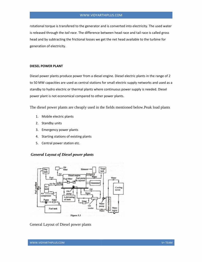
WWWVIDYARTHIPLUSCOM
WWWVIDYARTHIPLUSCOM V+ TEAM
This nuclear chain reaction can be controlled by using neutron poisons and
neutron moderators to change the portion of neutrons that will go on to cause more
fissions[60] Nuclear reactors generally have automatic and manual systems to shut the
fission reaction down if unsafe conditions are detected
Three nuclear powered ships (top to bottom) nuclear cruisers USS Bainbridge and USS Long
Beach with USS Enterprise the first nuclear powered aircraft carrier in 1964 Crew members are
spelling out Einsteins mass-energy equivalence formula E = mc2 on the flight deck
There are many different reactor designs utilizing different fuels and coolants and
incorporating different control schemes Some of these designs have been engineered to
meet a specific need Reactors for nuclear submarines and large naval ships for example
commonly use highly enriched uranium as a fuel This fuel choice increases the reactors
power density and extends the usable life of the nuclear fuel load but is more expensive
and a greater risk to nuclear proliferation than some of the other nuclear fuels
A number of new designs for nuclear power generation collectively
known as the Generation IV reactors are the subject of active research and may be used
for practical power generation in the future Many of these new designs specifically
attempt to make fission reactors cleaner safer andor less of a risk to the proliferation of
nuclear weapons Passively safe plants (such as the ESBWR) are available to be builtand
other designs that are believed to be nearly fool-proof are being pursued Fusion reactors
which may be viable in the future diminish or eliminate many of the risks associated
with nuclear fission There are trades to be made between safety economic and technical
properties of different reactor designs for particular applications Historically these
decisions were often made in private by scientists regulators and engineers but this may
be considered problematic and since Chernobyl and Three Mile Island many involved
now consider informed consent and morality should be primary considerations
Cooling system
A cooling system removes heat from the reactor core and transports it to
another area of the plant where the thermal energy can be harnessed to produce
WWWVIDYARTHIPLUSCOM
WWWVIDYARTHIPLUSCOM V+ TEAM
electricity or to do other useful work Typically the hot coolant will be used as a heat
source for a boiler and the pressurized steam from that boiler will power one or more
steam turbine driven electrical generators
Flexibility of nuclear power plants
It is often claimed that nuclear stations are inflexible in their output
implying that other forms of energy would be required to meet peak demand While that
is true for the vast majority of reactors this is no longer true of at least some modern
designs Nuclear plants are routinely used in load following mode on a large scale in
France Unit A at the German Biblis Nuclear Power Plant is designed to in- and decrease
his output 15 per minute between 40 and 100 of its nominal power Boiling water
reactors normally have load-following capability implemented by varying the
recirculation water flow
GASS TURBINE POWER PLANT
A gas turbine also called a combustion turbine is a type of internal
combustion engine It has an upstream rotating compressor coupled to a downstream
turbine and a combustion chamber in-between
Energy is added to the gas stream in the combustor where fuel is mixed with
air and ignited In the high pressure environment of the combustor combustion of the
fuel increases the temperature The products of the combustion are forced into the turbine
section There the high velocity and volume of the gas flow is directed through a nozzle
over the turbines blades spinning the turbine which powers the compressor and for
some turbines drives their mechanical output The energy given up to the turbine comes
from the reduction in the temperature and pressure of the exhaust gas
COMBINED POWER CYCLES
In electric power generation a combined cycle is an assembly of heat engines that work
in tandem off the same source of heat converting it into mechanical energy which in
WWWVIDYARTHIPLUSCOM
WWWVIDYARTHIPLUSCOM V+ TEAM
turn usually drives electrical generators The principle is that the exhaust of one heat
engine is used as the heat source for another thus extracting more useful energy from the
heat increasing the systems overall efficiency This works because heat engines are only
able to use a portion of the energy their fuel generates (usually less than 50)
The remaining heat (eg hot exhaust fumes) from combustion is generally wasted
Combining two or more thermodynamic cycles results in improved overall efficiency
reducing fuel costs In stationary power plants a successful common combination is the
Brayton cycle (in the form of a turbine burning natural gas or synthesis gas from coal)
and the Rankine cycle (in the form of a steam power plant) Multiple stage turbine or
steam cylinders are also common
LOAD DURATION CURVE
A load duration curve (LDC) is used in electric power generation to illustrate
the relationship between generating capacity requirements and capacity utilization
A LDC is similar to a load curve but the demand data is ordered in descending
order of magnitude rather than chronologically The LDC curve shows the capacity
utilization requirements for each increment of load The height of each slice is a measure
of capacity and the width of each slice is a measure of the utilization rate or capacity
factor The product of the two is a measure of electrical energy (eg kilowatthours)
HIGH PRESSURE BOILERS
A boiler is a closed vessel in which water or other fluid is heated The heated or
vaporized fluid exits the boiler for use in various processes or heating applications
Most boilers produce steam to be used at saturation temperature that is
saturated steam Superheated steam boilers vaporize the water and then further heat the
steam in a superheater This provides steam at much higher temperature but can
decrease the overall thermal efficiency of the steam generating plant because the higher
steam temperature requires a higher flue gas exhaust temperature There are several ways
WWWVIDYARTHIPLUSCOM
WWWVIDYARTHIPLUSCOM V+ TEAM
to circumvent this problem typically by providing an economizer that heats the feed
water a combustion air heater in the hot flue gas exhaust path or both There are
advantages to superheated steam that may and often will increase overall efficiency of
both steam generation and its utilisation gains in input temperature to a turbine should
outweigh any cost in additional boiler complication and expense There may also be
practical limitations in using wet steam as entrained condensation droplets will damage
turbine blades
Superheated steam presents unique safety concerns because if any system
component fails and allows steam to escape the high pressure and temperature can cause
serious instantaneous harm to anyone in its path Since the escaping steam will initially
be completely superheated vapor detection can be difficult although the intense heat and
sound from such a leak clearly indicates its presence
Superheater operation is similar to that of the coils on an air conditioning unit
although for a different purpose The steam piping is directed through the flue gas path in
the boiler furnace The temperature in this area is typically between 1300ndash1600 degrees
Celsius Some superheaters are radiant type that is they absorb heat by radiation Others
are convection type absorbing heat from a fluid Some are a combination of the two
types Through either method the extreme heat in the flue gas path will also heat the
superheater steam piping and the steam within While the temperature of the steam in the
superheater rises the pressure of the steam does not the turbine or moving pistons offer a
continuously expanding space and the pressure remains the same as that of the boiler
Almost all steam superheater system designs remove droplets entrained in the steam to
prevent damage to the turbine blading and associated piping
SUPERCRITICAL BOILER
Supercritical steam generators (also known as Benson boilers) are frequently
used for the production of electric power They operate at supercritical pressure In
contrast to a subcritical boiler a supercritical steam generator operates at such a high
pressure (over 3200 psi2206 MPa or 2206 bar) that actual boiling ceases to occur and
WWWVIDYARTHIPLUSCOM
WWWVIDYARTHIPLUSCOM V+ TEAM
the boiler has no water - steam separation There is no generation of steam bubbles within
the water because the pressure is above the critical pressure at which steam bubbles
can form It passes below the critical point as it does work in the high pressure turbine
and enters the generators condenser This is more efficient resulting in slightly less fuel
use The term boiler should not be used for a supercritical pressure steam generator as
no boiling actually occurs in this device
FLUIDIZED BED BOILERS
The major portion of the coal available in India is of low quality high ash content
and low calorific value The traditional grate fuel firing systems have got limitations and
are techno-economically unviable to meet the challenges of future Fluidized bed
combustion has emerged as a viable alternative and has significant advantages over
conventional firing system and offers multiple benefits ndash compact boiler design fuel
flexibility higher combustion efficiency and reduced emission of noxious pollutants such
as SOx and NOx The fuels burnt in these boilers include coal washery rejects rice husk
bagasse amp other agricultural wastes The fluidized bed boilers have a wide capacity
range- 05 Thr to over 100 Thr
UNIT-II STEAM POWER PLANT
Coal needs to be stored at various stages of the preparation process and
conveyed around the CPP facilities Coal handling is part of the larger field of bulk
material handling and is a complex and vital part of the CPP
Stockpiles
Stockpiles provide surge capacity to various parts of the CPP ROM coal is
delivered with large variations in production rate of tonnes per hour (tph) A ROM
stockpile is used to allow the washplant to be fed coal at lower constant rate A
simple stockpile is formed by machinery dumping coal into a pile either from dump
trucks pushed into heaps with bulldozers or from conveyor booms More controlled
stockpiles are formed using stackers to form piles along the length of a conveyor and
WWWVIDYARTHIPLUSCOM
WWWVIDYARTHIPLUSCOM V+ TEAM
reclaimers to retrieve the coal when required for product loading etc Taller and
wider stockpiles reduce the land area required to store a set tonnage of coal Larger coal
stockpiles have a reduced rate of heat lost leading to a higher risk of spontaneous
combustion
Stacking
Travelling lugging boom stackers that straddle a feed conveyor are commonly used
to create coal stockpiles
Reclaiming
Tunnel conveyors can be fed by a continuous slot hopper or bunker beneath the
stockpile to reclaim material Front-end loaders and bulldozers can be used to push the
coal into feeders Sometimes front-end loaders are the only means of reclaiming coal
from the stockpile This has a low up-front capital cost but much higher operating costs
measured in dollars per tonne handled High-capacity stockpiles are commonly reclaimed
using bucket-wheel reclaimers These can achieve very high rates
ASH HANDLING SYSTEMS
Ash Handling Systems is the none un combusted portion or residue after taking
combustion of any solid fuel
Solid fuel is usually coal And any coal contains some non combustible portion which is
called ash Content of that coal
There are different types of ashes
bull Bottom ash
bull fly ash
WWWVIDYARTHIPLUSCOM
WWWVIDYARTHIPLUSCOM V+ TEAM
Bottom ash is the residue which remains in the solid form at the bottom and fly ash is the
light particle which goes out along with exhaust gases and usually they are collected in
chimneys
Taking their so formed ash away from the Plant Boiler is called ndash ASH HANDLING
SYSTEM This is done in either
bull Mechanical conveying
bull Pneumatic conveying
Mechanical system requires conveyors and Pneumatic system requires ndash compressed air
to carry out the ash
Ash Handling Systems
Bulk Material Handling Systems
Conveyors And Material Handling Equipments
Process Equipments And Storage Equipments
Portable Handling Equipments
Rotary Equipments
Pneumatic Conveying Systems
Magnetic Equipments
Vibratory Equipments
Spares
Overhead Bag Handling Systems
COMBUSTION EQUIPMENTS
Combustion control options range from electro mechanical through to full
microprocessor control systems to match both application and customer needs
Cochran supply an extensive range of fuel handling equipment to complement and
help ensure that the optimum performance from the combustion and control
equipment is maintained Fuel handling equipment includes gas boosters oil
WWWVIDYARTHIPLUSCOM
WWWVIDYARTHIPLUSCOM V+ TEAM
pumping and heating stations fuel metering and instrumentation packages are
available to match individual installation requirements
STOCKERS
A mechanical stoker is a device which feeds coal into the firebox of a boiler It is
standard equipment on large stationary boilers and was also fitted to large steam
locomotives to ease the burden of the fireman The locomotive type has a screw
conveyor (driven by an auxiliary steam engine) which feeds the coal into the
firebox The coal is then distributed across the grate by steam jets controlled by the
fireman Power stations usually use pulverized coal-fired boilers
PULVERISER
A pulverizer or grinder is a mechanical device for the grinding of many different
types of materials For example they are used to pulverize coal for combustion in
the steam-generating furnaces of fossil fuel power plants
Types of pulverizers
Ball and tube mills
A ball mill is a pulverizer that consists of a horizontal rotating cylinder up to three
diameters in length containing a charge of tumbling or cascading steel balls
pebbles or rods
A tube mill is a revolving cylinder of up to five diameters in length used for fine
pulverization of ore rock and other such materials the material mixed with water
is fed into the chamber from one end and passes out the other end as slime (slurry)
Ring and ball mill
This type of mill consists of two rings separated by a series of large balls The
lower ring rotates while the upper ring presses down on the balls via a set of spring
and adjuster assemblies The material to be pulverized is introduced into the center
WWWVIDYARTHIPLUSCOM
WWWVIDYARTHIPLUSCOM V+ TEAM
or side of the pulverizer (depending on the design) and is ground as the lower ring
rotates causing the balls to orbit between the upper and lower rings The pulverized
material is carried out of the mill by the flow of air moving through it The size of
the pulverized particles released from the grinding section of the mill is determined
by a classifer separator
Vertical roller mill
Similar to the ring and ball mill this mill uses large tires to crush the coal These
are usually found in utility plants
Raw coal is gravity-fed through a central feed pipe to the grinding table where it
flows outwardly by centrifugal action and is ground between the rollers and table
Hot primary air for drying and coal transport enters the windbox plenum
underneath the grinding table and flows upward through a swirl ring having
multiple sloped nozzles surrounding the grinding table The air mixes with and
dries coal in the grinding zone and carries pulverized coal particles upward into a
classifier
Fine pulverized coal exits the outlet section through multiple discharge coal pipes
leading to the burners while oversized coal particles are rejected and returned to
the grinding zone for further grinding Pyrites and extraneous dense impurity
material fall through the nozzle ring and are plowed by scraper blades attached to
the grinding table into the pyrites chamber to be removed Mechanically the
vertical roller mill is categorized as an applied force mill There are three grinding
roller wheel assemblies in the mill grinding section which are mounted on a
loading frame via pivot point The fixed-axis roller in each roller wheel assembly
rotates on a segmentally-lined grinding table that is supported and driven by a
planetary gear reducer direct-coupled to a motor The grinding force for coal
pulverization is applied by a loading frame This frame is connected by vertical
tension rods to three hydraulic cylinders secured to the mill foundation All forces
used in the pulverizing process are transmitted to the foundation via the gear
WWWVIDYARTHIPLUSCOM
WWWVIDYARTHIPLUSCOM V+ TEAM
reducer and loading elements The pendulum movement of the roller wheels
provides a freedom for wheels to move in a radial direction which results in no
radial loading against the mill housing during the pulverizing process
Depending on the required coal fineness there are two types of classifier that may
be selected for a vertical roller mill The dynamic classifier which consists of a
stationary angled inlet vane assembly surrounding a rotating vane assembly or
cage is capable of producing micron fine pulverized coal with a narrow particle
size distribution In addition adjusting the speed of the rotating cage can easily
change the intensity of the centrifugal force field in the classification zone to
achieve coal fineness control real-time to make immediate accommodation for a
change in fuel or boiler load conditions For the applications where a micron fine
pulverized coal is not necessary the static classifier which consists of a cone
equipped with adjustable vanes is an option at a lower cost since it contains no
moving parts With adequate mill grinding capacity a vertical mill equipped with a
static classifier is capable of producing a coal fineness up to 995 or higher lt50
mesh and 80 or higher lt200 mesh while one equipped with a dynamic classifier
produces coal fineness levels of 100 lt100 mesh and 95 lt200 mesh or better
Bowl mill
Similar to the vertical roller mill it also uses tires to crush coal There are two
types a deep bowl mill and a shallow bowl mill
Demolition pulverizer
An attachment fitted to an excavator Commonly used in demolition work to break
up large pieces of concrete
ELECTROSTATIC PRECIPITATOR
An electrostatic precipitator (ESP) or electrostatic air cleaner is a particulate
collection device that removes particles from a flowing gas (such as air) using the
WWWVIDYARTHIPLUSCOM
WWWVIDYARTHIPLUSCOM V+ TEAM
force of an induced electrostatic charge Electrostatic precipitators are highly
efficient filtration devices that minimally impede the flow of gases through the
device and can easily remove fine particulate matter such as dust and smoke from
the air stream[1] In contrast to wet scrubbers which apply energy directly to the
flowing fluid medium an ESP applies energy only to the particulate matter being
collected and therefore is very efficient in its consumption of energy (in the form of
electricity)
Modern industrial electrostatic precipitators
ESPs continue to be excellent devices for control of many industrial particulate
emissions including smoke from electricity-generating utilities (coal and oil fired)
salt cake collection from black liquor boilers in pulp mills and catalyst collection
from fluidized bed catalytic cracker units in oil refineries to name a few These
devices treat gas volumes from several hundred thousand ACFM to 25 million
ACFM (1180 msup3s) in the largest coal-fired boiler applications For a coal-fired
boiler the collection is usually performed downstream of the air preheater at about
160 degC (320 degF) which provides optimal resistivity of the coal-ash particles For
some difficult applications with low-sulfur fuel hot-end units have been built
operating above 371 degC (700 degF)
The original parallel platendashweighted wire design (described above) has evolved as
more efficient (and robust) discharge electrode designs were developed today
focusing on rigid (pipe-frame) discharge electrodes to which many sharpened
spikes are attached (barbed wire) maximizing corona production Transformer-
rectifier systems apply voltages of 50 ndash 100 kV at relatively high current densities
Modern controls such as an automatic voltage control minimize electric sparking
and prevent arcing (sparks are quenched within 12 cycle of the TR set) avoiding
damage to the components Automatic plate-rapping systems and hopper-
evacuation systems remove the collected particulate matter while on line
theoretically allowing ESPs to stay in operation for years at a time
WWWVIDYARTHIPLUSCOM
WWWVIDYARTHIPLUSCOM V+ TEAM
Wet electrostatic precipitator
A wet electrostatic precipitator (WESP or wet ESP) operates with saturated air
streams (100 relative humidity) WESPs are commonly used to remove liquid
droplets such as sulfuric acid mist from industrial process gas streams The WESP
is also commonly used where the gases are high in moisture content contain
combustible particulate have particles that are sticky in nature
The preferred and most modern type of WESP is a downflow tubular design This
design allows the collected moisture and particulate to form a slurry that helps to
keep the collection surfaces clean
Plate style and upflow design WESPs are very unreliable and should not be used in
applications where particulate is sticky in nature
Consumer-oriented electrostatic air cleaners
Plate precipitators are commonly marketed to the public as air purifier devices or as
a permanent replacement for furnace filters but all have the undesirable attribute of
being somewhat messy to clean A negative side-effect of electrostatic precipitation
devices is the production of toxic ozone and NOx However electrostatic
precipitators offer benefits over other air purifications technologies such as HEPA
filtration which require expensive filters and can become production sinks for
many harmful forms of bacteria
The two-stage design (charging section ahead of collecting section) has the benefit
of minimizing ozone production which would adversely affect health of personnel
working in enclosed spaces For shipboard engine rooms where gearboxes generate
an oil fog two-stage ESPs are used to clean the air improving the operating
environment and preventing buildup of flammable oil fog accumulations Collected
oil is returned to the gear lubricating system
WWWVIDYARTHIPLUSCOM
WWWVIDYARTHIPLUSCOM V+ TEAM
With electrostatic precipitators if the collection plates are allowed to accumulate
large amounts of particulate matter the particles can sometimes bond so tightly to
the metal plates that vigorous washing and scrubbing may be required to
completely clean the collection plates The close spacing of the plates can make
thorough cleaning difficult and the stack of plates often cannot be easily
disassembled for cleaning One solution suggested by several manufacturers is to
wash the collector plates in a dishwasher
Some consumer precipitation filters are sold with special soak-off cleaners where
the entire plate array is removed from the precipitator and soaked in a large
container overnight to help loosen the tightly bonded particulates
A study by the Canada Mortgage and Housing Corporation testing a variety of
forced-air furnace filters found that ESP filters provided the best and most cost-
effective means of cleaning air using a forced-air system
DRAUGHT
Most boilers now depend on mechanical draught equipment rather than natural
draught This is because natural draught is subject to outside air conditions and
temperature of flue gases leaving the furnace as well as the chimney height All
these factors make proper draught hard to attain and therefore make mechanical
draught equipment much more economical
There are three types of mechanical draught
Induced draught This is obtained one of three ways the first being the stack effect of a
heated chimney in which the flue gas is less dense than the ambient air surrounding the
boiler The denser column of ambient air forces combustion air into and through the
boiler The second method is through use of a steam jet The steam jet oriented in the
direction of flue gas flow induces flue gasses into the stack and allows for a greater flue
gas velocity increasing the overall draught in the furnace This method was common on
steam driven locomotives which could not have tall chimneys The third method is by
WWWVIDYARTHIPLUSCOM
WWWVIDYARTHIPLUSCOM V+ TEAM
simply using an induced draught fan (ID fan) which removes flue gases from the furnace
and forces the exhaust gas up the stack Almost all induced draught furnaces operate with
a slightly negative pressure
Forced draught Draught is obtained by forcing air into the furnace by means of a fan (FD
fan) and ductwork Air is often passed through an air heater which as the name suggests
heats the air going into the furnace in order to increase the overall efficiency of the boiler
Dampers are used to control the quantity of air admitted to the furnace Forced draught
furnaces usually have a positive pressure
Balanced draught Balanced draught is obtained through use of both induced and forced
draught This is more common with larger boilers where the flue gases have to travel a
long distance through many boiler passes The induced draught fan works in conjunction
with the forced draught fan allowing the furnace pressure to be maintained slightly below
atmospheric
SURFACE CONDERSER
Surface condenser is the commonly used term for a water-cooled shell and tube
heat exchanger installed on the exhaust steam from a steam turbine in thermal
power stations These condensers are heat exchangers which convert steam from its
gaseous to its liquid state at a pressure below atmospheric pressure Where cooling
water is in short supply an air-cooled condenser is often used An air-cooled
condenser is however significantly more expensive and cannot achieve as low a
steam turbine exhaust pressure as a water cooled surface condenser
Surface condensers are also used in applications and industries other than the
condensing of steam turbine exhaust in power plants
In thermal power plants the primary purpose of a surface condenser is to condense
the exhaust steam from a steam turbine to obtain maximum efficiency and also to
convert the turbine exhaust steam into pure water (referred to as steam condensate)
so that it may be reused in the steam generator or boiler as boiler feed water
WWWVIDYARTHIPLUSCOM
WWWVIDYARTHIPLUSCOM V+ TEAM
The steam turbine itself is a device to convert the heat in steam to mechanical
power The difference between the heat of steam per unit weight at the inlet to the
turbine and the heat of steam per unit weight at the outlet to the turbine represents
the heat which is converted to mechanical power Therefore the more the
conversion of heat per pound or kilogram of steam to mechanical power in the
turbine the better is its efficiency By condensing the exhaust steam of a turbine at
a pressure below atmospheric pressure the steam pressure drop between the inlet
and exhaust of the turbine is increased which increases the amount of heat
available for conversion to mechanical power Most of the heat liberated due to
condensation of the exhaust steam is carried away by the cooling medium (water or
air) used by the surface condenser
COOLING TOWERS
Cooling towers are heat removal devices used to transfer process waste heat to the
atmosphere Cooling towers may either use the evaporation of water to remove
process heat and cool the working fluid to near the wet-bulb air temperature or in
the case of Close Circuit Dry Cooling Towers rely solely on air to cool the
working fluid to near the dry-bulb air temperature Common applications include
cooling the circulating water used in oil refineries chemical plants power stations
and building cooling The towers vary in size from small roof-top units to very
large hyperboloid structures that can be up to 200 metres tall and 100 metres in
diameter or rectangular structures that can be over 40 metres tall and 80 metres
long Smaller towers are normally factory-built while larger ones are constructed
on site They are often associated with nuclear power plants in popular culture
although cooling towers are constructed on many types of buildings
Industrial cooling towers
Industrial cooling towers can be used to remove heat from various sources such as
machinery or heated process material The primary use of large industrial cooling
towers is to remove the heat absorbed in the circulating cooling water systems used
WWWVIDYARTHIPLUSCOM
WWWVIDYARTHIPLUSCOM V+ TEAM
in power plants petroleum refineries petrochemical plants natural gas processing
plants food processing plants semi-conductor plants and for other industrial
facilities such as in condensers of distillation columns for cooling liquid in
crystallization etc[2] The circulation rate of cooling water in a typical 700 MW
coal-fired power plant with a cooling tower amounts to about 71600 cubic metres
an hour (315000 US gallons per minute)[3] and the circulating water requires a
supply water make-up rate of perhaps 5 percent (ie 3600 cubic metres an hour)
If that same plant had no cooling tower and used once-through cooling water it
would require about 100000 cubic metres an hour [4] and that amount of water
would have to be continuously returned to the ocean lake or river from which it
was obtained and continuously re-supplied to the plant Furthermore discharging
large amounts of hot water may raise the temperature of the receiving river or lake
to an unacceptable level for the local ecosystem Elevated water temperatures can
kill fish and other aquatic organisms (See thermal pollution) A cooling tower
serves to dissipate the heat into the atmosphere instead and wind and air diffusion
spreads the heat over a much larger area than hot water can distribute heat in a body
of water Some coal-fired and nuclear power plants located in coastal areas do
make use of once-through ocean water But even there the offshore discharge
water outlet requires very careful design to avoid environmental problems
Petroleum refineries also have very large cooling tower systems A typical large
refinery processing 40000 metric tonnes of crude oil per day (300000 barrels
(48000 m3) per day) circulates about 80000 cubic metres of water per hour
through its cooling tower system
The worlds tallest cooling tower is the 200 metre tall cooling tower of
Niederaussem Power Station
Heat transfer methods
With respect to the heat transfer mechanism employed the main types are
WWWVIDYARTHIPLUSCOM
WWWVIDYARTHIPLUSCOM V+ TEAM
Wet cooling towers or simply open circuit cooling towers operate on the principle of
evaporation The working fluid and the evaporated fluid (usually H2O) are one and the
same
Dry Cooling Towers operate by heat transfer through a surface that separates the working
fluid from ambient air such as in a tube to air heat exchanger utilizing convective heat
transfer They do not use evaporation
Fluid coolers or Closed Circuit Cooling Towers are hybrids that pass the working fluid
through a tube bundle upon which clean water is sprayed and a fan-induced draft
applied The resulting heat transfer performance is much closer to that of a wet cooling
tower with the advantage provided by a dry cooler of protecting the working fluid from
environmental exposure and contamination
In a wet cooling tower (or Open Circuit Cooling Tower) the warm water can be
cooled to a temperature lower than the ambient air dry-bulb temperature if the air
is relatively dry (see dew point and psychrometrics) As ambient air is drawn past
a flow of water an small portion of the water evaporate the energy required by that
portion of the water to evaporate is taken from the remaining mass of water
reducing his temperature (aproximately by 970 BTU for each pound of evaporated
water) Evaporation results in saturated air conditions lowering the temperature of
the water process by the tower to a value close to wet bulb air temperature which is
lower than the ambient dry bulb air temperature the difference determined by the
humidity of the ambient air
To achieve better performance (more cooling) a medium called fill is used to
increase the surface area and the time of contact between the air and water flows
Splash fill consists of material placed to interrupt the water flow causing splashing
Film fill is composed of thin sheets of material (usually PVC) upon which the water
flows Both methods create increased surface area and time of contact between the
fluid (water) and the gas (air)
Air flow generation methods
WWWVIDYARTHIPLUSCOM
WWWVIDYARTHIPLUSCOM V+ TEAM
With respect to drawing air through the tower there are three types of cooling
towers
Natural draft which utilizes buoyancy via a tall chimney Warm moist air naturally rises
due to the density differential to the dry cooler outside air Warm moist air is less dense
than drier air at the same pressure This moist air buoyancy produces a current of air
through the tower
Mechanical draft which uses power driven fan motors to force or draw air through the
tower
Induced draft A mechanical draft tower with a fan at the discharge which pulls air
through tower The fan induces hot moist air out the discharge This produces low
entering and high exiting air velocities reducing the possibility of recirculation in which
discharged air flows back into the air intake This fanfin arrangement is also known as
draw-through (see Image 2 3)
Forced draft A mechanical draft tower with a blower type fan at the intake The fan
forces air into the tower creating high entering and low exiting air velocities The low
exiting velocity is much more susceptible to recirculation With the fan on the air intake
the fan is more susceptible to complications due to freezing conditions Another
disadvantage is that a forced draft design typically requires more motor horsepower than
an equivalent induced draft design The forced draft benefit is its ability to work with high
static pressure They can be installed in more confined spaces and even in some indoor
situations This fanfill geometry is also known as blow-through (see Image 4)
Fan assisted natural draft A hybrid type that appears like a natural draft though airflow is
assisted by a fan
Hyperboloid (aka hyperbolic) cooling towers (Image 1) have become the design
standard for all natural-draft cooling towers because of their structural strength and
minimum usage of material The hyperboloid shape also aids in accelerating the
upward convective air flow improving cooling efficiency They are popularly
associated with nuclear power plants However this association is misleading as
WWWVIDYARTHIPLUSCOM
WWWVIDYARTHIPLUSCOM V+ TEAM
the same kind of cooling towers are often used at large coal-fired power plants as
well Similarly not all nuclear power plants have cooling towers instead cooling
their heat exchangers with lake river or ocean water
Categorization by air-to-water flow
Crossflow
Crossflow is a design in which the air flow is directed perpendicular to the water
flow (see diagram below) Air flow enters one or more vertical faces of the cooling
tower to meet the fill material Water flows (perpendicular to the air) through the
fill by gravity The air continues through the fill and thus past the water flow into
an open plenum area A distribution or hot water basin consisting of a deep pan
with holes or nozzles in the bottom is utilized in a crossflow tower Gravity
distributes the water through the nozzles uniformly across the fill material
Counterflow
In a counterflow design the air flow is directly opposite to the water flow (see
diagram below) Air flow first enters an open area beneath the fill media and is then
drawn up vertically The water is sprayed through pressurized nozzles and flows
downward through the fill opposite to the air flow
Common to both designs
The interaction of the air and water flow allow a partial equalization and evaporation of
water
The air now saturated with water vapor is discharged from the cooling tower
WWWVIDYARTHIPLUSCOM
WWWVIDYARTHIPLUSCOM V+ TEAM
A collection or cold water basin is used to contain the water after its interaction with the
air flow
Both crossflow and counterflow designs can be used in natural draft and
mechanical draft cooling towers
UNIT-III NUCLEAR AND HYDEL POWER PLANT
NUCLEAR ENERGY
Nuclear Energy is the use of sustained Nuclear fission to generate heat and
do useful work Nuclear Electric Plants Nuclear Ships and Submarines use
controlled nuclear energy to heat water and produce steam while in space nuclear
energy decays naturally in a radioisotope thermoelectric generator Scientists are
experimenting with fusion energy for future generation but these experiments do
not currently generate useful energy
Nuclear power provides about 6 of the worlds energy and 13ndash14 of the
worlds electricity with the US France and Japan together accounting for about
50 of nuclear generated electricity Also more than 150 naval vessels using
nuclear propulsion have been built
Nuclear power is controversial and there is an ongoing debate about the use
of nuclear energy Proponents such as the World Nuclear Association and IAEA
contend that nuclear power is a sustainable energy source that reduces carbon
emissions Opponents such as Greenpeace International and NIRS believe that
nuclear power poses many threats to people and the environment
WWWVIDYARTHIPLUSCOM
WWWVIDYARTHIPLUSCOM V+ TEAM
Some serious nuclear and radiation accidents have occurred Nuclear power plant
accidents include the Chernobyl disaster (1986) Fukushima I nuclear accidents
(2011) and the Three Mile Island accident (1979)[10] Nuclear-powered submarine
mishaps include the K-19 reactor accident (1961) the K-27 reactor accident (1968)
and the K-431 reactor accident (1985) International research is continuing into
safety improvements such as passively safe plants and the possible future use of
nuclear fusion
NUCLEAR FISSION
In nuclear physics and nuclear chemistry nuclear fission is a nuclear
reaction in which the nucleus of an atom splits into smaller parts (lighter nuclei)
often producing free neutrons and photons (in the form of gamma rays) The two
nuclei produced are most often of comparable size typically with a mass ratio
around 32 for common fissile isotopes[1][2] Most fissions are binary fissions but
occasionally (2 to 4 times per 1000 events) three positively-charged fragments are
produced in a ternary fission The smallest of these ranges in size from a proton to
an argon nucleus
Fission is usually an energetic nuclear reaction induced by a neutron
although it is occasionally seen as a form of spontaneous radioactive decay
especially in very high-mass-number isotopes The unpredictable composition of
the products (which vary in a broad probabilistic and somewhat chaotic manner)
distinguishes fission from purely quantum-tunnelling processes such as proton
emission alpha decay and cluster decay which give the same products every time
Fission of heavy elements is an exothermic reaction which can release
large amounts of energy both as electromagnetic radiation and as kinetic energy of
the fragments (heating the bulk material where fission takes place) In order for
WWWVIDYARTHIPLUSCOM
WWWVIDYARTHIPLUSCOM V+ TEAM
fission to produce energy the total binding energy of the resulting elements must
be less than that of the starting element Fission is a form of nuclear transmutation
because the resulting fragments are not the same element as the original atom
NUCLEAR FUSION
In nuclear physics nuclear chemistry and astrophysics nuclear fusion is
the process by which two or more atomic nuclei join together or fuse to form a
single heavier nucleus This is usually accompanied by the release or absorption of
large quantities of energy Large-scale thermonuclear fusion processes involving
many nuclei fusing at once must occur in matter at very high densities and
temperatures
The fusion of two nuclei with lower masses than iron (which along with
nickel has the largest binding energy per nucleon) generally releases energy while
the fusion of nuclei heavier than iron absorbs energy The opposite is true for the
reverse process nuclear fission
In the simplest case of hydrogen fusion two protons must be brought close
enough for the weak nuclear force to convert either of the identical protons into a
neutron thus forming the hydrogen isotope deuterium In more complex cases of
heavy ion fusion involving two or more nucleons the reaction mechanism is
different but the same result occursmdash smaller nuclei are combined into larger
nuclei
Nuclear fusion occurs naturally in all active stars Synthetic fusion as a
result of human actions has also been achieved although this has not yet been
completely controlled as a source of nuclear power (see fusion power) In the
laboratory successful nuclear physics experiments have been carried out that
involve the fusion of many different varieties of nuclei but the energy output has
been negligible in these studies In fact the amount of energy put into the process
has always exceeded the energy output
WWWVIDYARTHIPLUSCOM
WWWVIDYARTHIPLUSCOM V+ TEAM
Uncontrolled nuclear fusion has been carried out many times in nuclear
weapons testing which results in a deliberate explosion These explosions have
always used the heavy isotopes of hydrogen deuterium (H-2) and tritium (H-3)
and never the much more common isotope of hydrogen (H-1) sometimes called
protium
Building upon the nuclear transmutation experiments by Ernest Rutherford
carried out several years earlier the fusion of the light nuclei (hydrogen isotopes)
was first accomplished by Mark Oliphant in 1932 Then the steps of the main cycle
of nuclear fusion in stars were first worked out by Hans Bethe throughout the
remainder of that decade
Research into fusion for military purposes began in the early 1940s as part
of the Manhattan Project but this was not accomplished until 1951 (see the
Greenhouse Item nuclear test) and nuclear fusion on a large scale in an explosion
was first carried out on November 1 1952 in the Ivy Mike hydrogen bomb test
Research into developing controlled thermonuclear fusion for civil purposes also
began in the 1950s and it continues to this day
TYPES OF REACTORS
Pressurized water reactors (PWRs) constitute a majority of all western nuclear
power plants and are one of two types of light water reactor (LWR) the other type
being boiling water reactors (BWRs) In a PWR the primary coolant (water) is
pumped under high pressure to the reactor core where it is heated by the energy
generated by the fission of atoms The heated water then flows to a steam generator
where it transfers its thermal energy to a secondary system where steam is
generated and flows to turbines which in turn spins an electric generator In
contrast to a boiling water reactor pressure in the primary coolant loop prevents the
water from boiling within the reactor All LWRs use ordinary light water as both
coolant and neutron moderator
WWWVIDYARTHIPLUSCOM
WWWVIDYARTHIPLUSCOM V+ TEAM
PWRs were originally designed to serve as nuclear propulsion for nuclear
submarines and were used in the original design of the second commercial power
plant at Shippingport Atomic Power Station
PWRs currently operating in the United States are considered Generation II
reactors Russias VVER reactors are similar to US PWRs France operates many
PWRs to generate the bulk of their electricity
Several hundred PWRs are used for marine propulsion in aircraft carriers nuclear
submarines and ice breakers In the US they were originally designed at the Oak
Ridge National Laboratory for use as a nuclear submarine power plant Follow-on
work was conducted by Westinghouse Bettis Atomic Power Laboratory[1] The first
commercial nuclear power plant at Shippingport Atomic Power Station was
originally designed as a pressurized water reactor on insistence from Admiral
Hyman G Rickover that a viable commercial plant would include none of the
crazy thermodynamic cycles that everyone else wants to build
The US Army Nuclear Power Program operated pressurized water reactors from
1954 to 1974
Three Mile Island Nuclear Generating Station initially operated two pressurized
water reactor plants TMI-1 and TMI-2 The partial meltdown of TMI-2 in 1979
essentially ended the growth in new construction nuclear power plants in the
United States
Design
WWWVIDYARTHIPLUSCOM
WWWVIDYARTHIPLUSCOM V+ TEAM
Pictorial explanation of power transfer in a pressurized water reactor Primary coolant is
in orange and the secondary coolant (steam and later feedwater) is in blue
Nuclear fuel in the reactor vessel is engaged in a fission chain reaction which
produces heat heating the water in the primary coolant loop by thermal conduction
through the fuel cladding The hot primary coolant is pumped into a heat exchanger
called the steam generator where it flows through hundreds or thousands of tubes
(usually 34 inch in diameter) Heat is transferred through the walls of these tubes
to the lower pressure secondary coolant located on the sheet side of the exchanger
where it evaporates to pressurized steam The transfer of heat is accomplished
without mixing the two fluids which is desirable since the primary coolant might
become radioactive Some common steam generator arrangements are u-tubes or
single pass heat exchangers In a nuclear power station the pressurized steam is fed
through a steam turbine which drives an electrical generator connected to the
electric grid for distribution After passing through the turbine the secondary
coolant (water-steam mixture) is cooled down and condensed in a condenser The
condenser converts the steam to a liquid so that it can be pumped back into the
steam generator and maintains a vacuum at the turbine outlet so that the pressure
drop across the turbine and hence the energy extracted from the steam is
maximized Before being fed into the steam generator the condensed steam
WWWVIDYARTHIPLUSCOM
WWWVIDYARTHIPLUSCOM V+ TEAM
(referred to as feedwater) is sometimes preheated in order to minimize thermal
shock
The steam generated has other uses besides power generation In nuclear ships and
submarines the steam is fed through a steam turbine connected to a set of speed
reduction gears to a shaft used for propulsion Direct mechanical action by
expansion of the steam can be used for a steam-powered aircraft catapult or similar
applications District heating by the steam is used in some countries and direct
heating is applied to internal plant applications
Two things are characteristic for the pressurized water reactor (PWR) when
compared with other reactor types coolant loop separation from the steam system
and pressure inside the primary coolant loop In a PWR there are two separate
coolant loops (primary and secondary) which are both filled with
demineralizeddeionized water A boiling water reactor by contrast has only one
coolant loop while more exotic designs such as breeder reactors use substances
other than water for coolant and moderator (eg sodium in its liquid state as coolant
or graphite as a moderator) The pressure in the primary coolant loop is typically
15ndash16 megapascals (150ndash160 bar) which is notably higher than in other nuclear
reactors and nearly twice that of a boiling water reactor (BWR) As an effect of
this only localized boiling occurs and steam will recondense promptly in the bulk
fluid By contrast in a boiling water reactor the primary coolant is designed to boil
PWR Reactor Design
WWWVIDYARTHIPLUSCOM
WWWVIDYARTHIPLUSCOM V+ TEAM
PWR Reactor Vessel
Coolant
Light water is used as the primary coolant in a PWR It enters the bottom of the
reactor core at about 275 degC (530 degF) and is heated as it flows upwards through the
reactor core to a temperature of about 315 degC (600 degF) The water remains liquid
despite the high temperature due to the high pressure in the primary coolant loop
usually around 155 bar (155 MPa 153 atm 2250 psig) In water the critical point
occurs at around 647 K (374 degC or 705 degF) and 22064 MPa (3200 PSIA or 218
atm)[7]
WWWVIDYARTHIPLUSCOM
WWWVIDYARTHIPLUSCOM V+ TEAM
Pressure in the primary circuit is maintained by a pressurizer a separate vessel that
is connected to the primary circuit and partially filled with water which is heated to
the saturation temperature (boiling point) for the desired pressure by submerged
electrical heaters To achieve a pressure of 155 bar the pressurizer temperature is
maintained at 345 degC which gives a subcooling margin (the difference between the
pressurizer temperature and the highest temperature in the reactor core) of 30 degC
Thermal transients in the reactor coolant system result in large swings in
pressurizer liquid volume total pressurizer volume is designed around absorbing
these transients without uncovering the heaters or emptying the pressurizer
Pressure transients in the primary coolant system manifest as temperature transients
in the pressurizer and are controlled through the use of automatic heaters and water
spray which raise and lower pressurizer temperature respectively
To achieve maximum heat transfer the primary circuit temperature pressure and
flow rate are arranged such that subcooled nucleate boiling takes place as the
coolant passes over the nuclear fuel rods
The coolant is pumped around the primary circuit by powerful pumps which can
consume up to 6 MW each After picking up heat as it passes through the reactor
core the primary coolant transfers heat in a steam generator to water in a lower
pressure secondary circuit evaporating the secondary coolant to saturated steam mdash
in most designs 62 MPa (60 atm 900 psia) 275 degC (530 degF) mdash for use in the
steam turbine The cooled primary coolant is then returned to the reactor vessel to
be heated again
Moderator
Pressurized water reactors like all thermal reactor designs require the fast fission
neutrons to be slowed down (a process called moderation or thermalization) in
order to interact with the nuclear fuel and sustain the chain reaction In PWRs the
coolant water is used as a moderator by letting the neutrons undergo multiple
collisions with light hydrogen atoms in the water losing speed in the process This
WWWVIDYARTHIPLUSCOM
WWWVIDYARTHIPLUSCOM V+ TEAM
moderating of neutrons will happen more often when the water is denser (more
collisions will occur) The use of water as a moderator is an important safety
feature of PWRs as an increase in temperature may cause the water to turn to
steam - thereby reducing the extent to which neutrons are slowed down and hence
reducing the reactivity in the reactor Therefore if reactivity increases beyond
normal the reduced moderation of neutrons will cause the chain reaction to slow
down producing less heat This property known as the negative temperature
coefficient of reactivity makes PWR reactors very stable
In contrast the RBMK reactor design used at Chernobyl which uses graphite
instead of water as the moderator and uses boiling water as the coolant has a large
positive thermal coefficient of reactivity that increases heat generation when
coolant water temperatures increase This makes the RBMK design less stable than
pressurized water reactors In addition to its property of slowing down neutrons
when serving as a moderator water also has a property of absorbing neutrons
albeit to a lesser degree When the coolant water temperature increases the boiling
increases which creates voids Thus there is less water to absorb thermal neutrons
that have already been slowed down by the graphite moderator causing an increase
in reactivity This property is called the void coefficient of reactivity and in an
RBMK reactor like Chernobyl the void coefficient is positive and fairly large
causing rapid transients This design characteristic of the RBMK reactor is
generally seen as one of several causes of the Chernobyl accident[10]
Heavy water has very low neutron absorption so heavy water reactors such as
CANDU reactors also have a positive void coefficient though it is not as large as
that of an RBMK like Chernobyl these reactors are designed with a number of
safety systems not found in the original RBMK design which are designed to
handle or react to this as needed
PWRs are designed to be maintained in an undermoderated state meaning that
there is room for increased water volume or density to further increase moderation
because if moderation were near saturation then a reduction in density of the
WWWVIDYARTHIPLUSCOM
WWWVIDYARTHIPLUSCOM V+ TEAM
moderatorcoolant could reduce neutron absorption significantly while reducing
moderation only slightly making the void coefficient positive Also light water is
actually a somewhat stronger moderator of neutrons than heavy water though
heavy waters neutron absorption is much lower Because of these two facts light
water reactors have a relatively small moderator volume and therefore have
compact cores One next generation design the supercritical water reactor is even
less moderated A less moderated neutron energy spectrum does worsen the
capturefission ratio for 235U and especially 239Pu meaning that more fissile nuclei
fail to fission on neutron absorption and instead capture the neutron to become a
heavier nonfissile isotope wasting one or more neutrons and increasing
accumulation of heavy transuranic actinides some of which have long half-lives
Fuel
PWR fuel bundle This fuel bundle is from a pressurized water reactor of the nuclear
passenger and cargo ship NS Savannah Designed and built by the Babcock and Wilcox
Company
After enrichment the uranium dioxide (UO2) powder is fired in a high-temperature
sintering furnace to create hard ceramic pellets of enriched uranium dioxide The
cylindrical pellets are then clad in a corrosion-resistant zirconium metal alloy
Zircaloy which are backfilled with helium to aid heat conduction and detect
leakages Zircaloy is chosen because of its mechanical properties and its low
absorption cross section The finished fuel rods are grouped in fuel assemblies
called fuel bundles that are then used to build the core of the reactor A typical
PWR has fuel assemblies of 200 to 300 rods each and a large reactor would have
about 150ndash250 such assemblies with 80ndash100 tonnes of uranium in all Generally
the fuel bundles consist of fuel rods bundled 14 times 14 to 17 times 17 A PWR produces
on the order of 900 to 1500 MWe PWR fuel bundles are about 4 meters in length
Refuelings for most commercial PWRs is on an 18ndash24 month cycle
Approximately one third of the core is replaced each refueling though some more
WWWVIDYARTHIPLUSCOM
WWWVIDYARTHIPLUSCOM V+ TEAM
modern refueling schemes may reduce refuel time to a few days and allow
refueling to occur on a shorter periodicity
Control
In PWRs reactor power can be viewed as following steam (turbine) demand due to
the reactivity feedback of the temperature change caused by increased or decreased
steam flow (See Negative temperature coefficient) Boron and control rods are
used to maintain primary system temperature at the desired point In order to
decrease power the operator throttles shut turbine inlet valves This would result in
less steam being drawn from the steam generators This results in the primary loop
increasing in temperature The higher temperature causes the reactor to fission less
and decrease in power The operator could then add boric acid andor insert control
rods to decrease temperature to the desired point
Reactivity adjustment to maintain 100 power as the fuel is burned up in most
commercial PWRs is normally achieved by varying the concentration of boric acid
dissolved in the primary reactor coolant Boron readily absorbs neutrons and
increasing or decreasing its concentration in the reactor coolant will therefore affect
the neutron activity correspondingly An entire control system involving high
pressure pumps (usually called the charging and letdown system) is required to
remove water from the high pressure primary loop and re-inject the water back in
with differing concentrations of boric acid The reactor control rods inserted
through the reactor vessel head directly into the fuel bundles are moved for the
following reasons
To start up the reactor
To shut down the primary nuclear reactions in the reactor
To accommodate short term transients such as changes to load on the turbine
The control rods can also be used
To compensate for nuclear poison inventory
WWWVIDYARTHIPLUSCOM
WWWVIDYARTHIPLUSCOM V+ TEAM
To compensate for nuclear fuel depletion
but these effects are more usually accommodated by altering the primary coolant
boric acid concentration
In contrast BWRs have no boron in the reactor coolant and control the reactor
power by adjusting the reactor coolant flow rate
Advantages
PWR reactors are very stable due to their tendency to produce less power as
temperatures increase this makes the reactor easier to operate from a stability
standpoint as long as the post shutdown period of 1 to 3 years[citation needed] has pumped
cooling
PWR turbine cycle loop is separate from the primary loop so the water in the secondary
loop is not contaminated by radioactive materials
PWRs can passively scram the reactor in the event that offsite power is lost to
immediately stop the primary nuclear reaction The control rods are held by
electromagnets and fall by gravity when current is lost full insertion safely shuts down
the primary nuclear reaction However nuclear reactions of the fission products continue
to generate decay heat at initially roughly 7 of full power level which requires 1 to 3
years of water pumped cooling If cooling fails during this post-shutdown period the
reactor can still overheat and meltdown Upon loss of coolant the decay heat can raise
the rods above 2200 degrees Celsius where upon the hot Zirconium alloy metal used for
casing the nuclear fuel rods spontaneously explodes in contact with the cooling water or
steam which leads to the separation of water in to its constituent elements (hydrogen
and oxygen) In this event there is a high danger of hydrogen explosions threatening
structural damage andor the exposure of highly radioactive stored fuel rods in the
vicinity outside the plant in pools (approximately 15 tons of fuel is replenished each year
to maintain normal PWR operation)
Disadvantages
WWWVIDYARTHIPLUSCOM
WWWVIDYARTHIPLUSCOM V+ TEAM
The coolant water must be highly pressurized to remain liquid at high temperatures This
requires high strength piping and a heavy pressure vessel and hence increases
construction costs The higher pressure can increase the consequences of a loss-of-
coolant accident[14] The reactor pressure vessel is manufactured from ductile steel but as
the plant is operated neutron flux from the reactor causes this steel to become less
ductile Eventually the ductility of the steel will reach limits determined by the applicable
boiler and pressure vessel standards and the pressure vessel must be repaired or
replaced This might not be practical or economic and so determines the life of the plant
Additional high pressure components such as reactor coolant pumps pressurizer steam
generators etc are also needed This also increases the capital cost and complexity of a
PWR power plant
The high temperature water coolant with boric acid dissolved in it is corrosive to carbon
steel (but not stainless steel) this can cause radioactive corrosion products to circulate in
the primary coolant loop This not only limits the lifetime of the reactor but the systems
that filter out the corrosion products and adjust the boric acid concentration add
significantly to the overall cost of the reactor and to radiation exposure Occasionally this
has resulted in severe corrosion to control rod drive mechanisms when the boric acid
solution leaked through the seal between the mechanism itself and the primary system
Natural uranium is only 07 uranium-235 the isotope necessary for thermal reactors
This makes it necessary to enrich the uranium fuel which increases the costs of fuel
production If heavy water is used it is possible to operate the reactor with natural
uranium but the production of heavy water requires large amounts of energy and is
hence expensive
Because water acts as a neutron moderator it is not possible to build a fast neutron
reactor with a PWR design A reduced moderation water reactor may however achieve a
breeding ratio greater than unity though this reactor design has disadvantages of its own
Boiling Water Reactor
WWWVIDYARTHIPLUSCOM
WWWVIDYARTHIPLUSCOM V+ TEAM
The boiling water reactor (BWR) is a type of light water nuclear reactor used for
the generation of electrical power It is the second most common type of electricity-
generating nuclear reactor after the pressurized water reactor (PWR) also a type of
light water nuclear reactor The BWR was developed by the Idaho National
Laboratory and General Electric in the mid-1950s The main present manufacturer
is GE Hitachi Nuclear Energy which specializes in the design and construction of
this type of reactor
Early concepts
The BWR concept was developed slightly later than the PWR concept
Development of the BWR started in the early 1950s and was a collaboration
between GE and several US national laboratories
Research into nuclear power in the US was led by the 3 military services The
Navy seeing the possibility of turning submarines into full-time underwater
vehicles and ships that could steam around the world without refueling sent their
man in engineering Captain Hyman Rickover to run their nuclear power program
Rickover decided on the PWR route for the Navy as the early researchers in the
field of nuclear power feared that the direct production of steam within a reactor
would cause instability while they knew that the use of pressurized water would
definitively work as a means of heat transfer This concern led to the USs first
research effort in nuclear power being devoted to the PWR which was highly
suited for naval vessels (submarines especially) as space was at a premium and
PWRs could be made compact and high-power enough to fit in such in any event
But other researchers wanted to investigate whether the supposed instability caused
by boiling water in a reactor core would really cause instability In particular
Samuel Untermyer II a researcher at Idaho National Laboratory (INL) proposed
and oversaw a series of experiments the BORAX experimentsmdashto see if a boiling
water reactor would be feasible for use in energy production He found that it was
WWWVIDYARTHIPLUSCOM
WWWVIDYARTHIPLUSCOM V+ TEAM
after subjecting his reactors to quite strenuous tests proving the safety principles of
the BWR
Following this series of tests GE got involved and collaborated with INL to bring
this technology to market Larger-scale tests were conducted through the late
1950searlymid-1960s that only partially used directly-generated (primary) nuclear
boiler system steam to feed the turbine and incorporated heat exchangers for the
generation of secondary steam to drive separate parts of the turbines The literature
does not indicate why this was the case but it was eliminated on production models
of the BWR
First series of production BWRs (BWR1ndashBWR6)
The first generation of production boiling water reactors saw the incremental
development of the unique and distinctive features of the BWR the torus (used to
quench steam in the event of a transient requiring the quenching of steam) as well
as the drywell the elimination of the heat exchanger the steam dryer the
distinctive general layout of the reactor building and the standardization of reactor
control and safety systems The first General Electric series of production BWRs
evolved through 6 iterative design phases each termed BWR1 through BWR6
(BWR4s BWR5s and BWR6s are the most common types in service today) The
vast majority of BWRs in service throughout the world belong to one of these
design phases
1st generation BWR BWR1 with Mark I containment
2nd generation BWRs BWR2 BWR3 and some BWR4 with Mark I containment Other
BWR4 and BWR5 with Mark-II containment
3rd generation BWRs BWR6 with Mark-III containment
WWWVIDYARTHIPLUSCOM
WWWVIDYARTHIPLUSCOM V+ TEAM
Browns Ferry Unit 1 drywell and wetwell under construction a BWR4 using the Mark I
containment
Containment variants were constructed using either concrete or steel for the
Primary Containment Drywell and Wetwell in various combinations[5]
Apart from the GE designs there were others by ABB MITSU Toshiba and KWU
See List of boiling water reactors
The advanced boiling water reactor (ABWR)
A newer design of BWR is known as the Advanced Boiling Water Reactor
(ABWR) The ABWR was developed in the late 1980s and early 1990s and has
been further improved to the present day The ABWR incorporates advanced
technologies in the design including computer control plant automation control
rod removal motion and insertion in-core pumping and nuclear safety to deliver
improvements over the original series of production BWRs with a high power
output (1350 MWe per reactor) and a significantly lowered probability of core
damage Most significantly the ABWR was a completely standardized design that
could be made for series production[citation needed]
The ABWR was approved by the US Nuclear Regulatory Commission for
production as a standardized design in the early 1990s Subsequently numerous
ABWRs were built in Japan One development spurred by the success of the
ABWR in Japan is that GEs nuclear energy division merged with Hitachi
Corporations nuclear energy division forming GE Hitachi who is now the major
worldwide developer of the BWR design
The simplified boiling water reactor (SBWR)
WWWVIDYARTHIPLUSCOM
WWWVIDYARTHIPLUSCOM V+ TEAM
General Electric (GE) also developed a different concept for a new boiling water
reactor (BWR) at the same time as the ABWR known as the simplified boiling
water reactor (SBWR) This smaller (600 megawatt electrical (MWe) per reactor)
was notable for its incorporationmdashfor the first time ever in a light water reactormdash
of passive safety design principles The concept of passive safety means that the
reactor rather than requiring the intervention of active systems such as emergency
injection pumps to keep the reactor within safety margins was instead designed to
return to a safe state solely through operation of natural forces if a safety-related
contingency developed
For example if the reactor got too hot it would trigger a system that would release
soluble neutron absorbers (generally a solution of borated materials or a solution of
borax) or materials that greatly hamper a chain reaction by absorbing neutrons
into the reactor core The tank containing the soluble neutron absorbers would be
located above the reactor and the absorption solution once the system was
triggered would flow into the core through force of gravity and bring the reaction
to a near-complete stop Another example was the Isolation Condenser system
which relied on the principle of hot watersteam rising to bring hot coolant into
large heat exchangers located above the reactor in very deep tanks of water thus
accomplishing residual heat removal Yet another example was the omission of
recirculation pumps within the core these pumps were used in other BWR designs
to keep cooling water moving they were expensive hard to reach to repair and
could occasionally fail so as to improve reliability the ABWR incorporated no less
than 10 of these recirculation pumps so that even if several failed a sufficient
number would remain serviceable so that an unscheduled shutdown would not be
necessary and the pumps could be repaired during the next refueling outage
Instead the designers of the Simplified Boiling Water Reactor used thermal
analysis to design the reactor core such that natural circulation (cold water falls hot
water rises) would bring water to the center of the core to be boiled
The ultimate result of the passive safety features of the SBWR would be a reactor
that would not require human intervention in the event of a major safety
WWWVIDYARTHIPLUSCOM
WWWVIDYARTHIPLUSCOM V+ TEAM
contingency for at least 48 hours following the safety contingency thence it would
only require periodic refilling of cooling water tanks located completely outside of
the reactor isolated from the cooling system and designed to remove reactor waste
heat through evaporation The Simplified Boiling Water Reactor was submitted to
the United States Nuclear Regulatory Commission however it was withdrawn
prior to approval still the concept remained intriguing to General Electrics
designers and served as the basis of future developments
The economic simplified boiling water reactor (ESBWR)
During a period beginning in the late 1990s GE engineers proposed to combine the
features of the advanced boiling water reactor design with the distinctive safety
features of the simplified boiling water reactor design along with scaling up the
resulting design to a larger size of 1600 MWe (4500 MWth) This Economic
Simplified Boiling Water Reactor design has been submitted to the US Nuclear
Regulatory Commission for approval and the subsequent Final Design Review is
near completion
Reportedly this design has been advertised as having a core damage probability of
only 3times10minus8 core damage events per reactor-year[citation needed] (That is there would
need to be 3 million ESBWRs operating before one would expect a single core-
damaging event during their 100-year lifetimes Earlier designs of the BWR (the
BWR4) had core damage probabilities as high as 1times10minus5 core-damage events per
reactor-year)[6] This extraordinarily low CDP for the ESBWR far exceeds the other
large LWRs on the market
Advantages and disadvantages
WWWVIDYARTHIPLUSCOM
WWWVIDYARTHIPLUSCOM V+ TEAM
Advantages
The reactor vessel and associated components operate at a substantially lower
pressure (about 75 times atmospheric pressure) compared to a PWR (about 158
times atmospheric pressure)
Pressure vessel is subject to significantly less irradiation compared to a PWR and
so does not become as brittle with age
Operates at a lower nuclear fuel temperature
Fewer components due to no steam generators and no pressurizer vessel (Older
BWRs have external recirculation loops but even this piping is eliminated in
modern BWRs such as the ABWR)
Lower risk (probability) of a rupture causing loss of coolant compared to a PWR
and lower risk of core damage should such a rupture occur This is due to fewer
pipes fewer large diameter pipes fewer welds and no steam generator tubes
NRC assessments of limiting fault potentials indicate if such a fault occurred the
average BWR would be less likely to sustain core damage than the average PWR
due to the robustness and redundancy of the Emergency Core Cooling System
(ECCS)
Unlike PWRs BWRs have at least a few steam-turbine driven ECCS systems that
can be directly operated by steam produced after a reactor shutdown and
require no electrical power This results in less dependence on emergency diesel
generatorsmdashof which there are fourmdashin any event
Measuring the water level in the pressure vessel is the same for both normal and
emergency operations which results in easy and intuitive assessment of
emergency conditions
Can operate at lower core power density levels using natural circulation without
forced flow
A BWR may be designed to operate using only natural circulation so that
recirculation pumps are eliminated entirely (The new ESBWR design uses natural
circulation)
BWRs do not use boric acid to control fission burn-up leading to less possibility of
corrosion within the reactor vessel and piping (Corrosion from boric acid must be
WWWVIDYARTHIPLUSCOM
WWWVIDYARTHIPLUSCOM V+ TEAM
carefully monitored in PWRs it has been demonstrated that reactor vessel head
corrosion can occur if the reactor vessel head is not properly maintained See
Davis-Besse Since BWRs do not utilize boric acid these contingencies are
eliminated)
BWRs generally have N-2 redundancy on their major safety-related systems
which normally consist of four trains of components This generally means that
up to two of the four components of a safety system can fail and the system will
still perform if called upon
Due to their single major vendor (GEHitachi) the current fleet of BWRs have
predictable uniform designs that while not completely standardized generally
are very similar to one another The ABWRESBWR designs are completely
standardized Lack of standardization remains a problem with PWRs as at least in
the United States there are three design families represented among the current
PWR fleet (Combustion Engineering Westinghouse and Babcock amp Wilcox)
within these families there are quite divergent designs
Additional families of PWRs are being introduced For example Mitsubishis
APWR Arevas US-EPR and Westinghouses AP1000AP600 will add diversity and
complexity to an already diverse crowd and possibly cause customers seeking
stability and predictability to seek other designs such as the BWR
BWRs are overrepresented in imports if the importing nation doesnt have a
nuclear navy (PWRs are favored by nuclear naval states due to their compact
high-power design used on nuclear-powered vessels since naval reactors are
generally not exported they cause national skill to be developed in PWR design
construction and operation) or special national aspirations (special national
aspirations lead to a marked preference for the CANDU reactor type due to
special features of that type) This may be due to the fact that BWRs are ideally
suited for peaceful uses like power generation processindustrialdistrict heating
and desalinization due to low cost simplicity and safety focus which come at
the expense of larger size and slightly lower thermal efficiency
Sweden is standardized mainly on BWRs
Mexicos only two reactors are BWRs
WWWVIDYARTHIPLUSCOM
WWWVIDYARTHIPLUSCOM V+ TEAM
Japan experimented with both PWRs and BWRs but most builds as of late have
been of BWRs specifically ABWRs
In the CEGB open competition in the early 1960s for a standard design for UK
2nd-generation power reactors the PWR didnt even make it to the final round
which was a showdown between the BWR (preferred for its easily understood
design as well as for being predictable and boring) and the AGCR a uniquely
British design the indigenous design won possibly on technical merits possibly
due to the proximity of a general election
Disadvantages
Much larger pressure vessel than for a PWR of similar power with
correspondingly higher cost (However the overall cost is reduced because a
modern Complex calculations for managing consumption of nuclear fuel during
operation due to two phase (water and steam) fluid flow in the upper part of
the core This requires more instrumentation in the reactor core The innovation
of computers however makes this less of an issue
BWR has no main steam generators and associated piping)
Contamination of the turbine by short-lived activation products This means that
shielding and access control around the steam turbine are required during normal
operations due to the radiation levels arising from the steam entering directly
from the reactor core This is a moderately minor concern as most of the
radiation flux is due to Nitrogen-16 which has a half-life measured in seconds
allowing the turbine chamber to be entered into within minutes of shutdown
Though the present fleet of BWRs are said to be less likely to suffer core damage
from the 1 in 100000 reactor-year limiting fault than the present fleet of PWRs
are (due to increased ECCS robustness and redundancy) there have been
concerns raised about the pressure containment ability of the as-built
unmodified Mark I containment ndash that such may be insufficient to contain
pressures generated by a limiting fault combined with complete ECCS failure that
results in extremely severe core damage In this double failure scenario assumed
to be extremely unlikely prior to the Fukushima I nuclear accidents an
WWWVIDYARTHIPLUSCOM
WWWVIDYARTHIPLUSCOM V+ TEAM
unmodified Mark I containment can allow some degree of radioactive release to
occur This is supposed to be mitigated by the modification of the Mark I
containment namely the addition of an outgas stack system that if containment
pressure exceeds critical setpoints is supposed to allow the orderly discharge of
pressurizing gases after the gases pass through activated carbon filters designed
to trap radionuclides[7]
A BWR requires active cooling for a period of several hours to several days
following shutdown depending on its power history Full insertion of BWRs
control rods safely shuts down the primary nuclear reaction However
radioactive decay of the fission products in the fuel will continue to actively
generate decay heat at a gradually decreasing rate requiring pumping of cooling
water for an initial period to prevent overheating of the fuel If active cooling fails
during this post-shutdown period the reactor can still overheat to a temperature
high enough that zirconium in the fuel cladding will react with water and steam
producing hydrogen gas In this event there is a high danger of hydrogen
explosions threatening structural damage to the reactor andor associated safety
systems andor the exposure of highly radioactive spent fuel rods that may be
stored in the reactor building (approx 15 tons of fuel is replenished each year to
maintain normal BWR operation) as happened with the Fukushima I nuclear
accidents
Control rods are inserted from below for current BWR designs There are two
available hydraulic power sources that can drive the control rods into the core for
a BWR under emergency conditions There is a dedicated high pressure hydraulic
accumulator and also the pressure inside of the reactor pressure vessel available
to each control rod Either the dedicated accumulator (one per rod) or reactor
pressure is capable of fully inserting each rod Most other reactor types use top
entry control rods that are held up in the withdrawn position by electromagnets
causing them to fall into the reactor by gravity if power is lost
NUCLEAR WASTE AND ITS DISPOSAL
WWWVIDYARTHIPLUSCOM
WWWVIDYARTHIPLUSCOM V+ TEAM
Radioactive waste is a waste product containing radioactive material It is usually
the product of a nuclear process such as nuclear fission though industries not
directly connected to the nuclear power industry may also produce radioactive
waste
Radioactivity diminishes over time so in principle the waste needs to be isolated
for a period of time until it no longer poses a hazard This can mean hours to years
for some common medical or industrial radioactive wastes or thousands of years
for high-level wastes from nuclear power plants and nuclear weapons reprocessing
The majority of radioactive waste is low-level waste meaning it has low levels of
radioactivity per mass or volume
The main approaches to managing radioactive waste to date have been segregation
and storage for short-lived wastes near-surface disposal for low and some
intermediate level wastes and deep burial or transmutation for the long-lived high-
level wastes
A summary of the amounts of radioactive wastes and management approaches for
most developed countries are presented and reviewed periodically as part of the
IAEA Joint Convention on Safety of Spent Fuel Management and the Safety of
Radioactive Waste Management
Types of radioactive waste
Although not significantly radioactive uranium mill tailings are waste They are
byproduct material from the rough processing of uranium-bearing ore They are
sometimes referred to as 11(e)2 wastes from the section of the US Atomic Energy
Act that defines them Uranium mill tailings typically also contain chemically
hazardous heavy metals such as lead and arsenic Vast mounds of uranium mill
tailings are left at many old mining sites especially in Colorado New Mexico and
Utah
WWWVIDYARTHIPLUSCOM
WWWVIDYARTHIPLUSCOM V+ TEAM
Low level waste (LLW) is generated from hospitals and industry as well as the
nuclear fuel cycle It comprises paper rags tools clothing filters etc which
contain small amounts of mostly short-lived radioactivity Commonly LLW is
designated as such as a precautionary measure if it originated from any region of an
Active Area which frequently includes offices with only a remote possibility of
being contaminated with radioactive materials Such LLW typically exhibits no
higher radioactivity than one would expect from the same material disposed of in a
non-active area such as a normal office block Some high activity LLW requires
shielding during handling and transport but most LLW is suitable for shallow land
burial To reduce its volume it is often compacted or incinerated before disposal
Low level waste is divided into four classes class A B C and GTCC which means
Greater Than Class C
Intermediate level waste (ILW) contains higher amounts of radioactivity and in
some cases requires shielding ILW includes resins chemical sludge and metal
reactor fuel cladding as well as contaminated materials from reactor
decommissioning It may be solidified in concrete or bitumen for disposal As a
general rule short-lived waste (mainly non-fuel materials from reactors) is buried
in shallow repositories while long-lived waste (from fuel and fuel-reprocessing) is
deposited in deep underground facilities US regulations do not define this
category of waste the term is used in Europe and elsewhere
Spent Fuel Flasks are transported by railway in the United Kingdom Each flask is
constructed of 14 in (360 mm) thick solid steel and weighs in excess of 50 tons
High level waste (HLW) is produced by nuclear reactors It contains fission
products and transuranic elements generated in the reactor core It is highly
radioactive and often thermally hot HLW accounts for over 95 of the total
radioactivity produced in the process of nuclear electricity generation The amount
of HLW worldwide is currently increasing by about 12000 metric tons every year
which is the equivalent to about 100 double-decker buses or a two-story structure
WWWVIDYARTHIPLUSCOM
WWWVIDYARTHIPLUSCOM V+ TEAM
with a footprint the size of a basketball court A 1000-MWe nuclear power plant
produces about 27 tonnes of spent nuclear fuel (unreprocessed) every year
Transuranic waste (TRUW) as defined by US regulations is without regard to
form or origin waste that is contaminated with alpha-emitting transuranic
radionuclides with half-lives greater than 20 years and concentrations greater than
100 nCig (37 MBqkg) excluding High Level Waste Elements that have an
atomic number greater than uranium are called transuranic (beyond uranium)
Because of their long half-lives TRUW is disposed more cautiously than either low
level or intermediate level waste In the US it arises mainly from weapons
production and consists of clothing tools rags residues debris and other items
contaminated with small amounts of radioactive elements (mainly plutonium)
Under US law transuranic waste is further categorized into contact-handled (CH)
and remote-handled (RH) on the basis of radiation dose measured at the surface
of the waste container CH TRUW has a surface dose rate not greater than 200
mrem per hour (2 mSvh) whereas RH TRUW has a surface dose rate of 200 mrem
per hour (2 mSvh) or greater CH TRUW does not have the very high radioactivity
of high level waste nor its high heat generation but RH TRUW can be highly
radioactive with surface dose rates up to 1000000 mrem per hour (10000 mSvh)
The US currently permanently disposes of defense-related TRUW at the Waste
Isolation Pilot Plant
Preventing of Waste
Due to the many advances in reactor design it is today possible to reduce the
radioactive waste by a factor 100 This can be done by using new reactor types such
as Generation_IV_reactor This reducion of nuclear waste is possible these new
reactor types are capable of burning the lower actinides
Management of Waste
Modern medium to high level transport container for nuclear waste
WWWVIDYARTHIPLUSCOM
WWWVIDYARTHIPLUSCOM V+ TEAM
See also High-level radioactive waste management List of nuclear waste treatment
technologies and Environmental effects of nuclear power
Of particular concern in nuclear waste management are two long-lived fission
products Tc-99 (half-life 220000 years) and I-129 (half-life 17 million years)
which dominate spent fuel radioactivity after a few thousand years The most
troublesome transuranic elements in spent fuel are Np-237 (half-life two million
years) and Pu-239 (half life 24000 years) Nuclear waste requires sophisticated
treatment and management to successfully isolate it from interacting with the
biosphere This usually necessitates treatment followed by a long-term
management strategy involving storage disposal or transformation of the waste
into a non-toxic form Governments around the world are considering a range of
waste management and disposal options though there has been limited progress
toward long-term waste management solutions
Initial treatment of waste
Vitrification
Long-term storage of radioactive waste requires the stabilization of the waste into a
form which will neither react nor degrade for extended periods of time One way to
do this is through vitrification[23] Currently at Sellafield the high-level waste
(PUREX first cycle raffinate) is mixed with sugar and then calcined Calcination
involves passing the waste through a heated rotating tube The purposes of
calcination are to evaporate the water from the waste and de-nitrate the fission
products to assist the stability of the glass produced
The calcine generated is fed continuously into an induction heated furnace with
fragmented glass[25] The resulting glass is a new substance in which the waste
products are bonded into the glass matrix when it solidifies This product as a melt
is poured into stainless steel cylindrical containers (cylinders) in a batch process
When cooled the fluid solidifies (vitrifies) into the glass Such glass after being
formed is highly resistant to water
WWWVIDYARTHIPLUSCOM
WWWVIDYARTHIPLUSCOM V+ TEAM
After filling a cylinder a seal is welded onto the cylinder The cylinder is then
washed After being inspected for external contamination the steel cylinder is
stored usually in an underground repository In this form the waste products are
expected to be immobilized for a long period of time (many thousands of years)
The glass inside a cylinder is usually a black glossy substance All this work (in
the United Kingdom) is done using hot cell systems The sugar is added to control
the ruthenium chemistry and to stop the formation of the volatile RuO4 containing
radioactive ruthenium isotopes In the west the glass is normally a borosilicate
glass (similar to Pyrex) while in the former Soviet bloc it is normal to use a
phosphate glass The amount of fission products in the glass must be limited
because some (palladium the other Pt group metals and tellurium) tend to form
metallic phases which separate from the glass Bulk vitrification uses electrodes to
melt soil and wastes which are then buried underground[28] In Germany a
vitrification plant is in use this is treating the waste from a small demonstration
reprocessing plant which has since been closed down[24][29]
Ion exchange
It is common for medium active wastes in the nuclear industry to be treated with
ion exchange or other means to concentrate the radioactivity into a small volume
The much less radioactive bulk (after treatment) is often then discharged For
instance it is possible to use a ferric hydroxide floc to remove radioactive metals
from aqueous mixtures[30] After the radioisotopes are absorbed onto the ferric
hydroxide the resulting sludge can be placed in a metal drum before being mixed
with cement to form a solid waste form[31] In order to get better long-term
performance (mechanical stability) from such forms they may be made from a
mixture of fly ash or blast furnace slag and Portland cement instead of normal
concrete (made with Portland cement gravel and sand)
WWWVIDYARTHIPLUSCOM
WWWVIDYARTHIPLUSCOM V+ TEAM
Synroc
The Australian Synroc (synthetic rock) is a more sophisticated way to immobilize
such waste and this process may eventually come into commercial use for civil
wastes (it is currently being developed for US military wastes) Synroc was
invented by the late Prof Ted Ringwood (a geochemist) at the Australian National
University[32] The Synroc contains pyrochlore and cryptomelane type minerals
The original form of Synroc (Synroc C) was designed for the liquid high level
waste (PUREX raffinate) from a light water reactor The main minerals in this
Synroc are hollandite (BaAl2Ti6O16) zirconolite (CaZrTi2O7) and perovskite
(CaTiO3) The zirconolite and perovskite are hosts for the actinides The strontium
and barium will be fixed in the perovskite The caesium will be fixed in the
hollandite
Long term management of Waste
The time frame in question when dealing with radioactive waste ranges from
10000 to 1000000 years according to studies based on the effect of estimated
radiation doses Researchers suggest that forecasts of health detriment for such
periods should be examined critically Practical studies only consider up to 100
years as far as effective planning and cost evaluations are concerned Long term
behavior of radioactive wastes remains a subject for ongoing research projects
Geologic disposal
The process of selecting appropriate deep final repositories for high level waste and
spent fuel is now under way in several countries (Schacht Asse II and the Waste
Isolation Pilot Plant) with the first expected to be commissioned some time after
2010 The basic concept is to locate a large stable geologic formation and use
WWWVIDYARTHIPLUSCOM
WWWVIDYARTHIPLUSCOM V+ TEAM
mining technology to excavate a tunnel or large-bore tunnel boring machines
(similar to those used to drill the Channel Tunnel from England to France) to drill a
shaft 500ndash1000 meters below the surface where rooms or vaults can be excavated
for disposal of high-level radioactive waste The goal is to permanently isolate
nuclear waste from the human environment Many people remain uncomfortable
with the immediate stewardship cessation of this disposal system suggesting
perpetual management and monitoring would be more prudent
Because some radioactive species have half-lives longer than one million years
even very low container leakage and radionuclide migration rates must be taken
into account Moreover it may require more than one half-life until some nuclear
materials lose enough radioactivity to cease being lethal to living things A 1983
review of the Swedish radioactive waste disposal program by the National
Academy of Sciences found that countryrsquos estimate of several hundred thousand
yearsmdashperhaps up to one million yearsmdashbeing necessary for waste isolation ldquofully
justifiedrdquo Storing high level nuclear waste above ground for a century or so is
considered appropriate by many scientists This allows the material to be more
easily observed and any problems detected and managed while decay of
radionuclides over this time period significantly reduces the level of radioactivity
and associated harmful effects to the container material It is also considered likely
that over the next century newer materials will be developed which will not break
down as quickly when exposed to a high neutron flux thus increasing the longevity
of the container once it is permanently buried
Sea-based options for disposal of radioactive waste[42] include burial beneath a
stable abyssal plain burial in a subduction zone that would slowly carry the waste
downward into the Earths mantle and burial beneath a remote natural or human-
made island While these approaches all have merit and would facilitate an
international solution to the problem of disposal of radioactive waste they would
require an amendment of the Law of the Sea
WWWVIDYARTHIPLUSCOM
WWWVIDYARTHIPLUSCOM V+ TEAM
Article 1 (Definitions) 7 of the 1996 Protocol to the Convention on the
Prevention of Marine Pollution by Dumping of Wastes and Other Matter (the
London Dumping Convention) states
ldquoSeardquo means all marine waters other than the internal waters of States as well as the
seabed and the subsoil thereof it does not include sub-seabed repositories accessed only
from landrdquo
The proposed land-based subductive waste disposal method disposes of nuclear
waste in a subduction zone accessed from land and therefore is not prohibited by
international agreement This method has been described as the most viable means
of disposing of radioactive waste and as the state-of-the-art as of 2001 in nuclear
waste disposal technology Another approach termed Remix amp Return would blend
high-level waste with uranium mine and mill tailings down to the level of the
original radioactivity of the uranium ore then replace it in inactive uranium mines
This approach has the merits of providing jobs for miners who would double as
disposal staff and of facilitating a cradle-to-grave cycle for radioactive materials
but would be inappropriate for spent reactor fuel in the absence of reprocessing
due to the presence in it of highly toxic radioactive elements such as plutonium
Deep borehole disposal is the concept of disposing of high-level radioactive waste
from nuclear reactors in extremely deep boreholes Deep borehole disposal seeks to
place the waste as much as five kilometers beneath the surface of the Earth and
relies primarily on the immense natural geological barrier to confine the waste
safely and permanently so that it should never pose a threat to the environment
Transmutation
There have been proposals for reactors that consume nuclear waste and transmute it
to other less-harmful nuclear waste In particular the Integral Fast Reactor was a
proposed nuclear reactor with a nuclear fuel cycle that produced no transuranic
waste and in fact could consume transuranic waste It proceeded as far as large-
scale tests but was then canceled by the US Government Another approach
WWWVIDYARTHIPLUSCOM
WWWVIDYARTHIPLUSCOM V+ TEAM
considered safer but requiring more development is to dedicate subcritical reactors
to the transmutation of the left-over transuranic elements
An isotope that is found in nuclear waste and that represents a concern in terms of
proliferation is Pu-239 The estimated world total of plutonium in the year 2000
was of 1645 MT of which 210 MT had been separated by reprocessing The large
stock of plutonium is a result of its production inside uranium-fueled reactors and
of the reprocessing of weapons-grade plutonium during the weapons program An
option for getting rid of this plutonium is to use it as a fuel in a traditional Light
Water Reactor (LWR) Several fuel types with differing plutonium destruction
efficiencies are under study See Nuclear transmutation
Transmutation was banned in the US in April 1977 by President Carter due to the
danger of plutonium proliferation but President Reagan rescinded the ban in
1981[51] Due to the economic losses and risks construction of reprocessing plants
during this time did not resume Due to high energy demand work on the method
has continued in the EU This has resulted in a practical nuclear research reactor
called Myrrha in which transmutation is possible Additionally a new research
program called ACTINET has been started in the EU to make transmutation
possible on a large industrial scale According to President Bushs Global Nuclear
Energy Partnership (GNEP) of 2007 the US is now actively promoting research on
transmutation technologies needed to markedly reduce the problem of nuclear
waste treatment
There have also been theoretical studies involving the use of fusion reactors as so
called actinide burners where a fusion reactor plasma such as in a tokamak could
be doped with a small amount of the minor transuranic atoms which would be
transmuted (meaning fissioned in the actinide case) to lighter elements upon their
successive bombardment by the very high energy neutrons produced by the fusion
of deuterium and tritium in the reactor A study at MIT found that only 2 or 3
fusion reactors with parameters similar to that of the International Thermonuclear
Experimental Reactor (ITER) could transmute the entire annual minor actinide
WWWVIDYARTHIPLUSCOM
WWWVIDYARTHIPLUSCOM V+ TEAM
production from all of the light water reactors presently operating in the United
States fleet while simultaneously generating approximately 1 gigawatt of power
from each reactor
Re-use of Waste
Main article Nuclear reprocessing
Another option is to find applications for the isotopes in nuclear waste so as to re-
use them Already caesium-137 strontium-90 and a few other isotopes are
extracted for certain industrial applications such as food irradiation and
radioisotope thermoelectric generators While re-use does not eliminate the need to
manage radioisotopes it reduces the quantity of waste produced
The Nuclear Assisted Hydrocarbon Production Method[55] Canadian patent
application 2659302 is a method for the temporary or permanent storage of
nuclear waste materials comprising the placing of waste materials into one or more
repositories or boreholes constructed into an unconventional oil formation The
thermal flux of the waste materials fracture the formation alters the chemical
andor physical properties of hydrocarbon material within the subterranean
formation to allow removal of the altered material A mixture of hydrocarbons
hydrogen andor other formation fluids are produced from the formation The
radioactivity of high-level radioactive waste affords proliferation resistance to
plutonium placed in the periphery of the repository or the deepest portion of a
borehole
Breeder reactors can run on U-238 and transuranic elements which comprise the
majority of spent fuel radioactivity in the 1000-100000 year time span
Space disposal
Space disposal is an attractive notion because it permanently removes nuclear
waste from the environment It has significant disadvantages not least of which is
the potential for catastrophic failure of a launch vehicle which would spread
WWWVIDYARTHIPLUSCOM
WWWVIDYARTHIPLUSCOM V+ TEAM
radioactive material into the atmosphere and around the world The high number of
launches that would be required (because no individual rocket would be able to
carry very much of the material relative to the total which needs to be disposed of)
makes the proposal impractical (for both economic and risk-based reasons) To
further complicate matters international agreements on the regulation of such a
program would need to be established
HYDEL POWER PLANT
Hydroelectricity is the term referring to electricity generated by hydropower the
production of electrical power through the use of the gravitational force of falling
or flowing water It is the most widely used form of renewable energy Once a
hydroelectric complex is constructed the project produces no direct waste and has
a considerably lower output level of the greenhouse gas carbon dioxide (CO2) than
fossil fuel powered energy plants Worldwide an installed capacity of 777 GWe
supplied 2998 TWh of hydroelectricity in 2006 This was approximately 20 of
the worlds electricity and accounted for about 88 of electricity from renewable
sources
Conventional (dams)
Most hydroelectric power comes from the potential energy of dammed water
driving a water turbine and generator The power extracted from the water depends
on the volume and on the difference in height between the source and the waters
outflow This height difference is called the head The amount of potential energy
in water is proportional to the head A large pipe (the penstock) delivers water to
the turbine
Pumped-storage
This method produces electricity to supply high peak demands by moving water
between reservoirs at different elevations At times of low electrical demand
excess generation capacity is used to pump water into the higher reservoir When
WWWVIDYARTHIPLUSCOM
WWWVIDYARTHIPLUSCOM V+ TEAM
there is higher demand water is released back into the lower reservoir through a
turbine Pumped-storage schemes currently provide the most commercially
important means of large-scale grid energy storage and improve the daily capacity
factor of the generation system
Run-of-the-river
Run-of-the-river hydroelectric stations are those with small or no reservoir
capacity so that the water coming from upstream must be used for generation at
that moment or must be allowed to bypass the dam
Tide
A tidal power plant makes use of the daily rise and fall of ocean water due to tides
such sources are highly predictable and if conditions permit construction of
reservoirs can also be dispatchable to generate power during high demand periods
Less common types of hydro schemes use waters kinetic energy or undammed
sources such as undershot waterwheels
Underground
An underground power station makes use of a large natural height difference
between two waterways such as a waterfall or mountain lake An underground
tunnel is constructed to take water from the high reservoir to the generating hall
built in an underground cavern near the lowest point of the water tunnel and a
horizontal tailrace taking water away to the lower outlet waterway
Sizes and capacities of hydroelectric facilities
Large and specialized industrial facilities
WWWVIDYARTHIPLUSCOM
WWWVIDYARTHIPLUSCOM V+ TEAM
The Three Gorges Dam is the largest operating hydroelectric power station at 22500
MW
Although no official definition exists for the capacity range of large hydroelectric
power stations facilities from over a few hundred megawatts to more than 10 GW
are generally considered large hydroelectric facilities Currently only three
facilities over 10 GW (10000 MW) are in operation worldwide Three Gorges
Dam at 225 GW Itaipu Dam at 14 GW and Guri Dam at 102 GW Large-scale
hydroelectric power stations are more commonly seen as the largest power
producing facilities in the world with some hydroelectric facilities capable of
generating more than double the installed capacities of the current largest nuclear
power stations
While many hydroelectric projects supply public electricity networks some are
created to serve specific industrial enterprises Dedicated hydroelectric projects are
often built to provide the substantial amounts of electricity needed for aluminium
electrolytic plants for example The Grand Coulee Dam switched to support Alcoa
aluminium in Bellingham Washington United States for American World War II
airplanes before it was allowed to provide irrigation and power to citizens (in
addition to aluminium power) after the war In Suriname the Brokopondo
Reservoir was constructed to provide electricity for the Alcoa aluminium industry
New Zealands Manapouri Power Station was constructed to supply electricity to
the aluminium smelter at Tiwai Point
WWWVIDYARTHIPLUSCOM
WWWVIDYARTHIPLUSCOM V+ TEAM
The construction of these large hydroelectric facilities and their changes on the
environment are also often on grand scales creating as much damage to the
environment as at helps it by being a renewable resource Many specialized
organizations such as the International Hydropower Association look into these
matters on a global scale
Small
Small hydro is the development of hydroelectric power on a scale serving a small
community or industrial plant The definition of a small hydro project varies but a
generating capacity of up to 10 megawatts (MW) is generally accepted as the upper
limit of what can be termed small hydro This may be stretched to 25 MW and 30
MW in Canada and the United States Small-scale hydroelectricity production grew
by 28 during 2008 from 2005 raising the total world small-hydro capacity to 85
GW Over 70 of this was in China (65 GW) followed by Japan (35 GW) the
United States (3 GW) and India (2 GW)[10]
Small hydro plants may be connected to conventional electrical distribution
networks as a source of low-cost renewable energy Alternatively small hydro
projects may be built in isolated areas that would be uneconomic to serve from a
network or in areas where there is no national electrical distribution network Since
small hydro projects usually have minimal reservoirs and civil construction work
they are seen as having a relatively low environmental impact compared to large
hydro This decreased environmental impact depends strongly on the balance
between stream flow and power production
Micro
WWWVIDYARTHIPLUSCOM
WWWVIDYARTHIPLUSCOM V+ TEAM
A micro-hydro facility in Vietnam
Micro hydro is a term used for hydroelectric power installations that typically
produce up to 100 KW of power These installations can provide power to an
isolated home or small community or are sometimes connected to electric power
networks There are many of these installations around the world particularly in
developing nations as they can provide an economical source of energy without
purchase of fuel[11] Micro hydro systems complement photovoltaic solar energy
systems because in many areas water flow and thus available hydro power is
highest in the winter when solar energy is at a minimum
Pico
Pico hydro is a term used for hydroelectric power generation of under 5 KW It is
useful in small remote communities that require only a small amount of electricity
For example to power one or two fluorescent light bulbs and a TV or radio for a
few homes[12] Even smaller turbines of 200-300W may power a single home in a
developing country with a drop of only 1 m (3 ft) Pico-hydro setups typically are
run-of-the-river meaning that dams are not used but rather pipes divert some of
the flow drop this down a gradient and through the turbine before returning it to
the stream
Calculating the amount of available power
WWWVIDYARTHIPLUSCOM
WWWVIDYARTHIPLUSCOM V+ TEAM
A simple formula for approximating electric power production at a hydroelectric
plant is P = ρhrgk where
P is Power in watts
ρ is the density of water (~1000 kgm3)
h is height in meters
r is flow rate in cubic meters per second
g is acceleration due to gravity of 98 ms2
k is a coefficient of efficiency ranging from 0 to 1 Efficiency is often higher (that is closer
to 1) with larger and more modern turbines
Annual electric energy production depends on the available water supply In some
installations the water flow rate can vary by a factor of 101 over the course of a
year
Advantages and disadvantages of hydroelectricity
Advantages
The Ffestiniog Power Station can generate 360 MW of electricity within 60 seconds of the
demand arising
WWWVIDYARTHIPLUSCOM
WWWVIDYARTHIPLUSCOM V+ TEAM
Economics
The major advantage of hydroelectricity is elimination of the cost of fuel The cost
of operating a hydroelectric plant is nearly immune to increases in the cost of fossil
fuels such as oil natural gas or coal and no imports are needed
Hydroelectric plants have long economic lives with some plants still in service
after 50ndash100 years[13] Operating labor cost is also usually low as plants are
automated and have few personnel on site during normal operation
Where a dam serves multiple purposes a hydroelectric plant may be added with
relatively low construction cost providing a useful revenue stream to offset the
costs of dam operation It has been calculated that the sale of electricity from the
Three Gorges Dam will cover the construction costs after 5 to 8 years of full
generation[14]
CO2 emissions
Since hydroelectric dams do not burn fossil fuels they do not directly produce
carbon dioxide While some carbon dioxide is produced during manufacture and
construction of the project this is a tiny fraction of the operating emissions of
equivalent fossil-fuel electricity generation One measurement of greenhouse gas
related and other externality comparison between energy sources can be found in
the ExternE project by the Paul Scherrer Institut and the University of Stuttgart
which was funded by the European Commission[15] According to that study
hydroelectricity produces the least amount of greenhouse gases and externality of
any energy source[16] Coming in second place was wind third was nuclear energy
and fourth was solar photovoltaic[16] The extremely positive greenhouse gas impact
of hydroelectricity is found especially in temperate climates The above study was
for local energy in Europe presumably similar conditions prevail in North America
and Northern Asia which all see a regular natural freezethaw cycle (with
associated seasonal plant decay and regrowth)
WWWVIDYARTHIPLUSCOM
WWWVIDYARTHIPLUSCOM V+ TEAM
Other uses of the reservoir
Reservoirs created by hydroelectric schemes often provide facilities for water
sports and become tourist attractions themselves In some countries aquaculture in
reservoirs is common Multi-use dams installed for irrigation support agriculture
with a relatively constant water supply Large hydro dams can control floods
which would otherwise affect people living downstream of the project
Disadvantages
Ecosystem damage and loss of land
Hydroelectric power stations that use dams would submerge large areas of land due to
the requirement of a reservoir
Large reservoirs required for the operation of hydroelectric power stations result in
submersion of extensive areas upstream of the dams destroying biologically rich
and productive lowland and riverine valley forests marshland and grasslands The
loss of land is often exacerbated by the fact that reservoirs cause habitat
fragmentation of surrounding areas
Hydroelectric projects can be disruptive to surrounding aquatic ecosystems both
upstream and downstream of the plant site For instance studies have shown that
dams along the Atlantic and Pacific coasts of North America have reduced salmon
populations by preventing access to spawning grounds upstream even though most
WWWVIDYARTHIPLUSCOM
WWWVIDYARTHIPLUSCOM V+ TEAM
dams in salmon habitat have fish ladders installed Salmon spawn are also harmed
on their migration to sea when they must pass through turbines This has led to
some areas transporting smolt downstream by barge during parts of the year In
some cases dams such as the Marmot Dam have been demolished due to the high
impact on fish[17] Turbine and power-plant designs that are easier on aquatic life
are an active area of research Mitigation measures such as fish ladders may be
required at new projects or as a condition of re-licensing of existing projects
Generation of hydroelectric power changes the downstream river environment
Water exiting a turbine usually contains very little suspended sediment which can
lead to scouring of river beds and loss of riverbanks[18] Since turbine gates are
often opened intermittently rapid or even daily fluctuations in river flow are
observed For example in the Grand Canyon the daily cyclic flow variation caused
by Glen Canyon Dam was found to be contributing to erosion of sand bars
Dissolved oxygen content of the water may change from pre-construction
conditions Depending on the location water exiting from turbines is typically
much warmer than the pre-dam water which can change aquatic faunal
populations including endangered species and prevent natural freezing processes
from occurring Some hydroelectric projects also use canals to divert a river at a
shallower gradient to increase the head of the scheme In some cases the entire
river may be diverted leaving a dry riverbed Examples include the Tekapo and
Pukaki Rivers in New Zealand
Siltation
When water flows it has the ability to transport particles heavier than itself
downstream This has a negative effect on dams and subsequently their power
stations particularly those on rivers or within catchment areas with high siltation
Siltation can fill a reservoir and reduce its capacity to control floods along with
causing additional horizontal pressure on the upstream portion of the dam
Eventually some reservoirs can become completely full of sediment and useless or
WWWVIDYARTHIPLUSCOM
WWWVIDYARTHIPLUSCOM V+ TEAM
over-top during a flood and fail[19][20] See Risks to the Glen Canyon Dam for a
specific example
Flow shortage
Changes in the amount of river flow will correlate with the amount of energy
produced by a dam Lower river flows because of drought climate change or
upstream dams and diversions will reduce the amount of live storage in a reservoir
therefore reducing the amount of water that can be used for hydroelectricity The
result of diminished river flow can be power shortages in areas that depend heavily
on hydroelectric power
Methane emissions (from reservoirs)
The Hoover Dam in the United States is a large conventional dammed-hydro facility with
an installed capacity of 2080 MW
See also Environmental impacts of reservoirs
Lower positive impacts are found in the tropical regions as it has been noted that
the reservoirs of power plants in tropical regions may produce substantial amounts
WWWVIDYARTHIPLUSCOM
WWWVIDYARTHIPLUSCOM V+ TEAM
of methane This is due to plant material in flooded areas decaying in an anaerobic
environment and forming methane a potent greenhouse gas According to the
World Commission on Dams report[21] where the reservoir is large compared to the
generating capacity (less than 100 watts per square metre of surface area) and no
clearing of the forests in the area was undertaken prior to impoundment of the
reservoir greenhouse gas emissions from the reservoir may be higher than those of
a conventional oil-fired thermal generation plant[22] Although these emissions
represent carbon already in the biosphere not fossil deposits that had been
sequestered from the carbon cycle there is a greater amount of methane due to
anaerobic decay causing greater damage than would otherwise have occurred had
the forest decayed naturally
In boreal reservoirs of Canada and Northern Europe however greenhouse gas
emissions are typically only 2 to 8 of any kind of conventional fossil-fuel
thermal generation A new class of underwater logging operation that targets
drowned forests can mitigate the effect of forest decay[23]
In 2007 International Rivers accused hydropower firms of cheating with fake
carbon credits under the Clean Development Mechanism for hydropower projects
already finished or under construction at the moment they applied to join the CDM
These carbon credits ndash of hydropower projects under the CDM in developing
countries ndash can be sold to companies and governments in rich countries in order to
comply with the Kyoto protocol
Relocation
Another disadvantage of hydroelectric dams is the need to relocate the people
living where the reservoirs are planned In February 2008 it was estimated that 40-
80 million people worldwide had been physically displaced as a direct result of
dam construction[25] In many cases no amount of compensation can replace
ancestral and cultural attachments to places that have spiritual value to the
WWWVIDYARTHIPLUSCOM
WWWVIDYARTHIPLUSCOM V+ TEAM
displaced population Additionally historically and culturally important sites can
be flooded and lost
Such problems have arisen at the Aswan Dam in Egypt between 1960 and 1980 the
Three Gorges Dam in China the Clyde Dam in New Zealand and the Ilisu Dam in
Turkey
Failure hazard
Because large conventional dammed-hydro facilities hold back large volumes of
water a failure due to poor construction terrorism or other cause can be
catastrophic to downriver settlements and infrastructure Dam failures have been
some of the largest man-made disasters in history Also good design and
construction are not an adequate guarantee of safety Dams are tempting industrial
targets for wartime attack sabotage and terrorism such as Operation Chastise in
World War II
The Banqiao Dam failure in Southern China directly resulted in the deaths of
26000 people and another 145000 from epidemics Millions were left homeless
Also the creation of a dam in a geologically inappropriate location may cause
disasters such as 1963 disaster at Vajont Dam in Italy where almost 2000 people
died
Smaller dams and micro hydro facilities create less risk but can form continuing
hazards even after being decommissioned For example the small Kelly Barnes
Dam failed in 1967 causing 39 deaths with the Toccoa Flood ten years after its
power plant was decommissioned[
Most hydroelectric power comes from the potential energy of dammed water
driving a water turbine and generator The power extracted from the water depends
on the volume and on the difference in height between the source and the waters
outflow This height difference is called the head The amount of potential energy
WWWVIDYARTHIPLUSCOM
WWWVIDYARTHIPLUSCOM V+ TEAM
in water is proportional to the head A large pipe (the penstock) delivers water to
the turbine
UNIT-IV DIESEL AND GAS TURBINE POWER PLANT
DIESEL POWER PLANTS
A diesel generator is the combination of a diesel engine with an electrical
generator (often called an alternator) to generate electric energy Diesel generating
sets are used in places without connection to the power grid or as emergency
power-supply if the grid fails Small portable diesel generators range from about 1
kVA to 10 kVA may be used as power supplies on construction sites or as
auxiliary power for vehicles such as mobile homes
Generator Rating Definitions
Standby Rating based on Applicable for supplying emergency power for the
duration of normal power interruption No sustained overload capability is
available for this rating (Equivalent to Fuel Stop Power in accordance with
ISO3046 AS2789 DIN6271 and BS5514) Nominally rated
Typical application - emergency power plant in hospitals offices factories etc Not
connected to grid
Prime (Unlimited Running Time) Rating Should not be used for Construction
Power applications Output available with varying load for an unlimited time
Average power output is 70 of the prime rating Typical peak demand 100 of
prime-rated ekW with 10 of overload capability for emergency use for a
maximum of 1 hour in 12 A 10 overload capability is available for limited time
(Equivalent to Prime Power in accordance with ISO8528 and Overload Power in
accordance with ISO3046 AS2789 DIN6271 and BS5514) This rating is not
applicable to all generator set models
WWWVIDYARTHIPLUSCOM
WWWVIDYARTHIPLUSCOM V+ TEAM
Typical application - where the generator is the sole source of power for say a
remote mining or construction site fairground festival etc
Base Load (Continuous) Rating based on Applicable for supplying power
continuously to a constant load up to the full output rating for unlimited hours No
sustained overload capability is available for this rating Consult authorized
distributor for rating (Equivalent to Continuous Power in accordance with
ISO8528 ISO3046 AS2789 DIN6271 and BS5514) This rating is not applicable
to all generator set models
Typical application - a generator running a continuous unvarying load or paralleled
with the mains and continuously feeding power at the maximum permissible level
8760 hours per year This also applies to sets used for peak shaving grid support
even though this may only occur for say 200 hour per year
As an example if in a particular set the Standby Rating were 1000 kW then a Prime
Power rating might be 850 kW and the Continuous Rating 800 kW However these
ratings vary according to manufacturer and should be taken from the manufacturers
data sheet
Often a set might be given all three ratings stamped on the data plate but
sometimes it may have only a standby rating or only a prime rating
Sizing
Typically however it is the size of the maximum load that has to be connected and
the acceptable maximum voltage drop which determines the set size not the ratings
themselves If the set is required to start motors then the set will have to be at least
3 times the largest motor which is normally started first This means it will be
unlikely to operate at anywhere near the ratings of the chosen set
Manufactures have sophisticated software that enables the correct choice of set for
any given load combination
WWWVIDYARTHIPLUSCOM
WWWVIDYARTHIPLUSCOM V+ TEAM
GAS TURBINE POWER PLANT
A gas turbine also called a combustion turbine is a type of internal combustion
engine It has an upstream rotating compressor coupled to a downstream turbine
and a combustion chamber in-between
Energy is added to the gas stream in the combustor where fuel is mixed with air
and ignited In the high pressure environment of the combustor combustion of the
fuel increases the temperature The products of the combustion are forced into the
turbine section There the high velocity and volume of the gas flow is directed
through a nozzle over the turbines blades spinning the turbine which powers the
compressor and for some turbines drives their mechanical output The energy
given up to the turbine comes from the reduction in the temperature and pressure of
the exhaust gas
Energy can be extracted in the form of shaft power compressed air or thrust or any
combination of these and used to power aircraft trains ships generators or even
tanks
Theory of operation
Gasses passing through an ideal a gas turbine undergo three thermodynamic
processes These are isentropic compression isobaric (constant pressure)
combustion and isentropic expansion Together these make up the Brayton cycle
In a practical gas turbine gasses are first accelerated in either a centrifugal or radial
compressor These gasses are then slowed using a diverging nozzle known as a
diffuser these process increase the pressure and temperature of the flow In an ideal
system this is isentropic However in practice energy is lost to heat due to friction
and turbulence Gasses then pass from the diffuser to a combustion chamber or
similar device where heat is added In an ideal system this occurs at constant
pressure (isobaric heat addition) As there is no change in pressure the specific
volume of the gasses increases In practical situations this process is usually
WWWVIDYARTHIPLUSCOM
WWWVIDYARTHIPLUSCOM V+ TEAM
accompanied by a slight loss in pressure due to friction Finally this larger volume
of gasses is expanded and accelerated by nozzle guide vanes before energy is
extracted by a turbine In an ideal system these are gasses expanded isentropicly
and leave the turbine at their original pressure In practice this process is not
isentropic as energy is once again lost to friction and turbulence
If the device has been designed to power to a shaft as with an industrial generator
or a turboprop the exit pressure will be as close to the entry pressure as possible In
practice it is necessary that some pressure remains at the outlet in order to fully
expel the exhaust gasses In the case of a jet engine only enough pressure and
energy is extracted from the flow to drive the compressor and other components
The remaining high pressure gasses are accelerated to provide a jet that can for
example be used to propel an aircraft
Brayton cycle
As with all cyclic heat engines higher combustion temperatures can allow for
greater efficiencies However temperatures are limited by ability of the steel
nickel ceramic or other materials that make up the engine to withstand high
temperatures and stresses To combat this many turbines feature complex blade
cooling systems
As a general rule the smaller the engine the higher the rotation rate of the shaft(s)
needs to be to maintain tip speed Blade tip speed determines the maximum
pressure ratios that can be obtained by the turbine and the compressor This in turn
limits the maximum power and efficiency that can be obtained by the engine In
order for tip speed to remain constant if the diameter of a rotor is reduced by half
the rotational speed must double For example large Jet engines operate around
10000 rpm while micro turbines spin as fast as 500000 rpm
WWWVIDYARTHIPLUSCOM
WWWVIDYARTHIPLUSCOM V+ TEAM
Mechanically gas turbines can be considerably less complex than internal
combustion piston engines Simple turbines might have one moving part the
shaftcompressorturbinealternative-rotor assembly (see image above) not
counting the fuel system However the required precision manufacturing for
components and temperature resistant alloys necessary for high efficiency often
make the construction of a simple turbine more complicated than piston engines
More sophisticated turbines (such as those found in modern jet engines) may have
multiple shafts (spools) hundreds of turbine blades movable stator blades and a
vast system of complex piping combustors and heat exchangers
Thrust bearings and journal bearings are a critical part of design Traditionally they
have been hydrodynamic oil bearings or oil-cooled ball bearings These bearings
are being surpassed by foil bearings which have been successfully used in micro
turbines and auxiliary power units
Types of gas turbines
Jet engines
Airbreathing jet engines are gas turbines optimized to produce thrust from the
exhaust gases or from ducted fans connected to the gas turbines Jet engines that
produce thrust primarily from the direct impulse of exhaust gases are often called
turbojets whereas those that generate most of their thrust from the action of a
ducted fan are often called turbofans or (rarely) fan-jets
Gas turbines are also used in many liquid propellant rockets the gas turbines are
used to power a turbopump to permit the use of lightweight low pressure tanks
which saves considerable dry mass
Aeroderivative gas turbines
Aeroderivatives are also used in electrical power generation due to their ability to
be shut down and handle load changes more quickly than industrial machines
WWWVIDYARTHIPLUSCOM
WWWVIDYARTHIPLUSCOM V+ TEAM
They are also used in the marine industry to reduce weight The General Electric
LM2500 General Electric LM6000 Rolls-Royce RB211 and Rolls-Royce Avon
are common models of this type of machine
Amateur gas turbines
Increasing numbers of gas turbines are being used or even constructed by amateurs
In its most straightforward form these are commercial turbines acquired through
military surplus or scrapyard sales then operated for display as part of the hobby of
engine collecting In its most extreme form amateurs have even rebuilt engines
beyond professional repair and then used them to compete for the Land Speed
Record
The simplest form of self-constructed gas turbine employs an automotive
turbocharger as the core component A combustion chamber is fabricated and
plumbed between the compressor and turbine sections
More sophisticated turbojets are also built where their thrust and light weight are
sufficient to power large model aircraft The Schreckling design constructs the
entire engine from raw materials including the fabrication of a centrifugal
compressor wheel from plywood epoxy and wrapped carbon fibre strands
Like many technology based hobbies they tend to give rise to manufacturing
businesses over time Several small companies now manufacture small turbines and
parts for the amateur Most turbojet-powered model aircraft are now using these
commercial and semi-commercial microturbines rather than a Schreckling-like
home-build
Auxiliary power units
APUs are small gas turbines designed for auxiliary power of larger machines such
as those inside an aircraft They supply compressed air for aircraft ventilation (with
WWWVIDYARTHIPLUSCOM
WWWVIDYARTHIPLUSCOM V+ TEAM
an appropriate compressor design) start-up power for larger jet engines and
electrical and hydraulic power
Industrial gas turbines for power generation
GE H series power generation gas turbine in combined cycle configuration this 480-
megawatt unit has a rated thermal efficiency of 60
Industrial gas turbines differ from aeroderivative in that the frames bearings and
blading is of heavier construction Industrial gas turbines range in size from truck-
mounted mobile plants to enormous complex systems[clarification needed] They can be
particularly efficientmdashup to 60mdashwhen waste heat from the gas turbine is
recovered by a heat recovery steam generator to power a conventional steam
turbine in a combined cycle configuration They can also be run in a cogeneration
configuration the exhaust is used for space or water heating or drives an
absorption chiller for cooling or refrigeration Such engines require a dedicated
enclosure both to protect the engine from the elements and the operators from the
noise[citation needed]
The construction process for gas turbines can take as little as several weeks to a few
months compared to years for base load power plants[citation needed] Their other main
advantage is the ability to be turned on and off within minutes supplying power
during peak demand Since single cycle (gas turbine only) power plants are less
efficient than combined cycle plants they are usually used as peaking power plants
which operate anywhere from several hours per day to a few dozen hours per year
depending on the electricity demand and the generating capacity of the region In
areas with a shortage of base load and load following power plant capacity or low
fuel costs a gas turbine power plant may regularly operate during most hours of the
day A large single cycle gas turbine typically produces 100 to 400 megawatts of
power and have 35ndash40 thermal efficiency[15]
WWWVIDYARTHIPLUSCOM
WWWVIDYARTHIPLUSCOM V+ TEAM
Compressed air energy storage
One modern development seeks to improve efficiency in another way by
separating the compressor and the turbine with a compressed air store In a
conventional turbine up to half the generated power is used driving the
compressor In a compressed air energy storage configuration power perhaps from
a wind farm or bought on the open market at a time of low demand and low price
is used to drive the compressor and the compressed air released to operate the
turbine when required
Turboshaft engines
Turboshaft engines are often used to drive compression trains (for example in gas
pumping stations or natural gas liquefaction plants) and are used to power almost
all modern helicopters The first shaft bears the compressor and the high speed
turbine (often referred to as Gas Generator or Ng) while the second shaft bears
the low speed turbine (or Power Turbine or Nf - the f stands for free wheeling
turbine on helicopters specifically due to the fact that the gas generator turbine
spins separately from the power turbine) This arrangement is used to increase
speed and power output flexibility
Radial gas turbines
In 1963 Jan Mowill initiated the development at Kongsberg Varingpenfabrikk in
Norway Various successors have made good progress in the refinement of this
mechanism Owing to a configuration that keeps heat away from certain bearings
the durability of the machine is improved while the radial turbine is well matched
in speed requirement
Scale jet engines
Scale jet engines are scaled down versions of this early full scale engine
Also known as miniature gas turbines or micro-jets
WWWVIDYARTHIPLUSCOM
WWWVIDYARTHIPLUSCOM V+ TEAM
With this in mind the pioneer of modern Micro-Jets Kurt Schreckling produced
one of the worlds first Micro-Turbines the FD367 This engine can produce up to
22 newtons of thrust and can be built by most mechanically minded people with
basic engineering tools such as a metal lathe
UNIT-V OTHER POWER PLANTS AND ECONOMICS OF POWER PLANTS
GEOTHERMAL POWER PLANT
Geothermal electricity is electricity generated from geothermal energy
Technologies in use include dry steam power plants flash steam power plants and
binary cycle power plants Geothermal electricity generation is currently used in 24
countries while geothermal heating is in use in 70 countries
Estimates of the electricity generating potential of geothermal energy vary from 35
to 2000 GW Current worldwide installed capacity is 10715 megawatts (MW)
with the largest capacity in the United States (3086 MW) Philippines and
Indonesia
Geothermal power is considered to be sustainable because the heat extraction is
small compared with the Earths heat content The emission intensity of existing
geothermal electric plants is on average 122 kg of CO2 per megawatt-hour (MWmiddoth)
of electricity about one-eighth of a conventional coal-fired plant
OTEC
Ocean thermal energy conversion (OTEC )uses the difference between cooler
deep and warmer shallow or surface ocean waters to run a heat engine and produce
useful work usually in the form of electricity
A heat engine gives greater efficiency and power when run with a large
temperature difference In the oceans the temperature difference between surface
and deep water is greatest in the tropics although still a modest 20oC to 25oC It is
therefore in the tropics that OTEC offers the greatest possibilities OTEC has the
WWWVIDYARTHIPLUSCOM
WWWVIDYARTHIPLUSCOM V+ TEAM
potential to offer global amounts of energy that are 10 to 100 times greater than
other ocean energy options such as wave power OTEC plants can operate
continuously providing a base load supply for an electrical power generation
system
The main technical challenge of OTEC is to generate significant amounts of power
efficiently from small temperature differences It is still considered an emerging
technology Early OTEC systems were of 1 to 3 thermal efficiency well below
the theoretical maximum for this temperature difference of between 6 and 7[2]
Current designs are expected to be closer to the maximum The first operational
system was built in Cuba in 1930 and generated 22 kW Modern designs allow
performance approaching the theoretical maximum Carnot efficiency and the
largest built in 1999 by the USA generated 250 kW
The most commonly used heat cycle for OTEC is the Rankine cycle using a low-
pressure turbine Systems may be either closed-cycle or open-cycle Closed-cycle
engines use working fluids that are typically thought of as refrigerants such as
ammonia or R-134a Open-cycle engines use vapour from the seawater itself as the
working fluid
OTEC can also supply quantities of cold water as a by-product This can be used
for air conditioning and refrigeration and the fertile deep ocean water can feed
biological technologies Another by-product is fresh water distilled from the sea
Cycle types
Cold seawater is an integral part of each of the three types of OTEC systems
closed-cycle open-cycle and hybrid To operate the cold seawater must be
brought to the surface The primary approaches are active pumping and
desalination Desalinating seawater near the sea floor lowers its density which
causes it to rise to the surface
WWWVIDYARTHIPLUSCOM
WWWVIDYARTHIPLUSCOM V+ TEAM
The alternative to costly pipes to bring condensing cold water to the surface is to
pump vaporized low boiling point fluid into the depths to be condensed thus
reducing pumping volumes and reducing technical and environmental problems
and lowering costs
Closed
Diagram of a closed cycle OTEC plant
Closed-cycle systems use fluid with a low boiling point such as ammonia to
power a turbine to generate electricity Warm surface seawater is pumped through a
heat exchanger to vaporize the fluid The expanding vapor turns the turbo-
generator Cold water pumped through a second heat exchanger condenses the
vapor into a liquid which is then recycled through the system
In 1979 the Natural Energy Laboratory and several private-sector partners
developed the mini OTEC experiment which achieved the first successful at-sea
production of net electrical power from closed-cycle OTEC[12] The mini OTEC
vessel was moored 15 miles (2 km) off the Hawaiian coast and produced enough
net electricity to illuminate the ships light bulbs and run its computers and
television
WWWVIDYARTHIPLUSCOM
WWWVIDYARTHIPLUSCOM V+ TEAM
Open
Diagram of an open cycle OTEC plant
Open-cycle OTEC uses warm surface water directly to make electricity Placing
warm seawater in a low-pressure container causes it to boil The expanding steam
drives a low-pressure turbine attached to an electrical generator The steam which
has left its salt and other contaminants in the low-pressure container is pure fresh
water It is condensed into a liquid by exposure to cold temperatures from deep-
ocean water This method produces desalinized fresh water suitable for drinking
water or irrigation
In 1984 the Solar Energy Research Institute (now the National Renewable Energy
Laboratory) developed a vertical-spout evaporator to convert warm seawater into
low-pressure steam for open-cycle plants Conversion efficiencies were as high as
97 for seawater-to-steam conversion (overall efficiency using a vertical-spout
WWWVIDYARTHIPLUSCOM
WWWVIDYARTHIPLUSCOM V+ TEAM
evaporator would still only be a few per cent) In May 1993 an open-cycle OTEC
plant at Keahole Point Hawaii produced 50000 watts of electricity during a net
power-producing experiment This broke the record of 40 kW set by a Japanese
system in 1982
Hybrid
A hybrid cycle combines the features of the closed- and open-cycle systems In a
hybrid warm seawater enters a vacuum chamber and is flash-evaporated similar to
the open-cycle evaporation process The steam vaporizes the ammonia working
fluid of a closed-cycle loop on the other side of an ammonia vaporizer The
vaporized fluid then drives a turbine to produce electricity The steam condenses
within the heat exchanger and provides desalinated water
Working fluids
A popular choice of working fluid is ammonia which has superior transport
properties easy availability and low cost Ammonia however is toxic and
flammable Fluorinated carbons such asCFCs and HCFCs are not toxic or
flammable but they contribute to ozone layer depletion Hydrocarbons too are
good candidates but they are highly flammable in addition this would create
competition for use of them directly as fuels The power plant size is dependent
upon the vapor pressure of the working fluid With increasing vapor pressure the
size of the turbine and heat exchangers decreases while the wall thickness of the
pipe and heat exchangers increase to endure high pressure especially on the
evaporator side
TIDEL POWER PLANT
Tidal power also called tidal energy is a form of hydropower that converts the
energy of tides into electricity or other useful forms of power The first large-scale
tidal power plant (the Rance Tidal Power Station) started operation in 1966
WWWVIDYARTHIPLUSCOM
WWWVIDYARTHIPLUSCOM V+ TEAM
Although not yet widely used tidal power has potential for future electricity
generation Tides are more predictable than wind energy and solar power Among
sources of renewable energy tidal power has traditionally suffered from relatively
high cost and limited availability of sites with sufficiently high tidal ranges or flow
velocities thus constricting its total availability However many recent
technological developments and improvements both in design (eg dynamic tidal
power tidal lagoons) and turbine technology (eg new axial turbines crossflow
turbines) indicate that the total availability of tidal power may be much higher than
previously assumed and that economic and environmental costs may be brought
down to competitive levels
Historically tide mills have been used both in Europe and on the Atlantic coast of
North America The earliest occurrences date from the Middle Ages or even from
Roman times
Tidal power is extracted from the Earths oceanic tides tidal forces are periodic
variations in gravitational attraction exerted by celestial bodies These forces create
corresponding motions or currents in the worlds oceans The magnitude and
character of this motion reflects the changing positions of the Moon and Sun
relative to the Earth the effects of Earths rotation and local geography of the sea
floor and coastlines
Tidal power is the only technology that draws on energy inherent in the orbital
characteristics of the EarthndashMoon system and to a lesser extent in the EarthndashSun
system Other natural energies exploited by human technology originate directly or
indirectly with the Sun including fossil fuel conventional hydroelectric wind
biofuel wave and solar energy Nuclear energy makes use of Earths mineral
deposits of fissionable elements while geothermal power taps the Earths internal
heat which comes from a combination of residual heat from planetary accretion
(about 20) and heat produced through radioactive decay (80)
WWWVIDYARTHIPLUSCOM
WWWVIDYARTHIPLUSCOM V+ TEAM
A tidal generator converts the energy of tidal flows into electricity Greater tidal
variation and higher tidal current velocities can dramatically increase the potential
of a site for tidal electricity generation
Because the Earths tides are ultimately due to gravitational interaction with the
Moon and Sun and the Earths rotation tidal power is practically inexhaustible and
classified as a renewable energy resource Movement of tides causes a loss of
mechanical energy in the EarthndashMoon system this is a result of pumping of water
through natural restrictions around coastlines and consequent viscous dissipation at
the seabed and in turbulence This loss of energy has caused the rotation of the
Earth to slow in the 45 billion years since its formation During the last 620 million
years the period of rotation of the earth (length of a day) has increased from
219 hours to 24 hours[4] in this period the Earth has lost 17 of its rotational
energy While tidal power may take additional energy from the system the effect is
negligible and would only be noticed over millions of years
Generating methods
The worlds first commercial-scale and grid-connected tidal stream generator ndash SeaGen ndash
in Strangford Lough The strong wake shows the power in the tidal current
Top-down view of a DTP dam Blue and dark red colors indicate low and high tides
respectively
Tidal power can be classified into three generating methods
Tidal stream generator
Tidal stream generators (or TSGs) make use of the kinetic energy of moving water
to power turbines in a similar way to wind turbines that use moving air
Tidal barrage
WWWVIDYARTHIPLUSCOM
WWWVIDYARTHIPLUSCOM V+ TEAM
Tidal barrages make use of the potential energy in the difference in height (or head)
between high and low tides Barrages are essentially dams across the full width of a
tidal estuary
Dynamic tidal power
Dynamic tidal power (or DTP) is a theoretical generation technology that would
exploit an interaction between potential and kinetic energies in tidal flows It
proposes that very long dams (for example 30ndash50 km length) be built from coasts
straight out into the sea or ocean without enclosing an area Tidal phase differences
are introduced across the dam leading to a significant water-level differential in
shallow coastal seas ndash featuring strong coast-parallel oscillating tidal currents such
as found in the UK China and Korea
PUMPED STORAGE
Pumped-storage hydroelectricity is a type of hydroelectric power generation used
by some power plants for load balancing The method stores energy in the form of
water pumped from a lower elevation reservoir to a higher elevation Low-cost off-
peak electric power is used to run the pumps During periods of high electrical
demand the stored water is released through turbines Although the losses of the
pumping process makes the plant a net consumer of energy overall the system
increases revenue by selling more electricity during periods of peak demand when
electricity prices are highest Pumped storage is the largest-capacity form of grid
energy storage now available
SOLAR CENTRAL RECIVER SYSTEM
The solar power tower (also known as central tower power plants or heliostat
power plants or power towers) is a type of solar furnace using a tower to receive the
focused sunlight It uses an array of flat movable mirrors (called heliostats) to
focus the suns rays upon a collector tower (the target) Concentrated solar thermal
WWWVIDYARTHIPLUSCOM
WWWVIDYARTHIPLUSCOM V+ TEAM
is seen as one viable solution for renewable pollution free energy production with
currently available technology
Early designs used these focused rays to heat water and used the resulting steam to
power a turbine Newer designs using liquid sodium has been demonstrated and
systems using molten salts (40 potassium nitrate 60 sodium nitrate) as the
working fluids are now in operation These working fluids have high heat capacity
which can be used to store the energy before using it to boil water to drive turbines
These designs allow power to be generated when the sun is not shining
COST OF ELECTRICAL ENERGY
Electric power transmission or high voltage electric transmission is the bulk
transfer of electrical energy from generating power plants to substations located
near to population centers This is distinct from the local wiring between high
voltage substations and customers which is typically referred to as electricity
distribution Transmission lines when interconnected with each other become high
voltage transmission networks In the US these are typically referred to as power
grids or just the grid while in the UK the network is known as the national
grid North America has three major grids The Western Interconnection The
Eastern Interconnection and the Electric Reliability Council of Texas (or ERCOT)
grid
Historically transmission and distribution lines were owned by the same company
but over the last decade or so many countries have liberalized the electricity market
in ways that have led to the separation of the electricity transmission business from
the distribution business
Transmission lines mostly use three-phase alternating current (AC) although single
phase AC is sometimes used in railway electrification systems High-voltage direct-
current (HVDC) technology is used only for very long distances (typically greater
than 400 miles or 600 km) submarine power cables (typically longer than 30
miles or 50 km) or for connecting two AC networks that are not synchronized
WWWVIDYARTHIPLUSCOM
WWWVIDYARTHIPLUSCOM V+ TEAM
Electricity is transmitted at high voltages (110 kV or above) to reduce the energy
lost in long distance transmission Power is usually transmitted through overhead
power lines Underground power transmission has a significantly higher cost and
greater operational limitations but is sometimes used in urban areas or sensitive
locations
A key limitation in the distribution of electricity is that with minor exceptions
electrical energy cannot be stored and therefore must be generated as needed A
sophisticated system of control is therefore required to ensure electric generation
very closely matches the demand If supply and demand are not in balance
generation plants and transmission equipment can shut down which in the worst
cases can lead to a major regional blackout such as occurred in California and the
US Northwest in 1996 and in the US Northeast in 1965 1977 and 2003 To reduce
the risk of such failures electric transmission networks are interconnected into
regional national or continental wide networks thereby providing multiple
redundant alternate routes for power to flow should (weather or equipment) failures
occur Much analysis is done by transmission companies to determine the
maximum reliable capacity of each line which is mostly less than its physical or
thermal limit to ensure spare capacity is available should there be any such failure
in another part of the network
ENERGY RATES
Electricity pricing (sometimes referred to as electricity tariff or the price of
electricity) varies widely from country to country and may vary signicantly from
locality to locality within a particular country There are many reasons that account
for these differences in price The price of power generation depends largely on the
type and market price of the fuel used government subsidies government and
industry regulation and even local weather patterns
Basis of electricity rates
WWWVIDYARTHIPLUSCOM
WWWVIDYARTHIPLUSCOM V+ TEAM
Electricity prices vary all over the world even within a single region or power-
district of a single country In standard regulated monopoly markets they typically
vary for residential business and industrial customers and for any single customer
class might vary by time-of-day or by the capacity or nature of the supply circuit
(eg 5 kW 12 kW 18 kW 24 kW are typical in some of the large developed
countries) for industrial customers single-phase vs 3-phase etc If a specific
market allows real-time dynamic pricing a more recent option in only a few
markets to date prices can vary by a factor of ten or so between times of low and
high system-wide demand
TYPES OF TARIFFS
In economic terms electricity (both power and energy) is a commodity capable of
being bought sold and traded An electricity market is a system for effecting
purchases through bids to buy sales through offers to sell and short-term trades
generally in the form of financial or obligation swaps Bids and offers use supply
and demand principles to set the price Long-term trades are contracts similar to
power purchase agreements and generally considered private bi-lateral transactions
between counterparties
Wholesale transactions (bids and offers) in electricity are typically cleared and
settled by the market operator or a special-purpose independent entity charged
exclusively with that function Market operators do not clear trades but often
require knowledge of the trade in order to maintain generation and load balance
The commodities within an electric market generally consist of two types Power
and Energy Power is the metered net electrical transfer rate at any given moment
and is measured in Megawatts (MW) Energy is electricity that flows through a
metered point for a given period and is measured in Megawatt Hours (MWh)
Markets for power related commodities are net generation output for a number of
intervals usually in increments of 5 15 and 60 minutes Markets for energy related
commodities required by managed by (and paid for by) market operators to ensure
WWWVIDYARTHIPLUSCOM
WWWVIDYARTHIPLUSCOM V+ TEAM
reliability are considered Ancillary Services and include such names as spinning
reserve non-spinning reserve operating reserves responsive reserve regulation up
regulation down and installed capacity
In addition for most major operators there are markets for transmission congestion
and electricity derivatives such as electricity futures and options which are
actively traded These markets developed as a result of the restructuring
WWWVIDYARTHIPLUSCOM
WWWVIDYARTHIPLUSCOM V+ TEAM
electricity or to do other useful work Typically the hot coolant will be used as a heat
source for a boiler and the pressurized steam from that boiler will power one or more
steam turbine driven electrical generators
Flexibility of nuclear power plants
It is often claimed that nuclear stations are inflexible in their output
implying that other forms of energy would be required to meet peak demand While that
is true for the vast majority of reactors this is no longer true of at least some modern
designs Nuclear plants are routinely used in load following mode on a large scale in
France Unit A at the German Biblis Nuclear Power Plant is designed to in- and decrease
his output 15 per minute between 40 and 100 of its nominal power Boiling water
reactors normally have load-following capability implemented by varying the
recirculation water flow
GASS TURBINE POWER PLANT
A gas turbine also called a combustion turbine is a type of internal
combustion engine It has an upstream rotating compressor coupled to a downstream
turbine and a combustion chamber in-between
Energy is added to the gas stream in the combustor where fuel is mixed with
air and ignited In the high pressure environment of the combustor combustion of the
fuel increases the temperature The products of the combustion are forced into the turbine
section There the high velocity and volume of the gas flow is directed through a nozzle
over the turbines blades spinning the turbine which powers the compressor and for
some turbines drives their mechanical output The energy given up to the turbine comes
from the reduction in the temperature and pressure of the exhaust gas
COMBINED POWER CYCLES
In electric power generation a combined cycle is an assembly of heat engines that work
in tandem off the same source of heat converting it into mechanical energy which in
WWWVIDYARTHIPLUSCOM
WWWVIDYARTHIPLUSCOM V+ TEAM
turn usually drives electrical generators The principle is that the exhaust of one heat
engine is used as the heat source for another thus extracting more useful energy from the
heat increasing the systems overall efficiency This works because heat engines are only
able to use a portion of the energy their fuel generates (usually less than 50)
The remaining heat (eg hot exhaust fumes) from combustion is generally wasted
Combining two or more thermodynamic cycles results in improved overall efficiency
reducing fuel costs In stationary power plants a successful common combination is the
Brayton cycle (in the form of a turbine burning natural gas or synthesis gas from coal)
and the Rankine cycle (in the form of a steam power plant) Multiple stage turbine or
steam cylinders are also common
LOAD DURATION CURVE
A load duration curve (LDC) is used in electric power generation to illustrate
the relationship between generating capacity requirements and capacity utilization
A LDC is similar to a load curve but the demand data is ordered in descending
order of magnitude rather than chronologically The LDC curve shows the capacity
utilization requirements for each increment of load The height of each slice is a measure
of capacity and the width of each slice is a measure of the utilization rate or capacity
factor The product of the two is a measure of electrical energy (eg kilowatthours)
HIGH PRESSURE BOILERS
A boiler is a closed vessel in which water or other fluid is heated The heated or
vaporized fluid exits the boiler for use in various processes or heating applications
Most boilers produce steam to be used at saturation temperature that is
saturated steam Superheated steam boilers vaporize the water and then further heat the
steam in a superheater This provides steam at much higher temperature but can
decrease the overall thermal efficiency of the steam generating plant because the higher
steam temperature requires a higher flue gas exhaust temperature There are several ways
WWWVIDYARTHIPLUSCOM
WWWVIDYARTHIPLUSCOM V+ TEAM
to circumvent this problem typically by providing an economizer that heats the feed
water a combustion air heater in the hot flue gas exhaust path or both There are
advantages to superheated steam that may and often will increase overall efficiency of
both steam generation and its utilisation gains in input temperature to a turbine should
outweigh any cost in additional boiler complication and expense There may also be
practical limitations in using wet steam as entrained condensation droplets will damage
turbine blades
Superheated steam presents unique safety concerns because if any system
component fails and allows steam to escape the high pressure and temperature can cause
serious instantaneous harm to anyone in its path Since the escaping steam will initially
be completely superheated vapor detection can be difficult although the intense heat and
sound from such a leak clearly indicates its presence
Superheater operation is similar to that of the coils on an air conditioning unit
although for a different purpose The steam piping is directed through the flue gas path in
the boiler furnace The temperature in this area is typically between 1300ndash1600 degrees
Celsius Some superheaters are radiant type that is they absorb heat by radiation Others
are convection type absorbing heat from a fluid Some are a combination of the two
types Through either method the extreme heat in the flue gas path will also heat the
superheater steam piping and the steam within While the temperature of the steam in the
superheater rises the pressure of the steam does not the turbine or moving pistons offer a
continuously expanding space and the pressure remains the same as that of the boiler
Almost all steam superheater system designs remove droplets entrained in the steam to
prevent damage to the turbine blading and associated piping
SUPERCRITICAL BOILER
Supercritical steam generators (also known as Benson boilers) are frequently
used for the production of electric power They operate at supercritical pressure In
contrast to a subcritical boiler a supercritical steam generator operates at such a high
pressure (over 3200 psi2206 MPa or 2206 bar) that actual boiling ceases to occur and
WWWVIDYARTHIPLUSCOM
WWWVIDYARTHIPLUSCOM V+ TEAM
the boiler has no water - steam separation There is no generation of steam bubbles within
the water because the pressure is above the critical pressure at which steam bubbles
can form It passes below the critical point as it does work in the high pressure turbine
and enters the generators condenser This is more efficient resulting in slightly less fuel
use The term boiler should not be used for a supercritical pressure steam generator as
no boiling actually occurs in this device
FLUIDIZED BED BOILERS
The major portion of the coal available in India is of low quality high ash content
and low calorific value The traditional grate fuel firing systems have got limitations and
are techno-economically unviable to meet the challenges of future Fluidized bed
combustion has emerged as a viable alternative and has significant advantages over
conventional firing system and offers multiple benefits ndash compact boiler design fuel
flexibility higher combustion efficiency and reduced emission of noxious pollutants such
as SOx and NOx The fuels burnt in these boilers include coal washery rejects rice husk
bagasse amp other agricultural wastes The fluidized bed boilers have a wide capacity
range- 05 Thr to over 100 Thr
UNIT-II STEAM POWER PLANT
Coal needs to be stored at various stages of the preparation process and
conveyed around the CPP facilities Coal handling is part of the larger field of bulk
material handling and is a complex and vital part of the CPP
Stockpiles
Stockpiles provide surge capacity to various parts of the CPP ROM coal is
delivered with large variations in production rate of tonnes per hour (tph) A ROM
stockpile is used to allow the washplant to be fed coal at lower constant rate A
simple stockpile is formed by machinery dumping coal into a pile either from dump
trucks pushed into heaps with bulldozers or from conveyor booms More controlled
stockpiles are formed using stackers to form piles along the length of a conveyor and
WWWVIDYARTHIPLUSCOM
WWWVIDYARTHIPLUSCOM V+ TEAM
reclaimers to retrieve the coal when required for product loading etc Taller and
wider stockpiles reduce the land area required to store a set tonnage of coal Larger coal
stockpiles have a reduced rate of heat lost leading to a higher risk of spontaneous
combustion
Stacking
Travelling lugging boom stackers that straddle a feed conveyor are commonly used
to create coal stockpiles
Reclaiming
Tunnel conveyors can be fed by a continuous slot hopper or bunker beneath the
stockpile to reclaim material Front-end loaders and bulldozers can be used to push the
coal into feeders Sometimes front-end loaders are the only means of reclaiming coal
from the stockpile This has a low up-front capital cost but much higher operating costs
measured in dollars per tonne handled High-capacity stockpiles are commonly reclaimed
using bucket-wheel reclaimers These can achieve very high rates
ASH HANDLING SYSTEMS
Ash Handling Systems is the none un combusted portion or residue after taking
combustion of any solid fuel
Solid fuel is usually coal And any coal contains some non combustible portion which is
called ash Content of that coal
There are different types of ashes
bull Bottom ash
bull fly ash
WWWVIDYARTHIPLUSCOM
WWWVIDYARTHIPLUSCOM V+ TEAM
Bottom ash is the residue which remains in the solid form at the bottom and fly ash is the
light particle which goes out along with exhaust gases and usually they are collected in
chimneys
Taking their so formed ash away from the Plant Boiler is called ndash ASH HANDLING
SYSTEM This is done in either
bull Mechanical conveying
bull Pneumatic conveying
Mechanical system requires conveyors and Pneumatic system requires ndash compressed air
to carry out the ash
Ash Handling Systems
Bulk Material Handling Systems
Conveyors And Material Handling Equipments
Process Equipments And Storage Equipments
Portable Handling Equipments
Rotary Equipments
Pneumatic Conveying Systems
Magnetic Equipments
Vibratory Equipments
Spares
Overhead Bag Handling Systems
COMBUSTION EQUIPMENTS
Combustion control options range from electro mechanical through to full
microprocessor control systems to match both application and customer needs
Cochran supply an extensive range of fuel handling equipment to complement and
help ensure that the optimum performance from the combustion and control
equipment is maintained Fuel handling equipment includes gas boosters oil
WWWVIDYARTHIPLUSCOM
WWWVIDYARTHIPLUSCOM V+ TEAM
pumping and heating stations fuel metering and instrumentation packages are
available to match individual installation requirements
STOCKERS
A mechanical stoker is a device which feeds coal into the firebox of a boiler It is
standard equipment on large stationary boilers and was also fitted to large steam
locomotives to ease the burden of the fireman The locomotive type has a screw
conveyor (driven by an auxiliary steam engine) which feeds the coal into the
firebox The coal is then distributed across the grate by steam jets controlled by the
fireman Power stations usually use pulverized coal-fired boilers
PULVERISER
A pulverizer or grinder is a mechanical device for the grinding of many different
types of materials For example they are used to pulverize coal for combustion in
the steam-generating furnaces of fossil fuel power plants
Types of pulverizers
Ball and tube mills
A ball mill is a pulverizer that consists of a horizontal rotating cylinder up to three
diameters in length containing a charge of tumbling or cascading steel balls
pebbles or rods
A tube mill is a revolving cylinder of up to five diameters in length used for fine
pulverization of ore rock and other such materials the material mixed with water
is fed into the chamber from one end and passes out the other end as slime (slurry)
Ring and ball mill
This type of mill consists of two rings separated by a series of large balls The
lower ring rotates while the upper ring presses down on the balls via a set of spring
and adjuster assemblies The material to be pulverized is introduced into the center
WWWVIDYARTHIPLUSCOM
WWWVIDYARTHIPLUSCOM V+ TEAM
or side of the pulverizer (depending on the design) and is ground as the lower ring
rotates causing the balls to orbit between the upper and lower rings The pulverized
material is carried out of the mill by the flow of air moving through it The size of
the pulverized particles released from the grinding section of the mill is determined
by a classifer separator
Vertical roller mill
Similar to the ring and ball mill this mill uses large tires to crush the coal These
are usually found in utility plants
Raw coal is gravity-fed through a central feed pipe to the grinding table where it
flows outwardly by centrifugal action and is ground between the rollers and table
Hot primary air for drying and coal transport enters the windbox plenum
underneath the grinding table and flows upward through a swirl ring having
multiple sloped nozzles surrounding the grinding table The air mixes with and
dries coal in the grinding zone and carries pulverized coal particles upward into a
classifier
Fine pulverized coal exits the outlet section through multiple discharge coal pipes
leading to the burners while oversized coal particles are rejected and returned to
the grinding zone for further grinding Pyrites and extraneous dense impurity
material fall through the nozzle ring and are plowed by scraper blades attached to
the grinding table into the pyrites chamber to be removed Mechanically the
vertical roller mill is categorized as an applied force mill There are three grinding
roller wheel assemblies in the mill grinding section which are mounted on a
loading frame via pivot point The fixed-axis roller in each roller wheel assembly
rotates on a segmentally-lined grinding table that is supported and driven by a
planetary gear reducer direct-coupled to a motor The grinding force for coal
pulverization is applied by a loading frame This frame is connected by vertical
tension rods to three hydraulic cylinders secured to the mill foundation All forces
used in the pulverizing process are transmitted to the foundation via the gear
WWWVIDYARTHIPLUSCOM
WWWVIDYARTHIPLUSCOM V+ TEAM
reducer and loading elements The pendulum movement of the roller wheels
provides a freedom for wheels to move in a radial direction which results in no
radial loading against the mill housing during the pulverizing process
Depending on the required coal fineness there are two types of classifier that may
be selected for a vertical roller mill The dynamic classifier which consists of a
stationary angled inlet vane assembly surrounding a rotating vane assembly or
cage is capable of producing micron fine pulverized coal with a narrow particle
size distribution In addition adjusting the speed of the rotating cage can easily
change the intensity of the centrifugal force field in the classification zone to
achieve coal fineness control real-time to make immediate accommodation for a
change in fuel or boiler load conditions For the applications where a micron fine
pulverized coal is not necessary the static classifier which consists of a cone
equipped with adjustable vanes is an option at a lower cost since it contains no
moving parts With adequate mill grinding capacity a vertical mill equipped with a
static classifier is capable of producing a coal fineness up to 995 or higher lt50
mesh and 80 or higher lt200 mesh while one equipped with a dynamic classifier
produces coal fineness levels of 100 lt100 mesh and 95 lt200 mesh or better
Bowl mill
Similar to the vertical roller mill it also uses tires to crush coal There are two
types a deep bowl mill and a shallow bowl mill
Demolition pulverizer
An attachment fitted to an excavator Commonly used in demolition work to break
up large pieces of concrete
ELECTROSTATIC PRECIPITATOR
An electrostatic precipitator (ESP) or electrostatic air cleaner is a particulate
collection device that removes particles from a flowing gas (such as air) using the
WWWVIDYARTHIPLUSCOM
WWWVIDYARTHIPLUSCOM V+ TEAM
force of an induced electrostatic charge Electrostatic precipitators are highly
efficient filtration devices that minimally impede the flow of gases through the
device and can easily remove fine particulate matter such as dust and smoke from
the air stream[1] In contrast to wet scrubbers which apply energy directly to the
flowing fluid medium an ESP applies energy only to the particulate matter being
collected and therefore is very efficient in its consumption of energy (in the form of
electricity)
Modern industrial electrostatic precipitators
ESPs continue to be excellent devices for control of many industrial particulate
emissions including smoke from electricity-generating utilities (coal and oil fired)
salt cake collection from black liquor boilers in pulp mills and catalyst collection
from fluidized bed catalytic cracker units in oil refineries to name a few These
devices treat gas volumes from several hundred thousand ACFM to 25 million
ACFM (1180 msup3s) in the largest coal-fired boiler applications For a coal-fired
boiler the collection is usually performed downstream of the air preheater at about
160 degC (320 degF) which provides optimal resistivity of the coal-ash particles For
some difficult applications with low-sulfur fuel hot-end units have been built
operating above 371 degC (700 degF)
The original parallel platendashweighted wire design (described above) has evolved as
more efficient (and robust) discharge electrode designs were developed today
focusing on rigid (pipe-frame) discharge electrodes to which many sharpened
spikes are attached (barbed wire) maximizing corona production Transformer-
rectifier systems apply voltages of 50 ndash 100 kV at relatively high current densities
Modern controls such as an automatic voltage control minimize electric sparking
and prevent arcing (sparks are quenched within 12 cycle of the TR set) avoiding
damage to the components Automatic plate-rapping systems and hopper-
evacuation systems remove the collected particulate matter while on line
theoretically allowing ESPs to stay in operation for years at a time
WWWVIDYARTHIPLUSCOM
WWWVIDYARTHIPLUSCOM V+ TEAM
Wet electrostatic precipitator
A wet electrostatic precipitator (WESP or wet ESP) operates with saturated air
streams (100 relative humidity) WESPs are commonly used to remove liquid
droplets such as sulfuric acid mist from industrial process gas streams The WESP
is also commonly used where the gases are high in moisture content contain
combustible particulate have particles that are sticky in nature
The preferred and most modern type of WESP is a downflow tubular design This
design allows the collected moisture and particulate to form a slurry that helps to
keep the collection surfaces clean
Plate style and upflow design WESPs are very unreliable and should not be used in
applications where particulate is sticky in nature
Consumer-oriented electrostatic air cleaners
Plate precipitators are commonly marketed to the public as air purifier devices or as
a permanent replacement for furnace filters but all have the undesirable attribute of
being somewhat messy to clean A negative side-effect of electrostatic precipitation
devices is the production of toxic ozone and NOx However electrostatic
precipitators offer benefits over other air purifications technologies such as HEPA
filtration which require expensive filters and can become production sinks for
many harmful forms of bacteria
The two-stage design (charging section ahead of collecting section) has the benefit
of minimizing ozone production which would adversely affect health of personnel
working in enclosed spaces For shipboard engine rooms where gearboxes generate
an oil fog two-stage ESPs are used to clean the air improving the operating
environment and preventing buildup of flammable oil fog accumulations Collected
oil is returned to the gear lubricating system
WWWVIDYARTHIPLUSCOM
WWWVIDYARTHIPLUSCOM V+ TEAM
With electrostatic precipitators if the collection plates are allowed to accumulate
large amounts of particulate matter the particles can sometimes bond so tightly to
the metal plates that vigorous washing and scrubbing may be required to
completely clean the collection plates The close spacing of the plates can make
thorough cleaning difficult and the stack of plates often cannot be easily
disassembled for cleaning One solution suggested by several manufacturers is to
wash the collector plates in a dishwasher
Some consumer precipitation filters are sold with special soak-off cleaners where
the entire plate array is removed from the precipitator and soaked in a large
container overnight to help loosen the tightly bonded particulates
A study by the Canada Mortgage and Housing Corporation testing a variety of
forced-air furnace filters found that ESP filters provided the best and most cost-
effective means of cleaning air using a forced-air system
DRAUGHT
Most boilers now depend on mechanical draught equipment rather than natural
draught This is because natural draught is subject to outside air conditions and
temperature of flue gases leaving the furnace as well as the chimney height All
these factors make proper draught hard to attain and therefore make mechanical
draught equipment much more economical
There are three types of mechanical draught
Induced draught This is obtained one of three ways the first being the stack effect of a
heated chimney in which the flue gas is less dense than the ambient air surrounding the
boiler The denser column of ambient air forces combustion air into and through the
boiler The second method is through use of a steam jet The steam jet oriented in the
direction of flue gas flow induces flue gasses into the stack and allows for a greater flue
gas velocity increasing the overall draught in the furnace This method was common on
steam driven locomotives which could not have tall chimneys The third method is by
WWWVIDYARTHIPLUSCOM
WWWVIDYARTHIPLUSCOM V+ TEAM
simply using an induced draught fan (ID fan) which removes flue gases from the furnace
and forces the exhaust gas up the stack Almost all induced draught furnaces operate with
a slightly negative pressure
Forced draught Draught is obtained by forcing air into the furnace by means of a fan (FD
fan) and ductwork Air is often passed through an air heater which as the name suggests
heats the air going into the furnace in order to increase the overall efficiency of the boiler
Dampers are used to control the quantity of air admitted to the furnace Forced draught
furnaces usually have a positive pressure
Balanced draught Balanced draught is obtained through use of both induced and forced
draught This is more common with larger boilers where the flue gases have to travel a
long distance through many boiler passes The induced draught fan works in conjunction
with the forced draught fan allowing the furnace pressure to be maintained slightly below
atmospheric
SURFACE CONDERSER
Surface condenser is the commonly used term for a water-cooled shell and tube
heat exchanger installed on the exhaust steam from a steam turbine in thermal
power stations These condensers are heat exchangers which convert steam from its
gaseous to its liquid state at a pressure below atmospheric pressure Where cooling
water is in short supply an air-cooled condenser is often used An air-cooled
condenser is however significantly more expensive and cannot achieve as low a
steam turbine exhaust pressure as a water cooled surface condenser
Surface condensers are also used in applications and industries other than the
condensing of steam turbine exhaust in power plants
In thermal power plants the primary purpose of a surface condenser is to condense
the exhaust steam from a steam turbine to obtain maximum efficiency and also to
convert the turbine exhaust steam into pure water (referred to as steam condensate)
so that it may be reused in the steam generator or boiler as boiler feed water
WWWVIDYARTHIPLUSCOM
WWWVIDYARTHIPLUSCOM V+ TEAM
The steam turbine itself is a device to convert the heat in steam to mechanical
power The difference between the heat of steam per unit weight at the inlet to the
turbine and the heat of steam per unit weight at the outlet to the turbine represents
the heat which is converted to mechanical power Therefore the more the
conversion of heat per pound or kilogram of steam to mechanical power in the
turbine the better is its efficiency By condensing the exhaust steam of a turbine at
a pressure below atmospheric pressure the steam pressure drop between the inlet
and exhaust of the turbine is increased which increases the amount of heat
available for conversion to mechanical power Most of the heat liberated due to
condensation of the exhaust steam is carried away by the cooling medium (water or
air) used by the surface condenser
COOLING TOWERS
Cooling towers are heat removal devices used to transfer process waste heat to the
atmosphere Cooling towers may either use the evaporation of water to remove
process heat and cool the working fluid to near the wet-bulb air temperature or in
the case of Close Circuit Dry Cooling Towers rely solely on air to cool the
working fluid to near the dry-bulb air temperature Common applications include
cooling the circulating water used in oil refineries chemical plants power stations
and building cooling The towers vary in size from small roof-top units to very
large hyperboloid structures that can be up to 200 metres tall and 100 metres in
diameter or rectangular structures that can be over 40 metres tall and 80 metres
long Smaller towers are normally factory-built while larger ones are constructed
on site They are often associated with nuclear power plants in popular culture
although cooling towers are constructed on many types of buildings
Industrial cooling towers
Industrial cooling towers can be used to remove heat from various sources such as
machinery or heated process material The primary use of large industrial cooling
towers is to remove the heat absorbed in the circulating cooling water systems used
WWWVIDYARTHIPLUSCOM
WWWVIDYARTHIPLUSCOM V+ TEAM
in power plants petroleum refineries petrochemical plants natural gas processing
plants food processing plants semi-conductor plants and for other industrial
facilities such as in condensers of distillation columns for cooling liquid in
crystallization etc[2] The circulation rate of cooling water in a typical 700 MW
coal-fired power plant with a cooling tower amounts to about 71600 cubic metres
an hour (315000 US gallons per minute)[3] and the circulating water requires a
supply water make-up rate of perhaps 5 percent (ie 3600 cubic metres an hour)
If that same plant had no cooling tower and used once-through cooling water it
would require about 100000 cubic metres an hour [4] and that amount of water
would have to be continuously returned to the ocean lake or river from which it
was obtained and continuously re-supplied to the plant Furthermore discharging
large amounts of hot water may raise the temperature of the receiving river or lake
to an unacceptable level for the local ecosystem Elevated water temperatures can
kill fish and other aquatic organisms (See thermal pollution) A cooling tower
serves to dissipate the heat into the atmosphere instead and wind and air diffusion
spreads the heat over a much larger area than hot water can distribute heat in a body
of water Some coal-fired and nuclear power plants located in coastal areas do
make use of once-through ocean water But even there the offshore discharge
water outlet requires very careful design to avoid environmental problems
Petroleum refineries also have very large cooling tower systems A typical large
refinery processing 40000 metric tonnes of crude oil per day (300000 barrels
(48000 m3) per day) circulates about 80000 cubic metres of water per hour
through its cooling tower system
The worlds tallest cooling tower is the 200 metre tall cooling tower of
Niederaussem Power Station
Heat transfer methods
With respect to the heat transfer mechanism employed the main types are
WWWVIDYARTHIPLUSCOM
WWWVIDYARTHIPLUSCOM V+ TEAM
Wet cooling towers or simply open circuit cooling towers operate on the principle of
evaporation The working fluid and the evaporated fluid (usually H2O) are one and the
same
Dry Cooling Towers operate by heat transfer through a surface that separates the working
fluid from ambient air such as in a tube to air heat exchanger utilizing convective heat
transfer They do not use evaporation
Fluid coolers or Closed Circuit Cooling Towers are hybrids that pass the working fluid
through a tube bundle upon which clean water is sprayed and a fan-induced draft
applied The resulting heat transfer performance is much closer to that of a wet cooling
tower with the advantage provided by a dry cooler of protecting the working fluid from
environmental exposure and contamination
In a wet cooling tower (or Open Circuit Cooling Tower) the warm water can be
cooled to a temperature lower than the ambient air dry-bulb temperature if the air
is relatively dry (see dew point and psychrometrics) As ambient air is drawn past
a flow of water an small portion of the water evaporate the energy required by that
portion of the water to evaporate is taken from the remaining mass of water
reducing his temperature (aproximately by 970 BTU for each pound of evaporated
water) Evaporation results in saturated air conditions lowering the temperature of
the water process by the tower to a value close to wet bulb air temperature which is
lower than the ambient dry bulb air temperature the difference determined by the
humidity of the ambient air
To achieve better performance (more cooling) a medium called fill is used to
increase the surface area and the time of contact between the air and water flows
Splash fill consists of material placed to interrupt the water flow causing splashing
Film fill is composed of thin sheets of material (usually PVC) upon which the water
flows Both methods create increased surface area and time of contact between the
fluid (water) and the gas (air)
Air flow generation methods
WWWVIDYARTHIPLUSCOM
WWWVIDYARTHIPLUSCOM V+ TEAM
With respect to drawing air through the tower there are three types of cooling
towers
Natural draft which utilizes buoyancy via a tall chimney Warm moist air naturally rises
due to the density differential to the dry cooler outside air Warm moist air is less dense
than drier air at the same pressure This moist air buoyancy produces a current of air
through the tower
Mechanical draft which uses power driven fan motors to force or draw air through the
tower
Induced draft A mechanical draft tower with a fan at the discharge which pulls air
through tower The fan induces hot moist air out the discharge This produces low
entering and high exiting air velocities reducing the possibility of recirculation in which
discharged air flows back into the air intake This fanfin arrangement is also known as
draw-through (see Image 2 3)
Forced draft A mechanical draft tower with a blower type fan at the intake The fan
forces air into the tower creating high entering and low exiting air velocities The low
exiting velocity is much more susceptible to recirculation With the fan on the air intake
the fan is more susceptible to complications due to freezing conditions Another
disadvantage is that a forced draft design typically requires more motor horsepower than
an equivalent induced draft design The forced draft benefit is its ability to work with high
static pressure They can be installed in more confined spaces and even in some indoor
situations This fanfill geometry is also known as blow-through (see Image 4)
Fan assisted natural draft A hybrid type that appears like a natural draft though airflow is
assisted by a fan
Hyperboloid (aka hyperbolic) cooling towers (Image 1) have become the design
standard for all natural-draft cooling towers because of their structural strength and
minimum usage of material The hyperboloid shape also aids in accelerating the
upward convective air flow improving cooling efficiency They are popularly
associated with nuclear power plants However this association is misleading as
WWWVIDYARTHIPLUSCOM
WWWVIDYARTHIPLUSCOM V+ TEAM
the same kind of cooling towers are often used at large coal-fired power plants as
well Similarly not all nuclear power plants have cooling towers instead cooling
their heat exchangers with lake river or ocean water
Categorization by air-to-water flow
Crossflow
Crossflow is a design in which the air flow is directed perpendicular to the water
flow (see diagram below) Air flow enters one or more vertical faces of the cooling
tower to meet the fill material Water flows (perpendicular to the air) through the
fill by gravity The air continues through the fill and thus past the water flow into
an open plenum area A distribution or hot water basin consisting of a deep pan
with holes or nozzles in the bottom is utilized in a crossflow tower Gravity
distributes the water through the nozzles uniformly across the fill material
Counterflow
In a counterflow design the air flow is directly opposite to the water flow (see
diagram below) Air flow first enters an open area beneath the fill media and is then
drawn up vertically The water is sprayed through pressurized nozzles and flows
downward through the fill opposite to the air flow
Common to both designs
The interaction of the air and water flow allow a partial equalization and evaporation of
water
The air now saturated with water vapor is discharged from the cooling tower
WWWVIDYARTHIPLUSCOM
WWWVIDYARTHIPLUSCOM V+ TEAM
A collection or cold water basin is used to contain the water after its interaction with the
air flow
Both crossflow and counterflow designs can be used in natural draft and
mechanical draft cooling towers
UNIT-III NUCLEAR AND HYDEL POWER PLANT
NUCLEAR ENERGY
Nuclear Energy is the use of sustained Nuclear fission to generate heat and
do useful work Nuclear Electric Plants Nuclear Ships and Submarines use
controlled nuclear energy to heat water and produce steam while in space nuclear
energy decays naturally in a radioisotope thermoelectric generator Scientists are
experimenting with fusion energy for future generation but these experiments do
not currently generate useful energy
Nuclear power provides about 6 of the worlds energy and 13ndash14 of the
worlds electricity with the US France and Japan together accounting for about
50 of nuclear generated electricity Also more than 150 naval vessels using
nuclear propulsion have been built
Nuclear power is controversial and there is an ongoing debate about the use
of nuclear energy Proponents such as the World Nuclear Association and IAEA
contend that nuclear power is a sustainable energy source that reduces carbon
emissions Opponents such as Greenpeace International and NIRS believe that
nuclear power poses many threats to people and the environment
WWWVIDYARTHIPLUSCOM
WWWVIDYARTHIPLUSCOM V+ TEAM
Some serious nuclear and radiation accidents have occurred Nuclear power plant
accidents include the Chernobyl disaster (1986) Fukushima I nuclear accidents
(2011) and the Three Mile Island accident (1979)[10] Nuclear-powered submarine
mishaps include the K-19 reactor accident (1961) the K-27 reactor accident (1968)
and the K-431 reactor accident (1985) International research is continuing into
safety improvements such as passively safe plants and the possible future use of
nuclear fusion
NUCLEAR FISSION
In nuclear physics and nuclear chemistry nuclear fission is a nuclear
reaction in which the nucleus of an atom splits into smaller parts (lighter nuclei)
often producing free neutrons and photons (in the form of gamma rays) The two
nuclei produced are most often of comparable size typically with a mass ratio
around 32 for common fissile isotopes[1][2] Most fissions are binary fissions but
occasionally (2 to 4 times per 1000 events) three positively-charged fragments are
produced in a ternary fission The smallest of these ranges in size from a proton to
an argon nucleus
Fission is usually an energetic nuclear reaction induced by a neutron
although it is occasionally seen as a form of spontaneous radioactive decay
especially in very high-mass-number isotopes The unpredictable composition of
the products (which vary in a broad probabilistic and somewhat chaotic manner)
distinguishes fission from purely quantum-tunnelling processes such as proton
emission alpha decay and cluster decay which give the same products every time
Fission of heavy elements is an exothermic reaction which can release
large amounts of energy both as electromagnetic radiation and as kinetic energy of
the fragments (heating the bulk material where fission takes place) In order for
WWWVIDYARTHIPLUSCOM
WWWVIDYARTHIPLUSCOM V+ TEAM
fission to produce energy the total binding energy of the resulting elements must
be less than that of the starting element Fission is a form of nuclear transmutation
because the resulting fragments are not the same element as the original atom
NUCLEAR FUSION
In nuclear physics nuclear chemistry and astrophysics nuclear fusion is
the process by which two or more atomic nuclei join together or fuse to form a
single heavier nucleus This is usually accompanied by the release or absorption of
large quantities of energy Large-scale thermonuclear fusion processes involving
many nuclei fusing at once must occur in matter at very high densities and
temperatures
The fusion of two nuclei with lower masses than iron (which along with
nickel has the largest binding energy per nucleon) generally releases energy while
the fusion of nuclei heavier than iron absorbs energy The opposite is true for the
reverse process nuclear fission
In the simplest case of hydrogen fusion two protons must be brought close
enough for the weak nuclear force to convert either of the identical protons into a
neutron thus forming the hydrogen isotope deuterium In more complex cases of
heavy ion fusion involving two or more nucleons the reaction mechanism is
different but the same result occursmdash smaller nuclei are combined into larger
nuclei
Nuclear fusion occurs naturally in all active stars Synthetic fusion as a
result of human actions has also been achieved although this has not yet been
completely controlled as a source of nuclear power (see fusion power) In the
laboratory successful nuclear physics experiments have been carried out that
involve the fusion of many different varieties of nuclei but the energy output has
been negligible in these studies In fact the amount of energy put into the process
has always exceeded the energy output
WWWVIDYARTHIPLUSCOM
WWWVIDYARTHIPLUSCOM V+ TEAM
Uncontrolled nuclear fusion has been carried out many times in nuclear
weapons testing which results in a deliberate explosion These explosions have
always used the heavy isotopes of hydrogen deuterium (H-2) and tritium (H-3)
and never the much more common isotope of hydrogen (H-1) sometimes called
protium
Building upon the nuclear transmutation experiments by Ernest Rutherford
carried out several years earlier the fusion of the light nuclei (hydrogen isotopes)
was first accomplished by Mark Oliphant in 1932 Then the steps of the main cycle
of nuclear fusion in stars were first worked out by Hans Bethe throughout the
remainder of that decade
Research into fusion for military purposes began in the early 1940s as part
of the Manhattan Project but this was not accomplished until 1951 (see the
Greenhouse Item nuclear test) and nuclear fusion on a large scale in an explosion
was first carried out on November 1 1952 in the Ivy Mike hydrogen bomb test
Research into developing controlled thermonuclear fusion for civil purposes also
began in the 1950s and it continues to this day
TYPES OF REACTORS
Pressurized water reactors (PWRs) constitute a majority of all western nuclear
power plants and are one of two types of light water reactor (LWR) the other type
being boiling water reactors (BWRs) In a PWR the primary coolant (water) is
pumped under high pressure to the reactor core where it is heated by the energy
generated by the fission of atoms The heated water then flows to a steam generator
where it transfers its thermal energy to a secondary system where steam is
generated and flows to turbines which in turn spins an electric generator In
contrast to a boiling water reactor pressure in the primary coolant loop prevents the
water from boiling within the reactor All LWRs use ordinary light water as both
coolant and neutron moderator
WWWVIDYARTHIPLUSCOM
WWWVIDYARTHIPLUSCOM V+ TEAM
PWRs were originally designed to serve as nuclear propulsion for nuclear
submarines and were used in the original design of the second commercial power
plant at Shippingport Atomic Power Station
PWRs currently operating in the United States are considered Generation II
reactors Russias VVER reactors are similar to US PWRs France operates many
PWRs to generate the bulk of their electricity
Several hundred PWRs are used for marine propulsion in aircraft carriers nuclear
submarines and ice breakers In the US they were originally designed at the Oak
Ridge National Laboratory for use as a nuclear submarine power plant Follow-on
work was conducted by Westinghouse Bettis Atomic Power Laboratory[1] The first
commercial nuclear power plant at Shippingport Atomic Power Station was
originally designed as a pressurized water reactor on insistence from Admiral
Hyman G Rickover that a viable commercial plant would include none of the
crazy thermodynamic cycles that everyone else wants to build
The US Army Nuclear Power Program operated pressurized water reactors from
1954 to 1974
Three Mile Island Nuclear Generating Station initially operated two pressurized
water reactor plants TMI-1 and TMI-2 The partial meltdown of TMI-2 in 1979
essentially ended the growth in new construction nuclear power plants in the
United States
Design
WWWVIDYARTHIPLUSCOM
WWWVIDYARTHIPLUSCOM V+ TEAM
Pictorial explanation of power transfer in a pressurized water reactor Primary coolant is
in orange and the secondary coolant (steam and later feedwater) is in blue
Nuclear fuel in the reactor vessel is engaged in a fission chain reaction which
produces heat heating the water in the primary coolant loop by thermal conduction
through the fuel cladding The hot primary coolant is pumped into a heat exchanger
called the steam generator where it flows through hundreds or thousands of tubes
(usually 34 inch in diameter) Heat is transferred through the walls of these tubes
to the lower pressure secondary coolant located on the sheet side of the exchanger
where it evaporates to pressurized steam The transfer of heat is accomplished
without mixing the two fluids which is desirable since the primary coolant might
become radioactive Some common steam generator arrangements are u-tubes or
single pass heat exchangers In a nuclear power station the pressurized steam is fed
through a steam turbine which drives an electrical generator connected to the
electric grid for distribution After passing through the turbine the secondary
coolant (water-steam mixture) is cooled down and condensed in a condenser The
condenser converts the steam to a liquid so that it can be pumped back into the
steam generator and maintains a vacuum at the turbine outlet so that the pressure
drop across the turbine and hence the energy extracted from the steam is
maximized Before being fed into the steam generator the condensed steam
WWWVIDYARTHIPLUSCOM
WWWVIDYARTHIPLUSCOM V+ TEAM
(referred to as feedwater) is sometimes preheated in order to minimize thermal
shock
The steam generated has other uses besides power generation In nuclear ships and
submarines the steam is fed through a steam turbine connected to a set of speed
reduction gears to a shaft used for propulsion Direct mechanical action by
expansion of the steam can be used for a steam-powered aircraft catapult or similar
applications District heating by the steam is used in some countries and direct
heating is applied to internal plant applications
Two things are characteristic for the pressurized water reactor (PWR) when
compared with other reactor types coolant loop separation from the steam system
and pressure inside the primary coolant loop In a PWR there are two separate
coolant loops (primary and secondary) which are both filled with
demineralizeddeionized water A boiling water reactor by contrast has only one
coolant loop while more exotic designs such as breeder reactors use substances
other than water for coolant and moderator (eg sodium in its liquid state as coolant
or graphite as a moderator) The pressure in the primary coolant loop is typically
15ndash16 megapascals (150ndash160 bar) which is notably higher than in other nuclear
reactors and nearly twice that of a boiling water reactor (BWR) As an effect of
this only localized boiling occurs and steam will recondense promptly in the bulk
fluid By contrast in a boiling water reactor the primary coolant is designed to boil
PWR Reactor Design
WWWVIDYARTHIPLUSCOM
WWWVIDYARTHIPLUSCOM V+ TEAM
PWR Reactor Vessel
Coolant
Light water is used as the primary coolant in a PWR It enters the bottom of the
reactor core at about 275 degC (530 degF) and is heated as it flows upwards through the
reactor core to a temperature of about 315 degC (600 degF) The water remains liquid
despite the high temperature due to the high pressure in the primary coolant loop
usually around 155 bar (155 MPa 153 atm 2250 psig) In water the critical point
occurs at around 647 K (374 degC or 705 degF) and 22064 MPa (3200 PSIA or 218
atm)[7]
WWWVIDYARTHIPLUSCOM
WWWVIDYARTHIPLUSCOM V+ TEAM
Pressure in the primary circuit is maintained by a pressurizer a separate vessel that
is connected to the primary circuit and partially filled with water which is heated to
the saturation temperature (boiling point) for the desired pressure by submerged
electrical heaters To achieve a pressure of 155 bar the pressurizer temperature is
maintained at 345 degC which gives a subcooling margin (the difference between the
pressurizer temperature and the highest temperature in the reactor core) of 30 degC
Thermal transients in the reactor coolant system result in large swings in
pressurizer liquid volume total pressurizer volume is designed around absorbing
these transients without uncovering the heaters or emptying the pressurizer
Pressure transients in the primary coolant system manifest as temperature transients
in the pressurizer and are controlled through the use of automatic heaters and water
spray which raise and lower pressurizer temperature respectively
To achieve maximum heat transfer the primary circuit temperature pressure and
flow rate are arranged such that subcooled nucleate boiling takes place as the
coolant passes over the nuclear fuel rods
The coolant is pumped around the primary circuit by powerful pumps which can
consume up to 6 MW each After picking up heat as it passes through the reactor
core the primary coolant transfers heat in a steam generator to water in a lower
pressure secondary circuit evaporating the secondary coolant to saturated steam mdash
in most designs 62 MPa (60 atm 900 psia) 275 degC (530 degF) mdash for use in the
steam turbine The cooled primary coolant is then returned to the reactor vessel to
be heated again
Moderator
Pressurized water reactors like all thermal reactor designs require the fast fission
neutrons to be slowed down (a process called moderation or thermalization) in
order to interact with the nuclear fuel and sustain the chain reaction In PWRs the
coolant water is used as a moderator by letting the neutrons undergo multiple
collisions with light hydrogen atoms in the water losing speed in the process This
WWWVIDYARTHIPLUSCOM
WWWVIDYARTHIPLUSCOM V+ TEAM
moderating of neutrons will happen more often when the water is denser (more
collisions will occur) The use of water as a moderator is an important safety
feature of PWRs as an increase in temperature may cause the water to turn to
steam - thereby reducing the extent to which neutrons are slowed down and hence
reducing the reactivity in the reactor Therefore if reactivity increases beyond
normal the reduced moderation of neutrons will cause the chain reaction to slow
down producing less heat This property known as the negative temperature
coefficient of reactivity makes PWR reactors very stable
In contrast the RBMK reactor design used at Chernobyl which uses graphite
instead of water as the moderator and uses boiling water as the coolant has a large
positive thermal coefficient of reactivity that increases heat generation when
coolant water temperatures increase This makes the RBMK design less stable than
pressurized water reactors In addition to its property of slowing down neutrons
when serving as a moderator water also has a property of absorbing neutrons
albeit to a lesser degree When the coolant water temperature increases the boiling
increases which creates voids Thus there is less water to absorb thermal neutrons
that have already been slowed down by the graphite moderator causing an increase
in reactivity This property is called the void coefficient of reactivity and in an
RBMK reactor like Chernobyl the void coefficient is positive and fairly large
causing rapid transients This design characteristic of the RBMK reactor is
generally seen as one of several causes of the Chernobyl accident[10]
Heavy water has very low neutron absorption so heavy water reactors such as
CANDU reactors also have a positive void coefficient though it is not as large as
that of an RBMK like Chernobyl these reactors are designed with a number of
safety systems not found in the original RBMK design which are designed to
handle or react to this as needed
PWRs are designed to be maintained in an undermoderated state meaning that
there is room for increased water volume or density to further increase moderation
because if moderation were near saturation then a reduction in density of the
WWWVIDYARTHIPLUSCOM
WWWVIDYARTHIPLUSCOM V+ TEAM
moderatorcoolant could reduce neutron absorption significantly while reducing
moderation only slightly making the void coefficient positive Also light water is
actually a somewhat stronger moderator of neutrons than heavy water though
heavy waters neutron absorption is much lower Because of these two facts light
water reactors have a relatively small moderator volume and therefore have
compact cores One next generation design the supercritical water reactor is even
less moderated A less moderated neutron energy spectrum does worsen the
capturefission ratio for 235U and especially 239Pu meaning that more fissile nuclei
fail to fission on neutron absorption and instead capture the neutron to become a
heavier nonfissile isotope wasting one or more neutrons and increasing
accumulation of heavy transuranic actinides some of which have long half-lives
Fuel
PWR fuel bundle This fuel bundle is from a pressurized water reactor of the nuclear
passenger and cargo ship NS Savannah Designed and built by the Babcock and Wilcox
Company
After enrichment the uranium dioxide (UO2) powder is fired in a high-temperature
sintering furnace to create hard ceramic pellets of enriched uranium dioxide The
cylindrical pellets are then clad in a corrosion-resistant zirconium metal alloy
Zircaloy which are backfilled with helium to aid heat conduction and detect
leakages Zircaloy is chosen because of its mechanical properties and its low
absorption cross section The finished fuel rods are grouped in fuel assemblies
called fuel bundles that are then used to build the core of the reactor A typical
PWR has fuel assemblies of 200 to 300 rods each and a large reactor would have
about 150ndash250 such assemblies with 80ndash100 tonnes of uranium in all Generally
the fuel bundles consist of fuel rods bundled 14 times 14 to 17 times 17 A PWR produces
on the order of 900 to 1500 MWe PWR fuel bundles are about 4 meters in length
Refuelings for most commercial PWRs is on an 18ndash24 month cycle
Approximately one third of the core is replaced each refueling though some more
WWWVIDYARTHIPLUSCOM
WWWVIDYARTHIPLUSCOM V+ TEAM
modern refueling schemes may reduce refuel time to a few days and allow
refueling to occur on a shorter periodicity
Control
In PWRs reactor power can be viewed as following steam (turbine) demand due to
the reactivity feedback of the temperature change caused by increased or decreased
steam flow (See Negative temperature coefficient) Boron and control rods are
used to maintain primary system temperature at the desired point In order to
decrease power the operator throttles shut turbine inlet valves This would result in
less steam being drawn from the steam generators This results in the primary loop
increasing in temperature The higher temperature causes the reactor to fission less
and decrease in power The operator could then add boric acid andor insert control
rods to decrease temperature to the desired point
Reactivity adjustment to maintain 100 power as the fuel is burned up in most
commercial PWRs is normally achieved by varying the concentration of boric acid
dissolved in the primary reactor coolant Boron readily absorbs neutrons and
increasing or decreasing its concentration in the reactor coolant will therefore affect
the neutron activity correspondingly An entire control system involving high
pressure pumps (usually called the charging and letdown system) is required to
remove water from the high pressure primary loop and re-inject the water back in
with differing concentrations of boric acid The reactor control rods inserted
through the reactor vessel head directly into the fuel bundles are moved for the
following reasons
To start up the reactor
To shut down the primary nuclear reactions in the reactor
To accommodate short term transients such as changes to load on the turbine
The control rods can also be used
To compensate for nuclear poison inventory
WWWVIDYARTHIPLUSCOM
WWWVIDYARTHIPLUSCOM V+ TEAM
To compensate for nuclear fuel depletion
but these effects are more usually accommodated by altering the primary coolant
boric acid concentration
In contrast BWRs have no boron in the reactor coolant and control the reactor
power by adjusting the reactor coolant flow rate
Advantages
PWR reactors are very stable due to their tendency to produce less power as
temperatures increase this makes the reactor easier to operate from a stability
standpoint as long as the post shutdown period of 1 to 3 years[citation needed] has pumped
cooling
PWR turbine cycle loop is separate from the primary loop so the water in the secondary
loop is not contaminated by radioactive materials
PWRs can passively scram the reactor in the event that offsite power is lost to
immediately stop the primary nuclear reaction The control rods are held by
electromagnets and fall by gravity when current is lost full insertion safely shuts down
the primary nuclear reaction However nuclear reactions of the fission products continue
to generate decay heat at initially roughly 7 of full power level which requires 1 to 3
years of water pumped cooling If cooling fails during this post-shutdown period the
reactor can still overheat and meltdown Upon loss of coolant the decay heat can raise
the rods above 2200 degrees Celsius where upon the hot Zirconium alloy metal used for
casing the nuclear fuel rods spontaneously explodes in contact with the cooling water or
steam which leads to the separation of water in to its constituent elements (hydrogen
and oxygen) In this event there is a high danger of hydrogen explosions threatening
structural damage andor the exposure of highly radioactive stored fuel rods in the
vicinity outside the plant in pools (approximately 15 tons of fuel is replenished each year
to maintain normal PWR operation)
Disadvantages
WWWVIDYARTHIPLUSCOM
WWWVIDYARTHIPLUSCOM V+ TEAM
The coolant water must be highly pressurized to remain liquid at high temperatures This
requires high strength piping and a heavy pressure vessel and hence increases
construction costs The higher pressure can increase the consequences of a loss-of-
coolant accident[14] The reactor pressure vessel is manufactured from ductile steel but as
the plant is operated neutron flux from the reactor causes this steel to become less
ductile Eventually the ductility of the steel will reach limits determined by the applicable
boiler and pressure vessel standards and the pressure vessel must be repaired or
replaced This might not be practical or economic and so determines the life of the plant
Additional high pressure components such as reactor coolant pumps pressurizer steam
generators etc are also needed This also increases the capital cost and complexity of a
PWR power plant
The high temperature water coolant with boric acid dissolved in it is corrosive to carbon
steel (but not stainless steel) this can cause radioactive corrosion products to circulate in
the primary coolant loop This not only limits the lifetime of the reactor but the systems
that filter out the corrosion products and adjust the boric acid concentration add
significantly to the overall cost of the reactor and to radiation exposure Occasionally this
has resulted in severe corrosion to control rod drive mechanisms when the boric acid
solution leaked through the seal between the mechanism itself and the primary system
Natural uranium is only 07 uranium-235 the isotope necessary for thermal reactors
This makes it necessary to enrich the uranium fuel which increases the costs of fuel
production If heavy water is used it is possible to operate the reactor with natural
uranium but the production of heavy water requires large amounts of energy and is
hence expensive
Because water acts as a neutron moderator it is not possible to build a fast neutron
reactor with a PWR design A reduced moderation water reactor may however achieve a
breeding ratio greater than unity though this reactor design has disadvantages of its own
Boiling Water Reactor
WWWVIDYARTHIPLUSCOM
WWWVIDYARTHIPLUSCOM V+ TEAM
The boiling water reactor (BWR) is a type of light water nuclear reactor used for
the generation of electrical power It is the second most common type of electricity-
generating nuclear reactor after the pressurized water reactor (PWR) also a type of
light water nuclear reactor The BWR was developed by the Idaho National
Laboratory and General Electric in the mid-1950s The main present manufacturer
is GE Hitachi Nuclear Energy which specializes in the design and construction of
this type of reactor
Early concepts
The BWR concept was developed slightly later than the PWR concept
Development of the BWR started in the early 1950s and was a collaboration
between GE and several US national laboratories
Research into nuclear power in the US was led by the 3 military services The
Navy seeing the possibility of turning submarines into full-time underwater
vehicles and ships that could steam around the world without refueling sent their
man in engineering Captain Hyman Rickover to run their nuclear power program
Rickover decided on the PWR route for the Navy as the early researchers in the
field of nuclear power feared that the direct production of steam within a reactor
would cause instability while they knew that the use of pressurized water would
definitively work as a means of heat transfer This concern led to the USs first
research effort in nuclear power being devoted to the PWR which was highly
suited for naval vessels (submarines especially) as space was at a premium and
PWRs could be made compact and high-power enough to fit in such in any event
But other researchers wanted to investigate whether the supposed instability caused
by boiling water in a reactor core would really cause instability In particular
Samuel Untermyer II a researcher at Idaho National Laboratory (INL) proposed
and oversaw a series of experiments the BORAX experimentsmdashto see if a boiling
water reactor would be feasible for use in energy production He found that it was
WWWVIDYARTHIPLUSCOM
WWWVIDYARTHIPLUSCOM V+ TEAM
after subjecting his reactors to quite strenuous tests proving the safety principles of
the BWR
Following this series of tests GE got involved and collaborated with INL to bring
this technology to market Larger-scale tests were conducted through the late
1950searlymid-1960s that only partially used directly-generated (primary) nuclear
boiler system steam to feed the turbine and incorporated heat exchangers for the
generation of secondary steam to drive separate parts of the turbines The literature
does not indicate why this was the case but it was eliminated on production models
of the BWR
First series of production BWRs (BWR1ndashBWR6)
The first generation of production boiling water reactors saw the incremental
development of the unique and distinctive features of the BWR the torus (used to
quench steam in the event of a transient requiring the quenching of steam) as well
as the drywell the elimination of the heat exchanger the steam dryer the
distinctive general layout of the reactor building and the standardization of reactor
control and safety systems The first General Electric series of production BWRs
evolved through 6 iterative design phases each termed BWR1 through BWR6
(BWR4s BWR5s and BWR6s are the most common types in service today) The
vast majority of BWRs in service throughout the world belong to one of these
design phases
1st generation BWR BWR1 with Mark I containment
2nd generation BWRs BWR2 BWR3 and some BWR4 with Mark I containment Other
BWR4 and BWR5 with Mark-II containment
3rd generation BWRs BWR6 with Mark-III containment
WWWVIDYARTHIPLUSCOM
WWWVIDYARTHIPLUSCOM V+ TEAM
Browns Ferry Unit 1 drywell and wetwell under construction a BWR4 using the Mark I
containment
Containment variants were constructed using either concrete or steel for the
Primary Containment Drywell and Wetwell in various combinations[5]
Apart from the GE designs there were others by ABB MITSU Toshiba and KWU
See List of boiling water reactors
The advanced boiling water reactor (ABWR)
A newer design of BWR is known as the Advanced Boiling Water Reactor
(ABWR) The ABWR was developed in the late 1980s and early 1990s and has
been further improved to the present day The ABWR incorporates advanced
technologies in the design including computer control plant automation control
rod removal motion and insertion in-core pumping and nuclear safety to deliver
improvements over the original series of production BWRs with a high power
output (1350 MWe per reactor) and a significantly lowered probability of core
damage Most significantly the ABWR was a completely standardized design that
could be made for series production[citation needed]
The ABWR was approved by the US Nuclear Regulatory Commission for
production as a standardized design in the early 1990s Subsequently numerous
ABWRs were built in Japan One development spurred by the success of the
ABWR in Japan is that GEs nuclear energy division merged with Hitachi
Corporations nuclear energy division forming GE Hitachi who is now the major
worldwide developer of the BWR design
The simplified boiling water reactor (SBWR)
WWWVIDYARTHIPLUSCOM
WWWVIDYARTHIPLUSCOM V+ TEAM
General Electric (GE) also developed a different concept for a new boiling water
reactor (BWR) at the same time as the ABWR known as the simplified boiling
water reactor (SBWR) This smaller (600 megawatt electrical (MWe) per reactor)
was notable for its incorporationmdashfor the first time ever in a light water reactormdash
of passive safety design principles The concept of passive safety means that the
reactor rather than requiring the intervention of active systems such as emergency
injection pumps to keep the reactor within safety margins was instead designed to
return to a safe state solely through operation of natural forces if a safety-related
contingency developed
For example if the reactor got too hot it would trigger a system that would release
soluble neutron absorbers (generally a solution of borated materials or a solution of
borax) or materials that greatly hamper a chain reaction by absorbing neutrons
into the reactor core The tank containing the soluble neutron absorbers would be
located above the reactor and the absorption solution once the system was
triggered would flow into the core through force of gravity and bring the reaction
to a near-complete stop Another example was the Isolation Condenser system
which relied on the principle of hot watersteam rising to bring hot coolant into
large heat exchangers located above the reactor in very deep tanks of water thus
accomplishing residual heat removal Yet another example was the omission of
recirculation pumps within the core these pumps were used in other BWR designs
to keep cooling water moving they were expensive hard to reach to repair and
could occasionally fail so as to improve reliability the ABWR incorporated no less
than 10 of these recirculation pumps so that even if several failed a sufficient
number would remain serviceable so that an unscheduled shutdown would not be
necessary and the pumps could be repaired during the next refueling outage
Instead the designers of the Simplified Boiling Water Reactor used thermal
analysis to design the reactor core such that natural circulation (cold water falls hot
water rises) would bring water to the center of the core to be boiled
The ultimate result of the passive safety features of the SBWR would be a reactor
that would not require human intervention in the event of a major safety
WWWVIDYARTHIPLUSCOM
WWWVIDYARTHIPLUSCOM V+ TEAM
contingency for at least 48 hours following the safety contingency thence it would
only require periodic refilling of cooling water tanks located completely outside of
the reactor isolated from the cooling system and designed to remove reactor waste
heat through evaporation The Simplified Boiling Water Reactor was submitted to
the United States Nuclear Regulatory Commission however it was withdrawn
prior to approval still the concept remained intriguing to General Electrics
designers and served as the basis of future developments
The economic simplified boiling water reactor (ESBWR)
During a period beginning in the late 1990s GE engineers proposed to combine the
features of the advanced boiling water reactor design with the distinctive safety
features of the simplified boiling water reactor design along with scaling up the
resulting design to a larger size of 1600 MWe (4500 MWth) This Economic
Simplified Boiling Water Reactor design has been submitted to the US Nuclear
Regulatory Commission for approval and the subsequent Final Design Review is
near completion
Reportedly this design has been advertised as having a core damage probability of
only 3times10minus8 core damage events per reactor-year[citation needed] (That is there would
need to be 3 million ESBWRs operating before one would expect a single core-
damaging event during their 100-year lifetimes Earlier designs of the BWR (the
BWR4) had core damage probabilities as high as 1times10minus5 core-damage events per
reactor-year)[6] This extraordinarily low CDP for the ESBWR far exceeds the other
large LWRs on the market
Advantages and disadvantages
WWWVIDYARTHIPLUSCOM
WWWVIDYARTHIPLUSCOM V+ TEAM
Advantages
The reactor vessel and associated components operate at a substantially lower
pressure (about 75 times atmospheric pressure) compared to a PWR (about 158
times atmospheric pressure)
Pressure vessel is subject to significantly less irradiation compared to a PWR and
so does not become as brittle with age
Operates at a lower nuclear fuel temperature
Fewer components due to no steam generators and no pressurizer vessel (Older
BWRs have external recirculation loops but even this piping is eliminated in
modern BWRs such as the ABWR)
Lower risk (probability) of a rupture causing loss of coolant compared to a PWR
and lower risk of core damage should such a rupture occur This is due to fewer
pipes fewer large diameter pipes fewer welds and no steam generator tubes
NRC assessments of limiting fault potentials indicate if such a fault occurred the
average BWR would be less likely to sustain core damage than the average PWR
due to the robustness and redundancy of the Emergency Core Cooling System
(ECCS)
Unlike PWRs BWRs have at least a few steam-turbine driven ECCS systems that
can be directly operated by steam produced after a reactor shutdown and
require no electrical power This results in less dependence on emergency diesel
generatorsmdashof which there are fourmdashin any event
Measuring the water level in the pressure vessel is the same for both normal and
emergency operations which results in easy and intuitive assessment of
emergency conditions
Can operate at lower core power density levels using natural circulation without
forced flow
A BWR may be designed to operate using only natural circulation so that
recirculation pumps are eliminated entirely (The new ESBWR design uses natural
circulation)
BWRs do not use boric acid to control fission burn-up leading to less possibility of
corrosion within the reactor vessel and piping (Corrosion from boric acid must be
WWWVIDYARTHIPLUSCOM
WWWVIDYARTHIPLUSCOM V+ TEAM
carefully monitored in PWRs it has been demonstrated that reactor vessel head
corrosion can occur if the reactor vessel head is not properly maintained See
Davis-Besse Since BWRs do not utilize boric acid these contingencies are
eliminated)
BWRs generally have N-2 redundancy on their major safety-related systems
which normally consist of four trains of components This generally means that
up to two of the four components of a safety system can fail and the system will
still perform if called upon
Due to their single major vendor (GEHitachi) the current fleet of BWRs have
predictable uniform designs that while not completely standardized generally
are very similar to one another The ABWRESBWR designs are completely
standardized Lack of standardization remains a problem with PWRs as at least in
the United States there are three design families represented among the current
PWR fleet (Combustion Engineering Westinghouse and Babcock amp Wilcox)
within these families there are quite divergent designs
Additional families of PWRs are being introduced For example Mitsubishis
APWR Arevas US-EPR and Westinghouses AP1000AP600 will add diversity and
complexity to an already diverse crowd and possibly cause customers seeking
stability and predictability to seek other designs such as the BWR
BWRs are overrepresented in imports if the importing nation doesnt have a
nuclear navy (PWRs are favored by nuclear naval states due to their compact
high-power design used on nuclear-powered vessels since naval reactors are
generally not exported they cause national skill to be developed in PWR design
construction and operation) or special national aspirations (special national
aspirations lead to a marked preference for the CANDU reactor type due to
special features of that type) This may be due to the fact that BWRs are ideally
suited for peaceful uses like power generation processindustrialdistrict heating
and desalinization due to low cost simplicity and safety focus which come at
the expense of larger size and slightly lower thermal efficiency
Sweden is standardized mainly on BWRs
Mexicos only two reactors are BWRs
WWWVIDYARTHIPLUSCOM
WWWVIDYARTHIPLUSCOM V+ TEAM
Japan experimented with both PWRs and BWRs but most builds as of late have
been of BWRs specifically ABWRs
In the CEGB open competition in the early 1960s for a standard design for UK
2nd-generation power reactors the PWR didnt even make it to the final round
which was a showdown between the BWR (preferred for its easily understood
design as well as for being predictable and boring) and the AGCR a uniquely
British design the indigenous design won possibly on technical merits possibly
due to the proximity of a general election
Disadvantages
Much larger pressure vessel than for a PWR of similar power with
correspondingly higher cost (However the overall cost is reduced because a
modern Complex calculations for managing consumption of nuclear fuel during
operation due to two phase (water and steam) fluid flow in the upper part of
the core This requires more instrumentation in the reactor core The innovation
of computers however makes this less of an issue
BWR has no main steam generators and associated piping)
Contamination of the turbine by short-lived activation products This means that
shielding and access control around the steam turbine are required during normal
operations due to the radiation levels arising from the steam entering directly
from the reactor core This is a moderately minor concern as most of the
radiation flux is due to Nitrogen-16 which has a half-life measured in seconds
allowing the turbine chamber to be entered into within minutes of shutdown
Though the present fleet of BWRs are said to be less likely to suffer core damage
from the 1 in 100000 reactor-year limiting fault than the present fleet of PWRs
are (due to increased ECCS robustness and redundancy) there have been
concerns raised about the pressure containment ability of the as-built
unmodified Mark I containment ndash that such may be insufficient to contain
pressures generated by a limiting fault combined with complete ECCS failure that
results in extremely severe core damage In this double failure scenario assumed
to be extremely unlikely prior to the Fukushima I nuclear accidents an
WWWVIDYARTHIPLUSCOM
WWWVIDYARTHIPLUSCOM V+ TEAM
unmodified Mark I containment can allow some degree of radioactive release to
occur This is supposed to be mitigated by the modification of the Mark I
containment namely the addition of an outgas stack system that if containment
pressure exceeds critical setpoints is supposed to allow the orderly discharge of
pressurizing gases after the gases pass through activated carbon filters designed
to trap radionuclides[7]
A BWR requires active cooling for a period of several hours to several days
following shutdown depending on its power history Full insertion of BWRs
control rods safely shuts down the primary nuclear reaction However
radioactive decay of the fission products in the fuel will continue to actively
generate decay heat at a gradually decreasing rate requiring pumping of cooling
water for an initial period to prevent overheating of the fuel If active cooling fails
during this post-shutdown period the reactor can still overheat to a temperature
high enough that zirconium in the fuel cladding will react with water and steam
producing hydrogen gas In this event there is a high danger of hydrogen
explosions threatening structural damage to the reactor andor associated safety
systems andor the exposure of highly radioactive spent fuel rods that may be
stored in the reactor building (approx 15 tons of fuel is replenished each year to
maintain normal BWR operation) as happened with the Fukushima I nuclear
accidents
Control rods are inserted from below for current BWR designs There are two
available hydraulic power sources that can drive the control rods into the core for
a BWR under emergency conditions There is a dedicated high pressure hydraulic
accumulator and also the pressure inside of the reactor pressure vessel available
to each control rod Either the dedicated accumulator (one per rod) or reactor
pressure is capable of fully inserting each rod Most other reactor types use top
entry control rods that are held up in the withdrawn position by electromagnets
causing them to fall into the reactor by gravity if power is lost
NUCLEAR WASTE AND ITS DISPOSAL
WWWVIDYARTHIPLUSCOM
WWWVIDYARTHIPLUSCOM V+ TEAM
Radioactive waste is a waste product containing radioactive material It is usually
the product of a nuclear process such as nuclear fission though industries not
directly connected to the nuclear power industry may also produce radioactive
waste
Radioactivity diminishes over time so in principle the waste needs to be isolated
for a period of time until it no longer poses a hazard This can mean hours to years
for some common medical or industrial radioactive wastes or thousands of years
for high-level wastes from nuclear power plants and nuclear weapons reprocessing
The majority of radioactive waste is low-level waste meaning it has low levels of
radioactivity per mass or volume
The main approaches to managing radioactive waste to date have been segregation
and storage for short-lived wastes near-surface disposal for low and some
intermediate level wastes and deep burial or transmutation for the long-lived high-
level wastes
A summary of the amounts of radioactive wastes and management approaches for
most developed countries are presented and reviewed periodically as part of the
IAEA Joint Convention on Safety of Spent Fuel Management and the Safety of
Radioactive Waste Management
Types of radioactive waste
Although not significantly radioactive uranium mill tailings are waste They are
byproduct material from the rough processing of uranium-bearing ore They are
sometimes referred to as 11(e)2 wastes from the section of the US Atomic Energy
Act that defines them Uranium mill tailings typically also contain chemically
hazardous heavy metals such as lead and arsenic Vast mounds of uranium mill
tailings are left at many old mining sites especially in Colorado New Mexico and
Utah
WWWVIDYARTHIPLUSCOM
WWWVIDYARTHIPLUSCOM V+ TEAM
Low level waste (LLW) is generated from hospitals and industry as well as the
nuclear fuel cycle It comprises paper rags tools clothing filters etc which
contain small amounts of mostly short-lived radioactivity Commonly LLW is
designated as such as a precautionary measure if it originated from any region of an
Active Area which frequently includes offices with only a remote possibility of
being contaminated with radioactive materials Such LLW typically exhibits no
higher radioactivity than one would expect from the same material disposed of in a
non-active area such as a normal office block Some high activity LLW requires
shielding during handling and transport but most LLW is suitable for shallow land
burial To reduce its volume it is often compacted or incinerated before disposal
Low level waste is divided into four classes class A B C and GTCC which means
Greater Than Class C
Intermediate level waste (ILW) contains higher amounts of radioactivity and in
some cases requires shielding ILW includes resins chemical sludge and metal
reactor fuel cladding as well as contaminated materials from reactor
decommissioning It may be solidified in concrete or bitumen for disposal As a
general rule short-lived waste (mainly non-fuel materials from reactors) is buried
in shallow repositories while long-lived waste (from fuel and fuel-reprocessing) is
deposited in deep underground facilities US regulations do not define this
category of waste the term is used in Europe and elsewhere
Spent Fuel Flasks are transported by railway in the United Kingdom Each flask is
constructed of 14 in (360 mm) thick solid steel and weighs in excess of 50 tons
High level waste (HLW) is produced by nuclear reactors It contains fission
products and transuranic elements generated in the reactor core It is highly
radioactive and often thermally hot HLW accounts for over 95 of the total
radioactivity produced in the process of nuclear electricity generation The amount
of HLW worldwide is currently increasing by about 12000 metric tons every year
which is the equivalent to about 100 double-decker buses or a two-story structure
WWWVIDYARTHIPLUSCOM
WWWVIDYARTHIPLUSCOM V+ TEAM
with a footprint the size of a basketball court A 1000-MWe nuclear power plant
produces about 27 tonnes of spent nuclear fuel (unreprocessed) every year
Transuranic waste (TRUW) as defined by US regulations is without regard to
form or origin waste that is contaminated with alpha-emitting transuranic
radionuclides with half-lives greater than 20 years and concentrations greater than
100 nCig (37 MBqkg) excluding High Level Waste Elements that have an
atomic number greater than uranium are called transuranic (beyond uranium)
Because of their long half-lives TRUW is disposed more cautiously than either low
level or intermediate level waste In the US it arises mainly from weapons
production and consists of clothing tools rags residues debris and other items
contaminated with small amounts of radioactive elements (mainly plutonium)
Under US law transuranic waste is further categorized into contact-handled (CH)
and remote-handled (RH) on the basis of radiation dose measured at the surface
of the waste container CH TRUW has a surface dose rate not greater than 200
mrem per hour (2 mSvh) whereas RH TRUW has a surface dose rate of 200 mrem
per hour (2 mSvh) or greater CH TRUW does not have the very high radioactivity
of high level waste nor its high heat generation but RH TRUW can be highly
radioactive with surface dose rates up to 1000000 mrem per hour (10000 mSvh)
The US currently permanently disposes of defense-related TRUW at the Waste
Isolation Pilot Plant
Preventing of Waste
Due to the many advances in reactor design it is today possible to reduce the
radioactive waste by a factor 100 This can be done by using new reactor types such
as Generation_IV_reactor This reducion of nuclear waste is possible these new
reactor types are capable of burning the lower actinides
Management of Waste
Modern medium to high level transport container for nuclear waste
WWWVIDYARTHIPLUSCOM
WWWVIDYARTHIPLUSCOM V+ TEAM
See also High-level radioactive waste management List of nuclear waste treatment
technologies and Environmental effects of nuclear power
Of particular concern in nuclear waste management are two long-lived fission
products Tc-99 (half-life 220000 years) and I-129 (half-life 17 million years)
which dominate spent fuel radioactivity after a few thousand years The most
troublesome transuranic elements in spent fuel are Np-237 (half-life two million
years) and Pu-239 (half life 24000 years) Nuclear waste requires sophisticated
treatment and management to successfully isolate it from interacting with the
biosphere This usually necessitates treatment followed by a long-term
management strategy involving storage disposal or transformation of the waste
into a non-toxic form Governments around the world are considering a range of
waste management and disposal options though there has been limited progress
toward long-term waste management solutions
Initial treatment of waste
Vitrification
Long-term storage of radioactive waste requires the stabilization of the waste into a
form which will neither react nor degrade for extended periods of time One way to
do this is through vitrification[23] Currently at Sellafield the high-level waste
(PUREX first cycle raffinate) is mixed with sugar and then calcined Calcination
involves passing the waste through a heated rotating tube The purposes of
calcination are to evaporate the water from the waste and de-nitrate the fission
products to assist the stability of the glass produced
The calcine generated is fed continuously into an induction heated furnace with
fragmented glass[25] The resulting glass is a new substance in which the waste
products are bonded into the glass matrix when it solidifies This product as a melt
is poured into stainless steel cylindrical containers (cylinders) in a batch process
When cooled the fluid solidifies (vitrifies) into the glass Such glass after being
formed is highly resistant to water
WWWVIDYARTHIPLUSCOM
WWWVIDYARTHIPLUSCOM V+ TEAM
After filling a cylinder a seal is welded onto the cylinder The cylinder is then
washed After being inspected for external contamination the steel cylinder is
stored usually in an underground repository In this form the waste products are
expected to be immobilized for a long period of time (many thousands of years)
The glass inside a cylinder is usually a black glossy substance All this work (in
the United Kingdom) is done using hot cell systems The sugar is added to control
the ruthenium chemistry and to stop the formation of the volatile RuO4 containing
radioactive ruthenium isotopes In the west the glass is normally a borosilicate
glass (similar to Pyrex) while in the former Soviet bloc it is normal to use a
phosphate glass The amount of fission products in the glass must be limited
because some (palladium the other Pt group metals and tellurium) tend to form
metallic phases which separate from the glass Bulk vitrification uses electrodes to
melt soil and wastes which are then buried underground[28] In Germany a
vitrification plant is in use this is treating the waste from a small demonstration
reprocessing plant which has since been closed down[24][29]
Ion exchange
It is common for medium active wastes in the nuclear industry to be treated with
ion exchange or other means to concentrate the radioactivity into a small volume
The much less radioactive bulk (after treatment) is often then discharged For
instance it is possible to use a ferric hydroxide floc to remove radioactive metals
from aqueous mixtures[30] After the radioisotopes are absorbed onto the ferric
hydroxide the resulting sludge can be placed in a metal drum before being mixed
with cement to form a solid waste form[31] In order to get better long-term
performance (mechanical stability) from such forms they may be made from a
mixture of fly ash or blast furnace slag and Portland cement instead of normal
concrete (made with Portland cement gravel and sand)
WWWVIDYARTHIPLUSCOM
WWWVIDYARTHIPLUSCOM V+ TEAM
Synroc
The Australian Synroc (synthetic rock) is a more sophisticated way to immobilize
such waste and this process may eventually come into commercial use for civil
wastes (it is currently being developed for US military wastes) Synroc was
invented by the late Prof Ted Ringwood (a geochemist) at the Australian National
University[32] The Synroc contains pyrochlore and cryptomelane type minerals
The original form of Synroc (Synroc C) was designed for the liquid high level
waste (PUREX raffinate) from a light water reactor The main minerals in this
Synroc are hollandite (BaAl2Ti6O16) zirconolite (CaZrTi2O7) and perovskite
(CaTiO3) The zirconolite and perovskite are hosts for the actinides The strontium
and barium will be fixed in the perovskite The caesium will be fixed in the
hollandite
Long term management of Waste
The time frame in question when dealing with radioactive waste ranges from
10000 to 1000000 years according to studies based on the effect of estimated
radiation doses Researchers suggest that forecasts of health detriment for such
periods should be examined critically Practical studies only consider up to 100
years as far as effective planning and cost evaluations are concerned Long term
behavior of radioactive wastes remains a subject for ongoing research projects
Geologic disposal
The process of selecting appropriate deep final repositories for high level waste and
spent fuel is now under way in several countries (Schacht Asse II and the Waste
Isolation Pilot Plant) with the first expected to be commissioned some time after
2010 The basic concept is to locate a large stable geologic formation and use
WWWVIDYARTHIPLUSCOM
WWWVIDYARTHIPLUSCOM V+ TEAM
mining technology to excavate a tunnel or large-bore tunnel boring machines
(similar to those used to drill the Channel Tunnel from England to France) to drill a
shaft 500ndash1000 meters below the surface where rooms or vaults can be excavated
for disposal of high-level radioactive waste The goal is to permanently isolate
nuclear waste from the human environment Many people remain uncomfortable
with the immediate stewardship cessation of this disposal system suggesting
perpetual management and monitoring would be more prudent
Because some radioactive species have half-lives longer than one million years
even very low container leakage and radionuclide migration rates must be taken
into account Moreover it may require more than one half-life until some nuclear
materials lose enough radioactivity to cease being lethal to living things A 1983
review of the Swedish radioactive waste disposal program by the National
Academy of Sciences found that countryrsquos estimate of several hundred thousand
yearsmdashperhaps up to one million yearsmdashbeing necessary for waste isolation ldquofully
justifiedrdquo Storing high level nuclear waste above ground for a century or so is
considered appropriate by many scientists This allows the material to be more
easily observed and any problems detected and managed while decay of
radionuclides over this time period significantly reduces the level of radioactivity
and associated harmful effects to the container material It is also considered likely
that over the next century newer materials will be developed which will not break
down as quickly when exposed to a high neutron flux thus increasing the longevity
of the container once it is permanently buried
Sea-based options for disposal of radioactive waste[42] include burial beneath a
stable abyssal plain burial in a subduction zone that would slowly carry the waste
downward into the Earths mantle and burial beneath a remote natural or human-
made island While these approaches all have merit and would facilitate an
international solution to the problem of disposal of radioactive waste they would
require an amendment of the Law of the Sea
WWWVIDYARTHIPLUSCOM
WWWVIDYARTHIPLUSCOM V+ TEAM
Article 1 (Definitions) 7 of the 1996 Protocol to the Convention on the
Prevention of Marine Pollution by Dumping of Wastes and Other Matter (the
London Dumping Convention) states
ldquoSeardquo means all marine waters other than the internal waters of States as well as the
seabed and the subsoil thereof it does not include sub-seabed repositories accessed only
from landrdquo
The proposed land-based subductive waste disposal method disposes of nuclear
waste in a subduction zone accessed from land and therefore is not prohibited by
international agreement This method has been described as the most viable means
of disposing of radioactive waste and as the state-of-the-art as of 2001 in nuclear
waste disposal technology Another approach termed Remix amp Return would blend
high-level waste with uranium mine and mill tailings down to the level of the
original radioactivity of the uranium ore then replace it in inactive uranium mines
This approach has the merits of providing jobs for miners who would double as
disposal staff and of facilitating a cradle-to-grave cycle for radioactive materials
but would be inappropriate for spent reactor fuel in the absence of reprocessing
due to the presence in it of highly toxic radioactive elements such as plutonium
Deep borehole disposal is the concept of disposing of high-level radioactive waste
from nuclear reactors in extremely deep boreholes Deep borehole disposal seeks to
place the waste as much as five kilometers beneath the surface of the Earth and
relies primarily on the immense natural geological barrier to confine the waste
safely and permanently so that it should never pose a threat to the environment
Transmutation
There have been proposals for reactors that consume nuclear waste and transmute it
to other less-harmful nuclear waste In particular the Integral Fast Reactor was a
proposed nuclear reactor with a nuclear fuel cycle that produced no transuranic
waste and in fact could consume transuranic waste It proceeded as far as large-
scale tests but was then canceled by the US Government Another approach
WWWVIDYARTHIPLUSCOM
WWWVIDYARTHIPLUSCOM V+ TEAM
considered safer but requiring more development is to dedicate subcritical reactors
to the transmutation of the left-over transuranic elements
An isotope that is found in nuclear waste and that represents a concern in terms of
proliferation is Pu-239 The estimated world total of plutonium in the year 2000
was of 1645 MT of which 210 MT had been separated by reprocessing The large
stock of plutonium is a result of its production inside uranium-fueled reactors and
of the reprocessing of weapons-grade plutonium during the weapons program An
option for getting rid of this plutonium is to use it as a fuel in a traditional Light
Water Reactor (LWR) Several fuel types with differing plutonium destruction
efficiencies are under study See Nuclear transmutation
Transmutation was banned in the US in April 1977 by President Carter due to the
danger of plutonium proliferation but President Reagan rescinded the ban in
1981[51] Due to the economic losses and risks construction of reprocessing plants
during this time did not resume Due to high energy demand work on the method
has continued in the EU This has resulted in a practical nuclear research reactor
called Myrrha in which transmutation is possible Additionally a new research
program called ACTINET has been started in the EU to make transmutation
possible on a large industrial scale According to President Bushs Global Nuclear
Energy Partnership (GNEP) of 2007 the US is now actively promoting research on
transmutation technologies needed to markedly reduce the problem of nuclear
waste treatment
There have also been theoretical studies involving the use of fusion reactors as so
called actinide burners where a fusion reactor plasma such as in a tokamak could
be doped with a small amount of the minor transuranic atoms which would be
transmuted (meaning fissioned in the actinide case) to lighter elements upon their
successive bombardment by the very high energy neutrons produced by the fusion
of deuterium and tritium in the reactor A study at MIT found that only 2 or 3
fusion reactors with parameters similar to that of the International Thermonuclear
Experimental Reactor (ITER) could transmute the entire annual minor actinide
WWWVIDYARTHIPLUSCOM
WWWVIDYARTHIPLUSCOM V+ TEAM
production from all of the light water reactors presently operating in the United
States fleet while simultaneously generating approximately 1 gigawatt of power
from each reactor
Re-use of Waste
Main article Nuclear reprocessing
Another option is to find applications for the isotopes in nuclear waste so as to re-
use them Already caesium-137 strontium-90 and a few other isotopes are
extracted for certain industrial applications such as food irradiation and
radioisotope thermoelectric generators While re-use does not eliminate the need to
manage radioisotopes it reduces the quantity of waste produced
The Nuclear Assisted Hydrocarbon Production Method[55] Canadian patent
application 2659302 is a method for the temporary or permanent storage of
nuclear waste materials comprising the placing of waste materials into one or more
repositories or boreholes constructed into an unconventional oil formation The
thermal flux of the waste materials fracture the formation alters the chemical
andor physical properties of hydrocarbon material within the subterranean
formation to allow removal of the altered material A mixture of hydrocarbons
hydrogen andor other formation fluids are produced from the formation The
radioactivity of high-level radioactive waste affords proliferation resistance to
plutonium placed in the periphery of the repository or the deepest portion of a
borehole
Breeder reactors can run on U-238 and transuranic elements which comprise the
majority of spent fuel radioactivity in the 1000-100000 year time span
Space disposal
Space disposal is an attractive notion because it permanently removes nuclear
waste from the environment It has significant disadvantages not least of which is
the potential for catastrophic failure of a launch vehicle which would spread
WWWVIDYARTHIPLUSCOM
WWWVIDYARTHIPLUSCOM V+ TEAM
radioactive material into the atmosphere and around the world The high number of
launches that would be required (because no individual rocket would be able to
carry very much of the material relative to the total which needs to be disposed of)
makes the proposal impractical (for both economic and risk-based reasons) To
further complicate matters international agreements on the regulation of such a
program would need to be established
HYDEL POWER PLANT
Hydroelectricity is the term referring to electricity generated by hydropower the
production of electrical power through the use of the gravitational force of falling
or flowing water It is the most widely used form of renewable energy Once a
hydroelectric complex is constructed the project produces no direct waste and has
a considerably lower output level of the greenhouse gas carbon dioxide (CO2) than
fossil fuel powered energy plants Worldwide an installed capacity of 777 GWe
supplied 2998 TWh of hydroelectricity in 2006 This was approximately 20 of
the worlds electricity and accounted for about 88 of electricity from renewable
sources
Conventional (dams)
Most hydroelectric power comes from the potential energy of dammed water
driving a water turbine and generator The power extracted from the water depends
on the volume and on the difference in height between the source and the waters
outflow This height difference is called the head The amount of potential energy
in water is proportional to the head A large pipe (the penstock) delivers water to
the turbine
Pumped-storage
This method produces electricity to supply high peak demands by moving water
between reservoirs at different elevations At times of low electrical demand
excess generation capacity is used to pump water into the higher reservoir When
WWWVIDYARTHIPLUSCOM
WWWVIDYARTHIPLUSCOM V+ TEAM
there is higher demand water is released back into the lower reservoir through a
turbine Pumped-storage schemes currently provide the most commercially
important means of large-scale grid energy storage and improve the daily capacity
factor of the generation system
Run-of-the-river
Run-of-the-river hydroelectric stations are those with small or no reservoir
capacity so that the water coming from upstream must be used for generation at
that moment or must be allowed to bypass the dam
Tide
A tidal power plant makes use of the daily rise and fall of ocean water due to tides
such sources are highly predictable and if conditions permit construction of
reservoirs can also be dispatchable to generate power during high demand periods
Less common types of hydro schemes use waters kinetic energy or undammed
sources such as undershot waterwheels
Underground
An underground power station makes use of a large natural height difference
between two waterways such as a waterfall or mountain lake An underground
tunnel is constructed to take water from the high reservoir to the generating hall
built in an underground cavern near the lowest point of the water tunnel and a
horizontal tailrace taking water away to the lower outlet waterway
Sizes and capacities of hydroelectric facilities
Large and specialized industrial facilities
WWWVIDYARTHIPLUSCOM
WWWVIDYARTHIPLUSCOM V+ TEAM
The Three Gorges Dam is the largest operating hydroelectric power station at 22500
MW
Although no official definition exists for the capacity range of large hydroelectric
power stations facilities from over a few hundred megawatts to more than 10 GW
are generally considered large hydroelectric facilities Currently only three
facilities over 10 GW (10000 MW) are in operation worldwide Three Gorges
Dam at 225 GW Itaipu Dam at 14 GW and Guri Dam at 102 GW Large-scale
hydroelectric power stations are more commonly seen as the largest power
producing facilities in the world with some hydroelectric facilities capable of
generating more than double the installed capacities of the current largest nuclear
power stations
While many hydroelectric projects supply public electricity networks some are
created to serve specific industrial enterprises Dedicated hydroelectric projects are
often built to provide the substantial amounts of electricity needed for aluminium
electrolytic plants for example The Grand Coulee Dam switched to support Alcoa
aluminium in Bellingham Washington United States for American World War II
airplanes before it was allowed to provide irrigation and power to citizens (in
addition to aluminium power) after the war In Suriname the Brokopondo
Reservoir was constructed to provide electricity for the Alcoa aluminium industry
New Zealands Manapouri Power Station was constructed to supply electricity to
the aluminium smelter at Tiwai Point
WWWVIDYARTHIPLUSCOM
WWWVIDYARTHIPLUSCOM V+ TEAM
The construction of these large hydroelectric facilities and their changes on the
environment are also often on grand scales creating as much damage to the
environment as at helps it by being a renewable resource Many specialized
organizations such as the International Hydropower Association look into these
matters on a global scale
Small
Small hydro is the development of hydroelectric power on a scale serving a small
community or industrial plant The definition of a small hydro project varies but a
generating capacity of up to 10 megawatts (MW) is generally accepted as the upper
limit of what can be termed small hydro This may be stretched to 25 MW and 30
MW in Canada and the United States Small-scale hydroelectricity production grew
by 28 during 2008 from 2005 raising the total world small-hydro capacity to 85
GW Over 70 of this was in China (65 GW) followed by Japan (35 GW) the
United States (3 GW) and India (2 GW)[10]
Small hydro plants may be connected to conventional electrical distribution
networks as a source of low-cost renewable energy Alternatively small hydro
projects may be built in isolated areas that would be uneconomic to serve from a
network or in areas where there is no national electrical distribution network Since
small hydro projects usually have minimal reservoirs and civil construction work
they are seen as having a relatively low environmental impact compared to large
hydro This decreased environmental impact depends strongly on the balance
between stream flow and power production
Micro
WWWVIDYARTHIPLUSCOM
WWWVIDYARTHIPLUSCOM V+ TEAM
A micro-hydro facility in Vietnam
Micro hydro is a term used for hydroelectric power installations that typically
produce up to 100 KW of power These installations can provide power to an
isolated home or small community or are sometimes connected to electric power
networks There are many of these installations around the world particularly in
developing nations as they can provide an economical source of energy without
purchase of fuel[11] Micro hydro systems complement photovoltaic solar energy
systems because in many areas water flow and thus available hydro power is
highest in the winter when solar energy is at a minimum
Pico
Pico hydro is a term used for hydroelectric power generation of under 5 KW It is
useful in small remote communities that require only a small amount of electricity
For example to power one or two fluorescent light bulbs and a TV or radio for a
few homes[12] Even smaller turbines of 200-300W may power a single home in a
developing country with a drop of only 1 m (3 ft) Pico-hydro setups typically are
run-of-the-river meaning that dams are not used but rather pipes divert some of
the flow drop this down a gradient and through the turbine before returning it to
the stream
Calculating the amount of available power
WWWVIDYARTHIPLUSCOM
WWWVIDYARTHIPLUSCOM V+ TEAM
A simple formula for approximating electric power production at a hydroelectric
plant is P = ρhrgk where
P is Power in watts
ρ is the density of water (~1000 kgm3)
h is height in meters
r is flow rate in cubic meters per second
g is acceleration due to gravity of 98 ms2
k is a coefficient of efficiency ranging from 0 to 1 Efficiency is often higher (that is closer
to 1) with larger and more modern turbines
Annual electric energy production depends on the available water supply In some
installations the water flow rate can vary by a factor of 101 over the course of a
year
Advantages and disadvantages of hydroelectricity
Advantages
The Ffestiniog Power Station can generate 360 MW of electricity within 60 seconds of the
demand arising
WWWVIDYARTHIPLUSCOM
WWWVIDYARTHIPLUSCOM V+ TEAM
Economics
The major advantage of hydroelectricity is elimination of the cost of fuel The cost
of operating a hydroelectric plant is nearly immune to increases in the cost of fossil
fuels such as oil natural gas or coal and no imports are needed
Hydroelectric plants have long economic lives with some plants still in service
after 50ndash100 years[13] Operating labor cost is also usually low as plants are
automated and have few personnel on site during normal operation
Where a dam serves multiple purposes a hydroelectric plant may be added with
relatively low construction cost providing a useful revenue stream to offset the
costs of dam operation It has been calculated that the sale of electricity from the
Three Gorges Dam will cover the construction costs after 5 to 8 years of full
generation[14]
CO2 emissions
Since hydroelectric dams do not burn fossil fuels they do not directly produce
carbon dioxide While some carbon dioxide is produced during manufacture and
construction of the project this is a tiny fraction of the operating emissions of
equivalent fossil-fuel electricity generation One measurement of greenhouse gas
related and other externality comparison between energy sources can be found in
the ExternE project by the Paul Scherrer Institut and the University of Stuttgart
which was funded by the European Commission[15] According to that study
hydroelectricity produces the least amount of greenhouse gases and externality of
any energy source[16] Coming in second place was wind third was nuclear energy
and fourth was solar photovoltaic[16] The extremely positive greenhouse gas impact
of hydroelectricity is found especially in temperate climates The above study was
for local energy in Europe presumably similar conditions prevail in North America
and Northern Asia which all see a regular natural freezethaw cycle (with
associated seasonal plant decay and regrowth)
WWWVIDYARTHIPLUSCOM
WWWVIDYARTHIPLUSCOM V+ TEAM
Other uses of the reservoir
Reservoirs created by hydroelectric schemes often provide facilities for water
sports and become tourist attractions themselves In some countries aquaculture in
reservoirs is common Multi-use dams installed for irrigation support agriculture
with a relatively constant water supply Large hydro dams can control floods
which would otherwise affect people living downstream of the project
Disadvantages
Ecosystem damage and loss of land
Hydroelectric power stations that use dams would submerge large areas of land due to
the requirement of a reservoir
Large reservoirs required for the operation of hydroelectric power stations result in
submersion of extensive areas upstream of the dams destroying biologically rich
and productive lowland and riverine valley forests marshland and grasslands The
loss of land is often exacerbated by the fact that reservoirs cause habitat
fragmentation of surrounding areas
Hydroelectric projects can be disruptive to surrounding aquatic ecosystems both
upstream and downstream of the plant site For instance studies have shown that
dams along the Atlantic and Pacific coasts of North America have reduced salmon
populations by preventing access to spawning grounds upstream even though most
WWWVIDYARTHIPLUSCOM
WWWVIDYARTHIPLUSCOM V+ TEAM
dams in salmon habitat have fish ladders installed Salmon spawn are also harmed
on their migration to sea when they must pass through turbines This has led to
some areas transporting smolt downstream by barge during parts of the year In
some cases dams such as the Marmot Dam have been demolished due to the high
impact on fish[17] Turbine and power-plant designs that are easier on aquatic life
are an active area of research Mitigation measures such as fish ladders may be
required at new projects or as a condition of re-licensing of existing projects
Generation of hydroelectric power changes the downstream river environment
Water exiting a turbine usually contains very little suspended sediment which can
lead to scouring of river beds and loss of riverbanks[18] Since turbine gates are
often opened intermittently rapid or even daily fluctuations in river flow are
observed For example in the Grand Canyon the daily cyclic flow variation caused
by Glen Canyon Dam was found to be contributing to erosion of sand bars
Dissolved oxygen content of the water may change from pre-construction
conditions Depending on the location water exiting from turbines is typically
much warmer than the pre-dam water which can change aquatic faunal
populations including endangered species and prevent natural freezing processes
from occurring Some hydroelectric projects also use canals to divert a river at a
shallower gradient to increase the head of the scheme In some cases the entire
river may be diverted leaving a dry riverbed Examples include the Tekapo and
Pukaki Rivers in New Zealand
Siltation
When water flows it has the ability to transport particles heavier than itself
downstream This has a negative effect on dams and subsequently their power
stations particularly those on rivers or within catchment areas with high siltation
Siltation can fill a reservoir and reduce its capacity to control floods along with
causing additional horizontal pressure on the upstream portion of the dam
Eventually some reservoirs can become completely full of sediment and useless or
WWWVIDYARTHIPLUSCOM
WWWVIDYARTHIPLUSCOM V+ TEAM
over-top during a flood and fail[19][20] See Risks to the Glen Canyon Dam for a
specific example
Flow shortage
Changes in the amount of river flow will correlate with the amount of energy
produced by a dam Lower river flows because of drought climate change or
upstream dams and diversions will reduce the amount of live storage in a reservoir
therefore reducing the amount of water that can be used for hydroelectricity The
result of diminished river flow can be power shortages in areas that depend heavily
on hydroelectric power
Methane emissions (from reservoirs)
The Hoover Dam in the United States is a large conventional dammed-hydro facility with
an installed capacity of 2080 MW
See also Environmental impacts of reservoirs
Lower positive impacts are found in the tropical regions as it has been noted that
the reservoirs of power plants in tropical regions may produce substantial amounts
WWWVIDYARTHIPLUSCOM
WWWVIDYARTHIPLUSCOM V+ TEAM
of methane This is due to plant material in flooded areas decaying in an anaerobic
environment and forming methane a potent greenhouse gas According to the
World Commission on Dams report[21] where the reservoir is large compared to the
generating capacity (less than 100 watts per square metre of surface area) and no
clearing of the forests in the area was undertaken prior to impoundment of the
reservoir greenhouse gas emissions from the reservoir may be higher than those of
a conventional oil-fired thermal generation plant[22] Although these emissions
represent carbon already in the biosphere not fossil deposits that had been
sequestered from the carbon cycle there is a greater amount of methane due to
anaerobic decay causing greater damage than would otherwise have occurred had
the forest decayed naturally
In boreal reservoirs of Canada and Northern Europe however greenhouse gas
emissions are typically only 2 to 8 of any kind of conventional fossil-fuel
thermal generation A new class of underwater logging operation that targets
drowned forests can mitigate the effect of forest decay[23]
In 2007 International Rivers accused hydropower firms of cheating with fake
carbon credits under the Clean Development Mechanism for hydropower projects
already finished or under construction at the moment they applied to join the CDM
These carbon credits ndash of hydropower projects under the CDM in developing
countries ndash can be sold to companies and governments in rich countries in order to
comply with the Kyoto protocol
Relocation
Another disadvantage of hydroelectric dams is the need to relocate the people
living where the reservoirs are planned In February 2008 it was estimated that 40-
80 million people worldwide had been physically displaced as a direct result of
dam construction[25] In many cases no amount of compensation can replace
ancestral and cultural attachments to places that have spiritual value to the
WWWVIDYARTHIPLUSCOM
WWWVIDYARTHIPLUSCOM V+ TEAM
displaced population Additionally historically and culturally important sites can
be flooded and lost
Such problems have arisen at the Aswan Dam in Egypt between 1960 and 1980 the
Three Gorges Dam in China the Clyde Dam in New Zealand and the Ilisu Dam in
Turkey
Failure hazard
Because large conventional dammed-hydro facilities hold back large volumes of
water a failure due to poor construction terrorism or other cause can be
catastrophic to downriver settlements and infrastructure Dam failures have been
some of the largest man-made disasters in history Also good design and
construction are not an adequate guarantee of safety Dams are tempting industrial
targets for wartime attack sabotage and terrorism such as Operation Chastise in
World War II
The Banqiao Dam failure in Southern China directly resulted in the deaths of
26000 people and another 145000 from epidemics Millions were left homeless
Also the creation of a dam in a geologically inappropriate location may cause
disasters such as 1963 disaster at Vajont Dam in Italy where almost 2000 people
died
Smaller dams and micro hydro facilities create less risk but can form continuing
hazards even after being decommissioned For example the small Kelly Barnes
Dam failed in 1967 causing 39 deaths with the Toccoa Flood ten years after its
power plant was decommissioned[
Most hydroelectric power comes from the potential energy of dammed water
driving a water turbine and generator The power extracted from the water depends
on the volume and on the difference in height between the source and the waters
outflow This height difference is called the head The amount of potential energy
WWWVIDYARTHIPLUSCOM
WWWVIDYARTHIPLUSCOM V+ TEAM
in water is proportional to the head A large pipe (the penstock) delivers water to
the turbine
UNIT-IV DIESEL AND GAS TURBINE POWER PLANT
DIESEL POWER PLANTS
A diesel generator is the combination of a diesel engine with an electrical
generator (often called an alternator) to generate electric energy Diesel generating
sets are used in places without connection to the power grid or as emergency
power-supply if the grid fails Small portable diesel generators range from about 1
kVA to 10 kVA may be used as power supplies on construction sites or as
auxiliary power for vehicles such as mobile homes
Generator Rating Definitions
Standby Rating based on Applicable for supplying emergency power for the
duration of normal power interruption No sustained overload capability is
available for this rating (Equivalent to Fuel Stop Power in accordance with
ISO3046 AS2789 DIN6271 and BS5514) Nominally rated
Typical application - emergency power plant in hospitals offices factories etc Not
connected to grid
Prime (Unlimited Running Time) Rating Should not be used for Construction
Power applications Output available with varying load for an unlimited time
Average power output is 70 of the prime rating Typical peak demand 100 of
prime-rated ekW with 10 of overload capability for emergency use for a
maximum of 1 hour in 12 A 10 overload capability is available for limited time
(Equivalent to Prime Power in accordance with ISO8528 and Overload Power in
accordance with ISO3046 AS2789 DIN6271 and BS5514) This rating is not
applicable to all generator set models
WWWVIDYARTHIPLUSCOM
WWWVIDYARTHIPLUSCOM V+ TEAM
Typical application - where the generator is the sole source of power for say a
remote mining or construction site fairground festival etc
Base Load (Continuous) Rating based on Applicable for supplying power
continuously to a constant load up to the full output rating for unlimited hours No
sustained overload capability is available for this rating Consult authorized
distributor for rating (Equivalent to Continuous Power in accordance with
ISO8528 ISO3046 AS2789 DIN6271 and BS5514) This rating is not applicable
to all generator set models
Typical application - a generator running a continuous unvarying load or paralleled
with the mains and continuously feeding power at the maximum permissible level
8760 hours per year This also applies to sets used for peak shaving grid support
even though this may only occur for say 200 hour per year
As an example if in a particular set the Standby Rating were 1000 kW then a Prime
Power rating might be 850 kW and the Continuous Rating 800 kW However these
ratings vary according to manufacturer and should be taken from the manufacturers
data sheet
Often a set might be given all three ratings stamped on the data plate but
sometimes it may have only a standby rating or only a prime rating
Sizing
Typically however it is the size of the maximum load that has to be connected and
the acceptable maximum voltage drop which determines the set size not the ratings
themselves If the set is required to start motors then the set will have to be at least
3 times the largest motor which is normally started first This means it will be
unlikely to operate at anywhere near the ratings of the chosen set
Manufactures have sophisticated software that enables the correct choice of set for
any given load combination
WWWVIDYARTHIPLUSCOM
WWWVIDYARTHIPLUSCOM V+ TEAM
GAS TURBINE POWER PLANT
A gas turbine also called a combustion turbine is a type of internal combustion
engine It has an upstream rotating compressor coupled to a downstream turbine
and a combustion chamber in-between
Energy is added to the gas stream in the combustor where fuel is mixed with air
and ignited In the high pressure environment of the combustor combustion of the
fuel increases the temperature The products of the combustion are forced into the
turbine section There the high velocity and volume of the gas flow is directed
through a nozzle over the turbines blades spinning the turbine which powers the
compressor and for some turbines drives their mechanical output The energy
given up to the turbine comes from the reduction in the temperature and pressure of
the exhaust gas
Energy can be extracted in the form of shaft power compressed air or thrust or any
combination of these and used to power aircraft trains ships generators or even
tanks
Theory of operation
Gasses passing through an ideal a gas turbine undergo three thermodynamic
processes These are isentropic compression isobaric (constant pressure)
combustion and isentropic expansion Together these make up the Brayton cycle
In a practical gas turbine gasses are first accelerated in either a centrifugal or radial
compressor These gasses are then slowed using a diverging nozzle known as a
diffuser these process increase the pressure and temperature of the flow In an ideal
system this is isentropic However in practice energy is lost to heat due to friction
and turbulence Gasses then pass from the diffuser to a combustion chamber or
similar device where heat is added In an ideal system this occurs at constant
pressure (isobaric heat addition) As there is no change in pressure the specific
volume of the gasses increases In practical situations this process is usually
WWWVIDYARTHIPLUSCOM
WWWVIDYARTHIPLUSCOM V+ TEAM
accompanied by a slight loss in pressure due to friction Finally this larger volume
of gasses is expanded and accelerated by nozzle guide vanes before energy is
extracted by a turbine In an ideal system these are gasses expanded isentropicly
and leave the turbine at their original pressure In practice this process is not
isentropic as energy is once again lost to friction and turbulence
If the device has been designed to power to a shaft as with an industrial generator
or a turboprop the exit pressure will be as close to the entry pressure as possible In
practice it is necessary that some pressure remains at the outlet in order to fully
expel the exhaust gasses In the case of a jet engine only enough pressure and
energy is extracted from the flow to drive the compressor and other components
The remaining high pressure gasses are accelerated to provide a jet that can for
example be used to propel an aircraft
Brayton cycle
As with all cyclic heat engines higher combustion temperatures can allow for
greater efficiencies However temperatures are limited by ability of the steel
nickel ceramic or other materials that make up the engine to withstand high
temperatures and stresses To combat this many turbines feature complex blade
cooling systems
As a general rule the smaller the engine the higher the rotation rate of the shaft(s)
needs to be to maintain tip speed Blade tip speed determines the maximum
pressure ratios that can be obtained by the turbine and the compressor This in turn
limits the maximum power and efficiency that can be obtained by the engine In
order for tip speed to remain constant if the diameter of a rotor is reduced by half
the rotational speed must double For example large Jet engines operate around
10000 rpm while micro turbines spin as fast as 500000 rpm
WWWVIDYARTHIPLUSCOM
WWWVIDYARTHIPLUSCOM V+ TEAM
Mechanically gas turbines can be considerably less complex than internal
combustion piston engines Simple turbines might have one moving part the
shaftcompressorturbinealternative-rotor assembly (see image above) not
counting the fuel system However the required precision manufacturing for
components and temperature resistant alloys necessary for high efficiency often
make the construction of a simple turbine more complicated than piston engines
More sophisticated turbines (such as those found in modern jet engines) may have
multiple shafts (spools) hundreds of turbine blades movable stator blades and a
vast system of complex piping combustors and heat exchangers
Thrust bearings and journal bearings are a critical part of design Traditionally they
have been hydrodynamic oil bearings or oil-cooled ball bearings These bearings
are being surpassed by foil bearings which have been successfully used in micro
turbines and auxiliary power units
Types of gas turbines
Jet engines
Airbreathing jet engines are gas turbines optimized to produce thrust from the
exhaust gases or from ducted fans connected to the gas turbines Jet engines that
produce thrust primarily from the direct impulse of exhaust gases are often called
turbojets whereas those that generate most of their thrust from the action of a
ducted fan are often called turbofans or (rarely) fan-jets
Gas turbines are also used in many liquid propellant rockets the gas turbines are
used to power a turbopump to permit the use of lightweight low pressure tanks
which saves considerable dry mass
Aeroderivative gas turbines
Aeroderivatives are also used in electrical power generation due to their ability to
be shut down and handle load changes more quickly than industrial machines
WWWVIDYARTHIPLUSCOM
WWWVIDYARTHIPLUSCOM V+ TEAM
They are also used in the marine industry to reduce weight The General Electric
LM2500 General Electric LM6000 Rolls-Royce RB211 and Rolls-Royce Avon
are common models of this type of machine
Amateur gas turbines
Increasing numbers of gas turbines are being used or even constructed by amateurs
In its most straightforward form these are commercial turbines acquired through
military surplus or scrapyard sales then operated for display as part of the hobby of
engine collecting In its most extreme form amateurs have even rebuilt engines
beyond professional repair and then used them to compete for the Land Speed
Record
The simplest form of self-constructed gas turbine employs an automotive
turbocharger as the core component A combustion chamber is fabricated and
plumbed between the compressor and turbine sections
More sophisticated turbojets are also built where their thrust and light weight are
sufficient to power large model aircraft The Schreckling design constructs the
entire engine from raw materials including the fabrication of a centrifugal
compressor wheel from plywood epoxy and wrapped carbon fibre strands
Like many technology based hobbies they tend to give rise to manufacturing
businesses over time Several small companies now manufacture small turbines and
parts for the amateur Most turbojet-powered model aircraft are now using these
commercial and semi-commercial microturbines rather than a Schreckling-like
home-build
Auxiliary power units
APUs are small gas turbines designed for auxiliary power of larger machines such
as those inside an aircraft They supply compressed air for aircraft ventilation (with
WWWVIDYARTHIPLUSCOM
WWWVIDYARTHIPLUSCOM V+ TEAM
an appropriate compressor design) start-up power for larger jet engines and
electrical and hydraulic power
Industrial gas turbines for power generation
GE H series power generation gas turbine in combined cycle configuration this 480-
megawatt unit has a rated thermal efficiency of 60
Industrial gas turbines differ from aeroderivative in that the frames bearings and
blading is of heavier construction Industrial gas turbines range in size from truck-
mounted mobile plants to enormous complex systems[clarification needed] They can be
particularly efficientmdashup to 60mdashwhen waste heat from the gas turbine is
recovered by a heat recovery steam generator to power a conventional steam
turbine in a combined cycle configuration They can also be run in a cogeneration
configuration the exhaust is used for space or water heating or drives an
absorption chiller for cooling or refrigeration Such engines require a dedicated
enclosure both to protect the engine from the elements and the operators from the
noise[citation needed]
The construction process for gas turbines can take as little as several weeks to a few
months compared to years for base load power plants[citation needed] Their other main
advantage is the ability to be turned on and off within minutes supplying power
during peak demand Since single cycle (gas turbine only) power plants are less
efficient than combined cycle plants they are usually used as peaking power plants
which operate anywhere from several hours per day to a few dozen hours per year
depending on the electricity demand and the generating capacity of the region In
areas with a shortage of base load and load following power plant capacity or low
fuel costs a gas turbine power plant may regularly operate during most hours of the
day A large single cycle gas turbine typically produces 100 to 400 megawatts of
power and have 35ndash40 thermal efficiency[15]
WWWVIDYARTHIPLUSCOM
WWWVIDYARTHIPLUSCOM V+ TEAM
Compressed air energy storage
One modern development seeks to improve efficiency in another way by
separating the compressor and the turbine with a compressed air store In a
conventional turbine up to half the generated power is used driving the
compressor In a compressed air energy storage configuration power perhaps from
a wind farm or bought on the open market at a time of low demand and low price
is used to drive the compressor and the compressed air released to operate the
turbine when required
Turboshaft engines
Turboshaft engines are often used to drive compression trains (for example in gas
pumping stations or natural gas liquefaction plants) and are used to power almost
all modern helicopters The first shaft bears the compressor and the high speed
turbine (often referred to as Gas Generator or Ng) while the second shaft bears
the low speed turbine (or Power Turbine or Nf - the f stands for free wheeling
turbine on helicopters specifically due to the fact that the gas generator turbine
spins separately from the power turbine) This arrangement is used to increase
speed and power output flexibility
Radial gas turbines
In 1963 Jan Mowill initiated the development at Kongsberg Varingpenfabrikk in
Norway Various successors have made good progress in the refinement of this
mechanism Owing to a configuration that keeps heat away from certain bearings
the durability of the machine is improved while the radial turbine is well matched
in speed requirement
Scale jet engines
Scale jet engines are scaled down versions of this early full scale engine
Also known as miniature gas turbines or micro-jets
WWWVIDYARTHIPLUSCOM
WWWVIDYARTHIPLUSCOM V+ TEAM
With this in mind the pioneer of modern Micro-Jets Kurt Schreckling produced
one of the worlds first Micro-Turbines the FD367 This engine can produce up to
22 newtons of thrust and can be built by most mechanically minded people with
basic engineering tools such as a metal lathe
UNIT-V OTHER POWER PLANTS AND ECONOMICS OF POWER PLANTS
GEOTHERMAL POWER PLANT
Geothermal electricity is electricity generated from geothermal energy
Technologies in use include dry steam power plants flash steam power plants and
binary cycle power plants Geothermal electricity generation is currently used in 24
countries while geothermal heating is in use in 70 countries
Estimates of the electricity generating potential of geothermal energy vary from 35
to 2000 GW Current worldwide installed capacity is 10715 megawatts (MW)
with the largest capacity in the United States (3086 MW) Philippines and
Indonesia
Geothermal power is considered to be sustainable because the heat extraction is
small compared with the Earths heat content The emission intensity of existing
geothermal electric plants is on average 122 kg of CO2 per megawatt-hour (MWmiddoth)
of electricity about one-eighth of a conventional coal-fired plant
OTEC
Ocean thermal energy conversion (OTEC )uses the difference between cooler
deep and warmer shallow or surface ocean waters to run a heat engine and produce
useful work usually in the form of electricity
A heat engine gives greater efficiency and power when run with a large
temperature difference In the oceans the temperature difference between surface
and deep water is greatest in the tropics although still a modest 20oC to 25oC It is
therefore in the tropics that OTEC offers the greatest possibilities OTEC has the
WWWVIDYARTHIPLUSCOM
WWWVIDYARTHIPLUSCOM V+ TEAM
potential to offer global amounts of energy that are 10 to 100 times greater than
other ocean energy options such as wave power OTEC plants can operate
continuously providing a base load supply for an electrical power generation
system
The main technical challenge of OTEC is to generate significant amounts of power
efficiently from small temperature differences It is still considered an emerging
technology Early OTEC systems were of 1 to 3 thermal efficiency well below
the theoretical maximum for this temperature difference of between 6 and 7[2]
Current designs are expected to be closer to the maximum The first operational
system was built in Cuba in 1930 and generated 22 kW Modern designs allow
performance approaching the theoretical maximum Carnot efficiency and the
largest built in 1999 by the USA generated 250 kW
The most commonly used heat cycle for OTEC is the Rankine cycle using a low-
pressure turbine Systems may be either closed-cycle or open-cycle Closed-cycle
engines use working fluids that are typically thought of as refrigerants such as
ammonia or R-134a Open-cycle engines use vapour from the seawater itself as the
working fluid
OTEC can also supply quantities of cold water as a by-product This can be used
for air conditioning and refrigeration and the fertile deep ocean water can feed
biological technologies Another by-product is fresh water distilled from the sea
Cycle types
Cold seawater is an integral part of each of the three types of OTEC systems
closed-cycle open-cycle and hybrid To operate the cold seawater must be
brought to the surface The primary approaches are active pumping and
desalination Desalinating seawater near the sea floor lowers its density which
causes it to rise to the surface
WWWVIDYARTHIPLUSCOM
WWWVIDYARTHIPLUSCOM V+ TEAM
The alternative to costly pipes to bring condensing cold water to the surface is to
pump vaporized low boiling point fluid into the depths to be condensed thus
reducing pumping volumes and reducing technical and environmental problems
and lowering costs
Closed
Diagram of a closed cycle OTEC plant
Closed-cycle systems use fluid with a low boiling point such as ammonia to
power a turbine to generate electricity Warm surface seawater is pumped through a
heat exchanger to vaporize the fluid The expanding vapor turns the turbo-
generator Cold water pumped through a second heat exchanger condenses the
vapor into a liquid which is then recycled through the system
In 1979 the Natural Energy Laboratory and several private-sector partners
developed the mini OTEC experiment which achieved the first successful at-sea
production of net electrical power from closed-cycle OTEC[12] The mini OTEC
vessel was moored 15 miles (2 km) off the Hawaiian coast and produced enough
net electricity to illuminate the ships light bulbs and run its computers and
television
WWWVIDYARTHIPLUSCOM
WWWVIDYARTHIPLUSCOM V+ TEAM
Open
Diagram of an open cycle OTEC plant
Open-cycle OTEC uses warm surface water directly to make electricity Placing
warm seawater in a low-pressure container causes it to boil The expanding steam
drives a low-pressure turbine attached to an electrical generator The steam which
has left its salt and other contaminants in the low-pressure container is pure fresh
water It is condensed into a liquid by exposure to cold temperatures from deep-
ocean water This method produces desalinized fresh water suitable for drinking
water or irrigation
In 1984 the Solar Energy Research Institute (now the National Renewable Energy
Laboratory) developed a vertical-spout evaporator to convert warm seawater into
low-pressure steam for open-cycle plants Conversion efficiencies were as high as
97 for seawater-to-steam conversion (overall efficiency using a vertical-spout
WWWVIDYARTHIPLUSCOM
WWWVIDYARTHIPLUSCOM V+ TEAM
evaporator would still only be a few per cent) In May 1993 an open-cycle OTEC
plant at Keahole Point Hawaii produced 50000 watts of electricity during a net
power-producing experiment This broke the record of 40 kW set by a Japanese
system in 1982
Hybrid
A hybrid cycle combines the features of the closed- and open-cycle systems In a
hybrid warm seawater enters a vacuum chamber and is flash-evaporated similar to
the open-cycle evaporation process The steam vaporizes the ammonia working
fluid of a closed-cycle loop on the other side of an ammonia vaporizer The
vaporized fluid then drives a turbine to produce electricity The steam condenses
within the heat exchanger and provides desalinated water
Working fluids
A popular choice of working fluid is ammonia which has superior transport
properties easy availability and low cost Ammonia however is toxic and
flammable Fluorinated carbons such asCFCs and HCFCs are not toxic or
flammable but they contribute to ozone layer depletion Hydrocarbons too are
good candidates but they are highly flammable in addition this would create
competition for use of them directly as fuels The power plant size is dependent
upon the vapor pressure of the working fluid With increasing vapor pressure the
size of the turbine and heat exchangers decreases while the wall thickness of the
pipe and heat exchangers increase to endure high pressure especially on the
evaporator side
TIDEL POWER PLANT
Tidal power also called tidal energy is a form of hydropower that converts the
energy of tides into electricity or other useful forms of power The first large-scale
tidal power plant (the Rance Tidal Power Station) started operation in 1966
WWWVIDYARTHIPLUSCOM
WWWVIDYARTHIPLUSCOM V+ TEAM
Although not yet widely used tidal power has potential for future electricity
generation Tides are more predictable than wind energy and solar power Among
sources of renewable energy tidal power has traditionally suffered from relatively
high cost and limited availability of sites with sufficiently high tidal ranges or flow
velocities thus constricting its total availability However many recent
technological developments and improvements both in design (eg dynamic tidal
power tidal lagoons) and turbine technology (eg new axial turbines crossflow
turbines) indicate that the total availability of tidal power may be much higher than
previously assumed and that economic and environmental costs may be brought
down to competitive levels
Historically tide mills have been used both in Europe and on the Atlantic coast of
North America The earliest occurrences date from the Middle Ages or even from
Roman times
Tidal power is extracted from the Earths oceanic tides tidal forces are periodic
variations in gravitational attraction exerted by celestial bodies These forces create
corresponding motions or currents in the worlds oceans The magnitude and
character of this motion reflects the changing positions of the Moon and Sun
relative to the Earth the effects of Earths rotation and local geography of the sea
floor and coastlines
Tidal power is the only technology that draws on energy inherent in the orbital
characteristics of the EarthndashMoon system and to a lesser extent in the EarthndashSun
system Other natural energies exploited by human technology originate directly or
indirectly with the Sun including fossil fuel conventional hydroelectric wind
biofuel wave and solar energy Nuclear energy makes use of Earths mineral
deposits of fissionable elements while geothermal power taps the Earths internal
heat which comes from a combination of residual heat from planetary accretion
(about 20) and heat produced through radioactive decay (80)
WWWVIDYARTHIPLUSCOM
WWWVIDYARTHIPLUSCOM V+ TEAM
A tidal generator converts the energy of tidal flows into electricity Greater tidal
variation and higher tidal current velocities can dramatically increase the potential
of a site for tidal electricity generation
Because the Earths tides are ultimately due to gravitational interaction with the
Moon and Sun and the Earths rotation tidal power is practically inexhaustible and
classified as a renewable energy resource Movement of tides causes a loss of
mechanical energy in the EarthndashMoon system this is a result of pumping of water
through natural restrictions around coastlines and consequent viscous dissipation at
the seabed and in turbulence This loss of energy has caused the rotation of the
Earth to slow in the 45 billion years since its formation During the last 620 million
years the period of rotation of the earth (length of a day) has increased from
219 hours to 24 hours[4] in this period the Earth has lost 17 of its rotational
energy While tidal power may take additional energy from the system the effect is
negligible and would only be noticed over millions of years
Generating methods
The worlds first commercial-scale and grid-connected tidal stream generator ndash SeaGen ndash
in Strangford Lough The strong wake shows the power in the tidal current
Top-down view of a DTP dam Blue and dark red colors indicate low and high tides
respectively
Tidal power can be classified into three generating methods
Tidal stream generator
Tidal stream generators (or TSGs) make use of the kinetic energy of moving water
to power turbines in a similar way to wind turbines that use moving air
Tidal barrage
WWWVIDYARTHIPLUSCOM
WWWVIDYARTHIPLUSCOM V+ TEAM
Tidal barrages make use of the potential energy in the difference in height (or head)
between high and low tides Barrages are essentially dams across the full width of a
tidal estuary
Dynamic tidal power
Dynamic tidal power (or DTP) is a theoretical generation technology that would
exploit an interaction between potential and kinetic energies in tidal flows It
proposes that very long dams (for example 30ndash50 km length) be built from coasts
straight out into the sea or ocean without enclosing an area Tidal phase differences
are introduced across the dam leading to a significant water-level differential in
shallow coastal seas ndash featuring strong coast-parallel oscillating tidal currents such
as found in the UK China and Korea
PUMPED STORAGE
Pumped-storage hydroelectricity is a type of hydroelectric power generation used
by some power plants for load balancing The method stores energy in the form of
water pumped from a lower elevation reservoir to a higher elevation Low-cost off-
peak electric power is used to run the pumps During periods of high electrical
demand the stored water is released through turbines Although the losses of the
pumping process makes the plant a net consumer of energy overall the system
increases revenue by selling more electricity during periods of peak demand when
electricity prices are highest Pumped storage is the largest-capacity form of grid
energy storage now available
SOLAR CENTRAL RECIVER SYSTEM
The solar power tower (also known as central tower power plants or heliostat
power plants or power towers) is a type of solar furnace using a tower to receive the
focused sunlight It uses an array of flat movable mirrors (called heliostats) to
focus the suns rays upon a collector tower (the target) Concentrated solar thermal
WWWVIDYARTHIPLUSCOM
WWWVIDYARTHIPLUSCOM V+ TEAM
is seen as one viable solution for renewable pollution free energy production with
currently available technology
Early designs used these focused rays to heat water and used the resulting steam to
power a turbine Newer designs using liquid sodium has been demonstrated and
systems using molten salts (40 potassium nitrate 60 sodium nitrate) as the
working fluids are now in operation These working fluids have high heat capacity
which can be used to store the energy before using it to boil water to drive turbines
These designs allow power to be generated when the sun is not shining
COST OF ELECTRICAL ENERGY
Electric power transmission or high voltage electric transmission is the bulk
transfer of electrical energy from generating power plants to substations located
near to population centers This is distinct from the local wiring between high
voltage substations and customers which is typically referred to as electricity
distribution Transmission lines when interconnected with each other become high
voltage transmission networks In the US these are typically referred to as power
grids or just the grid while in the UK the network is known as the national
grid North America has three major grids The Western Interconnection The
Eastern Interconnection and the Electric Reliability Council of Texas (or ERCOT)
grid
Historically transmission and distribution lines were owned by the same company
but over the last decade or so many countries have liberalized the electricity market
in ways that have led to the separation of the electricity transmission business from
the distribution business
Transmission lines mostly use three-phase alternating current (AC) although single
phase AC is sometimes used in railway electrification systems High-voltage direct-
current (HVDC) technology is used only for very long distances (typically greater
than 400 miles or 600 km) submarine power cables (typically longer than 30
miles or 50 km) or for connecting two AC networks that are not synchronized
WWWVIDYARTHIPLUSCOM
WWWVIDYARTHIPLUSCOM V+ TEAM
Electricity is transmitted at high voltages (110 kV or above) to reduce the energy
lost in long distance transmission Power is usually transmitted through overhead
power lines Underground power transmission has a significantly higher cost and
greater operational limitations but is sometimes used in urban areas or sensitive
locations
A key limitation in the distribution of electricity is that with minor exceptions
electrical energy cannot be stored and therefore must be generated as needed A
sophisticated system of control is therefore required to ensure electric generation
very closely matches the demand If supply and demand are not in balance
generation plants and transmission equipment can shut down which in the worst
cases can lead to a major regional blackout such as occurred in California and the
US Northwest in 1996 and in the US Northeast in 1965 1977 and 2003 To reduce
the risk of such failures electric transmission networks are interconnected into
regional national or continental wide networks thereby providing multiple
redundant alternate routes for power to flow should (weather or equipment) failures
occur Much analysis is done by transmission companies to determine the
maximum reliable capacity of each line which is mostly less than its physical or
thermal limit to ensure spare capacity is available should there be any such failure
in another part of the network
ENERGY RATES
Electricity pricing (sometimes referred to as electricity tariff or the price of
electricity) varies widely from country to country and may vary signicantly from
locality to locality within a particular country There are many reasons that account
for these differences in price The price of power generation depends largely on the
type and market price of the fuel used government subsidies government and
industry regulation and even local weather patterns
Basis of electricity rates
WWWVIDYARTHIPLUSCOM
WWWVIDYARTHIPLUSCOM V+ TEAM
Electricity prices vary all over the world even within a single region or power-
district of a single country In standard regulated monopoly markets they typically
vary for residential business and industrial customers and for any single customer
class might vary by time-of-day or by the capacity or nature of the supply circuit
(eg 5 kW 12 kW 18 kW 24 kW are typical in some of the large developed
countries) for industrial customers single-phase vs 3-phase etc If a specific
market allows real-time dynamic pricing a more recent option in only a few
markets to date prices can vary by a factor of ten or so between times of low and
high system-wide demand
TYPES OF TARIFFS
In economic terms electricity (both power and energy) is a commodity capable of
being bought sold and traded An electricity market is a system for effecting
purchases through bids to buy sales through offers to sell and short-term trades
generally in the form of financial or obligation swaps Bids and offers use supply
and demand principles to set the price Long-term trades are contracts similar to
power purchase agreements and generally considered private bi-lateral transactions
between counterparties
Wholesale transactions (bids and offers) in electricity are typically cleared and
settled by the market operator or a special-purpose independent entity charged
exclusively with that function Market operators do not clear trades but often
require knowledge of the trade in order to maintain generation and load balance
The commodities within an electric market generally consist of two types Power
and Energy Power is the metered net electrical transfer rate at any given moment
and is measured in Megawatts (MW) Energy is electricity that flows through a
metered point for a given period and is measured in Megawatt Hours (MWh)
Markets for power related commodities are net generation output for a number of
intervals usually in increments of 5 15 and 60 minutes Markets for energy related
commodities required by managed by (and paid for by) market operators to ensure
WWWVIDYARTHIPLUSCOM
WWWVIDYARTHIPLUSCOM V+ TEAM
reliability are considered Ancillary Services and include such names as spinning
reserve non-spinning reserve operating reserves responsive reserve regulation up
regulation down and installed capacity
In addition for most major operators there are markets for transmission congestion
and electricity derivatives such as electricity futures and options which are
actively traded These markets developed as a result of the restructuring

WWWVIDYARTHIPLUSCOM
WWWVIDYARTHIPLUSCOM V+ TEAM
turn usually drives electrical generators The principle is that the exhaust of one heat
engine is used as the heat source for another thus extracting more useful energy from the
heat increasing the systems overall efficiency This works because heat engines are only
able to use a portion of the energy their fuel generates (usually less than 50)
The remaining heat (eg hot exhaust fumes) from combustion is generally wasted
Combining two or more thermodynamic cycles results in improved overall efficiency
reducing fuel costs In stationary power plants a successful common combination is the
Brayton cycle (in the form of a turbine burning natural gas or synthesis gas from coal)
and the Rankine cycle (in the form of a steam power plant) Multiple stage turbine or
steam cylinders are also common
LOAD DURATION CURVE
A load duration curve (LDC) is used in electric power generation to illustrate
the relationship between generating capacity requirements and capacity utilization
A LDC is similar to a load curve but the demand data is ordered in descending
order of magnitude rather than chronologically The LDC curve shows the capacity
utilization requirements for each increment of load The height of each slice is a measure
of capacity and the width of each slice is a measure of the utilization rate or capacity
factor The product of the two is a measure of electrical energy (eg kilowatthours)
HIGH PRESSURE BOILERS
A boiler is a closed vessel in which water or other fluid is heated The heated or
vaporized fluid exits the boiler for use in various processes or heating applications
Most boilers produce steam to be used at saturation temperature that is
saturated steam Superheated steam boilers vaporize the water and then further heat the
steam in a superheater This provides steam at much higher temperature but can
decrease the overall thermal efficiency of the steam generating plant because the higher
steam temperature requires a higher flue gas exhaust temperature There are several ways
WWWVIDYARTHIPLUSCOM
WWWVIDYARTHIPLUSCOM V+ TEAM
to circumvent this problem typically by providing an economizer that heats the feed
water a combustion air heater in the hot flue gas exhaust path or both There are
advantages to superheated steam that may and often will increase overall efficiency of
both steam generation and its utilisation gains in input temperature to a turbine should
outweigh any cost in additional boiler complication and expense There may also be
practical limitations in using wet steam as entrained condensation droplets will damage
turbine blades
Superheated steam presents unique safety concerns because if any system
component fails and allows steam to escape the high pressure and temperature can cause
serious instantaneous harm to anyone in its path Since the escaping steam will initially
be completely superheated vapor detection can be difficult although the intense heat and
sound from such a leak clearly indicates its presence
Superheater operation is similar to that of the coils on an air conditioning unit
although for a different purpose The steam piping is directed through the flue gas path in
the boiler furnace The temperature in this area is typically between 1300ndash1600 degrees
Celsius Some superheaters are radiant type that is they absorb heat by radiation Others
are convection type absorbing heat from a fluid Some are a combination of the two
types Through either method the extreme heat in the flue gas path will also heat the
superheater steam piping and the steam within While the temperature of the steam in the
superheater rises the pressure of the steam does not the turbine or moving pistons offer a
continuously expanding space and the pressure remains the same as that of the boiler
Almost all steam superheater system designs remove droplets entrained in the steam to
prevent damage to the turbine blading and associated piping
SUPERCRITICAL BOILER
Supercritical steam generators (also known as Benson boilers) are frequently
used for the production of electric power They operate at supercritical pressure In
contrast to a subcritical boiler a supercritical steam generator operates at such a high
pressure (over 3200 psi2206 MPa or 2206 bar) that actual boiling ceases to occur and
WWWVIDYARTHIPLUSCOM
WWWVIDYARTHIPLUSCOM V+ TEAM
the boiler has no water - steam separation There is no generation of steam bubbles within
the water because the pressure is above the critical pressure at which steam bubbles
can form It passes below the critical point as it does work in the high pressure turbine
and enters the generators condenser This is more efficient resulting in slightly less fuel
use The term boiler should not be used for a supercritical pressure steam generator as
no boiling actually occurs in this device
FLUIDIZED BED BOILERS
The major portion of the coal available in India is of low quality high ash content
and low calorific value The traditional grate fuel firing systems have got limitations and
are techno-economically unviable to meet the challenges of future Fluidized bed
combustion has emerged as a viable alternative and has significant advantages over
conventional firing system and offers multiple benefits ndash compact boiler design fuel
flexibility higher combustion efficiency and reduced emission of noxious pollutants such
as SOx and NOx The fuels burnt in these boilers include coal washery rejects rice husk
bagasse amp other agricultural wastes The fluidized bed boilers have a wide capacity
range- 05 Thr to over 100 Thr
UNIT-II STEAM POWER PLANT
Coal needs to be stored at various stages of the preparation process and
conveyed around the CPP facilities Coal handling is part of the larger field of bulk
material handling and is a complex and vital part of the CPP
Stockpiles
Stockpiles provide surge capacity to various parts of the CPP ROM coal is
delivered with large variations in production rate of tonnes per hour (tph) A ROM
stockpile is used to allow the washplant to be fed coal at lower constant rate A
simple stockpile is formed by machinery dumping coal into a pile either from dump
trucks pushed into heaps with bulldozers or from conveyor booms More controlled
stockpiles are formed using stackers to form piles along the length of a conveyor and
WWWVIDYARTHIPLUSCOM
WWWVIDYARTHIPLUSCOM V+ TEAM
reclaimers to retrieve the coal when required for product loading etc Taller and
wider stockpiles reduce the land area required to store a set tonnage of coal Larger coal
stockpiles have a reduced rate of heat lost leading to a higher risk of spontaneous
combustion
Stacking
Travelling lugging boom stackers that straddle a feed conveyor are commonly used
to create coal stockpiles
Reclaiming
Tunnel conveyors can be fed by a continuous slot hopper or bunker beneath the
stockpile to reclaim material Front-end loaders and bulldozers can be used to push the
coal into feeders Sometimes front-end loaders are the only means of reclaiming coal
from the stockpile This has a low up-front capital cost but much higher operating costs
measured in dollars per tonne handled High-capacity stockpiles are commonly reclaimed
using bucket-wheel reclaimers These can achieve very high rates
ASH HANDLING SYSTEMS
Ash Handling Systems is the none un combusted portion or residue after taking
combustion of any solid fuel
Solid fuel is usually coal And any coal contains some non combustible portion which is
called ash Content of that coal
There are different types of ashes
bull Bottom ash
bull fly ash
WWWVIDYARTHIPLUSCOM
WWWVIDYARTHIPLUSCOM V+ TEAM
Bottom ash is the residue which remains in the solid form at the bottom and fly ash is the
light particle which goes out along with exhaust gases and usually they are collected in
chimneys
Taking their so formed ash away from the Plant Boiler is called ndash ASH HANDLING
SYSTEM This is done in either
bull Mechanical conveying
bull Pneumatic conveying
Mechanical system requires conveyors and Pneumatic system requires ndash compressed air
to carry out the ash
Ash Handling Systems
Bulk Material Handling Systems
Conveyors And Material Handling Equipments
Process Equipments And Storage Equipments
Portable Handling Equipments
Rotary Equipments
Pneumatic Conveying Systems
Magnetic Equipments
Vibratory Equipments
Spares
Overhead Bag Handling Systems
COMBUSTION EQUIPMENTS
Combustion control options range from electro mechanical through to full
microprocessor control systems to match both application and customer needs
Cochran supply an extensive range of fuel handling equipment to complement and
help ensure that the optimum performance from the combustion and control
equipment is maintained Fuel handling equipment includes gas boosters oil
WWWVIDYARTHIPLUSCOM
WWWVIDYARTHIPLUSCOM V+ TEAM
pumping and heating stations fuel metering and instrumentation packages are
available to match individual installation requirements
STOCKERS
A mechanical stoker is a device which feeds coal into the firebox of a boiler It is
standard equipment on large stationary boilers and was also fitted to large steam
locomotives to ease the burden of the fireman The locomotive type has a screw
conveyor (driven by an auxiliary steam engine) which feeds the coal into the
firebox The coal is then distributed across the grate by steam jets controlled by the
fireman Power stations usually use pulverized coal-fired boilers
PULVERISER
A pulverizer or grinder is a mechanical device for the grinding of many different
types of materials For example they are used to pulverize coal for combustion in
the steam-generating furnaces of fossil fuel power plants
Types of pulverizers
Ball and tube mills
A ball mill is a pulverizer that consists of a horizontal rotating cylinder up to three
diameters in length containing a charge of tumbling or cascading steel balls
pebbles or rods
A tube mill is a revolving cylinder of up to five diameters in length used for fine
pulverization of ore rock and other such materials the material mixed with water
is fed into the chamber from one end and passes out the other end as slime (slurry)
Ring and ball mill
This type of mill consists of two rings separated by a series of large balls The
lower ring rotates while the upper ring presses down on the balls via a set of spring
and adjuster assemblies The material to be pulverized is introduced into the center
WWWVIDYARTHIPLUSCOM
WWWVIDYARTHIPLUSCOM V+ TEAM
or side of the pulverizer (depending on the design) and is ground as the lower ring
rotates causing the balls to orbit between the upper and lower rings The pulverized
material is carried out of the mill by the flow of air moving through it The size of
the pulverized particles released from the grinding section of the mill is determined
by a classifer separator
Vertical roller mill
Similar to the ring and ball mill this mill uses large tires to crush the coal These
are usually found in utility plants
Raw coal is gravity-fed through a central feed pipe to the grinding table where it
flows outwardly by centrifugal action and is ground between the rollers and table
Hot primary air for drying and coal transport enters the windbox plenum
underneath the grinding table and flows upward through a swirl ring having
multiple sloped nozzles surrounding the grinding table The air mixes with and
dries coal in the grinding zone and carries pulverized coal particles upward into a
classifier
Fine pulverized coal exits the outlet section through multiple discharge coal pipes
leading to the burners while oversized coal particles are rejected and returned to
the grinding zone for further grinding Pyrites and extraneous dense impurity
material fall through the nozzle ring and are plowed by scraper blades attached to
the grinding table into the pyrites chamber to be removed Mechanically the
vertical roller mill is categorized as an applied force mill There are three grinding
roller wheel assemblies in the mill grinding section which are mounted on a
loading frame via pivot point The fixed-axis roller in each roller wheel assembly
rotates on a segmentally-lined grinding table that is supported and driven by a
planetary gear reducer direct-coupled to a motor The grinding force for coal
pulverization is applied by a loading frame This frame is connected by vertical
tension rods to three hydraulic cylinders secured to the mill foundation All forces
used in the pulverizing process are transmitted to the foundation via the gear
WWWVIDYARTHIPLUSCOM
WWWVIDYARTHIPLUSCOM V+ TEAM
reducer and loading elements The pendulum movement of the roller wheels
provides a freedom for wheels to move in a radial direction which results in no
radial loading against the mill housing during the pulverizing process
Depending on the required coal fineness there are two types of classifier that may
be selected for a vertical roller mill The dynamic classifier which consists of a
stationary angled inlet vane assembly surrounding a rotating vane assembly or
cage is capable of producing micron fine pulverized coal with a narrow particle
size distribution In addition adjusting the speed of the rotating cage can easily
change the intensity of the centrifugal force field in the classification zone to
achieve coal fineness control real-time to make immediate accommodation for a
change in fuel or boiler load conditions For the applications where a micron fine
pulverized coal is not necessary the static classifier which consists of a cone
equipped with adjustable vanes is an option at a lower cost since it contains no
moving parts With adequate mill grinding capacity a vertical mill equipped with a
static classifier is capable of producing a coal fineness up to 995 or higher lt50
mesh and 80 or higher lt200 mesh while one equipped with a dynamic classifier
produces coal fineness levels of 100 lt100 mesh and 95 lt200 mesh or better
Bowl mill
Similar to the vertical roller mill it also uses tires to crush coal There are two
types a deep bowl mill and a shallow bowl mill
Demolition pulverizer
An attachment fitted to an excavator Commonly used in demolition work to break
up large pieces of concrete
ELECTROSTATIC PRECIPITATOR
An electrostatic precipitator (ESP) or electrostatic air cleaner is a particulate
collection device that removes particles from a flowing gas (such as air) using the
WWWVIDYARTHIPLUSCOM
WWWVIDYARTHIPLUSCOM V+ TEAM
force of an induced electrostatic charge Electrostatic precipitators are highly
efficient filtration devices that minimally impede the flow of gases through the
device and can easily remove fine particulate matter such as dust and smoke from
the air stream[1] In contrast to wet scrubbers which apply energy directly to the
flowing fluid medium an ESP applies energy only to the particulate matter being
collected and therefore is very efficient in its consumption of energy (in the form of
electricity)
Modern industrial electrostatic precipitators
ESPs continue to be excellent devices for control of many industrial particulate
emissions including smoke from electricity-generating utilities (coal and oil fired)
salt cake collection from black liquor boilers in pulp mills and catalyst collection
from fluidized bed catalytic cracker units in oil refineries to name a few These
devices treat gas volumes from several hundred thousand ACFM to 25 million
ACFM (1180 msup3s) in the largest coal-fired boiler applications For a coal-fired
boiler the collection is usually performed downstream of the air preheater at about
160 degC (320 degF) which provides optimal resistivity of the coal-ash particles For
some difficult applications with low-sulfur fuel hot-end units have been built
operating above 371 degC (700 degF)
The original parallel platendashweighted wire design (described above) has evolved as
more efficient (and robust) discharge electrode designs were developed today
focusing on rigid (pipe-frame) discharge electrodes to which many sharpened
spikes are attached (barbed wire) maximizing corona production Transformer-
rectifier systems apply voltages of 50 ndash 100 kV at relatively high current densities
Modern controls such as an automatic voltage control minimize electric sparking
and prevent arcing (sparks are quenched within 12 cycle of the TR set) avoiding
damage to the components Automatic plate-rapping systems and hopper-
evacuation systems remove the collected particulate matter while on line
theoretically allowing ESPs to stay in operation for years at a time
WWWVIDYARTHIPLUSCOM
WWWVIDYARTHIPLUSCOM V+ TEAM
Wet electrostatic precipitator
A wet electrostatic precipitator (WESP or wet ESP) operates with saturated air
streams (100 relative humidity) WESPs are commonly used to remove liquid
droplets such as sulfuric acid mist from industrial process gas streams The WESP
is also commonly used where the gases are high in moisture content contain
combustible particulate have particles that are sticky in nature
The preferred and most modern type of WESP is a downflow tubular design This
design allows the collected moisture and particulate to form a slurry that helps to
keep the collection surfaces clean
Plate style and upflow design WESPs are very unreliable and should not be used in
applications where particulate is sticky in nature
Consumer-oriented electrostatic air cleaners
Plate precipitators are commonly marketed to the public as air purifier devices or as
a permanent replacement for furnace filters but all have the undesirable attribute of
being somewhat messy to clean A negative side-effect of electrostatic precipitation
devices is the production of toxic ozone and NOx However electrostatic
precipitators offer benefits over other air purifications technologies such as HEPA
filtration which require expensive filters and can become production sinks for
many harmful forms of bacteria
The two-stage design (charging section ahead of collecting section) has the benefit
of minimizing ozone production which would adversely affect health of personnel
working in enclosed spaces For shipboard engine rooms where gearboxes generate
an oil fog two-stage ESPs are used to clean the air improving the operating
environment and preventing buildup of flammable oil fog accumulations Collected
oil is returned to the gear lubricating system
WWWVIDYARTHIPLUSCOM
WWWVIDYARTHIPLUSCOM V+ TEAM
With electrostatic precipitators if the collection plates are allowed to accumulate
large amounts of particulate matter the particles can sometimes bond so tightly to
the metal plates that vigorous washing and scrubbing may be required to
completely clean the collection plates The close spacing of the plates can make
thorough cleaning difficult and the stack of plates often cannot be easily
disassembled for cleaning One solution suggested by several manufacturers is to
wash the collector plates in a dishwasher
Some consumer precipitation filters are sold with special soak-off cleaners where
the entire plate array is removed from the precipitator and soaked in a large
container overnight to help loosen the tightly bonded particulates
A study by the Canada Mortgage and Housing Corporation testing a variety of
forced-air furnace filters found that ESP filters provided the best and most cost-
effective means of cleaning air using a forced-air system
DRAUGHT
Most boilers now depend on mechanical draught equipment rather than natural
draught This is because natural draught is subject to outside air conditions and
temperature of flue gases leaving the furnace as well as the chimney height All
these factors make proper draught hard to attain and therefore make mechanical
draught equipment much more economical
There are three types of mechanical draught
Induced draught This is obtained one of three ways the first being the stack effect of a
heated chimney in which the flue gas is less dense than the ambient air surrounding the
boiler The denser column of ambient air forces combustion air into and through the
boiler The second method is through use of a steam jet The steam jet oriented in the
direction of flue gas flow induces flue gasses into the stack and allows for a greater flue
gas velocity increasing the overall draught in the furnace This method was common on
steam driven locomotives which could not have tall chimneys The third method is by
WWWVIDYARTHIPLUSCOM
WWWVIDYARTHIPLUSCOM V+ TEAM
simply using an induced draught fan (ID fan) which removes flue gases from the furnace
and forces the exhaust gas up the stack Almost all induced draught furnaces operate with
a slightly negative pressure
Forced draught Draught is obtained by forcing air into the furnace by means of a fan (FD
fan) and ductwork Air is often passed through an air heater which as the name suggests
heats the air going into the furnace in order to increase the overall efficiency of the boiler
Dampers are used to control the quantity of air admitted to the furnace Forced draught
furnaces usually have a positive pressure
Balanced draught Balanced draught is obtained through use of both induced and forced
draught This is more common with larger boilers where the flue gases have to travel a
long distance through many boiler passes The induced draught fan works in conjunction
with the forced draught fan allowing the furnace pressure to be maintained slightly below
atmospheric
SURFACE CONDERSER
Surface condenser is the commonly used term for a water-cooled shell and tube
heat exchanger installed on the exhaust steam from a steam turbine in thermal
power stations These condensers are heat exchangers which convert steam from its
gaseous to its liquid state at a pressure below atmospheric pressure Where cooling
water is in short supply an air-cooled condenser is often used An air-cooled
condenser is however significantly more expensive and cannot achieve as low a
steam turbine exhaust pressure as a water cooled surface condenser
Surface condensers are also used in applications and industries other than the
condensing of steam turbine exhaust in power plants
In thermal power plants the primary purpose of a surface condenser is to condense
the exhaust steam from a steam turbine to obtain maximum efficiency and also to
convert the turbine exhaust steam into pure water (referred to as steam condensate)
so that it may be reused in the steam generator or boiler as boiler feed water
WWWVIDYARTHIPLUSCOM
WWWVIDYARTHIPLUSCOM V+ TEAM
The steam turbine itself is a device to convert the heat in steam to mechanical
power The difference between the heat of steam per unit weight at the inlet to the
turbine and the heat of steam per unit weight at the outlet to the turbine represents
the heat which is converted to mechanical power Therefore the more the
conversion of heat per pound or kilogram of steam to mechanical power in the
turbine the better is its efficiency By condensing the exhaust steam of a turbine at
a pressure below atmospheric pressure the steam pressure drop between the inlet
and exhaust of the turbine is increased which increases the amount of heat
available for conversion to mechanical power Most of the heat liberated due to
condensation of the exhaust steam is carried away by the cooling medium (water or
air) used by the surface condenser
COOLING TOWERS
Cooling towers are heat removal devices used to transfer process waste heat to the
atmosphere Cooling towers may either use the evaporation of water to remove
process heat and cool the working fluid to near the wet-bulb air temperature or in
the case of Close Circuit Dry Cooling Towers rely solely on air to cool the
working fluid to near the dry-bulb air temperature Common applications include
cooling the circulating water used in oil refineries chemical plants power stations
and building cooling The towers vary in size from small roof-top units to very
large hyperboloid structures that can be up to 200 metres tall and 100 metres in
diameter or rectangular structures that can be over 40 metres tall and 80 metres
long Smaller towers are normally factory-built while larger ones are constructed
on site They are often associated with nuclear power plants in popular culture
although cooling towers are constructed on many types of buildings
Industrial cooling towers
Industrial cooling towers can be used to remove heat from various sources such as
machinery or heated process material The primary use of large industrial cooling
towers is to remove the heat absorbed in the circulating cooling water systems used
WWWVIDYARTHIPLUSCOM
WWWVIDYARTHIPLUSCOM V+ TEAM
in power plants petroleum refineries petrochemical plants natural gas processing
plants food processing plants semi-conductor plants and for other industrial
facilities such as in condensers of distillation columns for cooling liquid in
crystallization etc[2] The circulation rate of cooling water in a typical 700 MW
coal-fired power plant with a cooling tower amounts to about 71600 cubic metres
an hour (315000 US gallons per minute)[3] and the circulating water requires a
supply water make-up rate of perhaps 5 percent (ie 3600 cubic metres an hour)
If that same plant had no cooling tower and used once-through cooling water it
would require about 100000 cubic metres an hour [4] and that amount of water
would have to be continuously returned to the ocean lake or river from which it
was obtained and continuously re-supplied to the plant Furthermore discharging
large amounts of hot water may raise the temperature of the receiving river or lake
to an unacceptable level for the local ecosystem Elevated water temperatures can
kill fish and other aquatic organisms (See thermal pollution) A cooling tower
serves to dissipate the heat into the atmosphere instead and wind and air diffusion
spreads the heat over a much larger area than hot water can distribute heat in a body
of water Some coal-fired and nuclear power plants located in coastal areas do
make use of once-through ocean water But even there the offshore discharge
water outlet requires very careful design to avoid environmental problems
Petroleum refineries also have very large cooling tower systems A typical large
refinery processing 40000 metric tonnes of crude oil per day (300000 barrels
(48000 m3) per day) circulates about 80000 cubic metres of water per hour
through its cooling tower system
The worlds tallest cooling tower is the 200 metre tall cooling tower of
Niederaussem Power Station
Heat transfer methods
With respect to the heat transfer mechanism employed the main types are
WWWVIDYARTHIPLUSCOM
WWWVIDYARTHIPLUSCOM V+ TEAM
Wet cooling towers or simply open circuit cooling towers operate on the principle of
evaporation The working fluid and the evaporated fluid (usually H2O) are one and the
same
Dry Cooling Towers operate by heat transfer through a surface that separates the working
fluid from ambient air such as in a tube to air heat exchanger utilizing convective heat
transfer They do not use evaporation
Fluid coolers or Closed Circuit Cooling Towers are hybrids that pass the working fluid
through a tube bundle upon which clean water is sprayed and a fan-induced draft
applied The resulting heat transfer performance is much closer to that of a wet cooling
tower with the advantage provided by a dry cooler of protecting the working fluid from
environmental exposure and contamination
In a wet cooling tower (or Open Circuit Cooling Tower) the warm water can be
cooled to a temperature lower than the ambient air dry-bulb temperature if the air
is relatively dry (see dew point and psychrometrics) As ambient air is drawn past
a flow of water an small portion of the water evaporate the energy required by that
portion of the water to evaporate is taken from the remaining mass of water
reducing his temperature (aproximately by 970 BTU for each pound of evaporated
water) Evaporation results in saturated air conditions lowering the temperature of
the water process by the tower to a value close to wet bulb air temperature which is
lower than the ambient dry bulb air temperature the difference determined by the
humidity of the ambient air
To achieve better performance (more cooling) a medium called fill is used to
increase the surface area and the time of contact between the air and water flows
Splash fill consists of material placed to interrupt the water flow causing splashing
Film fill is composed of thin sheets of material (usually PVC) upon which the water
flows Both methods create increased surface area and time of contact between the
fluid (water) and the gas (air)
Air flow generation methods
WWWVIDYARTHIPLUSCOM
WWWVIDYARTHIPLUSCOM V+ TEAM
With respect to drawing air through the tower there are three types of cooling
towers
Natural draft which utilizes buoyancy via a tall chimney Warm moist air naturally rises
due to the density differential to the dry cooler outside air Warm moist air is less dense
than drier air at the same pressure This moist air buoyancy produces a current of air
through the tower
Mechanical draft which uses power driven fan motors to force or draw air through the
tower
Induced draft A mechanical draft tower with a fan at the discharge which pulls air
through tower The fan induces hot moist air out the discharge This produces low
entering and high exiting air velocities reducing the possibility of recirculation in which
discharged air flows back into the air intake This fanfin arrangement is also known as
draw-through (see Image 2 3)
Forced draft A mechanical draft tower with a blower type fan at the intake The fan
forces air into the tower creating high entering and low exiting air velocities The low
exiting velocity is much more susceptible to recirculation With the fan on the air intake
the fan is more susceptible to complications due to freezing conditions Another
disadvantage is that a forced draft design typically requires more motor horsepower than
an equivalent induced draft design The forced draft benefit is its ability to work with high
static pressure They can be installed in more confined spaces and even in some indoor
situations This fanfill geometry is also known as blow-through (see Image 4)
Fan assisted natural draft A hybrid type that appears like a natural draft though airflow is
assisted by a fan
Hyperboloid (aka hyperbolic) cooling towers (Image 1) have become the design
standard for all natural-draft cooling towers because of their structural strength and
minimum usage of material The hyperboloid shape also aids in accelerating the
upward convective air flow improving cooling efficiency They are popularly
associated with nuclear power plants However this association is misleading as
WWWVIDYARTHIPLUSCOM
WWWVIDYARTHIPLUSCOM V+ TEAM
the same kind of cooling towers are often used at large coal-fired power plants as
well Similarly not all nuclear power plants have cooling towers instead cooling
their heat exchangers with lake river or ocean water
Categorization by air-to-water flow
Crossflow
Crossflow is a design in which the air flow is directed perpendicular to the water
flow (see diagram below) Air flow enters one or more vertical faces of the cooling
tower to meet the fill material Water flows (perpendicular to the air) through the
fill by gravity The air continues through the fill and thus past the water flow into
an open plenum area A distribution or hot water basin consisting of a deep pan
with holes or nozzles in the bottom is utilized in a crossflow tower Gravity
distributes the water through the nozzles uniformly across the fill material
Counterflow
In a counterflow design the air flow is directly opposite to the water flow (see
diagram below) Air flow first enters an open area beneath the fill media and is then
drawn up vertically The water is sprayed through pressurized nozzles and flows
downward through the fill opposite to the air flow
Common to both designs
The interaction of the air and water flow allow a partial equalization and evaporation of
water
The air now saturated with water vapor is discharged from the cooling tower
WWWVIDYARTHIPLUSCOM
WWWVIDYARTHIPLUSCOM V+ TEAM
A collection or cold water basin is used to contain the water after its interaction with the
air flow
Both crossflow and counterflow designs can be used in natural draft and
mechanical draft cooling towers
UNIT-III NUCLEAR AND HYDEL POWER PLANT
NUCLEAR ENERGY
Nuclear Energy is the use of sustained Nuclear fission to generate heat and
do useful work Nuclear Electric Plants Nuclear Ships and Submarines use
controlled nuclear energy to heat water and produce steam while in space nuclear
energy decays naturally in a radioisotope thermoelectric generator Scientists are
experimenting with fusion energy for future generation but these experiments do
not currently generate useful energy
Nuclear power provides about 6 of the worlds energy and 13ndash14 of the
worlds electricity with the US France and Japan together accounting for about
50 of nuclear generated electricity Also more than 150 naval vessels using
nuclear propulsion have been built
Nuclear power is controversial and there is an ongoing debate about the use
of nuclear energy Proponents such as the World Nuclear Association and IAEA
contend that nuclear power is a sustainable energy source that reduces carbon
emissions Opponents such as Greenpeace International and NIRS believe that
nuclear power poses many threats to people and the environment
WWWVIDYARTHIPLUSCOM
WWWVIDYARTHIPLUSCOM V+ TEAM
Some serious nuclear and radiation accidents have occurred Nuclear power plant
accidents include the Chernobyl disaster (1986) Fukushima I nuclear accidents
(2011) and the Three Mile Island accident (1979)[10] Nuclear-powered submarine
mishaps include the K-19 reactor accident (1961) the K-27 reactor accident (1968)
and the K-431 reactor accident (1985) International research is continuing into
safety improvements such as passively safe plants and the possible future use of
nuclear fusion
NUCLEAR FISSION
In nuclear physics and nuclear chemistry nuclear fission is a nuclear
reaction in which the nucleus of an atom splits into smaller parts (lighter nuclei)
often producing free neutrons and photons (in the form of gamma rays) The two
nuclei produced are most often of comparable size typically with a mass ratio
around 32 for common fissile isotopes[1][2] Most fissions are binary fissions but
occasionally (2 to 4 times per 1000 events) three positively-charged fragments are
produced in a ternary fission The smallest of these ranges in size from a proton to
an argon nucleus
Fission is usually an energetic nuclear reaction induced by a neutron
although it is occasionally seen as a form of spontaneous radioactive decay
especially in very high-mass-number isotopes The unpredictable composition of
the products (which vary in a broad probabilistic and somewhat chaotic manner)
distinguishes fission from purely quantum-tunnelling processes such as proton
emission alpha decay and cluster decay which give the same products every time
Fission of heavy elements is an exothermic reaction which can release
large amounts of energy both as electromagnetic radiation and as kinetic energy of
the fragments (heating the bulk material where fission takes place) In order for
WWWVIDYARTHIPLUSCOM
WWWVIDYARTHIPLUSCOM V+ TEAM
fission to produce energy the total binding energy of the resulting elements must
be less than that of the starting element Fission is a form of nuclear transmutation
because the resulting fragments are not the same element as the original atom
NUCLEAR FUSION
In nuclear physics nuclear chemistry and astrophysics nuclear fusion is
the process by which two or more atomic nuclei join together or fuse to form a
single heavier nucleus This is usually accompanied by the release or absorption of
large quantities of energy Large-scale thermonuclear fusion processes involving
many nuclei fusing at once must occur in matter at very high densities and
temperatures
The fusion of two nuclei with lower masses than iron (which along with
nickel has the largest binding energy per nucleon) generally releases energy while
the fusion of nuclei heavier than iron absorbs energy The opposite is true for the
reverse process nuclear fission
In the simplest case of hydrogen fusion two protons must be brought close
enough for the weak nuclear force to convert either of the identical protons into a
neutron thus forming the hydrogen isotope deuterium In more complex cases of
heavy ion fusion involving two or more nucleons the reaction mechanism is
different but the same result occursmdash smaller nuclei are combined into larger
nuclei
Nuclear fusion occurs naturally in all active stars Synthetic fusion as a
result of human actions has also been achieved although this has not yet been
completely controlled as a source of nuclear power (see fusion power) In the
laboratory successful nuclear physics experiments have been carried out that
involve the fusion of many different varieties of nuclei but the energy output has
been negligible in these studies In fact the amount of energy put into the process
has always exceeded the energy output
WWWVIDYARTHIPLUSCOM
WWWVIDYARTHIPLUSCOM V+ TEAM
Uncontrolled nuclear fusion has been carried out many times in nuclear
weapons testing which results in a deliberate explosion These explosions have
always used the heavy isotopes of hydrogen deuterium (H-2) and tritium (H-3)
and never the much more common isotope of hydrogen (H-1) sometimes called
protium
Building upon the nuclear transmutation experiments by Ernest Rutherford
carried out several years earlier the fusion of the light nuclei (hydrogen isotopes)
was first accomplished by Mark Oliphant in 1932 Then the steps of the main cycle
of nuclear fusion in stars were first worked out by Hans Bethe throughout the
remainder of that decade
Research into fusion for military purposes began in the early 1940s as part
of the Manhattan Project but this was not accomplished until 1951 (see the
Greenhouse Item nuclear test) and nuclear fusion on a large scale in an explosion
was first carried out on November 1 1952 in the Ivy Mike hydrogen bomb test
Research into developing controlled thermonuclear fusion for civil purposes also
began in the 1950s and it continues to this day
TYPES OF REACTORS
Pressurized water reactors (PWRs) constitute a majority of all western nuclear
power plants and are one of two types of light water reactor (LWR) the other type
being boiling water reactors (BWRs) In a PWR the primary coolant (water) is
pumped under high pressure to the reactor core where it is heated by the energy
generated by the fission of atoms The heated water then flows to a steam generator
where it transfers its thermal energy to a secondary system where steam is
generated and flows to turbines which in turn spins an electric generator In
contrast to a boiling water reactor pressure in the primary coolant loop prevents the
water from boiling within the reactor All LWRs use ordinary light water as both
coolant and neutron moderator
WWWVIDYARTHIPLUSCOM
WWWVIDYARTHIPLUSCOM V+ TEAM
PWRs were originally designed to serve as nuclear propulsion for nuclear
submarines and were used in the original design of the second commercial power
plant at Shippingport Atomic Power Station
PWRs currently operating in the United States are considered Generation II
reactors Russias VVER reactors are similar to US PWRs France operates many
PWRs to generate the bulk of their electricity
Several hundred PWRs are used for marine propulsion in aircraft carriers nuclear
submarines and ice breakers In the US they were originally designed at the Oak
Ridge National Laboratory for use as a nuclear submarine power plant Follow-on
work was conducted by Westinghouse Bettis Atomic Power Laboratory[1] The first
commercial nuclear power plant at Shippingport Atomic Power Station was
originally designed as a pressurized water reactor on insistence from Admiral
Hyman G Rickover that a viable commercial plant would include none of the
crazy thermodynamic cycles that everyone else wants to build
The US Army Nuclear Power Program operated pressurized water reactors from
1954 to 1974
Three Mile Island Nuclear Generating Station initially operated two pressurized
water reactor plants TMI-1 and TMI-2 The partial meltdown of TMI-2 in 1979
essentially ended the growth in new construction nuclear power plants in the
United States
Design
WWWVIDYARTHIPLUSCOM
WWWVIDYARTHIPLUSCOM V+ TEAM
Pictorial explanation of power transfer in a pressurized water reactor Primary coolant is
in orange and the secondary coolant (steam and later feedwater) is in blue
Nuclear fuel in the reactor vessel is engaged in a fission chain reaction which
produces heat heating the water in the primary coolant loop by thermal conduction
through the fuel cladding The hot primary coolant is pumped into a heat exchanger
called the steam generator where it flows through hundreds or thousands of tubes
(usually 34 inch in diameter) Heat is transferred through the walls of these tubes
to the lower pressure secondary coolant located on the sheet side of the exchanger
where it evaporates to pressurized steam The transfer of heat is accomplished
without mixing the two fluids which is desirable since the primary coolant might
become radioactive Some common steam generator arrangements are u-tubes or
single pass heat exchangers In a nuclear power station the pressurized steam is fed
through a steam turbine which drives an electrical generator connected to the
electric grid for distribution After passing through the turbine the secondary
coolant (water-steam mixture) is cooled down and condensed in a condenser The
condenser converts the steam to a liquid so that it can be pumped back into the
steam generator and maintains a vacuum at the turbine outlet so that the pressure
drop across the turbine and hence the energy extracted from the steam is
maximized Before being fed into the steam generator the condensed steam
WWWVIDYARTHIPLUSCOM
WWWVIDYARTHIPLUSCOM V+ TEAM
(referred to as feedwater) is sometimes preheated in order to minimize thermal
shock
The steam generated has other uses besides power generation In nuclear ships and
submarines the steam is fed through a steam turbine connected to a set of speed
reduction gears to a shaft used for propulsion Direct mechanical action by
expansion of the steam can be used for a steam-powered aircraft catapult or similar
applications District heating by the steam is used in some countries and direct
heating is applied to internal plant applications
Two things are characteristic for the pressurized water reactor (PWR) when
compared with other reactor types coolant loop separation from the steam system
and pressure inside the primary coolant loop In a PWR there are two separate
coolant loops (primary and secondary) which are both filled with
demineralizeddeionized water A boiling water reactor by contrast has only one
coolant loop while more exotic designs such as breeder reactors use substances
other than water for coolant and moderator (eg sodium in its liquid state as coolant
or graphite as a moderator) The pressure in the primary coolant loop is typically
15ndash16 megapascals (150ndash160 bar) which is notably higher than in other nuclear
reactors and nearly twice that of a boiling water reactor (BWR) As an effect of
this only localized boiling occurs and steam will recondense promptly in the bulk
fluid By contrast in a boiling water reactor the primary coolant is designed to boil
PWR Reactor Design
WWWVIDYARTHIPLUSCOM
WWWVIDYARTHIPLUSCOM V+ TEAM
PWR Reactor Vessel
Coolant
Light water is used as the primary coolant in a PWR It enters the bottom of the
reactor core at about 275 degC (530 degF) and is heated as it flows upwards through the
reactor core to a temperature of about 315 degC (600 degF) The water remains liquid
despite the high temperature due to the high pressure in the primary coolant loop
usually around 155 bar (155 MPa 153 atm 2250 psig) In water the critical point
occurs at around 647 K (374 degC or 705 degF) and 22064 MPa (3200 PSIA or 218
atm)[7]
WWWVIDYARTHIPLUSCOM
WWWVIDYARTHIPLUSCOM V+ TEAM
Pressure in the primary circuit is maintained by a pressurizer a separate vessel that
is connected to the primary circuit and partially filled with water which is heated to
the saturation temperature (boiling point) for the desired pressure by submerged
electrical heaters To achieve a pressure of 155 bar the pressurizer temperature is
maintained at 345 degC which gives a subcooling margin (the difference between the
pressurizer temperature and the highest temperature in the reactor core) of 30 degC
Thermal transients in the reactor coolant system result in large swings in
pressurizer liquid volume total pressurizer volume is designed around absorbing
these transients without uncovering the heaters or emptying the pressurizer
Pressure transients in the primary coolant system manifest as temperature transients
in the pressurizer and are controlled through the use of automatic heaters and water
spray which raise and lower pressurizer temperature respectively
To achieve maximum heat transfer the primary circuit temperature pressure and
flow rate are arranged such that subcooled nucleate boiling takes place as the
coolant passes over the nuclear fuel rods
The coolant is pumped around the primary circuit by powerful pumps which can
consume up to 6 MW each After picking up heat as it passes through the reactor
core the primary coolant transfers heat in a steam generator to water in a lower
pressure secondary circuit evaporating the secondary coolant to saturated steam mdash
in most designs 62 MPa (60 atm 900 psia) 275 degC (530 degF) mdash for use in the
steam turbine The cooled primary coolant is then returned to the reactor vessel to
be heated again
Moderator
Pressurized water reactors like all thermal reactor designs require the fast fission
neutrons to be slowed down (a process called moderation or thermalization) in
order to interact with the nuclear fuel and sustain the chain reaction In PWRs the
coolant water is used as a moderator by letting the neutrons undergo multiple
collisions with light hydrogen atoms in the water losing speed in the process This
WWWVIDYARTHIPLUSCOM
WWWVIDYARTHIPLUSCOM V+ TEAM
moderating of neutrons will happen more often when the water is denser (more
collisions will occur) The use of water as a moderator is an important safety
feature of PWRs as an increase in temperature may cause the water to turn to
steam - thereby reducing the extent to which neutrons are slowed down and hence
reducing the reactivity in the reactor Therefore if reactivity increases beyond
normal the reduced moderation of neutrons will cause the chain reaction to slow
down producing less heat This property known as the negative temperature
coefficient of reactivity makes PWR reactors very stable
In contrast the RBMK reactor design used at Chernobyl which uses graphite
instead of water as the moderator and uses boiling water as the coolant has a large
positive thermal coefficient of reactivity that increases heat generation when
coolant water temperatures increase This makes the RBMK design less stable than
pressurized water reactors In addition to its property of slowing down neutrons
when serving as a moderator water also has a property of absorbing neutrons
albeit to a lesser degree When the coolant water temperature increases the boiling
increases which creates voids Thus there is less water to absorb thermal neutrons
that have already been slowed down by the graphite moderator causing an increase
in reactivity This property is called the void coefficient of reactivity and in an
RBMK reactor like Chernobyl the void coefficient is positive and fairly large
causing rapid transients This design characteristic of the RBMK reactor is
generally seen as one of several causes of the Chernobyl accident[10]
Heavy water has very low neutron absorption so heavy water reactors such as
CANDU reactors also have a positive void coefficient though it is not as large as
that of an RBMK like Chernobyl these reactors are designed with a number of
safety systems not found in the original RBMK design which are designed to
handle or react to this as needed
PWRs are designed to be maintained in an undermoderated state meaning that
there is room for increased water volume or density to further increase moderation
because if moderation were near saturation then a reduction in density of the
WWWVIDYARTHIPLUSCOM
WWWVIDYARTHIPLUSCOM V+ TEAM
moderatorcoolant could reduce neutron absorption significantly while reducing
moderation only slightly making the void coefficient positive Also light water is
actually a somewhat stronger moderator of neutrons than heavy water though
heavy waters neutron absorption is much lower Because of these two facts light
water reactors have a relatively small moderator volume and therefore have
compact cores One next generation design the supercritical water reactor is even
less moderated A less moderated neutron energy spectrum does worsen the
capturefission ratio for 235U and especially 239Pu meaning that more fissile nuclei
fail to fission on neutron absorption and instead capture the neutron to become a
heavier nonfissile isotope wasting one or more neutrons and increasing
accumulation of heavy transuranic actinides some of which have long half-lives
Fuel
PWR fuel bundle This fuel bundle is from a pressurized water reactor of the nuclear
passenger and cargo ship NS Savannah Designed and built by the Babcock and Wilcox
Company
After enrichment the uranium dioxide (UO2) powder is fired in a high-temperature
sintering furnace to create hard ceramic pellets of enriched uranium dioxide The
cylindrical pellets are then clad in a corrosion-resistant zirconium metal alloy
Zircaloy which are backfilled with helium to aid heat conduction and detect
leakages Zircaloy is chosen because of its mechanical properties and its low
absorption cross section The finished fuel rods are grouped in fuel assemblies
called fuel bundles that are then used to build the core of the reactor A typical
PWR has fuel assemblies of 200 to 300 rods each and a large reactor would have
about 150ndash250 such assemblies with 80ndash100 tonnes of uranium in all Generally
the fuel bundles consist of fuel rods bundled 14 times 14 to 17 times 17 A PWR produces
on the order of 900 to 1500 MWe PWR fuel bundles are about 4 meters in length
Refuelings for most commercial PWRs is on an 18ndash24 month cycle
Approximately one third of the core is replaced each refueling though some more
WWWVIDYARTHIPLUSCOM
WWWVIDYARTHIPLUSCOM V+ TEAM
modern refueling schemes may reduce refuel time to a few days and allow
refueling to occur on a shorter periodicity
Control
In PWRs reactor power can be viewed as following steam (turbine) demand due to
the reactivity feedback of the temperature change caused by increased or decreased
steam flow (See Negative temperature coefficient) Boron and control rods are
used to maintain primary system temperature at the desired point In order to
decrease power the operator throttles shut turbine inlet valves This would result in
less steam being drawn from the steam generators This results in the primary loop
increasing in temperature The higher temperature causes the reactor to fission less
and decrease in power The operator could then add boric acid andor insert control
rods to decrease temperature to the desired point
Reactivity adjustment to maintain 100 power as the fuel is burned up in most
commercial PWRs is normally achieved by varying the concentration of boric acid
dissolved in the primary reactor coolant Boron readily absorbs neutrons and
increasing or decreasing its concentration in the reactor coolant will therefore affect
the neutron activity correspondingly An entire control system involving high
pressure pumps (usually called the charging and letdown system) is required to
remove water from the high pressure primary loop and re-inject the water back in
with differing concentrations of boric acid The reactor control rods inserted
through the reactor vessel head directly into the fuel bundles are moved for the
following reasons
To start up the reactor
To shut down the primary nuclear reactions in the reactor
To accommodate short term transients such as changes to load on the turbine
The control rods can also be used
To compensate for nuclear poison inventory
WWWVIDYARTHIPLUSCOM
WWWVIDYARTHIPLUSCOM V+ TEAM
To compensate for nuclear fuel depletion
but these effects are more usually accommodated by altering the primary coolant
boric acid concentration
In contrast BWRs have no boron in the reactor coolant and control the reactor
power by adjusting the reactor coolant flow rate
Advantages
PWR reactors are very stable due to their tendency to produce less power as
temperatures increase this makes the reactor easier to operate from a stability
standpoint as long as the post shutdown period of 1 to 3 years[citation needed] has pumped
cooling
PWR turbine cycle loop is separate from the primary loop so the water in the secondary
loop is not contaminated by radioactive materials
PWRs can passively scram the reactor in the event that offsite power is lost to
immediately stop the primary nuclear reaction The control rods are held by
electromagnets and fall by gravity when current is lost full insertion safely shuts down
the primary nuclear reaction However nuclear reactions of the fission products continue
to generate decay heat at initially roughly 7 of full power level which requires 1 to 3
years of water pumped cooling If cooling fails during this post-shutdown period the
reactor can still overheat and meltdown Upon loss of coolant the decay heat can raise
the rods above 2200 degrees Celsius where upon the hot Zirconium alloy metal used for
casing the nuclear fuel rods spontaneously explodes in contact with the cooling water or
steam which leads to the separation of water in to its constituent elements (hydrogen
and oxygen) In this event there is a high danger of hydrogen explosions threatening
structural damage andor the exposure of highly radioactive stored fuel rods in the
vicinity outside the plant in pools (approximately 15 tons of fuel is replenished each year
to maintain normal PWR operation)
Disadvantages
WWWVIDYARTHIPLUSCOM
WWWVIDYARTHIPLUSCOM V+ TEAM
The coolant water must be highly pressurized to remain liquid at high temperatures This
requires high strength piping and a heavy pressure vessel and hence increases
construction costs The higher pressure can increase the consequences of a loss-of-
coolant accident[14] The reactor pressure vessel is manufactured from ductile steel but as
the plant is operated neutron flux from the reactor causes this steel to become less
ductile Eventually the ductility of the steel will reach limits determined by the applicable
boiler and pressure vessel standards and the pressure vessel must be repaired or
replaced This might not be practical or economic and so determines the life of the plant
Additional high pressure components such as reactor coolant pumps pressurizer steam
generators etc are also needed This also increases the capital cost and complexity of a
PWR power plant
The high temperature water coolant with boric acid dissolved in it is corrosive to carbon
steel (but not stainless steel) this can cause radioactive corrosion products to circulate in
the primary coolant loop This not only limits the lifetime of the reactor but the systems
that filter out the corrosion products and adjust the boric acid concentration add
significantly to the overall cost of the reactor and to radiation exposure Occasionally this
has resulted in severe corrosion to control rod drive mechanisms when the boric acid
solution leaked through the seal between the mechanism itself and the primary system
Natural uranium is only 07 uranium-235 the isotope necessary for thermal reactors
This makes it necessary to enrich the uranium fuel which increases the costs of fuel
production If heavy water is used it is possible to operate the reactor with natural
uranium but the production of heavy water requires large amounts of energy and is
hence expensive
Because water acts as a neutron moderator it is not possible to build a fast neutron
reactor with a PWR design A reduced moderation water reactor may however achieve a
breeding ratio greater than unity though this reactor design has disadvantages of its own
Boiling Water Reactor
WWWVIDYARTHIPLUSCOM
WWWVIDYARTHIPLUSCOM V+ TEAM
The boiling water reactor (BWR) is a type of light water nuclear reactor used for
the generation of electrical power It is the second most common type of electricity-
generating nuclear reactor after the pressurized water reactor (PWR) also a type of
light water nuclear reactor The BWR was developed by the Idaho National
Laboratory and General Electric in the mid-1950s The main present manufacturer
is GE Hitachi Nuclear Energy which specializes in the design and construction of
this type of reactor
Early concepts
The BWR concept was developed slightly later than the PWR concept
Development of the BWR started in the early 1950s and was a collaboration
between GE and several US national laboratories
Research into nuclear power in the US was led by the 3 military services The
Navy seeing the possibility of turning submarines into full-time underwater
vehicles and ships that could steam around the world without refueling sent their
man in engineering Captain Hyman Rickover to run their nuclear power program
Rickover decided on the PWR route for the Navy as the early researchers in the
field of nuclear power feared that the direct production of steam within a reactor
would cause instability while they knew that the use of pressurized water would
definitively work as a means of heat transfer This concern led to the USs first
research effort in nuclear power being devoted to the PWR which was highly
suited for naval vessels (submarines especially) as space was at a premium and
PWRs could be made compact and high-power enough to fit in such in any event
But other researchers wanted to investigate whether the supposed instability caused
by boiling water in a reactor core would really cause instability In particular
Samuel Untermyer II a researcher at Idaho National Laboratory (INL) proposed
and oversaw a series of experiments the BORAX experimentsmdashto see if a boiling
water reactor would be feasible for use in energy production He found that it was
WWWVIDYARTHIPLUSCOM
WWWVIDYARTHIPLUSCOM V+ TEAM
after subjecting his reactors to quite strenuous tests proving the safety principles of
the BWR
Following this series of tests GE got involved and collaborated with INL to bring
this technology to market Larger-scale tests were conducted through the late
1950searlymid-1960s that only partially used directly-generated (primary) nuclear
boiler system steam to feed the turbine and incorporated heat exchangers for the
generation of secondary steam to drive separate parts of the turbines The literature
does not indicate why this was the case but it was eliminated on production models
of the BWR
First series of production BWRs (BWR1ndashBWR6)
The first generation of production boiling water reactors saw the incremental
development of the unique and distinctive features of the BWR the torus (used to
quench steam in the event of a transient requiring the quenching of steam) as well
as the drywell the elimination of the heat exchanger the steam dryer the
distinctive general layout of the reactor building and the standardization of reactor
control and safety systems The first General Electric series of production BWRs
evolved through 6 iterative design phases each termed BWR1 through BWR6
(BWR4s BWR5s and BWR6s are the most common types in service today) The
vast majority of BWRs in service throughout the world belong to one of these
design phases
1st generation BWR BWR1 with Mark I containment
2nd generation BWRs BWR2 BWR3 and some BWR4 with Mark I containment Other
BWR4 and BWR5 with Mark-II containment
3rd generation BWRs BWR6 with Mark-III containment
WWWVIDYARTHIPLUSCOM
WWWVIDYARTHIPLUSCOM V+ TEAM
Browns Ferry Unit 1 drywell and wetwell under construction a BWR4 using the Mark I
containment
Containment variants were constructed using either concrete or steel for the
Primary Containment Drywell and Wetwell in various combinations[5]
Apart from the GE designs there were others by ABB MITSU Toshiba and KWU
See List of boiling water reactors
The advanced boiling water reactor (ABWR)
A newer design of BWR is known as the Advanced Boiling Water Reactor
(ABWR) The ABWR was developed in the late 1980s and early 1990s and has
been further improved to the present day The ABWR incorporates advanced
technologies in the design including computer control plant automation control
rod removal motion and insertion in-core pumping and nuclear safety to deliver
improvements over the original series of production BWRs with a high power
output (1350 MWe per reactor) and a significantly lowered probability of core
damage Most significantly the ABWR was a completely standardized design that
could be made for series production[citation needed]
The ABWR was approved by the US Nuclear Regulatory Commission for
production as a standardized design in the early 1990s Subsequently numerous
ABWRs were built in Japan One development spurred by the success of the
ABWR in Japan is that GEs nuclear energy division merged with Hitachi
Corporations nuclear energy division forming GE Hitachi who is now the major
worldwide developer of the BWR design
The simplified boiling water reactor (SBWR)
WWWVIDYARTHIPLUSCOM
WWWVIDYARTHIPLUSCOM V+ TEAM
General Electric (GE) also developed a different concept for a new boiling water
reactor (BWR) at the same time as the ABWR known as the simplified boiling
water reactor (SBWR) This smaller (600 megawatt electrical (MWe) per reactor)
was notable for its incorporationmdashfor the first time ever in a light water reactormdash
of passive safety design principles The concept of passive safety means that the
reactor rather than requiring the intervention of active systems such as emergency
injection pumps to keep the reactor within safety margins was instead designed to
return to a safe state solely through operation of natural forces if a safety-related
contingency developed
For example if the reactor got too hot it would trigger a system that would release
soluble neutron absorbers (generally a solution of borated materials or a solution of
borax) or materials that greatly hamper a chain reaction by absorbing neutrons
into the reactor core The tank containing the soluble neutron absorbers would be
located above the reactor and the absorption solution once the system was
triggered would flow into the core through force of gravity and bring the reaction
to a near-complete stop Another example was the Isolation Condenser system
which relied on the principle of hot watersteam rising to bring hot coolant into
large heat exchangers located above the reactor in very deep tanks of water thus
accomplishing residual heat removal Yet another example was the omission of
recirculation pumps within the core these pumps were used in other BWR designs
to keep cooling water moving they were expensive hard to reach to repair and
could occasionally fail so as to improve reliability the ABWR incorporated no less
than 10 of these recirculation pumps so that even if several failed a sufficient
number would remain serviceable so that an unscheduled shutdown would not be
necessary and the pumps could be repaired during the next refueling outage
Instead the designers of the Simplified Boiling Water Reactor used thermal
analysis to design the reactor core such that natural circulation (cold water falls hot
water rises) would bring water to the center of the core to be boiled
The ultimate result of the passive safety features of the SBWR would be a reactor
that would not require human intervention in the event of a major safety
WWWVIDYARTHIPLUSCOM
WWWVIDYARTHIPLUSCOM V+ TEAM
contingency for at least 48 hours following the safety contingency thence it would
only require periodic refilling of cooling water tanks located completely outside of
the reactor isolated from the cooling system and designed to remove reactor waste
heat through evaporation The Simplified Boiling Water Reactor was submitted to
the United States Nuclear Regulatory Commission however it was withdrawn
prior to approval still the concept remained intriguing to General Electrics
designers and served as the basis of future developments
The economic simplified boiling water reactor (ESBWR)
During a period beginning in the late 1990s GE engineers proposed to combine the
features of the advanced boiling water reactor design with the distinctive safety
features of the simplified boiling water reactor design along with scaling up the
resulting design to a larger size of 1600 MWe (4500 MWth) This Economic
Simplified Boiling Water Reactor design has been submitted to the US Nuclear
Regulatory Commission for approval and the subsequent Final Design Review is
near completion
Reportedly this design has been advertised as having a core damage probability of
only 3times10minus8 core damage events per reactor-year[citation needed] (That is there would
need to be 3 million ESBWRs operating before one would expect a single core-
damaging event during their 100-year lifetimes Earlier designs of the BWR (the
BWR4) had core damage probabilities as high as 1times10minus5 core-damage events per
reactor-year)[6] This extraordinarily low CDP for the ESBWR far exceeds the other
large LWRs on the market
Advantages and disadvantages
WWWVIDYARTHIPLUSCOM
WWWVIDYARTHIPLUSCOM V+ TEAM
Advantages
The reactor vessel and associated components operate at a substantially lower
pressure (about 75 times atmospheric pressure) compared to a PWR (about 158
times atmospheric pressure)
Pressure vessel is subject to significantly less irradiation compared to a PWR and
so does not become as brittle with age
Operates at a lower nuclear fuel temperature
Fewer components due to no steam generators and no pressurizer vessel (Older
BWRs have external recirculation loops but even this piping is eliminated in
modern BWRs such as the ABWR)
Lower risk (probability) of a rupture causing loss of coolant compared to a PWR
and lower risk of core damage should such a rupture occur This is due to fewer
pipes fewer large diameter pipes fewer welds and no steam generator tubes
NRC assessments of limiting fault potentials indicate if such a fault occurred the
average BWR would be less likely to sustain core damage than the average PWR
due to the robustness and redundancy of the Emergency Core Cooling System
(ECCS)
Unlike PWRs BWRs have at least a few steam-turbine driven ECCS systems that
can be directly operated by steam produced after a reactor shutdown and
require no electrical power This results in less dependence on emergency diesel
generatorsmdashof which there are fourmdashin any event
Measuring the water level in the pressure vessel is the same for both normal and
emergency operations which results in easy and intuitive assessment of
emergency conditions
Can operate at lower core power density levels using natural circulation without
forced flow
A BWR may be designed to operate using only natural circulation so that
recirculation pumps are eliminated entirely (The new ESBWR design uses natural
circulation)
BWRs do not use boric acid to control fission burn-up leading to less possibility of
corrosion within the reactor vessel and piping (Corrosion from boric acid must be
WWWVIDYARTHIPLUSCOM
WWWVIDYARTHIPLUSCOM V+ TEAM
carefully monitored in PWRs it has been demonstrated that reactor vessel head
corrosion can occur if the reactor vessel head is not properly maintained See
Davis-Besse Since BWRs do not utilize boric acid these contingencies are
eliminated)
BWRs generally have N-2 redundancy on their major safety-related systems
which normally consist of four trains of components This generally means that
up to two of the four components of a safety system can fail and the system will
still perform if called upon
Due to their single major vendor (GEHitachi) the current fleet of BWRs have
predictable uniform designs that while not completely standardized generally
are very similar to one another The ABWRESBWR designs are completely
standardized Lack of standardization remains a problem with PWRs as at least in
the United States there are three design families represented among the current
PWR fleet (Combustion Engineering Westinghouse and Babcock amp Wilcox)
within these families there are quite divergent designs
Additional families of PWRs are being introduced For example Mitsubishis
APWR Arevas US-EPR and Westinghouses AP1000AP600 will add diversity and
complexity to an already diverse crowd and possibly cause customers seeking
stability and predictability to seek other designs such as the BWR
BWRs are overrepresented in imports if the importing nation doesnt have a
nuclear navy (PWRs are favored by nuclear naval states due to their compact
high-power design used on nuclear-powered vessels since naval reactors are
generally not exported they cause national skill to be developed in PWR design
construction and operation) or special national aspirations (special national
aspirations lead to a marked preference for the CANDU reactor type due to
special features of that type) This may be due to the fact that BWRs are ideally
suited for peaceful uses like power generation processindustrialdistrict heating
and desalinization due to low cost simplicity and safety focus which come at
the expense of larger size and slightly lower thermal efficiency
Sweden is standardized mainly on BWRs
Mexicos only two reactors are BWRs
WWWVIDYARTHIPLUSCOM
WWWVIDYARTHIPLUSCOM V+ TEAM
Japan experimented with both PWRs and BWRs but most builds as of late have
been of BWRs specifically ABWRs
In the CEGB open competition in the early 1960s for a standard design for UK
2nd-generation power reactors the PWR didnt even make it to the final round
which was a showdown between the BWR (preferred for its easily understood
design as well as for being predictable and boring) and the AGCR a uniquely
British design the indigenous design won possibly on technical merits possibly
due to the proximity of a general election
Disadvantages
Much larger pressure vessel than for a PWR of similar power with
correspondingly higher cost (However the overall cost is reduced because a
modern Complex calculations for managing consumption of nuclear fuel during
operation due to two phase (water and steam) fluid flow in the upper part of
the core This requires more instrumentation in the reactor core The innovation
of computers however makes this less of an issue
BWR has no main steam generators and associated piping)
Contamination of the turbine by short-lived activation products This means that
shielding and access control around the steam turbine are required during normal
operations due to the radiation levels arising from the steam entering directly
from the reactor core This is a moderately minor concern as most of the
radiation flux is due to Nitrogen-16 which has a half-life measured in seconds
allowing the turbine chamber to be entered into within minutes of shutdown
Though the present fleet of BWRs are said to be less likely to suffer core damage
from the 1 in 100000 reactor-year limiting fault than the present fleet of PWRs
are (due to increased ECCS robustness and redundancy) there have been
concerns raised about the pressure containment ability of the as-built
unmodified Mark I containment ndash that such may be insufficient to contain
pressures generated by a limiting fault combined with complete ECCS failure that
results in extremely severe core damage In this double failure scenario assumed
to be extremely unlikely prior to the Fukushima I nuclear accidents an
WWWVIDYARTHIPLUSCOM
WWWVIDYARTHIPLUSCOM V+ TEAM
unmodified Mark I containment can allow some degree of radioactive release to
occur This is supposed to be mitigated by the modification of the Mark I
containment namely the addition of an outgas stack system that if containment
pressure exceeds critical setpoints is supposed to allow the orderly discharge of
pressurizing gases after the gases pass through activated carbon filters designed
to trap radionuclides[7]
A BWR requires active cooling for a period of several hours to several days
following shutdown depending on its power history Full insertion of BWRs
control rods safely shuts down the primary nuclear reaction However
radioactive decay of the fission products in the fuel will continue to actively
generate decay heat at a gradually decreasing rate requiring pumping of cooling
water for an initial period to prevent overheating of the fuel If active cooling fails
during this post-shutdown period the reactor can still overheat to a temperature
high enough that zirconium in the fuel cladding will react with water and steam
producing hydrogen gas In this event there is a high danger of hydrogen
explosions threatening structural damage to the reactor andor associated safety
systems andor the exposure of highly radioactive spent fuel rods that may be
stored in the reactor building (approx 15 tons of fuel is replenished each year to
maintain normal BWR operation) as happened with the Fukushima I nuclear
accidents
Control rods are inserted from below for current BWR designs There are two
available hydraulic power sources that can drive the control rods into the core for
a BWR under emergency conditions There is a dedicated high pressure hydraulic
accumulator and also the pressure inside of the reactor pressure vessel available
to each control rod Either the dedicated accumulator (one per rod) or reactor
pressure is capable of fully inserting each rod Most other reactor types use top
entry control rods that are held up in the withdrawn position by electromagnets
causing them to fall into the reactor by gravity if power is lost
NUCLEAR WASTE AND ITS DISPOSAL
WWWVIDYARTHIPLUSCOM
WWWVIDYARTHIPLUSCOM V+ TEAM
Radioactive waste is a waste product containing radioactive material It is usually
the product of a nuclear process such as nuclear fission though industries not
directly connected to the nuclear power industry may also produce radioactive
waste
Radioactivity diminishes over time so in principle the waste needs to be isolated
for a period of time until it no longer poses a hazard This can mean hours to years
for some common medical or industrial radioactive wastes or thousands of years
for high-level wastes from nuclear power plants and nuclear weapons reprocessing
The majority of radioactive waste is low-level waste meaning it has low levels of
radioactivity per mass or volume
The main approaches to managing radioactive waste to date have been segregation
and storage for short-lived wastes near-surface disposal for low and some
intermediate level wastes and deep burial or transmutation for the long-lived high-
level wastes
A summary of the amounts of radioactive wastes and management approaches for
most developed countries are presented and reviewed periodically as part of the
IAEA Joint Convention on Safety of Spent Fuel Management and the Safety of
Radioactive Waste Management
Types of radioactive waste
Although not significantly radioactive uranium mill tailings are waste They are
byproduct material from the rough processing of uranium-bearing ore They are
sometimes referred to as 11(e)2 wastes from the section of the US Atomic Energy
Act that defines them Uranium mill tailings typically also contain chemically
hazardous heavy metals such as lead and arsenic Vast mounds of uranium mill
tailings are left at many old mining sites especially in Colorado New Mexico and
Utah
WWWVIDYARTHIPLUSCOM
WWWVIDYARTHIPLUSCOM V+ TEAM
Low level waste (LLW) is generated from hospitals and industry as well as the
nuclear fuel cycle It comprises paper rags tools clothing filters etc which
contain small amounts of mostly short-lived radioactivity Commonly LLW is
designated as such as a precautionary measure if it originated from any region of an
Active Area which frequently includes offices with only a remote possibility of
being contaminated with radioactive materials Such LLW typically exhibits no
higher radioactivity than one would expect from the same material disposed of in a
non-active area such as a normal office block Some high activity LLW requires
shielding during handling and transport but most LLW is suitable for shallow land
burial To reduce its volume it is often compacted or incinerated before disposal
Low level waste is divided into four classes class A B C and GTCC which means
Greater Than Class C
Intermediate level waste (ILW) contains higher amounts of radioactivity and in
some cases requires shielding ILW includes resins chemical sludge and metal
reactor fuel cladding as well as contaminated materials from reactor
decommissioning It may be solidified in concrete or bitumen for disposal As a
general rule short-lived waste (mainly non-fuel materials from reactors) is buried
in shallow repositories while long-lived waste (from fuel and fuel-reprocessing) is
deposited in deep underground facilities US regulations do not define this
category of waste the term is used in Europe and elsewhere
Spent Fuel Flasks are transported by railway in the United Kingdom Each flask is
constructed of 14 in (360 mm) thick solid steel and weighs in excess of 50 tons
High level waste (HLW) is produced by nuclear reactors It contains fission
products and transuranic elements generated in the reactor core It is highly
radioactive and often thermally hot HLW accounts for over 95 of the total
radioactivity produced in the process of nuclear electricity generation The amount
of HLW worldwide is currently increasing by about 12000 metric tons every year
which is the equivalent to about 100 double-decker buses or a two-story structure
WWWVIDYARTHIPLUSCOM
WWWVIDYARTHIPLUSCOM V+ TEAM
with a footprint the size of a basketball court A 1000-MWe nuclear power plant
produces about 27 tonnes of spent nuclear fuel (unreprocessed) every year
Transuranic waste (TRUW) as defined by US regulations is without regard to
form or origin waste that is contaminated with alpha-emitting transuranic
radionuclides with half-lives greater than 20 years and concentrations greater than
100 nCig (37 MBqkg) excluding High Level Waste Elements that have an
atomic number greater than uranium are called transuranic (beyond uranium)
Because of their long half-lives TRUW is disposed more cautiously than either low
level or intermediate level waste In the US it arises mainly from weapons
production and consists of clothing tools rags residues debris and other items
contaminated with small amounts of radioactive elements (mainly plutonium)
Under US law transuranic waste is further categorized into contact-handled (CH)
and remote-handled (RH) on the basis of radiation dose measured at the surface
of the waste container CH TRUW has a surface dose rate not greater than 200
mrem per hour (2 mSvh) whereas RH TRUW has a surface dose rate of 200 mrem
per hour (2 mSvh) or greater CH TRUW does not have the very high radioactivity
of high level waste nor its high heat generation but RH TRUW can be highly
radioactive with surface dose rates up to 1000000 mrem per hour (10000 mSvh)
The US currently permanently disposes of defense-related TRUW at the Waste
Isolation Pilot Plant
Preventing of Waste
Due to the many advances in reactor design it is today possible to reduce the
radioactive waste by a factor 100 This can be done by using new reactor types such
as Generation_IV_reactor This reducion of nuclear waste is possible these new
reactor types are capable of burning the lower actinides
Management of Waste
Modern medium to high level transport container for nuclear waste
WWWVIDYARTHIPLUSCOM
WWWVIDYARTHIPLUSCOM V+ TEAM
See also High-level radioactive waste management List of nuclear waste treatment
technologies and Environmental effects of nuclear power
Of particular concern in nuclear waste management are two long-lived fission
products Tc-99 (half-life 220000 years) and I-129 (half-life 17 million years)
which dominate spent fuel radioactivity after a few thousand years The most
troublesome transuranic elements in spent fuel are Np-237 (half-life two million
years) and Pu-239 (half life 24000 years) Nuclear waste requires sophisticated
treatment and management to successfully isolate it from interacting with the
biosphere This usually necessitates treatment followed by a long-term
management strategy involving storage disposal or transformation of the waste
into a non-toxic form Governments around the world are considering a range of
waste management and disposal options though there has been limited progress
toward long-term waste management solutions
Initial treatment of waste
Vitrification
Long-term storage of radioactive waste requires the stabilization of the waste into a
form which will neither react nor degrade for extended periods of time One way to
do this is through vitrification[23] Currently at Sellafield the high-level waste
(PUREX first cycle raffinate) is mixed with sugar and then calcined Calcination
involves passing the waste through a heated rotating tube The purposes of
calcination are to evaporate the water from the waste and de-nitrate the fission
products to assist the stability of the glass produced
The calcine generated is fed continuously into an induction heated furnace with
fragmented glass[25] The resulting glass is a new substance in which the waste
products are bonded into the glass matrix when it solidifies This product as a melt
is poured into stainless steel cylindrical containers (cylinders) in a batch process
When cooled the fluid solidifies (vitrifies) into the glass Such glass after being
formed is highly resistant to water
WWWVIDYARTHIPLUSCOM
WWWVIDYARTHIPLUSCOM V+ TEAM
After filling a cylinder a seal is welded onto the cylinder The cylinder is then
washed After being inspected for external contamination the steel cylinder is
stored usually in an underground repository In this form the waste products are
expected to be immobilized for a long period of time (many thousands of years)
The glass inside a cylinder is usually a black glossy substance All this work (in
the United Kingdom) is done using hot cell systems The sugar is added to control
the ruthenium chemistry and to stop the formation of the volatile RuO4 containing
radioactive ruthenium isotopes In the west the glass is normally a borosilicate
glass (similar to Pyrex) while in the former Soviet bloc it is normal to use a
phosphate glass The amount of fission products in the glass must be limited
because some (palladium the other Pt group metals and tellurium) tend to form
metallic phases which separate from the glass Bulk vitrification uses electrodes to
melt soil and wastes which are then buried underground[28] In Germany a
vitrification plant is in use this is treating the waste from a small demonstration
reprocessing plant which has since been closed down[24][29]
Ion exchange
It is common for medium active wastes in the nuclear industry to be treated with
ion exchange or other means to concentrate the radioactivity into a small volume
The much less radioactive bulk (after treatment) is often then discharged For
instance it is possible to use a ferric hydroxide floc to remove radioactive metals
from aqueous mixtures[30] After the radioisotopes are absorbed onto the ferric
hydroxide the resulting sludge can be placed in a metal drum before being mixed
with cement to form a solid waste form[31] In order to get better long-term
performance (mechanical stability) from such forms they may be made from a
mixture of fly ash or blast furnace slag and Portland cement instead of normal
concrete (made with Portland cement gravel and sand)
WWWVIDYARTHIPLUSCOM
WWWVIDYARTHIPLUSCOM V+ TEAM
Synroc
The Australian Synroc (synthetic rock) is a more sophisticated way to immobilize
such waste and this process may eventually come into commercial use for civil
wastes (it is currently being developed for US military wastes) Synroc was
invented by the late Prof Ted Ringwood (a geochemist) at the Australian National
University[32] The Synroc contains pyrochlore and cryptomelane type minerals
The original form of Synroc (Synroc C) was designed for the liquid high level
waste (PUREX raffinate) from a light water reactor The main minerals in this
Synroc are hollandite (BaAl2Ti6O16) zirconolite (CaZrTi2O7) and perovskite
(CaTiO3) The zirconolite and perovskite are hosts for the actinides The strontium
and barium will be fixed in the perovskite The caesium will be fixed in the
hollandite
Long term management of Waste
The time frame in question when dealing with radioactive waste ranges from
10000 to 1000000 years according to studies based on the effect of estimated
radiation doses Researchers suggest that forecasts of health detriment for such
periods should be examined critically Practical studies only consider up to 100
years as far as effective planning and cost evaluations are concerned Long term
behavior of radioactive wastes remains a subject for ongoing research projects
Geologic disposal
The process of selecting appropriate deep final repositories for high level waste and
spent fuel is now under way in several countries (Schacht Asse II and the Waste
Isolation Pilot Plant) with the first expected to be commissioned some time after
2010 The basic concept is to locate a large stable geologic formation and use
WWWVIDYARTHIPLUSCOM
WWWVIDYARTHIPLUSCOM V+ TEAM
mining technology to excavate a tunnel or large-bore tunnel boring machines
(similar to those used to drill the Channel Tunnel from England to France) to drill a
shaft 500ndash1000 meters below the surface where rooms or vaults can be excavated
for disposal of high-level radioactive waste The goal is to permanently isolate
nuclear waste from the human environment Many people remain uncomfortable
with the immediate stewardship cessation of this disposal system suggesting
perpetual management and monitoring would be more prudent
Because some radioactive species have half-lives longer than one million years
even very low container leakage and radionuclide migration rates must be taken
into account Moreover it may require more than one half-life until some nuclear
materials lose enough radioactivity to cease being lethal to living things A 1983
review of the Swedish radioactive waste disposal program by the National
Academy of Sciences found that countryrsquos estimate of several hundred thousand
yearsmdashperhaps up to one million yearsmdashbeing necessary for waste isolation ldquofully
justifiedrdquo Storing high level nuclear waste above ground for a century or so is
considered appropriate by many scientists This allows the material to be more
easily observed and any problems detected and managed while decay of
radionuclides over this time period significantly reduces the level of radioactivity
and associated harmful effects to the container material It is also considered likely
that over the next century newer materials will be developed which will not break
down as quickly when exposed to a high neutron flux thus increasing the longevity
of the container once it is permanently buried
Sea-based options for disposal of radioactive waste[42] include burial beneath a
stable abyssal plain burial in a subduction zone that would slowly carry the waste
downward into the Earths mantle and burial beneath a remote natural or human-
made island While these approaches all have merit and would facilitate an
international solution to the problem of disposal of radioactive waste they would
require an amendment of the Law of the Sea
WWWVIDYARTHIPLUSCOM
WWWVIDYARTHIPLUSCOM V+ TEAM
Article 1 (Definitions) 7 of the 1996 Protocol to the Convention on the
Prevention of Marine Pollution by Dumping of Wastes and Other Matter (the
London Dumping Convention) states
ldquoSeardquo means all marine waters other than the internal waters of States as well as the
seabed and the subsoil thereof it does not include sub-seabed repositories accessed only
from landrdquo
The proposed land-based subductive waste disposal method disposes of nuclear
waste in a subduction zone accessed from land and therefore is not prohibited by
international agreement This method has been described as the most viable means
of disposing of radioactive waste and as the state-of-the-art as of 2001 in nuclear
waste disposal technology Another approach termed Remix amp Return would blend
high-level waste with uranium mine and mill tailings down to the level of the
original radioactivity of the uranium ore then replace it in inactive uranium mines
This approach has the merits of providing jobs for miners who would double as
disposal staff and of facilitating a cradle-to-grave cycle for radioactive materials
but would be inappropriate for spent reactor fuel in the absence of reprocessing
due to the presence in it of highly toxic radioactive elements such as plutonium
Deep borehole disposal is the concept of disposing of high-level radioactive waste
from nuclear reactors in extremely deep boreholes Deep borehole disposal seeks to
place the waste as much as five kilometers beneath the surface of the Earth and
relies primarily on the immense natural geological barrier to confine the waste
safely and permanently so that it should never pose a threat to the environment
Transmutation
There have been proposals for reactors that consume nuclear waste and transmute it
to other less-harmful nuclear waste In particular the Integral Fast Reactor was a
proposed nuclear reactor with a nuclear fuel cycle that produced no transuranic
waste and in fact could consume transuranic waste It proceeded as far as large-
scale tests but was then canceled by the US Government Another approach
WWWVIDYARTHIPLUSCOM
WWWVIDYARTHIPLUSCOM V+ TEAM
considered safer but requiring more development is to dedicate subcritical reactors
to the transmutation of the left-over transuranic elements
An isotope that is found in nuclear waste and that represents a concern in terms of
proliferation is Pu-239 The estimated world total of plutonium in the year 2000
was of 1645 MT of which 210 MT had been separated by reprocessing The large
stock of plutonium is a result of its production inside uranium-fueled reactors and
of the reprocessing of weapons-grade plutonium during the weapons program An
option for getting rid of this plutonium is to use it as a fuel in a traditional Light
Water Reactor (LWR) Several fuel types with differing plutonium destruction
efficiencies are under study See Nuclear transmutation
Transmutation was banned in the US in April 1977 by President Carter due to the
danger of plutonium proliferation but President Reagan rescinded the ban in
1981[51] Due to the economic losses and risks construction of reprocessing plants
during this time did not resume Due to high energy demand work on the method
has continued in the EU This has resulted in a practical nuclear research reactor
called Myrrha in which transmutation is possible Additionally a new research
program called ACTINET has been started in the EU to make transmutation
possible on a large industrial scale According to President Bushs Global Nuclear
Energy Partnership (GNEP) of 2007 the US is now actively promoting research on
transmutation technologies needed to markedly reduce the problem of nuclear
waste treatment
There have also been theoretical studies involving the use of fusion reactors as so
called actinide burners where a fusion reactor plasma such as in a tokamak could
be doped with a small amount of the minor transuranic atoms which would be
transmuted (meaning fissioned in the actinide case) to lighter elements upon their
successive bombardment by the very high energy neutrons produced by the fusion
of deuterium and tritium in the reactor A study at MIT found that only 2 or 3
fusion reactors with parameters similar to that of the International Thermonuclear
Experimental Reactor (ITER) could transmute the entire annual minor actinide
WWWVIDYARTHIPLUSCOM
WWWVIDYARTHIPLUSCOM V+ TEAM
production from all of the light water reactors presently operating in the United
States fleet while simultaneously generating approximately 1 gigawatt of power
from each reactor
Re-use of Waste
Main article Nuclear reprocessing
Another option is to find applications for the isotopes in nuclear waste so as to re-
use them Already caesium-137 strontium-90 and a few other isotopes are
extracted for certain industrial applications such as food irradiation and
radioisotope thermoelectric generators While re-use does not eliminate the need to
manage radioisotopes it reduces the quantity of waste produced
The Nuclear Assisted Hydrocarbon Production Method[55] Canadian patent
application 2659302 is a method for the temporary or permanent storage of
nuclear waste materials comprising the placing of waste materials into one or more
repositories or boreholes constructed into an unconventional oil formation The
thermal flux of the waste materials fracture the formation alters the chemical
andor physical properties of hydrocarbon material within the subterranean
formation to allow removal of the altered material A mixture of hydrocarbons
hydrogen andor other formation fluids are produced from the formation The
radioactivity of high-level radioactive waste affords proliferation resistance to
plutonium placed in the periphery of the repository or the deepest portion of a
borehole
Breeder reactors can run on U-238 and transuranic elements which comprise the
majority of spent fuel radioactivity in the 1000-100000 year time span
Space disposal
Space disposal is an attractive notion because it permanently removes nuclear
waste from the environment It has significant disadvantages not least of which is
the potential for catastrophic failure of a launch vehicle which would spread
WWWVIDYARTHIPLUSCOM
WWWVIDYARTHIPLUSCOM V+ TEAM
radioactive material into the atmosphere and around the world The high number of
launches that would be required (because no individual rocket would be able to
carry very much of the material relative to the total which needs to be disposed of)
makes the proposal impractical (for both economic and risk-based reasons) To
further complicate matters international agreements on the regulation of such a
program would need to be established
HYDEL POWER PLANT
Hydroelectricity is the term referring to electricity generated by hydropower the
production of electrical power through the use of the gravitational force of falling
or flowing water It is the most widely used form of renewable energy Once a
hydroelectric complex is constructed the project produces no direct waste and has
a considerably lower output level of the greenhouse gas carbon dioxide (CO2) than
fossil fuel powered energy plants Worldwide an installed capacity of 777 GWe
supplied 2998 TWh of hydroelectricity in 2006 This was approximately 20 of
the worlds electricity and accounted for about 88 of electricity from renewable
sources
Conventional (dams)
Most hydroelectric power comes from the potential energy of dammed water
driving a water turbine and generator The power extracted from the water depends
on the volume and on the difference in height between the source and the waters
outflow This height difference is called the head The amount of potential energy
in water is proportional to the head A large pipe (the penstock) delivers water to
the turbine
Pumped-storage
This method produces electricity to supply high peak demands by moving water
between reservoirs at different elevations At times of low electrical demand
excess generation capacity is used to pump water into the higher reservoir When
WWWVIDYARTHIPLUSCOM
WWWVIDYARTHIPLUSCOM V+ TEAM
there is higher demand water is released back into the lower reservoir through a
turbine Pumped-storage schemes currently provide the most commercially
important means of large-scale grid energy storage and improve the daily capacity
factor of the generation system
Run-of-the-river
Run-of-the-river hydroelectric stations are those with small or no reservoir
capacity so that the water coming from upstream must be used for generation at
that moment or must be allowed to bypass the dam
Tide
A tidal power plant makes use of the daily rise and fall of ocean water due to tides
such sources are highly predictable and if conditions permit construction of
reservoirs can also be dispatchable to generate power during high demand periods
Less common types of hydro schemes use waters kinetic energy or undammed
sources such as undershot waterwheels
Underground
An underground power station makes use of a large natural height difference
between two waterways such as a waterfall or mountain lake An underground
tunnel is constructed to take water from the high reservoir to the generating hall
built in an underground cavern near the lowest point of the water tunnel and a
horizontal tailrace taking water away to the lower outlet waterway
Sizes and capacities of hydroelectric facilities
Large and specialized industrial facilities
WWWVIDYARTHIPLUSCOM
WWWVIDYARTHIPLUSCOM V+ TEAM
The Three Gorges Dam is the largest operating hydroelectric power station at 22500
MW
Although no official definition exists for the capacity range of large hydroelectric
power stations facilities from over a few hundred megawatts to more than 10 GW
are generally considered large hydroelectric facilities Currently only three
facilities over 10 GW (10000 MW) are in operation worldwide Three Gorges
Dam at 225 GW Itaipu Dam at 14 GW and Guri Dam at 102 GW Large-scale
hydroelectric power stations are more commonly seen as the largest power
producing facilities in the world with some hydroelectric facilities capable of
generating more than double the installed capacities of the current largest nuclear
power stations
While many hydroelectric projects supply public electricity networks some are
created to serve specific industrial enterprises Dedicated hydroelectric projects are
often built to provide the substantial amounts of electricity needed for aluminium
electrolytic plants for example The Grand Coulee Dam switched to support Alcoa
aluminium in Bellingham Washington United States for American World War II
airplanes before it was allowed to provide irrigation and power to citizens (in
addition to aluminium power) after the war In Suriname the Brokopondo
Reservoir was constructed to provide electricity for the Alcoa aluminium industry
New Zealands Manapouri Power Station was constructed to supply electricity to
the aluminium smelter at Tiwai Point
WWWVIDYARTHIPLUSCOM
WWWVIDYARTHIPLUSCOM V+ TEAM
The construction of these large hydroelectric facilities and their changes on the
environment are also often on grand scales creating as much damage to the
environment as at helps it by being a renewable resource Many specialized
organizations such as the International Hydropower Association look into these
matters on a global scale
Small
Small hydro is the development of hydroelectric power on a scale serving a small
community or industrial plant The definition of a small hydro project varies but a
generating capacity of up to 10 megawatts (MW) is generally accepted as the upper
limit of what can be termed small hydro This may be stretched to 25 MW and 30
MW in Canada and the United States Small-scale hydroelectricity production grew
by 28 during 2008 from 2005 raising the total world small-hydro capacity to 85
GW Over 70 of this was in China (65 GW) followed by Japan (35 GW) the
United States (3 GW) and India (2 GW)[10]
Small hydro plants may be connected to conventional electrical distribution
networks as a source of low-cost renewable energy Alternatively small hydro
projects may be built in isolated areas that would be uneconomic to serve from a
network or in areas where there is no national electrical distribution network Since
small hydro projects usually have minimal reservoirs and civil construction work
they are seen as having a relatively low environmental impact compared to large
hydro This decreased environmental impact depends strongly on the balance
between stream flow and power production
Micro
WWWVIDYARTHIPLUSCOM
WWWVIDYARTHIPLUSCOM V+ TEAM
A micro-hydro facility in Vietnam
Micro hydro is a term used for hydroelectric power installations that typically
produce up to 100 KW of power These installations can provide power to an
isolated home or small community or are sometimes connected to electric power
networks There are many of these installations around the world particularly in
developing nations as they can provide an economical source of energy without
purchase of fuel[11] Micro hydro systems complement photovoltaic solar energy
systems because in many areas water flow and thus available hydro power is
highest in the winter when solar energy is at a minimum
Pico
Pico hydro is a term used for hydroelectric power generation of under 5 KW It is
useful in small remote communities that require only a small amount of electricity
For example to power one or two fluorescent light bulbs and a TV or radio for a
few homes[12] Even smaller turbines of 200-300W may power a single home in a
developing country with a drop of only 1 m (3 ft) Pico-hydro setups typically are
run-of-the-river meaning that dams are not used but rather pipes divert some of
the flow drop this down a gradient and through the turbine before returning it to
the stream
Calculating the amount of available power
WWWVIDYARTHIPLUSCOM
WWWVIDYARTHIPLUSCOM V+ TEAM
A simple formula for approximating electric power production at a hydroelectric
plant is P = ρhrgk where
P is Power in watts
ρ is the density of water (~1000 kgm3)
h is height in meters
r is flow rate in cubic meters per second
g is acceleration due to gravity of 98 ms2
k is a coefficient of efficiency ranging from 0 to 1 Efficiency is often higher (that is closer
to 1) with larger and more modern turbines
Annual electric energy production depends on the available water supply In some
installations the water flow rate can vary by a factor of 101 over the course of a
year
Advantages and disadvantages of hydroelectricity
Advantages
The Ffestiniog Power Station can generate 360 MW of electricity within 60 seconds of the
demand arising
WWWVIDYARTHIPLUSCOM
WWWVIDYARTHIPLUSCOM V+ TEAM
Economics
The major advantage of hydroelectricity is elimination of the cost of fuel The cost
of operating a hydroelectric plant is nearly immune to increases in the cost of fossil
fuels such as oil natural gas or coal and no imports are needed
Hydroelectric plants have long economic lives with some plants still in service
after 50ndash100 years[13] Operating labor cost is also usually low as plants are
automated and have few personnel on site during normal operation
Where a dam serves multiple purposes a hydroelectric plant may be added with
relatively low construction cost providing a useful revenue stream to offset the
costs of dam operation It has been calculated that the sale of electricity from the
Three Gorges Dam will cover the construction costs after 5 to 8 years of full
generation[14]
CO2 emissions
Since hydroelectric dams do not burn fossil fuels they do not directly produce
carbon dioxide While some carbon dioxide is produced during manufacture and
construction of the project this is a tiny fraction of the operating emissions of
equivalent fossil-fuel electricity generation One measurement of greenhouse gas
related and other externality comparison between energy sources can be found in
the ExternE project by the Paul Scherrer Institut and the University of Stuttgart
which was funded by the European Commission[15] According to that study
hydroelectricity produces the least amount of greenhouse gases and externality of
any energy source[16] Coming in second place was wind third was nuclear energy
and fourth was solar photovoltaic[16] The extremely positive greenhouse gas impact
of hydroelectricity is found especially in temperate climates The above study was
for local energy in Europe presumably similar conditions prevail in North America
and Northern Asia which all see a regular natural freezethaw cycle (with
associated seasonal plant decay and regrowth)
WWWVIDYARTHIPLUSCOM
WWWVIDYARTHIPLUSCOM V+ TEAM
Other uses of the reservoir
Reservoirs created by hydroelectric schemes often provide facilities for water
sports and become tourist attractions themselves In some countries aquaculture in
reservoirs is common Multi-use dams installed for irrigation support agriculture
with a relatively constant water supply Large hydro dams can control floods
which would otherwise affect people living downstream of the project
Disadvantages
Ecosystem damage and loss of land
Hydroelectric power stations that use dams would submerge large areas of land due to
the requirement of a reservoir
Large reservoirs required for the operation of hydroelectric power stations result in
submersion of extensive areas upstream of the dams destroying biologically rich
and productive lowland and riverine valley forests marshland and grasslands The
loss of land is often exacerbated by the fact that reservoirs cause habitat
fragmentation of surrounding areas
Hydroelectric projects can be disruptive to surrounding aquatic ecosystems both
upstream and downstream of the plant site For instance studies have shown that
dams along the Atlantic and Pacific coasts of North America have reduced salmon
populations by preventing access to spawning grounds upstream even though most
WWWVIDYARTHIPLUSCOM
WWWVIDYARTHIPLUSCOM V+ TEAM
dams in salmon habitat have fish ladders installed Salmon spawn are also harmed
on their migration to sea when they must pass through turbines This has led to
some areas transporting smolt downstream by barge during parts of the year In
some cases dams such as the Marmot Dam have been demolished due to the high
impact on fish[17] Turbine and power-plant designs that are easier on aquatic life
are an active area of research Mitigation measures such as fish ladders may be
required at new projects or as a condition of re-licensing of existing projects
Generation of hydroelectric power changes the downstream river environment
Water exiting a turbine usually contains very little suspended sediment which can
lead to scouring of river beds and loss of riverbanks[18] Since turbine gates are
often opened intermittently rapid or even daily fluctuations in river flow are
observed For example in the Grand Canyon the daily cyclic flow variation caused
by Glen Canyon Dam was found to be contributing to erosion of sand bars
Dissolved oxygen content of the water may change from pre-construction
conditions Depending on the location water exiting from turbines is typically
much warmer than the pre-dam water which can change aquatic faunal
populations including endangered species and prevent natural freezing processes
from occurring Some hydroelectric projects also use canals to divert a river at a
shallower gradient to increase the head of the scheme In some cases the entire
river may be diverted leaving a dry riverbed Examples include the Tekapo and
Pukaki Rivers in New Zealand
Siltation
When water flows it has the ability to transport particles heavier than itself
downstream This has a negative effect on dams and subsequently their power
stations particularly those on rivers or within catchment areas with high siltation
Siltation can fill a reservoir and reduce its capacity to control floods along with
causing additional horizontal pressure on the upstream portion of the dam
Eventually some reservoirs can become completely full of sediment and useless or
WWWVIDYARTHIPLUSCOM
WWWVIDYARTHIPLUSCOM V+ TEAM
over-top during a flood and fail[19][20] See Risks to the Glen Canyon Dam for a
specific example
Flow shortage
Changes in the amount of river flow will correlate with the amount of energy
produced by a dam Lower river flows because of drought climate change or
upstream dams and diversions will reduce the amount of live storage in a reservoir
therefore reducing the amount of water that can be used for hydroelectricity The
result of diminished river flow can be power shortages in areas that depend heavily
on hydroelectric power
Methane emissions (from reservoirs)
The Hoover Dam in the United States is a large conventional dammed-hydro facility with
an installed capacity of 2080 MW
See also Environmental impacts of reservoirs
Lower positive impacts are found in the tropical regions as it has been noted that
the reservoirs of power plants in tropical regions may produce substantial amounts
WWWVIDYARTHIPLUSCOM
WWWVIDYARTHIPLUSCOM V+ TEAM
of methane This is due to plant material in flooded areas decaying in an anaerobic
environment and forming methane a potent greenhouse gas According to the
World Commission on Dams report[21] where the reservoir is large compared to the
generating capacity (less than 100 watts per square metre of surface area) and no
clearing of the forests in the area was undertaken prior to impoundment of the
reservoir greenhouse gas emissions from the reservoir may be higher than those of
a conventional oil-fired thermal generation plant[22] Although these emissions
represent carbon already in the biosphere not fossil deposits that had been
sequestered from the carbon cycle there is a greater amount of methane due to
anaerobic decay causing greater damage than would otherwise have occurred had
the forest decayed naturally
In boreal reservoirs of Canada and Northern Europe however greenhouse gas
emissions are typically only 2 to 8 of any kind of conventional fossil-fuel
thermal generation A new class of underwater logging operation that targets
drowned forests can mitigate the effect of forest decay[23]
In 2007 International Rivers accused hydropower firms of cheating with fake
carbon credits under the Clean Development Mechanism for hydropower projects
already finished or under construction at the moment they applied to join the CDM
These carbon credits ndash of hydropower projects under the CDM in developing
countries ndash can be sold to companies and governments in rich countries in order to
comply with the Kyoto protocol
Relocation
Another disadvantage of hydroelectric dams is the need to relocate the people
living where the reservoirs are planned In February 2008 it was estimated that 40-
80 million people worldwide had been physically displaced as a direct result of
dam construction[25] In many cases no amount of compensation can replace
ancestral and cultural attachments to places that have spiritual value to the
WWWVIDYARTHIPLUSCOM
WWWVIDYARTHIPLUSCOM V+ TEAM
displaced population Additionally historically and culturally important sites can
be flooded and lost
Such problems have arisen at the Aswan Dam in Egypt between 1960 and 1980 the
Three Gorges Dam in China the Clyde Dam in New Zealand and the Ilisu Dam in
Turkey
Failure hazard
Because large conventional dammed-hydro facilities hold back large volumes of
water a failure due to poor construction terrorism or other cause can be
catastrophic to downriver settlements and infrastructure Dam failures have been
some of the largest man-made disasters in history Also good design and
construction are not an adequate guarantee of safety Dams are tempting industrial
targets for wartime attack sabotage and terrorism such as Operation Chastise in
World War II
The Banqiao Dam failure in Southern China directly resulted in the deaths of
26000 people and another 145000 from epidemics Millions were left homeless
Also the creation of a dam in a geologically inappropriate location may cause
disasters such as 1963 disaster at Vajont Dam in Italy where almost 2000 people
died
Smaller dams and micro hydro facilities create less risk but can form continuing
hazards even after being decommissioned For example the small Kelly Barnes
Dam failed in 1967 causing 39 deaths with the Toccoa Flood ten years after its
power plant was decommissioned[
Most hydroelectric power comes from the potential energy of dammed water
driving a water turbine and generator The power extracted from the water depends
on the volume and on the difference in height between the source and the waters
outflow This height difference is called the head The amount of potential energy
WWWVIDYARTHIPLUSCOM
WWWVIDYARTHIPLUSCOM V+ TEAM
in water is proportional to the head A large pipe (the penstock) delivers water to
the turbine
UNIT-IV DIESEL AND GAS TURBINE POWER PLANT
DIESEL POWER PLANTS
A diesel generator is the combination of a diesel engine with an electrical
generator (often called an alternator) to generate electric energy Diesel generating
sets are used in places without connection to the power grid or as emergency
power-supply if the grid fails Small portable diesel generators range from about 1
kVA to 10 kVA may be used as power supplies on construction sites or as
auxiliary power for vehicles such as mobile homes
Generator Rating Definitions
Standby Rating based on Applicable for supplying emergency power for the
duration of normal power interruption No sustained overload capability is
available for this rating (Equivalent to Fuel Stop Power in accordance with
ISO3046 AS2789 DIN6271 and BS5514) Nominally rated
Typical application - emergency power plant in hospitals offices factories etc Not
connected to grid
Prime (Unlimited Running Time) Rating Should not be used for Construction
Power applications Output available with varying load for an unlimited time
Average power output is 70 of the prime rating Typical peak demand 100 of
prime-rated ekW with 10 of overload capability for emergency use for a
maximum of 1 hour in 12 A 10 overload capability is available for limited time
(Equivalent to Prime Power in accordance with ISO8528 and Overload Power in
accordance with ISO3046 AS2789 DIN6271 and BS5514) This rating is not
applicable to all generator set models
WWWVIDYARTHIPLUSCOM
WWWVIDYARTHIPLUSCOM V+ TEAM
Typical application - where the generator is the sole source of power for say a
remote mining or construction site fairground festival etc
Base Load (Continuous) Rating based on Applicable for supplying power
continuously to a constant load up to the full output rating for unlimited hours No
sustained overload capability is available for this rating Consult authorized
distributor for rating (Equivalent to Continuous Power in accordance with
ISO8528 ISO3046 AS2789 DIN6271 and BS5514) This rating is not applicable
to all generator set models
Typical application - a generator running a continuous unvarying load or paralleled
with the mains and continuously feeding power at the maximum permissible level
8760 hours per year This also applies to sets used for peak shaving grid support
even though this may only occur for say 200 hour per year
As an example if in a particular set the Standby Rating were 1000 kW then a Prime
Power rating might be 850 kW and the Continuous Rating 800 kW However these
ratings vary according to manufacturer and should be taken from the manufacturers
data sheet
Often a set might be given all three ratings stamped on the data plate but
sometimes it may have only a standby rating or only a prime rating
Sizing
Typically however it is the size of the maximum load that has to be connected and
the acceptable maximum voltage drop which determines the set size not the ratings
themselves If the set is required to start motors then the set will have to be at least
3 times the largest motor which is normally started first This means it will be
unlikely to operate at anywhere near the ratings of the chosen set
Manufactures have sophisticated software that enables the correct choice of set for
any given load combination
WWWVIDYARTHIPLUSCOM
WWWVIDYARTHIPLUSCOM V+ TEAM
GAS TURBINE POWER PLANT
A gas turbine also called a combustion turbine is a type of internal combustion
engine It has an upstream rotating compressor coupled to a downstream turbine
and a combustion chamber in-between
Energy is added to the gas stream in the combustor where fuel is mixed with air
and ignited In the high pressure environment of the combustor combustion of the
fuel increases the temperature The products of the combustion are forced into the
turbine section There the high velocity and volume of the gas flow is directed
through a nozzle over the turbines blades spinning the turbine which powers the
compressor and for some turbines drives their mechanical output The energy
given up to the turbine comes from the reduction in the temperature and pressure of
the exhaust gas
Energy can be extracted in the form of shaft power compressed air or thrust or any
combination of these and used to power aircraft trains ships generators or even
tanks
Theory of operation
Gasses passing through an ideal a gas turbine undergo three thermodynamic
processes These are isentropic compression isobaric (constant pressure)
combustion and isentropic expansion Together these make up the Brayton cycle
In a practical gas turbine gasses are first accelerated in either a centrifugal or radial
compressor These gasses are then slowed using a diverging nozzle known as a
diffuser these process increase the pressure and temperature of the flow In an ideal
system this is isentropic However in practice energy is lost to heat due to friction
and turbulence Gasses then pass from the diffuser to a combustion chamber or
similar device where heat is added In an ideal system this occurs at constant
pressure (isobaric heat addition) As there is no change in pressure the specific
volume of the gasses increases In practical situations this process is usually
WWWVIDYARTHIPLUSCOM
WWWVIDYARTHIPLUSCOM V+ TEAM
accompanied by a slight loss in pressure due to friction Finally this larger volume
of gasses is expanded and accelerated by nozzle guide vanes before energy is
extracted by a turbine In an ideal system these are gasses expanded isentropicly
and leave the turbine at their original pressure In practice this process is not
isentropic as energy is once again lost to friction and turbulence
If the device has been designed to power to a shaft as with an industrial generator
or a turboprop the exit pressure will be as close to the entry pressure as possible In
practice it is necessary that some pressure remains at the outlet in order to fully
expel the exhaust gasses In the case of a jet engine only enough pressure and
energy is extracted from the flow to drive the compressor and other components
The remaining high pressure gasses are accelerated to provide a jet that can for
example be used to propel an aircraft
Brayton cycle
As with all cyclic heat engines higher combustion temperatures can allow for
greater efficiencies However temperatures are limited by ability of the steel
nickel ceramic or other materials that make up the engine to withstand high
temperatures and stresses To combat this many turbines feature complex blade
cooling systems
As a general rule the smaller the engine the higher the rotation rate of the shaft(s)
needs to be to maintain tip speed Blade tip speed determines the maximum
pressure ratios that can be obtained by the turbine and the compressor This in turn
limits the maximum power and efficiency that can be obtained by the engine In
order for tip speed to remain constant if the diameter of a rotor is reduced by half
the rotational speed must double For example large Jet engines operate around
10000 rpm while micro turbines spin as fast as 500000 rpm
WWWVIDYARTHIPLUSCOM
WWWVIDYARTHIPLUSCOM V+ TEAM
Mechanically gas turbines can be considerably less complex than internal
combustion piston engines Simple turbines might have one moving part the
shaftcompressorturbinealternative-rotor assembly (see image above) not
counting the fuel system However the required precision manufacturing for
components and temperature resistant alloys necessary for high efficiency often
make the construction of a simple turbine more complicated than piston engines
More sophisticated turbines (such as those found in modern jet engines) may have
multiple shafts (spools) hundreds of turbine blades movable stator blades and a
vast system of complex piping combustors and heat exchangers
Thrust bearings and journal bearings are a critical part of design Traditionally they
have been hydrodynamic oil bearings or oil-cooled ball bearings These bearings
are being surpassed by foil bearings which have been successfully used in micro
turbines and auxiliary power units
Types of gas turbines
Jet engines
Airbreathing jet engines are gas turbines optimized to produce thrust from the
exhaust gases or from ducted fans connected to the gas turbines Jet engines that
produce thrust primarily from the direct impulse of exhaust gases are often called
turbojets whereas those that generate most of their thrust from the action of a
ducted fan are often called turbofans or (rarely) fan-jets
Gas turbines are also used in many liquid propellant rockets the gas turbines are
used to power a turbopump to permit the use of lightweight low pressure tanks
which saves considerable dry mass
Aeroderivative gas turbines
Aeroderivatives are also used in electrical power generation due to their ability to
be shut down and handle load changes more quickly than industrial machines
WWWVIDYARTHIPLUSCOM
WWWVIDYARTHIPLUSCOM V+ TEAM
They are also used in the marine industry to reduce weight The General Electric
LM2500 General Electric LM6000 Rolls-Royce RB211 and Rolls-Royce Avon
are common models of this type of machine
Amateur gas turbines
Increasing numbers of gas turbines are being used or even constructed by amateurs
In its most straightforward form these are commercial turbines acquired through
military surplus or scrapyard sales then operated for display as part of the hobby of
engine collecting In its most extreme form amateurs have even rebuilt engines
beyond professional repair and then used them to compete for the Land Speed
Record
The simplest form of self-constructed gas turbine employs an automotive
turbocharger as the core component A combustion chamber is fabricated and
plumbed between the compressor and turbine sections
More sophisticated turbojets are also built where their thrust and light weight are
sufficient to power large model aircraft The Schreckling design constructs the
entire engine from raw materials including the fabrication of a centrifugal
compressor wheel from plywood epoxy and wrapped carbon fibre strands
Like many technology based hobbies they tend to give rise to manufacturing
businesses over time Several small companies now manufacture small turbines and
parts for the amateur Most turbojet-powered model aircraft are now using these
commercial and semi-commercial microturbines rather than a Schreckling-like
home-build
Auxiliary power units
APUs are small gas turbines designed for auxiliary power of larger machines such
as those inside an aircraft They supply compressed air for aircraft ventilation (with
WWWVIDYARTHIPLUSCOM
WWWVIDYARTHIPLUSCOM V+ TEAM
an appropriate compressor design) start-up power for larger jet engines and
electrical and hydraulic power
Industrial gas turbines for power generation
GE H series power generation gas turbine in combined cycle configuration this 480-
megawatt unit has a rated thermal efficiency of 60
Industrial gas turbines differ from aeroderivative in that the frames bearings and
blading is of heavier construction Industrial gas turbines range in size from truck-
mounted mobile plants to enormous complex systems[clarification needed] They can be
particularly efficientmdashup to 60mdashwhen waste heat from the gas turbine is
recovered by a heat recovery steam generator to power a conventional steam
turbine in a combined cycle configuration They can also be run in a cogeneration
configuration the exhaust is used for space or water heating or drives an
absorption chiller for cooling or refrigeration Such engines require a dedicated
enclosure both to protect the engine from the elements and the operators from the
noise[citation needed]
The construction process for gas turbines can take as little as several weeks to a few
months compared to years for base load power plants[citation needed] Their other main
advantage is the ability to be turned on and off within minutes supplying power
during peak demand Since single cycle (gas turbine only) power plants are less
efficient than combined cycle plants they are usually used as peaking power plants
which operate anywhere from several hours per day to a few dozen hours per year
depending on the electricity demand and the generating capacity of the region In
areas with a shortage of base load and load following power plant capacity or low
fuel costs a gas turbine power plant may regularly operate during most hours of the
day A large single cycle gas turbine typically produces 100 to 400 megawatts of
power and have 35ndash40 thermal efficiency[15]
WWWVIDYARTHIPLUSCOM
WWWVIDYARTHIPLUSCOM V+ TEAM
Compressed air energy storage
One modern development seeks to improve efficiency in another way by
separating the compressor and the turbine with a compressed air store In a
conventional turbine up to half the generated power is used driving the
compressor In a compressed air energy storage configuration power perhaps from
a wind farm or bought on the open market at a time of low demand and low price
is used to drive the compressor and the compressed air released to operate the
turbine when required
Turboshaft engines
Turboshaft engines are often used to drive compression trains (for example in gas
pumping stations or natural gas liquefaction plants) and are used to power almost
all modern helicopters The first shaft bears the compressor and the high speed
turbine (often referred to as Gas Generator or Ng) while the second shaft bears
the low speed turbine (or Power Turbine or Nf - the f stands for free wheeling
turbine on helicopters specifically due to the fact that the gas generator turbine
spins separately from the power turbine) This arrangement is used to increase
speed and power output flexibility
Radial gas turbines
In 1963 Jan Mowill initiated the development at Kongsberg Varingpenfabrikk in
Norway Various successors have made good progress in the refinement of this
mechanism Owing to a configuration that keeps heat away from certain bearings
the durability of the machine is improved while the radial turbine is well matched
in speed requirement
Scale jet engines
Scale jet engines are scaled down versions of this early full scale engine
Also known as miniature gas turbines or micro-jets
WWWVIDYARTHIPLUSCOM
WWWVIDYARTHIPLUSCOM V+ TEAM
With this in mind the pioneer of modern Micro-Jets Kurt Schreckling produced
one of the worlds first Micro-Turbines the FD367 This engine can produce up to
22 newtons of thrust and can be built by most mechanically minded people with
basic engineering tools such as a metal lathe
UNIT-V OTHER POWER PLANTS AND ECONOMICS OF POWER PLANTS
GEOTHERMAL POWER PLANT
Geothermal electricity is electricity generated from geothermal energy
Technologies in use include dry steam power plants flash steam power plants and
binary cycle power plants Geothermal electricity generation is currently used in 24
countries while geothermal heating is in use in 70 countries
Estimates of the electricity generating potential of geothermal energy vary from 35
to 2000 GW Current worldwide installed capacity is 10715 megawatts (MW)
with the largest capacity in the United States (3086 MW) Philippines and
Indonesia
Geothermal power is considered to be sustainable because the heat extraction is
small compared with the Earths heat content The emission intensity of existing
geothermal electric plants is on average 122 kg of CO2 per megawatt-hour (MWmiddoth)
of electricity about one-eighth of a conventional coal-fired plant
OTEC
Ocean thermal energy conversion (OTEC )uses the difference between cooler
deep and warmer shallow or surface ocean waters to run a heat engine and produce
useful work usually in the form of electricity
A heat engine gives greater efficiency and power when run with a large
temperature difference In the oceans the temperature difference between surface
and deep water is greatest in the tropics although still a modest 20oC to 25oC It is
therefore in the tropics that OTEC offers the greatest possibilities OTEC has the
WWWVIDYARTHIPLUSCOM
WWWVIDYARTHIPLUSCOM V+ TEAM
potential to offer global amounts of energy that are 10 to 100 times greater than
other ocean energy options such as wave power OTEC plants can operate
continuously providing a base load supply for an electrical power generation
system
The main technical challenge of OTEC is to generate significant amounts of power
efficiently from small temperature differences It is still considered an emerging
technology Early OTEC systems were of 1 to 3 thermal efficiency well below
the theoretical maximum for this temperature difference of between 6 and 7[2]
Current designs are expected to be closer to the maximum The first operational
system was built in Cuba in 1930 and generated 22 kW Modern designs allow
performance approaching the theoretical maximum Carnot efficiency and the
largest built in 1999 by the USA generated 250 kW
The most commonly used heat cycle for OTEC is the Rankine cycle using a low-
pressure turbine Systems may be either closed-cycle or open-cycle Closed-cycle
engines use working fluids that are typically thought of as refrigerants such as
ammonia or R-134a Open-cycle engines use vapour from the seawater itself as the
working fluid
OTEC can also supply quantities of cold water as a by-product This can be used
for air conditioning and refrigeration and the fertile deep ocean water can feed
biological technologies Another by-product is fresh water distilled from the sea
Cycle types
Cold seawater is an integral part of each of the three types of OTEC systems
closed-cycle open-cycle and hybrid To operate the cold seawater must be
brought to the surface The primary approaches are active pumping and
desalination Desalinating seawater near the sea floor lowers its density which
causes it to rise to the surface
WWWVIDYARTHIPLUSCOM
WWWVIDYARTHIPLUSCOM V+ TEAM
The alternative to costly pipes to bring condensing cold water to the surface is to
pump vaporized low boiling point fluid into the depths to be condensed thus
reducing pumping volumes and reducing technical and environmental problems
and lowering costs
Closed
Diagram of a closed cycle OTEC plant
Closed-cycle systems use fluid with a low boiling point such as ammonia to
power a turbine to generate electricity Warm surface seawater is pumped through a
heat exchanger to vaporize the fluid The expanding vapor turns the turbo-
generator Cold water pumped through a second heat exchanger condenses the
vapor into a liquid which is then recycled through the system
In 1979 the Natural Energy Laboratory and several private-sector partners
developed the mini OTEC experiment which achieved the first successful at-sea
production of net electrical power from closed-cycle OTEC[12] The mini OTEC
vessel was moored 15 miles (2 km) off the Hawaiian coast and produced enough
net electricity to illuminate the ships light bulbs and run its computers and
television
WWWVIDYARTHIPLUSCOM
WWWVIDYARTHIPLUSCOM V+ TEAM
Open
Diagram of an open cycle OTEC plant
Open-cycle OTEC uses warm surface water directly to make electricity Placing
warm seawater in a low-pressure container causes it to boil The expanding steam
drives a low-pressure turbine attached to an electrical generator The steam which
has left its salt and other contaminants in the low-pressure container is pure fresh
water It is condensed into a liquid by exposure to cold temperatures from deep-
ocean water This method produces desalinized fresh water suitable for drinking
water or irrigation
In 1984 the Solar Energy Research Institute (now the National Renewable Energy
Laboratory) developed a vertical-spout evaporator to convert warm seawater into
low-pressure steam for open-cycle plants Conversion efficiencies were as high as
97 for seawater-to-steam conversion (overall efficiency using a vertical-spout
WWWVIDYARTHIPLUSCOM
WWWVIDYARTHIPLUSCOM V+ TEAM
evaporator would still only be a few per cent) In May 1993 an open-cycle OTEC
plant at Keahole Point Hawaii produced 50000 watts of electricity during a net
power-producing experiment This broke the record of 40 kW set by a Japanese
system in 1982
Hybrid
A hybrid cycle combines the features of the closed- and open-cycle systems In a
hybrid warm seawater enters a vacuum chamber and is flash-evaporated similar to
the open-cycle evaporation process The steam vaporizes the ammonia working
fluid of a closed-cycle loop on the other side of an ammonia vaporizer The
vaporized fluid then drives a turbine to produce electricity The steam condenses
within the heat exchanger and provides desalinated water
Working fluids
A popular choice of working fluid is ammonia which has superior transport
properties easy availability and low cost Ammonia however is toxic and
flammable Fluorinated carbons such asCFCs and HCFCs are not toxic or
flammable but they contribute to ozone layer depletion Hydrocarbons too are
good candidates but they are highly flammable in addition this would create
competition for use of them directly as fuels The power plant size is dependent
upon the vapor pressure of the working fluid With increasing vapor pressure the
size of the turbine and heat exchangers decreases while the wall thickness of the
pipe and heat exchangers increase to endure high pressure especially on the
evaporator side
TIDEL POWER PLANT
Tidal power also called tidal energy is a form of hydropower that converts the
energy of tides into electricity or other useful forms of power The first large-scale
tidal power plant (the Rance Tidal Power Station) started operation in 1966
WWWVIDYARTHIPLUSCOM
WWWVIDYARTHIPLUSCOM V+ TEAM
Although not yet widely used tidal power has potential for future electricity
generation Tides are more predictable than wind energy and solar power Among
sources of renewable energy tidal power has traditionally suffered from relatively
high cost and limited availability of sites with sufficiently high tidal ranges or flow
velocities thus constricting its total availability However many recent
technological developments and improvements both in design (eg dynamic tidal
power tidal lagoons) and turbine technology (eg new axial turbines crossflow
turbines) indicate that the total availability of tidal power may be much higher than
previously assumed and that economic and environmental costs may be brought
down to competitive levels
Historically tide mills have been used both in Europe and on the Atlantic coast of
North America The earliest occurrences date from the Middle Ages or even from
Roman times
Tidal power is extracted from the Earths oceanic tides tidal forces are periodic
variations in gravitational attraction exerted by celestial bodies These forces create
corresponding motions or currents in the worlds oceans The magnitude and
character of this motion reflects the changing positions of the Moon and Sun
relative to the Earth the effects of Earths rotation and local geography of the sea
floor and coastlines
Tidal power is the only technology that draws on energy inherent in the orbital
characteristics of the EarthndashMoon system and to a lesser extent in the EarthndashSun
system Other natural energies exploited by human technology originate directly or
indirectly with the Sun including fossil fuel conventional hydroelectric wind
biofuel wave and solar energy Nuclear energy makes use of Earths mineral
deposits of fissionable elements while geothermal power taps the Earths internal
heat which comes from a combination of residual heat from planetary accretion
(about 20) and heat produced through radioactive decay (80)
WWWVIDYARTHIPLUSCOM
WWWVIDYARTHIPLUSCOM V+ TEAM
A tidal generator converts the energy of tidal flows into electricity Greater tidal
variation and higher tidal current velocities can dramatically increase the potential
of a site for tidal electricity generation
Because the Earths tides are ultimately due to gravitational interaction with the
Moon and Sun and the Earths rotation tidal power is practically inexhaustible and
classified as a renewable energy resource Movement of tides causes a loss of
mechanical energy in the EarthndashMoon system this is a result of pumping of water
through natural restrictions around coastlines and consequent viscous dissipation at
the seabed and in turbulence This loss of energy has caused the rotation of the
Earth to slow in the 45 billion years since its formation During the last 620 million
years the period of rotation of the earth (length of a day) has increased from
219 hours to 24 hours[4] in this period the Earth has lost 17 of its rotational
energy While tidal power may take additional energy from the system the effect is
negligible and would only be noticed over millions of years
Generating methods
The worlds first commercial-scale and grid-connected tidal stream generator ndash SeaGen ndash
in Strangford Lough The strong wake shows the power in the tidal current
Top-down view of a DTP dam Blue and dark red colors indicate low and high tides
respectively
Tidal power can be classified into three generating methods
Tidal stream generator
Tidal stream generators (or TSGs) make use of the kinetic energy of moving water
to power turbines in a similar way to wind turbines that use moving air
Tidal barrage
WWWVIDYARTHIPLUSCOM
WWWVIDYARTHIPLUSCOM V+ TEAM
Tidal barrages make use of the potential energy in the difference in height (or head)
between high and low tides Barrages are essentially dams across the full width of a
tidal estuary
Dynamic tidal power
Dynamic tidal power (or DTP) is a theoretical generation technology that would
exploit an interaction between potential and kinetic energies in tidal flows It
proposes that very long dams (for example 30ndash50 km length) be built from coasts
straight out into the sea or ocean without enclosing an area Tidal phase differences
are introduced across the dam leading to a significant water-level differential in
shallow coastal seas ndash featuring strong coast-parallel oscillating tidal currents such
as found in the UK China and Korea
PUMPED STORAGE
Pumped-storage hydroelectricity is a type of hydroelectric power generation used
by some power plants for load balancing The method stores energy in the form of
water pumped from a lower elevation reservoir to a higher elevation Low-cost off-
peak electric power is used to run the pumps During periods of high electrical
demand the stored water is released through turbines Although the losses of the
pumping process makes the plant a net consumer of energy overall the system
increases revenue by selling more electricity during periods of peak demand when
electricity prices are highest Pumped storage is the largest-capacity form of grid
energy storage now available
SOLAR CENTRAL RECIVER SYSTEM
The solar power tower (also known as central tower power plants or heliostat
power plants or power towers) is a type of solar furnace using a tower to receive the
focused sunlight It uses an array of flat movable mirrors (called heliostats) to
focus the suns rays upon a collector tower (the target) Concentrated solar thermal
WWWVIDYARTHIPLUSCOM
WWWVIDYARTHIPLUSCOM V+ TEAM
is seen as one viable solution for renewable pollution free energy production with
currently available technology
Early designs used these focused rays to heat water and used the resulting steam to
power a turbine Newer designs using liquid sodium has been demonstrated and
systems using molten salts (40 potassium nitrate 60 sodium nitrate) as the
working fluids are now in operation These working fluids have high heat capacity
which can be used to store the energy before using it to boil water to drive turbines
These designs allow power to be generated when the sun is not shining
COST OF ELECTRICAL ENERGY
Electric power transmission or high voltage electric transmission is the bulk
transfer of electrical energy from generating power plants to substations located
near to population centers This is distinct from the local wiring between high
voltage substations and customers which is typically referred to as electricity
distribution Transmission lines when interconnected with each other become high
voltage transmission networks In the US these are typically referred to as power
grids or just the grid while in the UK the network is known as the national
grid North America has three major grids The Western Interconnection The
Eastern Interconnection and the Electric Reliability Council of Texas (or ERCOT)
grid
Historically transmission and distribution lines were owned by the same company
but over the last decade or so many countries have liberalized the electricity market
in ways that have led to the separation of the electricity transmission business from
the distribution business
Transmission lines mostly use three-phase alternating current (AC) although single
phase AC is sometimes used in railway electrification systems High-voltage direct-
current (HVDC) technology is used only for very long distances (typically greater
than 400 miles or 600 km) submarine power cables (typically longer than 30
miles or 50 km) or for connecting two AC networks that are not synchronized
WWWVIDYARTHIPLUSCOM
WWWVIDYARTHIPLUSCOM V+ TEAM
Electricity is transmitted at high voltages (110 kV or above) to reduce the energy
lost in long distance transmission Power is usually transmitted through overhead
power lines Underground power transmission has a significantly higher cost and
greater operational limitations but is sometimes used in urban areas or sensitive
locations
A key limitation in the distribution of electricity is that with minor exceptions
electrical energy cannot be stored and therefore must be generated as needed A
sophisticated system of control is therefore required to ensure electric generation
very closely matches the demand If supply and demand are not in balance
generation plants and transmission equipment can shut down which in the worst
cases can lead to a major regional blackout such as occurred in California and the
US Northwest in 1996 and in the US Northeast in 1965 1977 and 2003 To reduce
the risk of such failures electric transmission networks are interconnected into
regional national or continental wide networks thereby providing multiple
redundant alternate routes for power to flow should (weather or equipment) failures
occur Much analysis is done by transmission companies to determine the
maximum reliable capacity of each line which is mostly less than its physical or
thermal limit to ensure spare capacity is available should there be any such failure
in another part of the network
ENERGY RATES
Electricity pricing (sometimes referred to as electricity tariff or the price of
electricity) varies widely from country to country and may vary signicantly from
locality to locality within a particular country There are many reasons that account
for these differences in price The price of power generation depends largely on the
type and market price of the fuel used government subsidies government and
industry regulation and even local weather patterns
Basis of electricity rates
WWWVIDYARTHIPLUSCOM
WWWVIDYARTHIPLUSCOM V+ TEAM
Electricity prices vary all over the world even within a single region or power-
district of a single country In standard regulated monopoly markets they typically
vary for residential business and industrial customers and for any single customer
class might vary by time-of-day or by the capacity or nature of the supply circuit
(eg 5 kW 12 kW 18 kW 24 kW are typical in some of the large developed
countries) for industrial customers single-phase vs 3-phase etc If a specific
market allows real-time dynamic pricing a more recent option in only a few
markets to date prices can vary by a factor of ten or so between times of low and
high system-wide demand
TYPES OF TARIFFS
In economic terms electricity (both power and energy) is a commodity capable of
being bought sold and traded An electricity market is a system for effecting
purchases through bids to buy sales through offers to sell and short-term trades
generally in the form of financial or obligation swaps Bids and offers use supply
and demand principles to set the price Long-term trades are contracts similar to
power purchase agreements and generally considered private bi-lateral transactions
between counterparties
Wholesale transactions (bids and offers) in electricity are typically cleared and
settled by the market operator or a special-purpose independent entity charged
exclusively with that function Market operators do not clear trades but often
require knowledge of the trade in order to maintain generation and load balance
The commodities within an electric market generally consist of two types Power
and Energy Power is the metered net electrical transfer rate at any given moment
and is measured in Megawatts (MW) Energy is electricity that flows through a
metered point for a given period and is measured in Megawatt Hours (MWh)
Markets for power related commodities are net generation output for a number of
intervals usually in increments of 5 15 and 60 minutes Markets for energy related
commodities required by managed by (and paid for by) market operators to ensure
WWWVIDYARTHIPLUSCOM
WWWVIDYARTHIPLUSCOM V+ TEAM
reliability are considered Ancillary Services and include such names as spinning
reserve non-spinning reserve operating reserves responsive reserve regulation up
regulation down and installed capacity
In addition for most major operators there are markets for transmission congestion
and electricity derivatives such as electricity futures and options which are
actively traded These markets developed as a result of the restructuring


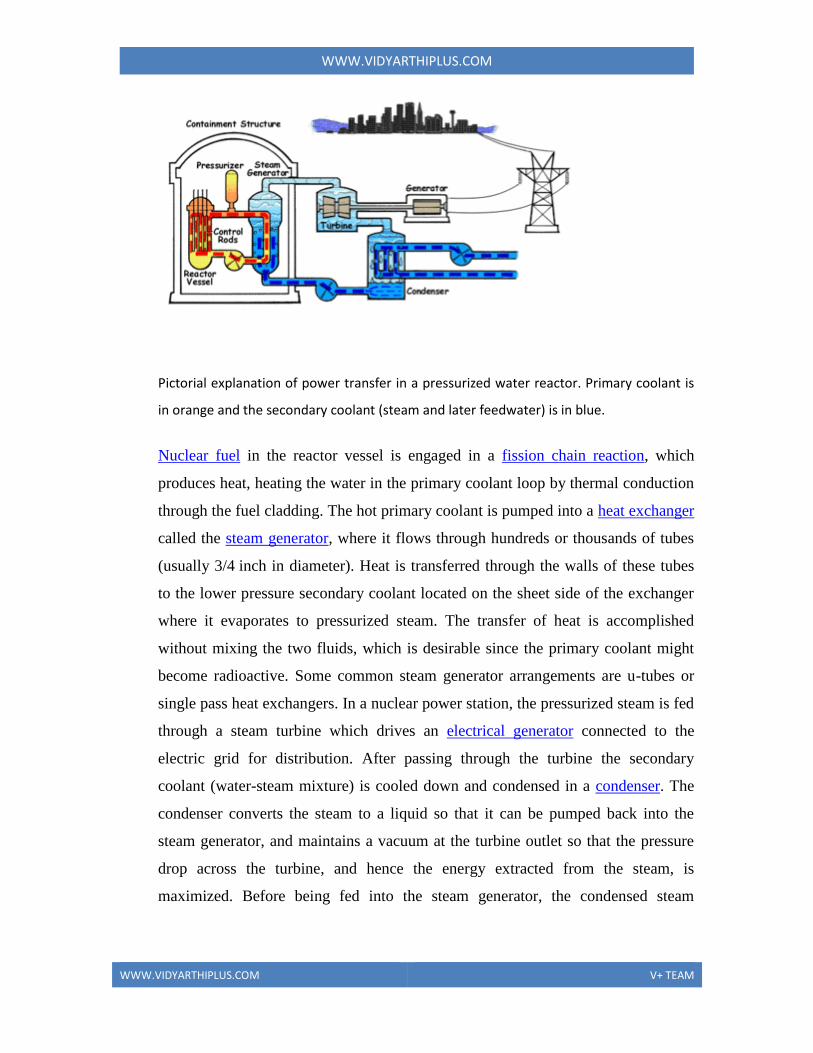

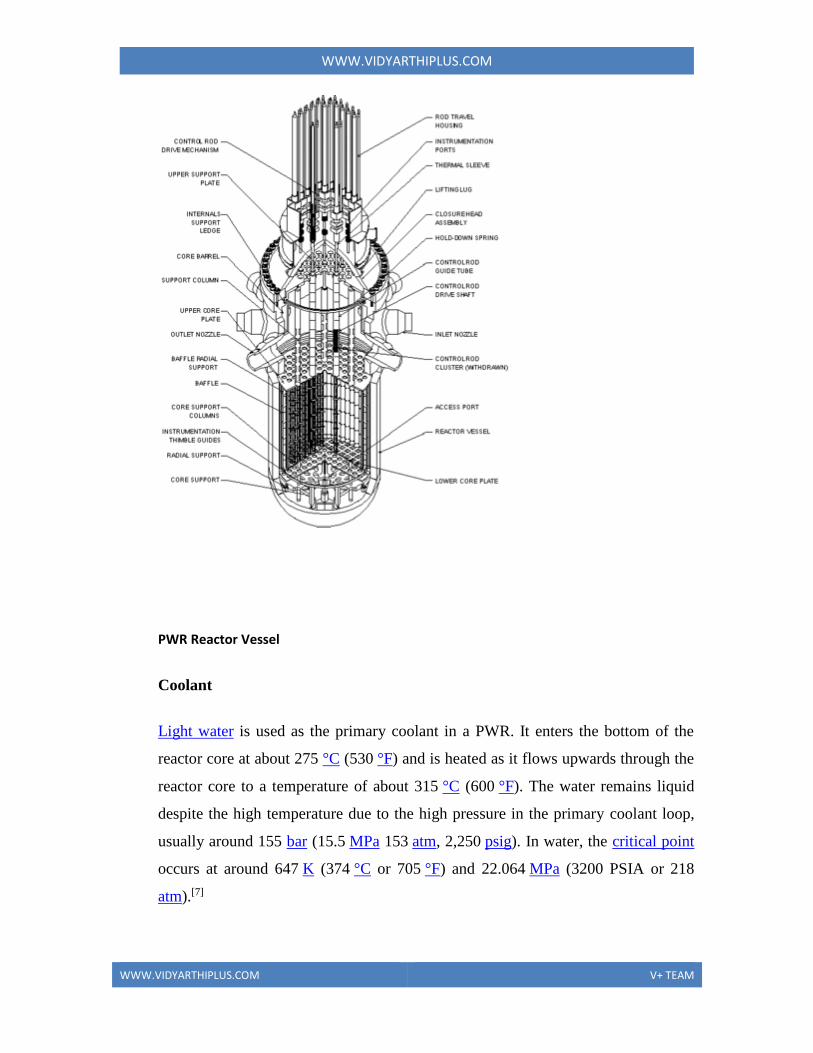


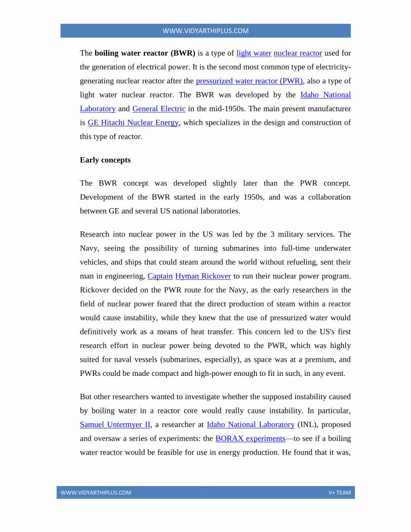
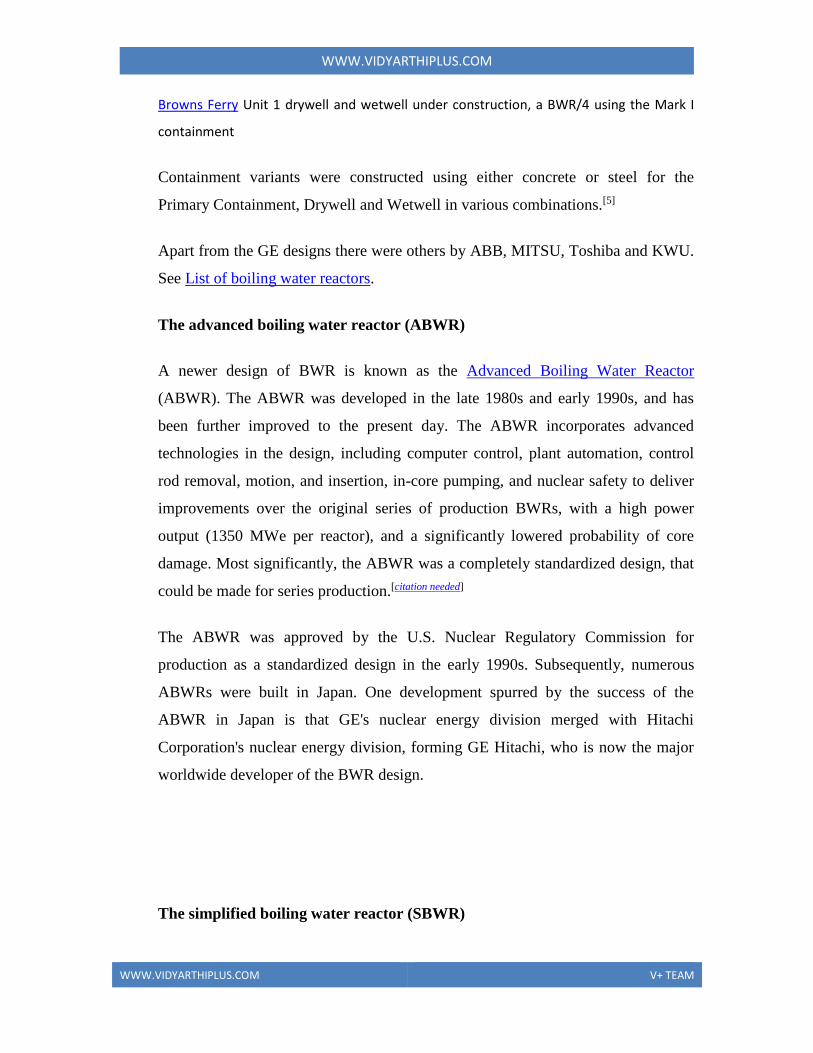


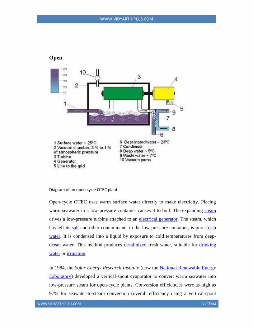


![Welcome [] · 2019-07-24 · Major Job References – Technical Consultancy on Boilers of Thermal Power Plants: RCA and damages Assessment of boiler explosion- Annupur Unit-2, 600](https://img.pdfslide.net/doc/110x75/5e712e7cbcb4e205954506b9/welcome-2019-07-24-major-job-references-a-technical-consultancy-on-boilers.jpg)