Embed Size (px)
Citation preview

UNIT – I
PART – A 1. Write the basic steps in casting process.
➢ Melting the metal ➢ Pouring it into a previously made mould which
confirms to the shape of desired component. ➢ Allowing the molten metal to cool and solidify in
the mould.
2. Write the requirements of a good pattern. (May-2007)
➢ Secure the desired shape and size of the
casting ➢ Simple in design, for ease of manufacture ➢ Cheap and readily available ➢ Light in mass and convenient to handle ➢ Have high strength
3. List the common pattern materials.
➢ Wood ➢ Common metals such as Brass, cast Iron,
Aluminium and white metal etc. ➢ Plastic ➢ Gypsum ➢ Wax
4. State the different types of pattern allowances.
➢ Shrinkage allowance ➢ Machining allowance ➢ Draft allowance ➢ Shake allowance ➢ Distortion allowance
5. What are the different types of sands used in moulds?
Green sand, Dry sand, Loam sand, synthetic sand,
core sand, parting sand, facing sand, backing sand. 6. Name the essential constituents of moulding sand.
Silica sand, Binder, Additives and water.
7. What is core venting?
While pouring the mould with molten metal, mould walls and cores heat up rapidly and give off a large volume of gases. These gases must be vented out through core prints in order to prevent casting defects such as “ Blow holes “.
8. What is core baking?
To impart proper strength to the cores, these are baked or cured in gas, oil or electric ovens. The curing operation drives off the moisture and hardens core binders.

9. Write on the two designs of induction furnaces.
1. Core less or high frequency induction furnace. 2. Core or channel furnace or low frequency induction
furnace.
10. State the different types of moulding machines.
➢ Jolt machine ➢ Squeezer machine ➢ Jolt-squeezer machine ➢ Sand slinger etc
11. Classify the various methods of inspection and testing of castings?
➢ Visual Inspection ➢ Dimensional Inspection ➢ Metallurgical Control ➢ Pressure Testing ➢ Radio-graphical testing ➢ Magnetic testing ➢ Magnetic particle testing ➢ Eddy current Inspection ➢ Ultrasonic testing
12. Define manufacturing.
Manufacturing means the making of goods and articles by hand and or by machinery.
13. Define manufacturing Engineering.
Manufacturing Engineering can be defined as the study of the various processes required to reproduce parts and assemble these into machines and mechanism. 14. Classify the manufacturing processes.
➢ Casting processes ➢ Deformation processes ➢ Machining processes ➢ Powder metallurgy ➢ Joining processes ➢ Heat treatment and surface treatment process
15. What is meant by lost-wax method.
This method involves the use of expandable pattern surrounded with a shell of refractory material to form the casting mould. Casting are formed by pouring the molten metal in the mould cavities created by melting out the pattern. Since the pattern made of wax is melted out and gets destroyed, that is why the name lost-wax method. 16. Write the advantages and disadvantages of lost-
wax method. Advantages :
➢ Intricate shapes can be easily cast. ➢ The surface is very smooth and hence there is
no parting line.

➢ More than one casting can be made at a time. Disadvantages : ➢ Process is involved and thus expensive ➢ Parts are limited in size to few Kg. 17. Write the typical values of Shrinkage allowances
for following metals. i. Brass ii. Steel iii. Zinc iv. Cast Iron
➢ Brass - 15 mm / min ➢ Cast Iron - 10 mm / min ➢ Steel - 20 mm / min ➢ Zinc - 25 mm / min
18. Discuss the advantages and disadvantages of shell moulding.
Advantages :
➢ Complex parts can be made by this method. ➢ High accuracy of castings with tolerances of ±
0.002 to 0.005 mm / mm is possible. ➢ Smooth surface finish and reduced machining
allowance is possible.
Disadvantages : ➢ Size of casting is limited ➢ Carbon pick up in case of steels 19. Discuss the applications of Co2 process. Used for making larger core in Jobbing, Foundries for heavy castings. Suitable for thick walled steel castings. 20. Suggest a furnace to melt grey cast iron. Cupola furnace 21. What is meant by pressure die casting.
- Unlike gravity die casting, in pressure die casting molten metal is forced into permanent mould cavity under pressure.
- Pressure varies from 70 to 5000 kg / cm2. - Pressure is obtained by compressed air (or)
hydraulically.
22. Write the advantages of plastics as pattern material.
- Facilitates the production processes. - Makes it more economical in cost and labour. - No Moisture absorption - Smooth surface of patterns

23. Suggest a pattern which is suitable for casting water pipes, turbines casings etc.
Skeleton pattern 24. Why a colour scheme is needed for patterns?
Illustrate a common colour scheme.
Print of finished part is not furnished with pattern. Many mistakes may be eliminated by indicating the functions of the various parts of the pattern with proper colours. A common colour scheme is given below : Surface as cast - Black Machined surface - Red Core prints and seats - Yellow Loose pieces - Yellow diagonal stripes. 25. Write the chemical reaction involved in Co2
process. The chemical reaction involved in Co2 process is Na2Sio3 +Co2 → Na2Co3 + Sio2
(Sodium (Silicagel ) Silicate)
26. Write the product applications of true centrifugal casting.
- Bearings for electrical motors and industrial
machinery. - Cast Iron Pipes, alloy steel pipes and tubings. - Liners for I.C Engines.
27. Write the advantages of cupola furnace.
- Simple design and easier construction - Low initial cost as compared to other furnaces of
same capacity. - Cupola can be continuously operated for many
hours. - Economy in operation and maintenance.
28. What are the factors should be considered for selecting a furnace for a job?
- Capacity of molten metal - Melting rate and temp armature control desired - Quality of melt required - Method of pouring and types of product
contemplated.
29. What is the aim of Inspection and Testing of castings?
The aim of Inspection and Testing of castings are to prevent defective castings being supplied from the foundry

and to reduce the percentage of inevitable processing rejects. 30. Define pattern.
A pattern is an element used for making cavities in the mould, into which molten metal is poured to produce a casting. 31. What is the difference between green sand mould
and dry sand mould? Green sand mould : A green sand mould is composed of mixture of sand, clay and water. Dry sand mould : Dry sand moulds are basically green sand moulds with 1 to 2% cereal flour and 1 to 2% pitch. 32. What are the casting defects caused by patterns
and molding box equipment.
- Mismatch - Fins, Strain and Flash - Crush
33. What are the casting defects due to improper molding and core making materials.
- Blow holes - Drop - Scab - Pinholes
34. What are the casting defects caused by molding, core-making, gating etc.
- Hot tears - Shifts - Fins and Flash
35. List the types of electric furnaces.
- Direct arc furnace - Indirect arc furnace - High frequency Induction furnace - Low frequency Induction furnace
36. What are the limitations of die casting processes?
- Ferrous alloys are not cast - Maximum size of the casting made by this process
is restricted - This process requires special skills on maintenance
part

37. What is core?
A core is body made of refractory material, which is set into the prepared mould before closing and pouring it for forming through holes, recesses and internal cavities. 38. What are the factors should be considered for
selecting core material?
- Type and size of core - Nature of metal to be cast - Core properties desired - Degree of core surface finish is required
39. What is meant by salvaging of castings?
- Salvaging of castings is done for following reasons - To restore properties and defective casting to a
standard equivalent to that if no defect were present.
PART - B
1. Explain the various types of moulds. According to the material used in their construction, the moulds are of following types:
1. Green Sand Moulds. A green sand mould is composed of a mixture of sand (silica sand, SiO2), clay (which acts as binder and water. The word “green” is associated with the condition of wetness or freshness and because the mould is left in the damp condition, hence the name “green sand mould”. This type of mould is the cheapest and has the advantage that used sand is readily reclaimed. But, the mould being in the damp conditions, is weak and cannot be stored for a longer period. Hence, such moulds are used for small and medium sized castings.
2. Dry Sand Moulds. Dry sand moulds are basically green sand moulds with two essential differences: the sand used for dry sand moulds contains 1 to 2% cereal flour and 1 to 2% pitch, whereas the sand mixture for green sand moulds may not contain these additives increase the hot strength due to evaporation of water as well as by the oxidation and polymerization of the pitch. So, dry sand moulds can be used for large castings. They give better surface finish and also reduce the incidence of the casting defect such as gas holes, blows or porosity that may occur as a result of steam generation in the mould (when the molten metal is poured into the

green sand mould cavity). However, due to the greater strength of these moulds, tearing may occur in hot – short materials.
3. Skin – dry Sand Moulds. Here, after the mould is prepared, instead of entirely drying it out, the mould is partially dried around the cavity (to a depth of about 25mm). This can be done into ways:
(i) About 12.5 mm around the pattern the proper moulding sand (as described under dry sand moulds) is used, the remaining mould contains ordinary green sand.
(ii) The entire mould is made of green sand and then the surface of the cavity is coated with a spray or wash of linseed oil, gelatinized starch or molasses water etc. the advantages and limitations of such moulds are the same as of the dry sand moulds.
4. Loam Sand Moulds. Loam sand consists of find sand plus finely ground refractories, clay, graphite and fibrous reinforcements. If differs from ordinary moulding sand in that the percentage of clay in it is very high ( of the order of 50%). This sand is used in pit moulding process for making moulds for very heavy and large parts (engine bodies, machine tool beds and frames etc.)
5. Cemented – bonded Moulds. Here, the moulding sand contains 10 to 15% of cement as the binder. Such a mould is stronger and harder. Such moulds are made in the pit moulding process and develop their strength by air drying and are used for large
steel casting. However, it is very difficult to break away the sand from the casting.
6. CO2 Moulds. The CO2 moulding process is a sand moulding process in which sodium silicate (Na2O.xSiO2), that is, water glass is used as a binder (2 to 6%), rather than clay. After the mould is made, CO2 gas is made to flow through the mould, the sand mixture hardens due to the following reaction.
Na2O.xSiO2+nH2O+CO2 → Na2 CO3 + x.SiO2.n(H2O)
Stiff gel.
Here, x=1.6 to 4, most often 2.
This reaction is very rapid and takes about 1 minute, which is very much less than the several hours needed to produce a dry sand mould. Such moulds can be used for producing very smooth and intricate castings, because the sand mix has a very high flow ability to fill up corners and intricate conturs.
7. Resin – bonded Sand Moulds. Here, the green
sand mixture is mixed with thermosetting resins (polymers) or an oil, such as, linseed oil or soyabean oil. During baking of the mould, the resin or oil oxidizes and polymerizes around the sand particles, thus bonding them together. The Strength of the polymerized resin is greater than that of pitch used in dry sand moulds. So, the moulds produced are stronger. Such a sand mixture is commonly used for making cores.

Baking is usually needed to make strong moulds or cores. Many times, the required strength of moulds is obtained without banking. These moulds are known as “Furan-no bake” moulds, “oil-no-bake” moulds etc. Furan is a generic term denoting the basic structure of a class of chemical compounds. The resins used in the “no-bake” systems are compounds of furfury1 alcohols, urea and formaldehyde. A very low water content (less than 1%) is used in the above moulds. The synthetic liquid resin is mixed with sand and the mixture hardens at room temperature.
8. Dry Sand Core Moulds. When the moulding flasks are too large to fit in an oven (for baking) or when it costs too much to dry a large mass of sand, moulds are made from assemblies of san cores. A sand core is usually prepared form core sand mixtures (discussed later)and is baked at 175 to 230o C for 4 to 24h, depending upon sand preparation and mass.
2. Explain the various types of moulding machines with neat sketch. The moulding machines are classified as: (i) Squeeze Moulding Machine (ii) Joilt Machines (iii) Sand Sligers
(a) Squeeze Moulding Machines. These machines are operated by compressed air at a pressure from 5 to 7 atm. A schematic diagram of a top squeeze machine is shown in fig. (a). the pattern plate with pattern 2 is clamped on the work table 1 and flask 3 is placed on the plate. Then the sand frame 4 is placed on flask3. The flask and frame are filled with moulding sand from a hopper located above the machine. Next the table lift mechanism is switched on and the flask together with the sand frame and pattern is lifted up against platen 5 of the stationary squeeze head 6. the platen enters the sand frame and compacts the moulding sand down to the upper edge of the flask (shown by a dash line). After the squeeze, the work table returns to its initial position.
The principle of a bottom squeeze machine is shown in fig. (b) the pattern plate 2 with the pattern is clamped on work table 1. flask 3 is placed on frame 7 of the machine and is filled with sand from a hopper. Next, the squeeze head 6 is brought against the top of the flask and the lift mechanism is switched on. Table 1 with plate 2 and the pattern are pushed up to the lower edge of the flask (shown by the dash line). After this the table returns to the initial position.

Fig. Squeeze moulding machine a) and b) Limitation of Squeezing:
1. Sand density is uniform. It is maximum near the plate and then falls gradually towards the pattern. Duet to this, this method is used for work that can be modulated in shallow flasks.
2. If the pattern contains cavities for the formation of green sand cores, squeezing does not make sand flow into the cavities effectively and get it packed property.
(b) Jolt Machine. In the jolt moulding machine, the pattern and flask are mounted on a mould plate and the flask is filled with sand. The entire assembly is raised a small amount by means of an air cylinder and is then dropped against a fixed stop. The compacting of sand is achieved by the decelerating forces acting on it.
Fig. Sand Slinger
The working of a jot moulding machine is shown in fig. the table 1 with moulding sand, is lifted by plunger 4 to a definite height (about 5cm) when compressed air is admitted through pipe 5 and channels6. Next the table drops since the air is released through hole 7. In falling, the table srikes the stationary guiding cylinder 8 and this impact packs the moulding sand in the flask. Springs9, by cushioning the table blows, reduced noise and prevent destruction of the mechanism and the foundation. About 20 to 50 drops are needed to compact the sand, and the average machine operates at about 200 strokes per minute.
The draw back of the method is that the density of
the sand in the mould is not uniform. It is greatest in the layers next to the pattern plate and lowest near the top of the mould, because in the course of impact, every upper layer acts on the lower layer. Also, there is high level of noise produced by the jolt machines in operation and there is considerable load on the foundation. Sand Slingers: In these machines, the sand is thrown out by centrifugal force from a rapidly rotating single bladed impeller and directed over the pattern in the flask. This type of compaction results in mould having a more uniform density throughout, than does the squeezing or jolting method. These machines can fill flasks of any size, but are generally used only in the making of large moulds. They can be efficiently employed in both mass and piece production. These machines operate with a high output; one sand slinger can fill flasks, packing the sand, at a rate of 60 m3 per hour. The disadvantage of the machine is that

it doe not draw the pattern or handle the mould in any may.
The principle of operation of the impeller head on the sand slinger is shown in fig. the head consists of housing in which blade rotates rapidly. Moulding sand is fed by a belt conveyer to opening in the end face of the housing where it is picked up by blade and thrown in separate portions at a high speed through outlet down into the flask under the head. 3. Discuss the various pattern allowances in detail? 1. Shrinkage Allowance. Since metal shrinks on solidification and contracts further on cooling to room temperature, linear dimensions of patterns are increased in respect of those of the finished casting to be obtained. This is called the “shrinkage allowance”. It is given as mm/m. Typical value of shrinkage allowance for various metals are given below:
CI, Mallcable iron = 10mm/m
Brass, Cu, A = 15mm/m Steel = 20mm/m Zinc, Lead = 25mm/m
While laying out a pattern, the dimensions are taken from a pattern maker’s rule, called “Shrink scale”, which is longer than a standard scale by the shrinkage value for the appropriate metal. 2. Machining Allowance. Machining allowance or finish allowance indicates how much larger the rough casting should be over the finished casting to allow sufficient material to insure that machining will “clean up” the surfaces. This machining allowance is added to all surfaces that to be machined.
The amount of finish allowance depends on the material of the casting, its size, volume of production, method of moulding, configuration of the casting, the position the wall surface occupies in the mould and during poring. Machining allowance is larger for hand moulding as compared to machine moulding. The largets allowances are taken for the surfaces located in the cope half of the mould, since they are liable to contamination duet to slag. Typical machining allowances for sand casting are given in Table the allowances are in mm per side. For internal surfaces such as bores, the allowance is about 0.8 mm greater and is negative. 3. Pattern draft or Taper. Pattern draft also termed is “drawn” is the taper placed on the pattern surfaces that are

parallel to the direction in which the pattern is withdrawn from the mould (That is perpendicular to the parting plane). To allow removal of the pattern without damaging the mould cavity, fig. (a). The draft depends upon the method of moulding, the common draft is 10 to 30 After applying the draft, the largest cross- section of the pattern will be at the parting line for external surfaces and reverse will be for internal surfaces, (fig. (b). (a) (b) Pattern Taper.
4. Corners and Fillets. The intersection of surfaces in casting must be smooth and form no sharp angles. For this, the external and internal corners of patterns are suitably rounded. They are called rounded corners and fillets respectively. Fillets facilitate the removal of the pattern from the mould, prevent the formation of cracks and shrink holes in the casting. The radius of a fillet is
given as =1 1
to5 3
(arithmetic mean of the thickness of the
two walls that form the angle in the pattern). 5. Rapping or Shake Allowance. To take the pattern out of the mould cavity it is slightly rapped to detach it from the mould cavity. Due to this, the cavity in the mould increases slightly. So, the pattern is made slightly smaller. 6. Distortion Allowance. This allowance is considered only for castings of irregular shape which are distorted in the process of cooling because of metal shrinkage. 4. What are the different types of pattern? Explain any five with neat sketch. Split or Parted Pattern. These patterns are split along the parting plane (which may be flat or irregular surface) to facilitate the extraction of the pattern our of the mould before the pouring operation. Moulding with a split pattern has already been explained under Art. 2.2.4, Fig (a) shows a split pattern for casting a bush. The two parts of the pattern are joined together with the help of dowel pins. For a more complex casting, the pattern may be split in more than two parts.

Loose Piece Pattern. When a one piece solid pattern has projection or back drafts which lie above or below the parting plane, it is impossible to with draw it from the mould. With such patterns, the projections are made with the help of lose pieces. A loose piece is attached to the main body of the pattern by a pin or with a dovetail slide. While moulding, sand is rammed securely around the loose piece. Then the pins are removed. The sand is then packed and rammed around the total pattern. When the main pattern is drawn, the loose pieces remain in the mould. These are then carefully rapped and drawn as shown in fig. (b). One drawback of loose pieces is that their shifting is possible during ramming. Draw backs. Another technique to make a mould with a one piece solid pattern (with projections) is the use of drawbacks. A draw back is a portion of the mould, which can be drawn back horizontally in order to allow removal of the pattern. It may be rammed around a rigid support called an “arbor” to facilitate moving it, (fig. ©).

Gated Patterns. A gated pattern is simply of or more loose patterns having attached gates and runners. (fig. (d)). Since the gates and runners are not to be cut by hand, gated patterns reduce the moulding time somewhat. Because of their higher cost, these patterns are used for producing small castings in mass production systems and on moulding machines. Match Plate pattern. A match plate pattern is a split pattern having the cope and drag portions mounted on opposite sides of a plate (usually metallic), called the “match plate” that conforms to the contour of the parting surface. The gats and runners are also mounted on the match plate, (fig (e)), so that very little hand work is required. This results in higher productivity. This type of pattern is used for a large number of castings. Several patterns can be mounted on one match plate if the size of the casting is small. The patterns need not all be for the same casting. When match plate patterns are used, the moulding is generally done on a moulding machine. Piston rings of I.C. engines are produced by this process. Cope and Drag Pattern. A cope and drag pattern is a split pattern having the cope and drag portions each mounted on separate match plats. These patterns are used when in the production of large castings, the complete moulds are too heavy and unwidely to be handled by a single worker. The patterns are accurately located on the plates, so that when the two separately made mould halves are assembled together, the mould cavity is properly formed. For a higher rate of production, each half of the pattern is mounted on a separate moulding machine, one operator
working on the cope part of the mould and the other on the drag part of the mould. Sweep Patterns. A sweep is a section or board (wooden) of proper contour that is rotated about one edge to shape mould cavities having shapes of rotational symmetry, (Fig. (f)). This type of pattern is used when a casting of large size is to be produced in a short time. A complete pattern is not necessary and would be very expensive for a very large casting where the tolerances are large. The moulds are made manually, either in a pit or on the foundary floor. Thus, this type of moulding is referred to as pit and floor moulding. The moulding sand used is the “loam sand”. A frame work of brick or wood supports the loam. Once the mould is ready, the sweep pattern and the spots about which it rotates, are removed before pouring the mould cavity. Large kettles of C.I. are made by sweep patterns. 5. Explain the various properties of moulding sand in detail?
1. Permeability. Permeability or porosity of the moulding sand is the measure of its ability to permit air to flow through it.
Molten metal always contains a certain amount of
dissolved gases which try to leave it when the metal solidifies. Also, when the mould is poured, water vapours and other gases are generated when the molten metal comes in contacts with the moulding sand and the cores. If all these gases and vapours are not able to escape completely through the walls of the mould, they may

penetrate the liquid metal where, after solidification, they form gas holes and pores. To avoid these defects, the moulding sand should have good gas permeability.
Permeability of the moulding sand is influenced by : quality and quantity of clays and quartz in the mixture, moisture content, degree of compaction etc. the higher the percentage of silica content of a moulding sand mixture ( that is lower clay content), the better its permeability and vice versa. The larger the grain size, the better its permeability and vice versa. The distribution of grain size in a particular sand mix, greatly influences the permeability. If all the sand particles in a mix are of the same size. then the bulk density is low and the permeability is higher because of the voids between the sand particles. Angular grains that are randomly oriented will have a lower bulk density than spherical gains and thus higher permeability. A sand mixture containing grains of all sizes, from the largest that can be used to the smallest ones, will have a bulk density approaching the true density of the and. In this case, the permeability of the mixture will be very low, because the smaller particles will fill up the interspaces of bigger grains.
A gain, higher the silt content of sand, the lower its gas permeability. If the mould is rammed too hand, its permeability will decrease and vice versa.
2. Strength or Cohesiveness. It is defined as the property of holding together of sand grains. A moulding sand should have ample strength so that the mould does not collapse or get partially
destroyed during conveying, turning over or closing. This property also enables the pattern to be removed without breaking the mould and to stand the flow of molten metal when it rushes inside the mould. Also, when the mould cavity is filled with molten metal, its bottom and walls are subjected to a high metallostaic pressure. If the sand is not strong enough to resist this pressure, the mould cavity gets enlarged and the castings obtained are oversize.
Strength of the moulding sand depends on the gain
size and shape of sand particles, moisture content and density which varies with the content of clay binders in the sand mixture. The strength of the moulding sand grows with density, clay content of the mix and decreased size of sand grains. So, it is clear that as the strength of the moulding sand increases, it s porosity decreases. 3. Refractoriness. It is the ability of the moulding
sand mixture to withstand the heat of melt without showing any sings of softening or fusion. This property is greatly influenced by the purity of the sand particles and their size. It increases with the grain size of sand and its content and with the diminished amount of impurities and silt.
4. Plasticity or flowability. It is the measure of the moulding sand to flow around and over a pattern during ramming and to uniformly fill the flask this property may be enhanced by adding clay and water to the silica sand.

5. Collapsibility. This is the ability of the moulding sand to decrease in volume to some extent under the compressive forces developed by the shrinkage of metal during freezing and subsequent cooling. This property is especially important for cors. This property permits the moulding sand to collapse easily during shake out and permits of the core to collapse easily during its knockout form the cooled casting. Lack of collapsibility in the moulding sand and core may result in the formation of cracks in the casting. This property depends on the amount of quartz sand and binder and their type.
6. Adhesiveness. This is the property of sand mixture to adhere to another body (here, the moulding flasks). The moulding sand should cling to the sides of the mooulding boxes so that it does not fall our when the flasks are lifted and turned over. This property depends on the type and amount of binder used in the sand mix.
7. Co-efficient of Expansion. The sand should have low co-efficient of expansion.
6. Discuss the different moulding sand test procedures. The following tests have been recommended by B.I.S. 1. Moisture content test 2. Clay content test 3. Permeability test 4. Fineness test or Sand grain size test (Sieve analysis) 5. Strength test 6. Mould hardness test.
1. Moisture content test: Moisture is an important constituent of moulding sand. Its content in the moulding sand can be estimated as given below:- (a) By the loss of weight after evaporation: Test sample is carefully weighed 50gm of moulding sand. It is heated for 2 hours at 105oC to 110oC. It is then allowed to cool to room temperature on a desicator, after which it is reweighed. The difference in weight divided by the weight of the sample (50gm) and multiplied by 100 gives the percentage moisture content. (b) By Moisture teller:- In this method, the sample is placed on the teller pan which has 500 mesh screen in the bottom. Hot air is blown through the sand. Moisture gets removed in only about 5 minutes and so the method is quite fast. The sand sample is weighed directly in the teller pan and the loas in weight is accordingly determined. (C) By moisture teller based on chemical reaction: In this method, a measured weight of sand (10gm) in a cap is placed in the moisture teller along with a container containing a measured amount of CaC2(sand and CaC2 should not come into contact with each other). The reactions of CaC2 with moisture in the sand will produce C2H2, CaC2+2H2O → C2H2+Ca(OH)2
The amount of C2H2 produced is proportional to the content of moisture in the sand. The moisture content is

directly measured from a calibrated scale on the instrument. 2. Clay content test: Under this test, the clay content is measured by washing it off the sand sample. The standard dried sand sample (50gm) is put in a mixing device along with distilled water and 1% NaOH solution. The mixture is stirred for 5 minutes and is then allowed to settle for 10 minutes. The operation is repeated until the water above the sand in the mixer is clean. This water is drained off. The sand is dried and weighed. The loss of weight gives the clay content. 3. Permeability test: As already defined, permeability or porosity of the moulding sand is the measure of its ability to permit air to flow through it. It is measured in terms of “Permeability number.” In this test, a test specimen of
moulding sand (50.8 mm dia. 50.8mmlong) is placed in a tube. Time taken for 2000 cm3 of air at a pressure of 10gm/cm2 to pass through the specimen is noted. Then, the permeability number is given as:
V h
Pp A t
=
where, P=Permeability number V=Volume of air passing through test specimen H=Height of specimen P= pressure of air A=Cross – sectional area of specimen T= time taken by air to flow through the specimen
Understand conditions the formula becomes
( )
( )
2
2000 5.08 P
10 5.08 t4
50.128 = it is minutes
t
501.28or P=
p t
=
4. Fineness Test: Fineness test of the sand specimen determines the size of grains and the distribution of grains of different sizes in the moulding sand. Their effect on the properties of moulding sand has been discussed in Art. The test is performed on completely dry and clay the coarsest sieve at the top and the finest sieve at the bottom, next to the pan. The sand is put in the top sieve and the set of sieve is shaken continuously for 15 minutes with the help of an electric motor. At the end of shaking operation, the sieves are taken our and the sand retained on each is carefully weighed. Each weight is converted to a percentage basis. Each percentage is multiplied by a weighting factor and these are added to get the sum of products. Then the grain fineness number (GFN) is given as,
sum of productsGFN
Sum of percentages of sand retained on each sieve and pan=
As per AFS (American Fondrymen’s Society), the
various sievemesh numbers and the corresponding weighting factors (multiplying factors) are given below:
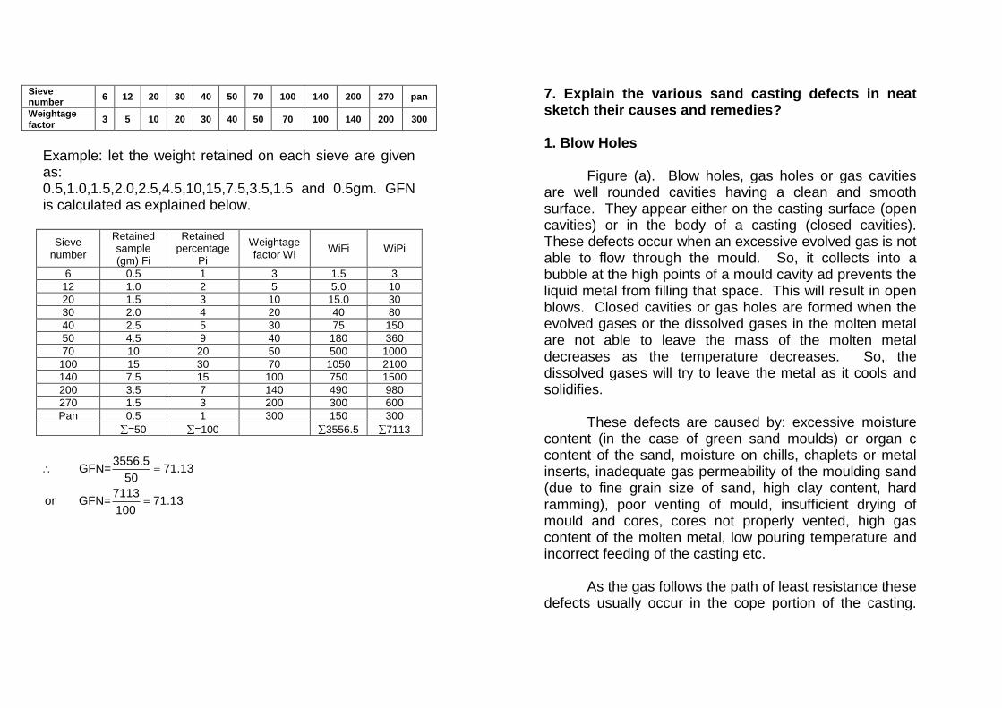
Sieve number
6 12 20 30 40 50 70 100 140 200 270 pan
Weightage factor
3 5 10 20 30 40 50 70 100 140 200 300
Example: let the weight retained on each sieve are given as: 0.5,1.0,1.5,2.0,2.5,4.5,10,15,7.5,3.5,1.5 and 0.5gm. GFN is calculated as explained below.
Sieve number
Retained sample (gm) Fi
Retained percentage
Pi
Weightage factor Wi
WiFi WiPi
6 0.5 1 3 1.5 3
12 1.0 2 5 5.0 10
20 1.5 3 10 15.0 30
30 2.0 4 20 40 80
40 2.5 5 30 75 150
50 4.5 9 40 180 360
70 10 20 50 500 1000
100 15 30 70 1050 2100
140 7.5 15 100 750 1500
200 3.5 7 140 490 980
270 1.5 3 200 300 600
Pan 0.5 1 300 150 300
=50 =100 3556.5 7113
3556.5
GFN= 71.1350
7113or GFN= 71.13
100
=
=
7. Explain the various sand casting defects in neat sketch their causes and remedies? 1. Blow Holes
Figure (a). Blow holes, gas holes or gas cavities are well rounded cavities having a clean and smooth surface. They appear either on the casting surface (open cavities) or in the body of a casting (closed cavities). These defects occur when an excessive evolved gas is not able to flow through the mould. So, it collects into a bubble at the high points of a mould cavity ad prevents the liquid metal from filling that space. This will result in open blows. Closed cavities or gas holes are formed when the evolved gases or the dissolved gases in the molten metal are not able to leave the mass of the molten metal decreases as the temperature decreases. So, the dissolved gases will try to leave the metal as it cools and solidifies.
These defects are caused by: excessive moisture content (in the case of green sand moulds) or organ c content of the sand, moisture on chills, chaplets or metal inserts, inadequate gas permeability of the moulding sand (due to fine grain size of sand, high clay content, hard ramming), poor venting of mould, insufficient drying of mould and cores, cores not properly vented, high gas content of the molten metal, low pouring temperature and incorrect feeding of the casting etc.
As the gas follows the path of least resistance these defects usually occur in the cope portion of the casting.

Internal gas holes are revealed when the casting is machined or cut into sections. 2. Misrun or Short run
This defect is incomplete cavity filling, (figure (b)). The reasons can be: inadequate metal supply, too low mould or melt temperature, improperly designed gates, or length to thickness ratio of the casting is too large. When molten metal is flowing form one side in a thin section, it may loose sufficient heated resulting in loss of its fluidity, such that the leading edge of the stream amy freeze before it reaches the end of the cavity. This defect determines the minimum thickness that can be cast for a given metal, superheat, and type of mould. 3. Cold Shut
A cold shut figure (c) is an interface within a casting that is formed when two metal streams meet without complete fusion. The causes are the same as for misrun. 4. Mismatch
Mismatch is a shift of the individual parts of a casting with respect to each other. This may occur due to mould shift or core shift, (figure (d)). The causes can be an inexpert assembling of the two halves of the mould, from wear of pin bushes and pins and dimensional discrepancy between the core prints of the pattern and the core prints of the core.
5. Flashes
Flashes or Fins commonly appear along the mould joint at the places where the mould halves do not fit together properly because of much wear or warping of flask halves or improper fastening of the cope to the drag. 6. Metal Penetration
or burnt on sand is a strong crust of fused sand on the surface of a casting which results from insufficient refractoriness of moulding materials, a large content of impurities, inadequate mould packing and poor quality of mould washes. When the molten metal is poured into the mould cavity, at those places when the sand packing is inadequate, some metal will flow between the sand particles for a distance into the mould wall and get solidified. When the casting is removed, this lump of metal remains attached to the casting. Of course, it can be removed afterwards by chipping or grinding.

Figure: Casting Defects 7. Drop
Drop or crush in a mould is an irregularly shaped projections on the cope surface of a casting (figure (e)). This defect is caused by the break away of a part of mould sand as a result of weak packing of the mould, low strength of the moulding sand, malfunctioning of moulding equipment, strong jolts and strikes at the flask when assembling the mould. The loose sand that falls into the cavity will also cause a dirty casting surface, either on the top or bottom surface of the casting depending upon the relative densities of the sand and the liquid. 8. Run out
Run out is the defect of metal leaking out of the mould during pouring. This defect occurs due to faulty moulding and faulty flask equipment.

9. Cut or Wash
A cut or wash is a low projection on the drag face of a casting that extends along the surface, decreasing in height as it extends from one side of the casting to the other end. It usually occurs with bottom gating castings in which the moulding sand has insufficient hot strength, and when too much metal is made to flow through one gate into the mould cavity, figures (f). 10. Scars and Blisters
A scare is a shallow blow. It generally occurs on a flat surface, whereas a blow occurs on a convex casting surface. A blister is a shallow blow like a scar with a thin layer of metal covering it, figure (g.h). 11. Hard Spots
This defect occurs only with certain metals such as gray C.I. with insufficient silicon. Such metals may become hardened by the chilling effect of moulding sand. Hard spots will cause difficulty if the castings are to be machined. 12. Pinhole Porosity
Pin holes are small gas holes either at the surface or just below the surface. When these are present, they occur in large numbers and are fairly uniformly dispersed over the surface. This defect occurs due to gas dissolved in the alloy and the alloy not properly degassed.
13. Shrinkage Cavities
A shrinkage cavity is a depression or an internal void in a casting that results from the volume contraction that occurs during solidification. Its causes and remedies have already been discussed. 14. Hot Tears
Hot tears (figure (i)). Are hot cracks which appear in the form of irregular crevices with a dark oxidized fracture surface. They arise when the solidifying metal does not have sufficient strength to resist tensile forces produced during solidification. They occur chiefly from an excessively high temperature of casting metal, increased metal contraction, incorrect design of the gating system and casting on the whole (causing portions of the casting to be restrained from shrinking freely during cooling which in turn causes excessive high internal resistance stresses), poor deformability of the cores, and non-uniform cooling which gives rise to internal stresses. This defect can be avoided by improving the design of the casting and by have in a mould of low hot deformation. 15. Sponginess
Sponginess or honeycombing (figure (j) is an external defect, consisting of a number of small cavities in close proximity, which usually come through and are apparent on the surface. It is caused by ‘dirt’ or ‘inclusions’ held mechanically in suspension in molten metal and is due to imperfect skimming of slag in the ladle

and incorrect gating design. The impurities being lighter than the metal rise to the upper part of the cavity, often accompanied by bubbles of gas if the venting is not proper. 16. Scab
This defect occurs when a portion of the face of a mould lifts or breaks down and the recess thus made is filled by metal (figure (k). When the metal is poured into the cavity, gas may be disengaged with such violence as to break up the sand (sand up heaving), which is then washed away and the resulting cavity filled with metal. The reasons can be:- too fine a sand, low permeability of sand, high moisture content of sand, and uneven mould ramming. 17. Swell
A swell is a slight, smooth bulge usually found on vertical faces of castings resulting from liquid metal pressure figure (l). It may be due to low strength of mould because of too high a water content or when the mould is not rammed sufficiently. 8. Explain the following in details the working Principles. 1. True Centrifuge Casting. 2. Semi-Centrifuge Casting. True-Centrifugal Casting: True centrifugal castings are produced by pouring molten metal into the cavity of a rapidly rotating metal mould to whose walls the metal is
thrown by centrifugal force and where it solidifies in the form of a hollow casting. Thus the distinguishing feature of true-centrifugal casting is the production of hollow casting by the centrifugal force alone and without the aid of a central core.
The centrifugal casting machines used to spin the mould may have either a horizontal or a vertical axis of rotation. For short castings, that is, when diameter to length ratio is rather large (bronze bushings, worm wheels and piston ring blanks), the rotational axis is vertical. Long parts, that is, castings with relatively long length in relation to their diameters (C.I. water supply and sewerage pipes, steel gun barrels etc.) are made in horizontal axis machines.
The principle of the vertical axis machine is shown in Figure (a). As is clear, the central hole will not be completely cylindrical, but will be slightly paraboloidal, which will need machining after the casting is made. However, nearly cylindrical holes can be made by employing higher spinning speeds. The moulds may be permanent moulds made of metal or graphite or may be sand lined.
There are two types of horizontal axis centrifugal casting machines which differ in the way the metal is distributed along the length of the mould during pouring: In one, the pouring trough (ladle or spout) travels horizontally, while the spinning mould is stationary. In the other type, the ladle is stationary and the mould travels. The mould or flask is made of steel or graphite. The metal

mould can be used as it is or its inner surface may be lined with green sand or dry sand. The choice depends upon the geometrical dimensions of a casting, its material and the production volume. Metal moulds are preferred for the production of a large number of single-type parts which show no retarded shrinkage and have an outer shape allowing easy extraction of the casting from the mould. Sand-lined moulds are preferred for castings in which retarded shrinkage moulds. Such moulds are used to advantage for the production of a small lot of cast iron pipes without chilling. These pipes will not require annealing heat treatment, as will be needed for similar pipes made in metal moulds, since the cooling rate will be slow because of sand lining. The sand lining also protects the metal mould from the intense heat of the molten metal and, increases its durability.
The method of casting pipes in which the ladle is stationary and the mould travels is called as “The deLavaud Process”. This is explained with the help of the following steps, (see Figure (b)),: 1. The machine consists of an accurately machined metal mould surrounded by water. Dry heat-insulating coats (refractory mould wash of materials such as quartz sand and phosphate flour) are applied to the inner surface of the mould to secure stable thermal conditions, increase its durability and produce iron castings free of chill. The machine is mounted on wheel so that it can be moved lengthwise on a track.
Figure a : True Centrifugal Casting.

2. The metal mould is heated to 150 - 200C before pouring. After pouring, the mould is cooled to by circulating water through the surrounding shell. 3. The long pouring spout is inserted to the far extremity of the mould. 4. As pouring proceeds, the rotating mould, that is, the machine is moved slowly on the track, leftwards. 5. At the end of the process, the machine will be at the lower end of its track, with the mould spinning continuously till the pipe has solidified. 6. The cast pipe is then extracted from the mould by inserting a piper puller.
The use of the sand head core is to form the inside contour of the bell end of the pipe. If desired, the outer contour of the casting can be varied, while the inside remains cylindrical. The spinning speed of the mould will depend upon the diameter of the pipe, the composition of the pouring metal and a number of other factors. Advantages:
1. Castings acquire high density and are distinguished for their fine-grained structure and high mechanical strength.
2. Inclusions and impurities such as oxide, slag and gas etc., being lighter than the molten metal, will segregate toward the centre and cling to the inside
surface of the casting where they may be removed by subsequent machining operations.
So, the castings will be of mainly clean metal.
3. Gates and risers are not needed, which results in saving in material and increasing the yield.
4. High output. 5. Formation of hollow interiors without cores. 6. The castings are less subject to directional
variations than static castings. Disadvantages:
1. Contaminations of inner surface of the casting with segregates and non-metallic inclusions, which make it necessary to increase finishing allowance for subsequent machining of inner surfaces.
2. An inaccurate diameter of the inner surface of a casting.
3. Not all the alloys can be cast by this method due to the increased segregations of alloy constituents during pouring under centrifugal forces.
Product applications: Parts with rotational symmetry: C.I. water supply and sewerage pipes, steel gun barrels, pump components, rolls, liners, hollow shaftings, bearings, sleeves, hydraulic jack cylinders and air cylinders, large propeller shaft sleeves and stern tubes, chemical reactor vessels, heat exchanger bodies, refinery and petrochemical applications; pressure vessel bodies, reactor tubes and pressure piping for nuclear power plants

; paper mill rolls, textile rolls, steel mill rolls and machinery drive rolls etc. Figure: Semi-centrifugal Casting. Semi-centrifugal Casting: When the moulds prepared by any of the techniques under expendable or permanent moulds are rotated about the central vertical axis and the casting is symmetrical about the axis of rotating (that is the axis of the casting coincides with the axis of rotation), the process is called as “semiconductor-centrifugal casting”. The centrifugal force aids the flow of the molten metal from a central feeding sprue and can thereby produce a somewhat more dense structure as compared to conventional sand casting, (Figure). Casting shapes can be more complicated than true centrifugal casting. Cores are used if central hole is needed, the spinning speed being considerably less than that for true centrifugal casting. An advantage of the process is that stack moulding can be used to cast many parts at the same time.
Product applications: Disk shaped parts: Wheels, rings, rollers, sheaves, pulleys, flywheels, gear blanks, Turbo-Supercharger diaphragm disks and steel railroad wheels etc. 9. Explain the Lost wax method and the steps involved in it. Lost-wax method: The lost-wax method, sometimes, also called simply as ‘precision-investment casting’ has been used for many years by jewelers and dentists. Since world-war-II, the method has been adapted to the production of small and precise industrial castings. Basically, the method involves the use of expendable (heat disposable) pattern surrounded with a shell of refractory material to form the casting mould. Castings are formed by pouring molten metal in the mould cavities created by melting out the pattern. Since the pattern made of wax is melted out and gets destroyed, that is, why the name “lost-wax method”. The steps involved in this method are explained below:
1. Making a master pattern of the part to be cast. The pattern is usually made of a metal that can be easily machined, such as, brass, aluminium alloy or steel, or a fusible alloy (alloy of tin, lead and bismuth). It is made oversize to compensate for wax and metal shrinkage.
2. Making a composite die to the master pattern (by casting) for casting the wax/plastic patterns. The die-material is a low melting-point alloy like bismuth alloys or even aluminium and C.I. The master dies

can be directly made from die-blocks of steel by machining the cavities.
3. Making of wax / plastic patterns For this, the two halves of the master die are clamped together and molten wax/plastic is injected into the die cavity under pressure, Figure (a)). The molten wax is slightly above its melting point and the injection pressure is about 4 bars with the dies preheated to about 65oC. For plastic materials (polystyrene, polythenes etc.), the injection pressure is of the order of 35 bars with higher temperature.
4. Assembling the wax patterns to a wax gating system. Several small wax patterns are assembled together to a wax gating system connected to a central sprue, by wax welding with the aid of heated tools. In this manner, a cluster or “tree” of wax patterns is formed, (Figure (b)).
5. Investing the wax patterns. The wax patterns are invested in two stages. Firstly, a thin coating (about 1 mm) of primary investment slurry is made around the wax patterns by dipping these in the slurry. This slurry is made by mixing extremely fine silica sand with a water/ethyl silicate or gypsum solution. This slurry coating being in direct contact with the surfaces of the wax patterns, will determine the surface quality of the castings. After this primary coating has dried sufficiently, the final investment layer consists of coarser and less expensive slurry. The final investment moulds may be either solid type or shell type. A solid type mould is formed by placing a metal container type flask over the cluster of patterns and then pouring a hard-setting
moulding materials into the flask, (Figure (c). Shell type investment moulds are made by dipping the cluster of patterns in a ceramic slurry and the procedure is repeated until the required thickness of the mould or shell (about 6.5 mm) is obtained. The common refractory used for investment material is silica. The binder is gypsum or water-based sodium silicate.
Figure: Lost wax Method.

6. Melting out the wax patterns and baking the mould. The finished mould is dried in air for 2 to 3 hours and then baked in an oven for 2 hours to melt out the wax. At a temperature of 100 to 120oC the wax melts and the moulds are inverted so that all or most of the wax will run out of the sprue.
7. Melting the metal and pouring the mould. The mould or flask is transferred to a drying furnace where it is first held at 150oC and then gradually heated to 800 to 900oC. This will vaporize any remaining wax in the mould. The preheated mould also ensures that the molten metal will completely fill the mould cavity. The preheated mould is poured with molten metal which fills the cavity and is allowed to cool and solidify. Another way to fill the cavity is to place the mould on a vacuum table and drawing a vacuum though the slurry which will help suck the metal right into the mould or by placing the mould in a centrifugal casting machine and pouring the metal in this manner.
8. Shaking out the castings, removing gates and feeders. After cooling, the fragile mould material is broken away freeing the castings. The gates and runners are removed in the normal way.
9. Cleaning and inspecting the casting. Advantages of Lost – wax method: (i) Intricate details can be cast. (ii) Undercuts and other shapes, which would not
allow the withdrawal of a normal pattern, are easily obtained.
(iii) The surface is very smooth (1.5 to 2.25 m Ra) and there is no parting line.
(iv) High accuracy can be obtained (tolerances of
the order of 0.003 mm/mm can be obtained) so that much of complicated and costly machining can be eliminated.
(v) Unmachinable alloys (heat resisting steels or nimonic alloys) can be cast.
(vi) More than one casting can be made at a time. Limitations:
(i) The process is involved and thus expensive. (ii) The process has the limitations in use of and
location of holes. (iii) The parts are limited in size to a few kg.

10. Explain the various steps involved in shell moulding process? P-97
Shell Moulding: The process involves the use of match plate patterns similar to cope and drag patterns which are used for green sand casting. The process is based on the capability of a thermosetting resin and sand mixture to assume the shape of a preheated metal pattern and to form a dense, quickly hardened shell mould. The two matching shell halves (made from cope and drag parts of the pattern) are clamped or glued together to form the mould cavity. Castings are obtained by pouring molten metal into this mould cavity. The shell thickness varies from 5 to 8 mm. As in sand casting process, the mould is expendable and must be broken away to facilitate the removal of the solidified casting. Shell moulding process involves the following steps: 1. Preparation of the metal match plate cope and drag type patterns: The patterns are machined from copper alloys, C.I., Al or Steel depending upon the life of the pattern. They are given the usual shrinkage and draft allowances, are polished and then attached to the metal match plates. 2. Mix the investment material: The investment material consists of dry, fine and thoroughly washed silica and 5 to 10% of thermosetting phenolic resin (phenol formaldehyde) which acts as a binder. The two are thoroughly mixed together.
3. Heat the pattern: The pattern plate is heated to about 200 to 300oC for investing it. To prevent/minimize the mould adhesion of the

investment material and to make the removal of the shell convenient, a release agent containing a silicone is next sprayed over the hot pattern plate surface.
4. Invest the pattern: For this, the investing material
is placed in a container called “dump box” (about one-third full) and the heated pattern plate is clamped to it, with the pattern surface inwards. The dump box is then quickly inverted on its trunnions. The investing material falls over the surface of the heated pattern. The heat penetrates the mixture, softens the binder making it effective. This will result in the formation of a uniform shell around the pattern surface after the binder thermosets. The shell thickness will depend upon the time of contact of the mixture with the heated pattern. In about 30 to 45 s, we can get a normal shell thickness of 5 to 8 mm. The dump box is then rotated back to its normal position. The loose and unaffected investing mixture will fall down, leaving the shell adhering closely to the pattern.
5. Curing the Shell: For this, that is, to cure or harden the shell, the pattern plate is removed from the dump box and transferred to an oven and cured for about 1 to 3 minutes at a temperature of about 250 to 450oC.
6. Remove the Shell: The shell is then stripped from
the pattern plate with the help of a number of ejector pins which pass through the plate. When these ejector pins are pressed simultaneously, the
tops of these pins at the pattern plate surface, more upward and strip the shell from the pattern plate.
7. Repeat the steps 2 to 6 for the other half of the metal match plate pattern to produce the other half of the shell.
8. Assemble the Shells: The two halves of the cured shells are securely assembled by clamping or bonding them together at the parting line with a quick-acting thermosetting resin adhesive such as phenol-formaldehyde.
9. Pour the Mould: It is done in the same manner as for Lost-wax method that is static pouring or vacuum pouring or centrifugal pouring.
10. Remove the Casting: After cooling and solidification, the shells are broken or shaken away from the castings in the usual way. The steps are clear in Figure
Advantages:
1. A high precision/accuracy of castings with
tolerances of 0.002 to 0.005 mm/mm, is possible. 2. Smooth surface finish and reduced machining
allowances possible. Many shell mould castings require almost no subsequent machining. The common value of surface roughness is in the range
of about 3.2 m Ra. 3. Complex parts can be made by this method, even
of difficult to machine metals and alloys. 4. The moulds can be stored until required, because
the used resins are not hygroscopic.

5. Less sand is used as compared to sand casting. 6. Permeability of the thin shell moulds is higher
compared with other types of moulds, so the gases escape easily through the walls. Also, thin shell does not have as great a chilling effect as a sand mould.
7. The process enables foundary automation to be introduced.
8. Cleaning is considerably reduced and in some cases elminated.
9. Saving of metal through use of smaller gates, sprues and risers, resulting in increased yield.
Disadvantages:
1. Due to the higher cost of match plate patterns and the cost of binder, the process is economical for mass/batch production.
2. Size of the casting is limited – 10 to 13.5 kg. 3. Serious dust and fume problems during and resin
mixing. 4. Carbon pick up in the case of steels.
11. Discuss the various Inspection methods to defects in castings The various inspection and testing procedures may be classed as follows: 1. Visual Inspection
Visual inspection of castings can reveal many of the common surface defects such as misrun, cracks and warping etc. This method is very common and is applicable both in piece and mass production of castings. The inspection is carried out in two steps: prior to cleaning and annealing and then after the final finishing operation. 2. Dimensional Inspection
Geometric dimensions of castings are checked by means of measuring tools such as plug and snap gauges, template gauges, marked out plates and special alliances, to establish whether the dimensions of the casting conform to the drawing or not and to make certain that the pattern and core boxes are correct. The deviations of dimensions should not exceed the permissible limits. 3. Metallurgical Control
Under this the chemical composition and the mechanical and other properties are determined in a laboratory.

The chemical composition of castings is checked by the methods of chemical and spectral analysis. For this, the test pieces are commonly cast on test bars, that is, cast integral with the casting, or separately cast test specimens prepared for checking strength properties.
The strength or mechanical tests include test in: bending, tension, hardness, compression shear and creep. 4. Pressure Testing
This test is carried out on those castings to be used for conveying liquids or gases. The castings are checked for pressure tightness or impermeability and leakage. The tests include: water or air pressure tests.
In water pressure test, the casting is held under a certain pressure of water, the test pressure depends on the conditions under which the casting has to function. The outer surface of the casting must be dry, otherwise it will not be possible to detect the traces of leakage, if any.
In the air pressure test, a soap solution is applied to the surface of the casting. When the casting is subjected to air pressure testing, bubbles will appear on the surface showing the place of leakage, if any. 5. Radio graphical Testing
Internal defects in a casting such as cracks, voids, cavities and porosity etc., as well as surface cracks can be
revealed by radiographic inspection using x-rays and -rays.
In x-ray testing (figure) short wave length rays from an x-ray tube are passed through a casting and recorded on a special film held against the opposite face of the casting. If the casting has an internal defect, the density of the material at that spot will be less as compared to the surrounding material. This area will allow more penetration of the rays, that is, the sections of the casting with cracks cavities will absorb a smaller amount of x-rays as compared to fully dense material. This will result in the appearance of a dark shadow on the x-ray tube is a high voltage source: 200 kV for casting thickness upto 50 mm and 1 million volts for thickness form 50 to 180 mm.

-ray testing is used for checking heavy walled casings since these rays are more penetrating and less scattering
as compared to x-rays. -ray radiate from Radium or its salts contained in a capsule. Another source can be radio active element Co60. 6. Magnetic Testing
In this method, the casting to be tested is magnetized and then place between the poles of an electromagnet or in the magnetic field of a solenoid coil. The energized coil is now moved along the casing. If the coil comes across a defect on its way, the magnetic flux changes its direction and induces an emf in the coil turns, the value of which shows up on the galvanometer.
The method can detect defects (cracks) on the surface or slightly below the surface of a casting. Thus, it supplements the radiographical methods which ordinarily can not detect small cracks. However, the method can be applied to castings made from ferromagnetic metals. 7. Magnetic Particle testing
This method of inspection is a procedure used to determine the presence of defects at or near the surface of ferromagnetic castings.
The method is based on the principle that, if an object is magnetized, surface cracks and voids in the material, which are at an angle to the magnetic lines of force, interrupts the magnetic field which gets distorted.
That is, there is an abrupt change in the path of a magnetic flux leakage field and hence interference with the magnetic lines of force. The magnetic lines spread out in order to detour around the interruptions, figure. This interference is detected and hence the shape and size of the crack or void is revealed, by the application of a fine powder of magnetic material, which tends to pile up around and bridge over the discontinuities. A surface crack is indicated by a line of the fine particles following the outline of the crack.
The magnetic powder may consist of fine iron filings, but Fe2 O3 is preferred which is ground to pass a 100-mesh sieve. A variation of the method is that the magnetic particles are prepared with a fluorescent coating. Inspection will be carried out under U.V. light to intensify the effect. Every crack will be marked by a glowing indication.
When the plain magnetic powder is used, the trade name of the method is “Magna-flux”, but when magnetic particles with a fluorescent coating are used, the method is called “Magnaflow” or “Magnaglo”.
The powder may be applied dry or wet. For the dry method, the powder is applied in the form of a cloud or spray. In the wet method, the powder is suspended in a low viscosity, non-corrosive fluid such as kerosene oil (100 g of magnetic powder in about 51 of K.oil). This liquid (supraflux paste is sprayed over the surface to be tested, by hydraulically operated machine or the casting is immersed in the liquid. Then the casting is allowed to dry.

Now, when the casting is magnetised, the magnetic particles will gather around the crack and in the “Magnaglo” method, they will also glow. The magnetic fields can be generated either with D.C, or A.C., using yokes, bars or coils.
Dry powder method is better for locating near defects and is also less messy than the wet method. The wet method is superior for detecting fine surface defects. Another big advantage of wet methods is that all surfaces of the casting can be reached, including vertical surfaces and the underside of the horizontal surfaces, by housing or by immersion in liquid.
From the above discussion, it is apparent that cracks that are in a direction parallel to the magnetic field would not be detected. The cracks which are perpendicular to the direction of magnetic field are the easiest to detect. 8. Eddy current Inspection
In this method, the material of the casting need not be ferromagnetic. The test includes a probe which is supplied with a high frequency current. It induces an electric field in the casting. The field changes in the presence of surface or near surface defects. These changes show up on instruments.
9. Liquid penetrant Inspection
This method can reveal surface defects only but can be used for any material. The surface of the casting is thoroughly cleaned and dried. Then the liquid penetrants are applied as sprays or by immersion. The penetrant liquid contains either a material which will fluoresce under black light or a dye that can be visually detected. The liquid penetrant will be readily drawn into extremely small surface cracks. The surface is cleaned and dried. Then, a powder material called a “developer” is sprayed on the surface. The penetrant trapped in defects bleeds out due to blotting action and delineate defects during development. The penetrant extent of the discontinuity in the casting surface will be proportional to the amount of penetrant bleeding out. If a fluorescent penetrant is used, defects show up as glowing yellow green dots or lines against a dark back ground. In dye penetrants, defects are revealed as red dots or lines against a white background.

12. Discuss the Ultrasonic Testing procedure to detect defect in casting.
This test is based on the fact that a beam of ultrasonic waves (frequency 20,000 Hz) passes through a solid (dense) material with little loss but is partially reflected from surfaces. Therefore, this method can detect voids, cracks and porosity within a casting.
The ultrasonic waves are produced by the application of reverse Piezo electric effect. That is, if an electric potential is applied across the flat ends of a crystal (quartz crystal), it will either contract or elongate in the normal direction. The crystal is held against a smooth surface of the casing with help of a coupling fluid. A high frequency A.C. (1 million c/s) is impressed across the faces of the crystal with the help of an oscillator. The sound waves produced travel through the casting. These will get reflected from the other end of the casting and the signals are measured with a C.R.O. If the casting has same flaws within it, some of the sound waves will be reflected back and will return to the instrument earlier. The location of the defect from the testing surface may be readily obtained by measuring the relative position of the flaw “pip” between the two “pips” representing the metal thickness, (figure).
The method is not very suitable for a material with high damping capacity, e.g. C.I., because in such a case, the signal gets considerably weakened over some distance.
The test for determining the mechanical properties of the castings are called as “Destructive testing” since the castings or cast test specimens which undergo these tests, become unserviceable. All other tests discussed above are called as “Non Destructive Testing”, that is, “NDT”, since the casting after the test can be used in the usual way, if found suitable.

13. Explain the Cupola Furnace operation in detail.
The cupola is the most widely used furnace in the foundry for melting ferrous and non-ferrous metals and alloys. A cross-section of a cupola is shown in Fig. A cupola is a shaft furnace of cylindrical shape erected on legs or columns. The cupola shell is made of steel plate 8 or 10 mm thick. The interior is lined with refractory bricks to protect the shell from getting over-heated. The charge for the cupola consists of metallic materials, fuel and fluxes. Cupola Operation: A newly built cupola (or one after inspection and repairs if any) should be thoroughly dried before firing. The bottom doors are then closed and held shut by means of a vertical prop. A layer of sand about 150mm thick is placed over the doors and sloped towards the tap hole. In firing cupola, fire of kindling wood is started on the sand bottom. Coke is then added in several portions to a level slightly above the tuyers and the air blast is turned on at a lower than normal blowing rate. This intensifies coke combustion. Then new portions of coke are charged into the cupola to reach a height of 700 to 800 mm above the tuyers. This layer of coke is called “Coke bed”. The height of the coke of the coke bed is very important to the cupola process. It affects the temperature, melting rate and chemical composition of the grey iron tapped from the cupola. As soon as the coke bed is thoroughly ignited, alternate charges of limestone, iron and coke re added in weighted portions until level with the charging door.
Figure: Cross-section of a Cupola.

Limestone = 2 to 4% by weight of metal charge Coke = 8 to 12% of the metal charge. Full blast, delivered to the tuyers from the blower is turned on after completely charging the cupola. The first molten metal would appear at the tap hole within 5 to 10 minutes. When the well or the crucible becomes full, the slag is first drained off through the slag spout. For intermittent tapping (cupola without a receiver), the tap hole is closed with a suitable lump of sand and clay called a “bot”. For tapping, the bot is punctured with a long bar and the cast iron flows out the tap spout into a holding ladle. When the crucible is emptied of cast iron, another bot is rammed into the tap hole to accumulate another melt. As the cupola is operated, additional charges of limestone iron and coke are charged through the charging door when there is sufficient room for them. Various zones in a cupola are:
1. Well or crucible. 2. Tuyer Zone. 3. Combustion Zone: This zone extends from the top
of the tuyers to a surface boundary below which all oxygen of air blast is consumed by combustion of coke. The reaction is exothermic and the highest temperature are developed in this zone, which may reach 1600o to 1700oC.
C + O2 → CO2 + Heat
4. Reducing zone. This zone is above the combustion zone upto a height of initial coke bed charge. The CO2 flowing upward through this zone reacts with hot coke and the reaction is endothermic:
CO2 + C (Coke) → 2CO – Heat Because of this reaction, the temperature in the reducing zone gets reduced to about 1200o C. However, due to the reducing atmosphere, this zone protects the metal charge above from getting oxidized.
5. Melting Zone. This zone includes the first layer of iron above the initial coke bed. In this zone, the charge starts melting and trickling through the coke to the bottom of the cupola. A significant part of carbon pick up by metal also occurs in this Zone according to the following reaction.
3 Fe + 2 CO → Fe3 C + CO2
6. Preheating Zone. This zone includes all the layers of cupola charges above the melting zone to the top of the last charge. In this zone, moisture and volatile matter are evaporated and the layers of charge are heated by the outgoing gases and the temperature here is unto about 10900C.
Lining of the Cupola. The cupola lining may be basic or acidic.

In basic cupola, the refractory material lining is magnesia bricks or dolomite plaster. A basic cupola is used primarily to eliminate sulphur from iron as,
FeS + CaO + C → Fe + CaS + CO
Sulphur content may be reduced to upto 0.005%. The main use of basic cupola is for the making of ductile cast iron. In acidic cupola, the lining is of fireclay bricks, containing silicon. Sulphur content of the charge be reduced while melting. On the contrary, the metal absorbs a certain amount of sulphur from fuel. Note. Lining of a cupola with a refractory is being abandoned in favour of water cooled steel jackets. Output of Cupola. The output of a cupola is defined as the tones of liquid metal obtained per hour of heat. It depends upon the dimensions of the cupola and the intensity of coke combustion which is defined as the tones of coke burned per m2 of the cross-sectional area of the cupola in unit time. The output of a cupola can be increased by:
1. Oxygen enrichment of the air blast (upto 30 – 35% O2)
2. Utilisation of the heat of the outgoing gases to preheat the blast upto 1800C – 2600C or higher. Such cupola is called a “Hot blast cupola”.
Advantages of a Cupola:
1. Its continuous operation 2. Low cost of operation 3. Easy to operate. 4. Composition of the melt can be controlled. 5. Temperature of the melt can be controlled.
Inspite of its many advantages, the cupola has the following drawbacks:
(i) It is difficult to maintain close temperature control.
(ii) Since the fuel (Coke) and the molten come into contact with each other, some of the elements like Si are lost and others like S are picked up. This changes the final analysis of the molten metal.
14. Explain the different types of Electric Furnaces used for melting the metal in casting process. Electric furnaces are of four types:
(i) Direct are furnace (ii) Indirect are furnace (iii) High frequency induction furnace (iv) Low frequency induction furnace.

The most widely employed of these furnaces are the electric are furnaces in which heat radiated by an electric arc is used to melt the metal. Electric arc furnace was available before world-war-II, but it was little used before 1960. However, the increasing availability of scrap steel due to break through in the shredding of discarded automobile bodies changed that and by 1970, the electric arc furnace, had become a viable way of producing non-alloy steel. At present, these furnaces can be sued to melt, not only steel, but grey C.I. as well as certain non-ferrous metals and alloys. (a)Direct Arc Electric Furnace: Fig. In this furnace, the source of heat is a continuous arc established directly between carbon electrodes and the charged material. The furnace consists mainly of a heavy cylindrical steel shell with either a spherical or flat base, which is mounted on rollers enable tilting the furnace when operating a hand wheel,. The charge is basic material, such as magnesite refractory bricks. There are two spouts opposite each shaped and is detachable to facilitate easy charging from top.
In order to provide the arc with the means of carrying the current, three large vertical electrodes are arranged in a triangular pattern, through the roof of the furnace. These electrodes can be raised or lowered automatically by suitable electric or electronically controlled devices or by hydraulic control with the help of servomotors. For 50 t furnace, each electrodes carries a current of the order of 25000 A.
The furnace works on the principle that heat is generated when resistance is offered to the flow of electricity. In this case, it is the metal in the charge that provides the resistance to the flow of current. When the metal is molten, the slag offers the resistance to the flow of current. Thus to maintain proper heating even when the metal is molten, the electrodes must be raised so that they just touch the slag layer.
The electrodes should have high electrical and low thermal conductivity, good refractoriness and resistance to oxidation or chemical reaction. They should also possess good mechanical strength at elevated temperature. Out of graphite and amorphous carbon, graphite is preferred as it has higher electrical conductivity and is lighter. The charge consists of scrap plus a small amount of carbon and limestone, The scrap consists of 40% heavy scrap such as heads, risers and bloom heads, 40% medium scrap and 20% light scrap. The charge should be so distributed as to facilitate the formation of a pool under the electrodes. It is sound practice to place on the furnace base a small amount of light scrap topped by heavier scrap. Light scrap or turnings form another layer to reduce the electrode breakage and allow fast melting. The heaviest pieces of scrap are then placed directly below the electrodes, where the heat is the greatest.
The charge is placed in the furnace through the roof which is lifted up for charging. The roof is then closed and the electrodes are lowered. The power supply is switched on. The three carbon electrodes carry the current to contact the metal charge. Arcs are established between

the electrodes and the metal charge. Within about 2 hours, the charge melts. The power supply is switched off, the electrodes are raised and the furnace is tilted to pour the molten metal in to a ladle. Figure: Direct-are electric furnace
The electrodes can be upto 750 mm in diameter and 1.5 to 2.5 m in length. Their lengths within the furnace can be adjusted depending upon the amount of charge and the wear of electrodes. The capacity of such furnace may be upto 50 tonnes. These furnaces operate on 3-phase supply and consume about 600 to 850 kWh of electric energy to produce 1 tonne of steel from a solid charge. The temperature in the furnace can be as high as 1925oC, so as to melt metals with a high concentration of components with high melting points (Chromium, Tungsten, Molybdonum and other admixtures). (b) Indirect arc electric furnace: Here, the arc is struck between two electrodes Fig. instead of between electrode and the metal charge. Such furnaces are commonly used for melting copper base alloys. The furnace consists of a horizontal refractory lined drum. Two graphite or carbon electrodes between which the arc is struck, are inserted in the centers of the end walls. The drum is mounted on trunnions and rollers due to which rocking motion can be given to the furnace. When needed, the furnace is tilted on trunnions and the molten molten metal is poured into a ladle. The capacity of such a furnace is upto 1000 kg.
As noted above, this furnace is specially designed for non-ferrous metals. However, these furnaces are excellent for melting and refining plain carbon and low alloy and high alloy steels, in addition to non-ferrous metals.

Figure: Indirect arc electric furnace Some other advantages of direct electric arc furnaces are:
1. High thermal efficiency (about 70%). 2. Most alloying elements, such as chromium, nickel,
tungsten etc. can be recovered from the scrap at negligible cost.
3. Steel may be made direct form pig iron and steel scrap, using the same methods as for open-hearth furnaces.
4. An arc furnace is preferred for it is: quicker readiness for use, longer hearth life and case of repair.
Because of high electric energy consumption, these furnaces are recommended for the production of high grade melt of selective quality, where the added expense is warranted. Also, these furnaces have define economic advantages over the use of cupolas because of high-ash coke in India. Therefore, they are preferred to cupolas for melting C.I. 15. Explain the different types of pattern materials and their advantages and disadvantages. (a) Wood. The wood used for pattern making should be properly dried and seasoned. It should not contain more than 10% moisture to avoid warping and distortion during subsequent drying. It should be straight grained and free form knots. Advantages
1. Light in weight. 2. Comparatively inexpensive. 3. Good workability 4. Lends itself to gluing and joining. 5. Holds well varnishes and paints. 6. Can be repaired easily.
Limitations
1. Inherently non- uniform in structure. 2. Posses poor wear and abrasion resistance. 3. Cannot withstand rough handling.

4. Absorbs and gives off moisure, so that it varies in volume, warps and thus changes its mechanical properties. These drawbacks, however, can be remedied by drying and seasoning it and then giving coats of water proof varnishes and paints.
The following types of wood are commonly used for pattern making:
(i) White Pine. It is the most widely used wood, because of its straight grain and light weight and because it is soft, easy to work and unlikely to wrap.
(ii) Mahogany. It is harder and more durable than white pins. Can be worked easily if straight grained. It is less likely to warp than some of other woods.
(iii) Maple, Birch and Cherry. These woods are harder and heavier than white pine. They tend to warp in large sections, so should be used for small patterns only. They should be carefully treated, because, they pick up moisture readily.
The outer common wood materials are: Teak, Shisham, Kail and Deodar. (b) Metal. A metal pattern can be either cast from a master wooden pattern or may be machined by the usual methods of machining. Metal patterns are usually used in machine moulding.
Advantages.
1. More durable and accurate in size than wooden patterns
2. Have a smooth surface. 3. Do not deform in storage. 4. Are resistant to wear, abrasion. Corrosion and
swelling. 5. Can withstand rough handling.
Limitations.
1. Expensive as compared to wood. 2. Not easily repaired. 3. Heavier than wooden patterns. 4. Ferrous patterns can get rusted.
The common metals used for pattern making are:
(i) C.I. With fine grain can be used as a pattern material. It has low corrosion resistance unless protected Heavier and difficult to work However, it is cheaper and more durable than other metals.
(ii) Brass. May be easily worked and built up by soldering or brazing. It has a smooth, closed pore structure. It is expensive, therefore, generally used for small cast parts.
(iii) Aluminium. It is the best pattern material, because it is easily worked, light in weight and is corrosion resistant. It is however, subject to shrinkage and wears by abrasive action.

(iv) White Metal. It has low shrinkage, can be cast easily, has low melting point, is light in weight and may be built up by soldering. However, it is subject to wear by abrasive action of sand.
(C) Plastics. The use of plastics for pattern material results in following advantages: 1. Facilitates the production process. 2. Makes it more economical in cost and labour 3. Plastic patterns are highly resistance to corrosion,
lighter and stronger than wood patterns. 4. Moulding sand sticks less to plastics than to wood 5. No moisture absorption 6. Smooth surface of patterns. 7. Strong and dimensionally stable.
Various plastic make good materials for the production
of patterns. These are the compositions based on epoxy, phenol formaldehyde and polyester resins; polyacrylates, polyethylene, polyvinylchloride, and others. In most wide use are cold- curing plastics based on epoxy resins and acrylates. Plastics patterns are made by one of the following methods:
(i) By injecting a plastic material into a die. (ii) Utilizing laminated construction by
building up successive layers of resin and glass fibre.
(iii) By Pouring a plastic material into a plaster mould.
16. Explain the sequence of operations performed in making of a sand mould.
The sequence of operations performed in the making of a sand mould is outlined below. For this, a green sand mould and a split pattern have been chosen.
The appropriate split pattern is made which is split into two equal parts at the parting plane and joined together with dowel pins. We will use a two flask system, fig. A. Hand Moulding Process.
1. The drag half of the pattern, that is, the half with dowel holes rather than dowel pins, is placed with the flat parting plane on a flat board called “Moulding board”.
2. The drag is placed over the moulding board with the alignment or locating pins downwards.
3. A parting material is dusted over the pattern and the moulding board to facilitate both the removal of the pattern from the mould and the separation of the two mould halves.
4. The drag is filled with moulding sand and it is packed and rammed around the pattern. The ramming is done manually with hands and with hand rammers (wooden or iron). The sand should be properly rammed, that is, neither too hard nor too soft. Gases produced on pouring will not be able to leave it. Pneumatic ramming or mechanical ramming can be used for large moulds.
5. After the ramming, the excess sand is scrapped off
with a straight bar called a “strike rod”. 6. Vent holes are pierced in the sand (within 15 to
20mm of the pattern surface) with “vent wires”, for the gases to escape through.
7. A second moulding board is placed on the moulded drag half and clamped if the mould is too heavy to be turned over conveniently by hand. The mould is
then turned over 180oand the original moulding board is removed.
8. The cope is mounted onto the drag and the two halves are properly aligned with the help of alignment pins.
9. The cope half of the pattern is properly positioned over the drag half of the pattern with help of dowel pins and dowel holes.
10. For making the sprue and riser, the sprue pin and riser pin are placed approximately 25 mm on either side of the pattern (usually along the parting line passing through the alignment pins).
11. Steps 3 to 6 are repeated. 12. A pouring basin is cut adjacent to the sprue and
then the sprue and riser pins are with drawn. 13. The cope is carefully lifted off the temporally
separated from the drag and placed on one side. 14. To take out the split pattern from the drag, “draw
spikes” are drawn into the pattern and the pattern is loosened from the send by rapping them lightly in all directions with a wooden hammer called a “mallet”. Then the pattern is lifted off with the help of draw spike. Before with drawing the pattern, the sand around it is moistened with a “Swab” so that the edges of the mould remain firm when the pattern is withdrawn.
15. The gate and runner are cut in the drag or both cope and drag, connecting the mould cavity and the sprue opening. Sometimes, the gate and runner are automatically made with the help of extensions on the pattern. If needed, all the cavity edges are repaired. Dirt remaining in the mould cavity is blown
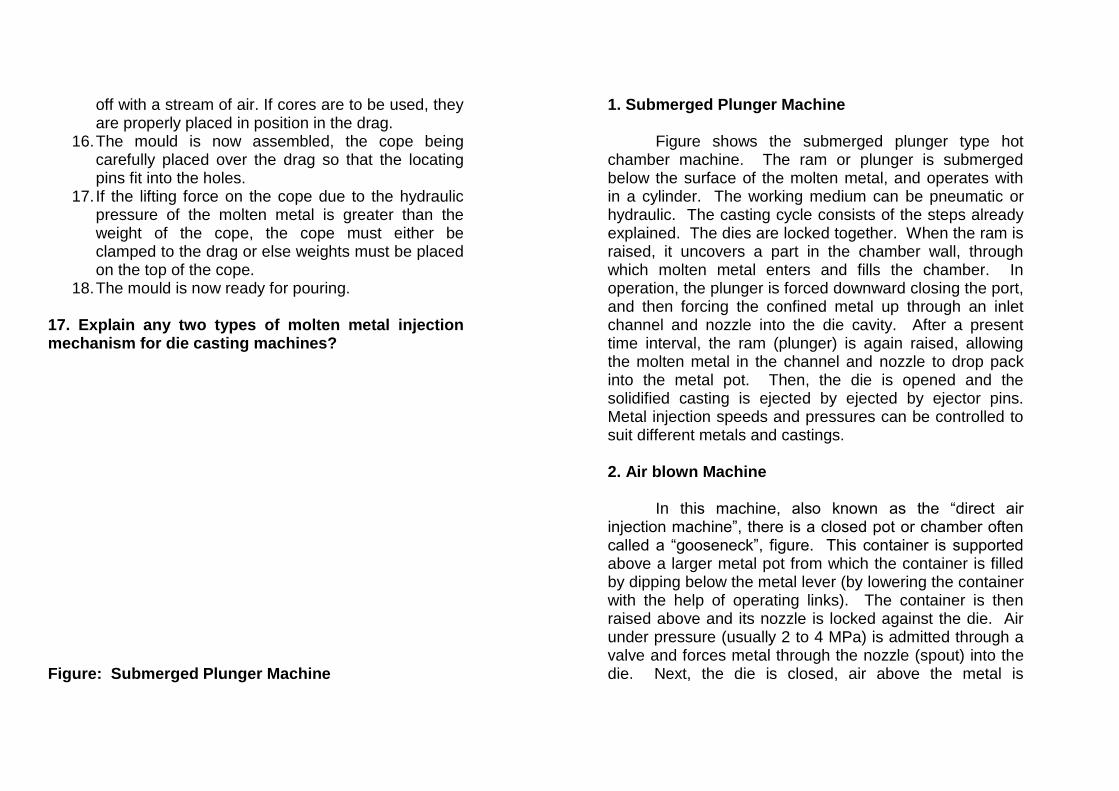
off with a stream of air. If cores are to be used, they are properly placed in position in the drag.
16. The mould is now assembled, the cope being carefully placed over the drag so that the locating pins fit into the holes.
17. If the lifting force on the cope due to the hydraulic pressure of the molten metal is greater than the weight of the cope, the cope must either be clamped to the drag or else weights must be placed on the top of the cope.
18. The mould is now ready for pouring. 17. Explain any two types of molten metal injection mechanism for die casting machines? Figure: Submerged Plunger Machine
1. Submerged Plunger Machine
Figure shows the submerged plunger type hot chamber machine. The ram or plunger is submerged below the surface of the molten metal, and operates with in a cylinder. The working medium can be pneumatic or hydraulic. The casting cycle consists of the steps already explained. The dies are locked together. When the ram is raised, it uncovers a part in the chamber wall, through which molten metal enters and fills the chamber. In operation, the plunger is forced downward closing the port, and then forcing the confined metal up through an inlet channel and nozzle into the die cavity. After a present time interval, the ram (plunger) is again raised, allowing the molten metal in the channel and nozzle to drop pack into the metal pot. Then, the die is opened and the solidified casting is ejected by ejected by ejector pins. Metal injection speeds and pressures can be controlled to suit different metals and castings. 2. Air blown Machine
In this machine, also known as the “direct air injection machine”, there is a closed pot or chamber often called a “gooseneck”, figure. This container is supported above a larger metal pot from which the container is filled by dipping below the metal lever (by lowering the container with the help of operating links). The container is then raised above and its nozzle is locked against the die. Air under pressure (usually 2 to 4 MPa) is admitted through a valve and forces metal through the nozzle (spout) into the die. Next, the die is closed, air above the metal is

released and exhausted, and the gooseneck is lowered to be refilled, breaking away at the end of the sprue where the spout is kept hot by a flame. After the casing formed in the die solidifies, the die is unlocked and opened and the casting is ejected. After, relocking the die, the cycle is repeated.
The metal enters the die in a spray of finely divided particles. Because of this spraying action, air is entrapped in the cavity resulting in porosity in the casting. Metals which have a dissolving effect on iron and steel (material of gooseneck) should not be used. The machine is rather slow and expensive to operate. Due to the above factors, the machine is rather slow and expensive to operate. Due to the above factors, the machine has been gradually replaced by the cold chamber die casing machine.
18. What is core? What are the essential qualities of core? Definition. A core is a body made of refractory material (sand or metal, metal cores being less frequently used), which is set into the prepared mould before closing and pouring it, for forming through holes, recesses, projections, undercuts and internal cavities. Essential qualities of a core. the cores are subject to much more several thermal and mechanical effects than the mould, because, they are surrounded on all sides (except for the ends) by molten metal. Consequently, core sands should meet more stringent requirements. The dry strength and surface strength of a core must be higher than that of a mould. Core sand must have high refractoriness, good permeability and sufficient collapsibility.
The strength of a core will depend on the kind of sand an binding material used. Their bond strength must be greater to allow handling. Also, because they generally are subjected to bending forces produced by the hydrostatic pressure of the liquid trying to lift the core, the bond strength can be increased by using sand with sharper grains which bond together better.
As already discussed, permeability will depend on grain size and distribution of grains in the core sand mix. It will also depend upon the type and content of the binder.

Refractoriness or thermal stability of core can be increased by giving a thin coating of graphite or similar material to the surface of core.
A core should be capable of collapsing shortly after the molten metal has solidified around it. A lack of this ability to decrease in volume may lead to the formation of cracks in the casting as the metal cools. Collapsibility is enhanced by using oil binding materials. 19. Explain the different types of core with neat sketch? The cores can be classified in many ways: a) According to state of Core i) Green sand core ii) Dry sand core
A green sand core is formed by the pattern itself when it is being rammed [figure (a)]. The core is made of the sand as the moulding sand. Such cores are weak and can be used only for light castings.
Figure: Types of Cores.

Dry sand cores are made separately (as explained above) and then positioned in the mould, after the pattern is taken out and before the mould is closed. These are the cores most commonly used. b) According to the position of the Core in the Mould i) Horizontal Core
This core is placed horizontally in the mould and is very common in foundaries. It is usually positioned along the parting line of the mould. ii) Vertical Core
These cores are positioned vertically in the mould, [see figure (b)]. The two ends of the core rest on core seats in cope and drag. The maximum portion of the core is supported in the drag. iii) Balanced core
[Figure (c)] These cores are used when blind holes along a horizontal axis are to be produced. Since the core is supported only ate one end, the core seat should be of sufficient length to prevent its falling into the mould. iv) Hanging Core
[Figure (d)] These cores are used when a cored casting is to be completely moulded in the drag, with the help of a single piece solid pattern. The core is supported
above and hangs into the mould. A hole in the upper part of the core is provided for the metal to reach the mould cavity. v) Drop core
[Figure (e)] This core is used when a hole which is not in line with the parting surface is to be produced at a lower level. 20. Explain the following: 1. facing sand 2. Backing sand 3. System sand 4. Parting sand. 1. Facing sand. This sand is used directly next to the surface of the pattern and comes into contact with the molten mela when the mould is poured. As a result, it is subjected to the severest conditions and must posses, therefore, high strength and refractoriness. This sand also provides a smoother casting surface and should be of fine texture. It is made of silica sand and clay, and some additives without the additions of used sand. The layer of facing sand in a mould usually ranges from 25 to 50mm. 2. Backing Sand. This is the sand which is used to back up the facing sand and to fill the whole volume of the flask. Old, repeatedly used moulding sand is mainly employed for this purpose. 3. System Sand. In mechanized foundries, where machine moulding is employed a so called “system sand” is sued to fill the whole flask. Since the whole mould is made up of this system sand, the strength, the
permeability and refractoriness of the sand must be higher than that of backing sand. Facing sand is always used to make dry sand molds while system sand is frequently used for green sand moulding. 4. Parting Sand. This sand is used to prevent adhering of two halves of mould surfaces in each moulding box when they are separated. Thus, to ensure good parting, the mould surface (at contact of cope and Drag) should be treated with parting sand or some other parting material. It is also sprinkled or applied on the pattern surface (before the moulding sand is put over it) to avoid its sticking and permit its easy withdrawal from the mould. The parting sand is fine dry sand. There are other parting materials also sued in foundary . 21. Explain: core, core prints, pouring basin, sprue, sprue base, runner, gates, and risers. Core. It is made of core sand (or of some other suitable material and even of metal) and is used to make holes in the casting . (b) Core Prints. Core prints are the projections on a pattern and are used to make recesses (core seats) in the mould to locate the core. (C) Pouring Basin. It is a reservoir at the top of the sprue ( in cope) that receives the stream of molten metal poured from the ladle.
(d) Sprue. A sprue or down gate is a vertical channel that connects the pouring basin with runners and gates. It is made somewhat tapered downward for case of moulding and more importantly to have a decreasing cross-sectional area corresponding to the increase in velocity of the molten metal as it flows down the sprue hole. This prevents turbulents flow and hence the drawing in or air along with the liquid into the mould cavity. (e) Sprue base or well. It is a reservoir at the bottom end of the sprue. It prevents excessive sand erosion when the molten metal strikes the runner at the sprue base. Also, there is considerable loss of velocity in the well. (f) Runner. The runner is generally a horizontal channel whose functions are to trap slag and connect the sprue base with the gates (ingates), thus allowing the molten metal to enter the mould cavity. (g) Gates. The gates (ingates) are the channels through which the incoming metal directly enter the mould cavity. (h) Risters. The risers or feed heads are a part of the feeding system. These are reservoirs of molten metal that feed the metal in the casting proper as it solidifies, to prevent shrinkage cavities in the casting. 22. Explain the various types of materials used in foundries for the manufacture of casting moulds and cores.
Various types of materials are used in foundaries for the manufacture of casting moulds and cores. These

materials are divided into two groups: Basic and Auxiliary. Basic moulding materials include: silica sands, which from the base and the various binders. The auxiliary group includes various additives which impact desired properties to the moulding and core sands. The essential constituents of a moulding sand are: Silica sand, Binder, Additives and water. Silica sand as the widely used moulding material has the following advantages:
1. It is cheap, plentiful and easily available 2. It is characterized by a high softening
temperature and thermal stability, that is, highly refractory.
3. Easily moulded, reusable and capable of giving good details.
Silica sand forms the bulk of the moulding sand.
Binder (most common is clay) may be present in natural sand or added to silica sand separately. In combination with water, it is the bonding agent in green sand. Although moist sand particles do adhere to one another slightly, but coating with moist clay, the strength (tensile and shear) of the sand mix is increased about three-fold. Clay imparts cohesiveness and plasticity to the moulding sand in the most state and increases its strength after drying. When the moulding sand has the proper amount of water added to it to give a high strength with sufficient plasticity, the sand is said to be “at temper” or “tempered”.
Additives impart to the moulding sand special properties (strength, thermal stability, permeability, refractoriness, thermal expansion etc.) Sand. According to the amount of clayey matter they contain, the moulding sands are classified as:
1. Silica Sand: Upto 2% clay. 2. Lean or weak sand: 2 to 10% clay 3. Moderately strong sand: 10 to 20%clay 4. Strong sand: Upto 30% clay 5. Extra Strong sand (Loam sand): upto 50% clay.
There are three types of sand used for making moulds: natural, synthetic and chemically coated.
1. Natural Sand. A natural sand is the one which is available from natural deposits. Only additives and water need be added to it to make it satisfactory for moulding. The clay content of most natural sands is slightly higher than desired so that new sand can be continuously added to the used sand to replenish that which is lost.
2. Synthetic Sand. A synthetic sand is prepared by mixing a relatively clay free sand having a specified type of sand grain, with a specified type of clay binder as well as water and other additives. All are mixed in the foundary. This sand has the advantage that sand grains of specified composition and properties can be prepared on the basis of the metal being cast.

3. Chemically coated sand. Clean silica grains are sometimes coated with a non – thermosetting hydrocarbon resin, which acts as a binder. An additional binder in the form of clay can also be used. The advantage of this sand is that the carbon in the resin which is an excellent refractory surrounds the sand grains and does not allow the molten metal to reach the sand grains. This produces casting with clean surfaces as the sand does not get fused in them. The moisture content in this sand is kept to above 3%.
Moulding sands exhibit maximum strength at a moisture content of 4% for lean sands and of 6 to 7% for loam sands. A typical green moulding sand for gray iron moulding are given below:
Silica sand = 68 to 86% Clay = 10to 20% Water = 3 to 6% Additives = 1to 6%
Binders. Binders used in a foundary are: Inorganic and organic binders. Organic binders are mainly used for core making and will be discussed later.
Clay binders are the most common inorganic binders. Clays are formed by the weathering and decomposition of rocks. The common types of clay used in moulding sand are: Fireclay, kaolinite, little and Bentonite. Kaolinite and
Bentonite clays are most popular, because, they have high thermochemical stability.
1. Fire-clay. Fire clay is a refractory clay usually found in the coal measures.
2. Kaolinite. Its general composition is AI2O3.2SiO2.2H2O. It is one of the decomposition products of the slow weathering of the granite and basalt ( a kind of black rock). It is the main constituent of China fire clay. Its melting point is 1750 to 1787oC.
3. little. This clay has the approximate composition: K2O. AI2O3. SiO2. H2O. It is formed from the weathering of mica rocks. Its particle size is about the same as the kaolinite clay and has similar moulding properties.
4. Bentonite. Its general composition is MgO. AI2O3.SiO2.H2O. It is formed from the weathering of volcanic or igneous rocks. It is creamy white powder. Its melting point is 1250-1300oC.
The basic constituent which gives refractoriness to a
clay is alumina, AI2O3. Of all clays, bentonite is the most commonly used clay. It needs smaller amount of water to obtain a given degree of plasticity. This will result in less steam generation when the molten metal is poured into the mould, permitting a lower permeability in the moulding sand. Other binders can be: Portland cement and Sodium silicate.

The percentage of binder in the moulding sand is of great importance. The bond must be strong enough to with stand the pressure of sand erosion by the melt, yet it must be sufficiently weakened by the heat of metal to allow shrinkage of the casting and finally removal of the sand without damage to the solid casting. However, bond must not destroy the permeability of the sand so that gases present in the melt or produced by the eat of the melt in the binder itself can escape. 24. Explain color scheme for patterns. Colour Scheme for Patterns. Frequently, a print of the finished part is not furnished with a pattern. As a result, the foundary man is not able to take the necessary precautions to produce the best results. Many mistakes may be eliminate by indicating the functions of the various parts of the pattern with proper colours.
(a) A loose piece may get lost and unless the pattern is marked to indicate the seat of the loose piece, it is quite possible that the casting will be made from the incomplete pattern.
(b) With properly marked core prints, the moulder is constantly reminded that cores must be set in the mould before it is closed.
(c) Patterns with stop offs should be marked to remind the moulder to fill the mould cavity made by the stop off.
(d) If a moulder knows what surfaces are to be machined, he will, if possible mould the
pattern in a position to produce a surface more nearly free of impurities.
The foundries may use their own cololur schemes. A common colour scheme is given below: 1. Surface : Black 2. Machined surface : Red 3. Core prints and seats : Yellow 4. Loose pieces : Yellow/Red diagonal strips 5. Stop-off : Yellow /Black diagonal stripes

UNIT – II
PART – A 1. Define welding. Welding is defined as an localised coalescene of metals, where in coalescence is obtained by heating to suitable temperature, with or without the application of pressure and with or without the use of filler metal. 2. Classify the different welding processes.
3. Define gas welding. Gas welding is a group of welding processes where in coalescence is produced by heating with a flame or flames with or without the application of pressure and with or without the use of filler material. 4. Differentiate between Autogeneous, Homogeneous an Hetro-geneous welding process. Auto Geneous welding processes : No filler metal is added to the joint interface. Eg. Electric resistance welding. Homo Geneous welding processes : Filler metal is added and is of the same type as the parent metal. Eg. welding of plan low – C steel with a low – c welding rod Heterogeneous welding processes : Filler metal is used but is of a different type from the parent metal. Eg. Brazing and soldering. 5. Sketch the various types of weld used in making a joint.
Bead Weld
Welding
Fusion Welding Brazing & Soldering Solid State Welding
Chemical Electrical Electrical Chemical
Resistance Diffusion Exposion
Mechanical
Cold Friction
Ultrasonic
Oxyfuel gas Thermit
Arc Resistance
Electrical Beam Laser Beam

spot weld Groove weld Fillet weld 6. Sketch the various welded Joints. a.Butt Joint b.Lap Joint C.TJoint d. Corner Joint
7. Sketch the three types of flame used in oxy – acetylene welding processes.

8. Why the cleaning of a Joint is necessary before welding. The weld area must be free of oil, dirt, grease paint (or) moisture etc. These will interfere with the proper fusion on the metal and result in a weak Joint. 9. What is the function of flux in welding (2006) The flux is used in welding to prevent oxidation and to removes impurities. It is also added in welding to control the detrimental effects. 10. What is Lamellar Tearing? (2006). In the welding of such components, lamellar tears may develop, because of shrinkage of the restrained components in the structure during cooling. Such tears can be avoided by providing for shrinkage of the members to make the weld bead penetrate the weaker component more deeply. 11. What is Thermit welding. Thermit welding is a group of welding processes where in coalescence is produced by heating with super heated liquid metal and slag resulting from a chemical reaction between a metal oxide and aluminium with or without the application of pressure. Thermit is a mixture of powered aluminium (1 part) and iron oxide in the form of roll scale (3 parts).
12. Define electric arc welding. An arc is an electric discharge between two electrodes which takes place through an electrically conductive hot ionized gas known as plasma. An electric arc used for welding is called electric are welding. 13. Sketch and compare the two welding techniques used in OAW processes. (Forward welding) Leftward Technique: In left ward welding technique, the torch flame progresses from right to left. The method allows preheating of the plate edges immediately ahead of the molten pool and this is the method more commonly used.

Rightward Technique: (Back ward Technique) In the right ward Technique, welding commences at the left hand side of the plates and proceed towards the right. In this technique weld puddle is kept for a longer time and a narrow and deeper weld results.
14. Sketch the two polarities of DC supply for welding process. Direct Current straight polarity: Direct current reverse polarity:

15. Write on the different types of electrodes used in arc welding. Electrodes used for arc welding are of two types:
- Non consumable electrodes - Consumable electrodes.
Consumable electrodes are of three kinds:
- Bare electrodes. - Fluxed electrodes - Coated electrodes.
16. What is the purpose of coating on electrodes?
- Provides a Protective gaseous atmosphere to prevent 02 H2 and N2 pick up by the molten metal.
- Improves arc stability have providing certain chemicals which have this ability, by ionizing the path of arc.
- Provides a slag over hot metal. - Reduces spatter of weld metal – when coating
burns off slower than one. 17. Name the shielding gases used in inert gas arc welding.
- Helium, Argon, Helium, - Argon, Co2.
18. Define Resistance welding process. [June 2007]. Resistance welding is a group of welding processes where in coalescence is produced by the heat obtained from resistance of the work to electric current in a circuit of which the work is a part, and by the application of pressure and without the use of filler metal. 19. Name six types of Resistance welding processes.
1. Resistance spot welding. 2. Resistance seam welding. 3. Projection welding. 4. Flash welding 5. Upset welding 6. Percussion welding.
20. Define weldability. Weldability relates to ease with which a metal can be welded and to the properties of the joint compared with those of parent metal. Ease of welding depends upon the melting temperature, thermal conductivity, thermal expansion and surface condition of work. 21. What metals may be spot welded? Can dissimilar metals be spot welded? Spot welding is primarily restricted to thin metals, namely steels, stainless steel, aluminium, nickel, nickel alloys. Some dissimilar metals can be spot welded but with difficulty.

22. Write the various spot welding machines. 1. Standard Machines.
i) Rocker arm type ii) Press type spot welders.
2. Rocker arm type Machine
i) Foot type ii) Air operated M/c iii) Press type m/c
3. Special Multiple electrode Machines, 4. Portable welders.
23. Write the special features of Resistance Projection welding.
- Pieces of Unequal thickness can be welded - Suitable for welding copper, Aluminium, Brass.
24. Write the applications of Flash butt welding.
- Used for joining thin walled tubies, rails, chain links, and tools.
- Dissimilar metals such as refractory metals, including tungsten, tantalum and molybdenum can be welded.
- Joining of rims of wheels for automobiles.
25. Define Friction welding.
- Friction welding is defined as a solid state welding process where in coalescence is produced by heat obtained from mechanically induced sliding motion between rubbing surfaces. Parts are held together under pressure.
26. Write the special features of Friction welding.
- Low initial capital cost - Low – cost power requirements. - Annealing of weld zone is not necessary.
27. Define submerged are welding. In this coalescence is produced by heating with an arc between a bare wire electrode and the work. Weld zone is shielded by a blanket of fusible granular flux material supplied directly on the weld seam ahead of the electrode to shield the arc. 28. Define Diffusion welding. A solid state welding process, where in coalescence is produced at the faying surfaces by the application of pressure and elevated temperatures. Process does not involve macroscopic deformation of parts.

29. Define Brazing. Process to join two metal pieces heated to suitable temperatures by using a filler metal having liquid us above 427.c and below the solid us of base filler metal is distributed between the closely fitted surfaces of the Joint by capillary attraction. 30. Write the various fluxes used in brazing processes.
- Composition of borates, Fluorides, chlorides, borax and boric acid
31. Write the different brazing methods.
- Torch brazing, Furnace brazing, Induction brazing, Dip brazing and Resistance brazing.
32. Define soldering. In soldering, two parts are joined by the use of molten filler metal whose melting point is below the solidus and in all cases below 427oc 33. What are the types of fluxes used in soldering?
1. Corrosive type
- Zinc chloride, mixtures of zinc chloride and Ammonium chloride.
2. Non corrosive type.
- Rosin and Rosin plus alcohol.
34. What are the various steps in brazing?
- Surfaces to be joined are cleaned and fitted closely together.
- Flux is applied to all surfaces where the filler metal is to flow
- Joint is heated to the proper brazing temperature. Solid filler metal may be pre placed on the metal pieces and thus melted as the metal pieces are heated.
- Small amount of filler metal is needed to fill the joint completely.
35. What are the requirements of good flux?
- Low viscosity so that it is replaced by molten filler metal.
- May react with surfaces to facilitate wetting. - Shields the joints while the filler is still liquid.
36. What are the various welding defects?
- Porosity, under cut, cracks, Inclusions, Lack of fusion, Burning, Internal cracks.
37. Define soft solder. Most widely used solders are alloy of tin and lead. Small Quantities of some other metals may also be added. These filler metals used in soldering are called soft solder.

PART - B 1. Explain the different types of Flames that occur in gas welding with neat sketch and their applications. 1. Neutral Flame: A neutral flame is obtained when equal amounts of O2 and C2 H2 are mixed and burnt in a torch. The flame is recognized by two sharply defined zones, the inner white cone flame and the outer blue flame envelope, (Figure (a)). The reaction at the inner cone for the neutral flame where equal volumes of cylinder oxygen and acetylene are used is, C2H2 + O2 2 CO + H2
This provides the most concentrated heat with the highest temperature for welding at a distance of 3 to 5 mm from the end of the inner cone. It is also apparent that the environment within the outer envelope consists of carbon monoxide and hydrogen and is relatively inert to materials that oxidize readily. The reactions at the outer envelope are: 2 CO + O2 2 CO2
H2 +1
2 O2 H2O (vapour)
For these reactions, the oxygen is supplied from the
surrounding air. During actual welding, the outer envelope spreads over the surface of the work material and serves as a protective shield from the ordinary atmosphere. Also, since the heat developed is not as concentrated, this outer envelope of flame contributes only to preheat the work material for welding. 2. Carburising Flame: A carburizing or reducing flame is obtained when an excess of acetylene is supplied than which is theoretically required (O2 : C2H2 = 0.85 to 0.95). A reducing flame is recognized by three distinct sections: the inner cone (which is not sharply defined) and an outer envelope as for the neutral flame. The third zone surrounds the inner cone and extends into the outer enveloping zone. It is whitish in colour and is called “excess acetylene feather”. Its length is an indication of the amount of excess acetylene. (Figure (b)).

To obtain a neutral flame, first the reducing flame is obtained. Then the supply of oxygen is gradually increased until the intermediate feather disappears. The resulting flame will be a neutral flame. 3. Oxidising Flame: This flame has an excess of oxygen over that required for a neutral flame, the flame is first set to the neutral condition. Then the acetylene valve is turned down gradually to reduce the amount of acetylene, giving an excess of oxygen. The flame resembles the neutral flame except that it acquires a light blue tint and the inner cone is slightly shorter and more pointed than in a neutral flame (Figure (c)). An oxidising flame burns with a harsh sound and the outer envelope is short and narrow. Applications of three-types of flames:
(a) Neutral Flame: In most welding situations, it is theoretically desirable to use a neutral flame, but in practice it is very difficult to discern whether the flame is neutral or Oxidising, either a slightly reducing oxidising flame is used.
If possible, most welding should be done with a neutral flame, since such a flame has a minimum chemical effect upon most heated metals. The flame is widely used for the welding of steel, stainless steel, cast iron, Copper and Aluminium.
(b) Reducing Flame: The acetylene being excess in this flame, the available carbon is not completely
consumed. With iron and steel, it will form iron carbide (hard and brittle). Therefore, metals that tend to absorb carbon should not be welded with a reducing flame. This flame is used steels, low c-steels and for welding those metals (for example, non-ferrous) that do not tend to absorb carbon. Such flames are also used for welding Monel metal and Nickel and in hard surfacing with high speed steel and cemented carbides.
(c) Oxidising Flame: This flame has limited use
because the excess oxygen tends to combine with many metals to form hard, brittle, low strength oxides. Also, excess of oxygen causes the weld bead and the surrounding area to have a skummy or dirty appearance. So, this flame is not used for welding steel. It is mainly used when welding materials which are not oxidized readily and which have a high solubility of hydrogen in the molten state and low solubility in the solid state, for example, brasses, bronzes and gold. For these metals the oxidising atmosphere creates a base metal oxide that protects the base metal. For example, in welding brass, Zinc has tendency to separate and fume away. The formation of a covering copper oxide prevents Zinc from dissipating.

2. Explain gas metal arc welding with neat sketch their advantages and disadvantages.
(i) Gas Metal Arc Welding, (GMAW). The method is also known by the acronym, MIG (metal inert gas). The method differs from TIG in that a consumable electrode in wire form is fed into the arc, (Figure). The same shielding gases are used. The wire is automatically fed from the reel by a variable speed motor at a preset rate that is determined by the arc voltage. The wire feed increases with an increase in arc voltage caused by an increase in arc length. This process has a greater efficiency than TIG and is more rapid. In semiconductor-automatic welding, the welder guides the gun and adjusts process parameters; in automatic welding all functions are taken care of by the welding machine or robot.
Shielding Gases: The shielding gases commonly used are : Helium, Argon and CO2 or their mixtures. The gases must be pure, clean and free of moisture.
Figure MIG. Helium: It yields better penetration than argon. It has high specific heat co-efficient. So, the temperature of the weld is reduced, minimizing distortion as well as facilitating penetration. But it is costlier than argon. Also it is much lighter than argon, so more gas flow is required for a given performance as compared to argon.
Argon: It has better electrical properties than helium, for example, ionization voltage is lower which helps in producing more stable arc conditions when using a.c. It is cheaper than helium. It gives a superior oxide cleaning action with a.c. on Aluminium, Magnesium, Copper and Beryllium. It gives a softer arc and less penetration, so it is generally more suitable for thinner metals. Carbon Dioxide: It is considerably cheaper than helium or argon. But it produces more spatter and poorer bead shape when used alone. So it is usually used in conjunction with argon (80% argon, 20% carbon dioxide). Advantages of Inert Gas Shielded Arc processes: In both job-shop and mass production work, inert gas shielded arc processes are being increasingly employed in place of SMAW, due to the following reasons:
1. Much greater penetration and higher welding speeds are possible, because of the higher currents which can be used.
2. There is no slag to clean off after welding, because no flux is used.’
3. Produce very high quality and clean welds on almost any material in any welding position.
4. The weld zone is visible. 5. No possibility of cracks. 6. There is no weld patter. 7. It is fast and economical, because there are no
frequent changes of electrodes. 8. It can be readily automated.
9. The process does not require high degree of operator skill.
Drawbacks:
1. The surfaces to be welded must be clean and fee of oil, grease, paint or rust, because the inert gas does not provide any cleaning or fluxing action.
2. On site welding can be difficult because drafts blow the shielding gas away from the weld zone.
3. Difficult to weld in small corners. 4. Welding equipment costly, more complex and less
portable. 3. Explain the Principle of submerged arc welding, with their limitations. Submerged Arc Welding, (SAW): In this, coalescence is produced by heating with an arc between a bare wire electrode and the work. The weld zone is shielded by a blanket of fusible granular flux material supplied directly on the weld seam ahead of the electrode to shield the arc. Pressure is not used and molten filler metal is obtained for the electrode. The flux also acts as a deoxidizer and scavenger and may contain powder metal alloying elements.
The method can be used in fully automatic equipment where the feeds of both the electrode and granular flux are controlled, Figure. The method is also adaptable for semiautomatic equipment where the feed of the electrode and granular flux are controlled manually.

Figure: Submerged Arc Welding.
This method is characterized by good appearing welds, high welding speeds and high welding currents upto several thousand amperes. Because of the large diameter electrodes which can be used, rather large welds can be made in one single pass in plates over 25 mm thick. Deep penetration is also obtained.
Since the granular flux must cover the joint to be welded, this method is restricted to making straight welds in the flat position. Thus it is suitable for steel line pipes, boiler pressure vessels, railroad tank cars, structural shapes and cylinders etc. and also for circular welds if the work piece is rotated under the welding head. Double submerged arc welding (with one weld from the inside, the other from the outside) is used in making spiral- welded pipelines. It can also be used with welding robots, with the workpiece manipulated into appropriate positions.
Submerged arc welding can be used to weld low C-steels, high strength low alloy steels, chromium steels, and austenitic chromium-nickel steels. With special methods, it is also possible to weld high-alloy air hardening steels.

Advantages:
1. Joints can be prepared with a shallow V-groove, resulting in lesser electrode consumption.
2. Wire electrodes are inexpensive. 3. Weld spatters are eliminated. 4. Nearly 100% deposition efficiency is achieved.
Limitations:
1. It can not be used for plates less than 5 mm thick. 2. It can not cut C.I. because of high heat input. 3. Slag has to be removed continuously after it has
melted in order to avoid entrapment between passes.
4. Explain the Electro slag welding processes. Electro-Slag Welding, (ESW): In this process, electrode wire (consumable) is fed into a molten slag pool. An arc is drawn initially, but is then snuffed out by the slag, and the heat of fusion is provided by resistance heating in the slag.
The components to be welded are set in a vertical position with a distance of from 15 to 30 mm between the butted edges depending upon their thickness. The welding wire and the flux are fed automatically into the clearance, (Figure). Several electrode wires can be fed simultaneously if the parts to be welded are quite thick. Water cooled copper shoes or slides (dams) travel upwards along the joint. They close off the space between the parts to be welded to prevent the slag and molten
metal from spilling out of the pool. They also cool the pool of metal and form the weld. Figure: Electro-Slag Welding.
An arc is established between the steel backing plate and the electrode wire only at the very beginning of operation before a pool of molten metal and flux of sufficient volume has accumulated. Further melting of the electrode and base metal is due to the current flow between the electrode, pool and slag. The molten base metal and the filler metal (from the electrode) sink to the bottom of the slag pool, cool and form a weld in the joint between the components.
The chief advantage of ESW is that very thick components (up to 400 mm thick) can be welded together in a single pass without beveling the edges. This is due to

the fact that several electrode wires are brought simultaneously into the welding zone. A very clean weld is obtained, without any slag inclusions.
The method is highly productive and pre-dominantly applied in heavy engineering in the manufacture of bed and frames for heavy machinery, drums, boilers etc. 5. Explain the different types of electrodes coatings and their functions. Functions of Coatings:
1. Improves arc stability by providing certain chemicals which have this ability, by ionizing the path of arc.
2. Provides a protective gaseous atmosphere to prevent O2, H2 and N2 pick-up by the molten metal.
3. Provides a protective slag over hot metal. 4. Provides flux, which helps to remove oxides and
other impurities from the molten weld metal. 5. Reduces spatter of weld metal- when coating burns
off slower than core. 6. Acts as deoxidizer. 7. Adds alloying elements. 8. Increases deposition efficiency. 9. Slows down the cooling rate of weld (due to
protective layer of slag) to prevent hardening. 10. Coatings are normally insulators of electricity of
electricity and so permit the use of electrodes in narrow grooves etc.
Types of Electrode Coatings: There are four main types of coatings which are most commonly used in practice:
1. Cellulosic coating. 2. Rutile coating. 3. Iron oxide coating. 4. Basic or low H2 coating.
The first two coatings are almost identical but with one
difference. The percentage of Titanium dioxide, TiO2 (rutile) is somewhat more in rutile coating than in Cellulosic coating. When the cellulose burns, it results in the evolution of a mixture of gases. H2 and CO. These gases provide a protective shield to the molten base metal.
With the same thickness of the work, a Cellulosic coating results in deeper penetration as compared to rutile coating. Since the rate of evolution of H2 gas is high, there is a danger of hydrogen embrittlement of the base metal, with these two coatings.
In iron oxide coating, the evolution of H2 gas is less as compared to the first two coatings. Therefore, protection to the molten base metal is mainly provided by slag.
In basic coating, the major constituents are calcium carbonate and fluorspar (CaF2). When this coating burns, it results in the evolution of a mixture of CO and CO2 gases. This mixture provides protection to the molten base metal. This coating has certain advantages over the other

coatings: There is no danger of hydrogen embrittlement of the welded joint. The mixture (CO + CO2) is less reducing than H2 gas. So, a shorter arc length is maintained for complete shielding of molten base metal.
The thickness of the coating will depend upon the size of the job. Thicker coating results in narrower and deeper penetration.
It should be noted that with A.C. supply, the arc goes off after every half cycle when cycle crosses the zero current line. No such thing happens with D.C. supply. So, with A.C. supply, the arc must reignite after every half cycle. The reignition voltage is higher than the normal arc voltage. However, the process of reignition is facilitated by the presence of ions of low ionization potential, in the gap. Now, potassium has low ionization potential (4.3V) as compared to sodium (5.1V). Hence, with A.C. supply, the electrode coating has potassium silicate as the binder, and with D.C. supply, it is sodium silicate. 6. Explain the principle involved in plasma arc welding with neat sketch. Plasma Arc Welding, (PAW): The term ‘plasma’ refers to a gas which is sufficiently ionized (by raising it to a high temperature) to conduct current freely. A conventional welding arc is an example of a plasma. A plasma jet is created when the arc is passed through a constrictive nozzle. As a result of this constriction, the plasma jet will take on a narrow, columnar shape with unique properties that make it ideal for welding. Plasma jet welding is an
electric-arc welding process which employs a high temperature constricted arc or plasma jet to obtain the melting and coalescence of metal. Shielding is obtained from the hot, ionized gas issuing from the nozzle, coalescence of metal. shielding is obtained from the hot, ionized gas issuing from the nozzle, which may be supplemented by an auxiliary source of shielding gas. Pressure is not applied and filler may or may not be supplied.
The basic circuitry of a plasma arc welding torch is shown is Figure. The plasma torch is constructed with an electrode (tungsten) centrally within a metal cup that guides an inert Figure: Plasma arc welding.

streaming gas past ht electrode. The discharge end of the cup is smaller in diameter than the upper diameter so that a discharge nozzle is created. In addition, the inner wall of the nozzle is lined with a ceramic materials. The torch has passages for supplying gas and water (to cool it). There are two arrangements of the plasma arc welding:
a) Transferred plasma arc. b) Non-transferred plasma arc.
In the transferred plasma arc, the arc is produced
between the electrode (-ve) and the work (+ve). In the non-transferred arc, the arc is produced between the electrode (-ve) and the nozzle (+ve). The work is heated indirectly by radiation. The heat is carried to the workpiece by the plasma gas.
The gases used should be inert (non-oxidising ) and with a higher thermal conductivity, so that they can transfer more heat, making it possible to weld bulky section more easily. Usually, the shielding gas is the same as the orifice (nozzle) gas. Argon, Helium and hydrogen or their mixtures are the gases most frequently used.
Plasma arc provides an intense source of heat (Arc temperature of about 14000 K) and ensures greater arc stability. PAW is used for quality welding and can easily weld 127 mm thick aluminium sections or stainless steel sections upto 100 mm thick. The welded joints have no
porosity and display a strong resistance to high stresses and impact loading. 7. What is Resistance welding? Explain Resistance spot welding process in detail with heat sketch. Resistance welding :
Resistance Welding is “a group of welding processes where in coalescence is produced by the heat obtained from resistance of the work to electric current in a circuit of which the work is a part, and by the application of pressure and without the use of a filler metal”.
The amount of heat generated at the contacting area or the elements to be welded, is determined from Joule’s law, Q = I2 Rt, joules where I = current in amperes R= resistance of the circuit at the contacting
area of the elements in ohms. t= time during which the current flows, in
seconds. The voltage can be low, typically 0.5 to 10V, but currents are very high (thousands of amperes). Materials of high heat conductivity and specific heat (Al and Cu) call for very high currents to prevent dissipation of heat.

1. Resistance Spot Welding (RSW): In resistance spot welding, the overlapping metal parts are held between two bar type metal electrodes which apply pressure, while an electric current is passed through them, Figure. When the current is switched on and applied for a Figure: Resistance Spot Welding. predetermined number of cycles (in the automotive industry 20-30 cycles), the lapped pieces of metal are heated in a restricted area. The generated heat melts the surface layer of the metal in the central, more highly heated, area of contact with the electrodes, and the adjacent layers of metal are softened to a plastic state. Then the current is switched off and the electrodes are pressed and the pressure is released only after the weld spot (nugget) has solidified. The spot weld (nugget) is
approximately the same size as the electrode tip, usually between 3 or 6 mm in diameter. Electrode tip diameter = Thickness of plate to be welded. Distance between the nearest edge of the plate and centre of weld = 1.5 x electrode tip diameter. The sheet surface shows a slight depression and decolouration. The welding cycle to produce one spot can be written as:
(i) Position the workpieces and squeeze between the electrodes.
(ii) Apply a low voltage current to the electrodes. (iii) Hold until the proper temperature is attained. (iv) Release current, continue pressure. (v) Release pressure and remove work.
The electrode pressure can be in the range of upto 2 kN
The electrodes used must possess high electrical and thermal conductivity and retain the required strength
at temperatures upto 400C. Electrodes are made of cold-rolled electrolytic copper with some Cd, Cr, or Be additions, or copper – tungsten or molybdenum alloys. Electrodes are usually of hollow construction and are cooled with water during operation to prevent their overheating.
Because of the widespread application of sheet metal parts, resistance spot welding finds extensive application in the aircraft and automobile industries for manufacturing air frames and bodies (there are some 8000 to 10,000 spot welds per car), attaching handles of

cookware, as well as in railway car building and the instrument industry and for making reinforcement in concrete construction etc.
Spot welding is primarily restricted to thin metals (for example 0.025 to 3.2 mm thick for steel and magnesium and 4 mm thick for aluminium), namely steels, stainless steels, aluminium, magnesium, nickel, nickel alloys, bronze and brass. Some dissimilar metals can be spot welded, but with difficulty. However, the method is quite difficult to use for highly conducting materials like Al and Mg.
(a) The diameter of spot welds,
d = 1.2 t + 4 mm, for t < 3 mm = 1.5 t + 5 mm, for t > 3 mm
where t = Thickness of parts being welded.
(b) Spacing of spot welds = 3d. 8. Explain Resistance Seam Welding Process in detail with neat sketch. Resistance Seam Welding, (RSEW): To obtain a series of spot welds along a line by the RSW method, an interrupted work movement will be necessary. The same result can be achieved much more conveniently and rapidly in the resistance seam welding where the electrodes are in the form of rotating disc electrodes, with
the working being welded moving continuously by the electrodes, (figure). Figure: Resistance Seam Welding.
Seam welding may be either intermittent (stitch seam or spaced spots) or continuous seam (over lapping seam). In the former case, a current interrupter is employed. When the a.c. is left on, a spot weld is made every time the current reaches its peak, and the welds are spaced close enough to give a gas and liquid-tight joint.
The rollers are made of the same materials as the electrodes for sport welding. Rollers may vary in diameter from 40 to 350 mm. Welding currents range from 2000 to 5000 A. while the force applied to the rollers may be as high as 5 to 6 kN. Welding speeds range is commonly from 0.5 to 3.5 m/min. In most cases of seam welding, a

stream of water is directed over the disc keep everything cool except the joint interface.
Seam welding is used in the manufacture of tanks, tubes and other articles of steel and non ferrous metals which must have airtight joints.
Seam welding is primarily used for quantity production but is restricted to joining metal gauges that are thinner than those which can be joined bu spot welding. The normal range of thickness compatible with seam welding is 0.25 to 3.2 mm. 9. Explain the Electric Resistance Butt Welding process in detail. Electric Resistance Butt Welding: There are two types of electric resistance butt welding processes: the ‘upset’ and the ‘flash’.
(i) Upset Welding, (UW): In this process, the ends of the two parts to be joined together are clamped in position in the electrodes. The movable head is moved towards the fixed head until the abutting surfaces of the work pieces are in light contact. Then the proper current is made to flow across the interface for a preset time, while the light pressure between the two parts is maintained. When the interface has been heated to the welding temperature (plastic state), the current is switch off and the welding pressure is increased to form an “upset”, (Figure). This
results in the lateral flow of the surface oxide layers, bringing clean metal surfaces in contact. Metal is not melted when upset butt welded and there is no spatter.
Figure: Upset Butt Welding
The welding voltage may vary from 5 to 15V while the current densities range from 300 to 800 A/cm2. Because the contact resistance is inversely proportional to the pressure, therefore, the pressure is less at the start and is then increased to whatever is necessary to effect the weld. Final pressures range from 17 to 55 MPa. Upset butt welding is extensively used in the fabrication of tubular sections, pipe and heavy steel rings. It is also used for joining small ferrous and non-ferrous strips. Areas upto 0.05 m2 have been successfully welded, but generally the process is limited to smaller areas (upto 1000 mm2) because of current limitations.

(ii) Flash Butt Welding, (FW): In this process, the parts to be welded approach towards each other and come into contact with the current switched on. The procedure of butt welding is follows: After the parts are properly positioned and correct current, head speed and time are selected, a cycle start button is actuated. This makes the movable head to approach the fixed head. As the abutting surfaces come very near to each other, extremely rapid heating takes place when surface asperities first make contact. Molten metal is violently expelled and burns in air with considerable force and “Sparking” or “arcing”, thus giving the process its name “flash butt”. As this process continues for a few seconds, a very thin layer at the interface is melted. The current is then shut off and the two parts are rapidly pressed together causing a small parts are rapidly pressed together causing a small upset, (Figure). This squeezes out liquid metal and oxides formed on the joint surfaces and the solid clean metal faces of the abutted parts are welded together.,
This process is used for joining thin- walled tubes, rails,
chain links, tools (low carbon steel shank to H.S.S. tool bit), press manufactured parts. Also, dissimilar metals can readily be welded (such as steel, - copper, -brass; aluminium-copper etc.), including refractory metals such as tungsten, molybdenum and tantalum. The process is extensively used for joining the ends of wire and sheet coils to allow the continuous operation of processing lines.
The other product applications include: joining of rims of wheels for automobiles and cycles, tubular parts such as automobile brake cross-shafts, and parts of metal bodies for motor cars, for welding tube coils for refrigeration plant and for welding new end piece on to the locomotive boiler tubes in replacement of the worn ends, welding of H.S.S. ends on to C- steel shanks during the manufacture of twist drills and other small tools.
The current densities range from 300 – 800 A / cm2 and the welding voltage is from 5 to 15 V. The welding pressure may range from 350 to 1400 MPa.

In accordance with their capacity and purpose, butt welding machines may be either hand-operated or automatic. The latter type clamps the parts to be welded and apply pressure for upsetting by mechanical, hydraulic or pneumatic means, and the process is controlled automatically. In the mechanical system, the movable head is moved towards the fixed head by means of a cam drive. The upset metal is usually removed by subsequent rolling or grindling. 10. What is Friction welding? Explain the Principle involved in it. What are the advantages and disadvantages of the process? Friction Welding (FRW): Friction welding is defined as “A solid state welding process wherein coalescence is produced by heat obtained from mechanically induced sliding motion between rubbing surfaces. The parts are held together under pressure”. One part is rotated at relatively high speeds and under pressure against the second part which is held stationary. The frictional work at the contacting surfaces is transformed into heat. The contacting surfaces are thus heated to a high temperature below the melding temperature. At this point, the relative motion between the two is stopped. The weld is then completed (by upsetting) due to the pressure which still continues or additional pressure may be necessary, (Figure), to produce a solid state weld. Axial pressure,
when rotating, may be upto 70 MPa and at the end it may reach 140 MPa. Relative motion is stopped by:
(i) a braking system to the machine spindle. (ii) an arrangement which releases the stationary
part to permit the two parts to rotate together. Figure: Friction welding.
Weld time is relatively short (fraction of a second to a few seconds). Short weld times and confinement of the heat generated to the weld interface surface results in comparatively narrow heat-affected zones. A wide variety of metals and metal combinations can be welded with this process. Filler metals, fluxes, or shielding gases are not required, and welds can be made with a minimum of joint preparation.

The method is most suitable for circular parts, that is, butt welding of round bars or tubes. Also welding of a round part output a flat part, for example, stud welding. The heat zone being very thin, therefore, dissimilar metals are easily joined, for example, aluminium to steel, copper to steel, copper to aluminium, Aluminium to brass, and mild steel shanks to high speed steel tools. The rotational speed is proportional to thermal conductivity of the metal. The method is limited to smaller components. Besides the advantages of the process given above, it also has the following additional advantages:
1. Low initial capital cost. 2. Low-cost power requirements. 3. The process is clean. 4. High quality welds. 5. Annealing of weld zone is not necessary. 6. Very little loss of material through exclusions. 7. The process welds the whole surface of contact,
unlike OAW and arc welding which weld only round the periphery.
For welding a round bar to a flat plate, the thickness of
the plate should not exceed one quarter of the bar diameter. This combination of dimensions provides an equal balance of heat. The high quality of welds obtained by FRW is due to the following factors:
(i) As the surfaces rub against each other, all oxide and adsorbed films and foreign particles are removed into flash, because the metal is deformed in radial directions. Also, no oxides are formed during welding due to the intimate contact between the rubbing surfaces.
(ii) The metal at the joint and in the heat-affected area acquires a structure having equi-axial and fine grains.
Product applications. The components successfully produced include: H.S.S. Twist drills, flanges upto 15 cm diameter pipes, gas turbine shafts, Aero-engine drive shafts and valves, refrigerator tubes of dissimilar metals, hydraulic tubes, steering columns, welding of sintered products, and sulphur – bearing steels. 11. Define Electron Beam Welding. Explain the working principle involved in it, the advantages and disadvantages? Electron Beam Welding (EBW): EBW can be defined as “A welding process wherein coalescence is produced by the heat obtained from a concentrated beam composed primarily of high velocity electrons impinging upon the joint to be welded. The kinetic energy of the electrons is changed into heat on impact with work, giving intense local heating”.

Figure: Electron Beam Welding.
The electron beam is produced in a high vacuum environment by an electron gun, usually consisting of a tungsten or tantalum cathode, a grid or forming electrode and an anode. A stream of electrons is given off from a
tungsten filament heated to about 2200C, (Figure). The electrons are gathered, accelerated to high velocity and shaped into a beam by the potential difference between cathode and anode. The beam is collimated and focused by passing through the field of an electromagnetic focusing coil or “magnetic lens”. Beams typically are
focused to about 0.25 to 1 mm diameter and have a power density of about 10 kW / mm2, which is sufficient to melt and vaporize any metal. The operation is carried out in a vacuum, which enables the beam source to be at a distance of upto about 1 m from the work. Deep penetration with a very narrow heat affected zone is achieved by this process. Aluminium can be fused upto a depth of about 40 mm and stainless steel upto about 30 mm, with a width of fusion area of about one-tenth of the penetration. The equipment comprises:
(i) an electron beam gun (ii) a vacuum chamber (iii) a means of moving the work under the beam
while welding (iv) a microscope for viewing the work.
Electron beam guns are rated at about 30 to 175 kV and a beam current of about 50 to 1000 mA. The use of vacuum chamber is:
(a) to prevent the tungsten filament of gun from oxidising.
(b) it prevents the electrons from colliding with molecules of air and becoming scattered, with a loss of power.
(c) enables the welding to be done in a very pure atmosphere eliminating the need for a shielding gas.

Other advantages of EBW are:
(i) Ability to make welds that are deeper, narrower and less tapered than arc welds with a total heat input much lower than in arc welding.
(ii) Superior control over penetration and other weld dimensions and properties.
(iii) Higher welding speeds. (iv) Clean and sound welds. (v) Energy conversion efficiency is high, about 65%.
All the above characteristics make possible: Minimize
distortion and shrinkage in welding, welding of hardened or work strengthened metals, no significant deterioration in mechanical properties at the joint, welding of parts that have already been finished to final assembly dimensions, welding of refractory and reactive metals and welding of combination of dissimilar metals not usually joined by arc welding. Disadvantages:
1. The equipment is expensive. 2. High operating costs. 3. High cost of precision joint preparation and
precision tooling. 4. Limitations of the vacuum chamber. Work
size is limited by the size of the chamber. 5. Production rate and unit welding cost are
adversely affected by the need to pump down the work chamber for each load.
Due to the above limitations, the application of EBW is confined to the welding of materials difficult by other methods and to work where exceptionally good results are important. 12. How ultrasonic welding is carried out? Explain in detail with neat sketch. Write the product applications of the process. Ultrasonic Welding (USW): Ultrasonic welding is defined as “A solid state welding process wherein coalescence is produced is produced by the local application of high frequency vibratory energy as the work parts are held together under pressure”.
The two parts to be joined are clamped together under a modest static pressure normal to their interface, between a flat lower support (anvil) and an upper electrode called the sonotrode, which has a large radius to centralize the force, (Figure). The work is subjected to
oscillating shear stresses of ultrasonic frequencies ( 20 kHz) approximately parallel to the plane of the interface, for a period of 1 second or less. The vibrations and pressure cause movements of the lowering the surface resistance of the alloys and the two surface diffuse into each other to give a solid state weld.
The method does not involve melting of metals (of course there is some heating of the work due to the internal friction by the vibrations), nor does it involve the high pressures and large deformations characteristic of deformation welding, and it is accomplished in much

shorter times and at lower pressures than are required for diffusion welding. Metal thickness is in the range of 0.005 mm to about 1.0 mm for steel and 3 mm for aluminium. Most metals can be welded and also dissimilar metals. The process is suitable for lap welding foils and delicate instrument and electronic components. Seam welds can be produced by replacing the welding tip by a roller. Figure: Ultrasonic Welding.
The method is also employed for welding parts made of organic glass, PVC plastic, polyethylene, vinyl chloride and polystyrene, with maximum thickness of welded components being 10 mm. The method provides high productivity.
Other advantages of the process include:
1. Welds are strong and free from foreign inclusions. 2. Very little preparation is needed for the weld;
usually, it involves degreasing. 3. Post cleaning of welds is usually not necessary. 4. Thin pieces can be welded to thicker pieces.
Product applications: The range of applications of the process can meet many of the requirements of the atomic and electronics sections of industry. The process is used for: Air – craft construction, for the building of transistors, for fine – wire assemblies, bimetal electrical contacts, light –gauge metal for the production of containers and for the welding of aluminium foil for packaging requirements. 13. What is meant by Thermit welding? Explain the working principle involved in it.
Thermit welding is mainly used for the repair and built up of heavy sections on crankshafts, steel rolling mills, in marine applications and in joining rails and pipes. Large electrical bus bars are similarly welded, using aluminium and Cu2O. The chemical reaction being: 3CH2O + 2AI 6Cu + Al2 O3 + Heat
It is clear that the thermal reaction (discussed above) results in temperature such higher than necessary. Again, the end product is iron and not steel, which must be

the case when steel parts are to be joined by the
non-pressure thermit welding process. For this, the reaction mix is added with Carbon, ferro-manganese and ferro-silicon. Carbon is added to convert iron to steel at the end of the reaction. Ferro-manganese and ferro-silicon are added as de-oxidising agents. They will help in cooling –off the reaction and getting an adequate final temperature. The reaction is started by burning a magnesium ribbon dipped in the reaction mix.
14. What is brazing? What are the steps involved in brazing? Brazing:
The brazing process can be defined as the process to join two metal pieces heated to suitable temperatures by
using a filler metal having a liquidus above 427C and below the solidus of the base metals. The filler metal is distributed between the closely fitted surfaces of the joint by “capillary attraction”.
During brazing, the base metal of the two pieces to be joined is not melted. Some diffusion or alloying of the filler metal with the base metal takes place even though the base metal does not reach its solidus temperature. The greater the degree of adhesion and interference-diffusion between the molten filler metal and the base metals, the higher the mechanical strength of the joint, the basic requirements is that the filler metal must thoroughly wet the base metal surfaces. Therefore, the surfaces must be cleaned and free of contaminants that would prevent adhesion. Thus the scale is removed by mechanical (with a steel wire brush or emery cloth) or chemical (pickling in acids) means and heavy oily residues (oil, grease, paint etc.) are removed by degreasing with hot alkaline solutions or organic solvents. Again, when the assembly is

Figure: Brazing joints. heated to melt the filler metal, oxides may form which will prevent wetting of the surfaces by the molten filler metal. This can be overcome by:
1. Performing brazing is vacuum or an appropriate (neutral or reducing) atmosphere.
2. Wetting of the surfaces is also ensured by the application of fluxes.
Steps in Brazing:
(i) The surface to be joined are cleaned (and subsequently rinsed and dried) and fitted closely together.
(ii) A flux is applied to all surfaces where the filler metal is to flow.
(iii) After that, the joint is heated to the proper brazing temperature. Solid filler metal may be preplaced on the metal pieces and thus melted
pieces and thus melted as the metal pieces are heated, or it may be applied to the metal pieces after the brazing temperature is reached. Only a small amount of filler metal is needed to fill the joint completely, (Figure), which shows the various ways of placing the filler metal at the joint.
Some other commonly used joints in brazing are shown in figure. Figure: Brazing joints.

15. What are the different types of Brazing? Explain them in detail.
1. Torch brazing: A joining process that may employ acetylene, natural gas, butane or propane in combination with air or oxygen to supply the heat required to melt the filler rod and diffuse it into the surface of the base metal. This technique is not extensively used for continuous mass production. Flux used is the form of paste or powder.
2. Furnace brazing: This is a high production process where the heat is supplied by gas or electric heating coils. The furnaces are of box type (batch type) or continuous type. The latter employs a wire mesh belt to transport the parts to be brazed. In this process, preformed shapes of filler metal be placed on the parts to be joined prior to entering the furnace. The process is well suited to high production. The use of flux can be avoided if an inert atmosphere is maintained in the furnace. The flux is applied in paste form.
3. Induction brazing: Here also, the filler metal is used in the preformed shape. The parts are heated by placing within the field of high frequency induction coil. The parts are heated by eddy currents because the parts to be joined offer electric-magnetic resistance to the changing induction field. Heating is very rapid, and by properly shaping the induction coils, the heat can be applied in the local area of the joint to be brazed. The process can be mechanized. Flux is applied in the form of paste.
4. Dip Brazing : dip brazing is of two kinds: (i) In chemical dip brazing, the parts with preformed
filler metal are placed into a molten bath of flux. (ii) In the molten metal bath process, the assembled
parts are first prefluxed and then immersed into a molten bath of filler metal.
The first method is more adaptable for joining large parts, whereas the latter method is restricted to small parts.
5. Resistance brazing: Here, the same equipment is used as for resistance welding, excepting that a filler metal is placed in the joint, Rapid heating minimizes oxidation and the heat affected zone (HAZ) is small.
6. Laser brazing and electron beam brazing: These high cost techniques are justified only for precision work of high value and relatively high-temperature materials.
Only the first four brazing methods are of industrial importance. 16. What is soldering? What are the commonly used fluxes and solder in soldering? Explain the different techniques of soldering.
In soldering, two parts are joined by the use of a molten filler metal whose melting point is below the solidus (melting point of the base metals) and in all cases below
427C.

Soldered joints are weaker than brazed joints. Because of lower working temperatures, good wetting is more critical than in brazing. The soldering process comprises the same steps as the brazing process, that is,
(i) Surface preparation which involves fitting the surfaces to each other, cleaning them mechanically and chemically and covering the cleaned surfaces with a flux. The clearance in a joint is about 0.05 to 0.20 mm (for steel).
(ii) After this, soldering proper is done. Commonly used soldering joints are: Lap, butt, seam and pipe joints.
The fluxes used in soldering are: corrosive type and non corrosive type. The common corrosive fluxes are: Zinc chloride, mixtures of zinc chloride and ammonium chloride. The flux must be washed off after soldering to prevent corrosion. Common non corrosive fluxes are rosin and rosin plus alcohol. These are essential for electrical connections where corrosion can create local high resistance and even loss of conduction.
The most widely used solders are alloys of tin and lead in various proportions. Small quantities of some other metals may be added. These filler metals used in soldering are called “Soft solders’.
(i) 63/37 Tin lead solder has the lowest melting point and solidifies at a constant temperature. It is most suitable for electrical connections.
(ii) 70/30 Tin lead: Good alloy pretinning. (iii) 60/40 Tin lead: Good electric grade solder. (iv) 50/50 Tin lead: General purpose solder. (v) 32/68 Tin lead : Plumber’s solder. (vi) Tin-lead-silver solder: High temperature
electrical solder for instruments. (vii) 96.5/3.5 Tin-silver solder: High temperature
electrical instrument solder. (viii) A low (< 5%) tin content gives higher strength
and is suitable for automotive radiators lock seam cans, and tubes made of tin plate.
(ix) 35/65 Tin lead: Its wide freezing range makes it ideal as a wiping solder for the joining of copper tubes.
(x) Lead silver solders are used for higher temperature service. Ag: 1.5 to 3.5%. Certain other metals such as cadmium, bismuth and indium may be added for some specific purposes.
Lead being toxic has adverse effects on the
environment. Due to this, lead free solders are being developed and are now in wider use. They are being used in connection with supplying drinking water and other applications. Typical examples are:
1. Tin-silver (given above): for electronics. 2. Tin-Bismuth (42%, 58%) : for electronics. 3. Tin-zinc alloys with 9 to 100%. Zinc for soldering of
aluminium in conjunction with special fluxes. 4. Zinc-aluminium: for corrosion resistance, soldering
of aluminium.

5. Cadmium-silver: for strength at high temperatures. Soldering techniques: The various techniques used for brazing can also be employed for soldering (flame, hot dip, resistance, induction). Ultrasonic soldering (similar to ultrasonic welding) is used for fluxless soldering of aluminium, and some nonferrous metals such as silicon and germanium.
In ‘Radiant heating (infrared heating)’, special quartziodine incandescent tubular lamps are used which can be easily focused to concentrate the heat at the area to be soldered. Radiant heating can also be used for brazing. In “wave soldering” fresh, hot solder is lifted to the connections by one or more standing waves of molten solder. The wave is formed by continuously pumping the solder through a narrow slot, to the surface. All joints are formed as the assembly passes over the waves. The operation is continuous and limited in speed only by time and heat requirements. This method is applicable to such items as the terminals of transformers and the lips of cans. The method is of great value in assembling printed-circuit boards.
Because of the lower temperatures involved, a hand-type heated copper of iron-plated copper bit (soldering iron) is extensively used. The timestamp of the iron is tinned before applying it to the work. The most common iron is of electric type and is used in many fields like radio and electronic industries. To do a soldering job,
the iron is heated to 250 -300C, the tip is dipped into the flux, tinned with the solder and then applied to the parts
prepared for soldering to heat them at the joint. At the same time, solder is applied to the joint where it is melted by the iron moving along the joint and enters the clearance. Here the solder cools and forms the seam. 17. What are the common welding defects, that occurs during? Explain the causes and remedies. Welding
The welded joint should be free from any defect that would make it unsuitable for its imtended purpose. The principal defects to be found in welded joints are as follows:
1. Cracks: Cracks that occur in or near a weld act as stress raisers which make the service life of the weldment very unreliable. Welding cracks are of the following types:
(a) Micro-cracks:- They are very small and are revealed only under a microscope.
(b) Macro-cracks:- These cracks can be seen by the unaided eye or by the use of a low power (5 to 10 X) magnifier.
(c) Fissures:- These are wide cracks which emerge to the surface of the metal. Cracks may occur at the following locations:-
(i) In the weld (Fuse) Metal Zone (ii) In the Base metal zone (iii) Sometimes, the cracks originate in one
Zoneand then spreal to the other Zone.

figure: Welding Zones.
Cracks in the base metal usually occur at low
temperatures (around 200C) and are known as Cold cracks, On the other hand, the cracks in the weld metal zone occur while the metal is still very hot. Such cracks are called Hot cracks. Cracks in the weld may be due to structural stresses in the metal (for example, the formation of martensite),heavy shrinkage, extra high amount of sulphur, phosphorous or carbon in the metal, excessively rigid clamping of the parts being welded or the presence of gases in the weld metal.
Cold cracking can occur due any to the following several factors:- improper welding conditions, the presence of gas and other impurities in the weld, wrong choice of filler rod and metallurgical factors such as excessive cooling rate resulting in the formation of martensite and formation of brittle phases in the weld when cold or the formation of phases which are brittle at high temperatures [Allotropic transformations].
Cracks is the base metal can occur due to the following reasons:- Corrosion, Base metal defects, Base metal composition variations, hydrogen embrittlement and internal stresses set up due to restrained shrinking after welding. The phenomenon of cracks can be explained as below:-
With thick parts, the weld zone is normally a small spot within a large mass of cooler metal. Heat flows of rapidly into the surrounding metal. When the welding is completed, what is called a “mass quench” results. This causes hard martensite to form in hardenable steel in part or all of the zone heated above the critical temperature. The martensite is brittle and does not yield but breaks when the stresses in the weld becomes high enough. Formation of martensite must be avoided. The more hardenable the steel, the slower must be the rate of cooling. The parts should also be preheated to retard the cooling rate.
Heating and cooling cause expansion and contraction in the weld. The metal in the joint is hotter and tends to shrink more on cooling than the bulk of the metal on either side. If the members being welded are restrained in a fixture or by a structure to which they are attached, high stresses are induced across the weld and thus cause cracking. Even if cracking does not occur, residual stresses may impair fatigue strength and cause warpage or distortion when they are unbalanced by later machining. These can be prevented by: using as thin material and as little filler metal as possible, preheating to minimize

temperature difference between the weld and the base metal, and welding from the inside or confined portion of a structure to the outside or points of most freedom, a minimum number of welds and the maximum use of intermittent welds.
Gases such as O2, N2 and H2 are readily absorbed by the molten metal cools, its solubility for these gases diminishes and the gases try to escape. If they are not able to escape and remain within the weld, they will cause porosity and gas pockets in the weld. If they are able to reach just under the outer surface and are not able to escape (if the metal has cooled), they exert pressure and crack the metal. H2 is a major cause of cracking in steel. Cracking due to gases can be avoided by preventing the evolution of these gases during welding (by thoroughly cleaning the joint from moisture, oil, grease, paint etc.) and absorbing of these gases from the atmosphere (by proper shielding). Slow cooling also eliminates cracking as the gases are able to escape. Undercut: An undercut is a groove melted into the base metal adjacent to the toe of the weld, Figure. The reasons for this can be: non-uniform feed of the filler rod, improper position of the electrode or torch tip or excessive heating. Undercutting can sometimes be corrected by adding additional metal to fill the groove. Porosity or voids: Blowholes and gas pockets weaken welds appreciably and act as stress raisers from which cracks spread. The causes of these defects and the
remedies have already been discussed above under cracking defect. Figure: Undercut. Inclusions: Inclusions usually refer to slag but may be scale or dirt entrapped in the weld deposit during welding. The inclusions are due to the contamination of the base metal and the deposited metal by oxides, non uniform melting of the electrode coating, high melting point and high viscosity of the slag or insufficient deoxidizing of the metal to its melding point, and high viscosity of the slag or insufficient deoxidizing of the metal in the weld. Lack of fusion: It is the lack of coalescence between the deposited and the base metal or incomplete penetration of the weld metal into the base metal. The usual cause is in ability to raise the temperature of the base metal to its melting point, and faulty welding conditions and / or techniques.
Burning: It is oxidation of the metal in the weld and adjacent base metal. It is caused by a strong oxidising medium, an arc of excessive length or excessively high welding current. Internal residual stresses and distortion: Internal residual stresses and distortion or warping have already been discussed under “cracking”. 18. Explain TIG welding process in detail with neat sketch. Gas Tungsten Arc Welding, (GTAW): GTAW is also called as Tungsten Inert Gas Welding (TIG). The arc is maintained between the workpiece and a tungsten electrode protected by an inert gas. The electrode is non
consumable since its melting point is about 3400C. The arc tempe-rature may be in the range of 10,000 K.
The mechanism of TIG is shown in Figure. The welding head (gun or torch) consists of a lightweight handle, with provisions for holding a stationary tungsten electrode. In the welding head, the shielding gas flows by or along the electrode through a nozzle at the end of the gun into the arc region. This is done to keep the electrode cooler and permits higher currents to be used. Most guns are also water cooled. A filler metal may or may not be used. In the tungsten electrode, 1 to 2 % thorium and zirconium are added to improve electron emission, arc stability, arc striking and current carrying capacity, and to increase the melting point of tungsten. Electrode diameters of 0.8 mm to 5 mm are commonly used with welding
speeds ranging from about 8 mm/s to over 50 mm/s . Both hand and automatic operations are possible. The process demands considerable skill. The method was originated in 1940 for welding magnesium which is highly oxidising and Figure: TIG.
whose oxides have a much higher melting point than the parent metal. Now the method has developed as a means for welding a wide range of other materials: aluminium and its alloys, stainless steel, cast iron, silicon bronze, titanium, Nickel, copper and carbon steels. The method is especially suitable for welding thinner metals (below 6 mm). DCRP is rarely used, because it tends to melt tungsten electrode.

DCSP is used when maximum penetration is needed or when welding metals that do not need cleaning of oxide film, like copper and Stainless steel etc. When welding metals that have an oxide film on the surfaces (Aluminium, Magnesuim). A.C. high frequency supply is used to break up the surface oxides. 19. Explain Flux - Cored Arc Welding process in detail. Flux – Cored Arc Welding, (FCAW): The difference between SMAW and FCAW is that in the latter case, the consumable electrode is in the form of welding wire which can be coiled. The flux which provides shielding is supplied from the hollow core within the tubular wire electrode. Since the electrode is in the form of a coil, automatic and continuous welding becomes possible with the electrode continuously fed from a spool. There are two designs of this method possible with the electrode continuously fed from a spool. There are two designs of this method. Figure: Flux – Cored Arc Welding.
(a) Self shielding: Here, the shielding is provided as the flux burns and produces protective gas, (Figure). (b) External shielding: Sometimes, additional shielding is provided (for steel) with a gas (normally CO2 ) from an external source. The method is suitable for quantity production. 20. Explain the different equipments used in Gas Welding. Gas Welding Equipment: Equipment required in gas welding includes: cylinders for compressed gases (acetylene generator in place of acetylene cylinder in low pressure system), regulators, blowpipes, Nozzles, Hose and Hose fittings. The assembled basic equipment required for high pressure system is shown in Figure. 1. Cylinders for Compressed Gases: The Oxygen cylinder is painted Black and is made of steel Acetylene cylinder is painted Maroon and is made of steel. 2. Pressure Regulators: A pressure regulator or pressure reducing value, located on the top of both O2 and C2 H2 cylinders, serves to reduce the high cylinder pressure of the gas to a suitable working value at the blow pipe and to maintain a constant pressure. The pressure is

Figure: High Pressure Gas Welding Equipment. regulated with the help of a spring loaded diaphragm. Variations of pressure is necessary for different sized nozzles (inside diameter) and the pressure is controlled by a graduated adjusting screw which serves to vary the compression of the spring.
3. Pressure Gauges: Each gas cylinder is provided with two pressure gauges. One gauge indicates the pressure of the gas inside the cylinder and the other indicates the pressure of the gas supplied to the blow pipe. 4. Blow Pipe: The blow pipe or welding torch serves to mix the gases in proper proportion and to deliver the mixture to the nozzle or tip where it is burned. The gases from the cylinders are taken to the blow pipe through reducing valves and with the help of rubber tubes (hoses). On the shank of the blowpipe, two control values (needle type) are provided, one for controlling the flow of acetylene and the other of oxygen, entering a chamber where the two gases are mixed in a correct proportion. The control knobs of the control valves arc usually coloured, red of acetylene and blue for oxygen.
Depending upon the system of OAW, there are two designs of blow pipes: Injector type and High pressure type.
The injector type blow pipe is used in the low pressure system. The low pressure of acetylene is not sufficient to force it through the small passage, into the mixing chamber. To overcome this difficulty, high pressure oxygen at a very high velocity is led through an injector nozzle inside the body of the blow pipe. It produces a vacuum in the acetylene channel, drawing acetylene into the mixing chamber, (Figure (a)). From the mixer, the gas mixture flows to the tip. In the high pressure system, (Figure (b)), both the gases are at high pressure. The gases flow on their own to the mixing chamber and no

injector is needed. Under no circumstance, must a high pressure torch be used on a low pressure system, because the absence of injector makes it unsafe. Low pressure blow pipe is expensive than the high pressure blow pipe, because the whole head containing both the nozzle (tip) and injector is to be replaced with every nozzle change. Figure : Blow Pipes.
5. Nozzle or Tip: The nozzle is a device screwed to the end of the blow pipe. It is used to permit the flow of oxyacetylene gas mixture from the mixing chamber of blow pipe to the tip of the nozzle to facilitate burning. In order to vary the size of flame (and heat supply) necessary to weld varying thickness of metal, a selection of tips is available for the blow pipe. For this, the nozzles are interchangeable so that the correct nozzle is fitted at the end of the blow pipe. Each nozzle is marked showing its gas consumption in litres/hour and a table supplied with the blowpipe shows which tip should be used to weld any required thickness of metal. The delivery pressure from the regulator must be varied according to the sized of the tip used, and instructions are supplied to obtain the correct conditions. 6. Hose and Hose fittings: The hose connects the outlet of the pressure reducing valve and the blow pipe. Rubber tubing is necessary for flexibility but it should be of the highest quality, specifically manufactured for this purpose. In accordance with International standards, hose is manufactured to a colour code: Blue for Oxygen and Red for acetylene. Hose fittings are provided at the ends of the hoses for attachment to the blow pipe and the outlet of the pressure reducing valves. To prevent the interchange of fittings, the oxygen hose connection nut has a right handled thread and the acetylene fuel gas fittings have a left handled thread. The other equipment used during gas welding are:

7. Goggles: Welding goggles must be worn to protect the eyes from the heat and light radiated from the flame and molten metal in the weld pool. 21. Explain Percussion Butt welding process in detail. Percussion Butt Welding (PEW): This process uses the heating effect of a high-intensity electric arc produced by a rapid discharge of electric energy, in combination with a percussion blow to forge weld metal pieces together. When the movable clamp is released, it moves rapidly along with one of the workpiece (Figure). When the two parts are about 1.6 mm apart, there is a sudden discharge of electric energy. This cause intense arcing over the surfaces and brings them to high temperature. The arc is extinguished by the percussion blow of the two parts coming together with sufficient force to effect the weld.
Percussion welding makes it possible to weld parts having considerable difference in mass and in thermal and electrical conductivity, for example, welding of copper to steels, steel to magnesium alloys and so on.
Percussion welding is used for special joining situations, for example, joining dissimilar metals that can not be welded economically by flash welding. The method is also used to weld pins, studs, bolts, and so on, to other components as well as to join sections of pipe, rod, or tube to each other or to flat sections. Since control of the path of an arc is difficult and also because of the impact required, the method is limited to small pieces (about 150 to 300 mm2).
Figure: Percussion Butt Welding.
Commercial product applications include: Butt welding steel or other metals without flash or upset, joining aluminium rods, tubes or bars to copper, joining corrosion-resistant alloy to steel or non-ferrous pieces, joining of threaded steel studs to aluminium or magnesium alloys or forgings, joining of silver contact tips to copper studs and joining of satellite tips to steel or non-ferrous metals.

UNIT – III
PART – A 1. Differentiate between hot working and cold working of metals. Hot working :
The Metal working process which is done above recrystallaisation temperature is known as hot working.
Cold working: The metal working process which is done below recrystallaisation temperature is known as cold working. 2. Define Recrystallaisation temperature.
When a metal is heated and deformed under mechanical force, an energy level will be reached when the old grain structure starts disintegrating, and entirely new grain structure (equip axed, stress free) with reduced grain size starts forming simultaneously. This phenomenon is known as recrystallaisation, and the temperature at which this phenomenon starts called recrystallaisation temperature. 3. Define rolling.
Rolling is the process in which the metals and alloys are plastically deformed into semi-finished or finished
condition by passing these between circular rolls. The main objective in rolling is to decrease the thickness of metal. 4. Define bloom and billet. (2007) Bloom: - Product of first break down of ingot
- Square or slightly rectangular section ranging in size from 150 mm x 150 mm to 250 mm x 300 mm
- Used to make structural shapes. Billet: - A reduction of bloom by hot rolling results in a billet
- Size ranges from 50 mm x 50 mm to 125 mm x 125 mm. It is rolled to make rounds, wires and bars.
5. What is the difference between plate and sheet. Plate: Plate is a finished or semi finished product with a minimum thickness of 6.35 mm. Its width will be equal to width of roll. Sheet: A sheet is a thin partner of plate with a maximum thickness of 6.35 mm. 6. What is the difference between bar and wire. Bar: It is a long, straight, symmetrical piece of uniform cross section. A circular bar is called rod.

Wire: A wire is a thin variety of bar, available in coil form and not normally so identified over 9.5 mm cross – section. 7. Define Forging.
Forging may be defined as a metal working process by which metals and alloys are plastically deformed to desired shapes by the application of compressive force. Forging may done either hot or cold. 8. Define punching, piercing. Punching: Operation of shearing out a slug in a forging to produce a hole. Piercing: Piercing is the operation done with the help of a punch to obtain through holes in the metal. The pierced billet is further processed. 9. What is the difference between open die forging and close die forging? Open die forging:-
In open die forging which is also called ‘ Hammer forging’ the work piece is struck or pressed between two flat surfaces. Open – die forging is used where the number of components to be forged is too small to justify the cost of impression dies.
Closed – die Forging :-
In closed – die forging cavities or impressions are cut in the die block, in which the metal is forced to take its final shape and dimensions. The flow of metal is limited by the surfaces of the impressions. 10. Define rotary Forging or swaging.
- Round bars or tubings can be reduced in their diameters by a process called Rotary forging or swaging. The process can be done both in the hot and cold state.
11. Define Forgeability.
Forgeability of metal can be defined as the metal tolerance or relative ability to deform before cracks appear in the metal. It is the word used to express this forging ability both Qualitatively and Quantitatively. 12. What are the various defects in Forgings?
- Cold shouts, pitting, Die shift, Dents, Fins and rags, cracks, Hair cracks.
13. Define Extrusion.
Extrusion may be defined as the manufacturing process in which a block of metal enclosed in a container is forced to flow through the opening of a die. The metal

is subjected to plastic deformation and it undergoes reduction and elongation during extrusion. 14. Compare Direct and Indirect extrusion. Direct Extrusion:
Heated billet is placed in the container. It is pushed by ram towards the die. The metal is subjected to plastic deformation, slides along the wall of the container and is forced to flow through die opening. Ram movement = Extruded material movement. Indirect Extrusion:-
In this type of extrusion, the extruded material movement is opposite to that of ram movement. In indirect extrusion, there is practically no slip of billet with respect to container walls. 15. What are the different types of Extrusion? 1. Hot Extrusion
i) Direct Extrusion. ii) Indirect Extrusion.
2. Cold Extrusion : 3. Cold Impact Extrusion. 4. Hydrostatic extrusion.
16. Define Extrusion ratio.
Extrusion ratio is defined as the ratio of the cross – sectional area of the billet to the cross sectional area of the product. It reaches about 40 : 1 for hot extrusion of steel, and may be as high as 400 : 1 for aluminum. 17. Define Drawing.
Drawing is a cold working process in which the work piece is pulled through a tapered hole in a die so as to reduce its diameter. The process imparts accurate dimensions, specified cross – section and a clean excellent Quality of surface to the work.
18. Define Degree of drawing (RA).
The degree of drawing is measured in terms of “reduction of area” which is defined as the ratio of the difference in cross – sectional area before and after drawing to the initial cross sectional area expressed in percent.
22 2
i o
2
i
D D DoRA 1
D Di
− = = −
19. What is shot peening?
Shot peening is mainly employed to increase the fatigue strength of work pieces subjected to impact and | or fatigue loads. The other functions of shot peening are

to prevent the cracking of work pieces in corrosive media and to improve the oil retaining properties of the processed surfaces. 20. What are the advantages of hot working and cold working? Advantages of hot working:-
- Very large work pieces can be deformed with equipment of reasonable size
- Strength of the metal is low at high temperature. Hence low tonnage equipments are adequate for hot working.
- Gra in size can be controlled to be minimum. Advantages of cold working:-
- Surface defects are removed. - High dimensional accuracy. - Cold working is done at room temperature, no
oxidation and scaling of the work material occurs.
22. What is impact extrusion?
Impact extrusion is similar to indirect extrusion it is often included in cold extrusion category. The punch descends rapidly on the blank, which is extruded backward.
23. What are the various extrusion defects?
- Surface cracking. - Pipe defect, - Internal cracking
24. What is Tube drawing? Tube drawing
Tubes which are made by hot metal working, processes are finally cold drawn to obtain better surface finish and dimensional tolerances, to enhance the mechanical properties of the pipe, and to produce tubes of reduced wall thickness. 25. What are the three common methods of tube drawing?
1. Tube sinking 2. Tube drawing with a plug 3. Tube drawing with a moving mandrel.

26. What is meant by Bulk deformation processes?
Bulk deformation processes are those metal deformation processes for which work pieces or products have relatively high ratios of volume to surface Area or volume to thickness. E.g: Rolling, Forging, Extrusion, Drawing of rod, wire and tubes. 27. What are the advantages and disadvantages of Extrusion? Advantages of Extrusion:-
- Range of extruded items is very wide. Cross – sectional shapes not possible by rolling can be extruded.
- No time is lost when changing shapes since the dies may be readily removed and replaced.
- Dimensional accuracy of extruded parts is generally superior to that of rolled ones.
Disadvantages of Extrusion:-
- Only the shapes with constant cross – section can be produced.
- Process waste in extrusion is higher than in rolling, where it is only 1 to 3 %
- Costs of extrusion are generally greater as compared to other techniques.
28. What is meant by No draft Forging? Draft :
No forging also called ‘Precision’ or ‘close – tolerance forging’ is a special variation of conventional Press Forging. As the name implies, the die walls have little or no draft. The part produced by this method can be used “as forged” or after a very little amount of machining. 29. What is slab?
A slab is a product obtained by hot rolling either from ingot or from bloom. It has a rectangular cross section, with thickness = 50 to 100 mm and width = 0.6 to 1.5 m. Slabs are further rolled to get plates, sheets, strips, and coil. 30. What is the starting material for mechanical working of metals?
The starting materials for the mechanical working processes are cast ingots and billets of various cross – sections and weights, cast performs, powdered metal bars, bar stock, powered – metal performs. 31. Discuss ‘worm working’ of metals.
Worm working can be defined as plastic deforming of a metal or alloy under conditions of temperature and strain rate, such that the draw backs of both cold working and hot working are eliminated and their advantages are combined together.

32. What is angle of bite in rolling? On what factors does it value depend?
The metal contacts each of the two rolls along the arc AB, which is known as the ‘flat strip’ arc of contact.
This are corresponds to the central angle , called the angle of bite. The maximum permissible angle of bite depends on the materials of the rolls, and Job being rolled. 33. Name the roll mill which has been set up in salem stainless steel complex. Sendzimir mill
34. What is isothermal forging?
In isothermal forging also known as hot die forging, dies are heated to the same temperature as that of work
piece because the work piece remains hot, its low strength and high ductility are maintained during forging, the forging load is low, and material flow within the die cavity is improved. 35. What is meant by stecked rolling?
Rolling can also be carried out by Front tension only, with no power supplied to the rolls, the process is known as stecked rolling. 36. What is meant by pack rolling?
Pack rolling is a flat – rolling operation in which two or more layers of metal are rolled together, this process improves productivity.
Aluminium foil, for example, is pack rolled in two layers. One side of aluminium foil is matte, the other side slung. 37. Why is intermediate shape is important in forging?
In a properly preshaped work piece, the material should not flow easily into the flash, the grain flow pattern should be favourable, and excessive.

PART – B 1. Explain i) Two high rolling mill ii) Three high rolling mill iii) Four high rolling mill iv) multi-roll rolling mill in detail with neat sketch. (i) Two high rolling mill: As the name implies, it has two rolls with a constant direction of rotation about the horizontal axes, (Fig. (a). For successive reductions, the stock is returned to the entrance of the rolls by hand carrying or by means of a platform which can be raised to pass the stock over the rolls. The upper roll may be raised or lowered to change the distance between the rolls.
Rolling Mills
This method of successive reductions slows down the process. The faster method is to pass the stock through a series of rolls for successive reduction, but this method requires more investment in equipment. The alternative procedure is to use “two high reversing” rolling mill, (Fig. (b)), where the direction of rotation of the rolls is reversed after each pass. The rolls are brought closer together after each pass and the bar or plate reciprocates many times between the rolls before the final thickness is obtained. This design is limited by the length that can be rolled and by the inertial forces that must be over come each time a reversal is made. Also, much more power is consumed as compared to simple two high stand. Some time is also lost in reversing the mill. A two high non-reversing mills are the most common for both hot and cold rolling since they are least expensive. Such stands are widely used in mills through which the bar passes only once (continuous mills). Normally, the job movement is facilitated by providing support rolls at the entry and exit of the rolling mill. Two high reversing mills are often used for the first rolling of an ingot into blooms and slabs. These stands are also employed as roughing stands of plate, universal, rail and structural and other mills.
(ii) Three high rolling mill:- The disadvantages of a two high reversing mill are over come by using a three –high rolling mill in which three rolls with a constant direction of rotation are arranged in a single vertical plane, (Fig. (c)). Lifting tables are provided on one or both sides of the stand to raise and lower the bar after each pass. In these mills, the top and bottom rolls are drive rolls and the middle roll rotates by friction. These mills are employed as blooming mills, for billet rolling and finish rolling. These stands also find extensive use in open-train section mills. (iii)Four-high rolling mil:- For a given width of plate/sheet and reduction per pass, the bending of the rolls will be less as their diameter is increased. However, increasing the roll diameter will increase the arc of contact between the roll and the plate/sheet (see figure). This will result in an increase in roll separating force (due to the reaction of the metal on to the rolls), which is givens as, P = mean specific pressure between metal and roll x
contact area.
In plate/sheet rolling (especially cold rolling), the diameter of work rolls should be as small as possible to reduce P and power requirements. To avoid bending of work rolls (due to their low strength and rigidity), large diameter back up rolls are installed, figure (d) resulting in a four high rolling mill. Four high rolling mills are used in

reversing mills for the hot rolling of armour and other plate, as well as for the hot and cold rolling of sheet steel in continuous mills. Note:
The rolling load can be reduced by applying tensile force to the workpiece in the horizontal direction. This will lower the compressive yield strength of the material. Both “back tension” and “front tension” can be applied. iv) Multiple –roll mills
In four –high rolling mill, the diameter of back up rolls can not be greater than 2 to 3 times that of the work rolls. As the diameter of work rolls is decreased more and more to accommodate processes with exceedingly high rolling loads, the size of the back up rolls must also decrease. A point is reached when the back up rolls themselves begin to bend and must be supported, hence the ultimate –design –cluster mill. 2. Explain the different types of rolling defects with neat sketch? There are two types of defects which can be observed in rolled products: Surface defects Internal structural defects
1. Surface defects:
These defects include defects such as: Scale, rust, scratches, cracks, pits and gouges etc. These defects occur due to the impurities and inclusions in the original cast material or various other conditions related to material preparation and rolling operation. 2. Internal structural depicts: These defects include defects like:
a) Wavy edges b) Zipper cracks c) Edge cracks d) Alligatoring e) Folds f) Limitations
Defects due to bending of Rolls: The defects of wavy
edges and zipper cracks occur due to bending of rolls as explained below:
Rolls act as straight beams loaded transversely (due to rolling loads) and so undergo deflection, figure (a). Due to this, the edges of the job get compressed more than the central portion, that is, the edges are thinner than the central portion, giving the sheet a Crown”. Since the reduction in thickness is converted into increase in length of the strip, the strip elongates more at the edges relative to the centre. However, the material is continuous and to maintain this continuity, strains within the material adjust. There are compressive strains on the edges and tensile

strains at the centre, figure (b). Because the edges are restrained from expanding freely in the longitudinal direction wavy edges on the sheet result, figure (c). Under other conditions of the ration of the mean thickness to the length of the deformation zone, the strain distribution might lead to cracks in the centre of the sheet (known as zipper cracks),figure (d), zipper cracks can also occur due to poor material ductility at the rolling temperature.
The remedy is to provide a “Camber” to the rolls, that is their diameter, is made slightly larger at the centre than at the edges. Figure (e). When under load, the rolls will get flattened along the containing surface and will provide a straight uniform gap to the strip, figure (f). Figure: Rolling Defects
Defects due to inhomogenous deformation: 1. Inhomogeneous deformation of elements across the width:
As the workpiece passes through the rolls, the decrease in height is converted into increase in its length. However, there is a tendency for lateral spread also (in the transverse direction to the rolling direction). This out word lateral spread is countered by the inward shear/frictional forces. Due to friction hill, these forces are maximum towards the centre of the sheet. So, for the elements near the centre of the sheet, the lateral spread will be less than for the elements near the edges. Hence, the decrease in thickness for the elements near the centre will be mainly converted into increase in length. But for the elements near the edges, part of the decrease in thickness is converted into lateral spread, so the increase in length will be less than for the elements near the centre. This will result in rounding of the ends of the sheet in the direction of rolling. However, due to continuity of material elements, the elements near the edges will be under tension and the continuity of material elements, the elements near the edges will be under tension and the elements near the centre will be under compression. Such a situation can lead to edge cracks. If the conditions are very severe, the sheet might split along the centre (centre Split). Figure: Rolling Defect

2. Inhomogeneous deformation in the thickness direction:
During rolling, the reduction in height is converted into increase in length of the sheet. But all the elements along the thickness of the sheet do not undergo the same lateral deformation in the direction of rolling. The material in contact with the roll surface is restrained to flow laterally due to frictional effects at the interface. This restrain goes on decreasing as we move into the thickness of the sheet. Due to this, the elements at the equatorial plane will flow maximum laterally and those at the roll workpiece interface will flow minimum laterally. Because of this, we will get barreled edges of the sheet, figure (a). This will create secondary tensile stresses at the equatorial plane. As the extent of barreling increases, cracks will appear on the edges at the equitorial plane. With more severe conditions, the sheet may rupture at the equatiorial plane and follow the path the, their respective rolls, resulting in a defect known as “Alligatoring “, figure (b). Figure
3. What are the basic forging operating and explain these in detail neat sketch? Basic Forging Operations 1. Upsetting
When a piece of stock is worked in such a way that its length is shortened and either or both its thickness and width (or diameter of a circular stock) increased, the piece is said to be upset and the operation is known as upsetting. 2. Heading
When the upsetting is done in such a way that the section of at the stock is increased only on one end of the stock, the operation is called heading. 3. Fullering
It is the operation of reducing the stock between the two ends of the stock at a central place, so as to increase its length. The inclined surfaces of the die prevents material movement in the width direction (spread) because there is a pressure component acting in the direction of material flow. Repeated strokes, with the work piece rotated around its axis between strokes, allow sustained material redistribution.

4. Edging
The function of edging or rolling operation is to distribute the metal longitudinally by moving metal from the portion of the stock where it is in excess to the portion which is deficient in metal. For example, for forging a connecting rod from a bar stock, the metal will have to be moved longitudinally since the section of the rod varies along its length. This is an important operation in closed die forging. 5. Drawing down
Drawing down or “Cogging” is an operation similar to fullering with the difference that the stock is reduced at only one end (and its length increased) instead of at a central place as in fullering. 6. Bending
Bending operation makes the longitudinal axis of the stock in two or more places. This operation is done after the stock has been edged or filtered and edged so that the stock is brought into a proper relation with the shape of the finishing impression (in closed die forging) where such a section is of non symmetrical section. 7. Flattening
This operation is used to flatten the stock so that it fits properly into the finishing impression of a closed die.
8. Blocking
It is a forging operation which imparts to the forging its general but not exact or final shape. This operation is done just prior to finishing operation. 9. Cut – off
A pair of blades, either milled in the corner of a pair of forging dies, or inserted in the dies, used to cut away a forging from the bar after the finishing blow. 10. Piercing
Piercing is the operation done with the help of a punch to obtain blind or through holes in the metal. The pierced billet is further processed. 11. Punching This is the operation of shearing out a slug in a forging to produce a hole.

Figure – Basic Forging Operations 12. Swaging It is the operation of reducing or changing the cross section area of diameters by revolving the stock under fast impact blows. 13. Coining It is a cold closed die forging operation (no flash) to obtain closer tolerances and smoother surfaces.
4. Explain roll forging, swaging processes in detail with neat diagram? Roll Forging
A variety of shapes having straight or tapered reduced sections may be forged with the aid of rolls. Here, the rolls. These roll segments have one or more sets of grooves to impart a desired shape to the piece being forged. When the rolls are in the open position, the heated stock is advanced upto a stop (figure). As the rolls rotate, they grip and roll down the stock. The stock is transferred to a second set of grooves. The rolls turn again and so on until the piece is finished. Like this, the bar stock can be increased in length, reduced in diameter and changed in section as desired.
Roll forging being a rapid process, it can be efficiently used of the preliminary reduction of forging stock as a preparation for subsequent die forging, as well as for the production of certain straight and tapered forgings, for example, levers, leaf springs, axles and arrow and spear type parts (cutlery and scissors and knife blades). Pressure on rolls may be as high as 1 MN.

Figure: Roll Forging Rotary Forging or Swaging
Round bars or tubings can be reduced in their diameters by a process called “rotary forging or swaging”. The process can be done both in the hot and cold state. However, cold working is preferable because of the greater ease of handling and better surface finish obtained. Figure schematically illustrates the rotary forging process. Small rams 1 with dies 2 inside the spindle head 3 slot are brought together to reduce the work piece and separate again under the action of centrifugal force or springs. The spindle head is housed inside cage 4 with rollers 5 which rest from the outside on annular ring 6. As the spindle rotates, the small rams run against the rollers and so strike blows from various directions upon the job fed axially which is reduced in diameter by drawing out process.
Reduction is controlled by means of liners 7. The other applications of this process are fabrication of stepped and tapered shafts, pipes with forged out ends etc. Capacity of hot reduction is 150 mm in terms of rod diameter, and 300 mm in terms of pipe diameter. Forgings are accurate to within 0.1 to 0.3 mm and the surface quality is as good as that in machining.

The other advantages of this process are:
1. Low initial investment 2. Easy maintenance. 3. Low tool cost 4. Low labour cost (semi – skilled labour) 5. Rapid production 6. Consistency of the product.
The major limitation of rotary swaging is that the process is limited to parts of symmetrical cross section only. 5. Explain the different types of forging defects that occurs during forging operations? Defects in Forgings
Forging defects may result from the following causes: poor quality of the stock, in correct die design, improper heating, incorrect forging conditions, wrong forging methods, uneven cooling of stock after forging etc. The common defects in forging are discussed below: 1. Cold shuts or laps
Cold shuts or laps are short cracks which usually occur at corners and at right angles to the surface. They are caused by metal surface folding against itself during forging. Sharp corners in dies can result in hindered metal flow which can produce laps.
2. Pitting
Pitting of the forging surface is caused by scale, which if not removed thoroughly from the die cavities is worked into the surface of forging. When this scale is cleaned from the forging, depressions remain which are known as ‘scale pits’. Pitting should be avoided as much as possible during manufacture of forging by proper control of furnace and frequent cleaning of dies. 3. Die shift
Die shift is caused by misalignment between the top and bottom forging dies. This may be caused due to loose wedges. 4. Incomplete filling of dies
This defect may be caused by: wrong amount of metal insufficient number of blows during forging, forging the stock at too low a temperature when it has practically lost its plasticity, poor forging design or incorrect die design. 5. Dimension of forging do not correspond to those specified in the drawing. The causes can be: worn out dies, incorrect dies, incorrect dies or as a result of a mismatched forging. 6. Dents Dents are the result of careless work.

7. Burnt and overheated metal This defect is cause by improper heating conditions and soaking the metal too long. 8. Fins and rags Fins and rags are small projections or loose metal driven into the surface of the forging. 9. Ruptured Fibre structure
This is a discontinuity in the flow lines of the forging which is revealed only when observing the macrostructure. This defect is caused by: working some of the alloys too rapidly during the forging operation, inadequate stock size or improper die design. 10. Cracks
Cracks which occur on the forging surface may be longitudinal or transverse. Their occurrence may be due to: bad quality of ingot, improper heating, forging at low temperature or incorrect cooling of alloy steel forgings. 11. Hair Cracks
These are very fine surface cracks not exceeding a fraction of a millimeter in width. These can occur due to: defects in metal ingot or too rapid cooling of the forging.
12. Slags, Sand and porosity
These defects may occur either on the surface of, or inside the forging. These defects may be due to defects in the ingots or incomplete discard of the ingot head. 13. Internal cracks Internal cracks in forgings can result from too drastic a change in shape of the raw stock at too fast a rate. 14. Flakes
Flakes are internal breaks or ruptures occurring in some grades of alloy steel. These are caused by too rapid a cooling from forging temperature. 6 Explain the different types of Extrusion process in detail with suitable diagrams? Hot Extrusion
Figure illustrates the hot extrusion methods for producing solid and hollow products by forward extrusion figure (a) and by backward extrusion figure (b).


Direct Extrusion
In figure a (i), the heated billet is placed in the container. It is pushed by a ram towards the die. The metal is subjected to plastic deformation, slides along the walls of the container and is forced to flow through the die opening. At the end of the extruding operation a small piece of metal, called butt-end scrap, remains in the container and cannot be extruded. To obtain a hollow section, a hollow billet is often used around a mandrel. In some instances, the billet is solid and is pierced by the mandrel or an axial hole is drilled in it by means of a drilling machine before the extrusion cycle begins. The mandrel may be fastened to the ram. As the ram moves in the direction towards the die, the metal is forced out through the annular clearance and form a tube, figure (a) (ii). With a modern extrusion press, the piercing mandrel is actuated by a separate hydraulic cylinder from the one which operates the ram, figure a (iii). The billet is first upset with the ram with the piercing mandrel withdrawn. Next the billet is pierced with the pointed mandrel ejecting a plug through the die. Then the ram advances and extrudes the billet over the mandrel to produce a tube. The outside diameter of the extruded tube equals the diameter of the die hole and the inside diameter equals that of the steel mandrel. This method is called as “Tubular extrusion”. Indirect Extrusion
For the production of a solid part, the die is mounted on the end of a hollow ram and enters the
container, (figure b (i) the other end of container being closed by a closure plate. As the ram travels, the die applies pressure on the billet and the deformed metal flows through the die opening in the direction opposite to the ram motions, and the product is extruded through the hollow ram. Hollow section is extruded inside an annular gap between the container and he ram, (figure b (ii)). In indirect extrusion, there is practically no slop of billet with respect to the container walls. Cold Extrusion
This process is similar to hot extrusion except that the metals worked possess the plasticity necessary for successful forming without heating them. Usually, these metals have a high degree of ductility. Cold extrusion is also done to improve the physical prosperities of a metal and to produce a finished part (sizing operation). The widely employed cold extrusion methods are: The Hooker or extrusion down method, the impact or extrusion up method and hydrostatic extrusion. Cold extrusion is done mostly on vertical mechanical presses because they are fast and simple. The method is fast, wastes no or little material and gives higher accuracy and tolerances.
The Hooker Method
In the hooker or extrusion down method, the ram/punch has a shoulder and acts as a mandrel. A flat blank of specified diameter and thickness is placed in a suitable die and is forced through the opening of the die with the punch, when the punch starts downward movement. Pressure is exerted by the shoulder of the punch, the metal being forced to flow through the restricted annular space between the punch and the opening in the bottom of the die. If the tube sticks to the punch on its upward stroke, a stripper will strip it from the punch. Small copper tubes and cartridge cases are extruded by this method. In place of a flat solid blank, a hollow slug can also be used. Cold Impact Extrusion
The cold impact extrusion method consists in placing a flat blank of specified diameter in the die cavity and striking it by a punch with a powerful blow. The material gets heated up and becomes plastic and is forced to squirt up around the punch. Thin walled tubes of low flow strength materials (tin, lead, aluminium etc) are rapidly formed by this method. The end of the tube will correspond to the shape of the die cavity and also of the
punch. The outside diameter of the tube takes the shape of the die and the wall thickness is equal to the clearance between the punch and the die. The operation is fully automatic and the production rate is as high as 50 tubes or more per minute. When the punch is on its upward stroke, the tube stricks to it. To effect release, either a stripper or compressed air is directed against the tube, thus stripping it from the punch. Threads may be formed at the end of these collapsible tubes by reactable die portions or by other methods. These collapsible tubes are used for cosmetics (cream, shaving cream), tooth paste, greases etc. Other product applications include : Cans, fire extinguisher cases, radio shields, food containers, boxes for condensers and cigarette lighter cases (if symmetrical) A variation of the method where a flat solid blank or slug (that is without a hole) is used in the die cavity (the bottom of the die cavity is closed) is shown in fig. the method is also being employed to make thick walled products such as paint-spray gun containers and grease-gun containers by using large presses. Hydrostatic Extrusion
In hydrostatic extrusion, [figure (d)], a high pressure liquid medium is used for the transmission of the force to the billet/blank. The liquid completely envelops the blank and enters die canals. Due to the hydrostatic pressure, the ductility of the material is increased. Even brittle

materials like tungsten, cast iron and stainless steel etc. can be extruded. This also permits the extrusion of very long billets or even wire, accompanied by large reductions. There is no container friction and the pressurised fluid also acts as a lubricant and because of this, the extruded product has a good surface finish and dimensional accuracy. However, the absence of container friction combined with reduced die friction can increase the tendency to internal crack formation. The pressure transmitting fluids commonly used for hydrostatic extrusion are: Glycerin, Ethylglycol, SAE 30 mineral lubricating oil, castor oil with 10 per cent alcohol and isopentane. The hydrostatic pressure ranges from 1100 to 3150 N /m m2. The main commercial applications of this process are : Cladding of metals, making wires of less ductile materials and extrusion of nuclear reactor fuel rods. 7. Explain the different methods of making seamless tube with neat sketch?
The pipes and tubes can be seamless or with seam. Tubes with seam are manufactured by the various welding techniques. Seamless tubes are made by: extrusion and piercing methods. The extrusion method, “Tubular extrusion” has already been discussed under Art 4.4. Seamless tubes are used in high temperature and pressure conditions applications as well as for transporting gas and chemical liquids. Extruded tubes are used for gun barrels. Upto 400 mm diameter steel pipes have been made.
Piercing Method of making Seamless tubes. Seamless tubes are made in two stages:
1. Manufacture from round blank or billet of a thick walled shell in a piercing mill.
2. Rolling of shell into a pipe of given diameter and wall thickness.
A heated round billet with its leading and centre
punched, pierced or drilled, is pushed longitudinally in between two large convex shaped (tapered) rolls that revolve in the same direction, their axes being inclined at
opposite angles of about 6 from the axis of the billet, figure(a). The clearance between the rolls is less than the diameter of the billet. As the billet is caught by the rolls and rotated, their inclination causes the billet to be drawn forward into them. The reduced clearance between the rolls forces the billet to deform into and elliptical shape. As the billet tries to rotate under high compressive forces created by the rolls, secondary tensile stresses are set up
at 90 to the compressive forces at the centre of the billet. The punched hole at the centre of the billet will tear open. The mandrel assists this action. As the billet rotates and feed towards the mandrel, the tearing action is propagated along the length of the billet forming a seamless shell (roughly formed tube). Upon completion of the operation, the mandrel is forced out of the shell. This piercing of the billet of form a rough tube is called “Mannesmann process”.
The pierced shell is further processed in a “plug rolling mill” (figure (b)), which is a two high reversing stand with a

series of round passes in the rolls. A short mandrel (plug) is held in the centre of the pass by a ling bar. The clearance between the mandrel and the pass determines the wall thickness of the rolled tube. This operation elongates the tube and reduces the wall thickness. The outside diameter of the tube is only approximate, however. The tube is still in a rough state. Therefore, another operation, called “reeling” is performed between revelers and over a mandrel as shown in figure (c). The reeling operation improves the finish of the inside and outside surfaces, eliminates irregularities, scratches and out of roundness, and decreases the differences in wall thickness. Finally, a sizing operation is performed between sizing rolls without use of a mandrel,(figure (d)). The final operations of reeling and sizing are often conducted on cooled tubes in order to improve their finish and size.
Continuous Seamless Tube Mill
A most effective and advanced method for pipe rolling is the manufacture of thick walled shells in a piercing mill and then subsequent rolling in several continuous mills. These mills consist of several stands located one after another, the pipe being reduced in
grooves and the direction of reduction changing by 90 in the adjacent stands. Rolling speeds can be adjusted in stands by means of electric motors, this allowing tension rolling and so increasing the reduction per passing and so thinning out pipe wall.
A typical continuous mill for manufacturing pipes from carbon and alloy steels in diameters from 30 to 102 mm and wall thickness of 1.75 to 8 mm from blanks 140 mm in diameter, consists of: furnace for rapid heating of blanks/billets, a piercing mill, multi-stand (7 to 9) mill for rolling rough pipes on a long mandrel, a device for

extracting the mandrel, an induction furnace for the pipe is rolled without the use of a mandrel but with tension (when wall thickness is to be reduced) or without tension (when no change in wall thickness is desired) and a 19-stand continuous reducing mill for rolling with high tension in order to sharply reduce the diameter and the wall thickness of the pipe. After rolling, pipes are cut by saws and finished in continuous automated production lines.
Extensively used are automatic varieties of mill is a standard non reversible two high stand with grooved rolls. Pipes from 57 to 425 mm in dia. With wall thickness of 3 to 30 mm can be rolled on these mills. 8. Define 1) Drawing 2) Degree of drawing. Explain the following process in detail: 1) Wire drawing 2) Rod drawing.
Drawing is a cold working process in which the workpiece (wire, rod or tube) is pulled through a tapered hole in a die so as to reduce its diameter. The process imparts accurate dimensions, specified cross section and a clean and excellent quality of surface to the work. The process may appreciably increase the strength and hardness of metal. Degree of drawing. The degree of drawing is measured in terms of “reduction of area (RA)” which is defined as the ratio of the difference in cross-sectional area before and after drawing to the initial cross – sectional area, expressed in percent:
( )2 2
21 0o i2
1
D DRA 1 D /D
D
−= = −
For fine wires, the reduction per pass of 15 to 25% is used, while for coarse wires this value per pass may be 30 to 35 percent. For rods, the value can be up to 40 percent. Wire and Rod drawing
Figure (a) shows a section of a typical circular draw die. The die geometry is typified by a bell mouthed
entrance zone (angle is usually about 40), a conical
working zone with half die angle (usually 6 to 12 ) and a short sizing land. The entrance zone allows the introduction of lubricant into the working zone and also it protects the work material against scoring by the die edges. The actual reduction takes place in the conical working zone. The land (a few mm long) serves to guide the wire or rod as it comes out of the working zone of the die. It ensures accuracy of dimensions and of sections shape. The exit zone prevents damage to die bearing and scoring of finished product. Very large dies (for drawing rods and tubes of large cross section) are made of high carbon or high speed steel, the moderate size dies of tungsten carbide, and the dies for the finest wires (down to 0.05 mm dia) are made of diamond. The deformation force is supplied by the pulling action but the material is deformed in compression due to the reaction of the die on the material. Therefore, drawing is often called indirect compression deformation process.

Figure: Wire and Rod Drawing
1. Wire drawing
Materials below about 16 mm diameter are handled in coil form. At the start of wire drawing, the end of the rod or wire to be drawn is pointed (by swaging etc.) so that it freely enters the die orifice and sticks out behind the die. This end is gripped by the jaws of the plier, or carriage which pulls the rod through all zones of the die hole where it undergoes deformation, that is, reduction and elongation. The wire is pulled sufficiently so that its end can be attached to the power reel. After that, the power reel rotates at the proper speed and pulls the wire through the die with the wire getting continuously wound on the reel, (figure (b)). For fine wire, the material may be passed through a number of dies, receiving successive reductions in diameter, before being coiled. Such successive drawing in general requires driving rolls between the dies. The drawing arrangement used in wire drawing is called “Bull-block drawbench”. The diameter of the drawing block in machines of various sizes may vary from 150 to 1000 mm and the available power ranges from 5 kW to 110 kW. 2. Rod drawing
In rod or bar drawing, the product must remain straight. The maximum length of the rod which can be drawn depends upon the maximum travel of the carriage which pulls it through the die (it may be 15 m to 30 m). the front pointed end of the rod protruding from the die is gripped by the jaws of the plier (drawing carriage ) and the hook is lowered to engage the moving chain. This drawing arrangement used in rod drawing is called “chain

drawbench”. The pull capacity of the drawbench, (figure (c)), ranges from 10 kN to 1500 kN.
Drawing speed may be 0.15 m / s for the largest size rods and 1.5 m / s for small rods and coils and upto 25 m/s for very fine wires. 9. Explain the different methods of tube drawing?
The three common methods of tube drawing are: Tube sinking. Tube drawing with a plug and Tube drawing with a moving mandrel, the last two methods being more widely used because in tube sinking, (figure (a)), the inside of the tube is not supported and so during drawing operation, the inner surface becomes uneven and there will be tendency for the wall thickness to increase slightly. In plug drawing and movable mandrel drawing, both the inner and outer surface of the tube are controlled and we get tubes of better dimensional accuracy as compared to Tube sinking. In plug drawing, the plug (which may be either cylindrical or conical) can either be fixed, (figure b (i)), or floating, (figure b (i)). The friction with a fixed plug will be more than with a floating plug, so the reduction in area seldom exceeds 30% in this method. With a floating plug, this figure can be approximately 45% or with the same reduction, the drawing loads will be less with floating plug than with a fixed plug. The friction is minimized in Tube drawing with a movable mandrel [Eq. (c)]. However, after tube drawing, the mandrel has to be removed by rolling which results in slightly increased tube diameter and reduced dimensional tolerances.
Tube sinking is used to only reduce the outside
diameter of tube. If the wall thickness of the tube is also to be reduced, an internal die is also needed, which may be in the form of a plug or a mandrel. Mandrels are used for tubes from about 12.7 mm to 250 mm in diameter. Heavy walled tubes and those with less than 12.7 mm dia. Are drawn without a mandrel. This is the procedure used for drawing hypodermic needles (starting from a 50 mm dia. Tube) with outside diameter less than 0.02 mm and with diameter half of the outside diameter.

10. Explain the following 1. Sendzimir mill 2. Planetary Rolling mill? Sendzimir mill
This mill is a modification of the cluster mill with 20 rolls which is very well adapted to rolling thin sheet or foil from High – Strength alloys (e.g. Stainless Steel). Only the outer rolls are driven. The remaining rolls get the motion due to friction, from the back up rolls, (figure (f)).
High C-steel sheets of 5 to 50 m can be made to an
accuracy of 1 to 5 m. This type of mill has been set up in Salem Stainless Steel Complex in Tamil Nadu. Figure: Planetary Rolling Mill
Planetary Rolling mill
This mill consists of a pair of heavy backing rolls surrounded by a large number of small planetary rolls, figure. The main feature of this mill is that it hot reduces a slab to coiled strip in a single pass. Each pair of planetary rolls gives an almost constant reduction to the slab as it sweeps out a circular path between the slab and the backing roll. The total reduction is the sum of a series of such small reductions following each other in rapid succession. The feed rolls push the slab through a guide into planetary rolls. On its exit side, a 2 or 4 high planishing mill is installed to improve the surface finish and is followed by a coiler.
11. Define Recrystallisation Temperature. Explain the factors affecting recrystallisation temperature?
Recrystallisation temperature is very important from the point of view of mechanical working of metals and also regarding process annealing operation.
When a metal is heated and deformed under mechanical force, an energy level will be reached when the old gain structure (which is coarse due to previous cold working) starts disintegrating. Simultaneously, an entirely new grain structure (equi axed, stress free) with reduced grain size starts forming. This phenomenon is known as “recrystallisation” and the temperature at which this phenomenon starts is called “Recrystallisation temperature”. It takes some time for this phenomenon to get completed. According to ASM (American Society of Metals), the recrystallisation temperature is defined as “the approximate minimum temperature at which the complete recrystallisation of a cold worked metal occurs within a specified period of approximately one hour”. Recrystallisation decreases the strength and raises the ductility of the metal. Factors affecting Recrystallisation Temperature: There are many factors that influence the recrystallisation temperature. These factors are discussed below: 1. Type of Metal: It is lower for pure metals as compared to alloys.
For pure metals Tcr = 0.3 Tm And for alloys, Tcr = 0.5 Tm Where Tm = Melting point of the metal
In practice, Tcr is taken as equal to m
1 1to T .
3 2
Recrystallisation temperature of lead and Tin is below room temperature and that for Cadmium and Zinc it is room temperature. 2. Extent of prior cold work Higher the prior cold work, lower will be the recrystallisation temperature. 3. It is a function of time Recrystallisation temperature is a function of time, because the process involves diffusion, that is, movement and exchange of atoms across grain boundaries. For a constant amount of prior deformation by cold working, the time required for recrystallisation decreases with increasing temperature. 4. Higher the amount of deformation, smaller the grain size becomes during recrystallizations.

5. Smaller grain size before cold working decreases recrystallisation temperature. 6. Increasing the rate of deformation decrease the recrystallization temperature. 7. Presence of second phase particles decreases recrystallisation temperature. 12. Explain the following 1. Open die forging 2. Closing die ? 2. Write the limitations of open forging die forging and characteristics of close die forging? Open Die Forging
In open die forging which is also called ‘Hammer forging’ or ‘Flat –die forging’, the work piece is struck or presses between two flat surfaces. Open die forging is used where number of components to be forged is too small to justify the cost of impression dies or where the sizes are too large and too irregular to be contained in usual impression dies. The shapes most commonly used by open die forging are: Bars, slabs or billets with rectangular, circular, hexagonal or octagonal cross section, weldless rings and many other components of simple shapes. Limitations of Open –Die Forging
1. Less control in determining grain flow, mechanical properties and dimensions.
2. Restricted to short run production 3. Poor material utilization
4. Restricted to simple shapes. 5. Difficulty of maintaining moderately close
tolerances. 6. Absolute need for skilled labour. 7. Final cost of production may be higher than other
forging methods, because machining is often required.
Closed Die Forging
In closed die forging, cavities or impressions are cut in the die block, in which the metal is forced to take its final shape and dimensions. The flow of metal is limited by the surfaces of the impressions. Closed die forgings have the following characteristics.
1. Saving of time as compared to open die forging. 2. Makes good utilization of workpiece materials. 3. Excellent reproductivity with good dimensional
accuracy. 4. Forgings are made with smaller machining
allowances, thus reducing considerably the machining time and the consumption of metal required for the forging.
5. Forgings of complicated shapes can be made. 6. The equipment for closed die forging does not
require highly skilled workers. 7. The grain flow of the metal can be controlled
ensuring high mechanical properties. 8. Method is suited for rapid production rate. 9. Cost of tooling is high, therefore, suitable for large
production runs.

13. Explain pneumatic forging hammer with neat sketch?
Pneumatic power forging hammers are usually used to smith forge small parts. In these hammers, the weight of Anvil is equal to (15 to 20) times the falling weight. A pneumatic forging hammer, (figure), has two cylinders: a compressor cylinder and a ram cylinder. Air is compressed on both upward and downward strokes of the piston in the compressor cylinder and is delivered to the ram cylinder where it actuates the ram of the ram cylinder, delivering the forging blows to the work. The reciprocation of the compressor piston is obtained from a crank drive which is powered from an electric motor through a reducing gear.
The distribution of air between compressor cylinder and ram cylinder is controlled by means of two rotary valves with ports through which air passes into the ram cylinder, below and above the ram, alternately. The valves are actuated by depressing foot treadle or operating a hand lever. By controlling air distribution the required ram movement can be attained: either continuous blows are delivered to the forging, or the forging is held down on the anvil, or the ram is held in its upper position. The upper die is secured to the bottom of the ram and the bottom die is secured to a steel cap by means of taper keys in dovetail joint. The steel cap is mounted on a heavy anvil which is separate from the hammer frame.
The size of the pneumatic hammer, i.e., the weight of its falling parts (weight of the ram piston, ram and upper
die) usually varies from 0.5 to 10 kN. Such hammers operate at 80 to 200 blows per minute. In these hammers, the ram falls not only under its own weight but the downward force is also increased by the action of compresses air above the ram.
14. Define forgeability. Explain the factors that affects the forgeability of metal? Forgeability :
It is a metallurgical fact that not all metals can be successfully forged. The term “forgeability “is the word used to express this forging ability (or lack of it) both qualitatively and quantitatively. These is no simple way, of defining this term. However, the forgeability of a metal can be defined as the metal’s tolerance or relative ability to deform before cracks appear in the metal. A metal’s forgeability may be excellent, zero or some what in between. Many metals can be forged a little, or in certain ways such as in the closed die forging process, or at room temperature. These same metals may crack under continued forging or when unconfined or when hot forged or cold forged. The degree of forgeability of a metal depends upon the crystallographic structure, metalurgical factors (purity phases present and grain size) and such factors as: the melting point, the yield strength, stain rate and die friction. These factors are discussed below: 1. Crystallographic Structure:
a) F.C.C metals are the most forgeable, followed by B.C.C and hexagonal close packed.
b) Forgerbility increases with billet temperature upto
the point at which a second phase appears or where there is incipient melting of grain growth becomes excessive.
2. Purity
The forgeability of a metal is lowered by the impurities present, specially when they are segregated in groups or in grain boundaries. 3. Phases present
The forgeability is affected by the number, amount and composition of phases and their location in the structure. Alloys which are present in the solid solution form at the forging temperature, generally possess good forgeability. 4. Grain Size Generally, smaller the grain size the better the forgeability. 5. Melting point Higher the melting point of a metal, the lower its forgeability. 6. Yield strength Higher the yield strength of a metal, the lower its forgeability. 7. Strain rate
i) Metals that have low ductility have reduced forgeability at higher strain rate.

ii) Highly ductile materials are not so strongly affected by increasing strain rate.
8. Die friction The forgeability of a metal decreases as the die friction increases. 15. Write the advantages and disadvantages of extrusion process. Discuss the process variable involve in extrusion process. Advantages of Extrusion
1. The range of extruded items is very wide. Cross sectional shapes not possible by rolling can be extruded, such as those with re entrant sections.
2. No time is lost when changing shapes since the dies may be readily removed and replaced.
3. Dimensional accuracy of extruded parts is generally superior to that of rolled ones.
4. In extrusion, the ductility of the metals is higher as the metal in the container is in composite compression, this advantage being of particular importance in working poorly plastic metals and alloys.
5. Very large reductions are possible as compared to rolling, for which the reduction per pass is generally
2. 6. Automation in extrusion is simpler as items are
produced in a single passing.
7. Small parts in large quantities can be made. For example, to produce a simple pump gear, a long gear is extruded and then sliced into a number of individual gears.
8. Extrusions are lighter, more sound and stronger than castings.
9. They do not need draft or flash to trim and needless machining as they are more accurate than forgings.
Drawbacks of Extrusions
1. Process waste in extrusion is higher than in rolling, where it is only 1 to 3%
2. Inhomogeneity in structure and properties of an extruded product is greater due to different flows of the axial and the outer layers of blanks.
3. Service life of extrusion tooling is shorter because of high contact stresses and slip rates.
4. Relatively high tooling costs, being made from costly alloy steels.
5. In productivity, extrusion is much inferior to rolling, particularly to its continuous varieties.
6. Costs of extrusion are generally greater as compared to other techniques.
7. Only the shapes with constant cross –section (die outlet cross section) can be produced.
Due to the above factors, the main fields of application of extrusion process are:-
a) Working of poorly plastic and non ferrous metals and alloys.

b) Manufacture of sections and pipes of complex configuration.
c) Medium and small batch production d) Manufacture of parts of high dimensional accuracy.
Main Process variable in extrusion process: Total extrusion pressure is given as,
0x fpt p +
Where
0x extrusion pressure to deform the
material.
B0(1 B)[1 R]
B
+−
And pf = ram pressure required by container fiction.
i4 L
D
Now 0 = yield strength of work material R = extrusion ratio
B = cot
= half Die angle
i = Interface shear between billet and container wall L = Length of billetin container D = Internal diameter of container
Main process variables in Extrusion process are:
1. Strength of billet material 2. Extrusion ration 3. Co efficient of friction lubrication 4. Die angle 5. Size of billet (Length and diameter) 6. Temperature 7. Speed of extrusion.
16. Write the advantages and disadvantages of hot working and cold working? Advantage of Cold working:
1. Since cold working is done at room temperature or low temperatures, no oxidation and scaling of the work material occurs. This results in reduced material loss.
2. Surface defects are removed. 3. Excellent surface finish which reduces or
completely eliminates subsequent machining resulting in enormous saving in material.
4. High dimensional accuracy. 5. High suitable for mass production and automation,
because of low working temperature. 6. Thin gauge sheets can be produced by cold
working. 7. Heavy work hardening occurs and so the inherent
strength of the material is permanently increased. This makes it possible to use inferior materials

whose properties are enhanced by work hardening and preferential flow.
8. The physical properties of metals that do not respond to heat treatment can be improved by cold working.
Draw backs of Cold –working:
1. At low temperature, the strength of a metal is very high. So, large forces are needed for deformation. For this, high capacity equipment is required which is costly.
2. The ductility / formability of metals is low temperature. Hence for large deformation cold working requires several stages with interstage annealing, which increases the cost of production.
3. Also, due to limited ductility at room temperature, the complexity of shapes that can be readily produced is limited.
4. Since low reductions are required to attain the required parameters, more sensitive controls are needed in cold working than in hot working.
5. Due to very high forces, tool pressures and power requirements are high too. So, the tooling must be specially designed, which increases the tool cost.
6. Severe stresses are set up in the metal during cold working. This requires stress relieving, which again increases the cost.
7. Due to the above factors, normally, only the ductile metals are cold worked.
Advantages of Hot working
1. The strength of the metals is low at high temperatures. Hence low tonnage equipments are adequate for hot working.
2. Very large workpieces can be deformed with equipment of reasonable size.
3. Because of high ductility at high temperatures and absence of work hardening, large deformations can be undertaken in a single stage, and, complex parts can be fabricated.
4. Interstage annealing and stress relieving are not required.
5. Blow holes and porosities are eliminated by welding action at high temperature and pressure.
6. Grain size can be controlled to be minimum (fig.) this makes the metal tougher.
Fig. Micro-structural Changes in a hot working Process (Rolling).

7. Inclusions within the metal are broken up and elongated into fibers or threads with define orientation. This again makes the metal tougher.
8. Segregation may be reduced or eliminated, since hot working promotes diffusion of constituents.
Drawbacks of Hot – Working:
1. Due to oxidation and scaling, there is heavy material loss. This also results in poor dimensional accuracy and surface finish.
2. Automation is difficult duet ot high working temperature.
3. Thin parts (sheets, wires etc.) can not be produced due to loss of ductility because of high rate of loss of heat.
4. High energy costs to heat the metals to high temperature.
5. Surface decarburization in steels, reduces strength and hardness on the surface.
6. Due to high working temperatures, these is a serious problem of surface reactions between the metal and the furnace atmosphere, more so in the case of reactive metals like Ti, calling for inert atmosphere.
17. Explain the terminology of rolled products : i) Bloom ii) Billet iii) Slab iv) plate v) sheet vi) strip vii) foil viii) Bar. Ix)wire. Terminology for Rolled products. The various rolled products are given names according to the dimensions,
but the terminology is fairly loose and sharp limits with respect to dimensions cannot be made. Bloom. A bloom is the product of the first break down of ingot. It has square or slightly rectangular section, ranging
in size from 150mm 150mm to 250 mm 300mm. A bloom is used to make structural shapes, that is, I beams, channels etc., by hot rolling. Billet. A reduction of bloom by hot rolling results in a billet.
The size of a billet ranges from 50mm 50mm to 125mm
125mm. It is rolled to make rounds, wires and bars. Slab. A slab is a product obtained by hot rolling, either from ingot or from bloom. It has a rectangular cross – section, with thickness =50 to 150mm and width = 0.6 to 1.5m. Slabs are further rolled to get plates, sheets, strips, coil and skelp. Plate. A plate is a finished or semi – finished product with a minimum thickness of 6.35mm. Its width will be equal to the width of the roll and the length equal to the maximum which can be handled or shipped. Sheet. A sheet is a thin partner of plate with a maximum thickness of 6.35mm. Strip. A strip is a narrow sheet and has a maximum width of 600mm with a maximum thickness of 6.35 mm. since it is normally handled in coil form, its length can be considerable and is limited only by the manufacturing and handling facilities.

Foil. It is a thin strip with a maximum width of 300mm and a maximum thickness of 1.5mm. It is available in coil form. Bar. It is a long, straight, symmetrical piece of uniform cross- section. It may be round, square, or of another configuration. A circular bar is called a rod. Wire. A wire is a thin variety of bar, available in coil form and not normally so identified over 9.5 mm cross – section.
Billet are normally further rolled to make rounds,
bars and wires. They can also be rolled into flats and sections. These intermediate products are further rolled to make rounds. Bars and wires. They can also be rolled into flats and sections. These intermediate products are further processed to get final products as shown below:-

18. Explain the different types of forging presses used for forging.
The presses used for press forging are: Mechanical Presses (crank, eccentric, Knuckle or screw type) and upright hydraulic presses (see fig.) the power flow diagram of a crank type mechanical press is shown in fig. An electric motor drives the flywheel mounted on the counter shaft by means of a belt drive. Torque from the counter shaft is transmitted to the crankshaft through gearing. From the crankshaft, reciprocating motion is given to the ram with the help of a connecting rod. The bottom die is locked in position by means of a wedge mechanism. Disk clutch is used to start and stop motion of ram which is brought to a gradual stop by mean soft break. Mechanical presses are faster than hydraulic presses and operate at about by means of a brake. Mechanical presses are faster than hydraulic presses and operate at about 25 to 100 stokes per minute. Their capacities range from 900 kN 110MN and they are generally employed for non – ferrous alloys weighting up to about 135N. Hydraulic presses are larger having capacities upto 450 MN.
The initial cost of a hydraulic press is higher than that of a mechanical press of equivalent capacity. However, in a hydraulic press, pressure can be changed as desired at any point in the stroke by adjusting the pressure control valve. This will help in controlling the rats of deformation according to the metals being forged. But in hydraulic presses, the contact time between the workpeice and the dies is more as compared to a mechanical and the dies is more as compared to a mechanical press. Due to
this the die life in hydraulic presses is sometimes shortened because of heat transfer from hot workpiece to the dies. Fig. Presses

Hydraulic presses are of two types:
1. Direct – drive hydraulic presses. These presses usually employ hydraulic oil or water as the working medium which is pressurized directly by high pressure pumps.
2. Accumulator – driven hydraulic presses. These presses usually employ a water oil emulsion as the working fluid supplied form accumulators which are in turn pressurized by high pressure pumps.
The larger presses (10,000 to 50,000t) are of this type. The accumulator drive is more economical if one accumulator system can be used by several presses, that is, multiple ram forging, thereby, leading to enhanced production rates.
Mechanical presses are stroke- restricted machines
since the length of the press stroke and the available load at various positions of the stroke represent their capabilities. Hydraulic presses are load – restricted machines because their capacity to do a forging process depends upon their maximum rating. The ram stroke in mechanical presses (the most commonly used is eccentric press) is shorter than in a forging hammer or hydraulic press, therefore, these presses are best suited for low profile forgings.

It may be of interest that every 10MN of crank mechanical press approximately to 1 tonne of falling parts of a hammer. The cost of a crank – type press is higher than that of an equivalent hammer. However, crank type presses are economically advantageous even in low volume production runs, provided equipment is utilized to no less than 35 to 40%. Hydraulic presses are used to produce slender forgings and forgings form poorly plastic alloys and to effect operations requiring large – stoke tools. This techniques, toothed wheels, hollow bodies, railway wheel disks, crankshafts, tank bottoms, propellers, ribbed panels and other parts of aircraft and rocket bodies
In friction screw presses, the blow is midway between that of a hammer and mechanical hydraulic press. These machines are used extensively for hot brass work, but can also be used for steel drop-forging of small sizes. 19. Explain the advantages of press forging over drop forging. Advantages of Press Forging over Drop Forging:
Die forging presses were introduced in the early thirties, for large scale production of die forgings. These forging presses have been replacing the drop forging hammers and today are widely used through out the die forging industry. The special advantages of die forging presses are as given below:
1. Press forging is considerably quieter operation than drop forging.
2. Press forging is normally faster than drop forging since only one squeeze is needed at each die impression.
3. Alignment of the two die halves can be more easily maintained than with hammering.
4. Structural quality of the product is superior to drop forging.
5. With ejectors in the top and bottom dies, it is possible to handle reduced die drafts reduce the weight of the charge and subsequent machining of the workpiece.
6. High longitudinal and transverse stability of the press contributes of fine accuracies and this results in uniform forgings with exacting tolerances and low machining allowances.
7. The number of strokes and ram speed are high ( for mechanical press) and the ejectors release the forgings from the dies immediately after the deformation has taken place. The shorter contact periods, thus obtainable in mechanical die forging presses, increase die life.
8. Simple handling enables high output even with unskilled operators.
9. Mechanisation of workpiece transfer further increases productivity.
10. Low susceptibility to failure and simple maintenance. 11. Die forging presses are ecologically safer than
forging hammers and screw presses.

20. Explain i) Hydrostatic wire extrusion. ii) Tandem wire drawing. Hydrostatic Wire Extrusion. Hydrostatic wire extrusion is now well established and is particularly suitable for billet materials and composites. In hydrostatic extrusion, it is not necessary that the billet be straight or cylindrical and it need not have a constant cross-sectional area along its entire length. Thus, for example specially bent billets or even a coiled wire or multi-stepped workpeice can be extruded. Since there is no friction in the billet chamber, the billet length is dependent only on the dimensions of the pressure chamber. Thus, in hydrostatic wire extrusion, a wire coil placed in the pressure chamber (fig.) can be extruded upto a ratio of raw – wire length to raw – wire diameter of the order of 105. By applying a front tension, an efficient and well controlled extrusion – drawing process is available. Fig. Hydrostatic Wire Extrusion.
Tandem Wire Drawing. It is clear that for fine wire, the drawing involves passage through several dies in series, especially for copper wire, which is very ductile. This is called multi-stage or tandem wire drawing. The wire is passed through several dies in series (3 to 12), each held in water –cooled die-blocks. In this way, a higher deformation ratio can be achieved and the surface temperature of the wire is also reduced. The temperature gradients between the wire surface and the interior are reduced during the period the wire is between two dies. Additional cooling can also be used. If extensive deformation is required, intermediate anneals must be performed between the various stages of drawing.
To avoid excessive tension on the drawn wire, it is usual to wind one or two turns round a capstan between each pair of dies. The capstans are driven at carefully regulated speeds, so that there is a frictional drag at the capstan surface, which pulls the wire through the die, and the capstan also provides a small back tension on the wire entering the next die. This back tension increases the drawing stress, but he die pressure is lowered, because from the conditions of yielding,
( )1 2 0
2
1 0
yield stress
Now p,the die pressure
p
− =
= −
+ =
If the drawing stress 1 increases, p will decreases
(0 being constant for a material). This reduction in pressure improves dies life, which is a very important factor in practical wire – drawing.

UNIT - IV
PART - A
1. Define sheet metal working. It is defined as the chipless manufacturing process by which various components are made from sheet metal. 2. List the advantages of sheet metal working.
- Small weight of fabricated parts. - High productivity of labour. - High efficiency of technique.
3. What is spring back?
In a metal working operation. When the pressure on the metal is related, there is an electric recovery by the material and the total deformation will get reduced a little. Caused by elastic recovery of the plastically deformed sheet after unloading; causes distortion of part and loss of dimensional accuracy; can be controlled by techniques such as overbending and bottoming of the punch. 4. List the various press operations.
- Blanking - Punching - Notching
- Perforating - Sharing - Slitting - Lancing - Nibbling
5. What is blanking? Blanking is the operation of cutting a flat shape from
sheet metal. 6. What is punching?
It is a cutting operations by which various shaped holes are made in sheet metal. 7. Define notching.
This is cutting operations by which metal pieces are cut from the edge of a sheet, strip or blank. 8. Define trimming.
This operation consists of cutting unwanted excess material from the periphery of a previously formed component. 9. Define slitting.
It refers to be operation of making incomplete holes in a Workpiece 10. Define squeezing.
Under this operation. The metal is caused to flow to all portions of a die cavity under the action of compressive forces portion of a die cavity under the action of compressive forces.

11. List the advantages of mechanical press. - Run faster - Lower maintenance cost - Lower capital cost 12. List the advantages of hydraulic press.
- More versatile and easier to operate - Tonnage adjustable from zero to maximum - More powerful than mechanical presses. - Safe as it will stop at a pressure setting.
13. Define drawing ratio. It is defined as the ratio of the maximum blank diameter to the diameter of the cup drawn from the blank. 14. Define bending. Bending is the metal working process by which a straight length is transformed into a curved length. 15. What is V-Bending?
In V-bending a wedge-shaped punch forces the metal sheet or strip into a wedge shaped die cavity. The bend angle may be abute 90o, or obtuse.
16. What is edge bending?
In edge bending a flat punch force, the stock against the vertical face of the die. The bend axis is parallel to the edge of the die. 17. What is rubber press forming. It is a sheet metal forming operation in which either the punch or the die is a piece of constrained elastomer. 18. List the advantages of rubber press forming.
- Tools have fewer components. - One rubber pad takes the place of many different
die shapes. - There is almost no thinking of the work material - Tool setting time is reduced.
19. Write the limitations of rubber press forming.
- Rubber pads wear out rapidly. - Details of the components formed one lens sharp.
20. Write the applications of stretch forming.
The applications of stretch forming is typical aircraft industry, for example for the production of fuse lage skins, wing skins and boat nulls etc.

21. List the special features of spinning.
- Low equipment cost. - Low tool cost.
22. List the advantages of tube spinning.
- No material wastage - Economical due to lesser trolling - Improved metallurgical properties like hardness. - Possibility of seamless construction.
PART – B 1. Discuss different Press operations.

Press Operations: The sheet metal operations done on a press may be grouped into two categories, cutting operations and forming operations. In cutting operations, the work piece is stressed beyond its ultimate strength. The stresses caused in the metal by the applied forces will be shearing stresses. In forming operations, there is no cutting of the metal but only the contour of the work piece is changed to get the desired product. The cutting operations include: blanking , punching notching , perforating, trimming, shaving , slitting and lancing etc. The forming operations include : bending, drawing redrawing and drawing operations are tensile are compressive and during the squeezing operation these are compressive. Below we give the definitions of the various press operations:
(a) Blanking: Blanking is the operation of cutting a flat shape from sheet metal. The article punched out is called the ‘blank’ and is the required product off the operation. The hole and metal left behind is discarded as waste. It is usually the first step of series of operation, fig

Blanking and punching Plain blanking is explained in fig
(b) Punching (Piercing). It is a cutting operation by which various shaped holes are made in sheet metal. Punching is similar to blanking except that in punching, the hole is the desired product, the material punched out to form the hole being waste fig (1)
(c) Notching. This is cutting operation by which metal pieces are cut from the edge of a sheet, strip or blank.
(d) Perforating: This is a process by which multiple holes which are very small and close together are cut in flat work material.0
(e) Trimming. The operation consists of cutting unwanted excess material from the periphery of a previously formed component.
(f) Shaving. The edges of a blanked part are generally rough, uneven and unsquare. Accurate dimensions of the part are obtained by removing a thin strip of metal along the edges. This operation is termed as shaving.
(g) Slitting. It refers to the operation of making incomplete holes in a work piece.
(h) Lancing. This is a cutting operation in which a hole is partially cut and then one side is bent down to form a sort of tab or louver. Since no metal is actually removed, there will be no scrap.
(i) Nibbling. The nibbling operation which is used for only small quantities of components, is designed for cutting out flat parts from sheet metal. The flat part range from simple to complex contours. This operation is generally substituted for blanking, the part is usually moved and guided by hand as the

continuously operating punch cuts away at the edge of the desired contour.
(j) Bending. In this operation, the material in the form
of flat sheet or strip, is uniformly strained around a linear axis which lies in the neutral place and perpendicular to the lengthwise direction of the sheet or metal.
(k) Drawing. This is process of a forming a flat workpiece into a hollow shape by means of a punch which cause the blank to flow into a die cavity.
(l) Squeezing. Under this operation, the metal is caused to flow to all portions of a die cavity under the action of compressive
Some of these operations are explained in fig
2. Explain about Classification of Presses?
Presses: Presses are classified in various ways. They may be classified according to:
(i) source of power (ii) method of actuation of the rams (slides) (iii) number of slides (iv) type of frames (v) the type of work for which the press has been
designed. (a) Source of Power: Two kinds of sources of power for applying force to the ram are : mechanical and hydraulic. In mechanical press, the energy off flywheel is utilized which is transmitted to the work piece by gears, cranks , eccentrics or levers. The fly wheel rotates freely on the crank shaft and is driven from an electric motor through gear or V belts. The motor runs continuously and stores energy in the flywheel. When the operator presses a foot treadle or actuates a button, the clutch gets engaged and the flywheel is connected to the crankshaft. The crankshaft drive shaft) starts rotting and the stored up energy in the flywheel is transmitted to the ram on its downward stroke. The clutch to engage and disengage the flywheel to the drive shaft can be a jaw clutch, an air-operated clutch or an electromagnetic clutch. In manually operated mechanical presses, the clutch is disengaged after each cycle. But in automatic presses in which the metal strip is fed to the die automatically, there is not need

of single-stroke clutch disengaging mechanism and the ram moves up and down continuously. These presses can be classified as ‘plain’ and ‘geared’. In the first design, the flywheel is mounted directly on the drive shaft. On a geared press, the flywheel is carried on an auxiliary shaft which is connected to the main shaft through one or more gear reductions, depending upon size and energy needed. In this arrangement, the flywheel stores considerably more energy than the p[lain drive as its speed is higher than the main drives shaft, fig (3) In hydraulic press, the ram is actuated by oil pressure on a piston in a cylinder. 270 Fig (3) Types of Mechanical Press Drives.
Mechanical presses have following advantages over the hydraulic presses:
(1) run faster (2) lower maintenance (3) lower capital cost.
Advantages of hydraulic presses are : (1) More
versatile and easier to operate. (2) Tonnage adjustable from zero to maximum. (3) Constant pressure can be maintained throughout the stroke. (4) force and speed can be adjusted throughout the stroke. (5) More powerful than mechanical presses. (6) Safe as it will stop at a pressure setting. The main disadvantage of hydraulic press in that it is slower than a mechanical press. A press is rated in tones of force, it is able to apply without undue strain. To keep the deflections small, it is a usual practice to choose a press rated 50 to 100% higher than the force required for an operation.
(b) Method of actuation of slides: the various methods used for transmitting power to the ram or slide are shown n fig (4). The drive (4)(h) is for hydraulic presses in which the ram is actuated from a piston by means of a connecting rod. The remaining arrangements are for mechanical presses. The most common drive is crankshaft. Crankshafts are used for longer strokes. For shorter strokes, eccentric drive except that at the bottom of the stroke dwell is obtained. Rack and pinion drive is used where a very long stroke is required. In this drive, the movement of the slide is uniform and much slow as compared to crank drive.

271
In the screw drive, the slide is attached to the flywheel through a screw. As the flywheel is rotated by a friction drive, it moves down and the slide motion is continuously accelerated. At the bottom of the stroke, the entire energy stored in the flywheel is consumed by the work. The knuckle joint drive consists of an upper link and a lower link joined together with another horizontal link at the centre. The top end of the upper link is attached to a rigid portion of the frame. The horizontal link is driven by horizontal link until the other two links assume a straight line vertical in position. This results in a short powerful movement of the slide with slow motion at the bottom of the stroke. Due to this reason, knuckle joint presses are used fro heavy coining, embossing and sizing operation. The toggle drive is primarily used to drive the outer sides of double action press. For example, in drawing operation, the outer ram should dwell to hold the blank during part of the stroke. 3. Discuss about the types of frames used in press
Types of Frames: According to the design of the frame, the presses may be classified as open frame presses and closed frame presses. Openframe press: This press is also known as ‘Gap frame” O’C’ frame press. It has only one column to the rear of the die, whose shape resembles letter C, the front or die area is accessible from three sides, front left side and right side. This speeds up production as the sheet metal can be fed in many ways. The back of such a press can be solid be open . Open back press permits feeding of

the sheet metal from front to back or the ejection of the finished parts from the back. For open back frame presses, the frame may be fixed in a vertical position or in a fixed inclined position or it may be of inclinable type. The most common type press is ‘open back inclinable c- type frame press’ , commonly known as OBI press. Its frame is inclined backward which facilitates the removal of scrap or parts by gravity through the open back. It ranges from a small 1 tonne bench press to floor presses rated upon 150 tonnes. The solid back type press in a fixed vertical position on integral base is more rigid than an inclinable press and has wider bed and arms. An’ adjustable bed press’ or knee press’ has bed that can be raised or lowered. This permits the accommodation of different sizes of dies and work, but loses some rigidity. In ‘horn press’ a large round post or mandrel projects out from the column in place of a bed. This mandrel is called ‘horn’ and supports round workpieces.
273
273 Fig. Open Frame Press. An inherent disadvantage of C-frame type presses is
that the top and bottom of the frame swing apart under load. This can prove detrimental to the work accuracy and tool life. To counteract this effect, tie rods can be fastened to the front. But this will nullify the main advantage of the press, that is, of open front.
Due to their construction, these presses are less rigid
and strong and so are useful mainly for operations on smaller work. Theses presses are available upto 200-tonne capacity with strokes of 90 to 120 per minute.

273 Fig. Power flow of single column crank press.
The power flow diagram of a single column crank type press is shown in fig. The drive consists of an electric motor transmitting power through V- belts or gears to flywheel which rotates freely on crankshaft. The crankshaft, which is rotated by the flywheel when the clutch is engaged, reciprocates the slide through connecting rod (pitman). A brake is provided to stop the crank mechanism and the slide rapidly when the crankshaft and flywheel are disengaged by the clutch. Press operation is controlled by a pedal which engages or disengages the clutch.
Closed frame press. These presses have two upright columns on each side of the die. They are stronger, more rigid and balanced than C-type frame presses. The design is appropriate for wide beds and long strokes and so is suitable for heavier work. Work is fed either from the front or from the back of the press into the die are. Closed frame presses can be of two design; arch frame press and straight side frame press, (fig ), In arch press, the upper part is narrow as compared to the lower part. Straight-side presses are more rigid and strong than the arch press, since the heavy loads are taken up in a vertical direction by the massive side frame. Such presses are available upto at least 3000 tonnes capacity. Another design of a large mechanical press can be straight-side type with tie rods, Fig © . the bed columns are crown are separate units but are keyed to hold alignment and are keyed to hold alignment and are fastened together by tie rods. The tie rods are heated and shrunk in place to minimize straining under load. Fig (d) has four pillars. The pillars hold the crown to the bed and act as guides or ways for the ram.

4. Explain about the different dies used in press operation ?
Methods of operation. According to this criterion, the dies may be classified as; single-operation dies or simple dies, compound dies, combination dies, progressive dies, transfer dies, and multiple dies. Simple Dies. Simple dies or single action dies perform single operation for each stroke of the press slid. The operation may be any of the operations listed under cutting or forming dies. 277
Fig Compound Die
Compound Dies. In these dies, two or more operations may be performed at one station. Such dies are considered as cutting tools since, only cutting operations are carried out. fig (1) shows a simple compound die in which a washer is made by one stroke of the press. The washer is produced by simultaneous blanking and piercing operations. Compound dies are more accurate and economical in mass production as compared to single operation dies. Combination Dies. In this die also, more than one operations may be performed a one station. It differs from compound die in that in this die, a cutting operation is combined with a bending or drawing operation. Fig (2) explains the working of a combination blank and draw die. The die ring which is mounted on the die-shoe, is counter bored at the bottom to allow the flange of a pad to travel up and down. This pad is held flush with the face of the die by a spring. A drawing punch of required shape is fastened to the die shoe. The blanking punch is secured to the punch holder. A spring stripper the skeleton from the blanking punch. A knockout extending through the centre opening and through the punch stem ejects the part on the upstroke as it comes in contact with the knockout bar on the press. In operation, the blank holding ring descends as the part is blanked, then the drawing punch contacts and forces the blank into the drawing die which is made in the blanking punch.
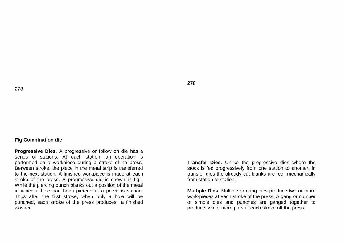
278 Fig Combination die Progressive Dies. A progressive or follow on die has a series of stations. At each station, an operation is performed on a workpiece during a stroke of he press. Between stroke, the piece in the metal strip is transferred to the next station. A finished workpiece is made at each stroke of the press. A progressive die is shown in fig . While the piercing punch blanks out a position of the metal in which a hole had been pierced at a previous station. Thus after the first stroke, when only a hole will be punched, each stroke of the press produces a finished washer.
278 Transfer Dies. Unlike the progressive dies where the stock is fed progressively from one station to another, in transfer dies the already cut blanks are fed mechanically from station to station. Multiple Dies. Multiple or gang dies produce two or more work-pieces at each stroke of the press. A gang or number of simple dies and punches are ganged together to produce two or more pars at each stroke off the press.

5. What is deep Drawability? Explain about redrawing ? Deep Drawability: Deep drawability or drawing ration of a metal is defined as the reaction of the maximum blank diameter to the diameter of the cup drawn from the blank (usually taken to be equal to the punch diameter), i.e. D/d. for a given material there is a limiting drawing ratio (LDR) , after which the punch will pierce a hole in the blank instead of drawing the blank. This ratio depends upon many factors, such as type of material, amount of friction preset, etc. The usual range of the maximum drawing ratio is 1.6 to 2.3. A simple push through drawing die is shown in fig (1) the drawing punch must be properly vented with drilled passages. Venting serves double purpose. It eliminates suction which would hold the cup on the punch and damage the cup when it is stripped from the punch. Secondly, venting provides passages for lubricants. 285 Fig. (A) Deep drawing operations.
Fig. A simple push through drawing die.
As already discussed, the presses used for deep drawing are: double action cam press or double action toggle press. Many presses used for deep drawing operations are hydraulically operated and these presses have an additional hydraulic cylinder and piston for the additional slide.
Product applications of deep drawing process are: Cups, shells, short tubes, automotive bodies, gas tanks, appliance covers and household hardware (spoons, utensils etc.), beverage cans scamless can bodies. Redrawing. In deep drawing, the percentage reduction in one draw is defined as:
D-d% reduction = 100
D
Dnow 1.6 to 2.3
d
d 0.435 to 0.625=0.50(average)D
The average reduction in deep drawing
d = 1 100
D
=
=
−
=50%
To make tall cups of smaller diameter (such as
cartridge cases and closed – end tubes). It is necessary to use successive drawing operations. Reducing a drawn cup to a smaller diameter and increased height is known as

“Redrawing “. The two methods used for redrawing are: direct redrawing and indirect or reverse redrawing.
Fig. (a and b) are direct redrawing methods. In fig. (a), the metal bends twice inducting high strain hardening in it. Fig. (b), the metal again bends twice, but the angle through which it bend is less than 90o. This reduces strain hardening as compared to fig. (a) and punch load is reduce. But he drawback is that the initial drawn cup must be made with a taper corner. 286 Fig. Redrawing
In reverse drawing, (fig(c)), the basic phenomenon that a cold – worked material exhibits greater ductility when the deformation direction is reversed in successive operations (strain softening) is made use of.
Redrawing is extensively used for food containers, fountain-pen caps, oil filter housings and shock absorber pistons etc.
Practical reductions in diameter for successive redraws are : 30,25, 16 and 13%. Metal becomes work-hardened as it is drawn and redrawn and must annealed to prevent failure before it reaches its limit. 6. Define bending. Explain different bending method? Bending:
Bending is the metal working process by which a straight length is transformed into a curve length. It is a very common forming process for changing sheet and plate into channels, drums, tanks etc. During the bending operation, the other surface of the material is in tension and the inside surface is in compression. The strain in the bent material increases with decreasing radius of curvature. The stretching of the bend causes the neutral axis of the section to move towards the inner surface. In most cases, the distance of the neutral axis from the inside of the bend is 0.3 t to 0.5t, where ‘t’ is the thickness of the part. Bending terminology is illustrated in fig. 287 Fig Ironing

Fig. Bending Terminology. 287 Bending Methods. The three bending methods commonly used are: V-bending, Edge bending, and U-bending (channel bending) V- Bending. In V-bending, a wedge- shaped punch forces the metal sheet or strip into a wedge shaped die cavity. (fig.) The bend angle may be acute, 90o or obtuse. As the punch descends, the contact forces at the die corner produce a sufficiently large bending moment at the punch corner to cause the necessary deformation. To maintain the deformation to be plane-strain, the side creep of the part during its bending is prevented or reduced by incorporating a spring loaded knurled pin in the die. The friction between the pin and the part will help to achieve this, (fig). Plane strain conditions will also be established in the centre of the sheet if its width is more than 10 time its thickness.
287 Fig. V-Bending.

Edge Bending: In edge bending, fig. a flat punch forces the stock against the vertical face of the die. The bend axis is parallel to the edge of the die and the stock is subjected to cantilever the movement of the stock during bending, it is held down by a pressure pad before the punch contacts it.
A V-bending die and U-bending die are shown in fig. respectively. Stripper pins are provided to shed are provided to shed the part form the punch. 288 Fig.
289

7. Write short notes on a) Spring back. b) Press Brake Spring back. At the end of the bending operation, when the pressure on the metal is released. There is an elastic recovery by the material. This causes a decrease in the bend angle and this phenomenon is termed as spring back. For low carbon steel, it can be 1o to 2o and for medium carbon steel, it can be 3o to 4o, for phosphor bronze and spring steel the spring back can be from 10 to 15o. To compensate for spring back, the wedge-shaped punches and the mating dies are made with included angles somewhat less than required in the formed component. Due to this, the component will be bent to a greater angle than desired, but it will spring back to the desired angle. For other types of bending, the part is over bent by an angle equal to spring-back angle by having the face of the punch undercut or relived. The values of spring back given above are for 90o bends and are usually greater for grater angles. 289 Fig. Edge bending
Press Brake. The bending methods discussed under Art. Refer to bent parts with short lengths. These parts can be bent at high rates in mechanical presses in dies. For longer lengths, presses with very long and narrow beds (9m long or even more) are used. Such a press is called as “Press brake”. The press brake is chiefly used to form long, straight bends in sheets and plates to produce structural shapes such as angles channels automobile and truck chassis, and corrugated sheets. The metal is bent between interchangeable dies attached to the bed and the ram. By using different dies, many types of bends may be obtained, (fig. ). 290 Fig. Press brake forming. Fig. shows a typical mechanical press brake and a hydraulic press brake constructed by HMT.

8. Explain details about rubber press forming. Rubber- Press Forming. Rubber-press forming or Rubber- pad forming is a sheet metal forming (bending and stretching or drawing) operation in which either the punch or the die is a piece of constrained elastomer (rubber or polyurethane). The basic principle of the process is that if a block of rubber or polyurethane is placed in a cylinder and pressure is brought to bear upon it by applying a force by a ram of a press, any such force must develop a resultant reaction on every surface with which the elastomer comes in contact. This resultant reaction force is used for forming sheet metal to the required shape using form blocks or punches or dies. Fig. shows a schematic view of Rubber – press forming operation. Rubber is restrained from side ward motion and acts as a deformable female die to exert essentially hydrostatic pressure on the Workpiece. 291 Fig. Rubber – press forming.
291
This process is becoming increasingly popular for short run production because of its economy since it eliminates the need for the more expensive mating steel dies. The process has got the following advantages:
1. Tools have fewer components and are made of cheap and easy to machine materials.
2. One rubber pad takes the place of many different die shapes.

3. The forming radius decreases progressively during forming unlike the fixed radius on conventional dies, thereby allowing greater depth of draw in one stroke (draw ratio up to 2.7).
4. There is almost no thinning of the work material. 5. Tool setting time is greatly reduced. 6. The variation in sheet thickness is not a limitation as
in conventional drawing, since only one tool is used in rubber pad forming.
The limitations of the process are:
1. Rubber pads wear out rapidly. 2. Details of the components formed are less sharp as
compared to conventionally formed components. 9. Write notes on a) Rubber hydroform process b) Hydromechanical forming. Rubber Hydroform process. In this process, which is a variation of rubber – press forming process. A pressurized liquid behind the rubber pad is used to exert the force required for forming fig. shows one such set up. The rubber pad or diaphragm acts as a seal at the end of the liquid container. The part to be formed is wrapped on to the punch due to high hydrostatic pressure developed which acts equally all over the surface of the sheet when the container descends over the punch. Since hydrostatic pressure acts equally all over the surface, deeper cups and complex shapes with sharper details can be achieved.
291 Fig. Rubber Hydroform process. 292 Fig. Hydromechanical forming.

Hydromechanical Forming. This process is a modification of rubber hydroform process. Here, the container containing the liquid (oil) is fixed on the bed of the press and the rubber pad or diaphragm acting as a seal is not used. The blank which is directly placed on the draw ring acts as the sealing element. Fig. Blank holder descends on the blank and applies the blank holding pressure. As the punch travels into the container, the cup is formed against the hydrostatic pressure developed inside the container. This enables the formation of deeper cups and complex shapes. In this process, since the rubber is not used, the associated problems of wear and replacement etc. do not arise. 10. Discuss about any two spinning processes. Metal Spinning. Spinning is one of the oldest methods of sheet metal forming. Parts that have circular cross-sections can be made by spinning from sheet metal. The method involves the forming of a work pieces over a rotating from block or chuck held in a special lathe, fig. A smooth, hardened, rotating or stationary tool is held by the operator and is pressed against the blank to progressively bend the work piece to conform to the chuck or mandrel. The mode of deformation of the metal during spinning is a mixture of bending and stretching, making the process mot suitable for shaping of hollow parts from ductile metals and alloys. The thickness of the spun part is nearly the same as the thickness of the under formed blank. The thickness of the blank is upto 6mm for soft non-ferrous metals and upto 5mm for low carbon steel. Spinning speeds vary form 1.5m/s for small parts to 25m/s for large-diameter parts.
Spinning has been used to produce parts more than 3.6m in diameter. Before spinning, a suitable lubricant should be applied to the surface of the metal. Soap, beeswax, white lead and linseed oil are commonly used for this purpose. The degree of deformation obtainable by spinning depends upon the shape of the finished part, the material, the lubricant, and particularly the skill of the operator. 293 Fig. Metal spinning
Product applications of spinning are: reflectors, kitchenware, bells on musical instruments, light fixtures, funnels and large processing kettles radar dishes, roket motor cases.

The special features of metal spinning are:
1. Low equipment cost. The equipment consists of a speed lathe to the chuck of which the form block is attached. The blank is held between the form block and a tail plate.
2. Low tool costs. The form block may be of plaster,
wood or metal. 3. some complex parts of re-entrant shape (kettles,
pitches) can be very economically produced by spinning.
The drawbacks of the method are:
1. The method depends to large extent on the skill of the operator.
2. Finished parts are not always uniform and close
tolerance cannot be obtained.
(a) Power spinning.
In manual spinning, the skill of the operator plays an important role in getting components of required quality. Also, manual spinning of metals having thickness of more than 1mm and with complicated contour is difficult to shape. Hence, in order to obtain the economic advantage of spinning and at the same time to reduce the skill required of the operator and to spin thicker metals, spinning machines have been evolved. In these machines, the action of the spinning roller is controlled mechanically (tracer mechanism) or under NC control. This is called as Power spinning.

HMT has developed a Flow Turning Lathe FTL 40,
which can be used for power spinning also. It is a
semiautomatic spinning and flow turning machine with a
hydraulic copying attachment. The forming/spinning cycle
of the machine is automatic, but the loading and unloading
of work pieces is manual. The machine consists of a head
stock, a hydraulically operated tailstock, and slides
mounted on an auxiliary bed which is fixed to the main
bed. A circular blank is held between the tailstock quill and
the spinning mandrel (form block) and the metal is shaped
to the required form in a single or multiple templates
respectively. There is very little change in the metal
thickness and no limitations in the shape of the parts.
When the roller control mechanism is set for a particular
part, each successive part will then be spun in the same
manner.
(b) Comparison of Spinning and Deep Drawing.
Metal spinning is both supplementary and
competitive with drawing in presses. Due to its low tooling
and equipment costs, spinning is normally used for low
volume production. But drawing is preferred for mass
production (due to high cost of dies and presses) to
reduce the production cost of the component. Labour
costs are higher for manual spinning than for press work.
Also, production rates are much less. However, as the size
and complexity of the part increase, the spinning process
becomes more competitive.
(c) Hot spinning.
Hot spinning of metals is used commercially to dish
or form thick circular plates to some shape over a
revolving form block. A blank of sheet metal is clamped on
centre against a form block or chuck, which

is revolved on the spindle of a lathe. A rounded stick or
roller is pressed against this revolving piece and moved in
a series of sweeps. This displaces the metal in several
steps to conform to the shape of the chuck. The pressure
may be applied by hand or mechanically. A hot spinning
machine is a combination of a vertical press and a large
vertical spinning lathe which rotates the blank about a
vertical axis. Power actuated rollers do the forming, as the
part is rotated. Metal upto 150mm thick is routinely hot
spun into disched pressure vessels and tank shapes.
Thinner plats of hard to form metals like Titanium are also
shaped by hot spinning.
Flow turning. This method is used form conical, conical, cylindrical, parabolic and hemispherical shapes, Unlike power spinning, where there is no significant change is section thickness of the work material, in flow turning, (fig. ) the metal in plastically deformed and progressively displaced under the compressive forces of a pressure roller. The metal flow is entirely by shear. The thickness of the blank gets reduced to the required amount, resulting in an increase in length. However, the diameter of the blank remains unchanged. The thickness of the finished part will be given as: Fog conical parts, thickness of finished part=
Thickness of blank sin
If is less than 30o, the part is finished in more than one stages with an anneal between the stags. Upto 80% reduction in metal thickness can be achieved. 294 Fig. Flow Turning
The method is also known as “Shear forming”, “Shear spinning” or “Spin forging”. The method can also be used to reduce the thickness of the tube or to produce tubes of multiples diameters, (fig) then the method is called as “Tube spinning”.
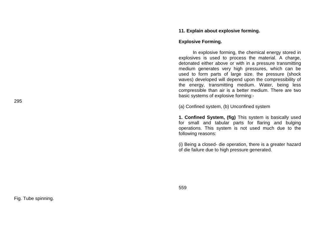
295 Fig. Tube spinning.
11. Explain about explosive forming. Explosive Forming.
In explosive forming, the chemical energy stored in explosives is used to process the material. A charge, detonated either above or with in a pressure transmitting medium generates very high pressures, which can be used to form parts of large size. the pressure (shock waves) developed will depend upon the compressibility of the energy, transmitting medium. Water, being less compressible than air is a better medium. There are two basic systems of explosive forming:- (a) Confined system, (b) Unconfined system 1. Confined System, (fig) This system is basically used for small and tabular parts for flaring and bulging operations. This system is not used much due to the following reasons: (i) Being a closed- die operation, there is a greater hazard of die failure due to high pressure generated. 559

Fig. Explosive forming (confined system) (ii) Die erosion is a big problem.
In this system, a dies in two or more pieces is used which completely encloses the Workpiece. When the explosive is detonated, a stock wave is produced in the energy transmitting medium (in this case, air) which forces the Workpiece into the die. Vacuum should be created in between the die and the Workpiece, otherwise, the trapped air will be subjected to virtually adiabatic compression, resulting in very high temperature which can burn or melt the work piece or the die. The tapped air will also prevent the complete forming of the part. 2. Unconfined system, fig. This system is used for forming large parts from very thin sheet metal upto large ship plates about 25mm thick. This method has been used for many years in ship building. The work piece or blank is clamped to the die and the entire die-work assembly is lowered into a swimming pool. An explosive is denoted above or within the water. The shock waves are produced in the body of water (energy transmitting medium) which in turn forces the Workpiece into the die. Again, vacuum should be drawn in between the Workpiece and the die.
The important process variables are: type and amount of explosive, the distance between the explosive and Workpiece, the type of energy transmitting medium, and the Workpiece.
560 Fig. Explosive forming (unconfined system) Use of water as the transmitting medium has the following advantages:
1. Since air is very much more compressible than water, the shock pressures produced are very much lower.
2. with water, the noise level of explosion is reduced. 3. Possibility of damage to the *workpiece form
particles of explosive e and detonator is greatly reduced.
Basically two types of explosives are used.:
1. Low pressure explosives or firing explosives, such as smokeless powder and black powder. With low pressure explosives, known as cartridge system, the expanding gas is confined (confined system) and the pressure may built upto 700MPa.
2. High pressure explosives or detonating explosives. The most widely used detonating materials are:- dynamite, amatol, TNT (tri-introtoluene), RDX(Cyclotrimethylenetrinitrimine), Tetryl and PETN (Pentaerythriol tetranitrate) and their mixtures with detonating materials which are preferred for explosive forming process (unconfined system), the gas pressure may be upto 20 times of that for low pressure explosives. The approximate deformation velocities range from 9 to 230m/s.
The distance between Workpiece and explosive charge
(called as “Stand off” distance) or that between the explosive and the water level is also important, since, if the latter distance is small, the shock waves could vent to the surface and lose much of their energy. Greater force can be exerted on the Workpiece if the “stand off” distance is smaller. Thus, small stand offs are used for deep drawing the large stand offs for shallow drawing. A too small a stand-off distance will result inn excessive local deformation and thinning of the Workpiece
The evaluation of the efforts of stand – off distance are usually (normally) based on the criterion that the optimum distance is that at which a central charge will produce the
maximum deformation in free forming. Since the optimum distance depends on several factors such as the type of explosives used and the geometry of the tank-workpiece system, it is not possible to define a universal optimum distance. However, as a general guide, where a single point charge is used, the stand- off distance is given as, S=diameter for circular jobs of relatively small dimensions, say less than 60cm. =should be decreased to the order of 0.5 diameter for larger jobs.
The distance ‘S’ has a marked effect on the shape of freely formed parts. Generally, the greater S, the more nearly conical is the formed shape. As S is decreased to the order of 0.2 diameter of the Workpiece, a more rounded shape approaching an ellipsoid or segment of a sphere is produced.
It has been suggested that for high efficiency, the depth of water over the explosive should be at least twice the stand-off distance. In explosive forming, spring back is minimized. Less spring back occurs with:
(i) The use of sheet explosives close to the Workpiece.
(ii) High clamping forces on the hold down areas.
(iii) The absence of lubricant.

Thick materials exhibit less spring back than do parts made from thin blanks.
Depending on the number of parts to be made, the die-material can be : concrete, wood, epoxy, plastic, plaster of paris, C.I., steel aluminium alloys and various composite materials. Because of the nature of the process, safety is a very important consideration. The various die materials with their areas of application are given below: Concrete: Medium pressure Cast Iron (ductile) : High pressure and many parts. Concrete and epoxy resin: Low pressure and large parts. Concrete and fibre glass: low pressure and large parts. Kirksite: Low pressure and few parts Kirksite: and fibre glass: Low pressure and few parts. Explosive forming has got the following fields of application:
1. For the production of components having a wide- range of sizes and shapes, like radar dishes, and rocket motor cases etc.
2. The capital cost being low and the rate of output limited, the method is economically suitable only for low volume production and for the production of prototype parts.
3. For the production of very large parts with re-entrant sections, which are not possible by conventional methods.
UNIT - V
PART - A
1. Define polymerization. The process of linking together of monomers, that is of obtaining macromolecules is called polymerization. 2. Write the classification of plastics. Plastics fiber and elastomers are classification of plastics 3. Define plastics.
Plastics is a term applied to compositions consisting of a mixture of high moleculer compounds are fillers, plasticizers etc. 4. What is a thermosetting plastic?
These plastics undergo a number of chemical change on heating and cure to infusible and practically insoluble articles. 5. What is a thermoplastic? These plastics soften under heat, harden on cooling, and can be registered under heat.

6. List the properties of plastics.
- Good damping capacity - Good surface finish of the product. - Good chemical stability. - The high heat and electric insulation of plastics
permits them to be applied in the radio and electrical engineering industries.
7. List the disadvantages of plastics.
- Comparatively higher cost of materials. - Inability of most plastics to withstand even
moderately high temperatures. 8. Define compression moulding.
In this process, a premeasured quantity of plastic in the form of particles or briquettes, is placed in a heated mould and compressed at suitable pressure and temperature. 9. Define transfer moulding.
It is the modification of compression moulding in which the material is first placed in a separate chamber from which it is pushed through an orifice in to the mould cavity as the mould closes. 10. List the advantages of transfer moulding.
- There is little pressure inside the mould cavity until it is completely filled at which stage the full liquid pressure to transmitted.
- The plastic acquires uniform temperature and properties in the transfer pot prior to transfer.
11. Define calendaring.
It is an intermediate process where the extruded plastic sections are reduced to sheet which may or may not them be formed to find shape by vaccum forming. 12. List the uses of calendaring. Rain wear, shower, curtains, taps, trays, credit, cards, lamination. 13. Define rotational moulding.
Uses gravity inside a rotating mould to achieve a hollow form. Also remoulding, it is alternative to blow moulding for making large, hollow shapes. It is used principaly for thermoplastic polymers, but applications for thermosets and elastomers are becoming more common. Rotomoulding tends to favour more complex external geometries, large parts, and lower production quantities than blow moulding. 14. List the uses of rotational moulding. Boats, large containers, laminated petrol tanks for motor cars.

15. Define blow moulding.
In this process a hot extended tube of plastic called a parson is placed between the two part open mould. 16. Define vacuum forming.
It is a process in which a heated plastic sheet is changed to a desired shape by causing it to flow against the mould surface by reducing the air pressure between one side of the sheet and the mould surface. 17. Define compression moulding.
Compression moulding is the equivalent of closed dig forging. In this process a premeasured quantity of plastic in the form particles or briquettes is placed in a heated mould and compressed at suitable pressure and temperature. 18. What is positive mould? When the plastic is completely trapped between the male and female die, it is called as positive mould. 19. List the uses of injection moulding. It is used for making parts with complex threads and intricate shapes, thin – walled parts etc.
20. Give the draw back of extension process.
Major draw back of this type of machine is the reciprocating action of the ram which is time wasting since the ram must be with drawn after its power stroke. 21. Define fillers. A filler is used to economize on the quantity of polymer required or to vary the properties to some extent. 22. What is catalysts. These are usually added to promote faster and more complete polymerization. 23. What is the use of dyes and pigments. These are added in many cases, to impart a desired colour to the material. Ex: Iron oxides, carbon 24. Define plasticizers.
Plasticizers are liquids of high boiling point and low molecular weights which are added to improve the plastic behaviour of the polymer.

PART - B
1. Define plastics. Explain details about types of plastics with properties.
Polymers can be divided into three broad divisions: plastics, fibers and elastomers (polymers of high elasticity, for example, rubber). Synthetic resins are usually referred to as plastics. Plastics derive their name from the fact that in a certain phase of their manufacture, they are present in a plastic stage (that is , acquire plasticity), which makes it possible to impart any desired shape to the product. Plastics fall into a category known chemically as high polymers.
Thus, “ Plastics” is a term applied to compositions consisting of a mixture of high – molecular compounds (synthetic polymers) and fillers, plasticizers, stains and pigments, lubricating and other substances. Some of the plastics can contain nothing but resin (for instance, polyethylene, polystyrene). Types of plastics: Plastics are classified on the broad basis of whether heat causes them to set (thermosetting) or causes them to soften and melt (thermoplastic). 1. Thermosetting Plastics. These plastic undergo a number of chemical changes on heating and cure to infusible and practically insoluble articles. The chemical change is not reversible thermosetting plastics do not soften on reheating and can not be reworked. They rather become harder due to completion of any left-over
polymerization reaction. Eventually, at high temperatures, the useful properties of the plastics get destroyed. This is called degradation. The commonest thermosetting plastics are: alkyds, epoxides, melamines, polyesters, phenolics and ureas. 2. Thermoplastic Plastics. These plastics soften under heat, harden on cooling, and can be resoftened under heat thus, they retain their fusibility, solubility and capability of being repeatedly shaped. The mechanical properties of these plastics are rather sentitive to temperature and to sunlight and exposure to temperature may cause thermal degradation. Common thermoplastic plastics are: acrylics, poly tetra fluoro ethylene (PTFE),polyvinyl chlorides (PVC), nylons, polyethylene, polypropylene, poly styrene, etc.
Thermo setting plastics are cross-linked polymers and the thermoplastics. Since they do not soften when heated and roasted or charged at high temperatures, thermosetting plastics have applications only in moderate service temperatures, for example, saucepan handles. Thermoplastics are reclaimable while thermosetting plastics are not. Properties of plastics. Their great variety of physico chemical and mechanical properties, and the ease with which they can be made into various articles have found plastics their wide application in the engineering and other industries.

1. Their comparatively low density (1 to 2 g/cm3), substantial mechanical strength and high anti friction properties have enable plastics to be efficiently used as substitute for metals, for example, non-ferrous metals and alloys-bronze, lead, tin, babbit etc., for making bearing. 2. With certain special properties (silent operation, corrosion resistance etc.), plastics can sometimes replace ferrous metals. 3. From the production point of view, their main advantage is their relatively low melting points and their ability to flow into a mould. 4. Simple processing to obtain machine parts. Generally there is only one production operation required to convert the chemically manufactured plastic into a finished article. 5. In mass production, plastics substituted for ferrous metals allow the production costs to be reduced by a factor of 1.5 to 3.5 and for non-ferrous metals by a factor of 5 to 20. 6. Good damping capacity and good surface finish of the product. 7. The high heat and electric insulation of plastics permits them to be applied in the radio and electrical engineering industries as dielectrics and as substitutes for porcelain, ebonite, shellac, mica, natural rubber, etc.
8. Their good chemical stability, when subjected to the action of solvents and certain oxidizing agents, water resistance, gas – and steam- proof properties, enable plastics to be used as valuable engineering materials in the automobile and tractor, ship building and other industries.
With the development of high – performance engineering plastics, they are successfully competing with other engineering materials. They are replacing sheet metal parts, zinc and A1 alloy castings and C.I. they are being increasingly used in automobile industry, where weight reduction is one of the means of fuel economy. The initial use of plastics in this direction was for fascia panels, interior fittings, and other non- load bearing components. Now structural parts such as bumpers, brake fluid tanks and some body parts are also being made of plastics. Disadvantages: 1. Comparatively higher costs of materials. 2. Inability of most plastics to withstand even moderately high temperatures. The properties and uses of common thermoplastics and thermosetting plastics have been given in chapter2(Table.)

2. Explain about injection moulding . Processing of Thermoplastic plastics
Thermoplastics can be processed to their final shape by moulding and extrusion processes. However, extruding is often used as an intermediate process to be followed by other processes, for example, vacuum forming or machining. Injection Moulding:
An important industrial method of producing articles of thermoplastics is injection moulding, The process is essentially as follows:
The moulding material is loaded into a hopper from which it is transferred to a heating section by a feeding device, where the temperature is raised to 150oC – 370oC. and pressure is built up. The material melts and is forced by an injection ram at high pressure through a nozzle and sprue into a closed mould which forms the part.
The mould is in at least two sections, so that it may be split in order to eject the finished component. For the process to be competitive, the mould must be fairly cool(between ambient temperature and the softening point of the plastic) and consequently the mould must cooled by circulating water.
603 Fig. Injection moulding process.
The improvement to the ram type injection moulding machine lies in the separation of the plasticizing and filling actions. The single – screw pre-plasticizer is probably the most successful design for injection moulding machines, The rotation of the screw provides the plasticizing action by shearing and frictional effects and the axial motion of the screw provides the filling action. 604 Fig. Screw Injection Moulding Machine.

Injection moulding machines have a high production capacity: some can produce from 12 to 16 thousand parts per shift. This method is suitable for making parts with complex threads and intricate shapes, thin-walled parts etc.
Injection moulding machines range in size form an
injection capacity of 12,000mm3 to 2.2106 mm3. The locking forces are applied to the mould usually by hydraulic means, and may vary from 0.1 MN to 8.0 MN or even more. The injection pressure may range from 100 MPa to 150MPa. 3. Discuss about the extrusion process of plastics. Extrusion Process:
The extrusion process, in many cases, produces material in an intermediate form for subsequent reprocessing to its final component form. The process is the same as for metals, that is, the expulsion of material through a die of the required cross-section. The earliest extrusion machines were of the ram type. The cylinder of the machine (container) is filled with prepared plastic and extruded through a die under the pressure of the ram. The advantages of this machine are: simplicity in operation and a controlled pressure which can be virtually as high as required. If the polymer can be plasticized by pressure, then the ram extruder is advantageous in view of its simplicity. But for plastics which require heat, the separate pre- processing may be regarded as a draw back. Another major drawback of this type of machine is the reciprocating
action of the ram which is time wasting since the ram must be withdrawn after its power stroke and a new dolly of material inserted in the container. Also, with many materials, the die orifice must be cleaned between each working stroke.
Nowadays, the ram machine is mainly used for “wet extrusion” that is for extruding plastics which have been softened by the addition of solvents. Although useful in homogenizing materials which contain hard inclusions, wet extrusion has the disadvantage of producing a component from which the solvent has to be removed.
For the extrusion of plastics, single-screw machine has completely replaced the ram type machine. There are two basic types of screw extruders: the melt extruder and the plasticizing extruder. In the former the material is delivered to the extruder already melted and thus the function of the extruder is merely to push the material to the die and through the orifice. In the plasticizing extruder the material is in the form of granules or particles and so the extrude has to compress and work it until it melts before delivering it, under pressure, to the die orifice.
Fig illustrates a screw type extrusion machine. It consists of: a water cooled screw having a special thread form to suit the material being extruded; and a barrel in which the screw rotates (including a form of heating in the case of a plasticizing extruder); and an extrusion die.

605 Fig. Screw-extrusion Machine.
The material is fed from a hopper through a port in the cylinder where the rotation of the screw imparts both axial and rotary motion to the particles. The restricting effect of the die at the far end builds up a pressure in the particulate mass which is then worked by shearing and heated by frictional effects until it is in a plastic state and cant be extruded.
4 . Write notes on a) Compression moulding. b) Transfer moulding Compression moulding:
Compression moulding, (fig.) is the equivalent of closed – die forging. In this process, a premeasured quantity of plastic in the form of particles or briquettes, is placed in a heated mould compressed at suitable pressure and temperature. Hydraulic presses are usually employed to provide the pressure (which may range from 20 to 30 MPa or even higher upto 80MPa in some cases) for compressing the plastic compound. Other equipment, such as friction and screw presses, can also be used. The object of compression moulding is to bring the plastic to virtually molten state. Thus the process is, effectively forming ram the liquid state, the material being held in the mould until the curing stage is over when polymerization is complete. The process is rather slow with the phenolies and urea resins, but some of the newer resins have shorter curing times and this has improved the production rates appreciably. 606 Fig. compression Moulding

When the plastic is completely trapped between the male and female die, it is called as “positive mould” Closer tolerances can be held if a small flash is allowed to extrude, usually along the male die permeter in “Semipositive moulds”. Die forging. Transfer Moulding: Transfer moulding is a modification of compression moulding in which the material is first placed in a separate chamber (transfer pot), from which it is pushed through an orifice (sprue) into the mould cavity (by the action of a punch) as the mould closes. The material to be moulded is often pre- heated by radio – frequency methods and, where it is desired to improve toughness and strength, reinforcing fillers may be used. The process has got the following advantages. 607 Fig. Transfer Moulding
1. There is little pressure inside the mould cavity until it is completely filled, at which stage the full liquid pressure is transmitted. 2. The Plastic acquires uniform temperature and properties in the transfer pot prior to transfer. The plastic is further heated by shearing through the orifice, viscosity is reduced, and the plastic fills the intricate mould cavities. 5. Write notes on a) Calendering b) Rotational moulding c) Blow moulding Other processing methods for Plastics 1. Calendering:
It is an intermediate process where the extruded plastic sections are reduced to sheet which may or may not. Then be formed to final shape by vacuum forming. It is clear that the calendaring process cab be used only for thermoplastics and not for thermosetting plastics.
Calendering is in some ways similar to rolling process in that the material is compressed between rolls and emerges as sheet, (fig.a)

609 Fig. Calendering process
However, there are differences. There is appreciable thickening after the material has reached minimum thickness at the roll gap and the pre-calendered material is not in sheet form, but of indefinite shape. The method of producing wide sheet and foil is illustrated in fig. b. The thermoplastic melt is red to a multiroll calendar. The first roll gap serves as a feeder. The second as a metering device, and the third roll gap sets the gauge of the gradually cooling plastic which is then wound, with about 25% stretching onto a drum.
Calendering is a high- production rate (typically 100m/min) process, mostly for flexible PVC, for example, upholstery, rainwear, shower curtains, tapes, etc. and rigid PVC, for example, trays credit cards, laminations. PVC is also calendered into the well known transparent film widely used for packing. 2. Rotational Moulding: In this process, also called “rotomoulding”, large relatively thin – walled hollow (open or closed) parts are made. A measured quantity of polymer powder is placed in a thin- walled metal mould. The mould is closed and is rotated about two mutually perpendicular axes as it is heated. This causes the powder to sinter against the mould walls, building up the wall thickness of the components. At the end of the heating and sintering operations, the mould is cooled while it is still rotating. Cooling is done by applying cold water and air to the outside of the rotating mould. The rotation is then stopped and the component is removed. To increase production rates, three moulds at the end of three arms joined together to the central spindle (just like centrifuge casting) are used, with one mould for each stage of the process, that is, load – unload, heat and cool positions.
The process is simple as no pressure is employed and the part is free of moulded in stresses. The technique is extensively used for the production of toys in P.V.C. such as boats, horses etc. Large containers of polyethylene petrol tanks for motor cars are made from polythene (outer shell) and nylon (inner shell).

3. Blow Moulding: In this process, a hot extruded tube of plastic, called a parison, is placed between the two part open mould. Fig. a. The two halves of the mould move towards each other so that the mould closes over the tube. The tube gets pinched off and welded at the bottom by the closing moulds, (fig. b). The tube is then expended by internal pressure, usually by hot air, which forces the tube against the walls of the mould, (fig. c) the component is cooled and the mould opens to release the component, (fig. d). 610 Fig. Blow Moulding.
6. Discuss about continuous extrusion process of plastics. EXTRUSION
Extrusion means the continuous flow of material through a die. Extrusion moulding is used mostly for the production of sheet, tube bar and typical applications, in thermoplastic materials. Granulated powder made of such materials as vinyl resins, cellulose derivatives, nylon, polyethylene and polypropylene make up the material s used in the process. 451 Figure Continuous extrusion
Plastic extrusion machine consists of a hopper into which the powder or pellets are fed into a heated cylinder, the screw feeding mechanisms, a nozzle and the die assembly. The rotating screw carries the heated plastic forward and forces it through heated die orifice of the
required shape. As it leaves the die, it is gradually cooled by carrying it through cooling media while resting on a conveyor, it is then wound into coils or cut to desired lengths.
There are advantages to the extrusion process. The tooling is low cost compared to injection moulding. Material thickness can be accurately controlled. In addition, production rates are high and intricate profiles can be produced. 7. Write notes on a) Thermo forming. b) Blow moulding.
Thermoforming sometimes called vacuum forming, is the shaping of hot sheets or strips of thermoplastic materials into a desired shape either by mechanical or pneumatic methods. The sheets of plastic used in the thermoforming process are produced by extrusion, calendaring or pressing. Thicknesses of the sheets tat are processed range from 0.125 to 3.2mm or even greater.
The basic process is quite simple. A piece of plastic sheet is clamped into a frame. The plastic is heated, usually with electric heaters, until it begins to sag. Vacuum, air or mechanical pressure is then applied through small holes in the mould and the plastic is rapidly pulled tightly against the mould creating close profile conformity. The frame is raised, the part is removed and then trimmed in a punch press. The mould may have several shapes, for the same part or for different parts.
In vaccum forming the sheet is clamped in a stationary frame and the heated sheet is vaccum-drawn into the mould. 453 Figure Thermoforming (methods of forming sheets)
A male mould is used in drape vaccum forming and a moveable frame or clamp drapes a heat – softened sheet over the male mould before vacuum is pulled. A more complex shape can be developed by this method.
In the vacuum snap back process in the first step, vaccum is produced in the chamber and the sheet is drawn down into the cavity. The male plug descends and clamps against the chase which holds the sheets. In the second step, vacuum is applied to male plug and the material is drawn to the mould. Deep drawn parts with generous tapers and corners with large radii are possible with this technique.
Among the items made by thermoforming process are small jelly containers used in restaurants, luggage, refrigerator inner panels lighting fixture, helmets and containers for packing.

Blow Moulding
Blow moulding is a process of placing a softened thermoplastic closed – end tube (parison) and applying air pressure to inflate it.
In operation, the heated parison is continuously extruded, cut to the proper length and sealed at one end, gripped in the two – piece mould and then air is injected to force the plastic against the walls of the water – cooled mould. The part cools and then the mould is opened and the part is removed. 453 Figure stages in blow moulding
Production methods range from simple manual operations to relatively complicated automatic ones. Blow moulded products include bottles, floats, automobile heater ducts and similar articles.
8. Explain details about types of Plastics with properties and uses. TYPES OF PLASTICS Majority of plastics are organic substances or resins containing carbon as central element together with oxygen, hydrogen, nitrogen, chlorine, etc. The properties of plastics depend on the atoms it contain and the way in which these atoms are arranged in molecules. These organic compounds are also known as polymers. One major class of plastics called the Thermoplastic materials, composed of separate long molecules arranged side by side (synthesized in the shape of long threads). Thermoplastics become soft when heated and re-harden on cooling because the molecules are held together by secondary bond. The strength of these forces between separate particles of matter depend directly upon the masses and inversely upon a power of distances between the molecules. This explains why plastics of large molecules are strong and tough. Strong associative forces tend to make plastics brittle at low temperatures. Heat increases, atomic movement, separates the molecule, reduces the associative force and thus softens thermoplastics. Molecules with side branches cannot be packed closely and the material is not so strong but generally is soft and flexible. A second major class of plastics called Thermosetting materials is composed of long molecules linked to each other in three dimensions by primary bonds.

These bonds are not broken by heat until the compound is decomposed. Thermosetting plastics are therefore generally stronger, harder, more resistant to heat and solvent and lower in material cost. The secondary bonds of the thermoplastic materials allow deformation and flow under stress. i) Thermo Plastics:
They when heated even at 40C become soft and so can be remoulded without any change in structure. They can be ground up and remoulded, i.e. they can be re-shaped while in soft state. Usually, they become soft at
about 65C to 315C and can flow to an appreciable extent underload. And that is why most of the plastics used today are themoplastics. Today numbers of thermoplastics are available into the market such as nylons, polyetheline resins, polystyrene, polyropylne, polycarbonate, acrylic resins, vinyl plastics, etc. Amongst them nylons, acrylics and vinyl plastics are commercially extensively used and therefore some of their properties are outlined and herein table.
Table
Thermoplastic type
Properties Use
1. Polyethylene Both flexible and rigid types are lightly break resistant, unaffected by food acids, and household solvents, resist moisture, flexible over a wide range of temperatures.
Widely used as a coating for paper and paper-board, film packaging, disposable bags, furniture components, etc.
2. Polyropylene Good dimensional stability, Appliance housings,
Resistance to heat, chemicals, moisture, electricity, easy to process. Good impact resistance.
refrigerator door liners, wall tiles, battery cases, toys insulators, ornaments, etc.
3. Polystyrene Rigid, clear, transparent materials with good tensile strength, good combination of rigidity and touchness; good mouldability.
Wide applications in packaging, appliances; housewares; furniture; dentalplates; auto parts.
4. Polyvinyl Chloride (P.V.C)
Chemical and abrasion resistance, good weather ability, easily prigmented; good resistance to petroleum-based-solvents, acids, etc.
Sound records, blown bottles, rigid sheeting, upholstery, hose, flooring, rain-wear, insulation, etc.
5. Acrylic Outstanding optical properties; inert to most chemicals; excellent mechanical properties for short term loading.
Aircraft and architectural domes, signs, machinery housings, optical components, goggles lenses, etc.
6. Floura- carbon (Teflon)
Low coefficient of friction,
stable upto about 205C; good chemical resistance and weather ability, excellent electrical insulation.
Non-lubricated bearings, chemical resistant pipe linings, seals, diaphram, valves, linings of cookware.
7. Nylon High tensile strength, good impact strength and high abrasion resistance, good chemical and electrical properties.
Gears, bushings, cans, tubings, rollers bearings, combs and miscellaneous household items.
ii) Thermosetting Plastics: They are made from chains which have been linked together known as cross-linked (three dimensional network

of molecules). Usually they are hard and brittle and cannot be used after working once. The thermosetting materials undergo a chemical change when moulded and cannot be resoftened by heating to reshape them. The mould temperatures are usually considerable higher than those for the thermoplastics. The finished product is capable of withstanding much higher temperatures without deformations. Their properties and uses have been given in the table.
Table
Thermosetting Properties Use
1. Epoxy Good flexibility, mechanical strength, adhersion, low shrinkage
Laminated plastics, printed circuit boards, cast tooling, paints and adhesives.
2. Phenolic Strong, rigid, durable and hard; resists heat upto
150C; good weather resistance.
Laminates, foundry and grinding-wheel resins, gas and crude oil pipes, appliances housings, hot-melt adhesives.
3. Urethane Rigid foam has good weather ability resistance to rot, vermin and fungus; flexible and semi flexible types.
Arm rests, packaging for delicate instruments, rigid types used as inbulation, simulated wood beams, surfboards and buoys.
Some other thermosetting materials may include Expoxides, Furan, Melamines, Polyesters, etc. Elastomers: Elastomers are also polymers which are lightly bound together and so exhibit the unique property of high
elasticity, stretching five to ten times when tensile loading is applied and coming back to its original length or dimensions when the applied load is removed. These are non crystalline polymers at room temperature having long chain molecules in three dimensional network. These elastomers can be classified into the following groups: a) Thermosetting Elastomers: These elastomers are special type of thermoset polymers having long chain molecular structure. In their green state they are tracky (shabby) and cold flow easily. To be useful they must be cross linked. In case of rubbers, this cross-linking is known as Vulcanization. Their stretching motion is limited to cross-links. The farther apart the cross-link points, the weaker the system and greater will be the elongation. This structure enables the elstomers to readily absorb and dissipate energy. This category includes the natural rubber; styrene butadiene, etc. b) Thermoplastic Elastomer: These elastomers are similar to the thermoset type in service properties, but these offer greater ease and speed of processing. Moulding or extrusion can be done on standard equipment within short cycle. The major thermoplastic elastomers are polyester-copolymers, polyurethane, etc.

ME1X01 MANUFACTURING TECHNOLOGY – I
(Lab based theory course)
1. METAL CASTING PROCESSES 12
Sand casting – Sand moulds - Type of patterns –
Pattern materials – Pattern allowances – Types of Moulding sand – Properties – Core making – Methods of Sand testing – Moulding machines – Types of moulding machines - Melting furnaces – Working principle of Special casting processes – Shell, investment casting – Ceramic mould – Lost Wax process – Pressure die casting – Centrifugal casting – CO2 process – Sand Casting defects – Inspection methods 2. FABRICATION PROCESS 12
Fusion welding processes – Types of Gas welding – Equipments used – Flame characteristics – Filler and Flux materials - Arc welding equipments - Electrodes – Coating and specifications – Principles of Resistance welding – Spot/butt, seam welding – Percusion welding - Gas metal arc welding – Flux cored – Submerged arc welding – Electro slag welding – Tig welding – Principle and application of special welding processes - Plasma arc welding – Thermit welding – Electron beam welding – Friction welding – Diffusion welding – Flame cutting – Weld defects – Brazing and soldering process – Methods and process capabilities – Filler materials and fluxes – Types of Adhesive bonding
3. BULK DEFORMATION PROCESSES 12
Hot working and cold working of metals – Forging processes – Open and close die forging – Characteristics of the process – Types of Forging Machines – Typical forging operations – Rolling of metals – Flat strip rolling – Types of Rolling mills – Shape rolling operations – Tube piercing – Defects in rolled parts – Principles of Extrusion – Types of Extrusion – Hot and Cold extrusion – Principle of rod and wire drawing – Equipments used 4. SHEET METAL FORMING PROCESSES 12
Sheet metal characteristics - Typical shearing operations, bending and drawing operations – Stretch forming operations –– Formability of sheet metal – Test methods – Working principle and application of special forming processes - Hydro forming – Rubber pad forming – Metal spinning – Explosive forming – Magnetic pulse forming – Peen forming – Super plastic forming – Process characteristics
5. FORMING AND SHAPING OF PLASTICS 12
Types of plastics - Characteristics of the forming and shaping processes – Moulding of Thermoplastics – Working principles and typical applications of - Injection moulding – Plunger and screw machines – Blow moulding – Rotational moulding – Film blowing – Extrusion - Typical industrial applications – Thermoforming – Processing of Thermosets – Working principles and typical applications - Compression moulding – Transfer moulding – Bonding of Thermoplastics – Fusion and solvent methods – Induction and Ultrasonic methods

TEXT BOOKS:
1. Hajra Choudhury, Elements of Workshop Technology, Vol. I and II, Media Promotors Pvt Ltd., Mumbai, 2001
2. Serope Kalpajian, Steven R.Schmid, Manufacturing
Engineering and Technology, Pearson Education, Inc. 2002(Second Indian Reprint).
REFERENCES:
1. Elements of Manufacturing Processes, B.S. Magendran Parashar & R.K. Mittal, Prentice Hall of India, 2003.
2. Manufacturing Technology, P.N. Rao, Tata McGraw-Hill Publishing Limited, II Edition, 2002.
3. A text book of production technology, P.C. Sharma, S. Chand and Company, IV Edition, 2003.
4. Manufacturing Process – Begman, John Wilely & Sons, VIII Edition, 1999.

VEL ENGINEERING STUDY MATERIAL
MANUFACTURING TECHNOLOGY - I
MECH DEPARTMENT SEP – 2007
Vel Tech Engineering College
Vel Sri Rangarajan Sakunthala
College of Multimedia Engg. College
Vel Sri Rangarajan Sakunthala
HighTech Engineering College
SEM – IST YEAR
INDEX
UNIT PAGE NO
UNIT – I 1 TO 100
UNIT – II 101 TO 174
UNIT – III 175 TO 248
UNIT – IV 249 TO 297
UNIT – V 298 TO 326