Embed Size (px)
Citation preview

UNIT- IThin plate theory, Structural Instability:
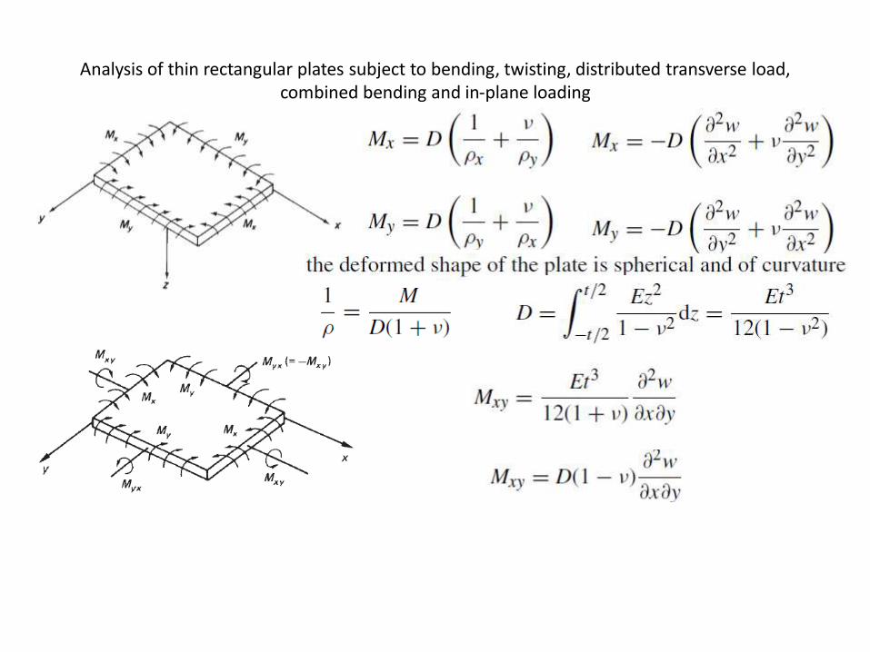
Analysis of thin rectangular plates subject to bending, twisting, distributed transverse load, combined bending and in-plane loading


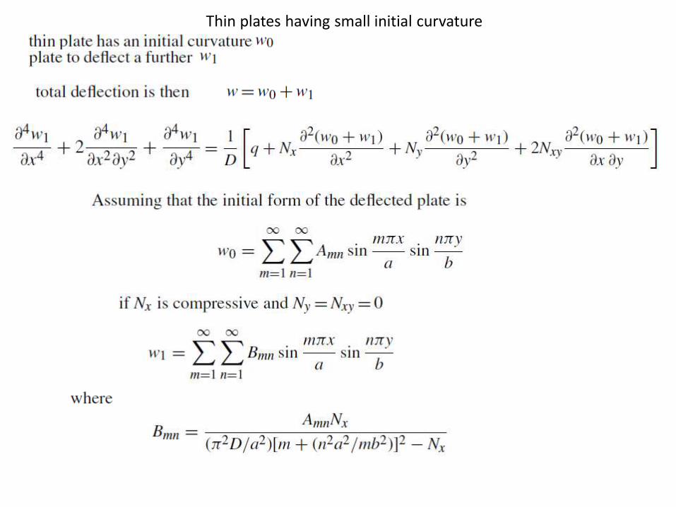
Thin plates having small initial curvature
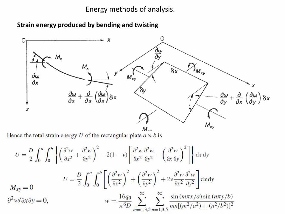
Energy methods of analysis.
Strain energy produced by bending and twisting
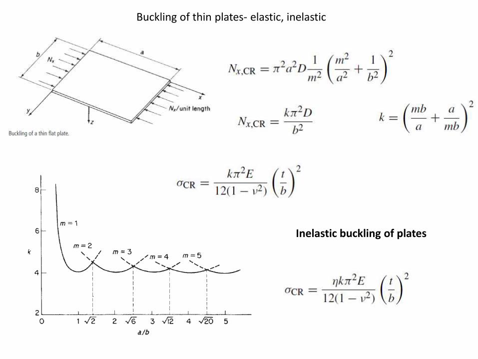
Buckling of thin plates- elastic, inelastic
Inelastic buckling of plates


experimental determination of critical load for a flat plate

local instability, instability of stiffened panels,
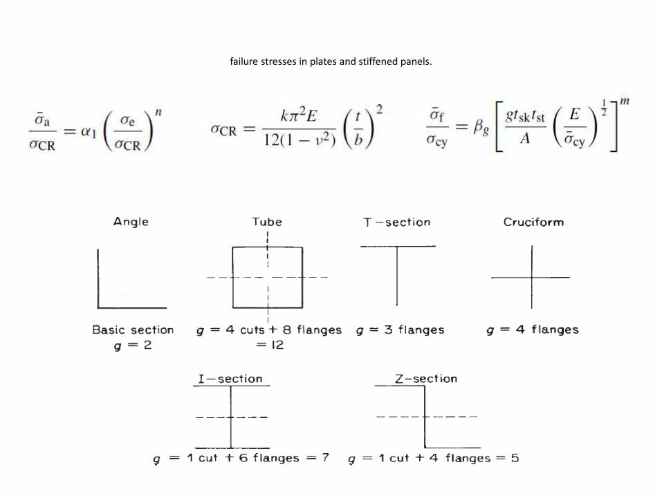
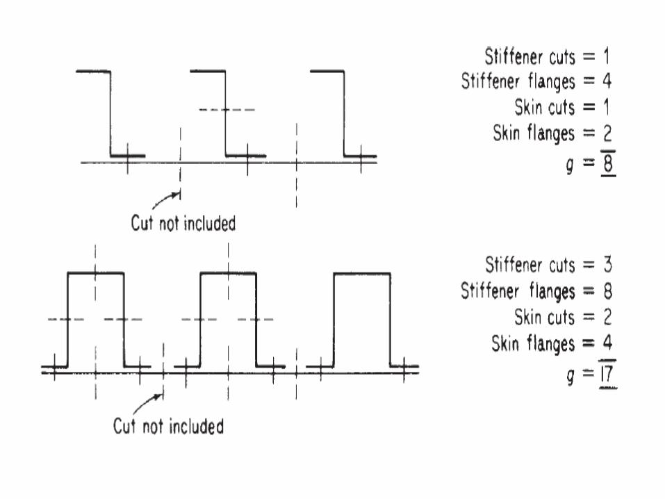
failure stresses in plates and stiffened panels.

Tension field beams- complete diagonal tension,
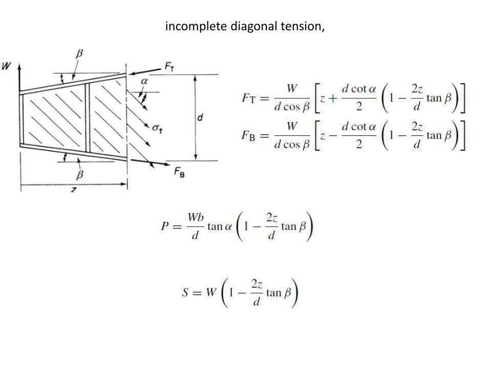
incomplete diagonal tension,
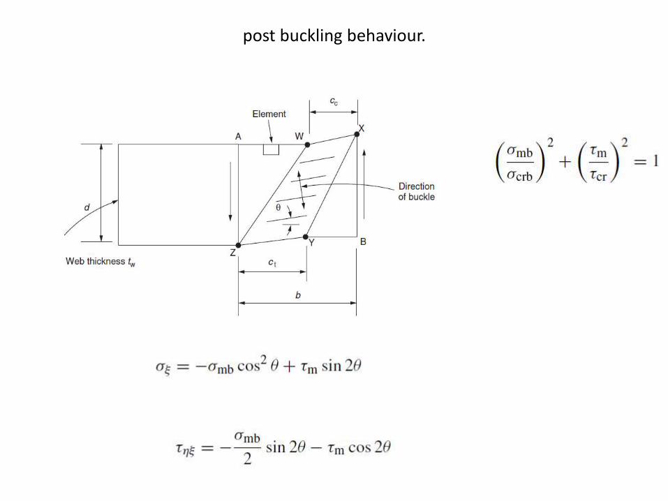
post buckling behaviour.

Unit-IIBending and Shear and Torsion Of
Thin Walled Beams:
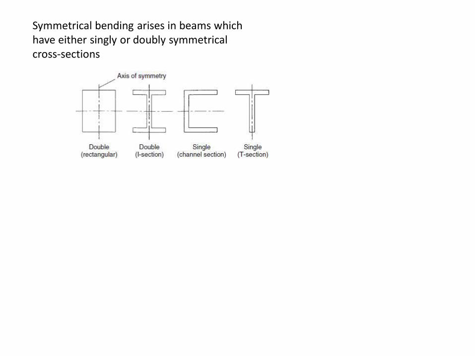
Symmetrical bending arises in beams which have either singly or doubly symmetricalcross-sections
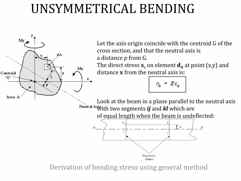
UNSYMMETRICAL BENDING
Derivation of bending stress using general method
Let the axis origin coincide with the centroid G of the cross section, and that the neutral axis isa distance p from G. The direct stress sz on element dA at point (x,y) and distance x from the neutral axis is:
Look at the beam in a plane parallel to the neutral axis with two segments ij and kl which areof equal length when the beam is undeflected:

Once the beam has been deflected this section will look like this
where: R = the radius of curvature dq = angle between planes ik and jl
The strain in plane kl can be defined as:
As the beam supports pure bending, the resultant loadon the end section must be zero. Hence
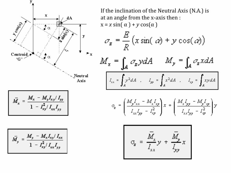
If the inclination of the Neutral Axis (N.A.) is at an angle from the x-axis then :x = x sin( α ) + y cos(α )

Neutral Axis:
• When a homogeneous beam is subjected to elastic bending, the neutral axis (NA) will pass through the centroid of its cross section, but the orientation of the NA depends on the orientation of the moment vector and the cross sectional shape of the beam.
• When the loading is unsymmetrical (at an angle) as seen in the figure below, the NA will also be at some angle - NOT necessarily the same angle as the bending moment.
• Realizing that at any point on the neutral axis, the bending strain and stress are zero, we can use the general bending stress equation to find its orientation. Setting the stress to zero and solving for the slope y/x gives
(

SHEAR FLOW AND SHEAR CENTRE
Restrictions: 1. Shear stress at every point in the beam must be less than the elastic limit of the
material in shear. 2. Normal stress at every point in the beam must be less than the elastic limit of the
material in tension and in compression. 3. Beam's cross section must contain at least one axis of symmetry.
4. The applied transverse (or lateral) force(s) at every point on the beam must pass through the elastic axis of the beam. Recall that elastic axis is a line connecting
cross-sectional shear centers of the beam. Since shear center always falls on the cross-sectional axis of symmetry, to assure the previous statement is satisfied, at
every point the transverse force is applied along the cross-sectional axis of symmetry.
5. The length of the beam must be much longer than its cross sectional dimensions. 6. The beam's cross section must be uniform along its length.

Shear Center
If the line of action of the force passes through the Shear Center of the beam section, then the beam will only bend without any twist. Otherwise, twist will accompany bending.
The shear center is in fact the centroid of the internal shear force system. Depending on the beam's cross-sectional shape along its length, the location of shear center may vary from section to section. A line connecting all the shear centers is called the elastic axis of the beam. When a beam is under the action of a more general lateral load system, then to prevent the beam from twisting, the load must be centered along the elastic axis of the beam.

Shear Center
• The two following points facilitate the determination of the shear center location.
1. The shear center always falls on a cross-sectional axis of symmetry. 2. If the cross section contains two axes of symmetry, then the shear center is
located at their intersection. Notice that this is the only case where shear center and centroid coincide.

SHEAR STRESS DISTRIBUTION
RECTANGLE T-SECTION

SHEAR FLOW DISTRIBUTION
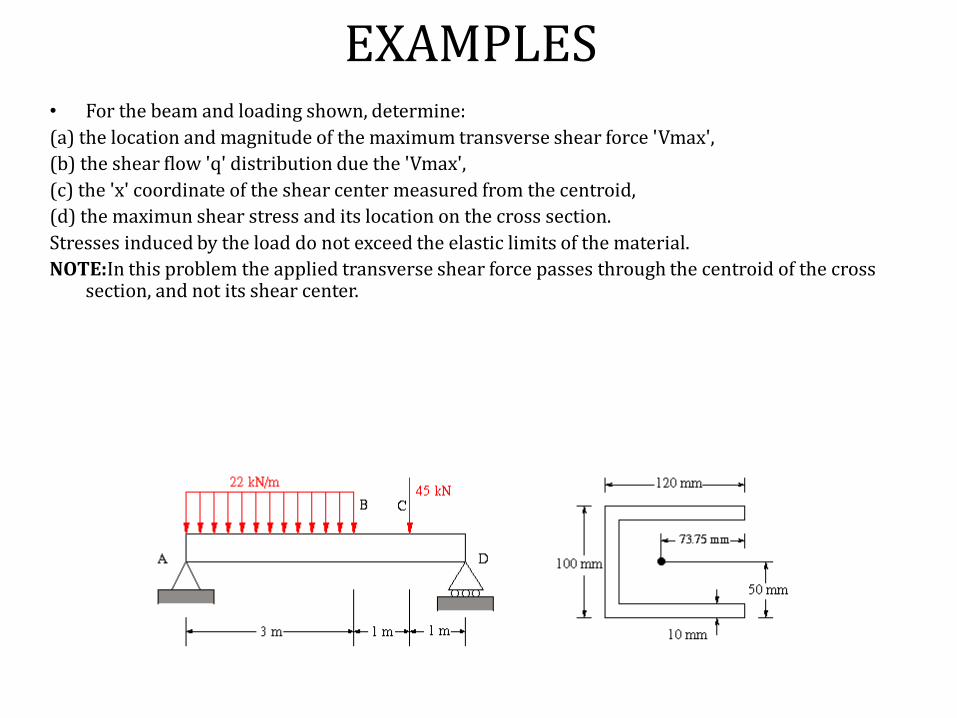
EXAMPLES• For the beam and loading shown, determine:
(a) the location and magnitude of the maximum transverse shear force 'Vmax',
(b) the shear flow 'q' distribution due the 'Vmax',
(c) the 'x' coordinate of the shear center measured from the centroid,
(d) the maximun shear stress and its location on the cross section.
Stresses induced by the load do not exceed the elastic limits of the material.
NOTE:In this problem the applied transverse shear force passes through the centroid of the cross section, and not its shear center.
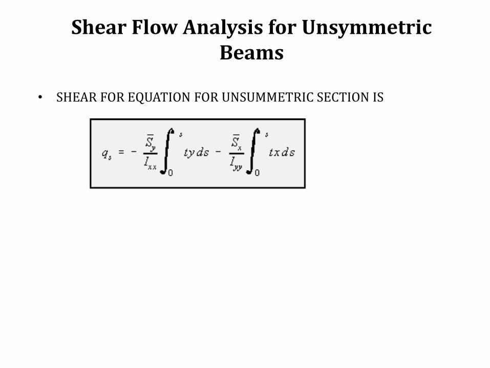
Shear Flow Analysis for UnsymmetricBeams
• SHEAR FOR EQUATION FOR UNSUMMETRIC SECTION IS

SHEAR FLOW DISTRIBUTION
• For the beam and loading shown, determine: • (a) the location and magnitude of the maximum
transverse shear force, • (b) the shear flow 'q' distribution due to 'Vmax', • (c) the 'x' coordinate of the shear center
measured from the centroid of the cross section. • Stresses induced by the load do not exceed the
elastic limits of the material. The transverse shear force is applied through the shear center at every section of the beam. Also, the length of each member is measured to the middle of the adjacent member.

Beams with Constant Shear Flow Webs
Assumptions:
1. Calculations of centroid, symmetry, moments of area and moments of inertia are based totally on the areas and distribution of beam stiffeners.
2. A web does not change the shear flow between two adjacent stiffeners and as such would be in the state of constant shear flow.
3. The stiffeners carry the entire bending-induced normal stresses, while the web(s) carry the entire shear flow and corresponding shear stresses.
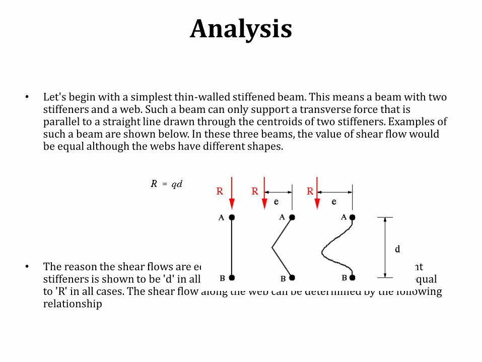
Analysis
• Let's begin with a simplest thin-walled stiffened beam. This means a beam with two stiffeners and a web. Such a beam can only support a transverse force that is parallel to a straight line drawn through the centroids of two stiffeners. Examples of such a beam are shown below. In these three beams, the value of shear flow would be equal although the webs have different shapes.
• The reason the shear flows are equal is that the distance between two adjacent stiffeners is shown to be 'd' in all cases, and the applied force is shown to be equal to 'R' in all cases. The shear flow along the web can be determined by the following relationship

Important Features of
Two-Stiffener, Single-Web Beams:
1. Shear flow between two adjacent stiffeners is constant. 2. The magnitude of the resultant shear force is only a function of the straight
line between the two adjacent stiffeners, and is absolutely independent of the web shape.
3. The direction of the resultant shear force is parallel to the straight line connecting the adjacent stiffeners.
4. The location of the resultant shear force is a function of the enclosed area (between the web, the stringers at each end and the arbitrary point 'O'), and the straight distance between the adjacent stiffeners. This is the only quantity that depends on the shape of the web connecting the stiffeners.
5. The line of action of the resultant force passes through the shear center of the section.

EXAMPLE
• For the multi-web, multi-stringer open-section beam shown, determine
(a) the shear flow distribution,
(b) the location of the shear center
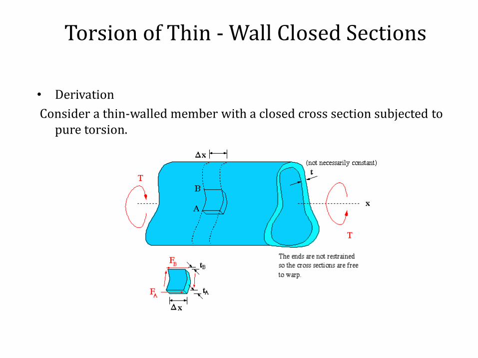
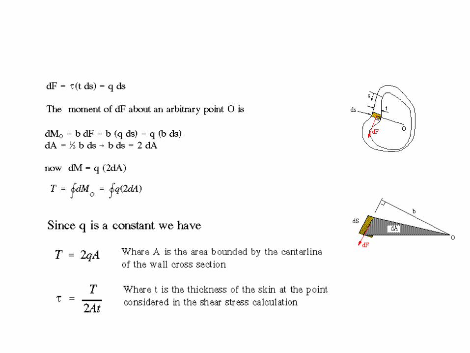
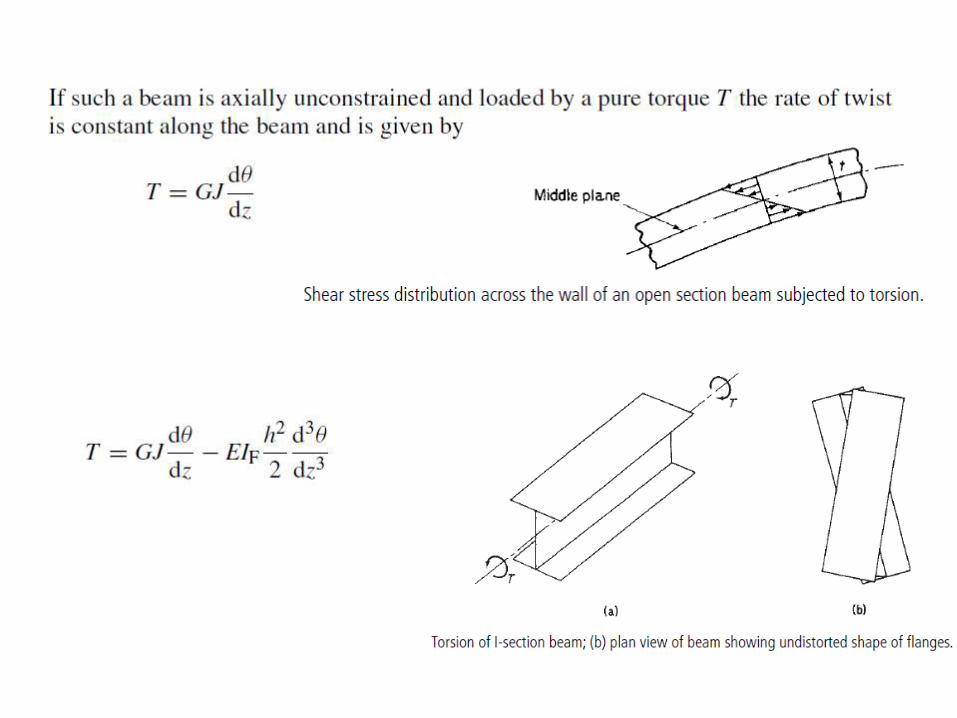
Torsion of Thin - Wall Closed Sections
• Derivation
Consider a thin-walled member with a closed cross section subjected to pure torsion.
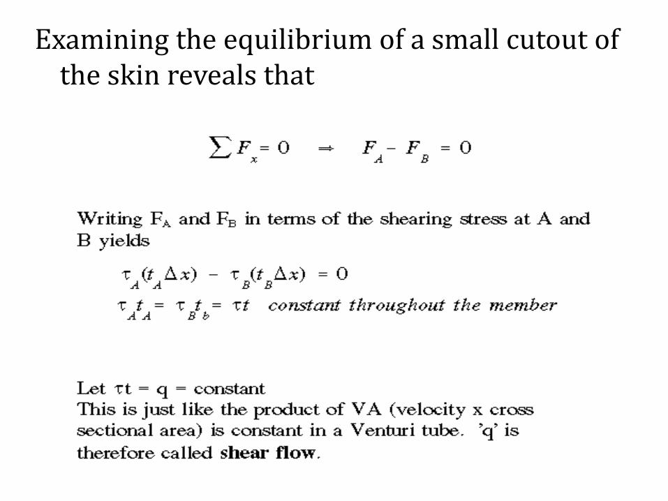
Examining the equilibrium of a small cutout of the skin reveals that

Angle of Twist
By applying strain energy equation due to shear and Castigliano'sTheorem the angle of twist for a thin-walled closed section can be shown to be
Since T = 2qA, we have
If the wall thickness is constant along each segment of the cross section, the integral can be replaced by a simple summation
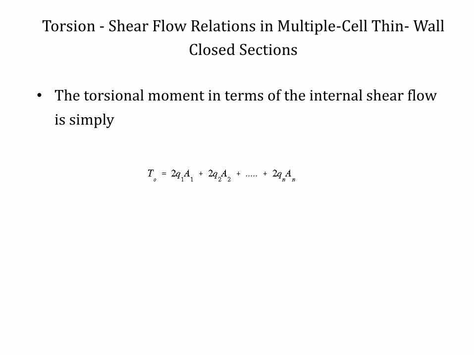
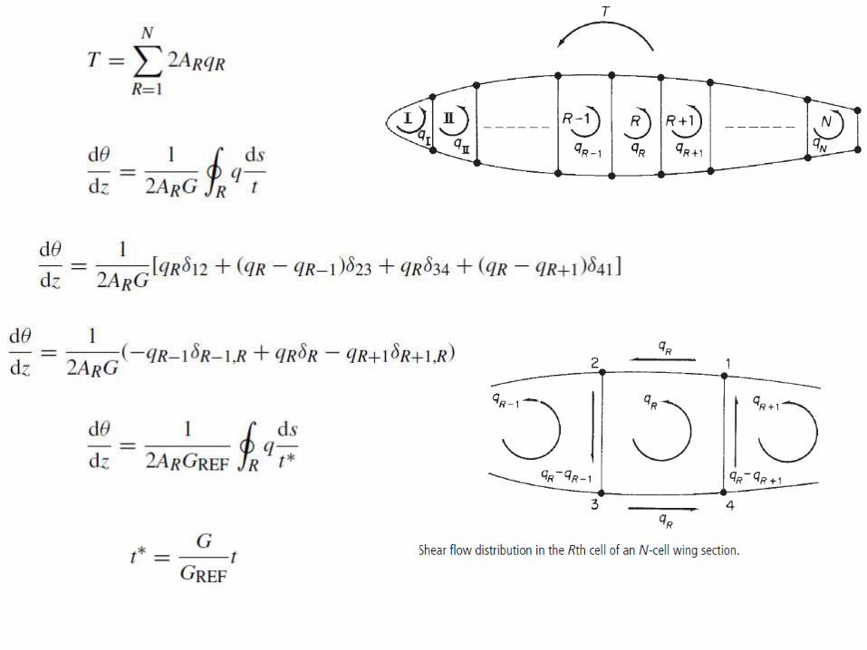
Torsion - Shear Flow Relations in Multiple-Cell Thin- Wall
Closed Sections
• The torsional moment in terms of the internal shear flow
is simply
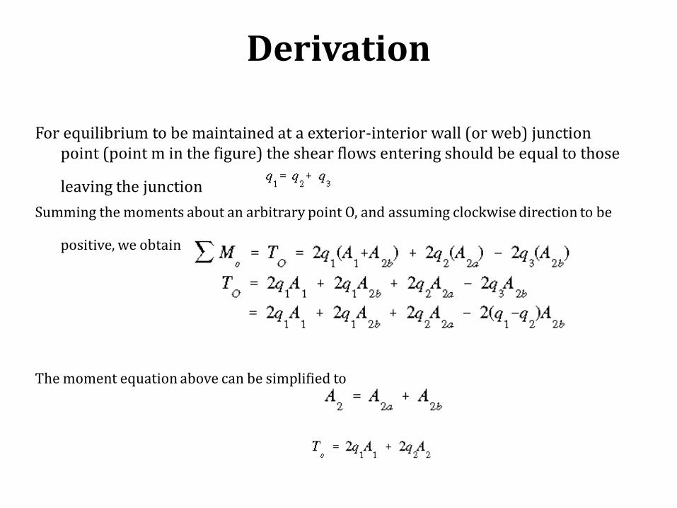
Derivation
For equilibrium to be maintained at a exterior-interior wall (or web) junction point (point m in the figure) the shear flows entering should be equal to those
leaving the junction
Summing the moments about an arbitrary point O, and assuming clockwise direction to be
positive, we obtain
The moment equation above can be simplified to

Shear Stress Distribution and Angle of Twist for Two-Cell
Thin-Walled Closed Sections
• The equation relating the shear flow along the exterior
wall of each cell to the resultant torque at the section is given as
This is a statically indeterminate problem. In order
to find the shear flows q1 and q2, the compatibility
relation between the angle of twist in cells 1 and 2 must be used. The compatibility requirement can be stated as
where
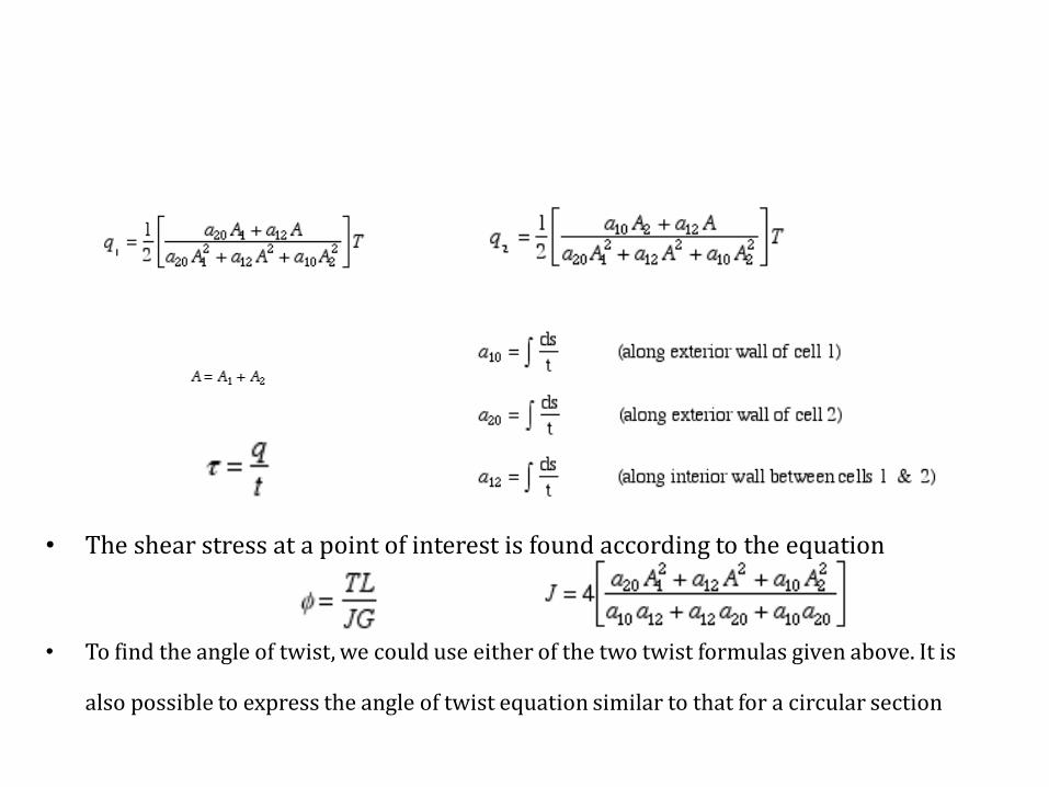
• The shear stress at a point of interest is found according to the equation
• To find the angle of twist, we could use either of the two twist formulas given above. It is
also possible to express the angle of twist equation similar to that for a circular section

Shear Stress Distribution and Angle of Twist for Multiple-Cell Thin-
Wall Closed Sections
• In the figure above the area outside of the cross section will be designated as cell (0). Thus to designate the exterior walls of cell (1), we use the notation 1-0. Similarly for cell (2) we use 2-0 and for cell (3) we use 3-0. The interior walls will be designated by the names of adjacent cells.
• the torque of this multi-cell member can be related to the shear flows in exterior walls as follows

For elastic continuity, the angles of twist in all cells must be equal
• The direction of twist chosen to be positive is clockwise.

TRANSVERSE SHEAR LOADING OF BEAMS WITH CLOSED CROSS SECTIONS
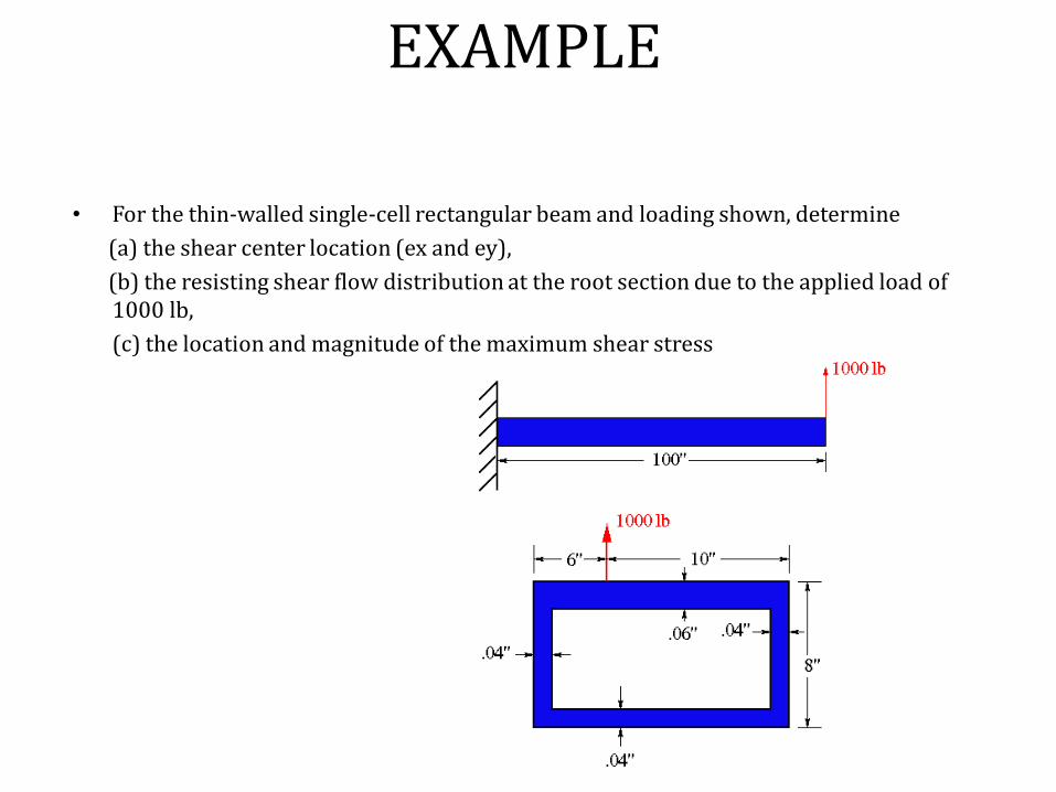
EXAMPLE
• For the thin-walled single-cell rectangular beam and loading shown, determine
(a) the shear center location (ex and ey),
(b) the resisting shear flow distribution at the root section due to the applied load of 1000 lb,
(c) the location and magnitude of the maximum shear stress

Unit-IIIStructural Idealisation of Thin Walled Beams
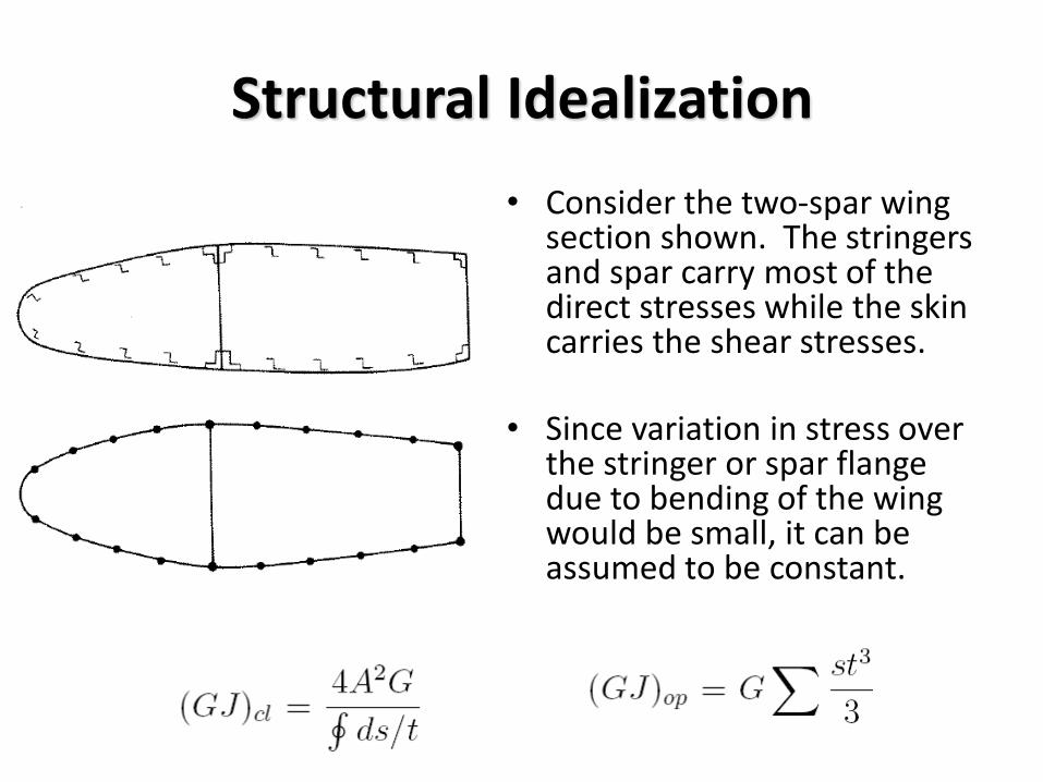
Structural Idealization
• Consider the two-spar wing section shown. The stringers and spar carry most of the direct stresses while the skin carries the shear stresses.
• Since variation in stress over the stringer or spar flange due to bending of the wing would be small, it can be assumed to be constant.

Structural Idealization
• Stingers and spar flanges can then be replaced by concentrations of areas known as booms.
• It can be assumed that all direct stresses are carried by booms and the skin carries only shear.
• Direct stress carrying capacity of the skin may be accounted for by increasing the boom cross-section area.

Structural Idealization
• If skin does carry direct stress, we idealize it as a section that carries only shear stress, and add effective area to the booms.
• M @ Right Side
• Similarly:
Effective boom area due to skin carrying direct stress –these add to the boom areas of flanges, strings, spars, etc..
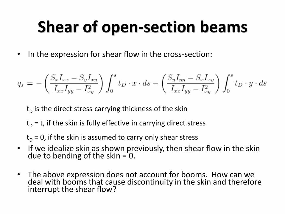
Shear of open-section beams
• In the expression for shear flow in the cross-section:
• If we idealize skin as shown previously, then shear flow in the skin due to bending of the skin = 0.
• The above expression does not account for booms. How can we deal with booms that cause discontinuity in the skin and therefore interrupt the shear flow?
tD is the direct stress carrying thickness of the skin
tD = t, if the skin is fully effective in carrying direct stress
tD = 0, if the skin is assumed to carry only shear stress

Shear of open-section beams
• Sx and Sy produce direct stresses due to bending in the booms (and skin) and shear stresses in the skin

Shear of open-section beams
• rth boom has a cross-sectional area Br
• Shear flows in skin adjacent to it are q1 and q2.
• Equilibrium in z direction of previous figure
• This gives:

Shear of open-section beams
• Recall:
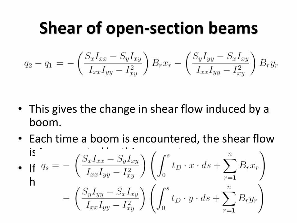
Shear of open-section beams
• This gives the change in shear flow induced by a boom.
• Each time a boom is encountered, the shear flow is incremented by this amount.
• If at some distance s at the profile, if n booms have been passed:

Open C/S Sample Problem
• Calculate the shear flow distribution in channel due to a 4.8 kN vertical shear load acting through the shear center.
• Booms carry all the direct stresses (Br
= 300 mm2)
n
r
rr
xx
y
s yBI
Sq
1

Open C/S Sample Problem
2622 mm 10482003004 AdIxx
n
r
rr
n
r
rrs yByBq11
4
6
3
101048
108.4
Calculate Ixx: (Only consider direct stress carrying areas) I.e. Booms
At the outside of boom 1, qs = 0. As boom 1 is crossed, the shear flow changes to:
N/mm 6200300100 4
12 q
q1

Open C/S Sample Problem
There will be no further changes in shear flow until the next boom (2) is crossed.
At the outside of boom 4, the shear flow is zero (qs = 0) as expected
N/mm 12200300106 4
23 q
q2
N/mm 62003001012 4
34 q
q3
N/mm 0200300106 4

Open C/S Sample Problem
6 N/mm
12 N/mm
6 N/mm
N/mm 6
N/mm 12
N/mm 6
34
23
12
q
q
q
How come all the signs are negative?
S1
S 2
S3
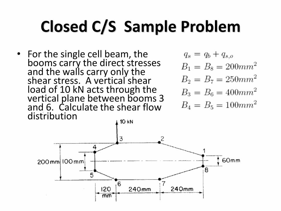
Closed C/S Sample Problem
• For the single cell beam, the booms carry the direct stresses and the walls carry only the shear stress. A vertical shear load of 10 kN acts through the vertical plane between booms 3 and 6. Calculate the shear flow distribution

Closed C/S Sample Problem
n
r
srr
xx
y
s qyBI
Sq
1
0,
Centroid on Horizontal Axis of Symmetry. Ixy = 0Also Sx = 0, tD = 0
2
4
2
3
2
2
2
1 50100100302 BBBBI xx
Ixx can be calculated from the direct stress carrying area of the booms
Substituting B1,…B4 gives Ixx = 13.86 x 106 mm4
n
r
srr
n
r
srrs qyBqyBq1
0,
4
1
0,6
3
1022.71086.13
1010

Closed C/S Sample Problem
N/mm 5.32501001022.79.28q
N/mm 9.281004001022.7
0
4
b,45
4
34,
23,
b
b
q
q
Introduce a cut in the wall 23 and calculate the basic shear flow around the walls
B3y3
Since the tD = 0
y4B4
symmetry)(by 0
symmetry)(by N/mm 9.28
23,67,
34,56,
bb
bb
N/mm 4.22302001022.71.18
N/mm 1.181002501022.7
4
18,
4
21,
b
b
q
qy2B2
B1 y1
symmetry)(by N/mm 1.1821,87, bb qq

Closed C/S Sample Problem
• Taking moments about the intersection of the line of action of shear load and horizontal axis:
0,20 sb Aqdspq
is broken up into segments where each qb is constant
Draw out the shear flow distribution to determine the sign of the moment generatedby the shear flow on each segment
Solve for qs,0
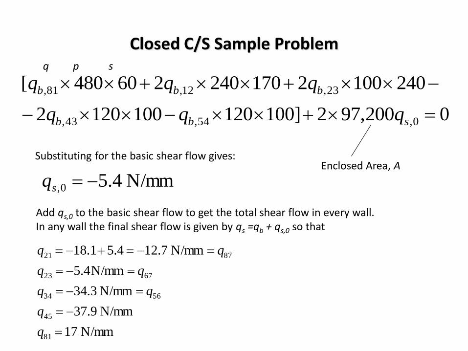
Closed C/S Sample Problem
0200,972]1001201001202
2401002170240260480[
0,54,43,
23,12,81,
sbb
bbb
qqq
qqqq p s
Substituting for the basic shear flow gives:
N/mm 4.50, sq
Add qs,0 to the basic shear flow to get the total shear flow in every wall.In any wall the final shear flow is given by qs =qb + qs,0 so that
N/mm 17
N/mm 9.37
N/mm 3.34
N/mm4.5
N/mm 7.124.51.18
81
45
5634
6723
8721
q
q
Enclosed Area, A

UNIT- IVStructural and Loading
Discontinuities in Thin Walled Beams

Closed section beams- shear stress distribution of a closed
section beam built in at one end under bending, shear and
torsion loads.
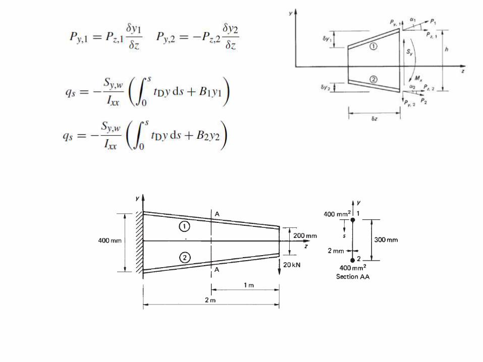
If the moment centre is chosen to coincide with the lines of action of Sx and Sy then

Open section beams

• Shear lag- effect of shearing strains in beams-
redistribution of bending stresses due to
restraining of warping, limitation of
elementary bending theory, effect of
accounting for shear lag on the estimated
strength.

UNIT- VStress Analysis of Aircraft Components- Wing, Fuselage:
.

Wing spars and box beams- tapered wing spar, open and closed section beams, beams having variable stringer areas. Wings-Three-boom shell in bending, torsion, shear, tapered wings, deflections, cut-outs in wings.Bending, shear, torsion, cut-outs in fuselages. Fuselage frames and wing ribs- principles of stiffener/ web construction, fuselage frames, wing ribs