Embed Size (px)
Citation preview
UNIT II
COMPUTER NETWORKS : PHYSICAL LAYER
Guided transmission media - Wireless transmission - Communication satellites - The public
switched telephone network.
Physical layer
- Transport a raw bit stream from one machine to another.
- Defines the mechanical, electrical, and timing interfaces to the network.
Various physical media can be used for the actual transmission. They are roughly grouped into
1. Guided media -Twisted, copper wire and fiber optics
2. Unguided media - radio and lasers through the air.
Magnetic Media
Write data onto magnetic tape or removable media (e.g., recordable DVDs), and physically
transport. It is often more cost effective
Used in applications in which high bandwidth or cost per bit transported is the key factor. As
an example, consider the following case.
Assume an Ultrium tape of 200 gigabytes and a box of 60 x 60 x 60 cm which can store 1000 of
these tapes. So the total capacity of box is 200 terabytes or 1600 terabits. Assume the box of
tapes can be delivered anywhere in the United States in 24 hours.
So, bandwidth is 1600 terabits/86,400 sec, or 19 Gbps.
1600000/86,400=19 Gbps
If the destination is only an hour distance, the bandwidth is
1600000/3600=444 Gbps.
No computer network can even approach this. Cost of tape is $40 only and can be reused 10
times. So it is cheap also.
• Bandwidth characteristics of magnetic tape are excellent, the delay characteristics are poor.
• Transmission time is measured in minutes or hours, not milliseconds. For many applications
an on-line connection is needed.
• This is one of the factors which lead to the usage of cables.
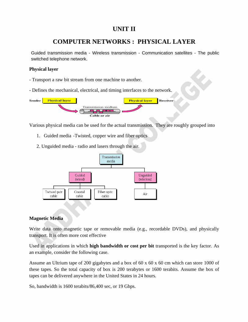
Twisted-Pair Cable
A twisted pair consists of two insulated copper wires, typically about 1 mm thick. The wires
are twisted together in a helical form, just like a DNA molecule. The most common application
of the twisted pair is the telephone system.
Reason for Twisting
1. Twisting is done because two parallel wires constitute a fine antenna. When the wires are
twisted, the waves from different twists cancel out, so the wire radiates less effectively.
2. When many twisted pairs are bundled together and encased in a protective sheath, the pairs in
these bundles would interfere with one another.
Properties
1. Twisted pairs can run several kilometers without amplification, but for longer distances,
repeaters are needed.
2. Twisted pairs can be used for transmitting either analog or digital signals.
3. The bandwidth depends on the thickness of the wire and the distance traveled, but several
megabits/sec can be achieved for a few kilometers in many cases.
4. Adequate performance and low cost.
Twisted pair cabling comes in several varieties, two of which are important for computer
networks. They are,
1. Category-3 (16 MHZ)
2. Category-5 (100 MHZ)
Category-3 twisted pairs consist of two insulated wires gently twisted together.
Category-5 are similar to category-3 pairs, but with more twists per centimeter, which results in
less crosstalk and a better-quality signal over longer distances, making them more suitable for
high-speed computer communication.
Up-and-coming categories are 6 and 7, which are capable of handling signals with bandwidths of
250 MHz and 600 MHz, respectively.
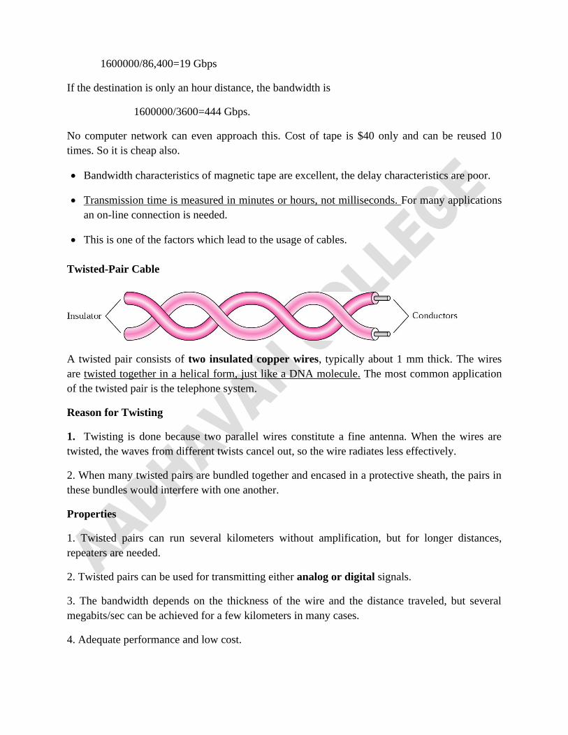
All of these wiring types are often referred to as UTP (Unshielded Twisted Pair).
There is also bulky, expensive, shielded twisted pair cables are also available.
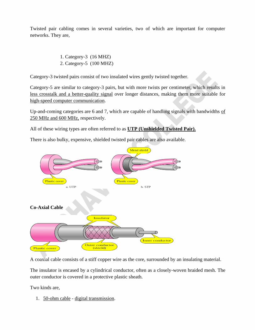
Co-Axial Cable
A coaxial cable consists of a stiff copper wire as the core, surrounded by an insulating material.
The insulator is encased by a cylindrical conductor, often as a closely-woven braided mesh. The
outer conductor is covered in a protective plastic sheath.
Two kinds are,
1. 50-ohm cable - digital transmission.
2. 75-ohm cable - analog transmission, cable television and Internet over cable.
Properties
1. It has better shielding than twisted pairs, so it can span longer distances at higher speeds.
2. The construction and shielding give it a good combination of high bandwidth and excellent
noise immunity.
3. The bandwidth possible depends on the cable quality, length, and signal-to-noise ratio of the
data signal.
Modern cables have a bandwidth of close to 1 GHz. Coax is still widely used for cable television
and metropolitan area networks.
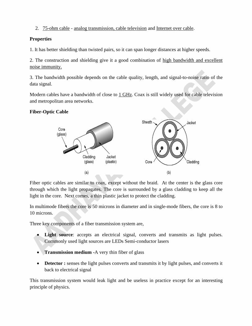
Fiber-Optic Cable
Fiber optic cables are similar to coax, except without the braid. At the center is the glass core
through which the light propagates. The core is surrounded by a glass cladding to keep all the
light in the core. Next comes, a thin plastic jacket to protect the cladding.
In multimode fibers the core is 50 microns in diameter and in single-mode fibers, the core is 8 to
10 microns.
Three key components of a fiber transmission system are,
• Light source: accepts an electrical signal, converts and transmits as light pulses.
Commonly used light sources are LEDs Semi-conductor lasers
• Transmission medium -A very thin fiber of glass
• Detector : senses the light pulses converts and transmits it by light pulses, and converts it
back to electrical signal
This transmission system would leak light and be useless in practice except for an interesting
principle of physics.
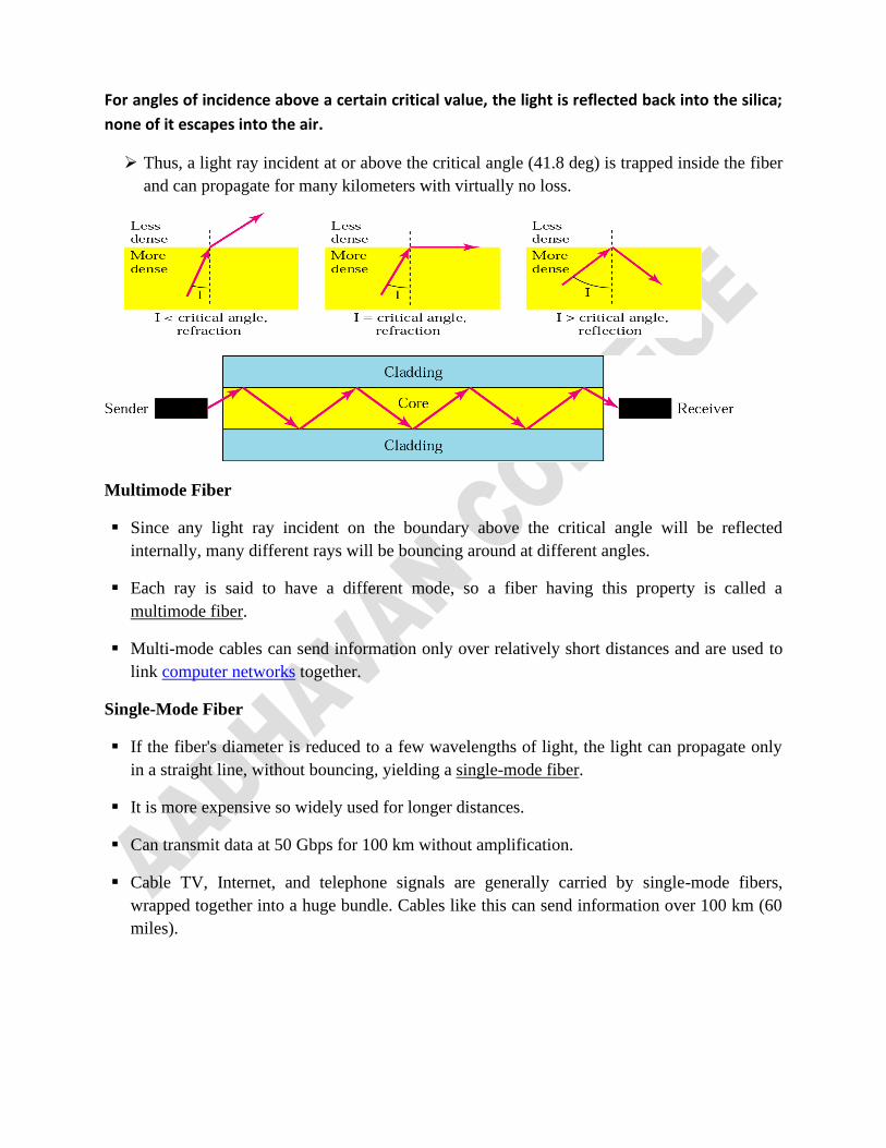
For angles of incidence above a certain critical value, the light is reflected back into the silica;
none of it escapes into the air.
➢ Thus, a light ray incident at or above the critical angle (41.8 deg) is trapped inside the fiber
and can propagate for many kilometers with virtually no loss.
Multimode Fiber
▪ Since any light ray incident on the boundary above the critical angle will be reflected
internally, many different rays will be bouncing around at different angles.
▪ Each ray is said to have a different mode, so a fiber having this property is called a
multimode fiber.
▪ Multi-mode cables can send information only over relatively short distances and are used to
link computer networks together.
Single-Mode Fiber
▪ If the fiber's diameter is reduced to a few wavelengths of light, the light can propagate only
in a straight line, without bouncing, yielding a single-mode fiber.
▪ It is more expensive so widely used for longer distances.
▪ Can transmit data at 50 Gbps for 100 km without amplification.
▪ Cable TV, Internet, and telephone signals are generally carried by single-mode fibers,
wrapped together into a huge bundle. Cables like this can send information over 100 km (60
miles).
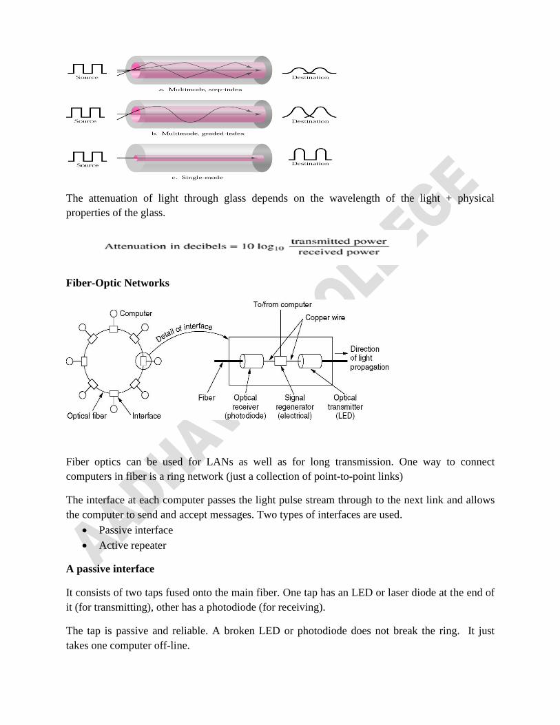
The attenuation of light through glass depends on the wavelength of the light + physical
properties of the glass.
Fiber-Optic Networks
Fiber optics can be used for LANs as well as for long transmission. One way to connect
computers in fiber is a ring network (just a collection of point-to-point links)
The interface at each computer passes the light pulse stream through to the next link and allows
the computer to send and accept messages. Two types of interfaces are used.
• Passive interface
• Active repeater
A passive interface
It consists of two taps fused onto the main fiber. One tap has an LED or laser diode at the end of
it (for transmitting), other has a photodiode (for receiving).
The tap is passive and reliable. A broken LED or photodiode does not break the ring. It just
takes one computer off-line.
The passive interfaces lose light at each junction. So number of computers and total ring length
are greatly restricted.
Active repeater
▪ The incoming light is converted to an electrical signal, regenerated to full strength if it has
been weakened, and retransmitted as light.
▪ Since signal is regenerated at each interface, the individual computer-to-computer links can
be kilometers long.
▪ If an active repeater fails, the ring is broken and the network goes down.
▪ Purely optical repeaters are now being used, too.
Properties of Fiber
▪ Higher bandwidths.
▪ low attenuation (repeaters are needed only about every 50 km on long lines)
▪ Not being affected by power surges (pitch), electromagnetic interference, or power failures,
Corrosive (acidic) chemicals in the air, making it ideal for harsh factory environments.
▪ It is thin and lightweight.
▪ Do not leak light and are quite difficult to tap.
▪ Excellent security against potential wire-tappers.
Problems
▪ Can be damaged easily by being bent too much.
▪ Since optical transmission is inherently unidirectional, two-way communication requires
either two fibers or two frequency bands on one fiber.
▪ Interfaces cost more than electrical interfaces.
▪ High installation cost
WIRELESS TRANSMISSION
▪ For users those who want to access networks on the go, twisted pair, coax, and fiber optics
are of no use. Wireless communication is the answer to them.
Principle of wireless transmission
▪ When electrons move, they create electromagnetic waves that travel thru space.
▪ When an antenna of appropriate size is attached to an electrical circuit, the
electromagnetic waves can be broadcast efficiently and received by a receiver some
distance away.
Frequency
▪ The number of oscillations per second of a wave is called its frequency, f, and is measured
in Hz
Wavelength
▪ The distance between two consecutive maxima (or minima) is called the wavelength.
Denoted by the Greek letter l (lambda).
In vacuum, all electromagnetic waves travel at the same speed, usually called the speed of
light, c, is approximately 3 x 10⁸ m/sec. In copper or fiber the speed slows to about 2/3 of this
value and becomes slightly frequency dependent.
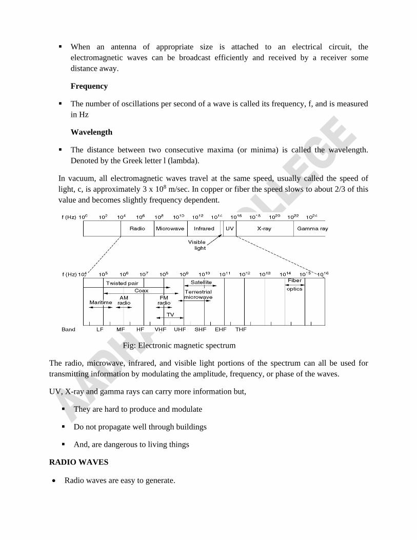
Fig: Electronic magnetic spectrum
The radio, microwave, infrared, and visible light portions of the spectrum can all be used for
transmitting information by modulating the amplitude, frequency, or phase of the waves.
UV, X-ray and gamma rays can carry more information but,
▪ They are hard to produce and modulate
▪ Do not propagate well through buildings
▪ And, are dangerous to living things
RADIO WAVES
• Radio waves are easy to generate.
• It can travel long distances and can penetrate buildings easily.
• Radio waves are Omni-directional, i.e. they travel in all directions
The properties of RW are frequency dependent
• At low frequency : pass through obstacles well
• At high frequency : they travel in straight lines , bounce off obstacles, and absorbed by
rain
Advantage
Transmitter and receiver do not have to be aligned
Disadvantage
• Interference of signals
• less secure
• Government license is required to use particular frequency band
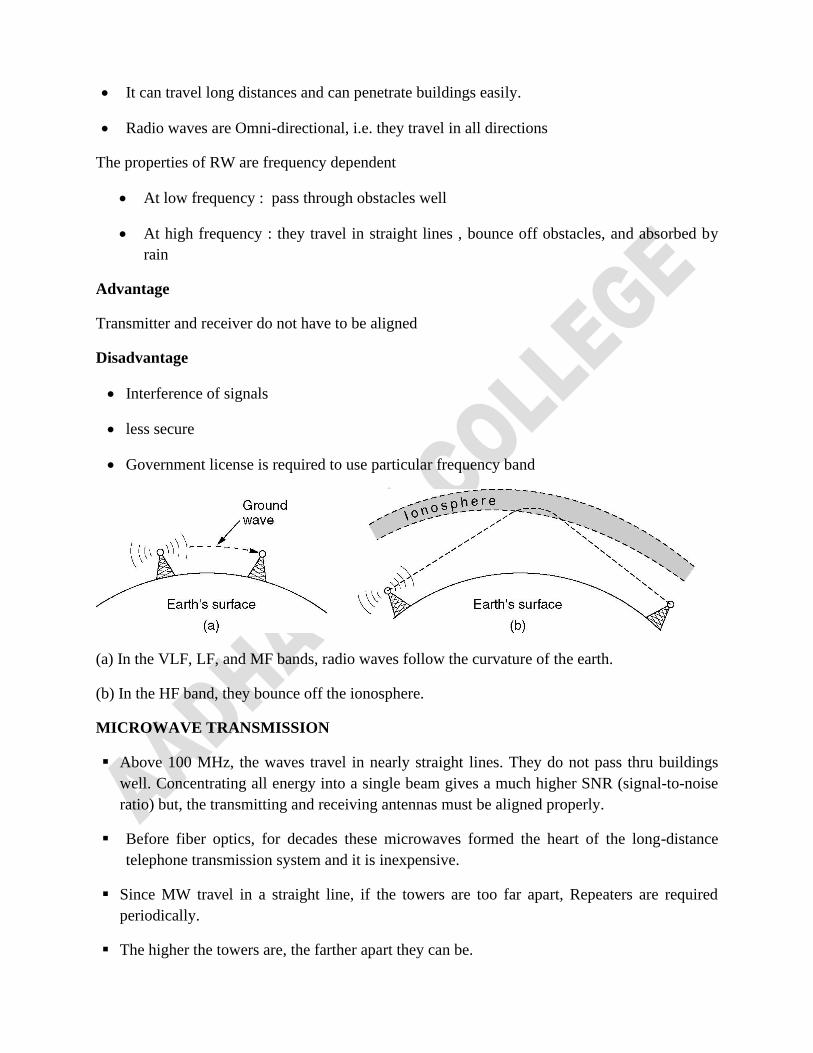
(a) In the VLF, LF, and MF bands, radio waves follow the curvature of the earth.
(b) In the HF band, they bounce off the ionosphere.
MICROWAVE TRANSMISSION
▪ Above 100 MHz, the waves travel in nearly straight lines. They do not pass thru buildings
well. Concentrating all energy into a single beam gives a much higher SNR (signal-to-noise
ratio) but, the transmitting and receiving antennas must be aligned properly.
▪ Before fiber optics, for decades these microwaves formed the heart of the long-distance
telephone transmission system and it is inexpensive.
▪ Since MW travel in a straight line, if the towers are too far apart, Repeaters are required
periodically.
▪ The higher the towers are, the farther apart they can be.
▪ Even though MW travel in a straight line. There is some divergence in the space.
Some waves may be refracted off low-lying atmospheric layers and may take slightly longer
to arrive than the direct waves. The delayed waves may arrive out of phase with the direct
wave and thus cancel the signal. This effect is called multi-path fading.
▪ It is a serious problem and is weather and frequency dependent.
Applications of Microwave
Microwave communication is so widely used for long-distance telephone communication,
mobile phones, television distribution, and other uses that a severe shortage of spectrum has
developed.
INFRARED OR MILLIMETER WAVES
▪ Short range wave used in TV remotes, VCRs, etc
▪ They are relatively directional, cheap, and easy to build
▪ Directional
▪ Do not pass through solid objects
Advantage
▪ No signal interference
▪ Secure
▪ No government license is required
Applications of Infrared
▪ Remote control Home- appliances
▪ Wireless Local Loop
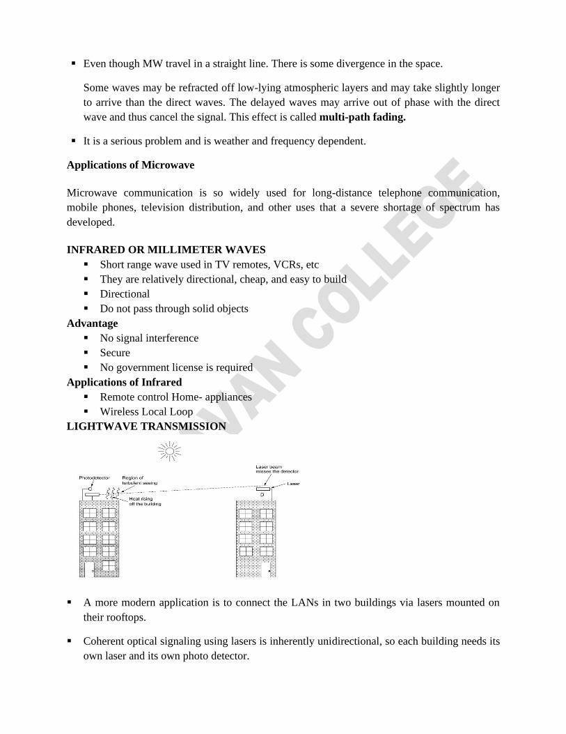
LIGHTWAVE TRANSMISSION
▪ A more modern application is to connect the LANs in two buildings via lasers mounted on
their rooftops.
▪ Coherent optical signaling using lasers is inherently unidirectional, so each building needs its
own laser and its own photo detector.
Advantage
▪ Offers very high bandwidth
▪ Very low cost.
▪ It is also relatively easy to install
▪ Does not require an FCC license.
Disadvantage
▪ Laser beams cannot penetrate rain or thick fog
▪ Convection currents can interfere with laser communication systems.
COMMUNICATION SATELLITES
Reasons to prefer satellite for communication
1. Wide area coverage of the earth’s surface.
2. Transmission delay is about 0.3 sec.
3. Transmission cost is independent of distance
Note: There are about 750 satellites in the space; most of them are used for communication.
Communication satellites
1. A communication satellite is a big microwave repeater in the sky.
2. It contains several transponders,
▪ listens to some portion of the spectrum,
▪ amplifies the incoming signal,
▪ rebroadcasts it at another frequency
Another frequency (in rebroadcast) is to avoid interference with the incoming signal. This mode
of operation is known as a bent pipe.
The downward beams can be of broad, covering fraction of the earth's surface and narrow,
covering only hundreds of kilometers.
3. Orbital period
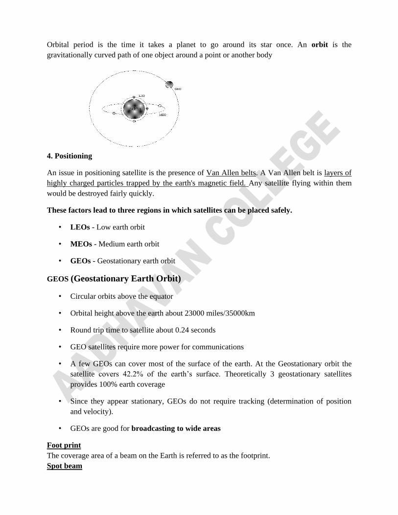
Orbital period is the time it takes a planet to go around its star once. An orbit is the
gravitationally curved path of one object around a point or another body
4. Positioning
An issue in positioning satellite is the presence of Van Allen belts. A Van Allen belt is layers of
highly charged particles trapped by the earth's magnetic field. Any satellite flying within them
would be destroyed fairly quickly.
These factors lead to three regions in which satellites can be placed safely.
• LEOs - Low earth orbit
• MEOs - Medium earth orbit
• GEOs - Geostationary earth orbit
GEOS (Geostationary Earth Orbit)
• Circular orbits above the equator
• Orbital height above the earth about 23000 miles/35000km
• Round trip time to satellite about 0.24 seconds
• GEO satellites require more power for communications
• A few GEOs can cover most of the surface of the earth. At the Geostationary orbit the
satellite covers 42.2% of the earth’s surface. Theoretically 3 geostationary satellites
provides 100% earth coverage
• Since they appear stationary, GEOs do not require tracking (determination of position
and velocity).
• GEOs are good for broadcasting to wide areas
Foot print
The coverage area of a beam on the Earth is referred to as the footprint.
Spot beam
A tightly focused satellite radio beam designed to cover an area more limited than that of the
entire satellite footprint.
Because satellites have a limited number of frequencies to use, the ability to re-use a frequency
for different geographical locations allows for more local channels to be carried, since the same
frequency can be used in several regions.
Station keeping
The effects of solar, lunar, and planetary gravity tend to move the satellites away from their
assigned orbit slots and orientations. This activity is called station keeping. (The Process of
keeping a satellite in geosynchronous orbit within assigned boundaries is known as station
keeping).
This effect is countered (opposed) by on-board rocket motors.
A new development in communication satellite is VSATs (Very Small Aperture Terminals) are
low-cost micro stations.
These tiny terminals have
▪ 1-meter or smaller antennas
▪ Can put out about 1 watt of power.
▪ The uplink is 19.2 kbps,
▪ The downlink is more often 512 kbps or more.
Direct broadcast satellite television uses it for one-way transmission.
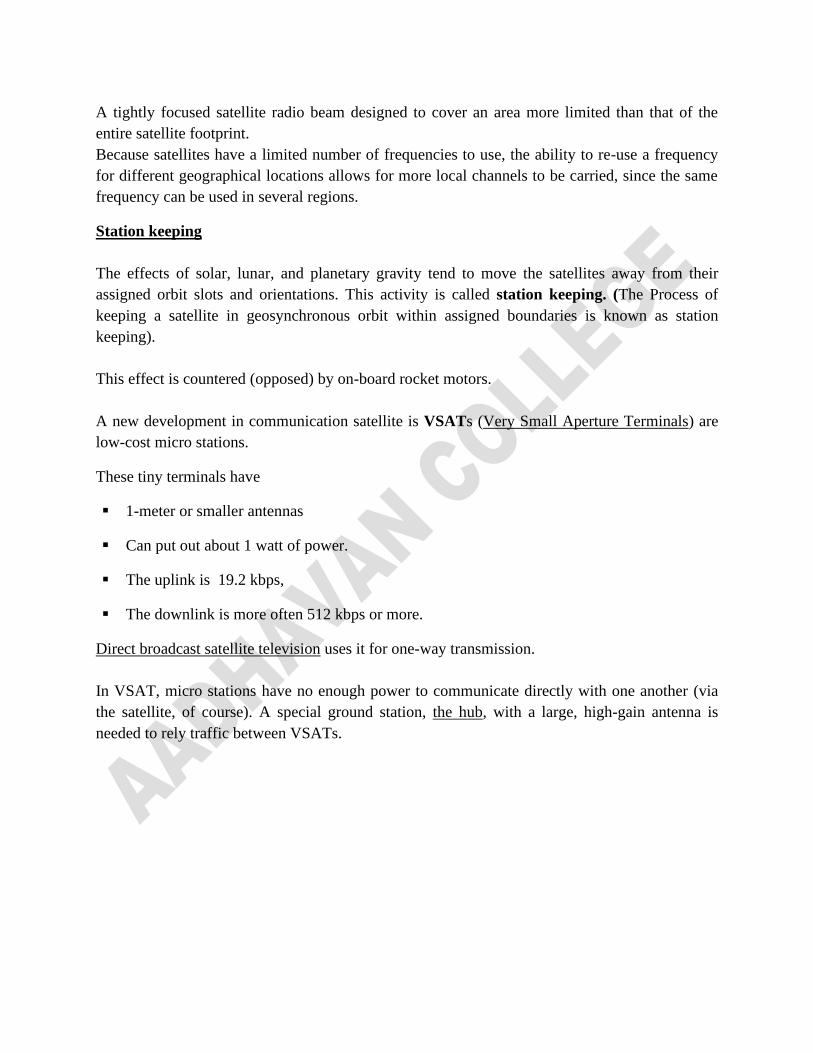
In VSAT, micro stations have no enough power to communicate directly with one another (via
the satellite, of course). A special ground station, the hub, with a large, high-gain antenna is
needed to rely traffic between VSATs.
Properties of communication satellites
1. Data travel in speed of light (nearly 300,000 km/sec)
2. Less propagation delay
- microwave links have a propagation delay of roughly 3 µsec/km,
- coaxial cable or fiber optic links have a delay of approximately 5 µsec/km.
Because, electromagnetic signals travel faster in air than in solid materials
3. Low cost
4. The cost of transmitting a message is independent of the distance traversed.
5. Excellent error rates
6. Deployed almost instantly,
Problems
1. Security and privacy - everybody can hear everything. So, Encryption is essential when
security is required.
2. Round-trip distance - the long round-trip distance introduces a substantial delay for GEO
satellites. It depends on the distance between the user and the ground station and the elevation
(height) of the satellite above the horizon
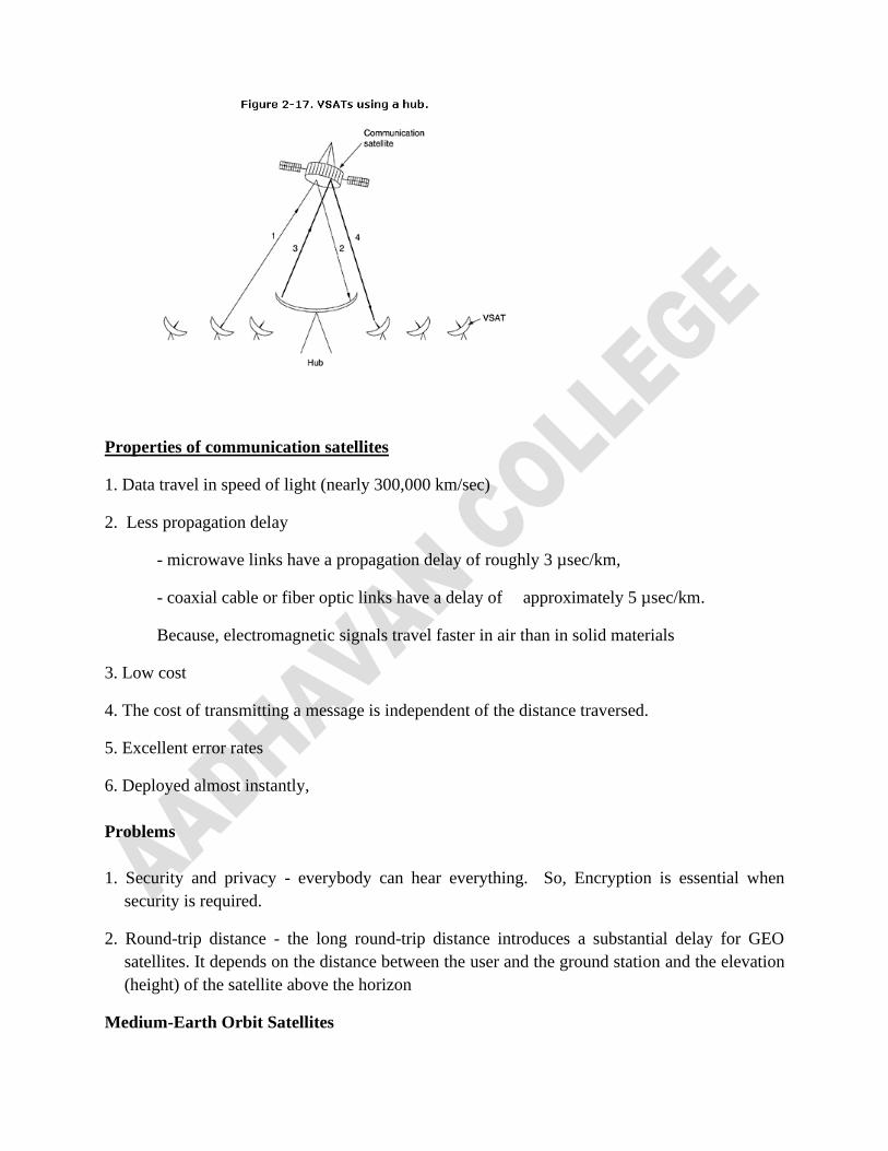
Medium-Earth Orbit Satellites
At much lower altitudes, between the two Van Allen belts, the MEO (Medium-Earth Orbit)
satellites are found.
-drift (flow) slowly in longitude,
- taking something like 6 hours to circle the earth.
- smaller footprint on the ground
- require less powerful transmitters to reach them.
Example of MEO:
The 24 GPS (Global Positioning System) satellites orbiting at about 18,000 km
Low-Earth Orbit Satellites
▪ Found at down in altitude satellites are so close to the earth,
▪ Due to rapid motion, large numbers of them are needed for a complete system,
▪ Ground stations do not need much power,
▪ The round-trip delay is only a few milliseconds.
Orbit and frequency allocation
Now-a-days, everyone like
1. Commercial telecommunication,
2. Television broadcasters,
3. governments,
4. military
Need a piece of the orbiting pie. To prevent confusion in the sky, orbit slot allocation is done by
ITU. Some countries maintain national property rights.
• Do not extend up to the moon
• No right to the orbit slots above its territory (region).
ITU frequency bands to satellite users.
To avoid contention for Frequencies (because the downlink transmissions interfere with existing
microwave users).
I) The C band
1. First designated for commercial satellite traffic.
2. Two frequency ranges are assigned in it.
- The lower one for downlink traffic (from the satellite)
- The upper one for uplink traffic (to the satellite).
3. Already overcrowded
II) The L and S bands - narrow and crowded.
III) Ku (K under) band - commercial telecommunication carriers
- Not (yet) congested,
- In these frequencies, satellites spaced as close as 1degree.
Problem of Ku
- Observed by rain. (Water is an excellent absorber of these short microwaves.)
Several widely separated ground stations, extra antennas, extra cables, and extra electronics to
enable rapid switching between stations will avoid the problem
IV) Ka (K above) band
- for commercial satellite traffic,
- Equipment is still expensive.
In addition to these commercial bands, many government and military bands also exist.
PUBLIC SWITCHED TELEPHONE SYSTEM
To connect two computers close to each other it is easy to run a cable between them. But for long
distances cables have to pass through a public road and it may result in high costs.
So, network designers must rely on the existing PSTN (Public Switched Telephone Network)
Structure of the Telephone System
Soon after Alexander Graham Bell patented the telephone in 1876, initial market was for the
sale of telephones, which came in pairs.
It was up to the customer to string a single wire between them.
It was resulted in fully-interconnected network.
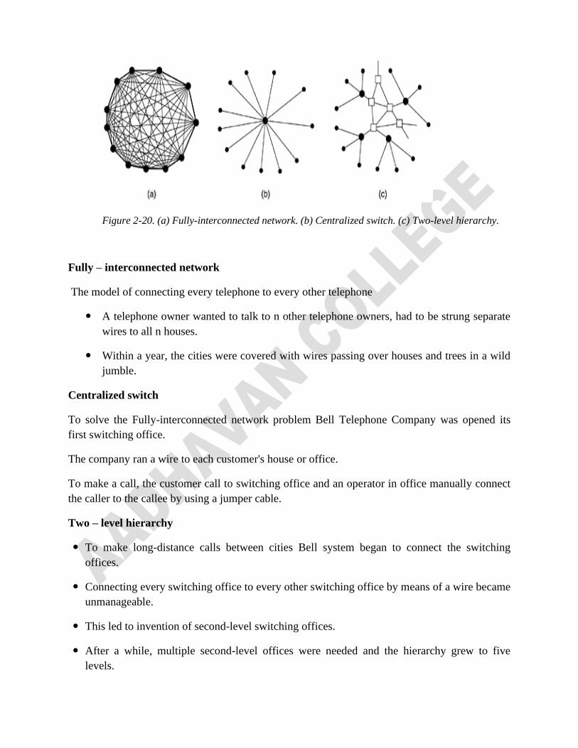
Figure 2-20. (a) Fully-interconnected network. (b) Centralized switch. (c) Two-level hierarchy.
Fully – interconnected network
The model of connecting every telephone to every other telephone
A telephone owner wanted to talk to n other telephone owners, had to be strung separate
wires to all n houses.
Within a year, the cities were covered with wires passing over houses and trees in a wild
jumble.
Centralized switch
To solve the Fully-interconnected network problem Bell Telephone Company was opened its
first switching office.
The company ran a wire to each customer's house or office.
To make a call, the customer call to switching office and an operator in office manually connect
the caller to the callee by using a jumper cable.
Two – level hierarchy
To make long-distance calls between cities Bell system began to connect the switching
offices.
Connecting every switching office to every other switching office by means of a wire became
unmanageable.
This led to invention of second-level switching offices.
After a while, multiple second-level offices were needed and the hierarchy grew to five
levels.
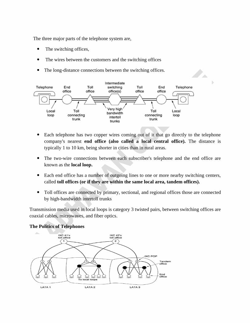
The three major parts of the telephone system are,
The switching offices,
The wires between the customers and the switching offices
The long-distance connections between the switching offices.
Each telephone has two copper wires coming out of it that go directly to the telephone
company's nearest end office (also called a local central office). The distance is
typically 1 to 10 km, being shorter in cities than in rural areas.
The two-wire connections between each subscriber's telephone and the end office are
known as the local loop.
Each end office has a number of outgoing lines to one or more nearby switching centers,
called toll offices (or if they are within the same local area, tandem offices).
Toll offices are connected by primary, sectional, and regional offices those are connected
by high-bandwidth intertoll trunks
Transmission media used in local loops is category 3 twisted pairs, between switching offices are
coaxial cables, microwaves, and fiber optics.
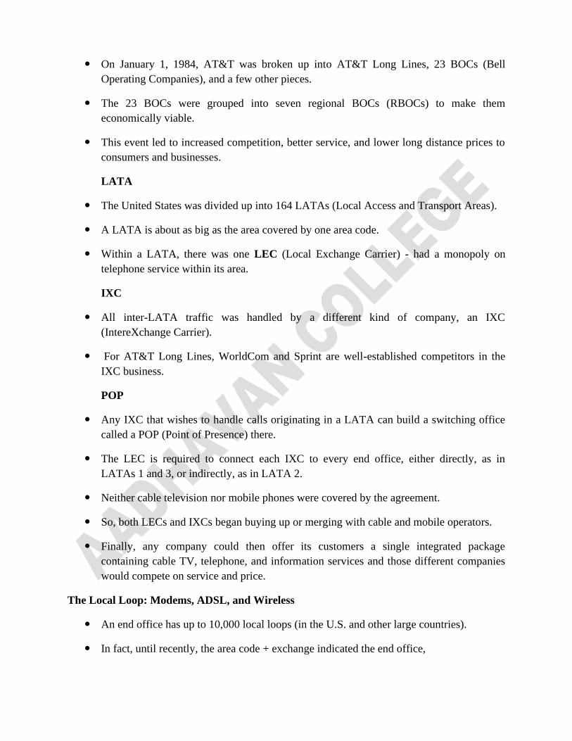
The Politics of Telephones
On January 1, 1984, AT&T was broken up into AT&T Long Lines, 23 BOCs (Bell
Operating Companies), and a few other pieces.
The 23 BOCs were grouped into seven regional BOCs (RBOCs) to make them
economically viable.
This event led to increased competition, better service, and lower long distance prices to
consumers and businesses.
LATA
The United States was divided up into 164 LATAs (Local Access and Transport Areas).
A LATA is about as big as the area covered by one area code.
Within a LATA, there was one LEC (Local Exchange Carrier) - had a monopoly on
telephone service within its area.
IXC
All inter-LATA traffic was handled by a different kind of company, an IXC
(IntereXchange Carrier).
For AT&T Long Lines, WorldCom and Sprint are well-established competitors in the
IXC business.
POP
Any IXC that wishes to handle calls originating in a LATA can build a switching office
called a POP (Point of Presence) there.
The LEC is required to connect each IXC to every end office, either directly, as in
LATAs 1 and 3, or indirectly, as in LATA 2.
Neither cable television nor mobile phones were covered by the agreement.
So, both LECs and IXCs began buying up or merging with cable and mobile operators.
Finally, any company could then offer its customers a single integrated package
containing cable TV, telephone, and information services and those different companies
would compete on service and price.
The Local Loop: Modems, ADSL, and Wireless
An end office has up to 10,000 local loops (in the U.S. and other large countries).
In fact, until recently, the area code + exchange indicated the end office,
so (212) 601-xxxx was a specific end office with 10,000 subscribers, numbered 0000
through 9999.
With the advent of competition for local service, this system was no longer tenable
because multiple companies wanted to own the end office code.
Also, the number of codes was basically used up, so complex mapping schemes had to be
introduced.
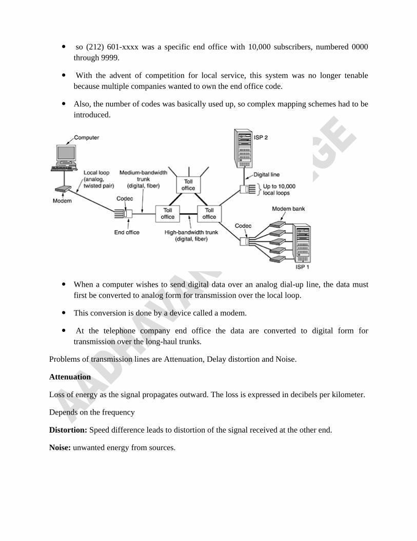
When a computer wishes to send digital data over an analog dial-up line, the data must
first be converted to analog form for transmission over the local loop.
This conversion is done by a device called a modem.
At the telephone company end office the data are converted to digital form for
transmission over the long-haul trunks.
Problems of transmission lines are Attenuation, Delay distortion and Noise.
Attenuation
Loss of energy as the signal propagates outward. The loss is expressed in decibels per kilometer.
Depends on the frequency
Distortion: Speed difference leads to distortion of the signal received at the other end.
Noise: unwanted energy from sources.