Embed Size (px)
Citation preview
CS601 Wireless Communication and Networks Unit - II
MTech CSE (PT, 2011-14) SRM, Ramapuram 1 hcr:innovationcse@gg
UNIT – II MAC, TELE COMMUNICATION AND
SATELLITE SYSTEMS Medium access Control Techniques- SDMA-TDMA-FDMA- CDMA- Comparison.
Tele communication systems- GSM-DECT and TETRA.
Satellite Systems- Routing, Localization and hand over.
MOTIVATION FOR A SPECIALIZED MAC
Problems in wireless networks
signal strength decreases proportional to the square of the distance
the sender would apply CS and CD, but the collisions happen at the receiver
it might be the case that a sender cannot “hear” the collision, i.e., CD does not work
furthermore, CS might not work if, e.g., a terminal is “hidden”
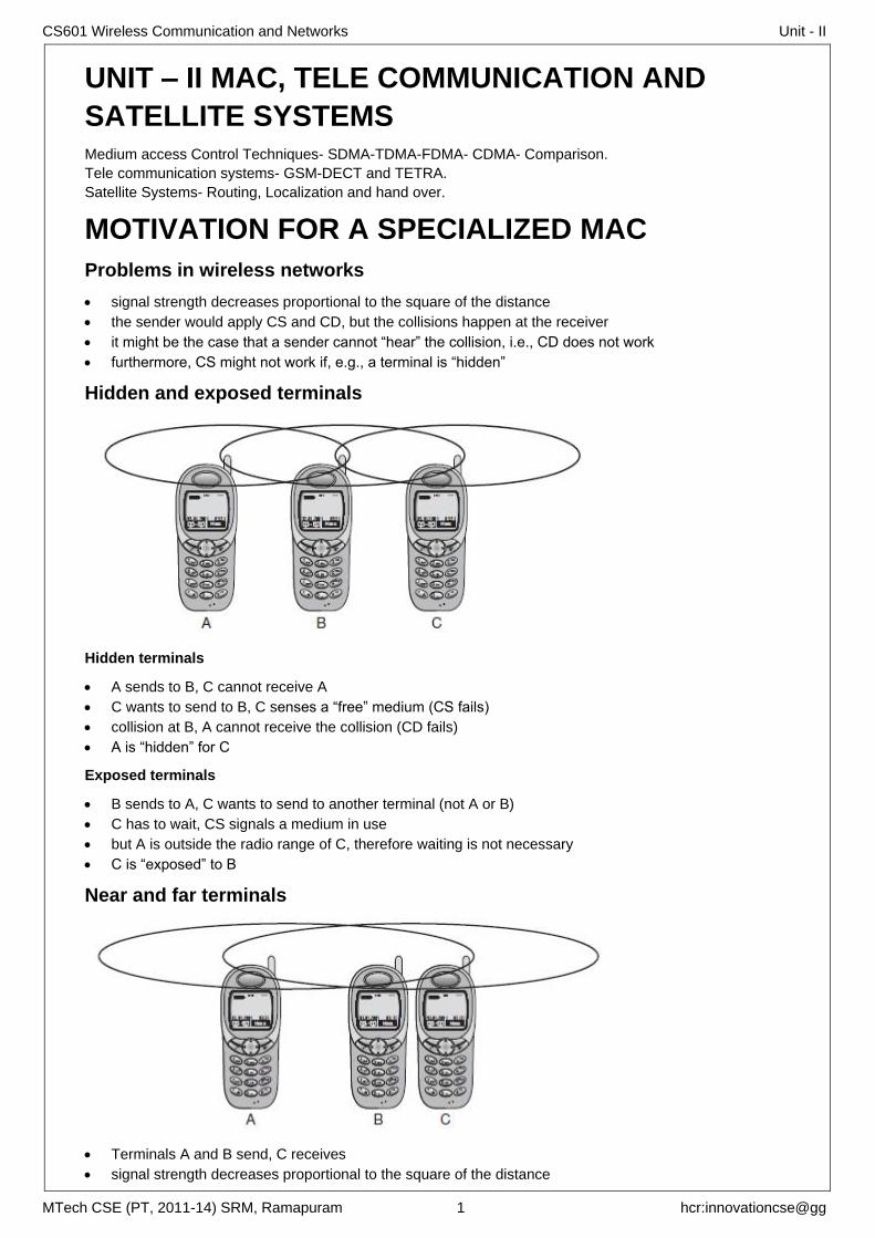
Hidden and exposed terminals
Hidden terminals
A sends to B, C cannot receive A
C wants to send to B, C senses a “free” medium (CS fails)
collision at B, A cannot receive the collision (CD fails)
A is “hidden” for C
Exposed terminals
B sends to A, C wants to send to another terminal (not A or B)
C has to wait, CS signals a medium in use
but A is outside the radio range of C, therefore waiting is not necessary
C is “exposed” to B
Near and far terminals
Terminals A and B send, C receives
signal strength decreases proportional to the square of the distance
CS601 Wireless Communication and Networks Unit - II
MTech CSE (PT, 2011-14) SRM, Ramapuram 2 hcr:innovationcse@gg
the signal of terminal B therefore drowns out A’s signal
C cannot receive A
If C for example was an arbiter for sending rights, terminal B would drown out terminal A already on the
physical layer
Also severe problem for CDMA-networks - precise power control needed!
Access methods SDMA/FDMA/TDMA
SDMA (Space Division Multiple Access)
o segment space into sectors, use directed antennas
o cell structure
FDMA (Frequency Division Multiple Access)
o assign a certain frequency to a transmission channel between a sender and a receiver
o permanent (e.g., radio broadcast), slow hopping (e.g., GSM), fast hopping (FHSS, Frequency Hopping
Spread Spectrum)
TDMA (Time Division Multiple Access)
o assign the fixed sending frequency to a transmission channel between a sender and a receiver for a
certain amount of time
Space Division Multiple Access (SDMA)
SDMA is used for allocating a separated space to users in wireless networks.
A typical application involves assigning an optimal base station to a mobile phone user.
The mobile phone may receive several base stations with different quality.
A MAC algorithm could now decide which base station is best, taking into account which frequencies
(FDM), time slots (TDM) or code (CDM) are still available (depending on the technology).
SDMA is never used in isolation but always in combination with one or more other schemes.
The basis for the SDMA algorithm is formed by cells and sectorized antennas which constitute the
infrastructure implementing space division multiplexing (SDM)
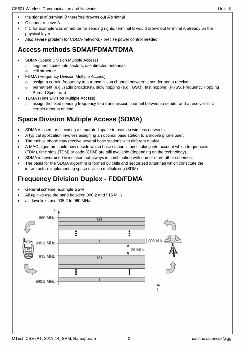
Frequency Division Duplex - FDD/FDMA
General scheme, example GSM
All uplinks use the band between 890.2 and 915 MHz,
all downlinks use 935.2 to 960 MHz.
CS601 Wireless Communication and Networks Unit - II
MTech CSE (PT, 2011-14) SRM, Ramapuram 3 hcr:innovationcse@gg
TIME DIVISION MULTIPLE ACCESS (TDMA) offers a much more flexible scheme, which comprises all technologies that allocate certain time slots for
communication, i.e., controlling TDM.
Tuning in to a certain frequency is not necessary, i.e., the receiver can stay at the same frequency the
whole time.
Using only one frequency, and thus very simple receivers and transmitters
Fixed TDM
The simplest algorithm for using TDM is allocating time slots for channels in a fixed pattern.
This results in a fixed bandwidth and is the typical solution for wireless phone systems
Assigning different slots for uplink and downlink using the same frequency - time division duplex (TDD).
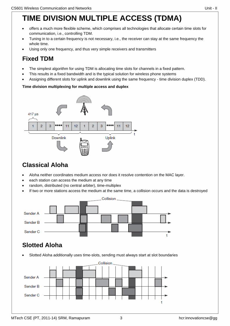
Time division multiplexing for multiple access and duplex
Classical Aloha
Aloha neither coordinates medium access nor does it resolve contention on the MAC layer.
each station can access the medium at any time
random, distributed (no central arbiter), time-multiplex
If two or more stations access the medium at the same time, a collision occurs and the data is destroyed
Slotted Aloha
Slotted Aloha additionally uses time-slots, sending must always start at slot boundaries
CS601 Wireless Communication and Networks Unit - II
MTech CSE (PT, 2011-14) SRM, Ramapuram 4 hcr:innovationcse@gg
Carrier Sense Multiple Access (CSMA)
sensing the carrier before accessing the medium
this decreases the probability of a collision.
o hidden terminals cannot be detected,
o if a hidden terminal transmits at the same time as another, a collision might occur at the receiver.
Types of CSMA
non-persistent CSMA
o stations sense the carrier and start sending immediately if the medium is idle.
o If the medium is busy, the station pauses a random amount of time before sensing the medium again
and repeating this pattern.
In p-persistent CSMA
o systems nodes also sense the medium, but only transmit with a probability of p, with the station
deferring to the next slot with the probability 1-p, i.e., access is slotted in addition.
In 1-persistent CSMA systems,
o all stations wishing to transmit access the medium at the same time, as soon as it becomes idle. This
will cause many collisions if many stations wish to send and block each other.
Demand Assigned Multiple Access (DAMA)
Also called Reservation Aloha.
Channel efficiency only 18% for Aloha, 36% for Slotted Aloha (assuming Poisson distribution for packet
arrival and packet length)
Reservation can increase efficiency to 80% a sender reserves a future time-slot
o sending within this reserved time-slot is possible without collision
o reservation also causes higher delays
o typical scheme for satellite links
Examples for reservation algorithms:
o Explicit Reservation according to Roberts (Reservation-ALOHA)
o Implicit Reservation (PRMA)
o Reservation-TDMA
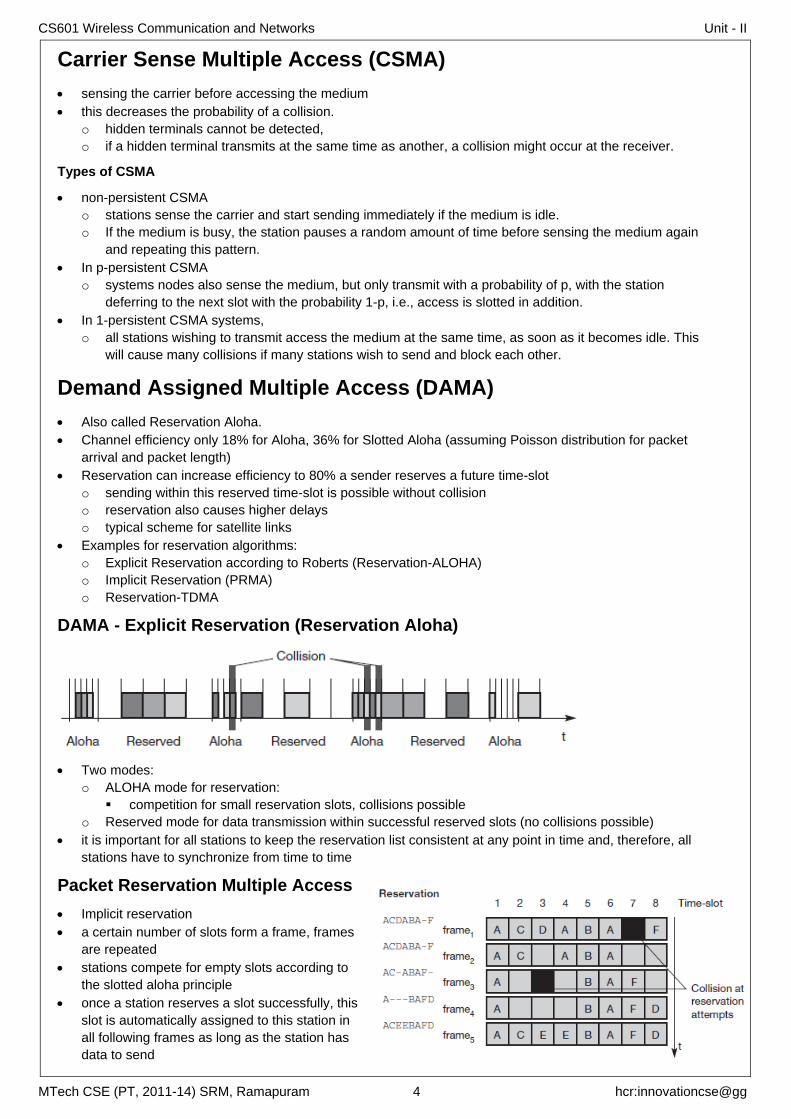
DAMA - Explicit Reservation (Reservation Aloha)
Two modes:
o ALOHA mode for reservation:
competition for small reservation slots, collisions possible
o Reserved mode for data transmission within successful reserved slots (no collisions possible)
it is important for all stations to keep the reservation list consistent at any point in time and, therefore, all
stations have to synchronize from time to time
Packet Reservation Multiple Access
Implicit reservation
a certain number of slots form a frame, frames
are repeated
stations compete for empty slots according to
the slotted aloha principle
once a station reserves a slot successfully, this
slot is automatically assigned to this station in
all following frames as long as the station has
data to send
CS601 Wireless Communication and Networks Unit - II
MTech CSE (PT, 2011-14) SRM, Ramapuram 5 hcr:innovationcse@gg
competition for this slots starts again as soon as the slot was empty in the last frame
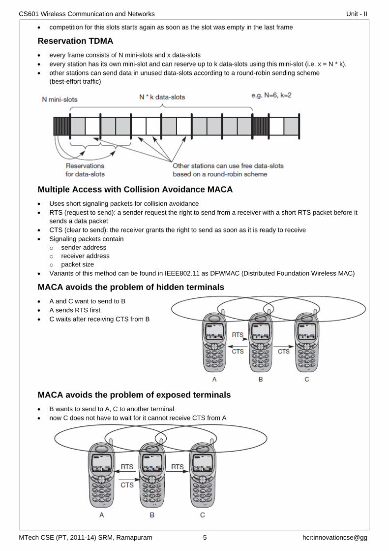
Reservation TDMA
every frame consists of N mini-slots and x data-slots
every station has its own mini-slot and can reserve up to k data-slots using this mini-slot (i.e. x = N * k).
other stations can send data in unused data-slots according to a round-robin sending scheme
(best-effort traffic)
Multiple Access with Collision Avoidance MACA
Uses short signaling packets for collision avoidance
RTS (request to send): a sender request the right to send from a receiver with a short RTS packet before it
sends a data packet
CTS (clear to send): the receiver grants the right to send as soon as it is ready to receive
Signaling packets contain
o sender address
o receiver address
o packet size
Variants of this method can be found in IEEE802.11 as DFWMAC (Distributed Foundation Wireless MAC)
MACA avoids the problem of hidden terminals
A and C want to send to B
A sends RTS first
C waits after receiving CTS from B
MACA avoids the problem of exposed terminals
B wants to send to A, C to another terminal
now C does not have to wait for it cannot receive CTS from A
CS601 Wireless Communication and Networks Unit - II
MTech CSE (PT, 2011-14) SRM, Ramapuram 6 hcr:innovationcse@gg
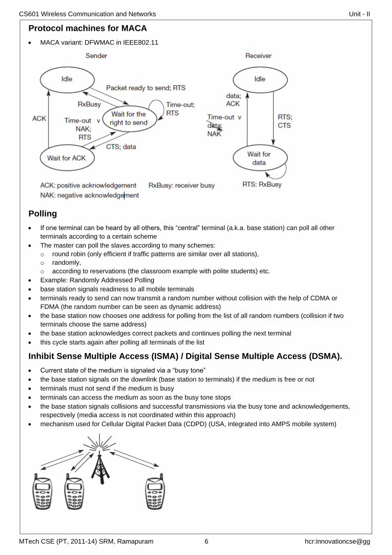
Protocol machines for MACA
MACA variant: DFWMAC in IEEE802.11
Polling
If one terminal can be heard by all others, this “central” terminal (a.k.a. base station) can poll all other
terminals according to a certain scheme
The master can poll the slaves according to many schemes:
o round robin (only efficient if traffic patterns are similar over all stations),
o randomly,
o according to reservations (the classroom example with polite students) etc.
Example: Randomly Addressed Polling
base station signals readiness to all mobile terminals
terminals ready to send can now transmit a random number without collision with the help of CDMA or
FDMA (the random number can be seen as dynamic address)
the base station now chooses one address for polling from the list of all random numbers (collision if two
terminals choose the same address)
the base station acknowledges correct packets and continues polling the next terminal
this cycle starts again after polling all terminals of the list
Inhibit Sense Multiple Access (ISMA) / Digital Sense Multiple Access (DSMA).
Current state of the medium is signaled via a “busy tone”
the base station signals on the downlink (base station to terminals) if the medium is free or not
terminals must not send if the medium is busy
terminals can access the medium as soon as the busy tone stops
the base station signals collisions and successful transmissions via the busy tone and acknowledgements,
respectively (media access is not coordinated within this approach)
mechanism used for Cellular Digital Packet Data (CDPD) (USA, integrated into AMPS mobile system)
CS601 Wireless Communication and Networks Unit - II
MTech CSE (PT, 2011-14) SRM, Ramapuram 7 hcr:innovationcse@gg
Code Division Multiple Access (CDMA)
all terminals send on the same frequency probably at the same time and can use the whole bandwidth of
the transmission channel
each sender has a unique random number, the sender XORs the signal with this random number
the receiver can “tune” into this signal if it knows the pseudo random number, tuning is done via a
correlation function
Advantages:
o all terminals can use the same frequency, no planning needed
o huge code space (e.g. 232
) compared to frequency space
o interferences (e.g. white noise) is not coded
o forward error correction and encryption can be easily integrated
Disadvantages:
o higher complexity of a receiver (receiver cannot just listen into the medium and start receiving if there is
a signal)
o all signals should have the same strength at a receiver
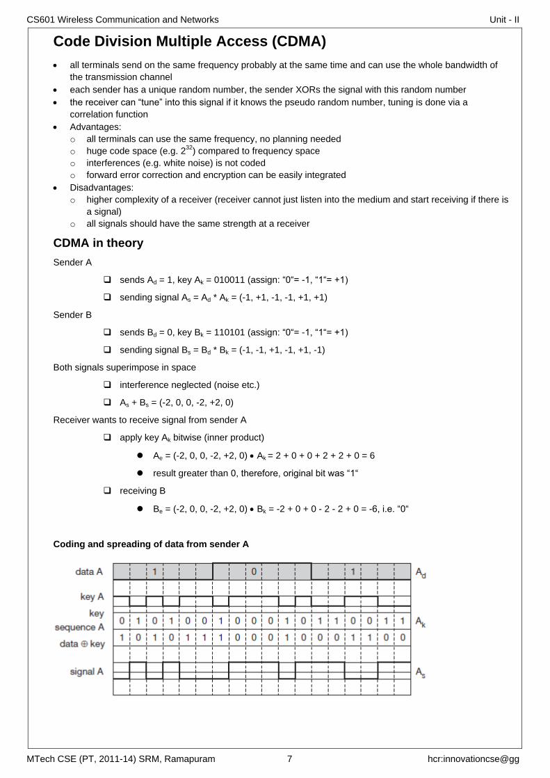
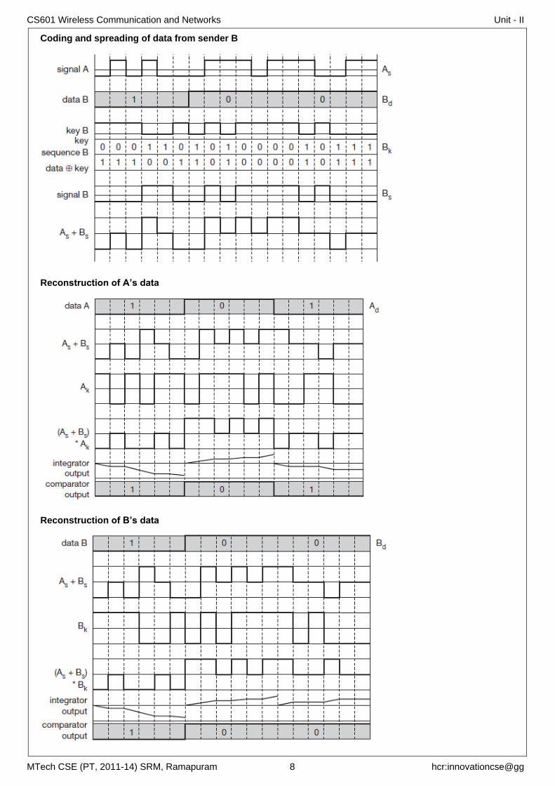
CDMA in theory
Sender A
sends Ad = 1, key Ak = 010011 (assign: “0“= -1, “1“= +1)
sending signal As = Ad * Ak = (-1, +1, -1, -1, +1, +1)
Sender B
sends Bd = 0, key Bk = 110101 (assign: “0“= -1, “1“= +1)
sending signal Bs = Bd * Bk = (-1, -1, +1, -1, +1, -1)
Both signals superimpose in space
interference neglected (noise etc.)
As + Bs = (-2, 0, 0, -2, +2, 0)
Receiver wants to receive signal from sender A
apply key Ak bitwise (inner product)
Ae = (-2, 0, 0, -2, +2, 0) Ak = 2 + 0 + 0 + 2 + 2 + 0 = 6
result greater than 0, therefore, original bit was “1“
receiving B
Be = (-2, 0, 0, -2, +2, 0) Bk = -2 + 0 + 0 - 2 - 2 + 0 = -6, i.e. “0“
Coding and spreading of data from sender A
CS601 Wireless Communication and Networks Unit - II
MTech CSE (PT, 2011-14) SRM, Ramapuram 8 hcr:innovationcse@gg
Coding and spreading of data from sender B
Reconstruction of A’s data
Reconstruction of B’s data
CS601 Wireless Communication and Networks Unit - II
MTech CSE (PT, 2011-14) SRM, Ramapuram 9 hcr:innovationcse@gg
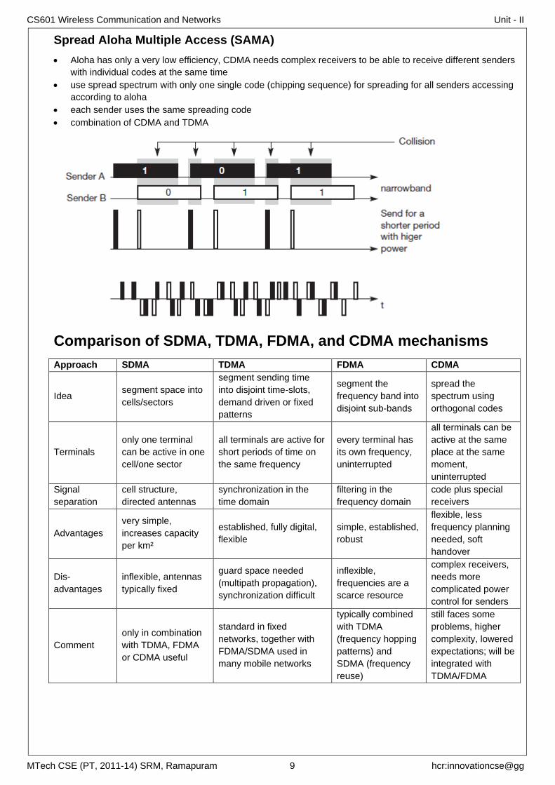
Spread Aloha Multiple Access (SAMA)
Aloha has only a very low efficiency, CDMA needs complex receivers to be able to receive different senders
with individual codes at the same time
use spread spectrum with only one single code (chipping sequence) for spreading for all senders accessing
according to aloha
each sender uses the same spreading code
combination of CDMA and TDMA
Comparison of SDMA, TDMA, FDMA, and CDMA mechanisms
Approach SDMA TDMA FDMA CDMA
Idea segment space into
cells/sectors
segment sending time
into disjoint time-slots,
demand driven or fixed
patterns
segment the
frequency band into
disjoint sub-bands
spread the
spectrum using
orthogonal codes
Terminals
only one terminal
can be active in one
cell/one sector
all terminals are active for
short periods of time on
the same frequency
every terminal has
its own frequency,
uninterrupted
all terminals can be
active at the same
place at the same
moment,
uninterrupted
Signal
separation
cell structure,
directed antennas
synchronization in the
time domain
filtering in the
frequency domain
code plus special
receivers
Advantages
very simple,
increases capacity
per km²
established, fully digital,
flexible
simple, established,
robust
flexible, less
frequency planning
needed, soft
handover
Dis-
advantages
inflexible, antennas
typically fixed
guard space needed
(multipath propagation),
synchronization difficult
inflexible,
frequencies are a
scarce resource
complex receivers,
needs more
complicated power
control for senders
Comment
only in combination
with TDMA, FDMA
or CDMA useful
standard in fixed
networks, together with
FDMA/SDMA used in
many mobile networks
typically combined
with TDMA
(frequency hopping
patterns) and
SDMA (frequency
reuse)
still faces some
problems, higher
complexity, lowered
expectations; will be
integrated with
TDMA/FDMA
CS601 Wireless Communication and Networks Unit - II
MTech CSE (PT, 2011-14) SRM, Ramapuram 10 hcr:innovationcse@gg
GSM Groupe Spéciale Mobile => Global System for Mobile Communication
Performance characteristics of GSM
Communication
o mobile, wireless communication; support for voice and data services
Total mobility
o international access, chip-card enables use of access points of different providers
Worldwide connectivity
o one number, the network handles localization
High capacity
o better frequency efficiency, smaller cells, more customers per cell
High transmission quality
o high audio quality and reliability for wireless, uninterrupted phone calls at higher speeds (cars, trains)
Security functions
o access control, authentication via chip-card and PIN
Disadvantages of GSM
no end-to-end encryption of user data
no full ISDN bandwidth of 64 kbit/s to the user, no transparent B-channel
reduced concentration while driving
electromagnetic radiation
abuse of private data possible
roaming profiles accessible
high complexity of the system
several incompatibilities within the GSM standards
Mobile Services
GSM offers
o several types of connections
voice connections, data connections, short message service
o multi-service options (combination of basic services)
Three service domains
o Bearer Services
o Telematic Services
o Supplementary Services
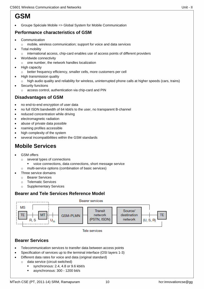
Bearer and Tele Services Reference Model
Bearer Services
Telecommunication services to transfer data between access points
Specification of services up to the terminal interface (OSI layers 1-3)
Different data rates for voice and data (original standard)
o data service (circuit switched)
synchronous: 2.4, 4.8 or 9.6 kbit/s
asynchronous: 300 - 1200 bit/s
CS601 Wireless Communication and Networks Unit - II
MTech CSE (PT, 2011-14) SRM, Ramapuram 11 hcr:innovationcse@gg
o data service (packet switched)
synchronous: 2.4, 4.8 or 9.6 kbit/s
asynchronous: 300 - 9600 bit/s
Tele Services
Telecommunication services that enable voice communication via mobile phones
All these basic services have to obey cellular functions, security measurements etc.
mobile telephony
Emergency number
o common number throughout Europe (112); mandatory for all service providers; free of charge;
connection with the highest priority (preemption of other connections possible)
Multinumbering
o several ISDN phone numbers per user possible
Non-Voice-Teleservices
o group 3 fax, voice mailbox, electronic mail, Short Message Service (SMS)
Supplementary services
Services in addition to the basic services, cannot be offered stand-alone
Similar to ISDN services besides lower bandwidth due to the radio link
May differ between different service providers, countries and protocol versions
Important services
o identification: forwarding of caller number
o suppression of number forwarding
o automatic call-back
o conferencing with up to 7 participants
o locking of the mobile terminal (incoming or outgoing calls)
GSM SYSTEM ARCHITECTURE GSM is a PLMN (Public Land Mobile Network)
several providers setup mobile networks following the GSM standard within each country
components
o MS (mobile station)
o BS (base station)
o MSC (mobile switching center)
o LR (location register)
subsystems
o RSS (radio subsystem): covers all radio aspects
o NSS (network and switching subsystem): call forwarding, handover, switching
o OSS (operation subsystem): management of the network
Radio Sub System (RSS)
All radio specific entities
Mobile Stations (MS)
o all user equipment and software needed for communication with a GSM network
o Subscriber Identity Module (SIM)
all user-specific data that is relevant to GSM
o International Mobile Equipment Identity (IMEI)
o Personal Identity Number (PIN)
o PIN Unblocking Key (PUK)
o Authentication Key Ki
o Cipher Key Kc
o International Mobile Subscriber Identity (IMSI)
o Temporary Mobile Subscriber Identity (TMSI)
o Location Area Identification (LAI)
Base Station Subsystem (BSS)
o controlled by a base station controller (BSC)
CS601 Wireless Communication and Networks Unit - II
MTech CSE (PT, 2011-14) SRM, Ramapuram 12 hcr:innovationcse@gg
o functions necessary to maintain radio connections to an MS,
o coding/decoding of voice
o rate adaptation to/from the wireless network part
o contains several BTSs
Base Transceiver Station (BTS)
o can form a radio cell or, several cells using sectorized antennas
o connected to MS via the Um interface (ISDN U interface for mobile use)
o connected to the BSC via the Abis interface.
Base Station Controller (BSC)
o manages the BTSs
o reserves radio frequencies
o handles the handover from one BTS to another within the BSS
o performs paging of the MS
o multiplexes the radio channels onto the fixed network connections at the A interface
O interface
o Signalling System No. 7 (SS7) based on X.25 (dashed lines)
A interface
o circuit-switched PCM-30 systems
Network and Switching Subsystem (NSS)
Mobile services switching center (MSC)
o Gateway MSC (GMSC)
additional connections to other fixed networks, such as PSTN and ISDN
o Interworking Functions (IWF)
Used to connect to public data networks (PDN) such as X.25.
o Standard Signaling System No. 7 (SS7)
o The MSC (mobile switching center) plays a central role in GSM
switching functions
additional functions for mobility support
management of network resources
interworking functions via Gateway MSC (GMSC)
integration of several databases
Functions of a MSC
specific functions for paging and call forwarding
termination of SS7 (signaling system no. 7)
mobility specific signaling
location registration and forwarding of location information
provision of new services (fax, data calls)
support of short message service (SMS)
generation and forwarding of accounting and billing information
Home Location Register (HLR)
o Mobile Subscriber ISDN number (MSISDN)
o International Mobile Subscriber Identity (IMSI)
o Location Area (LA)
o Mobile Subscriber Roaming Number (MSRN)
Visitor Location Register (VLR)
o local database for a subset of user data, data about all user currently in the domain of the VLR
CS601 Wireless Communication and Networks Unit - II
MTech CSE (PT, 2011-14) SRM, Ramapuram 13 hcr:innovationcse@gg
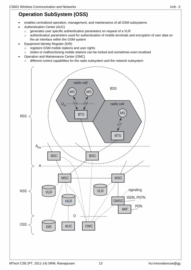
Operation SubSystem (OSS)
enables centralized operation, management, and maintenance of all GSM subsystems
Authentication Center (AUC)
o generates user specific authentication parameters on request of a VLR
o authentication parameters used for authentication of mobile terminals and encryption of user data on
the air interface within the GSM system
Equipment Identity Register (EIR)
o registers GSM mobile stations and user rights
o stolen or malfunctioning mobile stations can be locked and sometimes even localized
Operation and Maintenance Center (OMC)
o different control capabilities for the radio subsystem and the network subsystem
CS601 Wireless Communication and Networks Unit - II
MTech CSE (PT, 2011-14) SRM, Ramapuram 14 hcr:innovationcse@gg
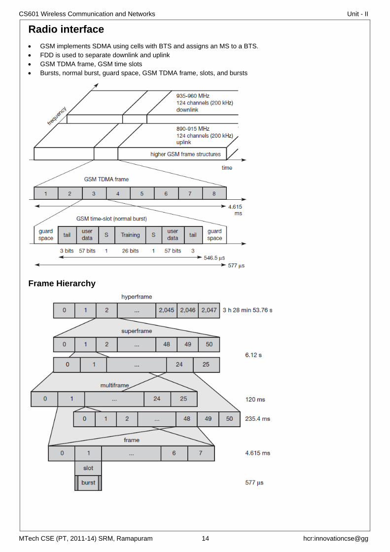
Radio interface
GSM implements SDMA using cells with BTS and assigns an MS to a BTS.
FDD is used to separate downlink and uplink
GSM TDMA frame, GSM time slots
Bursts, normal burst, guard space, GSM TDMA frame, slots, and bursts
Frame Hierarchy
CS601 Wireless Communication and Networks Unit - II
MTech CSE (PT, 2011-14) SRM, Ramapuram 15 hcr:innovationcse@gg
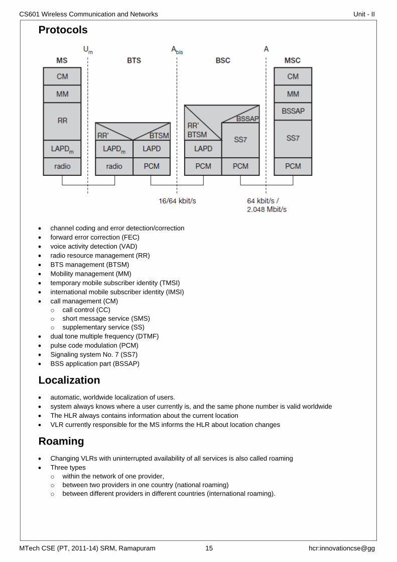
Protocols
channel coding and error detection/correction
forward error correction (FEC)
voice activity detection (VAD)
radio resource management (RR)
BTS management (BTSM)
Mobility management (MM)
temporary mobile subscriber identity (TMSI)
international mobile subscriber identity (IMSI)
call management (CM)
o call control (CC)
o short message service (SMS)
o supplementary service (SS)
dual tone multiple frequency (DTMF)
pulse code modulation (PCM)
Signaling system No. 7 (SS7)
BSS application part (BSSAP)
Localization
automatic, worldwide localization of users.
system always knows where a user currently is, and the same phone number is valid worldwide
The HLR always contains information about the current location
VLR currently responsible for the MS informs the HLR about location changes
Roaming
Changing VLRs with uninterrupted availability of all services is also called roaming
Three types
o within the network of one provider,
o between two providers in one country (national roaming)
o between different providers in different countries (international roaming).
CS601 Wireless Communication and Networks Unit - II
MTech CSE (PT, 2011-14) SRM, Ramapuram 16 hcr:innovationcse@gg
To locate an MS and to address the MS, several numbers are needed
Mobile station international ISDN number (MSISDN)
o follows the ITU-T standard E.164 for addresses as it is also used in fixed ISDN networks
o Consists of
country code (CC)
national destination code (NDC)
subscriber number (SN)
o e.g., +49 179 1234567
49 for Germany
179 for the address of the network provider
International mobile subscriber identity (IMSI)
o Consists of
a mobile country code (MCC)
the mobile network code (MNC)
the mobile subscriber identification number (MSIN)
Temporary mobile subscriber identity (TMSI)
o To hide the IMSI
o GSM uses the 4 byte TMSI for local subscriber identification
o a VLR may change the TMSI periodically
Mobile station roaming number (MSRN)
o hides the identity and location of a subscriber
o contains
the current visitor country code (VCC),
the visitor national destination code (VNDC)
the identification of the current MSC together with the subscriber number
o helps the HLR to find a subscriber for an incoming call
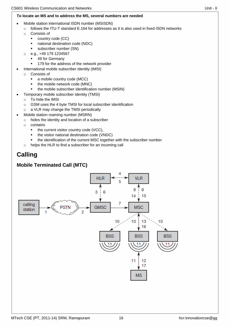
Calling
Mobile Terminated Call (MTC)
CS601 Wireless Communication and Networks Unit - II
MTech CSE (PT, 2011-14) SRM, Ramapuram 17 hcr:innovationcse@gg
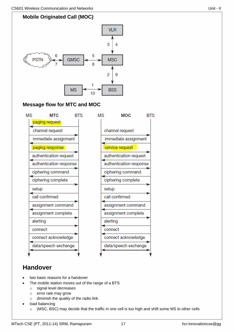
Mobile Originated Call (MOC)
Message flow for MTC and MOC
Handover
two basic reasons for a handover
The mobile station moves out of the range of a BTS
o signal level decreases
o error rate may grow
o diminish the quality of the radio link
load balancing
o (MSC, BSC) may decide that the traffic in one cell is too high and shift some MS to other cells
CS601 Wireless Communication and Networks Unit - II
MTech CSE (PT, 2011-14) SRM, Ramapuram 18 hcr:innovationcse@gg
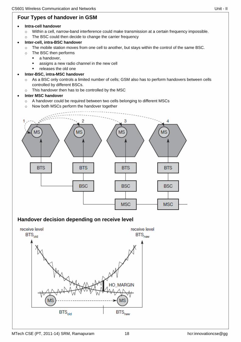
Four Types of handover in GSM
Intra-cell handover
o Within a cell, narrow-band interference could make transmission at a certain frequency impossible.
o The BSC could then decide to change the carrier frequency
Inter-cell, intra-BSC handover
o The mobile station moves from one cell to another, but stays within the control of the same BSC.
o The BSC then performs
a handover,
assigns a new radio channel in the new cell
releases the old one
Inter-BSC, intra-MSC handover
o As a BSC only controls a limited number of cells; GSM also has to perform handovers between cells
controlled by different BSCs.
o This handover then has to be controlled by the MSC
Inter MSC handover
o A handover could be required between two cells belonging to different MSCs
o Now both MSCs perform the handover together
Handover decision depending on receive level
CS601 Wireless Communication and Networks Unit - II
MTech CSE (PT, 2011-14) SRM, Ramapuram 19 hcr:innovationcse@gg
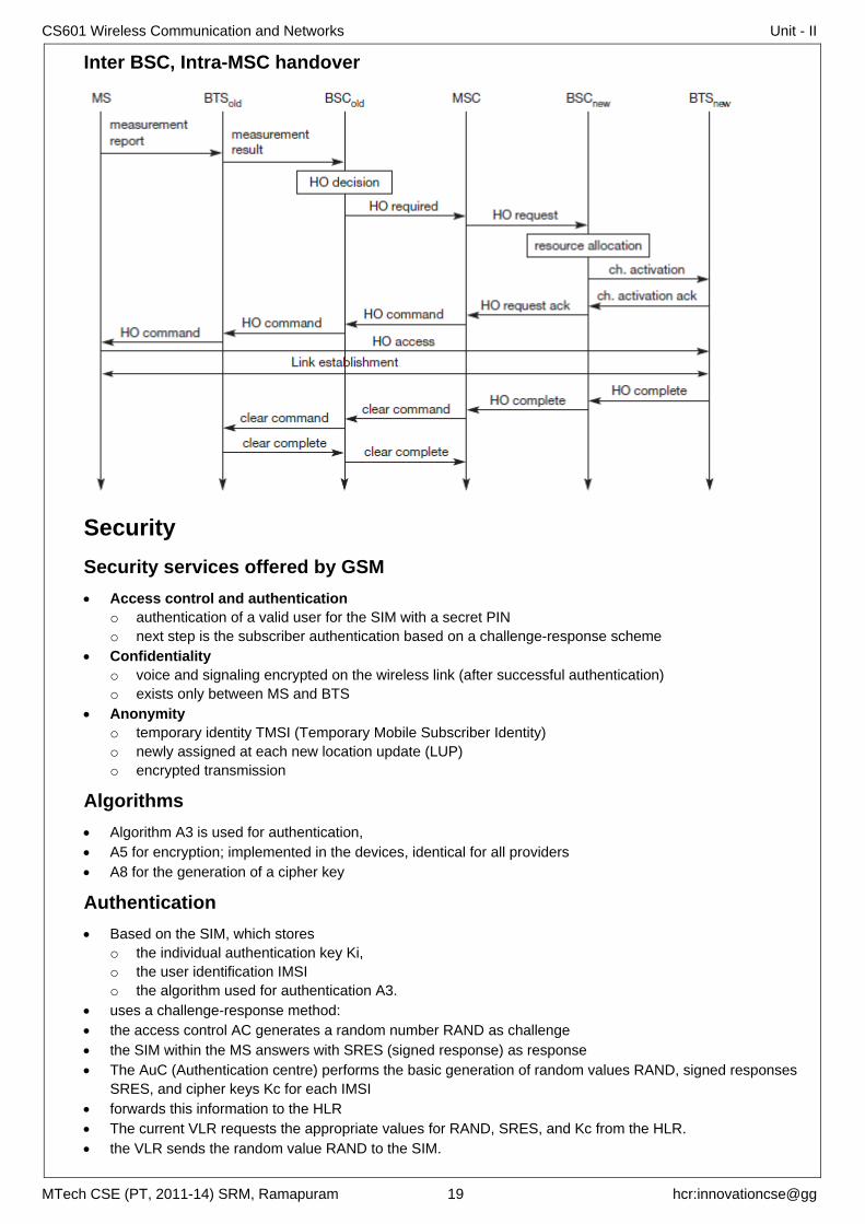
Inter BSC, Intra-MSC handover
Security
Security services offered by GSM
Access control and authentication
o authentication of a valid user for the SIM with a secret PIN
o next step is the subscriber authentication based on a challenge-response scheme
Confidentiality
o voice and signaling encrypted on the wireless link (after successful authentication)
o exists only between MS and BTS
Anonymity
o temporary identity TMSI (Temporary Mobile Subscriber Identity)
o newly assigned at each new location update (LUP)
o encrypted transmission
Algorithms
Algorithm A3 is used for authentication,
A5 for encryption; implemented in the devices, identical for all providers
A8 for the generation of a cipher key
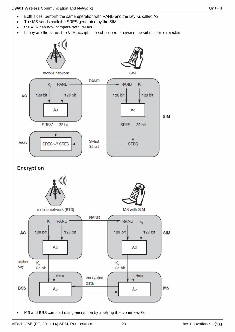
Authentication
Based on the SIM, which stores
o the individual authentication key Ki,
o the user identification IMSI
o the algorithm used for authentication A3.
uses a challenge-response method:
the access control AC generates a random number RAND as challenge
the SIM within the MS answers with SRES (signed response) as response
The AuC (Authentication centre) performs the basic generation of random values RAND, signed responses
SRES, and cipher keys Kc for each IMSI
forwards this information to the HLR
The current VLR requests the appropriate values for RAND, SRES, and Kc from the HLR.
the VLR sends the random value RAND to the SIM.
CS601 Wireless Communication and Networks Unit - II
MTech CSE (PT, 2011-14) SRM, Ramapuram 20 hcr:innovationcse@gg
Both sides, perform the same operation with RAND and the key Ki, called A3.
The MS sends back the SRES generated by the SIM;
the VLR can now compare both values.
If they are the same, the VLR accepts the subscriber, otherwise the subscriber is rejected.
Encryption
MS and BSS can start using encryption by applying the cipher key Kc
CS601 Wireless Communication and Networks Unit - II
MTech CSE (PT, 2011-14) SRM, Ramapuram 21 hcr:innovationcse@gg
Kc is generated using the individual key Ki and a random value by applying the algorithm A8.
the SIM in the MS and the network both calculate the same Kc
The key Kc itself is not transmitted over the air interface
MS and BTS can now encrypt and decrypt data using the algorithm A5 and the cipher key Kc.
New data services
High Speed Circuit Switched Data (HSCSD)
higher data rates are achieved by bundling several TCHs
air interface user rate (AIUR)
For n channels, HSCSD requires n times signaling during handover, connection
setup and release. Each channel is treated separately
General Packet Radio Service (GPRS)
packet mode transfer for applications that exhibit traffic patterns such as frequent transmission of small
volumes (e.g., typical web requests) or infrequent transmissions of small or medium volumes (e.g., typical
web responses)
point-to-point (PTP) packet transfer service
PTP connection oriented network service (PTP-CONS)
PTP connectionless network service (PTP-CLNS)
QoS-profile
o service precedence (high, normal, low),
o reliability class and delay class of the transmission,
o user data throughput.
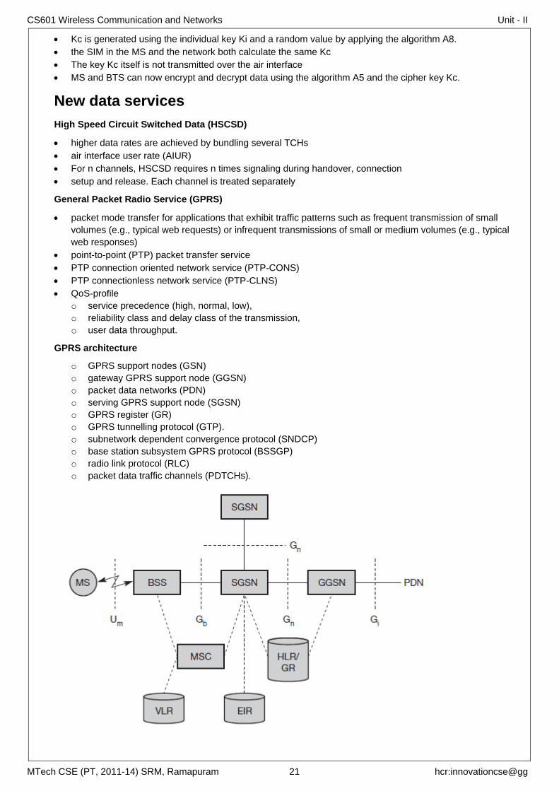
GPRS architecture
o GPRS support nodes (GSN)
o gateway GPRS support node (GGSN)
o packet data networks (PDN)
o serving GPRS support node (SGSN)
o GPRS register (GR)
o GPRS tunnelling protocol (GTP).
o subnetwork dependent convergence protocol (SNDCP)
o base station subsystem GPRS protocol (BSSGP)
o radio link protocol (RLC)
o packet data traffic channels (PDTCHs).
CS601 Wireless Communication and Networks Unit - II
MTech CSE (PT, 2011-14) SRM, Ramapuram 22 hcr:innovationcse@gg
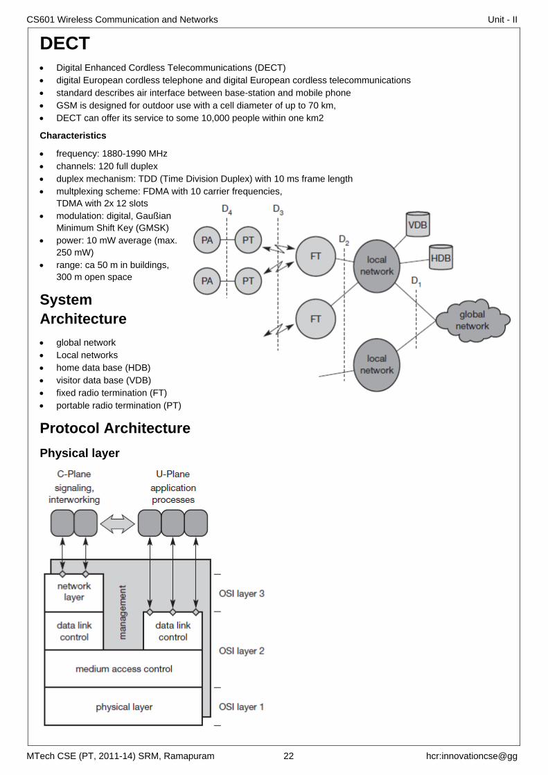
DECT Digital Enhanced Cordless Telecommunications (DECT)
digital European cordless telephone and digital European cordless telecommunications
standard describes air interface between base-station and mobile phone
GSM is designed for outdoor use with a cell diameter of up to 70 km,
DECT can offer its service to some 10,000 people within one km2
Characteristics
frequency: 1880-1990 MHz
channels: 120 full duplex
duplex mechanism: TDD (Time Division Duplex) with 10 ms frame length
multplexing scheme: FDMA with 10 carrier frequencies,
TDMA with 2x 12 slots
modulation: digital, Gaußian
Minimum Shift Key (GMSK)
power: 10 mW average (max.
250 mW)
range: ca 50 m in buildings,
300 m open space
System
Architecture
global network
Local networks
home data base (HDB)
visitor data base (VDB)
fixed radio termination (FT)
portable radio termination (PT)
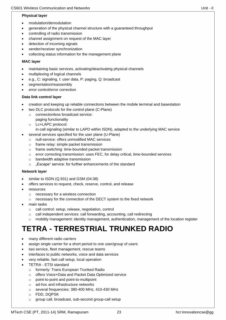
Protocol Architecture
Physical layer
CS601 Wireless Communication and Networks Unit - II
MTech CSE (PT, 2011-14) SRM, Ramapuram 23 hcr:innovationcse@gg
Physical layer
modulation/demodulation
generation of the physical channel structure with a guaranteed throughput
controlling of radio transmission
channel assignment on request of the MAC layer
detection of incoming signals
sender/receiver synchronization
collecting status information for the management plane
MAC layer
maintaining basic services, activating/deactivating physical channels
multiplexing of logical channels
e.g., C: signaling, I: user data, P: paging, Q: broadcast
segmentation/reassembly
error control/error correction
Data link control layer
creation and keeping up reliable connections between the mobile terminal and basestation
two DLC protocols for the control plane (C-Plane)
o connectionless broadcast service:
paging functionality
o Lc+LAPC protocol:
in-call signaling (similar to LAPD within ISDN), adapted to the underlying MAC service
several services specified for the user plane (U-Plane)
o null-service: offers unmodified MAC services
o frame relay: simple packet transmission
o frame switching: time-bounded packet transmission
o error correcting transmission: uses FEC, for delay critical, time-bounded services
o bandwidth adaptive transmission
o „Escape“ service: for further enhancements of the standard
Network layer
similar to ISDN (Q.931) and GSM (04.08)
offers services to request, check, reserve, control, and release
resources
o necessary for a wireless connection
o necessary for the connection of the DECT system to the fixed network
main tasks
o call control: setup, release, negotiation, control
o call independent services: call forwarding, accounting, call redirecting
o mobility management: identity management, authentication, management of the location register
TETRA - TERRESTRIAL TRUNKED RADIO many different radio carriers
assign single carrier for a short period to one user/group of users
taxi service, fleet management, rescue teams
interfaces to public networks, voice and data services
very reliable, fast call setup, local operation
TETRA - ETSI standard
o formerly: Trans European Trunked Radio
o offers Voice+Data and Packet Data Optimized service
o point-to-point and point-to-multipoint
o ad-hoc and infrastructure networks
o several frequencies: 380-400 MHz, 410-430 MHz
o FDD, DQPSK
o group call, broadcast, sub-second group-call setup
CS601 Wireless Communication and Networks Unit - II
MTech CSE (PT, 2011-14) SRM, Ramapuram 24 hcr:innovationcse@gg
SATELLITE SYSTEMS
Applications
Traditional
Weather forecasting
o infra red or visible light
Radio and TV broadcast satellites
o it is cheaper to install and, in most cases, no extra fees have to be paid for this service
Military satellites
o much safer from attack by enemies
Satellites for navigation
o global positioning system (GPS)
Mobile Communication
Global telephone backbones
o big cable in the sky
o being replaced by fiber optical cables crossing the oceans
o one-way, single-hop time delay of 0.25 s
Connections for remote or developing areas
o many places all over the world do not have direct wired connection to internet
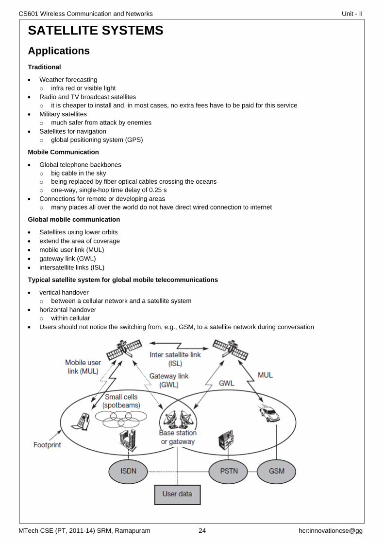
Global mobile communication
Satellites using lower orbits
extend the area of coverage
mobile user link (MUL)
gateway link (GWL)
intersatellite links (ISL)
Typical satellite system for global mobile telecommunications
vertical handover
o between a cellular network and a satellite system
horizontal handover
o within cellular
Users should not notice the switching from, e.g., GSM, to a satellite network during conversation
CS601 Wireless Communication and Networks Unit - II
MTech CSE (PT, 2011-14) SRM, Ramapuram 25 hcr:innovationcse@gg
Basics
Depending on the application, these orbits can be circular or elliptical
Satellites in circular orbits always keep the same distance to the earth’s surface following a simple law
m is the mass of the satellite;
R is the radius of earth with R = 6,370 km;
r is the distance of the satellite to the centre of the earth
f is the frequency of the rotation.
To keep the satellite in a stable circular orbit, both forces must be equal Fg = Fc
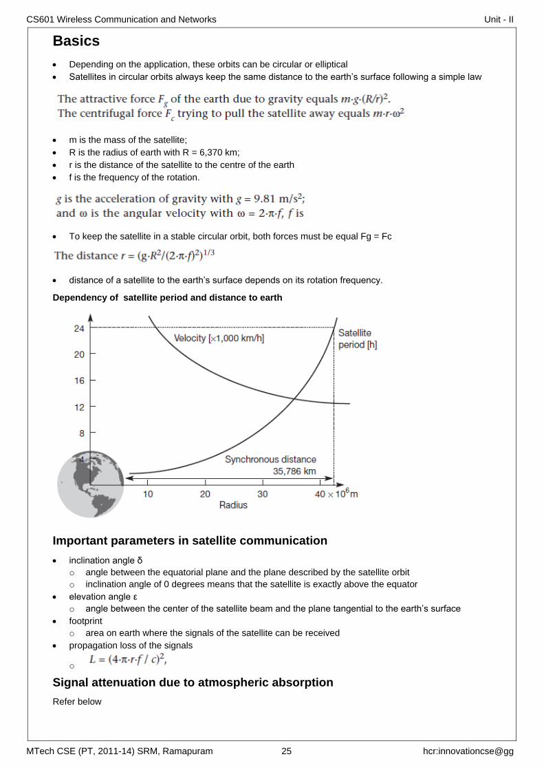
distance of a satellite to the earth’s surface depends on its rotation frequency.
Dependency of satellite period and distance to earth
Important parameters in satellite communication
inclination angle δ
o angle between the equatorial plane and the plane described by the satellite orbit
o inclination angle of 0 degrees means that the satellite is exactly above the equator
elevation angle ε
o angle between the center of the satellite beam and the plane tangential to the earth’s surface
footprint
o area on earth where the signals of the satellite can be received
propagation loss of the signals
o
Signal attenuation due to atmospheric absorption
Refer below
CS601 Wireless Communication and Networks Unit - II
MTech CSE (PT, 2011-14) SRM, Ramapuram 26 hcr:innovationcse@gg
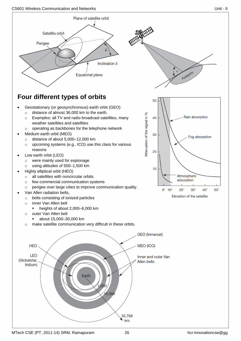
Four different types of orbits
Geostationary (or geosynchronous) earth orbit (GEO)
o distance of almost 36,000 km to the earth.
o Examples: all TV and radio broadcast satellites, many
weather satellites and satellites
o operating as backbones for the telephone network
Medium earth orbit (MEO)
o distance of about 5,000–12,000 km
o upcoming systems (e.g., ICO) use this class for various
reasons
Low earth orbit (LEO)
o were mainly used for espionage
o using altitudes of 500–1,500 km
Highly elliptical orbit (HEO)
o all satellites with noncircular orbits.
o few commercial communication systems
o perigee over large cities to improve communication quality.
Van Allen radiation belts,
o belts consisting of ionized particles
o inner Van Allen belt
heights of about 2,000–6,000 km
o outer Van Allen belt
about 15,000–30,000 km
o make satellite communication very difficult in these orbits.
CS601 Wireless Communication and Networks Unit - II
MTech CSE (PT, 2011-14) SRM, Ramapuram 27 hcr:innovationcse@gg
GEO
Orbit
o 35.786 km distance to earth surface, equatorial plane (inclination 0°)
complete rotation exactly one day, satellite is synchronous to earth rotation
Advantages
o can use fixed antenna positions, no adjusting is needed.
o ideal for TV and radio broadcasting.
o do not need a handover due to the large footprint
o do not exhibit any Doppler shift because the relative movement is zero.
Disadvantages:
o Northern or southern regions of the earth have more problems receiving these satellites due to the low
elevation above a latitude of 60°, i.e., larger antennas are needed in this case.
o Shading of the signals in cities due to high buildings and the low elevation further away from the
equator limit transmission quality.
o The transmit power needed is relatively high (some 10 W), problems for battery powered devices.
o Cannot be used for small mobile phones.
o high latency of over 0.25 s one-way – biggest problem for voice and also data communication
o many retransmission schemes which are known from fixed networks fail.
o Due to the large footprint, either frequencies cannot be reused or the GEO satellite needs special
antennas focusing on a smaller footprint.
o Transferring a GEO into orbit is very expensive
LEO
Orbit ca. 500 - 1500 km above earth surface
typical duration of LEO periods are 95 to 120 minutes
provide a high quality communication link by ensuring a high elevation for every spot on earth
will only be visible from the earth for around ten minutes
Further classification into
o Little LEOs with low bandwidth services (some 100 bit/s)
o big LEOs (some 1,000 bit/s)
o broadband LEOs with plans reaching into the Mbit/s range
Advantages:
o using low transmit power in the range of 1W
o The delay for packets delivered via a LEO is relatively low (approx 10 ms)
o Smaller footprints of LEOs allow for better frequency reuse
o LEOs can provide a much higher elevation in polar regions and so better global coverage.
Disadvantages
o handover necessary from one satellite to another
o many satellites necessary for global coverage
o more complex systems due to moving satellites
MEO
Orbit ca. 5000 - 12000 km above earth surface
Advantages:
o the system only requires a dozen satellites for global coverage
o move more slowly relative to the earth’s rotation allowing a simpler system design
o satellite periods are about six hours
o Depending on the inclination, a MEO can cover larger populations, so requiring fewer handovers.
Disadvantages:
o delay increases to about 70–80 ms.
o need higher transmit power
o need special antennas for smaller footprints.
CS601 Wireless Communication and Networks Unit - II
MTech CSE (PT, 2011-14) SRM, Ramapuram 28 hcr:innovationcse@gg
Routing
Satellites offering Inter Satellite Link (ISL)
o traffic can be routed between the satellites.
o one user sends data up to a satellite
o the satellite forwards it to the one responsible for the receiver via other satellites.
o The last satellite now sends the data down to the earth
o only one uplink and one downlink per direction is needed
o The ability of routing within the satellite network reduces the number of gateways needed on earth.
Without ISL
o all traffic is relayed to earth, routed there relayed back to a satellite.
Localization
similar to that of terrestrial cellular networks
Home Location Register (HLR)
o stores all static information about a user with current location
Visitor Location Register (VLR)
o The last known location of a mobile user
Satellite User Mapping Register (SUMR)
o stores the current position of satellites
o a mapping of each user to the current satellite
Registration of a mobile station
o initially sends a signal which one or several satellites can receive.
o Satellites receiving such a signal report this event to a gateway.
o The gateway can now determine the location of the user via the location of the satellites.
o User data is requested from the user’s HLR, VLR and SUMR are updated
Calling a mobile station
o localization using HLR/VLR similar to GSM
o connection setup using the appropriate satellite
Handover in satellite systems
caused by the movement of the satellites
Intra satellite handover
o handover from one spot beam to another
o mobile station still in the footprint of the satellite, but in another cell
Inter satellite handover
o handover from one satellite to another satellite
o mobile station leaves the footprint of one satellite
Gateway handover
o Handover from one gateway to another
o mobile station still in the footprint of a satellite, but gateway leaves the footprint
Inter system handover
o Handover from the satellite network to a terrestrial cellular network
o mobile station can reach a terrestrial network again which might be cheaper, has a lower latency etc
Comments & Feedback
Thanks to my family members who supported me while I spent hours and hours to prepare this.
Your feedback is welcome at [email protected]