Embed Size (px)
Citation preview
UNIT II
MOBILE TELECOMMUNICATION SYSTEM
By
N.Gopinath
AP/CSE
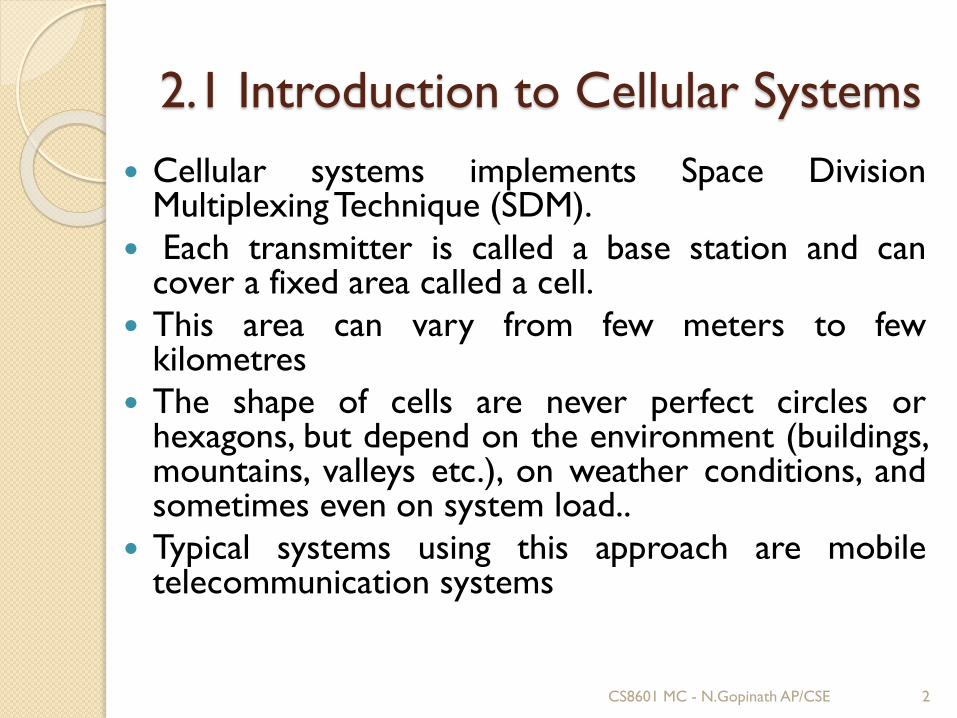
2.1 Introduction to Cellular Systems
Cellular systems implements Space DivisionMultiplexing Technique (SDM).
Each transmitter is called a base station and cancover a fixed area called a cell.
This area can vary from few meters to fewkilometres
The shape of cells are never perfect circles orhexagons, but depend on the environment (buildings,mountains, valleys etc.), on weather conditions, andsometimes even on system load..
Typical systems using this approach are mobiletelecommunication systems
2CS8601 MC - N.Gopinath AP/CSE
CS8601 MC - N.Gopinath AP/CSE 3
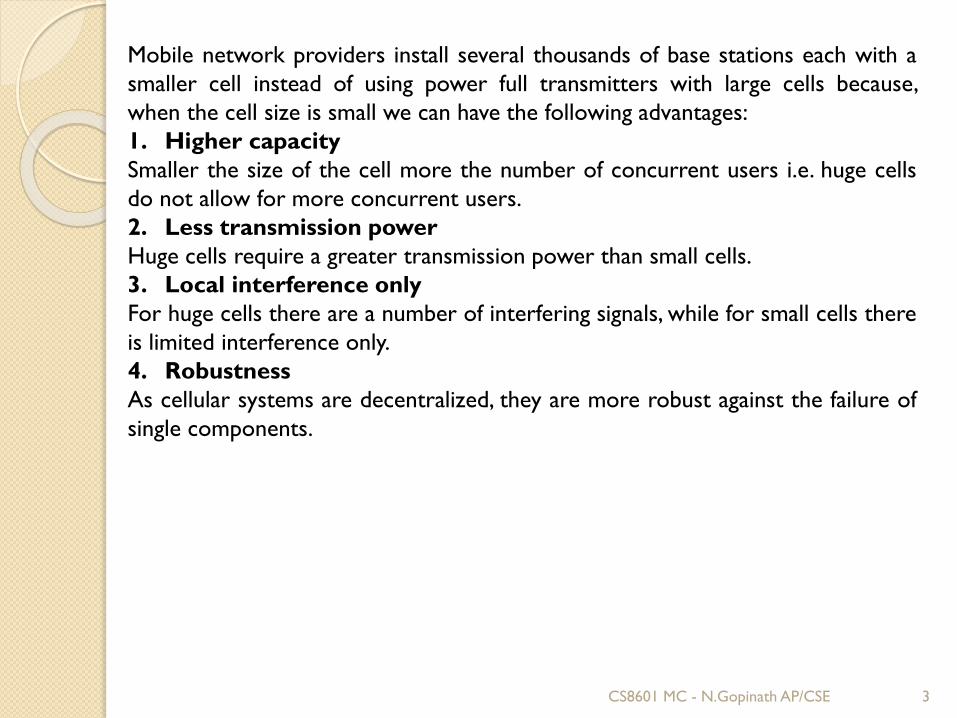
Mobile network providers install several thousands of base stations each with a
smaller cell instead of using power full transmitters with large cells because,
when the cell size is small we can have the following advantages:
1. Higher capacity
Smaller the size of the cell more the number of concurrent users i.e. huge cells
do not allow for more concurrent users.
2. Less transmission power
Huge cells require a greater transmission power than small cells.
3. Local interference only
For huge cells there are a number of interfering signals, while for small cells there
is limited interference only.
4. Robustness
As cellular systems are decentralized, they are more robust against the failure of
single components.
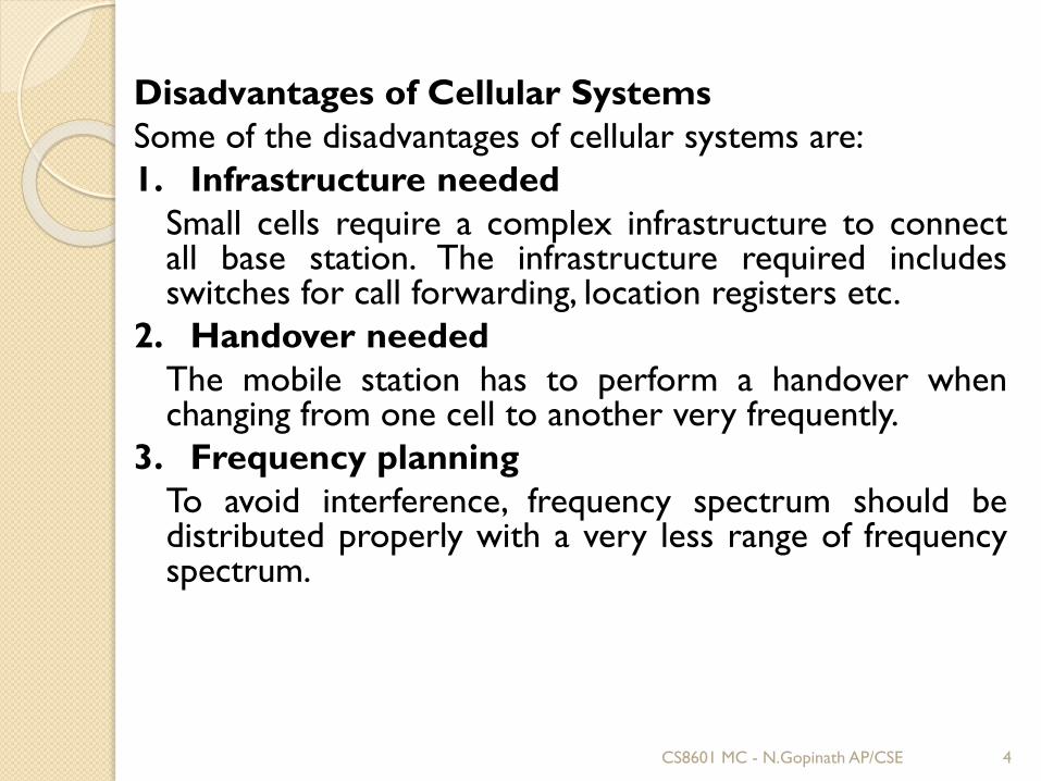
Disadvantages of Cellular Systems
Some of the disadvantages of cellular systems are:
1. Infrastructure needed
Small cells require a complex infrastructure to connectall base station. The infrastructure required includesswitches for call forwarding, location registers etc.
2. Handover needed
The mobile station has to perform a handover whenchanging from one cell to another very frequently.
3. Frequency planning
To avoid interference, frequency spectrum should bedistributed properly with a very less range of frequencyspectrum.
CS8601 MC - N.Gopinath AP/CSE 4
Frequency Planning:
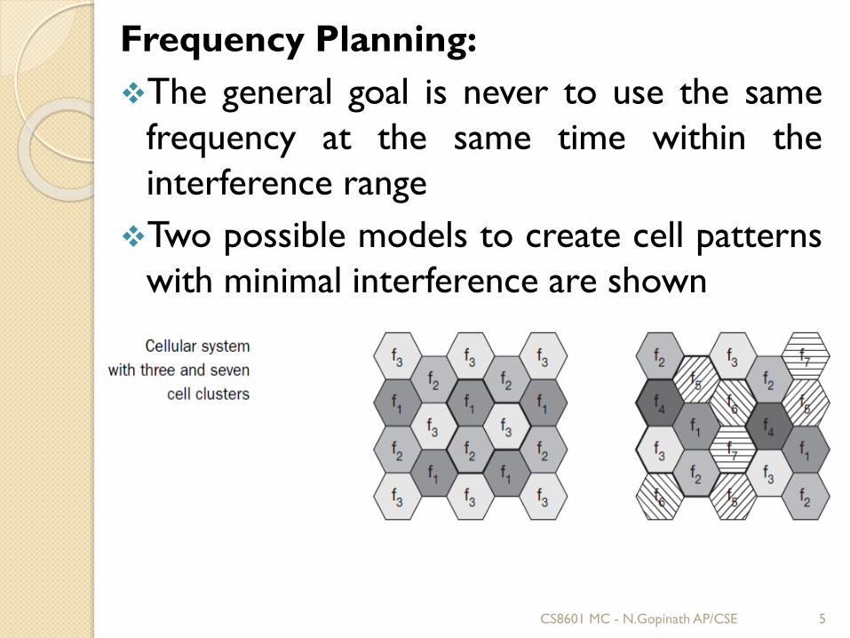
❖The general goal is never to use the same
frequency at the same time within the
interference range
❖Two possible models to create cell patterns
with minimal interference are shown
CS8601 MC - N.Gopinath AP/CSE 5
Cells are combined in clusters – on the leftside three cells form a cluster, on the rightside seven cells form a cluster. All cells withina cluster use disjointed sets of frequencies.
The hexagonal pattern is chosen as a simpleway of illustrating the model.
This pattern also shows the repetition of thesame frequency sets.
The transmission power of a sender has tobe limited to avoid interference with thenext cell using the same frequencies.
CS8601 MC - N.Gopinath AP/CSE 6
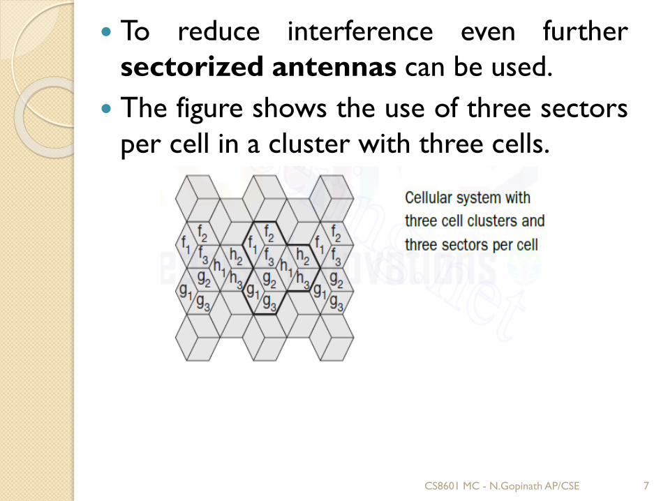
To reduce interference even further
sectorized antennas can be used.
The figure shows the use of three sectors
per cell in a cluster with three cells.
CS8601 MC - N.Gopinath AP/CSE 7
The fixed assignment of frequencies to cellclusters and cells respectively, is not veryefficient if traffic load varies.
For instance, in the case of a heavy load inone cell and a light load in a neighbouringcell, it could make sense to ‘borrow’frequencies.
Cells with more traffic are dynamicallyallotted more frequencies. This scheme isknown as Borrowing Channel Allocation(BCA)
CS8601 MC - N.Gopinath AP/CSE 8
A dynamic channel allocation (DCA)scheme has been implemented in DigitalEnhanced Cordless Telecommunication(DECT)
In this scheme, frequencies can only beborrowed, but it is also possible to freelyassign frequencies to cells.
With dynamic assignment of frequencies tocells, the danger of interference with cellsusing the same frequency exists.
The ‘borrowed’ frequency can be blocked inthe surrounding cells.
CS8601 MC - N.Gopinath AP/CSE 9
2.2 GSM (Global System for Mobile
Communications)
GSM is the most successful digital mobiletelecommunication system in the world today.
It is used by over 800 million people in more than190 countries.
The Groupe Spéciale Mobile (GSM) wasfounded in 1982.
This system was soon named the Global Systemfor Mobile communications (GSM)
The primary goal of GSM was to provide a mobilephone system that allows users to roam throughoutEurope and provides voice services compatible toISDN and other PSTN systems.
CS8601 MC - N.Gopinath AP/CSE 10
GSM is a typical second generation system, replacing thefirst generation Analog systems, but not offering the highworldwide data rates that the third generation systems,such as UMTS, are promising.
GSM has initially been deployed in Europe using 890–915MHz for uplinks and 935–960 MHz for downlinks
This system is now also called GSM 900 to distinguish itfrom the later versions.
These versions comprise GSM at 1800 MHz (1710–1785MHz uplink, 1805–1880 MHz downlink), also called DCS(digital cellular system) 1800
The GSM system mainly used in the US at 1900 MHz(1850–1910 MHz uplink, 1930–1990 MHz downlink), alsocalled PCS (personal communications service) 1900
CS8601 MC - N.Gopinath AP/CSE 11
A GSM system that has been introduced in severalEuropean countries for railroad systems is GSM-Rail (GSM-R, 2002), (ETSI, 2002).
This system does not only use separate frequenciesbut offers many additional services which areunavailable using the public GSM system.
GSM-R offers 19 exclusive channels for railroadoperators for voice and data traffic. Special featuresof this system are, e.g., emergency calls withacknowledgements, voice group call service (VGCS),voice broadcast service (VBS).
The most sophisticated use of GSM-R is the controlof trains, switches, gates, and signals.
CS8601 MC - N.Gopinath AP/CSE 12
2.3 GSM Services and Architecture:
GSM has defined three different categories of
services:
❖Bearer services,
❖Tele- services,
❖Supplementary services.
CS8601 MC - N.Gopinath AP/CSE 13

A mobile station MS is connected to the GSM public landmobile network (PLMN) via the Um interface.
This network is connected to transit networks, e.g.,integrated services digital network (ISDN) or traditionalpublic switched telephone network (PSTN).
There might be an additional network, the source/destinationnetwork, before another terminal TE is connected.
Interfaces like U, S, and R in case of ISDN have not beendefined for all networks, so it depends on the specific networkwhich interface is used as a reference for the transparenttransmission of data.
The mobile termination (MT) performs all network specifictasks (TDMA, FDMA, coding etc.)
CS8601 MC - N.Gopinath AP/CSE 14
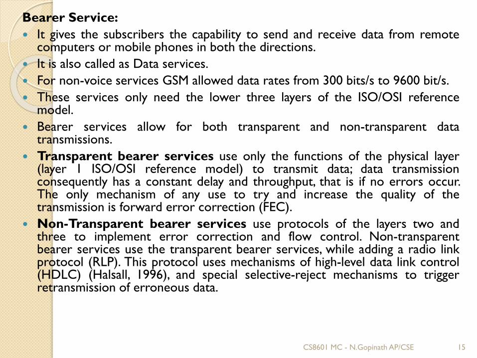
Bearer Service:
It gives the subscribers the capability to send and receive data from remotecomputers or mobile phones in both the directions.
It is also called as Data services.
For non-voice services GSM allowed data rates from 300 bits/s to 9600 bit/s.
These services only need the lower three layers of the ISO/OSI referencemodel.
Bearer services allow for both transparent and non-transparent datatransmissions.
Transparent bearer services use only the functions of the physical layer(layer 1 ISO/OSI reference model) to transmit data; data transmissionconsequently has a constant delay and throughput, that is if no errors occur.The only mechanism of any use to try and increase the quality of thetransmission is forward error correction (FEC).
Non-Transparent bearer services use protocols of the layers two andthree to implement error correction and flow control. Non-transparentbearer services use the transparent bearer services, while adding a radio linkprotocol (RLP). This protocol uses mechanisms of high-level data link control(HDLC) (Halsall, 1996), and special selective-reject mechanisms to triggerretransmission of erroneous data.
CS8601 MC - N.Gopinath AP/CSE 15
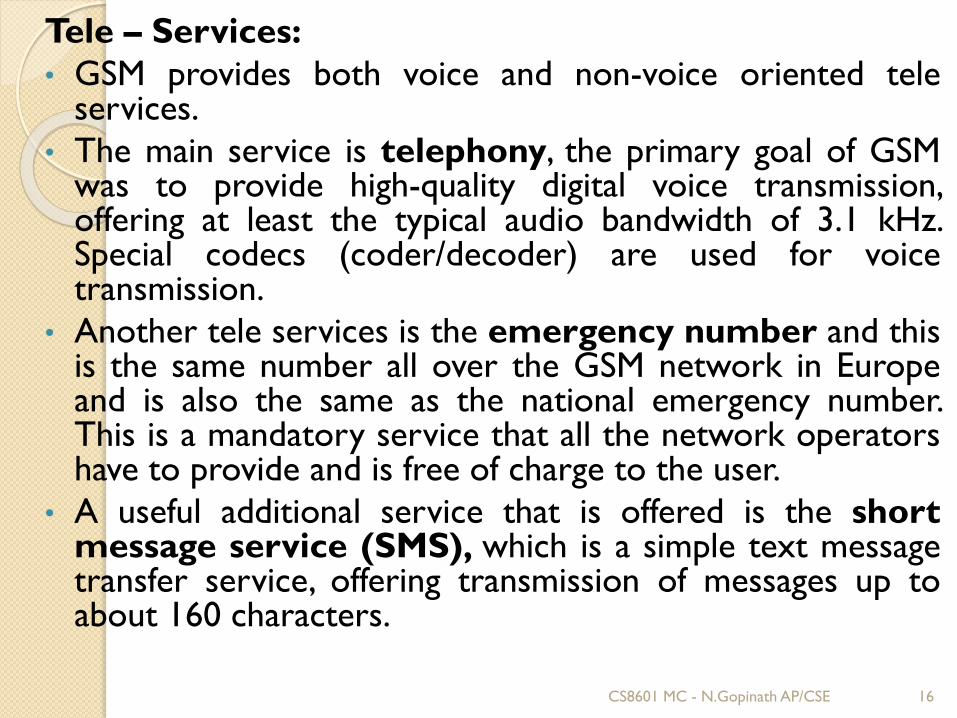
Tele – Services:
• GSM provides both voice and non-voice oriented teleservices.
• The main service is telephony, the primary goal of GSMwas to provide high-quality digital voice transmission,offering at least the typical audio bandwidth of 3.1 kHz.Special codecs (coder/decoder) are used for voicetransmission.
• Another tele services is the emergency number and thisis the same number all over the GSM network in Europeand is also the same as the national emergency number.This is a mandatory service that all the network operatorshave to provide and is free of charge to the user.
• A useful additional service that is offered is the shortmessage service (SMS), which is a simple text messagetransfer service, offering transmission of messages up toabout 160 characters.
CS8601 MC - N.Gopinath AP/CSE 16
Supplementary Services:
Further to bearer and tele services, GSM
network operators can also offer supplementary
services. These services offer enhancements to
the standard telephony service and may differ
from operator to operator, though typical
services available to the user are caller location
identifier (CLI), call forwarding, or redirection.
CS8601 MC - N.Gopinath AP/CSE 17
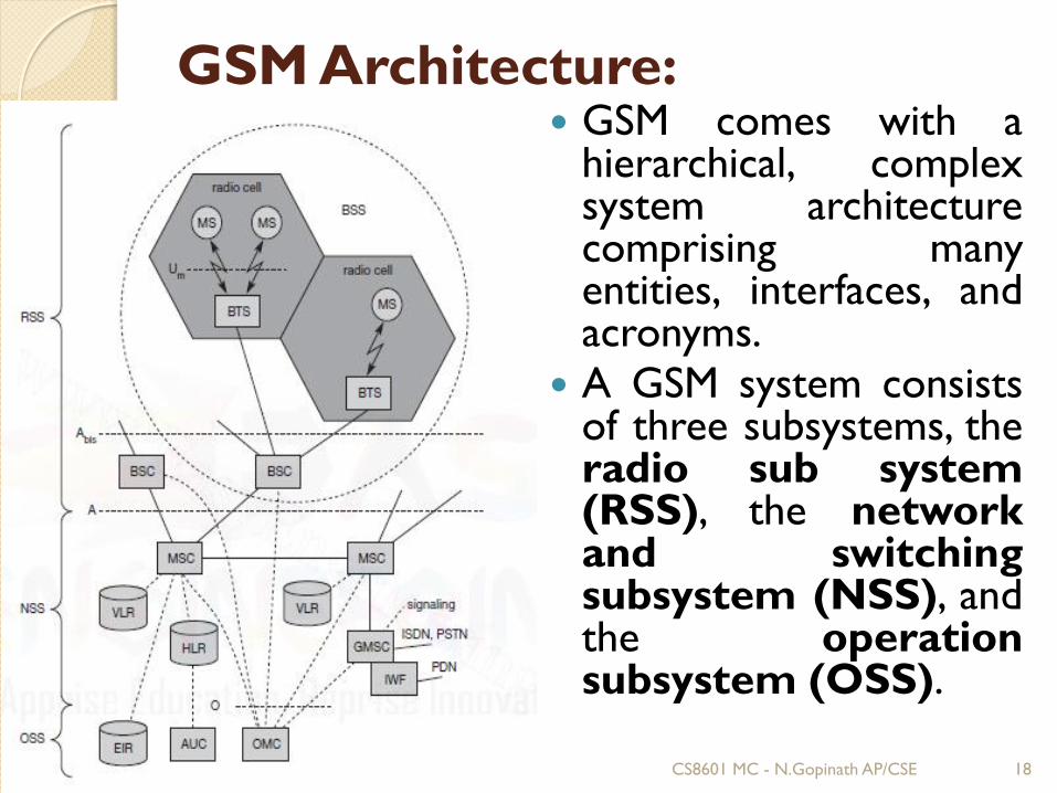
GSM Architecture: GSM comes with a
hierarchical, complexsystem architecturecomprising manyentities, interfaces, andacronyms.
A GSM system consistsof three subsystems, theradio sub system(RSS), the networkand switchingsubsystem (NSS), andthe operationsubsystem (OSS).
CS8601 MC - N.Gopinath AP/CSE 18
1. Radio Subsystem (RSS): comprises all radio specific entities, i.e., themobile stations (MS) and the base station subsystem (BSS). Thefigure shows the connection between the RSS and the NSS via the Ainterface (solid lines) and the connection to the OSS via the O interface(dashed lines).
❖ Base station subsystem (BSS): A GSM network comprises many BSSs,each controlled by a base station controller (BSC). The BSS performs allfunctions necessary to maintain radio connections to an MS,coding/decoding of voice, and rate adaptation to/from the wirelessnetwork part. Besides a BSC, the BSS contains several BTSs.
❖ Base station controllers (BSC): The BSC provides all the controlfunctions and physical links between the MSC and BTS. It is a high capacityswitch that provides functions such as handover, cell configuration data,and control of radio frequency (RF) power levels in BTS.
❖ Base transceiver station (BTS): The BTS handles the radio interfaceto the mobile station. A BTS can form a radio cell or, using sectorizedantennas, several and is connected to MS via the Um interface, and tothe BSC via the Abis interface. A group of BTS’s are controlled by anBSC.
CS8601 MC - N.Gopinath AP/CSE 19
2. Network Switching Subsystem: The NSS is responsible for performingcall processing and subscriber related functions. The switching systemincludes the following functional units:
❖ Home location register (HLR): It is a database used for storage andmanagement of subscriptions. HLR stores permanent data aboutsubscribers, including a subscribers service profile, location informationand activity status.
❖ Visitor location register (VLR): It is a database that containstemporary information about subscribers that is needed by the MSC inorder to service visiting subscribers. VLR is always integrated with theMSC.
Authentication center (AUC): A unit called the AUC providesauthentication and encryption parameters that verify the users identity andensure the confidentiality of each call.
Equipment identity register (EIR): It is a database that containsinformation about the identity of mobile equipment that prevents callsfrom stolen, unauthorized or defective mobile stations.
Mobile switching center (MSC): The MSC performs the telephonyswitching functions of the system. It controls calls to and from othertelephone and data systems.
CS8601 MC - N.Gopinath AP/CSE 20
3.Operation and Support system:
• The operations and maintenance center (OMC) is connected to allequipment in the switching system and to the BSC. Implementation ofOMC is called operation and support system (OSS).
• The purpose of OSS is to offer the customer cost-effective support forcentralized, regional and local operational and maintenance activities thatare required for a GSM network.
• The mobile station (MS) consists of the mobile equipment (the terminal)and a smart card called the Subscriber Identity Module (SIM). TheSIM provides personal mobility, so that the user can have access tosubscribed services irrespective of a specific terminal. By inserting the SIMcard into another GSM terminal, the user is able to receive calls at thatterminal, make calls from that terminal, and receive other subscribedservices.
• The mobile equipment is uniquely identified by the International MobileEquipment Identity (IMEI). The SIM card contains the InternationalMobile Subscriber Identity (IMSI) used to identify the subscriber tothe system, a secret key for authentication, and other information. The IMEIand the IMSI are independent, thereby allowing personal mobility. The SIMcard may be protected against unauthorized use by a password or personalidentity number.
CS8601 MC - N.Gopinath AP/CSE 21
2.4 GSM Protocols:
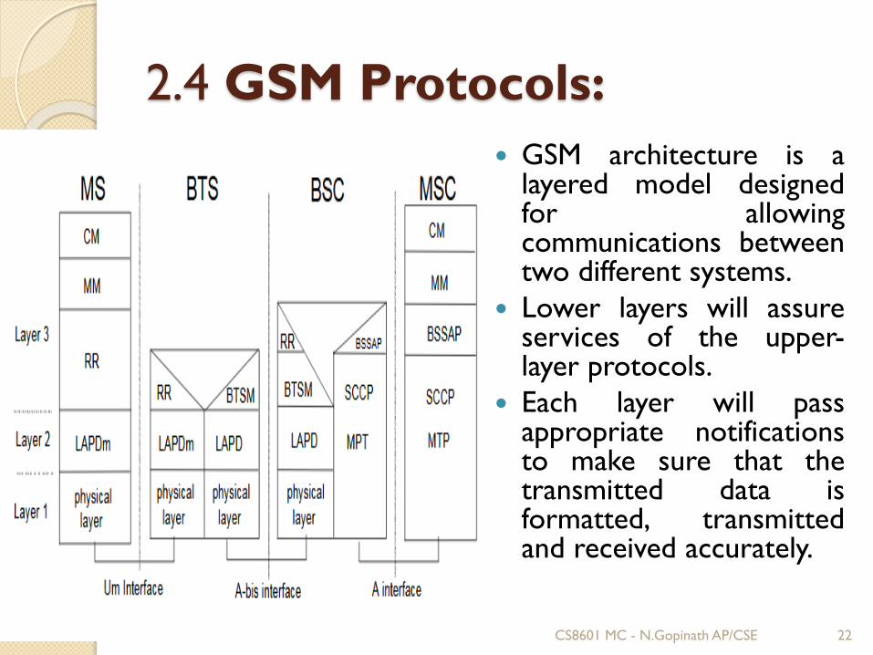
GSM architecture is alayered model designedfor allowingcommunications betweentwo different systems.
Lower layers will assureservices of the upper-layer protocols.
Each layer will passappropriate notificationsto make sure that thetransmitted data isformatted, transmittedand received accurately.
CS8601 MC - N.Gopinath AP/CSE 22
MS Protocols
Based on the interface, GSM signalling protocol will be assembled intothree general layers:
Layer 1 : Physical layer. It makes use of the channel structures over theair interface.
Layer 2 : Data-link layer. Across the Um interface, data-link layer is atailored version of Link access protocol for D channel (LAP-D)protocol used in ISDN, called Link access protocol on the Dm channel(LAP-Dm). Across the A interface, the Message Transfer Part (MTP),Layer 2 of SS7 is used.
Layer 3 : GSM signalling protocol’s third layer can be divided into threesub layers:
❖ Radio Resource Management (RR),
❖ Mobility Management (MM), and
❖ Connection Management (CM).
CS8601 MC - N.Gopinath AP/CSE 23
MS to BTS Protocols
The RR layer is the lower layer that manages a link, both radio andfixed, between the MS and the MSC. For this formation, the maincomponents involved are the MS, BSS, and MSC. The responsibility ofthe RR layer is to manage the RR-session, the time when a mobile is ina dedicated mode, and the radio channels including the allocation ofdedicated channels.
The MM layer is stacked above the RR layer. It handles the functionsthat arise from the mobility of the subscriber, as well as theauthentication and security aspects. Location management isconcerned with the procedures that enable the system to know thecurrent location of a powered-on MS so that incoming call routing canbe completed.
The CM layer is the topmost layer of the GSM protocol stack. Thislayer is responsible for Call Control, Supplementary ServiceManagement, and Short Message Service Management. Each of theseservices are treated as individual layer within the CM layer. Otherfunctions of the CC sublayer include call establishment, selection ofthe type of service (including alternating between services during acall), and call release.
CS8601 MC - N.Gopinath AP/CSE 24
BSC Protocols
The BSC uses a different set of protocols after receiving the data fromthe BTS. The Abis interface is used between the BTS and BSC. At thislevel, the radio resources at the lower portion of Layer 3 are changedfrom the RR to the Base Transceiver Station Management (BTSM). TheBTS management layer is a relay function at the BTS to the BSC.
The RR protocols are responsible for the allocation and reallocationof traffic channels between the MS and the BTS. These services includecontrolling the initial access to the system, paging for MT calls, thehandover of calls between cell sites, power control, and calltermination. The BSC still has some radio resource management inplace for the frequency coordination, frequency allocation, and themanagement of the overall network layer for the Layer 2 interfaces.
To transit from the BSC to the MSC, the BSS mobile application partor the direct application part is used, and SS7 protocols is applied bythe relay, so that the MTP 1-3 can be used as the prime architecture.
CS8601 MC - N.Gopinath AP/CSE 25
MSC Protocols
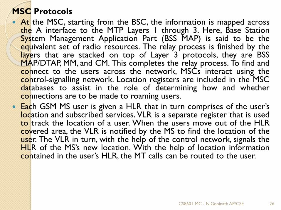
At the MSC, starting from the BSC, the information is mapped acrossthe A interface to the MTP Layers 1 through 3. Here, Base StationSystem Management Application Part (BSS MAP) is said to be theequivalent set of radio resources. The relay process is finished by thelayers that are stacked on top of Layer 3 protocols, they are BSSMAP/DTAP, MM, and CM. This completes the relay process. To find andconnect to the users across the network, MSCs interact using thecontrol-signalling network. Location registers are included in the MSCdatabases to assist in the role of determining how and whetherconnections are to be made to roaming users.
Each GSM MS user is given a HLR that in turn comprises of the user’slocation and subscribed services. VLR is a separate register that is usedto track the location of a user. When the users move out of the HLRcovered area, the VLR is notified by the MS to find the location of theuser. The VLR in turn, with the help of the control network, signals theHLR of the MS’s new location. With the help of location informationcontained in the user’s HLR, the MT calls can be routed to the user.
CS8601 MC - N.Gopinath AP/CSE 26
2.5 GSM Connection Establishment
Localization and Calling:
The fundamental feature of the GSM system is theautomatic, worldwide localization of users for which, thesystem performs periodic location updates.
The HLR always contains information about the currentlocation and the VLR currently responsible for the MSinforms the HLR about the location changes.
Changing VLRs with uninterrupted availability is calledroaming. Roaming can take place within a network of oneprovider, between two providers in a country and alsobetween different providers in different countries.
CS8601 MC - N.Gopinath AP/CSE 27
To locate and address an MS, several numbers are needed:
Mobile station international ISDN number(MSISDN):- This number consists of the countrycode (CC), the national destination code (NDC) and thesubscriber number (SN).
International mobile subscriber identity (IMSI): IMSIconsists of a mobile country code (MCC), the mobilenetwork code (MNC), and finally the mobile subscriberidentification number (MSIN).
Temporary mobile subscriber identity (TMSI): GSMuses the 4 byte TMSI for local subscriber identification.
Mobile station roaming number (MSRN): MSRNcontains the current visitor country code (VCC), thevisitor national destination code (VNDC), theidentification of the current MSC together with thesubscriber number. The MSRN helps the HLR to find asubscriber for an incoming call.
CS8601 MC - N.Gopinath AP/CSE 28
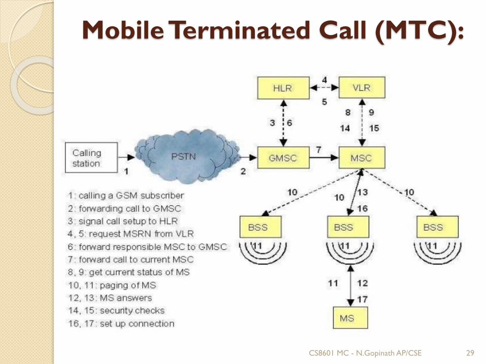
Mobile Terminated Call (MTC):
CS8601 MC - N.Gopinath AP/CSE 29
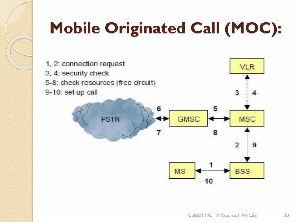
Mobile Originated Call (MOC):
CS8601 MC - N.Gopinath AP/CSE 30
Handover
Cellular systems require handover procedures, assingle cells do not cover the whole service area.
The smaller the cell size and the faster the movementof a mobile station through the cells
The more handovers of ongoing calls are required.
A handover should not cause a cut-off, also called calldrop.
GSM aims at maximum handover duration of 60ms.
2 Basic Reasons for a Handover
1. The mobile station moves out of the range of a BTSof a certain antenna of a BTS respectively.
2. The received signal level decreases continuouslyuntil it alls below the minimal requirements orcommunication.
CS8601 MC - N.Gopinath AP/CSE 31
Types of Handover in GSM 4 Possible Handover Scenarios in GSM
1. Intra-Cell Handover
Narrow band interference could make transmission at a certainfrequency impossible. The BSC could then decide to change thecarrier frequency.
2. Inter-Cell Intra BSC Handover
The mobile station moves from one cell to another, but stays withinthe control of the same BSC. The BSC then performs a handover,assigns a new radio channel in the new cell and releases the oldone .
3. Inter BSC Intra-MSC Handover
BSC controls a limited number of cells; GSM also has to performhandovers between cells controlled by different BSCs. o Thishandover then has to be controlled by the MSC.
4. Inter MSC Handover
A handover could be required between two cells belonging todifferent MSCs. Now both MSCs perform the handover together.
CS8601 MC - N.Gopinath AP/CSE 32
2.6 Frequency Allocation
The most interesting
interface in a GSM system
is Um, the radio interface,
as it comprises various
multiplexing and media
access mechanisms.
GSM implements SDMA
using cells with BTS and
assigns an MS to a BTS.
CS8601 MC - N.Gopinath AP/CSE 33
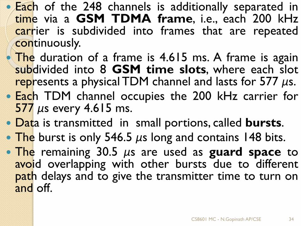
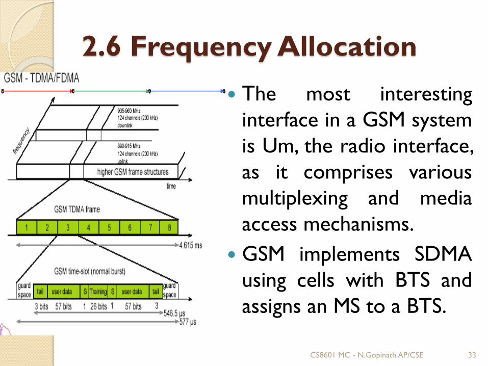
Each of the 248 channels is additionally separated intime via a GSM TDMA frame, i.e., each 200 kHzcarrier is subdivided into frames that are repeatedcontinuously.
The duration of a frame is 4.615 ms. A frame is againsubdivided into 8 GSM time slots, where each slotrepresents a physical TDM channel and lasts for 577 μs.
Each TDM channel occupies the 200 kHz carrier for577 μs every 4.615 ms.
Data is transmitted in small portions, called bursts.
The burst is only 546.5 μs long and contains 148 bits.
The remaining 30.5 μs are used as guard space toavoid overlapping with other bursts due to differentpath delays and to give the transmitter time to turn onand off.
CS8601 MC - N.Gopinath AP/CSE 34
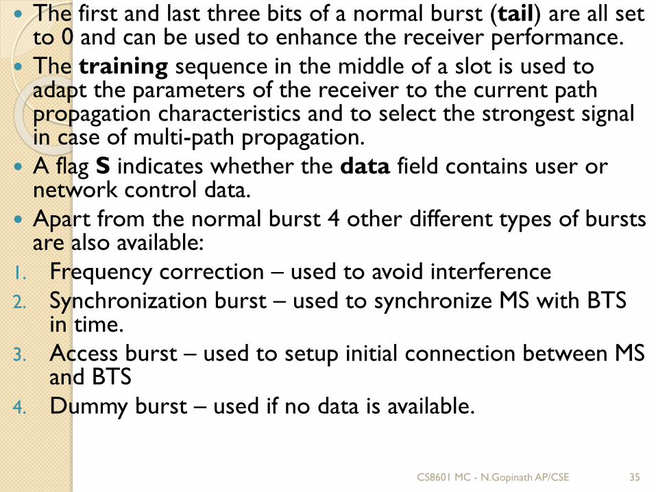
The first and last three bits of a normal burst (tail) are all set to 0 and can be used to enhance the receiver performance.
The training sequence in the middle of a slot is used to adapt the parameters of the receiver to the current path propagation characteristics and to select the strongest signal in case of multi-path propagation.
A flag S indicates whether the data field contains user or network control data.
Apart from the normal burst 4 other different types of bursts are also available:
1. Frequency correction – used to avoid interference
2. Synchronization burst – used to synchronize MS with BTS in time.
3. Access burst – used to setup initial connection between MS and BTS
4. Dummy burst – used if no data is available.
CS8601 MC - N.Gopinath AP/CSE 35
Logical channels and frame hierarchy
Two types of channels, namely physical channelsand logical channels are present.
Physical channel: channel defined by specifyingboth, a carrier frequency and a TDMA timeslotnumber.
Logic channel: logical channels are multiplexedinto the physical channels. Each logic channelperforms a specific task. Consequently the dataof a logical channel is transmitted in thecorresponding timeslots of the physical channel.
CS8601 MC - N.Gopinath AP/CSE 36
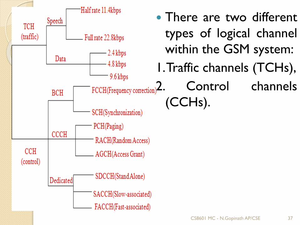
There are two different
types of logical channel
within the GSM system:
1.Traffic channels (TCHs),
2. Control channels
(CCHs).
CS8601 MC - N.Gopinath AP/CSE 37
Traffic Channels: Traffic channels carry userinformation such as encoded speech or userdata. Traffic channels are defined by using a 26-framemultiframe.Two general forms are defined:
Full rate traffic channels (TCH/F), at a gross bit rateof 22.8 kbps (456bits / 20ms)
Half rate traffic channels (TCH/H), at a gross bitrate of 11.4 kbps.
Control Channels: Control channels carry systemsignaling and synchronization data for controlprocedures such as location registration, mobilestation synchronization, paging, random access etc.between base station and mobile station.
Three categories of control channel are defined:Broadcast, Common and Dedicated.
CS8601 MC - N.Gopinath AP/CSE 38
Broadcast control channel (BCCH):A BTS uses this channel to signalinformation to all MSs within a cell. TheBTS sends information for frequencycorrection via the frequencycorrection channel (FCCH) andinformation about time synchronizationvia the synchronization channel(SCH), where both channels are subchannels of the BCCH.
CS8601 MC - N.Gopinath AP/CSE 39
Common control channel (CCCH):
All information regarding connection
setup between MS and BS is exchanged
via the CCCH. For calls toward an MS,
the BTS uses the paging channel
(PCH) for paging the appropriate MS. If
an MS wants to set up a call, it uses the
random access channel (RACH) to
send data to the BTS. The BTS uses the
access grant channel (AGCH) to
signal an MS that it can use a TCH or
SDCCH for further connection setup.
CS8601 MC - N.Gopinath AP/CSE 40
Dedicated control channel (DCCH): Whilethe previous channels have all beenunidirectional, the following channels arebidirectional. , it uses the stand-alonededicated control channel (SDCCH)with a low data rate (782 bit/s) for signalling.Each TCH and SDCCH has a slow associateddedicated control channel (SACCH)associated with it, which is used to exchangesystem information, such as the channel qualityand signal power level. Finally, if more signalinginformation needs to be transmitted and a TCHalready exists, GSM uses a fast associateddedicated control channel (FACCH). TheFACCH uses the time slots which areotherwise used by the TCH.
CS8601 MC - N.Gopinath AP/CSE 41
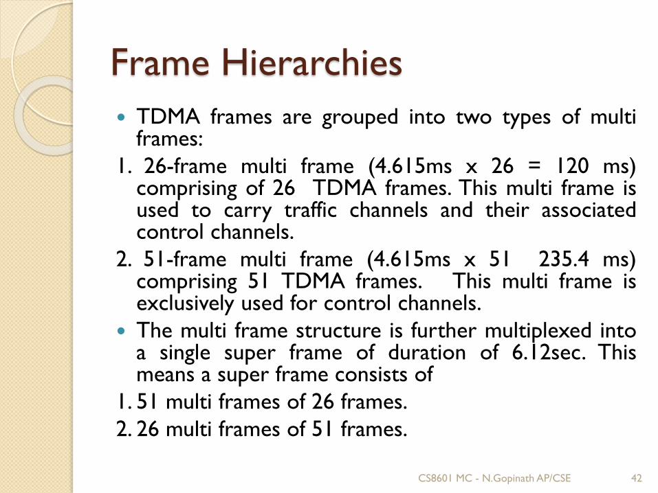
Frame Hierarchies
TDMA frames are grouped into two types of multiframes:
1. 26-frame multi frame (4.615ms x 26 = 120 ms)comprising of 26 TDMA frames. This multi frame isused to carry traffic channels and their associatedcontrol channels.
2. 51-frame multi frame (4.615ms x 51 235.4 ms)comprising 51 TDMA frames. This multi frame isexclusively used for control channels.
The multi frame structure is further multiplexed intoa single super frame of duration of 6.12sec. Thismeans a super frame consists of
1. 51 multi frames of 26 frames.
2. 26 multi frames of 51 frames.
CS8601 MC - N.Gopinath AP/CSE 42
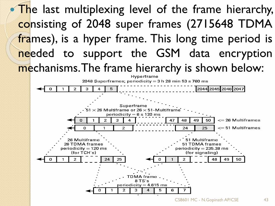
The last multiplexing level of the frame hierarchy,
consisting of 2048 super frames (2715648 TDMA
frames), is a hyper frame. This long time period is
needed to support the GSM data encryption
mechanisms.The frame hierarchy is shown below:
CS8601 MC - N.Gopinath AP/CSE 43
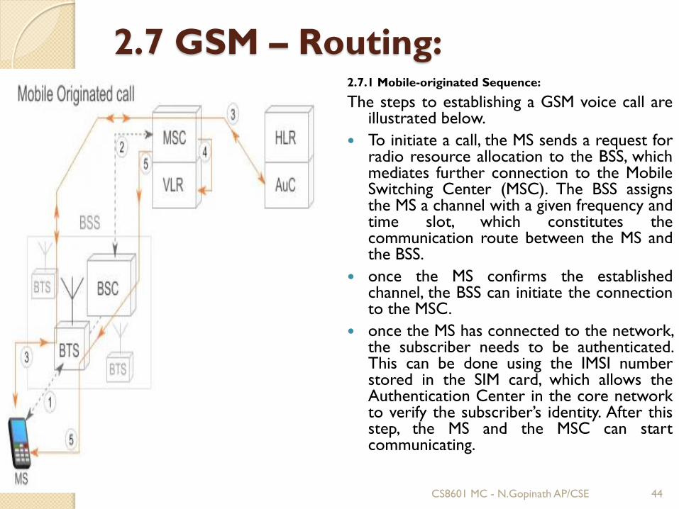
2.7 GSM – Routing:2.7.1 Mobile-originated Sequence:
The steps to establishing a GSM voice call areillustrated below.
To initiate a call, the MS sends a request forradio resource allocation to the BSS, whichmediates further connection to the MobileSwitching Center (MSC). The BSS assignsthe MS a channel with a given frequency andtime slot, which constitutes thecommunication route between the MS andthe BSS.
once the MS confirms the establishedchannel, the BSS can initiate the connectionto the MSC.
once the MS has connected to the network,the subscriber needs to be authenticated.This can be done using the IMSI numberstored in the SIM card, which allows theAuthentication Center in the core networkto verify the subscriber’s identity. After thisstep, the MS and the MSC can startcommunicating.
CS8601 MC - N.Gopinath AP/CSE 44
4. in order to initiate the call setup, the MSC verifies thatthe requested service is allowed for the subscriber. Thisinformation is available in the Virtual Location Register,which maintains temporary subscriber data (location,preferences, allowed services). Once the VLR confirmsthe service requested by the originating MS, the MSCstarts the call setup.
5. for the call to take place, the MSC allocates a voicechannel between the MSC and the BSS. The BSS notifiesthe MS about the change to voice mode, and the MSreturns a confirmation message. The MSC routes thecall to the dialled number. When the call is received inthe PSTN, the MSC is notified that the called subscriberis being alerted, at which point the originating MSreceives a ring notification.
To disconnect the call by either party, a disconnectmessage is sent to the MSC, which releases thecommunication channels created with the PSTN andthe BSS.
CS8601 MC - N.Gopinath AP/CSE 45
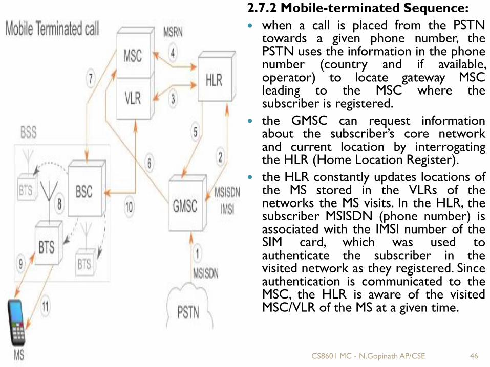
2.7.2 Mobile-terminated Sequence:
when a call is placed from the PSTNtowards a given phone number, thePSTN uses the information in the phonenumber (country and if available,operator) to locate gateway MSCleading to the MSC where thesubscriber is registered.
the GMSC can request informationabout the subscriber’s core networkand current location by interrogatingthe HLR (Home Location Register).
the HLR constantly updates locations ofthe MS stored in the VLRs of thenetworks the MS visits. In the HLR, thesubscriber MSISDN (phone number) isassociated with the IMSI number of theSIM card, which was used toauthenticate the subscriber in thevisited network as they registered. Sinceauthentication is communicated to theMSC, the HLR is aware of the visitedMSC/VLR of the MS at a given time.
CS8601 MC - N.Gopinath AP/CSE 46
In order for the GMSC to pass the call to the MSC, the HLR asks atemporary roaming phone number from the MSC (Mobile StationRoaming Number – MSRN).
the MSRN is sent back from the HLR to the GMSC.
the GMSC forward the call to the MSC using the assigned MSRN.
having received the call, the MSC pages all the BSCs in the area thatit serves.
the BSC, in turn, page the BTSs assigned to them.
the called MS responds to the paging from the BTS, asking toestablish a radio channel to the BTS.
the response is forwarded to the MSC, which, once notified,authenticates the MS and initiates the ciphering of the call using thesame procedure as in MO calls.
when the MSC sends back to the radio network the callconfirmation message, the called MS starts to ring.
At the other end, the MSC notifies the GMSC, which notifies thePSTN that the destination number is being alerted.
CS8601 MC - N.Gopinath AP/CSE 47
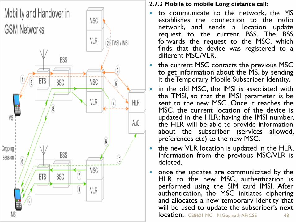
2.7.3 Mobile to mobile Long distance call:
to communicate to the network, the MSestablishes the connection to the radionetwork, and sends a location updaterequest to the current BSS. The BSSforwards the request to the MSC, whichfinds that the device was registered to adifferent MSC/VLR.
the current MSC contacts the previous MSCto get information about the MS, by sendingit the Temporary Mobile Subscriber Identity.
in the old MSC, the IMSI is associated withthe TMSI, so that the IMSI parameter is besent to the new MSC. Once it reaches theMSC, the current location of the device isupdated in the HLR; having the IMSI number,the HLR will be able to provide informationabout the subscriber (services allowed,preferences etc) to the new MSC.
the new VLR location is updated in the HLR.Information from the previous MSC/VLR isdeleted.
once the updates are communicated by theHLR to the new MSC, authentication isperformed using the SIM card IMSI. Afterauthentication, the MSC initiates cipheringand allocates a new temporary identity thatwill be used to update the subscriber’s nextlocation. CS8601 MC - N.Gopinath AP/CSE 48
A handover may also be requested between 2 different MSCs. Thiscase scenario is illustrated in the diagram above in green color.
when the BSC is informed of the location change and finds that thenew location is not in its area, it forwards the handover request tothe MSC, which acknowledges that the subscriber has roamed to adifferent MSC. The MSC has access to the LACs of neighboringMSCs, therefore it can determine the network in which thesubscriber has roamed.
the old MSC sends the request to the target MSC, which asks thecorresponding BSC to establish the speech channel to the MS.
the MS receives handover request via the initially establishedchannel;
communication is moved to the new created channel of the secondMSC. The MSC that initially assigned the MSRN for setting up thecall is called an anchor MSC and is responsible for all the inter-MSChandover procedures that may occur during a call.
in the case of a handover between different MSCs, a newauthentication of the MS will also be performed in the newnetwork.
CS8601 MC - N.Gopinath AP/CSE 49
2.7.4 Mobile in international roaming:
An international transit network allows theexchanging of data between differentoperators, and its services are usuallyregulated by a clearing house, which acts asan intermediary between networks.
It stores usage and call data recordsgenerated in the visited network, that areused for billing in the subscriber’s homenetwork.
This way, an international roaming subscriberis allowed to use the services of the visitednetwork but is charged by the homenetwork.
CS8601 MC - N.Gopinath AP/CSE 50
2.8 Mobility Management:
Mobility management is a functionalitythat facilitates mobile device operations inUniversal Mobile TelecommunicationsSystem (UMTS) or Global System forMobile Communications (GSM)networks.
Mobility management is used to tracephysical user and subscriber locations toprovide mobile phone services, like callsand Short Message Service (SMS).
CS8601 MC - N.Gopinath AP/CSE 51
2.8.1 Location Update Procedure:
A GSM or UMTS network, like all cellularnetworks, is basically a radio network ofindividual cells, known as base stations.
Each base station covers a small geographicalarea which is part of a uniquelyidentified location area.
For GSM, a base station is called a basetransceiver station (BTS), and for UMTS it iscalled a Node B.
A group of base stations is named a locationarea, or a routing area.
CS8601 MC - N.Gopinath AP/CSE 52
The location update procedure allows
a mobile device to inform the cellular
network, whenever it moves from one
location area to the next.
Mobiles are responsible for detecting
location area codes (LAC).
When a mobile finds that the location area
code is different from its last update, it
performs another update by sending to the
network, a location update request, together
with its previous location, and its Temporary
Mobile Subscriber Identity (TMSI).
CS8601 MC - N.Gopinath AP/CSE 53
2.8.2 Temporary Mobile Subscriber
Identity (TMSI):
The Temporary Mobile Subscriber Identity (TMSI) is theidentity that is most commonly sent between the mobile andthe network.
TMSI is randomly assigned by the VLR to every mobile in thearea, the moment it is switched on.
The number is local to a location area, and so it has to beupdated each time the mobile moves to a new geographicalarea.
A key use of the TMSI is in paging a mobile. "Paging" is the one-to-one communication between the mobile and the basestation.
The most important use of broadcast information is to set upchannels for "paging". Every cellular system hasa broadcast mechanism to distribute such information to aplurality of mobiles.
CS8601 MC - N.Gopinath AP/CSE 54
2.8.3 Roaming: Roaming is one of the fundamental mobility
management procedures of all cellular networks.
Roaming is defined as the ability for a cellularcustomer to automatically make and receive voicecalls, send and receive data, or access other services,including home data services, when travelling outsidethe geographical coverage area of thehome network, by means of using a visited network.
This can be done by using a communication terminalor else just by using the subscriber identity in thevisited network.
Roaming is technically supported by a mobilitymanagement, authentication, authorization and billingprocedures.
CS8601 MC - N.Gopinath AP/CSE 55
2.8.4 Types of Area:2.8.4.1. Location Area
A "location area" is a set of base stations that aregrouped together to optimize signalling. Typically, tens oreven hundreds of base stations share a single BaseStation Controller (BSC) in GSM
2.8.4.2. Routing Area
The routing area is the packet-switched domainequivalent of the location area. A "routing area" isnormally a subdivision of a "location area". Routing areasare used by mobiles which are GPRS-attached
2.8.4.3. Tracking Area
The tracking area is the LTE counterpart of the locationarea and routing area. A tracking area is a set of cells.Tracking areas can be grouped into lists of tracking areas(TA lists), which can be configured on the UserEquipment (UE).
CS8601 MC - N.Gopinath AP/CSE 56
2.9 GSM – Security:
GSM offers several security services usingconfidential information stored in the AuCand in the individual SIM.
The SIM stores personal, secret data and isprotected with a PIN against unauthorizeduse.
Three algorithms have been specified toprovide security services in GSM.Algorithm A3 is used for authentication,A5 for encryption, and A8 for thegeneration of a cipher key.
CS8601 MC - N.Gopinath AP/CSE 57
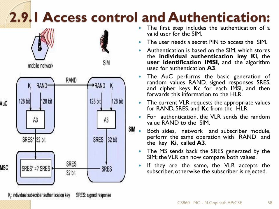
2.9.1 Access control and Authentication: The first step includes the authentication of a
valid user for the SIM.
The user needs a secret PIN to access the SIM.
Authentication is based on the SIM, which storesthe individual authentication key Ki, theuser identification IMSI, and the algorithmused for authentication A3.
The AuC performs the basic generation ofrandom values RAND, signed responses SRES,and cipher keys Kc for each IMSI, and thenforwards this information to the HLR.
The current VLR requests the appropriate valuesfor RAND, SRES, and Kc from the HLR.
For authentication, the VLR sends the randomvalue RAND to the SIM.
Both sides, network and subscriber module,perform the same operation with RAND andthe key Ki, called A3.
The MS sends back the SRES generated by theSIM; theVLR can now compare both values.
If they are the same, the VLR accepts thesubscriber, otherwise the subscriber is rejected.
CS8601 MC - N.Gopinath AP/CSE 58
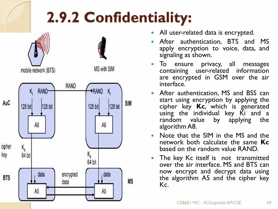
2.9.2 Confidentiality: All user-related data is encrypted.
After authentication, BTS and MSapply encryption to voice, data, andsignaling as shown.
To ensure privacy, all messagescontaining user-related informationare encrypted in GSM over the airinterface.
After authentication, MS and BSS canstart using encryption by applying thecipher key Kc, which is generatedusing the individual key Ki and arandom value by applying thealgorithm A8.
Note that the SIM in the MS and thenetwork both calculate the same Kcbased on the random value RAND.
The key Kc itself is not transmittedover the air interface. MS and BTS cannow encrypt and decrypt data usingthe algorithm A5 and the cipher keyKc.
CS8601 MC - N.Gopinath AP/CSE 59
2.9.3 Anonymity:
To provide user anonymity, all data is
encrypted before transmission, and user
identifiers are not used over the air.
Instead, GSM transmits a temporary
identifier (TMSI), which is newly assigned
by theVLR after each location update.
Additionally, the VLR can change the TMSI
at any time.
CS8601 MC - N.Gopinath AP/CSE 60
2.10 GPRS (General Packet Radio Services):
General packet radio service (GPRS) is a
packet-based wireless data communication
service designed to replace the current
circuit-switched services available on the
second-generation global system for mobile
communications (GSM) and time division
multiple access (TDMA) IS-136 networks.
CS8601 MC - N.Gopinath AP/CSE 61
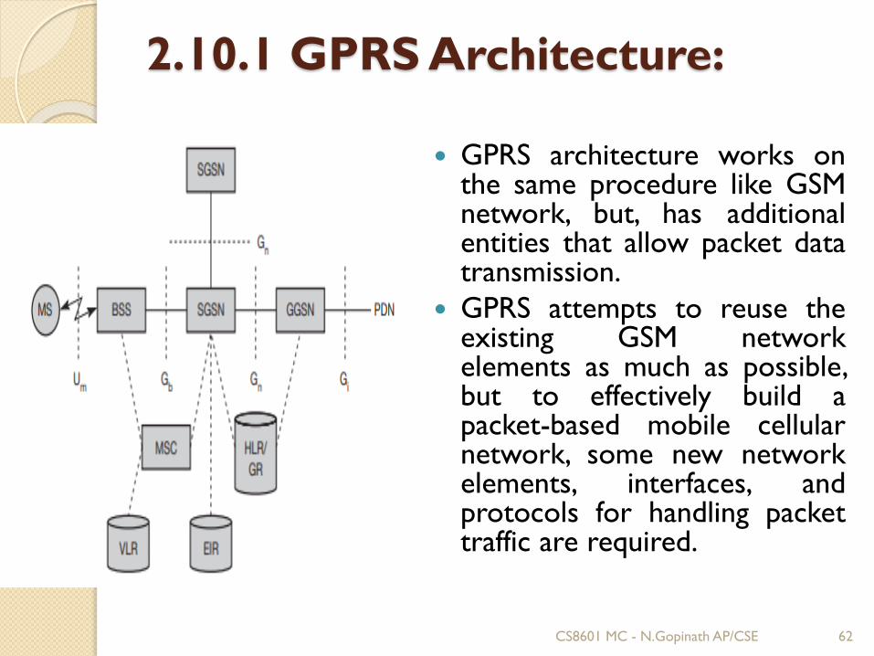
2.10.1 GPRS Architecture:
GPRS architecture works onthe same procedure like GSMnetwork, but, has additionalentities that allow packet datatransmission.
GPRS attempts to reuse theexisting GSM networkelements as much as possible,but to effectively build apacket-based mobile cellularnetwork, some new networkelements, interfaces, andprotocols for handling packettraffic are required.
CS8601 MC - N.Gopinath AP/CSE 62
GPRS Mobile Stations
New Mobile Stations (MS) are required to use GPRSservices because existing GSM phones do not handlethe enhanced air interface or packet data.
A variety of MS can exist, including a high-speedversion of current phones to support high-speed dataaccess.
A new PDA device with an embedded GSM phone,and PC cards for laptop computers.
Base Station Subsystem:
Each BSC requires the installation of Packet ControlUnits in addition to software upgrade.
They provide physical and logical data interface toBSS to estimate packet data traffic.
BTS too require a software upgrade but typicallydoes not involve hardware enhancements.
CS8601 MC - N.Gopinath AP/CSE 63
GRPS Support Nodes:
SSGN: The Serving GPRS Support Node is responsible forauthentication of GPRS mobiles, registration of mobiles in thenetwork, mobility management, and collecting information forcharging for the use of the air interface.
GGSN: The Gateway GPRS Support Node acts as an interfaceand a router to external networks. The GGSN contains routinginformation for GPRS mobiles, which is used to tunnel packetsthrough the IP based internal backbone to the correct ServingGPRS Support Node.
Internal Back Network:
The internal backbone is an IP based network which is used tocarry the new packets between different GSN.
Mobility Support:
In a manner similar to GSM and CDPD, there are mechanism inGPRS to support mobility. There are two types of MobilitySupport in GPRS Network-
Attachment Procedure
Location and Handoff Management
CS8601 MC - N.Gopinath AP/CSE 64
2.10.2 GPRS Services:GPRS extends the GSM Packet circuit switched data capabilitiesand makes the following services possible:
SMS messaging and broadcasting
"Always on" internet access
Multimedia messaging service (MMS)
Push-to-talk over cellular (PoC)
Instant messaging and presence—wireless village
Internet applications for smart devices through wirelessapplication protocol (WAP)
Point-to-point (P2P) service: inter-networking with the Internet(IP)
Point-to-multipoint (P2M) service: point-to-multipoint multicastand point-to-multipoint group calls
If SMS over GPRS is used, an SMS transmission speed of about30 SMS messages per minute may be achieved. This is muchfaster than using the ordinary SMS over GSM, whose SMStransmission speed is about 6 to 10 SMS messages per minute.
CS8601 MC - N.Gopinath AP/CSE 65
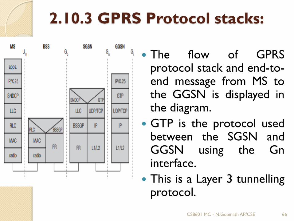
2.10.3 GPRS Protocol stacks:
The flow of GPRSprotocol stack and end-to-end message from MS tothe GGSN is displayed inthe diagram.
GTP is the protocol usedbetween the SGSN andGGSN using the Gninterface.
This is a Layer 3 tunnellingprotocol.
CS8601 MC - N.Gopinath AP/CSE 66
Applications are communicated via standard IP thatGPRS network carries and out through the GPRSgateway.
By using tunnelling protocol, packets are transmittedbetween the GGSN and the SGSN.
GTP runs the UDP and IP.
Sub Network Dependent Convergence Protocol(SNDCP) and Logical Link Control (LLC) combinationused in between the SGSN and the MS communication.
To reduce the load on the radio channel, SNDCPflattens the data.
During mobile, the user moves to a different placewhere new routing area lies under a different SGSN,then old LLC link is no longer used and new link isgenerated with the new Serving GSN X.25. X.25 is usedto provide services on top of TCP/IP in the internalbackbone.
CS8601 MC - N.Gopinath AP/CSE 67
2.11 Universal Mobile Telecommunication Services
(UMTS)
The Universal Mobile TelecommunicationsSystem (UMTS), based on the GSMstandards, is a mobile cellular system ofthird generation that is maintained by3GPP (3rd Generation PartnershipProject).
It specifies a complete network systemand the technology described in it ispopularly referred as Freedom of MobileMultimedia Access (FOMA).
CS8601 MC - N.Gopinath AP/CSE 68
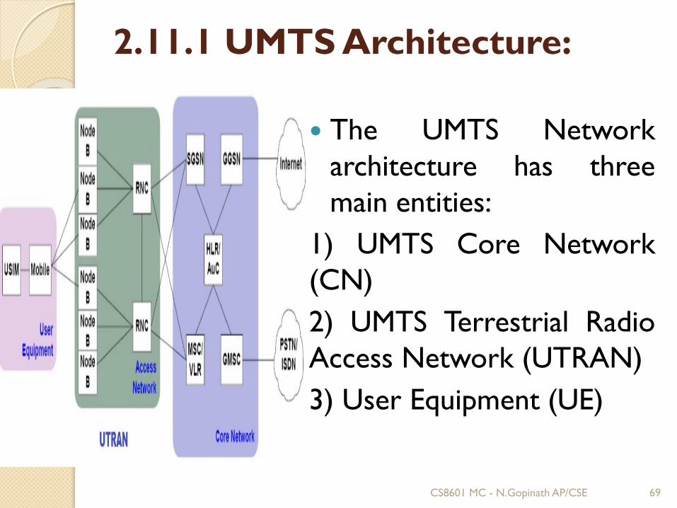
2.11.1 UMTS Architecture:
The UMTS Network
architecture has three
main entities:
1) UMTS Core Network
(CN)
2) UMTS Terrestrial Radio
Access Network (UTRAN)
3) User Equipment (UE)
CS8601 MC - N.Gopinath AP/CSE 69
1) Core Network (CN)
• The UMTS network architecture is partly based on existing 2Gnetwork components and some new 3G network components.
• The CN provides circuit switched (CS) functions as well aspacket switched (PS) functions.
i. 3G-MSC
The 3G-MSC is the main CN element to provide CS services.
The 3G MSC provides the interconnection to externalnetworks like PSTN and ISDN.
ii. 3G-SGSN
The 3G-SGSN is the main CN element for PS services. The3G-SGSN provides the necessary control functionality bothtoward the UE and the 3G-GGSN
iii. 3G-GGSN
The GGSN provides interworking with the external PSnetwork. It is connected with SGSN via an IP-based network.
CS8601 MC - N.Gopinath AP/CSE 70
2) UTRAN:
UMTS terrestrial RAN (UTRAN)
UTRAN consist of Radio Network Subsystems (RNSs). The RNS has twomain elements: Node B and a Radio Network Controllers (RNC).
i) Radio network controller (RNC):
An RNC in UMTS has a broad spectrum of tasks as listed in the following:
1. Call admission control
2. Congestion control
3. Encryption / Decryption
4. ATM switching and Multiplexing, Protocol conversion
5. Radio resource control.
6. Radio Bearer setup and release
7. Code allocation
8. Power control
9. Handover control and RNS relocation.
ii) Node B:
The Node B in UMTS networks provides functions equivalent to the basetransceiver station (BTS) in GSM/GPRS networks.
CS8601 MC - N.Gopinath AP/CSE 71
3) UE:
The UMTS standard does not restrict thefunctionality of the User Equipment in any way.
UMTS mobile station can operate in one of threemodes of operation:
1. PS/CS mode of operation – MS attached to both PSand CS domain
2. PS mode of operation – MS attached to only PSdomain
3. CS mode of operation – MS attached to only CSdomain
UMTS IC card has same physical characteristics asGSM SIM card.
CS8601 MC - N.Gopinath AP/CSE 72
2.11.2 UMTS – Handover:UMTS hard handover
The name hard handover indicates that there is a "hard" change duringthe handover process.
For hard handover the radio links are broken and then re-established.
The basic methodology behind a hard handover is relativelystraightforward.
There are a number of basic stages of a hard handover:
1. The network decides a handover is required dependent upon the signalstrengths of the existing link, and the strengths of broadcast channels ofadjacent cells.
2.The link between the existing Node B and the UE is broken.
3.A new link is established between the new Node B and the UE.
UMTS hard handovers may be used in a number of instances:
1. When moving from one cell to an adjacent cell that may be on adifferent frequency.
2. When implementing a mode change, e.g. from FDD to TDD mode, forexample.
3. When moving from one cell to another where there is no capacity onthe existing channel, and a change to a new frequency is required.
CS8601 MC - N.Gopinath AP/CSE 73
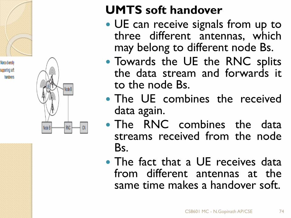
UMTS soft handover
UE can receive signals from up tothree different antennas, whichmay belong to different node Bs.
Towards the UE the RNC splitsthe data stream and forwards itto the node Bs.
The UE combines the receiveddata again.
The RNC combines the datastreams received from the nodeBs.
The fact that a UE receives datafrom different antennas at thesame time makes a handover soft.
CS8601 MC - N.Gopinath AP/CSE 74
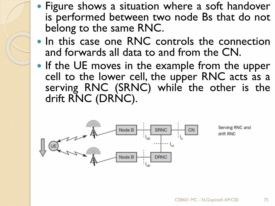
Figure shows a situation where a soft handoveris performed between two node Bs that do notbelong to the same RNC.
In this case one RNC controls the connectionand forwards all data to and from the CN.
If the UE moves in the example from the uppercell to the lower cell, the upper RNC acts as aserving RNC (SRNC) while the other is thedrift RNC (DRNC).
CS8601 MC - N.Gopinath AP/CSE 75
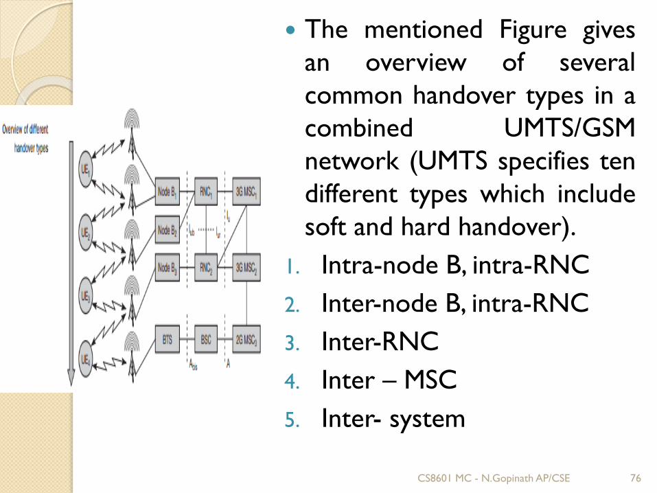
The mentioned Figure gives
an overview of several
common handover types in a
combined UMTS/GSM
network (UMTS specifies ten
different types which include
soft and hard handover).
1. Intra-node B, intra-RNC
2. Inter-node B, intra-RNC
3. Inter-RNC
4. Inter – MSC
5. Inter- system
CS8601 MC - N.Gopinath AP/CSE 76
2.11.3 UMTS – Security:The main security elements that are from GSM:
Authentication of subscribers
Subscriber identity confidentially
Subscriber Identity Module (SIM) to be removable fromterminal hardware
Radio interface encryption
Additional UMTS security features:
Security against using false base stations with mutualauthentication
Encryption extended from air interface only to includeNode-B to RNC connection
Security data in the network will be protected in datastorages and while transmitting ciphering keys andauthentication data in the system.
Mechanism for upgrading security features.
CS8601 MC - N.Gopinath AP/CSE 77
UMTS specification has five security featuregroups:
Network access security
Network domain security
User domain security
Application domain security
UMTS specification has the following useridentity confidentiality security features:
User identity confidentiality
User location confidentiality
User intractability
CS8601 MC - N.Gopinath AP/CSE 78