Embed Size (px)
Citation preview

ME1201-ENGINEERING THERMODYNAMICS
S.K.AYYAPPAN, Lecturer, Department of mechanical engineering
UNIT II
SECOND LAW
Second law of thermodynamics – Kelvin’s and Clausius statements of
second law – Reversibility and irreversibility – Carnot theorem – Carnot
cycle – Reversed carnot cycle – efficiency – COP –Thermodynamic
temperature scale – Clausius inequality – concept of entropy – entropy of
ideal gas –principle of increase of entropy – availability.

ME1201-ENGINEERING THERMODYNAMICS
S.K.AYYAPPAN, Lecturer, Department of mechanical engineering
Second Law
One form of energy can be converted into other form and any process is possible as long as it
does not create energy or destroy energy. Also, in a cyclic process, heat is converted in to
work and vice-versa.
But in actual practice, all forms of energy cannot be changed into work.
Let there be two thermodynamic system X and Y at temperature T1 and T2 respectively such
that T1›T2
T1›T2 T‹T1 T›T1
SECOND LAW OF THERMODYNAMICS:
i) Kelvin-planck statement and
ii) Clausius statement
Kelvin-Planck statement:
It is impossible to construct an operating device working on a cyclic process which
produces other effect than the extraction of energy as heat from a single thermal
reservoir and performs an equivalent amount of work.
Qs Qs
W=Qs- QR
W=Qs-QR
QR
Impossible heat engine by II law
Possible heat engine by II law
Otherwise, it is impossible to construct an engine working on a cyclic process which converts
all the heat energy supplied into equivalent amount of useful work.
Simply, we can say that all the heat energy given to an engine cannot be converted it into
useful work and some amount of heat energy will rejected to sink.
Clausius statement:
SYSTEM X
T1
SYSTEM Y
T2
SYSTEM
X
T
SYSTEM Y
T
RESERVOIR
HEAT
ENGINEE
Hot Reservoir
Cold reservoir
HEAT ENGINE

ME1201-ENGINEERING THERMODYNAMICS
S.K.AYYAPPAN, Lecturer, Department of mechanical engineering
It is impossible to construct an operating device working on a cyclic process which produces
no other effect than the transfer of energy as heat from a low temperature body to a high
temperature body.
Otherwise, it may be stated as “heat cannot flow from cold reservoir to hot reservoir without
any external aid. But, heat can flow from hot reservoir to cold reservoir without any external
aid”
Q
Impossible system possible system
Clausious statement
Reversibility:
All the processes are divided into two types based on second law of thermodynamics.
1. Reversible process or ideal process
2. Irreversible process or actual process or natural process.
A
P B
V
A process is performed in such a way that it should trace the same path when the process is
reversed known as reversible process. It means it does not follow the different path without
producing any change in the universe when it is reversed.
Process taken from A to B. by a path A-B. Similarly, when the same process is reversed, it
attains the initial state by a path in the same manner as that of the process already carried out.
The work involved due to this process is known as reversible work or maximum work or
ideal work. A quasi-static process is also a reversible process.
Irreversibility:
Hot reservoir
Cold reservoir
Hot reservoir
Cold reservoir
Heat engine

ME1201-ENGINEERING THERMODYNAMICS
S.K.AYYAPPAN, Lecturer, Department of mechanical engineering
All the processes are irreversible process. When any process is reversed, it definitely should
not the same path as the original process. At the same time, it produces a change in the
universe. So, the path traced by the reversal process is different. Therefore, the work involved
due to this process is called as irreversible work. Irreversibility is produced due to various
reasons.
Causes:
1. Lack of equilibrium
2. Heat transfer through a finite temperature difference
3. Lack of pressure equilibrium within the interior of the system.
4. Free expansion
5. Dissipative effects
Qualitative difference between heat and work:
The energy gained by one would be exactly equal to that lost by the other. It is the second law
of thermodynamics which provides the criterion as the probability of various processes.
When supplied to a system in the form of work, can be completely converted into heat (work
transfer internal energy increase heat transfer).
But the complete conversion of heat into work in a cycle is not possible. So heat and work are
not completely interchangeable forms of energy.
When work is converted into heat, we always have
W = Q
When heat is converted into work in a complete closed cycle process
Q ≥W
The arrow indicates the direction of energy transformation. A system is taken from state 1 to
state 2 by work transfer W1-2, and then by heat transfer Q2-1 the system is brought back
from state 2 to state1 to complete a cycle.
W1-2=Q2-1
Work is said to be high grade energy and heat low grade energy. The complete conversion of
low grade energy into high grade energy in a cycle is impossible.
Cyclic heat engine:
A heat engine cycle is a thermodynamic cycle in which there is a net heat transfer to the
system and a net work transfer from the system. The system which executes a heat engine
cycle is called a heat engine.
The net heat transfer in a cycle to either of the heat engines
Qnet=Q1-Q2
And the net work transfer in a cycle
Wnet=WT-WP
(Or)
Wnet=WE-WC
By the first law of thermodynamics, we have
∑cycleQ=∑cycleW
Qnet=Wnet

ME1201-ENGINEERING THERMODYNAMICS
S.K.AYYAPPAN, Lecturer, Department of mechanical engineering
Q1-Q2=WT-WP
η= net work output of the cycle/ total heat input to the cycle
=Wnet/Q1
η=Wnet/Q1=WT-Wp/Q1=Q1-Q2/Q1
η=1-Q2/Q1
This is also known as the thermal energy of heat engine cycle.
A heat engine is very often called upon to extract as much work (net) as possible from a
certain heat input, i.e., to maximize the cycle efficiency.
Heat engine:
Heat engine is a device which operates in a thermodynamics cycle and produces work by
supplying heat from hot reservoir.
Qs
W
η=W/Qs
W=Qs-QR
η=Qs-QR/QS=TH-TL/TH
=1-QR/QS=1-TL/TH
Energy reservoirs:
A thermal energy reservoir (TER) is defined as a large body of infinite heat capacity, which
is capable of absorbing or rejecting an unlimited quantity of heat without suffering
appreciable changes in its thermodynamic coordinates.
The thermal energy reservoir TERH from which heat Q1 is transferred to the system operating
in a heat engine cycle is called the source.
The energy reservoir TERL to which heat Q2 is rejected from the system during a cycle is the
sink.
A mechanical energy reservoir (MER) is a large body enclosed by an adiabatic impermeable
wall capable of storing work as potential energy or kinetic energy.
Q1
Wp WT
Wnet
CHE
Q2
TERH (source)
B
P T C
TERL (sink)
MER
Hot temperature reservoir,TH
Low temperature reservoir, TL
Heat engine
QR

ME1201-ENGINEERING THERMODYNAMICS
S.K.AYYAPPAN, Lecturer, Department of mechanical engineering
Cyclic heat engine (CHE) with source and sink.
Refrigerator:
Refrigerator is a device which is used to remove heat from a cold system. In other words, it is
used to maintain the temperature of the body lower than that of surroundings.
Qs
Refrigerator
W
Performance of a refrigerator or a heat pump is measured with a term called coefficient of
performance. It is the ratio of heat extracted to the work input.
COP of a refrigerator is given by
(C.O.P) ref= QR/W=QR/QS-QR=TL/TH-TL
Where, TH and TL are higher lower temperature respectively.
Heat pump:
Heat pump is a device which is used to supply heat to a hotter system. In other words, it is
used to maintain the temperature of the body higher than the surroundings.
Qs
W
(C.O.P)HP=QS/W=QS/QS-QL=TH/TH-TL
Hot temperature reservoir,TH (atm)
Low temperature reservoir, TL
Ref
QR
Hot temperature reservoir,TH
Low temperature reservoir, TL(Atm)
HP
QR
ME1201-ENGINEERING THERMODYNAMICS
S.K.AYYAPPAN, Lecturer, Department of mechanical engineering
Where, TH and TL are higher lower temperature respectively.
Corollaries of the second law of thermodynamics:
The statements which can be proved with the help of reversible cycles are called as
corollaries of the second law of thermodynamics.
Corollary-1
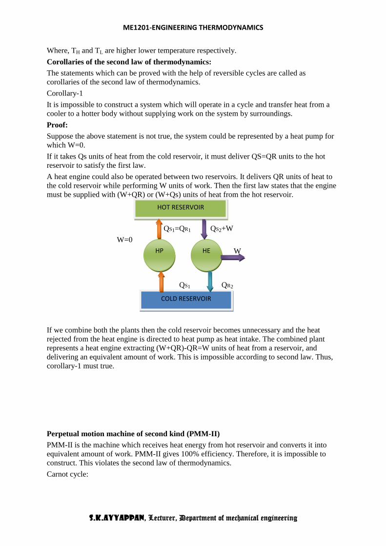
It is impossible to construct a system which will operate in a cycle and transfer heat from a
cooler to a hotter body without supplying work on the system by surroundings.
Proof:
Suppose the above statement is not true, the system could be represented by a heat pump for
which W=0.
If it takes Qs units of heat from the cold reservoir, it must deliver QS=QR units to the hot
reservoir to satisfy the first law.
A heat engine could also be operated between two reservoirs. It delivers QR units of heat to
the cold reservoir while performing W units of work. Then the first law states that the engine
must be supplied with (W+QR) or (W+Qs) units of heat from the hot reservoir.
QS1=QR1 QS2+W
W=0
W
QS1 QR2
If we combine both the plants then the cold reservoir becomes unnecessary and the heat
rejected from the heat engine is directed to heat pump as heat intake. The combined plant
represents a heat engine extracting (W+QR)-QR=W units of heat from a reservoir, and
delivering an equivalent amount of work. This is impossible according to second law. Thus,
corollary-1 must true.
Perpetual motion machine of second kind (PMM-II)
PMM-II is the machine which receives heat energy from hot reservoir and converts it into
equivalent amount of work. PMM-II gives 100% efficiency. Therefore, it is impossible to
construct. This violates the second law of thermodynamics.
Carnot cycle:
HOT RESERVOIR
COLD RESERVOIR
HP HE
ME1201-ENGINEERING THERMODYNAMICS
S.K.AYYAPPAN, Lecturer, Department of mechanical engineering
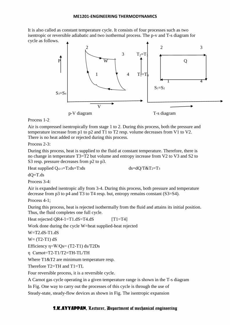
It is also called as constant temperature cycle. It consists of four processes such as two
isentropic or reversible adiabatic and two isothermal process. The p-v and T-s diagram for
cycle as follows.
2 2 3
3 T2=T3
P W Q
1 4 T1=T4
1 4
S1=S2
S3=S4
V
p-V diagram T-s diagram
Process 1-2
Air is compressed isentropically from stage 1 to 2. During this process, both the pressure and
temperature increase from p1 to p2 and T1 to T2 resp. volume decreases from V1 to V2.
There is no heat added or rejected during this process.
Process 2-3:
During this process, heat is supplied to the fluid at constant temperature. Therefore, there is
no change in temperature T3=T2 but volume and entropy increase from V2 to V3 and S2 to
S3 resp. pressure decreases from p2 to p3.
Heat supplied Qs2-3=T2ds=T3ds ds=dQ/T&T2=T3
dQ=T.ds
Process 3-4:
Air is expanded isentropic ally from 3-4. During this process, both pressure and temperature
decrease from p3 to p4 and T3 to T4 resp. but, entropy remains constant (S3=S4).
Process 4-1;
During this process, heat is rejected isothermally from the fluid and attains its initial position.
Thus, the fluid completes one full cycle.
Heat rejected QR4-1=T1.dS=T4.dS [T1=T4]
Work done during the cycle W=heat supplied-heat rejected
W=T2.dS-T1.dS
W= (T2-T1) dS
Efficiency η=W/Qs= (T2-T1) ds/T2Ds
η Carnot=T2-T1/T2=TH-TL/TH
Where T1&T2 are minimum temperature resp.
Therefore T2=TH and T1=TL
Four reversible process, it is a reversible cycle.
A Carnot gas cycle operating in a given temperature range is shown in the T-s diagram
In Fig. One way to carry out the processes of this cycle is through the use of
Steady-state, steady-flow devices as shown in Fig. The isentropic expansion

ME1201-ENGINEERING THERMODYNAMICS
S.K.AYYAPPAN, Lecturer, Department of mechanical engineering
process 2-3 and the isentropic compression process 4-1 can be simulated quite well by
A well-designed turbine and compressor respectively, but the isothermal expansion
process 1-2 and the isothermal compression process 3-4 are most difficult to achieve.
Because of these difficulties, a steady-flow Carnot gas cycle is not practical.
The Carnot gas cycle could also be achieved in a cylinder-piston apparatus (a
reciprocating engine) as shown in Fig. The Carnot cycle on the p-v diagram is as
shown in Fig, in which processes 1-2 and 3-4 are isothermal while processes 2-3
and 4-1 are isentropic. We know that the Carnot cycle efficiency is given by the
expression.

ME1201-ENGINEERING THERMODYNAMICS
S.K.AYYAPPAN, Lecturer, Department of mechanical engineering

ME1201-ENGINEERING THERMODYNAMICS
S.K.AYYAPPAN, Lecturer, Department of mechanical engineering
Reversed Carnot Cycle:
Reversed Carnot cycle is shown in Fig.. It consists of the following processes.
Process a-b: Absorption of heat by the working fluid from refrigerator at constant low
temperature T2 during isothermal expansion.
Process b-c: Isentropic compression of the working fluid with the aid of external work.
The temperature of the fluid rises from T2 to T1.

ME1201-ENGINEERING THERMODYNAMICS
S.K.AYYAPPAN, Lecturer, Department of mechanical engineering
Process c-d: Isothermal compression of the working fluid during which heat is rejected
at constant high temperature T1.
Process d-a: Isentropic expansion of the working fluid. The temperature of the working
fluid falls from T1 to T2.
Practically, the reversed Carnot cycle cannot be used for refrigeration purpose as the
isentropic process requires very high speed operation, whereas the isothermal process
requires very low speed operation.
Thermodynamic Temperature Scale
To define a temperature scale that does not depend on the thermometric property of a
substance, Carnot principle can be used since the Carnot engine efficiency does not depend
on the working fluid. It depends on the temperatures of the reservoirs between which it
operates.

ME1201-ENGINEERING THERMODYNAMICS
S.K.AYYAPPAN, Lecturer, Department of mechanical engineering
Consider the operation of three reversible engines 1, 2 and 3. The engine 1 absorbs energy Q1
as heat from the reservoir at T1, does work W1 and rejects energy Q2 as heat to the reservoir
at T2.
Let the engine 2 absorb energy Q2 as heat from the reservoir at T2 and does work W2 and
rejects energy Q3 as heat to the reservoir at T3.
The third reversible engine 3, absorbs energy Q1as heat from the reservoir at T1, does work
W3 and rejects energy Q3 as heat to the reservoir at T3.
1 = W1 / Q1 = 1- Q2/Q1 = f(T1,T2)
or, Q1/Q2 = F(T1,T2)
2 = 1- Q3/Q2 = f(T2,T3)
or, T2/T3 = F(T2,T3)
3 = 1- Q3/Q1 = f(T1,T3)
T1/T3 = F(T1,T3)
Then , Q1/Q2 = (Q1/Q3)/(Q2/Q3)
Or, F(T1,T2) = F(T1,T3) /F(T2,T3)
Since T3 does not appear on the left side, on the RHS also T3 should cancel out. This is
possible if the function F can be written as
F(T1, T2) = (T1) (T2)
(T1) (T2) = { (T1) (T3)} / { (T2) (T3)}
= (T1) (T2)

ME1201-ENGINEERING THERMODYNAMICS
S.K.AYYAPPAN, Lecturer, Department of mechanical engineering
Therefore, (T2) = 1 / (T2)
Hence, Q1 / Q2 = F(T1,T2) = (T1)/ (T2)
Now, there are several functional relations that will satisfy this equation. For the
thermodynamic scale of temperature, Kelvin selected the relation
Q1/Q2 = T1/T2
That is, the ratio of energy absorbed to the energy rejected as heat by a reversible engine is
equal to the ratio of the temperatures of the source and the sink.
The equation can be used to determine the temperature of any reservoir by operating a
reversible engine between that reservoir and another easily reproducible reservoir and by
measuring efficiency (heat interactions). The temperature of easily reproducible thermal
reservoir can be arbitrarily assigned a numerical value (the reproducible reservoir can be at
triple point of water and the temperature value assigned 273.16 K).
The efficiency of a Carnot engine operating between two thermal reservoirs the temperatures
of which are measured on the thermodynamic temperature scale, is given by
1 = 1- Q2/Q1 = 1 – T2/T1
The efficiency of a Carnot engine, using an ideal gas as the working medium and the
temperature measured on the ideal gas temperature scale is also given by a similar
expression.
(COP)R = QL /(QH – QL) = TL / (TH – TL)
(COP)HP= QH /(QH – QL) = TH / (TH – TL)
The Carnot cycle uses only two thermal reservoirs – one at high temperature T1 and the other
at two temperature T2.

ME1201-ENGINEERING THERMODYNAMICS
S.K.AYYAPPAN, Lecturer, Department of mechanical engineering
If the process undergone by the working fluid during the cycle is to be reversible, the heat
transfer must take place with no temperature difference, i.e. it should be isothermal.
The Carnot cycle consists of a reversible isothermal expansion from state 1 to 2, reversible
adiabatic expansion from state 2 to 3, a reversible isothermal compression from state 3 to 4
followed by a reversible adiabatic compression to state 1.
The thermal efficiency, is given by
= Net work done / Energy absorbed as heat
During processes 2-3 and 4-1, there is no heat interaction as they are adiabatic.
)/ln( 121
2
1
1
2
1
21 vvRTv
dvRTPdvQ
Similarly for the process 3-4,
)/ln( 342
4
3
2
4
3
43 vvRTv
dvRTPdvQ
Net heat interaction = Net work done
= RT1ln(v2/v1) + RT2ln(v4/v3)
= RT1ln(v2/v1) - RT2ln(v3/v4)
The processes 2-3 and 4-1 are reversible, adiabatic and hence
T1v2-1
= T2v3-1
Or, v2/v3 = (T2/T1)1/( -1)
And T2v4-1
= T1v1-1
Or, v1/v4 = (T2/T1)1/( -1)
v2/v3 = v1/v4 or v2/v1 = v3/v4
= {RT1ln(v2/v1) - RT2ln(v3/v4)} / RT1ln(v2/v1)
= (T1 – T2)/T1
= 1- T2/T1
The Carnot Principles
1. The efficiency of an irreversible heat engine is always less than the efficiency of a
reversible one operating between same two thermal reservoirs.

ME1201-ENGINEERING THERMODYNAMICS
S.K.AYYAPPAN, Lecturer, Department of mechanical engineering
2. The efficiencies of all reversible heat engines operating between the same two
thermal reservoirs are the same.
Lets us assume it is possible for an engine I to have an efficiency greater than the efficiency
of a reversible heat engine R.
I > R
Let both the engines absorb same quantity of energy Q1. Let Q and Q2 represent the energy
rejected as heat by the engines R, and I respectively.
WI = Q1 - Q
WR= Q1 – Q2
I = WI / Q1 = (Q1 - Q)/Q1 = 1-Q/Q1
R = WR/Q1 = (Q1 - Q2)/Q1 = 1-Q2/Q1
Since I > R,
1-Q/Q1 > 1-Q2/Q1
or, Q < Q2

ME1201-ENGINEERING THERMODYNAMICS
S.K.AYYAPPAN, Lecturer, Department of mechanical engineering
Therefore, WI (= Q1-Q) > WR (=Q1 – Q2)
Since the engine R is reversible, it can be made to execute in the reverse order. Then, it will
absorb energy Q2 from the reservoir at T2 and reject energy Q1 to the reservoir at T1 when
work WR is done on it.
If now engines I and R are combined, the net work delivered by the combined device is given
by
WI – WR = Q1 – Q – (Q1 – Q2) = Q2 – Q
The combined device absorbs energy (Q2 – Q) as heat from a single thermal reservoir and
delivers an equivalent amount of work, which violates the second law of thermodynamics.
Hence, R I
Carnot principle 2
Consider two reversible heat engines R1 and R2 , operating between the two given thermal
reservoirs at temperatures T1 and T2.
Let R1 > R2
Q1= energy absorbed as heat from the reservoir at T1 by the engines R1 and R2, separately.
Q = energy rejected by reversible engine R1 to the reservoir at T2
Q2 = energy rejected by reversible engine R2 to the reservoir at T2.
WR1 = Q1 - Q = work done by a reversible engine R1 .
WR2 = Q1 –Q2 = work done by a reversible engine R2
According to assumption, R1 > R2 Or, 1 – Q/Q1 > 1- Q2/Q1
Q1 –Q >Q1-Q2 or WR1 >WR2
WR1 – WR2 = (Q1 –Q) – (Q1- Q2) = Q2 – Q
Since the engine R2 is reversible, it can be made to execute the cycle in the reverse by
supplying WR2.

ME1201-ENGINEERING THERMODYNAMICS
S.K.AYYAPPAN, Lecturer, Department of mechanical engineering
Since WR1 > WR2 the reversible engine R2 can be run as a heat pump by utilizing part of the
work delivered by R1. For the combined device,
WR1 – WR2 = Q2 – Q, by absorbing energy Q2 – Q from a single thermal reservoir which
violates the second law of thermodynamics.
Hence R1 > R2 is incorrect.
By similar arguments, if we assume that R2 > R1 then,
R1 R2
Therefore, based on these two equations,
R1 = R2
The efficiency of a reversible heat engine is also independent of the working fluid and
depends only on the temperatures of the reservoirs between which it operates.
Carnot theorem:
It states that all of the heat engines operating between a given constant temperature source
and a given constant temperature sink, none has a higher efficiency than a reversible.
(or)
“no heat engine operating in a cycle process between two fixed temperatures can be more
efficient than a reversible engine while operating between the same temperatures limit”Let
two heat engines EA and EB operate between the given source at temperature t1 and the
given sink at temperature t2 as shown in fig.
Source t1
Q1A Q1B
WA WB
Let EA be any heat engine and EB be any reversible heat engine. We have to prove that the
efficiency of EB is more than that of EA. Let us assume that this is not true and ηA>ηB
Q1A=Q1B=Q1
ηA>ηB
WA/Q1A>WB/Q1B
WA>WB
Let EB be reversed. Since EB is a reversible heat engine, the magnitude of heat and work
transfer quantities will remain the same, but their directions will be reversed. Since WA>WB
Some part of WA (Equal to WB ) may be fed to drive the reversed heat engine B. Since
Q1A=Q1B=Q1, the heat discharged by B may be supplied to A. the source may, therefore,
EA EB
Q2B Q2A
Sink t2
Two cyclic heat engines EA and EB operating between the same source and sink, of which EB is reversible.

ME1201-ENGINEERING THERMODYNAMICS
S.K.AYYAPPAN, Lecturer, Department of mechanical engineering
be eliminated. The net result is that A and B together constitute a heat engine which,
operating in a cycle, produces a net work WA-WB, while exchanging heat with a single
reservoir at t2. This violates the Kelvin-planck statement of the second law. Hence the
assumption that ηA>ηB is wrong.
Therefore ηB≥ηA.
Corollaries of Carnot theorem:
Corollary I
All reversible engines operating between the two given temperature limits have the efficiency
Corollary II
Efficiency of all the reversible engine depends only on the temperature limit of the reservoirs
and is independent of the nature of working fluid.
Clausius Inequality
For a Carnot cycle
Q1/Q2=T1/T2
Or Q1/T1-Q2/T2=0 for a reversible engine.
With the usual sign convention, that is, heat flow into a system taken as positive and heat
outflow of the system taken as negative
Q1/T1+Q2/T2=0 or Qi/Ti=0
For an irreversible engine absorbing Q1 amount of heat from a reservoir at T1 and rejecting
Q21 to a reservoir at T2, then
1-Q21/Q1 1-Q2/Q1
or 1-Q21/Q1 1-T2/T1
or Q21/Q1 T2/T1
or Q21/T2 Q1/T1
making use of the sign convention, we get
Q21/T2+Q1/T1 0
Or Q/T 0 for an irreversible engine

ME1201-ENGINEERING THERMODYNAMICS
S.K.AYYAPPAN, Lecturer, Department of mechanical engineering
Replacement of a Reversible process by an equivalent process
Let us consider cyclic changes in a system other than heat engines. If the cycle can be split up
into a large number of heat engine cycles then the above observation can be made use of in
relating the heat interactions with the absolute temperatures.
Any reversible process can be approximated by a series of reversible, isothermal and
reversible, adiabatic processes.
Consider a reversible process 1-2. The same change of a state can be achieved by process 1-a
(reversible adiabatic process), isothermal process a-b-c and a reversible adiabatic process c-2.
The areas 1-a-b and b-c-2 are equal. From the first law
U2-U1=Q1-a-b-c-2-W1-a-b-c-2
Consider the cycle 1-a-b-c-2-b-1. The net work of the cycle is zero. Then
01221 bcba WWdW
or
211221 bbcba WWW
The heat interaction along the path 1-a-b-c-2 is
Q1-a-b-c-2=Q1-a+Qa-b-c+Qc-2=Qa-b-c

ME1201-ENGINEERING THERMODYNAMICS
S.K.AYYAPPAN, Lecturer, Department of mechanical engineering
Since 1-a and c-2 are reversible adiabatic paths. Hence
U2-U1=Qa-b-c-W1-b-2
Application of the first law of the thermodynamics to the process 1-b-2 gives
U2-U1=Q1-b-2-W1-b-2
Comparing the two equations
Qa-b-c=Q1-b-2
The heat interaction along the reversible path 1-b-2 is equal to that along the isothermal path
a-b-c. Therefore a reversible process can be replaced by a series of reversible adiabatic and
reversible isothermal processes.
Clausius Inequality
A given cycle may be subdivided by drawing a family of reversible, adiabatic lines. Every
two adjacent adiabatic lines may be joined by two reversible isotherms.
The heat interaction along the reversible path is equal to the heat interaction along the
reversible isothermal path.
The work interaction along the reversible path is equal to the work interaction along the
reversible adiabatic and the reversible isothermal path.
That is,

ME1201-ENGINEERING THERMODYNAMICS
S.K.AYYAPPAN, Lecturer, Department of mechanical engineering
Qa-b=Qa1-b1 and Qc-d=Qc1-d1
a1-b1-d1-c1 is a Carnot cycle.
The original reversible cycle thus is a split into a family of Carnot cycles. For every Carnot
cycle
0/TdQ . Therefore for the given reversible cycle,
0/TdQ
If the original cycle is irreversible
0/TdQ
so the generalized observation is
0/TdQ
Whenever a system undergoes a cyclic change, however complex the cycle may be( as long
as it involves heat and work interactions), the algebraic sum of all the heat interactions
divided by the absolute temperature at which heat interactions are taking place considered
over the entire cycle is less than or equal to zero (for a reversible cycle).
Clausius inequality:
Clausius inequality states that “when a system undergoes a cyclic process, the summation of
dQ/T around a closed cycle is less than or equal to zero
Consider an engine operating between two fixed temperature reservoirs TH and TL. Let dQs,
units of heat be supplied at temperature TH and dQR units of heat be rejected at temperature
TL during a cycle.
Thermal efficiency,η=dQs-dQR/dQs
Thermal efficiency of any reversible engine working on the same temperature limit is given
by
Thermal efficiency for reversible engine=TH-TL/TH
The efficiency of an actual engine cycle must be less than that of a reversible cycle.
Since no engine can be more efficient than that of a reversible engine
dQs-dQR/dQs≤TH-TL/TH
dQR/dQs≤ TL/TH
dQR/TL≤ dQs/TH
dQR/TL- dQs/TH ≤0
entire cycle ∫ dQ/T≤0
ME1201-ENGINEERING THERMODYNAMICS
S.K.AYYAPPAN, Lecturer, Department of mechanical engineering
this equation is known as clausius inequality. It provides the criterion of the reversibility of a
cycle.
If ∫ dQ/T=0, The cycle is revesible.
If ∫ dQ/T<0, the cycle is irrerversible and possible.
If ∫ dQ/T>0, the cycle is impossible.
Since the cyclic integral ∫ dQ/T<0, the cycle violates the second law of thermodynamics. So,
it is impossible
∫ dQ/T=0,
Concept of entropy:
Entropy is an index of unavailability or degradation of energy. Heat always flow from hot
body to cold body and thus become lesser value available. This unavailability of energy is
measured by entropy. It is an important thermodynamics property of the working substance.
It increases with the addition of heat and decreases with its removal. It is the function of
quantity of heat with respect to temperature.
We are usually interested in change in entropy. The change in entropy for reversible process
is mathematically given by
Change in entropy, dS= change of heat transfer/absolute temperature=( dQ/T)
Unit of entropy is kj/K or j/K
For reversible adiabatic process change in entropy is zero.
Entropy
1. T
dQ has the same value irrespective of path as long as path is reversible
2. RT
dQ is an exact differential of some function which is identical as entropy
3. 2
1
2
1
12RT
dQdSSSS
4. RT
dQdS for reversible process only
Calculation of Entropy change
1. Entropy is a state function. The entropy change is determined by its initial and final
states only
2. In analyzing irreversible process, it is not necessary to make a direct analysis of
actual reversible process.

ME1201-ENGINEERING THERMODYNAMICS
S.K.AYYAPPAN, Lecturer, Department of mechanical engineering
Substitute actual process by an imaginary reversible process. The entropy change for
imaginary reversible process is same as that of an irreversible process between given
final and initial states.
(a) Absorption of energy by a constant temperature reservoir
Energy can be added reversibly or irreversibly as heat or by performing work.
RT
dQS
Example:-
The contents of a large constant-temperature reservoir maintained at 500 K are continuously
stirred by a paddle wheel driven by an electric motor. Estimate the entropy change of the
reservoir if the paddle wheel is operated for two hours by a 250W motor.
Paddle wheel work converted into internal energy- an irreversible process. Imagine a
reversible process with identical energy addition
kJT
Q
T
dQS
R
6.0500
)3600(225.0
(b) Heating or cooling of matter
UQ for constant volume heating
HQ for constant pressure heating
2
11
2ln
T
T
ppT
TmC
T
dTCm
T
dQS
, for constant pressure
2
11
2ln
T
T
vvT
TmC
T
dTCm
T
dQS
, for constant volume process
Example: -
Calculate entropy change if 1kg of water at 300 C is heated to 80
0C at 1 bar pressure. The
specific heat of water is 4.2kJ/kg-K
Kkg
kJ
T
TCS p
.6415.0
30273
80273ln102.4ln 3
1
2
(c) Phase change at constant temperature and pressure
sf
sf
sfT
h
T
dQS

ME1201-ENGINEERING THERMODYNAMICS
S.K.AYYAPPAN, Lecturer, Department of mechanical engineering
T
h
T
dQS
fg
fg
Example:-
Ice melts at 00C with latent heat of fusion= 339.92 kJ/kg. Water boils at atmospheric
pressure at 1000C with hfg= 2257 kJ/kg.
Kkg
kJSsf
.2261.1
15.273
92.334
Kkg
kJS fg
.0485.6
15.373
2257
(d) Adiabatic mixing
Example:-
A lump of steel of mass 30kg at 4270 C is dropped in 100kg oil at 27
0C.The specific heats
of steel and oil is 0.5kJ/kg-K and 3.0 kJ/kg-K respectively. Calculate entropy change of
steel, oil and universe.
T= final equilibrium temperature.
oilpsteelp TmCTmC
)300(3100)700(5.0300 TT
or T=319K
KkJS universe /6343.64226.187883.11)(
Tds relations
From the definition of entropy,
dQ = Tds
From the first law of thermodynamics,
dW = PdV
Therefore,
TdS = dU + PdV
Or, Tds = du + Pdv
This is known as the first Tds or, Gibbs equation.
KkJ
T
TmCS
oil
poil
/4226.18300
319ln3100
1
2ln)(
KkJ
T
TmC
T
dTmC
T
dQS
steel
p
p
steel
/7883.11700
319ln5.030
1
2ln)(
2
1
2
1

ME1201-ENGINEERING THERMODYNAMICS
S.K.AYYAPPAN, Lecturer, Department of mechanical engineering
The second Tds equation is obtained by eliminating du from the above equation using
the definition of enthalpy.
h = u + Pv dh = du + vdP
Therefore, Tds = dh – vdP
The two equations can be rearranged as
ds = (du/T) + (Pdv/T)
ds = (dh/T) – (vdP/T)
Change of state for an ideal gas
If an ideal gas undergoes a change from P1, v1, T1 to P2, v2, T2 the change in entropy can be
calculated by devising a reversible path connecting the two given states.
Let us consider two paths by which a gas can be taken from the initial state, 1 to the final
state, 2.
The gas in state 1 is heated at constant pressure till the temperature T2 is attained and then it
is brought reversibly and isothermally to the final pressure P2.
Path 1-a: reversible, constant-pressure process.
Path a-2: reversible, isothermal path
s1-a = dq/T = Cp dT/T = Cp ln(T2/T1)
sa-2 = dq/T = (du+Pdv)/T = (Pdv)/T = Rln(v2/va)
(Since du = 0 for an isothermal process)
Since P2v2 = Pava = P1va
Or, v2/va = P1/P2
Or, sa-2 = -Rln(P2/P1)
Therefore, s = s1-a + sa-2
= Cp ln(T2/T1) – Rln(P2/P1)
Path 1-b-2: The gas initially in state 1 is heated at constant volume to the final temperature T2
and then it is reversibly and isothermally changed to the final pressure P2.
1-b: reversible, constant volume process
b-2: reversible, isothermal process
s1-b = Cv ln(T2/T1)
sb-2 =Rln(v2/v1)
or, s = Cv ln(T2/T1)+ Rln(v2/v1)
The above equation for s can also be deduced in the following manner:
ds = (dq/T)R = (du + Pdv)/T = (dh – vdP)/T
or,
Entropy- a property of a system
Let a thermodynamic system undergoes a change of state from 1 to 2 by reversible process 1-
A-2 and returns to its original state 1 by another reversible process 2-B-1 and completing a
cycle 1-2-1.

ME1201-ENGINEERING THERMODYNAMICS
S.K.AYYAPPAN, Lecturer, Department of mechanical engineering
For this cyclic reversible process, the entropy equation is
∫rev dQ/T=0=2A∫1A dQ/T+1A∫2B
dQ/T
Not let us consider the cycle 1-2-1 is completed by another reversible process 2-C-1
1
A
B
P C
2
V
Then, ∫ dQ/T=0=2A∫1A dQ/T+
1c∫2c dQ/T
Subtracting equation
1B∫2B dQ/T=1C∫2C
dQ/T
We conclude that
the ∫ dQ/T is the
same for all
reversible
paths between
states 1 and 2. It is independent of the path and a function of end states only. Hence, entropy
is a property of a system.
T-s diagram:
We can represent a state of system by selecting properties i.e. temperature (T) and entropy (s)
as co-ordinates.
1
T1 1 (T1, S1)
2
T
S S1 ds
2 2
1 1
2 2
1 1
2
2 2
1 11
( )
ln ln
Similarly,
( )ln ln
v
v
p
C dTdu pdv Rdvs
T T v
T vC R
T v
T Pdh vdps C R
T T P

ME1201-ENGINEERING THERMODYNAMICS
S.K.AYYAPPAN, Lecturer, Department of mechanical engineering
dQ=Tds
when a system undergoes a change of states from state 1 to state 2, then the area under the
process 1-2 represents heat transfer from state 1 to state 2
(Q1-2) rev=∫Tds
The quantity of heat transfer (Q1-2) rev represented by the area under the T-s diagram ( area 1-
2-s2-s1)
Calculations
Let us invoke the I law for a process namely dq=dw+du
Substitute for dq=Tds and dw = p dv Tds = pdv +du
For a constant volume process we have Tds = du… (1)
We have by definition
h = u+ pv
Differentiating
dh=du+pdv+vdp
dh= Tds +vdp For a constant pressure process Tds = dh…. (2)
For a perfect gas
perfect gas du=cvdT and dh=cpdT
Substitute for du in (1) and dh in (2)
for v=const Tds = cvdT or dT/ds v=const= T / cv
for p=const Tds = cpdT or dT/ds p=const= T / cp
1. Since cp > cv a constant pressure line on T-s plane will be
flatter than a constant volume line.
2. The both (isobars and isochores) will have +ve slopes and
curve upwards because the slope will be larger as the
temperature increases
Const V line, Const. P line
1-2 Isothermal expansion
1-3 Isothermal compression
1.4 Isentropic compression

ME1201-ENGINEERING THERMODYNAMICS
S.K.AYYAPPAN, Lecturer, Department of mechanical engineering
1-5 Isentropic expansion
1-6 Isochoric heating
1-7 Isochoric cooling
1-8 Isobaric heating/expansion
1-9 Isobaric cooling/compression
Comparison Between
P-v and T-s Planes
A similar comparison can be made for processes going in
the other direction as well.
Note that n refers to general index in pvn=const.
For 1 < n < g the end point will lie between 2 and 5
For n > g the end point will lie between 5 and 7
Note: All work producing cycles will have a clockwise direction even on
the T-s plane
Consider the Clausius inequality
dQ /T= 0

ME1201-ENGINEERING THERMODYNAMICS
S.K.AYYAPPAN, Lecturer, Department of mechanical engineering
In the cycle shown let A be a reversible process (R) and B an
Irreversible one (ir), such that 1A2B1 is an irreversible cycle.
Entropy of ideal gas:
Consider an ideal gas heated from state 1 to state 2 and thus temperature is increased from T1
to T2. During the heating process, there should be some change in entropy on the gas. If we
consider a change in heat transfer dQ to the gas at an absolute temperature T, then change in
entropy is given by ds= dQ/T
Expression for change in entropy of ideal gas:
i) In terms of temperature and volume.
ii) In terms of pressure and temperature.
iii) In terms of pressure and volume by gas equation.
Application of change in entropy for different processes
a) Constant volume process
b) Constant pressure process
c) Constant temperature process
d) Reversible adiabatic or isentropic process
e) Polytropic process
W = cdv/ vn
w = (P1v1- P2v2)/ (n-1)
du = dq – dw
u2 – u1 = q - (P1v1- P2v2)/(n-1)
u2 – u1 = Cv (T2 – T1) = q – w
q = R (T2 – T1)/ ( -1) + (P1v1- P2v2)/ (n-1)
= R (T1 – T2) {1/ (n-1) – 1/ ( -1)}
= (P1v1- P2v2)/ (n-1) {( -n)/ ( -1)}
=w. {( -n)/ ( -1)}
Problem: Air (ideal gas with = 1.4) at 1 bar and 300K is compressed till the final volume is
one-sixteenth of the original volume, following a polytropic process Pv1.25
= const. Calculate
(a) the final pressure and temperature of the air, (b) the work done and (c) the energy
transferred as heat per mole of the air.
Solution: (a) P1v11.25
= P2v21.25
P2 = P1(v1/v2)1.25
= 1(16)1.25
= 32 bar
T2 = (T1P2v2)/(P1v1) = (300 x 32 x 1)/(1x16)
= 600K
(b) w = (P1v1- P2v2)/(n-1)
= Ru (T1 – T2)/(n-1)
= 8.314 (300 – 600)/ (1.25-1) = -9.977 kJ/mol

ME1201-ENGINEERING THERMODYNAMICS
S.K.AYYAPPAN, Lecturer, Department of mechanical engineering
(c) q = w.{ ( -n)/( -1)}
= -9.977 (1.4 – 1.25)/(1.4-1)
= -3.742 kJ/mol
Unresisted or Free expansion
In an irreversible process, w Pdv
Vessel A: Filled with fluid at pressure
Vessel B: Evacuated/low pressure fluid
Valve is opened: Fluid in A expands and fills
both vessels A and B. This is known as unresisted expansion or free expansion.
No work is done on or by the fluid.
No heat flows (Joule‟s experiment) from the
boundaries as they are insulated.
U2 = U1 (U = UA + UB)
Problem: A rigid and insulated container of 2m3 capacity is divided into two equal
compartments by a membrane. One compartment contains helium at 200kPa and 127oC while
the second compartment contains nitrogen at 400kPa and 227oC. The membrane is punctured
and the gases are allowed to mix. Determine the temperature and pressure after equilibrium
has been established. Consider helium and nitrogen as perfect gases with their Cv as 3R/2 and
5R/2 respectively.
Solution: Considering the gases contained in both the compartments as the system, W= 0
and Q = 0. Therefore, U = 0 (U2 = U1)
Amount of helium = NHe = PAVA/RuTA
= 200 x 103 x 1/(8.314 x400)
= 60.14 mol.
Amount of nitrogen = NN2 = PBVB/RuTB
= 400 x 103 x 1/(8.314x500)
= 96.22 mol.

ME1201-ENGINEERING THERMODYNAMICS
S.K.AYYAPPAN, Lecturer, Department of mechanical engineering
Let Tf be the final temperature after equilibrium has been established. Then,
[NCv(Tf-400)]He + [NCv(Tf-500)]N2 = 0
Ru[60.14(Tf-400)3 + 96.22(Tf-500)5 ] /2 = 0
Or, Tf = 472.73 K
The final pressure of the mixture can be obtained by applying the equation of state:
PfVf = (NHe + NN2)Ru Tf
2Pf = (60.14 + 96.22) 8.314 (472.73)
or, Pf = 307.27 kPa
Principle of increase of entropy:
Application of entropy principle:
Transfer of heat through a finite temperature difference
Mixing of two fluids
Maximum work obtainable from two finite bodies at temperature TH and TL
Absolute entropy
The entropy of a pure crystalline substance at absolute zero temperature is zero. This is the
statement of third law of thermodynamics. This law provides an absolute reference point is
called as absolute entropy.
It is very much useful in thermodynamic analysis of chemical reactions.
Consider a system being at state 1
The absolute entropy, ∆S=S1-So
S1- Entropy of system at state 1
So- entropy of system at standard state denoted „o‟
Solved problems
Availability
a) The first law of thermodynamics does note deal the same grade of energy and
its feasibility but it says that all the energy absorbed is converted into work
output without losses.
Η1=work output/heat supplied=W/Q
[Work is high grade energy and heat is a low
η1=100% where Q=W]
b) The second law of thermodynamics says that all the energy absorbed as heat
by an engine cannot be converted into work. Some part of the energy must be
rejected to sink.
Q1=W+Q2 [W- useful work, Q2-losses]
Losses occur due to friction called irreversibility.
ηII=100%
Available energy and unavailable energy
The second law of thermodynamics tells us that it is not possible to convert all the heat
absorbed by a system into work.
Suppose a certain quantity of energy Q as heat can be received from a body at temperature T.

ME1201-ENGINEERING THERMODYNAMICS
S.K.AYYAPPAN, Lecturer, Department of mechanical engineering
The maximum work can be obtained by operating a Carnot engine (reversible engine) using
the body at T as the source and the ambient atmosphere at T0 as the sink.
Where s is the entropy of the body supplying the energy as heat.
The Carnot cycle and the available energy is shown in figure.The area 1-2-3-4 represents the
available energy.
The shaded area 4-3-B-A represents the energy, which is discarded to the ambient
atmosphere, and this quantity of energy cannot be converted into work and is called
Unavailable energy.
Suppose a finite body is used as a source. Let a large number of differential Carnot engines
be used with the given body as the source.
If the initial and final temperatures of the
source are T1 and T2 respectively, the total work done or the available energy is given by
||
1
0
00
2
1
2
1
sTQorW
T
dQTQ
T
TdQdQW
T
T
T
T
Loss in Available Energy
Suppose a certain quantity of energy Q is transferred from a body at constant temperature T1
to another body at constant temperature T2 (T2<T1).
Initial available energy, with the body at T1,
T
TQ 01
Final available energy, with the body at T2,
2
01T
TQ
Loss in available energy
||1 00 sTQ
T
TQQW
T
TdQdQdW 01

ME1201-ENGINEERING THERMODYNAMICS
S.K.AYYAPPAN, Lecturer, Department of mechanical engineering
unisTT
Q
T
QT
T
TQ
T
TQ 0
12
0
2
0
1
0 11
Where suni is the change in the entropy of the universe.
Availability Function
The availability of a given system is defined as the maximum useful work that can be
obtained in a process in which the system comes to equilibrium with the surroundings or
attains the dead state.
(a) Availability Function for Non-Flow process:-
Let P0 be the ambient pressure, V1 and V0 be the initial and final volumes of the system
respectively.
If in a process, the system comes into equilibrium with the surroundings, the work done in
pushing back the ambient atmosphere is P0(V0-V1).
Availability= Wuseful=Wmax-P0(V0-V1)
Consider a system which interacts with the ambient at T0. Then,
Wmax=(U1-U0)-T0(S1-S0)
Availability= Wuseful=Wmax-P0(V0-V1)
= ( U1-T0 S1) - ( U0-T0 S0)- P0(V0-V1)
= (U1+ P0V1-T0 S1)- ( U0+P0V0-T0 S0)
= 1- 0
Where =U+P0V-T0S is called the availability function for the non-flow process. Thus, the
availability: 1- 0
If a system undergoes a change of state from the initial state 1 (where the availability is ( 1-
0) to the final state 2 (where the availability is ( 2- 0), the change in the availability or the
change in maximum useful work associated with the process, is 1- 2.
(b) Availability Function for Flow process:-
The maximum power that can be obtained in a steady flow process while the control volume
exchanges energy as heat with the ambient at T0, is given by:
)()(
)()(
001101(max)
01001(max)
STHSTHW
SSTHHW
sh
sh
Sometimes the availability for a flow process is written as:
STHBwhere
BBWuseful
0
01
,
Which is called the Darrieus Function.
Second Law Efficiency
The second law efficiency ( 2) of a process,

ME1201-ENGINEERING THERMODYNAMICS
S.K.AYYAPPAN, Lecturer, Department of mechanical engineering
2= Change in the available energy of the system
------------------------------------------------------
Change in the available energy of the source
(a) Compressors and Pumps:-
Change in the availability of the system is given by:
)()( 1201212 ssThhBBWrev
Where T0 is the ambient temperature
The second law efficiency of a compressor or pump is given by,
W
ssThh
W
WrevPC
)()( 12012/2
(b) Turbines and Expanders:-
The change in the available energy of the system=W
The change in the available energy of the source= Wrev=B1-B2
The second law efficiency of the turbine 2T/E is given by,
Work Potential Associated with Internal Energy
The total useful work delivered as the system undergoes a reversible process from the given
state to the dead state (that is when a system is in thermodynamic equilibrium with the
environment), which is Work potential by definition.
Work Potential = Wuseful= Wmax- P0(V0-V1)
= (U1-T0 S1)- ( U0-T0 S0)- P0(V0-V1)
21
/2BB
W
W
W
rev
ET

ME1201-ENGINEERING THERMODYNAMICS
S.K.AYYAPPAN, Lecturer, Department of mechanical engineering
= (U1+ P0V1-T0 S1)- ( U0+P0V0-T0 S0)
= 1- 0
The work potential of internal energy (or a closed system) is either positive or zero. It is never
negative.
Work Potential Associated with Enthalpy, h
The work potential associated with enthalpy is simply the sum of the energies of its
components.
)()(
)()(
001101(max)
01001(max)
STHSTHW
SSTHHW
sh
sh
The useful work potential of Enthalpy can be expressed on a unit mass basis as:
)()( 01001 ssThhwsh
Here h0 and s0 are the enthalpy and entropy of the fluid at the dead state. The work potential
of enthalpy can be negative at sub atmospheric pressures.
Availability
A thermodynamic system undergoes a charge of state through a reversible process until it
comes to equilibrium with the atmosphere. Then, the work done by the system on the
atmosphere is a maximum. The maximum work obtained is called as the availability of
system.
The system transfers heat to the atm..at pressure p0 and temperature T0. here, the equilibrium
will exist between the system and atm (p0=1.01325 bar, T0=25°C)
It is denoted by Φ for closed system and χ (or) B for open system.
Availability, Φ=Q-To∆S for any type of closed system
Availability, χ (or) B=(h1-h2)-To(S1-S2) for any type of open system
[Wmax= (or) Φ (or) χ]
Irreversibility (I)
It is defined as the difference between maximum works to the actual work obtained in a
process.
I=Wmax-Wact
=To∆S (energy loss)
Second law efficiency:
The ratio between the change in the available energy the system and the change in the
available energy of the source.
Otherwise. It may also be defined as ratio between the availability of output to the availability
of input.
ηII=Aout/Ain
Availability analysis to closed system:
Case: A constant volume process
Case: B constant pressure process
Case: C constant temperature or isothermal process

ME1201-ENGINEERING THERMODYNAMICS
S.K.AYYAPPAN, Lecturer, Department of mechanical engineering
Case: D polytropic process
Availability analysis to open system:
Case: A turbine
Case: B compressor/pump
Case: C heat exchanger
Case: D throttling process


![Quasi-maximum likelihood and the kernel block bootstrap ......Moreover, [PS Corollaries 3.1 and 3.2], the KBB variance estimator possesses a favourable higher order bias property,](https://img.pdfslide.net/doc/110x75/5f638dc6817e7c05801f8d64/quasi-maximum-likelihood-and-the-kernel-block-bootstrap-moreover-ps-corollaries.jpg)