Embed Size (px)
DESCRIPTION
cs2363 unit4 notes
Citation preview
1CS2363 Computer Networks UNIT IV
SYLLABUS: Data Compression – introduction to JPEG, MPEG, and MP3 – cryptography – symmetric-key – public-key – authentication – key distribution – key agreement – PGP – SSH – Transport layer security – IP Security – wireless security - Firewalls
Data Compression
Sometimes application programs need to send more data in a timely fashion than the bandwidth of the network supports. For example, a video application might have a 10-Mbps video stream that it wants to transmit, but it has only a 1-Mbps network available to it. As anyone who has used the Internet knows, it is rare that you can move data between two points in the Internet at anything close to 1 Mbps. Furthermore, the resource allocation model of the Internet at the time of writing depends heavily on the fact that individual applications do not use much more than their “fair share” of the bandwidth on a congested link. For all these reasons, it is often important to first compress the data at the sender, then transmit it over the network, and finally to decompress it at the receiver.
In many ways, compression is inseparable from data encoding. That is, in thinking about how to encode a piece of data in a set of bits, we might just as well think about how to encode the data in the smallest set of bits possible. For example, if you have a block of data that is made up of the 26 symbols Athrough Z, and if all of these symbols have an equal chance of occurring in the data block you are encoding, then encoding each symbol in 5 bits is the best you can do (since 25 = 32 is the lowest power of 2 above 26). If, however, the symbol R occurs 50% of the time, then it would be a good idea to use fewer bits to encode the R than any of the other symbols. In general, if you know the relative probability that each symbol will occur in the data, then you can assign a different number of bits to each possible symbol in a way that minimizes the number of bits it takes to encode a given block of data. This is the essential idea of Huffman codes, one of the important early developments in data compression.
Data Compression
There are two classes of compression algorithms. The first, called lossless compression, ensures that the data recovered from the compression/decompression process is exactly the same as the original data. A lossless compression algorithm is used to compress file data, such as executable code, text files, and numeric data, because programs that process such file data cannot tolerate mistakes in the data. In contrast, lossy compression does not promise that the data received is exactly the same as the data sent. This is because a lossy algorithm removes information that it cannot later restore.
Hopefully, however, the lost information will not be missed by the receiver. Lossy algorithms are used to compress still images, video, and audio. This makes sense because such data often contains more information than the human eye or ear can perceive, and for that matter, may already contain errors and imperfections that the human brain is able to compensate for. Also, lossy algorithms typically achieve much better compression ratios than do their lossless counterparts; they can be as much as an order of magnitude better.
It might seem that compressing your data before sending it would always be a good idea, since the network would be able to deliver compressed data in less time than uncompressed data. This is not necessarily the case, however. Compression/ decompression algorithms often involve time-consuming computations. The question you have to ask is whether or not the time it takes to compress/decompress the data is worthwhile given such factors as the host’s processor speed and the network bandwidth.
Specifically, if Bc is the average bandwidth at which data can be pushed through the compressor and decompressor (in series), Bn is the network bandwidth (including network processing costs) for uncompressed data and r is the average compression ratio, and if we assume that all the data is compressed before any of it is transmitted, then the time taken to send x bytes of uncompressed data is x/Bn whereas the time to compress it
1
2CS2363 Computer Networks UNIT IV
and send the compressed data is x/Bc + x/(r Bn) Thus, compression is beneficial if x/Bc + x/(r Bn) < x/Bn which is equivalent to Bc > r/(r − 1) × Bn For example, for a compression ratio of 2, Bc would have to be greater than 2 × Bn for compression to make sense.
For many compression algorithms, we may not need to compress the whole data set before beginning transmission (videoconferencing would be impossible if we did), but rather we need to collect some amount of data (perhaps a few frames of video) first. The amount of data needed to “fill the pipe” in this case would be used as the value of x in the above equation. Of course, when talking about lossy compression algorithms, processing resources are not the only factor. Depending on the exact application, users are willing to make very different trade-offs between bandwidth (or delay) and extent of information loss due to compression. For example, a radiologist reading a mammogram is unlikely to tolerate any significant loss of image quality and might well tolerate a delay of several hours in retrieving an image over a network. By contrast, it has become quite clear that many people will tolerate questionable audio quality in exchange for free global telephone calls (not to mention the ability to talk on the phone while driving).
1.1 Lossless Compression Algorithms
We begin by introducing three lossless compression algorithms. We do not describe these algorithms in much detail—we just give the essential idea—since it is the lossy algorithms used to compress image and video data that are of the greatest utility in today’s network environment. We do comment, though, on how well these lossless algorithms work on digital imagery. Some of the ideas exploited by these lossless techniques show up again in later sections when we consider the lossy algorithms that are used to compress images.
1.1.1Run Length Encoding
Run length encoding (RLE) is a compression technique with a brute-force simplicity. The idea is to replace consecutive occurrences of a given symbol with only one copy of the symbol, plus a count of how many times that symbol occurs—hence the name “run length.” For example, the string AAABBCDDDD would be encoded as 3A2B1C4D.
RLE can be used to compress digital imagery by comparing adjacent pixel values and then encoding only the changes. For images that have large homogeneous regions, this technique is quite effective. For example, it is not uncommon that RLE can achieve compression ratios on the order of 8-to-1 for scanned text images. RLE works well on such files because they often contain a large amount of white space that can be removed. In fact, RLE is the key compression algorithm used to transmit faxes. However, for images with even a small degree of local variation, it is not uncommon for compression to actually increase the image byte size, since it takes 2 bytes to represent a single symbol when that symbol is not repeated.
1.1.2 Differential Pulse Code Modulation
Another simple lossless compression algorithm is Differential Pulse Code Modulation (DPCM). The idea here is to first output a reference symbol and then, for each symbol in the data, to output the difference between that symbol and the reference symbol. For example, using symbol A as the reference symbol, the string AAABBCDDDD would be encoded as A0001123333 since A is the same as the reference symbol, B has a difference of 1 from the reference symbol, and so on. Note that this simple example does not illustrate the real benefit of DPCM, which is that when the differences are small, they can be encoded with fewer bits than the symbol itself. In this example, the range of differences 0–3 can be represented with 2 bits each, rather than the 7 or 8 bits required by the full character. As soon as the difference becomes too large, a new reference symbol is selected.
DPCM works better than RLE for most digital imagery, since it takes advantage of the fact that adjacent pixels are usually similar. Due to this correlation, the dynamic range of the differences between the adjacent
2
3CS2363 Computer Networks UNIT IV
pixel values can be significantly less than the dynamic range of the original image, and this range can therefore be represented using fewer bits. Using DPCM, we have measured compression ratios of 1.5-to-1 on digital images.
A slightly different approach, called delta encoding, simply encodes a symbol as the difference from the previous one. Thus, for example, AAABBCDDDD would be represented as A001011000. Note that delta encoding is likely to work well for encoding images where adjacent pixels are similar. It is also possible to perform RLE after delta encoding, since we might find long strings of 0s if there are many similar symbols next to each other.
1.1.3 Dictionary-Based Methods
The final lossless compression method we consider is the dictionary-based approach, of which the Lempel-Ziv (LZ) compression algorithm is the best known. The Unix compress command uses a variation of the LZ algorithm. The idea of a dictionary-based compression algorithm is to build a dictionary (table) of variable-length strings (think of them as common phrases) that you expect to find in the data, and then to replace each of these strings when it appears in the data with the corresponding index to the dictionary. For example, instead of working with individual characters in text data, you could treat each word as a string and output the index in the dictionary for that word. To further elaborate on this example, the word “compression” has the index 4978 in one particular dictionary; it is the 4978th word in /usr/share/dict/words. To compress a body of text, each time the string “compression” appears, it would be replaced by 4978. Since this particular dictionary has just over 25,000 words in it, it would take 15 bits to encode the index, meaning that the string “compression” could be represented in 15 bits rather than the 77 bits required by 7-bit ASCII. This is a compression ratio of 5-to-1!
Video Compression:
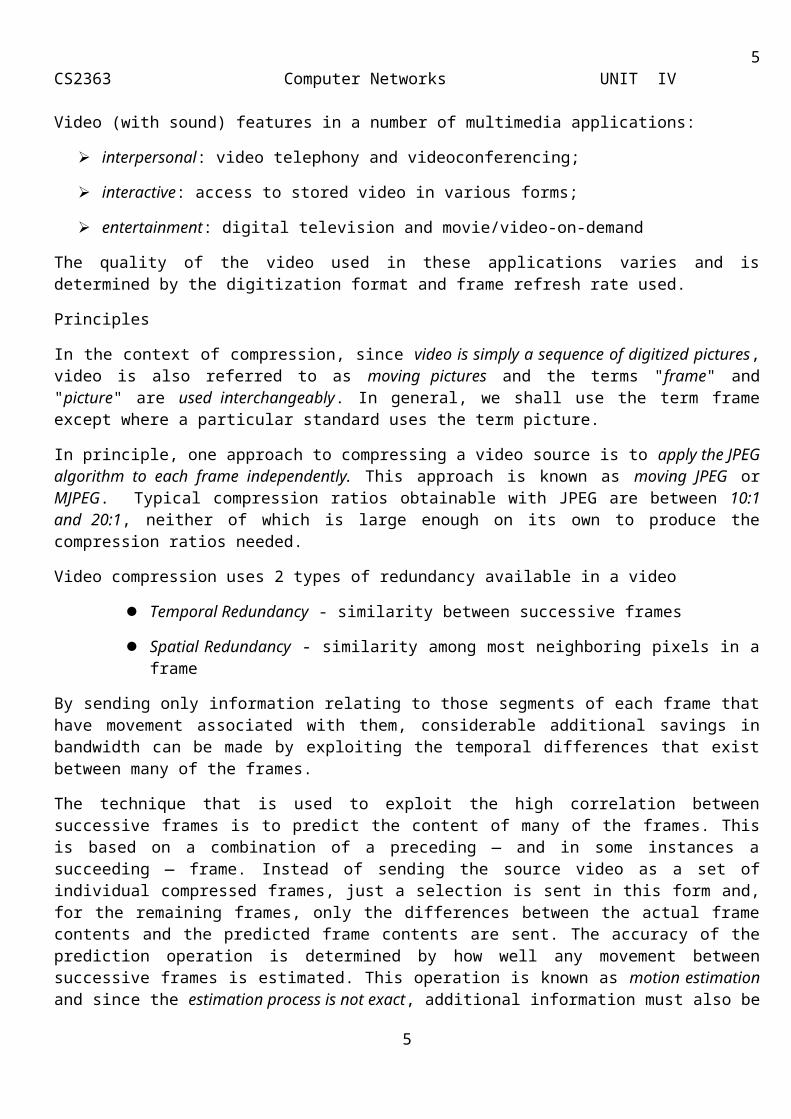
Video (with sound) features in a number of multimedia applications:
interpersonal: video telephony and videoconferencing;
interactive: access to stored video in various forms;
entertainment: digital television and movie/video-on-demand
The quality of the video used in these applications varies and is determined by the digitization format and frame refresh rate used.
Principles
In the context of compression, since video is simply a sequence of digitized pictures, video is also referred to as moving pictures and the terms "frame" and "picture" are used interchangeably. In general, we shall use the term frame except where a particular standard uses the term picture.
In principle, one approach to compressing a video source is to apply the JPEG algorithm to each frame independently. This approach is known as moving JPEG or MJPEG. Typical compression ratios obtainable with JPEG are between 10:1 and 20:1, neither of which is large enough on its own to produce the compression ratios needed.
Video compression uses 2 types of redundancy available in a video
Temporal Redundancy - similarity between successive frames
Spatial Redundancy - similarity among most neighboring pixels in a frame
3
4CS2363 Computer Networks UNIT IV
By sending only information relating to those segments of each frame that have movement associated with them, considerable additional savings in bandwidth can be made by exploiting the temporal differences that exist between many of the frames.
The technique that is used to exploit the high correlation between successive frames is to predict the content of many of the frames. This is based on a combination of a preceding — and in some instances a succeeding — frame. Instead of sending the source video as a set of individual compressed frames, just a selection is sent in this form and, for the remaining frames, only the differences between the actual frame contents and the predicted frame contents are sent. The accuracy of the prediction operation is determined by how well any movement between successive frames is estimated. This operation is known as motion estimation and since the estimation process is not exact, additional information must also be sent to indicate any small differences between the predicted and actual positions of the moving segments involved. The latter is known as motion compensation and we shall discus each issue separately.
Frame types - I,B,P frames
I – Frames
o Coded without reference to other frames
o Each frame is treated as digital pictures Y, Cb,Cr matrices are encoded independently using JPEG algorithm
o Quantization threshold values used are same for all DCT coefficients
o Level of compression – relatively small
o Must be present in the output stream at regular intervals. Clearly, if an I-frame was corrupted then, in the case of a movie, since the predicted frames are based on the contents of an I-frame, a complete scene would be lost which, of course, would be totally unacceptable. Normally, therefore, I-frames are inserted into the output stream relative frequently.
o The number of frames/pictures between successive I-frames known as a group of pictures or GOP. - N – varies from 3 to 12, as shown in Figure 3.20 – (a).
4
Compressed Frame
Predicted Frame
Predictive or P Frame
Bidirectional or B Frame [intercoded
or interpolation frame]
Intracoded or I Frame
5CS2363 Computer Networks UNIT IV
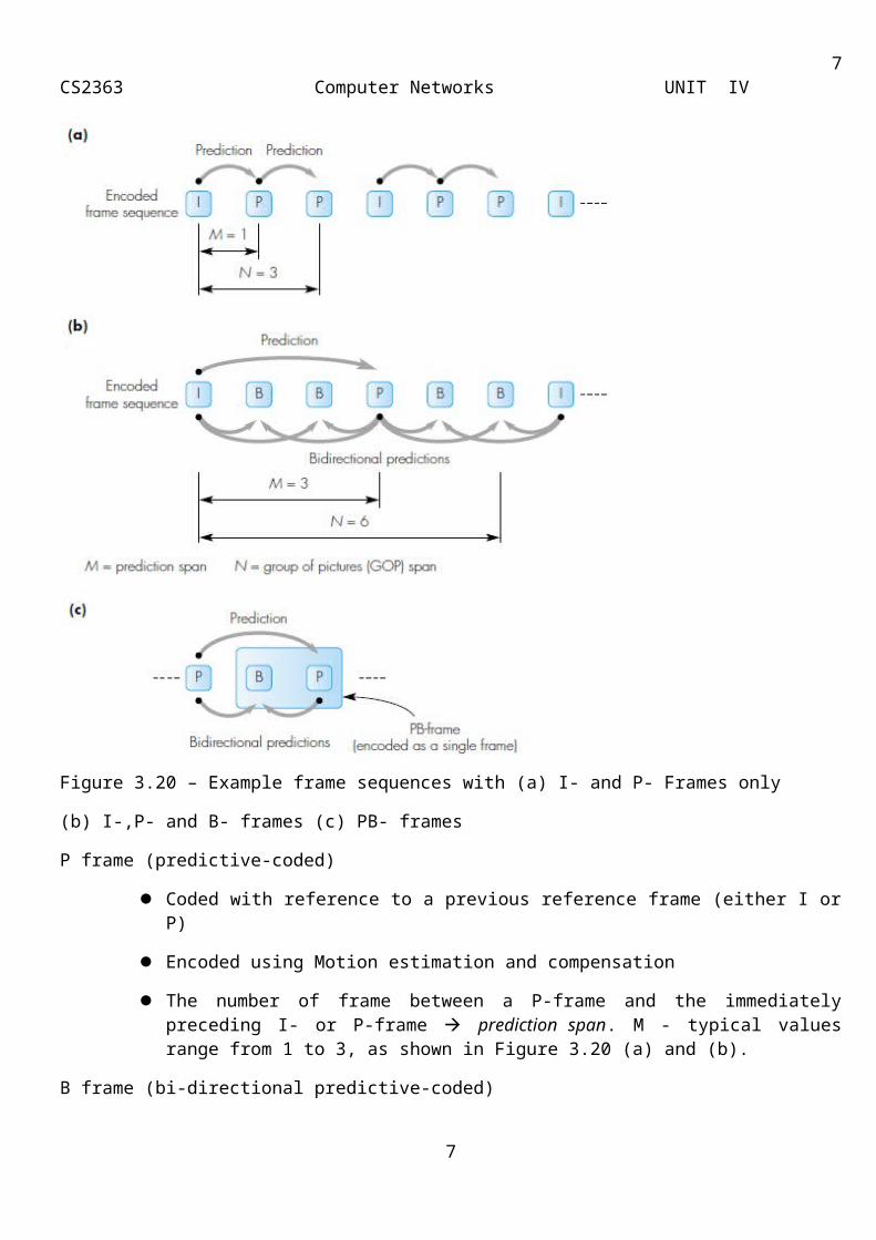
Figure 3.20 – Example frame sequences with (a) I- and P- Frames only
(b) I-,P- and B- frames (c) PB- frames
P frame (predictive-coded)
Coded with reference to a previous reference frame (either I or P)
Encoded using Motion estimation and compensation
The number of frame between a P-frame and the immediately preceding I- or P-frame prediction span. M - typical values range from 1 to 3, as shown in Figure 3.20 (a) and (b).
B frame (bi-directional predictive-coded)
Coded with reference to both previous and future reference frames (either I or P)
High compression ratio
5

6CS2363 Computer Networks UNIT IV
Since B frame depends on future frame increase in encoding and decoding delay = time to wait for the next I- or P- frame in the sequence
Do not propagate errors, because they are not involoved in the coding of other frames.
Encoding of Frames
To minimize the time required to decode each B-frame, the order of encoding (and transmission) of the (encoded) frames is changed so that both the pre-ceding and succeeding I- or P-frames are available when the B-frame is received.
Uncoded Frame Sequence
IBBPBBPBBI...
Recorded Sequence
IPBBPBBIBB…
PB – frame
It does not refer to a new frame type as such but rather the way two neighboring P- and B-frames are encoded as if they were a single frame.
It is used to increase the frame rate without significantly increasing the resulting bit rate required.
D- Frame (DCT Frame)
It is used in movie/video-on-demand applications. With this type of application, a user (at home) can select and watch a particular movie/video which is stored in a remote server connected to a network. The selection operation is performed by means of a set-top box and, as with a VCR, the user may wish to rewind or fast-forward through the movie.
It requires the compressed video to be decompressed at much higher speeds.
They are highly compressed frames and are ignored during the decoding of P- and B-frames.
Uses only the encoded DC coefficients of each block of pixels in the periodically inserted D-frames a low-resolution sequence of frames is provided each of which can be decoded at the higher speeds that are expected with the rewind and fast-forward operations.
Motion estimation and compensation
As showed earlier in Figure 3.20, the encoded contents of both P- and. B-frames are predicted by estimating any motion that has taken place between the frame being encoded and the preceding I- or P-frame and, in the case of B-frames, the succeeding P- or I-frame. The various steps that are involved in encoding each P-frame are shown in Figure 3.21.
As we show in Figure 3.21(a), the digitized contents of the Y matrix associated with each frame are first divided into a two-dimensional matrix of 16 x16 pixels known as a macroblock. Here the 4:1:1 digitization format is assumed and hence the related Cb, and Cr matrices in the macroblock are both 8 x 8 pixels. For identification purposes, each macroblock has an address associated with it and, since the block size used for the DCT operation is also 8 x 8 pixels, a macroblock comprises four DCT blocks for luminance and one each for the two chrominance signals.
6
7CS2363 Computer Networks UNIT IV
Figure 3.21 - P frame encoding – (a) macroblock structure (b)encoding procedure
Encoding of P- Frame
To encode a P-frame, the contents of each macroblock in the frame —known as the target frame — are compared on a pixel-by-pixel basis with the contents of the corresponding macroblock in the preceding -I or P-frame. The latter is known as the reference frame.
If a close match is found, then only the address of the macroblock is encoded.
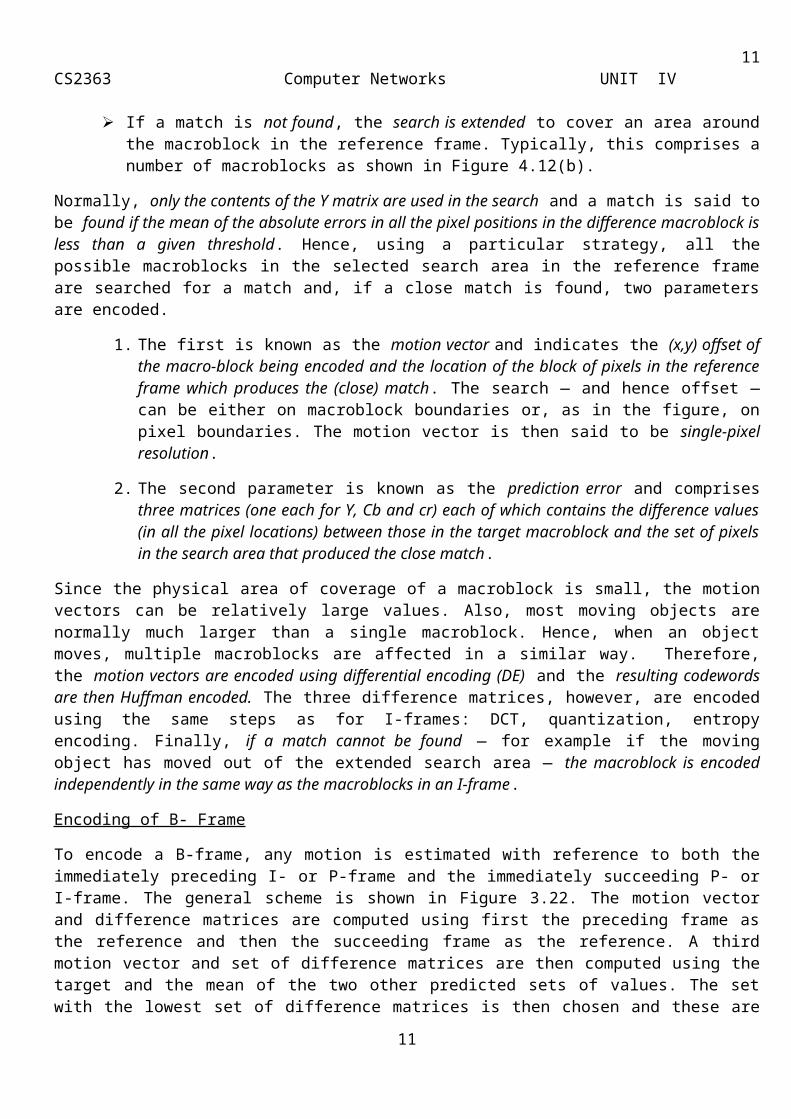
If a match is not found, the search is extended to cover an area around the macroblock in the reference frame. Typically, this comprises a number of macroblocks as shown in Figure 4.12(b).
Normally, only the contents of the Y matrix are used in the search and a match is said to be found if the mean of the absolute errors in all the pixel positions in the difference macroblock is less than a given threshold . Hence, using a particular strategy, all the possible macroblocks in the selected search area in the reference frame are searched for a match and, if a close match is found, two parameters are encoded.
7
8CS2363 Computer Networks UNIT IV
1. The first is known as the motion vector and indicates the (x,y) offset of the macro-block being encoded and the location of the block of pixels in the reference frame which produces the (close) match. The search — and hence offset — can be either on macroblock boundaries or, as in the figure, on pixel boundaries. The motion vector is then said to be single-pixel resolution.
2. The second parameter is known as the prediction error and comprises three matrices (one each for Y, Cb and cr) each of which contains the difference values (in all the pixel locations) between those in the target macroblock and the set of pixels in the search area that produced the close match.
Since the physical area of coverage of a macroblock is small, the motion vectors can be relatively large values. Also, most moving objects are normally much larger than a single macroblock. Hence, when an object moves, multiple macroblocks are affected in a similar way. Therefore, the motion vectors are encoded using differential encoding (DE) and the resulting codewords are then Huffman encoded. The three difference matrices, however, are encoded using the same steps as for I-frames: DCT, quantization, entropy encoding. Finally, if a match cannot be found — for example if the moving object has moved out of the extended search area — the macroblock is encoded independently in the same way as the macroblocks in an I-frame.
Encoding of B- Frame
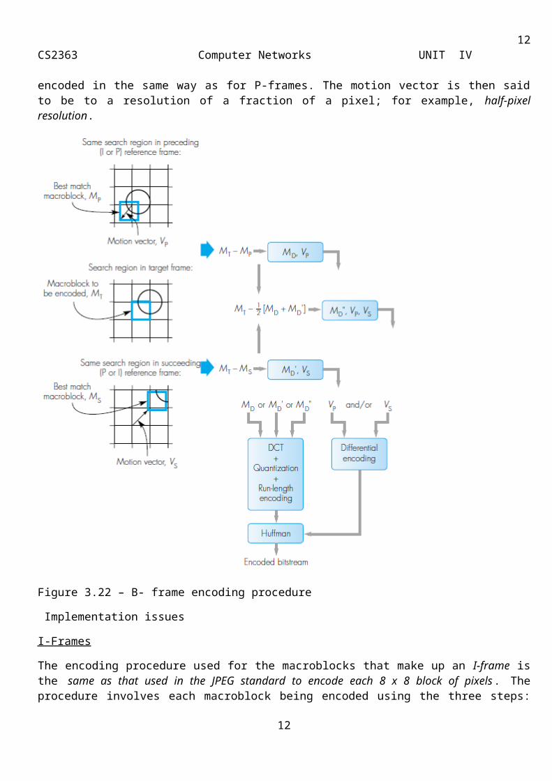
To encode a B-frame, any motion is estimated with reference to both the immediately preceding I- or P-frame and the immediately succeeding P- or I-frame. The general scheme is shown in Figure 3.22. The motion vector and difference matrices are computed using first the preceding frame as the reference and then the succeeding frame as the reference. A third motion vector and set of difference matrices are then computed using the target and the mean of the two other predicted sets of values. The set with the lowest set of difference matrices is then chosen and these are encoded in the same way as for P-frames. The motion vector is then said to be to a resolution of a fraction of a pixel; for example, half-pixel resolution.
8

9CS2363 Computer Networks UNIT IV
Figure 3.22 – B- frame encoding procedure
Implementation issues
I-Frames
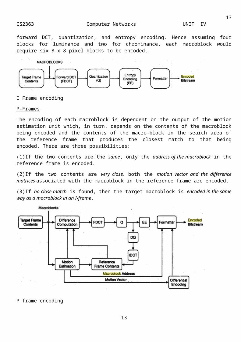
The encoding procedure used for the macroblocks that make up an I-frame is the same as that used in the JPEG standard to encode each 8 x 8 block of pixels. The procedure involves each macroblock being encoded using the three steps: forward DCT, quantization, and entropy encoding. Hence assuming four blocks for luminance and two for chrominance, each macroblock would require six 8 x 8 pixel blocks to be encoded.
9

10CS2363 Computer Networks UNIT IV
I Frame encoding
P-Frames
The encoding of each macroblock is dependent on the output of the motion estimation unit which, in turn, depends on the contents of the macroblock being encoded and the contents of the macro-block in the search area of the reference frame that produces the closest match to that being encoded. There are three possibilities:
(1)If the two contents are the same, only the address of the macroblock in the reference frame is encoded.
(2)If the two contents are very close, both the motion vector and the difference matrices associated with the macroblock in the reference frame are encoded.
(3)If no close match is found, then the target macroblock is encoded in the same way as a macroblock in an I-frame.
P frame encoding
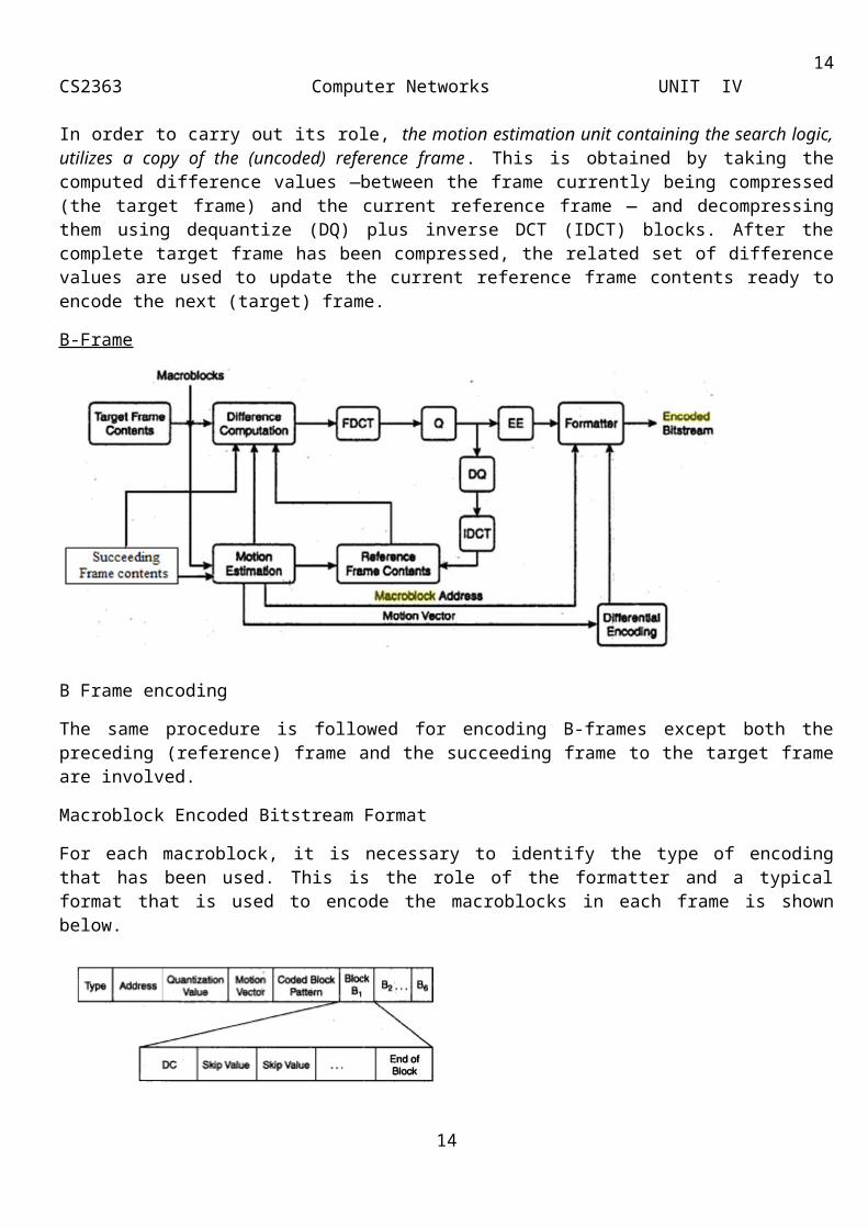
In order to carry out its role, the motion estimation unit containing the search logic, utilizes a copy of the (uncoded) reference frame. This is obtained by taking the computed difference values —between the frame currently being compressed (the target frame) and the current reference frame — and decompressing them using dequantize (DQ) plus inverse DCT (IDCT) blocks. After the complete target frame has been compressed, the related set of difference values are used to update the current reference frame contents ready to encode the next (target) frame.
B-Frame
10
11CS2363 Computer Networks UNIT IV
B Frame encoding
The same procedure is followed for encoding B-frames except both the preceding (reference) frame and the succeeding frame to the target frame are involved.
Macroblock Encoded Bitstream Format
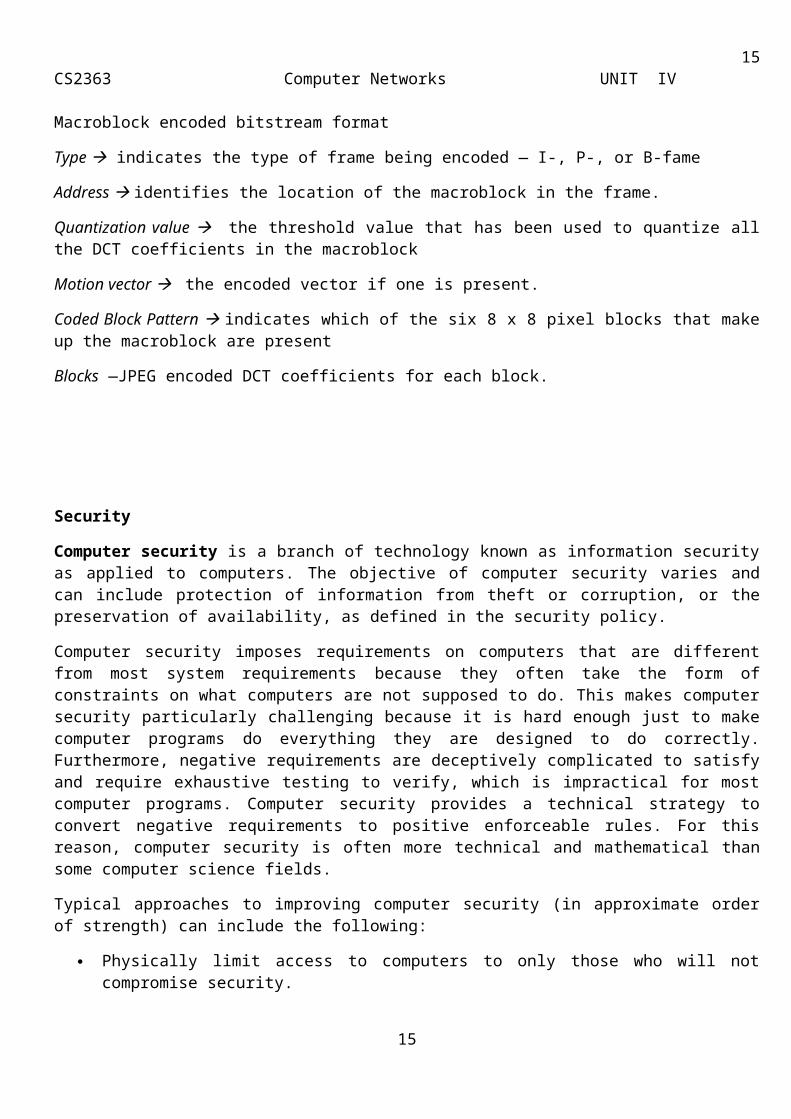
For each macroblock, it is necessary to identify the type of encoding that has been used. This is the role of the formatter and a typical format that is used to encode the macroblocks in each frame is shown below.
Macroblock encoded bitstream format
Type indicates the type of frame being encoded — I-, P-, or B-fame
Address identifies the location of the macroblock in the frame.
Quantization value the threshold value that has been used to quantize all the DCT coefficients in the macroblock
Motion vector the encoded vector if one is present.
Coded Block Pattern indicates which of the six 8 x 8 pixel blocks that make up the macroblock are present
Blocks —JPEG encoded DCT coefficients for each block.
11
12CS2363 Computer Networks UNIT IV
Security
Computer security is a branch of technology known as information security as applied to computers. The objective of computer security varies and can include protection of information from theft or corruption, or the preservation of availability, as defined in the security policy.
Computer security imposes requirements on computers that are different from most system requirements because they often take the form of constraints on what computers are not supposed to do. This makes computer security particularly challenging because it is hard enough just to make computer programs do everything they are designed to do correctly. Furthermore, negative requirements are deceptively complicated to satisfy and require exhaustive testing to verify, which is impractical for most computer programs. Computer security provides a technical strategy to convert negative requirements to positive enforceable rules. For this reason, computer security is often more technical and mathematical than some computer science fields.
Typical approaches to improving computer security (in approximate order of strength) can include the following:
Physically limit access to computers to only those who will not compromise security.
Hardware mechanisms that impose rules on computer programs, thus avoiding depending on computer programs for computer security.
Operating system mechanisms that impose rules on programs to avoid trusting computer programs.
Programming strategies to make computer programs dependable and resist subversion.
Security measures that are applied to each single message are
1. Privacy: It means that the sender and the receiver expect confidentiality. The transmitted message must make sense to only the intended receiver. A good privacy technique quarantees to some extent that a potential intruder cannot understand the contents of the messsage. Privacy can be achieved by using either symmetric-key cryptography or public-key crytography, which are discussed under the section cryptography.
2. Message authentication: It means that the receiver needs to be sure of the sender’s identity and that an imposter has not sent the message. Digital signature can provide message authentication.
3. Message integrity: It means that the data must arrive at the receiver exactly as they were sent. There must be no change during the transmission either accidental or malicious. Digital signature can provide message integrity.
4. Nonrepudiation: It means that a receiver must be able to prove that a received message came from a specific sender. The sender must not be able to deny sending a message that he or she, in fact, did send. The burden of proof falls on the receiver. Digital signature can provide nonrepudiation.
Cryptography is the practice and study of hiding information. In modern times, cryptography is considered a branch of both mathematics and computer science, and is affiliated closely with information theory, computer security, and engineering. Cryptography is used in applications present in technologically advanced societies; examples include the security of ATM cards, computer passwords, and electronic commerce, which all depend on cryptography.
12
13CS2363 Computer Networks UNIT IV
Figure 5.34 Cryptography components
Figure 5.34 shows the various components of cryptography. The original message, before being transformed, is called plaintext. After the message is transformed, it is called ciphertext. An encryption algorithm transforms the plaintext to ciphertext; a decryption algorithm transforms the ciphertext back to plaintext. The sender uses an encryption algorithm and the receiver uses a decryption algorithm. The term cipher is also used to refer to different categories of algorithms in cryptography. A key is a number that the cipher, as an algorithm, operates on. To encrypt a message, we need an encryption algorithm, an encryption key and the plaintext. To decrypt a message, we need a decryption algorithm, a decryption key and the ciphertext. Figure 5.35 show the idea of encryption and decryption.
The encryption and decryption algorithms are public; anyone can access them. The keys are secret they need to be protected. The modern field of cryptography can be broadly divided as: Symmetric-key cryptography and Public-key cryptography.
Figure 5.35 Encryption and decryption
Symmetric-key cryptography: It refers to encryption methods in which both the sender and receiver share the same key. In symmetric-key cryptography, the algorithm used for decryption is the inverse of the algorithm used for encryption. This means that if the encryption algorithm uses a combination of addition and multiplication, the decryption algorithm uses a combination of division and subtraction. They are named so, since the same key is used for both encryption as well as decryption.
Symmetric-key algorithms are efficient, when compared to public-key algorithms, since the key is usually smaller. Hence they are used for long messages. The symmetric-key algorithm has two major disadvantages. Each pair of users must have a unique symmetric key. The distribution of the keys between the parties might be difficult.
Traditional ciphers: In the earliest and simplest ciphers, a character was the unit of data to be encrypted. These traditional ciphers involved either substitution or transposition.
Substitution Cipher: It substitutes one symbol with another. If the symbols in the plaintext are alphabetic characters, we replace one character with another. Substitution can either be mono-alphabetic or poly-alphabetic.
o Ceaser Cipher, is an example for mono-alphabetic cipher. In mono-alphabetic cipher the relationship between a character in the plaintext and a character in the ciphertext is always one-to-one. Mono-alphabetic cipher is very simple and the code can be attacked easily. This cipher cannot hide the natural frequencies of characters in the language being used. An attacker can
13
14CS2363 Computer Networks UNIT IV
easily break the code by finding which character is used the most and replace that one with the letter E. He can then find the next most frequent and replace it with T, and so on.
o Vignere cipher, is an example of poly-alphabetic cipher. In poly-alphabetic cipher the relationship between a character in the plaintext to a character in the ciphertext is one-to-many. In one version of Vignere cipher, the character in the ciphertext is chosen from a two-dimensional table, in which each row is a permutation of 26 characters. To change a character, the algorithm finds the character to be encrypted in the first row. It finds the position of the character in the text and uses it as the row number. The algorithm then replaces the character with the character found in the table. A ciphertext created by poly-alphabetic cipher is harder to attack when compared to that of mono-alphabetic cipher. Although the frequencies of the characters change, the character relationships are maintained in this cipher. A good trial-and-error attack can break the code.
Transpositional Cipher: In this method the characters retain their plaintext form but change their positions to create the ciphertext. The text is organized into a two dimensional table, and the columns are interchanged according to a key. The key defines which columns should be swapped. Since the character frequencies are preserved the attacker can find the plaintext through trail and error. This method can be combined with other methods to provide more sophisticated ciphers.
Modern Cipher: The modern study of symmetric-key ciphers relates mainly to the study of block ciphers and stream ciphers and to their applications. A block cipher take as input a block of plaintext and a key, and output a block of ciphertext of the same size. Since messages are almost always longer than a single block, some method of knitting together successive blocks is required. Several have been developed, some with better security in one aspect or another than others. They are the mode of operations and must be carefully considered when using a block cipher in a cryptosystem.
P-box: It performs a transposition at the bit level; it transposes bits. It can be implemented in hardware or software, but hardware is faster. The key and the encryption/decryption algorithm are normally embedded in the hardware.
S-box: It performs a substitution at the bit-level; it transposes permuted bits. It substitutes one decimal digit with another. It normally has three components: an encoder, a decoder and a P-box. The decoder changes an input of n bits to an output of 2n bits. This output has one single 1 located at a position determined by the input. The P-box permutes the output of the decoder and the encoder changes the output of the P-box back to a binary number in the same way as the decoder, but inversely.
The Data Encryption Standard (DES) and the Advanced Encryption Standard (AES) are block cipher designs which have been designated cryptography standards by the US government. Despite its deprecation as an official standard, DES (especially its still-approved and much more secure triple-DES variant) remains quite popular; it is used across a wide range of applications, from ATM encryption to e-mail privacy and secure remote access. Many other block ciphers have been designed and released, with considerable variation in quality. Many have been thoroughly broken.
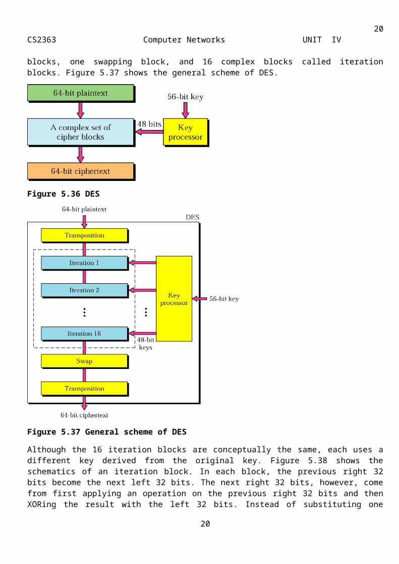
The DES algorithm encrypts a 64-bit plaintext using a 56-bit key. The text is put through 19 different and complex procedures to create a 64-bit ciphertext, as shown in Figure 5.36. DES has two transposition blocks, one swapping block, and 16 complex blocks called iteration blocks. Figure 5.37 shows the general scheme of DES.
14
15CS2363 Computer Networks UNIT IV
Figure 5.36 DES
Figure 5.37 General scheme of DES
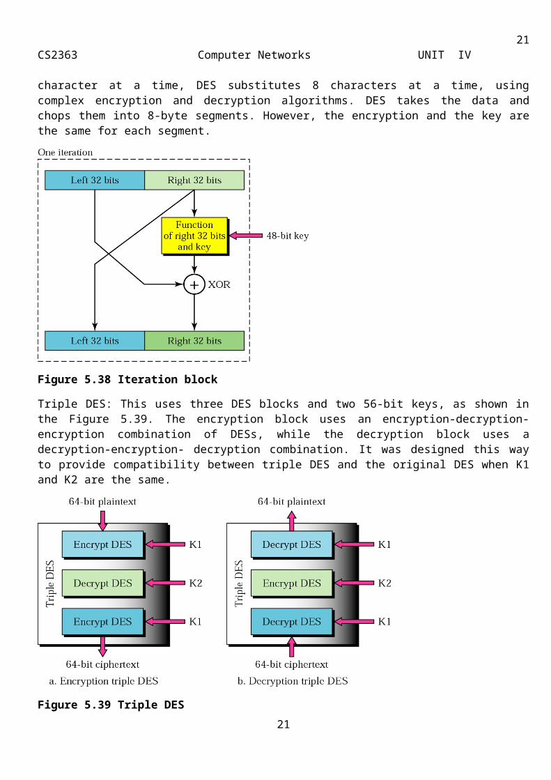
Although the 16 iteration blocks are conceptually the same, each uses a different key derived from the original key. Figure 5.38 shows the schematics of an iteration block. In each block, the previous right 32 bits become the next left 32 bits. The next right 32 bits, however, come from first applying an operation on the previous right 32 bits and then XORing the result with the left 32 bits. Instead of substituting one character at a time, DES substitutes 8 characters at a time, using complex encryption and decryption algorithms. DES takes the data and chops them into 8-byte segments. However, the encryption and the key are the same for each segment.
15
16CS2363 Computer Networks UNIT IV
Figure 5.38 Iteration block
Triple DES: This uses three DES blocks and two 56-bit keys, as shown in the Figure 5.39. The encryption block uses an encryption-decryption-encryption combination of DESs, while the decryption block uses a decryption-encryption- decryption combination. It was designed this way to provide compatibility between triple DES and the original DES when K1 and K2 are the same.
Figure 5.39 Triple DES
DES and Triple DES are actually long substitution ciphers that operate on eight-character segments. Several modes have been defined, the four most common ones are mentioned below:
Electronic Code Book (EBC) mode: It divides the long message into 64-bit blocks and encrypts each block separately, as shown in Figure 5.40.
16

17CS2363 Computer Networks UNIT IV
Figure 5.40: ECB mode
Cipher Block Chaining (CBC) mode: The encryption of a block depend on all previous blocks, as shown in Figure 5.41.
Figure 5.41: CBC mode
Cipher Feedback Mode (CFM): Used when we need to send or receive data 1 byte at a time, but still want to use DES, as shown in Figure 5.42.
Figure 5.42 CFM
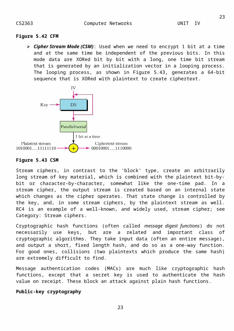
Cipher Stream Mode (CSM): Used when we need to encrypt 1 bit at a time and at the same time be independent of the previous bits. In this mode data are XORed bit by bit with a long, one time bit stream that is generated by an initialization vector in a looping process. The looping process, as shown in Figure 5.43, generates a 64-bit sequence that is XORed with plaintext to create ciphertext.
17
18CS2363 Computer Networks UNIT IV
Figure 5.43 CSM
Stream ciphers, in contrast to the 'block' type, create an arbitrarily long stream of key material, which is combined with the plaintext bit-by-bit or character-by-character, somewhat like the one-time pad. In a stream cipher, the output stream is created based on an internal state which changes as the cipher operates. That state change is controlled by the key, and, in some stream ciphers, by the plaintext stream as well. RC4 is an example of a well-known, and widely used, stream cipher; see Category: Stream ciphers.
Cryptographic hash functions (often called message digest functions) do not necessarily use keys, but are a related and important class of cryptographic algorithms. They take input data (often an entire message), and output a short, fixed length hash, and do so as a one-way function. For good ones, collisions (two plaintexts which produce the same hash) are extremely difficult to find.
Message authentication codes (MACs) are much like cryptographic hash functions, except that a secret key is used to authenticate the hash value on receipt. These block an attack against plain hash functions.
Public-key cryptography
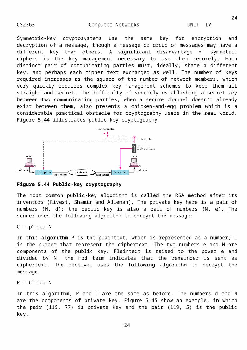
Symmetric-key cryptosystems use the same key for encryption and decryption of a message, though a message or group of messages may have a different key than others. A significant disadvantage of symmetric ciphers is the key management necessary to use them securely. Each distinct pair of communicating parties must, ideally, share a different key, and perhaps each cipher text exchanged as well. The number of keys required increases as the square of the number of network members, which very quickly requires complex key management schemes to keep them all straight and secret. The difficulty of securely establishing a secret key between two communicating parties, when a secure channel doesn't already exist between them, also presents a chicken-and-egg problem which is a considerable practical obstacle for cryptography users in the real world. Figure 5.44 illustrates public-key cryptography.
Figure 5.44 Public-key cryptography
18
19CS2363 Computer Networks UNIT IV
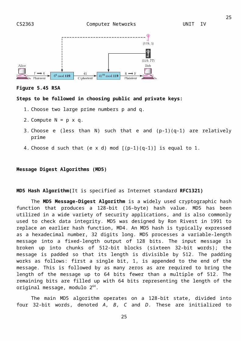
The most common public-key algorithm is called the RSA method after its inventors (Rivest, Shamir and Adleman). The private key here is a pair of numbers (N, d); the public key is also a pair of numbers (N, e). The sender uses the following algorithm to encrypt the message:
C = pe mod N
In this algorithm P is the plaintext, which is represented as a number; C is the number that represent the ciphertext. The two numbers e and N are components of the public key. Plaintext is raised to the power e and divided by N. the mod term indicates that the remainder is sent as ciphertext. The receiver uses the following algorithm to decrypt the message:
P = Cd mod N
In this algorithm, P and C are the same as before. The numbers d and N are the components of private key. Figure 5.45 show an example, in which the pair (119, 77) is private key and the pair (119, 5) is the public key.
Figure 5.45 RSA
Steps to be followed in choosing public and private keys:
1. Choose two large prime numbers p and q.
2. Compute N = p x q.
3. Choose e (less than N) such that e and (p-1)(q-1) are relatively prime
4. Choose d such that (e x d) mod [(p-1)(q-1)] is equal to 1.
Message Digest Algorithms (MD5)
MD5 Hash Algorithm(It is specified as Internet standard RFC1321)
The MD5 Message-Digest Algorithm is a widely used cryptographic hash function that produces a 128-bit (16-byte) hash value. MD5 has been utilized in a wide variety of security applications, and is also commonly used to check data integrity. MD5 was designed by Ron Rivest in 1991 to replace an earlier hash function, MD4. An MD5 hash is typically expressed as a hexadecimal number, 32 digits long. MD5 processes a variable-length message into a fixed-length output of 128 bits. The input message is broken up into chunks of 512-bit blocks (sixteen 32-bit words); the message is padded so that its length is divisible by 512. The padding works as follows: first a single bit, 1, is appended to the end of the message. This is followed by as many zeros as are required to bring the length of the message up to 64 bits fewer than a multiple of 512. The remaining bits are filled up with 64 bits representing the length of the original message, modulo 264.
19
20CS2363 Computer Networks UNIT IV
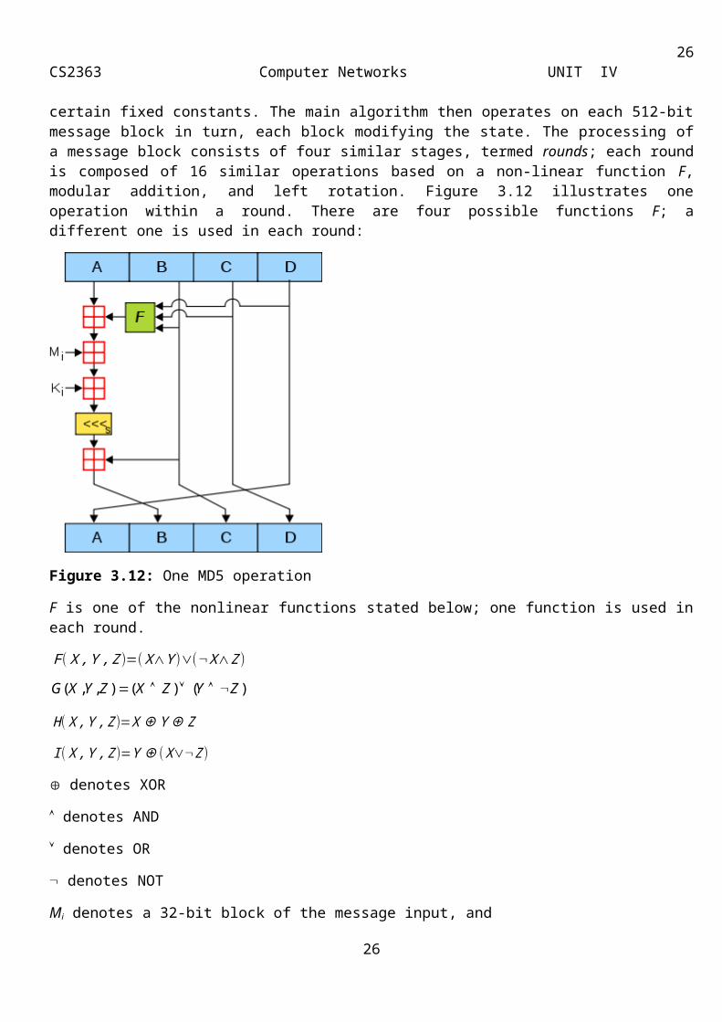
The main MD5 algorithm operates on a 128-bit state, divided into four 32-bit words, denoted A, B, C and D. These are initialized to certain fixed constants. The main algorithm then operates on each 512-bit message block in turn, each block modifying the state. The processing of a message block consists of four similar stages, termed rounds; each round is composed of 16 similar operations based on a non-linear function F, modular addition, and left rotation. Figure 3.12 illustrates one operation within a round. There are four possible functions F; a different one is used in each round:
Figure 3.12: One MD5 operation
F is one of the nonlinear functions stated below; one function is used in each round.
F (X ,Y , Z )=(X∧Y )∨(¬X∧Z )
H (X ,Y , Z )=X⊕Y⊕Z
I (X ,Y , Z )=Y ⊕( X∨¬Z )
denotes XOR
denotes AND
denotes OR
denotes NOT
Mi denotes a 32-bit block of the message input, and
Ki denotes a 32-bit constant, different for each operation.
s denotes a left bit rotation by s places; s varies for each operation.
denotes addition modulo 232.
20
)()(),,( ZYZXZYXG
21CS2363 Computer Networks UNIT IV
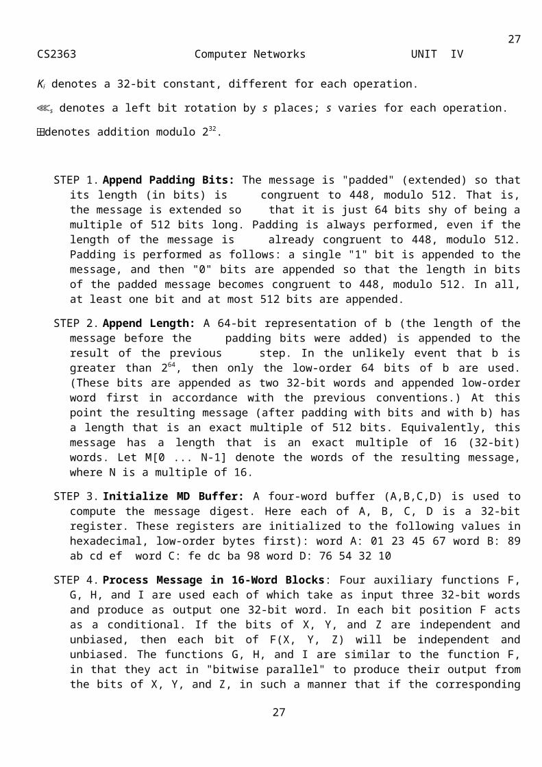
STEP 1. Append Padding Bits: The message is "padded" (extended) so that its length (in bits) is congruent to 448, modulo 512. That is, the message is extended so that it is just 64 bits shy of being a multiple of 512 bits long. Padding is always performed, even if the length of the message is already congruent to 448, modulo 512. Padding is performed as follows: a single "1" bit is appended to the message, and then "0" bits are appended so that the length in bits of the padded message becomes congruent to 448, modulo 512. In all, at least one bit and at most 512 bits are appended.
STEP 2. Append Length: A 64-bit representation of b (the length of the message before the padding bits were added) is appended to the result of the previous step. In the unlikely event that b is greater than 264, then only the low-order 64 bits of b are used. (These bits are appended as two 32-bit words and appended low-order word first in accordance with the previous conventions.) At this point the resulting message (after padding with bits and with b) has a length that is an exact multiple of 512 bits. Equivalently, this message has a length that is an exact multiple of 16 (32-bit) words. Let M[0 ... N-1] denote the words of the resulting message, where N is a multiple of 16.
STEP 3. Initialize MD Buffer: A four-word buffer (A,B,C,D) is used to compute the message digest. Here each of A, B, C, D is a 32-bit register. These registers are initialized to the following values in hexadecimal, low-order bytes first): word A: 01 23 45 67 word B: 89 ab cd ef word C: fe dc ba 98 word D: 76 54 32 10
STEP 4. Process Message in 16-Word Blocks: Four auxiliary functions F, G, H, and I are used each of which take as input three 32-bit words and produce as output one 32-bit word. In each bit position F acts as a conditional. If the bits of X, Y, and Z are independent and unbiased, then each bit of F(X, Y, Z) will be independent and unbiased. The functions G, H, and I are similar to the function F, in that they act in "bitwise parallel" to produce their output from the bits of X, Y, and Z, in such a manner that if the corresponding bits of X, Y and Z are independent and unbiased, then each bit of G(X,Y,Z), H(X,Y,Z) and I(X,Y,Z) will be independent and unbiased. Function H is the bit-wise "xor" or "parity" function of its inputs. This step uses a 64-element table T[1 ... 64] constructed from the sine function. Let T[i] denote the i-th element of the table, which is equal to the integer part of 4294967296 times abs(sin(i)), where i is in radians. Do the following:
Save the current block words ABCD in buffer and the perform 4 rounds of operations as stated below
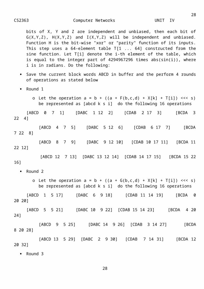
Round 1
o Let the operation a = b + ((a + F(b,c,d) + X[k] + T[i]) <<< s) be represented as [abcd k s i] do the following 16 operations
[ABCD 0 7 1] [DABC 1 12 2] [CDAB 2 17 3] [BCDA 3 22 4]
[ABCD 4 7 5] [DABC 5 12 6] [CDAB 6 17 7] [BCDA 7 22 8]
[ABCD 8 7 9] [DABC 9 12 10] [CDAB 10 17 11] [BCDA 11 22 12]
[ABCD 12 7 13] [DABC 13 12 14] [CDAB 14 17 15] [BCDA 15 22 16]
Round 2
o Let the operation a = b + ((a + G(b,c,d) + X[k] + T[i]) <<< s) be represented as [abcd k s i] do the following 16 operations
21

22CS2363 Computer Networks UNIT IV
[ABCD 1 5 17] [DABC 6 9 18] [CDAB 11 14 19] [BCDA 0 20 20]
[ABCD 5 5 21] [DABC 10 9 22] [CDAB 15 14 23] [BCDA 4 20 24]
[ABCD 9 5 25] [DABC 14 9 26] [CDAB 3 14 27] [BCDA 8 20 28]
[ABCD 13 5 29] [DABC 2 9 30] [CDAB 7 14 31] [BCDA 12 20 32]
Round 3
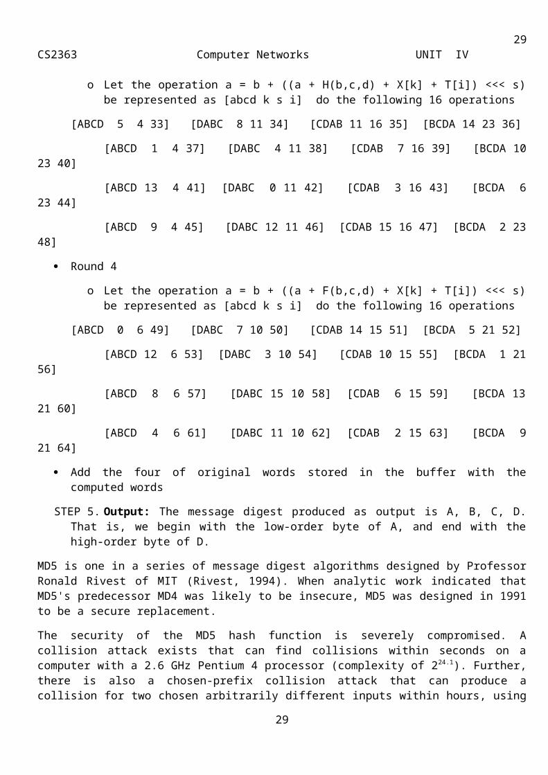
o Let the operation a = b + ((a + H(b,c,d) + X[k] + T[i]) <<< s) be represented as [abcd k s i] do the following 16 operations
[ABCD 5 4 33] [DABC 8 11 34] [CDAB 11 16 35] [BCDA 14 23 36]
[ABCD 1 4 37] [DABC 4 11 38] [CDAB 7 16 39] [BCDA 10 23 40]
[ABCD 13 4 41] [DABC 0 11 42] [CDAB 3 16 43] [BCDA 6 23 44]
[ABCD 9 4 45] [DABC 12 11 46] [CDAB 15 16 47] [BCDA 2 23 48]
Round 4
o Let the operation a = b + ((a + F(b,c,d) + X[k] + T[i]) <<< s) be represented as [abcd k s i] do the following 16 operations
[ABCD 0 6 49] [DABC 7 10 50] [CDAB 14 15 51] [BCDA 5 21 52]
[ABCD 12 6 53] [DABC 3 10 54] [CDAB 10 15 55] [BCDA 1 21 56]
[ABCD 8 6 57] [DABC 15 10 58] [CDAB 6 15 59] [BCDA 13 21 60]
[ABCD 4 6 61] [DABC 11 10 62] [CDAB 2 15 63] [BCDA 9 21 64]
Add the four of original words stored in the buffer with the computed words
STEP 5. Output: The message digest produced as output is A, B, C, D. That is, we begin with the low-order byte of A, and end with the high-order byte of D.
MD5 is one in a series of message digest algorithms designed by Professor Ronald Rivest of MIT (Rivest, 1994). When analytic work indicated that MD5's predecessor MD4 was likely to be insecure, MD5 was designed in 1991 to be a secure replacement.
The security of the MD5 hash function is severely compromised. A collision attack exists that can find collisions within seconds on a computer with a 2.6 GHz Pentium 4 processor (complexity of 224.1). Further, there is also a chosen-prefix collision attack that can produce a collision for two chosen arbitrarily different inputs within hours, using off-the-shelf computing hardware (complexity 239). These hash and collision attacks have been demonstrated in the public in various situations, including colliding document files and digital certificates. In 1996, collisions were found in the compression function of MD5, and Hans Dobbertin wrote about it in the RSA Laboratories technical newsletter.
MD5 uses the Merkle–Damgård construction, so if two prefixes with the same hash can be constructed, a common suffix can be added to both to make the collision more likely to be accepted as valid data by the application using it. Furthermore, current collision-finding techniques allow specifying an arbitrary prefix: an attacker can create two colliding files that both begin with the same content. All the attacker needs to generate
22
23CS2363 Computer Networks UNIT IV
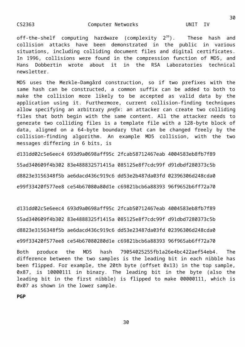
two colliding files is a template file with a 128-byte block of data, aligned on a 64-byte boundary that can be changed freely by the collision-finding algorithm. An example MD5 collision, with the two messages differing in 6 bits, is
d131dd02c5e6eec4 693d9a0698aff95c 2fcab58712467eab 4004583eb8fb7f89
55ad340609f4b302 83e488832571415a 085125e8f7cdc99f d91dbdf280373c5b
d8823e3156348f5b ae6dacd436c919c6 dd53e2b487da03fd 02396306d248cda0
e99f33420f577ee8 ce54b67080a80d1e c69821bcb6a88393 96f9652b6ff72a70
d131dd02c5e6eec4 693d9a0698aff95c 2fcab50712467eab 4004583eb8fb7f89
55ad340609f4b302 83e4888325f1415a 085125e8f7cdc99f d91dbd7280373c5b
d8823e3156348f5b ae6dacd436c919c6 dd53e23487da03fd 02396306d248cda0
e99f33420f577ee8 ce54b67080280d1e c69821bcb6a88393 96f965ab6ff72a70
Both produce the MD5 hash 79054025255fb1a26e4bc422aef54eb4. The difference between the two samples is the leading bit in each nibble has been flipped. For example, the 20th byte (offset 0x13) in the top sample, 0x87, is 10000111 in binary. The leading bit in the byte (also the leading bit in the first nibble) is flipped to make 00000111, which is 0x07 as shown in the lower sample.
PGP
Pretty Good Privacy (PGP) is a popular approach to providing encryption and authentication capabilities for electronic mail. The most interesting aspect of PGP is how it handles certificates. Recall that the basic problem of distribution of public keys is the establishment of a chain of trust. PGP acknowledges that each user has his own set of criteria by which he wants to trust keys certified by someone else and provides the tools needed to manage the level of trust he puts in these certificates. To quote Phil Zimmerman, the developer of PGP, “PGP is for people who prefer to pack their own parachutes.”
Keyrings
PGP provides a pair of data structures at each node, one to store the public/private key pair owned by that node and one to store the public keys of the other users known at that node. These data structures are referred to as private key ring and public key ring.
An individual can
collect public keys from others whose identity he knows
provide his public key to others get his public key signed by others, thus collecting certificates that will be persuasive to an increasingly large set of people
sign the public key of other individuals, thus helping them build up their set of certificates that they can use to distribute their public keys
collect certificates from other individuals whom he trusts enough to sign keys
23
24CS2363 Computer Networks UNIT IV
Thus over time a user will collect a set of certificates with varying degrees of trust. PGP stores these in a file called a key ring.
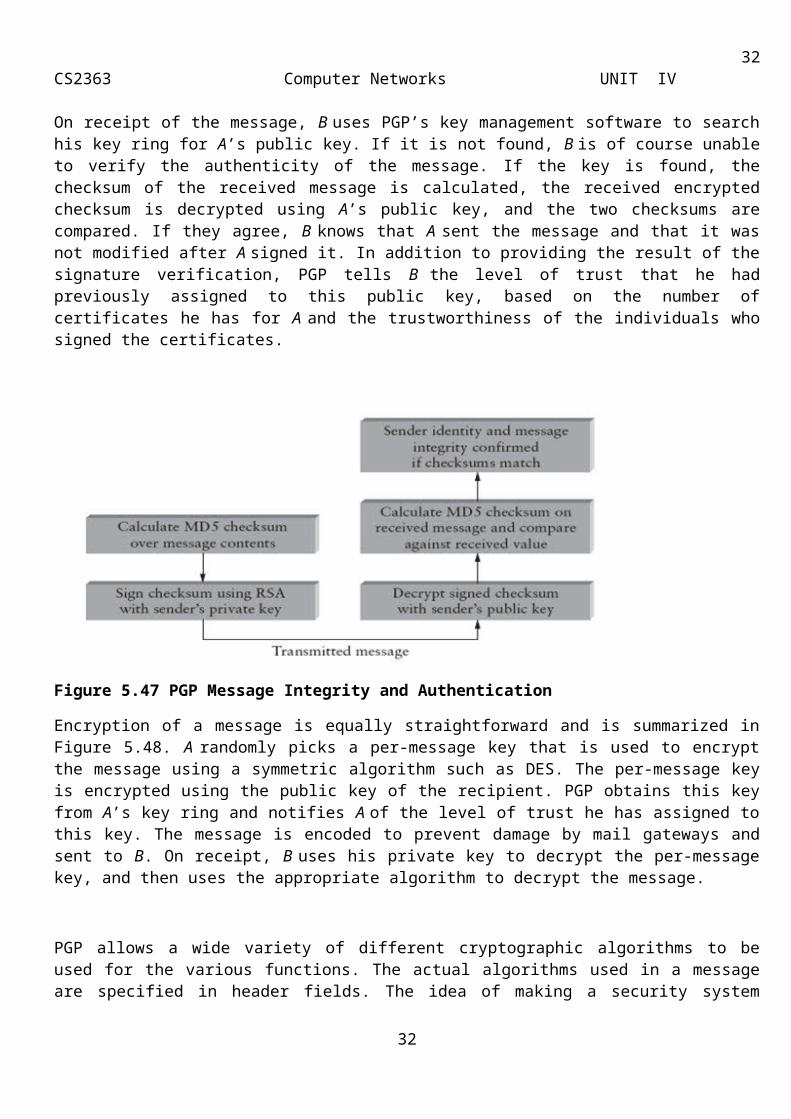
Now suppose user A wants to send a message to user B and prove to B that it truly came from A. PGP follows the sequence of steps shown in Figure 5.47. First, A creates a cryptographic checksum over the message body (e.g., using MD5) and then encrypts the checksum using A’s private key. (PGP allows a variety of different cryptographic algorithms to be used and specifies which one is used in the message.)
On receipt of the message, B uses PGP’s key management software to search his key ring for A’s public key. If it is not found, B is of course unable to verify the authenticity of the message. If the key is found, the checksum of the received message is calculated, the received encrypted checksum is decrypted using A’s public key, and the two checksums are compared. If they agree, B knows that A sent the message and that it was not modified after A signed it. In addition to providing the result of the signature verification, PGP tells B the level of trust that he had previously assigned to this public key, based on the number of certificates he has for A and the trustworthiness of the individuals who signed the certificates.
Figure 5.47 PGP Message Integrity and Authentication
Encryption of a message is equally straightforward and is summarized in Figure 5.48. A randomly picks a per-message key that is used to encrypt the message using a symmetric algorithm such as DES. The per-message key is encrypted using the public key of the recipient. PGP obtains this key from A’s key ring and notifies A of the level of trust he has assigned to this key. The message is encoded to prevent damage by mail gateways and sent to B. On receipt, B uses his private key to decrypt the per-message key, and then uses the appropriate algorithm to decrypt the message.
PGP allows a wide variety of different cryptographic algorithms to be used for the various functions. The actual algorithms used in a message are specified in header fields. The idea of making a security system protocol-independent is a very good one, because you never know when your favourite cryptographic
24
25CS2363 Computer Networks UNIT IV
algorithm might be proved to be insufficiently strong for your purposes. It would be nice if you could quickly change to a new algorithm without having to change the protocol specification or implementation.
Figure 5.48 PGP Message Encryption
In addition to putting this information in a mail message, PGP allows a user to list his preferred algorithms in the file that contains his public key. Thus, anyone who has his public key will know which algorithms can be safely used when sending to that person.
SSH
The Secure Shell (SSH) provides a remote login service and is intended to replace the less secure Telnet and rlogin programs used in the early days of the Internet. (SSH can also be used to remotely execute commands and transfer files, like the Unix rsh and rcp commands, respectively, but we will focus on how SSH supports remote login.)
SSH is most often used to provide strong client/server authentication—where the SSH client runs on the user’s desktop machine and the SSH server runs on some remote machine that the user wants to log into—but it also supports message integrity and confidentiality. Telnet and rlogin provide none of these capabilities.
SSH provides a way to encrypt the data sent over these connections and to improve the strength of the authentication mechanism they use to login.
The latest version of SSH, version 2, consists of three protocols:
■ SSH-TRANS: a transport layer protocol
■ SSH-AUTH: an authentication protocol
■ SSH-CONN: a connection protocol
We focus on the first two, which are involved in remote login.
25
26CS2363 Computer Networks UNIT IV
SSH-TRANS provides an encrypted channel between the client and server machines. It runs on top of a TCP connection. Any time a user uses SSH to log onto a remote machine, the first step is to set up an SSH-TRANS channel between those two machines. The two machines establish this secure channel by first having the client authenticate the server using RSA. Once authenticated, the client and server establish a session key that they will use to encrypt any data sent over the channel.
SSH then remembers the server’s public key, and the next time the user connects to that same machine, it compares this saved key with the one the server responds with. If they are the same, SSH authenticates the server. If they are different, however, SSH again warns the user that something is amiss, and the user is then given an opportunity to abort the connection. Alternatively, the prudent user can learn the server’s public key through some out-of-band mechanism, save it on the client machine, and thus never take the “first time” risk.
Once the SSH-TRANS channel exists, the next step is for the user to actually log onto the machine, or more specifically, authenticate him- or herself to the server. SSH allows three different mechanisms for doing this. First, since the two machines are communicating over a secure channel, it is OK for the user to simply send his or her password to the server.
The second mechanism uses public key encryption. This requires that the user has already placed his or her public key on the server. The third mechanism, called host-based authentication, basically says that any user claiming to be so-and-so from a certain set of trusted hosts is automatically believed to be that same user on the server. Host-based authentication requires that the client host authenticate itself to the server when they first connect; standard SSH-TRANS only authenticate the server by default.
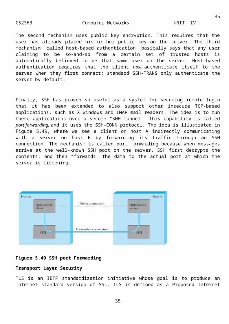
Finally, SSH has proven so useful as a system for securing remote login that it has been extended to also support other insecure TCP-based applications, such as X Windows and IMAP mail readers. The idea is to run these applications over a secure “SHH tunnel.” This capability is called port forwarding, and it uses the SSH-CONN protocol. The idea is illustrated in Figure 5.49, where we see a client on host A indirectly communicating with a server on host B by forwarding its traffic through an SSH connection. The mechanism is called port forwarding because when messages arrive at the well-known SSH port on the server, SSH first decrypts the contents, and then “forwards” the data to the actual port at which the server is listening.
26
27CS2363 Computer Networks UNIT IV
Figure 5.49 SSH port Forwarding
Transport Layer Security
TLS is an IETF standardization initiative whose goal is to produce an Internet standard version of SSL. TLS is defined as a Proposed Internet Standard in RFC 2246. RFC 2246 is very similar to SSLv3.The differences are
Version Number
The TLS Record Format is the same as that of the SSL Record Format (Figure 4.20), and the fields in the header have the same meanings. The one difference is in version values. For the current version of TLS, the Major Version is 3 and the Minor Version is 1.
Message Authentication Code
There are two differences between the SSLv3 and TLS MAC schemes: the actual algorithm and the scope of the MAC calculation. TLS makes use of the HMAC algorithm defined in RFC 2104. HMAC is defined as follows:
HMACK(M) = H[(K+ opad)||H[(K+ ipad)||M]] where
H = embedded hash function (for TLS, either MD5 or SHA-1)
M = message input to HMAC
K+ = secret key padded with zeros on the left so that the result is equal to the block length of the hash code(for MD5 and SHA-1, block length = 512 bits)
ipad = 00110110 (36 in hexadecimal) repeated 64 times (512 bits)
opad = 01011100 (5C in hexadecimal) repeated 64 times (512 bits)
SSLv3 uses the same algorithm, except that the padding bytes are concatenated with the secret key rather than being XORed with the secret key padded to the block length. The level of security should be about the same in both cases. For TLS, the MAC calculation encompasses the fields indicated in the following expression:
HMAC_hash(MAC_write_secret, seq_num || TLSCompressed.type || TLSCompressed.version || TLSCompressed.length || TLSCompressed.fragment)
27
28CS2363 Computer Networks UNIT IV
The MAC calculation covers all of the fields covered by the SSLv3 calculation, plus the field TLSCompressed.version, which is the version of the protocol being employed.
Pseudorandom Function
TLS makes use of a pseudorandom function referred to as PRF to expand secrets into blocks of data for purposes of key generation or validation. The objective is to make use of a relatively small shared secret value but to generate longer blocks of data in a way that is secure from the kinds of attacks made on hash functions and MACs. The PRF is based on the following data expansion function (Figure 4.21):
P_hash(secret, seed) = HMAC_hash(secret, A(1) || seed) || HMAC_hash(secret, A(2) || seed) ||
HMAC_hash(secret, A(3) || seed) || ...
where A() is defined as
A(0) = seed
A(i) = HMAC_hash (secret, A(i - 1))
The data expansion function makes use of the HMAC algorithm, with either MD5 or SHA-1 as the underlying hash function. As can be seen, P_hash can be iterated as many times as necessary to produce the required quantity of data. For example, if P_SHA-1 was used to generate 64 bytes of data, it would have to be iterated four times, producing 80 bytes of data, of which the last 16 would be discarded. In this case, P_MD5 would also have to be iterated four times, producing exactly 64 bytes of data. Note that each iteration involves two executions of HMAC, each of which in turn involves two executions of the underlying hash algorithm.
28
29CS2363 Computer Networks UNIT IV
Figure 4.21: TLSFunction P_hash(secret, seed)
To make PRF as secure as possible, it uses two hash algorithms in a way that should guarantee its security if either algorithm remains secure. PRF is defined as
PRF(secret, label, seed) = P_MD5(S1, label || seed) XOR
P_SHA-1(S2, label || seed)
PRF takes as input a secret value, an identifying label, and a seed value and produces an output of arbitrary length. The output is created by splitting the secret value into two halves (S1 and S2) and performing P_hash on each half, using MD5 on one half and SHA-1 on the
other half. The two results are exclusive-ORed to produce the output; for this purpose, P_MD5 will generally have to be iterated more times than P_SHA-1 to produce an equal amount of data for input to the exclusive-OR function.
Alert Codes
29
30CS2363 Computer Networks UNIT IV
TLS supports all of the alert codes defined in SSLv3 with the exception of no_certificate. A number of additional codes are defined in TLS; of these, the following are always fatal:
decryption_failed: A ciphertext decrypted in an invalid way; either it was not an even multiple of the block length or its padding values, when checked, were incorrect.
record_overflow: A TLS record was received with a payload (ciphertext) whose length exceeds 214 + 2048 bytes, or the ciphertext decrypted to a length of greater than 214 + 1024 bytes.
unknown_ca: A valid certificate chain or partial chain was received, but the certificate was not accepted because the CA certificate could not be located or could not be matched with a known, trusted CA.
access_denied: A valid certificate was received, but when access control was applied, the sender decided not to proceed with the negotiation.
decode_error: A message could not be decoded because a field was out of its specified range or the length of the message was incorrect.
export_restriction: A negotiation not in compliance with export restrictions on key length was detected.
protocol_version: The protocol version the client attempted to negotiate is recognized but not supported.
insufficient_security: Returned instead of handshake_failure when a negotiation has failed specifically because the server requires ciphers more secure than those supported by the client.
internal_error: An internal error unrelated to the peer or the correctness of the protocol makes it impossible to continue.
The remainder of the new alerts include the following:
decrypt_error: A handshake cryptographic operation failed, including being unable to verify a signature, decrypt a key exchange, or validate a finished message.
user_canceled: This handshake is being canceled for some reason unrelated to a protocol failure.
no_renegotiation: Sent by a client in response to a hello request or by the server in response to a client hello after initial handshaking. Either of these messages would normally result in renegotiation, but this alert indicates that the sender is not able to renegotiate. This message is always a warning.
Cipher Suites
There are several small differences between the cipher suites available under SSLv3 and under TLS:
Key Exchange: TLS supports all of the key exchange techniques of SSLv3 with the exception of Fortezza.
Symmetric Encryption Algorithms: TLS includes all of the symmetric encryption algorithms found in SSLv3, with the exception of Fortezza.
Client Certificate Types
TLS defines the following certificate types to be requested in a certificate_request message: rsa_sign, dss_sign, rsa_fixed_dh, and dss_fixed_dh. These are all defined in SSLv3. In addition, SSLv3 includes rsa_ephemeral_dh, dss_ephemeral_dh, and fortezza_kea. Ephemeral Diffie-Hellman involves signing the Diffie-Hellman parameters with either RSA or DSS; for TLS, the rsa_sign and dss_sign types are used for that
30
31CS2363 Computer Networks UNIT IV
function; a separate signing type is not needed to sign Diffie-Hellman parameters. TLS does not include the Fortezza scheme.
Certificate_Verify and Finished Messages
In the TLS certificate_verify message, the MD5 and SHA-1 hashes are calculated only over handshake_messages. Recall that for SSLv3, the hash calculation also included the master secret and pads. These extra fields were felt to add no additional security. As with the finished message in SSLv3, the finished message in TLS is a hash based on the shared master_secret, the previous handshake messages, and a label that identifies client or server. The calculation is somewhat different. For TLS, we have
PRF(master_secret, finished_label, MD5(handshake_messages)|| SHA-1(handshake_messages))
where finished_label is the string "client finished" for the client and "server finished" for the server.
Cryptographic Computations
The pre_master_secret for TLS is calculated in the same way as in SSLv3. As in SSLv3, the master_secret in TLS is calculated as a hash function of the pre_master_secret and the two hello random numbers. The form of the TLS calculation is different from that of SSLv3 and is defined as follows:
master_secret = PRF(pre_master_secret, "master secret",
ClientHello.random || ServerHello.random)
The algorithm is performed until 48 bytes of pseudorandom output are produced. The calculation of the key block material (MAC secret keys, session encryption keys, and IVs) is defined as follows:
key_block = PRF(master_secret, "key expansion",
SecurityParameters.server_random ||
SecurityParameters.client_random)
until enough output has been generated. As with SSLv3, the key_block is a function of the master_secret and the client and server random numbers, but for TLS the actual algorithm is different.
Padding
In SSL, the padding added prior to encryption of user data is the minimum amount required so that the total size of the data to be encrypted is a multiple of the cipher's block length. In TLS, the padding can be any amount that results in a total that is a multiple of the cipher's block length, up to a maximum of 255 bytes. For example, if the plaintext (or compressed text if compression is used) plus MAC plus padding.length byte is 79 bytes long, then the padding length, in bytes, can be 1, 9, 17, and so on, up to 249. A variable padding length may be used to frustrate attacks based on an analysis of the lengths of exchanged messages.
IP Security
Authentication and Encryption are necessary security features in the next-generation IP, which has been issued as IPv6. Fortunately, these security capabilities were designed to be usable both with the current IPv4 and the future IPv6.
31
32CS2363 Computer Networks UNIT IV
Applications of IPSec
IPSec provides the capability to secure communications across a LAN, across private and public WANs, and across the Internet. Examples of its use include the following:
Secure branch office connectivity over the Internet: A company can build a secure virtual private network over the Internet or over a public WAN. This enables a business to rely heavily on the Internet and reduce its need for private networks, saving costs and network management overhead.
Secure remote access over the Internet: An end user whose system is equipped with IP security protocols can make a local call to an Internet service provider (ISP) and gain secure access to a company network. This reduces the cost of toll charges for traveling employees and telecommuters.
Establishing extranet and intranet connectivity with partners: IPSec can be used to secure communication with other organizations, ensuring authentication and confidentiality and providing a key exchange mechanism.
Enhancing electronic commerce security: Even though some Web and electronic commerce applications have built-in security protocols, the use of IPSec enhances that security.
Figure 4.10 is a typical scenario of IPSec usage. An organization maintains LANs at dispersed locations. Nonsecure IP traffic is conducted on each LAN. For traffic offsite, through some sort of private or public WAN, IPSec protocols are used. These protocols operate in networking devices, such as a router or firewall that connect each LAN to the outside world. The IPSec networking device will typically encrypt and compress all traffic going into the WAN, and decrypt and decompress traffic coming from the WAN; these operations are transparent to workstations and servers on the LAN. Secure transmission is also possible with individual users who dial into the WAN. Such user workstations must implement the IPSec protocols to provide security.
Figure 4.10: An IP Security Scenario
Benefits of IPSec
When IPSec is implemented in a firewall or router, it provides strong security that can be applied to all traffic crossing the perimeter. Traffic within a company or workgroup does not incur the overhead of security-related processing.
32

33CS2363 Computer Networks UNIT IV
IPSec in a firewall is resistant to bypass if all traffic from the outside must use IP, and the firewall is the only means of entrance from the Internet into the organization.
IPSec is below the transport layer (TCP, UDP) and so is transparent to applications. There is no need to change software on a user or server system when IPSec is implemented in the firewall or router. Even if IPSec is implemented in end systems, upper-layer software, including applications, is not affected.
IPSec can be transparent to end users. There is no need to train users on security mechanisms, issue keying material on a per-user basis, or revoke keying material when users leave the organization.
IPSec can provide security for individual users if needed. This is useful for offsite workers and for setting up a secure virtual subnetwork within an organization for sensitive applications.
Routing Applications
IPSec can play a vital role in the routing architecture required for internetworking. IPsec can assure that
A router advertisement (a new router advertises its presence) comes from an authorized router
A neighbor advertisement (a router seeks to establish or maintain a neighbor relationship with a router in another routing domain) comes from an authorized router.
A redirect message comes from the router to which the initial packet was sent.
A routing update is not forged.
IP Security Architecture
The IPSec specification consists of numerous documents. The documents are divided into seven groups, as depicted in Figure 4.11
Architecture: Covers the general concepts, security requirements, definitions, and mechanisms defining IPSec technology.
Encapsulating Security Payload (ESP): Covers the packet format and general issues related to the use of the ESP for packet encryption and, optionally, authentication.
Authentication Header (AH): Covers the packet format and general issues related to the use of AH for packet authentication.
Encryption Algorithm: A set of documents that describe how various encryption algorithms are used for ESP.
Authentication Algorithm: A set of documents that describe how various authentication algorithms are used for AH and for the authentication option of ESP.
Key Management: Documents that describe key management schemes.
Domain of Interpretation (DOI): Contains values needed for the other documents to relate to each other. These include identifiers for approved encryption and authentication algorithms, as well as operational parameters such as key lifetime.
33
34CS2363 Computer Networks UNIT IV
Figure 4.11: IPSec Document Overview
IPSec Services
IPSec provides security services at the IP layer by enabling a system to select required security protocols, determine the algorithm(s) to use for the service(s), and put in place any cryptographic keys required to provide the requested services. Two protocols are used to provide security: an authentication protocol designated by the header of the protocol, Authentication Header (AH); and a combined encryption/authentication protocol designated by the format of the packet for that protocol, Encapsulating Security Payload (ESP). The
services are
Access control
Connectionless integrity
Data origin authentication
Rejection of replayed packets (a form of partial sequence integrity)
Confidentiality (encryption)
Limited traffic flow confidentiality
Security Associations
A security association is uniquely identified by three parameters:
34
35CS2363 Computer Networks UNIT IV
Security Parameters Index (SPI): A bit string assigned to this SA and having local significance only. The SPI is carried in AH and ESP headers to enable the receiving system to select the SA under which a received packet will be processed.
IP Destination Address: Currently, only unicast addresses are allowed; this is the address of the destination endpoint of the SA, which may be an end user system or a network system such as a firewall or router.
Security Protocol Identifier: This indicates whether the association is an AH or ESP security association.
SA Parameters
A security association is normally defined by the following parameters:
Sequence Number Counter: A 32-bit value used to generate the Sequence Number field in AH or ESP headers.
Sequence Counter Overflow: A flag indicating whether overflow of the Sequence Number Counter should generate an auditable event and prevent further transmission of packets on this SA (required for all implementations).
Anti-Replay Window: Used to determine whether an inbound AH or ESP packet is a replay.
AH Information: Authentication algorithm, keys, key lifetimes, and related parameters being used with AH.
ESP Information: Encryption and authentication algorithm, keys, initialization values, key lifetimes, and related parameters being used with ESP (required for ESP implementations).
Lifetime of This Security Association: A time interval or byte count after which an SA must be replaced with a new SA (and new SPI) or terminated, plus an indication of which of these actions should occur (required for all implementations).
IPSec Protocol Mode: Tunnel, transport, or wildcard (required for all implementations). Path MTU: Any observed path maximum transmission unit (maximum size of a packet that can be transmitted without fragmentation) and aging variables (required for all implementations)
SA Selectors
IPSec provides the user with considerable flexibility in the way in which IPSec services are applied to IP traffic. SAs can be combined in a number of ways to yield the desired user configuration. Furthermore, IPSec provides a high degree of granularity in discriminating between traffic that is afforded IPSec protection and traffic that is allowed to bypass IPSec, in the former case relating IP traffic to specific SAs.
The means by which IP traffic is related to specific SAs (or no SA in the case of traffic allowed to bypass IPSec) is the nominal Security Policy Database (SPD). In its simplest form, an SPD contains entries, each of which defines a subset of IP traffic and points to an SA for that traffic. In more complex environments, there may be multiple entries that potentially relate to a single SA or multiple SAs associated with a single SPD entry. The reader is referred to the relevant IPSec documents for a full discussion. Each SPD entry is defined by a set of IP and upper-layer protocol field values, called selectors. In effect, these selectors are used to filter outgoing traffic in order to map it into a particular SA. Outbound processing obeys the following general sequence for each IP packet:
1. Compare the values of the appropriate fields in the packet (the selector fields) against the SPD to find a matching SPD entry, which will point to zero or more SAs.
35

36CS2363 Computer Networks UNIT IV
2. Determine the SA if any for this packet and its associated SPI.
3. Do the required IPSec processing (i.e., AH or ESP processing).
The following selectors determine an SPD entry:
Destination IP Address: This may be a single IP address, an enumerated list or range of addresses, or a wildcard (mask) address. The latter two are required to support more than one destination system sharing the same SA (e.g., behind a firewall).
Source IP Address: This may be a single IP address, an enumerated list or range of addresses, or a wildcard (mask) address. The latter two are required to support more than one source system sharing the same SA (e.g., behind a firewall).
UserID: A user identifier from the operating system. This is not a field in the IP or upper-layer headers but is available if IPSec is running on the same operating system as the user.
Data Sensitivity Level: Used for systems providing information flow security.
Transport Layer Protocol: Obtained from the IPv4 Protocol or IPv6 Next Header field. This may be an individual protocol number, a list of protocol numbers, or a range of protocol numbers.
Source and Destination Ports: These may be individual TCP or UDP port values, an enumerated list of ports, or a wildcard port.
Transport and Tunnel Modes
Both AH and ESP support two modes of use: transport and tunnel mode.
Transport Mode
Transport mode provides protection primarily for upper-layer protocols. That is, transport mode protection extends to the payload of an IP packet. Examples include a TCP or UDP segment or an ICMP packet, all of which operate directly above IP in a host protocol stack. Typically, transport mode is used for end-to-end communication between two hosts (e.g., a client and a server, or two workstations). When a host runs AH or ESP over IPv4, the payload is the data that normally follow the IP header. For IPv6, the payload is the data that normally
follow both the IP header and any IPv6 extensions headers that are present, with the possible exception of the destination options header, which may be included in the protection.
ESP in transport mode encrypts and optionally authenticates the IP payload but not the IP header. AH in transport mode authenticates the IP payload and selected portions of the IP header.
Tunnel Mode
Tunnel mode provides protection to the entire IP packet. To achieve this, after the AH or ESP fields are added to the IP packet, the entire packet plus security fields is treated as the payload of new "outer" IP packet with a new outer IP header. The entire original, or inner, packet travels through a "tunnel" from one point of an IP network to another; no routers along the way are able to examine the inner IP header. Because the original packet is encapsulated, the new, larger packet may have totally different source and destination addresses, adding to the security. Tunnel mode is used when one or both ends of an SA are a security gateway, such as a firewall or router that implements IPSec. With tunnel mode, a number of hosts on networks behind firewalls may engage in secure communications without implementing IPSec. The unprotected packets generated by
36
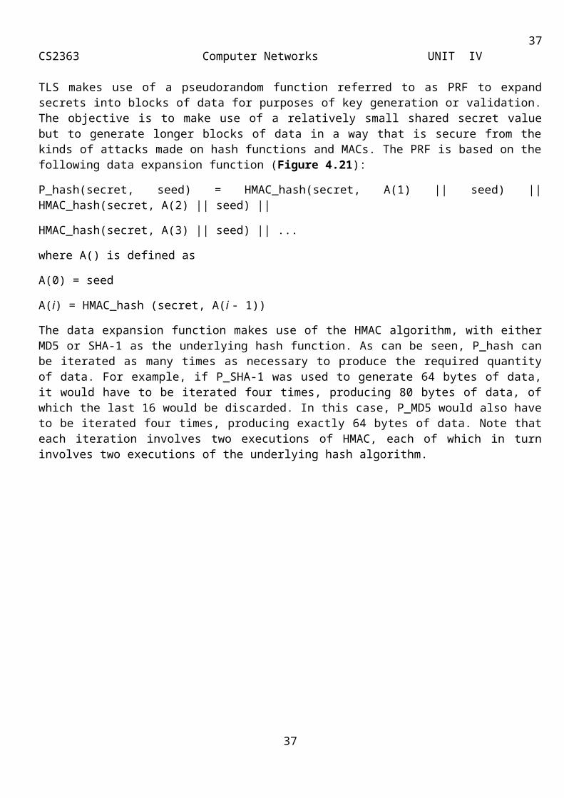
37CS2363 Computer Networks UNIT IV
such hosts are tunneled through external networks by tunnel mode SAs set up by the IPSec software in the firewall or secure router at the boundary of the local network.
Here is an example of how tunnel mode IPSec operates. Host A on a network generates an IP packet with the destination address of host B on another network. This packet is routed from the originating host to a firewall or secure router at the boundary of A's network. The firewall filters all outgoing packets to determine the need for IPSec processing. If this packet from A to B requires IPSec, the firewall performs IPSec processing and encapsulates the packet with an outer IP header. The source IP address of this outer IP packet is this firewall, and the destination address may be a firewall that forms the boundary to B's local network. This packet is now routed to B's firewall, with intermediate routers examining only the outer IP header. At B's firewall, the outer IP header is stripped off, and the inner packet is delivered to B. ESP in tunnel mode encrypts and optionally authenticates the entire inner IP packet, including the inner IP header. AH in tunnel mode authenticates the entire inner IP packet and selected portions of the outer IP header.
Authentication Header
The Authentication Header consists of the following fields (Figure 4.12):
Next Header (8 bits): Identifies the type of header immediately following this header.
Payload Length (8 bits): Length of Authentication Header in 32-bit words, minus 2. For example, the default length of the authentication data field is 96 bits, or three 32-bit words. With a three-word fixed header, there are a total of six words in the header, and the Payload Length field has a value of 4.
Reserved (16 bits): For future use.
Security Parameters Index (32 bits): Identifies a security association.
Sequence Number (32 bits): A monotonically increasing counter value, discussed later.
Authentication Data (variable): A variable-length field (must be an integral number of 32-bit words) that contains the Integrity Check Value (ICV), or MAC, for this packet.
Figure 4.12: IPSec Authentication Header
Transport and Tunnel Modes
Figure 4.13 shows two ways in which the IPSec authentication service can be used. In one case, authentication is provided directly between a server and client workstations; the workstation can be either on the same network as the server or on an external network. As long as the workstation and the server share a protected secret key, the authentication process is secure. This case uses a transport mode SA. In the other case, a remote workstation authenticates itself to the corporate firewall, either for access to the entire internal
37

38CS2363 Computer Networks UNIT IV
network or because the requested server does not support the authentication feature. This case uses a tunnel mode SA.
Figure 4.13: End-to-End versus End-to-Intermediate Authentication
In this subsection, authentication provided by AH and the authentication header location for the two modes are discussed. The considerations are somewhat different for IPv4 and IPv6. Figure 4.14 a shows typical IPv4 and IPv6 packets. In this case, the IP payload is a TCP segment; it could also be a data unit for any other protocol that uses IP, such as UDP or ICMP. For transport mode AH using IPv4, the AH is inserted after the original IP header and before the IP payload (e.g., a TCP segment); this is shown in the upper part of Figure 4.14 b. Authentication covers the entire packet, excluding mutable fields in the IPv4 header that are set to zero for MAC calculation.
In the context of IPv6, AH is viewed as an end-to-end payload; that is, it is not examined or processed by intermediate routers. Therefore, the AH appears after the IPv6 base header and the hop-by-hop, routing, and fragment extension headers. The destination options extension header could appear before or after the AH header, depending on the semantics desired. Again, authentication covers the entire packet, excluding mutable fields that are set to zero for MAC calculation.
For tunnel mode AH, the entire original IP packet is authenticated, and the AH is inserted between the original IP header and a new outer IP header (Figure 4.14 c). The inner IP header carries the ultimate source and destination addresses, while an outer IP header may contain different IP addresses (e.g., addresses of firewalls or other security gateways). With tunnel mode, the entire inner IP packet, including the entire inner IP header is protected by AH. The outer IP header (and in the case of IPv6, the outer IP extension headers) is protected except for mutable and unpredictable fields.
38
39CS2363 Computer Networks UNIT IV
Figure 4.14: Scope of AH Authentication
Encapsulating Security Payload
The Encapsulating Security Payload provides confidentiality services, including confidentiality of message contents and limited traffic flow confidentiality. As an optional feature, ESP can also provide an authentication service.
ESP Format
Figure 4.15 shows the format of an ESP packet. It contains the following fields:
Security Parameters Index (32 bits): Identifies a security association.
Sequence Number (32 bits): A monotonically increasing counter value; this provides an anti-replay function.
Payload Data (variable): This is a transport-level segment (transport mode) or IP packet (tunnel mode) that is protected by encryption.
Padding (0-255 bytes): Plain text in multiples of of some number in bytes.
Pad Length (8 bits): Indicates the number of pad bytes immediately preceding this field.
39
40CS2363 Computer Networks UNIT IV
Next Header (8 bits): Identifies the type of data contained in the payload data field by identifying the first header in that payload (for example, an extension header in IPv6, or an upper-layer protocol such as TCP).
Authentication Data (variable): A variable-length field (must be an integral number of 32-bit words) that contains the Integrity Check Value computed over the ESP packet minus the Authentication Data field.
Figure 4.15 IPSec ESP format
Transport and Tunnel Modes
Figure 4.16 shows two ways in which the IPSec ESP service can be used. In the upper part of the figure, encryption (and optionally authentication) is provided directly between two hosts. Figure 4.16 b shows how tunnel mode operation can be used to set up a virtual private network. In this example, an organization has four private networks interconnected across the Internet. Hosts on the internal networks use the Internet for transport of data but do not interact with other Internet-based hosts. By terminating the tunnels at the security gateway to each internal network, the configuration allows the hosts to avoid implementing the security capability. The former technique is support by a transport mode SA, while the latter technique uses a tunnel mode SA.
40
41CS2363 Computer Networks UNIT IV
Figure 4.16: Transport-Mode vs. Tunnel-Mode Encryption
Transport Mode ESP
Transport mode ESP is used to encrypt and optionally authenticate the data carried by IP (e.g., a TCP segment), as shown in Figure 4.17 a. For this mode using IPv4, the ESP header is inserted into the IP packet immediately prior to the transport-layer header (e.g., TCP, UDP, ICMP) and an ESP trailer (Padding, Pad Length, and Next Header fields) is placed after the IP packet; if authentication is selected, the ESP Authentication Data field is added after the ESP trailer. The entire transport-level segment plus the ESP trailer are encrypted. Authentication covers all of the ciphertext plus the ESP header.
41
42CS2363 Computer Networks UNIT IV
Figure 4.17: Scope of ESP Encryption and Authentication
In the context of IPv6, ESP is viewed as an end-to-end payload; that is, it is not examined or processed by intermediate routers. Therefore, the ESP header appears after the IPv6 base header and the hop-by-hop, routing, and fragment extension headers. The destination options extension header could appear before or after the ESP header, depending on the semantics desired. For IPv6, encryption covers the entire transport-level segment plus the ESP trailer plus the destination options extension header if it occurs after the ESP header. Again, authentication covers the ciphertext plus the ESP header.
Transport mode operation may be summarized as follows:
1. At the source, the block of data consisting of the ESP trailer plus the entire transport-layer segment is encrypted and the plaintext of this block is replaced with its ciphertext to form the IP packet for transmission. Authentication is added if this option is selected.
2. The packet is then routed to the destination. Each intermediate router needs to examine and process the IP header plus any plaintext IP extension headers but does not need to examine the ciphertext.
3. The destination node examines and processes the IP header plus any plaintext IP extension headers. Then, on the basis of the SPI in the ESP header, the destination node decrypts the remainder of the packet to recover the plaintext transport-layer segment.
Transport mode operation provides confidentiality for any application that uses it, thus avoiding the need to implement confidentiality in every individual application. This mode of operation is also reasonably efficient, adding little to the total length of the IP packet. One drawback to this mode is that it is possible to do traffic analysis on the transmitted packets.
42
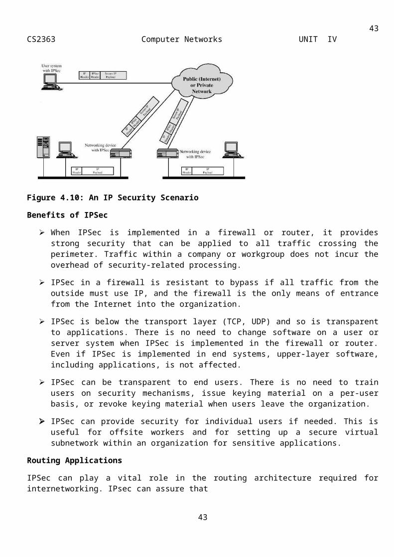
43CS2363 Computer Networks UNIT IV
Tunnel Mode ESP
Tunnel mode ESP is used to encrypt an entire IP packet (Figure 4.17 b). For this mode, the ESP header is prefixed to the packet and then the packet plus the ESP trailer is encrypted. This method can be used to counter traffic analysis. Because the IP header contains the destination address and possibly source routing directives and hop-by-hop option information, it is not possible simply to transmit the encrypted IP packet prefixed by the ESP header. Intermediate routers would be unable to process such a packet. Therefore, it is necessary to encapsulate the entire block (ESP header plus ciphertext plus Authentication Data, if present) with a new IP header that will contain sufficient information for routing but not for traffic analysis.
Whereas the transport mode is suitable for protecting connections between hosts that support the ESP feature, the tunnel mode is useful in a configuration that includes a firewall or other sort of security gateway that protects a trusted network from external networks. In this latter case, encryption occurs only between an external host and the security gateway or between two security gateways. This relieves hosts on the internal network of the processing burden of encryption and simplifies the key distribution task by reducing the number of needed keys. Further, it thwarts traffic analysis based on ultimate destination.
Consider a case in which an external host wishes to communicate with a host on an internal network protected by a firewall, and in which ESP is implemented in the external host and the firewalls. The following steps occur for transfer of a transport-layer segment from the external host to the internal host:
1. The source prepares an inner IP packet with a destination address of the target internal host. This packet is prefixed by an ESP header; then the packet and ESP trailer are encrypted and Authentication Data may b e added. The resulting block is encapsulated with a new IP header (base header plus optional extensions such as routing and hop-by-hop options for IPv6) whose destination address is the firewall; this forms the outer IP packet.
2. The outer packet is routed to the destination firewall. Each intermediate router needs to examine and process the outer IP header plus any outer IP extension headers but does not need to examine the ciphertext.
3. The destination firewall examines and processes the outer IP header plus any outer IP extension headers. Then, on the basis of the SPI in the ESP header, the destination node decrypts the remainder of the packet to recover the plaintext inner IP packet. This packet is then transmitted in the internal network.
4. The inner packet is routed through zero or more routers in the internal network to the destination host.
Key Management
The key management portion of IPSec involves the determination and distribution of secret keys. A typical requirement is four keys for communication between two applications: transmit and receive pairs for both AH and ESP. The IPSec Architecture document mandates
support for two types of key management:
Manual: A system administrator manually configures each system with its own keys and with the keys of other communicating systems. This is practical for small, relatively static environments.
Automated: An automated system enables the on-demand creation of keys for SAs and facilitates the use of keys in a large distributed system with an evolving configuration. The default automated key management protocol for IPSec is referred to as ISAKMP/Oakley and consists of the following elements:
43
44CS2363 Computer Networks UNIT IV
Oakley Key Determination Protocol: Oakley is a key exchange protocol based on the Diffie-Hellman algorithm but providing added security. Oakley is generic in that it does not dictate specific formats.
Internet Security Association and Key Management Protocol (ISAKMP): ISAKMP provides a framework for Internet key management and provides the specific protocol support, including formats, for negotiation of security attributes. ISAKMP by itself does not dictate a specific key exchange algorithm; rather, ISAKMP consists of a set of message types that enable the use of a variety of key exchange algorithms. Oakley is the specific key exchange algorithm mandated for use with the initial version of ISAKMP.
Introduction
Firewalls are a key part of keeping networked computers safe and secure. All computers deserve the protection of a firewall, whether it’s the thousands of servers and desktops that compose the network of a Fortune 500 company, a traveling salesperson’s laptop connecting to the wireless network of a coffee shop, or your grandmother’s new PC with a dial-up connection to the Internet.
This article covers the design, deployment, and use of both network and host-based firewalls (also called personal firewalls). Although home users have traditionally used only host-based firewalls, recent trends in security exploits highlight the importance of using both types of firewalls together. Traditional firewall architectures protect only the perimeter of a network. However, once an attacker penetrates that perimeter, internal systems are completely unprotected. Hybrid worms, in particular, have penetrated corporate networks through email systems, and then have spread quickly to unprotected internal systems. Applying host-based firewalls to all systems, including those behind the corporate firewall, should now be standard practice.
The Nature of Today’s Attackers
Who are these “hackers” who are trying to break into your computer? Most people imagine someone at a keyboard late at night, guessing passwords to steal confidential data from a computer system. This type of attack does happen, but it makes up a very small portion of the total network attacks that occur. Today, worms and viruses initiate the vast majority of attacks. Worms and viruses generally find their targets randomly. As a result, even organizations with little or no confidential information need firewalls to protect their networks from these automated attackers.
If a worm or a virus does find a security vulnerability and compromises your system, it can do one of several things. To begin with, it will almost always start looking for other systems to attack so that it can spread itself further. In this case, you become one of the bad guys—because the worm or virus is using your computer to attack other systems on your internal network and the Internet, wasting your computing resources and bandwidth. Even though the worm or virus won’t know what to do with your confidential data, chances are good that it will open a new back door into your system to allow someone else to further abuse your computer and compromise your privacy. Worms and viruses have dramatically increased the need for network security of all kinds—especially the need for host-based firewalls.
Individuals still launch some attacks, though, and these are generally the most dangerous. The least worrisome attackers focus on crashing computers and networks by using Denial of Service (DoS) attacks. Others might be looking for confidential data that they can abuse for profit, such as sales contacts, financial data, or customer account information. Still others might be amassing hundreds or thousands of computers from which to launch a distributed attack against a single network on the Internet.
The Firewall to the Rescue
44
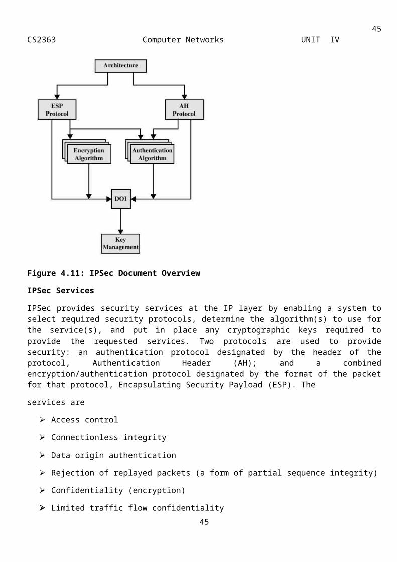
45CS2363 Computer Networks UNIT IV
In the physical world, businesses rely on several layers of security. First, they rely on their country’s government and military forces to keep order. Then, they trust their local police to patrol the streets and respond to any crimes that occur. They further supplement these public security mechanisms by using locks on doors and windows, employee badges, and security systems. If all these defenses fail and a business is a victim of a crime, the business’s insurance agency absorbs part of the impact by compensating the business for a portion of the loss.
Unfortunately, the state of networking today lacks these multiple levels of protection. Federal and local governments do what they can to slow network crime, but they’re far from 100 percent effective. Beyond prevention, law enforcement generally only responds to the most serious network intrusions. The average Internet-connected home or business is attacked dozens of times per day, and no police force is equipped to handle that volume of complaints. Losses from computer crime are hard to quantify and predict, and as a result most business insurance policies do little to compensate for the losses that result from a successful attack.
The one aspect of physical security, however, that isn’t missing from network security is the equivalent of door locks, employee badges, and security systems: firewalls. Just as you lock your car and home, you need to protect your computers and networks. Firewalls are these locks, and just like in the physical world, they come in different shapes and sizes to suit different needs. The famous Jargon Dictionary has a great definition for firewall: “a dedicated gateway machine with special security precautions on it, used to service outside network connections and dial-in lines.” Firewalls serve two useful purposes: they filter what traffic comes into your network from the outside world, and they control what computers on your network may send there.
It’s important to understand one thing, however. No firewall—whether a small, free host-based firewall or a multiple-thousand-dollar enterprise firewall array—will make your computers impervious to attack. Firewalls, like locks and walls and moats and dragons, create barriers to attack—they get in the way of someone trying to take control. By making it difficult for attackers to get into your computer, by making them invest lots of time, you become less attractive. Firewalls very effectively block most bad guys from compromising an individual computer. But it’s impossible to fully prevent every intrusion: All software has bugs, and someone might find an obscure bug in your firewall that allows them to pass through. In a nutshell, there’s no such thing as absolute security. How much you invest in firewalls should be a function of how much you have to lose if an attack is successful.
Types of Firewalls
There are two main types of firewalls: network firewalls and host-based firewalls. Network firewalls, such as the software-based Microsoft’s Internet Security and Acceleration (ISA) Server or the hardware-based Nortel Networks Alteon Switched Firewall System, protect the perimeter of a network by watching traffic that enters and leaves. Host-based firewalls, such as Internet Connection Firewall (ICF—included with Windows XP and Windows Server 2003), protect an individual computer regardless of the network it’s connected to. You might need one or the other—but most businesses require a combination of both to meet their security requirements.
How a Firewall Works
The sections that follow provide background information about network traffic and how firewalls filter traffic. This information applies to all types of firewalls.
Basic TCP/IP Flow
45
46CS2363 Computer Networks UNIT IV
This section describes how TCP/IP packages its information, to show how firewalls decide to allow or deny traffic. TCP/IP traffic is broken into packets, and firewalls must examine each packet to determine whether to drop it or forward it to the destination. Figure 1 shows a simplified breakdown of a packet with the following three key sections: the IP header, the TCP or UDP header, and the actual contents of the packet. The IP header contains the IP addresses of the source, which is the sender, and the destination, which is the receiver. The TCP or UDP header contains the source port of the sender and the destination port of the receiver to identify the applications that are sending and receiving the traffic. In addition, TCP headers contain additional information such as sequence numbers, acknowledgment numbers, and the conversation state. The destination TCP or UDP ports define the locations for delivery of the data on the server when the packet reaches its destination.
Figure 1: An IP packet contains a header useful to firewalls.
It’s important to appreciate the communication flow of a TCP/IP conversation when configuring the firewall. When a browser, for example, sends an HTTP request to a Web server, the request contains the identity of the client computer, the source IP address, and the source port that the request went out on. The source port of the client identifies the client application that sent the request—in this case, the browser. When the Web server sends a response, it uses the client’s source port as the destination port in the response. The client operating system recognizes the port number as belonging to a session the browser application started, and gives the data to the browser. The source port for a client is typically a value greater than 1024 and less than 5000.
Packet Filtering
The primary purpose of a firewall is to filter traffic. Firewalls inspect packets as they pass through, and based on the criteria that the administrator has defined, the firewall allows or denies each packet.
Firewalls block everything that you haven’t specifically allowed. Routers with filtering capabilities are a simplified example of a firewall. Administrators often configure them to allow all outbound connections from the internal network, but to block all incoming traffic. So, a user on the internal network would be able to download email without a problem, but an administrator would need to customize the router configuration to connect to your home PC from work by using Remote Desktop. Other applications that might require special firewall configuration are WebCam servers, collaboration software, and multiplayer online games.
You use packet filters to instruct a firewall to drop traffic that meets certain criteria. For example, you could create a filter that would drop all ping requests. You can also configure filters with more complex exceptions to a rule. For example, a filter might assist with troubleshooting the firewall by allowing the firewall to respond to ping requests coming from a monitoring station’s IP address. By default, Microsoft ISA Server doesn’t respond to ping queries on its external interface. You would need to create a packet filter on the ISA Server computer for it to respond to a ping request.
46

47CS2363 Computer Networks UNIT IV
The following are the main TCP/IP attributes used in implementing filtering rules:
Source IP addresses
Destination IP addresses
IP protocol
Source TCP and UDP ports
Destination TCP and UDP ports
The interface where the packet arrives
The interface where the packet is destined
If you’ve configured the firewall to allow all traffic by default, you can use filters to block specific traffic. If you’ve configured the firewall to deny all traffic, filters allow only specific traffic through. A common packet-filtering configuration is to allow inbound DNS requests from the public Internet so that a DNS service can respond.
Developers have designed most applications to work properly with both routers and host-based firewalls, but some might require you to configure your firewall to allow the application to communicate. Fortunately, firewalls are very common, and any application that requires a firewall should include information about how to configure your firewall. Host-based firewalls are easier to configure than network firewalls and generally include a wizard to walk you through the configuration process. Many host-based firewalls automatically prompt you the first time any application attempts to use the Internet—whether the connection is inbound or outbound. While using a host-based firewall, you might even notice applications that you didn’t know accessed the Internet, such as Microsoft Word. Figure 2 shows the filter configuration screen for ICF:
Figure 2: ICF allows custom filters to be created.
Figure 3 shows the filter configuration screen for a third-party firewall application, ZoneAlarm Pro:
47
48CS2363 Computer Networks UNIT IV
Figure 3: ZoneAlarm also allows custom filters to be created.
Both of these examples demonstrate enabling the Remote Desktop feature in Windows XP, which uses TCP port 3389. Most modern firewalls are friendly enough so that they hide the port numbers from you. For example, ICF allows you to choose the names of the applications that you want to allow through. However, it’s very common to need to add an application to the list of allowed traffic. To add an application, you need to know the port number that the application uses.
Table 1 shows a list of port numbers for commonly used applications. As mentioned earlier, ports can be either a TCP port or a UDP port. Most applications use TCP ports. However, DNS uses UDP, and without DNS, you wouldn’t be able to find Web sites on the Internet.
Table 1 Common Port Numbers
Service Port
Web server 80/tcp
SSL (Secure Sockets Layer) Web server 443/tcp
FTP 21/tcp
POP3 110/tcp
SMTP 25/tcp
Remote Desktop (Terminal Services) 3389/tcp
48
49CS2363 Computer Networks UNIT IV
IMAP3 220/tcp
IMAP4 143/tcp
Telnet 23/tcp
SQL Server 1433/tcp
LDAP 389/tcp
MSN Messenger 1863/tcp
Yahoo! Messenger 5050/tcp
AOL Instant Messenger and ICQ 5190/tcp
IRC (Internet Relay Chat) 6665-6669/tcp
DNS 53/udp
To use TCP/UDP port-filtering tools effectively, configure the filtering tool to accept requests through each port that your server applications require, and to refuse requests from all other TCP or UDP ports. Making a careful determination of your applications’ TCP/UDP port requirements and setting your filtering tools accordingly allows you to avoid mistakes that would deny access to the services you’re trying to provide. Filtering out all traffic to other TCP and UDP ports eliminates unnecessary exposure to attack.
Filtering Based on Source and Destination
Some types of firewalls can filter traffic based on source or destination IP address. IP addresses are the telephone numbers of the Internet: They’re the unique, numeric label that identifies a single host’s location. Filtering based on source or destination address is useful because it enables you to allow or deny traffic based on the computers or networks that are sending or receiving the traffic.
This is useful in two ways. First, you can configure firewalls to block specific Web sites. Blocking Web sites by name is a form of destination filtering. Second, firewalls can allow or deny traffic based on the computer sending the request. This allows administrators to disable instant messaging from the computer in one organization, while allowing the same protocol from a different set of computers.
Source filtering also allows you to give greater access to users on internal networks than those on external networks. It’s common to use a firewall to block all requests sent to an internal email server except those requests from users on the internal network. You can also use source filtering to block all requests from a specific address—for example, to block traffic from an IP address identified as having attacked the network.
Stateful Inspection Filtering
Stateful inspection is the process of inspecting packets as they reach the firewall and maintaining the state of the connection by allowing or disallowing packets to pass based on the access policy. To further help you understand how state is maintained, Figure 4 shows how a conversation between a client and a server takes place through the ISA Server computer. In this scenario, Web Publishing has been configured on the ISA Server computer to support redirecting external Internet requests on port 80 to the internal IIS server:
49
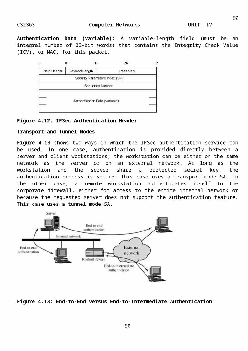
50CS2363 Computer Networks UNIT IV
Figure 4: Sample conversation through ISA Server
This is the flow of the conversation:
1. The Internet client initiates an HTTP request to the Web server and sends an IP packet with the source and destination address and ports.
2. The ISA Server computer receives the request for the Web server.
3. ISA Server then modifies the packet, replacing the source address and port with its own internal address, and changes the destination IP address to the address of the real IIS server.
4. ISA Server adds the source and destination ports and addresses into its own table to keep track of the conversation.
5. ISA Server sends the modified packet to the internal IIS server.
6. The IIS server responds to the request by using ISA Server as the destination address and TCP port 5300.
7. ISA Server receives the packet from the IIS server and looks in its table for 5300, which maps to the Internet client.
8. ISA Server then modifies the packet and replaces the IIS server’s source IP address and port with its own source IP address and port.
9. ISA Server then changes the destination IP address and TCP port to that of the Internet client.
10. The Internet client listens for a response on TCP port 5100.
In addition to maintaining the TCP or UDP conversation based on IP addresses and ports, ISA Server also checks the TCP flags, the sequence and acknowledgment numbers within the TCP header fields for TCP conversations. The flags represent the state of the conversation, whether it’s the beginning of a conversation (SYN), the middle of a conversation (ACK), or the end of the conversation (FIN). If any of the flags are out of sequence, ISA Server blocks the connection. The sequence and acknowledgment fields provide the information to ensure that the next packet received in the conversation is the correct one. Once again, any request that doesn’t fit the state of the conversation is blocked.
Application-Layer Filtering
50
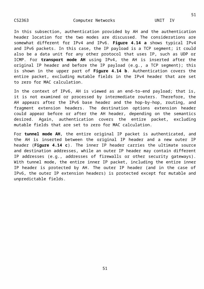
51CS2363 Computer Networks UNIT IV
Application-layer firewalls can understand the traffic flowing through them and allow or deny traffic based on the content. Host-based firewalls designed to block objectionable Web content based on keywords contained in the Web pages are a form of application-layer firewall. You also use application-layer firewalls to inspect packets bound for an internal Web server to ensure the request isn’t really an attack in disguise.
Currently, the ability to inspect a packet’s contents is one of the best ways to distinguish between firewall products. ICF lacks this feature. However, most business-oriented firewalls do include this capability.
ISA Server is also an application-level proxy that’s able to read data within packets for a particular application and perform an action based on a rule set. In addition, ISA Server comes with predefined application filters that inspect each packet and block, redirect, or modify the data within the packet. For instance, you can implement Web-routing rules that tell the ISA Server computer to redirect an HTTP request to a certain internal IIS server, based on the URL in the packet. Another example is the DNS intrusion-detection filter. This filter blocks packets that aren’t valid DNS requests, or that fit common types of DNS attacks. You can invoke application filtering on ISA Server when Web Publishing or Server Publishing is configured.
Logging
Firewalls don’t prevent attacks; they simply reduce the likelihood of a break-in. When you deploy a firewall, you’ll still get just as many attacks as you always did—you just won’t have to worry about them as much. All firewalls provide some capability for logging these attacks for later, manual review. This allows administrators to watch for attacks that are out-of-the-ordinary. It’s also useful for forensics purposes. If an attacker does manage to defeat your firewall, you can refer to the firewall’s log and gather information to determine how the attacker carried out the attack. This log can be useful to law enforcement officials, if they’re involved in a related investigation.
Intrusion Detection
Intrusion detection is an advanced firewall feature, and many firewalls (such as ICF) lack this feature. Intrusion detection systems (IDSs) can identify attack signatures or patterns, generate alarms to alert the operations staff, and cause the routers to terminate the connection with the hostile sources. These systems can also prevent DoS attacks. A DoS attack occurs when a user sends fragments of TCP requests, masked as legitimate TCP requests, or sends requests from a bad IP source. The server can’t handle so many requests and displays a DoS message to legitimate site users. IDSs provide real-time monitoring of network traffic and implement the “prevent, detect, and react” approach to security.
Although IDSs are necessary to meet security requirements for many businesses and some home users, their use has downsides that you should take into account:
IDSs are processing-intensive and can affect the performance of your site.
IDSs are expensive.
IDSs can sometimes mistake normal network traffic for a hostile attack and cause unnecessary alarms. These unnecessary alarms can be so frequent that they cause operational staff to ignore genuine alarms.
There are a number of third-party tools available for intrusion detection. For example, you can use Cisco’s Intrusion Detection System (IDS) or ISS’s RealSecure for real-time network traffic monitoring. IDSs are still in the process of being enhanced and developed.
Antivirus
51
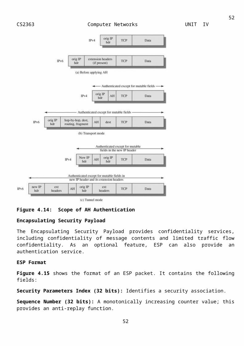
52CS2363 Computer Networks UNIT IV
The term “virus” is used to describe self-replicating computer programs that propagate themselves between files on a computer, and even between computers. Viruses usually, but not always, do something malicious, such as overwrite files or waste your bandwidth by sending copies of themselves to everyone in your address book.
Antivirus capabilities are a feature of some network and host-based firewalls. Network firewalls might inspect all incoming email traffic for virus-infected attachments, and filter them out. Host-based firewalls might change the configuration of the user’s email client so that the email client sends all requests through the host-based firewall.
Firewalls are certainly not the only way to protect yourself from viruses, and if the firewall you choose doesn’t have antivirus features, you’ll need to complement it with antivirus software. The best way to protect your organization against viruses is to use a good-quality commercial antivirus package. These scanners examine the files, folders, mail messages, and Web pages on your computers, looking for the distinctive patterns of viral code. When the scanner detects something that looks like a virus, it quarantines the suspect object and warns you about what it found.
VPNs and Encryption
Port forwarding is sufficient for publishing a Web site through your firewall. However, it’s not sufficient if you want to connect two Internet-connected networks that are both protected by firewalls. For this, you should use a Virtual Private Network (VPN). A VPN is the extension of a private network that encompasses encapsulated, encrypted, and authenticated links across shared or public networks. VPN connections can provide remote access and routed connections to private networks over the Internet. Accessing the corporate network requires administrators to enforce strong authentication to validate identity as well as provide strong encryption to prevent users from communicating data “in the clear.”
VPNs aren’t strictly a firewall feature, and many businesses implement them by using completely separate, dedicated VPN devices. However, network architects generally place network firewalls at the perimeter of the network, just like a VPN. Both firewalls and VPNs are designed to improve network security, so it’s logical that VPN capabilities have become a feature of many firewalls.
If you’re using a Windows 2000 Server or Windows Server 2003 system as your network firewall, you already have VPN capabilities built into the base platform. All recent Windows platforms provide the authentication and encryption infrastructure to enable secure connectivity. With the Windows 2000 Server and Windows Server 2003 built-in VPN server and Windows XP VPN client, organizations can take advantage of a secure standards-based VPN directly “out of the box.” Because Microsoft supports VPN standards such as L2TP/IPSec and smart card authentication, organizations have access to the encryption, authentication, and interoperability that best meet their VPN security needs.
Although organizations often use VPNs to encrypt traffic over the Internet between users and the corporate network, they can also implement encryption between any Windows 2000, Windows Server 2003, and Windows XP machine. Since Microsoft has full standards-based support for the IPSec security extensions, organizations can provide robust encryption of all network traffic, without requiring cumbersome changes to deployed applications, servers, or network hardware.
Host-Based Firewalls
Host-based firewalls are software firewalls installed on each individual system. Depending on the software you choose, a host-based firewall can offer features beyond those of network firewalls, such as protecting your computer from spyware (a component of some free software that tracks your Web browsing habits) and Trojan horses (a program that claims to do one thing, but does another, malicious thing, such as recording
52
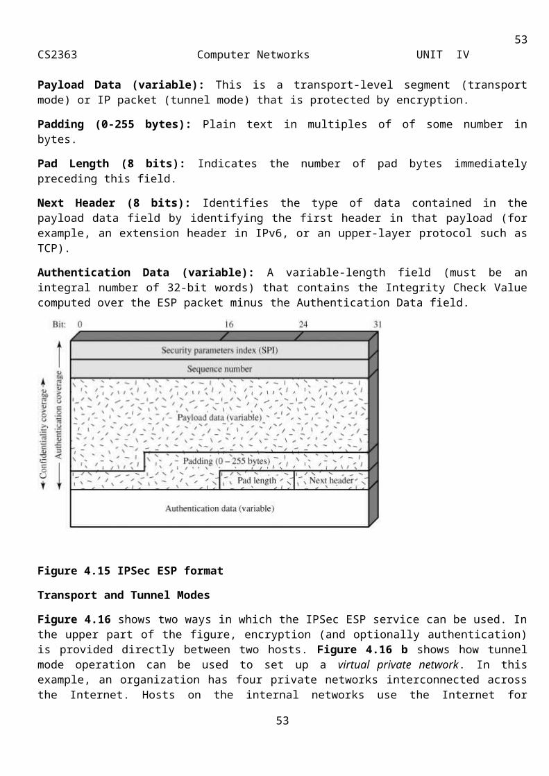
53CS2363 Computer Networks UNIT IV
your passwords). If you travel with a laptop, a host-based firewall is a necessity—you need protection wherever you connect to the Internet, and your hardware firewall can protect you only at home.
Why would you buy third-party firewall software when Windows XP includes ICF for free? ICF is designed to provide basic intrusion prevention, but doesn’t include the rich features of a third-party firewall application. Most third-party firewalls protect you from software that could violate your privacy or allow an attacker to misuse your computer—features not found in ICF. Also, you can install third-party firewall programs on systems that have older versions of Windows. Note that firewall software doesn’t replace antivirus software. You should use both.
Popular host-based firewall products include ZoneAlarm, Tiny Personal Firewall, Agnitum Outpost Firewall, Kerio Personal Firewall, and Internet Security Systems’ BlackICE PC Protection. Most host-based firewall software is available in free or trial versions, so it won’t cost you anything to download these packages and determine whether they meet your needs better than ICF.
Network Firewalls
Network firewalls protect an entire network by guarding the perimeter of that network. Network firewalls forward traffic to and from computers on an internal network, and filter that traffic based on the criteria the administrator has set. Network firewalls come in two flavors: hardware firewalls and software firewalls. Hardware-based network firewalls are generally cheaper than software-based network firewalls, and are the right choice for home users and many small businesses. Software-based network firewalls often have a larger feature set than hardware-based firewalls, and might fit the needs of larger organizations. Software-based firewalls can also run on the same server as other services, such as email and file sharing, allowing small organizations to make better use of existing servers. Network firewalls often include additional features that aren’t necessary for host-based firewalls, as described in the following sections.
Proxy Services
If you have or are planning to have a home or small office network, you’ll have to create a gateway from your firewall to the rest of the network. If you’re implementing a software firewall on a specific computer, this means that you’ll need at least two network cards in that machine. You attach one network card to the public interface (such as a DSL or cable modem), and You attach the other network card to your internal network. You then have to configure the computer to allow traffic on one side of the network to communicate with the other. ICS allows you to do this in both Windows 2000 and Windows XP.
However, at this stage in the game, many small office users decide to buy a dedicated residential gateway (see Figure 5). These units plug directly into the DSL router or cable modem and provide the functionality of a firewall and network hub. You need to configure a residential gateway to act in the stead of the computer running ICS when contacting the ISP. For example, if you had a static IP address, you would have to assign that IP address to the gateway instead of your computer. You could either assign a new IP address to your computer, or, more likely, instruct the computer to ask the gateway for an IP address.
53

54CS2363 Computer Networks UNIT IV
Figure 5: A full-fledged small office network complete with a residential gateway
If a small business is using the 192.168.0.0 network ID for its intranet and its ISP has granted it the public address of w1.x1.y1.z1, then Network Address Translation (NAT) maps all private addresses on 192.168.0.0 to the IP address of w1.x1.y1.z1. If NAT maps multiple private addresses to a single public address, it uses dynamically chosen TCP and UDP ports to distinguish one intranet location from another.
Note: The use of w1.x1.y1.z1 and w2.x2.y2.z2 is intended to represent valid public IP addresses assigned by an ISP.
Figure 6 shows an example of using NAT to transparently connect an intranet to the Internet:
Figure 6: Using NAT to connect an intranet to the Internet
If a private user at 192.168.0.10 uses a Web browser to connect to the Web server at w2.x2.y2.z2, the user’s computer creates an IP packet with the following information:
Destination IP address: w2.x2.y2.z2 Source IP address: 192.168.0.10 Destination port: TCP port 80 Source port: TCP port 5000
The private user’s computer then forwards this packet to the NAT server, which translates the addresses of the outgoing packet to the following:
Destination IP address: w2.x2.y2.z2 Source IP address: w1.x1.y1.z1 Destination port: TCP port 80 Source port: TCP port 1025
The NAT server keeps the mapping of {192.168.0.10, TCP 1025} to {w1.x1.y1.z1, TCP 5000} in a table.The NAT server then sends the translated packet over the Internet to the Web server. The Web server sends the response back to the NAT server. When the NAT server receives the packet, the packet contains the following public address information:
Destination IP address: w1.x1.y1.z1 Source IP address: w2.x2.y2.z2 Destination port: TCP port 1025 Source port: TCP port 80
The NAT server checks its translation table and maps the public addresses to private addresses and forwards the packet to the computer at 192.168.0.10. The forwarded packet contains the following address information:
Destination IP address: 192.168.0.10 Source IP address: w2.x2.y2.z2 Destination port: TCP port 5000
54
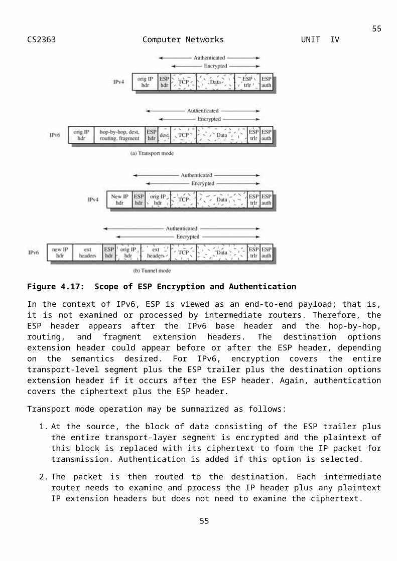
55CS2363 Computer Networks UNIT IV
Source port: TCP port 80For outgoing packets from the NAT server, the NAT server maps the source IP address (a private address) to the ISP allocated address (a public address), and maps the TCP/UDP port numbers to a different TCP/UDP port number.For incoming packets to the NAT server, the NAT server maps the destination IP address (a public address) to the original intranet address (a private address), and maps the TCP/UDP port numbers back to their original TCP/UDP port numbers.
Note: NAT properly translates packets that contain the IP address only in the IP header. NAT might not properly translate packets that contain the IP address within the IP payload.
Reverse Proxy Services
Most proxy servers offer services beyond the standard functionality discussed above. Reverse proxy enables the firewall to provide secure access to an internal Web server (not exposing it to the outside) by redirecting external HTTP (application proxy) requests to a single designated machine. This isn’t suitable for multiserver Web hosting (reverse hosting—described next—takes care of this), but it can be quite valuable when working with a single site.
Reverse hosting allows the firewall to redirect HTTP (application proxy) requests to multiple internal Web servers. One method/way is to provide access to multiple servers as subwebs of one large aggregate Web site or as multiple independent Web servers. More flexible than reverse proxy but equally secure, this method enables you to abstract the physical architecture of your Web sites by mapping multiple servers to a single logical one. Both options allow the firewall to offer caching functionality, which can improve responsiveness.
Server proxy provides the same functionality as reverse proxy and reverse hosting, but unlike these features, it works with protocols other than HTTP to provide secure access from the Internet to internal resources such as internal mail or SQL Server. To an outside user, the proxy server appears to be the mail or SQL Server. Basically, server proxy responds to external requests on behalf of the internal servers, which simply have to run the proxy client that redirects the listen directive on a given port to a proxy server. The security benefit is obvious: Placing servers behind a proxy prevents direct tampering from the outside and fools would-be attackers into thinking that the proxy server is the box containing the information they want.
Reverse proxy can be very useful. For instance, suppose you need to allow a Web server to query an internal database. There are several ways to do this. You could replicate the database to the outside (if it’s not too large), but this puts the contents’ integrity at risk. It might make more sense to move the Web and database servers behind the firewall and use reverse proxy or reverse hosting to get at the site. This option is very secure, although the overhead of running multiple Web servers behind the proxy might tax the proxy’s ability to service Web requests from internal clients.
A third alternative is better yet: Place the Web server in the demilitarized zone (DMZ) and use the server proxy functionality of the firewall to query the database. This option, which Figure 7 (below) shows, provides good security and performance. Before you select any of these options, you should analyze your requirements so that you can balance necessary security against performance/usability.
55
56CS2363 Computer Networks UNIT IV
Figure 7: Firewalls can act as reverse proxies for Web servers.
Firewalls for Small Offices and Home Offices
Firewalls used to be only for large corporate networks—but then again, Internet connections used to be only for large networks, too. Now that high-speed, always-on Internet connectivity is becoming more and more common, so too are attacks against connected computers. Firewalls help protect you against such attacks by screening out many types of malicious traffic. In addition, firewalls can help keep your computer from participating in attacks on others without your knowledge. The good news is that consumer-level firewalls provide good security without requiring that you be a computer security expert.
It used to be true that if you had a computer or two in a small office, the biggest risk you faced was losing data due to a fire, hardware failure, or other catastrophe. Although those risks are still with us, the blessing of always-on, high-speed Internet connectivity has exposed us to new threats, as well as intensifying some older ones. The good news is that, with the right tools, you can do a great deal to safeguard your computer systems against malicious attacks, viruses, and other bad stuff. Some of these tools come included with various versions of Windows. Others come from third-party vendors, such as Symantec, McAfee, and others. It’s not necessarily important that you use a particular brand of tool; it’s more important that you have the right tools, no matter who makes them.
Wireless security
Wireless security is the prevention of unauthorized access or damage to computers using wireless networks. The most common types of wireless security are Wired Equivalent Privacy (WEP) and Wi-Fi Protected Access (WPA). WEP is one of the least secure forms of security. A network that is secured with WEP has been cracked in 3 minutes by the FBI. WEP is an old IEEE 802.11 standard from 1999 which was outdated in 2003 by WPA or Wi-Fi Protected Access. WPA was a quick alternative to improve security over WEP. The current standard is WPA2; some hardware cannot support WPA2 without firmware upgrade or replacement. WPA2 uses an encryption device which encrypts the network with a 256 bit key; the longer key length improves security over WEP.
Many laptop computers have wireless cards pre-installed. The ability to enter a network while mobile has great benefits. However, wireless networking is prone to some security issues. Crackers have found wireless networks relatively easy to break into, and even use wireless technology to crack into wired networks. As a result, it's very important that enterprises define effective wireless security policies that guard against unauthorized access to important resources. Wireless Intrusion Prevention Systems (WIPS) or Wireless Intrusion Detection Systems (WIDS) are commonly used to enforce wireless security policies.
The risks to users of wireless technology have increased as the service has become more popular. There were relatively few dangers when wireless technology was first introduced. Crackers had not yet had time to latch on to the new technology and wireless was not commonly found in the work place. However, there are a great number of security risks associated with the current wireless protocols and encryption methods, and in the
56
57CS2363 Computer Networks UNIT IV
carelessness and ignorance that exists at the user and corporate IT level. Cracking methods have become much more sophisticated and innovative with wireless. Cracking has also become much easier and more accessible with easy-to-use Windows or Linux-based tools being made available on the web at no charge.Some organizations that have no wireless access points installed do not feel that they need to address wireless security concerns. In-Stat MDR and META Group have estimated that 95% of all corporate laptop computers that were planned to be purchased in 2005 were equipped with wireless. Issues can arise in a supposedly non-wireless organization when a wireless laptop is plugged into the corporate network. A cracker could sit out in the parking lot and gather info from it through laptops and/or other devices as handhelds, or even break in through this wireless card-equipped laptop and gain access to the wired network.Modes of unauthorized accessThe modes of unauthorised access to links, to functions and to data is as variable as the respective entities make use of program code. There does not exist a full scope model of such threat. To some extent the prevention relies on known modes and methods of attack and relevant methods for suppression of the applied methods. However, each new mode of operation will create new options of threatening. Hence prevention requires a steady drive for improvement. The described modes of attack are just a snapshot of typical methods and scenarios where to apply.Accidental associationViolation of the security perimeter of a corporate network can come from a number of different methods and intents. One of these methods is referred to as “accidental association”. When a user turns on a computer and it latches on to a wireless access point from a neighboring company’s overlapping network, the user may not even know that this has occurred. However, it is a security breach in that proprietary company information is exposed and now there could exist a link from one company to the other. This is especially true if the laptop is also hooked to a wired network.Accidental association is a case of wireless vulnerability called as "mis-association". Mis-association can be accidental, deliberate (for example, done to bypass corporate firewall) or it can result from deliberate attempts on wireless clients to lure them into connecting to attacker's APs.
Malicious association
“Malicious associations” are when wireless devices can be actively made by attackers to connect to a company network through their cracking laptop instead of a company access point (AP). These types of laptops are known as “soft APs” and are created when a cyber criminal runs some software that makes his/her wireless network card look like a legitimate access point. Once the thief has gained access, he/she can steal passwords, launch attacks on the wired network, or plant trojans. Since wireless networks operate at the Layer 2 level, Layer 3 protections such as network authentication and virtual private networks (VPNs) offer no barrier. Wireless 802.1x authentications do help with some protection but are still vulnerable to cracking. The idea behind this type of attack may not be to break into a VPN or other security measures. Most likely the criminal is just trying to take over the client at the Layer 2 level.
Ad-hoc networksAd-hoc networks can pose a security threat. Ad-hoc networks are defined as peer-to-peer networks between wireless computers that do not have an access point in between them. While these types of networks usually have little protection, encryption methods can be used to provide security.The security hole provided by Ad-hoc networking is not the Ad-hoc network itself but the bridge it provides into other networks, usually in the corporate environment, and the unfortunate default settings in most versions of Microsoft Windows to have this feature turned on unless explicitly disabled. Thus the user may not even know they have an unsecured Ad-hoc network in operation on their computer. If they are also using a wired or wireless infrastructure network at the same time, they are providing a bridge to the secured organizational network through the unsecured Ad-hoc connection. Bridging is in two forms. A direct bridge, which requires the user actually configure a bridge between the two connections and is thus unlikely to be
57

58CS2363 Computer Networks UNIT IV
initiated unless explicitly desired, and an indirect bridge which is the shared resources on the user computer. The indirect bridge provides two security hazards. The first is that critical organizational data obtained via the secured network may be on the user's end node computer drive and thus exposed to discovery via the unsecured Ad-hoc network. The second is that a computer virus or otherwise undesirable code may be placed on the user's computer via the unsecured Ad-hoc connection and thus has a route to the organizational secured network. In this case, the person placing the malicious code need not "crack" the passwords to the organizational network, the legitimate user has provided access via a normal and routine log-in. The malfactor simply needs to place the malicious code on the unsuspecting user's end node system via the open (unsecured) Ad-hoc networks.Non-traditional networksNon-traditional networks such as personal network Bluetooth devices are not safe from cracking and should be regarded as a security risk. Even barcode readers, handheld PDAs, and wireless printers and copiers should be secured. These non-traditional networks can be easily overlooked by IT personnel who have narrowly focused on laptops and access points.
Identity theft (MAC spoofing)Identity theft (or MAC spoofing) occurs when a cracker is able to listen in on network traffic and identify the MAC address of a computer with network privileges. Most wireless systems allow some kind of MAC filtering to allow only authorized computers with specific MAC IDs to gain access and utilize the network. However, programs exist that have network “sniffing” capabilities. Combine these programs with other software that allow a computer to pretend it has any MAC address that the cracker desires, and the cracker can easily get around that hurdle.
MAC filtering is effective only for small residential (SOHO) networks, since it provides protection only when the wireless device is "off the air". Any 802.11 device "on the air" freely transmits its unencrypted MAC address in its 802.11 headers, and it requires no special equipment or software to detect it. Anyone with an 802.11 receiver (laptop and wireless adapter) and a freeware wireless packet analyzer can obtain the MAC address of any transmitting 802.11 within range. In an organizational environment, where most wireless devices are "on the air" throughout the active working shift, MAC filtering provides only a false sense of security since it prevents only "casual" or unintended connections to the organizational infrastructure and does nothing to prevent a directed attack.
Man-in-the-middle attacksA man-in-the-middle attacker entices computers to log into a computer which is set up as a soft AP (Access Point). Once this is done, the hacker connects to a real access point through another wireless card offering a steady flow of traffic through the transparent hacking computer to the real network. The hacker can then sniff the traffic. One type of man-in-the-middle attack relies on security faults in challenge and handshake protocols to execute a “de-authentication attack”. This attack forces AP-connected computers to drop their connections and reconnect with the cracker’s soft AP(disconnects the user from the modem so they have to connect again using their password which you can extract from the recording of the event). Man-in-the-middle attacks are enhanced by software such as LANjack and AirJack which automate multiple steps of the process, meaning what once required some skill can now be done by script kiddies. Hotspots are particularly vulnerable to any attack since there is little to no security on these networks.
Denial of serviceA Denial-of-Service attack (DoS) occurs when an attacker continually bombards a targeted AP (Access Point) or network with bogus requests, premature successful connection messages, failure messages, and/or other commands. These cause legitimate users to not be able to get on the network and may even cause the network to crash. These attacks rely on the abuse of protocols such as the Extensible Authentication Protocol (EAP).
58
59CS2363 Computer Networks UNIT IV
The DoS attack in itself does little to expose organizational data to a malicious attacker, since the interruption of the network prevents the flow of data and actually indirectly protects data by preventing it from being transmitted. The usual reason for performing a DoS attack is to observe the recovery of the wireless network, during which all of the initial handshake codes are re-transmitted by all devices, providing an opportunity for the malicious attacker to record these codes and use various "cracking" tools to analyze security weaknesses and exploit them to gain unauthorized access to the system. This works best on weakly encrypted systems such as WEP, where there are a number of tools available which can launch a dictionary style attack of "possibly accepted" security keys based on the "model" security key captured during the network recovery.Network injectionIn a network injection attack, a cracker can make use of access points that are exposed to non-filtered network traffic, specifically broadcasting network traffic such as “Spanning Tree” (802.1D), OSPF, RIP, and HSRP. The cracker injects bogus networking re-configuration commands that affect routers, switches, and intelligent hubs. A whole network can be brought down in this manner and require rebooting or even reprogramming of all intelligent networking devices.
Caffe Latte attackThe Caffe Latte attack is another way to defeat WEP. It is not necessary for the attacker to be in the area of the network using this exploit. By using a process that targets the Windows wireless stack, it is possible to obtain the WEP key from a remote client. By sending a flood of encrypted ARP requests, the assailant takes advantage of the shared key authentication and the message modification flaws in 802.11 WEP. The attacker uses the ARP responses to obtain the WEP key in less than 6 minutes.
Wireless intrusion prevention conceptsThere are three principal ways to secure a wireless network.
For closed networks (like home users and organizations) the most common way is to configure access restrictions in the access points. Those restrictions may include encryption and checks on MAC address. Another option is to disable ESSID broadcasting, making the access point difficult for outsiders to detect. Wireless Intrusion Prevention Systems can be used to provide wireless LAN security in this network model.
For commercial providers, hotspots, and large organizations, the preferred solution is often to have an open and unencrypted, but completely isolated wireless network. The users will at first have no access to the Internet nor to any local network resources. Commercial providers usually forward all web traffic to a captive portal which provides for payment and/or authorization. Another solution is to require the users to connect securely to a privileged network using VPN.
Wireless networks are less secure than wired ones; in many offices intruders can easily visit and hook up their own computer to the wired network without problems, gaining access to the network, and it's also often possible for remote intruders to gain access to the network through backdoors like Back Orifice. One general solution may be end-to-end encryption, with independent authentication on all resources that shouldn't be available to the public.
There is no ready designed system to prevent from fraudulent usage of wireless communication or to protect data and functions with wirelessly communicating computers and other entities. However there is a system of qualifying the taken measures as a whole according to a common understanding what shall be seen as state of the art. The system of qualifying is an international consensus as specified in ISO/IEC 15408.
59