Embed Size (px)
Citation preview

USDAForest Service
WILDLAND FIREENGINE GUIDE
United StatesDepartment ofAgriculture
Forest Service
Technology &DevelopmentProgram
5100—Fire ManagementOctober 20000051 1203—SDTDC
FOREST SERVICE
DEP A R T MENT OF AGRICUL T U R
E
USDAForest Service
WILDLAND FIREENGINE GUIDE
Information contained in this document has been developed for theguidance of employees of the Forest Service, USDA, its contractors,and cooperating Federal and state agencies. The Department ofAgriculture assumes no responsibility for the interpretation or use of thisinformation by other than its own employees. The use of trade, firm, orcorporation names is for the information and convenience of the reader.Such use does not constitute an official evalution, conclusion,recommendation, endorsement, or approval of any product or service tothe exclusion of others that may be suitable.
The U.S. Department of Agriculture (USDA) prohibits discrimination inall its programs and activities on the basis of race, color, national origin,sex, religion, age, disability, political beliefs, sexual orientation, or maritalor family status. (Not all prohibited bases apply to all programs.) Personswith disabilities who require alternative means for communication ofprogram information (Braille, large print, audiotape, etc,) should contactUSDA’s TARGET Center at (202)720-2600 (voice and TDD).
To file a complaint of discrimination, write USDA, Director, Office of CivilRights, Room 326-W, Whitten Building, 1400 Independence Avenue,SW, Washington, D.C. 20250-9410 or call (202) 720-5964 (voice andTDD). USDA is an equal opportunity provider and employer.
USDA Forest ServiceSan Dimas Technology & Development Center
San Dimas, California
October 2000
National Wildland Fire Engine Committee (NWFEC))The NWFEC, formed in 1997, is staffed by experts in the fields of engineering, fire, fleet, and safety. The committeeprovides the U. S. Department of Agriculture (USDA) Forest Service (FS) with flexible engine standard guidelinesto help meet unique regional needs. The guidelines help the agency balance cost effectiveness with performance,focus on the user’s operational needs, and achieve the highest degree of safety possible.
The NWFES established a charter, approved by the Director of Fire and Aviation Management, to provide thefollowing direction:
1. Direct the development of mission standards that meet Forest Service mobile fire equipment needs.
2. Facilitate technology transfer among regions by selection of the “best of the best” of existing designsand specifications.
3. Facilitate an exchange of ideas with the National Wildland Coordinating Group (NWCG) Fire EquipmentWorking Team (FEWT).
4. Oversight and direction provided by the San Dimas Technology and Development Center (SDTDC).
To accomplish the charter, the committee established the following objectives for the Forest Service WildlandFire Engine project:
1. Develop a set of standards against which all wildland fire engines will be evaluated.
2. Work with other national organizations on standards which set requirements for the equipmentperformance and safety of wildland fire engines.
3. Identify commercially available fire engines, or packages, which can be used in wildland fire.
4. Work with manufacturers to influence changes that will result in better and safer products.
5. Coordinate with General Services Administration (GSA) and vendors to place products on schedule.
6. Publish a guide to provide information on the products tested, considerations needed when selectinga vehicle/slip-on unit combination, options available for each product, product comparison, and otherpertinent data.
The current NWFEC members are:Mike AriasUSDA FS Regional Office (Region 5)1323 Club DriveVallejo, CA 94592(707) 562-8847
Carl BambargerSan Dimas Technology & Development Center444 East Bonita Ave.San Dimas, CA 91773(909) 599-1267 ext. 234FAX (909) 591-2309
Willie BoyerUSDA FS Regional Office (Region 2)740 Simms St.Golden, CO 80401(303) 275-5792FAX (303) 275-5192
Howard Carlson (Region 3)Apache-Sitgreaves National ForestP.O. Box 760Springerville, AZ 85938(520) 333-4372FAX (520) 333-4182
Mark A. Clere (Region 8)Ocala National ForestLake George Ranger District17147 E. Hwy. 40Silver Springs, FL 34488(352) 625-2520
Gordon Foster (Region 6)Siskiyou National ForestP.O. Box 440Grants Pass, OR 97521(541) 471-6540FAX (541) 471-6512
Kathryn KirkpatrickLos Padres National Forest3333 Casitas Pass Rd.Ventura, CA 93001(805) 649-3861FAX (805) 649-2340
Dan W. McKenzieSan Dimas Technology & Development Center444 East Bonita Ave.San Dimas, CA 91773(909) 599-1267, ext. 243FAX (909) 592-2309
iii

Steven MorefieldBurns Ranger DistrictBLM OregonHC-74 Box 12870Burns, OR 97738(541) 573-4435
Ralph TaylorSan Dimas Technology & Development Center444 East Bonita Ave.San Dimas, CA 91773(909) 599-1267 ext. 234FAX (909) 591-2309
Phillip Shafer (Region 5)Plumas National ForestMt. Hough Ranger District39696 Hwy 70Quincy, CA 95971(530) 283-0555FAX (530) 284-6211
Jon TuckerUSDA FS Regional Office (Region 4)324 25th St.Ogden, UT 84401(801) 625-5565FAX (801) 625-5359
Roberta Whitlock (Region 1)USDA FS Aerial Fire DepotP.O. Box 6 AirportMissoula, MT 59802(406) 329-4956FAX (406) 329-4955
iv

TABLE OF CONTENTS
INTRODUCTIONChoosing an Engine to Purchase ...................................................................................................... vii
Developing a New Wildland Fire Engine ........................................................................................... vii
CHAPTER 1—NWFEC WILDLAND FIRE ENGINE CLASSESNWFEC Wildland Fire Engine Classes .............................................................................................. 1NWCG Engine Types ......................................................................................................................... 3
CHAPTER 2—STANDARD GUIDELINES FOR FOREST SERVICE WILDLAND FIRE ENGINESCriteria for Standard Guidelines for Forest Service Wildland Fire Engines........................................ 5
CHAPTER 3—EVALUATION RESULTS AND DESCRIPTIONS OF WILDLAND FIRE ENGINESTESTED
Evaluation Results
Class LP Wildland Fire Engines .............................................................................................. 21
Class A Wildland Fire Engines ................................................................................................ 26
Class B Wildland Fire Engines ................................................................................................ 31
Class C Wildland Fire Engines ................................................................................................ 36
Class D Wildland Fire Engines ................................................................................................ 41
Descriptions of Wildland Fire Engines Tested
Class LP Wildland Fire Engines .............................................................................................. 47Class A Wildland Fire Engines ................................................................................................ 48
Class B Wildland Fire Engines ................................................................................................ 49
Class C Wildland Fire Engines ................................................................................................ 52
Class D Wildland Fire Engines ................................................................................................ 53
APPENDIX AAdditional Information on Major Components and Systems ............................................................ 57
Additional Resources for Design and Use Information..................................................................... 61
APPENDIX BVendors on GSA Contract ................................................................................................................ 63
GLOSSARY .................................................................................................................................... 64
BIBLIOGRAPHY ............................................................................................................................. 66
v

NWFEC and SDTDC developed this first edition ofthe Forest Service Wildland Fire Engine Guide. Thispublication is designed to provide fire managementpersonnel with an easy to use reference to assist withthe purchase of fire apparatus and support vehiclesthat meet Forest Service Standard Guidelines.
Field users are encouraged to invite industryparticipation for wildland fire engines in which theyhave interest. This guide, on the SDTDC web site,http://fsweb.stdcd.wo.fs.fed.us, will be updated asinspection and performance evaluations arecompleted.
This guide has three chapters:Chapter 1, NWFEC Wildland Fire Engine Classes,defines LP, A, B, C, and D engine classes basedon fire behavior and the corresponding suppressionequipment performance requirements.
Chapter 2, Standard Guidelines for Forest ServiceWildland Fire Engine, presents standards, alongwith supporting rationale on design characteristicsdetermined to be essential to wildland fire engines.
Chapter 3, Evaluation Results and Descriptions ofWildland Fire Engines Tested, provides the resultsof tests performed at SDCTC and brief descriptionswith photographs of each apparatus tested.
Appendix A provides the user with information on pastexperiences, design considerations, and wildlandengine performance issues that are important in thedesign of new fire engines.
Choosing an Engine to PurchaseStep 1: To begin using this guide, identify thewildland fire engine class of interest using theexplanation of engine classes in Chapter 1. Reviewthe criteria to identify those fire enginecharacteristics that correspond with the needs foryour geographic area.
Step 2: With the fire engine class identified,review table 3, NWFEC Standard Guidelines forForest Service Wildland Fire Engines.The tablesummarizes the design, performance, safety,documentation, standardization, and operationalcriteria developed by the NWFES. The tablepresents the criteria as required (R), desired (D),and optional (O) for each NWFEC fire engine class.Criteria that are identified as required are theminimum national standards for equipment and
performance to be included on FS wildland fireengines. The user is cautioned to implement all ofthe required criteria; they were developed to reflectsafety and national mobility as well as localconsiderations.
Step 3: Next, examine Chapter 3, EvaluationResults and Descriptions of Wildland Fire EnginesTested. The results of engines tested to thestandard guidelines at SDTDC identify thosewildland engines—in the class of interest—thatprovide the desired suppression characteristics.
Step 4: With the fire engine of choice identified,the user should then contact their fleet equipmentmanager or the appropriate acquisitionrepresentative.
The GSA has established contract schedules for manyof the commercially available fire engines, whichmakes purchasing quick and easy. The FederalAcquisition Regulation (FAR) contains specificlanguage regarding the simplified acquisition processfor items that are contained on GSA contractschedules. Items on GSA contract schedules arealready determined to have a fair and reasonable price,and should not require additional efforts by the orderingoffice. (See the FAR. Using schedule 8.404 (a).) Thissection of the FAR allows the purchase of items onschedules without seeking further competition.
Appendix B provides a web site to GSA purchasingsystem vendors. The user is cautioned that GSA isnot obligated to verify that the fire equipment meetsFS standards. Using the USDA Forest ServiceWildland Fire Engine Guide in conjunction with theGSA schedule of vendors will help ensure that wildlandfire vehicles and equipment match approved FSdesign, performance, and safety standards aspresented within this guide.
Developing a New Wildland Fire EngineReview appendix A for additional information on designand performance information. Resources for designinformation are available from the groups identifiedunder Additional Resources for Design and UseInformation.
Develop a bid package for the demonstration/prototypeunit. Include in the bid package the requirement tohave the wildland engine evaluated to the all of criterialisted for the class.
INTRODUCTION
vii

When the newly developed fire engine is complete—and the user is satisfied with its performance—the unitwill be evaluated against the fire engine criteria bySDTDC. The manufacturer pays the cost of theevaluation. The results of the evaluation will bepublished in the next revision of this guide and addedto the appropriate table on the SDTDC web site foruse by all FS units. Additionally, the user should pursueestablishing GSA pricing for the unit.
viii

1
CHAPTER 1
The committee’s approach in developing wildland fireengine classes was based on fire behavior and itsassociated suppression equipment needs; increasingfire activity requires greater suppression ability. Thecommittee developed the following fire engine classmission definitions based on their combined fireexperience and fire engine capability needs for criticalparameters: engine capability, pump capacity, tanksize, crew size in relationship to fire behavior, fireintensity, burning index, and rate of spread. While otherfire engine typing or classes exist, their purpose isdifferent than the focus of the committee. Note: Asused in this guide, the terms wildland fire engine (orvariants thereof) include the light patrol and slip-onfire packages.
Class LPMission: Wildland fire engine will combat verylow intensity and low rate of spread fires. Enginewill support the prescribed fire.
Equipment Selection: Gross vehicle weightrating (GVWR), tank size, and pump parameterswere selected to meet the needs of a light, fastresponse vehicle in order to satisfy the mission.
Operational Concept: Fire suppressionequipment will be easy to operate and requireno particular certification for operation. Expectlittle or minimal training to operate engine. Vehiclerequires only basic drivers license. A crew of 1or 2 people is needed.
Class AMission: Wildland fire engine will combat lowintensity and low rate of spread fires. Engine willsupport the prescribed fire.
Equipment Selection: GVWR, tank size, andpump parameters were selected to meet theneeds of a light, fast response engine in order tosatisfy the mission.
Operational Concept: Fire suppressionequipment will be easy to operate and requiresno particular certification for operation. Expectlittle or minimal training to operate engine. Vehiclerequires only a basic drivers license. A crew of 1or 2 people is needed.
Class BMission: Wildland fire engine will combat fireswith low to moderate intensity with low tomoderate rates of spread. Engine will support theprescribed fire.
Equipment Selection: GVWR, tank size, andpump parameters were selected to meet theneeds of a fast response engine in order to satisfythe mission.
Operational Concept: Vehicle is fast response,good power to weight ratio, and maneuverable.Pump provides moderate lift capability, and thetank supports multi-mission needs. Crews will becertified and require a low number of traininghours for engine operation. A crew of 2 to 3 peopleis required.
Class CMission: Wildland fire engine will combatmoderate to high intensity fires with moderate torapid rates of spread. Engine will support theprescribed fire.
Equipment Selection: GVWR, tank size, andpump parameters were selected to meet theneeds of a fast response engine in order to satisfythe mission.
Operational Concept: Vehicle is fast response,good power to weight ratio, and maneuverable.Pump requires moderate training hours forengine operation. A crew of 3 to 5 people isrequired.
Class DMission: Combat high intensity fires withmoderate to rapid rates of spread. Engine willsupport the prescribed fire. Supplies water toelevated locations that support numerous crews.
Equipment Selection: GVWR, tank size, andpump parameters were selected in order tosatisfy the needs of a fast response engine tomeet the mission.
Operational Concept: Vehicle is fast response,good power to weight ratio, and maneuverable.Pump provides high lift capability. Crews will becertified and require moderate training for engineoperation. A crew of 3 to 5 people is required.
NWFEC WILDLAND FIRE ENGINE CLASSES

2
CHAPTER 1
To meet these definitions, the committee established the minimum values for pump capacity (bench rating ofgpm and psi), chassis size, tank capacity, and crew size. Table 1 summarizes the NWFEC Wildland Fire EngineClasses to meet the mission definitions.
Table 1—Engine classes (engine capability) LP, A, B, C, and D.
Wildland Engine Class (engine capability) LP, A, B, C, and D
Class LP A B C D
Pump (bench rating)GPM 8 20 50 90 200@pressure (psi) 65 100 200 300 300
Tank Size Minimum 50 50 200 300 500Crew Size 1–2 1–2 2–3 3–5 3–5
Figure 1 is a graphical presentation of the committee’s concept of increasing fire behavior and increasingsuppression capacity of wildland engines. While each class of wildland engine is intended for suppression in aspecific fire behavior region, larger capacity wildland engines are capable of meeting the missions of lessercapacity. The extended dashed lines represent this concept from the corners of suppression design region forthe larger class fire engines.
Figure 1—Wildland fire engine capability: pump capacity, tank size, crew size in relation to fire behavior—fire intensity, burning index, and rate of spread.
Class D
Class C
Class B
Class A
Class LP
GPM: 200 @ 300 psiGVW: 28k—32kTank: 500 gal. min.Crew: 3—5
GPM: 90 @ 300 psiGVW: 15k—28kTank: 300 gal. min.Crew: 3—5
GPM: 50 @ 200 psiGVW: 12k—28kTank: 200 gal. min.Crew: 2—3
GPM: 20 @ 100 psiGVW: 8600Tank: 50 gal. min.Crew: 1—2
GPM: 8 @ 65 psiTank: 50 gal. min.Crew: 1—2
Increasing Burning Index
Incr
easi
ng
Rat
e o
f S
pee
d

3
CHAPTER 1
Figure 2 is provided to illustrate the relationship between the NWCG Engine Typing System and the NWFECWildland Fire Engine Classes. Direct comparison is difficult because of the multiple parameters of each system.Therefore, pump capability is the predominate measure for the comparison below.
NWCG NWFECTyping Wildland FireSystem Engine Classes
Figure 2—Engine types and engine class comparisons.
NWCG Engine TypesUsing the Fire Equipment Working Team (FEWT) and the National Fire Protection Association (NFPA), theNational Wildfire Coordinating Group (NWCG) categorizes information on fire engines into logical groups andprovides common options often requested by fire managers. The Incident Command System (ICS) uses thisengine type system based on the equipment. The NWFEC Wildland Fire Engine Classes used throughout thisguide (LP, A, B, C, and D) are based on its mission and engine capability in relation to fire behavior. Table 2shows NWCG minimum requirements for engine and water tender resource types.
Table 2—NWCG Engine Types—Minimum Requirements.
STRUCTURE WILDLANDENGINES ENGINES
Components 1 2 3 4 5 6 7Pump Rating
minimum flow (gpm) 1000+ 250+ 150 50 50 30 10
at rated pressure (psi) 150 150 250 100 100 100 100
Tank Capacity Range (gal) 400+ 400+ 500+ 750+ 400–750 150–400 50–200
Hose (feet)
2-1/2 inch 1200 1000 ~ ~ ~ ~ ~
1-1/2 inch 400 500 500 300 300 300 ~
1 inch ~ ~ 500 300 300 300 200
Ladders (ft) 48 48 ~ ~ ~ ~ ~
Master Stream (GPM) 500 ~ ~ ~ ~ ~ ~
Personnel (minimum) 4 3 2 2 2 2 2
Type 7Engine
Type 6Engine
Type 4Engine
Type 3Engine
Type 5Engine
LP Class
A Class
B Class
C Class
D Class

4
CHAPTER 1
Wildland engine types are described below.
Type 3—An engine that features a high-volume andhigh-pressure pump. The GVWR is generally greaterthan 20,000 pounds.
Type 4—A heavy engine with large water capacity.Chassis GVWR is in excess of 26,000 pounds.
Type 5—Normally an initial attack engine on a mediumduty chassis. GVWR of the chassis is in the 16,000 to26,000 pound range.
Type 6—Normally an initial attack engine on a mediumduty chassis. GVWR of the chassis is in the 9,000 to16,000 pound range.
Type 7—A light duty vehicle usually on a 6,500 to10,000 pound GVWR chassis. The vehicle has a smallpump and is a multipurpose unit used for patrol, mopup, or initial attack.

5
CHAPTER 2
STANDARD GUIDELINES FOR FOREST SERVICE WILDLAND FIRE ENGINES
Criteria for Standard Guidelines for Forest Service Wildland Fire EnginesNWFEC has developed this set of performance and design criteria for Forest Service wildland fire engines.Engines available in each class have been tested against the NWFEC standard set of performance and designcriteria at SDTDC. The criteria are written in “shall” compliance form. The NWFEC Standard Guidelines areshown in table 3. This table provides a matrix defining which criteria are required for each class of wildland fireengine.

6
CH
AP
TE
R 2
Table 3—Criteria for Standard Guidelines for Forest Service Wildland Fire Engines.

7
CH
AP
TE
R 2
Table 3—Criteria for Standard Guidelines for Forest Service Wildland Fire Engines (continued).

8
CH
AP
TE
R 2
Table 3—Criteria for Standard Guidelines for Forest Service Wildland Fire Engines (continued).

9
CH
AP
TE
R 2
Table 3—Criteria for Standard Guidelines for Forest Service Wildland Fire Engines (continued).

10
CH
AP
TE
R 2
Table 3—Criteria for Standard Guidelines for Forest Service Wildland Fire Engines (continued).

11
CH
AP
TE
R 2
Table 3—Criteria for Standard Guidelines for Forest Service Wildland Fire Engines (continued).
12
CHAPTER 2
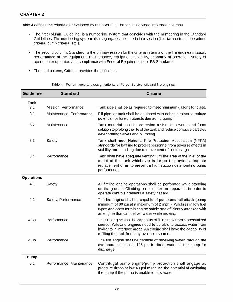
Table 4 defines the criteria as developed by the NWFEC. The table is divided into three columns.
• The first column, Guideline, is a numbering system that coincides with the numbering in the StandardGuidelines. The numbering system also segregates the criteria into section (i.e., tank criteria, operationscriteria, pump criteria, etc.).
• The second column, Standard, is the primary reason for the criteria in terms of the fire engines mission,performance of the equipment, maintenance, equipment reliability, economy of operation, safety ofoperation or operator, and compliance with Federal Requirements or FS Standards.
• The third column, Criteria, provides the definition.
Table 4—Performance and design criteria for Forest Service wildland fire engines.
Guideline Standard Criteria
Tank3.1 Mission, Performance Tank size shall be as required to meet minimum gallons for class.
3.1 Maintenance, Performance Fill pipe for tank shall be equipped with debris strainer to reducepotential for foreign objects damaging pump.
3.2 Maintenance Tank material shall be corrosion resistant to water and foamsolution to prolong the life of the tank and reduce corrosive particlesdeteriorating valves and plumbing.
3.3 Safety Tank shall meet National Fire Protection Association (NFPA)standards for baffling to protect personnel from adverse affects instability and handling due to movement of liquid cargo.
3.4 Performance Tank shall have adequate venting; 1/4 the area of the inlet or theoutlet of the tank whichever is larger to provide adequatereplacement of air to prevent a high suction deteriorating pumpperformance.
Operations
4.1 Safety All fireline engine operations shall be performed while standingon the ground. Climbing on or under an apparatus in order tooperate controls presents a safety hazard.
4.2 Safety, Performance The fire engine shall be capable of pump and roll attack (pumpminimum of 80 psi at a maximum of 2 mph.) Wildfires in low fueltypes and open terrain can be safely and efficiently attacked withan engine that can deliver water while moving.
4.3a Performance The fire engine shall be capability of filling tank from a pressurizedsource. Wildland engines need to be able to access water fromhydrants in interface areas. An engine shall have the capability ofrefilling the tank from any available source.
4.3b Performance The fire engine shall be capable of receiving water, through theoverboard suction at 125 psi to direct water to the pump fordischarge.
Pump
5.1 Performance, Maintenance Centrifugal pump engine/pump protection shall engage aspressure drops below 40 psi to reduce the potential of cavitatingthe pump if the pump is unable to flow water.

13
CHAPTER 2
Guideline Standard Criteria
5.1a Performance, Maintenance Engine protection for the auxiliary engine shall shut it down.
5.1b Performance, Maintenance Engine protection for the power take off (PTO) shall return theengine to idle.
5.2a Environmental Auxiliary engine shall be equipped with emission controls.
5.2b Performance Auxiliary engine shall be equipped with electric starter. Thisavoids relying on a pull cord starter. Electric start provides faster,more continuous rpm to quickly and easily start the engine.The continuous rpm can prevent engine stalls resulting fromflooding or carbon buildup on spark plugs.
5.2c Safety, FS Standard Auxiliary engine shall have a spark arrester qualified inaccordance with Forest Service Standard 5200-1. Auxiliaryengines can throw sparks that could cause fires unless theyare equipped with the proper spark arrester.
5.3 Maintenance A coolant line shall be provided to circulate cool water from thetank to the pump to provide overheating protection of thecentrifugal pump and avoid cavitation.
Priming
6.1 Performance The engine shall be capable of priming and pumping waterthrough 24 ft of suction hose with10 ft of vertical lift. This criteriaestablishes a minimum lift capability for the priming system.
6.2 Performance The engine shall be capable of priming and pumping waterthrough 24 ft of suction hose with 17 ft of vertical lift. This criteriaestablishes a maximum lift capability for the priming system.
6.3 Performance The primer shall develop 17 inches of Hg with no greater thana 10-inch loss in 5 minutes. This criteria establishes a minimumvacuum capability for the priming system.
6.4 Performance The pump shall be capable of being primed with the enginerunning. In cases where prime may be lost, this allows theoperator to safely re-establish a prime without shutting downthe engine, reducing the time required to again provide waterto the hose lay.
6.5 Mission Only environmentally safe fluids, water preferred, shall bedischarged on the ground when priming. This is to avoidcontaminating the environment with the oil that some primersuse. Water-only discharge primers eliminate primer servicingand associated equipment.
6.6 Performance The priming line shall have a check valve or equivalent.
Plumbing
7.1 Performance Plumbing layout shall be as described in the “Water HandlingEquipment Guide.”
7.2 Maintenance All water flow shall pass through a suction strainer prior toentering the pump to avoid debris entering and damaging thepump. It must be easily accessible in order to be cleaned.

14
CHAPTER 2
Guideline Standard Criteria
7.3 Performance The suction plumbing section should not have “humps.” Suctionplumbing that has humps retain air bubbles after a prime isestablished and pumping has started. These bubbles can bedrawn into the pump, causing a loss of prime.
7.4 Safety If there are humps in the suction plumbing, priming taps at boththe top of the hump and the inlet of the pump shall be used.Without priming taps at top of the hump, priming may be slowor impossible.
7.5 Maintenance The entire plumbing system and pump shall be capable of beingdrained without emptying the tank. This allows for winterizationof the system.
7.6 Performance, Economy The piping size shall match the designed engine dischargeperformance. If the piping, particularly the suction but also thepressure piping, are too small, the performance of the enginewill be degraded. Too large of piping is costly and addsunnecessary weight.
7.7 Mission Newly purchased fire engines must have the proper connectionsso they will match the existing equipment (hoses, etc.) that havebeen standardized in the FS fire caches. This avoids the needfor adapters and provides for interchangeability.
7.8 FS Standard Fire hose connections on engines shall have these threads:3/4-inch, 1-1/2 inch, 2-1/2, and 4 inch are NH, and 1and 2 inchare NPSH. Newly purchased fire engines must have the properconnections so they will match the existing equipment (hoses,etc.) that have been standardized in the FS fire caches. Thisavoids the need for adapters and provides for interchangeability.
Valves
8 FS Standard, Performance The following valve nomenclature shall be used on ForestService Wildland Fire Engines.
8.1 FS Standard, Performance Valve No. 1, Tank to Pump, allows the isolation of the tank andallows for drafting.
8.2 FS Standard, Performance Valve No. 2, Pump to Tank, allows for refilling of the tank throughthe plumbing, without using external hoses. Allows for refillingof the tank while pumping a hose lay.
8.3 FS Standard, Performance Valve No. 3, Overboard Discharge, allows control of the outputof the pump or isolating hose lays.
8.4 FS Standard, Performance Valve No. 4, Hose Reel or Basket Discharge, allows for isolationof the hose reel or basket discharge.
8.5 FS Standard Valve No. 5, Dedicated Engine Protection Discharge, no longerin wide use.
8.6 FS Standard Valve No. 6, Pump to Primer, allows for isolation of the primer.In cases of filling the tank from a pressurized source, it will stopwater from being discharged out through the primer.
8.7 Safety Valve No. 7, Pressure Relief Valve for positive displacementpumps, protects the equipment from over pressurizing the pump.
8.8 FS Standard, Mission Valve No. 8, Overboard Suction, controls pump intake from draftor pressurized source.

15
CHAPTER 2
Guideline Standard Criteria
8.9 FS Standard Valve No. 9, Reserve Supply from Tank to Pump, no longer inwide use. Provides for a reserve amount of water in the tank.
8.10 FS Standard Valve No. 10, In Tank Shutoff, no longer in wide use.
8.11 FS Standard, Maintenance Valve No. 11, Pump and Plumbing Drain Valve, provides quickwinterization and maintenance of plumbing.
8.12 FS Standard Valve No. 12, Pump Coolant or Filter Cleanout, allows forcleaning pump coolant line filter.
8.13 FS Standard Valve No. 13, Gravity Tank Drain, allows for draining the tank.
8.14 FS Standard Valve No. 14, Foam Differential Valve Shunt, provides analternate flow path around the proportioner to the overboarddischarge. Some flow through the proportioner will still occur.
8.15 FS Standard Valve No. 15, Pump Transfer Valve, used on specific pumps.Changes the pump from flowing greater volume to greaterpressure or vice versa.
8.16 FS Standard Valve No. 16, Engine Cooler, no longer in wide use.
8.17 FS Standard Valve No. 17, Pump Cooling Line Bypass, controls waterflowfrom the discharge side of the pump to the inlet side throughthe pump cooling line.
8.18 FS Standard Valve No. 18, Low Volume Gravity, used for filling backpackpumps.
8.19 Performance, Mission Valve No. 19, Water Only Valve, the engine shall have a cleanwater only discharge connection if equipped with a foam system.When filling the tank of another engine or using an eductor,clean water is required. Environmentally sensitive areas musthave clean water discharge.
8.20 Maintenance, Performance All major operating valves shall be one-quarter-turn ball valves.Ball valves are quick and easy to operate. It is easy to determineif a one-quarter-turn ball valve is open or closed. In addition, ifall of the valves are the same type, this facilitates training andproper operation of the fire engine.
8.21 Performance Valves 8, 10, and 13 shall be one-quarter-turn valves. One-quarter-turn valves provide quick visual indication when thevalves open or closed and they are quick to operate.
8.24 Performance Blind valves shall be labeled open and closed. The position ofthe operating handle must indicate the valve status.
8.25 Performance Function of the valves shall be labeled in clear text and numbersto facilitate training and performance by different operators.
8.26 Performance A metal operating instruction plate with valve positions shall bemounted near the operator’s panel to facilitate training andperformance by different operators.
8.27 Performance, Reliability A check valve(s) shall be placed on the discharge side of thepump such that all pump flow passes through it prior to anybranching. This check valve(s) prevents backflow of water andfoam into the tank, pump, or water source. It also prevents lossof prime and stops pressurization of the suction hose if the pumpstops.

16
CHAPTER 2
Guideline Standard Criteria
Foam System
9.1a Performance If equipped with a foam proportioner, it shall be plumbed on thedischarge side. This keeps foam from entering the tank andpump, which reduces maintenance and the need to flush foamfrom the pump.
9.1b Performance If equipped with a foam proportioner, an automatic regulatingtype shall be used. Automatic regulating type proportionersmaintain more accurate proportions over a wider range of flowswithout adjustment. Engines need to be able to vary thepercentage of foam to adapt to different fuel types. Over thelife of the engine, automatic regulating proportioners have acost advantage over manually regulated systems because theycontrol the amount of foam used so none is wasted. (Seeappendix A, Foam System or Foam Proportioning Equipment.)
9.1c Economy If equipped with a foam proportioner, it shall be capable ofcontrolling the foam concentration within ± 30 percent.
9.2 Performance. If equipped with a foam proportioner, the fire package shall becapable of providing foam solution simultaneously to both uphilland downhill hose lays, without creating an overpressure hazardto the downhill hose lay.
9.3 Maintenance, Performance If equipped with a foam system, the plumbing and check valvesshall be arranged so foam does not return to the main watertank. Foam is corrosive and can harm metal components. Onceit is in the tank and plumbing it is difficult and time consumingto get out. Foam in the tank can also cause problems for thepump (i.e., lose prime).
Controls andGauges
10.1a Safety, Performance Engine shall have a discharge pressure gauge on the dischargeside of the pump. The operator must be able to know actualpump pressure to deliver adequate water to the nozzle andrecognize problems such as loss of prime or break in the hoselay.
10.1b Performance The pressure gauge shall be compound or withstand vacuumto 30 inches of Hg. This criteria provides a minimumperformance for the pump discharge gauge.
10.1c Performance The suction pressure gauge shall be a compound gauge to 30inches of Hg. The operator needs an accurate gauge to monitorincoming pressure from a pressurized source to ensure it doesnot exceed recommended maximum pressure and damage thepump.
10.1d Safety, Performance The fire engine shall have a water level indicator. The operatormust have a visual indicator near the control of the amount ofwater in the tank panel in order to continue to deliver adequatewater to the nozzle.
10.1e Maintenance Gauges shall be freeze protected by a drain near the valve. FSengines are exposed to freezing conditions.

17
CHAPTER 2
Guideline Standard Criteria
10.2 Performance A discharge pressure gauge shall be provided and connectedbetween the pump and the check valve. It must be attachedbetween the pump and check valve because this is the onlyplace where real time output of the pump can be measured. Ifthe pump has an output check valve and a continuous bleedline after the check valve, the pressure gauge can be connectedafter the output check valve.
10.3 Performance Engines shall have a variable twist throttle control on gas anddiesel engines for operator ease in adjusting pump pressure.
10.4 Safety Engines shall have a control panel light for night operations.
10.5 Performance The priming control shall be mounted on or near the controlpanel to allow the operator to monitor the gauges, draft hose,and throttle when priming.
Hose Reel/Hose Basket
11. Safety, Performance Engines shall have a hose reel or hose basket for one of thedischarge lines. This is a preconnected charged line for initialattack and engine protection.
11.1 Safety, Performance Engines shall have an electric rewind on the hose reel to retrievehose quickly, to change position of engine, and remain mobile.
11.2 Safety Engine hose reels shall be equipped with a brake.
11.3 FS Standard Hose reel outlet thread shall be 1 inch NPSH 11-3/4 threads.Newly purchased fire engines must have the proper connectionsso they will match the existing equipment (hoses, etc.) that havebeen standardized in the FS fire caches. This avoids the needfor adapters and provides for interchangeability.
Fuel andFuel Tank
12.1 Economy Integral fire engines equipped with auxiliary engines shall usethe same type of fuel.
12.2 Economy Slip-on fire packages shall be matched with a chassis that usesthe same fuel type as the slip-on.
12.3 a & b Safety, Federal Requirement If equipped with an auxiliary engine, the fuel tank and fittingshall meet CFR 49 (393.65 prohibits gravity or siphon feed, and393.67 requires gasoline withdrawal fittings in fuel tank to beabove the fuel level when tank is full). The intent of theseregulations is to prevent fuel spills that can be serious safetyhazards. If these regulations are not followed and a fuel line isbroken or becomes disconnected, fuel can run out of the tank.
PTOIntegral Unit
13.1 Safety, Reliability, Economy PTO and pump driveline loadings shall be within manufacturerrecommended maximums. If the manufacturer guidelines areexceeded (for instance, if the maximum for intermittent use ratherthan continuous use is chosen for the design) the reliability andlife of the equipment will be degraded. Failure of the pumpdriveline in excess of maximum load may lead to injury.

18
CHAPTER 2
Guideline Standard Criteria
Chassis
14.1 Safety (FSM 7130 Guideline) The fire-ready engine with crew shall weigh less than 90 percentof the truck’s GVWR. Trucks that exceed the manufacturer’sGVWR are not safe. A completely equipped (fire-ready) enginemust not exceed 90 percent of the chassis manufacturer’sGVWR. In addition, vehicles over 90 percent of GVWR aresubject to high maintenance costs.
14.2 Safety (FSM 7130 Guideline) The fire-ready engine with crew shall be balanced such thateach axle is loaded less than 90 percent of the respective grossaxle weight rating (GAWR). Trucks that exceed themanufacturer’s GAWR are not safe. A completely equipped (fire-ready) engine must not exceed 90 percent of the chassismanufacturer’s GAWR. In addition, vehicles over 90 percent ofGAWR are subject to high maintenance costs.
14.3 Safety The personnel area shall be fully enclosed. FS wildland enginestravel long distances in varying weather conditions, day andnight. During operational conditions an enclosed cab offersrespite from fireline conditions.
14.4 Safety No platforms shall be provided for personnel to ride outside.Personnel shall be protected. Riding outside is unsafe.
14.5 Safety. Federal Requirement A completed vehicle certification shall be required per CFR 49(Part 567—Certification). The final stage manufacturer must affixa permanent certification label or tag certifying that the unit meetsall required federal safety standards pertaining to themanufacture and completion of the fire apparatus.
StorageCabinetry
15 Performance Engines shall have storage cabinetry. Equipment and personnelgear must be stored securely and out of the elements.
15.1 Maintenance Cabinetry shall be sealed for dust and water resistance.Equipment and personnel gear needs protection from dust andwater in fireline conditions.
15.2 Maintenance Cabinetry shall have drains to allow water to drain away. Thiswill help reduce corrosion.
15.3 Safety Storage cabinetry shall have no walls in common with the watertank. This reduces potential to have condensation in storagecompartments and reduces the potential to compromise theintegrity of the tank.
15.4 Safety Engines shall have storage cabinetry for long-handled tools andsaws. Dimensions of the storage compartments mustaccommodate equipment used on the fireline and keep themsecure and serviceable.
15.5 Performance Engines shall have storage for three lengths of 8 ft suction hosematched to piping diameter. Dimensions of the storagecompartments must accommodate equipment used to draft andkeep them secure and serviceable.

19
CHAPTER 2
Guideline Standard Criteria
Safety
16.1 Safety Safety guards and shields shall be provided in accordance withCFR 29. Title 29 regulations relate to labor and are issued bythe Occupational Safety and Health Administration (OSHA).These regulations must be followed for the safety of personnel.
16.2 Safety Engines shall be equipped with backup alarm. This safetymeasure is to warn personnel of the movement of the apparatus.
16.3 Safety, Federal Requirement The bumper or extension shall be no higher than 30 inches toconform to CFR 49 (393.86). The purpose of this regulation isto prevent low vehicles from running up under larger (taller)vehicles.
16.4 Safety, Forest Service Policy If the use of emergency lights and sirens are approved, theyshall meet FS Standards.
Center ofGravity and
Angles
17.1 Safety Vehicle stability shall meet one of the following: a) the height ofa fully loaded (fire-ready) vehicle, measured at the vehicle’scenter of gravity, must not exceed 75 percent of the tread widthdimension, or b) the vehicle must exceed 30 degree angle ontilt table before wheel lift. Unstable vehicles are not safe. Eithermethod gives a good indication of the stability of a vehicle.
17.2 Safety Approach and departure angles shall be greater than 20 degrees.This is a minimum measurable criteria for engine operations insteep terrain.
17.3 Safety Ramp break over angle shall not be decreased by the additionof the fire package. This is a minimum measurable criteria forengine operations in steep terrain.
WrittenMaterials
18.1 Safety, Performance Written operating instructions shall be provided. It is essentialthat the operators fully understand the complete capabilities,limitations, and safety aspects of a fire engine. It is theresponsibility of the manufacturer to provide this information.
18.2 Maintenance The fire engine shall have a parts manual. This allows fleetinspectors to properly order parts from the field.
18.3 Maintenance The engines shall have a repair manual. This allows fleetinspectors to effect repairs in the field.
18.4 Safety, Performance Fire engine final inspection and performance results shall beprovided. For each completed unit, the manufacturer will providetest results on all electrical and pumping systems, and the emptyweight of the vehicle. Pump performance as determined by NFPA1906 pump test procedure will be documented and affixed tothe engine in the vicinity of the operator’s panel. The weight ofthe vehicle shall include the weight of each axle separately.

20
CHAPTER 2
Guideline Standard Criteria
18.5 Safety, Performance A pump performance label shall be mounted near the controlpanel to provide performance monitoring and check standards.
18.6 a Safety, Performance Slip-on units shall include mounting instructions. This will helpensure safe and secure placement of the unit.
18.6 b Safety Minimum GVWR requirements for slip-on units shall be includedwith final package. This will ensure unit is mounted on a platformrated to handle its capacity with its fire equipment.
18.6 c Safety Minimum GAWR requirements for truck carrying slip-on shallbe in written recommendations. This will ensure unit is mountedon a platform rated to handle its capacity with its fire equipment.
18.6 d Safety The center of gravity of the fully loaded slip-on unit will be writtenin final package. This will determine bed placement of the slip-on unit
Color
19.1 FS Standard Engines shall be green, color code 14260, Federal Standard,FED-STD 595.
19.a FS Standard If the green is not available, engines shall be the manufacturer’swhite.
19.2 FS Standard Engine markings and striping shall be in accordance with NFPA1906 and FS Standards.

21
CHAPTER 3
CLASS LP WILDLAND FIRE ENGINE EVALUATION RESULTS

22
CHAPTER 3
CLASS LP WILDLAND FIRE ENGINE EVALUATION RESULTS

23
CHAPTER 3
CLASS LP WILDLAND FIRE ENGINE EVALUATION RESULTS

24
CHAPTER 3
CLASS LP WILDLAND FIRE ENGINE EVALUATION RESULTS

25
CHAPTER 3
CLASS LP WILDLAND FIRE ENGINE EVALUATION RESULTS

26
CHAPTER 3
CLASS A WILDLAND FIRE ENGINE EVALUATION RESULTS

27
CHAPTER 3
CLASS A WILDLAND FIRE ENGINE EVALUATION RESULTS

28
CHAPTER 3
CLASS A WILDLAND FIRE ENGINE EVALUATION RESULTS

29
CHAPTER 3
CLASS A WILDLAND FIRE ENGINE EVALUATION RESULTS

30
CHAPTER 3
CLASS A WILDLAND FIRE ENGINE EVALUATION RESULTS

31
CH
AP
TE
R 3
CL
AS
S B
WIL
DL
AN
D F
IRE
EN
GIN
E E
VA
LU
AT
ION
RE
SU
LTS

32
CH
AP
TE
R 3
CL
AS
S B
WIL
DL
AN
D F
IRE
EN
GIN
E E
VA
LU
AT
ION
RE
SU
LTS

33
CH
AP
TE
R 3
CL
AS
S B
WIL
DL
AN
D F
IRE
EN
GIN
E E
VA
LU
AT
ION
RE
SU
LTS
34
CH
AP
TE
R 3
CL
AS
S B
WIL
DL
AN
D F
IRE
EN
GIN
E E
VA
LU
AT
ION
RE
SU
LTS

35
CH
AP
TE
R 3
CL
AS
S B
WIL
DL
AN
D F
IRE
EN
GIN
E E
VA
LU
AT
ION
RE
SU
LTS

36
CHAPTER 3
CLASS C WILDLAND FIRE ENGINE EVALUATION RESULTS

37
CHAPTER 3
CLASS C WILDLAND FIRE ENGINE EVALUATION RESULTS

38
CHAPTER 3
CLASS C WILDLAND FIRE ENGINE EVALUATION RESULTS

39
CHAPTER 3
CLASS C WILDLAND FIRE ENGINE EVALUATION RESULTS

40
CHAPTER 3
CLASS C WILDLAND FIRE ENGINE EVALUATION RESULTS

41
CH
AP
TE
R 3
CL
AS
S D
WIL
DL
AN
D F
IRE
EN
GIN
E E
VA
LU
AT
ION
RE
SU
LTS

42
CH
AP
TE
R 3
CL
AS
S D
WIL
DL
AN
D F
IRE
EN
GIN
E E
VA
LU
AT
ION
RE
SU
LTS

43
CH
AP
TE
R 3
CL
AS
S D
WIL
DL
AN
D F
IRE
EN
GIN
E E
VA
LU
AT
ION
RE
SU
LTS

44
CH
AP
TE
R 3
CL
AS
S D
WIL
DL
AN
D F
IRE
EN
GIN
E E
VA
LU
AT
ION
RE
SU
LTS

45
CH
AP
TE
R 3
CL
AS
S D
WIL
DL
AN
D F
IRE
EN
GIN
E E
VA
LU
AT
ION
RE
SU
LTS
46
CH
AP
TE
R 3
CL
AS
S D
WIL
DL
AN
D F
IRE
EN
GIN
E E
VA
LU
AT
ION
RE
SU
LTS
47
CHAPTER 3
DESCRIPTIONS OF CLASS LP WILDLAND FIRE ENGINES TESTED
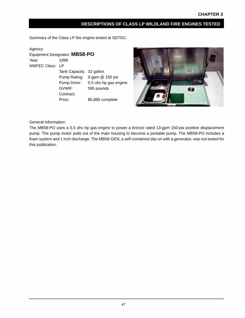
Summary of the Class LP fire engine tested at SDTDC.
Agency:Equipment Designator: MB58-POYear: 1998NWFEC Class: LP
Tank Capacity: 32 gallonPump Rating: 9 gpm @ 150 psiPump Drive: 5.5 ohv hp gas engineGVWR: 595 poundsContract:Price: $5,885 complete
General Information:The MB58-PO uses a 5.5 ohv hp gas engine to power a bronze rated 13-gpm 150-psi positive displacementpump. The pump motor pulls out of the main housing to become a portable pump. The MB58-PO includes afoam system and 1 inch discharge. The MB58-GEN, a self-contained slip-on with a generator, was not tested forthis publication.

48
CHAPTER 3
DESCRIPTIONS OF CLASS A WILDLAND FIRE ENGINES TESTED
Summary of the Class A wildland fire engine tested at SDTDC.
Agency: USDA FSEquipment Designator: Robwen Model 180 Slip-OnYear: 1998NWFEC Class: A
Tank Capacity: 96 gallonPump Rating: 52 gpm @ 200 psiPump Drive: Auxiliary engineGVWR: N/AContract: GSAPrice: $10,000 fire package only
General Information:The Robwen Model FS180 is a slip-on unit with a Robwen Model 1890 centrifugal pump and a Model 500positive pressure foam proportioner. Robwen designed its Model 180 to mate with the Briggs and Stratton 18-hpVanguard engine. The pump and foam proportioner are mounted on an aluminum diamond plate skid base. Theslip-on is plumbed with brass, stainless, and hard-anodized aluminum fittings. Added features include a Hannayhose reel, hour meter, and spark arrester.

49
CHAPTER 3
DESCRIPTIONS OF CLASS B WILDLAND FIRE ENGINES TESTED
Class B wildland fire engines tested at SDTDC.
Agency: USDA FS R-2Equipment Designator: Model 52Year: 1997NWFEC Class: B
Tank Capacity: 290 gallonPump Rating: 80 gpm @ 200 psiPump Drive: Auxiliary engineGVWR: 15,000 poundsContract: R-1Price: $47,214 complete
$14,214 fire package only
General Information:The Model 52 is designed to fit on an 8- or 9-foot flatbed truck with a 15,000-pound GVWR. It has a cab to axledistance of 60 inches and a 5- or 6-speed manual transmission. The Model 52 consists of a Wajax Model BB-4pump, storage compartments, exposed plumbing, an around-the-pump foam system, and a 290-gallon fiberglasswater tank.
Agency: USDA FS R-4Equipment Designator: Model 52 4X4Year:NWFEC Class: B
Tank Capacity: 620 gallonsPump Rating: 80 gpm @ 200 psiPump Drive: Auxiliary engineGVWR: 33,000 poundsContract: R-1Price: $17,976 fire
package only
General Information:The Model 52 is mounted on a 24,500 to 33,000 pound GVWR 4X2 or 4X4 truck with a cab to axle distance of84 inches and a 5- or 6-speed manual transmission. The Model 52 consists of a Wajax Model BB-4, four stagecentrifugal pump and hand primer, a hose reel, storage compartments, plumbing, and a 620-gallon (useablewater) fiberglass water tank.

50
CHAPTER 3
DESCRIPTIONS OF CLASS B WILDLAND FIRE ENGINES TESTED
Agency: USDA FS R-5Equipment Designator: Model 33UYear:NWFEC Class: B
Tank Capacity: 262 gallonsPump Rating: 70 gpm @ 200 psiPump Drive: Auxiliary engineGVWR: 15,000 poundsContract: R-6Price: $59,700 complete
$24,300 fire package only$12,800 utility box
General Information:The Model 33U is built on a Ford or General Motors 15,000 pound GVWR chassis. It has a wheelbase of 136inches, a cab to axle distance of 60 inches, a turbo diesel engine, and a 5- or 6-speed manual transmission. Thefire package includes a Wildfire Pacific BB-4 auxiliary pump, stainless steel welded plumbing, one-quarter-turndrop out style valves, Hale oilless primer, Robwen Model 500 foam proportioner, and a 262-gallon (useablewater) polypropylene water tank with a built-in 15-gallon foam concentrate reservoir.
Agency: USDA FS R-6Equipment Designator: Model 45Year:NWFEC Class: B
Tank Capacity: 312 gallonsPump Rating: 70 gpm @ 200 psiPump Drive: PTOGVWR: 15,000 poundsContract: R-6Price: $64,700 complete
$42,100 firepackage and utility box
General Information:The Model 45 is built on a Ford or General Motors 15,000 pound GVWR chassis. It has a wheelbase of 136inches, a cab to axle distance of 60 inches, a turbo diesel engine, and a 5- or 6-speed manual transmission. Thefire package includes a Gorman Rupp 02F1 PTO pump, stainless steel welded plumbing, one-quarter-turn dropout style valves, Hale oilless primer, Robwen Model 500 foam proportioner, and a 312-gallon (useable water)polypropylene water tank with a built-in 25-gallon foam concentrate reservoir.
51
CHAPTER 3
DESCRIPTIONS OF CLASS B WILDLAND FIRE ENGINES TESTED
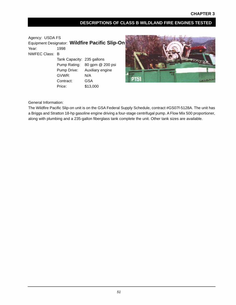
Agency: USDA FSEquipment Designator: Wildfire Pacific Slip-OnYear: 1998NWFEC Class: B
Tank Capacity: 235 gallonsPump Rating: 80 gpm @ 200 psiPump Drive: Auxiliary engineGVWR: N/AContract: GSAPrice: $13,000
General Information:The Wildfire Pacific Slip-on unit is on the GSA Federal Supply Schedule, contract #GS07f-5128A. The unit hasa Briggs and Stratton 18-hp gasoline engine driving a four-stage centrifugal pump. A Flow Mix 500 proportioner,along with plumbing and a 235-gallon fiberglass tank complete the unit. Other tank sizes are available.

52
CHAPTER 3
DESCRIPTIONS OF CLASS C WILDLAND FIRE ENGINES TESTED
Summary of the Class C wildland fire engine tested at SDTDC.
Agency: USDA FS R-5Equipment Designator: Model 42Year: 1990NWFEC Class: C
Tank Capacity: 261 gallonsPump Rating: 94 gpm @ 300 psiPump Drive: PTOGVWR: 22,500 poundsContract: R-5Price: $68,000 complete
General Information:The Model 42 is built on a Ford F-Series 24,000 pound GVWR chassis. It has a wheelbase of 129 inches, a cabto axle distance of 60 inches, a 170-hp Ford diesel engine, and a 5-speed manual transmission. The Model 42fire package includes a transmission PTO, a Waterous CPK1 pump, a KK foam proportioner, a hose reel andtank top hose tray or hose basket, emergency lighting, control panel, 261-gallon (useable water) galvanizedwater tank, and storage compartments.

53
CHAPTER 3
DESCRIPTIONS OF CLASS D WILDLAND FIRE ENGINES TESTED
Summary of Class D wildland fire engines tested at SDTDC.
Agency: USDA FS R-3Equipment Designator: Model 46Year: 1992NWFEC Class: D
Tank Capacity: 545 gallonsPump Rating: 200 gpm @ 300 psiPump Drive: PTOGVWR: 31,200 poundsContract: R-5Price: $84,000 complete
General Information:The Model 46 is built on a 30,000 to 33,000 pound GVWR chassis with an 84-inch cab to axle distance and hasa 5- or 6-speed manual transmission. The Model 46 fire package consists of a Hale CBP centrifugal pump drivenby a transmission PTO, Hale fluidless primer, flow mix proportioner, a hose reel, control panel, 545-gallon (useablewater) polypropylene water tank, and storage compartments for suction hose and accessories.
Agency: USDA FS R-3Equipment Designator: Model 71Year: 1994NWFEC Class: D
Tank Capacity: 621 gallonsPump Rating: 200 gpm @ 300 psiPump Drive: PTOGVWR: 33,000 poundsContract: R-5Price: $99,000
General Information:The Model 70/71 is built on a Navistar International 4900 chassis (conventional cab for Model 70, crew cab forthe Model 71). The engine is an International DT-466E, inline 6-cylinder diesel with 210 hp. The transmission isa 6-speed manual Fuller FS-8206A. The Model 70/71 fire package consists of a transmission PTO, Hale ModelCBP-4 pump, Hale oilless primer, Flow Mix proportioner, 2 Hannay live reels, emergency lighting, control panel,621-gallon (useable water) polypropylene tank, and storage compartments.

54
CHAPTER 3
DESCRIPTIONS OF CLASS D WILDLAND FIRE ENGINES TESTED
Agency: USDA FS R-5Equipment Designator: Model 62 4X2Year: 1997NWFEC Class: D
Tank Capacity: 545 gallonsPump Rating: 250 gpm @ 300 psiPump Drive: PTOGVWR: 33,000 poundsContract: GSAPrice: $140,000 complete
General Information:The Model 62 body build-up is on a Navistar International 4900 Crew Cab chassis with a 9-inch extension(approximately). The wheelbase is 170 inches with a cab to axle distance of 55 inches. The engine is anInternational DT-466E, electronic diesel with 250 hp at 2300 rpm. The transmission is a 6-speed manual FullerFS-8206A, with a 2-speed rear axle. The Model 62 4X2 fire package consists of a transmission PTO, a DarleyJMP-500 two-stage pump, FoamPro 2001 proportioner, 2 Hannay live reels, emergency lighting, control panel,and 545-gallon (useable water) polypropylene tank, and storage compartments for hose and accessories. Thistransmission is no longer available. The unit now uses an Allison 6-speed MD 3560.
Agency: USDA FS R-5Equipment Designator: Model 62 4X4Year: 1997NWFEC Class: D
Tank Capacity: 545 gallonsVolume Pump: 392 gpm @ 300 psiPressure Pump: 93 gpm @ 400 psiPump Drive: PTOGVWR: 33,000 poundsContract: GSAPrice: $140,000
General Information:The Model 62 body build-up is on a Navistar International 4900 Crew Cab chassis with a 9-inch extension(approximately). The wheelbase is 170 inches with a cab to axle distance of 55 inches. The engine is anInternational DT-466E, electronic diesel with 250 hp at 2300 rpm. The transmission is a 6-speed manual, FullerFS-8206A. The Model 62 4x4 fire package consists of a transmission PTO, a Darley HM-500 pump (driven offthe transfer case for stationary pumping), a Waterous CK1 (for pump and roll capability), a FoamPro 2001proportioner, 2 Hannay live reels, emergency lighting, control panel, and 545-gallon (useable water) polypropylenetank, and storage compartments for hose and accessories.

55
CHAPTER 3
DESCRIPTIONS OF CLASS D WILDLAND FIRE ENGINES TESTED
Agency: USDA FS R-5Equipment Designator: Model 62 PrototypeYear: 1999NWFEC Class: D
Tank Capacity: 480 gallonVolume Pump: 315 gpm @ 150 psiPressure Pump: 400 gpm @ 150 psiPump Drive: PTOGVWR: 33,000 poundsContract: GSAPrice: $170,000
General Information:The Model 62 body build-up is on a Navistar International 4900 Crew Cab chassis with a 9-inch extension(approximately). The wheelbase is 170 inches with a cab to axle distance of 55 inches. The engine is anInternational DT-530E, electronic diesel with 250 hp at 2300 rpm. The transmission is an Allison Model MD3560.The Model 62 Prototype fire package consists of a transmission PTO, a Darley JMP-500 pump, a FoamPro 2001proportioner, an optional CAFS System 120 CFM at 125 psi, 2 Hannay live reels, emergency lighting, controlpanel, a 480-gallon (useable water) polypropylene tank, and storage compartments for hose and accessories.
Agency: USDA FS R-6Equipment Designator: Model 75Year: 1994NWFEC Class: D
Tank Capacity: 530 gallonsPump Rating: 200 gpm @ 300 psiPump Drive: PTOGVWR: 31,000 poundsContract: R-6Price: $119,800 complete
$69,900 firepackage and utility box
General Information:The Model 75 is built on a Ford F-Series, International "S" Series, or Freightliner FL70 28,000 pound GVWRchassis. The wheelbase is 157 inches with a cab-to-axle distance of 84 inches. It has a 235- to 250-hp turbodiesel engine, an Allison 5-or 6-speed automatic transmission, and either an Allison transmission retarder or aTelma electric driveline retarder. The fire package includes a Darley HM250 PTO pump, stainless steel weldedplumbing, one quarter-turn drop out style valves, a Hale fluidless primer, a FoamPro 2001 proportioner, and a530-gallon (useable water) polypropylene tank with a 50-gallon foam concentrate reservoir.

56
CHAPTER 3
DESCRIPTIONS OF CLASS D WILDLAND FIRE ENGINES TESTED
Agency: USDA FS R-6Equipment Designator: Model 80Year: 1995NWFEC Class: D
Tank Capacity: 984 gallonsPump Rating: 200 gpm @ 300 psiPump Drive: PTOGVWR: 33,000 poundsContract: R-6Price: $123,500 complete
$73,600 fire package and utility box
General Information:The Model 80 is built on a Ford F-Series, International "S" Series, or Freightliner FL70 32,000 pound GVWRchassis. The wheelbase is 180 inches with a cab to axle distance of 108 inches. It has a 235- to 250-hp turbodiesel engine, an Allison 5-or 6-speed automatic transmission, and either an Allison transmission retarder or aTelma electric driveline retarder. The fire package includes a Darley HM250 PTO pump, stainless steel weldedplumbing, one-quarter-turn drop out style valves, a Hale fluidless primer, a FoamPro 2001 proportioner, and a984-gallon (useable water) polypropylene tank with a 50-gallon foam concentrate reservoir.

57
APPENDIX A
ADDITIONAL INFORMATION ON MAJOR COMPONENTS AND SYSTEMS
TANKS
The proper tank design can contribute greatly to thesafety and longevity of the fire vehicle. Since thevehicle’s center of gravity must be low, and because alarge tank full of water is very heavy, the placementand size of the tank is important. Low profile,rectangular shaped tanks are preferred since theyprovide better stability on side slopes and whilecornering. Place tanks so that the center of gravity ison, or just ahead of, the rear axle. With slip-on units, ifthe payload is too far forward, the result is oftenoverloading of the front axle.
Baffles are essential inside the tank to prevent massivewater shifts on slopes or curves. Without baffles, largechanges in water momentum can occur that couldcause a roll over of the vehicle, or tank failure. Bafflesshould be installed to allow waterflow at the bottomand airflow at the top.
Tanks are usually constructed of mild steel, stainlesssteel, fiberglass, or polyurethane. The choice ofmaterial is based on cost, ease of manufacture, tankweight, and corrosion resistance. Mild steel tanksshould be protected from corrosion. Stainless steeltanks are more corrosion resistant, but can beexpensive. Fiberglass and polyurethane tanks aregenerally more costly than steel tanks, but arecorrosion free.
Due to the cleaning action of foam, which leads tocorrosion, using steel tanks in a vehicle equipped witha foam system is not recommended. Tank fabricationis best left to experienced manufacturers since theyusually come with a good warranty.
PUMP CHARACTERISTICS
The pump is literally the heart of the wildland fireengine. If its performance is not adequate to serve theneeds of the user, the engine will be unsatisfactoryeven if all other components are suitable. Considerthe flow, pressure, and ability to create suction lift andalso reliability and maintainability when selecting thepump.
Pumps are either centrifugal or positive displacement.Both types are used in wildland fire fighting equipment,but the centrifugal pump is by far the most popular.The centrifugal pump creates an outward force froma center of rotation (known as the eye) to move orimpel water. With these pumps, the volume will varywith speed (rpm) and pressure. Centrifugal pumps areusually larger than positive displacement pumps andare employed for higher volumes.
Positive displacement pumps move a given quantityof water with each stroke or revolution of the piston orimpeller. Volume depends mainly on speed (rpm). Therotary gear, vane, cam-and-piston, and rotary pistonare typical units. Most are self-priming. Most requirerelief valves to handle line surges, overloads, and flowsnot needed at the nozzle. Typical gear pumps havetight tolerances between the rotating parts and thepump housing, which may be damaged by pumpingwater with impurities such as silt and sand.
PUMP RATINGS
Pumps are rated by the gallons per minute (gpm), atvarying psi. Below are NFPA’s pump ratings andpressures as are currently (July 2000) being suggestedin the draft of “NFPA 1906 Standard for WildlandApparatus,” now being revised. Pump performanceon wildland fire apparatus is rated by NFPA as a low-pressure pump, a medium-pressure pump, a high-pressure pump, or an extra-high-pressure pump.
If the pump is rated as a low-pressure pump, it shallflow at one of the following rated capacities at 100-psinet pump pressure: GPM 10, 20, 30, or 50.
If the pump is rated as a medium-pressure pump itshall be capable of delivering one of the ratedcapacities listed below under the following conditions:GPM 30, 60, 90, 120, 250, 350, 400, or 500.
(a) 100 percent of rated capacity at 150 psi netpump pressure.
(b) 70 percent of the rated capacity at 200 psi netpump pressure.
(c) 50 percent of the rated capacity at 250 psi netpump pressure.

58
APPENDIX A
ADDITIONAL INFORMATION ON MAJOR COMPONENTS AND SYSTEMS
If the pump is rated as a high-pressure pump, it shallflow at one of the following rated capacities at 300-psinet pump pressure: GPM 10, 20, 30, 50, 100, or 200.
If the pump is rated as an extra-high-pressure pump,it shall flow at one of the following rated capacities at400-psi net pump pressure: GPM 10, 20, 30, 50, 100,or 200.
PRIMING SYSTEM
A priming pump is generally necessary to initiallyevacuate the air and fill a centrifugal pump with theliquid to be pumped. Exhaust, hand, and electricprimers are available. There are positive displacementand self-priming centrifugal pumps that do not need aprimer. Operator convenience, available mountingspace, cost, maintenance requirements, and otherfactors influence the type of primer selected. Someprimers require a primer pump fluid such as oil orantifreeze. Some of these fluids are unacceptable foruse in wildland equipment. Pumps that do not requirethese fluids will not discharge the fluid on to the groundand are preferred.
When a centrifugal pump is full of water, it will createquite a high vacuum; but when the pump has beendrained, and contains only air, it will not producevacuum. To obtain a prime, a vacuum must be createdwithin the pump by some other means. A priming pumpis used which should develop a vacuum of at least 17inches of Hg. The priming pump evacuates air fromthe fire pump and when connected with a water sourceis replaced with water.
There are four methods that can be used to prime acentrifugal pump: two that prime consistently and twothat do not prime consistently. These methods areshown in table A1.
Table A1—Methods used to prime a centrifugal pump.
Methods that prime consistently
• Priming from the suctionwith the pump running.
• Priming from the dischargewith the pump not running.
Methods that DO NOT prime consistently
• Priming from the suctionwith the pump not running.
• Priming from the dischargewith the pump running.
The following suggestions should be adhered to forbest priming and pump performance when primingfrom the suction with the pump running:
• A check valve should be used at the discharge ofthe pump.
• The prime should be taken at the eye of theimpeller or at the top of the inlet to the pump.
• A smooth bell-shaped strainer inlet should be usedon the end of the suction hose; a foot valvedegrades performance.
• For rated pump performance, adequate suctionhose size diameter should be used; consult NFPA1906, Suction Hose Rating Criteria.
• Do not use any longer suction hose thannecessary.
• There should be no humps in the suction line. Ifthere are humps in the suction line, a prime orsuction should also be taken at the top of the humpas well as at the inlet to the pump.
The following suggestions should be adhered to forbest priming and pump performance when primingfrom the discharge with the pump not running:
• A check valve should be used at the discharge ofthe pump.

59
APPENDIX A
ADDITIONAL INFORMATION ON MAJOR COMPONENTS AND SYSTEMS
• The prime should be taken at the high point of thepump discharge and the engine started after pumpprime is achieved.
• A smooth bell-shaped strainer inlet should be usedon the end of the suction hose; a foot valvedegrades performance.
• For rated pump performance, adequate suctionhose size diameter should be used; consult NFPA1906, Suction Hose Rating Criteria.
• Do not use any longer suction hose thannecessary.
• Do not allow humps in the suction line.
PTO’S VERSUS AUXILIARY ENGINES
Advantages of a PTO Fire Pump
• Has fewer parts than auxiliary engine driven firepumps; hence, higher reliability.
• Requires no cabinetry space, allowing more spacefor water and equipment.
• Weighs less than an auxiliary engine driven firepump; hence more water or equipment can becarried.
• Hg has no significant loss of pump performancewith increase in altitude when a PTO is used todrive the fire pump (because the fire truck chassisengine generally has much more power thanrequired by wildland fire engine pumps).
• Is less costly above about 25–30 hp than theauxiliary fire pump.
• Has no problem with fueling, and no second fueltank is required if different fuel is used by theauxiliary engine than the chassis.
• Has a lower center of gravity resulting in increasedvehicle stability.
• Can be designed so it will make a satisfactoryrunning attack.
• Has a pump suction intake generally lower thanfound on an auxiliary engine driven pump; hencea higher lift capability when drafting.
Disadvantages of a PTO Fire Pump
• Requires more planning and engineering.
• May be more costly on small performancepumps—25–30 hp and lower.
• May be difficult to fit PTO on low GVWR chassis—12,000 lb GVWR and lower.
Advantages of an Auxiliary Engine DrivenPump
• Makes running attacks at any speed.
• Requires less planning and engineering tointegrate into a wildland fire engine than a PTOpowered pump.
• Installs and sets up much quicker than a PTOunit.
• Has lower cost for units under 25–30 hp.
Disadvantages of an Auxiliary EngineDriven Pump
• Requires more space than PTO driven pumps,and weighs more than a PTO driven pump.
• Has a loss of pump performance with an increasein altitude.
• Is more costly above about 25–30 hp than a PTOdriven unit.
• May require different fuel than chassis; hencerequiring two fuel tanks of different fuel types.
• Has a higher center of gravity decreasing vehiclestability if the auxiliary engine and pump are largeand heavy.
• Pump suction intake is generally higher than aPTO driven pump; the engine will have less liftcapability when drafting.

60
APPENDIX A
ADDITIONAL INFORMATION ON MAJOR COMPONENTS AND SYSTEMS
FOAM SYSTEM OR FOAM PROPORTIONINGEQUIPMENT
During the last decade, the improved fire extinguishingproperties of “Class A” foam have become increasinglyrecognized. This has resulted in a marked increase inthe use of foam to protect natural resources andimprovements. When using foam, it is desirable toinject the foam concentrate at a set proportion,regardless of water flow or pressure, directly into thedischarge, or high-pressure side of the water pump.There are a number of proportioning systems used toproportion foam concentrate into water streams foruse with standard nozzles, aspirating nozzles, orcompressed air foam systems (CAFS).
Two basic types of foam concentrate proportioningsystems are shown in table A2.
Table A2—Two basic types of foam concentrateproportioning systems.
Manually regulatedproportioning systems include
• batch mixing
• suction-side proportioner
• in-line eductor
• variable flow bypass eductor
• direct injection, manually regulated
Automatic regulatingproportioning systems include
• balanced pressure venturi system
a. pump system
b. bladder tank systems
• water and/or motor meter proportioner
• around-the-pump proportioner
• direct injection, automatic regulating
The advantage of manually regulated proportioningsystems is low initial cost. However, manuallyregulated proportioning systems (other than batchmixing) have the potential of using more foam
concentrate than necessary. This may negate theirinitial cost savings and become the most costlyproportioning system.
Automatic regulating proportioning systems have beendesigned to remain proportional over a wide range offlows. These systems are not affected by changes inengine pressure, changes in hose length or size, orchanges in nozzle adjustments, size, or elevation.Usually they inject the foam concentrate into thedischarge side of the pump. Proportioning systemson engines should be tested prior to accepting theunit to ensure they are operating properly.
WEIGHT AND BALANCE
Fire engines are often unique pieces of equipment thatare usually built by adding firefighting apparatus tocommercial truck chassis. The design limits of the truckchassis are the most important information that thetruck manufacturer provides its customer. The fireengine designer and builder must be careful to avoidexceeding the maximum design weight and axle ratingof the chassis.
If you plan to use the vehicle off-road for a goodpercentage of the time, the manufacturers design limitsshould be reduced since they are based on use onpaved highways. Exceeding the chassismanufacturers design limits will cause a vehicle to beout of compliance with federal safety standards, andeven worse, to be unsafe. Steering, braking, andstability will be compromised if manufacturers designlimits are not heeded. Good examples, along withmethodology and tables on how to calculate weightand balance can be found in truck-chassismanufacturer’s data books.
Gross Vehicle Weight Rating (GVWR) andGross Axle Weight Rating (GAWR)
It is a requirement of the National Highway SafetyAdministration, U.S. Department of Transportationregulations (49 CFR, Part 567—Certification) that theGVWR and GAWR of a vehicle must be posted in thevehicle on a permanently affixed label.

61
APPENDIX A
ADDITIONAL INFORMATION ON MAJOR COMPONENTS AND SYSTEMS
GVWR is the chassis manufacturer’s specifiedmaximum load carrying capacity of a vehicle. Thesum of the front GAWR and the rear GAWR for thevehicle can be equal to or greater than the GVWR.However, the in-service weight or “gross vehicleweight” must not exceed 90 percent of the GAWR andGVWR as defined in the requirements of this guide.
It should be noted that the gross vehicle weightincludes the complete vehicle with all associatedattachments, accessories, payload, crew, andequipment. Experience has shown that over the lifeof a fire engine, more and more equipment is oftenadded. When specifying a vehicle, it is best to allowfor this increase in weight.
GAWR is the chassis manufacturer’s specifiedmaximum load carrying capacity of an axle system,as measured at the tire/ground interface. The axlesystem includes, but is not limited to, the axle, tires,suspension, wheels, frame, brakes, and appliedengine torque. The gross axle weights must alwaysbe equal to or less than the GVWR. The GVWR cannotbe more than the sum of the GVAW, although it maybe less, because the frame and other components maynot be strong enough to carry the load that the twoaxles can carry.
Matching Slip-on Units to Chassis
It is essential that slip-on units be matched properlywith the truck chassis. To do this, the followinginformation is required: the GVWR, GAWR, curbweight, and axle weights of the truck and the weightand center of gravity of the slip-on unit. Adding thetruck and slip-on weights and taking into considerationthe crew and equipment, it is easy to determine if theunit will comply with the GVWR. To determinecompliance with the GAWR, the center of gravity ofthe slip-on must be used to calculate the axle loadings.Some slip-on units may have their center of gravitytoo close to the front of the vehicle, which can causeoverloading on the front axle.
Vehicle Stability
Due to the nature of fire engines and the way they areused (FS engines are used in emergency situations,
often on rough roads, and in harsh conditions), vehiclestability is extremely important. The height of the centerof gravity of the fully equipped and loaded vehicleshould be no greater than 75 percent of the rear trackwidth of the vehicle (or chassis manufacturer’sguidelines). Rear track width is measured from thecenter of the rear wheel assembly on one side to thecenter of the wheel assembly on the other side.
An alternate criteria is to place the fully loaded vehicleon a tilt table. The tilt table should have an aggressivesurface and the down slope tires should not beblocked. The vehicle is considered to have adequatestability if the table can be raised to 30 degrees beforelifting the front or rear tire.
Vehicle Certification
The final stage manufacturer must affix a permanentcertification label or tag that certifies that the unit meetsall required federal standards pertaining to themanufacture and completion of the fire apparatus. Thisis required by CFR 49, Part 567—Certification.
ADDITIONAL RESOURCES FOR DESIGNAND USE INFORMATION
Within the wildland firefighting community, there are anumber of groups that are interested in the designand use of fire engines. These groups can be atremendous resource for those designing and selectingfire engines and associated apparatus.
The FEWT of the NWCG coordinates the fireequipment and fire retardant chemical needs,development, and implementation between Federaland State agencies. FEWT publishes the “WaterHandling Equipment Guide.” This publication providesphotographs and data on a variety of fire engines fromFederal and State agencies in the United States. Website: http://www.nwcg.gov
The Roscommon Equipment Center (REC) is acooperative program between the National Associationof State Foresters and the Michigan Department ofNatural Resources. REC develops and testsequipment for wildland fire control. It is located at the

62
APPENDIX A
ADDITIONAL INFORMATION ON MAJOR COMPONENTS AND SYSTEMS
Forest Fire Experiment Station, Roscommon, MI. RECspecializes in the conversion of U.S. military vehiclesto wildland fire suppression units. It also focuses onthe equipment development needs of State and localwildfire forces. Web site: http://www.dnr.state.mi.us (Select Divisions, Forest Management, and thenRoscommon Equipment Center).
The NFPA is a nonprofit, voluntary membershiporganization. NFPA’s technical actions are focused onfacilitating the development and distribution of firesafety codes and standards. Web site: http://www.nfpa.org
NFPA publishes “NFPA 1906, Standard: for WildlandFire Apparatus,” a purchasing standard that specifiesthe minimum performance characteristics for wildlandapparatus (appendix B, figure 5). NFPA revises theirstandards about every 5 years, and is currently revising“Standard 1906: Wildland Fire Apparatus” publishedin 1995. The revision is scheduled for completion in2001.
The SDTDC is staffed with personnel with specializedskills and experience to provide consultation to FS fieldunits. Web site: http://fsweb.sdtdc.wo.fs.fed.us

63
APPENDIX B
VENDORS ON GSA CONTRACT
Since vendor names, addresses, phone numbers, andweb sites are constantly changing, we are providingthe web site for the list of vendors currently on theGSA contract. By having this direct access you canbe assured of having the most current informationavailable.
http://www.gsa.gov then Schedule E Library

64
GLOSSARY
Automatic Regulating Foam ProportioningSystem. A proportioning system that automaticallyadjusts the flow of foam concentrate into the waterstream to maintain the desired proportioning ratio.These automatic adjustments are made based onchanges in water flow or conductivity.
Apparatus. A motor-driven vehicle, or group ofvehicles, designed and constructed for the purposeof fighting fires. May be of different types, such asengines, water tenders, etc.
Aspirate (foam). To draw in gases (or othersubstances)—nozzle-aspirating systems draw air intothe nozzle to mix with the foam solution.
Bypass Eductor. An eductor with a bypass aroundthe venturi. This bypass generally has a variable orificeby which the flow rate around the eductor can becontrolled.
Balanced Pressure Venturi Foam ProportioningSystems. An automatic regulating proportioningsystem that employs a venturi, and the water pressureand foam concentrate pressure are equal.
CAFS. A compressed air foam system (CAFS) with:(1) an automatic regulating proportioning systeminjecting foam concentrate into the discharge orpressure side of the pump, (2) an air compressorinjecting air into the discharge or pressure side of thepump, and (3) proper controls and equipment tocontrol the CAFS.
Certification. The final stage manufacturer must affixa permanent certification label, or tag, which certifiesthat the unit meets all required federal standardspertaining to the manufacture and completion of thefire apparatus. This is required by CFR 49, Part 567—Certification.
Eductor. A device used to introduce and mix firechemical into a water stream. An eductor is a fittingwith three ports: an inlet for water flow, and outlet forwater flow, and an inlet for fire chemical concentrate.The flow of water through the eductor produces aregion of lower pressure at the fire chemical inlet,drawing the chemical into the water stream.
Foam Concentrate Proportioner Systems. A deviceor technique used to mix foam concentrate with waterto make foam solution.
General Services Administration. An agency of theU.S. Government that includes the Federal SupplyService, the Automated Data and TelecommunicationsService, the Public Buildings Service, and the NationalArchives and Records Service.
Gross Axle Weight Rating (GAWR). The valuespecified by the manufacturer as the maximumallowable weight placed on an axle of a vehicle whenfully equipped, including payload, fluids, andoccupants.
Gross Vehicle Weight (GVW). The total weight ofthe fully equipped, fully loaded vehicle. It includes theweight of the truck and its payload, the weight of theengine fluids, fuel, the driver and passengers—in short,anything and everything part of, contained in, orsupported by the vehicle, or simply the inservice weightof the vehicle.
Gross Vehicle Weight Rating (GVWR). The totalweight value specified by the manufacturer as themaximum weight of a single motor vehicle.
Incident Command System Classes. Standardizedon-scene emergency management classes specificallydesigned to have wildfire apparatus met the demandsof complex single or multiple incidents, withconsistency throughout agencies.
National Fire Protection Association (NFPA).Nonprofit educational and technical association formedin 1896, headquartered in Quincy, MA, and devotedto the protection of life and property from fire throughdevelopment of standards of fire protection and publiceducation.
National Wildfire Coordinating Group (NWCG). Agroup formed under the direction of the Secretaries ofthe Interior and Agriculture to improve the coordinationand effectiveness of wildland fire activities and providea forum to discuss, recommend appropriate action, orresolve issues and problems of substantive nature.
65
GLOSSARY
Payload. Weight of passengers and/or cargo beingcarried by a conveyance.
Priming. Filling pump with water when pump is takingwater not under a pressure head. Necessary forcentrifugal pumps.
Proportioner. A device that adds a predeterminedamount of foam concentrate to water to form foamsolution.
Shunt. A parallel or alternative path through which aportion or all of the flow may pass.
Slip-on Units. A self-contained unit including anauxiliary engine driven pump, piping, a tank, and hosestorage that is designed to be placed on a truckchassis, utility bed, flat bed, or trailer. These unitstypically can be placed on and removed from thevehicle with a minimum of time and effort.
Suction Lift. The number of feet (meters) of verticallift from the surface of the water to the center of thepump impeller.
Water Hammer. A force created by the rapiddeceleration of water, commonly created by closinga valve too quickly. Pressures developed in a waterhammer, proportional to the mass multiplied by thesquare of the velocity, can damage a pipe or hose.

66
BIBLIOGRAPHY
Federal Motor Vehicle Safety Standards. Code of Federal Regulations (CFR) 49, Part 571, Federal Motor VehicleSafety Standards.
Guidelines for designing wildland fire engines, reformatted for web page August 1998. Northeast Forest FireSupervisors, in cooperation with Michigan’s Forest Fire Experiment Station. Available: http://www.dnr.state.mi.us/www/fmd/ffes/NN3.html News note No. 3.
A discussion of important references and design concerns to help agencies fabricate efficient enginesfor their fire control needs.
McKenzie, Dan W. 1992. Compressed air foam systems for use in wildland fire applications. San Dimas, CA:U.S. Department of Agriculture, Forest Service, San Dimas Technology and Development Center.13 p.
Report covers equipment arrangements for compressed air foam systems for use in fighting wildlandfires.
McKenzie, Dan W. 1992. Proportioners for use in wildland fire applications. San Dimas, CA: U.S. Department ofAgriculture, Forest Service, San Dimas Technology and Development Center. 21 p.
Methods of proportioning foam concentrate into water to make foam solution that can be used withstandard nozzles, aspirating nozzles, or in a compressed air foam system (CAFS) for use in fightingwildland fires.
McKenzie, Dan W. 1996. Compressed air foam systems (CAFS) for region five water tenders. San Dimas, CA:U.S. Department of Agriculture, Forest Service, San Dimas Technology and Development Center. 17 p.
A response on what type of foam units and equipment should be used on fire prevention patrol engines,and what type of compressed air foam systems should be used on large water tenders (1500 to 3000gal).
National Wildland Coordinating Group. 1994. Water handling equipment guide. NFES 1275. Boise, ID: U.S.Department of Agriculture, U.S. Department of the Interior, National Association of State Foresters, NationalInteragency Fire Center. 171 p.
Provide field users in wildland fire fighting agencies with a basic information document on water handlingequipment.
National Wildland Coordinating Group. 1994. Wildland fire engine component guide. NFES 1871. Boise, ID:U.S. Department of Agriculture, U.S. Department of the Interior, National Association of State Foresters, NationalInteragency Fire Center. 112 p.
Specifications to assist wildland fire agencies in the selection of quality components for assembly intofire engines. Provides information on characteristics that should be considered to meet a wide range ofwildland fire engine user requirements.
NFPA 1901 Standard for Automotive Fire Apparatus. 1999. National Fire Protection Association. FANS/NFP1906. Quincy, MA. 148p.
The 1999 edition is a general update of the 1996 edition, which combines four fire apparatus standardsdesignated as NFPA 1901, Standard for Pumper Fire Apparatus; NFPA 1902, Standard for Initial AttackFire Apparatus; NFPA 1903, Standard for Mobile Water Supply Fire Apparatus; and NFPA 1904, Standardfor Aerial Ladder and Elevating Platform Fire Apparatus.

67
BIBLIOGRAPHY
NFPA 1906 Standard for Wildland Fire Apparatus. 1995. National Fire Protection Association, ANS/NFP 1906.Quincy. MA. 58 p.
A standard for apparatus that is basically designed and deployed to combat fire in the wildland.
![Safe Babies Court Teams 2016 County Evaluations Prepared ...term:name]/[node... · • Living Hope Center in Springerville offers parenting classes, operates the only DES-Certified](https://img.pdfslide.net/doc/110x75/5e80846be34bf61135505c2f/safe-babies-court-teams-2016-county-evaluations-prepared-termnamenode.jpg)