Embed Size (px)
Citation preview
ECNCLINFORMATION CENTER
"5 0644 000010490
United States ArmyTank-Automotive Command
Warren, Michigan 48090
TECHNICAL LIBRARYcLI REFERENCE COPY
CA Y3I lvivo
, M
INNOVATIVE MOBILITY DESIGNS UTILIZED ONFOREIGN WHEELED & TRACKED VEHICLES
July 1981
Copy-of -- Copies
DISTRIBUTION.
HQ DARCOM (4) Commandant (4)ATTN: DRCMR, DRCCE, DRCDE, US Army Field Artillery Center
DRCRA ATTN: ATSF, ATSF, ATSF-CD, ATSF-CD-M,Alexandria, VA 22333 ATSF-TSM-CN
Ft. Sill, OK 735.03Defense Information Center (1)Washington, D.C. Commandant ,i5)
US Army Transportation CenterATTN: ATSP, ATSP-CD, ATSP-CD-M (3)
Commander (1) Ft. Eustis, VA 23604US Army Tank-Automotive CommandATTN: DRSTA-CG TRADOC Liaison OfficeWarren, MI 48090 C/O ODCSOPS, HQ USAREUR (2 copies)
Commander (6) APO New York 09403
US Army Tank Automotive Command Coandant (2)ATTN: DRSTA-NG, DRSTA-NS DRSTA-R,
DRSTA-T DRSTA-Z, DRSTA-TSL US Army Engineering SchoolWarren, MI 48M90 ATTN: ATZA, ATZA-CD
Ft. Belvoir, VA 22060Commander (10)
TRADOC Commander (1)ATTN: ATCD, ATCD-S, ATCD-SL, ATCD-M, US Army Armt R&D Command
ATCD-O, ATCD-A, ATCD-P, ATCD-F, ATTN: TRADOC LOATCD-D-ATCD-MA Dover, NJ 07801
Ft. Monroe, VA
Commander (4) CommanderUS Army Logistics Center DARCOMATTN: ATCL, ATCL-FW,, ATCL-M, ATCL-MM ATTN: -DRCGS-L TRADOC LO (2 copies)Ft. Lee, VA 23801 5001 Eisenhower Avenue
Alexandria, VA 22333Commandant (3)US Army Armor Center CINCUSFK/EUSA (2)ATTN: ATZK, ATZK-CD, ATZK-CD-M ATTN: DJFt. Knox, KY 40121 ATTN: J3 TRNG & EX Br TRADOC LO
APO S.F. 96301
Commandant (4)US Army Infantry Center Commander (1)ATTN: ATSH, ATSH-CD, ATSH-CD-M, US MC Dev & Ed Qnd
ATST-TSM-HV HOCHMUTH Hall TRADOC Liaison Officer
Ft. Benning, GA 31905 Quantico, VA 22134
Commander (3) Commander (1)
CAC US Army Field Arty Bd
ATTN: ATZL-CAM-I, ATZL-SWR-M, ATZL-CS ATTN: ATSF-Bd
Ft. Leavenworth, KS 66027 Ft. Sill, OK 73503
Commandant (3) CommanderUS Army Ord Cen & Sch TACOMATTN: ATSL, ATSL-CD, ATSL-CD-M ATTN: ATFE-TA (2 copies)Aberdeen Proving Ground, MD 21005 Warren, MI 48090
DZSTIIBUTION
Commander (1)US Armed Forces ComuandATTN: AFLG-REGFt. McPherson, GA 30330
DirectorHigh Tech Test Bed9th Infantry Division (2 copies)Ft. Lewis, WA 98433
TRADOC LO to ESGC/O Defense Attache (3 copies)APO New York 09777
Commandant of the Marine CorpsCode LME-3, ATTN: LTC Southimayd (2 copies)Headquarters US Marine CorpsWashington, D.C. 20380
DirectorDevelopment Center, ATTN: LTC Woodhead (2 copies)Motor Transport Branch (D07)MCDECQuantico, VA 22134
FMF PAC Headquarters (1)G4 Camp HM Smith, ATTN: MAJ BoxHawaii 96861
Commanding Officer (1)Motor Transport School CompanyMarine Corps Service Support SchoolATTN: LTC KingMarine Corps BaseCamp Lejeune, NC 28542
Commander (5)USMC-LNO ATTN: MAJ PlunkettUS Army Tank Automotive CommandWarren, MI 48090
CommanderARADCO14ATTN: DRCPM-CAWS (2 copies)Dover, NJ 07801
TOTAL COPIES 80
DISCLAIMER
The findings in this report are not to be construedas an official Department of the Army position unlessso designated by other authorized documents.
TRADE NAMES
Use of trade names or manufacturers in this report doesnot constitute an official indorsement or approval ofthe use of such commercial hardware or software.
i
FORWARD
The intent of this paper is to briefly address some of the
effective methods utilized by foreign countries to enhance the
mobility of wheeled and tracked vehicles.
Many of the systems which are discussed in this paper have
been tested under the management of the US Army Tank-Automotive
Command. The merits of each of these systems in regards to
mobility performance has been evaluated.
ii
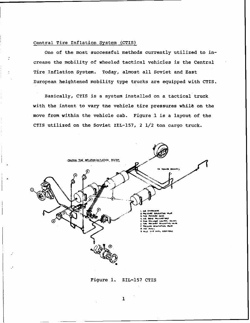
Central Tire Inflation System (CTIS)
One of the most successful methods currently utilized to in-
crease the mobility of wheeled tactical vehicles is the Central
Tire Inflation System. Today, almost all Soviet and East
European heightened mobility type trucks are equipped with CTIS.
Basically, CTIS is a system installed on a tactical truck
with the intent to vary the vehicle tire pressures whil on the
move from within the vehicle cab. Figure 1 is a layout of the
CTIS utilized on the Soviet ZIL-157, 2 1/2 ton cargo truck.
-CNT.AL T712E INFLATI-j2LFLATION_ YS.TEM
Figure i. ZIL-157 CTIS
1
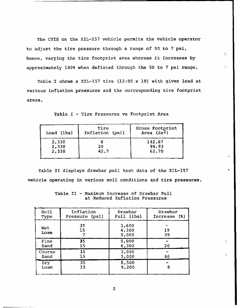
The CTIS on the ZIL-157 vehicle permits the vehicle operator
to adjust the tire pressure through a range of 50 to 7 psi,
hence, varying the tire footprint area whereas it increases by
approximately 180% when deflated through the 50 to 7 psi range.
Table I shows a ZIL-157 tire (12:00 x 18) with given load at
various inflation pressures and the corresponding tire footprint
areas.
Table I - Tire Pressures vs Footprint Area
Tire Gross FooterintLoad (ibs) Inflation (psi) Area (in)
2,330 8 142.672,330 20 94.932,330 42.7 62.70
Table II displays drawbar pull test data of the ZIL-157
vehicle operating in various soil conditions and tire pressures.
Table II - Maximum Increase of Drawbar Pullat Reduced Inflation Pressures
Soil Inflation Drawbar DrawbarType Pressure (psi) Pull (ibs) Increase (%)
35 3,600 -Wet 15 4,300 19
7 5,000 39
Fine 35 5,000 -Sand 15 6,300 26
Course 35 3,000Sand 15 5,000 66Dry 35 8,500 -Loam 15 9,200 8
2
Since CTIS does allow for increasing the vehicle tire foot-
print area, the vehicle has less ground pressure at the lower
tire operating pressures. Lower ground pressures will in turn
enhance the cross-country and soft soil mobility of a vehicle.
In Hub Planetary Final Drive
In hub, planetary final drive gear reduction is utilized by
numerous foreign wheeled vehicle manufacturers. By incorporat-
ing this feature, the vehicle differentials can be designed more
compactly and the axles and axle housings can also be made
smaller, therefore permitting greater vehicle ground clearance.
Hence, the higher the vehicle ground clearance, the greater the
terrain traversiiig capability a vehicle will have.
This method of planetary gear reduction is utilized by the
Soviets on the MAZ-537 Heavy Equipment Transporter, by the
Czechoslovakians on the TATRA-813 Cargo Truck, and by numerous
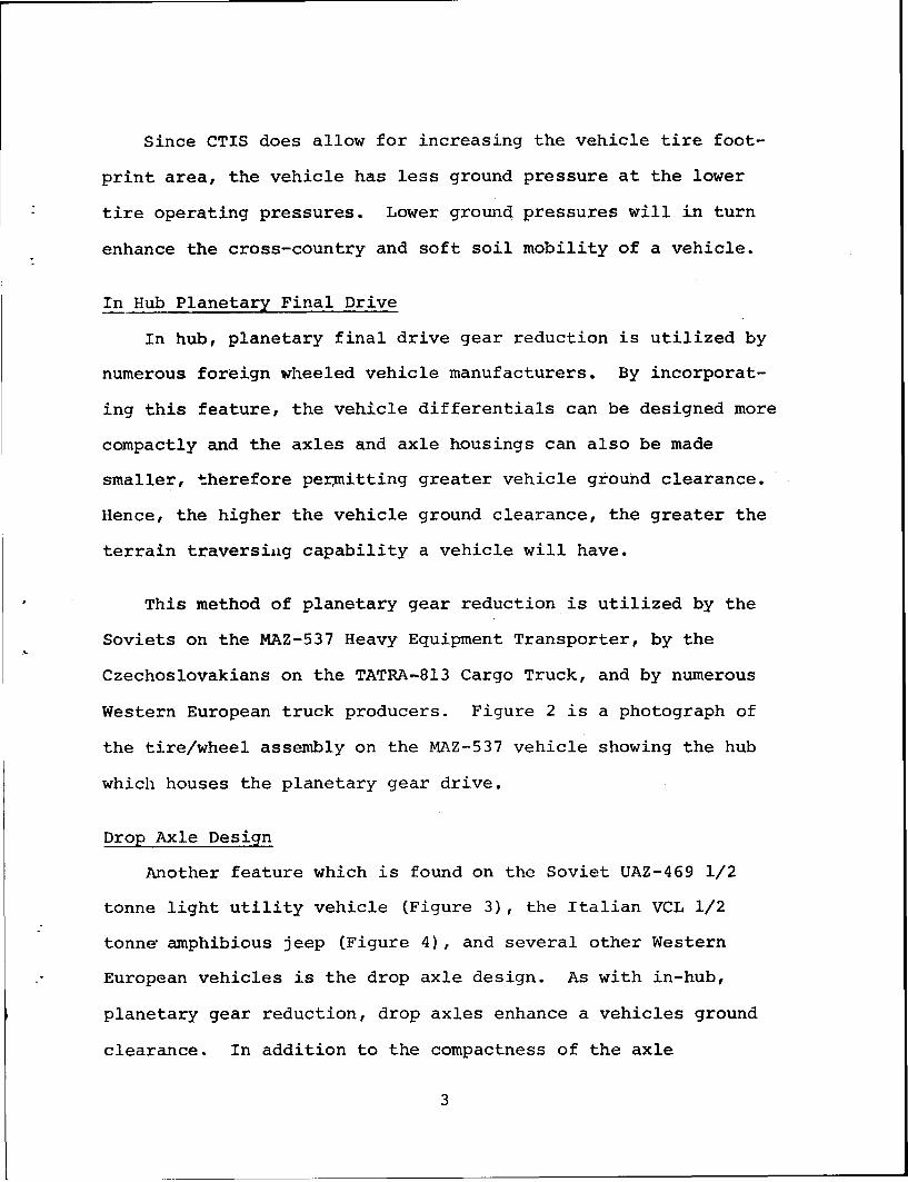
Western European truck producers. Figure 2 is a photograph of
the tire/wheel assembly on the MAZ-537 vehicle showing the hub
which houses the planetary gear drive.
Drop Axle Design
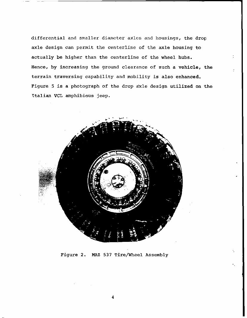
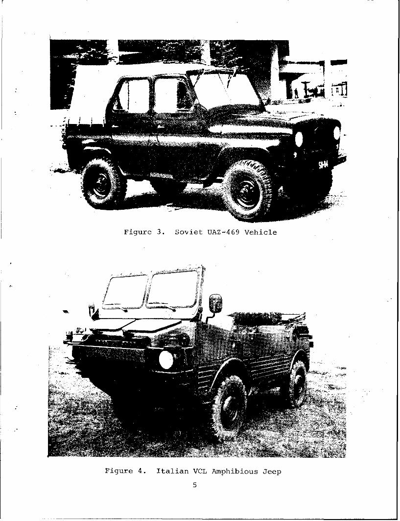
Another feature which is found on the Soviet UAZ-469 1/2
tonne light utility vehicle (Figure 3), the Italian VCL 1/2
tonne7 amphibious jeep (Figure 4), and several other Western
European vehicles is the drop axle design. As with in-hub,
planetary gear reduction, drop axles enhance a vehicles ground
clearance. In addition to the compactness of the axle
3
differential and smaller diameter axles and housings, the drop
axle design can permit the centerline of the axle housing to
actually be higher than the centerline of the wheel hubs.
Hence, by increasing the ground clearance of such a vehicle, the
terrain traversing capability and mobility is also enhanced.
Figure 5 is a photograph of the drop axle design utilized on the
Utalian VCL amphibious jeep.
Figure 2. MAZ 537 Tire/Wheel Assembly
4
A rU
Figure 3. Soviet UAZ-469 Vehicle
Figure 4. Italian VCL Amphibious Jeep
5
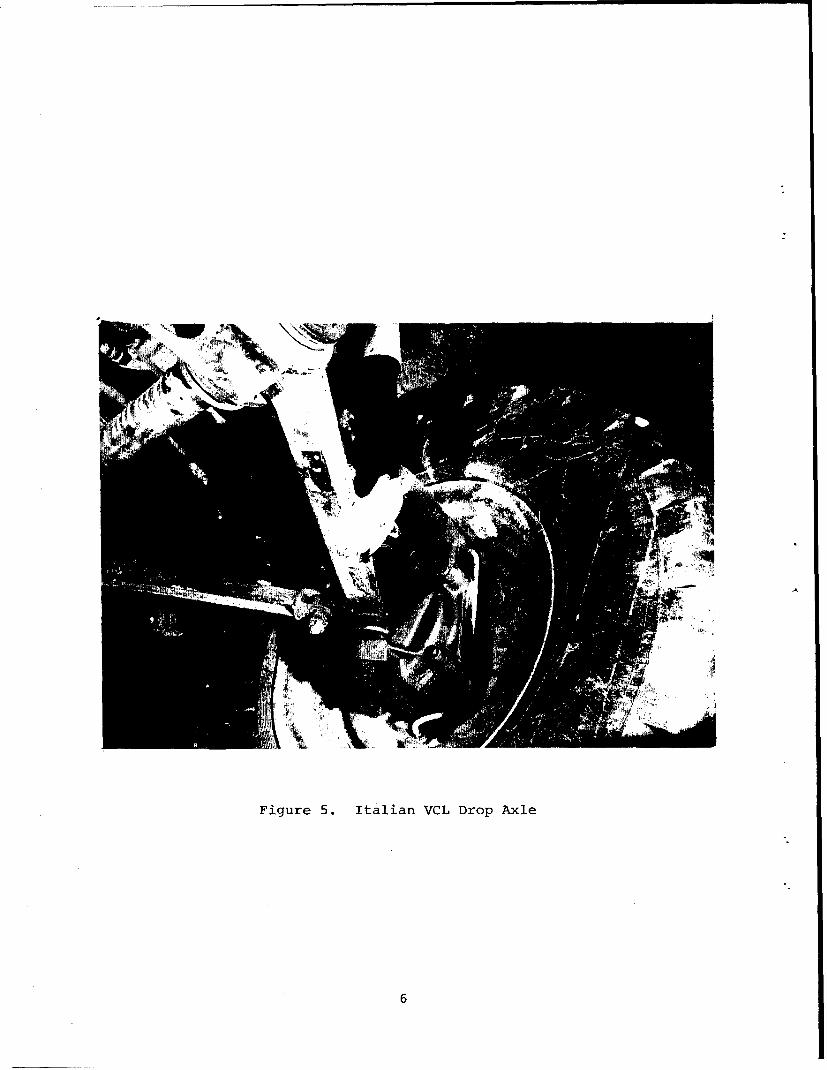
Figure 5. Italian VCL Drop Axle
6
S•i¸ i
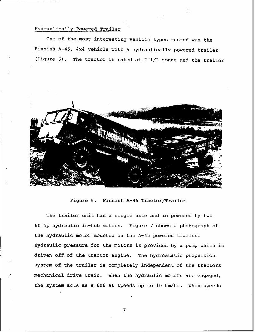
Hydraulically Powered Trailer
One of the most interesting vehicle types tested was the
Finnish A-45, 4x4 vehicle with a hydraulically powered trailer
(Figure 6). The tractor is rated at 2 1/2 tonne an• the trailer
[
Figure 6. Finnish A-45 Tractor/Trailer
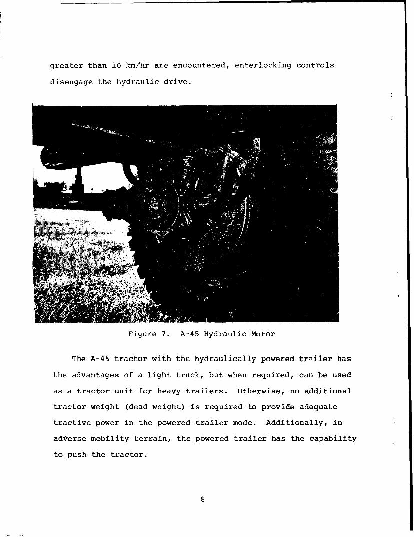
The trailer unit has a single axle and is powered by two
60 hp hydraulic in-hub motors. Figure 7 shows a photograph of
the hydraulic motor mounted on the A-45 powered trailer.
Hydraulic pressure for the motors is provided by a pump which is
driven off of the tractor engine. The hydrostatic propulsion
system of the trailer is completely independent of the tractors
mechanical drive train. When the hydraulic motors are engaged,
the system acts as a 6x6 at speeds up to i0 km/hr. When speeds
7
greater than 10 km/hr are encountered, enterlocking controls
disengage the hydraulic drive.
1,4-
Figure 7. A-45 Hydraulic Motor
The A-45 tractor with the hydraulically powered trailer has
the advantages of a light truck, but when required, can be used
as a tractor unit for heavy trailers. Otherwise, no additional
tractor weight (dead weight) is required to provide adequate
tractive power in the powered trailer mode. Additionally, in
adverse mobility terrain, the powered trailer has the capability
to push the tractor.
On extensive tests which were perfQrmed on this system, it
was determined that due to the hydraulic powered trailer, the
flexible frame of the A-45 configuration and the locking differ-
entials, the vehicle performed exceptionally well in difficult
hilly terrain, but less than adequate in soft soil conditions.
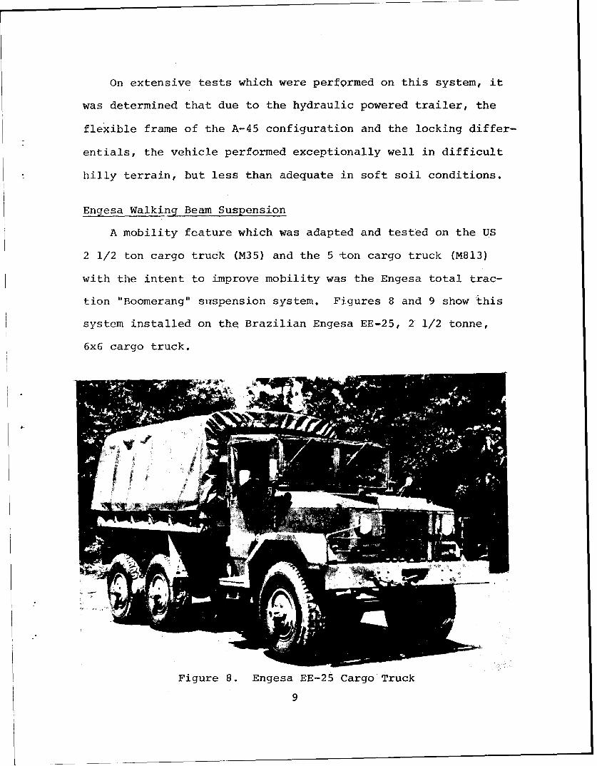
Engesa Walking Beam Suspension
A mobility feature which was adapted and tested on the US
2 1/2 ton cargo truck (M35) and the 5 ton cargo truck (M813)
with the intent to improve mobility was the Engesa total trac-
tion "Boomerang" suspension system. Figures 8 and 9 show this
system installed on the Brazilian Engesa EE-25, 2 1/2 tonne,
6x6 cargo truck.
/4N,
Figure 8. Engesa EE-25 Cargo Truck
9
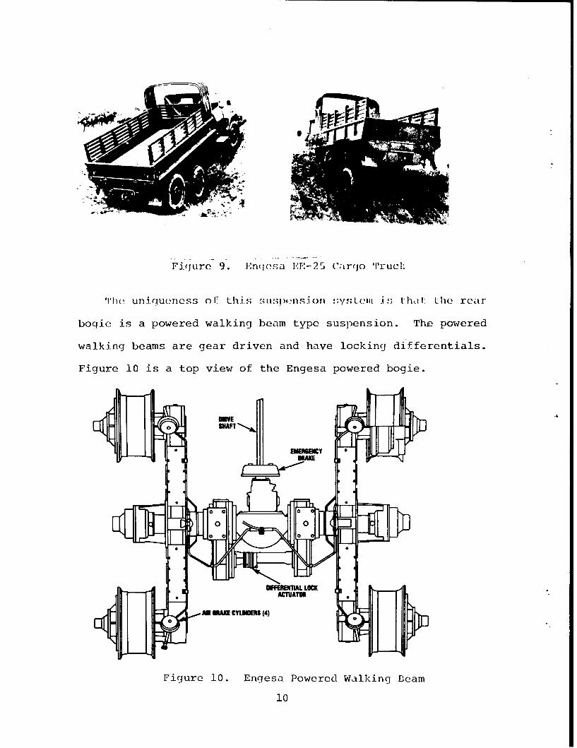
Fiqure 9. Enqesa 1r,F-:25 C arqo Tr iuei.
'Ihei uniqueness ofI this. stisp(-iisjon ;y Liiiis Llili: Lhie rear
bogie is a powered walking beam type suspension. The powered
walking beams are gear driven and have locking differentials.
Figure 10 is a top view of the Engesa powered bogie.
MEa SHAFT
0 10
One of the primary advantages of this type of suspension
system is that it has approximately 43" of wheel travel. The
main factor which limits wheel travel on this type of system
is the clearance allowed by the vehicle box or bed configura-
tion.
The Brazilian EE-25, 2 1/2 tonne, 6x6 cargo truck claims a
vehicle cone index (VCI) of approximately 26, which is con-
sidered good for cross-country mobility. Overall comparative
testing of the M35 and M813 vehicles with and without the
"boomerang" system indicated that. the Engesa system performed
better in vertical step climbing capabilities and in several
.isolated soft soil mobility courses than those vehicles with
the conventional suspension systems.
Manual Locking Differentials
If the wheel slip of a vehicle can be controlled in critical
situations, the mobility of a vehicle can be enhanced consider-
ably. Various tactical trucks have been developed with conven-
tional limited slip type differentials only to experience that
unless the differentials are positively locked, wheel slip
occurs at the expense of mobility.
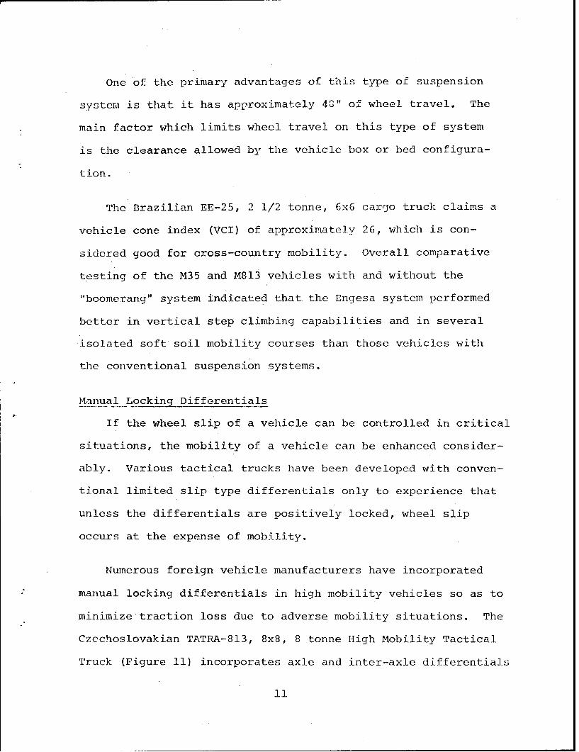
Numerous foreign vehicle manufacturers have incorporated
manual locking differentials in high mobility vehicles so as to
minimize traction loss due to adverse mobility situations. The
Czechoslovakian TATRA-813, 8x8, 8 tonne High Mobility Tactical
Truck (Figure 11) incorporates axle and inter-axle differentials
11
that can be positively locked. The primary purpose of the
inter-axle differential being to equalize the torque between the
axle differentials of which it is mounted. In addition, the
inter-axle differentials help eliminate tire scrub and drive
train "windup" which occurs when the wheels of two different
axles are forced to turn at the same speed.
Figure 11. Czechoslovakian TATRA-813 Vehicle
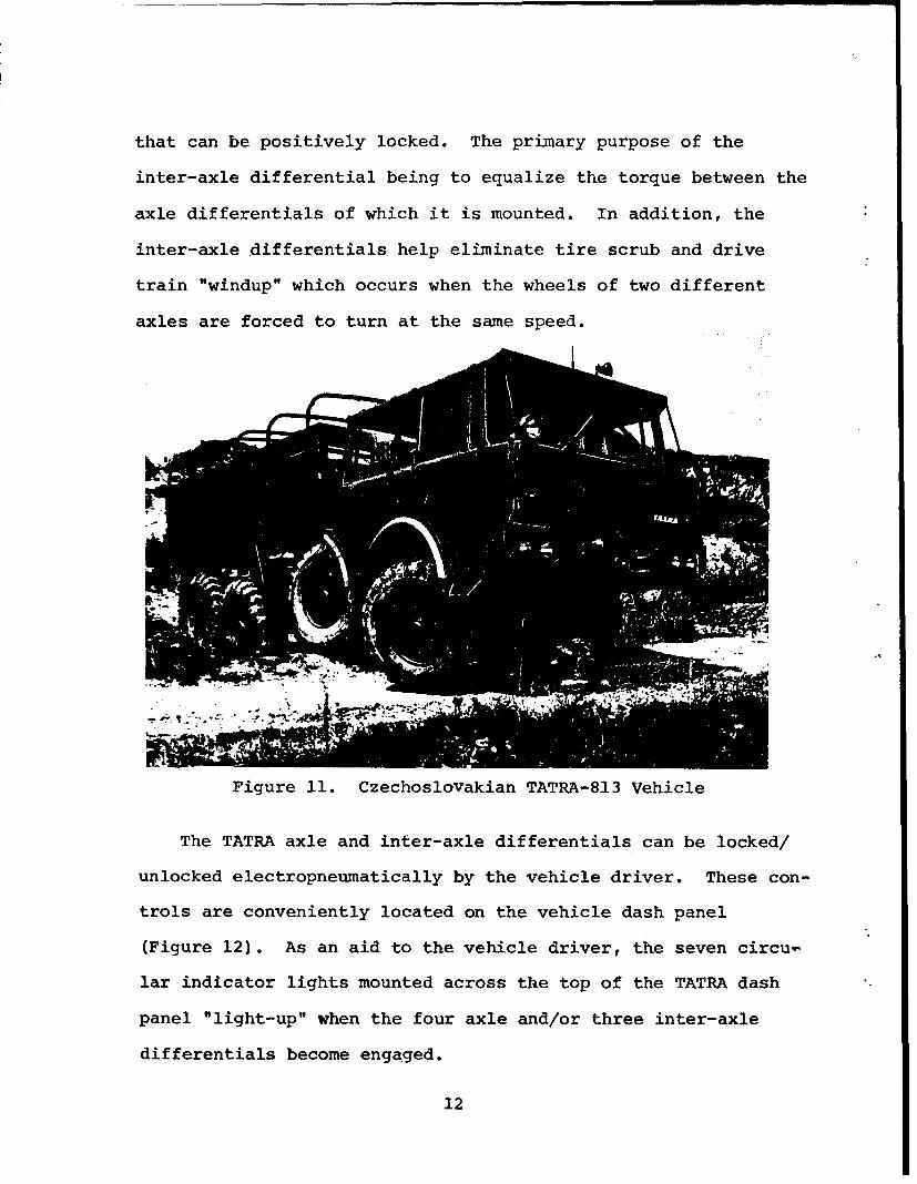
The TATRA axle and inter-axle differentials can be locked/
unlocked electropneumatically by the vehicle driver. These con-
trols are conveniently located on the vehicle dash panel
(Figure 12). As an aid to the vehicle driver, the seven circu-
lar indicator lights mounted across the top of the TATRA dash
panel "light-up" when the four axle and/or three inter-axle
differentials become engaged.
12
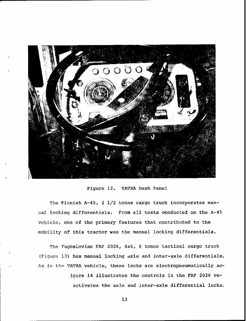
Figure 12. TATRA Dash Panel
The Finnish A-45, 2 1/2 tonne cargo truck incorporates man-
ual locking differentials. From all tests conducted on the A-45
vehicle, one of the primary features that contributed to the
mobility of this tractor was the manual locking differentials.
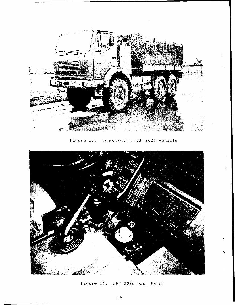
The Yugoslovian FAP 2026, 6x6, 6 tonne tactical cargo truck
(Figure 13) has manual locking axle and inter-axle differentials.
As in the TATRA vehicle, these locks are electropneumatically ac-
igure 14 illustrates the controls in the FAP 2026 ve-
activates the axle and inter-axle differential locks.
13
/t
TF gu r ( 13. Yuqoný;]ovaan PAP 2026 Vehicle
Figure 14. FAP 2026 Dash Panel
14
As with any system incorporated into a tactical vehicle, ul-
timate results are achieved only if the system is properly uti-
lized. When using the manual locking differentials, the vehicle
operator must be selective. Unlike the conventional limited
slip type differentials which are somewhat automatic, the driver
of a vehicle with manual locking differentials must know when,
and when not to activate this system. It can be a very valuable
tool when properly used as an off-road mobility aid.
Independent Swing Axles
One of the primary factors that determines the degree of
mobility a wheeled vehicle will have in adverse terrain is the
amount of tire contact area which is exposed to the terrain.
Assuming that all else is equal, an 8x8 vehicle that is capable
of having all eight tires in contact with the ground in a given
terrain will be more mobile than an 8x8 vehicle that has only
seven tires in contact with the ground. Hence, in comparing a
vehicle with solid axle design to a vehicle with swing axle de-
sign, the swing axle type is not as rigid and is more apt to
follow the terrain profile.
The TATRA-813 tactical cargo truck is designed with independ-
ent swing axles, whereas there are no "U" joints between the
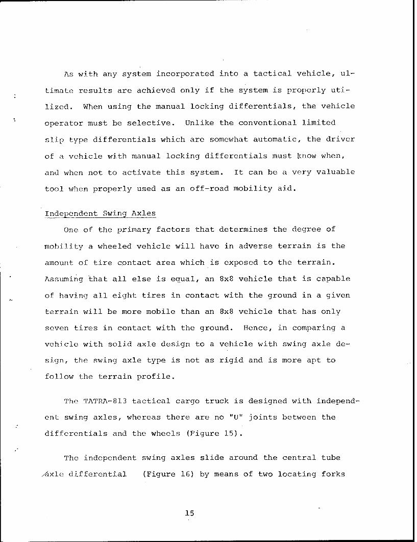
differentials and the wheels (Figure 15).
The independent swing axles slide around the central tube
/Axle differential (Figure 16) by means of two locating forks
15
whereas all suspension reactions are taken up by these forks.
The crown gears attached to the axle, meshes with the pinion
gear within the differential.
Figure 15. TATRA Swing Axle
16

Figure 16. TATRA Axle Differential
In a solid axle design, when the vehicle negotiates an ob-
stacle, the axle (due to its rigid configuration) can make the
vehicle somewhat unstable. If a vehicle with swing axle design
(such as the TATRA-813) were to negotiate this same obstacle,
the vehicles angular displacement would be less.
Despite the fact that the TATRA vehicle is somewhat under-
powered (16.5 lip/Ton), testing has indicated that it is an
extremely mobile vehicle over a variety of adverse terrains.
One of the primary factors accountable for this outstanding
mobility is due to the swing axle configuration.
17
From a ride dynamics standpoint, the TATRA vehicle is very
impressive. A vehicle that displays such exceptional ride
dynamics will have a high "speed made good" over a variety of
adverse terrains.
Auxillary Powered Wheels
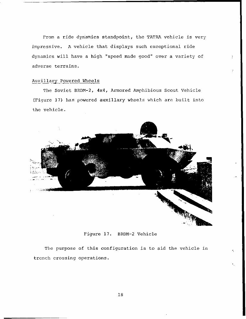
The Soviet BRDM-2, 4x4, Armored Amphibious Scout Vehicle
(Figure 17) has powered auxillary wheels which are built into
the vehicle.
Figure 17. BRDM-2 Vehicle
The purpose of this configuration is to aid the vehicle in
trench crossing operations.
18
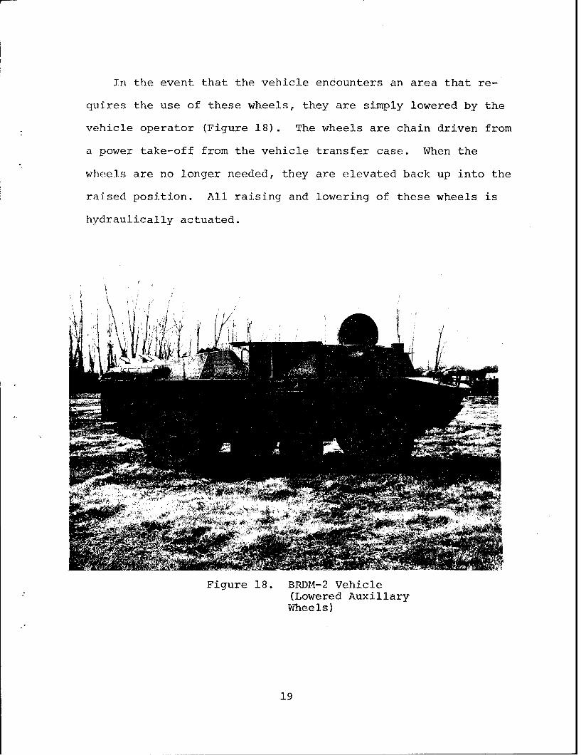
In the event that the vehicle encounters an area that re-
quires the use of these wheels, they are simply lowered by the
vehicle operator (Figure 18). The wheels are chain driven from
a power take-off from the vehicle transfer case. When the
wheels are no longer needed, they are elevated back up into the
raised position. All raising and lowering of these wheels is
hydraulically actuated.
Figure 18. BRDM-2 Vehicle(Lowered AuxillaryWheels)
19
Trench crossing for a wheeled vehicle is normally limited by
the vehicle tire size, wheel base and center of gravity.
However, by utilizing these auxillary powered wheels, the
problem of negotiating trenches is reduced considerably.
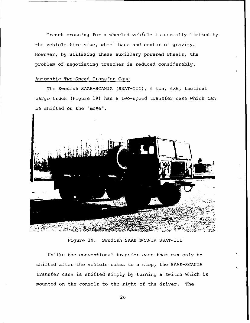
Automatic Two-Speed Transfer Case
The Swedish SAAB-SCANIA (SBAT-III), 6 ton, 6x6, tactical
cargo truck (Figure 19) has a two-speed transfer case which can
be shifted on the "move".
Figure 19. Swedish SAAB SCANIA SBAT-III
Unlike the conventional transfer case that can only be
shifted after the vehicle comes to a stop, the SAAB-SCANIA
transfer case is shifted simply by turning a switch which is
mounted on the console to the right of the driver. The
20
advantage of such a feature can significantly effect the mobil-
ity of a vehicle from the standpoint of "speed made good."
Such a feature allows the vehicle operator to change his mode
of driving from highway to cross-country operation without
bringing the vehicle to a stop by shifting from high to low
range. In addition, it gives the vehicle driver confidence due
to the ease of operation.
Downshifts may be preselected with this control at any
speed, however, the shift does not actually take place until
the vehicle speed drops below 18 Km/Hr and the accelerator
pedal is released.
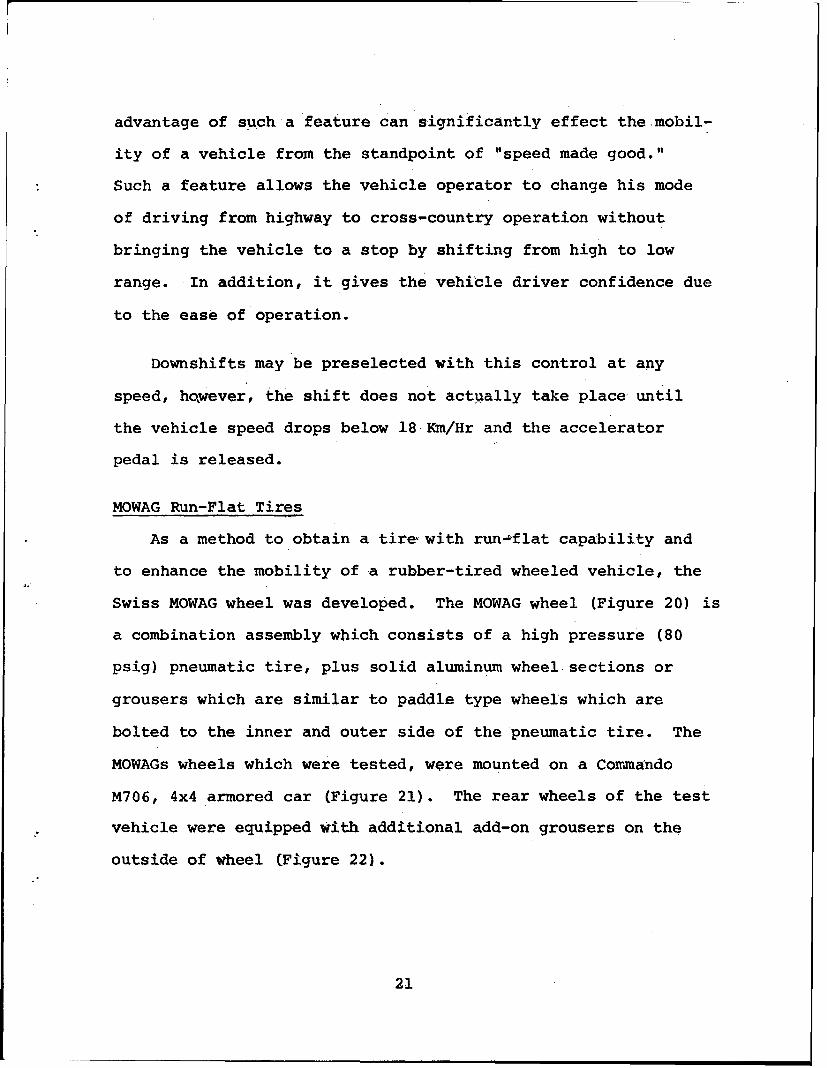
MOWAG Run-Flat Tires
As a method to obtain a tire-with run-,,flat capability and
to enhance the mobility of a rubber-tired wheeled vehicle, the
Swiss MOWAG wheel was developed. The MOWAG wheel (Figure 20) is
a combination assembly which consists of a high pressure (80
psig) pneumatic tire, plus solid aluminum wheel sections or
grousers which are similar to paddle type wheels which are
bolted to the inner and outer side of the pneumatic tire. The
MOWAGs wheels which were tested, were mounted on a Commando
M706, 4x4 armored car (Figure 21). The rear wheels of the test
vehicle were equipped with additional add-on grousers on the
outside of wheel (Figure 22).
21
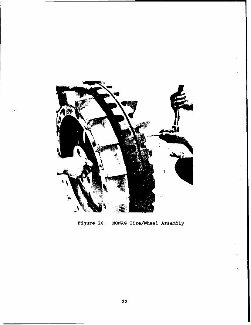
Figure 20. MOWAG Tire/Wheel Assembly
22
Figure 21. M706 Vehicle With MOWAG Wheels
23
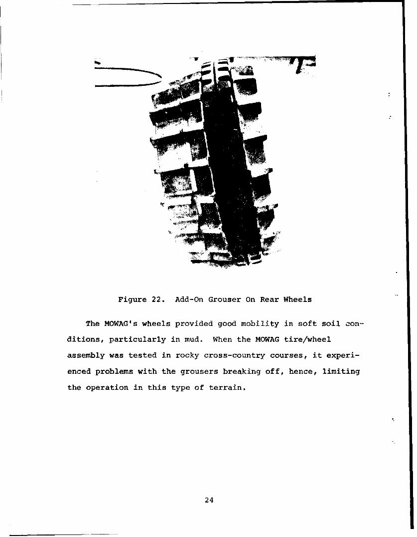
Figure 22. Add-On Grouser On Rear Wheels
The MOWAG's wheels provided good mobility in soft soil con-
ditions, particularly in mud. When the MOWAG tire/wheel
assembly was tested in rocky cross-country courses, it experi-
enced problems with the grousers breaking off, hence, limiting
the operation in this type of terrain.
24
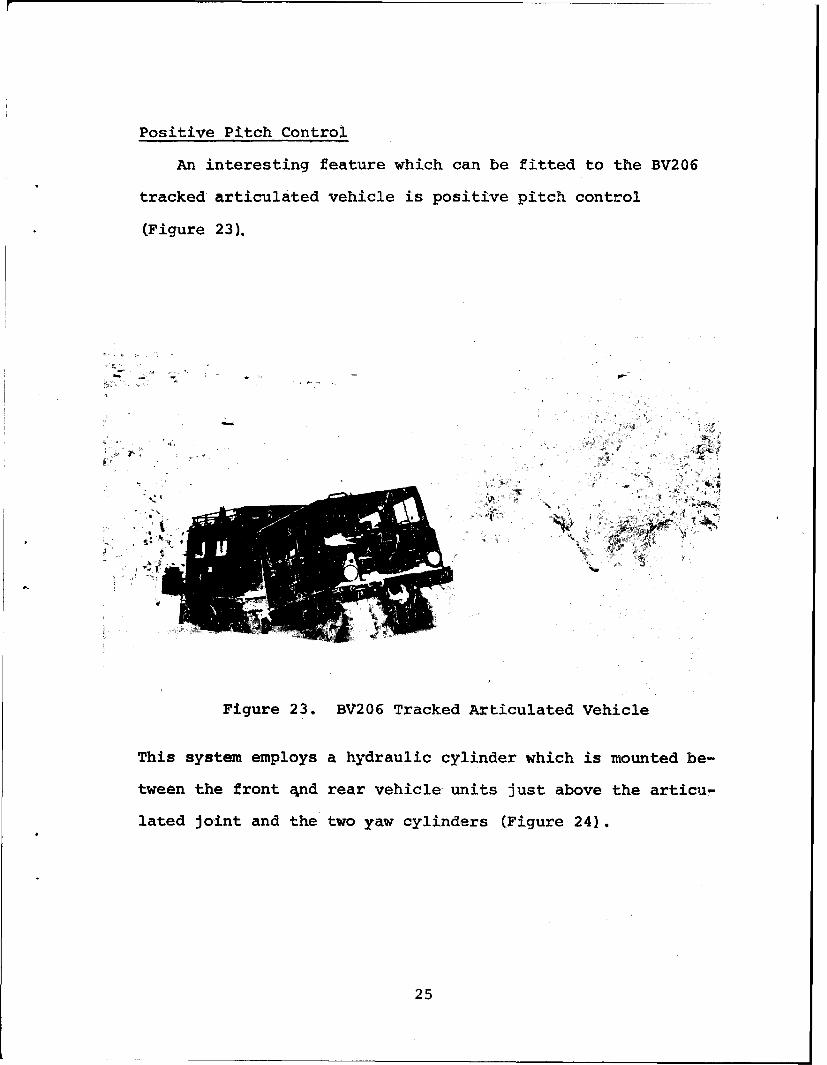
Positive Pitch Control
An interesting feature which can be fitted to the BV206
tracked articulated vehicle is positive pitch control
(Figure 23).
Figure 23. BV206 Tracked Articulated Vehicle
This system employs a hydraulic cylinder which is mounted be-
tween the front 4nd rear vehicle units just above the articu-
lated joint and the two yaw cylinders (Figure 24).
25
JJ
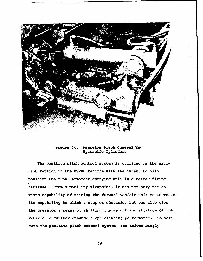
Figure 24. Positive Pitch Control/YawHydraulic Cylinders
The positive pitch control system is utilized on the anti-
tank version of the BV206 vehicle with the intent to help
position the front armament carrying unit in a better firing
attitude. From a mobility viewpoint, it has not only the ob-
vious capability of raising the forward vehicle unit to increase
its capability to climb a step or obstacle, but can also give
the operator a means of shifting the wbight and attitude of the
vehicle to further enhance slope climbing performance. To acti-
vate the positive pitch control system, the driver simply
26
activates a control lever which is located to the left of the
driver seat.
The US Army has conducted several test programs on articu-
lated vehicles which incorporate systems that assist in varying
the pitch between the vehicle units. It is hopeful that the
test and evaluation of the BV206 vehicle with positive pitch
control will enhance this technology base for articulated
vehicle mobility.
Studded Track Shoe
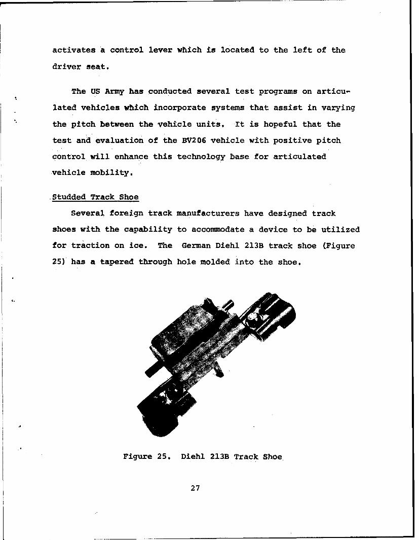
Several foreign track manufacturers have designed track
shoes with the capability to accommodate a device to be utilized
for traction on ice. The German Diehl 213B track shoe (Figure
25) has a tapered through hole molded into the shoe.
Figure 25. Diehl 213B Track Shoe
27
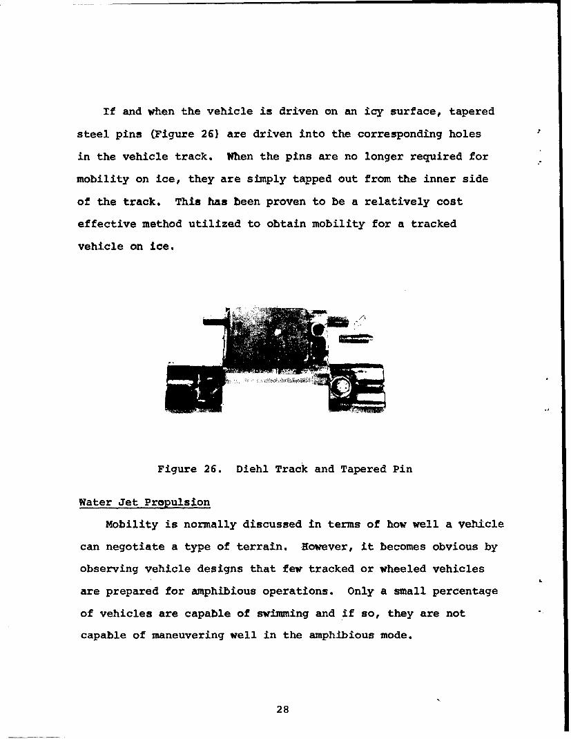
If and when the vehicle is driven on an icy surface, tapered
steel pins (Figure 26) are driven into the corresponding holes
in the vehicle track. When the pins are no longer required for
mobility on ice, they are simply tapped out from the inner side
of the track. This has been proven to be a relatively cost
effective method utilized to obtain mobility for a tracked
vehicle on ice.
Figure 26. Diehl Track and Tapered Pin
Water Jet Propulsion
Mobility is normally discussed in terms of how well a vehicle
can negotiate a type of terrain. However, it becomes obvious by
observing vehicle designs that few tracked or wheeled vehicles
are prepared for amphibious operations. Only a small percentage
of vehicles are capable of swimming and if so, they are not
capable of maneuvering well in the amphibious mode.
28
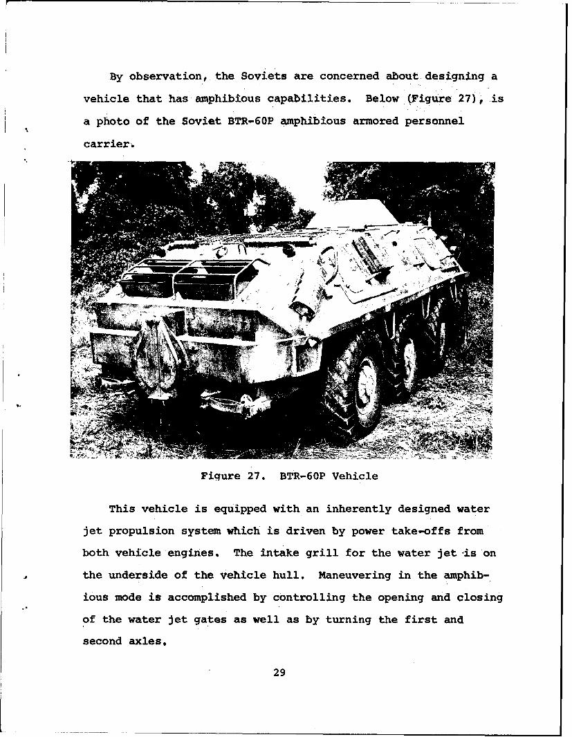
By observation, the Soviets are concerned about designing a
vehicle that has amphibious capabilities. Below (Figure 27)F is
a photo of the Soviet BTR-60P amphibious armored personnel
carrier6
Figure 27. BTR-60P Vehicle
This vehicle is equipped with an inherently designed water
jet propulsion system which is driven by power take-offs from
both vehicle engines. The intake grill for the water jet-is on
the underside of the vehicle hull. Maneuvering in the amphib-
ious mode is accomplished by controlling the opening and closing
of the water jet gates as well as by turning the first and
second axles.
29
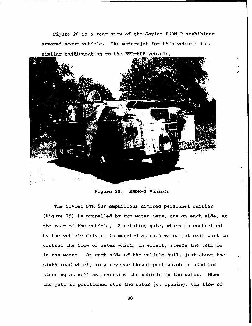
Figure 28 is a rear view of the Soviet BRDM-2 amphibious
armored scout vehicle. The water-jet for this vehicle is a
similar configuration to the BTR-60P vehicle.
VI
Figure 28. BRDM,-2 Vehicle
The Soviet BTR-50P amphibious armored personnel carrier
(Figure 29) is propelled by two water jets, one on each side, at
the rear of the vehicle. A rotating gate, which is controlled
by the vehicle driver, is mounted at each water jet exit port to
control the flow of water which, in effect, steers the vehicle
in the water. On each side of the vehicle hull, just above the
sixth road wheel, is a reverse thrust port which is used for
steering as well as reversing the vehicle in the water. When
the gate is positioned over the water jet opening, the flow of
30
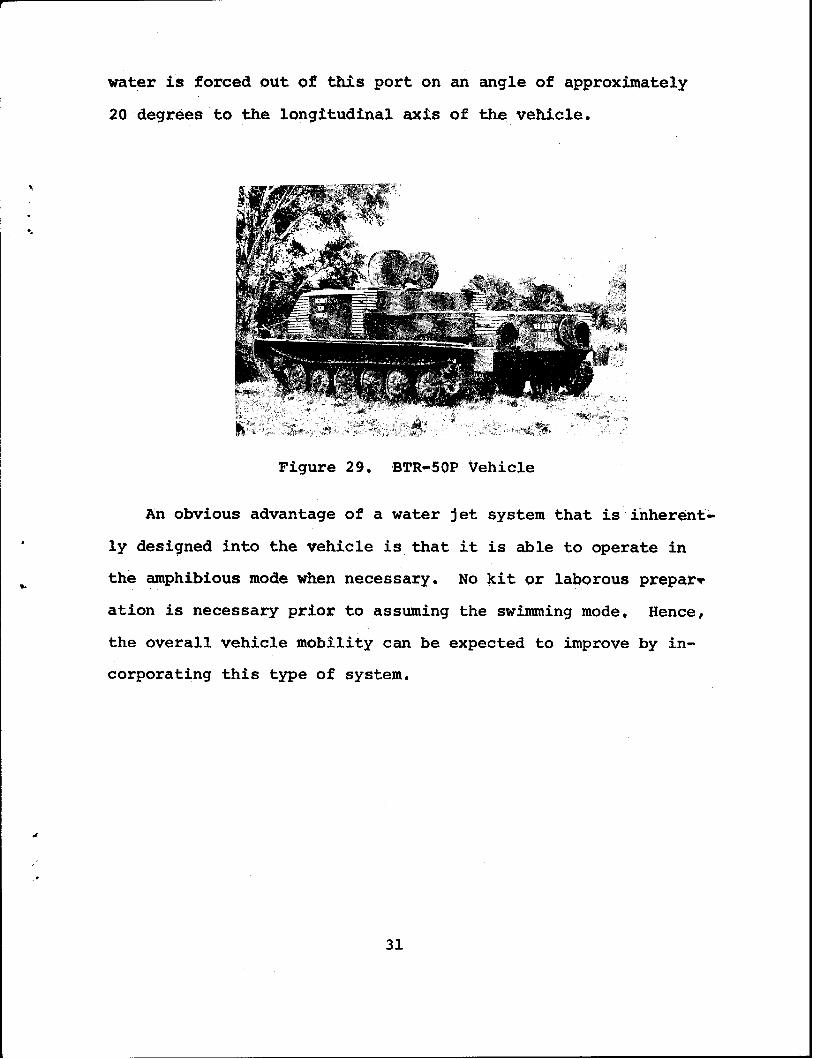
water is forced out of this port on an angle of approximately
20 degrees to the longitudinal axis of the vehicle.
Figure 29. BTR-50P Vehicle
An obvious advantage of a water jet system that is inherent-
ly designed into the vehicle is that it is able to operate in
the amphibious mode when necessary. No kit or laborous preparT
ation is necessary prior to assuming the swimming mode. Hence,
the overall vehicle mobility can be expected to improve by in-
corporating this type of system.
31
SUMMARY
In summary, there are many well proven systems which can be
configured into both tracked and wheeled vehicles which will
enhance overall mobility. If the mobility design requirements
of a vehicle are properly represented in the vehicle develop-
ment stage, it can enhance the probability of obtaining a cost
effective vehicle that performs well. This paper has merely
"scratched the surface" on the numerous systems that could be
incorporated into vehicles to achieve these design objectives.
32


![perceelnummer 0644/00D000 [33011F0644/00D000] …...Resultaat opvraging perceel gelegen in Ieper afdeling IEPER 1 AFD, sectie F met perceelnummer 0644/00D000 [33011F0644/00D000] Beschrijving](https://img.pdfslide.net/doc/110x75/5f883dc5f7c4d05ebf71bcd2/perceelnummer-064400d000-33011f064400d000-resultaat-opvraging-perceel-gelegen.jpg)