Embed Size (px)
Citation preview

UNITED STATES DEPARTMENT OF COMMERCE NATIONAL OCEANIC & ATMOSPHERIC ADMINISTRATION
NATIONAL OCEAN SERVICE NATIONAL GEODETIC SURVEY
INTERNATIONAL EARTH ROTATION & REFERENCE SYSTEM SERVICES
ST. CROIX, USVI LOCAL SITE SURVEY REPORT
Kendall L. Fancher
Benjamin Erickson
Dates of Data Collection: May, 2017
Date of Report: July, 2017

i
Introduction ..................................................................................................................................... 3
1. Site Description ........................................................................................................................... 3
2. Instrumentation ........................................................................................................................... 3
2.1. Tacheometers .................................................................................................................... 3
2.1.1. Description ............................................................................................................. 3
2.1.2. Calibrations ............................................................................................................. 3
2.1.3. Auxiliary Equipment .............................................................................................. 4
2.2. GPS Units ......................................................................................................................... 4
2.2.1. Receivers ................................................................................................................ 4
2.2.2. Antennas ................................................................................................................. 4
2.2.3. Analysis software, mode of operation .................................................................... 4
2.3. Leveling ............................................................................................................................ 4
2.3.1. Leveling Instruments .............................................................................................. 4
2.3.2. Leveling Staffs ........................................................................................................ 4
2.3.3. Checks carried out before measurements ............................................................... 4
2.4. Tripods .............................................................................................................................. 4
2.5. Forced Centering Devices ................................................................................................. 5
2.6. Targets, Reflectors ............................................................................................................ 6
3. Measurement Setup ..................................................................................................................... 6
3.1. Ground Network ............................................................................................................... 6
3.1.1. Listing ..................................................................................................................... 6
3.1.2. Map of Network ..................................................................................................... 8
3.2. Representation of Technique Reference Points ................................................................ 9
3.2.1. VLBI ....................................................................................................................... 9
3.2.2. GPS ......................................................................................................................... 9
4. Observations ............................................................................................................................. 10
4.1. Conventional Survey ...................................................................................................... 10
4.2. Leveling .......................................................................................................................... 11
4.3. GPS ................................................................................................................................. 11
4.4. General Comments ......................................................................................................... 12
5. Terrestrial Survey...................................................................................................................... 14
5.1. Analysis software ............................................................................................................ 14
5.1.2. Topocentric Coordinates and Covariance ............................................................ 14
5.1.3. Correlation Matrix ................................................................................................ 14

ii
5.2. GPS Observations ........................................................................................................... 14
5.3. Additional Parameters .................................................................................................... 14
5.3.1. VLBA antenna Axis Offset Computation ............................................................ 14
5.3.2. GPS Antenna Reference Point Offset from Instrument Mark Computation ........ 15
5.4. Transformation ............................................................................................................... 15
5.5. Description of SINEX generation ................................................................................... 15
5.6. Discussion of Results ...................................................................................................... 15
6. Planning Aspects ....................................................................................................................... 18
7. References ................................................................................................................................. 18
7.1. Name of person(s) responsible for observations ............................................................ 18
7.2. Name of person(s) responsible for analysis .................................................................... 18
7.3. Location of observation data and results archive ........................................................... 19
Attachment: SINEX Format ........................................................................................................ 20
3
Introduction
During May 2017, the National Geodetic Survey conducted a high precision local site survey at the
National Radio Astronomy Observatory’s Very Long Baseline Array site located in St. Croix, US Virgin
Islands. Data collection consisted of coordinate measurement procedures incorporating absolute laser
tracker and Global Positioning System (GPS) observations using survey grade instrumentation. The
primary objective of the survey was to establish high precision local ties, referenced to the International
Terrestrial Reference Frame (ITRF2014), for technique instrument reference marks associated with a
radio telescope, sometimes used for Very Long Baseline Interferometry (VLBI) and a Global Navigation
Satellite System (GNSS) antenna. This report documents the instrumentation and methodologies used to
collect the geo-spatial data set and data reduction and analysis procedures used to compute the local ties.
1. Site Description
Site Name: Sainte Croix (USVI)
Country Name: UNITED STATES OF AMERICA
Longitude: E 295° 25’
Latitude: N 17° 26’
Tectonic plate: CARB
SGT
Instrument Name DOMES# Description/a.k.a.
VLBI CRO1 43201M001 Instrument Reference Mark
GPS CROA GPS Antenna Reference Point
GPS CRO2 GPS Antenna Reference Point
VLBI 7615 43201S001 Conventional Reference Point Table 1 – Space Geodetic Technique Instruments (SGT) located at the site.
2. Instrumentation
2.1. Tacheometers
2.1.1. Description
Leica AT402 (Absolute Laser Tracking system)
S/N: 392045
Specifications
Angular measurement uncertainty of instrument: ± 0.5”
Combined uncertainty of distance measurement throughout range of instrument: +/- 0.014 mm
2.1.2. Calibrations
Leica AT402, serial number 392045, certified by Leica Geosystem AG Heerbrugg,
Switzerland on 08/28/2013
4
2.1.3. Auxiliary Equipment
Wild NL Collimator, S/N: 40145
Pointing accuracy, 1: 200,000
Leica ATC meteo-station, S/N D214.00.000.002
Accuracy:
Air temperature +/- 0.30 C
Pressure +/- 1 hPa
Relative Humidity +/- 5%
2.2. GPS Units
2.2.1. Receivers
Trimble NetR5, P/N: 62800-00, S/Ns: 4619K01307, 4624K01647, and 4624K01631
Specifications for Static GPS Surveying:
Horizontal: +/- 5 mm + 0.5 ppm RMS
Vertical: +/- 5 mm + 1 ppm RMS
2.2.2. Antennas
Topcon GPS/GLONASS/Galileo choke ring antenna, model CR-G3, P/N: 1-044301-01
S/Ns 383-1614, -1613 and -1628
2.2.3. Analysis software, mode of operation
Post-processing and adjustment were undertaken using NGS’s Online Positioning User Service
(OPUS) Projects, an interactive web page. OPUS Projects uses as an underlying multi-baseline
processor, NGS’s Program for Adjustment of GPS Ephemerides (PAGES) software.
2.3. Leveling
2.3.1. Leveling Instruments
No leveling instruments used during the execution of this survey.
2.3.2. Leveling Staffs
No leveling equipment used during the execution of this survey.
2.3.3. Checks carried out before measurements
Not applicable
2.4. Tripods
Standard wooden surveying tripods, with collapsible legs, used to support surveying instrumentation
centered over all permanent ground network marks.
5
2.5. Forced Centering Devices
A wild slip leg type wooden tripod, incorporating a Leica GDF321 tribrach and standard tribrach
adapter were used to support target/reflectors at all ground control marks. Tripod tribrachs were
plumbed over ground control mark reference points using a Wild NL Collimator, then “leveled up”
using a Leica GZR3 carrier with longitudinal level vial. For all ground control marks, the reference
point is considered to be the bottom center of a 0.001 m drill hole near the center of the survey disk.
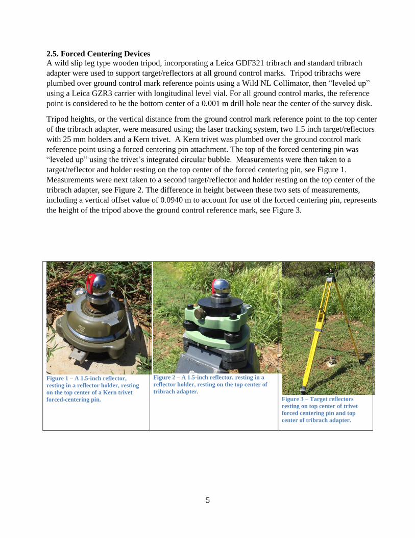
Tripod heights, or the vertical distance from the ground control mark reference point to the top center
of the tribrach adapter, were measured using; the laser tracking system, two 1.5 inch target/reflectors
with 25 mm holders and a Kern trivet. A Kern trivet was plumbed over the ground control mark
reference point using a forced centering pin attachment. The top of the forced centering pin was
“leveled up” using the trivet’s integrated circular bubble. Measurements were then taken to a
target/reflector and holder resting on the top center of the forced centering pin, see Figure 1.
Measurements were next taken to a second target/reflector and holder resting on the top center of the
tribrach adapter, see Figure 2. The difference in height between these two sets of measurements,
including a vertical offset value of 0.0940 m to account for use of the forced centering pin, represents
the height of the tripod above the ground control reference mark, see Figure 3.
Figure 1 – A 1.5-inch reflector,
resting in a reflector holder, resting
on the top center of a Kern trivet
forced-centering pin.
Figure 2 – A 1.5-inch reflector, resting in a
reflector holder, resting on the top center of
tribrach adapter. Figure 3 – Target reflectors
resting on top center of trivet
forced centering pin and top
center of tribrach adapter.
6
2.6. Targets, Reflectors and Accessories
Leica Break Resistant 1.5-inch reflector, part # 576-244
Centering of Optics: < ± 0.01mm
Leica Tripod Adapter, part # 575-837
Leica Reflector Holder 1.5-inch, part # 577-126
Leica Reflector Holder 1.5-inch, part # 577-104
All absolute laser tracker measurements were taken to Leica 1.5-inch Break Resistant Reflectors,
serving as both target and reflector. Reflectors were affixed to tribrachs using a combination of a
Leica 1.5-inch reflector holder and Leica Tripod Adapter attached to a standard tribrach adapter.
3. Measurement Setup
3.1. Ground Network
Ground network marks are monumented for future reference. The terrestrial survey ties them
together in a local coordinate system using high precision horizontal/zenith angles and distance
measurements. Non-monumented, or temporary marks, (TP01, TP02 and TP03) were used this
survey to facilitate alignment of the absolute tracker measurements.
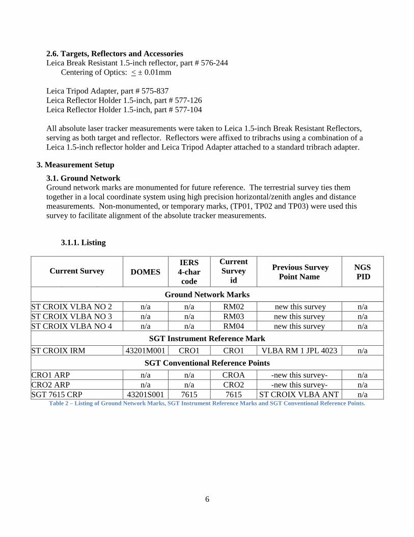
3.1.1. Listing
Current Survey
Main-Scheme Marks
DOMES
IERS
4-char
code
Current
Survey
id
Code
Previous Survey
Point Name
NGS
PID
Ground Network Marks
ST CROIX VLBA NO 2 n/a n/a RM02 new this survey n/a
ST CROIX VLBA NO 3 n/a n/a RM03 new this survey n/a
ST CROIX VLBA NO 4 n/a n/a RM04 new this survey n/a
SGT Instrument Reference Mark
ST CROIX IRM 43201M001 CRO1 CRO1 VLBA RM 1 JPL 4023 n/a
SGT Conventional Reference Points
CRO1 ARP n/a n/a CROA -new this survey- n/a
CRO2 ARP n/a n/a CRO2 -new this survey- n/a
SGT 7615 CRP 43201S001 7615 7615 ST CROIX VLBA ANT
7234
n/a Table 2 – Listing of Ground Network Marks, SGT Instrument Reference Marks and SGT Conventional Reference Points.
7
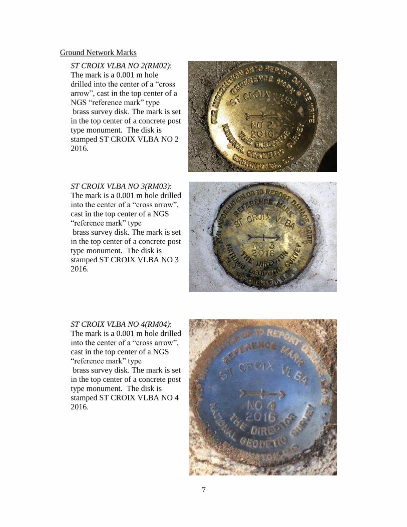
Ground Network Marks
ST CROIX VLBA NO 2(RM02):
The mark is a 0.001 m hole
drilled into the center of a “cross
arrow”, cast in the top center of a
NGS “reference mark” type
brass survey disk. The mark is set
in the top center of a concrete post
type monument. The disk is
stamped ST CROIX VLBA NO 2
2016.
ST CROIX VLBA NO 3(RM03):
The mark is a 0.001 m hole drilled
into the center of a “cross arrow”,
cast in the top center of a NGS
“reference mark” type
brass survey disk. The mark is set
in the top center of a concrete post
type monument. The disk is
stamped ST CROIX VLBA NO 3
2016.
ST CROIX VLBA NO 4(RM04):
The mark is a 0.001 m hole drilled
into the center of a “cross arrow”,
cast in the top center of a NGS
“reference mark” type
brass survey disk. The mark is set
in the top center of a concrete post
type monument. The disk is
stamped ST CROIX VLBA NO 4
2016.
8
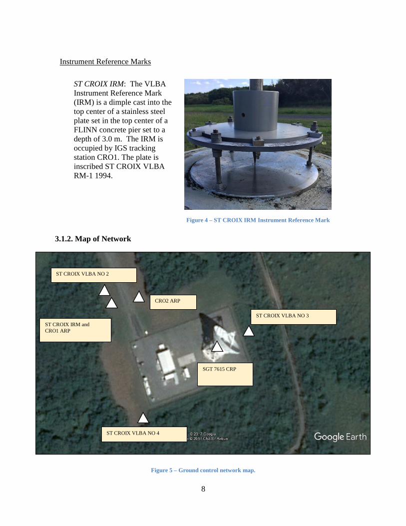
Instrument Reference Marks
ST CROIX IRM: The VLBA
Instrument Reference Mark
(IRM) is a dimple cast into the
top center of a stainless steel
plate set in the top center of a
FLINN concrete pier set to a
depth of 3.0 m. The IRM is
occupied by IGS tracking
station CRO1. The plate is
inscribed ST CROIX VLBA
RM-1 1994.
Figure 4 – ST CROIX IRM Instrument Reference Mark
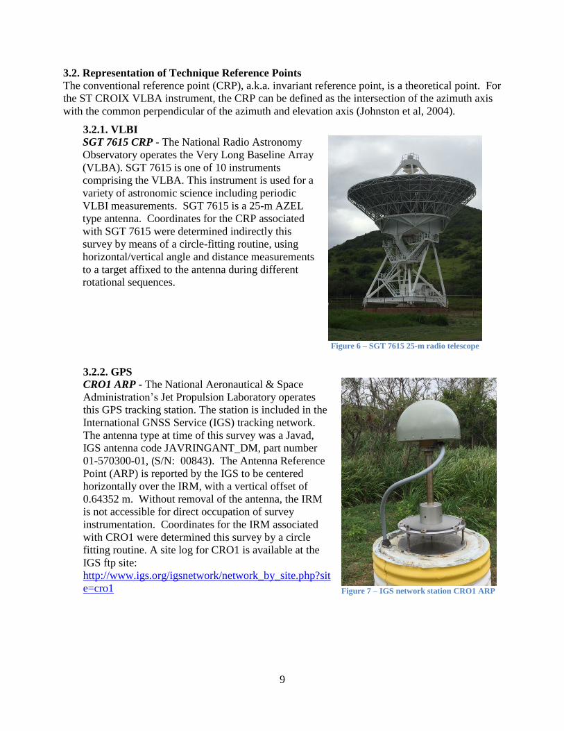
3.1.2. Map of Network
Figure 5 – Ground control network map.
ST CROIX VLBA NO 2
ST CROIX VLBA NO 3
ST CROIX VLBA NO 4
ST CROIX IRM and CRO1 ARP
CRO2 ARP
SGT 7615 CRP
9
3.2. Representation of Technique Reference Points
The conventional reference point (CRP), a.k.a. invariant reference point, is a theoretical point. For
the ST CROIX VLBA instrument, the CRP can be defined as the intersection of the azimuth axis
with the common perpendicular of the azimuth and elevation axis (Johnston et al, 2004).
3.2.1. VLBI
SGT 7615 CRP - The National Radio Astronomy
Observatory operates the Very Long Baseline Array
(VLBA). SGT 7615 is one of 10 instruments
comprising the VLBA. This instrument is used for a
variety of astronomic science including periodic
VLBI measurements. SGT 7615 is a 25-m AZEL
type antenna. Coordinates for the CRP associated
with SGT 7615 were determined indirectly this
survey by means of a circle-fitting routine, using
horizontal/vertical angle and distance measurements
to a target affixed to the antenna during different
rotational sequences.
Figure 6 – SGT 7615 25-m radio telescope
3.2.2. GPS
CRO1 ARP - The National Aeronautical & Space
Administration’s Jet Propulsion Laboratory operates
this GPS tracking station. The station is included in the
International GNSS Service (IGS) tracking network.
The antenna type at time of this survey was a Javad,
IGS antenna code JAVRINGANT_DM, part number
01-570300-01, (S/N: 00843). The Antenna Reference
Point (ARP) is reported by the IGS to be centered
horizontally over the IRM, with a vertical offset of
0.64352 m. Without removal of the antenna, the IRM
is not accessible for direct occupation of survey
instrumentation. Coordinates for the IRM associated
with CRO1 were determined this survey by a circle
fitting routine. A site log for CRO1 is available at the
IGS ftp site:
http://www.igs.org/igsnetwork/network_by_site.php?sit
e=cro1
Figure 7 – IGS network station CRO1 ARP
10
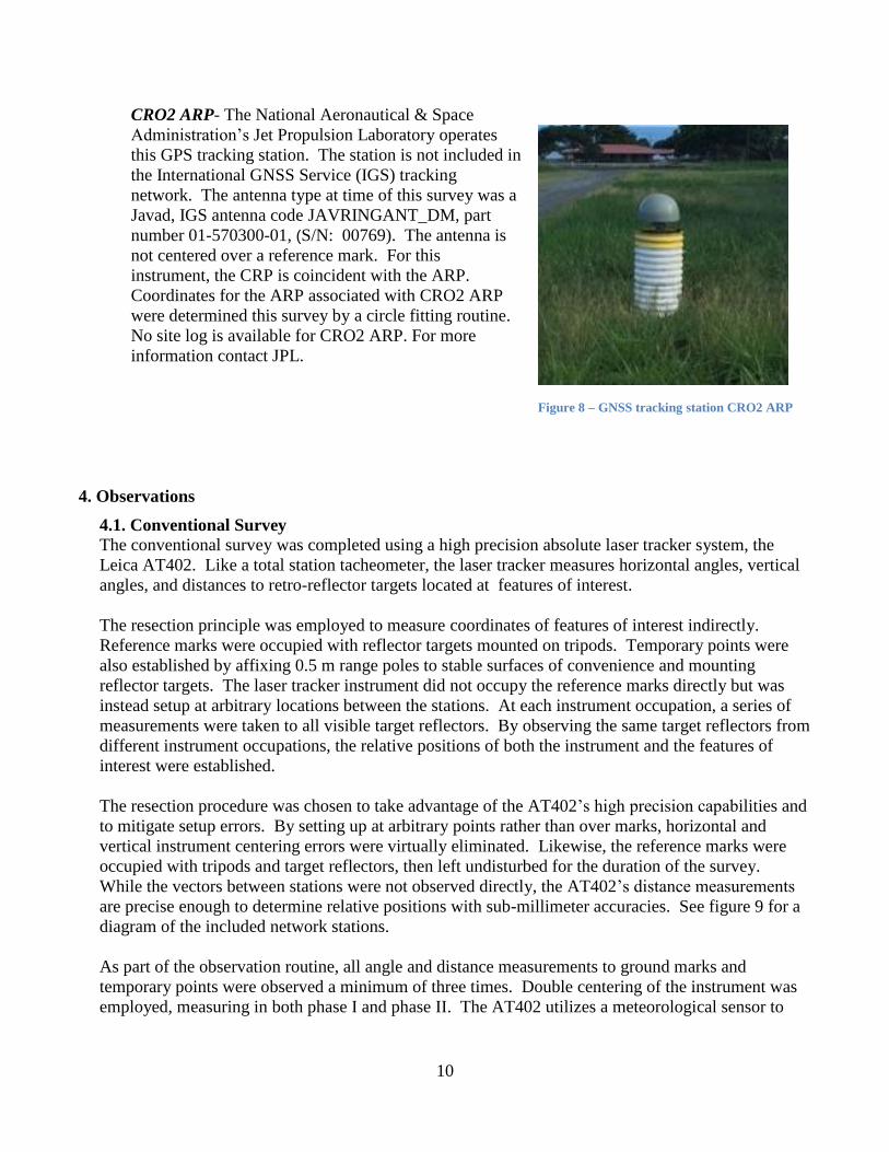
CRO2 ARP- The National Aeronautical & Space
Administration’s Jet Propulsion Laboratory operates
this GPS tracking station. The station is not included in
the International GNSS Service (IGS) tracking
network. The antenna type at time of this survey was a
Javad, IGS antenna code JAVRINGANT_DM, part
number 01-570300-01, (S/N: 00769). The antenna is
not centered over a reference mark. For this
instrument, the CRP is coincident with the ARP.
Coordinates for the ARP associated with CRO2 ARP
were determined this survey by a circle fitting routine.
No site log is available for CRO2 ARP. For more
information contact JPL.
Figure 8 – GNSS tracking station CRO2 ARP
4. Observations
4.1. Conventional Survey
The conventional survey was completed using a high precision absolute laser tracker system, the
Leica AT402. Like a total station tacheometer, the laser tracker measures horizontal angles, vertical
angles, and distances to retro-reflector targets located at features of interest.
The resection principle was employed to measure coordinates of features of interest indirectly.
Reference marks were occupied with reflector targets mounted on tripods. Temporary points were
also established by affixing 0.5 m range poles to stable surfaces of convenience and mounting
reflector targets. The laser tracker instrument did not occupy the reference marks directly but was
instead setup at arbitrary locations between the stations. At each instrument occupation, a series of
measurements were taken to all visible target reflectors. By observing the same target reflectors from
different instrument occupations, the relative positions of both the instrument and the features of
interest were established.
The resection procedure was chosen to take advantage of the AT402’s high precision capabilities and
to mitigate setup errors. By setting up at arbitrary points rather than over marks, horizontal and
vertical instrument centering errors were virtually eliminated. Likewise, the reference marks were
occupied with tripods and target reflectors, then left undisturbed for the duration of the survey.
While the vectors between stations were not observed directly, the AT402’s distance measurements
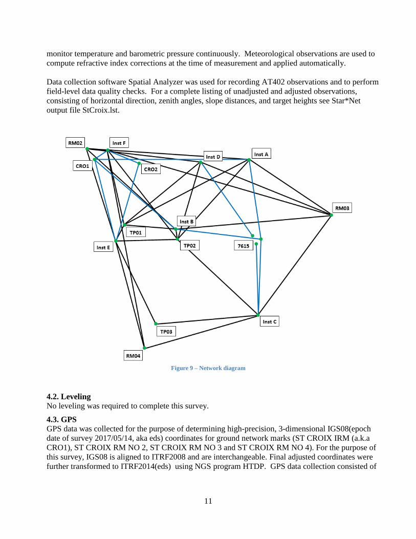
are precise enough to determine relative positions with sub-millimeter accuracies. See figure 9 for a
diagram of the included network stations.
As part of the observation routine, all angle and distance measurements to ground marks and
temporary points were observed a minimum of three times. Double centering of the instrument was
employed, measuring in both phase I and phase II. The AT402 utilizes a meteorological sensor to
11
monitor temperature and barometric pressure continuously. Meteorological observations are used to
compute refractive index corrections at the time of measurement and applied automatically.
Data collection software Spatial Analyzer was used for recording AT402 observations and to perform
field-level data quality checks. For a complete listing of unadjusted and adjusted observations,
consisting of horizontal direction, zenith angles, slope distances, and target heights see Star*Net
output file StCroix.lst.
Figure 9 – Network diagram
4.2. Leveling
No leveling was required to complete this survey.
4.3. GPS
GPS data was collected for the purpose of determining high-precision, 3-dimensional IGS08(epoch
date of survey 2017/05/14, aka eds) coordinates for ground network marks (ST CROIX IRM (a.k.a
CRO1), ST CROIX RM NO 2, ST CROIX RM NO 3 and ST CROIX RM NO 4). For the purpose of
this survey, IGS08 is aligned to ITRF2008 and are interchangeable. Final adjusted coordinates were
further transformed to ITRF2014(eds) using NGS program HTDP. GPS data collection consisted of

12
simultaneous and long-session observations conducted over multiple days. GPS-derived coordinates
for these three marks were used to align or transform the local terrestrial network to ITRF2014(eds).
4.4. General Comments
As noted earlier, determining the local coordinates of the SGT 7615 CRP was achieved using an
indirect approach. The “circle fit” theory is described herein. A point, as it revolves about an axis,
scribes a perfect arc. The arc defines a perfect circle and a plane simultaneously. The axis can then
be seen as it passes through the center of the circle, orthogonal to the plane. By assigning coordinates
to the points observed along an arc rotated about an axis, one can assign parameters to the axis
relative to an established local coordinate system.
Tracker measurements project coordinates from the local ground network to a target reflector
attached to a geodetic technique instrument as it moves about the instrument’s axis, thereby providing
the necessary information to locate a single axis. The same procedure must be done for the opposing
axis of the instrument in the same local reference frame. The point along the primary axis that is
orthogonal to the secondary axis is the CRP associated with the SGT.
In practice, precise observations involving a single target reflector secured to the telescope,
measurements from at least two instrument locations, and numerous measurements per axis serve to
ensure a millimeter level of positional precision is achieved. SGT 7615 CRP was determined in this
manner.
Local coordinates for; ST CROIX IRM, CRO1 ARP and CRO2 ARP were determined using a circle
fitting routine. For ST CROIX IRM, 3-dimensional measurements were taken to a target reflector at
multiple points along the circumference of an antenna offset pin resting in the reference point of the
IRM (see figure 10). A sufficient number of points were measured around the circumference of the
offset pin to scribe a circle in space. Corrections were applied to account for reflector and holder
offset constants. Coordinates corresponding to the center of the scribed circle and theoretically the
center of the IRM reference point were computed. Measurements were taken from at least two
independent locations for redundancy.
13
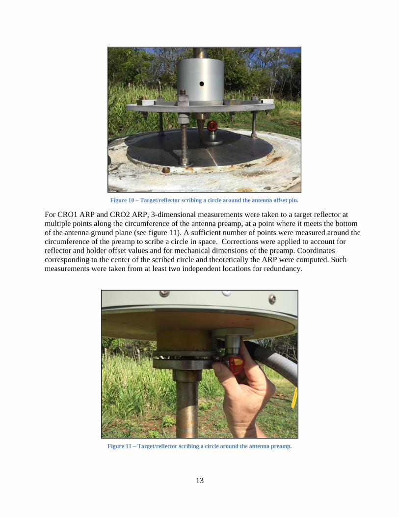
Figure 10 – Target/reflector scribing a circle around the antenna offset pin.
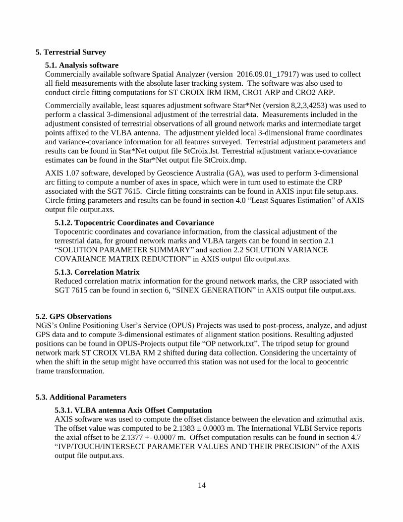
For CRO1 ARP and CRO2 ARP, 3-dimensional measurements were taken to a target reflector at
multiple points along the circumference of the antenna preamp, at a point where it meets the bottom
of the antenna ground plane (see figure 11). A sufficient number of points were measured around the
circumference of the preamp to scribe a circle in space. Corrections were applied to account for
reflector and holder offset values and for mechanical dimensions of the preamp. Coordinates
corresponding to the center of the scribed circle and theoretically the ARP were computed. Such
measurements were taken from at least two independent locations for redundancy.
Figure 11 – Target/reflector scribing a circle around the antenna preamp.
14
5. Terrestrial Survey
5.1. Analysis software
Commercially available software Spatial Analyzer (version 2016.09.01_17917) was used to collect
all field measurements with the absolute laser tracking system. The software was also used to
conduct circle fitting computations for ST CROIX IRM IRM, CRO1 ARP and CRO2 ARP.
Commercially available, least squares adjustment software Star*Net (version 8,2,3,4253) was used to
perform a classical 3-dimensional adjustment of the terrestrial data. Measurements included in the
adjustment consisted of terrestrial observations of all ground network marks and intermediate target
points affixed to the VLBA antenna. The adjustment yielded local 3-dimensional frame coordinates
and variance-covariance information for all features surveyed. Terrestrial adjustment parameters and
results can be found in Star*Net output file StCroix.lst. Terrestrial adjustment variance-covariance
estimates can be found in the Star*Net output file StCroix.dmp.
AXIS 1.07 software, developed by Geoscience Australia (GA), was used to perform 3-dimensional
arc fitting to compute a number of axes in space, which were in turn used to estimate the CRP
associated with the SGT 7615. Circle fitting constraints can be found in AXIS input file setup.axs.
Circle fitting parameters and results can be found in section 4.0 “Least Squares Estimation” of AXIS
output file output.axs.
5.1.2. Topocentric Coordinates and Covariance
Topocentric coordinates and covariance information, from the classical adjustment of the
terrestrial data, for ground network marks and VLBA targets can be found in section 2.1
“SOLUTION PARAMETER SUMMARY” and section 2.2 SOLUTION VARIANCE
COVARIANCE MATRIX REDUCTION” in AXIS output file output.axs.
5.1.3. Correlation Matrix
Reduced correlation matrix information for the ground network marks, the CRP associated with
SGT 7615 can be found in section 6, “SINEX GENERATION” in AXIS output file output.axs.
5.2. GPS Observations
NGS’s Online Positioning User’s Service (OPUS) Projects was used to post-process, analyze, and adjust
GPS data and to compute 3-dimensional estimates of alignment station positions. Resulting adjusted
positions can be found in OPUS-Projects output file “OP network.txt”. The tripod setup for ground
network mark ST CROIX VLBA RM 2 shifted during data collection. Considering the uncertainty of
when the shift in the setup might have occurred this station was not used for the local to geocentric
frame transformation.
5.3. Additional Parameters
5.3.1. VLBA antenna Axis Offset Computation
AXIS software was used to compute the offset distance between the elevation and azimuthal axis.
The offset value was computed to be 2.1383 ± 0.0003 m. The International VLBI Service reports
the axial offset to be 2.1377 +- 0.0007 m. Offset computation results can be found in section 4.7
“IVP/TOUCH/INTERSECT PARAMETER VALUES AND THEIR PRECISION” of the AXIS
output file output.axs.
15
5.3.2. GPS Antenna Reference Point Offset from Instrument Mark Computation
NGS Program INVERS3D was used to compute offset values from ST CROIX IRM to CRO1
ARP. Final coordinates for these marks, provided in Table 5, were used as input. Offset values
were computed to be delta north 0.0003 m, delta east -0.0009 m and delta up 0.6435 m. The IGS
reported offset was held as a constraint during the least squares adjustment of the terrestrial
network data. Without removal of the antenna, the length of the offset pin resting inside of the
IRM dimple could not be measured directly during the survey. The IGS reports the offset values to
be delta north 0.000 m, delta east 0.000 m and delta up 0.6435 m (offset pin constant).
5.4. Transformation
Local tie vectors from the terrestrial survey were accurately aligned, or transformed, from a geodetic
frame to ITRF2014(eds) using AXIS software . For the alignment, AXIS requires coordinates in the
desired reference frame and epoch date at a minimum of three co-observed sites (ST CROIX IRM,
ST CROIX RM 3 and ST CROIX RM 4). The spatial integrity of the terrestrial survey is maintained
throughout the transformation process. Transformation parameters and results can be found in
section 3. “APRIORI FRAME ALIGNMENT“in the AXIS output file output.axs.
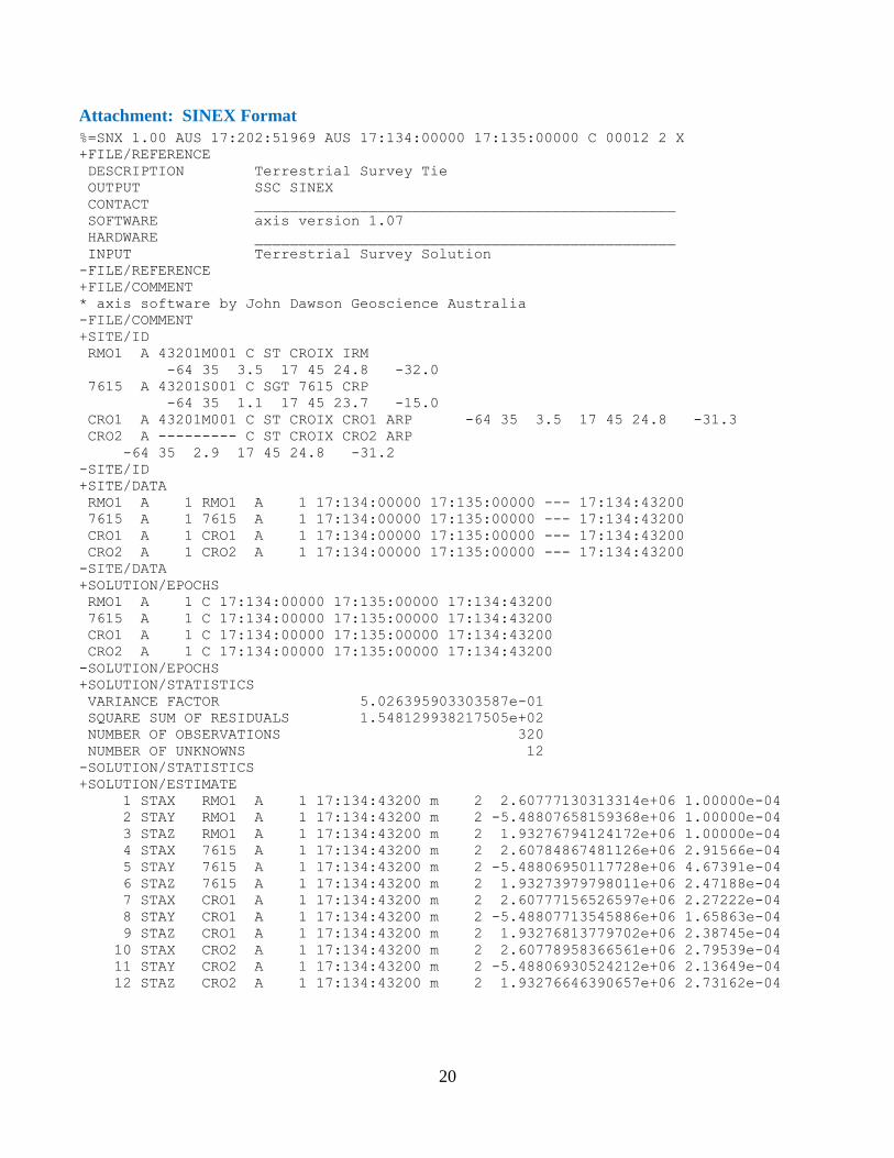
5.5. Description of SINEX generation
AXIS was used to generate a final solution output file in SINEX format with full variance-covariance
matrix information. The following SINEX file naming convention, adopted by GSA for local survey
data, was also used for this survey.
XXXNNNNYYMMFV.SNX
Where:
XXX is a three-character organization designation
NNNN is a four-character site designation
YY is the year of the survey
MM is the month of the survey
F is the frame code (G for global, L for local)
V is the file version
Axis generated SINEX file NGSCRO11705GA.snx is found in the Attachment: SINEX File.
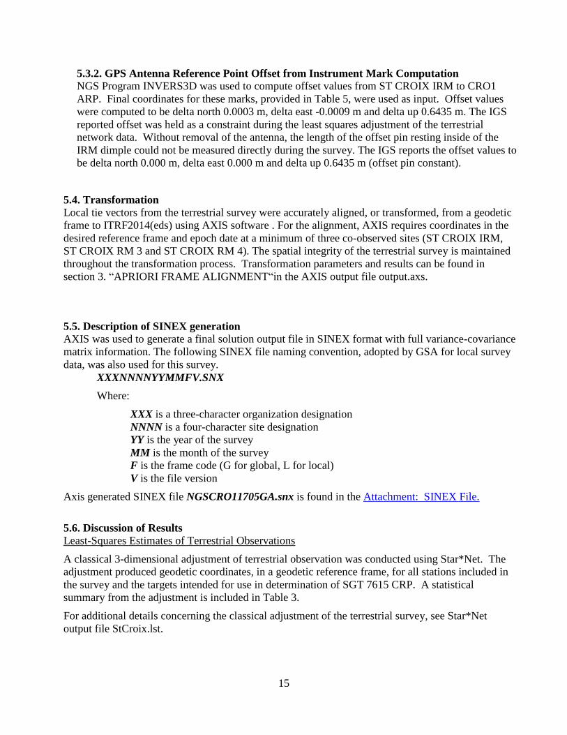
5.6. Discussion of Results
Least-Squares Estimates of Terrestrial Observations
A classical 3-dimensional adjustment of terrestrial observation was conducted using Star*Net. The
adjustment produced geodetic coordinates, in a geodetic reference frame, for all stations included in
the survey and the targets intended for use in determination of SGT 7615 CRP. A statistical
summary from the adjustment is included in Table 3.
For additional details concerning the classical adjustment of the terrestrial survey, see Star*Net
output file StCroix.lst.
16
Table 3 – Terrestrial survey classical 3-dimensional adjustment statistical summary
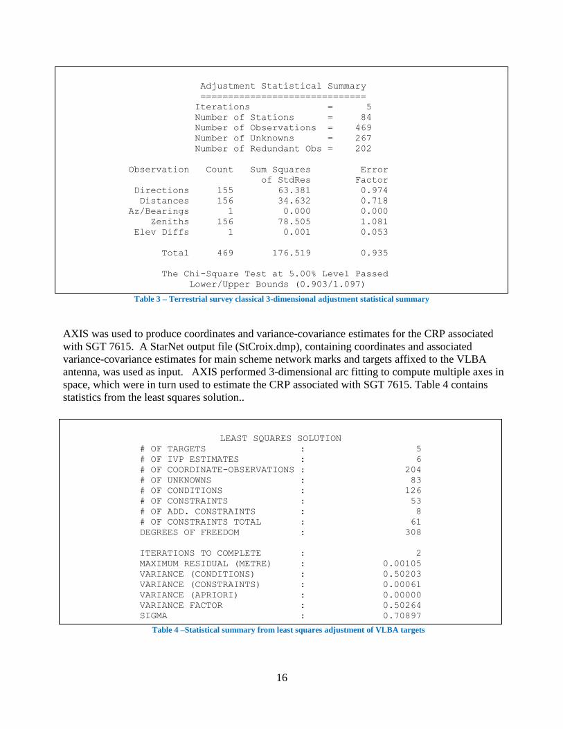
AXIS was used to produce coordinates and variance-covariance estimates for the CRP associated
with SGT 7615. A StarNet output file (StCroix.dmp), containing coordinates and associated
variance-covariance estimates for main scheme network marks and targets affixed to the VLBA
antenna, was used as input. AXIS performed 3-dimensional arc fitting to compute multiple axes in
space, which were in turn used to estimate the CRP associated with SGT 7615. Table 4 contains
statistics from the least squares solution..
Table 4 –Statistical summary from least squares adjustment of VLBA targets
Adjustment Statistical Summary
==============================
Iterations = 5
Number of Stations = 84
Number of Observations = 469
Number of Unknowns = 267
Number of Redundant Obs = 202
Observation Count Sum Squares Error
of StdRes Factor
Directions 155 63.381 0.974
Distances 156 34.632 0.718
Az/Bearings 1 0.000 0.000
Zeniths 156 78.505 1.081
Elev Diffs 1 0.001 0.053
Total 469 176.519 0.935
The Chi-Square Test at 5.00% Level Passed
Lower/Upper Bounds (0.903/1.097)
LEAST SQUARES SOLUTION
# OF TARGETS : 5
# OF IVP ESTIMATES : 6
# OF COORDINATE-OBSERVATIONS : 204
# OF UNKNOWNS : 83
# OF CONDITIONS : 126
# OF CONSTRAINTS : 53
# OF ADD. CONSTRAINTS : 8
# OF CONSTRAINTS TOTAL : 61
DEGREES OF FREEDOM : 308
ITERATIONS TO COMPLETE : 2
MAXIMUM RESIDUAL (METRE) : 0.00105
VARIANCE (CONDITIONS) : 0.50203
VARIANCE (CONSTRAINTS) : 0.00061
VARIANCE (APRIORI) : 0.00000
VARIANCE FACTOR : 0.50264
SIGMA : 0.70897
17
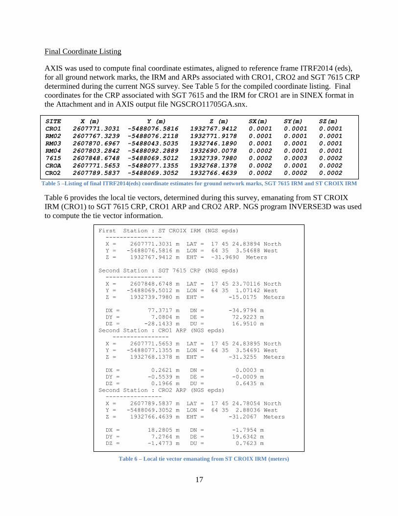
Final Coordinate Listing
AXIS was used to compute final coordinate estimates, aligned to reference frame ITRF2014 (eds),
for all ground network marks, the IRM and ARPs associated with CRO1, CRO2 and SGT 7615 CRP
determined during the current NGS survey. See Table 5 for the compiled coordinate listing. Final
coordinates for the CRP associated with SGT 7615 and the IRM for CRO1 are in SINEX format in
the Attachment and in AXIS output file NGSCRO11705GA.snx.
Table 5 –Listing of final ITRF2014(eds) coordinate estimates for ground network marks, SGT 7615 IRM and ST CROIX IRM
Table 6 provides the local tie vectors, determined during this survey, emanating from ST CROIX
IRM (CRO1) to SGT 7615 CRP, CRO1 ARP and CRO2 ARP. NGS program INVERSE3D was used
to compute the tie vector information.
Table 6 – Local tie vector emanating from ST CROIX IRM (meters)
SITE X (m) Y (m) Z (m) SX(m) SY(m) SZ(m)
CRO1 2607771.3031 -5488076.5816 1932767.9412 0.0001 0.0001 0.0001
RM02 2607767.3239 -5488076.2118 1932771.9178 0.0001 0.0001 0.0001
RM03 2607870.6967 -5488043.5035 1932746.1890 0.0001 0.0001 0.0001
RM04 2607803.2842 -5488092.2889 1932690.0078 0.0002 0.0001 0.0001
7615 2607848.6748 -5488069.5012 1932739.7980 0.0002 0.0003 0.0002
CROA 2607771.5653 -5488077.1355 1932768.1378 0.0002 0.0001 0.0002
CRO2 2607789.5837 -5488069.3052 1932766.4639 0.0002 0.0002 0.0002
First Station : ST CROIX IRM (NGS epds)
----------------
X = 2607771.3031 m LAT = 17 45 24.83894 North
Y = -5488076.5816 m LON = 64 35 3.54688 West
Z = 1932767.9412 m EHT = -31.9690 Meters
Second Station : SGT 7615 CRP (NGS epds)
----------------
X = 2607848.6748 m LAT = 17 45 23.70116 North
Y = -5488069.5012 m LON = 64 35 1.07142 West
Z = 1932739.7980 m EHT = -15.0175 Meters
DX = 77.3717 m DN = -34.9794 m
DY = 7.0804 m DE = 72.9223 m
DZ = -28.1433 m DU = 16.9510 m
Second Station : CRO1 ARP (NGS epds)
----------------
X = 2607771.5653 m LAT = 17 45 24.83895 North
Y = -5488077.1355 m LON = 64 35 3.54691 West
Z = 1932768.1378 m EHT = -31.3255 Meters
DX = 0.2621 m DN = 0.0003 m
DY = -0.5539 m DE = -0.0009 m
DZ = 0.1966 m DU = 0.6435 m
Second Station : CRO2 ARP (NGS epds)
----------------
X = 2607789.5837 m LAT = 17 45 24.78054 North
Y = -5488069.3052 m LON = 64 35 2.88036 West
Z = 1932766.4639 m EHT = -31.2067 Meters
DX = 18.2805 m DN = -1.7954 m
DY = 7.2764 m DE = 19.6342 m
DZ = -1.4773 m DU = 0.7623 m

18
6. Planning Aspects
Contact information
The primary contact for information regarding SGT 7615 is NRAO employee Eric Carlow. Eric’s
contact information is:
Eric Carlowe
National Radio Astronomy Observatory (NRAO)
Array Operations Center
P.O. Box O
1003 Lopezville Road
Socorro, NM 87801-0387
Phone: (575) 835-7000, Fax: (575) 835-7027
Recommendations:
Plan all measurements to VLBA antenna targets around weekly maintenance days to minimize impact
on the NRAO data collection mission. At the time of this survey, every Wednesday is a maintenance
day. Once each month the VLBA has two consecutive maintenance days during a single week. This
would be the optimal week to conduct the local site survey.
Shipments to/from ST. Croix are considered to be “international” and have to pass through customs.
Also, UPS does not deliver packages to the observatory. Plan to ship to/from the project at the UPS
shipping center located at the airport.
7. References
7.1. Name of person(s) responsible for observations
Kendall Fancher ([email protected])
Benjamin Erickson ([email protected])
National Geodetic Survey
15351 Office Drive
Woodford, VA 22580
Phone – (540) 376-6535
7.2. Name of person(s) responsible for analysis
Kendall Fancher ([email protected])
Benjamin Erickson ([email protected])
National Geodetic Survey
15351 Office Drive
Woodford, VA 22580
Phone – (540) 376-6531

19
7.3. Location of observation data and results archive
National Geodetic Survey
Instrumentation & Methodologies Branch
15351 Office Drive
Woodford, VA 22580
Phone – (540) 373-1243
20
Attachment: SINEX Format
%=SNX 1.00 AUS 17:202:51969 AUS 17:134:00000 17:135:00000 C 00012 2 X
+FILE/REFERENCE
DESCRIPTION Terrestrial Survey Tie
OUTPUT SSC SINEX
CONTACT ________________________________________________
SOFTWARE axis version 1.07
HARDWARE ________________________________________________
INPUT Terrestrial Survey Solution
-FILE/REFERENCE
+FILE/COMMENT
* axis software by John Dawson Geoscience Australia
-FILE/COMMENT
+SITE/ID
RMO1 A 43201M001 C ST CROIX IRM
-64 35 3.5 17 45 24.8 -32.0
7615 A 43201S001 C SGT 7615 CRP
-64 35 1.1 17 45 23.7 -15.0
CRO1 A 43201M001 C ST CROIX CRO1 ARP -64 35 3.5 17 45 24.8 -31.3
CRO2 A --------- C ST CROIX CRO2 ARP
-64 35 2.9 17 45 24.8 -31.2
-SITE/ID
+SITE/DATA
RMO1 A 1 RMO1 A 1 17:134:00000 17:135:00000 --- 17:134:43200
7615 A 1 7615 A 1 17:134:00000 17:135:00000 --- 17:134:43200
CRO1 A 1 CRO1 A 1 17:134:00000 17:135:00000 --- 17:134:43200
CRO2 A 1 CRO2 A 1 17:134:00000 17:135:00000 --- 17:134:43200
-SITE/DATA
+SOLUTION/EPOCHS
RMO1 A 1 C 17:134:00000 17:135:00000 17:134:43200
7615 A 1 C 17:134:00000 17:135:00000 17:134:43200
CRO1 A 1 C 17:134:00000 17:135:00000 17:134:43200
CRO2 A 1 C 17:134:00000 17:135:00000 17:134:43200
-SOLUTION/EPOCHS
+SOLUTION/STATISTICS
VARIANCE FACTOR 5.026395903303587e-01
SQUARE SUM OF RESIDUALS 1.548129938217505e+02
NUMBER OF OBSERVATIONS 320
NUMBER OF UNKNOWNS 12
-SOLUTION/STATISTICS
+SOLUTION/ESTIMATE
1 STAX RMO1 A 1 17:134:43200 m 2 2.60777130313314e+06 1.00000e-04
2 STAY RMO1 A 1 17:134:43200 m 2 -5.48807658159368e+06 1.00000e-04
3 STAZ RMO1 A 1 17:134:43200 m 2 1.93276794124172e+06 1.00000e-04
4 STAX 7615 A 1 17:134:43200 m 2 2.60784867481126e+06 2.91566e-04
5 STAY 7615 A 1 17:134:43200 m 2 -5.48806950117728e+06 4.67391e-04
6 STAZ 7615 A 1 17:134:43200 m 2 1.93273979798011e+06 2.47188e-04
7 STAX CRO1 A 1 17:134:43200 m 2 2.60777156526597e+06 2.27222e-04
8 STAY CRO1 A 1 17:134:43200 m 2 -5.48807713545886e+06 1.65863e-04
9 STAZ CRO1 A 1 17:134:43200 m 2 1.93276813779702e+06 2.38745e-04
10 STAX CRO2 A 1 17:134:43200 m 2 2.60778958366561e+06 2.79539e-04
11 STAY CRO2 A 1 17:134:43200 m 2 -5.48806930524212e+06 2.13649e-04
12 STAZ CRO2 A 1 17:134:43200 m 2 1.93276646390657e+06 2.73162e-04
21
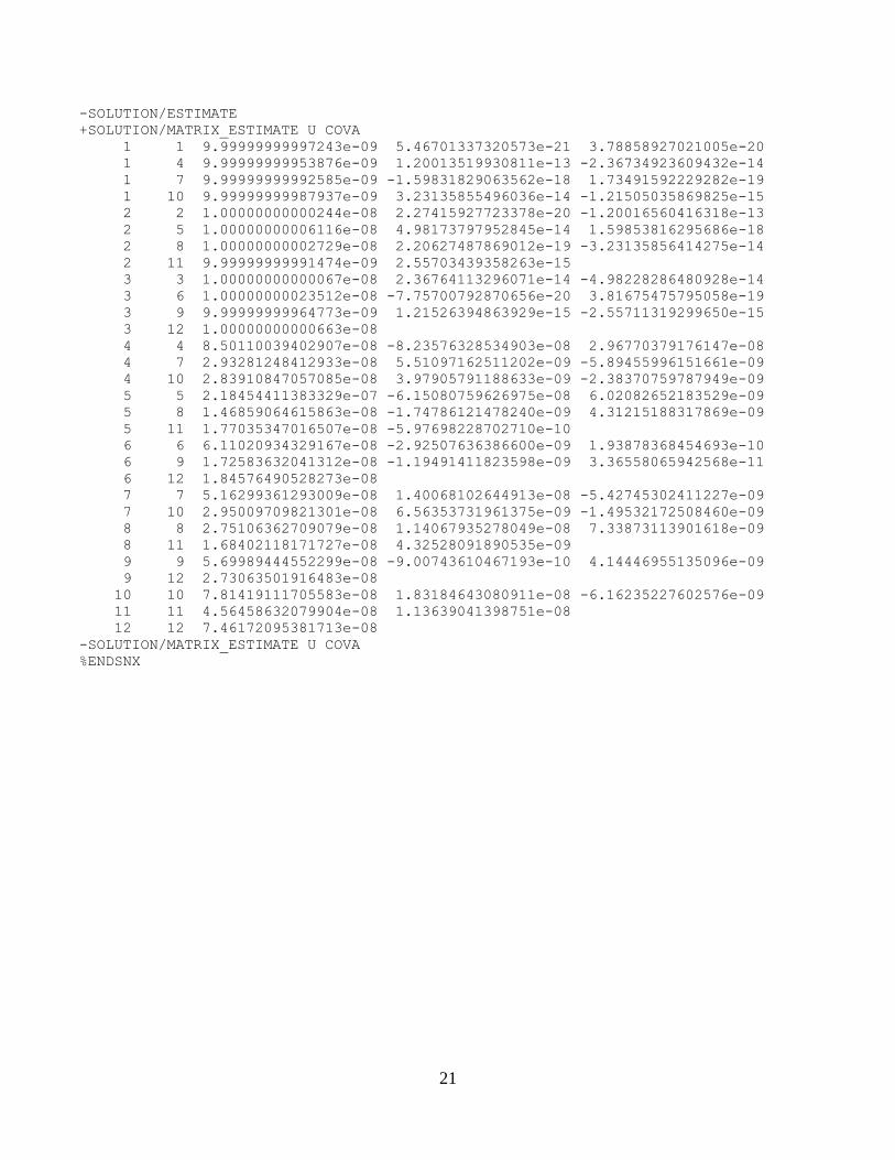
-SOLUTION/ESTIMATE
+SOLUTION/MATRIX_ESTIMATE U COVA
1 1 9.99999999997243e-09 5.46701337320573e-21 3.78858927021005e-20
1 4 9.99999999953876e-09 1.20013519930811e-13 -2.36734923609432e-14
1 7 9.99999999992585e-09 -1.59831829063562e-18 1.73491592229282e-19
1 10 9.99999999987937e-09 3.23135855496036e-14 -1.21505035869825e-15
2 2 1.00000000000244e-08 2.27415927723378e-20 -1.20016560416318e-13
2 5 1.00000000006116e-08 4.98173797952845e-14 1.59853816295686e-18
2 8 1.00000000002729e-08 2.20627487869012e-19 -3.23135856414275e-14
2 11 9.99999999991474e-09 2.55703439358263e-15
3 3 1.00000000000067e-08 2.36764113296071e-14 -4.98228286480928e-14
3 6 1.00000000023512e-08 -7.75700792870656e-20 3.81675475795058e-19
3 9 9.99999999964773e-09 1.21526394863929e-15 -2.55711319299650e-15
3 12 1.00000000000663e-08
4 4 8.50110039402907e-08 -8.23576328534903e-08 2.96770379176147e-08
4 7 2.93281248412933e-08 5.51097162511202e-09 -5.89455996151661e-09
4 10 2.83910847057085e-08 3.97905791188633e-09 -2.38370759787949e-09
5 5 2.18454411383329e-07 -6.15080759626975e-08 6.02082652183529e-09
5 8 1.46859064615863e-08 -1.74786121478240e-09 4.31215188317869e-09
5 11 1.77035347016507e-08 -5.97698228702710e-10
6 6 6.11020934329167e-08 -2.92507636386600e-09 1.93878368454693e-10
6 9 1.72583632041312e-08 -1.19491411823598e-09 3.36558065942568e-11
6 12 1.84576490528273e-08
7 7 5.16299361293009e-08 1.40068102644913e-08 -5.42745302411227e-09
7 10 2.95009709821301e-08 6.56353731961375e-09 -1.49532172508460e-09
8 8 2.75106362709079e-08 1.14067935278049e-08 7.33873113901618e-09
8 11 1.68402118171727e-08 4.32528091890535e-09
9 9 5.69989444552299e-08 -9.00743610467193e-10 4.14446955135096e-09
9 12 2.73063501916483e-08
10 10 7.81419111705583e-08 1.83184643080911e-08 -6.16235227602576e-09
11 11 4.56458632079904e-08 1.13639041398751e-08
12 12 7.46172095381713e-08
-SOLUTION/MATRIX_ESTIMATE U COVA
%ENDSNX