Embed Size (px)
Citation preview
ORDNANCE PAMPHLET No. 1303
UNITED STATES NAVY SYNCHROSDESCRIPTION AND OPERATION
15 DEC. 1944
Prepared for the Bureau of Ordnance and Bureau of Ships
by the
(eSS
RCA SERVICE COMPANY, INC.A RADIO CORPORATION OF AMERICA SUBSIDIARY
Camden, New Jersey
Edited by
K. A. SIMONS, Field Engineer
NAVY DEPARTMENT
WASHINGTON 25, D.C.
15 Dec. 1944
ORDNANCE PAMPHLET 1303UNITED STATES NAVY SYNCHROS - Description and Operation
1. The purpose of this publication is toprovide to all Naval activities necessaryinformation and operational characteristicsof Navy synchros.
2. It Is believed that it will be most usefulto the technicians on shipboard and in navalbases who maintain and repair Synchro systems.
3. This pamphlet does not supersede any existingpublication.
E. L. Cochrane G. F. HussRear Admiral, U. S. Navy Rear Admiral^U. S. NavyChief of the Bureau of Shipe Chief of the Bureau of Ordnance
U. S. NAVY SYNCHROS op 1303
CONTENTSHOW SYNCHROS WORKINTRODUCTION Page
General Description 7
Synchros Are Self-Synchronizing 10
FUNDAMENTALSHow DC Voltages Can Be Used to Position a Shah 12The Effect of Using AC Voltages 17
SYNCHRO MOTORS AND GENERATORSThe Construction of a Synchro Motor or Generator 22The Operation of Synchro Motors and Generators 26
THE OPERATION OF A COMPLETE SYNCHRO SYSTEMFundamentals 35How a Synchro Motor Follows a Generator 38How the Currents in a Synchro System Depend on Shaft Positions 41
The Torque Produced by a Synchro Motor 44Using One Generator to Drive a Number of Motors 47Factors That Affect the Accuracy of a Synchro System 49Making a Synchro Motor Turn Backwards 50
THE BEARING-MOUNTED SYNCHRO MOTOR 51
HOW A SYNCHRO DIFFERENTIAL WORKSA Mechanical Differential • 53The Construction of a Synchro Differential 55How a Synchro Differential Works 56To Reverse the Effect of a Differential's Shaft 60Rules for a Differential with Various Connections. • • • 61
A Synchro Differential May be Used Either as a Generator or a Motor 62A Differential's Rotor and Stator Leads Aren't Interchangeable 63
HOW A SYNCHRO CONTROL TRANSFORMER WORKSThe Construction of a Synchro Control Transformer 65The Operation of a Synchro Control Transformer 67Using a Differential Generator as a Control Transformer 72
HOW SYNCHRO CAPACITORS ("EXCITERS") ARE USEDThe AC Current Drawn by a Coil 73The Use of a Capacitor to Cancel the Magnetizing Current 74The Use of Capacitors With a Control Transformer 75
The Use of Capacitors With a Synchro Differential 77
General Notes Concerning Synchro Capacitors 78
Using a Capacitor to Reduce the Line Current of a Generator or Motor 79
OVERLOAD AND BLOWN FUSE INDICATORSOverload Indicators 80Blown Fuse Indicators 82
THE CHARACTERISTICS OF NAVY STANDARD SYNCHROS
THE MEANING OF SYNCHRO NAMEPLATE MARKINGSThe Mod. Number 85The Mark Number 85Designations 85
AVAILABLE TYPES OF SYNCHROS 88
TABLES OF SYNCHRO CHARACTERISTICS
Values Held by Specification 89
Values Determined by Measurements on Representative Units 90Characteristics of Navy Standard Synchro Motors 91
CONTENTS (Continued)
Page
Characteristics of Navy Standard Synchro Generators 92Characteristics of Navy Standard Synchro Differential Motors 93Characteristics of Navy Standard Synchro Differential Generators 94Characteristics of Navy Standard Synchro Control Transformers 95Characteristics of Navy Standard Synchro Capacitors 96Synchro Capacitor Boxes 97
NOTES ON NAVY STANDARD SYNCHRO UNITS
Things to Avoid 97Maximum Allowable Loading on Generators and Differential Generators 98The Current Drawn by a Differential Generator Under Operating Conditions 98The Preferred Way of Mounting a Dial or Gear on a Synchro's Shaft 99
STANDARD CONNECTIONS FOR NAVY SYNCHROSDEFINITION OF AN "INCREASING READING" 101
STANDARD WIRE DESIGNATIONS 102
TWO SPEED SYSTEMS 102STANDARD VOLTAGES 1 03STANDARD GENERATOR CONNECTIONS 104STANDARD MOTOR CONNECTIONS 104STANDARD CONNECTIONS FOR DIFFERENTIAL GENERATORS 105STANDARD CONNECTIONS FOR DIFFERENTIAL MOTORS 105STANDARD CONNECTIONS FOR CONTROL TRANSFORMERS 106STANDARD CONNECTIONS FOR SYNCHRO CAPACITORS 107STANDARD CONNECTIONS FOR SERVO AMPLIFIERS 107STANDARD CONNECTIONS FOR SERVO MOTORS 108THE STANDARD CONNECTIONS THAT APPLY TO A TYPICAL SERVO SYSTEM... 109
ZEROING SYNCHROSINTRODUCTIONThe Advantage of Using Electrical Zero as a Reference 111The Dial Reading at Electrical Zero (The Zero Reading) 111What is Meant by "Zeroing" a Synchro 111To Avoid Trouble 112
TO ZERO A SYNCHRO MOTORMethod A 112Method B 113
TO ZERO A BEARING-MOUNTED SYNCHRO MOTOR 113
TO ZERO A SYNCHRO GENERATORUsing a Standard Motor 115Using an AC Voltmeter. • 116Using Two Lamps and a Pair of Headphones 117
TO ZERO A DIFFERENTIAL MOTORMethod A 118Method B 119
TO ZERO A DIFFERENTIAL GENERATORUsing a Standard Motor and a Generator 1 20Using an AC Voltmeter 1 21
Using Two Lamps and a Pair of Headphones 1 22
TO ZERO A CONTROL TRANSFORMERUsing an AC Voltmeter 123Using Two Lamps and a Pair of Headphones 1 24
THE MAINTENANCE OF SYNCHROSREPAIRING DEFECTIVE SYNCHROS
General Rules 125
5
U. S. NAVY SYNCHROS op 1303
LUBRICATING A SYNCHRO PageTo Take fhe Rotor Out 1 26To Lubricate a Synchro 127
FINDING TROUBLE IN A SYNCHRO SYSTEMGeneral Hints 127Some Symptoms and Their Probable Causes 128Miscellaneous Symptoms 1 35To Check the Voltage Balance of a Generator or DG 1 35Trouble-Shooting with an AC Voltmeter 1 36
OSCILLATION AND SPINNING IN SYNCHRO SYSTEMSOscillations Caused by Switching 137Oscillations or Spinning Caused by a Defective Synchro or Short Circuit 1 39
INTERIOR COMMUNICATION SELF-SYNCHRONOUS TRANSMITTERGENERATORS AND INDICATOR MOTORS
GENERAL DESCRIPTIONElectrical Construction 1 41Voltage Ratings 142Direction of Rotation 142
ELECTRICAL ZERO SETTINGTo Zero an Indicator Motor 1 44To Zero a Transmitter Generator 1 44
TROUBLE SHOOTING 1 46
MAINTENANCECleaning Brushes or Slip Rings 147Oiling or Replacing a Rotor 1 47
CHARACTERISTICS OF BUREAU OF SHIPS SELF SYNCHRONOUS UNITS5 Size Units 1 481 Size Generators 1 496 Size Generators 1 50
THE INTERCHANGEABLY OF BU-SHIPS UNITSReplacing a Bu-Ships Unit with Another Bu-Ships Unit 152Replacing a Bu-Ships Unit with a Synchro. • • 152Obsolete Types 153
APPENDIXA GEOMETRICAL WAY OF SHOWING THE VOLTAGE RELATIONSHIPS IN A
SYNCHRO SYSTEM 155
THE STEP-BY-STEP SYSTEMHow a Step-by-Step Motor Works 157How a Step-by-Step System Works 1 59Standard Connections in a Step-by-Step System 160Setting Zero on a Step-by-Step Repeater 1 60
STEP-BY-STEP TO SYNCHRO CONVERTERSA Simple Converter 1 61To Zero a Converter 1 61A More Complicated Type of Converter 1 62
INDEX 163
DISTRIBUTION LIST 166
6
HOW SYNCHROS WORKINTRODUCTION
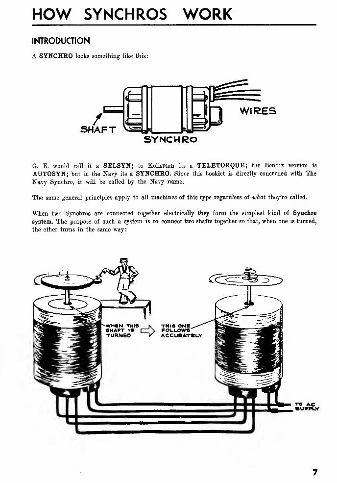
A SYNCHRO looks something like this
:
WIRES
SYNCHRO
G. E. would call it a SELSYN; to Kollsman its a TELETORQUE; the Bendix version is
AUTOSYN; but in the Navy its a SYNCHRO. Since this booklet is directly concerned with The
Navy Synchro, it will be called by the Navy name.
The same general principles apply to all machines of this type regardless of what they're called.
When two Synchros are connected together electrically they form the simplest kind of Synchro
system. The purpose of such a system is to connect two shafts together so that, when one is turned,
the other turns in the same way:
TO AC•UPPUY
U. S. NAVY SYNCHROS OP 1303
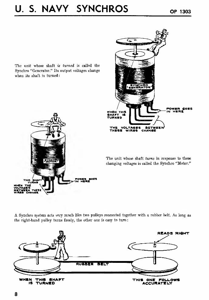
The unit whose shaft is turned is called the
Synchro "Generator." Its output voltages change
when its shaft is turned:
THISTURNS
WHEN THEVOL.TACKSBETWEEN THEStWIRES CHANOK
WHEN THISSHAFT 18TURNHD
THE VOLTASBS BETWEEN 1
THESE WIRES CHANSE
POWER 60ESIN HERE
The unit whose shaft turns in response to these
changing voltages is called the Synchro "Motor."
power soa«N HERE
A Synchro system acts very much like two pulleys connected together with a rubber belt. As long as
the right-hand pulley turns freely, the other one is easy to turn
:
READS RIGHT
WHEN THIS SHAFTIS TURNED
THIS ONE FOLLOW*ACCURATELY
8
INTRODUCTION
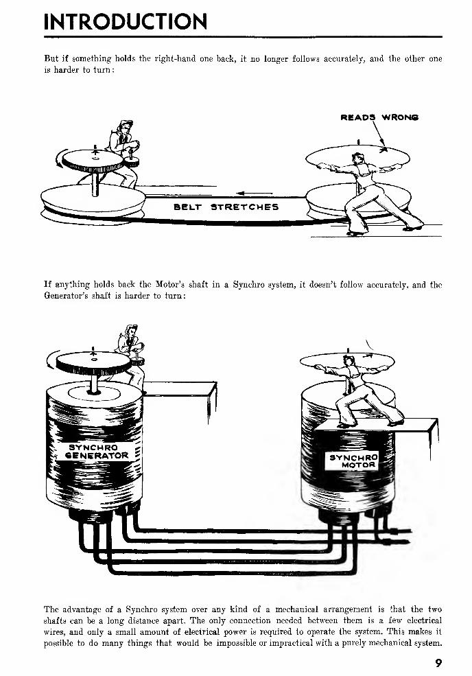
But if something holds the right-hand one back, it no longer follows accurately, and the other one
is harder to turn:
READS WRONG
If anything holds back the Motor's shaft in a Synchro system, it doesn't follow accurately, and the
Generator's shaft is harder to turn:
The advantage of a Synchro system over any kind of a mechanical arrangement is that the two
shafts can be a long distance apart. The only connection needed between them is a few electrical
wires, and only a small amount of electrical power is required to operate the system. This makes it
possible to do many things that would be impossible or impractical with a purely mechanical system.
U. S. NAVY SYNCHROS OP 1303
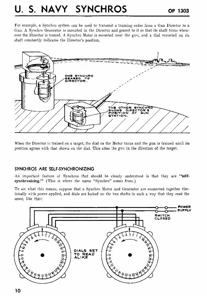
For example, a Synchro system can be used to transmit a training order from a Gun Director to a
Gun. A Synchro Generator is mounted in the Director and geared to it so that its shaft turns when-
ever the Director is turned. A Synchro Motor is mounted near the gun, and a dial mounted on its
shaft constantly indicates the Director's position.
When the Director is trained on a target, the dial on the Motor turns and the gun is trained until its
position agrees with that shown on the dial. This aims the gun in the direction of the target.
SYNCHROS ARE SELF-SYNCHRONIZING
An important feature of Synchros that should be clearly understood is that they are "self-
synchronizing." (This is where the name "Synchro" comes from.)
To see what this means, suppose that a Synchro Motor and Generator are connected together elec-
trically with power applied, and dials are locked on the two shafts in such a way that they read the
same, like this:
DIALS SETTO READALIKE
POWERSUPPLY
10
INTRODUCTION
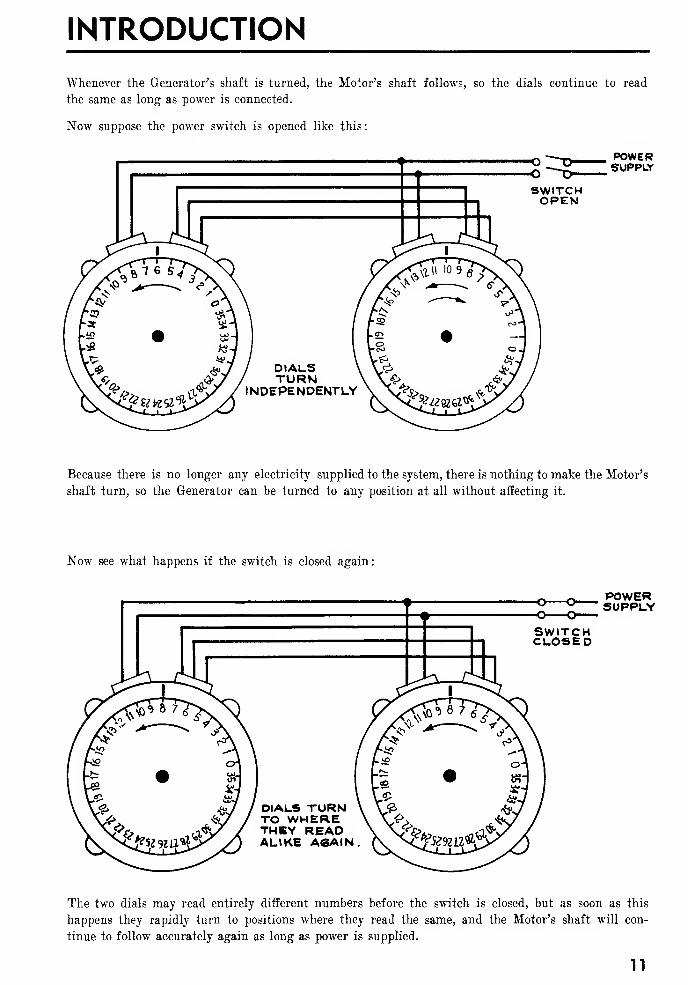
Whenever the Generator's shaft is turned, the Motor's shaft follows, so the dials continue to read
the same as long as power is connected.
Now suppose the power switch is opened like this
:
POWERSUPPLY
Because there is no longer any electricity supplied to the system, there is nothing to make the Motor's
shaft turn, so the Generator can be turned to any position at all without affecting it.
Now see what happens if the switch is closed again:
POWERSUPPLY
The two dials may read entirely different numbers before the switch is closed, but as soon as this
happens they rapidly turn to positions where they read the same, and the Motor's shaft will con-
tinue to follow accurately again as long as power is supplied.
11
U. S. NAVY SYNCHROS OP 1303
FUNDAMENTALS
To make the operation of a Synchro system easier to understand it will be approached gradually.
The following section will show how DC voltages can be used to turn a shaft to any desired position.
DC is not used in a Synchro system, but the operation of these simpler arrangements is somewhat
similar to that of a Synchro Motor, and will help to understand it.
HOW DC VOLTAGES CAN BE USED TO POSITION A SHAFT
The problem is to take a shaft and to mount it in such a way that its position can be changed by
varying an electrical voltage.
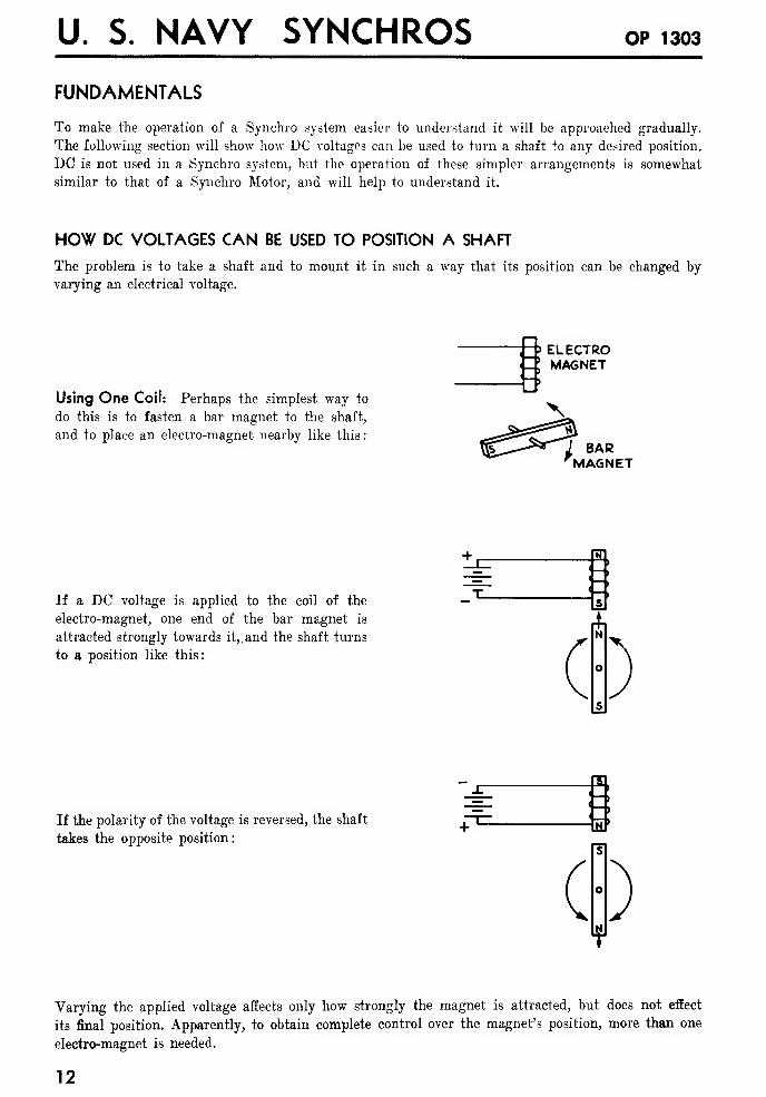
Using One Coil: Perhaps the simplest way to
do this is to fasten a bar magnet to the shaft,
and to place an electro-magnet nearby like this:
:-?:-»
t> ELECTROMAGNET
N
/ BARMAGNET
If a DC voltage is applied to the coil of the
electro-magnet, one end of the bar magnet is
attracted strongly towards it,.and the shaft turns
to a position like this:
N
If the polarity of the voltage is reversed, the shaft
takes the opposite position:
i;i
Varying the applied voltage affects only how strongly the magnet is attracted, but does not effect
its final position. Apparently, to obtain complete control over the magnet's position, more than one
electro-magnet is needed.
12
FUNDAMENTALS
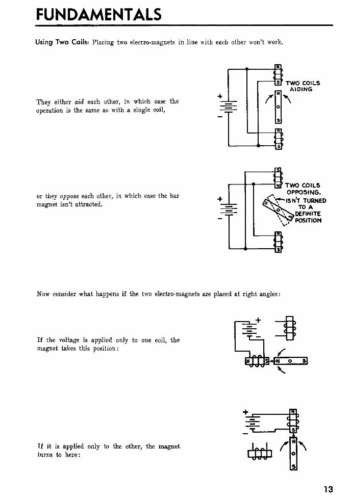
Using Two Coils: Placing two electro-magnets in line with each other won't work.
They either aid each other, in which case the
operation is the same as with a single coil,
rTWO COILSAIDING
N
s
or they oppose each other, in which case the bar
magnet isn't attracted.
M TWO COILSOPPOSING.
ifiC^- ISNT TURNED^>< TO A.DEFINITE
, POSITION
Now consider what happens if the two electro-magnets are placed at right angles
:
If the voltage is applied only to one coil, the
magnet takes this position:
\-\
V
If it is applied only to the other, the magnet
turns to here: ij&br *\
13
U. S. NAVY SYNCHROS OP 1303
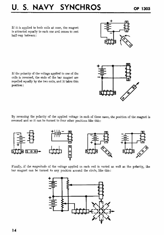
If it is applied to both coils at once, the magnet
is attracted equally to each one and comes to rest
half-way between:
1 ; J
FUNDAMENTALS
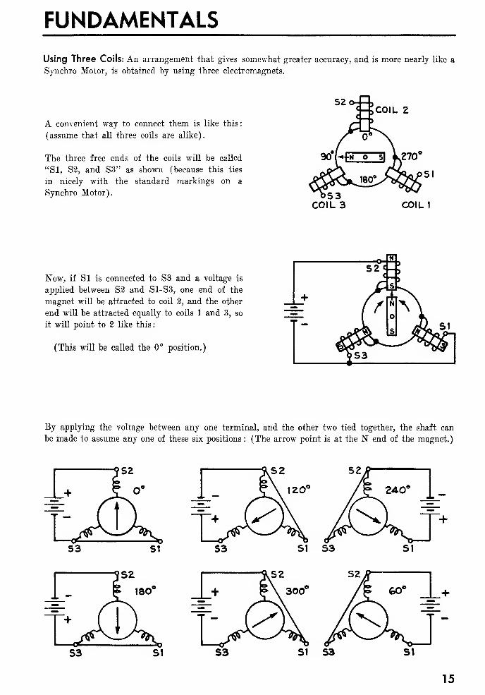
Using Three Coils: An arrangement that gives somewhat greater accuracy, and is more nearly like a
Synchro Motor, is obtained by using three electromagnets.
A convenient way to connect them is like this:
(assume that all three coils are alike).
The three free ends of the coils will be called
"SI, S2, and S3" as shown (because this ties
in nicely with the standard markings on a
Synchro Motor).
COIL 2
Now, if Si is connected to S3 and a voltage is
applied between S2 and S1-S3, one end of the
magnet will be attracted to coil 2, and the other
end will be attracted equally to coils 1 and 3, so
it will point to 2 like this:
(This will be called the 0° position.)
By applying the voltage between any one terminal, and the other two tied together, the shaft can
be made to assume any one of these six positions : (The arrow point is at the N end of the magnet.)
15
U. S. NAVY SYNCHROS OP 1303
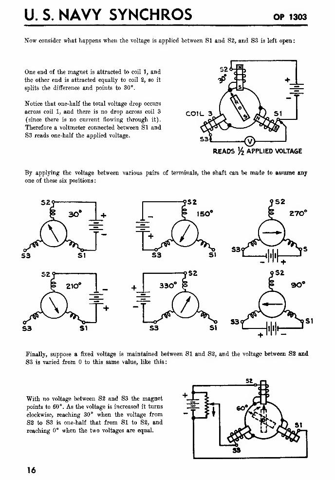
Now consider what happens when the voltage is applied between SI and S2, and S3 is left open
:
One end of the magnet is attracted to coil 1, and
the other end is attracted equally to coil 2, so it
splits the difference and points to 30°.
Notice that one-half the total voltage drop occurs
across coil 1, and there is no drop across coil 3
(since there is no current flowing through it).
Therefore a voltmeter connected between SI and
S3 reads one-half the applied voltage.
COIL 3
READS Y2 APPLIED VOLTAGE
By applying the voltage between various pairs of terminals, the shaft can be made to assume any
one of these six positions
:
Finally, suppose a fixed voltage is maintained between SI and S2, and the voltage between S2 and
S3 is varied from to this same value, like this:
SI. n
With no voltage between S2 and S3 the magnet
points to 60°. As the voltage is increased it turns
clockwise, reaching 30° when the voltage from
S3 to S3 is one-half that from SI to S2, and
reaching 0° when the two voltages are equal.
16
FUNDAMENTALS
By applying the right combination of voltages to these three coils it is possible to make the magnet,
and the shaft to which it is attached, turn to any desired position. This is quite similar to the way a
Synchro Motor works, except that, in a Synchro, AC voltages are used in place of DC. The next
section will discuss the effects that result from the use of AC voltages.
THE EFFECT OF USING AC VOLTAGES
Practically, 60 cycle AC voltages are used in a Synchro system. To understand how this affects its
operation, consider some of the characteristics of AC voltages.
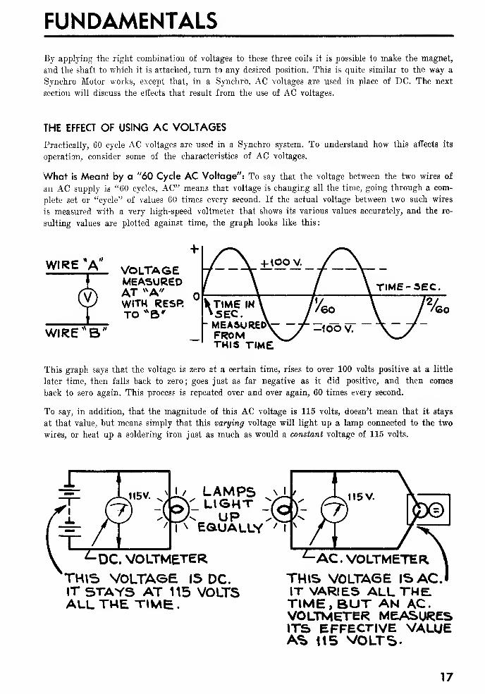
What is Meant by a "60 Cycle AC Voltage": To say that the voltage between the two wires of
an AC supply is "60 cycles, AC" means that voltage is changing all the time, going through a com-
plete set or "cycle" of values 60 times every second. If the actual voltage between two such wires
is measured with a very high-speed voltmeter that shows its various values accurately, and the re-
sulting values are plotted against time, the graph looks like this:
WIRE "A"
WIRE"B'
VOLTAGEMEASUREDAT VVA"WITH RESRTO *B' 5EC
.
h MEASURED'FROMTHIS TIME
This graph says that the voltage is zero at a certain time, rises to over 100 volts positive at a little
later time, then falls back to zero; goes just as far negative as it did positive, and then comes
back to zero again. This process is repeated over and over again, 60 times every second.
To say, in addition, that the magnitude of this AC voltage is 115 volts, doesn't mean that it stays
at that value, but means simply that this varying voltage will light up a lamp connected to the two
wires, or heat up a soldering iron just as much as would a constant voltage of 115 volts.
LAMPSLIGHT
. „ UPI\ EQUALLY
DC. VOLTMETER'THIS VOLTAGE 15 DC.IT STAYS AT 115 VOLTSALL THE TIME
.
L-AC. VOLTMETERTHIS VOLTA6E IS AC.'IT VARIES ALL THE.TIME, BUT AN AC.VOLTMETER MEASURESITS EFFECTIVE VALUEAS 115 VOLTS-
17
U. S. NAVY SYNCHROS OP 1303
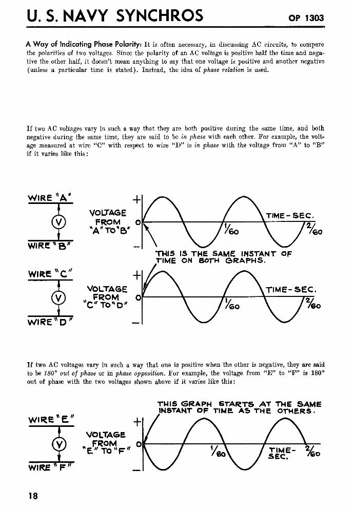
A Way of Indicating Phase Polarity: It is often necessary, in discussing AC circuits, to compare
the polarities of two voltages. Since the polarity of an AC voltage is positive half the time and nega-
tive the other half, it doesn't mean anything to say that one voltage is positive and another negative
(unless a particular time is stated). Instead, the idea of phase relation is used.
If two AC voltages vary in such a way that they are both positive during the same time, and both
negative during the same time, they are said to be in phase with each other. For example, the volt-
age measured at wire "C" with respect to wire "D" is in phase with the voltage from "A" to "B"
if it varies like this:
« a*WIRE "A
« a."WIRE * B
WIREVN
C"
WIRE W D"
-f
VOUAGEFROM O
*A"TO*B"
TIME- sec.
THI5 IS THE SAME INSTANT OFTIME ON BOTH ©RAPHS.
+VOLTAGE
„ FROM OTIME- SEC.
If two AC voltages vary in such a way that one is positive when the other is negative, they are said
to be 180° out of phase or in phase opposition. For example, the voltage from "E" to "F" is 180°
out of phase with the two voltages shown above if it varies like this
:
fi c a
THIS GRAPH STARTS AT THE SAMEINSTANT OF TIMB AS THE OTHERS.
WIRE E
VOLTAGEw FROM „ O*E"TO MF"
WIRE"F"
TIME- %n
18
FUNDAMENTALS
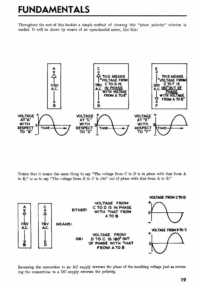
Throughout the rest of this booklet a simple method of showing this "phase polarity" relation is
needed. It will be shown by means of an open-headed arrow, like this
:
Co
A THIS MEANS"VOLTAGE FROM
78Y. C TO D IS
AC * IN PHASEi WITH VOLTAGE
FROMATOB"
oO
Eo
I THIS MEANSrVOLTAGE FROM
ETOF IS
18O°0UT_O£
EHASEWITH VOLTAGE
^ FROMATOB"oF
50V.
A.C.
1
VOLTAGE +AT "A"
WITH QRESPECTTO "B"
VOLTAGE +AT "C"WITH
RESPECT | TIMETO "D"
VOLTAGEAT W
E"WITH ol
RESPECTTO'F"
Notice that it means the same thing to say "The voltage from C to D is in phase with that from Ato B," or as to say "The voltage from D to C is 180° out of phase with that from A to B."
A
U. S. NAVY SYNCHROS OP 1303
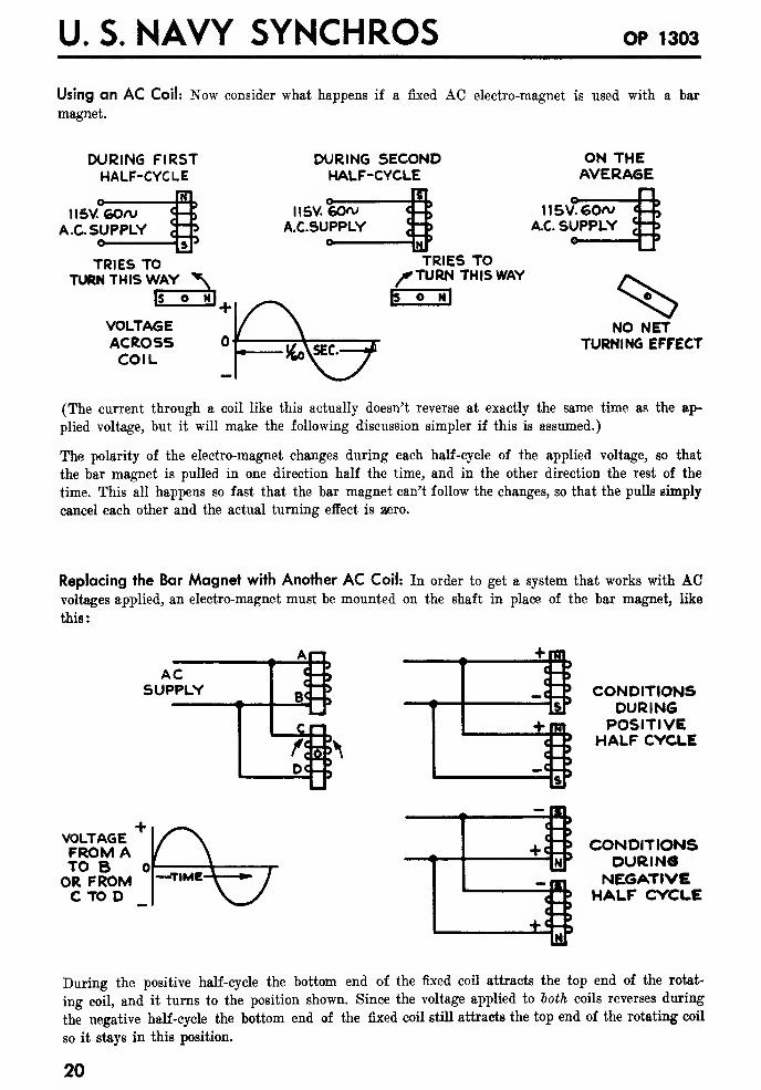
Using an AC Coil: Now consider what happens if a fixed AC electro-magnet is used with a bar
magnet.
DURING FIRSTHALF-CYCLE
„ EI115V. GOA/
A.C SUPPLYo
DURING SECONDHALF-CYCLE
. EL
ON THEAVERA6E
115V. GOVA.C.SUPPLY
o
TRIES TOTURN THIS WAY "*v
VOLTAGEACROSSCOIL
TRIES TO^rTURN THIS WAY
HE3
115V. GO~AC. SUPPLY
o
^>NO NET
TURNING EFFECT
(The current through a coil like this actually doesn't reverse at exactly the same time as the ap-
plied voltage, but it will make the following discussion simpler if this is assumed.)
The polarity of the electro-magnet changes during each half-cycle of the applied voltage, so that
the bar magnet is pulled in one direction half the time, and in the other direction the rest of the
time. This all happens so fast that the bar magnet can't follow the changes, so that the pulls simply
cancel each other and the actual turning effect is aero.
Replacing the Bar Magnet with Another AC Coil: In order to get a system that works with ACvoltages applied, an electro-magnet must be mounted on the shaft in place of the bar magnet, like
this:
ACSUPPLY
An
M£0fl*>\
VOLTAGEFROM ATO BOR FROMC TO D
FUNDAMENTALS
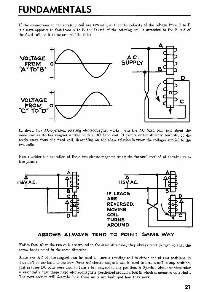
If the connections to the rotating coil are reversed, so that the polarity of the voltage from C to Dis always opposite to that from A to B, the D end of the rotating coil is attracted to the B end of
the fixed coil, so it turns around like this-:
+VOLTAGEFROM O
*Av TO"B'
A.C.SUPPLY
+VOLTAGEvFROM O
X." TO*D"
In short, this AC-operated, rotating electro-magnet works, with the AC fixed coil, just about the
same way as the bar magnet worked with a DC fixed coil. It points either directly towards, or di-
rectly away from the fixed coil, depending on the phase relation between the voltages applied to the
two coils.
Now consider the operation of these two electro-magnets using the "arrow" method of showing rela-
tive phase
:
M5VA.C.J TV
115V. AC.I
Jj->DLJ
IF LEADSAREREVERSED,MOVINGCOILTURNSAROUND
An
11=B
vjilT
ARROWS ALWAYS TEND TO POINT SAME WAY
Notice that, when the two coils are wound in the same direction, they always tend to turn so that the
arrow heads point in the same direction.
Since one AC electro-magnet can be used to turn a rotating coil to either one of two positions, it
shouldn't be too hard to see how three AC electro-magnets can be used to turn a coil to any position,
just as three DC coils were used to turn a bar magnet to any position. A Synchro Motor or Generator
is essentially just three fixed electro-magnets positioned around a fourth which is mounted on a shaft.
The next section will describe how these units are built and how they work.
21
U. S. NAVY SYNCHROS OP 1303
SYNCHRO MOTORS AND GENERATORS
THE CONSTRUCTION OF A SYNCHRO MOTOR OR GENERATOR
Before going into the detailed operation of a Synchro Motor and its use with a Synchro Generator
to form a Synchro system, the construction of these two units will be described. Except for a few
details, the construction of a Motor is the same as that of a Generator.
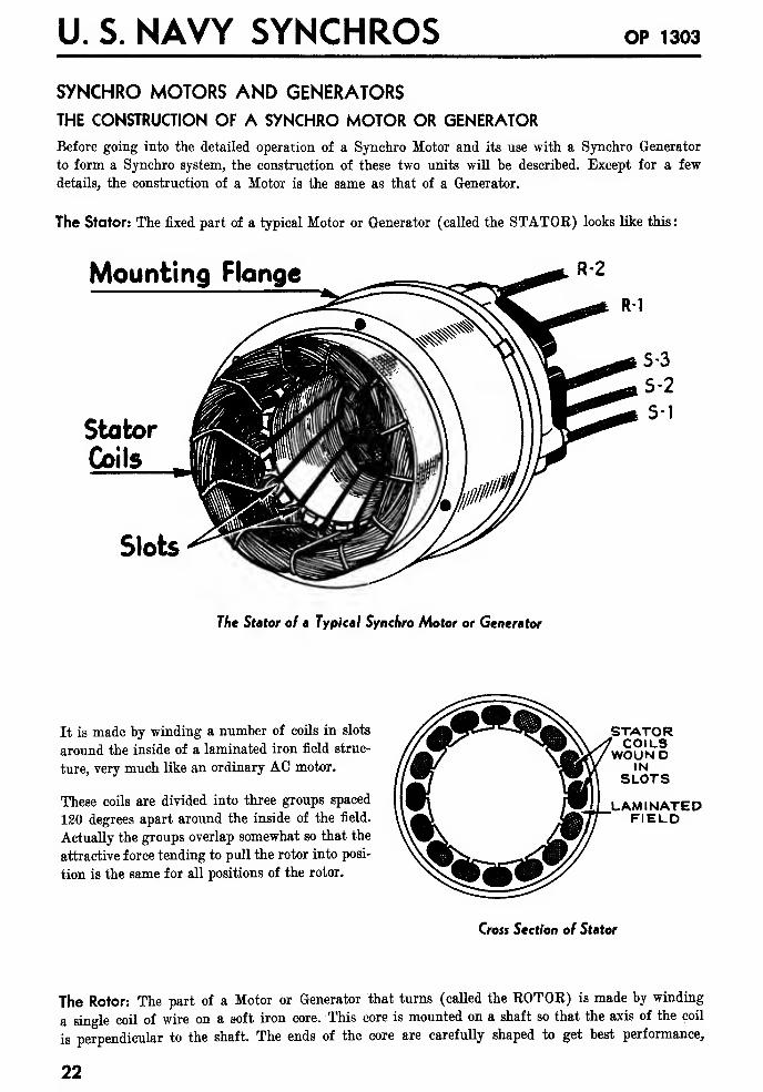
The Stator: The fixed part of a typical Motor or Generator (called the STATOE) looks like this:
Mounting Flongc
Stator
Coils
Slots
The Stator of a Typical Synchro Motor or Generator
It is made by winding a number of coils in slots
around the inside of a laminated iron field struc-
ture, very much like an ordinary AC motor.
These coils are divided into three groups spaced
120 degrees apart around the inside of the field.
Actually the groups overlap somewhat so that the
attractive force tending to pull the rotor into posi-
tion is the same for all positions of the rotor.
STATORCOILS
WOUNDIN
SLOTS
LAMINATEDFIELD
Cross Section of Stator
The Rotor: The part of a Motor or Generator that turns (called the KOTOK) is made by winding
a single coil of wire on a soft iron core. This core is mounted on a shaft so that the axis of the coil
is perpendicular to the shaft. The ends of the core are carefully shaped to get best performance,
22
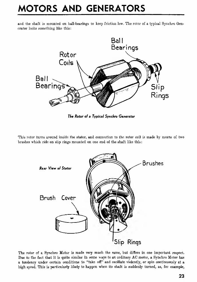
MOTORS AND GENERATORS
and the shaft is mounted on ball-bearings to keep friction low. The rotor of a typical Synchro Gen-
erator looks something like this:
Rotor
Coils
Ball
Bearing^
Ball
Bearings
The Rotor of a Typical Synchro Generator
This rotor turns around inside the stator, and connection to the rotor coil is made by means of two
brushes which ride on slip rings mounted on one end of the shaft like this
:
Rear View of Stator
Brushes
Brush Cover
Slip Rinqs
The rotor of a Synchro Motor is made very much the same, but differs in one important respect.
Due to the fact that it is quite similar in some ways to an ordinary AC motor, a Synchro Motor has
a tendency under certain conditions to "take off" and oscillate violently, or spin continuously at a
high speed. This is particularly likely to happen when its shaft is suddenly turned, as, for example,
23
U. S. NAVY SYNCHROS OP 1303
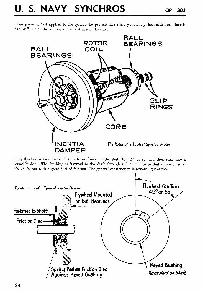
when power is first applied to the system. To prevent this a heavy metal flywheel called an "inertia
damper" is mounted on one end of the shaft, like this
:
BALLBEARINGS
ROTORCOIL
BALLBEARINGS
SLIPRINGS
INERTIADAMPER
CORE
The Rotor of a Typical Synchro Motor
This flywheel is mounted so that it turns freely on the shaft for 45° or so, and then runs into a
keyed bushing. This bushing is fastened to the shaft through a friction disc so that it can turn on
the shaft, but with a great deal of friction. The general construction is something like this
:
Construction of a Typical Inertia Damper
Flywheel Mounted
on Ball Bearings
Fastened to Shaft J*-ff
Friction Disc
Flywheel Gin Turn
45° or So
Spring Pushes Friction Disc
Against Keyed Bushing
Keyed Bushing
TurnsHardonShaft
24
MOTORS AND GENERATORS
For slow changes in the position of the shaft the flywheel simply follows along without much effect.
If the shaft tries to turn suddenly, the flywheel tends to stand still, so the friction disc acts as a
brake, slowing down the motion of the shaft. Thus the shaft never gets going fast enough to start
oscillating or spinning. If oscillation or spinning occurs it is a pretty sure sign that something is
wrong with this damper.
The Difference Between a Synchro Generator and a Synchro Motor: The difference between
these two units is in their application. Electrically a Generator of a given size is identical with a Motor
of the same size. Actually a Generator is simply a Motor with the inertia damper and certain other
refinements left off. These are needed on a Motor, but not on a Generator and would simply in-
crease its cost if added.
A Synchro Generator is always used in a position where its shaft is driven by some large unit. In
such a position it can't possibly oscillate or spin, so no damper is needed. A Synchro Motor, on the
other hand, is always used in a position where its shaft drives a small dial or operates a switch. In
such a position a damper must be used.
Never try to use a Generator in a Motor position, it will oscillate or spin.
Use a Motor in a Generator position only in an emergency when no Generator is available.
A Motor is unnecessarily expensive for such applications, and its use represents a waste of material.
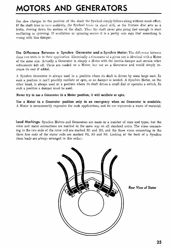
Lead Markings: Synchro Motors and Generators are made in a number of sizes and types, but the
rotor and stator connections are marked in the same way on all standard units. The wires connect-
ing to the two ends of the rotor coil are marked El and K2, and the three wires connecting to the
three free ends of the stator coils are marked SI, S2 and S3. Looking at the back of a Synchro
these leads are always arranged in this order:
Rear View of Stator
25
U. S. NAVY SYNCHROS OP 1303
THE OPERATION OF SYNCHRO MOTORS AND GENERATORS
Before taking up the operation of a complete Synchro system, in which two Synchros are connected
together, the operation of a unit by itself will be described.
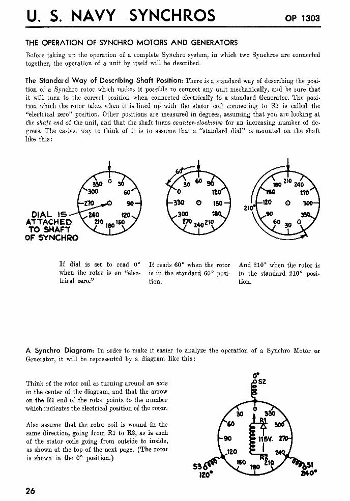
The Standard Way of Describing Shaft Position: There is a standard way of describing the posi-
tion of a Synchro rotor which makes it possible to connect any unit mechanically, and be sure that
it will turn to the correct position when connected electrically to a standard Generator. The posi-
tion which the rotor takes when it is lined up with the stator coil connecting to S2 is called the
"electrical zero" position. Other positions are measured in degrees, assuming that you are looking at
the shaft end of the unit, and that the shaft turns counter-clockwise for an increasing number of de-
grees. The easiest way to think of it is to assume that a "standard dial" is mounted on the shaft
like this:
DIAL ISATTACHEDTO SHAFTOF SYNCHRO
If dial is set to read 0°
when the rotor is on "elec-
trical zero."
It reads 60° when the rotor
is in the standard 60° posi-
tion.
And 210° when the rotor is
in the standard 210° posi-
tion.
A Synchro Diagram: In order to make it easier to analyze the operation of a Synchro Motor or
Generator, it will be represented by a diagram like this
:
Think of the rotor coil as turning around an axis
in the center of the diagram, and that the arrow
on the El end of the rotor points to the number
which indicates the electrical position of the rotor.
Also assume that the rotor coil is wound in the
same direction, going from El to E2, as is each
of the stator coils going from outside to inside,
as shown at the top of the next page. (The rotor
is shown in the 0° position.)
26
MOTORS AND GENERATORS
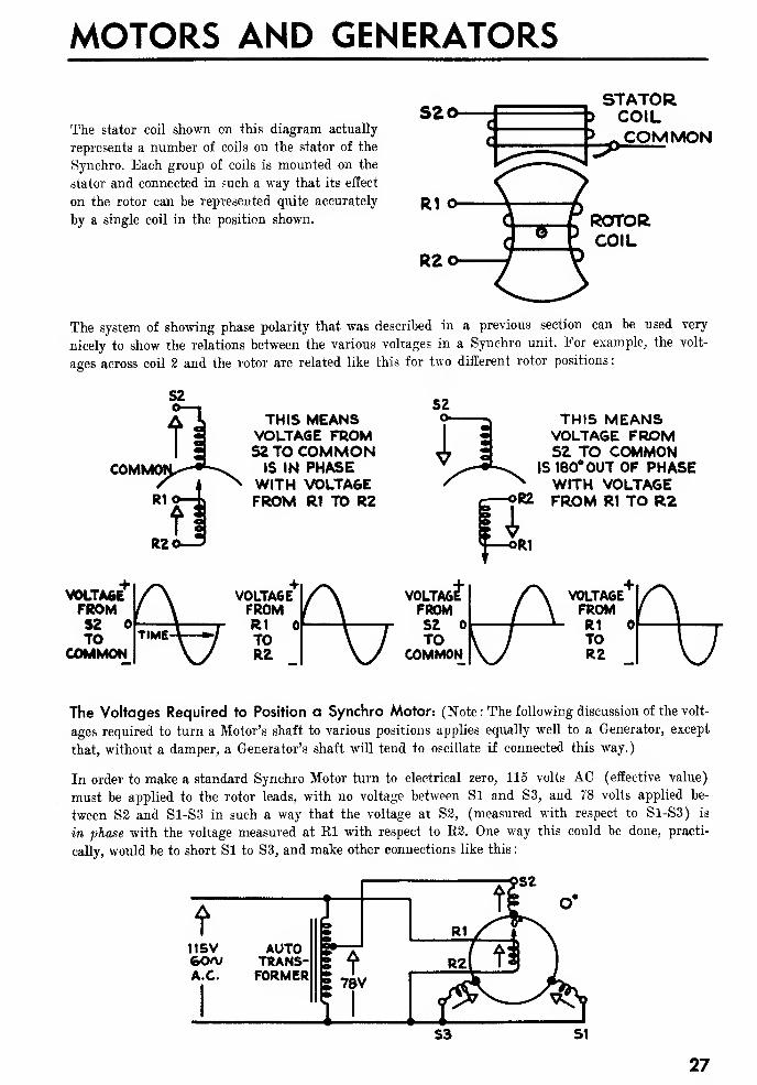
The stator coil shown on this diagram actually
represents a number of coils on the stator of the
Synchro. Each group of coils is mounted on the
stator and connected in such a way that its effect
on the rotor can be represented quite accurately
by a single coil in the position shown.
S20STATORCOIL
> COMMON
R1 O
R2o
ROTORCOIL
The system of showing phase polarity that was described in a previous section can be used very
nicely to show the relations between the various voltages in a Synchro unit. For example, the volt-
ages across coil 2 and the rotor are related like this for two different rotor positions
:
COM
THIS MEANSVOLTAGE FROMS2 TO COMMON
IS IN PHASEWITH VOLTAGEFROM R1 TO R2
S2
PkTHIS MEANSVOLTAGE FROMS2 TO COMMON
IS 180° OUT OF PHASEWITH VOLTAGE
RZ FROM R1 TO R2
VOLTAGEFROMS2TO
COMMON
The Voltages Required to Position a Synchro Motor: (Note: The following discussion of the volt-
ages required to turn a Motor's shaft to various positions applies equally well to a Generator, except
that, without a damper, a Generator's shaft will tend to oscillate if connected this way.)
In order to make a standard Synchro Motor turn to electrical zero, 115 volts AC (effective value)
must be applied to the rotor leads, with no voltage between SI and S3, and 78 volts applied be-
tween S2 and S1-S3 in such a way that the voltage at S3, (measured with respect to S1-S3) is
in phase with the voltage measured at El with respect to R2. One way this could be done, practi-
cally, would be to short Si to S3, and make other connections like this
:
27
U. S. NAVY SYNCHROS OP 1303
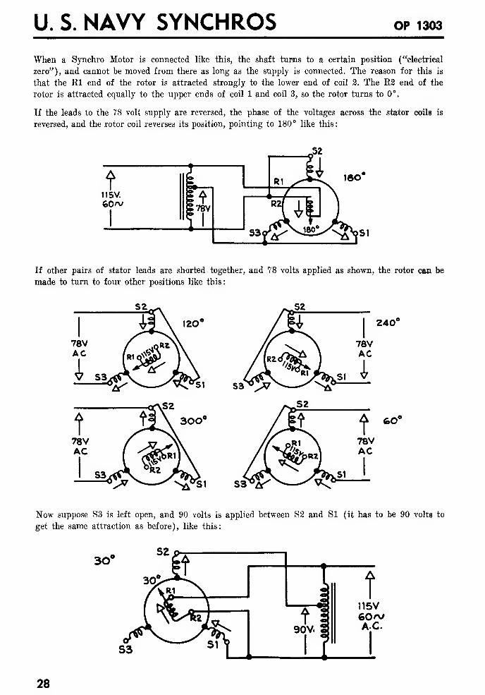
When a Synchro Motor is connected like this, the shaft turns to a certain position ("electrical
zero"), and cannot be moved from there as long as the supply is connected. The reason for this is
that the Rl end of the rotor is attracted strongly to the lower end of coil 2. The E2 end of the
rotor is attracted equally to the upper ends of coil 1 and coil 3, so the rotor turns to 0°.
If the leads to the 78 volt supply are reversed, the phase of the voltages across the stator coils is
reversed, and the rotor coil reverses its position, pointing to 180° like this:
If other pairs of stator leads are shorted together, and 78 volts applied as shown, the rotor can be
made to turn to four other positions like this:
si sa^v?
v^SI S3"°A"'
Now suppose S3 is left open, and 90 volts is applied between S3 and Si (it has to be 90 volts to
get the same attraction as before), like this:
3O
28
MOTORS AND GENERATORS
The El end of the rotor is attracted to coil 2, and the E2 end is attracted equally to coil 1, so it
takes a position half-way between, and points to 30°. Since S3 is open, the voltage between S3 and
either SI or S2 rs 45 volts.
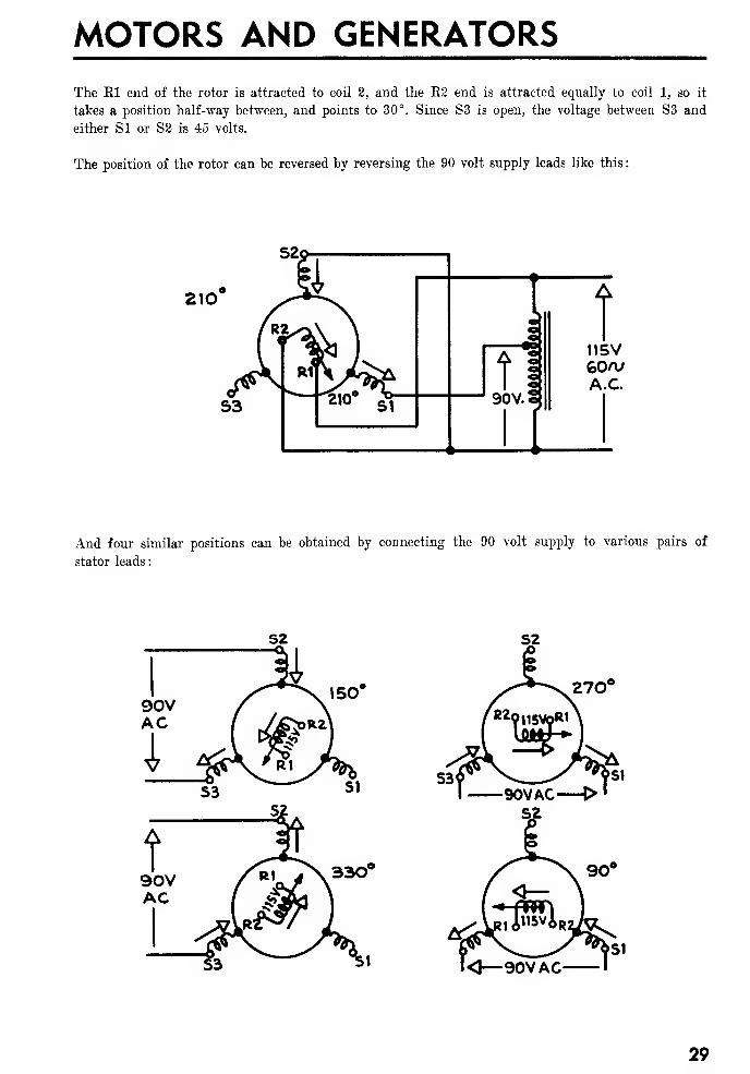
The position of the rotor can be reversed by reversing the 90 volt supply leads like this
:
210
And four similar positions can be obtained by connecting the 90 volt supply to various pairs of
stator leads:
29
U. S. NAVY SYNCHROS OP 1303
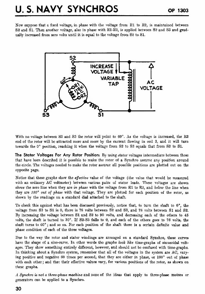
Now suppose that a fixed voltage, in phase with the voltage from El to R2, is maintained between
S2 and SI. Then another voltage, also in phase with R1-R2, is applied between S2 and S3 and grad-
ually increased from zero volts until it is equal to the voltage from S2 to Si.
ACVOLTAGE
With no voltage between S2 and S3 the rotor will point to 60°. As the voltage is increased, the R2end of the rotor will be attracted more and more by the current flowing in coil 3, and it will turn
towards the 0° position, reaching it when the voltage from S2 to S3 equals that from S2 to Si.
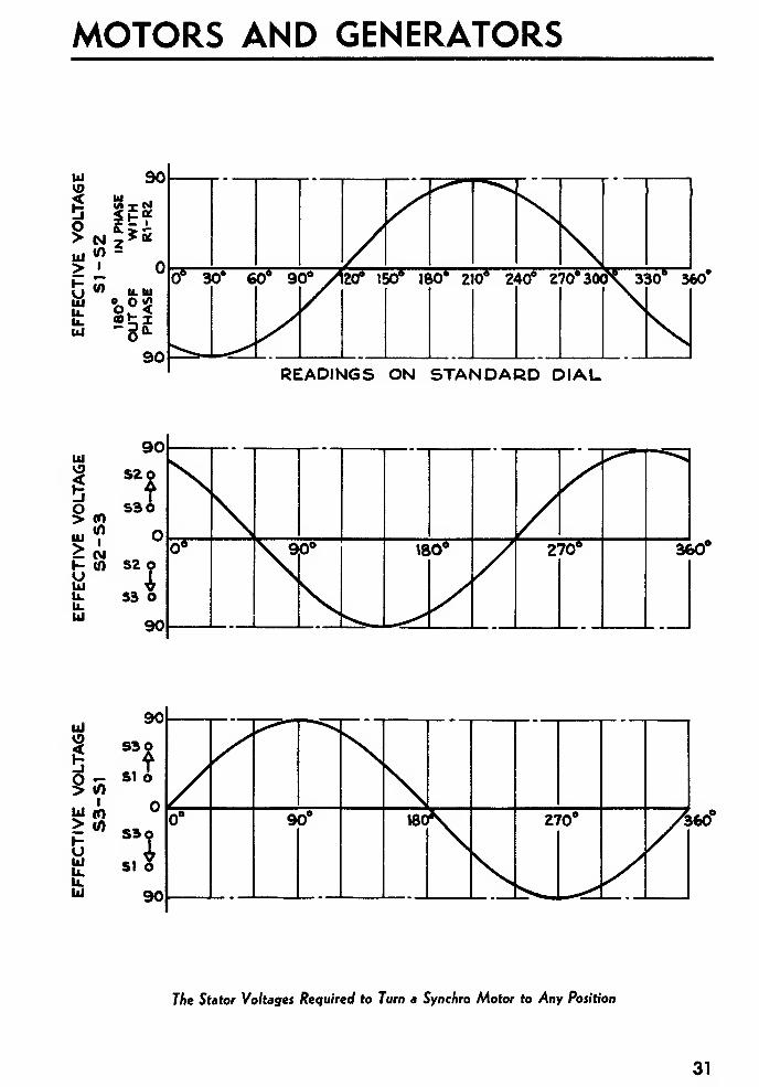
The Stator Voltages For Any Rotor Position: By using stator voltages intermediate between those
that have been described it is possible to make the rotor of a Synchro assume any position around
the circle. The voltages needed to make the rotor assume all possible positions are plotted out on the
opposite page.
Notice that these graphs show the effective value of the voltage (the value that would be measured
with an ordinary AC voltmeter) between various pairs of stator leads. These voltages are shown
above the zero line when they are in phase with the voltage from Rl to R2, and below the line whenthey are 180° out of phase with that voltage. They are plotted for each position of the rotor, as
shown by the readings on a standard dial attached to the shaft.
To check this against what has been discussed previously, notice that, to turn the shaft to 0°, the
voltage from S3 to SI is 0, there is 78 volts between S2 and S3, and 78 volts between Si and S2.
By increasing the voltage between SI and S2 to 90 volts, and decreasing each of the others to 45
volts, the shaft is turned to 30°. If S2-S3 falls to 0, and each of the others goes to 78 volts, the
shaft turns to 60° ; and so on. For each position of the shaft there is a certain definite value and
phase condition of each of the three voltages.
Due to the way the rotor and stator windings are arranged on a standard Synchro, these curves
have the shape of a sine-curve. In other words the graphs look like time-graphs of sinusoidal volt-
ages. They show something entirely different, however, and should not be confused with time-graphs.
In thinking about a Synchro system, remember that all of the voltages in the system are AC, vary-
ing positive and negative 60 times per second,- that they are either in phase, or 180° out of phase
with each other ; and that their effective values vary, for various positions of the rotor, as shown on
these graphs.
A Synchro is not a three-phase machine and none of the ideas that apply to three-phase motors or
generators can be applied to a Synchro.
30
MOTORS AND GENERATORS
330*""360#
READINGS ON STANDARD DIAL
ui
3o>
>I-
fci
u.u.UJ
CO0)I
CM(A
360"
360
The Stator Voltages Required to Turn a Synchro Motor to Any Position
31
U. S. NAVY SYNCHROS OP 1303
The Voltages Induced in the Stator Coils of a Synchro Motor or Generator: TJp to this point
only one feature of the operation of a Synchro has been discussed: How its shaft can be turned to
any desired position by changing the voltages applied to its windings. An effect that has not been
mentioned before, the voltages induced in the stator coils, plays a very important part in the opera-
tion of a Synchro system.
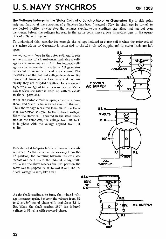
To understand this, consider for example the voltage induced in stator coil 2 when the rotor coil of
a Synchro Motor or Generator is connected to the 115 volt AC supply, and its stator leads are left
open:
An AC current flows in the rotor coil, and it acts
as the primary of a transformer, inducing a volt-
age in the secondary (coil 2). This induced volt-
age can be represented by a little AC generator
connected in series with coil 2 as shown. Themagnitude of the induced voltage depends on the
number of turns in the two coils, and on howclosely they are coupled together. In a standard
Synchro a voltage of 52 volts is induced in stator
coil 2 when the rotor is lined up with it (shaft
in the 0° position).
When the stator circuit is open, no current flows
there, and there is no internal drop in the coil.
Thus the voltage measured from S2 to the Com-mon connection is equal to the induced voltage.
Since the stator coil is wound in the same direc-
tion as the rotor coil, the voltage from S2 to Cis in phase with the voltage applied from Elto E2.
MOTORS AND GENERATORS
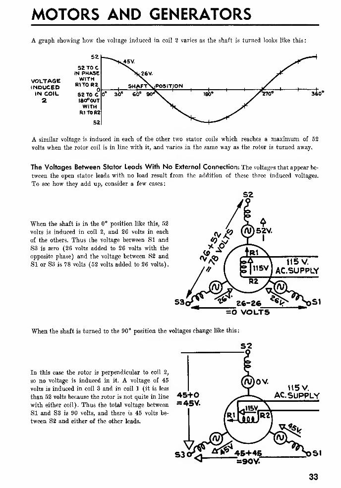
A graph showing how the voltage induced in coil 2 varies as the shaft is turned looks like this:
VOLTAGEINDUCEDIN COIL2
52
S2T0CIN PHASEWITHR1T0R2
S2TOC180°OUTWITH
R1 TO R2
52
360°
A similar voltage is induced in each of the other two stator coils which reaches a maximum of 52
volts when the rotor coil is in line with it, and varies in the same way as the rotor is turned away.
The Voltages Between Stator Leads With No External Connection: The voltages that appear be-
tween the open stator leads with no load result from the addition of these three induced voltages.
To see how they add up, consider a few cases:
When the shaft is in the 0° position like this, 52
volts is induced in coil 2, and 26 volts in each
of the others. Thus the voltage between SI and
S3 is zero (26 volts added to 26 volts with the
opposite phase) and the voltage between S2 and
SI or S3 is 78 volts (52 volts added to 26 volts).
=0 VOLTS
When the shaft is turned to the 90° position the voltages change like this
:
In this case the rotor is perpendicular to coil 2,
so no voltage is induced in it. A voltage of 45
volts is induced in coil 3 and in coil 1 (it is less
than 52 volts because the rotor is not quite in line
with either coil). Thus the total voltage between
SI and S3 is 90 volts, and there is 45 volts be-
tween S2 and either of the other leads.
S2
H5V.AC.SUPPLY
SI=90V.
33
U. S. NAVY SYNCHROS OP 1303
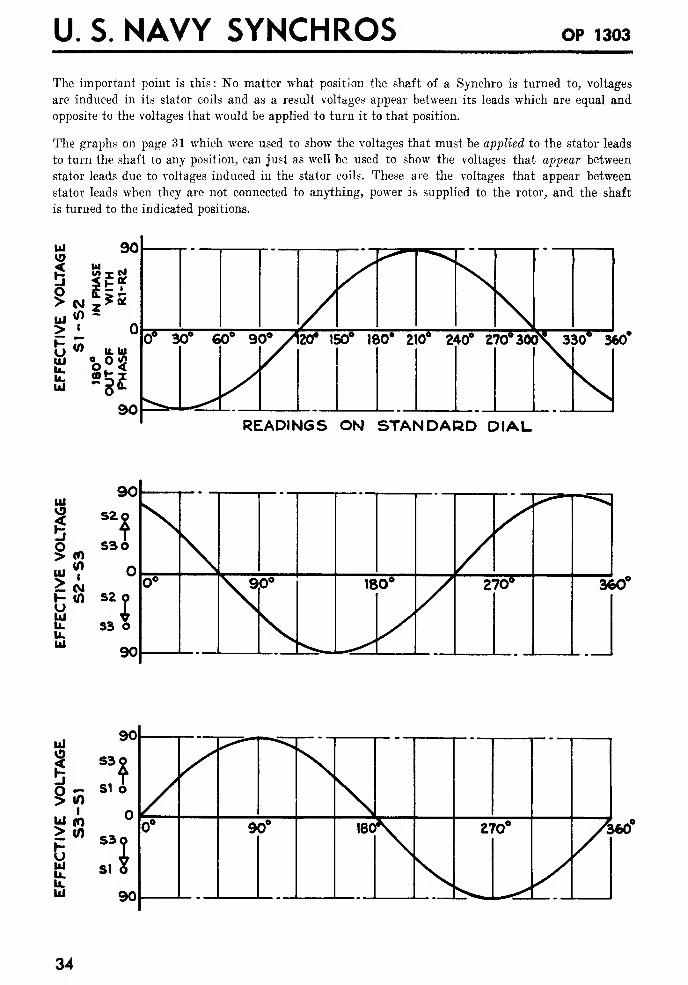
The important point is this: No matter what position the shaft of a Synchro is turned to, voltages
are induced in its stator coils and as a result voltages appear between its leads which are equal and
opposite to the voltages that would be applied to turn it to that position.
The graphs on page 31 which were used to show the voltages that must be applied to the stator leads
to turn the shaft to any position, can just as well be used to show the voltages that appear between
stator leads due to voltages induced in the stator coils. These are the voltages that appear between
stator leads when they are not connected to anything, power is supplied to the rotor, and the shaft
is turned to the indicated positions.
330 360
READINGS ON STANDARD DIAL
ui
IO>
>I-
fciu.U.UI
90
(0I
CM
S2o
S30
S2
IS3 O
90

A COMPLETE SYSTEM
THE OPERATION OF A COMPLETE SYNCHRO SYSTEM
FUNDAMENTALS
Electrically a Synchro Motor or Generator is a Transformer: From what has just been discussed
it should be fairly evident that a Synchro is, from an electrical standpoint, simply a single-phase
transformer with variable coupling between its one primary (the rotor winding) and each of its three
secondaries (the stator windings). To understand what happens when two Synchros are connected
together, it will help to discuss the action of a simple two-winding transformer.
The Operation of a Simple Transformer: When two coils are wound together on an iron
core, and one of them is connected to an AC supply, a voltage can be measured between the ends of
the other coil. If the coils have the right number of turns, the output voltage can be made equal to
100 volts, with 115 volts applied like this:
115 V. AC.SUPPLY
©<£tx READS100 VOLTS
When considering the current that flows in the secondary circuit with various loads, it simplifies
things to replace the transformer with a constant-voltage AC generator in series with an impedance
like this:
"THIS TRANSFORMER ISELECTRICALLY EQUIVALENT TO
WW100 VOLT*
(INDUCED ('V)
VOLTAGE)
10 OHMS(INTERNAL-IMPEDANCE)
OA
-OBThe AC generator represents the voltage induced in the secondary of the transformer. Its voltage is
constant (100 volts in this case) regardless of the current that flows in the secondary circuit. It de-
pends only on the voltage applied to the primary, the turns-ratio, and the coupling between the two
coils.
The series impedance (10 ohms in this case) represents the internal impedance of the transformer.
It takes care of the fact that, when current flows in the secondary circuit, the output voltage de-
creases. Its value is determined by the size of the wire used to build the transformer, the size of the
core, and the general construction of the transformer. It is related directly to the size of the trans-
former. A large transformer for a eertain job has a lower internal impedance than a small trans-
former.
If the right values of induced voltage and impedance are selected, this circuit gives the same output,
under any conditions, as does the actual transformer.
Consider what happens, for example, when a load is connected across the secondary of this trans-
former (to keep it simple, assume that the load impedance adds directly to the internal impedance) :
35
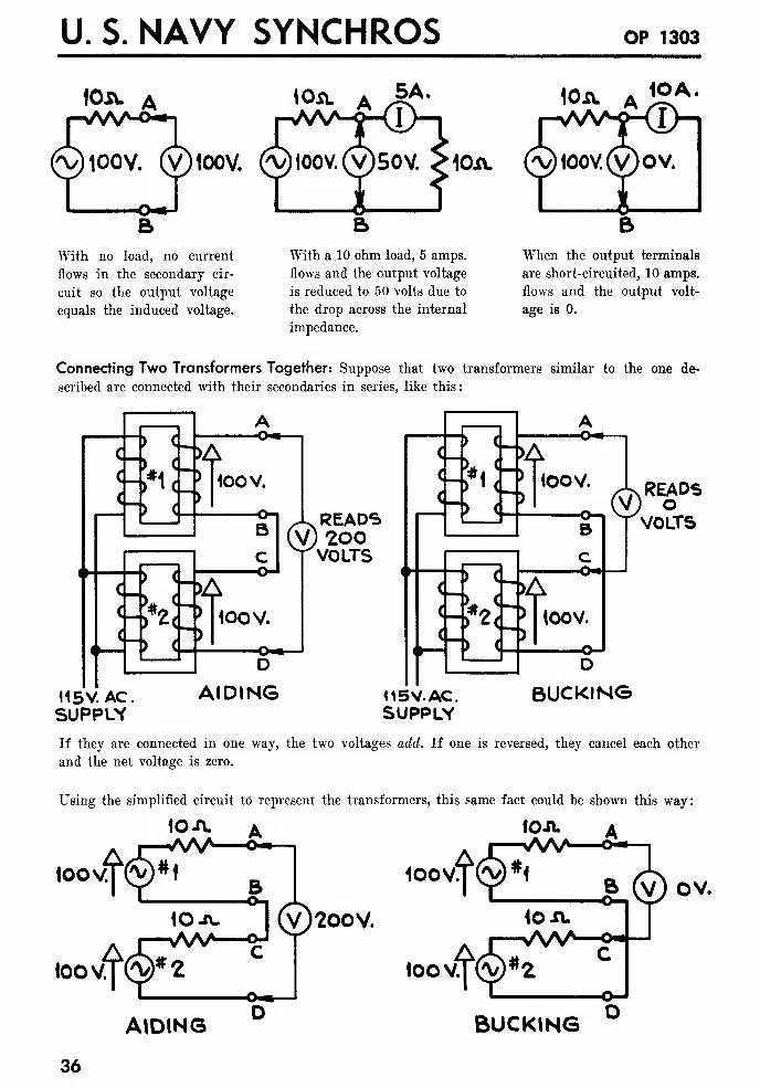
U. S. NAVY SYNCHROS OP 1303
iOSL A
(V)100V. (v)ioov.
With no load, no current
flows in the secondary cir-
cuit so the output voltage
equals the induced voltage.
\Osl A 5A- lOxv. A j2vA '
10i\.
With a.10 ohm load, 5 amps,
flows and the output voltage
is reduced to 50 volts due to
the drop across the internal
impedance.
When the output terminals
are short-circuited, 10 amps.
flows and the output volt-
age is 0.
Connecting Two Transformers Together: Suppose that two transformers similar to the one de-
scribed are connected with their secondaries in series, like this:
c- *i ohS-rol
100 V.
,J->
Rl ^ READSBI (V) 2O0
VOLTS
<->*2<_ > tooV.
115V.AC.SUPPUV
D
AIDING
f~)Jjf»<JJ«OCW-
' Ha-""
J:hS 100V.
<&READSO
VOLTS
115 V. AC.SUPPLY
D
BUCKING
If they are connected in one way, the two voltages add. If one is reversed, they cancel each other
and the net voltage is zero.
Using the simplified circuit td represent the transformers, this same fact could be shown this way:
io-n. a fo-n- a
B100V
tO-A-
toovrm^fc
©200V.
loo v.
AIDING
OV.
BUCKING
36
A COMPLETE SYSTEM
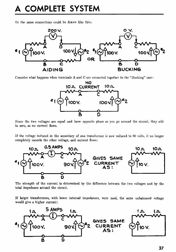
Or the same connections could be drawn like this:
2oov. O V.
B cAIDING
B DBUCKING
Consider what happens when terminals A and C are connected together in the "Bucking" case
:
NO10A, CURRENT lO-ft.
loovf©**
Since the two voltages are equal and have opposite phase as you go around the circuit, they add
to zero, so no current flows.
If the voltage induced in the secondary of one transformer is now reduced to &0 volts, it no longer
completely cancels the other voltage, and current flows:
10*. °-5AMPS lOA. 10 A. 10A.
GIVES SAMEZ CURRENT
AS:
The strength of the current is determined by the difference between the two voltages and by the
total impedance around the circuit.
If larger transformers, with lower internal impedances, were used, the same unbalanced voltage
would give a higher current:
1A.5A^PS UL
GIVES SAME2 CURRENT
AS:
37
U. S. NAVY SYNCHROS OP 1303
HOW A SYNCHRO MOTOR FOLLOWS A GENERATOR
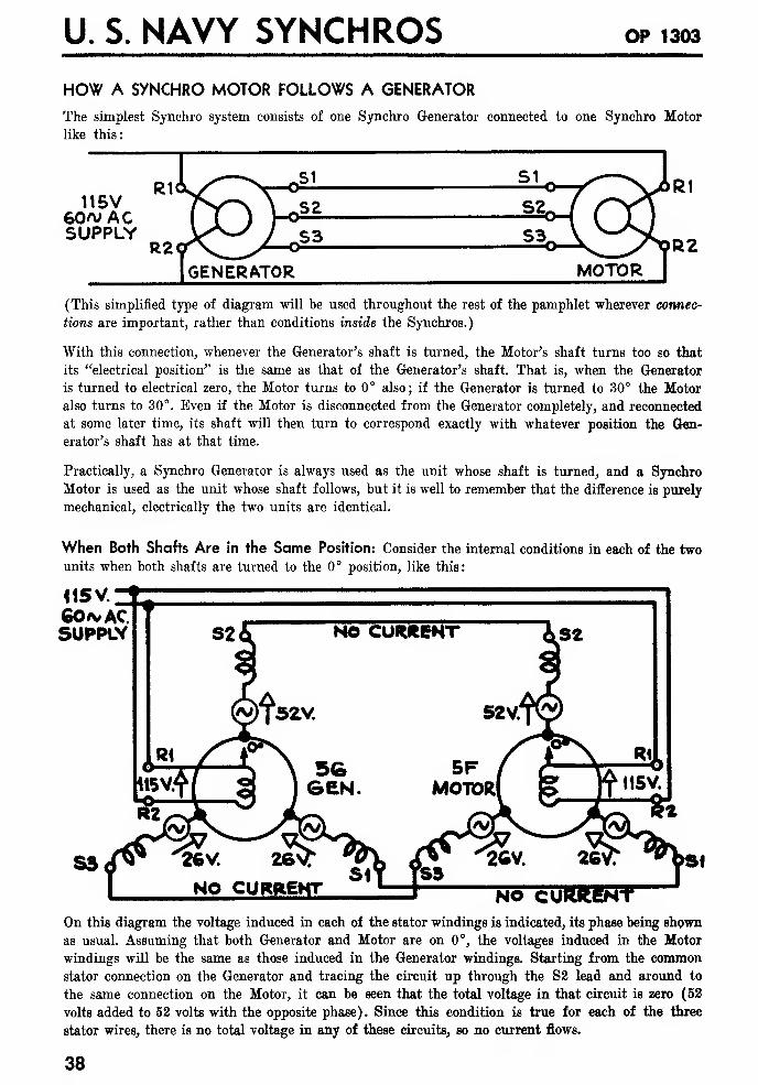
The simplest Synchro system consists of one Synchro Generator connected to one Synchro Motor
like this:
115V60/v ACSUPPLY
GENERATOR MOTOR
(This simplified type of diagram will be used throughout the rest of the pamphlet wherever connec-
tions are important, rather than conditions inside the Synchros.)
With this connection, whenever the Generator's shaft is turned, the Motor's shaft turns too so that
its "electrical position" is the same as that of the Generator's shaft. That is, when the Generator
is turned to electrical zero, the Motor turns to 0° also; if the Generator is turned to 30° the Motor
also turns to 30°. Even if the Motor is disconnected from the Generator completely, and reconnected
at some later time, its shaft will then turn to correspond exactly with whatever position the Gen-
erator's shaft has at that time.
Practically, a Synchro Generator is always used as the unit whose shaft is turned, and a Synchro
Motor is used as the unit whose shaft follows, but it is well to remember that the difference is purely
mechanical, electrically the two units are identical.
When Both Shafts Are in the Same Position: Consider the internal conditions in each of the two
units when both shafts are turned to the 0° position, like this:
<15v.
GO*ACSUPPLY
On this diagram the voltage induced in each of the stator windings is indicated, its phase being shown
as usual. Assuming that both Generator and Motor are on 0°, the voltages induced in the Motor
windings will be the same as those induced in the Generator windings. Starting from the common
stator connection on the Generator and tracing the circuit up through the S2 lead and around to
the same connection on the Motor, it can be seen that the total voltage in that circuit is zero (52
volts added to 52 volts with the opposite phase). Since this condition is true for each of the three
stator wires, there is no total voltage in any of these circuits, so no current flows.
38

A COMPLETE SYSTEM
When the Shafts Are in Different Positions: Now consider what happens when the shaft of the
Generator is turned to 30° while the Motor's shaft is held on 0°
:
115V60rv ACSUPPLY
0.75AMR -*--*-o.55AM P.
In this case none of the voltages are balanced, and currents flow in all three stator leads. The cur-
rents are strongest in the circuits where the voltage unbalance is greatest. The effect of these cur-
rents flowing in the stator coils of the Motor is to produce a strong attractive force trying to turn
the Motor's shaft toward the same position as the Generator. So, if the Motor's shaft is free to turn
(as it usually is) it turns to 30°.
The currents in the Generator's stator also cause a pull on the Generator's shaft trying to turn it
back toward the Motor's position. Since the Generator's shaft is usually being turned by something,
this pull shows up as a load on the thing that is turning it.
The turning effect of these currents can perhaps be understood better by considering a "snapshot"
showing conditions inside the two Synchros at a particular instant in the cycle of these AC currents
:
115 V.
SUPPLY
By considering the magnetic polarities it can be seen how the same currents that pull the Gen-
erator's rotor toward 0°, pull the Motor's toward 30°.
39
U. S. NAVY SYNCHROS OP 1303
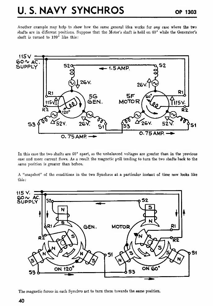
Another example may help to show how the same general idea works for any ease where the two
shafts are in different positions. Suppose that the Motor's shaft is held on 60° while the Generator's
shaft is turned to 120° like this:
11SV _6C\/ AC.SUPPLY
O. 75 AMR0.75 AMP.
In this case the two shafts are 60° apart, so the unbalanced voltages are greater than in the previous
case and more current flows. As a result the magnetic pull tending to turn the two shafts back to the
same position is greater than before.
A "snapshot" of the conditions in the two Synchros at a particular instant of time now looks like
this:
115 V.GO/v ACSUPPLY
The magnetic forces in each Synchro act to turn them towards the same position.
40
A COMPLETE SYSTEM
HOW THE CURRENTS IN A SYNCHRO SYSTEM DEPEND ON SHAFT POSITIONS
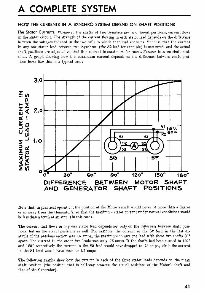
The Stator Currents: Whenever the shafts of two Synchros are in different positions, current flows
in the stator circuit. The strength of the current flowing in each stator lead depends on the difference
between the voltages induced in the two coils to which that lead connects. Suppose that the current
in any one stator lead between two Synchros (the S3 lead for example) is measured, and the actual
shaft positions are adjusted so that this current is maximum for each difference between shaft posi-
tions. A graph showing how this maximum current depends on the difference between shaft posi-
tions looks like this in a typical case:
18o"
DIFFERENCE BETWEEN MOTOR SHAFTAND GENERATOR SHAFT POSITIONS
Note that, in practical operation, the position of the Motor's shaft would never be more than a degree
or so away from the Generator's, so that the maximum stator current under normal conditions would
be less than a tenth of an amp. (in this case).
The current that flows in any one stator lead depends not only on the difference between shaft posi-
tions, but on the actual positions as well. For example, the current in the S2 lead in the last ex-
ample of the previous section was 1.5 amps., the maximum in any one lead with these two shafts 60°
apart. The current in the other two leads was only .75 amps. If the shafts had been turned to 120°
and 180° respectively the current in the S2 lead wculd have dropped to .75 amps., while the current
in the SI lead would have risen to 1.5 amps.
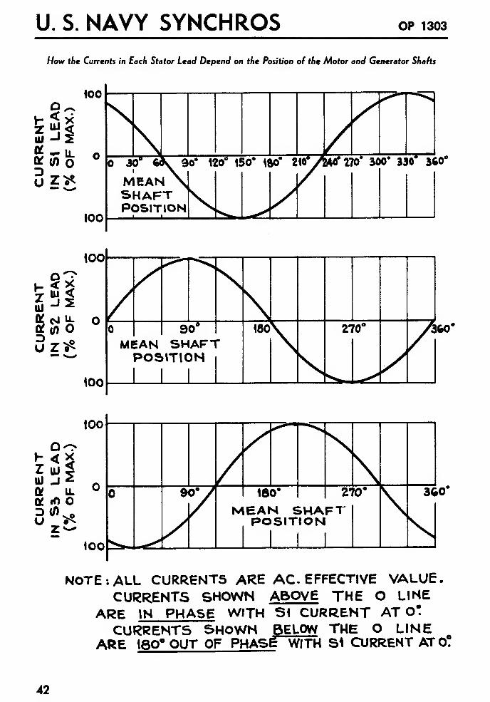
The following graphs show how the current in each of the three stator leads depends on the mean
shaft position (the position that is half-way between the actual positions of the Motor's shaft and
that of the Generator).
41
U. S. NAVY SYNCHROS OP 1303
How the Currents in Each Stator Lead Depend on the Position of the Motor and Generator Shafts
oV-<
3?
IL
o
too
too
MEANSHAFTPOSITION
360'
HZul
aOf
DU
Do
"JIL
(O o(0
3G0"
NOTE: ALL CURRENTS ARE AC EFFECTIVE VALUE.CURRENTS SHOWN ABOVE THE O LINE
ARE IN PHASE WITH Si CURRENT AT O*
CURRENTS SHOWN BELOW THE O LINEARE 18Q° OUT OF PHASE WITH S1 CURRENT ATO!
42
A COMPLETE SYSTEM
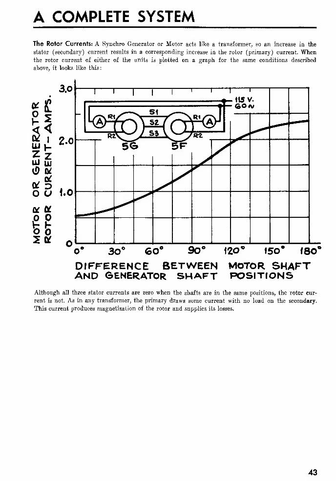
The Rotor Currents: A Synchro Generator or Motor acts like a transformer, so an increase in the
stator (secondary) current results in a corresponding increase in the rotor (primary) current. Whenthe rotor current of either of the units is plotted on a graph for the same conditions described
above, it looks like this:
O1-
3LUZLU
L*
O
3.0
£
<£ 2.0
zLU
3 1.0
SI
U. S. NAVY SYNCHROS OP 1303
THE TORQUE PRODUCED BY A SYNCHRO MOTOR
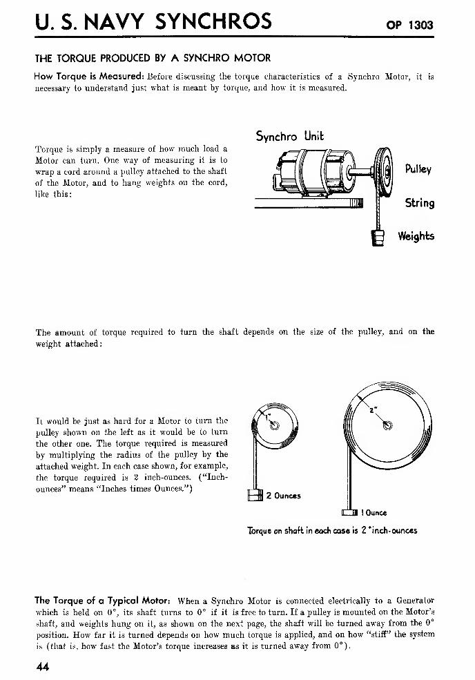
How Torque is Measured: Before discussing the torque characteristics of a Synchro Motor, it is
necessary to understand just what is meant by torque, and how it is measured.
Torque is simply a measure of how much load a
Motor can turn. One way of measuring it is to
wrap a cord around a pulley attached to the shaft
of the Motor, and to hang weights on the cord,
like this:
Synchro Unit
Pulley
String
g Weights
The amount of torque required to turn the shaft depends on the size of the pulley, and on the
weight attached:
It would be just as hard for a Motor to turn the
pulley shown on the left as it would be to turn
the other one. The torque required is measured
by multiplying the radius of the pulley by the
attached weight. In each case shown, for example,
the torque required is 2 inch-ounces. ("Inch-
ounces" means "Inches times Ounces.")2 Ounces
iTTa ] Ounce
Torque on shaft in each case is 2 'inch- ounces
The Torque of a Typical Motor: When a Synchro Motor is connected electrically to a Generator
which is held on 0°, its shaft turns to 0° if it is free to turn. If a pulley is mounted on the Motor's
shaft, and weights hung on it, as shown on the next page, the shaft will be turned away from the 0°
position. How far it is turned depends on how much torque is applied, and on how "stiff" the system
is (that is, how fast the Motor's torque increases as it is turned away from 0°).
44
A COMPLETE SYSTEM
115v.-60aj-A-C Supply{
SynchroGenerator
Weights/Synchro
Motor
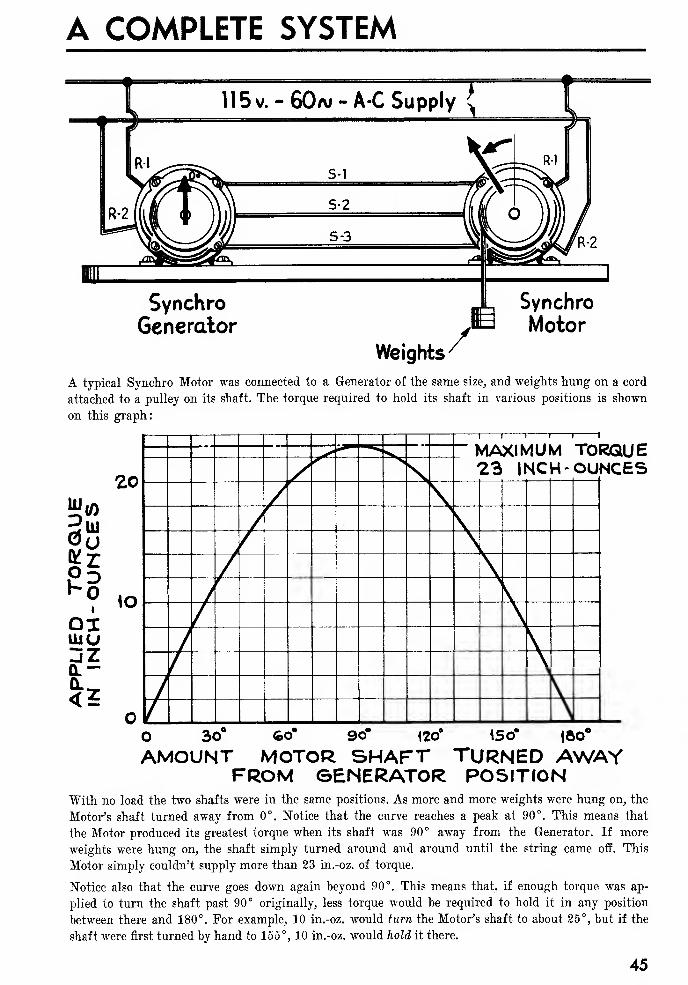
A typical Synchro Motor was connected to a Generator of the same size, and weights hung on a cord
attached to a pulley on its shaft. The torque required to hold its shaft in various positions is shown
on this graph:
%*HooiliiU
jZ
U. S. NAVY SYNCHROS OP 1303
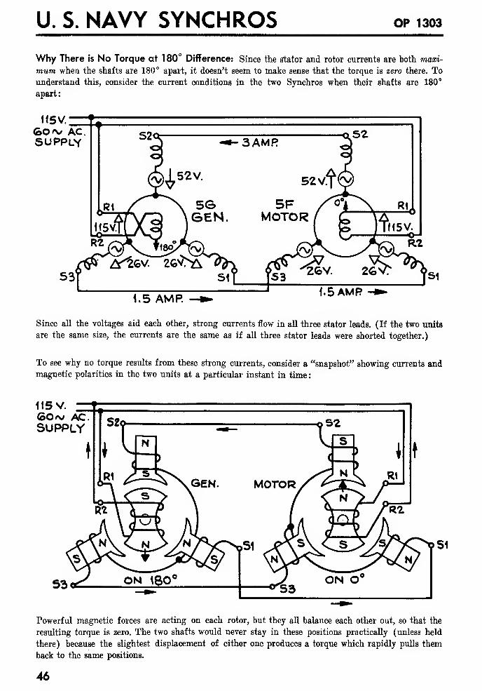
Why There is No Torque at 180° Difference: Since the stator and rotor currents are both maxi-
mum when the shafts are 180° apart, it doesn't seem to make sense that the torque is zero there. Tounderstand this, consider the current conditions in the two Synchros when their shafts are 180°
apart:
115V.
GO/v ACSUPPLY
1.5 AMP.
Since all the voltages aid each other, strong currents flow in all three stator leads. (If the two units
are the same size, the currents are the same as if all three stator leads were shorted together.)
To see why no torque results from these strong currents, consider a "snapshot" showing currents andmagnetic polarities in the two units at a particular instant in time
:
115 V.
GCw AC.SUPPLY
Powerful magnetic forces are acting on each rotor, but they all balance each other out, so that the
resulting torque is zero. The two shafts would never stay in these positions practically (unless held
there) because the slightest displacement of either one produces a torque which rapidly pulls them
back to the same positions.
46

A COMPLETE SYSTEM
The Torque Gradient: In practical operation the shaft of a Synchro Motor is never more than a
degree or so away from its Generator's shaft. This means that practically it isn't necessary to con-
sider the torque curve shown above to find the operating torque. For small angles the torque pro-
duced depends directly on the difference in shaft position. For example, if a torque of 0.4 in.-oz. pulls
the shafts 1° apart, 0.8 in.-oz. will pull them 2° apart, 4 in.-oz. will pull them 10° apart, and so on.
Because the torque required to pull a Synchro 1° off is such a convenient measure of the Synchro's
torque, it is given a special name : the "Torque Gradient." As soon as the Torque Gradient is known
for a Synchro Motor operating under certain conditions, the actual torque it will produce for any
normal difference in shaft positions can be found easily by multiplying the Torque Gradient by the
number of degrees of difference.
As an example the Torque Gradient of the Motor for which the above graph was drawn is .4 in.-
oz. per degree, when connected to a Generator of the same size. Thus the torque for 5° difference
is 5 x .4 or 2 in.-oz., which agrees with the graph.
The Unit Torque Gradient: A Motor is not always connected to a Generator of the same size. There
are many other possibilities, as will be described later. To provide a measure of a Synchro's perform-
ance which doesn't depend on where it is used, the "Unit Torque Gradient" is usually given. This is
simply the torque gradient which is measured when that Synchro is connected to another of the
same size and construction. In the case above, for example, the figure of .4 in.-oz. per degree would
be the Unit Torque Gradient of either the Motor or the Generator, since that was the Torque
Gradient measured when they were connected together, and they were the same size.
Unit Torque Gradient Depends on Internal Impedance: When a Motor is connected to a Gen-
erator of the same size, the amount of torque that is produced for a 1° difference in shaft positions
depends directly on the strength of the currents that flows in the stator coils. The strength of these
currents is determined by the amount of unbalanced voltage in each coil circuit, and by the internal
impedance of each Synchro.
The unbalanced stator voltages will be the same for any standard Synchro Motor or Generator, re-
gardless of size. The only thing that varies with the size of the Synchro is the internal impedance.
This brings out an important point: The thing that determines how much current flows, and howmuch torque is produced when two standard Synchros of the same size are connected together, is
simply the internal impedance of the stator circuits. Since the Unit Torque Gradient determines
the same thing, it follows that the Unit Torque Gradient of a Synchro is inversely proportional to
the internal impedance of its stator coils.
A small Synchro Motor or Generator has a low value of Unit Torque Gradient, and a high internal
impedance. A large one has a high Unit Torque Gradient, and a low internal impedance.
USING ONE GENERATOR TO DRIVE A NUMBER OF MOTORS
One large Generator may be used to drive a number of smaller Motors by connecting them in
parallel as shown at the top of the next page.
With this arrangement the impedance of the Generator's stator windings must be low enough so
that it can supply the necessary current to turn all the Motors without excessive voltage drop.
If any one Motor in a system like this has to supply more torque than the others, its shaft will lag
further behind the Generator's, producing less opposing voltage in its stator coils, so it will draw a
larger current than the others. This increased current will lower the Generator's output voltage, and
cause all the rest of the Motors on the system to lag more than before. For accuracy it is essential
that the Generator have low impedance (high Unit Torque Gradient) and that the load on each
Motor be as low as possible.
47
U. S. NAVY SYNCHROS OP 1303
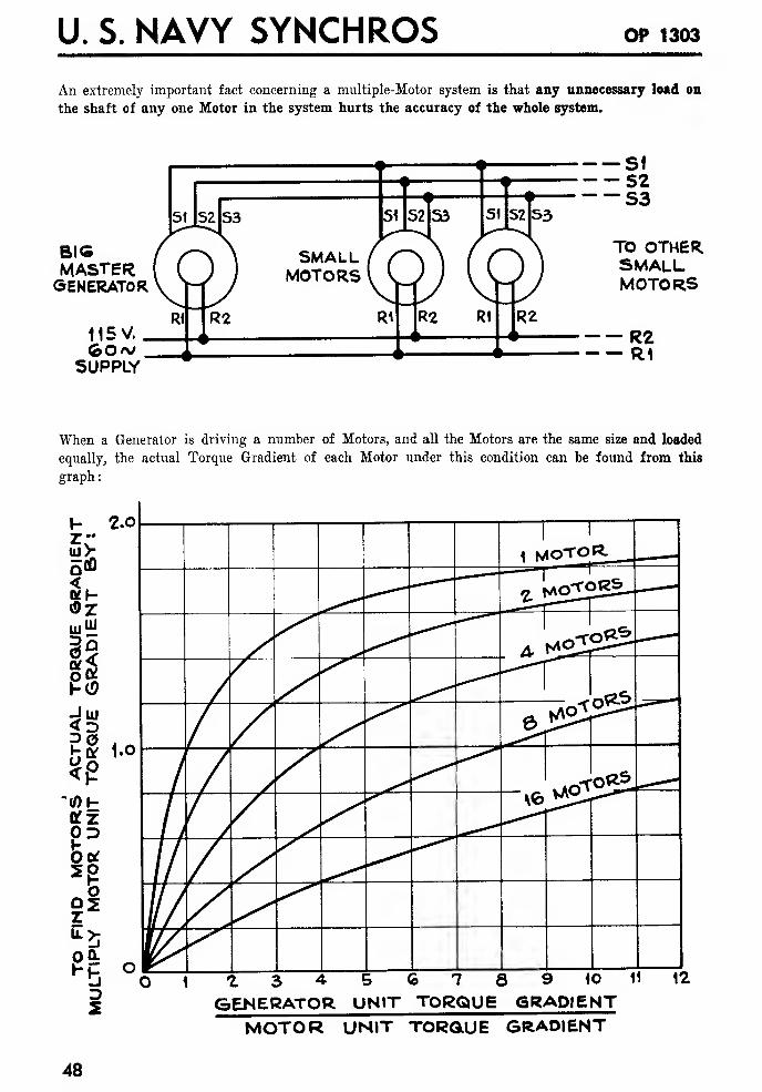
An extremely important fact concerning a multiple-Motor system is that any unnecessary load on
the shaft of any one Motor in the system hurts the accuracy of the whole system.
BIGMASTERGENERATOR
115V.
SUPPLY
— SI-52-S3
TO OTHERSMALLMOTORS
— R2— R1
When a Generator is driving a number of Motors, and all the Motors are the same size and loaded
equally, the actual Torque Gradient of each Motor under this condition can be found from this
graph
:
3
'(01-
ttz
D5
2.0
A COMPLETE SYSTEM
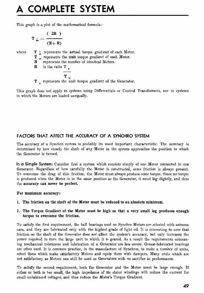
This graph is a plot of the mathematical formula
:
( 2R )
T ' =(N+R)
where T ^ represents the actual torque gradient of each Motor.
T represents the unit torque gradient of each Motor.
N represents the number of identical Motors.
R is the ratio T „
mT represents the unit torque gradient of the Generator.
This graph does not apply to systems using Differentials or Control Transformers, nor to systems
in which the Motors are loaded unequally.
FACTORS THAT AFFECT THE ACCURACY OF A SYNCHRO SYSTEM
The accuracy of a Synchro system is probably its most important characteristic. The accuracy is
determined by how closely the shaft of any Motor in the system approaches the position to which
the Generator is turned.
In a Simple System: Consider first a system which consists simply of one Motor connected to one
Generator. Regardless of how carefully the Motor is constructed, some friction is always present.
To overcome the drag of this friction, the Motor must always produce some torque. Since no torque
is produced when the Motor is in the same position as the Generator, it must lag slightly, and thus
the accuracy can never be perfect.
For maximum accuracy:
1. The friction on the shaft of the Motor must be reduced to an absolute minimum.
2. The Torque Gradient of the Motor must be high so that a very small lag produces enough
torque to overcome the friction.
To satisfy the first requirement, the ball bearings used on Synchro Motors are selected with extreme
care, and they are lubricated only with the highest grade of light oil. It is interesting to note that
friction on the shaft of the Generator does not affect the system's accuracy, but only increases the
power required to turn the large unit to which it is geared. As a result the requirements concern-
ing mechanical tolerances and lubrication of a Generator are less severe. Grease-lubricated bearings
are often used. It is common practice, in the manufacture of Synchros, to make a number of units,
select those which make satisfactory Motors and equip them with dampers. Many units which are
not satisfactory as Motors can still be used as Generators with no sacrifice in performance.
To satisfy the second requirement, both the Generator and the Motor must be large enough. If
either or both is too small, the high impedance of its stator windings will reduce the current for
small unbalanced voltages, and thus reduce the Motor's Torque Gradient.
49
U. S. NAVY SYNCHROS OP 1303
Practically, only two sizes of Synchro Motors are used in the Navy: (Note: An intermediate size is
shortly to be introduced.)
The smaller Motor (size 1) is used where accuracy is less important.
The larger Motor (size 5) is used in all positions where accuracy is required. When properly used
a 5 size Motor is accurate within a half a degree or better, and a 1 size Motor within two degrees
or so.
In a System Involving a Number of Motors: In such a system the accuracy with which each
Motor follows the master Generator is determined by the following factors:
1. The friction or other load on the shaft of that Motor.
2. The friction or other load on the shafts of all the other Motors. If any one Motor turns hard,
or becomes jammed, the accuracy of the whole system is affected.
3. The size of the Generator (its Unit Torque Gradient) as related to the number and size of the
Motors in the system. If too many Motors are connected to a Generator its output voltages are
reduced and excessive lag is produced in all the Motors in the system.
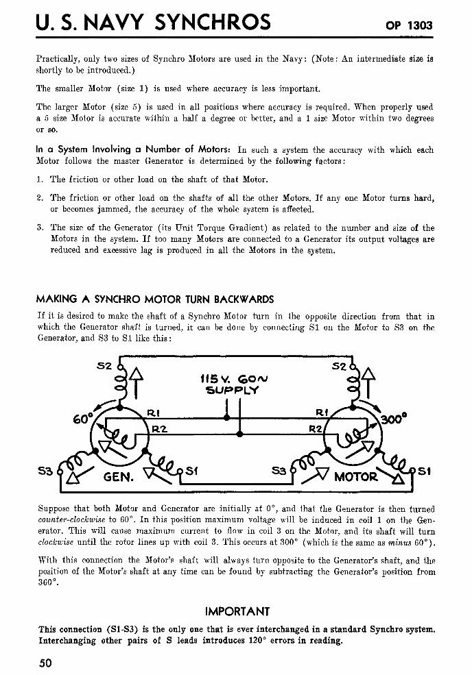
MAKING A SYNCHRO MOTOR TURN BACKWARDS
If it is desired to make the shaft of a Synchro Motor turn in the opposite direction from that in
which the Generator shaft is turned, it can be done by connecting SI on the Motor to S3 on the
Generator, and S3 to SI like this:
115 v. GO/vSUPPLY
1
^] >V MOTORS^?5'
Suppose that both Motor and Generator are initially at 0°, and that the Generator is then turned
counter-clockwise to 60°. In this position maximum voltage will be induced in coil 1 on the Gen-
erator. This will cause maximum current to flow in coil 3 on the Motor, and its shaft will turn
clockwise until the rotor lines up with coil 3. This occurs at 300° (which is the same as minus 60°).
With this connection the Motor's shaft will always turn opposite to the Generator's shaft, and the
position of the Motor's shaft at any time can be found by subtracting the Generator's position from360°.
IMPORTANT
This connection (S1-S3) is the only one that is ever interchanged in a standard Synchro system.
Interchanging other pairs of S leads introduces 120° errors in reading.
50
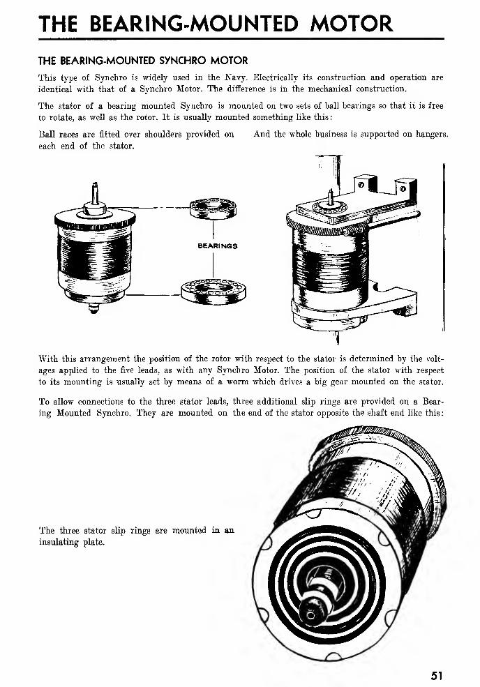
THE BEARING-MOUNTED MOTORTHE BEARING-MOUNTED SYNCHRO MOTOR
This type of Synchro is widely used in the Navy. Electrically its construction and operation are
identical with that of a Synchro Motor. The difference is in the mechanical construction.
The stator of a bearing mounted Synchro is mounted on two sets of ball bearings so that it is free
to rotate, as well as the rotor. It is usually mounted something like this
:
Ball races are fitted over shoulders provided on
each end of the stator.
And the whole business is supported on hangers.
With this arrangement the position of the rotor with respect to the stator is determined by the volt-
ages applied to the five leads, as with any Synchro Motor. The position of the stator with respect
to its mounting is usually set by means of a worm which drives a big gear mounted on the stator.
To allow connections to the three stator leads, three additional slip rings are provided on a Bear-
ing Mounted Synchro. They are mounted on the end of the stator opposite the shaft end like this
:
The three stator slip rings are mounted in an
insulating plate.
51
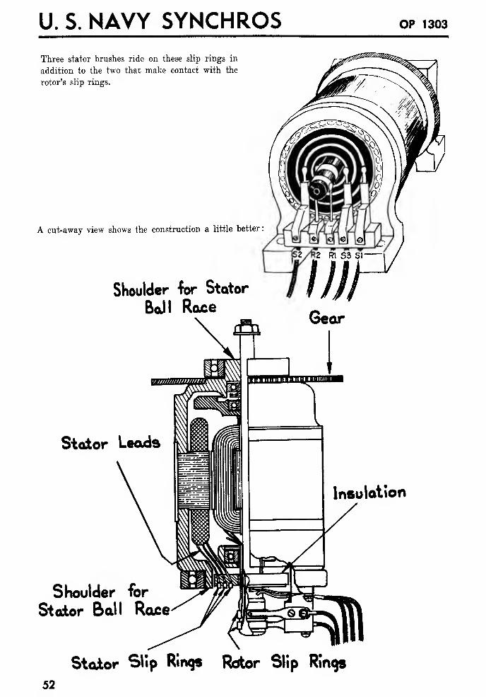
U. S. NAVY SYNCHROS OP 1303
Three stator brushes ride on these slip rings in
addition to the two that make contact with the
rotor's slip rings.
A cut-away view shows the construction a little better
:
Shoulder for Stator
Ball RaceGear
Stator Leads
Shoulder for
Stator Ball Race
Insulation
Stator Slip Rings Rotor Slip Rings
52
THE DIFFERENTIAL
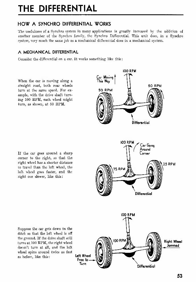
HOW A SYNCHRO DIFFERENTIAL WORKSThe usefulness of a Synchro system in many applications is greatly increased by the addition of
another member of the Synchro family, the Synchro Differential. This unit does, in a Synchro
system, very much the same job as a mechanical differential does in a mechanical system.
A MECHANICAL DIFFERENTIAL
Consider the differential on a car. It works something like this
:
100 RPM
When the car is moving along a
straight road, both rear wheels
turn at the same speed. For ex-
ample, with the drive shaft turn-
ing 100 RPM, each wheel might
turn, as shown, at 50 EPM.
Car Moving
This %xy
50 RPM
Differential
100 RPM
If the car goes around a sharp
corner to the right, so that the
right wheel has a shorter distance
to travel than the left wheel, the
left wheel goes faster, and the
right one slower, like this:
Car Going
Around
Comer
25 RPM
Differential
100 RPM
Suppose the car gets down in the
ditch so that the left wheel is off
the ground. If the drive shaft still
turns at 100 RPM, the right wheel
doesn't turn at all, and the left
wheel spins around twice as fast
as before, like this: Left Wheel
Free to—Turn
Right Wheel
Jammed
Differential
53
U. S. NAVY SYNCHROS OP 1303
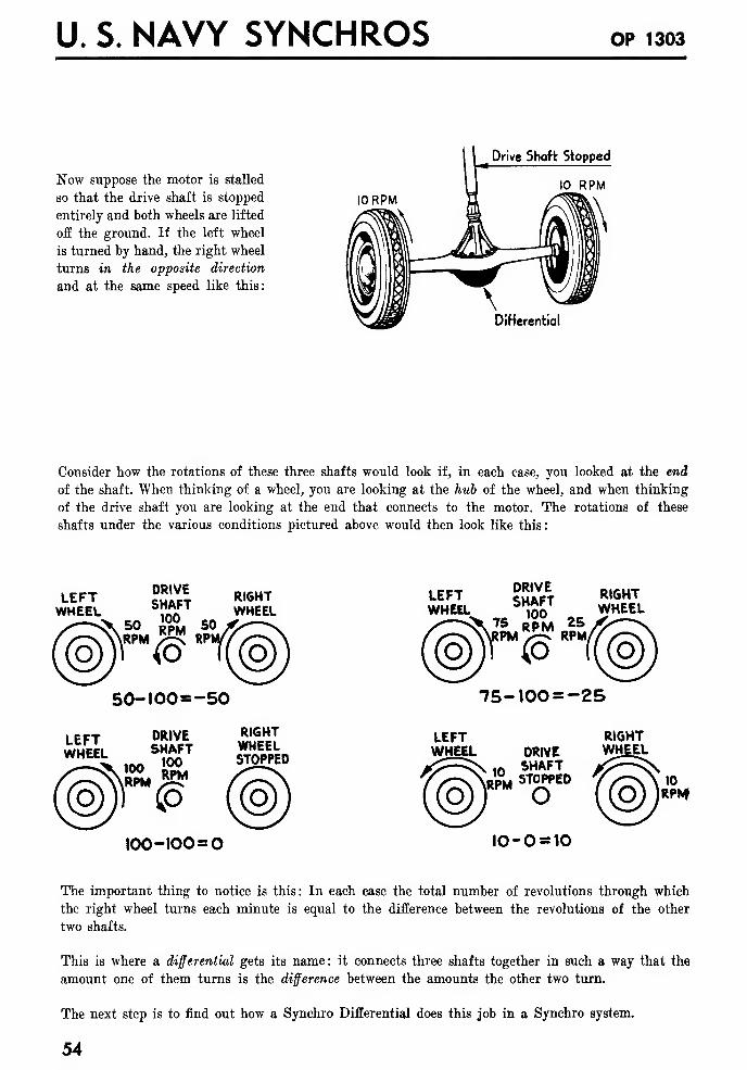
Drive Shaft Stopped
Now suppose the motor is stalled
so that the drive shaft is stopped
entirely and both wheels are lifted
off the ground. If the left wheel
is turned by hand, the right wheel
turns in the opposite direction
and at the same speed like this:
I0RPM
Differential
Consider how the rotations of these three shafts would look if, in each ease, you looked at the end
of the shaft. When thinking of a wheel, you are looking at the hub of the wheel, and when thinking
of the drive shaft you are looking at the end that connects to the motor. The rotations of these
shafts under the various conditions pictured above would then look like this
:
LEFTWHEEL
DRIVESHAFT
»> RP°M SORPM<s
RPI
RIGHTWHEEL
50-100=-50
LEFT ?Saft RI6HTWHEEL ,So WHEEL
75 RpM 25PM ™ RPM/
'<P
75-100 =-25
LEFTWHEEL
DRIVESHAFT
RPM
100-100 =
RIGHTWHEELSTOPPED
LEFTWHEEL
RPM
DRIVESHAFTSTOPPED
10-0 = 10
RIGHTWHEEL
The important thing to notice is this : In each case the total number of revolutions through which
the right wheel turns each minute is equal to the difference between the revolutions of the other
two shafts.
This is where a differential gets its name: it connects three shafts together in such a way that the
amount one of them turns is the difference between the amounts the other two turn.
The next step is to find out how a Synchro Differential does this job in a Synchro system.
54
THE DIFFERENTIAL
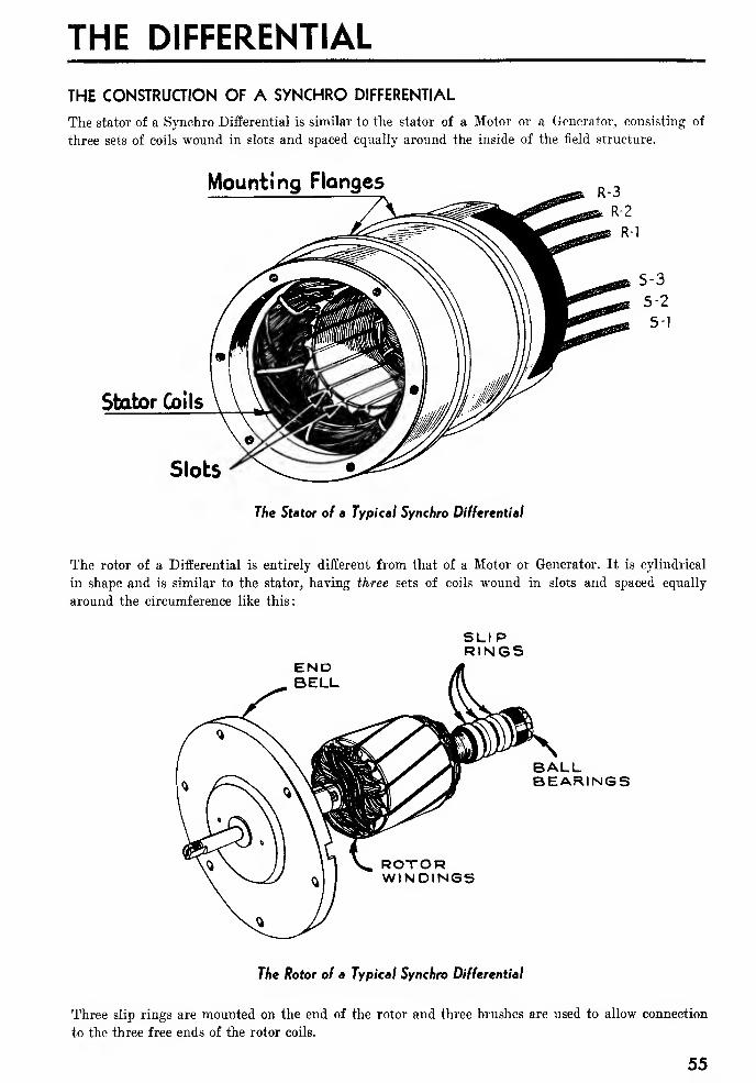
THE CONSTRUCTION OF A SYNCHRO DIFFERENTIAL
The stator of a Synchro Differential is similar to the stator of a Motor or a Generator, consisting of
three sets of coils wound in slots and spaced equally around the inside of the field structure.
Mounting Flanges
The Stator of a Typical Synchro Differential
The rotor of a Differential is entirely different from that of a Motor or Generator. It is cylindrical
in shape and is similar to the stator, having three sets of coils wound in slots and spaced equally
around the circumference like this:
END
SLIPRINGS
BALLBEARINGS
ROTORWINDINGS
The Rotor of a Typical Synchro Differential
Three slip rings are mounted on the end of the rotor and three brushes are used to allow connection
to the three free ends of the rotor coils.
55
U. S. NAVY SYNCHROS OP 1303
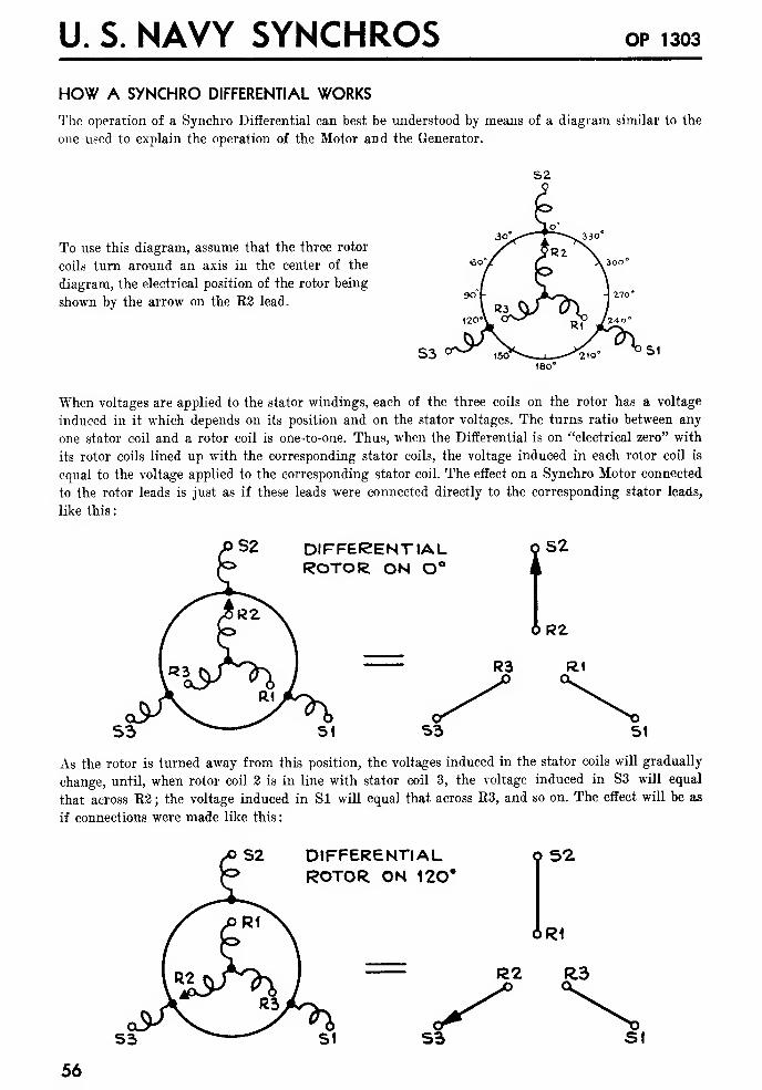
HOW A SYNCHRO DIFFERENTIAL WORKS
The operation of a Synchro Differential can best be understood by means of a diagram similar to the
one used to explain the operation of the Motor and the Generator.
S2
To use this diagram, assume that the three rotor
coils turn around an axis in the center of the
diagram, the electrical position of the rotor being
shown by the arrow on the R2 lead.
When voltages are applied to the stator windings, each of the three coils on the rotor has a voltage
induced in it which depends on its position and on the stator voltages. The turns ratio between any
one stator coil and a rotor coil is one-to-one. Thus, when the Differential is on "electrical zero" with
its rotor coils lined up with the corresponding stator coils, the voltage induced in each rotor coil is
equal to the voltage applied to the corresponding stator coil. The effect on a Synchro Motor connected
to the rotor leads is just as if these leads were connected directly to the corresponding stator leads,
like this:
DIFFERENTIALROTOR ON O l
S2
&R2
R3 R1
S3 51
As the rotor is turned away from this position, the voltages induced in the stator coils will gradually
change, until, when rotor coil 2 is in line with stator coil 3, the voltage induced in S3 will equal
that across R2 ; the voltage induced in Si will equal that across R3, and so on. The effect will be as
if connections were made like this
:
DIFFERENTIALROTOR ON 120'
9 52
6R1
R2 R.3
S3 St
56
THE DIFFERENTIAL
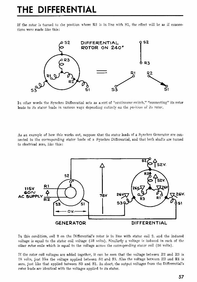
If the rotor is turned to the position where R2 is in line with SI, the effect will be as if connec-
tions were made like this
:
S2 DIFFERENTIALROTOR ON 240°
QS2
6 R3
R1 R2
S3 SI
In other words the Synchro Differential acts as a sort of "continuous switch," "connecting" its rotor
leads to its stator leads in various ways depending entirely on the position of its rotor.
As an example of how this works out, suppose that the stator leads of a Synchro Generator are con-
nected to the corresponding stator leads of a Synchro Differential, and that both shafts are turned
to electrical zero, like this:
nsv60/v A
AC SUPPLY '
^[52V.
GENERATOR DIFFERENTIAL
In this condition, coil 2 on the Differential's rotor is in line with stator coil 2, and the induced
voltage is equal to the stator coil voltage (52 volts). Similarly a voltage is induced in each of the
other rotor coils which is equal to the voltage across the corresponding stator coil (26 volts).
If the rotor coil voltages are added together, it can be seen that the voltage between R2 and R3 is
78 volts, just like the voltage applied between S3 and S3. Also the voltage between E3 and Rl is
zero, just like that applied between S3 and Si. In short, the output voltages from the Differential's
rotor leads are identical with the voltages applied to its stator.
57
U. S. NAVY SYNCHROS OP 1303
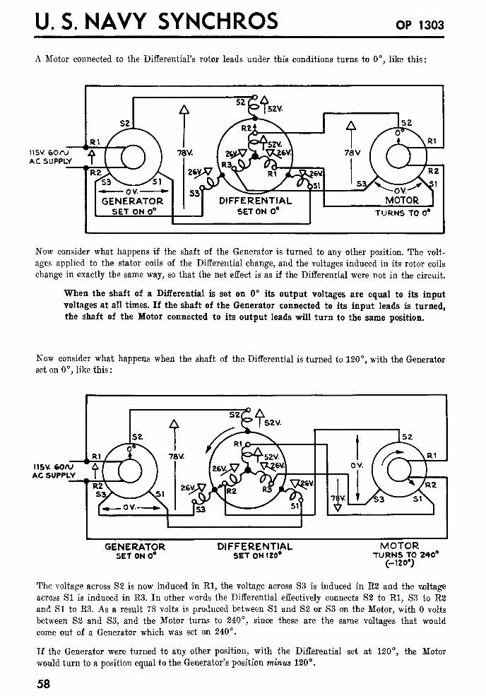
A Motor connected to the Differential's rotor leads under this conditions turns to 0°, like this:
115V &oroAC SUPPLY
Now consider what happens if the shaft of the Generator is turned to any other position. The volt-
ages applied to the stator coils of the Differential change, and the voltages induced in its rotor coils
change in exactly the same way, so that the net effect is as if the Differential were not in the circuit.
When the shaft of a Differential is set on 0° its output voltages are equal to its input
voltages at all times. If the shaft of the Generator connected to its input leads is turned,
the shaft of the Motor connected to its output leads will turn to the same position.
Now consider what happens when the shaft of the Differential is turned to 120°, with the Generator
set on 0°, like this:
115V. feoru
AC SUPPLY
GENERATORSET ON 8
DIFFERENTIALSET ON 120*
MOTORTURNS TO 240°
(-120')
The voltage across S2 is now induced in El, the voltage across S3 is induced in E2 and the voltage
across SI is induced in E3. In other words the Differential effectively connects S2 to El, S3 to B2and Si to E3. As a result 78 volts is produced between SI and S2 or S3 on the Motor, with volts
between S2 and S3, and the Motor turns to 240°, since these are the same voltages that would
come out of a Generator which was set on 240°.
If the Generator were turned to any other position, with the Differential set at 120°, the Motor
would turn to a position equal to the Generator's position minus 120°.
58
THE DIFFERENTIAL
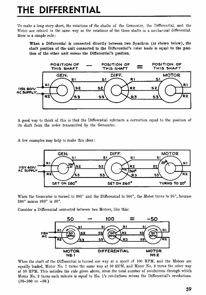
To make a long story short, the rotations of the shafts of the Generator, the Differential, and the
Motor are related in the same way as the rotations of the three shafts in a mechanical differential.
Here is a simple rule:
When a Differential is connected directly between two Synchros (as shown below), the
shaft position of the unit connected to the Differential's rotor leads is equal to the posi-
tion of the other unit minus the Differential's position.
115V. 60/VAC SUPPLY.
POSITION OFTHIS SHAFT
POSITION OFTHIS SHAFT
POSITION OFTHIS SHAFT
A good way to think of this is that the Differential subtracts a correction equal to the position of
its shaft from the order transmitted by the Generator.
A few examples may help to make this clear
:
ii5V. feoa;AC SUPPLY
When the Generator is turned to 280° and the Differential to 260°, the Motor turns to 20°, because
280° minus 260° is 20°.
Consider a Differential connected between two Motors, like this:
50 - 100 = -50
MOTORN2.1
DIFFERENTIAL MOTORN22
When the shaft of the Differential is turned one way at a speed of 100 KPM, and the Motors are
equally loaded, Motor No. 1 turns the same way at 50 EPM, and Motor No. 2 turns the other way
at 50 RPM. This satisfies the rule given above, since the total number of revolutions through which
Motor No. 2 turns each minute is equal to No. l's revolutions minus the Differential's revolutions.
(50-100 = -50.)
59

U. S. NAVY SYNCHROS OP 1303
With these connections, if No. 2's shaft is stopped, No. l's turns twice as fast; if the Differential
is stopped and No. 1 is turned one way at 10 EPM, No. 2 turns the same way at 10 RPM.
Suppose these three units were connected electrically as shown above, and mounted mechanically like
this:
LEFTWHEEL50 R.PM.
DRIVE SHAFT10O R.PM.
electricalConnections
RIGHTWHEEL50 R.PM.
. TO 115V.'AC SUPPLY
It is easy to see that they would give the same results as the mechanical differential that was de-
scribed before. This would not be a very practical way to drive a car, however, because of the large
units required, and the need for an AC supply. The advantage of the Synchro differential system
over the mechanical one is the fact that the units can be widely separated from each other without
any mechanical connection.
TO REVERSE THE EFFECT OF A DIFFERENTIAL'S SHAFT
The effect of the Differential's shaft position on the associated units can be reversed, by interchang-
ing both the S1-S3 connections and the E1-E3 connections like this:
POSITION OFTHIS SHAFT
POSITION OF —THIS SHAFT — POSITION OF
THIS SHAFT
JI5V.AC
SUPPLY
GENERATOR. DIFFERENTIAL
With reversed connection the rule given above is modified as follows
:
If both the S1-S3 and the R1-R3 connections to a Differential are interchanged, the shaft
position of the unit connected to the Differential's rotor leads is equal to the position of the
other unit plus the Differential's position.
In other words, the Differential now adds a correction equal to its position to the order transmitted
by the Generator.
60
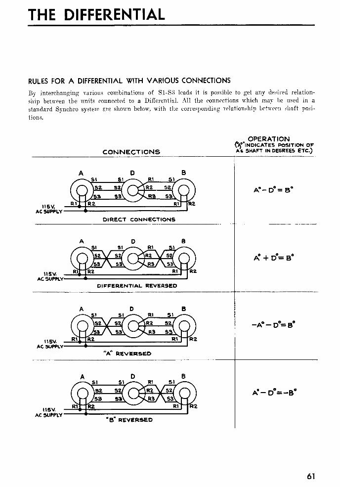
THE DIFFERENTIAL
RULES FOR A DIFFERENTIAL WITH VARIOUS CONNECTIONS
By interchanging various combinations of S1-S3 leads it is possible to get any desired relation-
ship between the units connected to a Differential. All the connections which may be used in a
standard Synchro system are shown below, with the corresponding relationship between shaft posi-
tions.
CONNECTIONS
. OPERATIONW'lNDICATES POSITION OFAs SHAFT IN DEGREES ETC.)
II 5V.
AC SUPPLY
A°-D°=B S
DIRECT CONNECTIONS
115V.AC SUPPLY'
A + D = B
DIFFERENTIAL REVERSED
U5V.AC SUPPLY
-A°-D°=B°
115V.
AC SUPPLY
A'-D°=-B°
"B* REVERSED
61
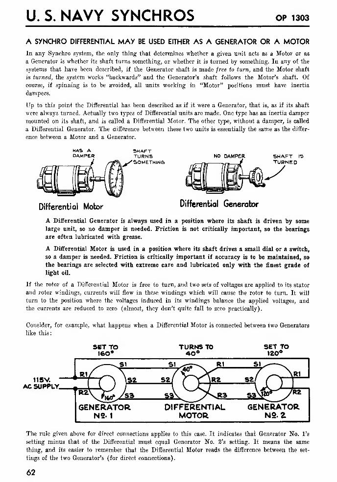
U. S. NAVY SYNCHROS OP 1303
A SYNCHRO DIFFERENTIAL MAY BE USED EITHER AS A GENERATOR OR A MOTORIn any Synchro system, the only thing that determines whether a given unit acts as a Motor or as
a Generator is whether its shaft turns something, or whether it is turned by something. In any of the
systems that have been described, if the Generator shaft is made free to turn, and the Motor shaft
is turned, the system works "backwards" and the Generator's shaft follows the Motor's shaft. Of
course, if spinning is to be avoided, all units working in "Motor" positions must have inertia
dampers.
Up to this point the Differential has been described as if it were a Generator, that is, as if its shaft
were always turned. Actually two types of Differential units are made. One type has an inertia damper
mounted on its shaft, and is called a Differential Motor. The other type, without a damper, is called
a Differential Generator. The difference between these two units is essentially the same as the differ-
ence between a Motor and a Generator.
SHAFTTURNS
-/"SOMETHINGNO DAMPER SHAFT IS
TURNED
Differential Motor Differential Generator
A Differential Generator is always used in a position where its shaft is driven by some
large unit, so no damper is needed. Friction is not critically important, so the bearings
are often lubricated with grease.
A Differential Motor is used in a position where its shaft drives a small dial or a switch,
so a damper is needed. Friction is critically important if accuracy is to be maintained, so
the bearings are selected with extreme care and lubricated only with the finest grade of
light oil.
If the rotor of a Differential Motor is free to turn, and two sets of voltages are applied to its stator
and rotor windings, currents will flow in these windings which will cause the rotor to turn. It will
turn to the position where the voltages induced in its windings balance the applied voltages, and
the currents are reduced to zero (almost, they don't quite fall to zero practically).
Consider, for example, what happens when a Differential Motor is connected between two Generators
like this:
SET TO160°
TURNS TO40*
SET TO120°
115V.AC SUPPLY.
GENERATORN2. 1
DIFFERENTIALMOTOR
GENERATORN2. Z
The rule given above for direct connections applies to this case. It indicates that Generator No. l's
setting minus that of the Differential must equal Generator No. 2's setting. It means the same
thing, and its easier to remember that the Differential Motor reads the difference between the set-
tings of the two Generator's (for direct connections).
62
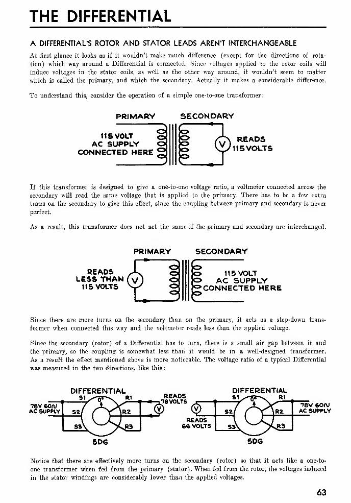
THE DIFFERENTIAL
A DIFFERENTIAL'S ROTOR AND STATOR LEADS AREN'T INTERCHANGEABLE
At first glance it looks as if it wouldn't make much difference (except for the directions of rota-
tion) which way around a Differential is connected. Since voltages applied to the rotor coils will
induce voltages in the stator coils, as well as the other way around, it wouldn't seem to matter
which is called the primary, and which the secondary. Actually it makes a considerable difference.
To understand this, consider the operation of a simple one-to-one transformer:
PRIMARY
US VOLTAC SUPPLY
CONNECTED HERE
SECONDARY
READS115VOLTS
If this transformer is designed to give a one-to-one voltage ratio, a voltmeter connected across the
secondary will read the same voltage that is applied to the primary. There has to be a few extra
turns on the secondary to give this effect, since the coupling between primary and secondary is never
perfect.
As a result, this transformer does not act the same if the primary and secondary are interchanged.
PRIMARY
READSLESS THAN115 VOLTS
SECONDARY
115 VOLTAC SUPPLY
CONNECTED HERE
Since there are more turns on the secondary than on the primary, it acts as a step-down trans-
former when connected this way and the voltmeter reads less than the applied voltage.
Since the secondary (rotor) of a Differential has to turn, there is a small air gap between it and
the primary, so the coupling is somewhat less than it would be in a well-designed transformer.
As a result the effect mentioned above is more noticeable. The voltage ratio of a typical Differential
was measured in the two directions, like this
:
DIFFERENTIAL
78V 6<WAC SUPPLY
READS78VOLTS
DIFFERENTIALS1^-7j5-\ R1
5D6
READS66 VOLTS
5DG
76V feorvAC SUPPLY
Notice that there are effectively more turns on the secondary (rotor) so that it acts like a one-to-
one transformer when fed from the primary (stator). When fed from the rotor, the voltages induced
in the stator windings are considerably lower than the applied voltages.
63
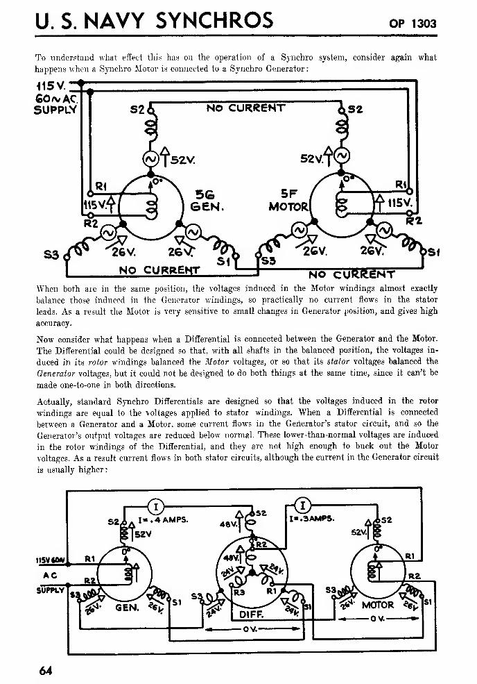
U. S. NAVY SYNCHROS OP 1303
To understand what effect this has on the operation of a Synchro system, consider again what
happens when a Synchro Motor is connected to a Synchro Generator
:
<15V.
60* ACSUPPLY
NO CURRENTWhen both are in the same position, the voltages induced in the Motor windings almost exactly
balance those induced in the Generator windings, so practically no current flows in the stator
leads. As a result the Motor is very sensitive to small changes in Generator position, and gives high
accuracy.
Now consider what happens when a Differential is connected between the Generator and the Motor.
The Differential could be designed so that, with all shafts in the balanced position, the voltages in-
duced in its rotor windings balanced the Motor voltages, or so that its stator voltages balanced the
Generator voltages, but it could not be designed to do both things at the same time, since it can't be
made one-to-one in both directions.
Actually, standard Synchro Differentials are designed so that the voltages induced in the rotor
windings are equal to the voltages applied to stator windings. When a Differential is connected
between a Generator and a Motor, some current flows in the Generator's stator circuit, and so the
Generator's output voltages are reduced below normal. These lower-than-normal voltages are induced
in the rotor windings of the Differential, and they are not high enough to buck out the Motor
voltages. As a result current flows in both stator circuits, although the current in the Generator circuit
is usually higher
:
115V
64
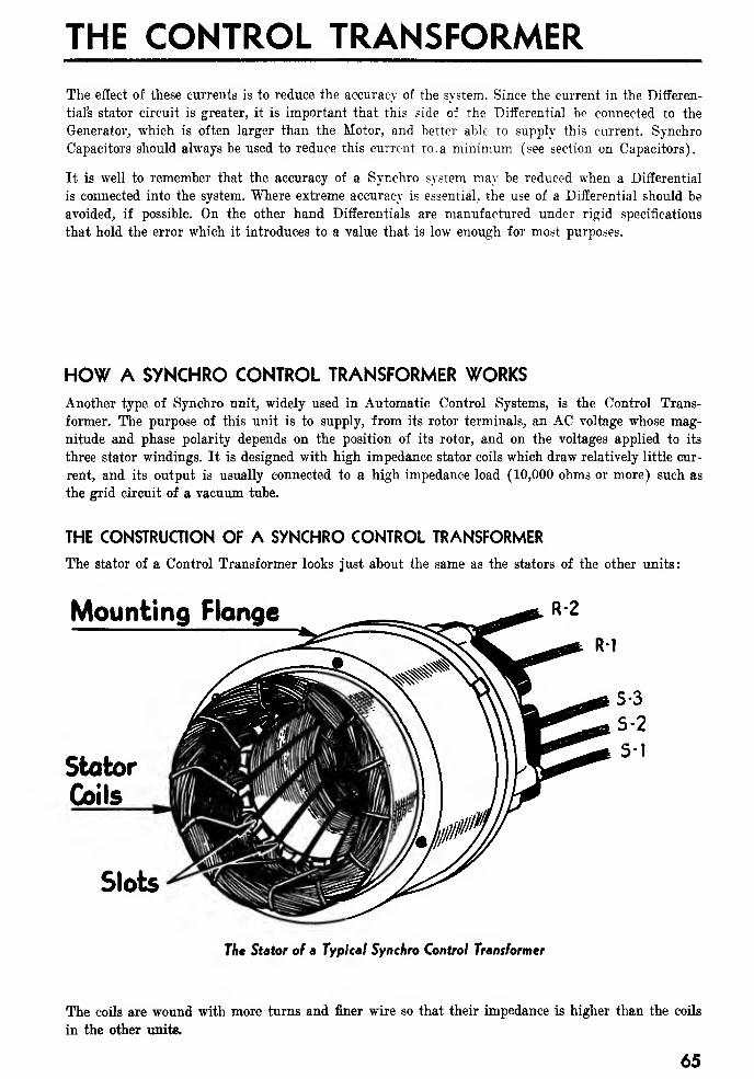
THE CONTROL TRANSFORMERThe effect of these currents is to reduce the accuracy of the system. Since the current in the Differen-
tial's stator circuit is greater, it is important that this side of the Differential be connected to the
Generator, which is often larger than the Motor, and better able to supply this current. Synchro
Capacitors should always be used to reduce this current to. a minimum (see section on Capacitors).
It is well to remember that the accuracy of a Synchro system may be reduced when a Differential
is connected into the system. Where extreme accuracy is essential, the use of a Differential should be
avoided, if possible. On the other hand Differentials are manufactured under rigid specifications
that hold the error which it introduces to a value that is low enough for most purposes.
HOW A SYNCHRO CONTROL TRANSFORMER WORKSAnother type of Synchro unit, widely used in Automatic Control Systems, is the Control Trans-
former. The purpose of this unit is to supply, from its rotor terminals, an AC voltage whose mag-
nitude and phase polarity depends on the position of its rotor, and on the voltages applied to its
three stator windings. It is designed with high impedance stator coils which draw relatively little cur-
rent, and its output is usually connected to a high impedance load (10,000 ohms or more) such as
the grid circuit of a vacuum tube.
THE CONSTRUCTION OF A SYNCHRO CONTROL TRANSFORMER
The stator of a Control Transformer looks just about the same as the stators of the other units
:
Mounting Flange
Stator
Coils
Slots
The Stator of a Typical Synchro Control Transformer
The coils are wound with more turns and finer wire so that their impedance is higher than the coils
in the other units.
65
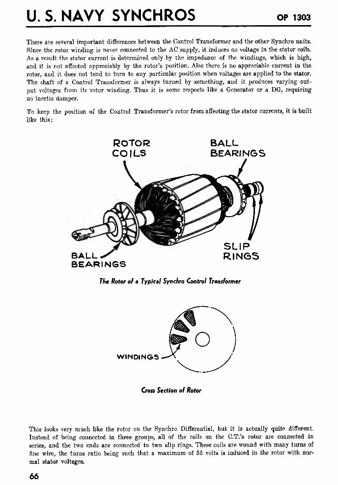
U. S. NAVY SYNCHROS OP 1303
There are several important differences between the Control Transformer and the other Synchro units.
Since the rotor winding is never connected to the AC supply, it induces no voltage in the stator coils.
As a result the stator current is determined only by the impedance of the windings, which is high,
and it is not affected appreciably by the rotor's position. Also there is no appreciable current in the
rotor, and it does not tend to turn to any particular position when voltages are applied to the stator.
The shaft of a Control Transformer is always turned by something, and it produces varying out-
put voltages from its rotor winding. Thus it is some respects like a Generator or a DG, requiring
no inertia damper.
To keep the position of the Control Transformer's rotor from affecting the stator currents, it is built
like this:
ROTORCOILS
BALLBEARINGS
BALLBEARINGS
SLIPRINGS
The Rotor of a Typical Synchro Control Transformer
WINDINGS
Cross Section of Rotor
This looks very much like the rotor on the Synchro Differential, but it is actually quite different.
Instead of being connected in three groups, all of the coils on the C.T.'s rotor are connected in
series, and the two ends are connected to two slip rings. These coils are wound with many turns of
fine wire, the turns ratio being such that a maximum of 55 volts is induced in the rotor with nor-
mal stator voltages.
66
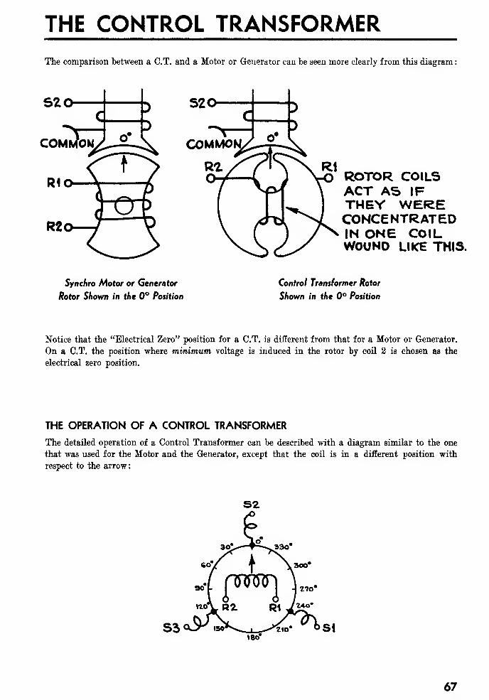
THE CONTROL TRANSFORMERThe comparison between a C.T. and a Motor or Generator can be seen more clearly from this diagram
:
S20
COMMON
ROTOR COILSACT AS IFTHEY WERECONCENTRATEDIN ONE COILWOUND LIKE THIS.
Synchro Motor or Generator
Rotor Shown in the 0° Position
Control Transformer Rotor
Shown in the 0° Position
Notice that the "Electrical Zero" position for a C.T. is different from that for a Motor or Generator.
On a C.T. the position where minimum voltage is induced in the rotor by coil 2 is chosen as the
electrical zero position.
THE OPERATION OF A CONTROL TRANSFORMER
The detailed operation of a Control Transformer can be described with a diagram similar to the one
that was used for the Motor and the Generator, except that the coil is in a different position with
respect to the arrow:
S2
67
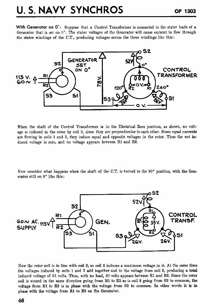
U. S. NAVY SYNCHROS OP 1303
With Generator on 0°: Suppose that a Control Transformer is connected to the stator leads of a
Generator that is set on 0°. The stator voltages of the Generator will cause current to flow through
the stator windings of the C.T., producing voltages across the three windings like this:
115 V.Go A/
CONTROLTRANSFORMER
When the shaft of the Control Transformer is in the Electrical Zero position, as shown, no volt-
age is induced in the rotor by coil 2, since they are perpendicular to each other. Since equal currents
are flowing in coils 1 and 3, they induce equal and opposite voltages in the rotor. Thus the net in-
duced voltage is zero, and no voltage appears between El and B2.
Now consider what happens when the shaft of the C.T. is turned to the 90° position, with the Gen-
erator still on 0° like this
:
oS2
Goaj ACSUPPLY 115V.J
CONTROLTRANSF
St
Now the rotor coil is in line with coil 2, so coil 2 induces a maximum voltage in it. At the same time
the voltages induced by coils 1 and 3 add together and to the voltage from coil 2, producing a total
induced voltage of 55 volts. Thus, with no load, 55 volts appears between Kl and E2. Since the rotor
coil is wound in the same direction going from Bl to B2 as is coil 2 going from S2 to common, the
voltage from El to E2 is in phase with the voltage from S2 to common. In other words it is in
phase with the voltage from El to B2 on the Generator.
68
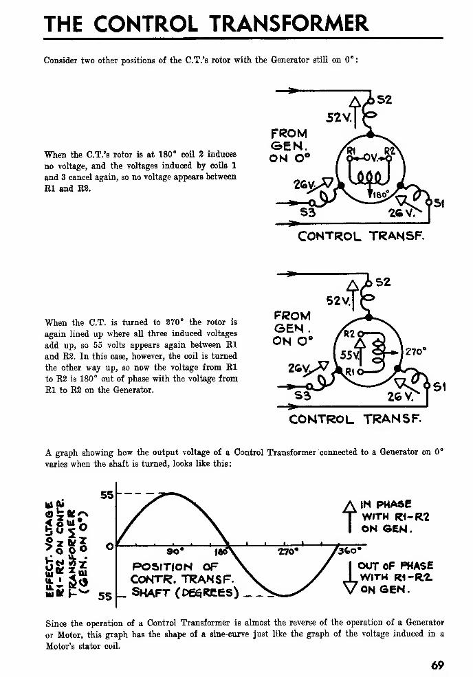
THE CONTROL TRANSFORMER
Consider two other positions of the C.T.'s rotor with the Generator still on 0"
When the C.T.'s rotor is at 180" coil 2 induces
no voltage, and the voltages induced by coils 1
and 3 cancel again, so no voltage appears between
El and B2.
FROM3EN.ON 0°
CONTROL TRANSF.
When the C.T. is turned to 270° the rotor is
again lined up where all three induced voltages
add up, so 55 volts appears again between El
and B2. In this case, however, the coil is turned
the other way up, so now the voltage from El
to B2 is 180° out of phase with the voltage from
El to B2 on the Generator.
FROMGEM.ON O
CONTROL TRANSF.
A graph showing how the output voltage of a Control Transformer connected to a Generator on C
varies when the shaft is turned, looks like this
:
III pi
sis*
55
IN PHASEWITH R1-R2ON GEN.
9o* i
POSITION OFcontr. transf.shaft (degrees)
OUT OF PHASEWITH R1-R2.ONSEN.
Since the operation of a Control Transformer is almost the reverse of the operation of a Generator
or Motor, this graph has the shape of a sine-curve just like the graph of the voltage induced in a
Motor's stator coil.
69
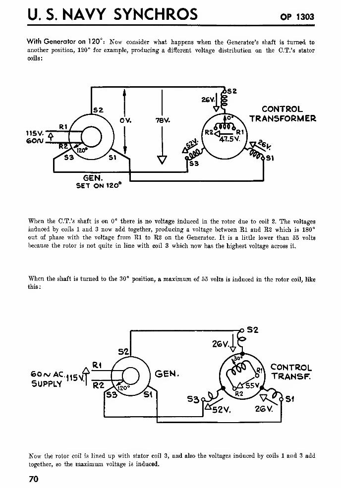
U. S. NAVY SYNCHROS OP 1303
With Generator on 1 20 : Now consider what happens when the Generator's shaft is turned to
another position, 120° for example, producing a different voltage distribution on the C.T.'s stator
coils:
115V.60A/
CONTROLTRANSFORMER
SET ON 12C
When the C.T.'s shaft is on 0° there is no voltage induced in the rotor due to coil 2. The voltages
induced by coils 1 and 3 now add together, producing a voltage between Rl and R2 which is 180°
out of phase with the voltage from Rl to R2 on the Generator. It is a little lower than 55 volts
because the rotor is not quite in line with coil 3 which now has the highest voltage across it.
When the shaft is turned to the 30° position, a maximum of 55 volts is induced in the rotor coil, like
this:
60/vAC.SUPPLY
115VX
S2
CONTROLTRANS F.
Now the rotor coil is lined up with stator coil 3, and also the voltages induced by coils 1 and 3 add
together, so the maximum voltage is induced.
70
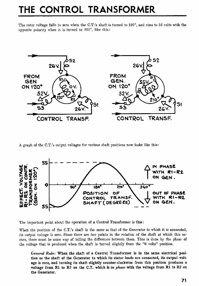
THE CONTROL TRANSFORMER
The rotor voltage falls to zero when the C.T.'s shaft is turned to 120°, and rises to 55 volts with the
opposite polarity when it is turned to 210°, like this:
FROMGENON 120°
52V
FROMGEN.OH 12o°
52 V.
CONTROL TRANSF. CONTROL TRANSF.
A graph of the C.T.'s output voltages for various shaft positions now looks like this
:
IN PHASEWITH R1-R2ON GEN .
OUT OF PHASEWITH R1-R2.ON GEN.
The important point about the operation of a Control Transformer is this :
When the position of the C.T.'s shaft is the same as that of the Generator to which it is connected,
its output voltage is zero. Since there are two points in the rotation of the shaft at which this oc-
curs, there must be some way of telling the difference between them. This is done by the phase of
the voltage that is produced when the shaft is turned slightly from the "0 volts" position.
General Rule: When the shaft of a Control Transformer is in the same electrical posi-
tion as the shaft of the Generator to which its stator leads are connected, its output volt-
age is zero, and turning its shaft slightly counter-clockwise from this position produces a
voltage from Rl to R2 on the C.T. which is ire phase with the voltage from Rl to R2 on
the Generator.
71

U. S. NAVY SYNCHROS OP 1303
USING A DIFFERENTIAL GENERATOR AS A CONTROL TRANSFORMER
The accuracy of any Synchro system depends, among other things, on how closely the Generator's
output voltages follow the normal sine-curve variation as its rotor is turned. When the stator leads
of a Control Transformer are connected across the output of a Generator the balance between these
three voltages is not seriously affected, provided the currents drawn by the three windings of the
Control Transformer are balanced.
As long as the load impedance across the rotor leads of the Control Transformer is fairly high
(10,000 ohms or more) the position of the rotor has no effect on the balance of the stator currents.
If an attempt is made to supply a lower impedance load the current in the rotor circuit reacts on
the stator currents, and may seriously unbalance the system.
Much the best answer to this problem is to arrange things so that the Control Transformer works
into a high-impedance load. In some cases where this was impossible, a Differential Generator has
been used in place of a Control Transformer like this:
115V 60/VAC SUPPLY
GENERATOR DIFFERENTIALGENERATOR
EXTERNALLOAD
MPEDANCE«3>
ADDED LOADS WHOSEIMPEDANCE EQUALS THATOF EXTERNAL LOAD.
With this connection the voltage between El and R3 on the DG varies in the same way as does
the voltage between Rl and R2 on a Control Transformer. Due to the balanced load on the DG'srotor, the currents that flow in the rotor windings do not unbalance the stator currents as the rotor
is turned.
This arrangement has the severe disadvantage that the DG requires a great deal more exciting cur-
rent than does a CT. For example, a 5DG with this connection might draw as much as 0.6 amps,
from the Generator, as compared with perhaps 0.04 amps, for a CT.
HOW SYNCHRO CAPACITORS (SYNCHRO "EXCITERS") ARE USED
In early Synchro systems these currents were reduced by connecting a free-running Motor, called an
"Induction Exciter" into the system. This supplied some of the current and reduced the load on the
Generator.
In all present Synchro systems this job is done by Synchro Capacitors (which are sometimes called
"Capacitor Exciters" or simply "Exciters"). A Synchro Capacitor of the proper size is connected to
the stator leads of every Differential or Control Transformer in the system, reducing its current
drain and improving the performance. It is important to understand the effect of these capacitors.
72
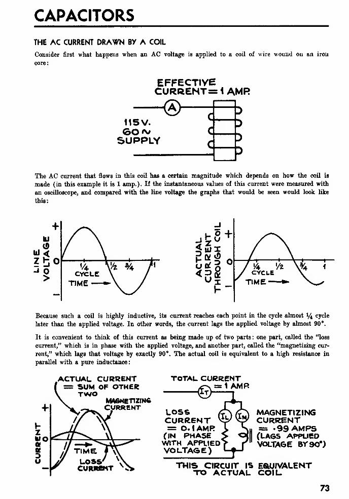
CAPACITORS
THE AC CURRENT DRAWN BY A COIL
Consider first what happens when an AC voltage is applied to a coil of wire wound on an iron
core:
EFFECTIVECURRENT= i AMR
<5>115V.
SUPPLY
The AC current that flows in this coil has a certain magnitude which depends on how the coil is
made (in this example it is 1 amp.). If the instantaneous values of this current were measured with
an oscilloscope, and compared with the line voltage the graphs that would be seen would look like
this:
Because such a coil is highly inductive, its current reaches each point in the cycle almost 14 cycle
later than the applied voltage. In other words, the current lags the applied voltage by almost 90°.
It is convenient to think of this current as being made up of two parts : one part, called the "loss
current," which is in phase with the applied voltage, and another part, called the "magnetizing cur-
rent," which lags that voltage by exactly 90°. The actual coil is equivalent to a high resistance in
parallel with a pure inductance:
.ACTUAL CURRENT= SUM OF OTHERTWO
MAGNETIZINGCURRENT
TOTAL CURRENT= 1 AMR
LOSSCURRENT= O.I AMR(IN PHASEWITH APPLIEDVOLTAGE)
MAGNETIZINGCURRENT= .99 AMPS(LA6S APPLIEDVOLTAGE 8Y90*)
THIS CIRCUIT ISTO ACTUAL
EQUIVALENTCOIL
73
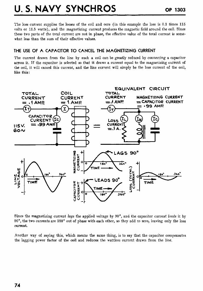
U. S. NAVY SYNCHROS OP 1303
The loss current supplies the losses of the coil and core (in this example the loss is 0.1 times 115
volts or 11.5 watts), and the magnetizing current produces the magnetic field around the coil. Since
these two parts of the total current are not in phase, the effective value of the total current is some-
what less than the sum of their effective values.
THE USE OF A CAPACITOR TO CANCEL THE MAGNETIZING CURRENT
The current drawn from the line by such a coil can be greatly reduced by connecting a capacitor
across it. If the capacitor is selected so that it draws a current equal to the magnetizing current of
the coil, it will cancel this current, and the line current will simply be the loss current of the coil,
like this:
TOTALCURRENT= . 1 AMR
-<©
COILCURRENT= A AMR©-
CAPACITORCURRENT (IC
l,5v/ =.99 AMR60>v C.
C.
}
}
J
}
EQUIVALENT CIRCUITTOTALCURRENT MAGNETIZING CURRENT=s.4 AMR = CAPACITOR CURRENT/T\ = «99 AMR
LOSS (Ju
currentI= .1A
LAGS 90*
5 o
K3u
TIME
360'
Since the magnetizing current lags the applied voltage by 90°, and the capacitor current leads it by
90°, the two currents are 180° out of phase with each other, so they add to zero, leaving only the loss
current.
Another way of saying this, which means the same thing, is to say that the capacitor compensates
the lagging power factor of the coil and reduces the wattless current drawn from the line.
74
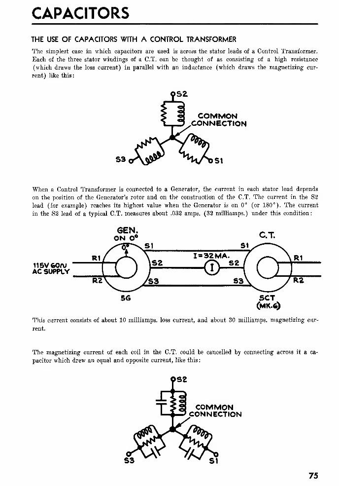
CAPACITORS
THE USE OF CAPACITORS WITH A CONTROL TRANSFORMER
The simplest case in which capacitors are used is across the stator leads of a Control Transformer.
Each of the three stator windings of a C.T. can be thought of as consisting of a high resistance
(which draws the loss current) in parallel with an inductance (which draws the magnetizing cur-
rent) like this
:
COMMONCONNECTION
When a Control Transformer is connected to a Generator, the current in each stator lead depends
on the position of the Generator's rotor and on the construction of the C.T. The current in the S2
lead (for example) reaches its highest value when the Generator is on 0° (or 180°). The current
in the S2 lead of a typical C.T. measures about .032 amps. (32 milliamps.) under this condition:
115V GQfVAC SUPPLY
5CT(MK.6)
This current consists of about 10 milliamps. loss current, and about 30 milliamps. magnetizing cur-
rent.
The magnetizing current of each coil in the C.T. could be cancelled by connecting across it a ca-
pacitor which drew an equal and opposite current, like this
:
COMMONCONNECTION
75
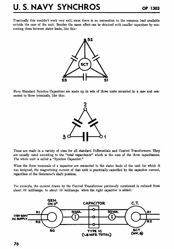
U. S. NAVY SYNCHROS OP 1303
Practically this wouldn't work very well, since there is no connection to the common lead available
outside the case of the unit. Besides the same effect can be obtained with smaller capacitors by con-
necting them between stator leads, like this
:
Navy Standard Synchro Capacitors are made up in sets of three units mounted in a case and con-
nected to three terminals, like this:
AThese are made in a variety of sizes for all standard Differentials and Control Transformers. They
are usually rated according to the "total capacitance" which is the sum of the three capacitances.
The whole unit is called a "Synchro Capacitor."
When the three terminals of a capacitor are connected to the stator leads of the unit for which it
was designed, the magnetizing current of that unit is practically cancelled by the capacitor current,
regardless of the Generator's shaft position.
For example, the current drawn by the Control Transformer previously mentioned is reduced from
about 32 milliamps. to about 10 milliamps. when the right capacitor is added
:
115VCOMAC SUPPLY,
76
GEN.ONO* CAPACITOR
TYPE 1C(1.8 MFD. TOTAL)
5CT(MK.fc)
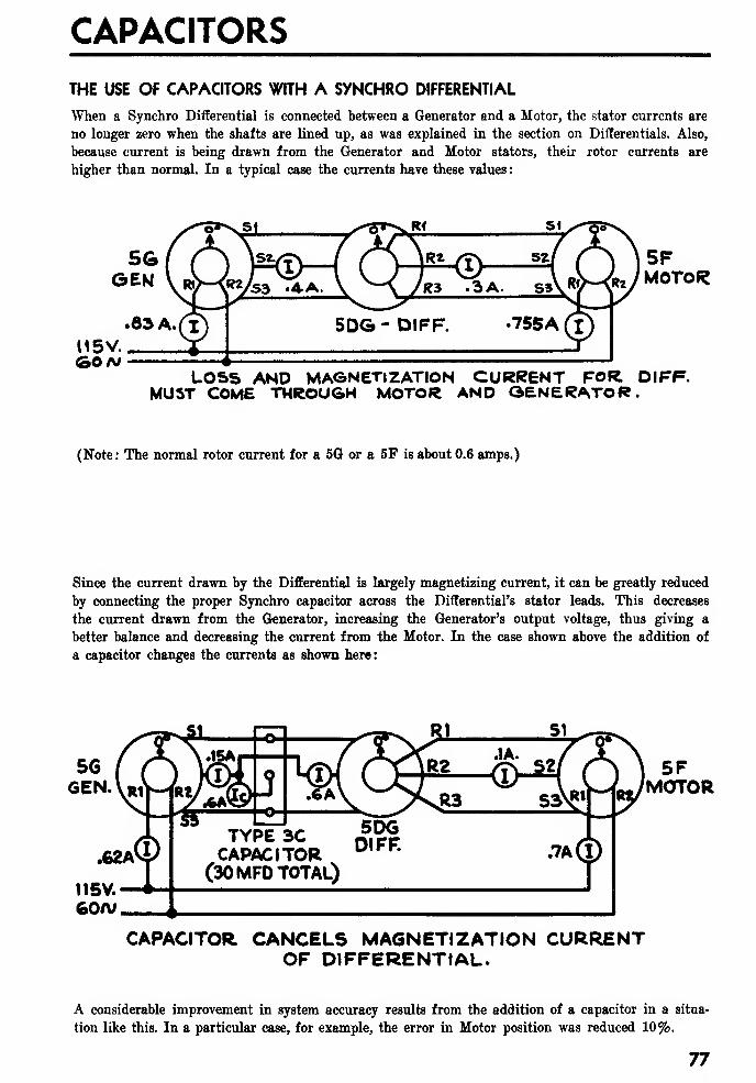
CAPACITORS
THE USE OF CAPACITORS WITH A SYNCHRO DIFFERENTIAL
^Tien a Synchro Differential is connected between a Generator and a Motor, the stator currents are
no longer zero when the shafts are lined up, as was explained in the section on Differentials. Also,
because current is being drawn from the Generator and Motor stators, their rotor currents are
higher than normal. In a typical case the currents have these values
:
115V.<30/v
LOSS AND MAGNETIZATION CURRENT FOR DIFF.MUST COME THROUGH MOTOR AND GENERATOR.
(Note: The normal rotor current for a 5G or a 5F is about 0.6 amps.)
Since the current drawn by the Differential is largely magnetizing current, it can be greatly reduced
by connecting the proper Synchro capacitor across the Differential's stator leads. This decreases
the current drawn from the Generator, increasing the Generator's output voltage, thus giving a
better balance and decreasing the current from the Motor. In the case shown above the addition of
a capacitor changes the currents as shown here:
.62A
115V.60A/,
.CDTYPE 3CCAPACITOR
(30 MFD TOTAL)
5D6DIFF. .7AO)
5FMOTOR
CAPACITOR CANCELS MAGNETIZATION CURRENTOF DIFFERENTIAL.
A considerable improvement in system accuracy results from the addition of a capacitor in a situa-
tion like this. In a particular case, for example, the error in Motor position was reduced 10%.
77
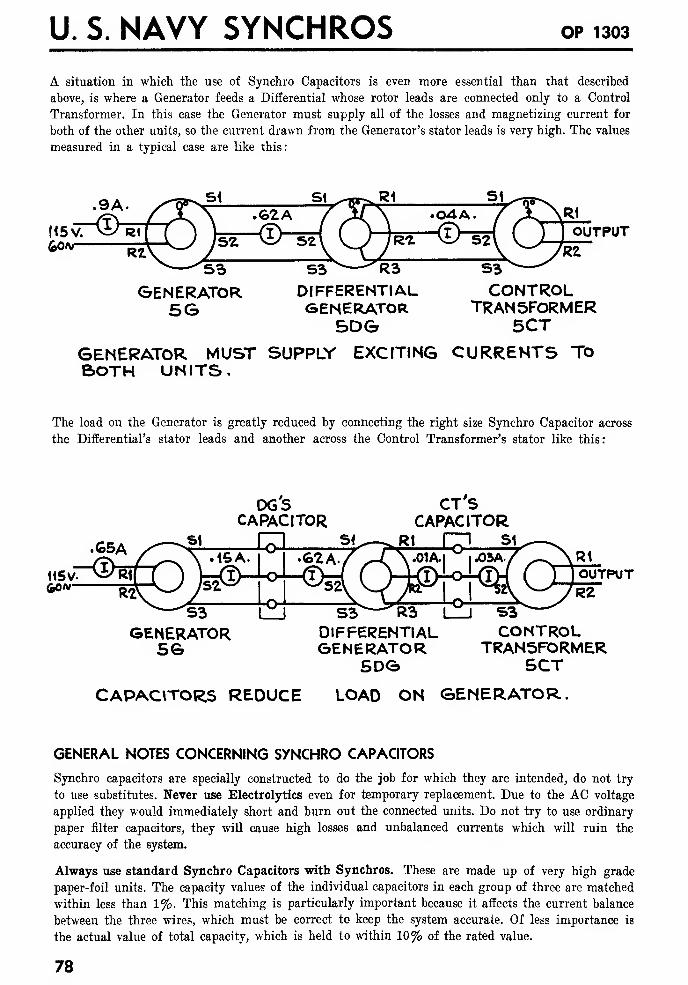
U. S. NAVY SYNCHROS OP 1303
A situation in which the use of Synchro Capacitors is even more essential than that described
above, is where a Generator feeds a Differential whose rotor leads are connected only to a Control
Transformer. In this case the Generator must supply all of the losses and magnetizing current for
both of the other units, so the current drawn from the Generator's stator leads is very high. The values
measured in a typical case are like this:
OUTPUT60/v
S3GENERATOR
5G
S3 R3DIFFERENTIALGENERATOR
5DG
S3
CONTROLTRANSFORMER
5CT
GENERATOR MUST SUPPLY EXCITING CURRENTS ToBOTH UNITS.
The load on the Generator is greatly reduced by connecting the right size Synchro Capacitor across
the Differential's stator leads and another across the Control Transformer's stator like this:
DGSCAPACITOR
•C5A
U5v~~®Ri60a;
S3GENERATOR
5G
CTSCAPACITOR
Rt m si
S3 R3DIFFERENTIALGENERATOR
SDG
OUTPUT
S3^CONTROL
TRANSFORMERSCT
CAPACITORS REDUCE LOAD ON GENERATOR.
GENERAL NOTES CONCERNING SYNCHRO CAPACITORS
Synchro capacitors are specially constructed to do the job for which they are intended, do not try
to use substitutes. Never use Electrolytics even for temporary replacement. Due to the AC voltage
applied they would immediately short and burn out the connected units. Do not try to use ordinary
paper filter capacitors, they will cause high losses and unbalanced currents which will ruin the
accuracy of the system.
Always use standard Synchro Capacitors with Synchros. These are made up of very high grade
paper-foil units. The capacity values of the individual capacitors in each group of three are matched
within less than 1%. This matching is particularly important because it affects the current balance
between the three wires, which must be correct to keep the system accurate. Of less importance is
the actual value of total capacity, which is held to within 10% of the rated value.
78
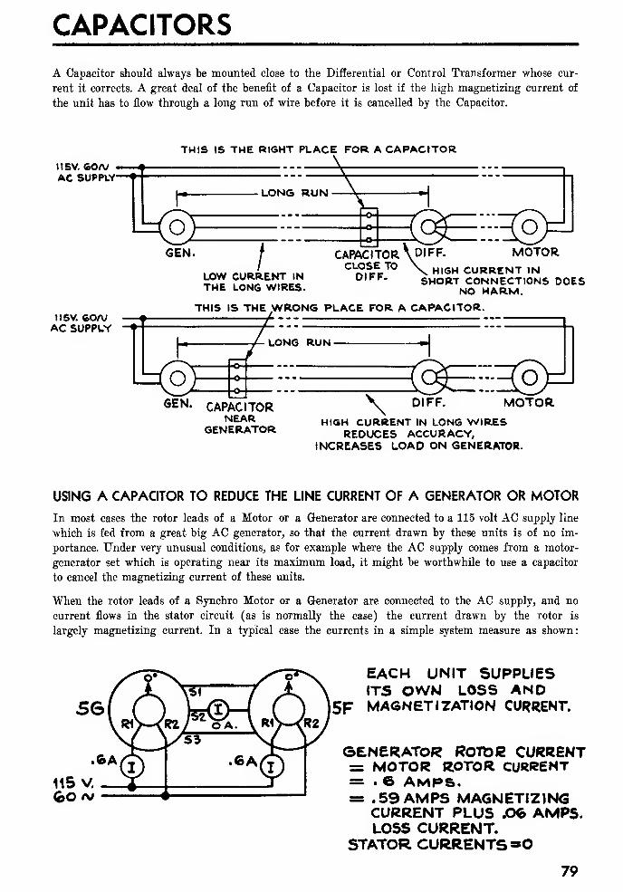
CAPACITORS
A Capacitor should always be mounted close to the Differential or Control Transformer whose cur-
rent it corrects. A great deal of the benefit of a Capacitor is lost if the high magnetizing current of
the unit has to flow through a long run of wire before it is cancelled by the Capacitor.
THIS IS THE RIGHT PLACE FOR A CAPACITORI1SV. 60A/ -
AC SUPPLY-
LONG RUN
oGEN.
/LOW CURRENT INTHE LONG WIRES.
CAPACITORCLOSE TODIFF.
DIFF. MOTORHIGH CURRENT IN
SHORT CONNECTIONS DOESNO HARM.
115V. feOAVAC SUPPLY
THIS IS THE WRONG PLACE FOR A CAPACITOR.
LONG RUN-
CAPAC TORNEAR
GENERATOR
\o
DIFF. MOTORHIGH CURRENT IN LONG WIRES
REDUCES ACCURACY,INCREASES LOAD ON GENERATOR.
USING A CAPACITOR TO REDUCE THE LINE CURRENT OF A GENERATOR OR MOTOR
In most cases the rotor leads of a Motor or a Generator are connected to a 115 volt AC supply line
which is fed from a great big AC generator, so that the current drawn by these units is of no im-
portance. Under very unusual conditions, as for example where the AC supply comes from a motor-
generator set which is operating near its maximum load, it might be worthwhile to use a capacitor
to cancel the magnetizing current of these units.
When the rotor leads of a Synchro Motor or a Generator are connected to the AC supply, and no
current flows in the stator circuit (as is normally the case) the current drawn by the rotor is
largely magnetizing current. In a typical case the currents in a simple system measure as shown:
EACH UNIT SUPPLIESITS OWN LOSS AND
5F MAGNETIZATION CURRENT.
GENERATOR ROTIDC CURRENT= MOTOR ROTOR CURRENT= . 6 amps.= .59 AMPS MAGNETIZING
CURRENT PLUS JOG AMPS.LOSS CURRENT.
STATOR CURRENTS«0
79
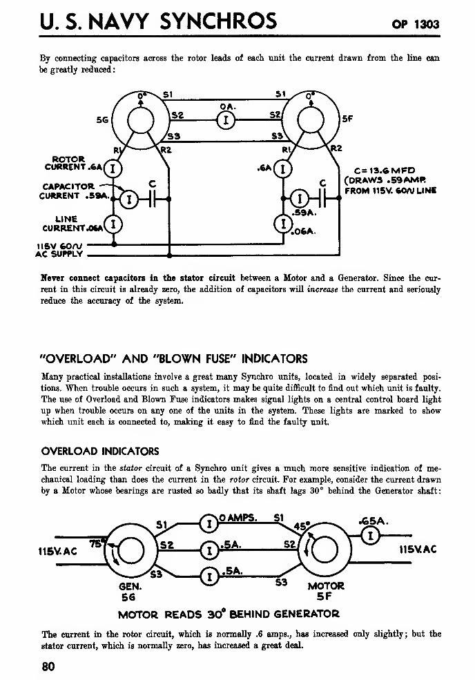
U. S. NAVY SYNCHROS OP 1303
By connecting capacitors across the rotor leads of each unit the current drawn from the line can
be greatly reduced
:
ROTORCURRENT .6A
CAPACITORCURRENT .59A.
LINECURRENT .OftA
IISV 60<VAC SUPPLY
C= 13.6MFD(DRAWS .59AMRFROM 115V. 60A/ LINE
Never connect capacitors in the stator circuit between a Motor and a Generator. Since the cur-
rent in this circuit is already zero, the addition of capacitors will increase the current and seriously
reduce the accuracy of the system.
"OVERLOAD" AND "BLOWN FUSE" INDICATORS
Many practical installations involve a great many Synchro units, located in widely separated posi-
tions. When trouble occurs in such a system, it may be quite difficult to find out which unit is faulty.
The use of Overload and Blown Fuse indicators makes signal lights on a central control board light
up when trouble occurs on any one of the units in the system. These lights are marked to show
which unit each is connected to, making it easy to find the faulty unit.
OVERLOAD INDICATORS
The current in the stator circuit of a Synchro unit gives a much more sensitive indication of me-
chanical loading than does the current in the rotor circuit. For example, consider the current drawn
by a Motor whose bearings are rusted so badly that its shaft lags 30° behind the Generator shaft:
.65A.
115V AC 115V.AC
MOTOR READS 30° BEHIND GENERATOR
The current in the rotor circuit, which is normally .6 amps., has increased only slightly; but the
stator current, which is normally zero, has increased a great deal.
80
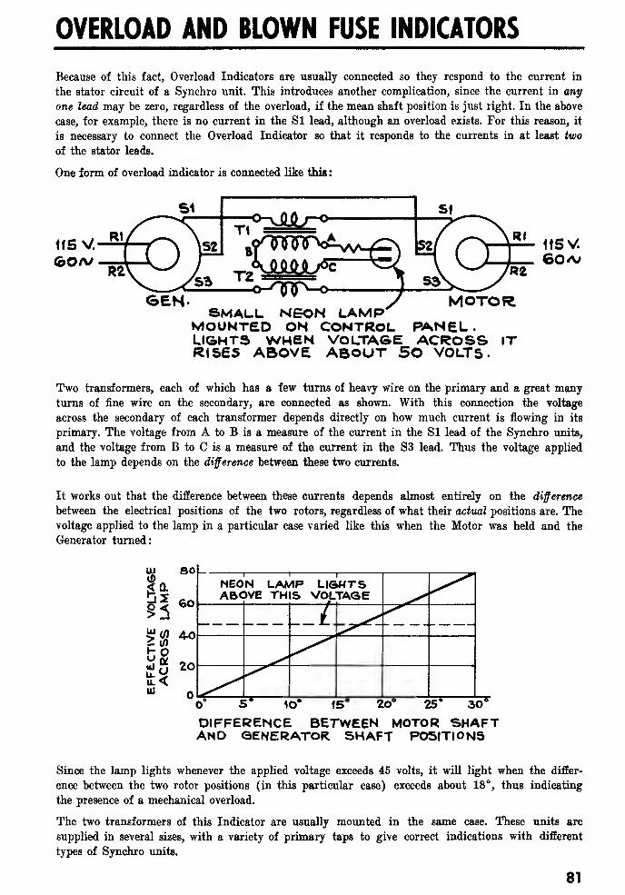
OVERLOAD AND BLOWN FUSE INDICATORS
Because of this fact, Overload Indicators are usually connected so they respond to the current in
the stator circuit of a Synchro unit. This introduces another complication, since the current in any
one lead may be zero, regardless of the overload, if the mean shaft position is just right. In the above
case, for example, there is no current in the Si lead, although an overload exists. For this reason, it
is necessary to connect the Overload Indicator so that it responds to the currents in at least two
of the stator leads.
One form of overload indicator is connected like this
:
SEN- '
'
y MOTORSMALL NEON LAMP
MOUNTED ON CONTROL PANEL.LIGHTS WHEN VOLTAGE ACROSS ITRISES ABOVE ABOUT 50 VOLTS.
Two transformers, each of which has a few turns of heavy wire on the primary and a great manyturns of fine wire on the secondary, are connected as shown. With this connection the voltage
across the secondary of each transformer depends directly on how much current is flowing in its
primary. The voltage from A to B is a measure of the current in the SI lead of the Synchro units,
and the voltage from B to C is a measure of the current in the S3 lead. Thus the voltage applied
to the lamp depends on the difference between these two currents.
It works out that the difference between these currents depends almost entirely on the difference
between the electrical positions of the two rotors, regardless of what their actual positions are. Thevoltage applied to the lamp in a particular case varied like this when the Motor was held and the
Generator turned:
lO5 iP 20s 25* 30*"
DIFFERENCE BETWEEN MOTOR SHAFTAND GENERATOR SHAFT POSITIONS
Since the lamp lights whenever the applied voltage exceeds 45 volts, it will light when the differ-
ence between the two rotor positions (in this particular case) exceeds about 18°, thus indicating
the presence of a mechanical overload.
The two transformers of this Indicator are usually mounted in the same case. These units are
supplied in several sizes, with a variety of primary taps to give correct indications with different
types of Synchro units.
81

U. S. NAVY SYNCHROS OP 1303
BLOWN FUSE INDICATORS
In addition to the Overload Indicators described above, it is customary to protect a Synchro Motor
or Generator with fuses connected like this:
ffSV
SUPPLY
-cf\j>
<r\jo
SYNCHRO MOTOROR GENERATOR
These fuses are the right size so that they will blow out and open the circuit if excessive current
flows in the rotor circuit due to a short in the windings or a severe mechanical overload. When this
happens, the Overload Indicator may not give any indication of trouble, since the rotor circuit is
no longer excited, and a second type of indicator is needed which lights up when a fuse blows out.
A simple type of Blown Fuse Indicator is obtained by simply connecting small neon lamps across
the fuses like this:
NEONLAMPS SYNCHRO
St
115V60/VAC SUPPLY
If either fuse blows, the voltage that appears across it will light the corresponding lamp, giving in-
dication of the failure.
One disadvantage of this simple type of Blown Fuse Indicator is that the leads that connect to the
lamps on the central panel (which may be some distance away from the Synchro) are connected
directly across the rotor. Any short circuit in these leads will put the Synchro out of commission.
Another type of Blown Fuse Indicator that gets away from this trouble, is connected like this:
<f\/>
115 V.
SUPPLY
SYNCHRO
-
MOTOR, ORGENERATOR
NEON* LAMPLIGHTS WHEN APPLIED VOLTAGEEXCEEDS ABOUT SO VOLTS.
82
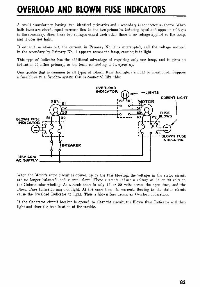
OVERLOAD AND BLOWN FUSE INDICATORS
A small transformer having two identical primaries and a secondary is connected as shown. Whenboth fuses are closed, equal currents flow in the two primaries, inducing equal and opposite voltages
in the secondary. Since these two voltages cancel each other there is no voltage applied to the lamp,
and it does not light.
If either fuse blows out, the current in Primary No. 2 is interrupted, and the voltage induced
in the secondary by Primary No. 1 appears across the lamp, causing it to light.
This type of indicator has the additional advantage of requiring only one lamp, and it gives an
indication if either primary, or the leads connecting to it, opens up.
One trouble that is common to all types of Blown Fuse Indicators should be mentioned. Suppose
a fuse blows in a Synchro system that is connected like this:
GEN.
BLOWN FUSEINDICATOR «~:
115V GOrt/AC SUPPLY
OVERLOADINDICATOR LIGHTS
BREAKER
OTORDOESNT LIGHT
FUSER2 BLOWS
4©'-J BLOWN FUSE
INDICATOR
When the Motor's rotor circuit is opened up by the fuse blowing, the voltages in the stator circuit
are no longer balanced, and current flows. These currents induce a voltage of 85 or 90 volts in
the Motor's rotor winding. As a result there is only 15 or 20 volts across the open fuse, and the
Blown Fuse Indicator may not light. At the same time the currents flowing in the stator circuit
cause the Overload Indicator to light. Thus a blown fuse causes an Overload indication.
If the Generator circuit breaker is opened to clear the circuit, the Blown Fuse Indicator will then
light and show the true location of the trouble.
83

U. S. NAVY SYNCHROS op 1303
84
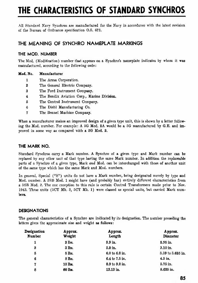
THE CHARACTERISTICS OF STANDARD SYNCHROS
All Standard Navy Synchros are manufactured for the Navy in accordance with the latest revision
of the Bureau of Ordnance specification O.S. 671.
THE MEANING OF SYNCHRO NAMEPLATE MARKINGS
THE MOD. NUMBER
The Mod. (Modification) number that appears on a Synchro's nameplate indicates by whom it was
manufactured, according to the following code:
Mod. No. Manufacturer
1 The Arma Corporation.
2 The General Electric Company.
3 The Ford Instrument Company.
4 The Bendix Aviation Corp., Marine Division.
5 The Control Instrument Company.
6 The Diehl Manufacturing Co.
7 The Bennel Machine Company.
When a manufacturer makes an improved design of a given type unit, this is shown by a letter follow-
ing the Mod. number. For example : A 5G Mod. 2A would be a 5G manufactured by G.E. and im-
proved in some way as compared with a 5G Mod. 2.
THE MARK NO.
Standard Synchros carry a Mark number. A Synchro of a given type and Mark number can be
replaced by any other unit of that type having the same Mark number. In addition the replaceable
parts of a Synchro of a given type, Mark and Mod. can be interchanged with those of another unit
of the same type which has the same Mark and Mod. numbers.
In general, Special ("S") units do not have a Mark number, being designated merely by type and
Mod. number. A 5SB Mod. 1 might have (and probably has) entirely different characteristics from
a 5SB Mod. 2. The one exception to this rule is certain Control Transformers made prior to Nov.
1943. These units (5CT Mk. 3, 5CT Mk. 1) were classed as special units, but carried Mark num-
bers.
DESIGNATIONS
The general characteristics of a Synchro are indicated by its designation. The number preceding the
letters gives the approximate size and weight as follows:
Approx.
Diameter
2.95 in.
3.10 in.
3.39 to 3.625 in.
4.5 in.
5.75 in.
8.625 in.
85
Designation
Number
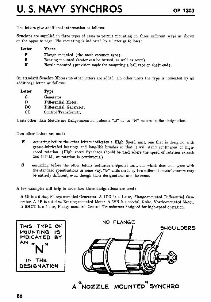
U. S. NAVY SYNCHROS OP 1303
The letters give additional information as follows
:
Synchros are supplied in three types of cases to permit mounting in three different ways as shown
on the opposite page. The mounting is indicated by a letter as follows
:
Letter Means
F Flange mounted (the most common type).
B Bearing mounted (stator can be turned, as well as rotor).
N Nozzle mounted (provision made for mounting a ball race on shaft end).
On standard Synchro Motors no other letters are added. On other units the type is indicated by an
additional letter as follows:
Letter
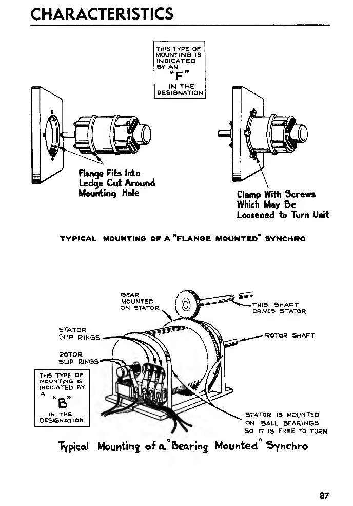
CHARACTERISTICS
THIS TYPE OFMOUNTING ISINDICATEDBY AN
IN THEDESIGNATION
Flange Fits Into
Ledge Cut AroundMounting Hole Clamp With Screws
Which May BeLoosened to Turn Unit
TYPICAL MOUNTING OFA'VlANGE MOUNTED* SYNCHRO
SEARMOUNTEDON STATOR
STATORSLIP RINGS
ROTORSLIP RINGS - -iS\
THIS TYPE OFMOUNTING IS
INDICATED BYA « _ »
BIN THE
DESIGNATION
THIS SHAFTDRIVES STATOR
ROTOR SHAFT
STATOR IS MOUNTEDON BALL BEARINGSSO IT IS FREE TO TURN
Typical Mounting of a bearing Mounted Synchro
87
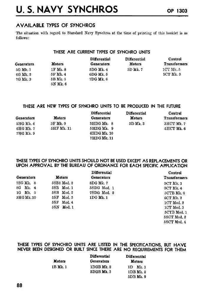
U. S. NAVY SYNCHROS OP 1303
AVAILABLE TYPES OF SYNCHROS
The situation with regard to Standard Navy Synchros at the time of printing of this booklet is as
follows
:
THESE ARE CURRENT TYPES OF SYNCHRO UNITS
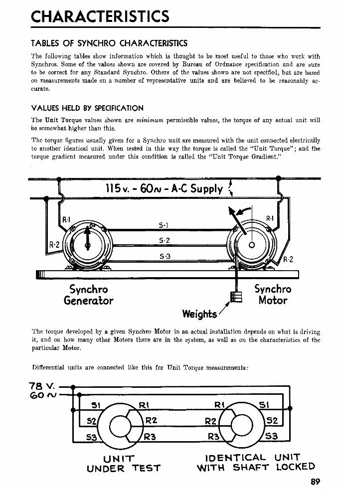
CHARACTERISTICS
TABLES OF SYNCHRO CHARACTERISTICS
The following tables show information which is thought to be most useful to those who work with
Synchros. Some of the values shown are covered by Bureau of Ordnance specification and are sure
to be correct for any Standard Synchro. Others of the values shown are not specified, but are based
on measurements made on a number of representative units and are believed to be reasonably ac-
curate.
VALUES HELD BY SPECIFICATION
The Unit Torque values shown are minimum permissible values, the torque of any actual unit will
be somewhat higher than this.
The torque figures usually given for a Synchro unit are measured with the unit connected electrically
to another identical unit. When tested in this way the torque is called the "Unit Torque"; and the
torque gradient measured under this condition is called the "Unit Torque Gradient."
115v.-60aj-A-C Supply {
s-i
S-2
S-3
SynchroGenerator
Weights/Synchro
Motor
The torque developed by a given Synchro Motor in an actual installation depends on what is driving
it, and on how many other Motors there are in the system, as well as on the characteristics of the
particular Motor.
Differential units are connected like this for Unit Torque measurements:
78 V. —
+
GO *v
UNI"UNDER TEST
IDENTICAL UNITWITH SHAFT LOCKED
89
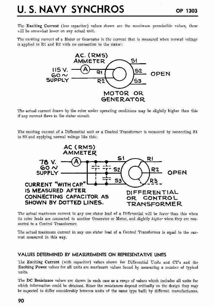
U. S. NAVY SYNCHROS op 1303
The Exciting Current (less capacitor) values shown are the maximum permissible values, these
will be somewhat lower on any actual unit.
The exciting current of a Motor or Generator is the current that is measured when normal voltage
is applied to El and E2 with no connection to the stator:
AC. (RMS)AMMETER
GO~ ^" *M ( J p1" OPENSUPPLY
MOTOR ORGENERATOR
The actual current drawn by the rotor under operating conditions may be slightly higher than this
if any current flows in the stator circuit.
The exciting current of a Differential unit or a Control Transformer is measured by connecting Si
to S3 and applying normal voltage like this:
AC (RMS)AMMETER
78 V. © ft*SUPPLY 1—
I
t-^M ( ) P fc OPEN
CURRENT "WITH CAR"IS MEASURED AFTER DIFFERENTIALCONNECTING CAPACITOR AS QR CONTROL.SHOWN BY DOTTED LINES. TRANSFORMER
The actual maximum current in any one stator lead of a Differential will be lower than this when
its rotor leads are connected to another Generator or Motor, and slightly higher when they are con-
nected to a Control Transformer.
The actual maximum current in any one stator lead of a Control Transformer is equal to the cur-
rent measured in this way.
VALUES DETERMINED BY MEASUREMENTS ON REPRESENTATIVE UNITS
The Exciting Current (with capacitor) values shown for Differential Units and CT's and the
Exciting Power values for all units are maximum values found by measuring a number of typical
units.
The DC Resistance values are shown in each case as a range of values which includes all units for
which information could be obtained. Since the resistances depend critically on the design they maybe expected to differ considerably between units of the same type built by different manufacturers.
90
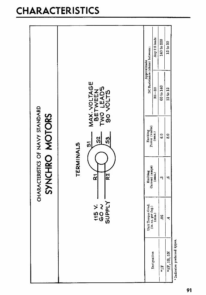
CHARACTERISTICS
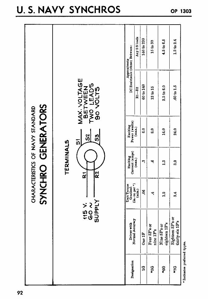
U. S. NAVY SYNCHROS OP 1303
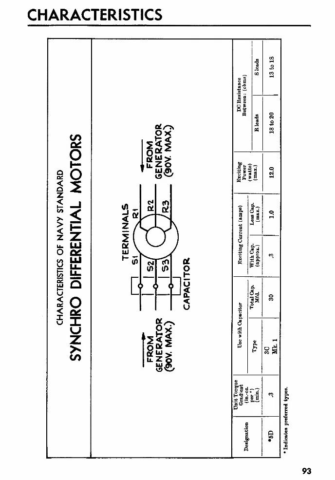
CHARACTERISTICS
!
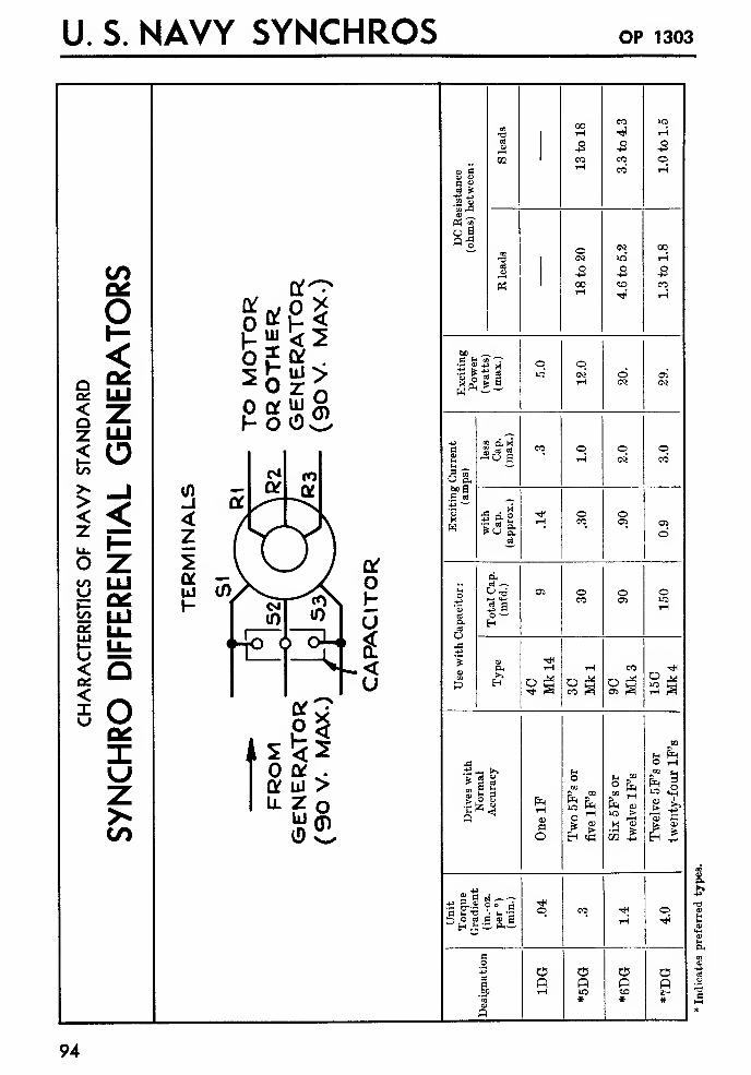
U. S. NAVY SYNCHROS OP 1303

CHARACTERISTICS
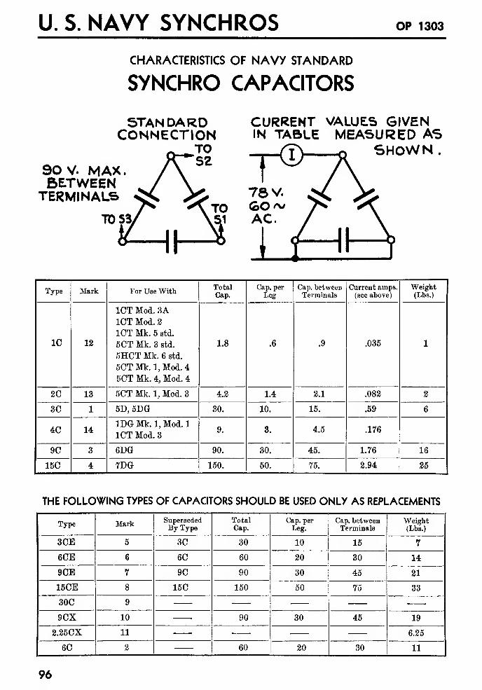
U. S. NAVY SYNCHROS OP 1303
CHARACTERISTICS OF NAVY STANDARD
SYNCHRO CAPACITORS
90 V. MAX.BETWEENTERMINALS
STANDARDCONNECTION
TO/\ SZ
CURRENT VALUES GIVENIN TABLE MEASURED AS
SHOWN
TO
nType
CHARACTERISTICS
SYNCHRO CAPACITOR BOXES
It is a necessary requirement that a Synchro Capacitor should be mounted as close as is practical to
the unit whose current it corrects. In some cases this means that the Capacitor must be mounted in
an exposed location. Capacitor boxes are designed to protect the Capacitor in such a case.
STANDARD CAPACITOR BOXES
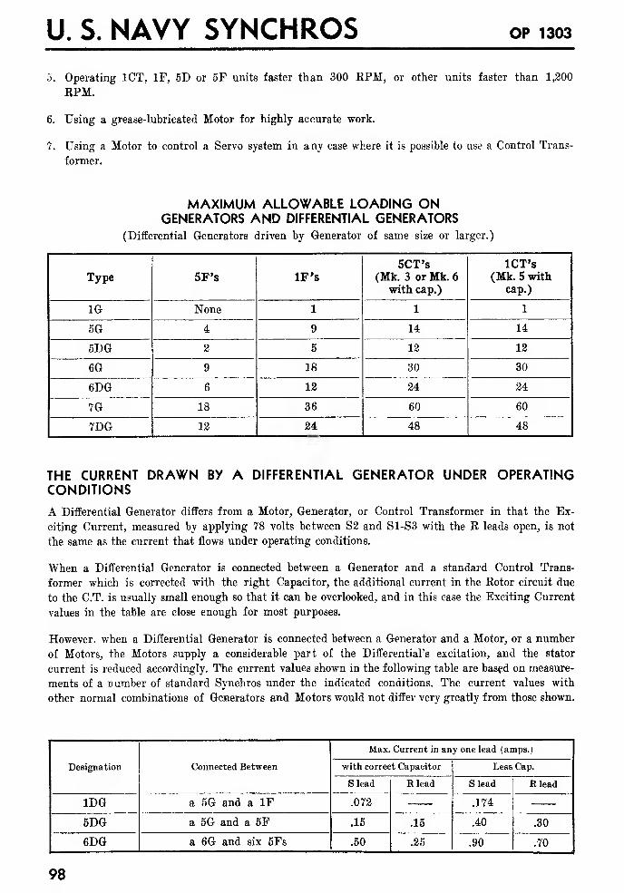
U. S. NAVY SYNCHROS OP 1303
5. Operating 1CT, IF, 5D or 5F units faster than 300 KPM, or other units faster than 1,200
KPM.
6. Using a grease-lubricated Motor for highly accurate work.
7. Using a Motor to control a Servo system in any case where it is possible to use a Control Trans-
former.
MAXIMUM ALLOWABLE LOADING ONGENERATORS AND DIFFERENTIAL GENERATORS
(Differential Generators driven by Generator of same size or larger.)
Type
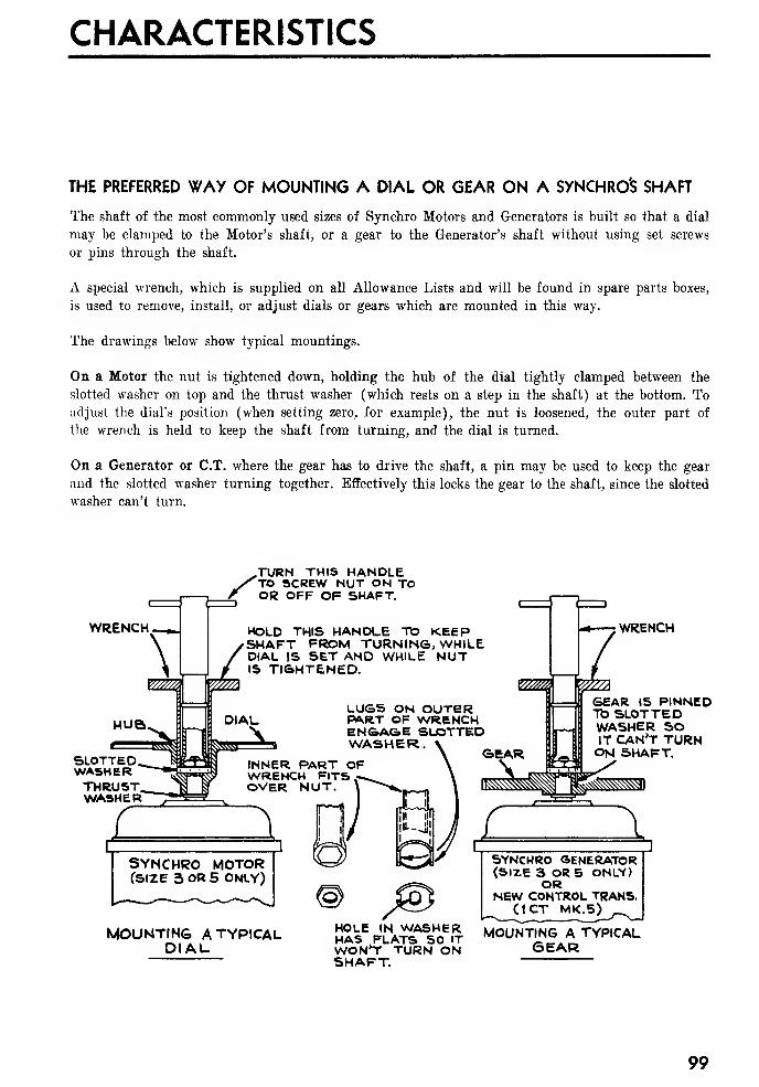
CHARACTERISTICS
THE PREFERRED WAY OF MOUNTING A DIAL OR GEAR ON A SYNCHROS SHAFT
The shaft of the most commonly used sizes of Synchro Motors and Generators is built so that a dial
may be clamped to the Motor's shaft, or a gear to the Generator's shaft without using set screws
or pins through the shaft.
A special wrench, which is supplied on all Allowance Lists and will be found in spare parts boxes,
is used to remove, install, or adjust dials or gears which are mounted in this way.
The drawings below show typical mountings.
On a Motor the nut is tightened down, holding the hub of the dial tightly clamped between the
slotted washer on top and the thrust washer (which rests on a step in the shaft) at the bottom. Toadjust the dial's position (when setting zero, for example), the nut is loosened, the outer part of
the wrench is held to keep the shaft from turning, and the dial is turned.
On a Generator or C.T. where the gear has to drive the shaft, a pin may be used to keep the gear
and the slotted washer turning together. Effectively this locks the gear to the shaft, since the slotted
washer can't turn.
/WRENCH
SLOTTEDWASHERTHRUST,WASHER
TURN THIS HANDLETO SCREW NUT ON TOOR OFF OF SHAFT.
<==$ X
HOLD THIS HANDLE TO KEEPSHAFT FROM TURN INS, WHILEDIAL IS SET AND WHILE NUTIS TI&HTENED.
LUGS ON OUTERPART OF WRENCHEN&A&E SLOTTEDWASHER.
INNER PART OFWRENCH FITSOVER NUT.
£ 1SYNCHRO MOTORCSIZE 3 OR 5 ONLY)
MOUNTING ATYPICALDIAL.
©CAR
; WRENCH
GEAR IS PINNEDTO SLOTTEDWASHER SOIT CAN'T TURNON SHAFT.
HOLE IN WASHERHAS FLATS SO ITWON'T TURN ONSHAFT.
SYNCHRO GENERATOR(SIZE 3 OR 5 ONLY)
ORNEW CONTROL TRANS.
(1CT ****'),--.
MOUNTING A TYPICALSEAR
99
U. S. NAVY SYNCHROS op 1303
100
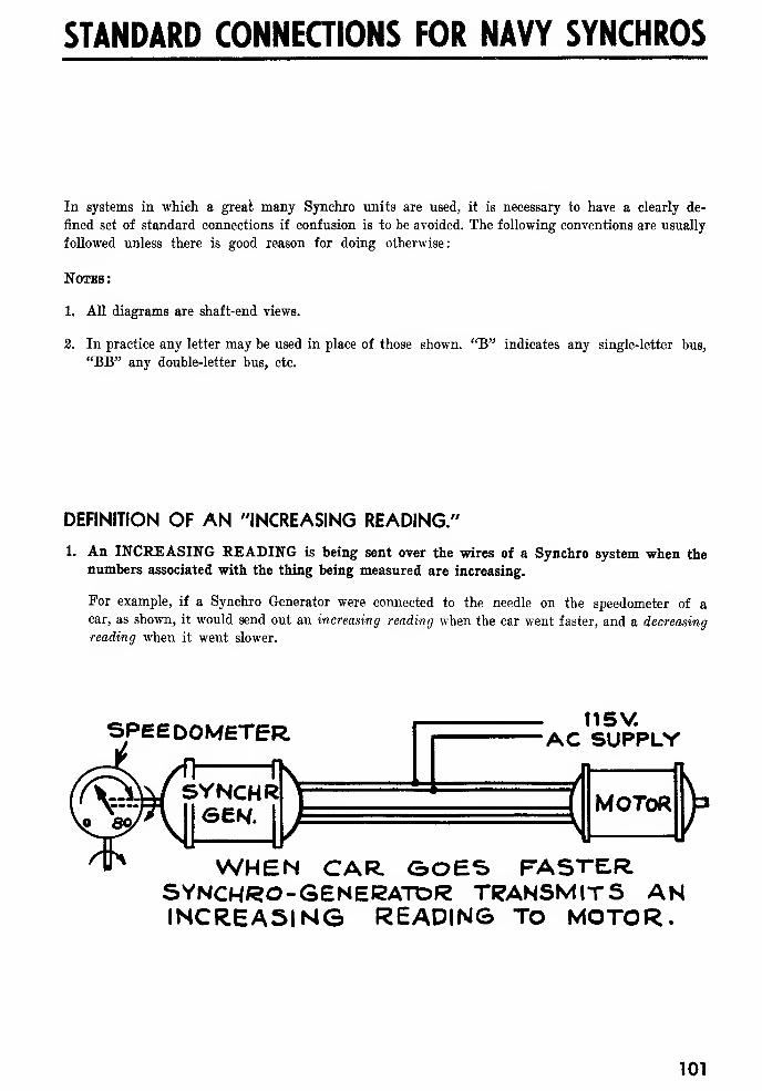
STANDARD CONNECTIONS FOR NAVY SYNCHROS
In systems in which a great many Synchro units are used, it is necessary to have a clearly de-
fined set of standard connections if confusion is to be avoided. The following conventions are usually
followed unless there is good reason for doing otherwise:
Notes :
1. All diagrams are shaft-end views.
2. In practice any letter may be used in place of those shown. "B" indicates any single-letter bus,
"BB" any double-letter bus, etc.
DEFINITION OF AN "INCREASING READING."
1. An INCREASING READING is being sent over the wires of a Synchro system when thenumbers associated with the thing being measured are increasing.
For example, if a Synchro Generator were connected to the needle on the speedometer of acar, as shown, it would send out an increasing reading when the ear went faster, and a decreasing
reading when it went slower.
SPEEDOMETER t15V.AC SUPPLY
f MOTOR P
WHEN CAR GOES FASTERSYNCHRO-GENERATOR TRANSMITS ANINCREASING READING TO MOTOR.
101
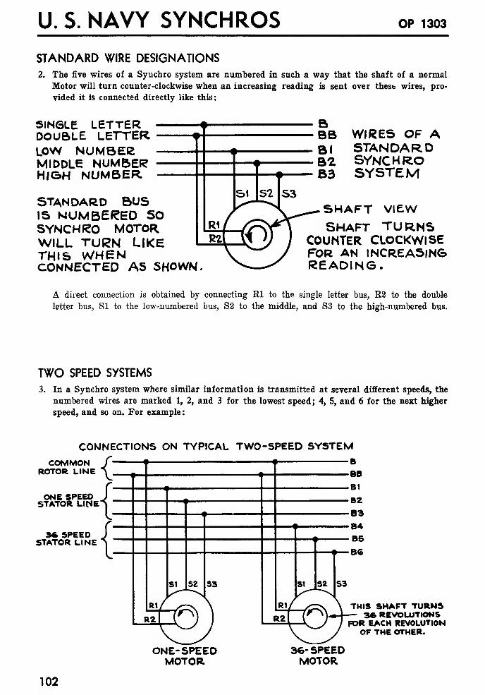
U. S. NAVY SYNCHROS OP 1303
STANDARD WIRE DESIGNATIONS2. The five wires of a Synchro system are numbered in such a way that the shaft of a normal
Motor will turn counter-clockwise when an increasing reading is sent over thest wires, pro-
vided it is connected directly like this:
SINGLE LETTERDOUBLE LETTERLOW NUMBEfcMIDDLE NUMBERHIGH NUMBER
STANDARD BUSIS NUMBERED SOSYNCHRO MOTORWILL TURN LIKETHIS WHENCONNECTED AS SHOWN.
WIRES OF ASTANDARDSYNCHROSYSTEM
SHAFT VIEW
SHAFT TURNSCOUNTER CLOCKWISEFOR AN INCREASINGREADING.
A direct connection is obtained by connecting Rl to the single letter bus, R2 to the double
letter bus, SI to the low-numbered bus, S2 to the middle, and S3 to the high-numbered bus.
TWO SPEED SYSTEMS
3. In a Synchro system where similar information is transmitted at several different speeds, the
numbered wires are marked 1, 2, and 3 for the lowest speed; 4, 5, and 6 for the next higher
speed, and so on. For example :
COMMONROTOR LINE
CONNECTIONS ON TYPICAL TWO-SPEED SYSTEMB
BB
B1
{=3ONE SPEED .
STATOR LIME
36 SPEEDSTATOR LINE
THIS SHAFT TURNS3* REVOLUTIONS
FOR EACH REVOLUTIONOF THE OTHER.
ONE-SPEEDMOTOR.
36- SPEEDMOTOR
102
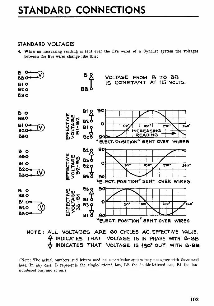
STANDARD CONNECTIONS
STANDARD VOLTAGES4. When an increasing reading is sent over the five wires of a Synchro system the voltages
between the five wires change like this:
BBO-«—
^
BIOBZOB30
BBO
VOLTAGE FROM B TO BBIS CONSTANT AT 115 VOLTS.
B OBBO
BZO*—*o/
B30
B OBBOB1 O
B OBBOB1
B20B30
* ELECT. POSITION " SENT OVER WIRES
uj Lidu-Otfl
Up i
u;>UJ
B2 SO
BaT
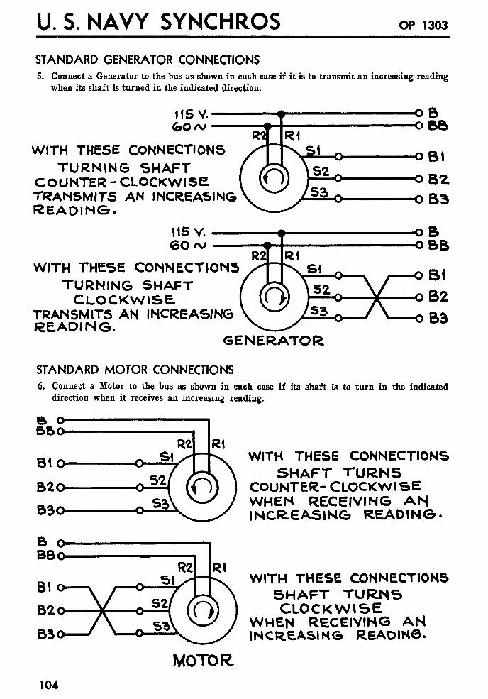
U. S. NAVY SYNCHROS OP 1303
STANDARD GENERATOR CONNECTIONS5. Connect a Generator to the bus as shown in each case if it is to transmit an increasing reading
when its shaft is turned in the indicated direction.
II5V.fcO/v
WITH THESE CONNECTIONSTURNING SHAFT
COUNTER - CLOCKWISETRANSMITS AN INCREASINGREADING.
OBOBB
OB2OB3
115 V.
60>\>
WITH THESE CONNECTIONSTURNING SHAFTCLOCKWISE
TRANSMITS AN INCREAS/NGREADING.
GENERATOR
STANDARD MOTOR CONNECTIONS6. Connect a Motor to the bus as shown in each case if its shaft is to turn in the indicated
direction when it receives an increasing reading.
bbo
BIO
B20
B30
B ©BBo-
WITH THESE CONNECTIONSSHAFT TURNS
COUNTER- CLOCKWISEWHEN RECEIVING ANINCREASING READING-
WITH THESE CONNECTIONSSHAFT TURNSCLOCKWISE
WHEN RECEIVING ANINCREASING READING.
MOTOR.
104
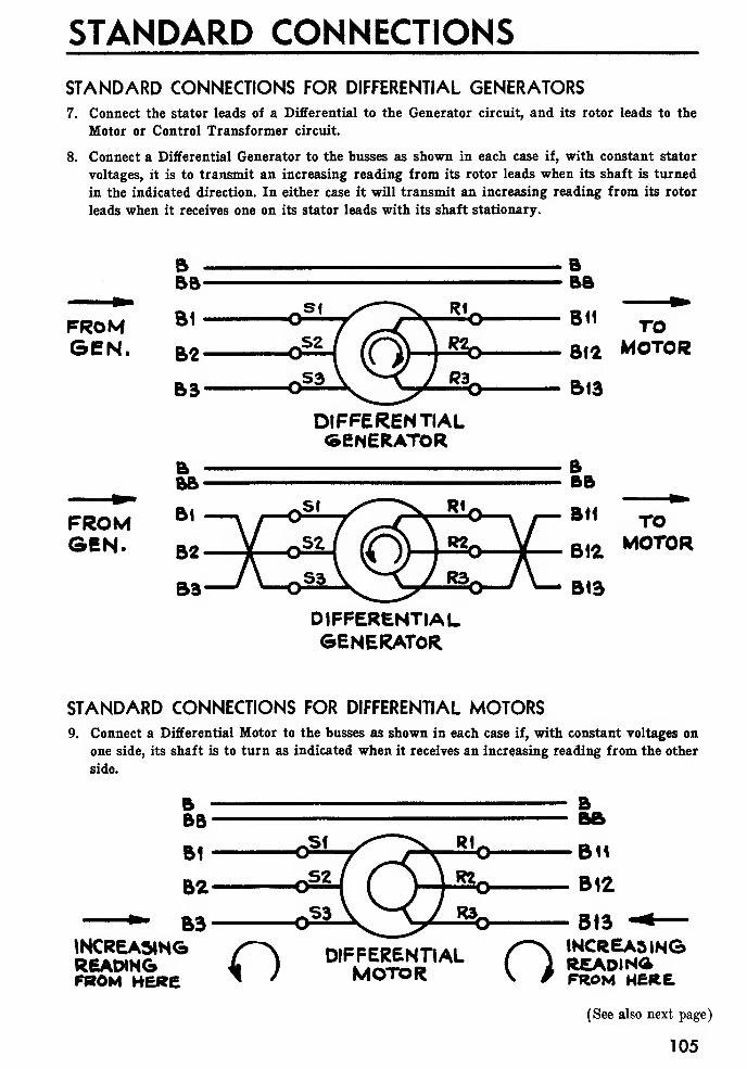
STANDARD CONNECTIONS
STANDARD CONNECTIONS FOR DIFFERENTIAL GENERATORS7. Connect the stator leads of a Differential to the Generator circuit, and its rotor leads to the
Motor or Control Transformer circuit.
8. Connect a Differential Generator to the busses as shown in each case if, with constant stator
voltages, it is to transmit an increasing reading from its rotor leads when its shaft is turned
in the indicated direction. In either case it will transmit an increasing reading from its rotor
leads when it receives one on its stator leads with its shaft stationary.
FROMGEN.
DIFFERENTIALGENERATOR
FROMGEN.
BBB
B« TO
BWL MOTOR
B13
DIFFERENTIALGENERATOR
STANDARD CONNECTIONS FOR DIFFERENTIAL MOTORS9. Connect a Differential Motor to the busses as shown in each case if, with constant voltages on
one side, its shaft is to turn as indicated when it receives an increasing reading from the other
side.
B3INCREASINGREADINGFROM HERE o DIFFERENTIAL
MOTOR o INCREASINGREADINGFROM HERE
(See also next page)
105
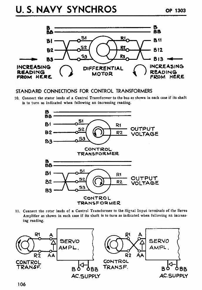
U. S. NAVY SYNCHROS OP 1303
INCREASINGREADINGPROM HERE. o DIFFERENTIAL
MOTOR o INCREASINGREADINGFROM HERE
STANDARD CONNECTIONS FOR CONTROL TRANSFORMERS
10. Connect the stator leads of a Control Transformer to the bus as shown in each case if its shaft
is to turn as indicated when following an increasing reading.
OUTPUTVOLTAGE
CONTROLTRANSFORMER.
OUTPUTVOLTAGE
CONTROLTRANSFORMER
11. Connect the rotor leads of a Control Transformer to the Signal Input terminals of the Servo
Amplifier as shown in each case if its shaft is to turn as indicated when following an increas-
ing reading.
^^ R2 AACONTROLTRANSF. M R2 AA
CONTROL
SERVOAMPL.
BO' OBB T*ANSF.
AC.5UPPLY
,6 6iBO OBBACSUPPLY
106

STANDARD CONNECTIONS
STANDARD CONNECTIONS FOR SYNCHRO CAPACITORS
12. Whenever a Differential or Control Transformer is used, mount a Synchro Capacitor of the
proper size as close to it as possible, and connect as shown below
:
SUPPLY R2
<15V.GO AJ
SUPPLY
GEN. CAPACITORFOR C.T.
CONTROLTRANSF".
GEN. CAPACITORFOR DIFF.
DIFF.MOTOR ORGENERATOR
MOTOR.OR.
GENERATOR
115V.GO <v
SUPPLY
GEN. CARFOR DIFF.
DIFF. CAP CONTROLFOR TRANSFORMER
GENERATOR c.T.
STANDARD CONNECTIONS FOR SERVO AMPLIFIERS
13. When a Servo System is following an increasing reading, the Signal Input voltage is in phase
with the AC Supply voltage, and the Output voltage is either positive (for a DC output),
in phase with the supply (for a straight AC amplifier), or lags the supply by 90° (when there
is a 90° shift in the amplifier). (In each case the voltage is measured at the single-letter
terminal on the Servo Amplifier with respect to the corresponding double-letter terminal.)
OUTPUT TERMINALS (TO SERVO MOTOR)
D.C. ACSIGNALOUTPUT
TERMINALS(FROM C.T.)
TAA
SERVOAMPLIFIER
(CONDITIONS FORAN INCREASINGREADING)
£=[
u t—o —
o
cc cc
ACB
SUPPLYBB
TERMINALS
IF PHASE -SHIFTINGAMPLIFIER IS
OR USED, VOLTAGEFROM C TO CCLAGS VOLTAGEFROM B TO BBBY 90?
107
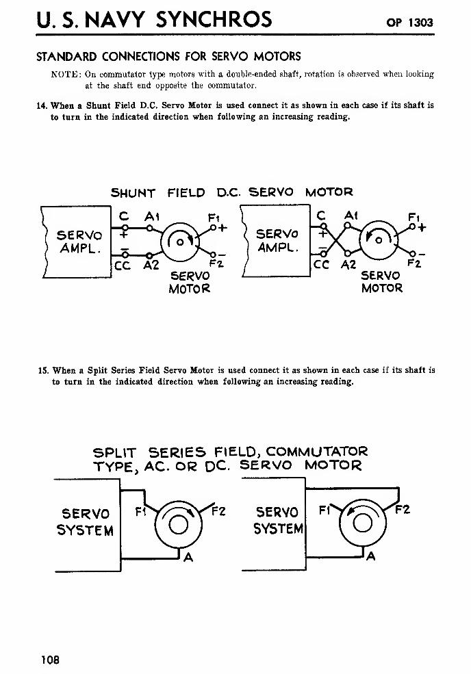
U. S. NAVY SYNCHROS OP 1303
STANDARD CONNECTIONS FOR SERVO MOTORSNOTE : On commutator type motors with a double-ended shaft, rotation is observed when looking
at the shaft end opposite the commutator.
14. When a Shunt Field D.C. Servo Motor is used connect it as shown in each case if its shaft is
to turn in the indicated direction when following an increasing reading.
SERVOAMPL.
SHUNT FIELD D.C SERVO MOTOR
C Al Fi [ I C A1
XCA2 FiSERVOMOTOR
AMPL.i^V
Fi
CC A2 ~ F2SERVOMOTOR
15. When a Split Series Field Servo Motor is used connect it as shown in each case if its shaft is
to turn in the indicated direction when following an increasing reading.
SPLIT SERIES FIELD, COMMUTATORTYPE, AC. OR DC. SERVO MOTOR
SERVOSYSTEM
SERVOSYSTEM
108
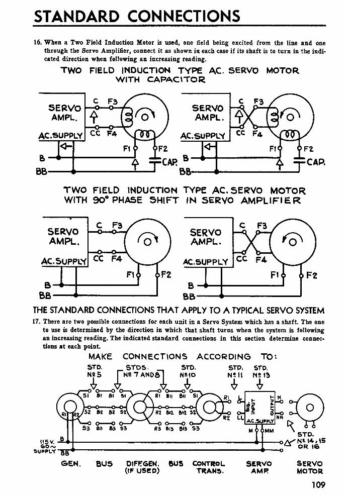
STANDARD CONNECTIONS
16. When a Two Field Induction Motor is used, one field being excited from the line and one
through the Servo Amplifier, connect it as shown in each case if its shaft is to turn in the indi-
cated direction when following an increasing reading.
TWO FIELD INDUCTION TYPE AC SERVO MOTORWITH CAPAOTOR
TWO FIELD INDUCTION TYPE AC. SERVO MOTORWITH 90° PHASE SHIFT IN SERVO AMPLIFIER
SERVOAMPL.
AC.SUPPLY
THE STANDARD CONNECTIONS THAT APPLY TO A TYPICAL SERVO SYSTEM17. There are two possible connections for each unit in a Servo System which has a shaft. The one
to use is determined by the direction in which that shaft turns when the system is following
an increasing reading. The indicated standard connections in this section determine connec-
tions at each point.
MAKE CONNECTIONS ACCORDING TO*.
STD.NS5 nA. A
STDS. STD.
A ASTD. STD.NS11 NS13
115 V.
SUPPLY -gg
O
*
GEN. BUS DIFFTGEN. 6US CONTROL SERVO(IF USED) TRANS. AMR
STD.o/VN* 14,15a OR 16
SERVOMOTOR
109

U. S. NAVY SYNCHROS op 1303
110

ZEROING SYNCHROS
INTRODUCTION
THE ADVANTAGE OF USING ELECTRICAL ZERO AS A REFERENCE
The use of Electrical Zero provides a standard way of aligning Synchro units so that they all work
right when connected together in a Synchro system. Consider, for example, a Gun Director Train
Indicator system. Such a system is used to show, on a dial at each gun station, the position of the
Director, so that the guns may be trained accordingly. If the Indicator dials were mounted on the
shafts of all the Motors, and the Generator shaft was geared to the Gun Director in any convenient
position, then, when the system was first turned on, all of the dials would read differently, and none
of them would show the position of the Gun Director correctly. Before the system could be used it
would be necessary to set the dials so that they all read the true position of the Director. Once this
was done they would continue to read correctly, due to the self-aligning feature of a Synchro.
There are two ways in which this initial adjustment could be made. One way would be to have two
men, one at the Director, and the other at each gun station in turn. They could talk over a phone,
and change the setting of the dial on each Motor until it showed the position of the Director cor-
rectly.
A much better way would be this : First : unclamp the Generator and turn it until the shaft of the
Generator is exactly in the Electrical Zero position when the Director is trained on 0°. Second: set
the dial on each Motor in the system so that, when the Motor's shaft is exactly in the Electrical
Zero position, the dial reads 0°.
The second method has the very important advantage that the mechanical position of the dial on
each Motor's shaft is the same for any system. The dial could, for example, be locked to the shaft
in the correct position at the factory, and it would read correctly when installed on a ship, without any
further adjustment.
This method has the further advantage that trouble in the system always shows up the same way
on the Indicator dials. For example, a short circuit from S2 to S3 causes all the dials to stop at 60°
or 240°.
This method, called "Zeroing" each Synchro, is universally used on Synchro systems.
THE DIAL READING AT ELECTRICAL ZERO (THE "ZERO" READING)
The reading to which the Motor's dial is set when the shaft is at Electrical Zero depends on the
type of Synchro system. On a Gun Director Train Indicator system, and any other system which
has a "0°" on its dial, the dial is set to 0° at Electrical Zero. On a Range Transmission system,
1,000 yards is often used. On a fuze time transmission system 10 seconds is used. On an Engine
Room Telegraph, STOP is used. Before making this adjustment on any system, it is necessary to
know what dial reading to use. In what follows this reading is called the "Zero reading," and the cor-
responding position of the Generator is called the "Zero position."
WHAT IS MEANT BY "ZEROING" A SYNCHRO
"Zeroing" a Synchro means, in general, adjusting it, mechanically, so it will work properly in a
system in which all the other Synchros are zeroed. This mechanical adjustment is usually made by
loosening the lugs that clamp the flange and turning the whole case. In some cases it may be better
to loosen the shaft coupling or some intermediate gear, and to turn the shaft.
(In what follows "Electrical Zero" Voltages means the voltages required to make a Motor turn to
Electrical Zero, that is, 115 volts between Rl and R2, 78 volts in phase with R1-R2 between S2-
Sl and S2-S3, and volts between SI and S3.)
Ill
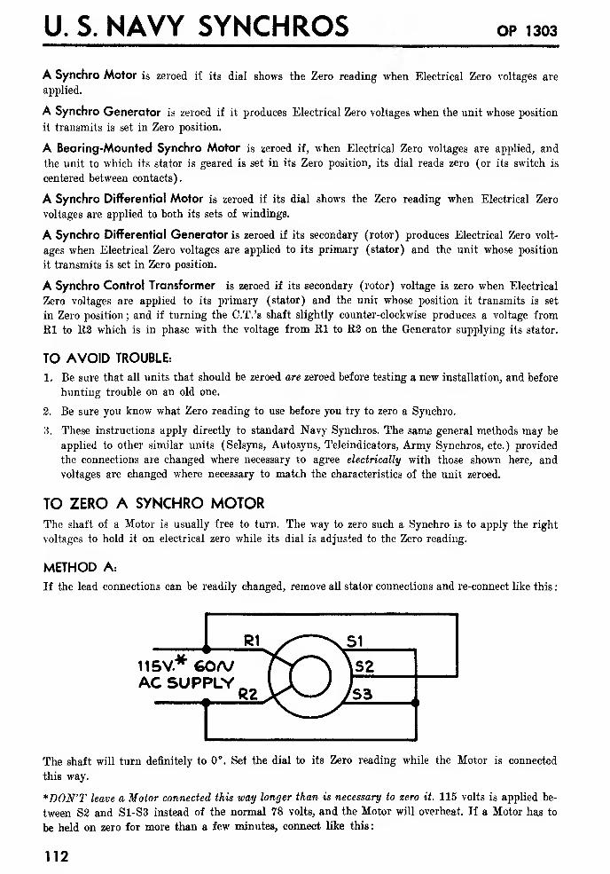
U. S. NAVY SYNCHROS op 1303
A Synchro Motor is zeroed if its dial shows the Zero reading when Electrical Zero voltages are
applied.
A Synchro Generator is zeroed if it produces Electrical Zero voltages when the unit whose position
it transmits is set in Zero position.
A Bearing-Mounted Synchro Motor is zeroed if, when Electrical Zero voltages are applied, and
the unit to which its stator is geared is set in its Zero position, its dial reads zero (or its switch is
centered between contacts).
A Synchro Differential Motor is zeroed if its dial shows the Zero reading when Electrical Zero
voltages are applied to both its sets of windings.
A Synchro Differential Generator is zeroed if its secondary (rotor) produces Electrical Zero volt-
ages when Electrical Zero voltages are applied to its primary (stator) and the unit whose position
it transmits is set in Zero position.
A Synchro Control Transformer is zeroed if its secondary (rotor) voltage is zero when Electrical
Zero voltages are applied to its primary (stator) and the unit whose position it transmits is set
in Zero position ; and if turning the C.T.'s shaft slightly counter-clockwise produces a voltage from
Kl to R2 which is in phase with the voltage from Rl to R2 on the Generator supplying its stator.
TO AVOID TROUBLE:
1. Be sure that all units that should be zeroed are zeroed before testing a new installation, and before
hunting trouble on an old one.
2. Be sure you know what Zero reading to use before you try to zero a Synchro.
3. These instructions apply directly to standard Navy Synchros. The same general methods may be
applied to other similar units (Selsyns, Autosyns, Teleindicators, Army Synchros, etc.) provided
the connections are changed where necessary to agree electrically with those shown here, and
voltages are changed where necessary to match the characteristics of the unit zeroed.
TO ZERO A SYNCHRO MOTORThe shaft of a Motor is usually free to turn. The way to zero such a Synchro is to apply the right
voltages to hold it on electrical zero while its dial is adjusted to the Zero reading.
METHOD A:
If the lead connections can be readily changed, remove all stator connections and re-connect like this
:
115V* 6O/VAC SUPPLY
R̂2
The shaft will turn definitely to 0°. Set the dial to its Zero reading while the Motor is connected
this way.
*DON'T leave a Motor connected this way longer than is necessary to zero it. 115 volts is applied be-
tween S2 and S1-S3 instead of the normal 78 volts, and the Motor will overheat. If a Motor has to
be held on zero for more than a few minutes, connect like this:
112
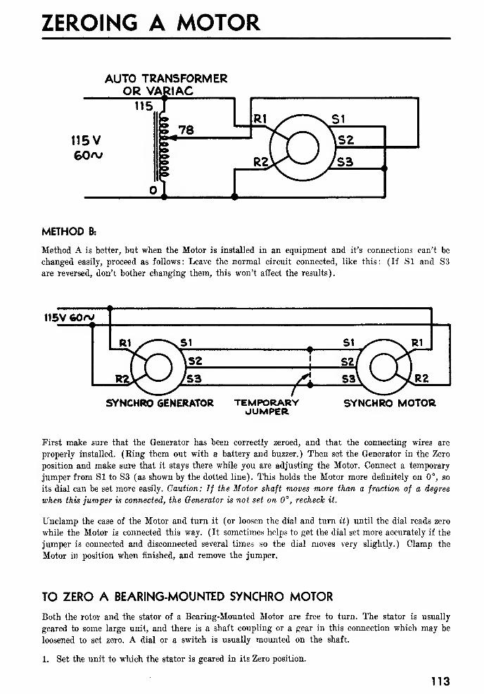
ZEROING A MOTOR
AUTO TRANSFORMEROR VARIAC
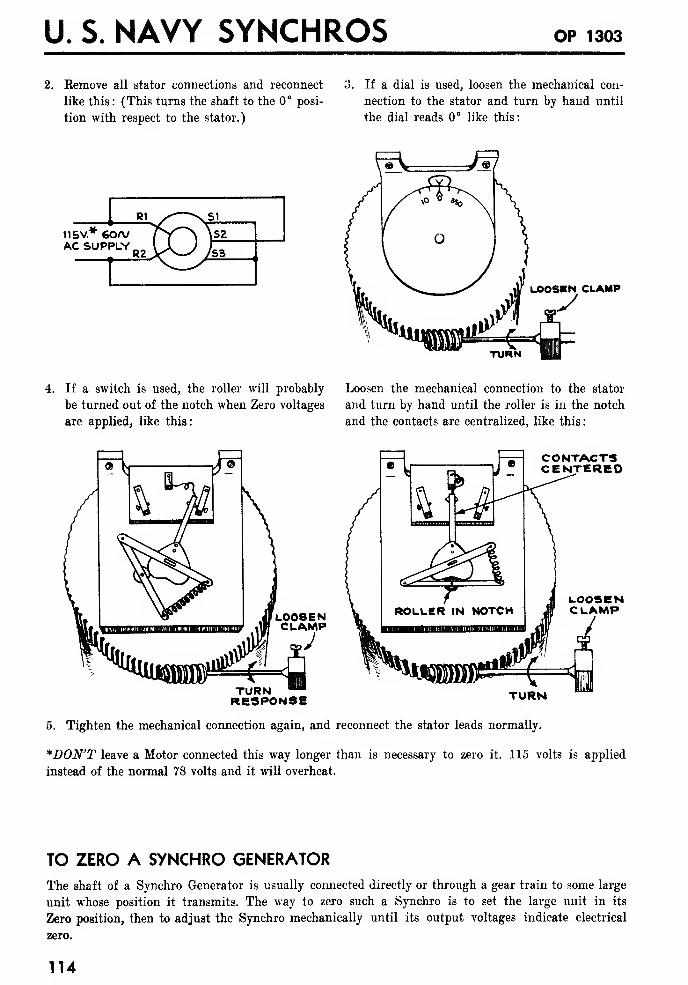
U. S. NAVY SYNCHROS OP 1303
2. Eemove all stator connections and reconnect
like this: (This turns the shaft to the 0° posi-
tion with respect to the stator.)
If a dial is used, loosen the mechanical con-
nection to the stator and turn by hand until
the dial reads 0° like this:
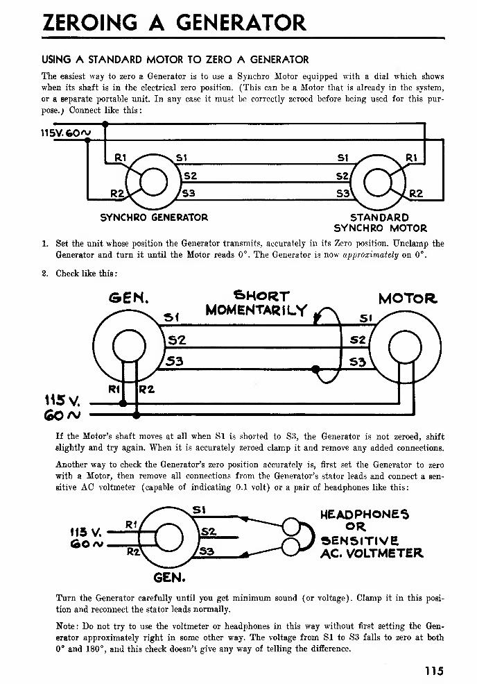
ZEROING A GENERATOR
USING A STANDARD MOTOR TO ZERO A GENERATOR
The easiest way to zero a Generator is to use a Synchro Motor equipped with a dial which shows
when its shaft is in the electrical zero position. (This can be a Motor that is already in the system,
or a separate portable unit. In any case it must he correctly zeroed before being used for this pur-
pose.; Connect like this:
1
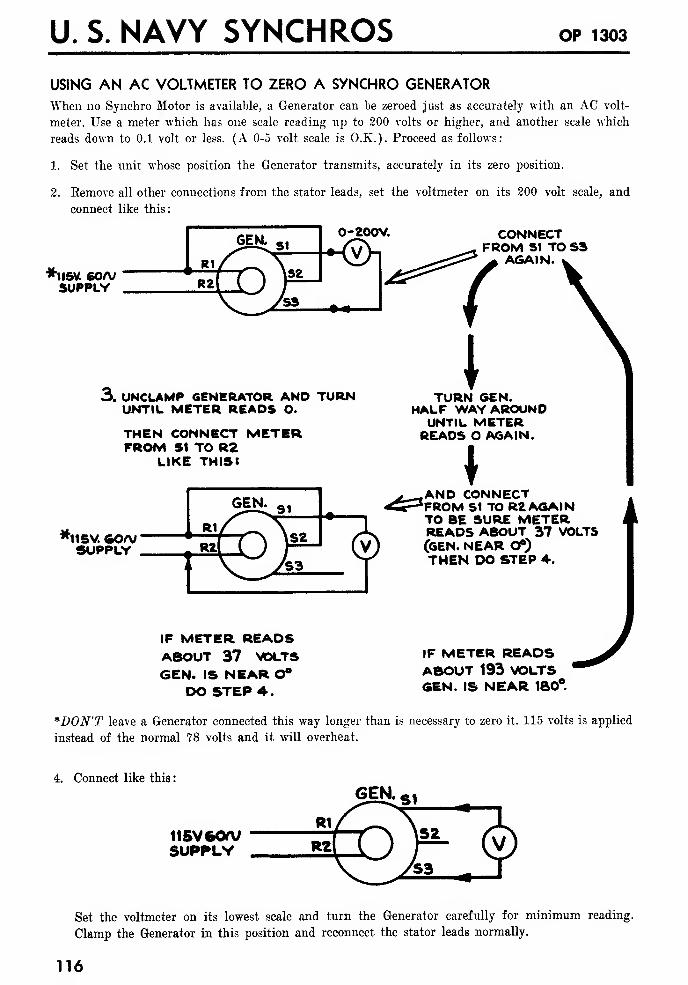
U. S. NAVY SYNCHROS OP 1303
USING AN AC VOLTMETER TO ZERO A SYNCHRO GENERATOR
When no Synchro Motor is available, a Generator can be zeroed just as accurately with an AC volt-
meter. Use a meter which has one scale reading up to 200 volts or higher, and another scale whieh
reads down to 0.1 volt or less. (A 0-5 volt scale is O.K.). Proceed as follows:
1. Set the unit whose position the Generator transmits, accurately in its zero position.
2. Remove all other connections from the stator leads, set the voltmeter on its 200 volt scale, and
connect like this:
0-20OV.
*!l5Vt 60/VSUPPLY
3. UNCLAMP GENERATOR AND TURNUNTIL METER READS O.
THEN CONNECT METERFROM SI TO R2
LIKE THIS:
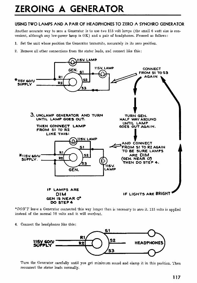
ZEROING A GENERATOR
USING TWO LAMPS AND A PAIR OF HEADPHONES TO ZERO A SYNCHRO GENERATOR
Another accurate way to zero a Generator is to use two 115 volt lamps (the small 6 watt size is con-
venient, although any low-power lamp is OK) and a pair of headphones. Proceed as follows
:
1. Set the unit whose position the Generator transmits, accurately in its zero position.
2. Remove all other connections from the stator leads, and connect like this
:
V115V LAMP
*115V 60AJSUPPLY
CONNECTFROM S1 TO S3
AGAIN
3. UNCLAMP GENERATOR AND TURNUNTIL LAMP GOES OUT-
THEN CONNECT LAMPFROM SI TO RZ
LIKE this:~ V»5V. LAMP
TURN GEN.HALF WAV AROUNDUNTIL LAMP
GOES OUT AGAIN.
*115V 60A/SUPPLY.
\AND CONNECTFROM S1 TO R2 AGAINTO BE SURE LAMPS
ARE DIM(GEN. NEAR C$THEN DO STEP A-.
115V.LAMP
IF LAMPS AREDIM
GEN IS NEAR O*DO STEP 4
IF LIGHTS ARE BRI6HTJ*DON'T leave a Generator connected this way longer than is necessary to zero it. 115 volts is applied
instead of the normal 78 volts and it will overheat.
4. Connect the headphones like this
:
115V 600/SUPPLY
Turn the Generator carefully until you get minimum sound and clamp it in this position. Thenreconnect the stator leads normally.
117
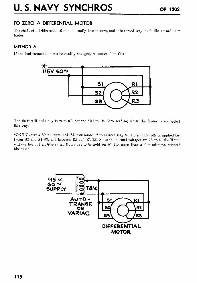
U. S. NAVY SYNCHROS OP 1303
TO ZERO A DIFFERENTIAL MOTORThe shaft of a Differential Motor is usually free to turn, and it is zeroed very much like an ordinary
Motor.
METHOD A:
If the lead connections can be readily changed, re-connect like this
:
The shaft will definitely turn to 0°. Set the dial to its Zero reading while the Motor is connected
this way.
*DON'T leave a Motor connected this way longer than is necessary to zero it. 115 volts is applied be-
tween S2 and S1-S3, and between 112 and R1-K3. Since the normal voltages are 78 volts, the Motor
will overheat. If a Differential Motor has to be held on 0° for more than a few minutes, connect
like this:
115 v.
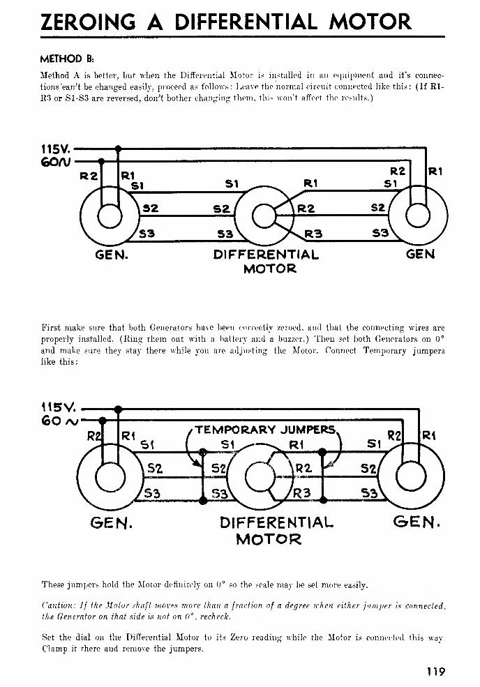
ZEROING A DIFFERENTIAL MOTORMETHOD B:
Method A is better, but when the Differential Motor is installed in an equipment and it's connec-
tions "can't be changed easily, proceed as follows: Leave the normal circuit connected like this: (If Rl-
R3 or S1-S3 are reversed, don't bother changing them, this won't affect the results.)
115V.
goa;
GEN. DIFFERENTIALMOTOR
First make sure that both Generators have been correctly zeroed, and that the connecting wires are
properly installed. (Ring them out with a battery and a buzzer.) Then set both Generators on 0°
and make sure they stay there while you are adjusting the Motor. Connect Temporary jumpers
like this:
H5V.GO /v
GEN. DIFFERENTIALMOTOR
G>EN.
These jumpers hold the Motor definitely on 0° so the scale may be set more easily.
Caution: If the Motor shaft moves more than a fraction of a degree when either jumper us connected,
the Generator on that side k not on 0° , recheck.
Set the dial on the Differential Motor to its Zero reading while the Motor is connected this way
Clamp it there and remove the jumpers.
119
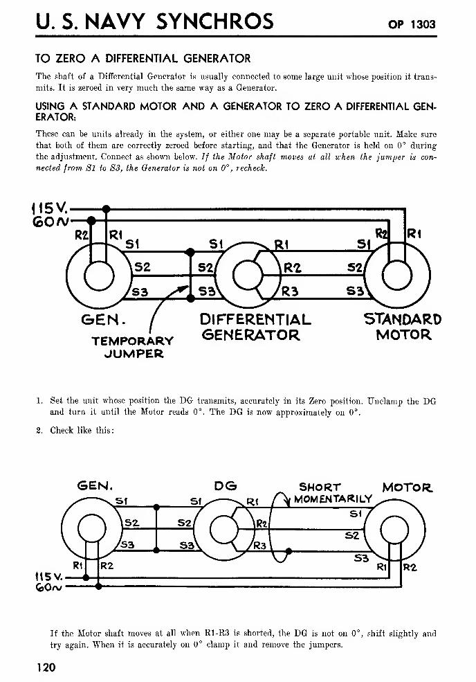
U. S. NAVY SYNCHROS OP 1303
TO ZERO A DIFFERENTIAL GENERATOR
The shaft of a Differential Generator is usually connected to some large unit whose position it trans-
mits. It is zeroed in very much the same way as a Generator.
USING A STANDARD MOTOR AND A GENERATOR TO ZERO A DIFFERENTIAL GEN-ERATOR:
These can be units already in the system, or either one may be a separate portable unit. Make sure
that both of them are correctly zeroed before starting, and that the Generator is held on 0° during
the adjustment. Connect as shown below. If the Motor shaft moves at all when the jumper is con-
nected from Si to S3, the Generator is not on 0° , recheck.
H5V.GO A/
GEN.TEMPORARYJUMPER
DIFFERENTIALGENERATOR
STANDARDMOTOR
1. Set the unit whose position the DG transmits, accurately in its Zero position. Unclamp the DGand turn it until the Motor reads 0°. The DG is now approximately on 0°.
2. Check like this:
GEN.Sf 1

ZEROING A DIFFERENTIAL GENERATORAnother way to check the D6 accurately is to set for 0° reading on the Motor, then disconnect
the Motor completely and connect a pair of headphones or a sensitive AC voltmeter, like this:
SEN. D6 HEAD-PHONES
SENSITIVE-AC. VM.
Turn the DG carefully until you get minimum sound (or voltage). Clamp it in this position,
and remove the jumper.
USING AN AC VOLTMETER TO ZERO A DIFFERENTIAL GENERATOR
A DG may he zeroed accurately with an AC voltmeter. Use one that reads up to 250 volts on one
scale and down to 0.1 volt on another (a 0-5 volt scale is O.K.).
1. Set the unit whose position the DG transmits, accurately in its Zero position.
2. Remove all other connections from the DG's leads, set the voltmeter on its 250 volt scale and
connect like this:
USE AN AC VOLTMETER0-250V
*115V60a/
3. TJnclamp the DG and turn it until the meter reads minimum. The DG is now approximately
on 0°. Reconnect like this:
115V goa;
4. Set the voltmeter on its lowest scale and turn the DG carefully until you get minimum read-
ing. Clamp the DG in this position and reconnect all leads normally.
*DON'T leave a DG connected this way any longer than is necessary to zero it. 115 volts is ap-
plied where the voltage is normally lower, and the DG will overheat.
121
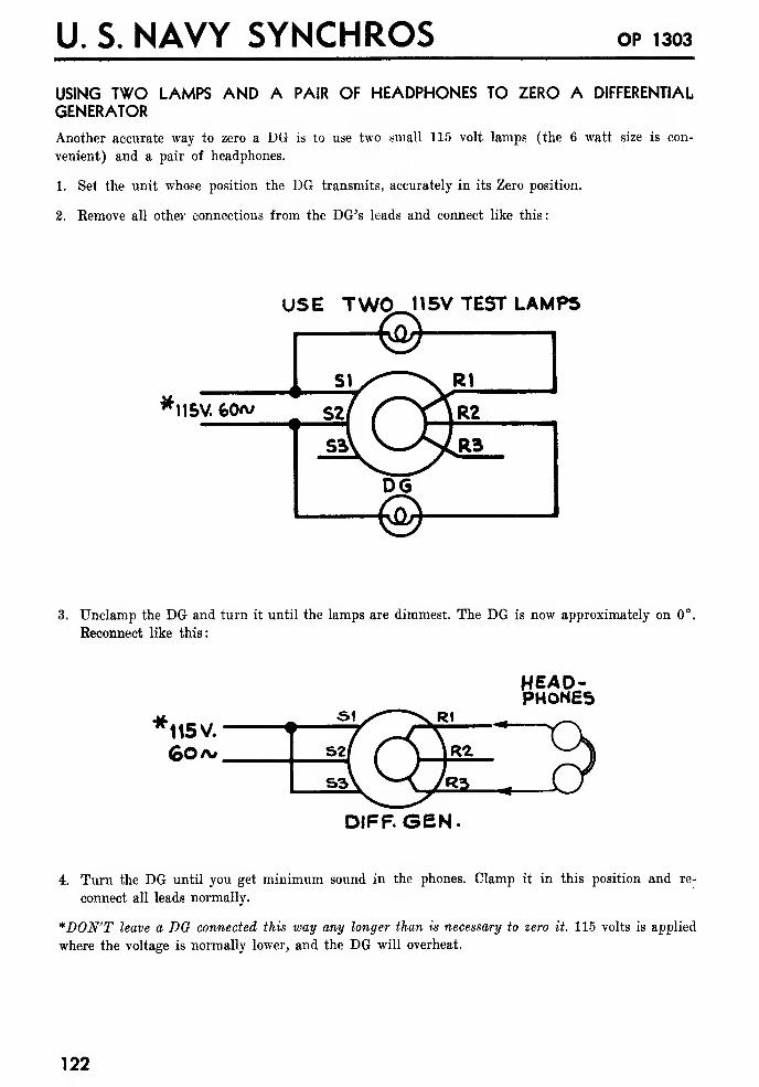
U. S. NAVY SYNCHROS OP 1303
USING TWO LAMPS AND A PAIR OF HEADPHONES TO ZERO A DIFFERENTIAL
GENERATOR
Another accurate way to zero a DG is to use two small 115 volt lamps (the 6 watt size is con-
venient) and a pair of headphones.
1. Set the unit whose position the DG transmits, accurately in its Zero position.
2. Remove all other connections from the DG's leads and connect like this:
r115V 60*/
USE TWO 115V TEST LAMPS
3. Unclamp the DG and turn it until the lamps are dimmest. The DG is now approximately on 0°
Reconnect like this:
HEAD-PHONES
DIFF. GEN.
4. Turn the DG until you get minimum sound in the phones. Clamp it in this position and re-
connect all leads normally.
*DON'T leave a DO connected this way any longer than is necessary to zero it. 115 volts is applied
where the voltage is normally lower, and the DG will overheat.
122
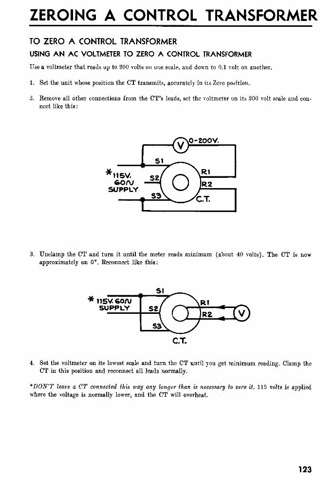
ZEROING A CONTROL TRANSFORMER
TO ZERO A CONTROL TRANSFORMER
USING AN AC VOLTMETER TO ZERO A CONTROL TRANSFORMER
Use a voltmeter that reads up to 200 volts on one scale, and down to 0.1 volt on another.
1. Set the unit whose position the CT transmits, accurately in its Zero position.
2. Remove all other connections from the CT's leads, set the voltmeter on its 200 volt scale and con-
nect like this
:
0-200V.
'MISV.60/V
SUPPLY
3. Unclamp the CT and turn it until the meter reads minimum (about 40 volts). The CT is nowapproximately on 0°. Reconnect like this:
* 115V. 60/VSUPPLY
4. Set the voltmeter on its lowest scale and turn the CT until you get minimum reading. Clamp the
CT in this position and reconnect all leads normally.
*DON'T leave a CT connected this way any longer than is necessary to zero it. 115 volts is applied
where the voltage is normally lower, and the CT will overheat.
123
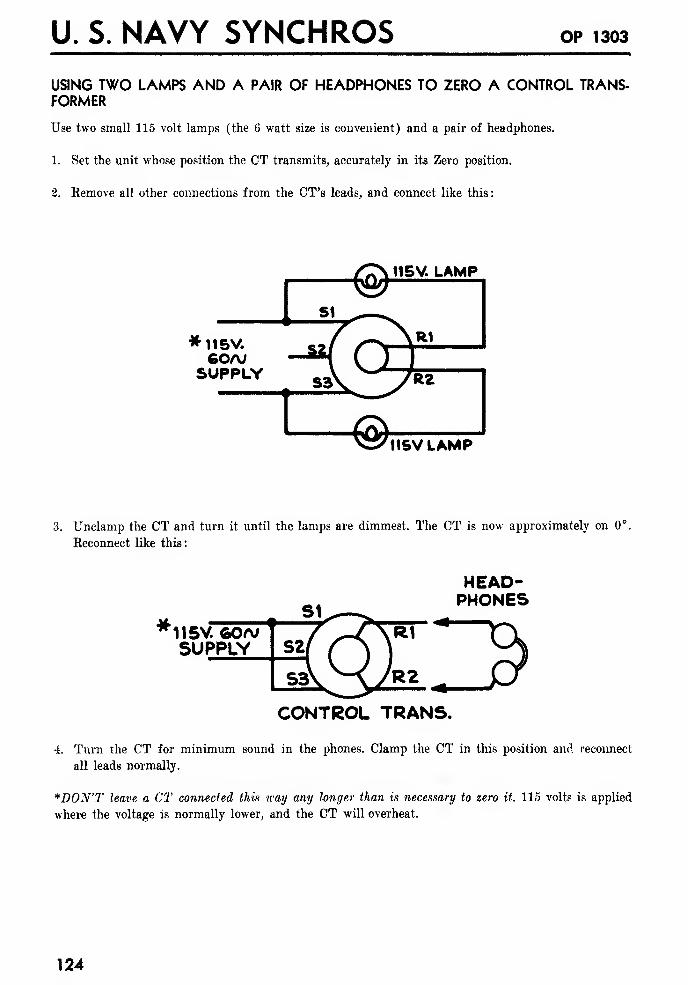
U. S. NAVY SYNCHROS OP 1303
USING TWO LAMPS AND A PAIR OF HEADPHONES TO ZERO A CONTROL TRANS-FORMER
Use two small 115 volt lamps (the 6 watt size is convenient) and a pair of headphones.
1. Set the unit whose position the CT transmits, accurately in its Zero position.
2. Remove all other connections from the CT's leads, and connect like this:
*115V.GOAJ
SUPPLY
115V LAMP
3. Unclamp the CT and turn it until the lamps are dimmest. The CT is now approximately on 0°.
Reconnect like this:
HEAD-PHONES
11 5V 60a;SUPPLYggo>
CONTROL TRANS.
4. Turn the CT for minimum sound in the phones. Clamp the CT in this position and reconnect
all leads normally.
*D0N'T leave a CT connected this way any longer than is necessary to zero it. 115 volts is applied
where the voltage is normally lower, and the CT will overheat.
124
THE MAINTENANCE OF SYNCHROS
The proper attitude toward Synchros can be stated in two sentences—remember them
!
If A Synchro Works OK—Leave It Alone! If It Goes Bad—Replace It!
A Synchro is not just another kind of electric motor. It is a highly precise instrument. Handle it
like you would a watch or an electric meter.
When you install or remove a Synchro from a piece of equipment, do it carefully. Don't hammer the
case, or force it into place. Be sure the shaft is lined up before tightening couplings. Don't drop it
!
NEVER NEVER take a Synchro apart to see what makes it work so well ! Synchros are sealed.
These seals should be broken only by technicians in authorized repair shops.
DON'T try to lubricate a Synchro. When is was manufactured it was lubricated sufficiently to last
a long, long time. Incorrect lubrication will just cause trouble.
If It's OK—Don't Mess With It! If It's Shot—Get A New One!
REPAIRING DEFECTIVE SYNCHROS
This section is written for technicians in authorized Synchro repair shops.
Nobody else has any business trying to repair a Synchro!
GENERAL RULES
1. Dirt and dust are death on Synchros. Before taking one apart : Get a clean, dry place to work.
Spread a large sheet of paper over your bench. Don't work where it's dusty.
Clean off the outside of the Synchro. Dirt from the outside may easily fall inside when you take
it apart.
2. Handle with care. Don't force any parts. If they don't come apart or go together easily, find out
what's wrong. A precision-built instrument like a Synchro can easily be ruined by rough handling.
3. Don't touch the ball races or the balls with bare hands. Wear gloves or handle with a clean, lint-
free cloth such as viscose rayon twill Spec. C-7-8271 dyed white. A little sweat may rust the sur-
face of the steel balls and ruin them.
LUBRICATING A SYNCHRO
A Synchro should be taken apart for lubrication only if it squeaks or sticks. The routine lubrication,
of these units will generally cause more trouble than it will prevent.
Before applying lubricant be sure:
(a) The Synchro needs it.
(b) You know how to apply it.
(c) It is the right lubricant for the job.
OIL is used on all Synchro Motors, and on most other units.
GREASE is used only on Generators, Differential Generators, or Control Transformers that run fre-
quently at high speeds (over 100 RPM), or that run continuously at any speed. It is also used on all
units which have an "H" (high speed) in their designation, as for example, on a 5HG.
125
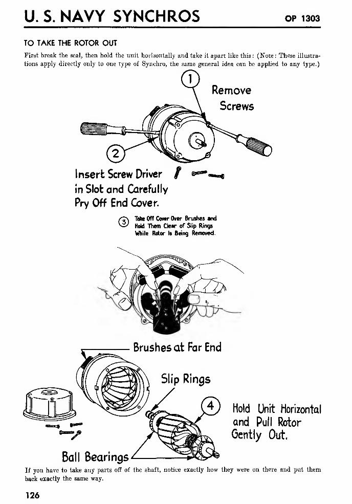
U. S. NAVY SYNCHROS OP 1303
TO TAKE THE ROTOR OUT
First break the seal, then hold the unit horizontally and take it apart like this: (Note: These illustra-
tions apply directly only to one type of Synchro, the same general idea can be applied to any type.)
Remove
Screws
Insert Screw Driver / ©**
in Slot and Carefully
Pry Off End Cover.
© Tafce Off Cover Over Brushes and
Hold Them Clear of Slip Rings
While Rotor Is Being Removed.
Brushes at Far End
Slip Rings
Ball Bearings
Hold Unit Horizontal
and Pull Rotor
Gently Out.
If you have to take any parts off of the shaft, notice exactly how they were on there and put them
back exactly the same way.
126
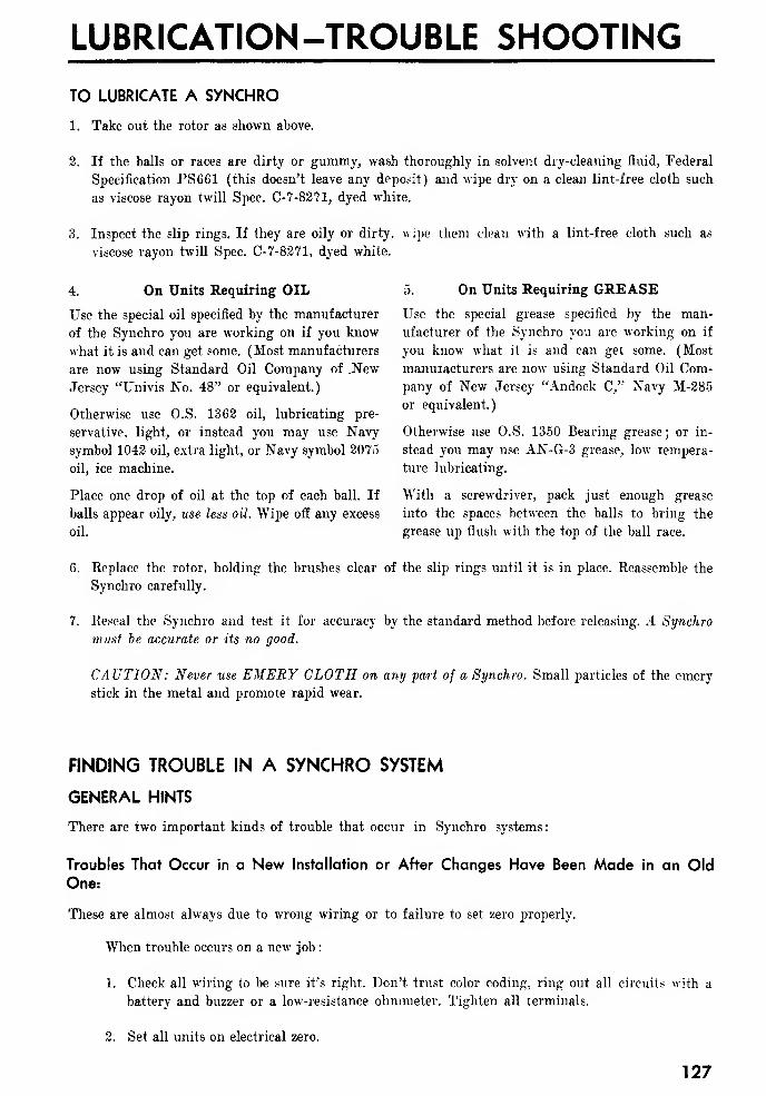
LUBRICATION-TROUBLE SHOOTING
TO LUBRICATE A SYNCHRO
1. Take out the rotor as shown above.
2. If the balls or races are dirty or gummy, wash thoroughly in solvent dry-cleaning fluid, Federal
Specification PS661 (this doesn't leave any deposit) and wipe dry on a clean lint-free cloth such
as viscose rayon twill Spec. C-7-8271, dyed white.
3. Inspect the slip rings. If they are oily or dirty, wipe them clean with a lint-free cloth such as
viscose rayon twill Spec. C-7-8271, dyed white.
4. On Units Requiring OIL
Use the special oil specified by the manufacturer
of the Synchro you are working on if you know
what it is and can get some. (Most manufacturers
are now using Standard Oil Company of NewJersey "Univis No. 48" or equivalent.)
Otherwise use O.S. 1362 oil, lubricating pre-
servative, light, or instead you may use Navy
symbol 1042 oil, extra light, or Navy symbol 2075
oil, ice machine.
5. On Units Requiring GREASE
Use the special grease specified by the man-
ufacturer of the Synchro you are working on if
you know what it is and can get some. (Most
manufacturers are now using Standard Oil Com-
pany of New Jersey "Andock C," Navy M-285
or equivalent.)
Otherwise use O.S. 1350 Bearing grease ; or in-
stead you may use AN-G-3 grease, low tempera-
ture lubricating.
Place one drop of oil at the top of each ball. If With a screwdriver, pack just enough grease
balls appear oily, use less oil. Wipe off any excess into the spaces between the balls to bring the
oil. grease up flush with the top of the ball race.
6. Replace the rotor, holding the brushes clear of the slip rings until it is in place. Reassemble the
Synchro carefully.
7. Reseal the Synchro and test it for accuracy by the standard method before releasing. A Synchro
must be accurate or its no good.
CA UTION: Never use EMERY CLOTH on any part of a Synchro. Small particles of the emery
stick in the metal and promote rapid wear.
FINDING TROUBLE IN A SYNCHRO SYSTEM
GENERAL HINTS
There are two important kinds of trouble that occur in Synchro systems :
Troubles That Occur in a New Installation or After Changes Have Been Made in an OldOne:
These are almost always due to wrong wiring or to failure to set zero properly.
When trouble occurs on a new job
:
1. Check all wiring to be sure it's right. Don't trust color coding, ring out all circuits with a
battery and buzzer or a low-resistance ohmmeter. Tighten all terminals.
2. Set all units on electrical zero.
127
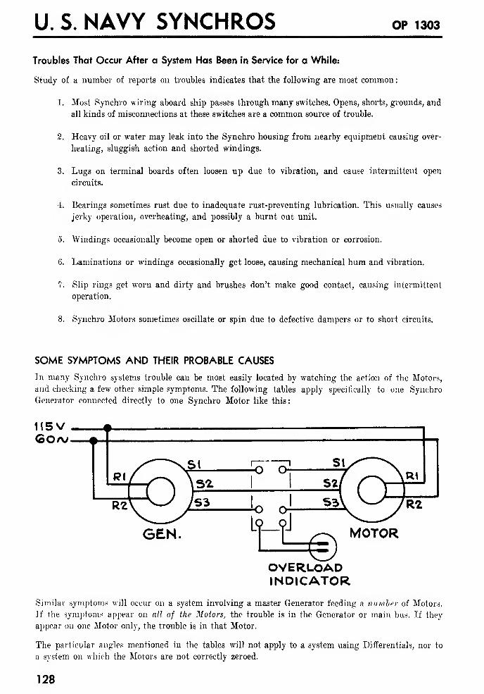
U. S. NAVY SYNCHROS OP 1303
Troubles That Occur After a System Has Been in Service for a While:
Study of a number of reports on troubles indicates that the following are most common
:
1. Most Synchro wiring aboard ship passes through many switches. Opens, shorts, grounds, and
all kinds of misconnections at these switches are a common source of trouble.
2. Heavy oil or water may leak into the Synchro housing from nearby equipment causing over-
heating, sluggish action and shorted windings.
3. Lugs on terminal boards often loosen up due to vibration, and cause intermittent open
circuits.
4. Bearings sometimes rust due to inadequate rust-preventing lubrication. This usually causes
jerky operation, overheating, and possibly a burnt out unit.
5. Windings occasionally become open or shorted due to vibration or corrosion.
6. Laminations or windings occasionally get loose, causing mechanical hum and vibration.
7. Slip rings get worn and dirty and brushes don't make good contact, causing intermittent
operation.
8. Synchro Motors sometimes oscillate or spin due to defective dampers or to short circuits.
SOME SYMPTOMS AND THEIR PROBABLE CAUSES
In many Synchro systems trouble can be most easily located by watching the action of the Motors,
and checking a few other simple symptoms. The following tables apply specifically to one Synchro
Generator connected directly to one Synchro Motor like this:
OVERLOADINDICATOR
Similar symptoms will occur on a system involving a master Generator feeding a number of Motors.
If the symptoms appear on all of the Motors, the trouble is in the Generator or main bus. If they
appear on one Motor only, the trouble is in that Motor.
The particular angles mentioned in the tables will not apply to a system using Differentials, nor to
a system on which the Motors are not correctly zeroed.
128
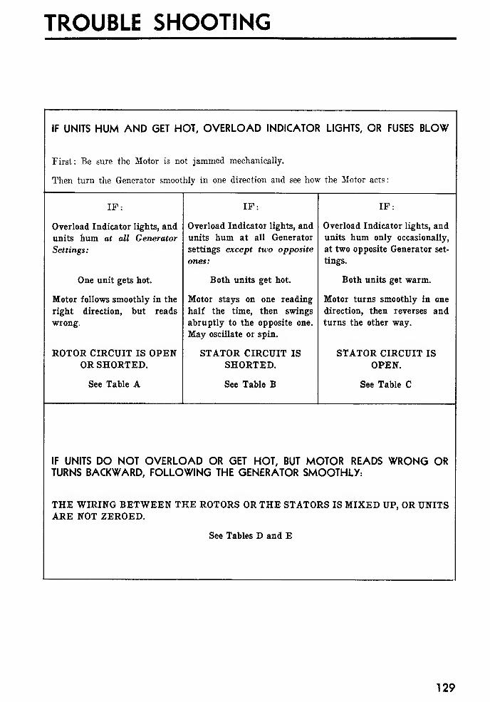
TROUBLE SHOOTING
IF UNITS HUM AND GET HOT, OVERLOAD INDICATOR LIGHTS, OR FUSES BLOW
First: Be sure the Motor is not jammed mechanically.
Then turn the Generator smoothly in one direction and see how the Motor acts
:
IP:
Overload Indicator lights, and
units hum at all Generator
Settings :
One unit gets hot.
Motor follows smoothly in the
right direction, but reads
wrong.
ROTOR CIRCUIT IS OPENOR SHORTED.
See Table A
IF:
Overload Indicator lights, and
units hum at all Generator
settings except two opposite
ones:
Both units get hot.
Motor stays on one reading
half the time, then swings
abruptly to the opposite one.
May oscillate or spin.
STATOR CIRCUIT IS
SHORTED.
See Table B
IF:
Overload Indicator lights, and
units hum only occasionally,
at two opposite Generator set-
tings.
Both units get warm.
Motor turns smoothly in one
direction, then reverses and
turns the other way.
STATOR CIRCUIT IS
OPEN.
See Table C
IF UNITS DO NOT OVERLOAD OR GET HOT, BUT MOTOR READS WRONG ORTURNS BACKWARD, FOLLOWING THE GENERATOR SMOOTHLY:
THE WIRING BETWEEN THE ROTORS OR THE STATORS IS MIXED UP, OR UNITSARE NOT ZEROED.
See Tables D and E
129
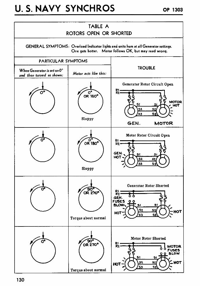
U. S. NAVY SYNCHROS OP 1303
TABLE AROTORS OPEN OR SHORTED
GENERAL SYMPTOMS: Overload Indicator lights and units hum at all Generator settings.
One gets hotter. Motor follows OK, but may read wrong.
PARTICULAR SYMPTOMS
When Generator is set on 0°
and then turned as shown:Motor acts like this:
TROUBLE
Generator Rotor Circuit Open
Sloppy
MOTOR• HOT
GEN. MOTOR
Motor Rotor Circuit Open
Sloppy
GENHOT^
R\—R2
—
GEN.FUSESBUOWs
HOT-
Generator Rotor Shorted
Torque about normal
Motor Rotor Shorted
Torque about normal
HOT-
ll MOTOR6 FUSESBLOW
:.hot
130
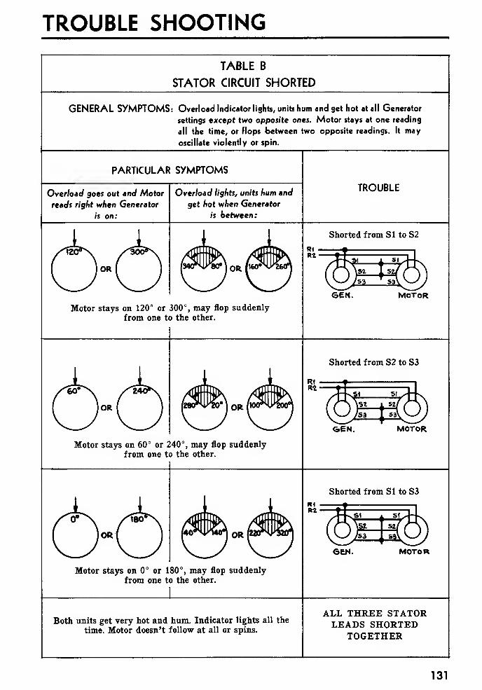
TROUBLE SHOOTING
TABLE B
STATOR CIRCUIT SHORTED
GENERAL SYMPTOMS: Overload Indicator lights, units hum and get hot at all Generator
settings except two opposite ones. Motor stays at one reading
all the time, or flops between two opposite readings. It may
oscillate violently or spin.
PARTICULAR SYMPTOMS
Overload goes out and Motor
reads right when Generator
is on:
Overload lights, units hum and
get hot when Generator
is between:
TROUBLE
Shorted from SI to S2
GEN. MOTORMotor stays on 120° or 300°, may flop suddenly
from one to the other.
Shorted from S2 to S3
GEN. MOTOR
Motor stays on 60° or 240°, may flop suddenlyfrom one to the other.
cb^cb
Shorted from SI to S3
GEN. MOTOR
Motor stays on 0° or 180°, may flop suddenlyfrom one to the other.
Both units get very hot and hum. Indicator lights all the
time. Motor doesn't follow at all or spins.
ALL THREE STATORLEADS SHORTED
TOGETHER
131
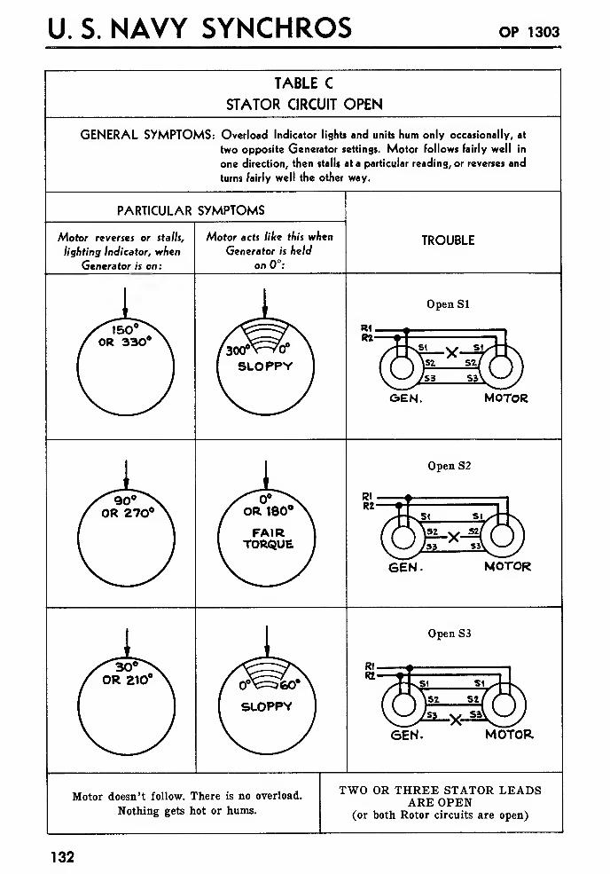
U. S. NAVY SYNCHROS OP 1303
TABLE C
STATOR CIRCUIT OPEN
GENERAL SYMPTOMS: Overload Indicator lights and units hum only occasionally, at
two opposite Generator settings. Motor follows fairly well in
one direction, then stalls at a particular reading, or reverses and
turns fairly well the other way.
PARTICULAR SYMPTOMS
Motor reverses or stalls,
lighting Indicator, when
Generator is on:
Motor acts like this when
Generator is held
on 0°:
TROUBLE
Open SI
GEN. MOTOR
Open S2
SEN. MOTOR
Open S3
6EN. MOTOR
Motor doesn't follow. There is no overload.
Nothing gets hot or hums.
TWO OR THREE STATOR LEADSARE OPEN
(or both Rotor circuits are open)
132
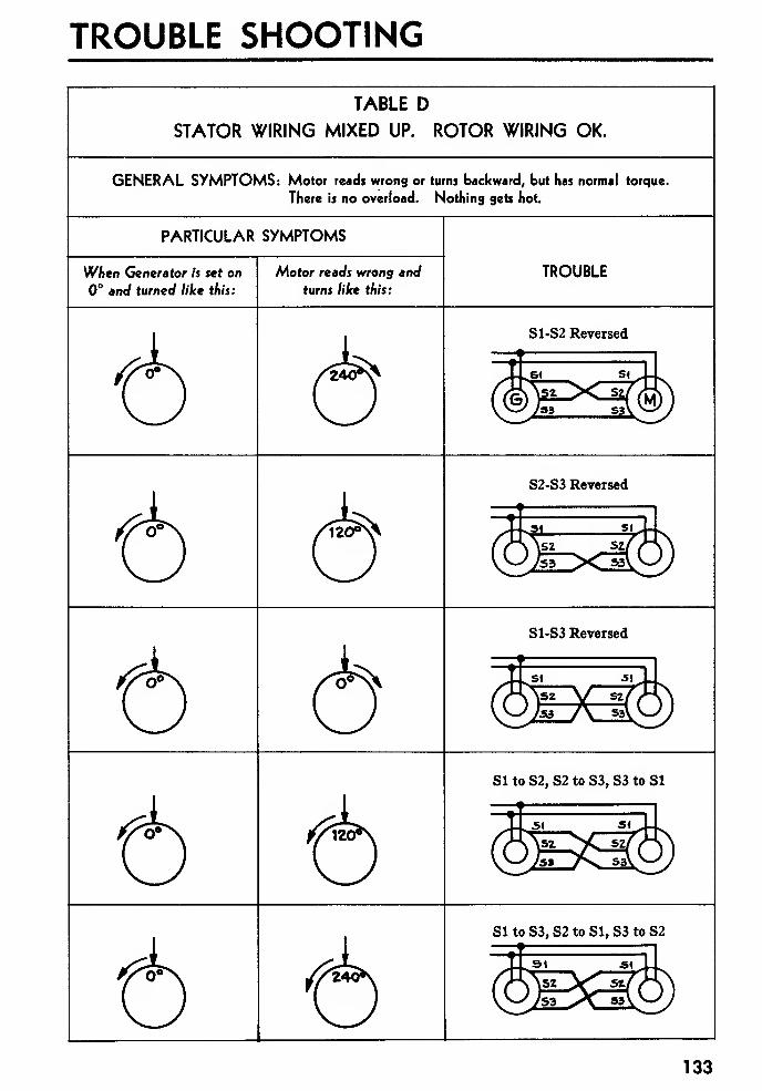
TROUBLE SHOOTING
TABLE D
STATOR WIRING MIXED UP. ROTOR WIRING OK.
GENERAL SYMPTOMS: Motor reads wrong or turns backward, but has normal torque.
There is no overload. Nothing gets hot.
PARTICULAR SYMPTOMS
When Generator is set on
0° and turned like this:
Motor reads wrong and
turns like this:
TROUBLE
S1-S2 Reversed
S2-S3 Reversed
S1-S3 Reversed
SltoS2,S2toS3,S3toSl
SI to S3, S2 to SI, S3 to S2
133
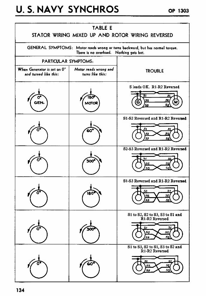
U. S. NAVY SYNCHROS OP 1303
TABLE E
STATOR WIRING MIXED UP AND ROTOR WIRING REVERSED
GENERAL SYMPTOMS: Motor reads wrong or turns backward, but has normal torque.
There is no overload. Nothing gets hot.
PARTICULAR SYMPTOMS:
When Generator is set on 0°
and turned like this:
Motor reads wrong and
turns like this:TROUBLE
S leads OK. R1-R2 Reversed
iE=i®S1-S2 Reversed and R1-R2 Reversed
S2-S3 Reversed and R1-R2 Reversed
S1-S3 Reversed and R1-R2 ReversedX
SI to S2, S2 to S3, S3 to SI andR1-R2 Reversed
SI to S3, S2 to SI, S3 to S2 andR1-R2 Reversed
134
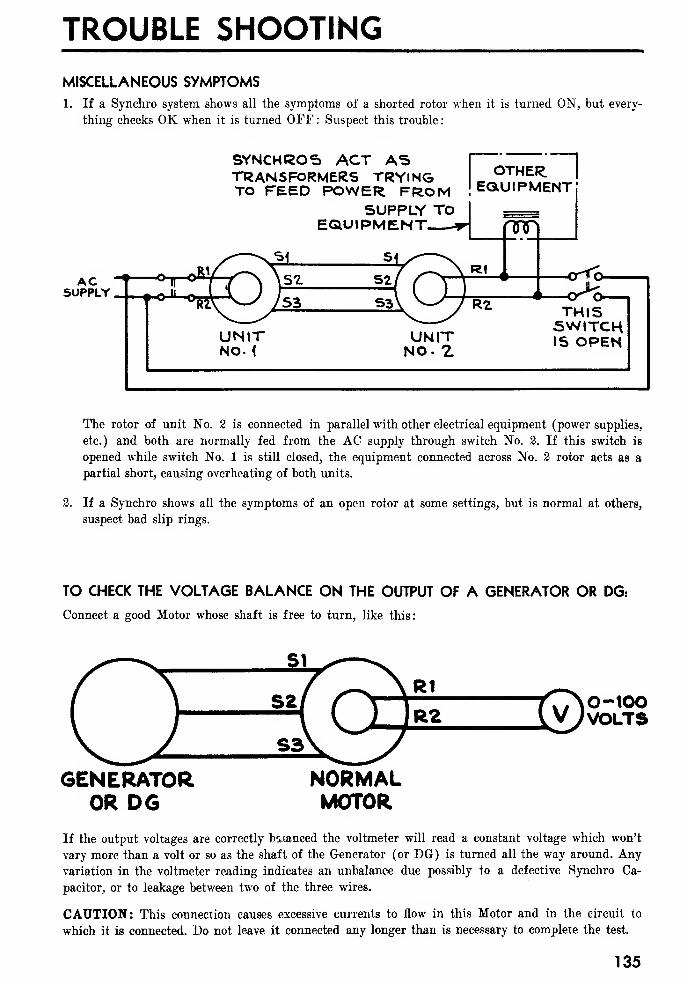
TROUBLE SHOOTING
MISCELLANEOUS SYMPTOMS1. If a Synchro system shows all the symptoms of a shorted rotor when it is turned ON, but every-
thing checks OK when it is turned OFF : Suspect this trouble
:
ACSUPPLY
SYNCHROS ACT ASTRANSFORMERS TRYINGTO FEED POWER FROM
SUPPLY TOEQUIPMENT ji
UNITNO- <
UNITNO. Z
OTHER.I
EQUIPMENT
nnn
3@R1
R2
-crtfo-
THISSWITCHIS OPEN
The rotor of unit No. 2 is connected in parallel with other electrical equipment (power supplies,
etc.) and both are normally fed from the AC supply through switch No. 2. If this switch is
opened while switch No. 1 is still closed, the equipment connected across No. 2 rotor acts as a
partial short, causing overheating of both units.
2. If a Synchro shows all the symptoms of an open rotor at some settings, but is normal at others,
suspect bad slip rings.
TO CHECK THE VOLTAGE BALANCE ON THE OUTPUT OF A GENERATOR OR DG:
Connect a good Motor whose shaft is free to turn, like this:
0-100VOLTS
GENERATOROR DG
NORMALMOTOR
If the output voltages are correctly balanced the voltmeter will read a constant voltage which won't
vary more than a volt or so as the shaft of the Generator (or DG) is turned all the way around. Any
variation in the voltmeter reading indicates an unbalance due possibly to a defective Synchro Ca-
pacitor, or to leakage between two of the three wires.
CAUTION: This connection causes excessive currents to flow in this Motor and in the circuit to
which it is connected. Do not leave it connected any longer than is necessary to complete the test.
135
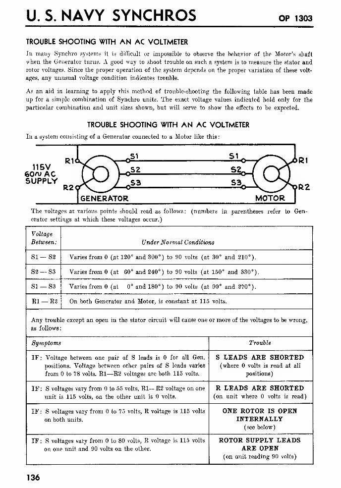
U. S. NAVY SYNCHROS OP 1303
TROUBLE SHOOTING WITH AN AC VOLTMETER
In many Synchro systems it is difficult or impossible to observe the behavior of the Motor's shaft
when the Generator turns. A good way to shoot trouble on such a system is to measure the stator and
rotor voltages. Since the proper operation of the system depends on the proper variation of these volt-
ages, any unusual voltage condition indicates trouble.
As an aid in learning to apply this method of trouble-shooting the following table has been madeup for a simple combination of Synchro units. The exact voltage values indicated hold only for the
particular combination and unit sizes shown, but will serve to show the effects to be expected.
TROUBLE SHOOTING WITH AN AC VOLTMETER
In a system consisting of a Generator connected to a Motor like this
:
115V60n; ACSUPPLY
GENERATOR MOTORThe voltages at various points should read as follows: (numbers in parentheses refer to Gen-
erator settings at which these voltages occur.)
Voltage
Between:
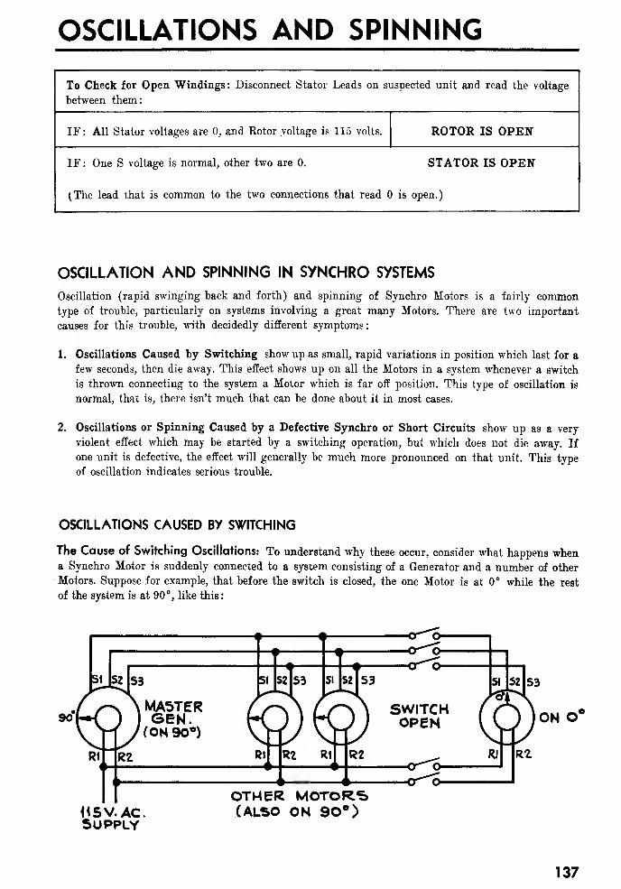
OSCILLATIONS AND SPINNING
To Check for Open Windings: Disconnect Stator Leads on suspected unit and read the voltage
between them:
IF: All Stator voltages are 0, and Kotor voltage is 115 volts. ROTOR IS OPEN
IF : One S voltage is normal, other two are 0. STATOR IS OPEN
(The lead that is common to the two connections that read is open.)
OSCILLATION AND SPINNING IN SYNCHRO SYSTEMS
Oscillation (rapid swinging back and forth) and spinning of Synchro Motors is a fairly commontype of trouble, particularly on systems involving a great many Motors. There are two important
causes for this trouble, with decidedly different symptoms:
1. Oscillations Caused by Switching show up as small, rapid variations in position which last for a
few seconds, then die away. This effect shows up on all the Motors in a system whenever a switch
is thrown connecting to the system a Motor which is far off position. This type of oscillation is
normal, that is, there isn't much that can be done about it in most cases.
2. Oscillations or Spinning Caused by a Defective Synchro or Short Circuits show up as a very
violent effect which may be started by a switching operation, but which does not die away. If
one unit is defective, the effect will generally be much more pronounced on that unit. This type
of oscillation indicates serious trouble.
OSCILLATIONS CAUSED BY SWITCHING
The Cause of Switching Oscillations: To understand why these occur, consider what happens whena Synchro Motor is suddenly connected to a system consisting of a Generator and a number of other
Motors. Suppose for example, that before the switch is closed, the one Motor is at 0° while the rest
of the system is at 90°, like this
:
<r-S-
SUPPLY
OTHER MOTORS(ALSO ON 90°)
ON 0°
137
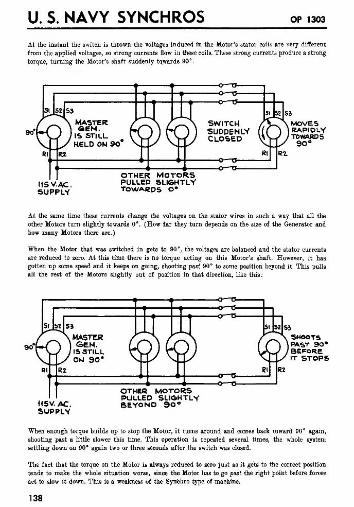
U. S. NAVY SYNCHROS OP 1303
At the instant the switch is thrown the voltages induced in the Motor's stator coils are very different
from the applied voltages, so strong currents flow in these coils. These strong currents produce a strong
torque, turning the Motor's shaft suddenly tQwards 90°.
MASTERGEN.IS STILLHELD ON 90°
O—O-
-O—TJ-
o
—
a-
SWITCHSUDDENLYCLOSED
115 V.AC.SUPPLY
OTHER MOTORSPULLED SLIGHTLYTOWARDS 0°
MOVESRAP»OLYTOWARDS90°
At the same time these currents change the voltages on the stator wires in such a way that all the
other Motors turn slightly towards 0°. (How far they turn depends on the size of the Generator and
how many Motors there are.)
When the Motor that was switched in gets to 90°, the voltages are balanced and the stator currents
are reduced to zero. At this time there is no torque acting on this Motor's shaft. However, it has
gotten up some speed and it keeps on going, shooting past 90° to some position beyond it. This pulls
all the rest of the Motors slightly out of position in that direction, like this
:
cr ~g
©
—
"&
O—T>
SHOOTSPAST 90"BEFOREIT STOPS
H5V.AC.SUPPLY
OTHER MOTORSPULLED SLIGHTLYBEYOND 90°
When enough torque builds up to stop the Motor, it turns around and comes back toward 90° again,
shooting past a little slower this time. This operation is repeated several times, the whole system
settling down on 90° again two or three seconds after the switch was closed.
The fact that the torque on the Motor is always reduced to zero just as it gets to the correct position
tends to make the whole situation worse, since the Motor has to go past the right point before forces
act to slow it down. This is a weakness of the Syn'chro type of machine.
138
OSCILLATIONS AND SPINNING
The Correction of Switching Oscillations: Although nothing much can be done about it when this
trouble shows up after installation, care in planning 6 efo re installation will minimize it. The follow-
ing factors should be considered:
1. Any Motor which is normally switched into a system should be the smallest size unit that will
operate with sufficient accuracy in that position. A smaller Motor draws less current and causes
less disturbance when switched in.
2. Anything mounted on the shaft of such a Motor should be as light and as small in diameter as
is possible. Anything that increases the inertia of the rotor makes the oscillation worse.
3. The Generator should be plenty big enough to handle the number of Motors attached to it so that
these disturbances do not change its output voltages too much. For the same reason long runs of
small wire should be avoided.
4. Overload Indicators or other devices that are connected in series with the Generator's stator leads
will tend to make these effects worse.
5. In cases where a Differential unit with a Capacitor across it stator leads is switched into the sys-
tem, the Capacitor may aggravate the disturbance caused, since it draws a heavy initial charging
current if the switch is closed at just the wrong point in the cycle of the AC voltage.
OSCILLATIONS OR SPINNING CAUSED BY A DEFECTIVE SYNCHRO OR SHORT CIRCUIT
IF : Switching or sudden changes in position start spinning or oscillations that don't die away,and the trouble shows up much more on one Motor in the system than it does on the others
:
THE DAMPER ON THAT MOTOR IS BAD (or a Generator was installed by mistake).
Replace the Motor with one from spares, and send it in for repair.
IF : All the Motors on the system oscillate or spin equally hard.
TWO OR POSSIBLY ALL THREE STATOR LEADS ARE SHORTED TOGETHER.
139

U. S. NAVY SYNCHROS op 1303
140
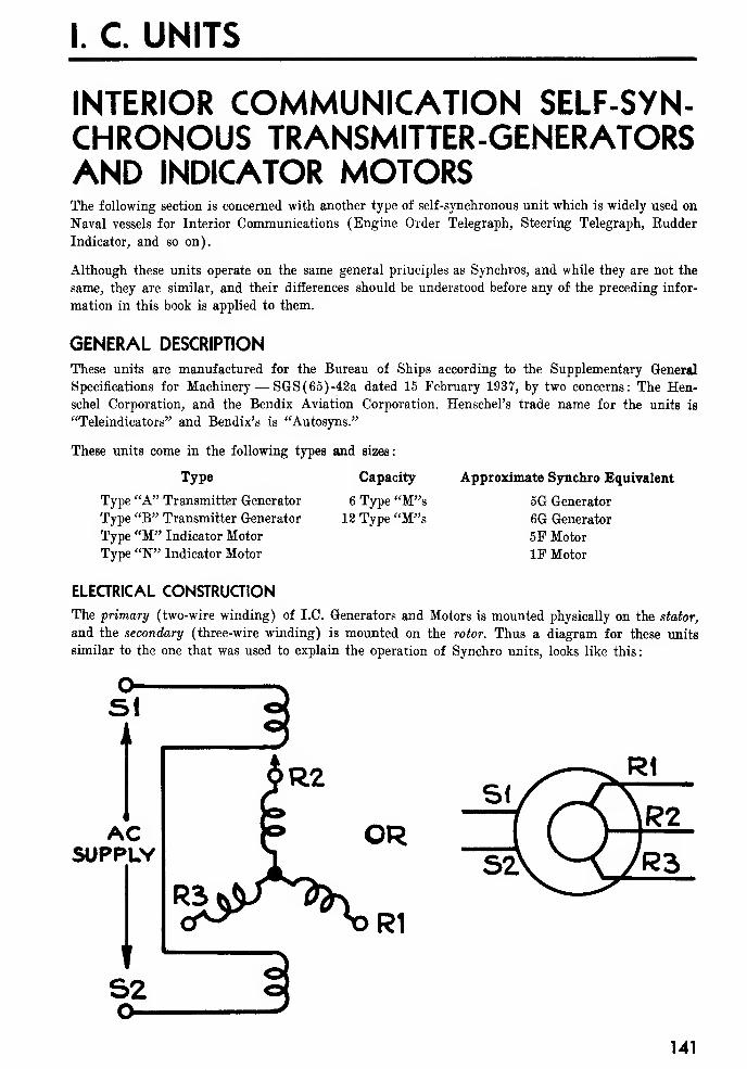
I. C. UNITS
INTERIOR COMMUNICATION SELF-SYN-CHRONOUS TRANSMITTER-GENERATORSAND INDICATOR MOTORSThe following section is concerned with another type of self-synchronous unit which is widely used on
Naval vessels for Interior Communications (Engine Order Telegraph, Steering Telegraph, Rudder
Indicator, and so on).
Although these units operate on the same general principles as Synchros, and while they are not the
same, they are similar, and their differences should be understood before any of the preceding infor-
mation in this book is applied to them.
GENERAL DESCRIPTION
These units are manufactured for the Bureau of Ships according to the Supplementary General
Specifications for Machinery— SGS(65)-42a dated 15 February 1937, by two concerns: The Hen-schel Corporation, and the Bendix Aviation Corporation. Henschel's trade name for the units is
"Teleindieators" and Bendix's is "Autosyns."
These units come in the following types and sizes:
Approximate Synchro Equivalent
5G Generator
6G Generator
5P Motor
IF Motor
Type Capacity
Type "A" Transmitter Generator 6 Type "M"sType "B" Transmitter Generator 12 Type "M"s
Type "M" Indicator Motor
Type "W Indicator Motor
ELECTRICAL CONSTRUCTION
The primary (two-wire winding) of I.C. Generators and Motors is mounted physically on the stator,
and the secondary (three-wire winding) is mounted on the rotor. Thus a diagram for these units
similar to the one that was used to explain the operation of Synchro units, looks like this
:
SIA
ACSUPPLY
t
S2
$R2
P OR
141

U. S. NAVY SYNCHROS OP 1303
VOLTAGE RATINGS
The voltage ratings on the IC units are the same as on Synchros, that is, with 115 volts, 60 cycles
AC applied to the two stator leads, a maximum of 90 volts is produced between any two rotor leads.
DIRECTION OF ROTATION
The "Electrical Zero" position on these units is
denned (very much like the Synchro) as the
position where rotor coil 2 lines up with the
stator coils. To turn an Indicator Motor to Elec-
trical Zero, 115 volts is applied to the stator,
and 78 volts to the rotor as shown
:
78V.
ONO°
Now if El and R2 are shorted together, and 78
volts applied between them and E3, the rotor
turns clockwise 120° like this:
(If 78 volts is applied in a similar manner be-
tween S1-S2 and S3 on a Synchro, the rotor
would turn counter-clockwise 120°.)
ON 120*
If R2 and R3 are shorted and 78 volts applied
like this the rotor turns another 120°
:
ON 240142
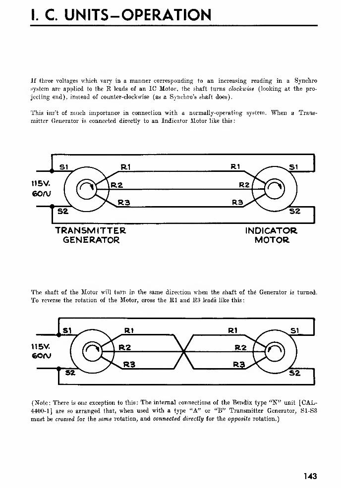
I. C. UNITS-OPERATION
If three voltages which vary in a manner corresponding to an increasing reading in a Synchro
system are applied to the R leads of an IC Motor, the shaft turns clockwise (looking at the pro-
jecting end), instead of counter-clockwise (as a Synchro's shaft does).
This isn't of much importance in connection with a normally-operating system. When a Trans-
mitter Generator is connected directly to an Indicator Motor like this
:
TRANSMITTERGENERATOR
INDICATORMOTOR
The shaft of the Motor will turn in the same direction when the shaft of the' Generator is turned.
To reverse the rotation of the Motor, cross the Rl and R3 leads like this
:
(Note: There is one exception to this: The internal connections of the Bendix type "W unit [CAL-
4400-1] are so arranged that, when used with a type "A" or "B" Transmitter Generator, S1-S3
must be crossed for the same rotation, and connected directly for the opposite rotation.)
143
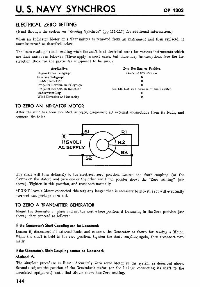
U. S. NAVY SYNCHROS OP 1303
ELECTRICAL ZERO SETTING
(Bead through the section on "Zeroing Synchros" (pp 111-11?) for additional information.)
When an Indicator Motor or a Transmitter is removed from an instrument and then replaced, it
must be zeroed as described below.
The "zero reading" (scale reading when the shaft is at electrical zero) for various instruments which
use these units is as follows: (These apply in most cases, but there may be exceptions. See the In-
struction Book for the particular equipment to be sure.)
Application
Engine Order Telegraph
Steering Telegraph
Rudder Indicator
Propeller Revolution Telegraph
Propeller Revolution Indicator
Underwater LogWind Direction and Intensity
TO ZERO AN INDICATOR MOTORAfter the unit has been mounted in place, disconnect all external connections from its leads, and
connect like this
:
Zero Reading or Position
Center of STOP Order
See I.B. Not at because of limit switch.
11 5VOLTAC SUPPLY
The shaft will turn definitely to the electrical zero position. Loosen the shaft coupling (or the
clamps on the stator) and turn one or the other until the pointer shows the "Zero reading" (see
above). Tighten in this position, and reconnect normally.
*DON'T leave a Motor connected this way any longer than is necessary to zero it, as it will eventually
overheat and perhaps burn out.
TO ZERO A TRANSMITTER GENERATORMount the Generator in place and set the unit whose position it transmits, in the Zero position (see
above), then proceed as follows:
If the Generator's Shaft Coupling can be Loosened:
Loosen it, disconnect all external leads, and connect the Generator as shown for zeroing a Motor.
While the shaft is held in the zero position, tighten the shaft coupling again, then reconnect nor-
mally.
If the Generator's Shaft Coupling cannot be Loosened:
Method A:
The simplest procedure is First: Accurately Zero some Motor in the system as described above.
Second: Adjust the position of the Generator's stator (or the linkage connecting its shaft to the
associated equipment) until that Motor shows the Zero reading.
144

I. C UNITS-ZEROING
Method B:
If Method A isn't practical, proceed as follows, using a couple of small 115 volt lamps (the 6 watt
size is convenient) and a pair of headphones (or a low scale AC voltmeter)
:
1. Set the unit whose position the Transmitter Generator transmits, accurately in its Zero position.
2. Remove all connections from the rotor leads, and connect like this:
115Y LAMP
*I15V. feOA/AC SUPPLY
@-
V >^R3 , J LAMP f
CONNEGTFROM R1 TO R3
AGAIN
GEN.
3 UNCLAMP GENERATOR AND TURNUNTIL. LAMP GOES OUT,
THEN CONNECT LAMP FROMR3 TO S2 LIKE THIS.
115V. LAMP
"iisvcso/vAC SUPPLY.
115V. LAMPIF LAMPS ARE
DIMGEN. IS NEAR 0°DO STEP A-
ITURN GEN.
HALF WAY AROUNDUNTIL LAMP
GOES OUT AGAIN.
IAND CONNECTFROM R3 TO 52 AGAINTO BE SURE LAMPSARE DIM(GEN. NEAR 0°)THEN DO STEP 4-.
IF LAMPS AREBRIGHT
4. Connect the headphones or voltmeter like this
:
SEN
*115V 60fVAC SUPPLY
HEADPHONES OP. ACVM.
Turn the Generator carefully until you get minimum sound or voltage and clamp it in this posi-
tion. Reconnect the rotor leads normally.
145
U. S. NAVY SYNCHROS op 1303
TROUBLE SHOOTINGThe Trouble-shooting information for Synchros (see pages 127 to 13?) may be applied to IC systems
if the following changes are made
:
Where the book shows "rotor" substitute "stator."£C
I. C UNITS-MAINTENANCE
MAINTENANCE
The maintenance procedure on these units is quite different from that followed on Synchros. They
may be taken apart, if necessary, by a qualified technician on shipboard. Rotor assemblies are carried
in spares if needed. Before taking a unit apart, read through the instructions for Synchro repairmen
(page 125), the same care should be exercised with these units.
CLEANING BRUSHES OR SLIP RINGS
When there is trouble in the rotor circuit remove the cover over the brushes (the nameplate on
Henschel machines) and inspect the brushes and slip rings. If they are corroded or dirty, remove the
brushes and clean off brushes and slip rings. Use a clean, lint-free cloth or chamois. In bad cases
of corrosion or pitting, very fine sandpaper may be used lightly on the slip rings.
OILING OR REPLACING A ROTOR
If a unit needs oiling, or a new rotor, it is necessary to take it apart. First remove the brushes, and
the screws that hold the unit together. Then pull it apart carefully and remove the rotor. Inspect
the ball bearings to be sure they are in good condition, and replace them from spares if necessary.
If new bearings are used clean off the thick vaseline used to prevent rust before installing them.
If oil is needed, apply one drop at the top of each ball, (or less if balls are oily). Use a high grade
light oil as recommended by the manufacturer, or, if you can't get this use Standard Oil Company of
New Jersey "Univis No. 48," or watch oil.
When replacing a bearing in the front end frame, don't disturb the shims. Four shims are usually
needed, allowing an end play of .01 to .015 inches.
Inspect the oscillation damper. Clean it thoroughly and cover the rubbing surfaces with a light film
of vaseline before assembling the unit.
CHARACTERISTICS OF BUREAU OF SHIPS SELF-SYNCHRONOUS UNITS
The following tables show the important characteristics of current types of these units, and, for com-
parison, of the equivalent Synchros.
147

U. S. NAVY SYNCHROS OP 1303
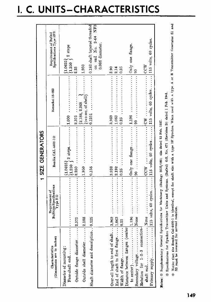
I. C. UNITS-CHARACTERISTICS
COon
o<OHLU
oLUNto
t3 co
«e
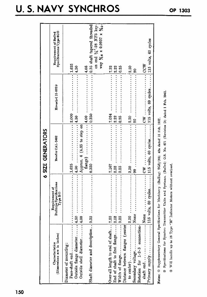
U. S. NAVY SYNCHROS OP 1303
OS
O<LU
LUNCO
•o
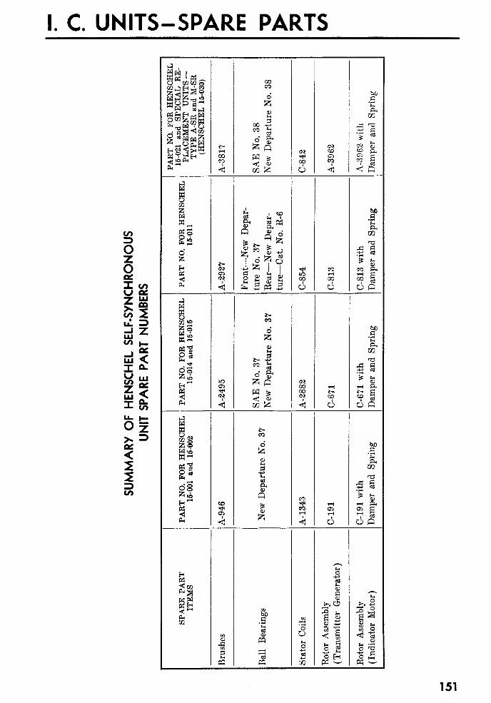
I. C. UNITS-SPARE PARTS
CO
OzoI oo\J ec-T Ui^ °°&2ul =>
CO h_
UI <.I a-
fe fc=Oz>» =<2
CO
J,
U. S. NAVY SYNCHROS op iaos
THE INTERCHANGEABILITY OF BUSHIPS UNITS
REPLACING A BUSHIPS UNIT WITH ANOTHER TYPE BUSHIPS UNIT
Study of these tables will show that Bureau of Ships self-synchronous units of any given type are
interchangeable for most applications as complete units mechanically and electrically regardless of
manufacturer or date of manufacture with the following exceptions:
1. Henschel and Bendix Type N units are electrically interchangeable, but considerably different as
to mounting dimensions.
2. Type A and M units are now supplied with 0.3125 inch diameter shafts instead of 0.250 inch
diameter shafts. When adapting the new type units to instruments formerly equipped with the older
type, the following should be noted:
3. Where a unit with a 0.250 inch diameter shaft was used in connection with a shaft extension
or coupling with thin cross section, the best thing to do is to make a new extension or coupling to
fit the new 0.3125 inch diameter shaft.
4. Where a unit with a 0.250 inch diameter shaft was used in connection with gears, hubs, clamp-
ing nuts, shaft extensions, couplings, pointer hubs, or arrow collars having adequate cross section,
the simplest thing to do is to ream a larger hole to fit the larger shaft. Grinding the 0.3125 inch
diameter shaft to 0.250 inch diameter is not recommended.
5. Some applications of Henschel 15-001 units require a 4-48 screw through the end of the shaft.
Newer Henschel 15-021 units use a 6-40 screw. This applies particularly to the type A unit used in
Pitometer Log Corporation, type B shaft revolution transmitters.
6. The variation in outside shell diameter for type A and M units as listed in the tables is not
serious and does not affect interchangeability for most applications.
7. Adequate spares are normally provided for all Interior Communication units installed on naval
vessels. It is good to know, however, that in an emergency Bureau of Ships units may be interchanged
to the extent indicated in the table. Normally, Bureau of Ordnance Synchros should never be used
to replace Bureau of Ships units.
REPLACING A BUSHIPS UNIT WITH A SYNCHRO
The possibilities of emergency replacement of a Bureau of Ships unit with the corresponding Bureau
of Ordnance Synchro will be made clearer by noting the following differences:
1. Mounting dimensions as shown by the tables are essentially the same for Bureau of Ships units
and corresponding Bureau of Ordnance Synchros, except for Henschel type N units.
2. Shaft diameters and methods of shaft coupling differ considerably as shown. Some form of
adapter must be used in practically all cases.
3. Shaft rotation is opposite for Bureau of Ships units and Bureau of Ordnance Synchros. Also
the primary is on the stator for Bureau of Ships units and on the rotor for Bureau of Ordnance
Synchros. Bureau of Ships units and corresponding Bureau of Ordnance Synchros are electrically
interchangeable provided terminals El, E2, SI, S2, S3, respectively, of Bureau of Ordnance Synchros,
are connected where terminals SI, S2, K3, K2, El, respectively of Bureau of Ships units were.
4. Accuracy of Bureau of Ordnance Synchros is higher than for corresponding Bureau of Ships
units.
5. Bureau of Ships units are equipped with terminal blocks and Bureau of Ordnance Synchros
are not, but this does not affect interchangeability.
152
I. C. UNITS-OBSOLETE TYPES
OBSOLETE TYPES
Obsolete types of Bureau of Ships units not covered by the tables are in general not interchange-
able. Some of the more important variations include the following:
1. Bureau of Ships, types A, B, and M units furnished by Arma Corporation have a higher maxi-
mum secondary voltage (approximately 103 volts) and are, therefore, noninterchangeable elec-
trically with other makes. A few special replacement units have been made up for specific vessels,
but in most cases the original equipment has been completely replaced by new equipment.
2. General Electric units furnished to the Bureau of Ships are not interchangeable mechanically
with other makes. A special stock has been set up at Navy Yard, Mare Island, to cover possible
need for G.E. Model T-3637297 (Type A). G.E. Model T-51E130, T-51E130 (Type B), and G.E.
Model T-3637295 (Type M).
3. Henschel units furnished prior to 1936 have a lower maximum secondary voltage (approxi-
mately 80 volts). They are interchangeable electrically with other makes, although some circulating
current is produced by interconnection with units having 90-volt secondaries. Mounting dimensions
are also different as illustrated by the following data:
ype

U. S. NAVY SYNCHROS op 1303
154
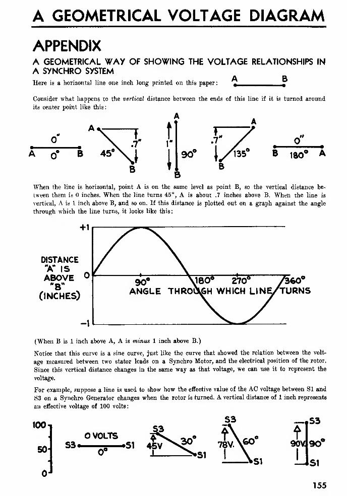
A GEOMETRICAL VOLTAGE DIAGRAM
APPENDIXA GEOMETRICAL WAY OF SHOWING THE VOLTAGE RELATIONSHIPS IN
A SYNCHRO SYSTEMA B
Here is a horizontal line one inch long printed on this paper: t ,
Consider what happens to the vertical distance between the ends of this line if it is turned around
its center point like this:
B
tl1"
l
90"
."
B wWhen the line is horizontal, point A is on the same level as point B, so the vertical distance be-
tween them is inches. When the line turns 45°, A is about .7 inches above B. When the line is
vertical, A is 1 inch above B, and so on. If this distance is plotted out on a graph against the angle
through which the line turns, it looks like this:
DISTANCEX IS ^ABOVE °
(INCHES)
360'TURNS
(When B is 1 inch above A, A is minus 1 inch above B.)
Notice that this curve is a sine curve, just like the curve that showed the relation between the volt-
age measured between two stator leads on a Synchro Motor, and the electrical position of the rotor.
Since this vertical distance changes in the same way as that voltage, we can use it to represent the
voltage.
For example, suppose a line is used to show how the effective value of the AC voltage between SI and
S3 on a Synchro Generator changes when the rotor is turned. A vertical distance of 1 inch represents
an effective voltage of 100 volts:
100
50
J
O VOLTSS3* .51
0°
—,S3A90V 90°
-Jsi
155
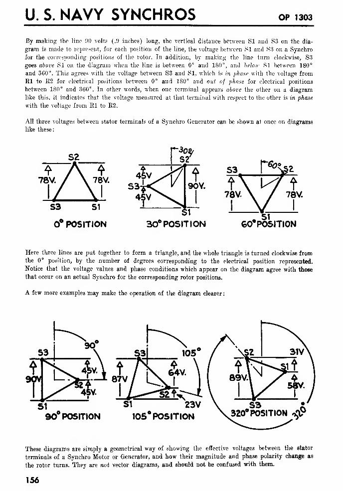
U. S. NAVY SYNCHROS OP 1303
By making the line 90 volts (.9 inches) long, the vertical distance between SI and S3 on the dia-
gram is made to represent, for each position of the line, the voltage between SI and S3 on a Synchro
for the corresponding positions of the rotor. In addition, by making the line turn clockwise, S3
goes above SI on the diagram when the line is between 0° and 180°, and below SI between 180°
and 360°. This agrees with the voltage between S3 and SI, which is in phase with the voltage from
Rl to E2 for electrical positions between 0° and 180° and out of phase for electrical positions
between 180° and 360°. In other words, when one terminal appears above the other on a diagram
like this, it indicates that the voltage measured at that terminal with respect to the other is in phase
with the voltage from Rl to R2.
All three voltages between stator terminals of a Synchro Generator can be shown at once on diagrams
like these
:
S3 S1
0° POSITION
78V
30° POSITION COMPOSITION
Here three lines are put together to form a triangle, and the whole triangle is turned clockwise fromthe 0° position, by the number of degrees corresponding to the electrical position represented.
Notice that the voltage values and phase conditions which appear on the diagram agree with those
that occur on an actual Synchro for the corresponding rotor positions.
A few more examples may make the operation of the diagram clearer
:
90° POSITION
SI 23V105° POSITION
These diagrams are simply a geometrical way of showing the effective voltages between the stator
terminals of a Synchro Motor or Generator, and how their magnitude and phase polarity change as
the rotor turns. They are not vector diagrams, and should not be confused with them.
156
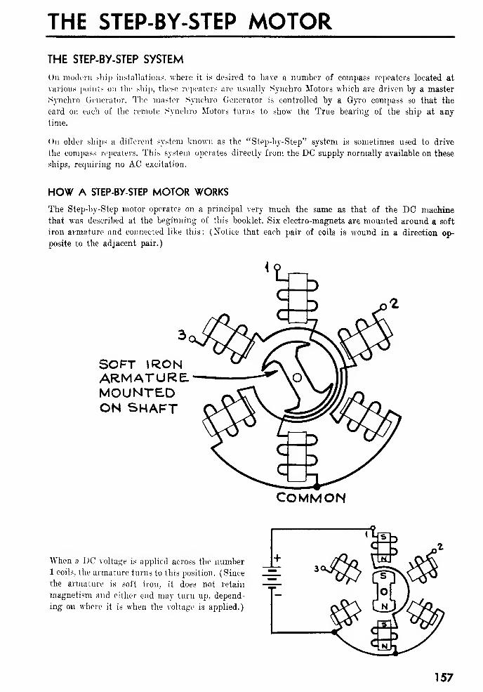
THE STEP-BY-STEP MOTORTHE STEP-BY-STEP SYSTEM
On modern ship installation.-;, where it is desired to have. a number of compass repeaters located at
various points on the ship, these repeaters are usually Synchro Motors which are driven by a master
Synchro Generator. 'The master Synchro Generator is controlled by a Gyro compass so that the
card on each of the remote Synchro Motors turns to show the True bearing of the ship at any
time.
On older ships a different system known as the "Step-by-Step" system is sometimes used to drive
the compass repeaters. This system operates directly from the DC supply normally available on these
ships, requiring no AC excitation.
HOW A STEP-BY-STEP MOTOR WORKS
The Step-by-Step motor operates on a principal very much the same as that of the DC machine
that was described at the beginning of this booklet. Six electro-magnets are mounted around a soft
iron armature and connected like this: (Notice that each pair of coils is wound in a direction op-
posite to the adjacent pair.)
{
SOFT IRONARMATURE.MOUNTEDON SHAFT
COMMON
When a DC voltage is applied across the number1 coils, the armature turns to this position. (Since
the armature is soft iron, it does not retain
magnetism and either end may turn up, depend-
ing on where it is when the voltage is applied.)
157
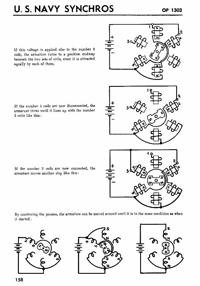
U. S. NAVY SYNCHROS OP 1303
If this voltage is applied also to the number 2
coils, the armature turns to a position midway
between the two sets of coils, since it is attracted
equally by each of them.
If the number 1 coils are now disconnected, the
armature turns until it lines up with the number
2 coils like this:
If the number 3 coils are now connected, the
armature moves another step like this
:
By continuing the process, the armature can be moved around until it is in the same condition as when
it started:
-*^
158
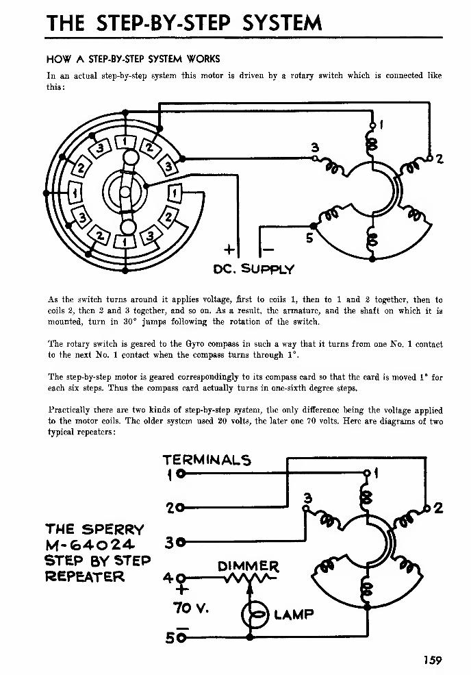
THE STEP-BY-STEP SYSTEM
HOW A STEP-BY-STEP SYSTEM WORKS
In an actual step-by-step system this motor is driven by a rotary switch which is connected like
this:
As the switch turns around it applies voltage, first to coils 1, then to 1 and 2 together, then to
coils 2, then 2 and 3 together, and so on. As a result, the armature, and the shaft on which it is
mounted, turn in 30° jumps following the rotation of the switch.
The rotary switch is geared to the Gyro compass in such a way that it turns from one No. 1 contact
to the next No. 1 contact when the compass turns through 1°.
The step-by-step motor is geared correspondingly to its compass card so that the card is moved 1° for
each six steps. Thus the compass card actually turns in one-sixth degree steps.
Practically there are two kinds of step-by-step system, the only difference being the voltage applied
to the motor coils. The older system used 20 volts, the later one 70 volts. Here are diagrams of two
typical repeaters
:
TERMINALS1*
THE SPERRY
STEP BY STEPREPEATER 40
159

U. S. NAVY SYNCHROS OP 1303
FOR 10 VOLTOPERATION3HORT OUTRESISTORS
<3.E. TYPEMOTOR
DC. RESISTANCE OFEACH PAIR OF COILS15 70il
STANDARD CONNECTIONS IN A STEP-BY-STEP SYSTEM
There are five wires in the standard step-by-step system, numbered like this:
10
20
30
40
50
1CONNECT TO CORRESPONDINGCOILS ON STEP BY STEPMOTOR
-f 70 VOLTS FOR PILOT LAMP— 70 VOLTS AND COIL COMMON
"SETTING ZERO" ON A STEP-BY-STEP REPEATER
If the power supply to a Synchro system is interrupted, and reconnected at a later time, the re-
peaters will always turn automatically when power is reconnected to show the same reading as the
master Synchro. If the DC supply is disconnected from a step-by-step system when the master
compass reads 160° and reconnected after it has changed to 140°, all of the repeaters will still
read 160°, and will read 20° high from then on, until they are corrected.
A hand reset knob is provided on step-by-step repeaters so that the motor may be turned by hand
to agree with the reading on the Master Compass each time the power supply is reconnected.
160
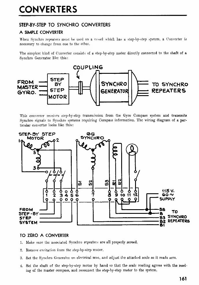
CONVERTERS
STEP-BY-STEP TO SYNCHRO CONVERTERS
A SIMPLE CONVERTER
When Synchro repeaters must be used on a vessel which has a step-by-step system, a Converter is
necessary to change from one to the other.
The simplest kind of Converter consists of a step-by-step motor directly connected to the shaft of a
Svnchro Generator like this:
FROMMASTERGYRO.
SYNCHROGENERATOR!
TO SYNCHROREPEATERS
This converter receives step-by-step transmission from the Gyro Compass system and transmits
Synchro signals to Synchro systems requiring Compass information. The wiring diagram of a par-
ticular converter looks like this
:
STEP- BY STEPMotor
<2>GSYNCHRO
FROMSTEP -BVSTEPSYSTEM
BB
53 SYNCHRO62 REPEATERSB1
TO ZERO A CONVERTER
1. Make sure the associated Synchro repeaters are all properly zeroed.
2. Remove excitation from the step-by-step motor.
3. Set the Synchro Generator on electrical zero, and adjust the attached scale so it reads zero.
4. Set the shaft of the step-by-step motor by hand so that the scale reading agrees with the read-
ing of the master compass, and reconnect the step-by-step motor to the system.
161
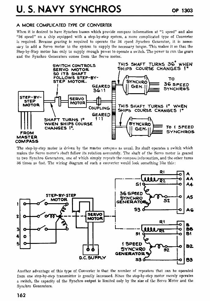
U. S. NAVY SYNCHROS OP 1303
A MORE COMPLICATED TYPE OF CONVERTER
When it is desired to have Synchro busses which provide compass information at "1 speed" and also
"36 speed" on a ship equipped with a step-by-step system, a more complicated type of Converter
is required. Because gearing is required to operate the 36 speed Synchro Generator, it is neces-
sary to add a Servo motor to the system to supply the necessary torque. This makes it so that the
Step-by-Step motor has only to supply enough power to operate a switch. The power to run the gears
and the Synchro Generators comes from the Servo motor.
STEP-BY-STEPMOTOR.
SWITCH CONTROLSSERVO MOTORSO ITS SHAFTFOLLOWS STEP-BY-STEP MOTOR.
I GEARED gJ 36 '• 1 I
THIS SHAFT TURNS 3€> WHENSHIPS COURSE CHANGES 1°
r\Th SERVO
MOTOR #Coupling =
SHAFT TURNS 1°
WHEN SHIPS COURSECHANGES 1°.
GEARED
SYNCHROGEN.
TO36 SPEEDSYNCHROS
THIS SHAFT TURN5 <° WHENSHIPS COURSE CHANGES 1°
SYNCHROGEN TO i SPEED
SYNCHROSFROMMASTERCOMPASSThe step-by-step motor is driven by the master compass as usual. Its shaft operates a switch which
makes the Servo motor's shaft follow its rotation accurately. The shaft of the Servo motor is geared
to two Synchro Generators, one of which simply repeats the compass information, and the other turns
36 times as fast. The wiring diagram of such a converter would look something like this:
Rl
r SK
STEP-BY-STEPMOTOR
O ldI I
SERVOMOTOR
36 SPEEDSYNCHRO
I GENERATE
H
66I
D.C.SUPPLY
i SPEEDSYNCHRO
GENERATOR53
Another advantage of this type of Converter is that the number of repeaters that can be operated
from one step-by-step transmitter is greatly increased. Since the step-by-step motor merely operates
a switch, the capacity of the Synchro output is limited only by the size of the Servo Motor and the
Synchro Generators.
162
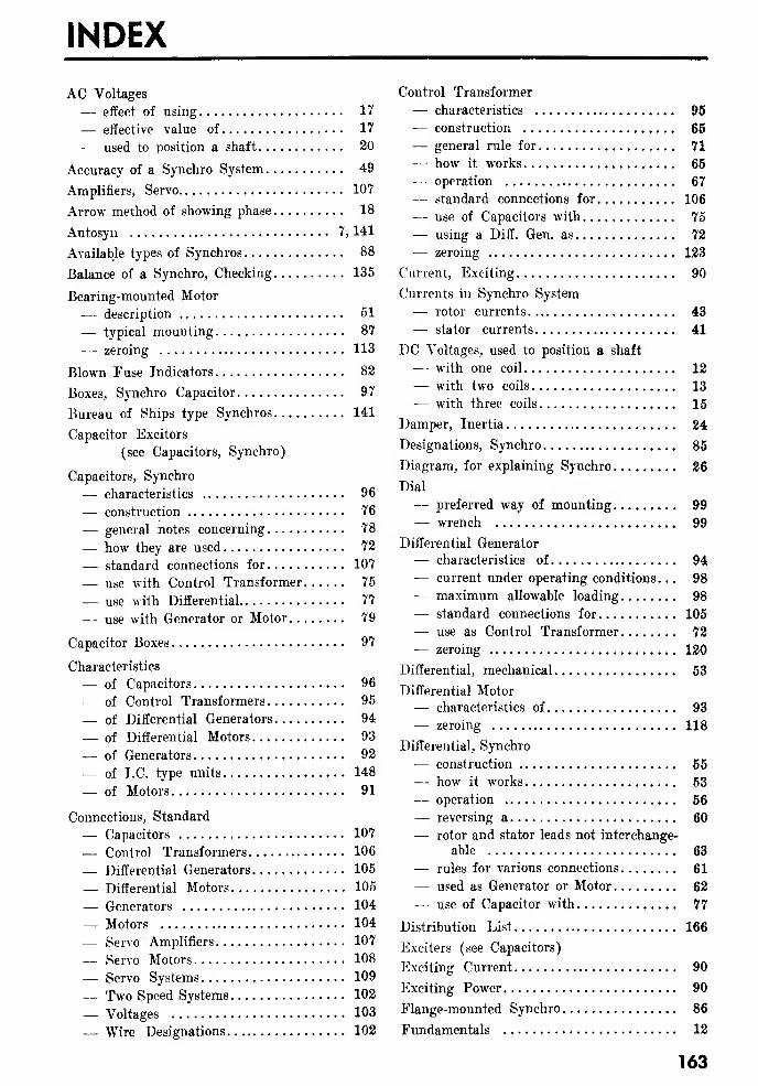
INDEX
AC Voltages
— effect of using 17
— effective value of 17
-— used to position a shaft 20
Accuracy of a Synchro System 49
Amplifiers, Servo 107
Arrow method of showing phase 18
Autosyn 7, 141
Available types of Synchros 88
Balance of a Synchro, Checking 135
Bearing-mounted Motor
— description 51
— typical mounting 87
— zeroing 113
Blown Fuse Indicators 82
Boxes, Synchro Capacitor 97
Bureau of Ships type Synchros 141
Capacitor Excitors
(see Capacitors, Synchro)
Capacitors, Synchro
— characteristics 96
— construction 76
— general notes concerning 78
— how they are used 72
— standard connections for 107
— use with Control Transformer 75
— use with Differential 77
— use with Generator or Motor 79
Capacitor Boxes 97
Characteristics
— of Capacitors 96
— of Control Transformers 95
— of Differential Generators 94
— of Differential Motors 93
— of Generators 92
— of I.C. type units. 148
— of Motors 91
Connections, Standard
— Capacitors 107
— Control Transformers 106
— Differential Generators 105
— Differential Motors 105
— Generators 104
— Motors 104
— Servo Amplifiers 107
— Servo Motors 108
— Servo Systems 109
— Two Speed Systems 102
— Voltages 103
— Wire Designations 102
Control Transformer
— characteristics 95
— construction 65
— general rule for 71
— how it works 65
— operation 67
— standard connections for 106
— use of Capacitors with 75
— using a Diff. Gen. as 72
— zeroing 123
Current, Exciting 90
Currents in Synchro System
— rotor currents 43— stator currents 41
DC Voltages, used to position a shaft
— - with one coil 12
— with two coils 13
— with three coils 15
Damper, Inertia 24
Designations, Synchro 85
Diagram, for explaining Synchro 26
Dial
— preferred way of mounting 99
— wrench 99
Differential Generator
— characteristics of 94
— current under operating conditions. .
.
98
— maximum allowable loading 98
— standard connections for 105
— use as Control Transformer 72
— zeroing 120
Differential, mechanical 53
Differential Motor— characteristics of 93
— zeroing 118
Differential, Synchro
— construction 55
— how it works 53
— operation 56— reversing a 60
— rotor and stator leads not interchange-
able 63
— rules for various connections 61
— used as Generator or Motor 62
— use of Capacitor with 77
Distribution List 166
Exciters (see Capacitors)
Exciting Current 90
Exciting Power 90
Flange-mounted Synchro 86
Fundamentals 12
163
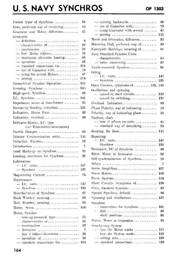
U. S. NAVY SYNCHROS OP 1303
Future types of Synchros 88
Gear, preferred way of mounting 99
Generator and Motor, difference 25
Generator
— definition 8
— characteristics of 92
— construction 22
— how Motor follows 38
— maximum allowable loading 98
— operation 26
— standard connections for 104
— use of Capacitor with 79
— using for several Motors 47
— zeroing 114
Geometrical Synchro Operation 155
Greasing Synchros 125
High-speed Synchros 86
I.C. Synchros 141
Impedance, series of transformer 35
Increasing Heading, definition 101
Indicators, Blown Fuse 82
Indicators, Overload 80
Indicator-Motors, I.C. type
( see Transmitter-Generators)
Inertia Damper 24
Interior Communication units 141
Induction Exciters 72
Introduction 7
Lead Markings on Synchros 25
Loading, maximum for Synchros 98
Lubrication
— I.C. units 147
— Synchros 125
Magnetizing Current 74
Maintenance
- I.C. units 147
— Synchros 125
Manufacturers of Synchros 85
Mark Number, meaning 85
Mod. Number, meaning 85
Motor, Servo 108
Motor, Synchro
— bearing-mounted type 51
— characteristics of 91
— construction 22
— definition 7
— how it follows Generator 38
— operation of 26
— standard connections for 104
164
— turning backwards 50
— use of Capacitor with 79
— using Generator with several 47
— zeroing 112
Motor and Generator, difference 25
Mounting Dial, preferred way of 99
Nameplate Markings, meaning of 85
Navy Standard Synchro Units
— characteristics 85
— notes concerning 97
Nozzle-mounted Synchro 86
Oiling
— I.C. units 147
— Synchros 125
Open Circuits, symptoms of 129, 132
Oscillations and spinning
— caused by short circuits 139
— caused by switching 137
Overload Indicators 80
Phase Polarity, way of indicating 18
Polarity, way of indicating phase 18
Position, shaft
— how it affects currents 41
— standard way of describing 26
Heading, the Zero Ill
Repairing
— I.C. units 147
— Synchros 125
Resistance, DC of Synchros 90
Rotor, Motor or Generator 22
Self-synchronization of Synchros 10
Selsyn 7
Servo Amplifiers 107
Servo Motors 108
Servo Systems 109
Short Circuits, Symptoms of 130
Sizes, standard Synchro 85
Special Synchros, defined 86
Spinning and Oscillations 137
Standard—- connections for' Synchros 101
-- dial."
26
— shaft positions 26
Stat or, Motor or Generator 22
Step-by-step System- - how the Motor works 157
~~ how the System works 159
— setting zero 160
— standard connections 160
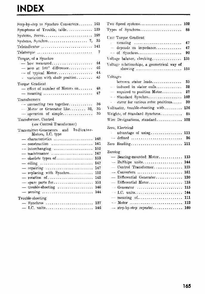
INDEX
Step-by-step to Synchro Converters 161
Symptoms of Trouble, table 129
Systems, Servo 109
Systems, Synchro 7, 35
Teleindicator 141
Teletorque 7
Torque, of a Synchro
— how measured 44
— zero at 180° difference 46
-— of typical Motor 44
— variation with shaft position 45
Torque Gradient
— effect of number of Motors on 48
— meaning 47
Transformers
— connecting two together 36
— Motor or Generator like 32, 35
— operation of simple 35
Transformer, Control
(see Control Transformer)
Transmitter-Generators and Indicator-
Motors, I.C. type
— characteristics 148
— construction 141
— interchanging 152
— maintenance 147
— obsolete types of 153
— oiling 147
— repairing 147
— replacing with Synchro 152
— rotation of 142
— spare parts for 151
— trouble-shooting 146
— zeroing 144
Trouble-shooting
— Synchros 127
— I.C. units 146
Two Speed systems 102
Types of Synchros 88
Unit Torque Gradient
— meaning 47
— depends on impedance 47
-- of Synchros 90
Voltage balance, checking 135
Voltage relationships, a geometrical way of
showing 155
Voltages
— between stator leads 33
— induced in stator coils 32
— required to position Motor 27
— Standard Synchro 103
— stator for various rotor positions 30
Voltmeter, trouble-shooting with 136
Weights, of Standard Synchros 85
Wire Designations, standard 102
Zero, Electrical
— advantage of using Ill
— denned 26
Zero Reading Ill
Zeroing
— Bearing-mounted Motor 113
— BuShips units 144
— Control Transformer 123
— Converters 161
— Differential Generator 120
—- Differential Motor 118
— Generator 115
— I.C. units 144
— meaning of Ill
— Motor 112
— step-by-step repeater 160
165
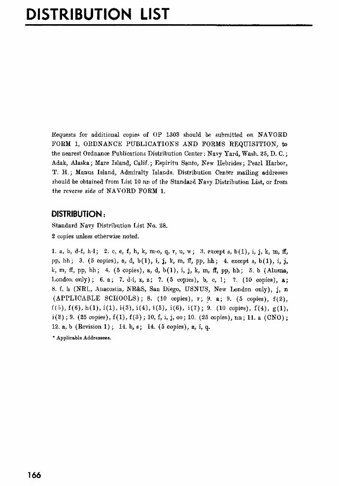
DISTRIBUTION LIST
Requests for additional copies of OP 1303 should be submitted on NAVORDFORM 1, ORDNANCE PUBLICATIONS AND FORMS REQUISITION, to
the nearest Ordnance Publications Distribution Center : Navy Yard, Wash. 25, D. C.
;
Adak, Alaska ; Mare Island, Calif. ; Espiritu Santo, New Hebrides ; Pearl Harbor,
T. H. ; Manus Island, Admiralty Islands. Distribution Center mailing addresses
should be obtained from List 10 nn of the Standard Navy Distribution List, or from
the reverse side of NAVORD FORM 1.
DISTRIBUTION:
Standard Navy Distribution List No. 28.
2 copies unless otherwise noted.
1. a, b, d-f, h-1; 2. c, e, f, h, k, m-o, q, r, u, w; 3. except s, b(l), i, j, k, m, ff,
pp, hh; 3. (5 copies), a, d, b(l), i, j, k, m, ff, pp, hh; 4. except s, b(l), i, j,
k, m, ff, pp, hh; 4. (5 copies), a, d, b(l), i, j, k, m, ff, pp, hh; 5. b (Alusna,
London only); 6. a; 7. d-i, x, z; 7. (5 copies), b, c, 1; 7. (10 copies), a;
8. f, h (NRL, Anacostia, NR&S, San Diego, USNUS, New London only), j, n
(APPLICABLE SCHOOLS); 8. (10 copies), r; 9. a; 9. (5 copies), f(2),
f(5),f(6),h(l),i(l), i(3), i(4),i(5), i(6), i(7); 9. (10 copies), f'(4), g(l),
i(2) ; 9. (25 copies), f (1), f (3) ; 10, f, i, j, oo; 10. (25 copies), nn; 11. a (CNO)
;
12. a, b (Revision 1) ; 14. b, s; 14. (5 copies), a, i, q.
* Applicable Addressees.
166