Embed Size (px)
Citation preview

United States Patent 5,188,738Kaali et al. Feb. 23, 1993
ALTERNATING CURRENT SUPPLIED ELECTRICALLY CONDUCTIVEMETHOD AND SYSTEM FOR TREATMENT OF BLOOD AND/OR OTHERBODY FLUIDS AND/OR SYNTHETIC FLUIDS WITH ELECTRIC FORCES
Inventors: Steven Kaali, Dobbs Ferry, NY 10522Peter M. Schwolsky, Washington, DC 20016
Application Number: 615,437Date Filed: Nov. 16, 1990
International Class: B01D 35/6; A61K 41/00U.S. Class: 210/748; 128/419 R; 128/421; 128/783; 128/784; 204/131;
204/164; 204/186; 204/302; 210/243; 422/22; 422/44; 604/4Field of Search: 210/243; 210/748; 210/764; 128/419 R; 128/421; 128/783;
128/784; 604/4; 422/22; 422/44; 204/131; 204/164; 204/186;204/242; 204/275; 204/302; 204/305
Primary Examiner: Robert A. DawsonAssistant Examiner:Sun Uk Kim
Attorney, Agent, or Firm: Charles W. Helzer
AbstractA new alternating current process and system for treatment of blood and/or other body fluids and/or syntheticfluids from a donor to a recipient or storage receptacle or in a recycling system using novel electricallyconductive treatment vessels for treating blood and/or other body fluids and/or synthetic fluids with electricfield forces of appropriate electric field strength to provide electric current flow through the blood or otherbody fluids at a magnitude that is biologically compatible but is sufficient to render the bacteria, virus,parasites and/or fungus ineffective to infect or affect normally healthy cells while maintaining the biologicalusefulness of the blood or other fluids. For this purpose low voltage alternating current electric potentialsare applied to the treatment vessel which are of the order of from about 0.2 to 12 volts and produce currentflow densities in the blood or other fluids of from one microampere per square millimeter of electrode areaexposed to the fluid being treated to about two milliamperes per square millimeter.
References CitedU.S. PATENT DOCUMENTS592,735 Oct. 1897 Jones672,231 Apr. 1901 Lacomme2,490,730 Dec. 1949 Dubilier
3,692,648 Sep. 1972 Matloff et al.3,753,886 Aug. 1973 Myers3,878,564 Apr. 1975 Yao et al.3,965,008 Jun. 1976 Dawson3,994,799 Nov. 1976 Yao et al.
4,473,449 Sep. 1984 Michaels et al.4,616,640 Oct. 1986 Kaali et al.4,770,167 Sep. 1988 Kaali et al.4,932,421 Jun. 1990 Kaali et al.
5,049,252 Sep. 1991 Murrell5,058,065 Oct. 1991 Slovak
Apr-21-1999 at 16:04 GMT Manning & Napier Information Services http://www.patentminer.comPage 1

United States Patent 5,188,738Kaali et al. Feb. 23, 1993
5,133,932 Jul. 1992 Gunn et al.
NON-U.S. PATENT DOCUMENTS995848 Jul. 1983 Union of Soviet Socialist Republics 210/243
Other PublicationsProceedings of the Society for Experimental Biology & Medicine, vol. 1, (1979), pp. 204-209, "Inactivationof Herpes Simples Virus with Methylene Blue, Light and Electricity"–Mitchell R. Swartz et al.
Journal of the Clinical Investigation published by the American Society for Clinical Investigations, Inc., vol.65, Feb. 1980, pp. 432-438–"Mechanisms of Photodynamic Inactivation of Herpes Simplex Viruses"–LowellE. Schnipper et al.
Journal of Clinical Microbiology, vol. 17, No. 2, Feb. 1983, pp. 374-376, "Photodynamic Inactivation ofPseudorabier Virus with Methylene Blue Dye, Light and Electricity"–Janine A. Badyisk et al.
SummaryThis invention relates to novel electrically conductive methods and systems employing electrically conductivevessels provided with electrically conductive surfaces for use in subjecting blood and/or other body fluidsand/or synthetic fluids such as tissue culture medium to direct treatment by alternating current electric forces.
BACKGROUND PROBLEM
It is now well known in the medical profession and the general public that blood collected in a blood bankfrom a large number of donors may be contaminated by contaminants such as bacteria, virus, parasitesand/or fungus obtained from even a single donor. While screening of donors has done much to alleviate thisproblem, the screening of donors can and does miss occasional donors whose blood is unfit for use. Whenthis occurs and the unfit blood is mixed with otherwise usable blood, the entire batch must be discardedfor transfusion purposes. Because of this problem, the present invention has been devised to attenuate anybacteria, virus (including the AIDS HIV virus) parasites and/or fungus contained in blood contributed by adonor to the point that any such contaminant is rendered ineffective for infecting a normally healthy humancell, but does not make the blood biologically unfit for use in humans. Similar problems exist with respect totreatment of other body fluids, such as amniotic fluids. The treatment method and system is also applicableto mammals other than humans.
In addition to the above, there is a need for methods and systems for the treatment of blood and other bodyfluids both in in-situ processing wherein the treated blood and/or other body fluids are withdrawn from thebody, treated and then returned to the body in a closed loop, recirculating treatment process that is locatednear but outside the patient’s body, or the treatment can be effected through implanted treatment systemcomponents.
In co-pending United States application serial No. 07/615,800 entitled "Electrically Conductive Methods andSystems for Treatment of Blood and Other Body Fluids with Electric Forces"-Steven Kaali and Peter M.Schwolsky, inventors, filed concurrently and co-pending with this application, a similar treatment method andsystem employing direct current excitation potentials is described and claimed. The disclosure of co-pendingapplication Ser. No. 07/615,800 hereby is incorporated into this application in its entirety.
SUMMARY OF INVENTION
The present invention provides new electrically conductive methods and systems using alternating electriccurrent excitation potentials for treating blood and/or other body fluids, such as amniotic fluids, and/or
Apr-21-1999 at 16:04 GMT Manning & Napier Information Services http://www.patentminer.comPage 2

United States Patent 5,188,738Kaali et al. Feb. 23, 1993
synthetic fluids such as tissue culture medium from a donor to a transfusion recipient or to a storagereceptacle, or for recirculating a single donor’s or patient’s blood or other body fluids. The treatment canbe accomplished in a treatment system external of the body or by implant devices for purging contaminantsusing a novel electrically conductive vessel for direct electric treatment of blood or other body fluids,such as amniotic fluids, with alternating current electric field forces of appropriate electric field strengthto attenuate such contaminants to the extent that bacteria, virus, fungus, and/or parasites contained in theblood or other body fluids are rendered ineffective to infect and/or affect normally healthy human cells. Thetreatment, however, does not render the blood or other body fluids biologically unfit for use in humans orother mammals after the treatment. The new methods and systems according to the invention achieve theseends without requiring time consuming and expensive processing procedures and equipment in addition tothose normally required in the handling of blood or other body fluids or synthetic fluids. The invention canbe used to achieve the electric field force treatment during the normally occurring transfer processing froma donor to a recipient or to a collection receptacle, or recirculation of a single donor’s or patient’s blood orother body fluids, such as amniotic fluids.
Drawing Description
BRIEF DESCRIPTION OF DRAWINGS
The above and many other objects, features and attendant advantages of this invention will be appreciatedmore readily as the invention becomes better understood from a reading of the following detailed description,when considered in connection with the accompanying drawings, wherein like parts in each of the severalfigures are identified by the same reference characters, and wherein:
FIG. 1 is a diagrammatic, fragmentary, elevational view of a new blood transfer system using a novelalternating current electrically conductive treatment vessel in the form of conductive tubing to directly treatblood being transferred to a storage receptacle with electric field forces according to the invention;
FIG. 2 is an enlarged, horizontal cross sectional view of the novel electrically conductive tubing treatmentvessel taken across lines 2–2 of FIG. 1;
FIG. 3 is a longitudinal, vertical sectional view of the novel electrically conductive tubing treatment vesseltaken along the staggered section lines 3–3 of FIG. 2;
FIG. 4 is a view similar to FIG. 2 showing a different construction of the novel electrically conductive tubingtreatment vessel;
FIG. 5 is a view similar to FIG. 3, taken along the staggered section lines 5–5 of FIG. 4;
FIG. 6 is a diagrammatic, fragmentary, elevational view showing a different modification of a novel bloodtransfer system using a novel electrically conductive tubing treatment vessel, and which employs a bloodpump and a blood flow regulator;
FIG. 7 is an enlarged cross sectional view, similar to FIG. 2 that shows an electrically conductive tubingtreatment vessel fabricated from longitudinally extending, integrally molded strips of alternate polarity,conductive polymer interconnected by integrally molded, insulating, longitudinally extending strips made ofpolymer or other insulating material;
FIG. 8 is a diagrammatic, fragmentary elevational view showing a different form of a blood transfer systemaccording to the invention wherein a small electrically conductive vessel in the form of a short piece oftubing and a miniaturized battery power source are implanted in the arm of a human being to provide anovel electrically conductive blood and other body fluid treatment system which operates in a closed loop,recirculating manner;
Apr-21-1999 at 16:04 GMT Manning & Napier Information Services http://www.patentminer.comPage 3

United States Patent 5,188,738Kaali et al. Feb. 23, 1993
FIG. 9 is a partial, diagrammatic sectional view of the upper arm portion of a human being and shows ingreater detail the construction of a specially designed miniaturized, electrically conductive treatment vesselwith associated miniaturized battery electric power source and DC to AC power converter for use in theimplant treatment system shown in FIG. 8;
FIG. 10 illustrates the details of construction of a somewhat different form of miniaturized electrifiedtreatment tubing for use in an implanted treatment system of the type shown in FIG. 8 and built accordingto the invention;
FIGS. 11 and 11A illustrate still a different construction for the electrified treatment tubing for use inpracticing the invention wherein the tubing has a square or rectangular cross section with upper and lowerconductive sides and intervening right and left sides separating the two conductive sides made from plastic orother suitable electrical insulating material;
FIG. 12 is a perspective top and side view of a novel electrified, closed, octagonally-shaped, flat, box-liketreatment vessel having an enlarged cross sectional area relative to the cross sectional diameter of the inletand outlet tubes supplying the interior of the treatment vessel;
FIG. 12A is a partial, cross sectional view of the enlarged treatment vessel shown in FIG. 12;
FIG. 13 is a perspective view of a second form of enlarged cross sectional area treatment vessel havingan exterior shape similar to that of FIG. 12, but wherein the electrically conductive electrodes of thetreatment vessel comprise interleaved conductive plates with one set of alternate ones of the plates beingelectrically insulated from the remaining set, and wherein different polarity electric potentials are appliedto the respective sets. If desired, the electrode plates may be formed from an electrically conductive porousmaterial;
FIG. 13A is a partial, cross sectional view taken through the electrically conductive treatment vessel shownin FIG. 13;
FIG. 13B is a sectional view taken through staggered line 13B–13B of FIG. 13A;
FIG. 14 is a longitudinal sectional view of still a different form of enlarged diameter electrified treatmentvessel wherein the vessel is in the form of an elongated cylinder, and the sets of conductive electrodesmounted therein are concentrically arrayed within the interior of the treatment vessel and maintained atdifferent electric potentials;
FIG. 14A is a cross sectional view of FIG. 14 taken through plane A–A;
FIG. 15 is an enlarged longitudinal sectional view of still another form of an enlarged cross sectional areatreatment vessel according to the invention wherein the electrically conductive electrodes of the treatmentvessel are comprised by longitudinally extending needle-like electrodes with alternate ones of the needle-likeelectrodes being provided with opposite polarity electric potentials;
FIG. 15A is a cross sectional view of the treatment vessel shown in FIG. 15 taken through plane A–A ofFIG. 15;
FIG. 16A is a partial cross-sectional view taken through 16A–16A of FIG. 16;
FIG. 16 is a perspective view of still another form of enlarged cross sectional area treatment vessel accordingto the invention wherein the treatment vessel comprises a relatively large block of insulating material havingparallel, longitudinally extending, open ended tubes formed through its length. The tubes are providedwith electrically separated, opposed, parallel extending conductive plate electrodes which have oppositepolarity electric potentials applied thereto. The ends of the tubes open into and are supplied from, or supply,respective reservoirs formed on the respective ends of the central block of insulating material containing thetubes, with inlet and outlet conduits for body fluids to be treated connected to the free ends of the respectivereservoirs;
Apr-21-1999 at 16:04 GMT Manning & Napier Information Services http://www.patentminer.comPage 4

United States Patent 5,188,738Kaali et al. Feb. 23, 1993
FIG. 17 is a perspective view of an enlarged cross sectional area treatment vessel similar to FIG. 16 whereinthe body of the treatment vessel is cylindrical in nature;
FIG. 18 is a diagrammatic, fragmentary elevational view of a human blood or other body fluid treatmentsystem according to the invention employing one of the larger cross sectional dimension fluid treatmentvessels shown in any one of FIGS. 12-16 of the drawings, and which is suitable for use in a continuous flowthrough recirculating body fluid treatment system; and
FIG. 19 is a diagrammatic, fragmentary elevational view of still another human blood or other body fluid,closed loop, recirculating treatment system according to the invention designed for use with the enlargeddiameter fluid treatment vessels illustrated in FIGS. 12-16, and which employs both inlet and outlet fluidpumps on each side of the treatment vessel. With this arrangement the system can be operated in anintermittent manner to allow batch treatment of the body fluids to fully take place before passage of the bodyfluids being treated back to the patient.
Detail Description
BEST MODE OF PRACTICING INVENTION
FIG. 1 is a schematic illustration of one form of a novel blood and other body fluid treatment systemaccording to the invention. FIG. 1 shows an electrically conductive blood and/or other body fluid treatmentvessel constructed according to the invention which is in the form of intravenous tubing 11 interconnectedbetween a hypodermic needle 12 and a blood storage receptacle 14. The needle 12 is inserted in an arteryor vein of the arm 13 of a blood donor and the tubing 11 leads from the arm 13 to the receptacle 14.Alternatively, the system could be set up to transfer blood from the storage receptacle 14 to the arm of arecipient or could be designed to recirculate the blood through electrified tubing 11 back to the donor. Theelectrically conductive tubing 11 may be of any desired length as indicated by the break at 15 so that it canbe appropriately set up to lead from a comfortable position for the donor from whose arm 13 the bloodis being taken to a proper storage location for the receptacle 14. The greater the length of the electrifiedportion of tubing 11, then the more extended is the exposure of the blood (or other body fluid) to the electricfield force effects and low level, biologically compatible current flow through the body fluid being treatedthereby assuring adequate electrification treatment of the fluid without impairing the biological usefulness ofthe blood or other body fluid being treated.
FIG. 2 is a cross sectional view of the electrically conductive tubing 11 taken through plane 2–2 of FIG.1. The tubing 11 may be from 1 to about 20 millimeters in inside diameter, although it may be larger orsmaller in diameter depending upon the intended application. For example, if the blood transfer system is forthe purpose shown in FIG. 6, then the tubing may have a cross sectional dimension of about 5 millimeters.However, if the intended use is in an implanted blood treatment system, such as shown in FIG. 8, then thetubing diameter must be designed to result in a flow-through rate corresponding to the natural circulatoryblood flow rate of the patient in which the system is implanted, and must be long enough to assure effectiveelectrification treatment at the flow rate selected. The tubing 11 is formed from plastic, rubber, medicalgrade polymer, or other suitable material which is compatible with human fluids and/or tissue. A plurality ofphysically separated, electrically conductive surface segments form opposed, parallel electrodes shown at 16and 16A on the inside of tubing 11 from electrically conductive materials such as platinum, platinum alloys,silver, silver or platinum covered alloys, or other similar conductive materials such as conductive polymers,or silver or platinum covered polymers which are compatible with human fluids and tissue. The spacingbetween opposed electrodes 16 and 16A is of the order of 1 to 19 millimeters and perhaps may be more orless dependent upon the application and the conductivity of the body fluids being treated.
FIG. 3 is a longitudinally extending sectional view along the axis of tubing 11 taken through staggeredsection lines 3–3 of FIG. 2. From FIG. 3 of the drawings it will be seen that the electrically conductive
Apr-21-1999 at 16:04 GMT Manning & Napier Information Services http://www.patentminer.comPage 5

United States Patent 5,188,738Kaali et al. Feb. 23, 1993
surface segments 16 and 16A all comprise longitudinally extending, zebra-like stripe or strip electrodeswhich extend longitudinally in parallel with the longitudinal axis of the tubing 11. In between eachlongitudinally extending conductive stripe electrode 16 or 16A is a longitudinally extending electricinsulating area 17 which electrically isolates the alternate electrically conductive, zebra-like stripe electrodes16 and 16A one from the other.
As best shown in FIG. 3, a first set of alternate electrically conductive surface stripes 16 are electricallyconnected in common to a first annular terminal buss 18 which circumferentially surrounds the tubing 11and is embedded within the sidewalls of the tubing 11 at a suitable point along its length. The design issuch that the first annular terminal buss 18 is electrically isolated from the remaining second set of alternate,electrically conductive surface stripe electrodes 16A and is electrically connected through a conductorterminal 19 to an alternating current source of electric excitation potential. AC source 20 may comprise theoutput from an AC to AC voltage converter for converting 110 volt AC potential to the desired 0.2 voltsto 12 volts for use in the invention. For those treatment systems which are to be implanted as describedhereafter, the AC source may comprise a miniaturized DC to AC converter for converting the DC voltagefrom a miniaturized battery to low voltage (0.2 to 12 volts) AC. As best depicted in FIG. 2, all of the firstset of positive electrically conductive stripes 16 are physically and electrically connected in common to thefirst annular terminal buss 18 so that all of the conductive stripes 16 are maintained at a constant, alternatingcurrent electric excitation potential.
A second annular terminal buss 21, which circumferentially surrounds the tubing 11, is embedded within thetubing 11 at a point along its length displaced from the position of the first annular terminal buss 18 andis spaced inwardly towards the inside diameter of the tubing relative to the first annular buss 18. By thisarrangement it is possible to electrically connect the remaining second set of alternate electrically conductivesurface stripes 16A in common to the second annular terminal buss 21 in a manner such that the secondannular terminal buss is electrically isolated from the first annular terminal buss 18 as well as the first setof alternate electrically conductive surface stripes 16. As shown in FIG. 3, the second annular terminal buss21 is provided with an outside terminal conductor connection 22 for connecting the annular buss 21 andannular buss 18 across AC source 20 as shown in the system drawing of FIG. 1. The second set of alternateelectrically conductive surface stripes 16A are all provided with internal connector studs which physicallyand electrically connect all of the 16A stripes in common to the second annular terminal buss 21 so that allof these conductive stripes will be maintained at a potential opposite to that from the potential applied to thefirst set of electrically conductive stripes 16 by annular buss 18.
As described earlier, the AC source of electric potential 20 may constitute an AC to AC converter forconverting 110 volt AC to 0.2 to 12 volt AC or a DC to AC converter for converting 12 volt DC to 0.2 to12 volt AC. The AC source 20 is connected to the conductor terminals 19 and 22 through electric supplyconductors 23 and 24 preferably by a double pole, double throw, on-off control switch 25. In preferredembodiments of the invention, voltage controlling variable resistors 26 and 27 also are included in theelectric supply conductors 23 and 24 in order to control the value of the excitation voltage developedbetween the alternate sets of conductive surface stripes 16, 16A.
In operation, the donor whose blood is to be taken, or the recipient who is to be given blood, or is tohave his or her blood recycled, is made comfortable on a cot with his or her arm 13 extended and theinterconnecting electrically conductive tubing 11 having the hypodermic needle 12 for withdrawal, orsupplying, or recycling of blood set up as shown in FIG. 1. When both the donor/recipient and the systemis in readiness, the control switch 25 is closed so that an electric field is built up across the oppositelydisposed electrically conductive zebra-like stripes 16, 16A, etc. Voltages of the order of from 0.2 to 12 voltsare applied to the conductive surfaces 16, 16A For this purpose it is important to note that the hypodermicneedle should be electrically isolated via conventional electrically insulating IV tubing from any of the zebrastripe electrodes 16, 16A so that the donor/recipient does not receive a shock. By this precaution, he or shewill not even be aware of the existence of the electric field within the electrically conductive tubing 11. With
Apr-21-1999 at 16:04 GMT Manning & Napier Information Services http://www.patentminer.comPage 6
United States Patent 5,188,738Kaali et al. Feb. 23, 1993
the treatment system thus conditioned, the hypodermic needle is inserted into a vein in the donor’s/recipient’sarm and blood is withdrawn, given, or recycled through the tubing 11.
As the blood passes through the electric fields produced within the electric conductive tubing 11 it will besubjected to and treated by biologically compatible electric current flow through the blood or other bodyfluid with a current density of from one microampere per square millimeter (1 A/mm ) of electrode crosssectional area exposed to the fluid to about two milliamperes per square millimeter (2 mA/mm ) dependentupon field strength of the electric field gradient existing between electrodes 16 and 16A, the space betweenthe electrodes 16, 16A and the conductivity (resistivity) of the body fluid being treated. Recent experimentshave proven that exposure to electric fields induced by supply voltages in the range produces electric currentflow through blood of the order of 1 to 100 microamperes. Effectiveness is dependent upon length of timeof treatment in conjunction with the magnitude of the biologically compatible current flow. For example,treatment of virus in media at 100 microamperes for 3 minutes has been observed to substantially attenuate(render ineffective) the AIDS virus. Similar treatment at other field strength values and lengths of timewill have a similar attenuating effect on bacteria, virus, parasites and/or fungus which are present in bloodor other body fluids being treated. By controlling the length of time and field strength values that blood issubjected to the electric field forces, undesirable contaminants such as virus, bacteria, fungus and/or parasiteswill be adequately attenuated to the point that they are rendered ineffective by the sustained action of theelectric current flow as the blood travels from the hypodermic needle 12 to the storage bag 14, or vice versa,or in a recycling mode. The length of travel of the blood through the sustained electric field induced currentflow also can be adjusted so that the blood is subjected to the electric field force for time periods of theorder of from one to six minutes at least. At the current values noted above this is believed adequate toattenuate (render ineffective) bacteria, virus (including the AIDS virus), parasites and/or fungus entrainedin blood or other body fluids, but does not render the fluids unfit for human use or impair their biologicalusefulness.
The species of the invention shown in FIGS. 2 and 3 is advantageous since it is possible to fabricate thetreatment tubing by preforming the conductive segments 16 and 16A on the tubing walls while it is in aflat planar condition, and then rolling the walls into tubular form using a suitable mandrel. The adjoininglongitudinal edges of the planar member after rolling are thereafter heat sealed along a longitudinallyextending seam located within one of the electrically insulating sections 17. Particular attention must be paidto the juncture of the ends of the annular terminal busses 18 and 21 during the rolling and heat sealing stepsto assure that good electrical interconnection and continuity at these junctures of the annular terminal bussesis provided in the completed treatment tubing. The conductive electrode segments 16, 16A may be electro-deposited, chemically formed, separately formed conductive polymer surfaces, or conductive foil or wiresadhesively secured to the side walls of the tubing 11 in advance of the rolling and sealing using techniqueswell known in the printed circuit and integrated circuit manufacturing technologies.
FIG. 6 is a diagrammatic, fragmentary, elevational view of a modified blood treatment system using thenovel electrically conductive treatment tubing in accordance with the invention. In the FIG. 6 embodimentof the invention, a blood pump 28 of conventional, commercially available construction is inserted in thetubing 11 at some point along its length. The blood pump 28 is electrically isolated from the zebra stripedconductive surfaces 16, 16A by suitable insulators 29 formed on the blood input-output connections of pump28. Provision for electrically bypassing the blood pump 28 (if need be) is made through the shunt conductors30, 30A which maintain electrical continuity of the alternating current excitation potential applied to theconductive stripes 16, 16A on each side of pump 28. For convenience, the alternating current excitationsource 20 and its connection to the electrically conductive tubing 11 has not been shown in FIG. 6 but wouldhave to be provided. A separate source of excitation current for running the blood pump 28 is provided froma conventional 110 volt alternating current source through the input terminals 31, 31A.
In systems employing a blood pump, it may be desirable in some applications to provide a blood flowregulating valve 37 inserted in the system at the output of blood pump 28 and within the by-pass loop 30,30A for the conductive stripes 16, 16A. By thus controlling blood flow, the electrified transfer system safely
Apr-21-1999 at 16:04 GMT Manning & Napier Information Services http://www.patentminer.comPage 7

United States Patent 5,188,738Kaali et al. Feb. 23, 1993
can be employed in a closed loop recycling system for withdrawing blood from a patient, electrically treatingthe blood as described above and then returning the electrically treated blood to the patient. This procedureis referred to herein as recycling. The system of FIG. 6 also can be used in those situations where the bloodflow of a donor’s blood is not sufficient to assure supply of an adequate amount of blood to or from thecollection receptacle 14 or other recipient. It may also be desirable to have a blood flow regulating valvesuch as 37 in non-pump systems.
FIGS. 4 and 5 of the drawings show another embodiment of the invention wherein the electrically conductivetreatment tubing 11 includes electrically conductive electrode segments 32 and 32A which are in the form ofzebra stripes that extend radially around the inside diameter of tubing 11 in spaced-apart, alternating polarity,conductive annular bands 32 and 32A separated by insulating surface bands 11I which serve to electricallyisolate the respective first set of conductive zebra stripes 32 from the second set of conductive zebra stripes32A. The first set of alternate ones of the electrically conductive annular stripes 32 are electrically connectedin common to a first longitudinally extending terminal buss bar 33 that is embedded within tubing 11 inparallel with the longitudinal axis of the tubing and electrically isolated from the remaining second set ofalternate electrically conductive annular stripes 32A. The first longitudinally extending terminal buss bar33 is designed for connection to one output terminal of a source, such as 20, of alternating current electricexcitation potential through a supply conductor connection 35 on the exterior surface of the tubing 11.
A second longitudinally extending terminal buss bar 34 is embedded within the body of tubing 11 and iselectrically connected to the remaining second set of alternate electrically conductive annular stripes 32A.The second longitudinally extending terminal buss bar 34 is electrically isolated from the first longitudinallyextending terminal buss 33 and the first set of alternate electrically annular stripes 32. Terminal buss bar 33is designed for connection to a second output terminal for the alternating current source of electric excitationpotential. For this purpose an input supply conductor connection 36 is directly connected through the exteriorsurface of tubing 11 and to the second longitudinally treatment extending terminal buss bar 34.
In operation, the embodiment of the invention shown in FIGS. 4 and 5 is physically arranged in a bloodtreatment system in the manner illustrated in FIG. 1 of the drawings with the positive polarity and negativepolarity zebra annular stripes being connected to the respective output terminals of AC source 20 via controlswitch 25. If required, a blood pump such as 28 and blood flow regulating valve 37 shown in FIG. 6 can beincluded in the blood transfer system employing electrified tubing as shown in FIGS. 4 and 5.
Similar to the system shown in FIG. 1, a blood transfer system employing the embodiment of the inventionshown in FIGS. 4 and 5 would be electrically excited in advance of injection of the hypodermic needle 12into the arm of a blood donor so that all blood passing through the tubing 11 will be subjected to electricforces produced between the alternate polarity annularly formed conductive bands 32 and 32A. Experiencewith the invention will establish what length is required for the electrification field. However, for initialinstallations the length of the electrified field as related to the flow of blood through electrified tubing 11should correspond to at least the 1-6 minute treatment time mentioned earlier. This is achieved by usingan extended array of the alternate annular zebra bands 32 and 32A of adequate length to assure thoroughsubjection of blood to electric current flow produced between the alternating polarity zebra stripes 32 and32A. The electric field force intensity applied to the blood by means of the electrified tubing is anticipated tobe of the order of from 0.2 to 12 volts similar to the embodiment of the invention shown in FIGS. 1-3.
In place of supplying continuous alternating current excitation to the conductive stripes 16, 16A of FIGS.2 and 3 or 32, 32A of FIGS. 4 and 5, it also is possible to excite these electrically conductive segmentsof tubing 11 with pulsed waveform direct current excitation potentials. For use in this manner, the pulserate of the pulsed waveform excitation potentials must be sufficiently high to maintain continuous currentflow through blood being treated. In addition, it may be desirable to couple a bank of storage capacitors inparallel across respective pairs of opposite polarity electrically conductive segments 16, 16A and 32, 32Awhere operation in a pulsed DC mode is desired.
Apr-21-1999 at 16:04 GMT Manning & Napier Information Services http://www.patentminer.comPage 8

United States Patent 5,188,738Kaali et al. Feb. 23, 1993
FIG. 7 of the drawings is a cross sectional view of another embodiment of the invention which issubstantially different from those previously described. In FIG. 7, the material used for fabrication of thetubing 11 is one of the new space-age polymer materials which can be either highly electrically conductive,insulating, or semiconducting and may have values of conductivity ranging from essentially fully conductiveto insulating. In the embodiment of the invention of FIG. 7, the conductive surface areas on the insidediameter of the tubing 11 are actually formed into segments, such as 11C, of the cross sectional area of thetubing 11 fabricated from the highly conductive polymer material. The intervening segments of the tubing11I which separate the conductive segments 11C are integrally formed from the highly insulating polymermaterial. Suitable positive polarity and negative polarity potentials are applied to the exterior surface areasof alternate ones of the sets of conductive polymer segments 11C from a source of electric potential via theconductors 23 and 24 as illustrated schematically in FIG. 7.
It will be appreciated that the embodiment of the invention shown in FIG. 7 is much simpler and henceless expensive to make in that it requires fewer processing steps than the embodiments of the inventionshown in FIGS. 1-6. In other respects, the embodiment of the invention shown in FIG. 7 would be used ina blood transfer system similar to that shown in FIG. 1 or 6 with or without a blood pump 28 and bloodflow regulating valve 37 to effect transfer of blood from a donor to a receptacle or recipient in the eventof a transfusion or recycling. During the blood transfer process, again it would be necessary to providealternating current excitation potentials across the spaced-apart, alternate sets of electrically conductivepolymer segments 11C prior to passing blood through the tubing 11. This will assure that all of the bloodbeing transferred is subjected to the electric field forces produced between the alternate conductive surfaces11C. As a variation of the FIG. 7 embodiment, which visualizes that the segments 11C and 11I all extendlongitudinally and parallel to the longitudinal axis of tubing 11, it would be possible, but more elaborate todesign, to employ alternate radially surrounding annular conductive segments 11C and interlacing insulatingsegments 11I similar to FIG. 5, but such fabrication would require somewhat more complex terminal buss barelectric supply connections 23 and 24 than those shown in FIG. 7.
FIG. 8 is a fragmentary, diagrammatic, elevational view showing a form of blood treatment system accordingto the invention wherein a small electrically conductive vessel 41 in the form of a short piece of electrifiedtubing and a combined miniaturized DC to AC converter and battery power source 42 are implanted in thearm of a human being. The electrified tubing 41 may be in the form of any of the prior disclosed electrifiedtubing structures described with relation to FIGS. 1-7, but which are fabricated in miniaturized form so thatthe tubing 41 and power package 42 can be inserted in a section of or surrounding a vein 44 of the arm13 of a patient whose blood is being treated. The implantation is such that the blood through the patient’svein 44 naturally is pumped through the short piece of electrified tubing 41 while circulating blood to thehand of the patient to thereby form a closed loop, recirculating, implanted treatment system that comprisesan integral part of the circulatory system of the patient being treated. Because the parameters of such animplanted system are necessarily small, a single passage through the implanted electrified tube 14 mayaccomplish relatively little attenuation of contaminants in the blood. Therefore, it is the repeated passageof small portions of the patient’s blood continuously twenty-four hours a day and for as many days as areneeded which will gradually attenuate the contaminants to the point where they are rendered ineffective asdescribed earlier.
FIG. 9 is a partial, fragmentary, sectional view of the upper arm portion 13 of a vein or artery of a patientin which a treatment system according to the invention has been implanted, and shows in greater detailthe construction of a specialized, miniaturized, electrically conductive treatment vessel with associatedminiaturized battery electric power source and DC to AC converter for use in an implanted treatment systemas shown in FIG. 8. In FIG. 9, the electrified vessel 41 is in the form of an outer housing 45 that is in theshape of a football which is implanted within the interior walls 44 of an artery or a vein. The outer housing45 is comprised by a central, cylindrically-shaped portion 45M of solid conductor such as platinum which isbiocompatible with human blood and tissue and has integrally formed, conically-shaped porous ends 45Cwhich are attached to and form an electrically conductive screen grid (at the same potential) as the mid
Apr-21-1999 at 16:04 GMT Manning & Napier Information Services http://www.patentminer.comPage 9

United States Patent 5,188,738Kaali et al. Feb. 23, 1993
portion 45M. The conical end portions 45C both are perforated and may be in the nature of a screen or meshwire and of the same material composition as the mid portion 45M. Disposed within the outer housing 45is a inner housing 46 which is tear-drop shaped and secured within the central portion 45M of the outerhousing by suitable insulating support spider legs 47. The inner housing 46 likewise is formed from platinumor other suitable biocompatible conductive material and has supported within its interior a miniaturized ACsource comprising a miniaturized battery and AC to DC converter 42 secured to the conductive walls ofinner housing 46 by conductive support legs 48. The support legs 48 serve as terminal connectors from oneterminal of AC power converter 42 to the inner housing 46 so that it is maintained at one polarity excitationpotential. The remaining opposite polarity terminal of miniaturized AC source 42 is connected through aninsulated conductor 49 to the central portion 45M of outer housing 45 whereby the entire outer housingincluding the meshed conical end portions 45C are maintained at an opposite polarity potential from theinner housing 46.
Prior to implantation in a patient, the electrified vessel shown in FIG. 9 is activated by connection to ACsource 42 so that an electric field gradient is produced across the space between the inner and outer housings45 and 46. Following implantation of the activated, electrified treatment vessel 41, its presence in a vein orartery will cause all blood flowing through the vein or artery to pass between the side walls of the inner andouter housings 45 and 46 so as to be subjected to the electric field force gradient existing in these spaces.The presence of the electric field forces will induce a current flow through the blood passing between theinterior and outer housings as explained above which will result in attenuating bacteria, virus, parasitesand/or fungus which are present in the blood as contaminants. Here again, because of the relatively smallportion of the total blood flowing in a patient that will be treated by the device within a given time period,it is the repeated, recycling process treatment of the blood over a prolonged period of time that will result inattenuation of the contaminants in the blood to the point where such contaminants are rendered ineffective asdescribed earlier.
In order to further assure adequate treatment of the blood of a patient receiving the implant device, it isrecommended that the blood be treated in an external treatment processing facility such as described earlierin FIGS. 1 and 6 or to be described hereinafter with relation to FIGS. 18 and 19 in which the total capacityof the treatment system is greater whereby substantial attenuation effect can be achieved in a comparativelyshorter time period yet to be determined, and then the in vitro implant treatment system such as shown inFIGS. 8, 9 and 10 can be used to maintain the attenuated condition and to prevent any subsequent build upof contaminants after the initial treatment, if determined to be desirable.
FIG. 10 is a fragmentary, diagrammatic view of a partial vein or artery 44 showing in greater detail thecylindrical or tubular electrified treatment vessel 41 originally described with relation to FIG. 8. This implanttreatment vessel 41 is miniaturized so that it is in effect an open-ended cylinder in shape and has a diametercomparable to that of a large vein or artery and so that it can be grafted or implanted into the vein or arteryas illustrated in FIG. 10. The tubular treatment vessel 41 may be designed pursuant to FIGS. 2 and 3 ofthe drawings, for example. For this application, the battery source of power and interconnected DC toAC converter 42 are annular in shape and are slipped over the tubular treatment vessel 41 in the mannershown. In FIG. 10 a longitudinal sectional view of the hollow annular-shaped treatment vessel 41 and ACpower source 42 is illustrated. At the point where the battery driven AC power source 42 fits over thetubular treatment vessel 41, the respective terminals of the AC power source 42 are exposed to engage thecorresponding positive and negative supply terminals 19 and 22 of the tube 41 so that the resulting structurehas a minimum exterior profile to facilitate implantation. From a comparison of FIG. 10 to FIG. 9 of thedrawings, it will be appreciated that the FIG. 9 treatment vessel introduces some flow restriction in the veinor artery in which it is implanted and for this reason the construction shown in FIG. 10 is preferred.
FIGS. 11 and 11A of the drawings illustrate a construction for the electrified treatment vessel 51 whereinthe treatment vessel is in the form of square or rectangular cross sectionally-shaped open-ended tubing.The treatment tubing 51 provided with a square or rectangular shape so that provision of opposed, parallelconductive electrode surfaces 51U and 51L is greatly simplified as best seen in FIG. 11A of the drawings,
Apr-21-1999 at 16:04 GMT Manning & Napier Information Services http://www.patentminer.comPage 10

United States Patent 5,188,738Kaali et al. Feb. 23, 1993
which is a cross sectional view taken through plane 11A–11A of FIG. 11. By fabricating the upper andlower surfaces of the tubing 11 from electrically conductive material such as platinum, etc., and separatingthe upper and lower surfaces 51U and 51L by electrically insulating side walls 52R and 52L, provision ofthe electrically isolated, opposed, parallel electrode surfaces is simplified and the resulting treatment vesselintroduces minimum restriction to flow of blood. By connecting the upper surface 51U to one terminal ofthe AC power source 42 and connecting the lower surface 51L to the opposite terminal, AC electrificationof the interior area of the tubing wherein the fluids to be treated flow is readily achieved with a greatlysimplified electrode structure. Variations of this structural feature wherein the side insulating surfaces 52Rand 52L are curved with their concave surfaces facing each other and the cross sectional area of the upperand lower conductive surfaces 51U and 51L tailored to provide a desired current density, tubular treatmentvessels such as shown in FIGS. 11 and 11A could be readily provided for use in implantation devices suchas that illustrated in FIG. 8.
FIG. 12 is a perspective view of a novel, electrified, closed, octagonally-shaped, flat, box-like treatmentvessel 60 according to the invention which provides an enlarged cross-sectional area relative to the crosssectional diameter of the inlet and outlet tubing supplying the interior of the treatment vessel wherebyincreased through-put of a fluid being treated can be achieved in a given time period. The treatment vessel60 shown in FIG. 12 is comprised essentially of upper and lower, octagonally-shaped, flat insulating plates61 and 62, respectively, of an insulating material which is compatible with human blood and/or other bodyfluids. Disposed immediately below and above the upper and lower plates 61 and 62 are octagonally-shaped,conductive electrode members 63 and 64, respectively, which are separated and electrically isolated one fromthe other by a surrounding electric insulating gasket member 65. The entire structure is sandwiched togetherand held in assembled relation by threaded thru-pins 66 as best seen in FIG. 12A of the drawings. Theinsulating gasket 65 which may be of teflon defines an open space 67 between the two conductive electrodemembers 63 and 64 into which the blood or other body fluid to be treated is introduced via inlet and outletconduits 68 and 69. Alternating current electric potentials are applied across the respective conductive plates63 and 64 to produce an electric field force across the intermediate space 67 through which the fluids beingtreated flow between electrode plates 63 and 64. By thus structuring the treatment vessel, increased treatmentsurface area is provided to the blood or other body fluid flowing through the space 67 whereby in a giventime period an increased quantity of fluids can be treated.
FIG. 13 is a perspective view of another form of enlarged cross sectional area treatment vessel 70 havingan exterior shape similar to that of the treatment vessel shown in FIG. 12. The electrified treatment vesselshown in FIG. 13 differs from that in FIG. 12, however, in the construction of its electrically conductiveelectrodes which comprise a plurality of interleaved, conductive, flat, electrode plates 71 and 71A. Theelectrode plates 71 are secured in and project inwardly from a right hand (RH) conductive end plate 73R asshown in FIG. 13A. The alternate set of flat electrode plates 71A are secured to and project inwardly froma corresponding conductive end plate 73L on the left hand end of the treatment vessel 70. The conductiveend plates 73R and 73L and coacting insulating side plates 72 which insulate the conducting end plates fromone another, form an octagonally-shaped box frame which is closed by upper and lower insulating top andbottom insulating plates 74 and 75. The conductive end plates 73R and 73L have a central opening formedtherein into which inlet and outlet tubes 76 and 77 are secured as best seen in FIG. 13 for providing inletand outlet flow through connection to the treatment vessel 70.
The alternate sets of flat electrode plates 71 and 71A extend parallel to one another and are provided withalternating current electric potentials supplied across the respective sets of interleaved electrode plates via therespective conductive end members 73R and 73L. If desired, the respective flat conductive electrode plates 71and 71A may be fabricated from a perforated material as shown in FIG. 13B of the drawings. Also, it maybe desirable that some form of thermal insulation, or a thermally controlled chamber be provided around theexterior of the treatment vessel 70 as indicated by the thermal insulation 78 shown in FIG. 13A.
In operation, electrified treatment vessel 70 shown in FIGS. 13, 13A and 13B functions in essentially thesame manner as was described earlier with respect to FIGS. 1-7 to effect attenuation of contaminants such
Apr-21-1999 at 16:04 GMT Manning & Napier Information Services http://www.patentminer.comPage 11
United States Patent 5,188,738Kaali et al. Feb. 23, 1993
as bacteria, virus and fungus contained in blood and/or other body fluids being treated in the flow throughtreatment vessel of FIG. 13.
FIG. 14 is a longitudinal sectional view of still another form of enlarged cross sectional area, electrifiedtreatment vessel 80. The treatment vessel 80 shown in FIG. 14 is in the form of an open-ended, elongatedcylinder 81 whose cylindrical walls are fabricated from an insulating material which is biocompatible withhuman blood and/or other body fluids and whose open ends are closed by circular-shaped conductive endpieces 82 and 83. Inlet and outlet tubular openings 84 and 85 are provided to the interior of cylindricalhousing 81 through centrally formed apertures in the circular end plates 82 and 83. Within the interior of thecylindrical, insulating housing 81 at least two, separate, concentric, perforated, cylindrically-shaped electrodemembers 86 and 87 are provided which extend longitudinally through the interior of the outer cylindricalhousing 81. The first set of concentric, perforated, electrically conductive electrodes 86 is embedded inand supported by the conductive end plate 82 which serves as an electrical terminal for applying electricpotentials to all of the concentric electrode member 86. Similarly, the concentric, perforated, conductiveelectrode member 87 is physically supported by and electrically connected to the conductive end plate 83for the supply of alternating current potentials thereacross. Additionally, if desired, one or more additionalperforated concentric electrode members similar to 86 may be spaced apart from the inner concentricelectrode member 86 outwardly along the diameter of the circular end member 82 with additional perforatedconcentric electrode members 87 being sandwiched between the two electrode members 86 and spacedapart therefrom so as to provide an electric field force between all the spaced apart, separated electricallyconductive electrode members 86 and 87. Additionally, if desired, a conductive surface 89 may be formedaround the interior walls of the outer, insulating cylindrical housing member 81 and electrically connected tothe conductive end plate 82 or 83. This will assure that the entire interior of the treatment 80 vessel crosssectional area is crossed by the electric field force and all blood or other body fluid passing the cylindricalhousing member 81 is subjected to biologically compatible low electric current flow as a consequence of thealternating current electric fields produced between the different concentric electrode members including thecoated surface 89 within the interior insulating housing member 81.
In operation, the embodiment of the invention shown in FIG. 14 and 14A operates in substantially thesame manner as described with relation to earlier embodiments of the invention to assure production ofbiologically compatible electric current flow through the blood or other body fluid being treated in thetreatment vessel 80.
FIG. 15 is a longitudinal sectional view of still another embodiment of an enlarged cross-sectional areatreatment vessel 90. The treatment vessel 90 again comprises an outer, hollow, open-ended cylindrically-shaped, insulating body member 91 whose open ends are closed by electrically conductive, circular endplates 92 and 93, respectively. Inlet and outlet tubular openings 94 and 95 are provided through the centralaxial opening in the conductive end plates 92 and 93 for passage of blood and/or other body fluids beingtreated into the interior of the treatment vessel 90. The conductive end plates 92 and 93 have respective setsof opposite polarity potential needle-like electrodes 96 and 97, respectively, projecting therefrom inwardlyinto the interior of the treatment vessel 90. Alternating current electric potentials are applied to the respectiveconductive end plates 92 and 93 through respective AC supply terminals indicated at 98 and 99. If desired,and in order to assure complete saturation of the entire volumetric area within treatment vessel 90 withelectric fields, a conductive coating similar to that shown at 89 in FIG. 14 can be provided to the innersurface of the hollow, cylindrically-shaped outer body member 91 of treatment vessel 90.
FIG. 15A is a cross sectional view taken through plane A-A of FIG. 15 and shows how the array of needle-like electrodes appear within the interior of the treatment vessel 90. In operation, the treatment vessel 90 willfunction in substantially the same manner as has been described previously with relation to earlier describedembodiments of the invention.
FIG. 16 is a perspective view of still another form of enlarged cross sectional area treatment vessel 100according to the invention and FIG. 16A is a partial cross sectional view taken through plane 16A–16A of
Apr-21-1999 at 16:04 GMT Manning & Napier Information Services http://www.patentminer.comPage 12
United States Patent 5,188,738Kaali et al. Feb. 23, 1993
FIG. 16. The treatment vessel 100 comprises a relatively large rectangular-shaped block 101 of electricalinsulating material which is biocompatible with blood and/or other human body fluids. The insulating block101 has a plurality of parallel, longitudinally extending, open-ended, tubular-shaped openings 102 formedtherein through the entire length of the block. The tubes 102 are provided with electrically isolated, opposed,parallel extending conductive plate electrodes 109 as best shown in FIG. 16A, which have alternatingcurrent electric potentials applied thereacross. One set of these electrodes, formed for example by the lowerelectrode 109 in each tube, extend out to and engage a conductive surface coating formed on one end ofthe insulating block, for example 101R, and the remaining upper electrodes 109 form a second set whichextend out of the left hand end of the tubes and contact a conductive coating formed on the remaining end101L of block 101. Alternating current electric potentials are connected across the respective conductivesurfaces 101R and 101L so that a potential difference exists between the sets of electrodes 109 within eachlongitudinally extending tube in block 101. The ends of the tubes 102 open into and are supplied from, orsupply, respective header reservoirs 103 and 104 formed on the respective opposite ends of the block ofinsulating material 101. Each of the reservoirs 103 and 104 has a centrally formed opening for receivingeither an inlet tube 105 applied to header 103 or an outlet tube 106 secured to header 104 for supply ofblood or other body fluids to be treated to and from the treatment vessel 100. If desired, a blood pump orother fluid pump can be inserted between the supply tube 105 and header 103, or between outlet tube 106and the or outlet from the header reservoir 104, or both. Alternatively, both inlet and outlet pumps can beused. In operation, the electrified treatment vessel 100 shown in FIG. 16 functions in the same manner asthose species of treatment vessels described previously.
For some treatment applications, it may be desirable to provide exhaust vents such as shown at 107 and 108in FIG. 16 to the inlet reservoir 103 and/or the outlet reservoir 104 with the vents that can be selectivelyoperated by valves that can be automatically or manually controlled for venting off gases that might betrapped in the tops of reservoirs and which otherwise might interfere with the proper operation of theelectrified treatment vessel. In a similar manner, suitable venting apparatus may be provided to other of thelarge cross sectional area electrified treatment vessels described previously.
FIG. 17 is a perspective view of still another enlarged cross-sectional area treatment vessel 110 which issimilar in all respects to the treatment vessel shown in FIG. 16 with the exception that the body or blockof insulating material 101 through which the elongate tubular openings are made, is cylindrically shapedas illustrated in FIG. 17. In other respects, the embodiment of the invention shown in FIG. 17 would beidentical to FIG. 16 in the fabrication and operation of its component parts including the reservoir headers103 and 104 and would operate in a similar manner.
FIG. 18 is a diagrammatic, sketch of a human blood or other body fluid treatment system employing one ofthe larger cross-sectional dimension fluid treatment vessels 60, such as any one of those shown in FIGS. 12-17 of the drawings. The particular fluid treatment system shown in FIG. 18 is for a continuous flow-throughrecirculating body fluid treatment wherein blood is withdrawn from the arm 13 of a patient and suppliedthrough IV tubing 111 to a commercially available blood pump 28 and thence to an electrified treatmentvessel 60. The treatment vessel 60 may be like any of the treatment vessels described with relation to FIGS.12-17 of the drawings wherein the blood or other body fluid being treated is exposed to a low voltage, lowcurrent electric current flow for attenuating to the point of rendering them ineffective, any contaminantsentrained in the blood, such as bacteria, virus and fungus. The treated blood appearing at the output of thetreatment vessel 60 then is recirculated back through IV tubing 112 to the arm 13 of the patient whose bloodor other body fluid is being treated. If desired, IV tubing 111 and 112 could also be treatment tubing suchas described in FIGS. 1-7 and 11. This could provide double treatment for the fluid if that were desirable.In the event that the entire treatment does not take place in an air conditioned, temperature controlled room,then it may be desirable to provide a temperature controlled enclosure indicated by dotted lines 78 around atleast the pump 28, electrified treatment vessel 60 and the interconnecting IV tubing sections 111 and 112 inorder to assure maintaining a substantially constant viscosity of the blood or body fluid being treated.
Apr-21-1999 at 16:04 GMT Manning & Napier Information Services http://www.patentminer.comPage 13

United States Patent 5,188,738Kaali et al. Feb. 23, 1993
Normally, the system of FIG. 18 would be used in a continuous flow-through recirculating treatment systemwherein blood from the patient’s arm 13 is supplied through pump 28 to the treatment vessel 60 where itis treated and then discharged back through tubing section 112 to the arm of the patient. The flow rate ofthe blood thus processed would be adjusted to correspond substantially to the natural flow rate of bloodcirculated through the patient’s body to the extent possible.
In addition to operation in the above manner, it would also be possible to operate the system of FIG. 18 in astopped-flow, batch treatment manner wherein the blood pump is intermittently stopped to allow for moreextended electrical treatment of the blood or other body fluid contained in the treatment vessel 60 duringthe period of time (referred to as the dwell time) that the blood pump is stopped thereby assuring fullerelectrification treatment and the greater attenuation of the bacteria, virus, parasites and/or fungus entrainedin the blood.
FIG. 19 is a diagrammatic sketch of a form of closed loop, flow-through recirculating treatment systemaccording to the invention that is somewhat similar to the system shown in FIG. 18. FIG. 19 differs fromFIG. 18 in that an inlet pump 28 and an outlet pump 28’ are connected to, respectively, the intake to andoutlet from the electrified treatment vessel 60. If desired, an inlet control valve 113 and an outlet controlvalve 114 also can be interconnected between the inlet pump 28 and the intake to the treatment vessel 60and between the output from the treatment vessel 60 and the intake to the outlet blood pump 28’. These inletand outlet control valves indicated at 113 and 114 preferably are automatically operated in a time sequencewhich allows the system of FIG. 19 to be operated as a two pump, start-stop flow through system. Whenoperated in this manner, the first pump 28 is allowed to operate and discharge blood from the arm 13 ofthe patient to be pumped into the treatment vessel 60 and thereafter is closed off with both the inlet andoutlet valves 113 and 114 in their closed condition. At this point electrification treatment of the blood orother body fluid takes place for a predetermined, scheduled time period to assure adequate attenuation to thepoint of rendering ineffective the contaminant bacteria, virus, parasites or fungus. Upon completion of thepre-scheduled treatment period, the outlet valve 114 is opened and outlet pump 28’ actuated to return thetreated blood to the arm of the patient 13. Operation in this semi-continuous, start-stop, batch fashion willassure that adequate electrified treatment of the blood has been accomplished while achieving this end in asomewhat continuous manner suitable for use in a closed loop, recycling blood treatment process.
PRACTICAL USES OF INVENTION
While the disclosure herein presented has been directed to principally the electrical treatment of blood, itis believed obvious to those skilled in the art that the invention can be applied with corresponding effectto other body fluids which are electrically conductive for the treatment of contaminants such as bacteria,virus, parasites and/or fungus contained therein. Further, while voltages of the order of from about 0.2volts to 12 volts AC have been indicated as preferable, it is possible that certain virus may be attenuated(or attenuated at a faster rate) if they are subjected to greater electric current magnitudes of the order of 500microamperes for shorter time periods. Acceptable current magnitudes normally would require an excitationvoltage of from 0.2 to 12 volts. However, in certain cases where faster or more complete attenuation of thecontaminants in body fluids may be desired under certain circumstances and conditions, the excitation voltagesupplied to the conductive tubing may in fact exceed the 0.2 to 12 volt range indicated for most treatments.
Although it is uncertain what is specifically causing the attenuation of the contaminants (virus, bacteria,parasites and/or fungus), some possible explanations have been put forward. One is that the attenuation iscaused simply by the direct affect of the electric current and voltage. Another entails the following. Whena voltage is applied to the electrodes, a small current will flow through the electrically conductive medium.The applied voltage and ensuing current will induce changes in the complex biologically active fluid. Currentcan flow through the media if positive and/or negative charges are transported through said media. Thetransport might induce changes in the charge distribution of the biologically active molecules thus changingtheir biological activity. Furthermore, the voltage and current can induce the production or elimination ofdifferent ions, radicals, gases and/or PH levels which may affect, alone or in combination, the biologically
Apr-21-1999 at 16:04 GMT Manning & Napier Information Services http://www.patentminer.comPage 14

United States Patent 5,188,738Kaali et al. Feb. 23, 1993
active molecules and/or cells. The above products of the electrical processes may either be very short livedand stay in the close proximity of the electrodes or can diffuse or mix in the bulk of the media and reactwith the biologically active molecules or cells to result in their attenuation.
Having described several embodiments of new and improved electrically conductive treatment methodsand vessels for use in practicing the novel method for the treatment of blood and/or other body fluids withelectric field forces and treatment systems employing the same, it is believed obvious that other modificationsand variations of the invention will be suggested to those skilled in the art in the light of the above teachings.It is therefore to be understood that changes may be made in the particular embodiments of the inventiondescribed which are within the full intended scope of the invention as defined by the appended claims.
ClaimsWhat is claimed is:
1. An electrically conductive vessel for direct electric treatment of bacteria, and/or virus, and/or parasitesand/or fungus entrained in blood and/or other body fluids and/or synthetic fluids contained withinor flowing through the vessel in the presence of electric field forces, said electrically conductivevessel being fabricated with only biologically compatible material contacting the fluid being treatedand with an array of at least two or more spaced-apart, opposed electrically conductive electrodesegments formed of biologically compatible conductive material on or in the interior surface ofthe vessel and exposed to blood or other fluids contained in or flowing through the vessel, saidelectrically conductive electrode segments being electrically isolated from each other and extendingover or through a portion of the length of the vessel, and means for applying low voltage alternatingcurrent non-biologically damaging electric potentials to the electrically conductive electrode segmentswhereby electrical field forces are produced between the electrically conductive electrode segmentsthat induce biologically compatible current flow through the blood and/or other fluids contained in orflowing through the vessel so as to attenuate bacteria, virus, parasites and/or fungus contained in theblood and/or other fluids by the action of the electric current flow therethrough to thereby render thebacteria, virus, parasites and/or fungus ineffective while not impairing and maintaining the biologicalusefulness of the fluids.
2. An electrically conductive vessel according to claim 1 wherein the low voltage alternating currentelectric potentials are in the range from about 0.2 volts to 12 volts and induce electric current flowdensities in the blood or other fluids of from one microampere per square millimeter (1 A/mm ) toabout two milliamperes per square millimeter (2 mA/mm ).
3. An electrically conductive vessel according to claim 2 wherein the vessel is in the form of tubingand is inserted in a flow-thru blood treatment system between a hypodermic needle employed towithdraw and/or supply blood from a donor and/or to a recipient and/or a blood storage receptacleor to a patient in a blood recycling system.
4. An electrically conductive vessel according to claim 2 wherein the vessel is part of a system and isin the form of tubing and a blood pump is inserted in the tubing between a donor and a recipient ora receptacle, and the system further includes means for electrically isolating the blood pump from theelectrically conductive vessel, means for regulating blood flow rate from the blood pump output andmeans for maintaining electrical continuity throughout a desired length of the conductive vessel.
5. An electrically conductive vessel according to claim 2 wherein the vessel is in the form of tubingand the electrically conductive electrode segments are in the form zebra stripes which extendlongitudinally parallel with the longitudinal axis of the tubing with the alternate electrically conductiveelectrode stripes being separated by alternate electrically insulating stripes for electrically isolatingthe alternate electrically conductive electrode stripes one from the other, a first set of alternate ones
Apr-21-1999 at 16:04 GMT Manning & Napier Information Services http://www.patentminer.comPage 15
United States Patent 5,188,738Kaali et al. Feb. 23, 1993
of the electrically conductive electrode stripes being electrically connected in common to a firstannular terminal buss formed on and circumferentially surrounding the tubing and electrically isolatedfrom the remaining second set of alternate electrically conductive electrode stripes, said first annularterminal buss being designed for connection to one supply terminal of a source of alternating currentelectric excitation potential, and a second annular terminal buss circumferentially surrounding thetubing and electrically connected to the remaining second set of alternate electrically conductiveelectrode stripes, said second annular terminal buss being electrically isolated from the first annularterminal buss and the first set of alternate electrically conductive electrode stripes and being designedfor connection to a second supply terminal of a source of alternating current electric excitationpotential.
6. Electrically conductive tubing according to claim 5 wherein the tubing is inserted in a flow-thru bloodtreatment system between a hypodermic needle employed to withdraw and/or supply blood froma donor and/or to a recipient and/or a blood storage receptacle or to a patient in a blood recyclingsystem.
7. Electrically conductive tubing according to claim 5 wherein a blood pump is inserted in the tubingbetween a donor and a recipient and/or a receptacle, and the tubing is a part of a system whichfurther includes means for electrically isolating the blood pump from the electrically conductivetubing, means for regulating blood flow rate from the blood pump output, and means for electricallyinterconnecting the input and output sides of the tubing around the blood pump and the blood flowregulating means whereby electrical continuity is maintained throughout a desired length of the tubing.
8. An electrically conductive tubing according to claim 2 wherein the vessel is in the form of tubingand the electrically conductive electrode segments are in the form of zebra stripes which extendradially around the inside diameter of the tubing in alternating conductive and insulating annularbands whereby alternate conductive bands are electrically isolated one from the other by respectiveinsulating bands, a first set of alternate ones of the electrically conductive annular electrode stripesbeing electrically connected in common to a first longitudinally extending terminal buss that is formedon the tubing in parallel with the longitudinal axis thereof and electrically isolated from the remainingsecond set of alternate electrically conductive annular electrode stripes, said first longitudinallyext ending terminal buss being designed for connection to a first supply terminal of a source ofalternating current electric excitation potential, and a second longitudinally extending terminal busselectrically connected to the remaining second set of alternate electrically conductive annular electrodestripes, said second longitudinally extending terminal buss being electrically isolated from the firstlongitudinally extending terminal buss and the first set of alternate electrically conductive annularelectrode stripes and being designed for connection to a second supply terminal of a source ofalternating current electric excitation potential.
9. Electrically conductive tubing according to claim 8 wherein the tubing is inserted in a flow-thru bloodtreatment system between a hypodermic needle employed to withdraw and/or supply blood froma donor and/or to a recipient and/or a blood storage receptacle or to a patient in a blood recyclingsystem.
10. Electrically conductive tubing according to claim 9 wherein a blood pump is inserted in the tubingbetween a donor and a recipient and/or a receptacle, and the tubing is part of a system that furtherincludes means for electrically isolating the blood pump from the electrically conductive tubing,means for regulating blood flow from the output of the blood pump, and means for electricallyinterconnecting the input and output sides of the tubing around the blood pump and blood flowregulating means whereby electrical continuity is maintained through a desired length of the tubing.
11. An electrically conductive vessel according to claim 2 wherein the walls of the vessel itself areformed from electrically conductive polymer material that is compatible with human tissue and bloodand/or other body fluids with the electrically conductive portions being formed into desired patterns
Apr-21-1999 at 16:04 GMT Manning & Napier Information Services http://www.patentminer.comPage 16

United States Patent 5,188,738Kaali et al. Feb. 23, 1993
of spaced apart electrically conductive electrode segments physically interconnected by integrallyformed electrically insulating tubing walls portions which electrically isolate a first array of electrodesegments from a second array of electrode segments.
12. An electrically conductive vessel according to claim 11 wherein the vessel is in the form of tubingand the electrically conductive electrode segments are in the form of zebra stripes which extendlongitudinally parallel with the longitudinal axis of the tubing with the alternate electrically conductiveelectrode stripes being separated by alternate electrically insulating stripes for electrically isolatingthe alternate electrically conductive electrode stripes one from the other, a first set of alternate onesof the electrically conductive electrode stripes being electrically connected in common to a firstannular terminal buss formed on and circumferentially surrounding the tubing and electrically isolatedfrom the remaining second set of alternate electrically conductive electrode stripes, said first annularterminal buss being designed for connection to one supply terminal of a source of alternating currentelectric excitation potential, and a second annular terminal buss circumferentially surrounding thetubing and electrically connected to the remaining second set of alternate electrically conductiveelectrode stripes, said second annular terminal buss being electrically isolated from the first annularterminal buss and the first set of alternate electrically conductive electrode stripes and being designedfor connection to a second supply terminal of a source of alternating current electric excitationpotential.
13. Electrically conductive tubing according to claim 12 wherein the tubing is inserted in a flow-thrublood treatment system between a hypodermic needle employed to withdraw and/or supply blood froma donor and/or to a recipient and/or a blood storage receptacle or to a patient in a blood recyclingsystem.
14. Electrically conductive tubing according to claim 13 wherein a blood pump is inserted in the tubingbetween a donor and a recipient and/or a receptacle, and the tubing is part of a system which furtherincludes means for electrically isolating the blood pump from the electrically conductive tubing,means for regulating blood flow from the output of the blood pump, and means for electricallyinterconnecting the input and output sides of the tubing around the blood pump and blood flowregulating means whereby electrical continuity is maintained throughout a desired length of the tubing.
15. An electrically conductive vessel according to claim 11 wherein the vessel is in the form of tubingand the electrically conductive electrode segments are in the form of zebra stripes which extendradially around the inside diameter of the tubing in alternating conductive and insulating annularbands whereby alternate conductive bands are electrically isolated one from the other by respectiveinsulating bands, a first set of alternate ones of the electrically conductive annular electrode stripesbeing electrically connected in common to a first longitudinally extending terminal buss that is formedon the tubing in parallel with the longitudinal axis thereof and electrically isolated from the remainingsecond set of alternate electrically conductive annular electrode stripes, said first longitudinallyextending terminal buss being designed for connection to a first supply terminal of a source ofalternating current electric excitation potential, and a second longitudinally extending terminal busselectrically connected to the remaining second set of alternate electrically conductive annular electrodestripes, said second longitudinally extending terminal buss being electrically isolated from the firstlongitudinally extending terminal buss and the first set of alternate electrically conductive annularelectrode stripes and being designed for connection to a second supply terminal of a source ofalternating current electric excitation potential.
16. Electrically conductive tubing according to claim 15 wherein the tubing is inserted in a flow-thrublood treatment system between a hypodermic needle employed to withdraw and/or supply bloodfrom a donor and/or to a recipient and/or a blood storage receptacle or a patient in a blood recyclingsystem.
Apr-21-1999 at 16:04 GMT Manning & Napier Information Services http://www.patentminer.comPage 17
United States Patent 5,188,738Kaali et al. Feb. 23, 1993
17. Electrically conductive tubing according to claim 16 wherein a blood pump is inserted in the tubingbetween a donor and a recipient and/or a receptacle, and the tubing is part of a system that furtherincludes means for electrically isolating the blood pump from the electrically conductive tubing,means for regulating blood flow from the output of the blood pump, and means for electricallyinterconnecting the input and output sides of the tubing around the blood pump and the blood flowregulating means whereby electrical continuity is maintained throughout a desired length of the tubing.
18. A fluid treatment process for attentuating bacteria, and/or virus, and/or parasites, and/or fungus,existing in blood and/or other body fluids and/or synthetic fluids within a treatment vessel havingonly biologically compatible internal and conductive electrode surfaces therein contacting fluidbeing treated thereby maintaining the biological usefulness of the blood or other fluids being treatedcomprising subjecting the fluid within the treatment vessel to low voltage, low alternating currentelectric field forces within non-biologically damaging electric field forces for producing a biologicallycompatible current flow through the blood or other fluids for a predetermined period of time sufficientto attenuate bacteria and/or virus, and/or parasites and/or fungus contained in the blood or other fluidsto thereby render them ineffective while maintaining the biological usefulness of the fluids beingtreated.
19. The product of the process according to claim 18.
20. A fluid treatment process according to claim 18 wherein the low voltage alternating current electricpotentials are in the range from about 0.2 to 12 volts and induce electric current flow densities inthe blood or other fluids of from one microampere per square millimeter (1 A/mm ) to about twomilliamperes per square millimeter (2 mA/mm ).
21. The product of the process according to claim 20.
22. A fluid treatment system for attentuating bacteria, and/or virus, and/or parasites, and/or fungus existingin blood and/or other body fluids and/or synthetic fluids being treated without biological damageto the blood or other fluids comprising an electrically conductive vessel formed at least in part ofbiologically compatible conductive material for contacting blood or other fluids to be treated, meansfor subjecting the blood or other fluids within the conductive vessel to low voltage, low alternatingcurrent electric field forces for producing biologically compatible current flow through the blood orother fluids for a predetermined period of time sufficient to attenuate bacteria and/or virus, and/orparasites, and/or fungus contained in the blood or other fluids to thereby render such contaminantsineffective while maintaining the biological usefulness of the blood or other fluids.
23. A fluid treatment system according to claim 22 wherein the low voltage alternating current electricpotentials are in the range from about 0.2 to 12 volts and produce electric current flow densities in theblood or other body fluids of from one microampere per square millimeter (1 A/mm ) to about twomilliamperes per square millimeter (2 A/mm ).
24. A fluid treatment system according to claim 22 wherein the system comprises a plurality ofcomponents including an electric power source all of which the miniaturized and implanted in thebody of a patient being treated to form a closed loop, continuous recirculating body fluid treatmentsystem.
25. A fluid treatment system according to claim 22 wherein the conductive vessel is in the form of anopen ended tube to allow flow-thru treatment of blood and other fluids and is miniaturized alongwith an electric power source for supply of alternating current electric potentials thereto wherebythe system may be implanted in human beings and other mammals to operate as a continuousrecirculating fluid treatment process.
26. A fluid treatment system according to claim 22 wherein the conductive vessel in the vicinity of thespaced-apart opposed electrically conductive electrode segments is provided with an enlarged cross
Apr-21-1999 at 16:04 GMT Manning & Napier Information Services http://www.patentminer.comPage 18
United States Patent 5,188,738Kaali et al. Feb. 23, 1993
sectional area wherein enlarged electrically conductive electrode segment surface areas are provided toact on the blood or other fluids flowing through the vessel thereby increasing the through-put and/oreffectiveness of the treatment accomplished within the vessel for a given dwell time.
27. A body fluid treatment system according to claim 26 wherein the electrically conductive vesselcomprises an enlarged rectangular-shaped body of electrical insulating material having a plurality ofparallel, longitudinally extending tubular openings formed all the way through the insulating materialfrom one end to the other and having spaced-apart electrically conductive metal strips secured torespective opposite sides of all of the tubes in opposed, parallel relationship, one set of correspondingconductive strips of all of the tubes extending out of the ends of each tube on one side or end ofthe body of electrical insulating material and contacting a conductive surface forming a terminalbuss for all conductive strips of the set, and the remaining set of conductive strips projecting outof the opposite ends of the respective tubes on the opposite end of the insulating block to engage aconductive terminal surface, and header reservoirs formed on each of the ends of the body of electricalinsulating material into which the ends of the tubular openings are connected, each header having arespective inlet or outlet opening for supply of blood and/or other fluids for treatment thereto.
28. A fluid treatment system according to claim 27 wherein the enlarged insulating clock member iscylindrically shaped and the header reservoirs at each end of the block member are correspondinglycylindrically shaped.
29. A fluid treatment system according to claim 27 wherein selectively operated gas vents are provided inthe top of the respective header reservoirs of the electrically conductive vessel.
30. A fluid treatment system according to claim 26 wherein the electrically conductive vessel is in theform of an enlarged cross sectional area treatment vessel of substantially greater cross sectional areathan the inlet and outlet conduits supplying body fluids to be treated to the vessel and wherein theenlarged cross sectional area vessel is included in a blood transfer system between a hypodermicneedle employed to withdraw and/or supply blood from a donor and/or to a recipient and/or a bloodstorage receptacle or to a patient in a continuous flow-thru blood recycling system.
31. A fluid treatment system according to claim 30 wherein a blood pump is inserted in the flow pathof the blood or other fluid either to or from the enlarged cross sectional area vessel, or both, andare located in a tubing system between the donor and recipient or receptacle, and the system furtherincludes means for regulating blood flow rate from or to the enlarged cross sectional area treatmentvessel via the inlet or outlet pumps or both.
Apr-21-1999 at 16:04 GMT Manning & Napier Information Services http://www.patentminer.comPage 19

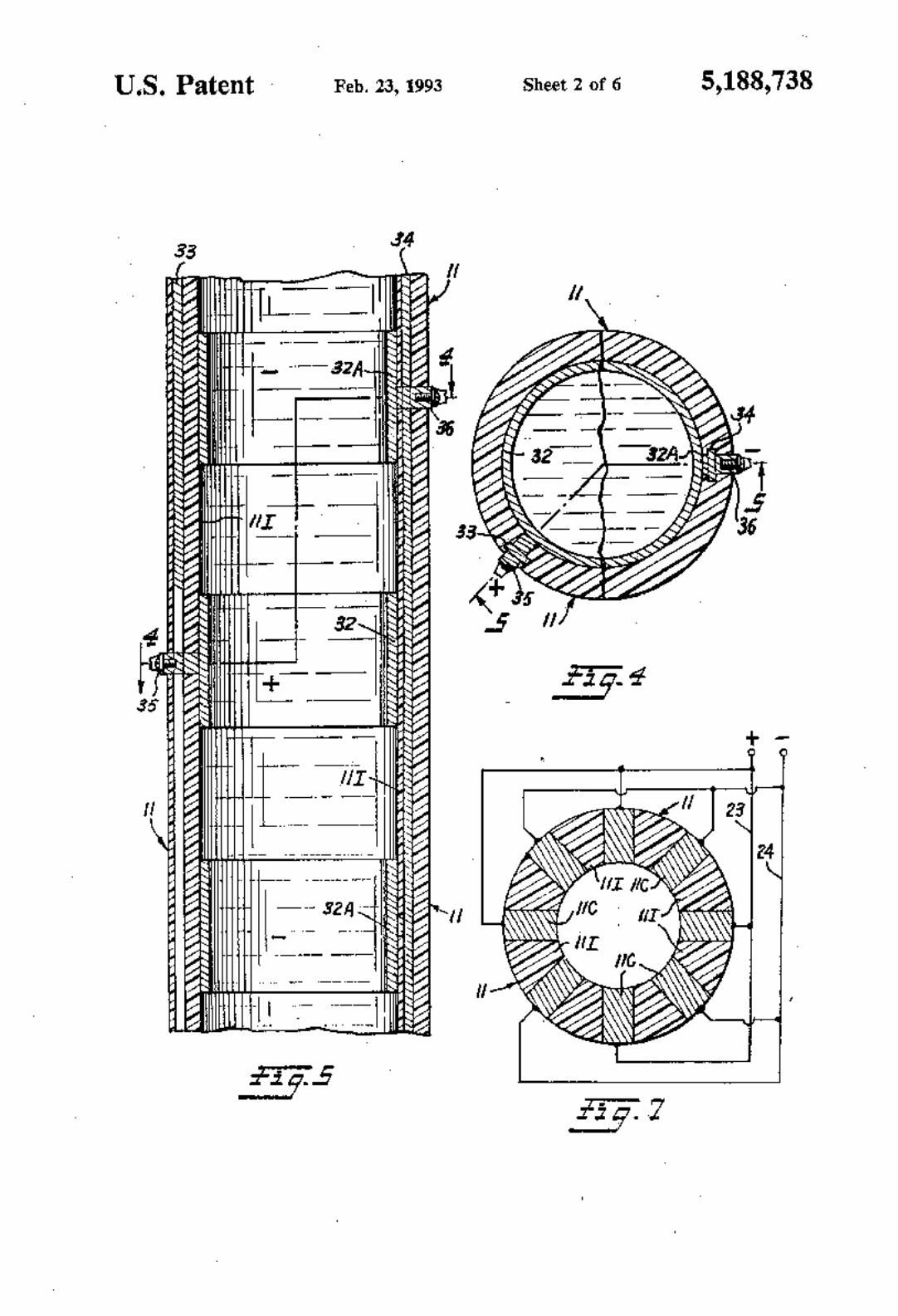
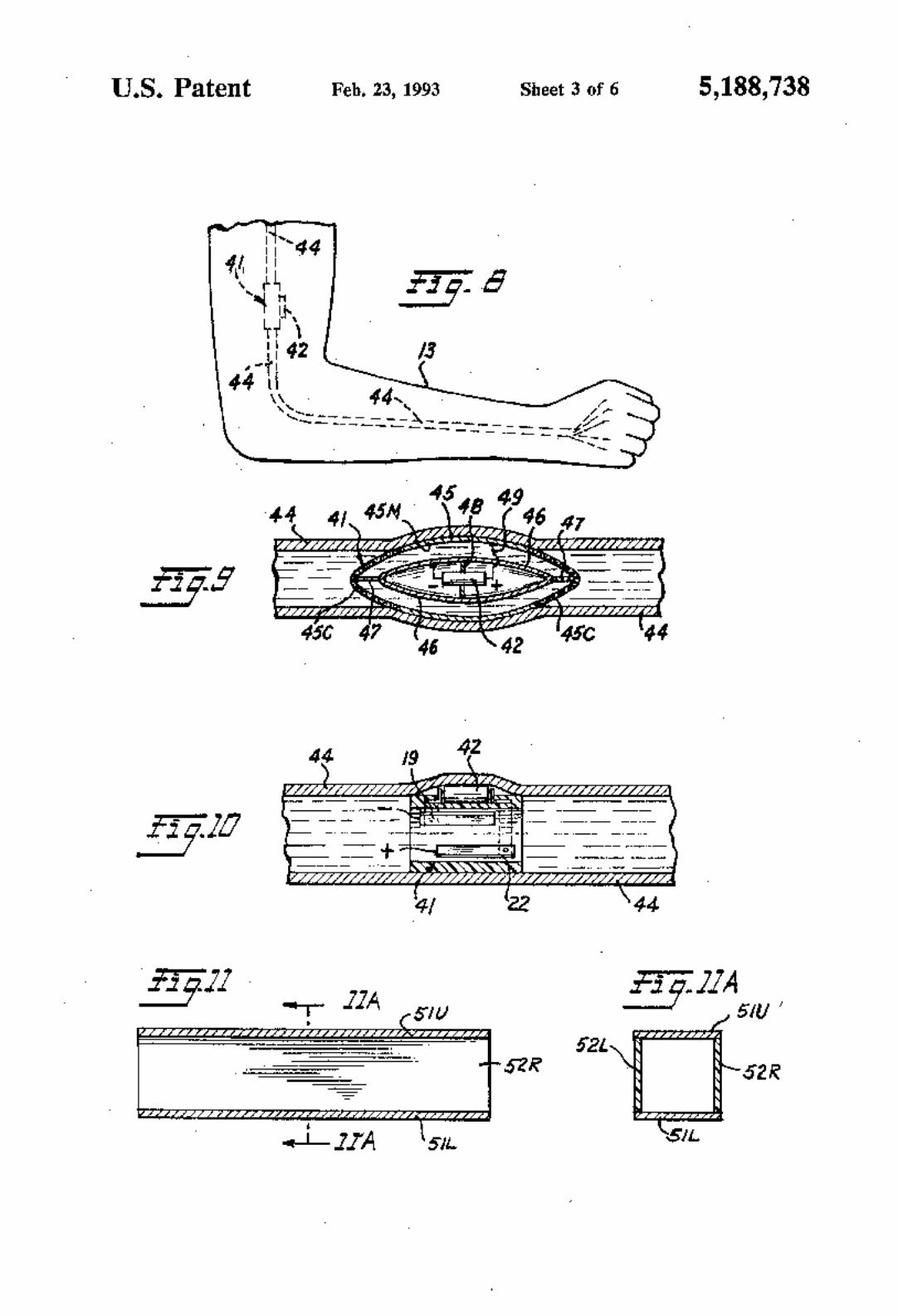
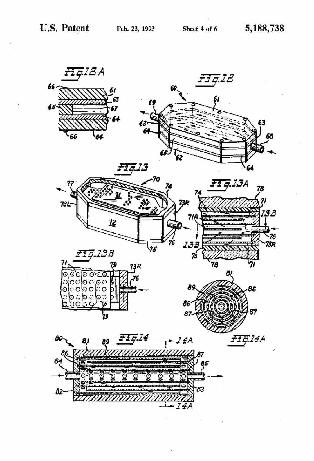


![United States Patent [19] [11] Patent Number: 5,834,708 ... Patent.pdf · NCR Model 7870 Scanner/Scale Product Model excerpts (pp. i, xiii through Xvi, 3—16 through 3—18) (1993)](https://img.pdfslide.net/doc/110x75/5e9aeb2747f3994e461ee683/united-states-patent-19-11-patent-number-5834708-patentpdf-ncr-model.jpg)