Embed Size (px)
Citation preview
111111 1111111111111111111111111111111111111111111111111111111111111111111111111111us 20130009896Al
(19) United States(12) Patent Application Publication
ZALIVA(10) Pub. No.: US 2013/0009896 Al(43) Pub. Date: Jan. 10,2013
(54) 3D FINGER POSTURE DETECTION ANDGESTURE RECOGNITION ON TOUCHSURFACES
(75) Inventor: Vadim ZALIVA, Saratoga, CA (US)
(73) Assignee: Lester F. LUDWIG, Belmont, CA (US)
(21) Appl. No.: 13/544,960
(22) Filed: Jul. 9, 2012
(60)
Related U.S. Application Data
Provisional application No. 611506,096, filed on Jul. 9,2011.
Publication Classification
(51) Int. CI.G06F 31041 (2006.01)
(52) U.S. CI. 345/173
(57) ABSTRACT
The invention provides 3D touch gesture recognition ontouch surfaces incorporating finger posture detection andincludes a touch user interface device in communication witha processing device. The interface device includes a sensorarray for sensing spatial information of one or more regions ofcontact and provides finger contact information in the form ofa stream of frame data. A frame is read from the sensor array,subjected to thresholding, normalization, and feature extrac-tion operations to produce a features vector. A multi-dimen-sional gesture space is constructed having desired set offea-tures, each represented by a space dimension. A gesturetrajectory is a sequence of transitions between pre-calculatedclusters, and when a specific gesture trajectory is detected, acontrol signal is generated.
"- "- ....'\
"-\"- '>.,,
'\
y
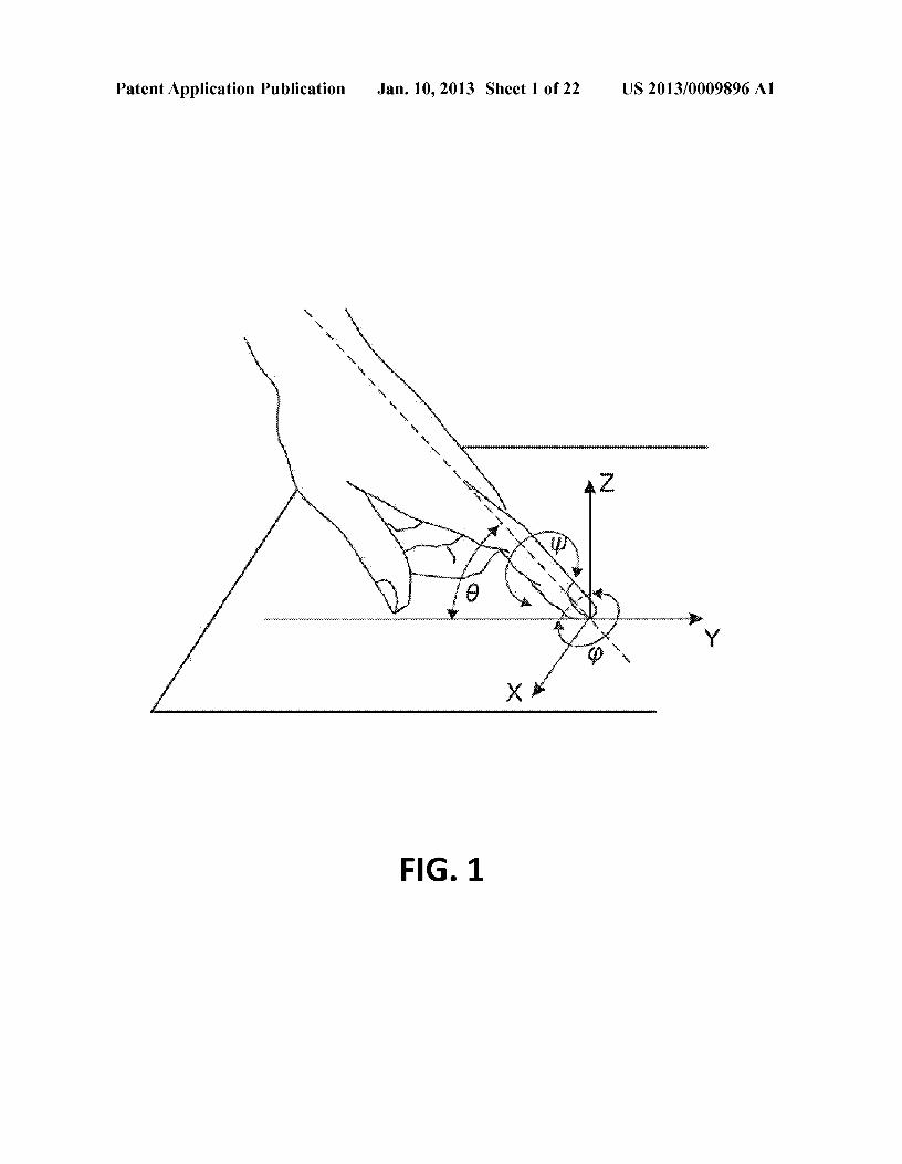
Patent Application Publication Jan. 10,2013 Sheet 1 of 22 US 2013/0009896 Al
y
FIG. 1
Patent Application Publication Jan. 10,2013 Sheet 2 of 22 US 2013/0009896 Al
Framepre-processing
Featureextraction
FIG.2
Patent Application Publication Jan. 10,2013 Sheet 3 of 22 US 2013/0009896 Al
FIG.3
Patent Application Publication Jan. 10,2013 Sheet 4 of 22 US 2013/0009896 Al
FIG.4
Patent Application Publication Jan. 10,2013 Sheet 5 of 22
:~.............,....,....,,,,..,,,,,,,....--.......--.......-.......-.......,....,....,,,,..,,,,,,....,,.,'~
I s::-l- \1. r
L~-=r
US 2013/0009896 Al
In•
-LL
Patent Application Publication Jan. 10,2013 Sheet 6 of 22 US 2013/0009896 Al
FIG.6
Patent Application Publication Jan. 10,2013 Sheet 7 of 22 US 2013/0009896 Al
z
y
FIG.7
Patent Application Publication Jan. 10,2013 Sheet 8 of 22 US 2013/0009896 Al
,Y
FIG.8
x
Patent Application Publication Jan. 10,2013 Sheet 9 of 22 US 2013/0009896 Al
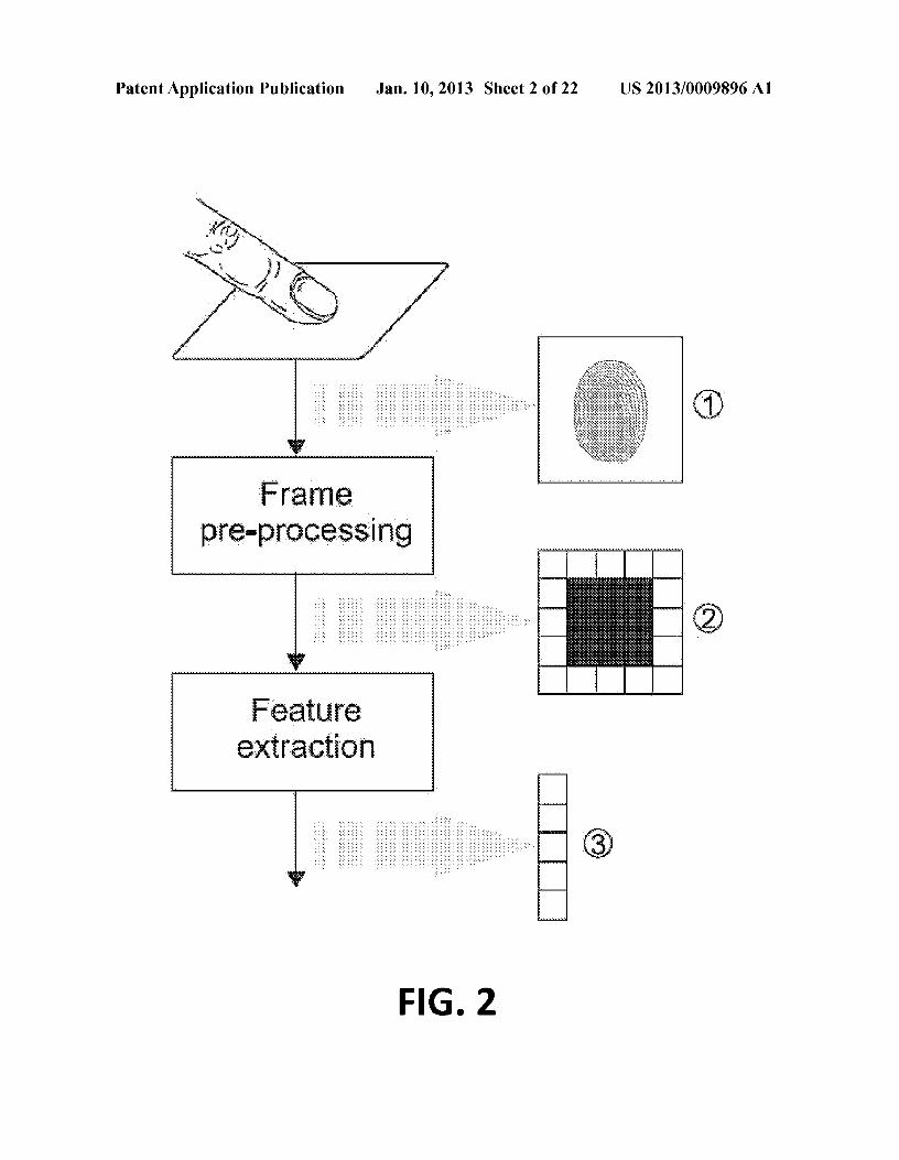
en•
-u.
Patent Application Publication Jan. 10,2013 Sheet 10 of 22 US 2013/0009896 Al
\\
\.
I I I i~
.0 0 g IS~ N
•~-u.
Patent Application Publication Jan. 10,2013 Sheet 11 of 22 US 2013/0009896 Al
-------"""T""-;------r--_,..,.
.r\I,)
\~
•~-LL
Patent Application Publication Jan. 10,2013 Sheet 12 of 22 US 2013/0009896 Al
FIG. 12
Patent Application Publication Jan. 10,2013 Sheet 13 of 22 US 2013/0009896 Al
o-M...----.-00oM/-
IT1Il..lll I·LI
UIIIIIIIIIIII flUb.
11111111111
IIIIII1 II II-«'
(,,)
-t- -III 1111 II
~gM-
II II III II II~.
\-oM-
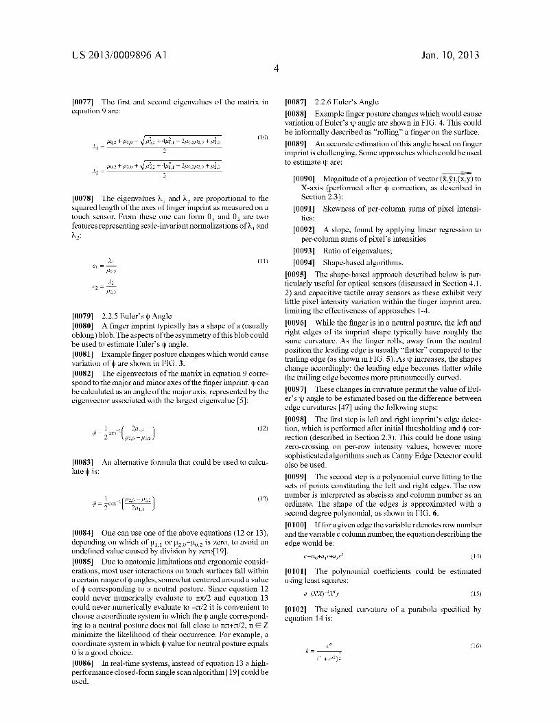
•~-LL
Patent Application Publication Jan. 10,2013 Sheet 14 of 22 US 2013/0009896 Al
'1 to 20 30 441 FF""''''-''''-'''''''''''''T''''-'''''''''''''''''''''-'''T'''''''''''''-''''''""'''''''''T-'''''''''''''''''''''-''''-''''''''''''''-T] 1
"L -Mt " l:... J 1 ....:t ,..,',.." l J30 44
FIG. 14
Patent Application Publication Jan. 10,2013 Sheet 15 of 22 US 2013/0009896 Al
~<~'0') ~~)
~. ~..cy< U)'(0:"'" ~'
--~:x,:,-;,;.,;.,;.,;.:.
Q"•
-u.
Patent Application Publication Jan. 10,2013 Sheet 16 of 22 US 2013/0009896 Al
FIG. 16
Patent Application Publication Jan. 10,2013 Sheet 17 of 22 US 2013/0009896 Al
FIG. 17
Patent Application Publication Jan. 10,2013 Sheet 18 of 22 US 2013/0009896 Al
•
-u.
Patent Application Publication Jan. 10,2013 Sheet 19 of 22 US 2013/0009896 Al
FIG. 19
Patent Application Publication Jan. 10,2013 Sheet 20 of 22
~::~iliC%W ~:·mti
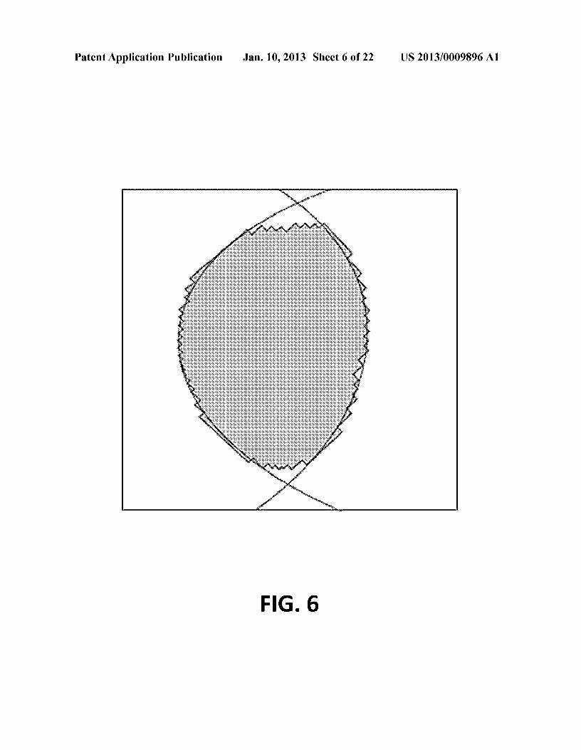
US 2013/0009896 Al
oN
•
-u.
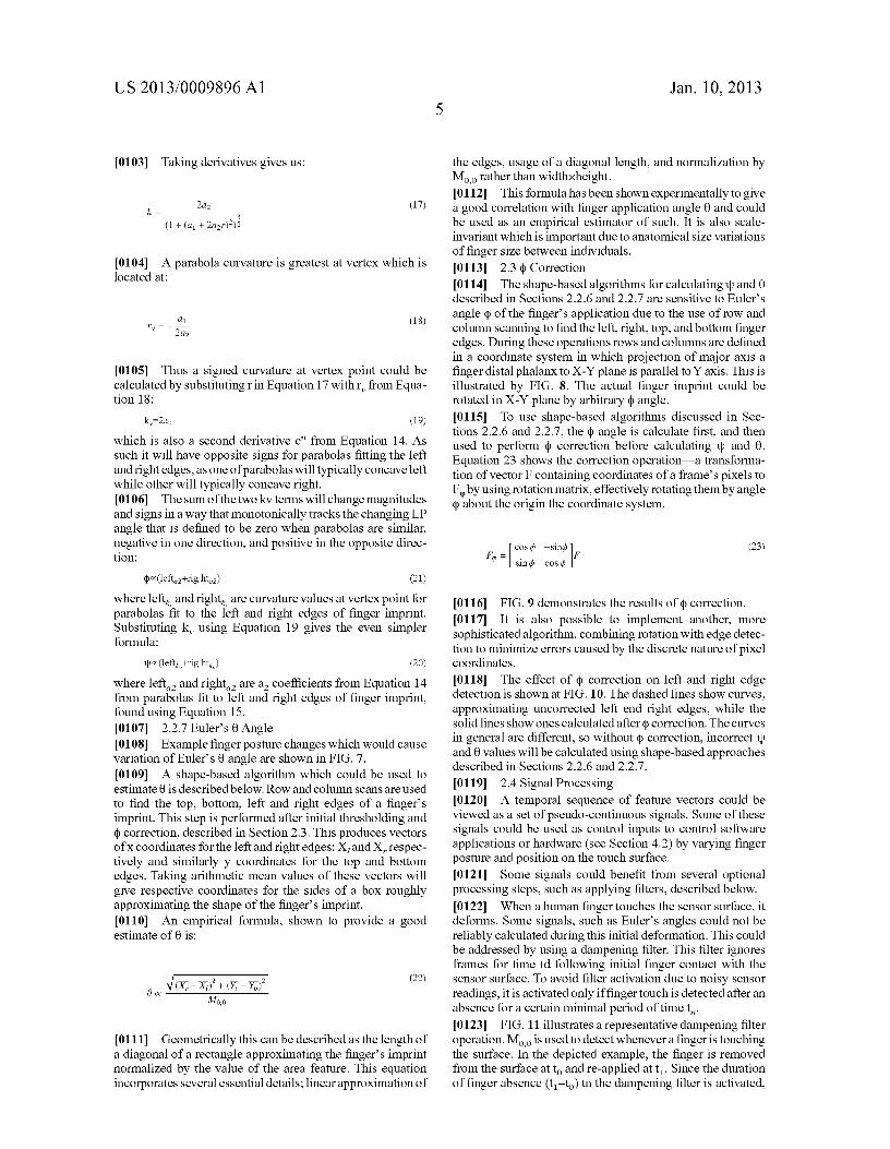
Patent Application Publication Jan. 10,2013 Sheet 21 of 22 US 2013/0009896 Al
FIG. 21
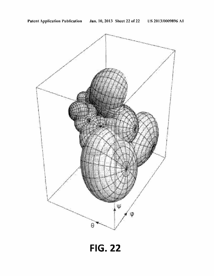
Patent Application Publication Jan. 10,2013 Sheet 22 of 22 US 2013/0009896 Al
FIG. 22
US 2013/0009896 Al
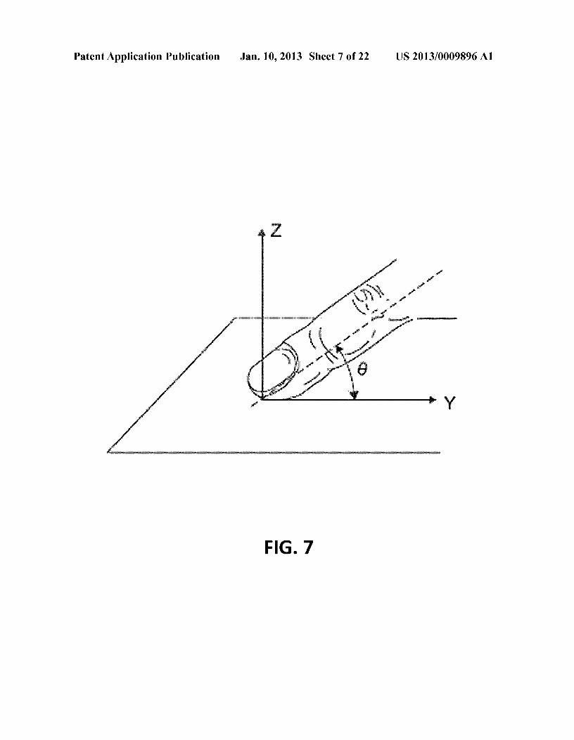
3D FINGER POSTURE DETECTION ANDGESTURE RECOGNITION ON TOUCH
SURFACES
CROSS-REFERENCE TO RELATEDAPPLICATIONS
[0001] Pursuant to 35 U.S.C. §119(e), this applicationclaims benefit of priority from Provisional U.S. Patent appli-cation Ser. No. 611506,096, filed Jul. 9, 2011, the contents ofwhich are incorporated by reference.
COPYRIGHT & TRADEMARK NOTICES
[0002] A portion of the disclosure of this patent documentmay contain material, which is subject to copyright protec-tion. Certain marks referenced herein may be common law orregistered trademarks of the applicant, the assignee or thirdparties affiliated or unaffiliated with the applicant or theassignee. Use of these marks is for providing an enablingdisclosure by way of example and shall not be construed toexclusively limit the scope of the disclosed subject matter tomaterial associated with such marks.
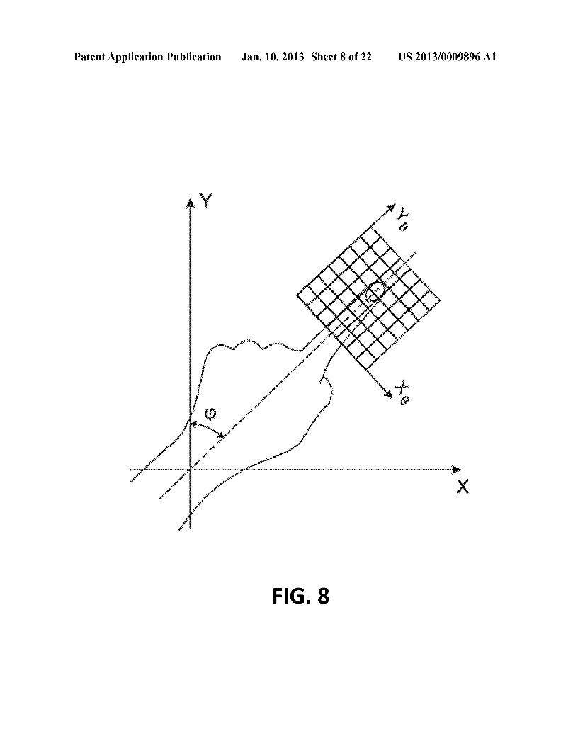
BACKGROUND OF THE INVENTION
[0003] The invention relates to gesture recognition ontouch surfaces, and more specifically to 3D finger posturedetection in the recognition of gestures with 3D characteris-tics.[0004] Touch surfaces are becoming more prevalent intoday' s technology, appearing as touch screens onmobile andstationary devices, laptop touchpads, electronic books, com-puter mice, etc. They find uses in many diverse areas such asmanufacturing and medical systems, assistive technologies,entertainment, human-robot interaction and others. Signifi-cant progress in touch-sensitive hardware has been made inrecent years, making available on the market touch sensorswhich are smaller, longer lasting, more accurate and moreaffordable than predecessors. With these technologicaladvancements, gesture-based interfaces are certain to becomemore prevalent as gestures are among the most primary andexpressive form of human communications [42].[0005] However modern models of gesture interaction ontouch surfaces remain relatively rudimentary. Companies likeApple and Microsoft are gradually introducing in their prod-ucts gesture metaphors, but they are still limited to abstractgestures like "two-finger swipe" or primitive metaphors suchas "pinch to zoom". However, significant additional progresscan be made in the area of gesture recognition, allowing forthe introduction of more complex gesture metaphors, andthus more complex interaction scenarios.[0006] One contributing factor currently hindering theintroduction of richer gestures is the simplistic 2D interactionmodel employed in mouse, trackball, and touch user interfacedevices. Essentially all modem touch interfaces consider onlythe planar finger contact position with the touchpad, limitingthemselves to measurement of a pair of coordinates for eachfinger application. A notable exception is the work by NewRenaissance Institute, related to the real-time extraction of3D posture information from tactile images [29, 15, 25].Using 3D finger posture rather than just 2D contact point ingesture definition opens the door to very rich, expressive, andintuitive gesture metaphors. These can be added to touchpads,touch screens, and can be implemented on the back of amouse [27, 18].
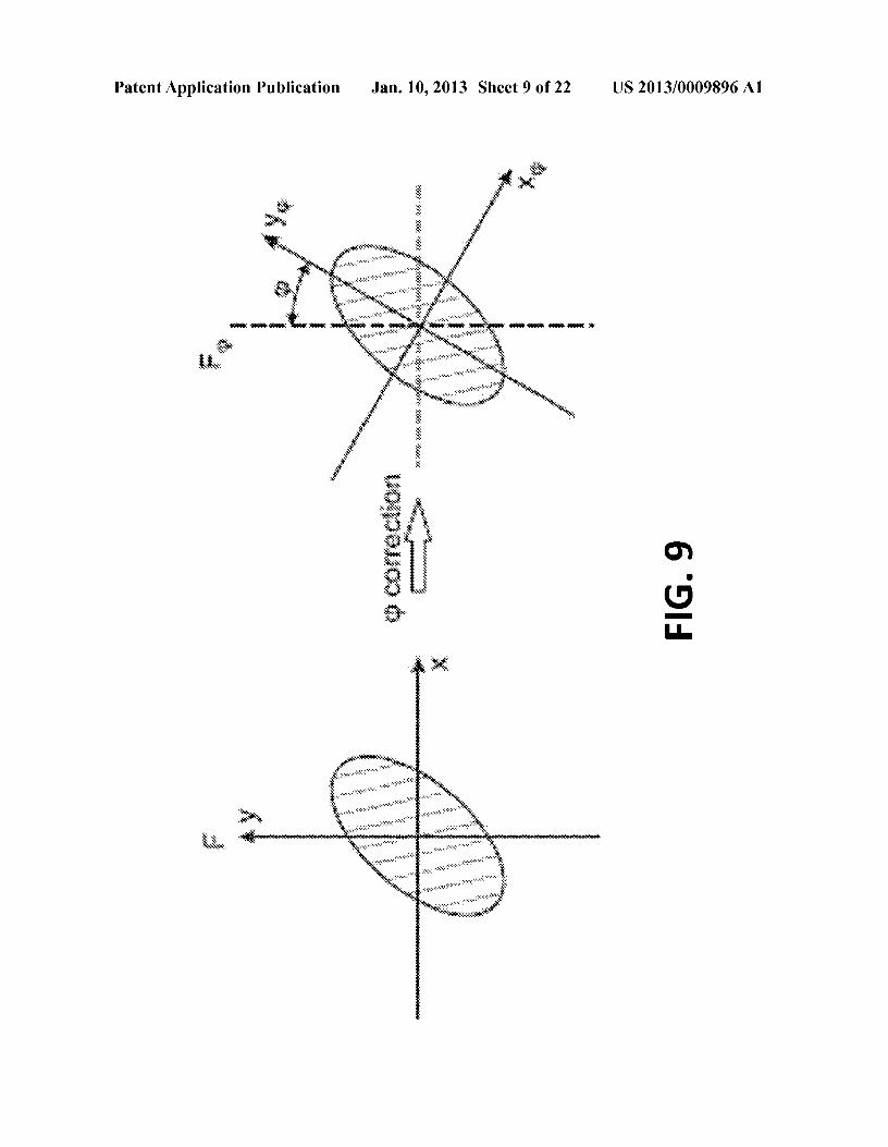
Jan. 10,20131
[0007] The present invention accordingly addresses ges-ture recognition on touch surfaces incorporating 3D fingerposture detection so as to implement recognition of gestureswith 3D characteristics.
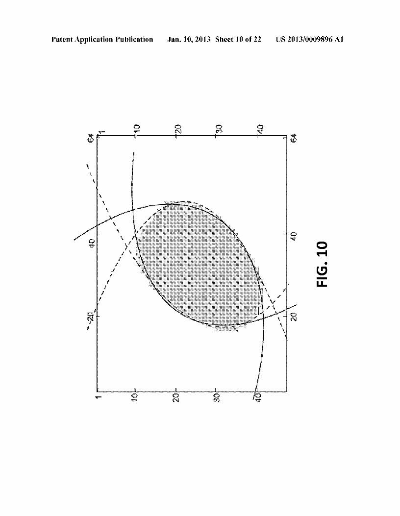
SUMMARY
[0008] For purposes of summarizing, certain aspects,advantages, and novel features are described herein. Not allsuch advantages may be achieved in accordance with anyoneparticular embodiment. Thus, the disclosed subject mattermay be embodied or carried out in a manner that achieves oroptimizes one advantage or group of advantages withoutachieving all advantages as may be taught or suggestedherein.[0009] The invention provides for gesture recognition ontouch surfaces incorporating 3D finger posture detection toimplement recognition of gestures with 3D characteristics.[0010] In one aspect of the invention, a system for 3Dgesture recognition on touch surfaces comprises a touch userinterface device in communication with a processing device.The interface device includes a sensor array for sensing spa-tial information of one or more regions of contact and pro-vides finger contact information in the form of a stream offrame data.[0011] The processing device reads frame data from thesensor array, produces modified frame data by performthresholding and normalization operations on the frame data,detects a first region of contact corresponding to a fingertouch, and produces a features vector by extracting at leastone feature of the modified frame data to. The processingdevise then creates a gesture trajectory in a multi -dimensionalgesture space wherein, detects a specific gesture, and gener-ates a control signal in response to the specific gesture. Themulti-dimensional gesture space comprises a plurality offea-ture vectors, and the gesture trajectory is a sequence oftran-sitions between regions of the multi-dimensional gesturespace[0012] Various features of the invention can be imple-mented singly or in combination. These features include:using a multivariate Kalman filter to overcome the presenceof random signal noise to avoid jittery cursor movement whenfinger position controls a user interface cursor; using Highperformance segmentation using Connected ComponentLabeling with subsequent label merging employing a Haus-dorff metric for the implementation of multi-touch capabili-ties; automating a threshold selection procedure by traininganArtificial Neural Network (ANN) and measuring how vari-0us thresholds affect the miss rate; constructing a multi-dimensional gesture space using a desired set of features (notjust centroid position and velocity), wherein each feature isrepresented by a space dimension; representing a gesturetrajectory as a sequence of transitions between pre-calculatedclusters in vector space ("Vector Quantization codebook")allows model it as a Markov Process; and implementing aprinciple component analysis operation.[0013] These and other features, aspects, and advantages ofthe present invention will become better understood withreference to the following description and claims.[0014] BRIEF DESCRIPTIONS OF THE DRAWINGS[0015] The above and other aspects, features and advan-tages of the present invention will become more apparentupon consideration of the following description of preferredembodiments taken in conjunction with the accompanyingdrawing figures, wherein:
US 2013/0009896 Al
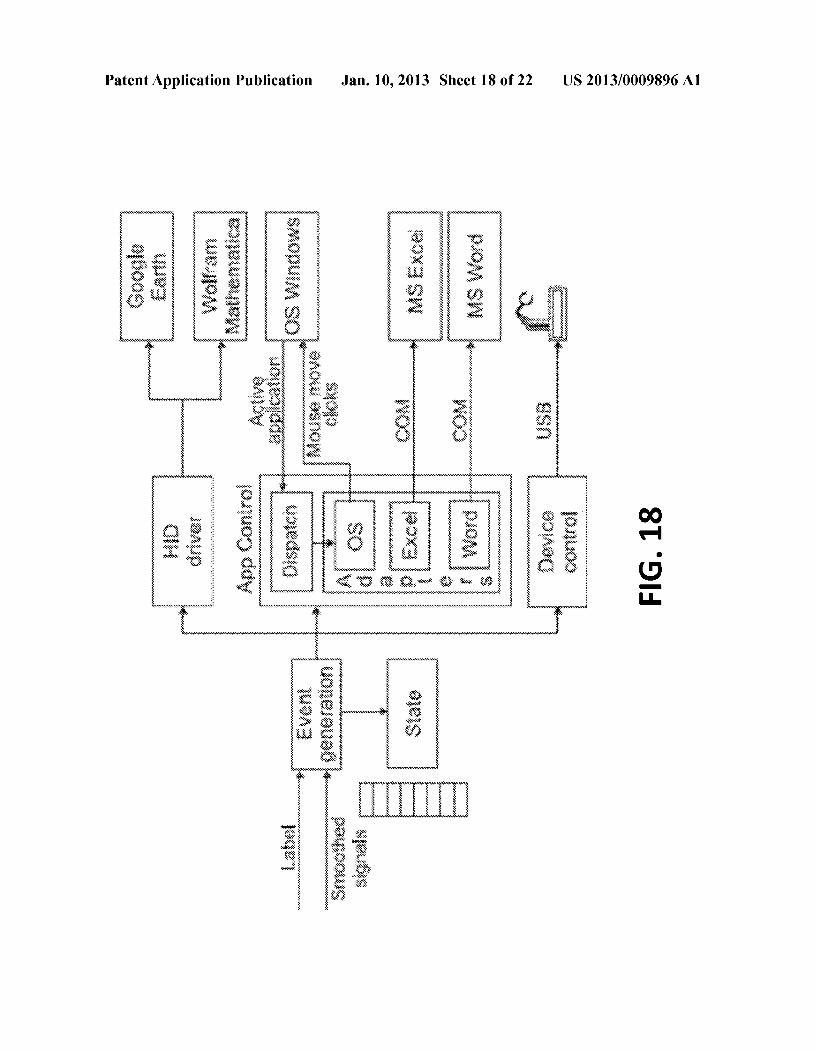
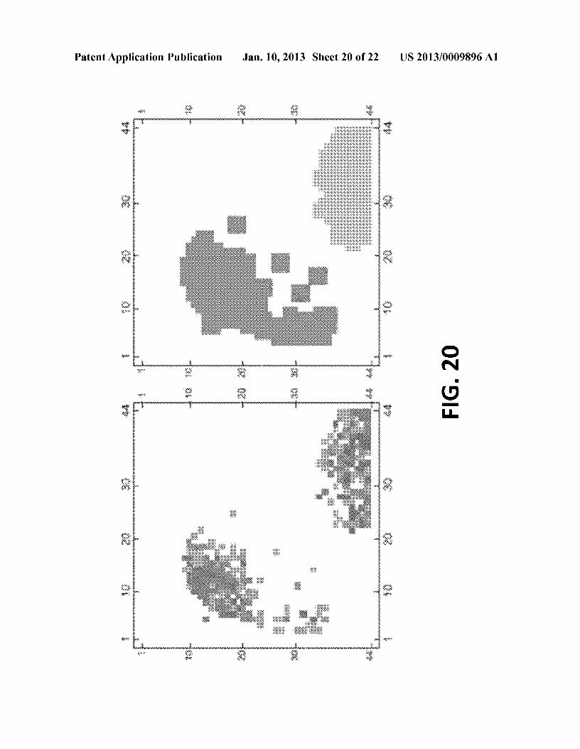
[0016] FIG. 1 depicts a 3D coordinate system with theZ-axis is defined vertically, perpendicular to X -Y plane usingnotation for angular features (Euler angles).[0017] FIG. 2 depicts a process provided for by the inven-tion wherein a frame is read from the sensor array, subjectedto thresholding and normalization operations resulting in amodified version of the frame which is in tum subjected tofeature extraction operations to produce a features vector.[0018] FIG. 3 depicts finger posture changes which wouldcause variation of estimate Euler's <jJ angle of the finger withrespect to the touch surface.[0019] FIG. 4 depicts finger posture changes which wouldcause variation of estimate Euler's 1jJ angle of the finger withrespect to the touch surface.[0020] FIG. 5 illustrates how as a finger rolls on a touchsurface away from a neutral position, the leading edge isusually "flatter" as compared to the trailing edge.[0021] FIG. 6 depicts a representation wherein the curvedshape of edges of an area of finger contact with a touch surfaceis approximated with second degree polynomials.[0022] FIG. 7 depicts finger posture changes which wouldcause variation of estimate Euler's 8 angle of the finger withrespect to the touch surface.[0023] FIG. 8 illustrates the use of row and colunm scan-ning to find the left, right, top, and bottom finger edges of afinger shape measurement, wherein rows and columns aredefined in a coordinate system in which projection of majoraxis a finger distal phalanx to X-Y plane is parallel to Y axis.[0024] FIG.9 shows results of a <jJ (yaw angle) correction asprovided for by the invention.[0025] FIG. 10 shows results of <jJ correction on left andright edge detection operations as provided for by the inven-tion.[0026] FIG. 11 depicts a representative dampening filteroperation as provided for by the invention.[0027] FIG. 12 shows a finger centroid trajectory ona touchsurface, with the dotted line showing the original value, andthe solid line a value smoothed by a Kalman filter as providedfor by the invention.[0028] FIG. 13 depicts an architecture of a gesture recog-nition module as provided for by the invention.[0029] FIG. 14 depicts a frame for a sample finger applica-tion comprising defective pixels.[0030] FIG. 15 depicts representative pressure distributionhistograms, based on statistics collected overtime for anoma-lous pixel with coordinates (14, 33) and its immediate neigh-bors.[0031] FIG. 16 depicts the Mean Squared Error between thepressure distribution histogram of every pixel and the pres-sure distribution histograms of its neighbors.[0032] FIG. 17 depicts a camera-based optical sensor thateasily and inexpensively allows acquisition of high resolutiontouch data and implements optical user interface sensing.[0033] FIG. 18 depicts an architecture of an example rep-resentative control system whose inputs are gesture label andsmoothed signals from a gesture recognition module such asthat depicted in FIG. 13.[0034] FIG. 19 depicts a representation of a OWl RoboticArm [l l jproduct, used in an application of the invention.[0035] FIG. 20 depicts an example of high performancesegmentation using Connected Component Labeling withsubsequent label merging employing a Hausdorff metricwherein original sensor data is shown along side the twodistinct finger images resulting from this operation.
Jan. 10,20132
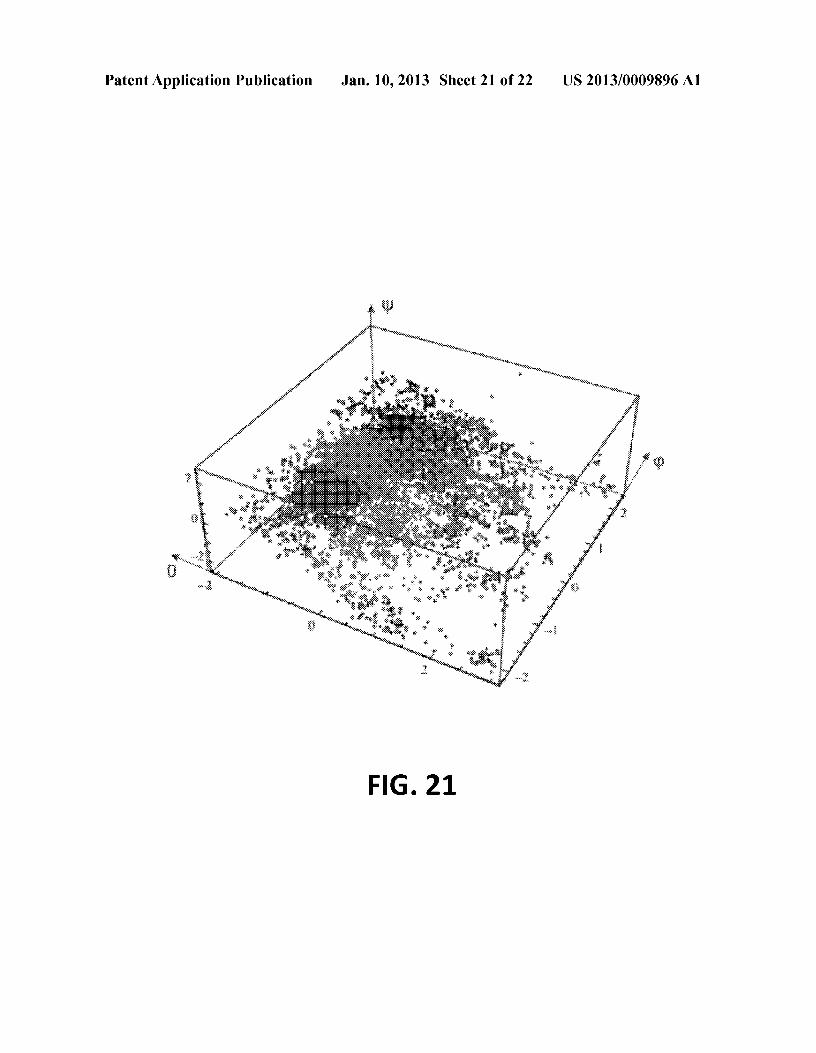
[0036] FIG. 21 depicts a three dimensional gesture spacewith gesture trajectory points clustered using Cosine Similar-ity as provided for by the invention.[0037] FIG. 22 depicts an alternate visualization of clustersfrom FIG. 21, here employing multivariate Gaussian repre-sented as an ellipsoid based on a covariance matrix of eigen-system and using 0.95 critical value of x" (Chi-square) distri-bution.
DETAILED DESCRIPTION
[0038] In the following description, reference is made tothe accompanying drawing figures which form a part hereof,and which show by way of illustration specific embodimentsof the invention. It is to be understood by those of ordinaryskill in this technological field that other embodiments maybe utilized, and structural, electrical, as well as proceduralchanges may be made without departing from the scope of thepresent invention.[0039] In the following description, numerous specificdetails are set forth to provide a thorough description ofvarious embodiments. Certain embodiments may be prac-ticed without these specific details or with some variations indetail. In some instances, certain features are described in lessdetail so as not to obscure other aspects. The level of detailassociated with each of the elements or features should not beconstrued to qualify the novelty or importance of one featureover the others.[0040] 1 Introduction[0041] The present invention accordingly addresses ges-ture recognition on touch surfaces incorporating 3D fingerposture detection so as to implement recognition of gestureswith 3D characteristics.[0042] 1.1 Finger Posture[0043] Consider the interaction scenario of the user per-forming finger gestures ona flat touch-sensitive surface. Eachfinger contacting the touch surface has a position and posture.To describe these, a coordinate system is introduced.[0044] In the coordinate system used in this article, an X -Yplane is aligned atop of the touch-sensitive surface, with the Yaxis aligned perpendicularly to the user. A Z-axis is definedvertically, perpendicular to X -Y plane. This is the coordinatesystem is illustrated in FIG. 1.[0045] Most existing touch interfaces operate only fromfinger position, which represents a point of contact betweenfinger and touch surface in X-Y plane with two-dimensionalcoordinates.[0046] However, this same point of contact could corre-spond to different finger postures in three dimensional space.A representation of the posture could be expressed via Eulerangles, commonly denoted by letters: (<jJ, 8, 1jJ). There areseveral conventions for expressing these angles, but in thisarticle Z-X -Z convention is used. The Euler angles describingfinger posture are shown in FIG. 1.[0047] When designing user interaction on a touch surfaceit is convenient to define a comfortable and convenient finger"neutral posture;" the posture which causes least discomfortto the user during long term use and is conveniently posed tobe a starting point for most common touchpad actions. Somerecommendations made in ergonomic studies [8] recommenda straight wrist posture while avoiding excess finger flexionand static loading of the arm and shoulder.[0048] 2 Feature Extraction[0049] In one implementation, the touch surface comprisesa touch-sensitive sensor array. Each sensor array reading is a
US 2013/0009896 Al
matrix of individual sensor's intensity values, representingpressure, brightness, proximity, etc. depending on the sensingtechnology used. This matrix of values at a given instant iscalled a frame and individual elements of this matrix arecalled pixels (in some literature, the term "sensels" is used).In an example arrangement, each frame first passes through a"frame pre-processing" step which includes pixel value nor-malization, accommodating defective sensors (see Section4.1.1), and thresholding (see Section 4.1.2).[0050] The next step is feature extraction: calculating a setof features (feature vector) for each frame. Each feature isdescribed in Section 2.2.[0051] The process above is illustrated in FIG. 2, wherein:
[0052] Step 1 represents a frame, as read from the sensorarray.
[0053] Step 2 represents a thresholded and normalizedversion of the frame, used for feature extraction.
[0054] Step 3 represents the output from the featureextraction step-a features vector.
[0055] 2.1 Image Moments[0056] Discrete Cartesian geometric moments are com-monly used in the analysis of two-dimensional images inmachine vision (for example, see [5], [39], [4])[0057] A representative example moments definitionarrangement employs various notion a pixel intensity func-tion. There are two useful kinds of pixel intensity function:
[0058] The first pixel intensity function, Iraw(X, y) sim-ply returns the frame pixel's value.
[0059] The second pixel intensity function will use a stepthreshold function and will return zero for sensor pixelvalues below a specified threshold and 1 for valuesabove it, effectively producing a binary image:
{1 Imw(x, y) >= threshold
hin(X, y) = 0 Imw(x, y) < threshold
[0060] The moment of order (p+q) for a gray scale image ofsize M by N with pixel intensities Iraw can be defined as:
M N
Mp.q = ~~xPyqlmw(x, y).x=l y=l
[0061] A variant of this same moment, using Ibin, is:
M N
Mp.q = ~~XPyqhin(X, y)x=l y=l
[0062] A central moment of order (p+q) for a gray scaleimage of size M by N with pixel intensities Iraw is defined as:
M N
Jip.q = ~ ~ (x - x)P(y - sr Imw(x, y)x=l y=l
Jan. 10,20133
[0063] A variant of the same central moment, using Ibin is:
M N
J.lpq = ~~(x-xJP(y-y)qhin(X, y)x=l y=l
(5)
[0064] 2.2 Features[0065] In this section some representative features that canbe extracted from a frame are provided.[0066] 2.2.1 Area[0067] Mo.o is the number of pixels in frame with valueexceeding the specified threshold. This is sometimes calledarea, and this term will be subsequently used to describe thisfeature.[0068] The term "finger imprint" will be used to refer to asubset of frame pixels with measurement values exceedingthe specified threshold-this corresponds to a region of con-tact by a user's finger. Note that in multi-touch operation ormulti-touch usage situations there will be multiple fingerimprints that can be measured from the touch sensor.[0069] 2.2.2 Average Intensity[0070] This feature represents an average intensity of non-zero pixels in the frame:
, Mo.ol=-
Mo.o
(6)
(1)
[0071] 2.2.3 Centroids[0072] Interpreting pixel intensity function as a surfacedensity function allows calculation of the geometric centroidof a finger imprint.[0073] While using Iraw as an intensity function gives:
- MlOX=-
Moo
(7)
- MOlY= ---
Moo
(2)
while using Ibin as an intensity function gives:
(3)
MlOX=-
Moo
MOlY= Moo
(8)
[0074] Centroids can be used to estimate finger position.See Section 2.4.1 for details.[0075] 2.2.4 Eigenvalues of the Covariance Matrix[0076] A covariance matrix OfIbin(X, y) is:
(4)
[J.l2.0 J.ll.l 1J.ll.l J.lO.2
(9)
US 2013/0009896 Al
[0077] The first and second eigenvalues of the matrix inequation 9 are:
A _ J.lO,2 + J.l2,O - ~ J.l6,2 + 4J.lT,1 - 2J.lO,2J.l2,O + J.l~,o1 - 2
A _ J.lO,2 + J.l2,O + ~ J.l6,2 + 4J.lT,1 - 2J.lO,2J.l2,O + J.l~,o2 - 2
[0078] The eigenvalues Al and A2 are proportional to thesquared length of the axes of finger imprint as measured on atouch sensor, From these one can form 81 and 82 are twofeatures representing scale-invariant normalizations of Al andA2:
[0079] 2,2,5 Euler's <p Angle[0080] A finger imprint typically has a shape of a (usuallyoblong) blob, The aspects of the asymmetry of this blob couldbe used to estimate Euler's <p angle,[0081] Example finger posture changes which would causevariation of <p are shown in FIG, 3,[0082] The eigenvectors of the matrix in equation 9 corre-spond to the major and minor axes of the finger imprint, <p canbe calculated as an angle of the major axis, represented by theeigenvector associated with the largest eigenvalue [5]:
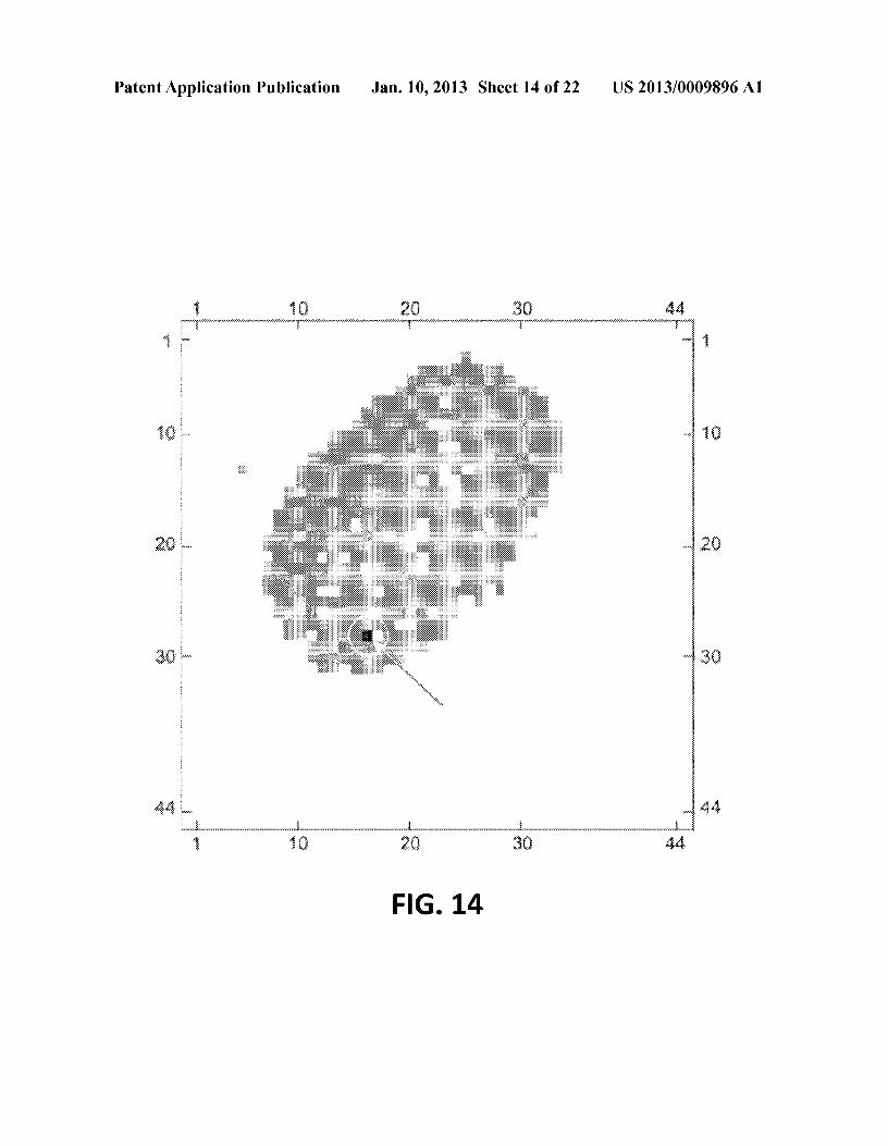
if; - ~tan-l(~)- 2 J.l2,O - J.lO,2
[0083] An alternative formula that could be used to calcu-late <p is:
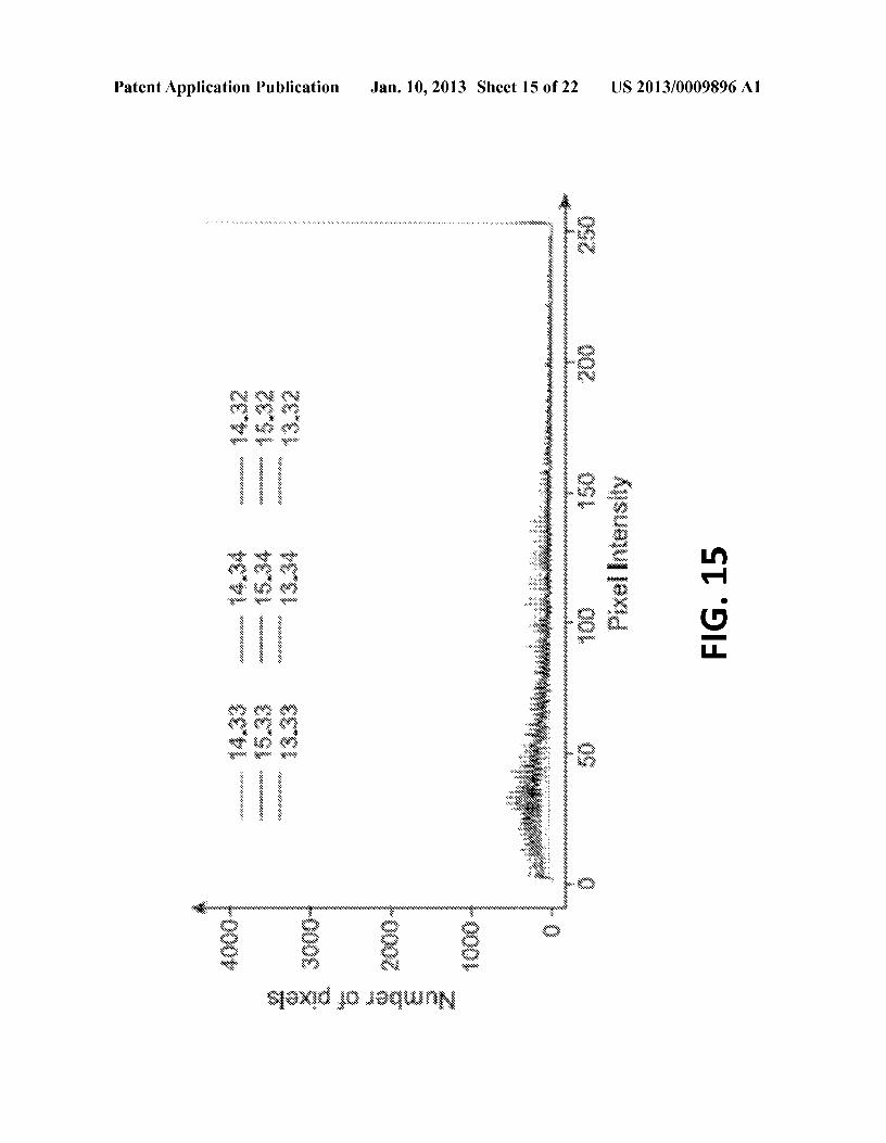
,J, 1 -1 (J.l2,O -J.lO,2)'f/= -cot ---2 2J.ll,1
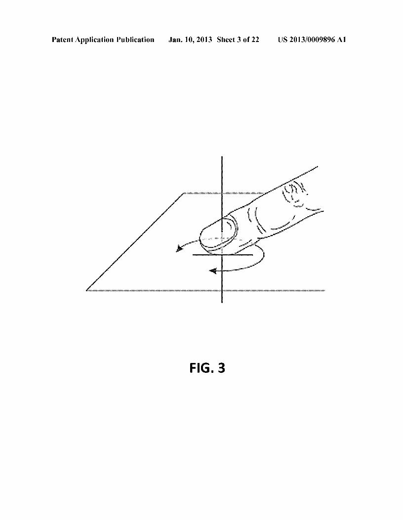
[0084] One can use one of the above equations (12 or 13),depending on which of fl1 1 or fl2 a-flo 2 is zero, to avoid anundefined value caused by' division by 'zero[19],[0085] Due to anatomic limitations and ergonomic consid-erations, most user interactions on touch surfaces fall withina certain range of <p angles, somewhat centered around a valueof <p corresponding to a neutral posture, Since equation 12could never numerically evaluate to ±rt/2 and equation 13could never numerically evaluate to -rt/2 it is convenient tochoose a coordinate system in which the <p angle correspond-ing to a neutral posture does not fall close to nrt+rt!2, n EOZminimize the likelihood of their occurrence, For example, acoordinate system in which <p value for neutral posture equalso is a good choice,[0086] In real-time systems, instead of equation 13 a high-performance closed- form single scan algorithm [19] could beused,
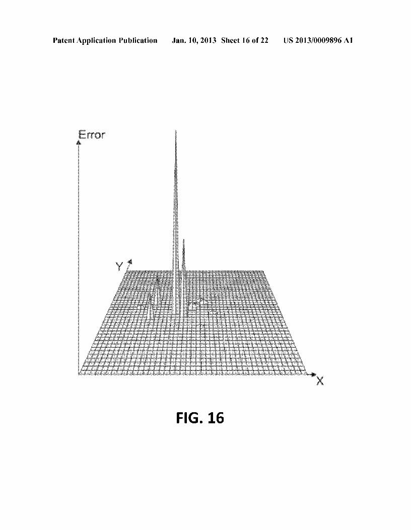
Jan. 10,20134
(10)
[0087] 2,2,6 Euler's Angle
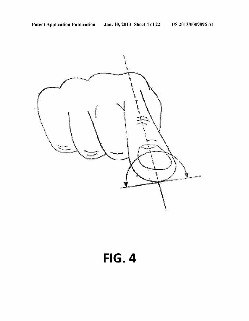
[0088] Example finger posture changes which would causevariation of Euler's 1.jJ angle are shown in FIG, 4, This couldbe informally described as "rolling" a finger on the surface,
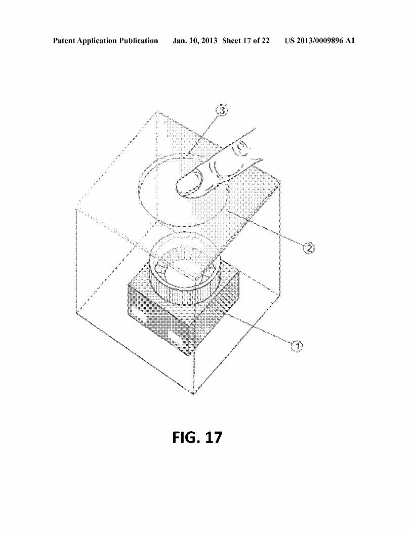
[0089] An accurate estimation of this angle based on fingerimprint is challenging, Some approaches which could be usedto estimate 1.jJ are:
(11)
[0090] Magnitude of a projection of vector (x,y),(x,y) toX-axis (performed after <p correction, as described inSection 2,3);
[0091] Skewness of per-column sums of pixel intensi-ties;
[0092] A slope, found by applying linear regression toper-column sums of pixel's intensities
[0093] Ratio of eigenvalues;[0094] Shape-based algorithms,
[0095] The shape-based approach described below is par-ticularly useful for optical sensors (discussed in Section 4,],2) and capacitive tactile array sensors as these exhibit verylittle pixel intensity variation within the finger imprint area,limiting the effectiveness of approaches 1-4,
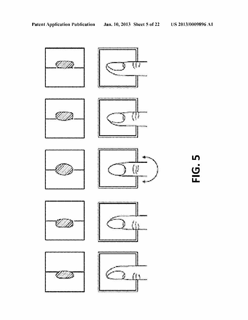
[0096] While the finger is in a neutral posture, the left andright edges of its imprint shape typically have roughly thesame curvature, As the finger rolls, away from the neutralposition the leading edge is usually "flatter" compared to thetrailing edge (as shown in FIG, 5), As 1.jJ increases, the shapeschange accordingly: the leading edge becomes flatter whilethe trailing edge becomes more pronouncedly curved,
[0097] These changes in curvature permit the value of Eul-er's 1.jJ angle to be estimated based on the difference betweenedge curvatures [47] using the following steps:[0098] The first step is left and right imprint's edge detec-tion, which is performed after initial thresholding and <p cor-rection (described in Section 2,3), This could be done usingzero-crossing on per-row intensity values, however moresophisticated algorithms such as Canny Edge Detector couldalso be used,
[0099] The second step is a polynomial curve fitting to thesets of points constituting the left and right edges, The rownumber is interpreted as abscissa and column number as anordinate, The shape of the edges is approximated with asecond degree polynomial, as shown in FIG, 6,
[0100] Iffor a given edge the variable r denotes row numberand the variable c column number, the equation describing theedge would be:
(12)
(13)
(14)
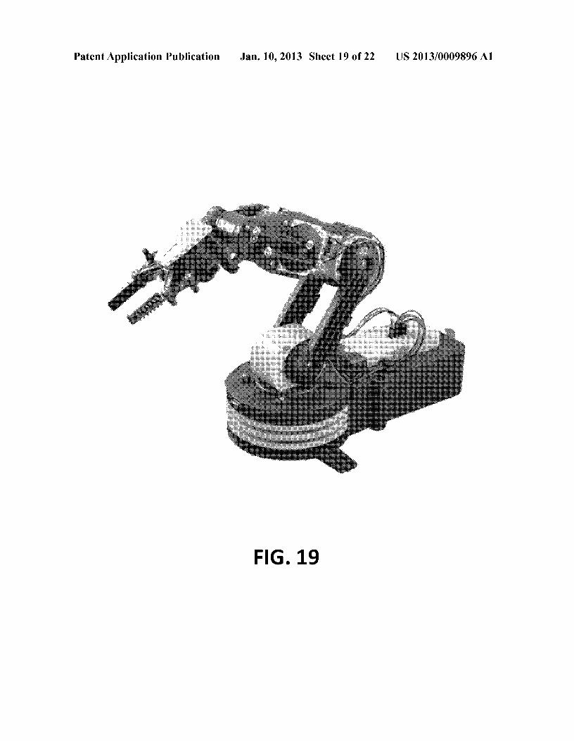
[0101] The polynomial coefficients could be estimatedusing least squares:
(15)
[0102] The signed curvature of a parabola specified byequation 14 is:
c"k=---3
(1 + c,2)2
(16)
US 2013/0009896 Al
[0103] Taking derivatives gives us:
k = 2_a=-2-----;-3
(1 + (al + 2a2r?)2
[0104] A parabola curvature is greatest at vertex which islocated at:
alrv=--
2a2
[0105] Thus a signed curvature at vertex point could becalculated by substituting r in Equation 17 with r, from Equa-tion 18:
which is also a second derivative c" from Equation 14. Assuch it will have opposite signs for parabolas fitting the leftand right edges, as one of parabolas will typically concave leftwhile other will typically concave right.[0106] The sum of the two kv terms will change magnitudesand signs in a way that monotonically tracks the changing LPangle that is defined to be zero when parabolas are similar,negative in one direction, and positive in the opposite direc-tion:
where left, and right; are curvature values at vertex point forparabolas fit to the l~ft and right edges of finger imprint.Substituting k, using Equation 19 gives the even simplerformula:
where lefta2 and rigln.., are a2 coefficients from Equation 14from parabolas fit to left and right edges of finger imprint,found using Equation 15.[0107] 2.2.7 Euler's 8 Angle[0108] Example finger posture changes which would causevariation of Euler's 8 angle are shown in FIG. 7.[0109] A shape-based algorithm which could be used toestimate 8 is described below. Rowand colunm scans are usedto find the top, bottom, left and right edges of a finger'simprint. This step is performed after initial thresholding and<p correction, described in Section 2.3. This produces vectorsof x coordinates for the left and right edges: X, and X, respec-tively and similarly y coordinates for the top and bottomedges. Taking arithmetic mean values of these vectors willgive respective coordinates for the sides of a box roughlyapproximating the shape of the finger's imprint.[0110] An empirical formula, shown to provide a goodestimate of 8 is:
[0111] Geometrically this can be described as the length ofa diagonal of a rectangle approximating the finger's imprintnormalized by the value of the area feature. This equationincorporates several essential details; linear approximation of
Jan. 10,20135
(17)
the edges, usage of a diagonal length, and normalization byMo,o rather than widthxheight.[0112] This formula has been shown experimentally to givea good correlation with finger application angle 8 and couldbe used as an empirical estimator of such. It is also scale-invariant which is important due to anatomical size variationsof finger size between individuals.[0113] 2.3 <p Correction[0114] The shape-based algorithms for calculating 1jJ and 8described in Sections 2.2.6 and 2.2.7 are sensitive to Euler'sangle <p of the finger's application due to the use of row andcolunm scanning to find the left, right, top, and bottom fingeredges. During these operations rows and colunms are definedin a coordinate system in which projection of major axis afinger distal phalanx to X-Y plane is parallel to Y axis. This isillustrated by FIG. 8. The actual finger imprint could berotated in X-Y plane by arbitrary <p angle.[0115] To use shape-based algorithms discussed in Sec-tions 2.2.6 and 2.2.7, the <p angle is calculate first, and thenused to perform <p correction before calculating 1jJ and 8.Equation 23 shows the correction operation-a transforma-tion of vector F containing coordinates of a frame's pixels toF<I> by using rotation matrix, effectively rotating them by angle<p about the origin the coordinate system.
(18)
(19)
[
COS ¢ -sin¢ 1F¢ = F
sin¢ cos¢
(23)
(21)
(20)
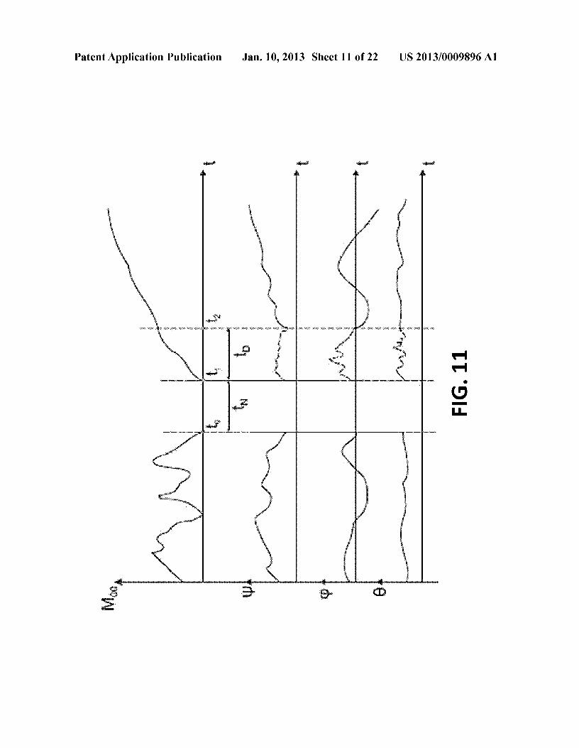
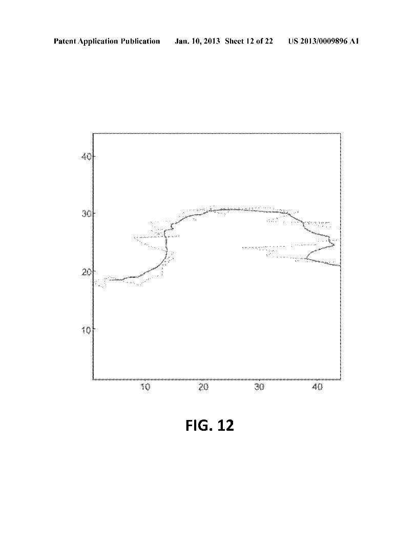
[0116] FIG. 9 demonstrates the results of <p correction.[0117] It is also possible to implement another, moresophisticated algorithm, combining rotation with edge detec-tion to minimize errors caused by the discrete nature of pixelcoordinates.[0118] The effect of <p correction on left and right edgedetection is shown at FIG. 10. The dashed lines show curves,approximating uncorrected left end right edges, while thesolid lines show ones calculated after <p correction. The curvesin general are different, so without <p correction, incorrect 1jJand 8 values will be calculated using shape-based approachesdescribed in Sections 2.2.6 and 2.2.7.[0119] 2.4 Signal Processing[0120] A temporal sequence of feature vectors could beviewed as a set of pseudo-continuous signals. Some of thesesignals could be used as control inputs to control softwareapplications or hardware (see Section 4.2) by varying fingerposture and position on the touch surface.[0121] Some signals could benefit from several optionalprocessing steps, such as applying filters, described below.[0122] When a human finger touches the sensor surface, itdeforms. Some signals, such as Euler's angles could not bereliably calculated during this initial deformation. This couldbe addressed by using a dampening filter. This filter ignoresframes for time td following initial finger contact with thesensor surface. To avoid filter activation due to noisy sensorreadings, it is activated only if finger touch is detected after anabsence for a certain minimal period of time tn'[0123] FIG. 11 illustrates a representative dampening filteroperation. M, 0 is used to detect whenever a finger is touchingthe surface. I~ the depicted example, the finger is removedfrom the surface at to and re-applied at t1. Since the durationof finger absence (t1-tO) tn the dampening filter is activated,
(22)
US 2013/0009896 Al
suppressing output of unreliable calculations of <p, 1jJ, and 8signals td, until t2. The dashed line shows suppressed signalsvalues.[0124] A signal's random noise could be attenuated byusing a low-pass filter. A causal filter approach is used toestimate the value of a signal at a given point in time usinglocally weighted scatterplot smoothing (LOWESS)[3] modelapplied to ws prior values. These values are called smoothingwindow. Such filter is used for smoothing finger posture-related signals such as Euler's angles. Smoothing of fingerposition signals is discussed in Section 2.4.1.[0125] 2.4.1 Estimating Finger Position[0126] A touchpad or touchscreen are examples of a com-mon use of touch surface where the user controls applicationsby changing the position of their finger on the surface. Insoftware applications, the position of the finger is expressedas 2D coordinates in X -Y plane. A finger position estimationproblem is calculating such 2D coordinates representing fin-ger position in a frame.[0127] As mentioned in Section 2.2.3, centroids can beused to estimate finge~p~sition. An argument for choosingbetween (cy, cy) and (x, y) for different types of sensors isprovided in Section 4.1.[0128] Regardless of which centroid is used, the presenceof random signal noise could cause jittery cursor movementwhen finger position is used to control the cursor. For centroidsignals, a multivariate Kalman filter [10] is used as its empiri-cal performance is better than that of a local linear regressionfor this application. FIG. 12 shows a representative fingercentroid trajectory on a touch surface, with the dotted lineshowing the original value, and the solid line a valuesmoothed by the Kalman filter.[0129] One of the effects of smoothing with a causal filter isthat after the finger has been removed from the sensor whilethere are at least 2 previous signal values in the smoothingwindow, it would continue to estimate "phantom" values ofthose signals. For example, at a rate of 100 frames per secondwith a 30 frame smoothing window size, the causal LOWESSsmoothing filter will produce signal values for 280 ms afterthe finger has been removed. This effect could noticeable tothe user. To avoid this, an instant cut-off feature is introduced.It prevents the use of the LOWESS smoother if finger pres-ence is not detected in the current frame (the area signal is 0).[0130] 3 Gesture Recognition[0131] Extracted temporal sequence of feature vectorscould be used to recognize a set of predefined gestures, per-formed by changing finger posture and position on a touchsurface. The gesture recognition module processes a streamof feature vectors (in real time) and attempts to recognize agesture presence and boundaries.[0132] A user can perform a variety of gestures. The mostbasic gestures involve the variation of only a single parameterof finger posture or position. The initial set of such basicgestures could be:
[0133] Sway User changes x coordinate of finger posi-tion (swiping the finger left to right or right to left).
[0134] Surge User changes y coordinate of finger posi-tion (swiping the finger towards or away from the body).
[0135] Heave User changes i (varying the pressure,applied by the finger to the touchpad).
[0136] Yaw User changes <p, varying correspondingangle, as shown on FIG. 3.
[0137] Roll User changes 1jJ, varying correspondingangle, as shown on FIG. 4.
Jan. 10,20136
[0138] Pitch User changes 8 signal, varying correspond-ing angle, as shown on FIG. 7.
[0139] The feasibility of recognition of posture-indepen-dent gestures such as surge, sway and to a small extend heave(i.e. finger taps) has been proven and recognition of suchgestures have been incorporated into existing products suchas Apple MacOS. However recognition of gestures involvingvariations of 3D finger posture such as yaw, roll and pitchremains relatively unstudied at the time of writing this articlewith exception of work by NRI [29, 19,25,47,46,38,37].[0140] A gesture recognition problem could be viewed as apattern recognition problem sometimes referred to assequence labeling [32], and commonly studied in the field ofspeech recognition. It has been formulated as:[0141] "In sequence labeling problems, the output is asequence of labels y=(y', y1 which corresponds to anobservation sequence x=(x', , x"). If each individual labelcan take value from set E, then the structured output problemcan be considered as a multiclass classification problem withI~ITdifferent classes."[0142] Representing each gesture as two directional labelsproduces the following initial set of gesture labels ~o:
.Lo = {yaw1eft, yawrighf' rollleft, rol!right. pitch1ejf' pitchright} (24)
[0143] To represent a situation where no gesture is present,an additional null label, denoted by symbol D is introduced,producing the final set oflabels ~:
~>{Lo,D} (25)
[0144] Each frame (at time t) could be represented by afeature vector, for example:
S, = {Mo.o, l, x, y, x, y, e1, e2, ¢, e, i/I) (26)
[0145] A sliding window approach to real-time sequencelabeling is used, where the classification of a sample at time tis made based on wd current and previous samples (s., St-1, ... , s,-(wa 1)). The value wd is called gesture recognitionwindow size. This window size is selected experimentally,based on several factors such as sampling rate and averagegesture duration.[0146] The input of the classifier at time t is the concatena-tion of wd most recent feature vectors:
(27)
[0147] The output of the classifier a label from the set E.[0148] 3.1 Artificial Neural Network Classifier[0149] Although other approaches could be employed,some of which are discussed in Section 5, in this section theexample of an Artificial Neural Network (ANN) classifierwill be used to assign the labels. Alternate classifier imple-mentations are possible (for example [34]) and these areprovided for by the invention.[0150] In general the classifier will have Ixtl inputs and I~oIoutputs. The input of the classifier is vector x, (see equation24).[0151] Based on this vector oflabel probabilities, a singlelabel is selected by applying accept and reject thresholds: thelabel with maximal threshold is chosen if its probability isabove the acceptance threshold and all other label probabili-
US 2013/0009896 Al
ties are below the rejection threshold. This classificationapproach is sometimes called "one-of-n with confidencethresholds"[ 40]. If no label passes the threshold test the nulllabel (D) is assigned.[0152] In an example implementation a simple feed-for-ward ANN with two hidden layers using the tanh activationfunction is used. The ANN output layer uses the logisticactivation function, so as to produce outputs in [0, 1] interval,convenient for probabilistic interpretation. For training, avariation [9] of the Rprop learning algorithm is used.[0153] Under certain conditions some features could not becalculated. In this case the invention provides for some imple-mentations to employ a special NULL symbol, indicating amissing value in place of the feature value in the featurevector. An ANN could not handle such input values, and theyhave to be handled outside of ANN classification logic. Two"missing value" cases could be distinguished and separatelyhandled:[0154] 1. If within a given window a feature is NULL for allframes; do not send these windows to the ANN classifier andassume that no gesture is present, assigning null label.[0155] 2. If within a given window for a feature some valuesare NULL; try to interpolate those missing values by replac-ing them with the mean value for the respective feature acrossthe window.[0156] 3.2 Principal Component Analysis[0157] All the features discussed in Section 2.2 correspondto geometric features of the finger's 3D posture and 2D posi-tion such as Euler's angles, finger position, etc. However,higher order moments can also be used as abstract quantitiesin gesture recognition. Since it is difficult to predict a. priorythe usefulness of different features in classification decisions,one approach is to feed as much information as possible to anANN classifier and let it decode (brute force approach).Unfortunately, it has been shown that increasing ANN inputsabove a certain number can actually cause a degradation ofthe performance of the ANN classifier [1]. Also, such anincrease has a noticeable impact on training time and requiredCPU resources. The number of ANN cells and requiredamount of training data grows exponentially with dimension-ality of the input space [1]. This is a manifestation of an effectthat is sometimes referred to as "the curse of dimensionality."[0158] To address this problem, one can employ a dimen-sionality reduction technique such as a Principal ComponentAnalysis (PCA). PCA can be defined as "an orthogonal pro-jection of the data into a lower-dimensional linear space,known as principal subspace, such that the variance of theprojected data is minimized." [2][0159] A PCA operation is applied to an extended featurevector which, in addition to those features defined in s, (seeequation 26), include additional abstract moments. Anexample feature vector that can be used as PCA input is:
Spca = ft, X,)I, x, y, Mo,o, MO,l, M1,Q, Mo,o, MO,l'
M1•0, Pl.l' P2•0, PO•2' P2.l' P1•2, P2•2, el, e2, ¢, e, I/I}
[0160] Each feature in the feature vector is scaled to haveunit variance and shifter so as to be mean centered. The PCAoperation comprises a linear transformation which, whenapplied to Spea, produces a list of i, each corresponding todimension in a new space. Components are ordered bydecreasing variance. Some of the components which have
Jan. 10,20137
standard deviations significantly lower than the first compo-nent could be omitted from the input provided to the ANN. Itis noted that a manually set variance threshold can be used.Alternatively, a threshold selection procedure could be auto-mated by training the ANN and measuring how variousthresholds affect the miss rate.[0161] Assuming that the original data has N intrinsicdegrees of freedom, represented by M features with M>N,and some of the original features are linear combinations ofothers, the PCA will allow a decrease in the number of dimen-sions by orthogonally projecting original data points to a new,lower-dimension space while minimizing an error caused bydimensionality decrease.[0162] The PCA parameters and transformation are calcu-lated offline prior to use, based on a sample dataset of featurevectors calculated from representative sequence of pre-re-corded frames. The parameters consist of: a vector of scalingfactors P, (to scale values to have unit variance), a vector ofoffsets Po (to shift values to be mean centered) and transfor-mation matrix Pt.[0163] During ANN training and ANN-based gesture rec-ognition, these three parameters are used to convert the fea-ture vector Spea into a vector of principal components ct:
(29)
[0164] An ANN classifier is used as described in Section3.1, but instead of x" a vector rt (see Equation 30) is used asinput:
(30)
(28)
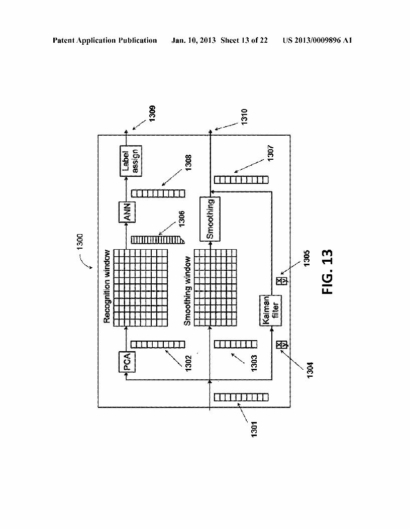
[0165] 3.3 Gesture Recognition Module Architecture[0166] An example architecture for a gesture recognitionmodule 1300 [48] is shown in FIG. 13. The input of themodule 1301 is a vector offeatures Spca, which is the outputof the feature extraction module, shown on FIG. 2. A PCAtransformation is applied to this vector, resulting in c, 1302. Alast wd values 1303 of c, are accumulated in a recognitionwindow. The content of this window is then concatenated intoa long vector rt 1306 which is submitted as input of ANN. Theoutput of ANN 1308 is a vector of label probabilities. It isinterpreted by the label assigning module, which decideswhat label to assign to the current frame. The assigned label1309 is one of the outputs of the gesture recognition module.[0167] Parallel to the "label" data flow depicted in the upperportion of FIG. 13, the same features represented by the inputvector spea 1301 can also be used to obtain smoothed signalsresponsive representing parameters of finger position andposture. A subset s, of values from input vector spea 1301 issplit into two vectors: vector of spatial coordinates of thecentroid 1304 and the vector of remaining features from St.
The centroid is smoothed using the Kalman filter, resulting ina vector of smoothed centroid coordinates 1305. Other fea-tures are smoothed using LOWESS based on ws last featurevectors, accumulated in the smoothing window. Thesesmoothed signals are concatenated back with the vector ofsmoothed centroid coordinates 1305 to produce a vector 1307which contains a smoothed version of St. This vector is also anoutput of this module 1310.[0168] 4 Example Implementations[0169] As an example of ANN Classifier training, one canrecord a dataset of frames from a touch-sensitive array col-lected while users perform various gestures. Labelingdescriptions can be manually or automatically transcribed foreach frame recording an expected gesture label. Using estab-lished cross-validation techniques, the dataset can addition-
US 2013/0009896 Al
ally be partitioned into training and validation sets. The firstcan be used for training ANN classifier and the second can beused to measure the performance of trained ANN classifier.[0170] Such a classifier can be implemented, for example,in c++ using FANN [33] library. The performance of atrained ANN classifier can be sufficient to perform gesturerecognition in real-time on a regular consumer-level PC at atactile sensor frame capture rate of 100 FPS.[0171] A gesture recognition with a miss rate below 1 per-cent as measured on validation data set can be readily beobtained.[0172] 4.1 Tactile Sensing Hardware[0173] There are a variety of types of tactile sensors, forexample pressure-based, capacitive and optical. In variousembodiments, each has individual advantages and chal-lenges.[0174] 4.1.1 Pressure Sensor[0175] An example pressure sensor array, for example asmanufactured by 'Iekscan, comprises an array of 44-by-44presurre-sensing "pixels," each able to report 256 pressuregradations. Although the maximum supported frame sam-pling rate can be 100 FPS, it can be shown that the algorithmspresented as part of the invention work at rates as low as 50FPS without significant loss of performance. This is impor-tant as lower frame rates require less CPU resources.[01~]_ A finger position on this sensor could be estimatedby (x, y). H~w~ver due to the slightly asymmetrical shape ofthe finger, (x, y) are shown to better represent the perceivedcontact point of the finger.[0177] This particular senor posed several challenges: mea-surements can be noisy, and the sensor can have defectivepixels. Moderate levels of noise does not prove to be a sig-nificant problem as the algorithms described are tolerant to asmall amount of random errors in input data.[0178] The problem with defective pixels can be muchmore significant. FIG. 14 shows an example of the frame fora sample finger application. In this example, one of the pixels(marked with an arrow) consistently provides a pressurevalue significantly higher than neighboring pixels.[0179] During normal touch-sensitive surface use, differentpixels are loaded at different times with different pressures.Over time statistics can be collected for each pixel, on distri-bution of discrete pressure values reported by this particularpixel during an observation period. Such a statistic can berepresented as a histogram of pixel value distribution for agiven pixel over time.[0180] For a perfectly calibrated sensor array withoutdefective pixels such a histogram should be very similar forall pixels, given the same pressure application patterns. How-ever, under typical use applications patterns differ dependingon pixel location within an array. Because of that, histogramsfor pixels located in different parts of the touchpad will differ.However, sufficiently nearby pixels should have similar his-tograms. This assumption allows the detection of anomalouspixels as those which have histograms which are significantlydifferent from their neighbors. FIG. 15 shows pressure distri-bution histograms based on statistics collected over time foran anomalous pixel with coordinates (14, 33) and its imme-diate neighbors, and also shows the pressure value distribu-tions for the anomalous pixel and for its immediate neighbors.[0181] Accumulating statistics of value distribution foreach pixel over time and comparing each pixel to its neigh-bors allows identification of pixel outliers (for example usingChauvenet's criterion).
Jan. 10,20138
[0182] FIG. 16 shows for every pixel a Mean Squared Errorbetween its own pressure distribution histogram and the pres-sure distribution histograms of its neighbors. The measure-ments provided for several pixels behave significantly differ-ent and these pixels are considered anomalous.[0183] Once identified, such defective pixels could be dealtwith in different ways. In an embodiment, these can be treatedin calculations as missing values, effectively ignoring them.Another approach is to estimate or interpolate correct theirvalues based on accumulated statistics or other information.[0184] Statistical data used in this algorithm could be col-lected during normal sensor usage. This permits the detectionof anomalous pixels and accommodates for their presence ina manner completely transparent to the user.[0185] 4.1.2 High Resolution Optical Touch Sensor[0186] FIG. 17 depicts a camera-based optical sensor.Although in some implementations such an arrangement canbe somewhat physically large, this arrangement easily andinexpensively allows acquisition of high resolution touchdata and implements optical user interface sensing. In is notedthat NRI has developed technology making use of the lightsensing properties of OLED (Organic Light Emitting Diode)displays and OLED transparent overlays as a high resolutionoptical sensing touch screen [23].[0187] The camera-based optical sensor can, for example,comprise an upwards-facing video camera directed to viewthe nnderside of a transparent touch surface that may be fittedwith an aperture bezel, and a circular light source. Such anarrangement can be adjusted so as to minimize internal reflec-tions and the effects of ambient light. In an example imple-mentation, considerable degrees of down-sampling can beemployed. For example, a camera capable of capturing 8-bitgreyscale images with 640x480 pixels resolution can bereadily down-sampled to create a lower resolution (forexample 64x48). In an example implementation, an adapta-tion of a simple box filter can be used to implement suchdown-sampling operations, as can other arrangements such asimage signal decimation[0188] Although an internal sensor's circular light ideallyprovide provides even lighting from all directions, variationscan still be expected. Additionally ambient light could reflectfrom the user's finger, causing the finger to be unevenlylighted.[0189] In order to com£_en~ate for nneven lighting, (x, y)can be used instead of (x, y) to represent finger position.Further, shape-based algorithms used for 1jJ and 8 calculationdemonstrate strong tolerance to uneven lighting conditions.[0190] The area of the finger touching the sensor has anear-homogenous luminance profile with very minor varia-tion across pixels. This is different from pressure-based sen-sors where noticeable pressure variation is measured withinthe finger contact area.[0191] Because an optical sensor has a depth of field inaddition to part of finger touching the surface, such a sensor iscapable of registering a part of the finger not in physicalcontact with the surface. Not surprisingly, it can be experi-mentally confirmed that a large depth of field introduces alarge amount of irrelevant information: for example, it couldregister other fingers or parts of the palm.[0192] Unlike a pressure sensor, the optical sensor requiresan additional segmentation step to separate finger imprintfrom the background. This could be accomplished employinga simple thresholding operation. All pixels with values above
US 2013/0009896 Al
this threshold belong to finger imprint while remaining onesare considered to be part of background and are suppressed bysetting their value to zero.[0193] The optimal threshold value can depend upon ambi-ent lighting conditions. Accordingly, a simple calibration pro-cedure to find a threshold value wherein prior to each usagesession, or whenever ambient lighting conditions change, theuser is asked to put a finger on the sensor and a calibrationframe is recorded.[0194] Otsu's method [36] can then be used to find a thresh-old value based on this calibration frame. This method findsthe optimal threshold value by minimizing intra-class vari-ance between two classes: the finger imprint and the back-ground. This threshold value is then used in threshold filterduring the frame pre-processing step.[0195] 4.2 Example Applications[0196] As an example of a rich gesture human interface, ofthe 3D gestures described above can be used to control: officeapplications (Microsoft Word, Excel), 3D applications(Google Earth, games), scientific applications (WolframMathematica) and robotics applications (a robot arm). Theseand a large number of other applications have been exploredby NRI [12-17, 20, 22, 24, 26, 28].[0197] The architecture of an example representative con-trol system is shown in FIG. 18. The inputs of this subsystemare gesture label and smoothed signals from a gesture recog-nition module such as that depicted in FIG. 13.[0198] These inputs are processed by an event generationmodule which converts them to events, used to control appli-cations. Specialized applications naturally accepting 3Dinputs, (such as Google Earth, Wolfram Mathematica, videogames, etc.) can readily be controlled for example employinga USB (Universal Serial Bus) HID (Human Interface Device)arrangement. This can accomplished via an OS-level driverwhich presents a gesture controller as a USB HID [30] periph-eral, which such applications are capable of recognizing andusing as input controls.[0199] To control more standard office applications, whichonly naturally are configured to respond to mouse and key-board commands, an application control ("App Control")module can be implemented. Such a module can, forexample, detects what application is currently active (in theforeground of a windowing system) and, if support arrange-ments are available, controls that application via a custom"adapter". Such custom adapters (for interfaceing withMicrosoft Office applications, for example) map gestureevents to user interface actions such as resizing spreadsheetcells or changing document fonts using COM interface. Themapping is configurable via simple user interface.[0200] The final example application presented here is thecontrol of a robot arm. A OWl Robotic Arm [11], is shown inFIG. 19, although a similar older model (OWl Robotic ArmTrainer) provides a wrist rotation capability. Each type ofrobot arm provided a different set of control metaphor oppor-tunities.[0201] For each application setting, 3D gesture events aremapped to the movement of joints in the robotic arm, con-trolled via USB protocol [45]. The mapping of gestures tojoints is configurable, but the general idea is that once one ofyaw, roll, or pitch gestures is detected, a metaphorically-associated joint is moved proportionally to the change ofappropriate signal (<jJ, 1jJ, or 8). To provide simple operationduring demonstrations, other signals are suppressed and onlyone joint is moving at a time.
Jan. 10,20139
[0202] 5 Additional Features Provided for by the Invention[0203] There are several additional features provided for bythe invention. These can be grouped into three categories,each briefly described below:[0204] 5.1 Feature Extraction and Gesture RecognitionImprovements[0205] The first category is related to further feature extrac-tion and gesture recognition performance enhancements. Forexample, the algorithms described above and elsewhere couldbe extended to work with frames sampled at a variable rate.Empirical formulae currently used for 8 and 1jJ detailed cal-culation could be further refined, based on geometric proper-ties and finger deformation models. AnANN Classifier coulduse more advanced neural network types and topologies.Other classifier improvements could include use of Ensemblelearning and Segmental Conditional Random Fields [35].[0206] Various methods can be used to improve the decou-pIing and isolation of 3D finger parameters. These includenonlinear techniques [29], piecewise linear techniques [21],and suppression/segmentation techniques [48, 46].[0207] Extending to include multi-touch (detecting morethan one finger or other parts of the hand, such as the palm orthumb) allows for the construction of more complex gestures.For example, a gesture can be defined based on change overtime of finger posture parameters extracted independentlyand simultaneously for each finger in contact with the touch-pad.[0208] High performance segmentation using ConnectedComponent Labeling with subsequent label merging employ-ing a Hausdorff metric can provide good results. FIG. 20shows original sensor data and the resulting two distinctfinger images separated from it using this operation.[0209] 5.2 Hidden Markov Models[0210] It has been previously suggested that HiddenMarkov models could be used for gesture recognition [44].One current approach provided for by the invention is anadaptation of one described in [41], but employing several,significant modifications:[0211] An important difference is the construction of amulti-dimensional gesture space using the desired set offea-tures, not just centroid position and velocity. Each feature isrepresented by a space dimension. This approach providesseveral advantages:
[0212] By treating feature vectors as coordinates in ges-ture space, each gesture could be viewed as a trajectoryin this space.
[0213] Furthermore, given sample gesture data, proce-dures can be used to partition the gesture space into aplurality of clusters. This could be done, for example,using a clustering algorithm such as K-means.
[0214] An example of a three dimensional gesture spacewith gesture trajectory points clustered using Cosine Similar-ity is shown in FIG. 21. Each gray-scale shade represents adistinct assigned cluster grouping. An alternative visualiza-tion of the same clusters using multivariate Gaussian repre-sented as an ellipsoid based on a covariance matrix of eigen-system and using 0.95 critical value of x2 (Chi-square)distribution is shown at FIG. 22.[0215] Representing gesture trajectory as a sequence oftransitions between pre-calculated clusters (effectively a "VQcodebook") allows modeling as a wr order Markov Process(where Wd is the gesture recognition window size). A set ofHMMs is trained per gesture using Baum- Welch procedure[43]. A Viterbi algorithm [6] is used to recognize a gesture,
US 2013/0009896 Al
matching the current observation sequence of state transitionsto a set of trained HMMs and in each finding a matching statesequence with the highest probability.[0216] 5.3 Gesture Grammars[0217] Current touch-based user interfaces are clearlyevolving in the direction of more complex gestures, richermetaphors and user interfaces specifically tailored for ges-ture-only interaction. Examples of very early movement inthis direction can be ascribed to recent products from bothApple (Apple 'Iouchpad, iPhone and iPad VI, and AppleMighty Mouse) and Microsoft (Microsoft Surface, MicrosoftTouch Mouse, and Microsoft Touch Pack for Windows 7).However these offerings are extremely limited.[0218] In particular, as gesture-based human-computerinteractions become more intricate with "gesture dictionar-ies" already containing dozens of gestures, one can see anemerging need for "gesture grammars". Such grammars willprovide a formal framework for defining and classifying aswell as verifying and recognizing a variety of gestures andgesture sequences. General-purpose as well as domain-spe-cific languages could be constructed and described using suchgrammars. The development of gesture grammars is an inter-disciplinary study involving linguistics, human-computerinteraction, machine vision, and computer science, as is seenin NRI's earlier patent applications in relating to tactile andmore general gesture grammars [22, 25, 29, 31].[0219] The terms "certain embodiments", "an embodi-ment", "embodiment", "embodiments", "the embodiment","the embodiments", "one or more embodiments", "someembodiments", and "one embodiment" mean one or more(but not all) embodiments unless expressly specified other-wise. The terms "including", "comprising", "having" andvariations thereof mean "including but not limited to", unlessexpressly specified otherwise. The enumerated listing ofitems does not imply that any or all of the items are mutuallyexclusive, unless expressly specified otherwise. The terms"a", "an" and "the" mean "one or more", unless expresslyspecified otherwise.[0220] The foregoing description, for purpose of explana-tion, has been described with reference to specific embodi-ments. However, the illustrative discussions above are notintended to be exhaustive or to limit the invention to theprecise forms disclosed. Many modifications and variationsare possible in view of the above teachings. The embodimentswere chosen and described in order to best explain the prin-ciples of the invention and its practical applications, tothereby enable others skilled in the art to best utilize theinvention and various embodiments with various modifica-tions as are suited to the particular use contemplated.[0221] While the invention has been described in detailwith reference to disclosed embodiments, various modifica-tions within the scope of the invention will be apparent tothose of ordinary skill in this technological field. It is to beappreciated that features described with respect to oneembodiment typically can be applied to other embodiments.[0222] The invention can be embodied in other specificforms without departing from the spirit or essential charac-teristics thereof. The present embodiments are therefore to beconsidered in all respects as illustrative and not restrictive, thescope of the invention being indicated by the appended claimsrather than by the foregoing description, and all changeswhich come within the meaning and range of equivalency ofthe claims are therefore intended to be embraced therein.
Jan. 10,201310
[0223] Although exemplary embodiments have been pro-vided in detail, various changes, substitutions and alterna-tions could be made thereto without departing from spirit andscope of the disclosed subject matter as defined by theappended claims. Variations described for the embodimentsmay be realized in any combination desirable for each par-ticular application. Thus particular limitations and embodi-ment enhancements described herein, which may have par-ticular advantages to a particular application, need not beused for all applications. Also, not all limitations need beimplemented in methods, systems, and apparatuses includingone or more concepts described with relation to the providedembodiments. Therefore, the invention properly is to be con-strued with reference to the claims.[0224] References
[0225] [1] BISHOP, C. Neural networks for pattern rec-ognition. Oxford University Press, 1995.
[0226] [2] BISHOP, C. Pattern recognition and machinelearning. Information science and statistics. Springer,2006.
[0227] [3] CLEVELAND, W. Robust locally weightedregression and smoothing scatterplots. Journal of theAmerican statistical association (1979), 829-836.
[0228] [4] DAVIES, E. Machine vision: theory, algo-rithms, practicalities. Signal Processing and its Appli-cations. Elsevier, 2005.
[0229] [5] FLUSSER, J., SUK, T., and ZITOVA, B.Moments and Moment Invariants in Pattern Recogni-tion. John Wiley & Sons, 2009.
[0230] [6] FORNEY J R, G. The Viterbi algorithm. Pro-ceedings of the IEEE 61,3 (1973), 268-278.
[0231] [7] GIBSON, C. Elementary Euclidean geom-etry: an introduction. Cambridge University Press,2003.
[0232] [8] HEALTH AND SAFETY EXECUTIVESTAFF. Ergonomics of Using a Mouse or Other Non-Keyboard Input Device. Research Report Series. HSEBooks, 2002.
[0233] [9] IGEL, C., and HUSKEN, M. Improving theRPROP learning algorithm. In Proceedings of the sec-ond international ICS symposium on neural computa-tion (NC 2000) (2000), pp. 115-121.
[0234] [10] KALMAN, R., E TAL. A new approach tolinear filtering and prediction problems. Journal of basicEngineering 82, 1 (1960),35-45.
[0235] [11] KITS USA. OWI-RTC007 Robotic Arm Cur-riculum. KITS USA, 2011.
[0236] [12] LIM, S. E. U.S. patent application Ser. No.12/511,930: Control of
[0237] Computer Window Systems, Computer Applica-tions, and Web Applications via High Dimensional Touch-pad User Interface.
[0238] [13] LIM, S. E. U.S. patent application Ser. No.13/198,691: High-Dimensional Touchpad Game Con-troller with Multiple Usage and Networking Modalities.
[0239] [14] LIM, S. E. U.S. patent application Ser. No.12/511,930: Control of Computer Window Systems,Computer Applications, and Web Applications via HighDimensional Touch-pad User Interface.
[0240] [15] LUDWIG, L. F. U.S. patent application Ser.No. 111761,978: High Parameter-Count Touchpad Con-troller.
US 2013/0009896 Al
[0241] [16] LUDWIG, L. F. U.S. patent application Ser.No. 12/875,128: Interactive Data Visualization UtilizingHDTP 'Iouchpad, HDTP. Touchscreens, Advanced Mul-titouch, or Advanced Mice.
[0242] [17] LUDWIG, L. F. U.S. patent application Ser.No. 12/618,698: Electronic Document Editing Employ-ing Multiple Cursors.
[0243] [18] LUDWIG, L. F. U.S. patent application Ser.No. 12/619,678: User Interface Mouse with TouchpadResponsive to Gestures and Multi-Touch.
[0244] [19] LUDWIG, L. F. U.S. patent application Ser.No. 121724,413: High-Performance Closed-FormSingle-Scan Calculation of Oblong-Shape RotationAngles from Binary Images of Arbitrary Size UsingRunning Sums.
[0245] [20] LUDWIG, L. F. U.S. patent application Ser.No. 13/026,097: Window Manger Input Focus Controlfor High Dimensional Touchpad (HDTP), AdvancedMice, and Other Multidimensional User Interfaces.
[0246] [21] LUDWIG, L. F. U.S. patent application Ser.No. 13/093,834: Piecewise-Linear and Piecewise-AffineTransformations for High Dimensional Touchpad(HDTP) Output Decoupling and Corrections
[0247] [22] LUDWIG, L. F. U.S. patent application Ser.No. 13/464,946: Simple Touch Interface and HDTPGrammars for Rapid Operation of Physical ComputerAided Design (CAD) Systems.
[0248] [23] LUDWIG, L. F. Provisional U.S. PatentApplication 61/506,634: Use of OLED Displays as aHigh-Resolution Optical Tactile Sensor for HighDimensional Touchpad (HDTP) User Interfaces.
[0249] [24] LUDWIG, L. F. U.S. Pat. No. 7,620,915:Electronic Document Editing Employing Multiple Cur-sors.
[0250] [25] LUDWIG, L. F. U.S. Pat. No. 6,570,078:Tactile, Visual, and Array Controllers for Real-TimeControl of Music Signal Processing, Mixing, Video, andLighting.
[0251] [26] LUDWIG, L. F. U.S. Pat. No. 7,408,108:Multiple-Parameter Instrument Keyboard CombiningKey-Surface Touch and Key-Displacement SensorArrays.
[0252] [27] LUDWIG, L. F. U.S. Pat. No. 7,557,797:Mouse-Based User Interface Device Providing MultipleParameters and Modalities.
[0253] [28] LUDWIG, L. F., and HU, V. U.S. patentapplication Ser. No. 12/026,248: Enhanced Roll-Over,Button, Menu, Slider, and Hyperlink Envirouments forHigh Dimensional Touchpad (HDTP), Other AdvancedTouch User Interfaces, and Advanced Mice
[0254] [29] LUDWIG, L. F., and LIM, S. E. U.S. patentapplication Ser. No. 12/418,605: Multi-ParameterExtraction Algorithms For Tactile Images From UserInterface Tactile Sensor Arrays.
[0255] [30] LUDWIG, L. F., andZALIVA, V. U.S. patentapplication Ser. No. 13/356,578: USB HID DeviceAbstraction for HDTP User Interfaces.
[0256] [31] LUDWIG, L. F, U.S. patent application Ser.No. 13/414,705: General User Interface Gesture Lexi-con and Grammar Frameworks for Multi-Touch, HighDimensional Touch Pad (HDTP), Free-Space Camera,and Other User Interfaces.
[0257] [32] NGUYEN, N. and GUO, Y. Comparisons ofsequence labeling algorithms and extensions. In Pro-
Jan. 10,201311
ceedings of the 24th international conference onMachine Learning (2007), ACM, pp. 681-688.
[0258] [33] NISSEN, S. Implementation of a fast artifi-cial neural network library (FANN). Tech. rep., Report,Department of Computer Science University of Copen-hagen (DIKU), 2003.
[0259] [34] WEST, P., Provisional U.S. Patent Applica-tion 61/567,623: Heuristics for 3D and 6D Touch Ges-ture Recognition and Touch Parameter Measurementsfor High-Dimensional Touch Parameter (HDTP) UserInterfaces.
[0260] [35] ZWEIG, G., and NGUYEN, P. SCARF: asegmental conditional random field toolkit for speechrecognition. In Eleventh Annual Conference of the Inter-national Speech Communication Association (201 0).
[0261] [36] OTSU, N. A threshold selection methodfrom gray-level histograms. Automatica 11 (1975),285-296.
[0262] [37] SIMON, S., and GRAHAM, A. U.S. patentapplication Ser. No. 13/009,845: Use of FingerprintScanning Sensor Data to Detect Finger Roll and PitchAngles.
[0263] [38] SIMON, S. H., and GRAHAM, A. U.S.patent application Ser. No. 12/541,948: Sensors, Algo-rithms and Applications for a High Dimensional Touch-pad.
[0264] [39] SONKA, M., HLAVAC, v, and BOYLE, R.Image processing, analysis, and machine vision.Thompson Learning, 2008.
[0265] [40] STATSOFT. Electronic statistics textbook.http://www.statsoft.comitextbook/. 2011. [Online;accessed 1-Jul.-2011].
[0266] [41] TANGUAY JR, D. Hidden Markov modelsfor gesture recognition. Master's thesis, MassachusettsInstitute of Technology, 1995.
[0267] [42] WACHS, J.P., KOLSCH, M., STERN, H.,and EDAN, Y. Vision-based hand-gesture applications.Commnn. ACM 54 (February 2011),60-71.
[0268] [43] WELCH, L. Hidden Markov models and theBaum- Welch algorithm. IEEE Information Theory Soci-ety Newsletter 53,4 (2003),1-10.
[0269] [44] YANG, J., XU, Y., and CARNEGIE-MEL-LON UNIVERSITY.
[0270] ROBOTICS INSTITUTE. Hidden Markov modelfor gesture recognition. Tech. rep., Carnegie Mellon Univer-sity. Robotics Institute, 1994.
[0271] [45] ZALIVA, V. OWl robotic arm edge USBprotocol and sample code. http://notbrainsumery.live-journal.com/38622.html, 2010. [Online; accessedll-Jul.-2011].
[0272] [46] ZALIVA, V. U.S. patent application Ser. No.12/038,365: Touch-Based User Interfaces EmployingArtificial Neural Networks for HDTP Parameter andSymbol Derivation.
[0273] [47] ZALIVA, V. U.S. patent application Ser. No.13/038,372: Curve-fitting Approach to HDTP Param-eter Extraction.
[0274] [48] ZALIVA, V. U.S. patent application Ser. No.13/180,512: Sequential Classification Recognition ofGesture Primitives and Window-Based ParameterSmoothing For High Dimensional Touchpad (HDTP)User Interfaces.
1.A system for 3D gesture recognition on touch surfaces,the system comprising:

US 2013/0009896 Al
a touch user interface device including a sensor array con-figured to sense finger contact information associatedwith one or more regions of contact providing the fingercontact information in the form of a stream of framedata; and
a processing device in communication with the touch userinterface device configured to:read frame data from the sensor array;produce modified frame data by performing threshold-
ing and normalization operations on the frame data,produce a features vector by extracting at least one fea-
ture from the modified frame data;create a gesture trajectory in a multi-dimensional ges-
ture space wherein the multi-dimensional gesturespace comprises a plurality of feature vectors, andwherein the gesture trajectory is a sequence of transi-tions between regions of the multi-dimensional ges-ture space;
detect a specific gesture; andgenerate a control signal in response to the specific ges-
ture.
Jan. 10,201312
2. The system of claim 1, wherein the processing device isfurther configured to implement a principle componentanalysis operation.
3. The system of claim 1, wherein the processing device isfurther configured to implement a Kalman filter operation.
4. The system of claim 1, wherein the multi-dimensionalgesture space comprises a desired set of features, each featurerepresented by an associated dimension in the gesture space.
5. The system of claim 1, wherein the extraction of at leastone feature further comprises high performance segmenta-tion using Connected Component Labeling with subsequentlabel merging employing a Hausdorff metric is used to imple-ment multi-touch capabilities.
6. The system of claim 1, wherein the extraction of at leastone feature further comprises high performance segmenta-tion with subsequent label merging employing a metric simi-1ar to but differing from a Hausdorff metric is used to imple-ment multi-touch capabilities.
* * * * *