Embed Size (px)
Citation preview
(12) United States Patent Zintel et al.
(54) SYNCHRONIZATION OF CONTROLLED DEVICE STATE USING STATE TABLE AND EVENTING IN DATA-DRIVEN REMOTE DEVICE CONTROL MODEL
(75) Inventors: William Michael Zintel, Kenmore, WA (US); Brian S. Christian, Redmond, WA (US); Bradford A. Christian, Kirkland, WA (US)
(73) Assignee: Microsoft Corporation, Redmond, WA (US)
( *) Notice: Subject to any disclaimer, the term of this patent is extended or adjusted under 35 U.S.C. 154(b) by 0 days.
(21) Appl. No.: 09/432,853
(22) Filed: Nov. 2, 1999
Related U.S. Application Data (60) Provisional application No. 60/139,137, filed on Jun. 11,
1999, and provisional application No. 60/160,235, filed on Oct. 18, 1999.
(51) Int. Cl? ................................................ G06F 13/00 (52) U.S. Cl. ........................ 709/318; 709/217; 709/224 (58) Field of Search ................................. 709/201, 203,
709/206, 217, 219, 223, 224, 250, 318, 328
(56) References Cited
U.S. PATENT DOCUMENTS
2/1995 Oprescu 2/1996 Goldsmith et a!.
5,394,556 A 5,491,800 A 5,546,574 A * 5,559,967 A 5,627,964 A 5,748,980 A 5,764,930 A 5,787,246 A 5,787,259 A 5,793,979 A 5,809,331 A
8/1996 Grosskopf et a!. .......... 707/201 9/1996 Oprescu et a!. 5/1997 Reynolds et a!. 5/1998 Lipe et a!. 6/1998 Staats 7/1998 Lichtman et a!. 7/1998 Haroun et a!. 8/1998 Lichtman et a!. 9/1998 Staats et a!.
104
EVENT ,',/ SUBSCRlBEi
308
/COMMAND
111111 1111111111111111111111111111111111111111111111111111111111111 US006725281Bl
(10) Patent No.: US 6, 725,281 Bl Apr. 20, 2004 (45) Date of Patent:
5,881,230 A 3/1999 Christensen eta!. 5,903,728 A 5/1999 Semenzato 5,903,894 A 5/1999 Reneris 5,938,752 A 8/1999 Leung eta!. 5,960,167 A * 9/1999 Roberts et a!. ................ 710/8 6,101,499 A 8/2000 Ford et a!. 6,122,362 A * 9/2000 Smith et a!. ................ 379/230 6,185,613 B1 * 2/2001 Lawson et a!. ............. 709/224 6,334,178 B1 * 12/2001 Cannon et a!. ............... 712/28 6,389,464 B1 * 5!2002 Krishnamurthy eta!. ... 709/220 6,446,123 B1 * 9/2002 Ballantine et a!. .......... 709/224
FOREIGN PATENT DOCUMENTS
wo 99/35856 7/1999
OTHER PUBLICATIONS
White Paper, "HAVi, the NV digital network revolution," HAVi Organization, pp. 1-7 (1999). "Specification of the Home AudioNideo Interoperability (HAVi) Architecture," The HAVi Specification, Version 1.0 (Jan. 18, 2000).
(List continued on next page.)
Primary Examiner-Viet D. Vu (74) Attorney, Agent, or Firm---Klarquist Sparkman, LLP
(57) ABSTRACT
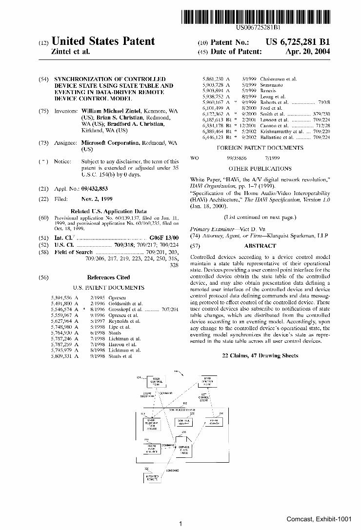
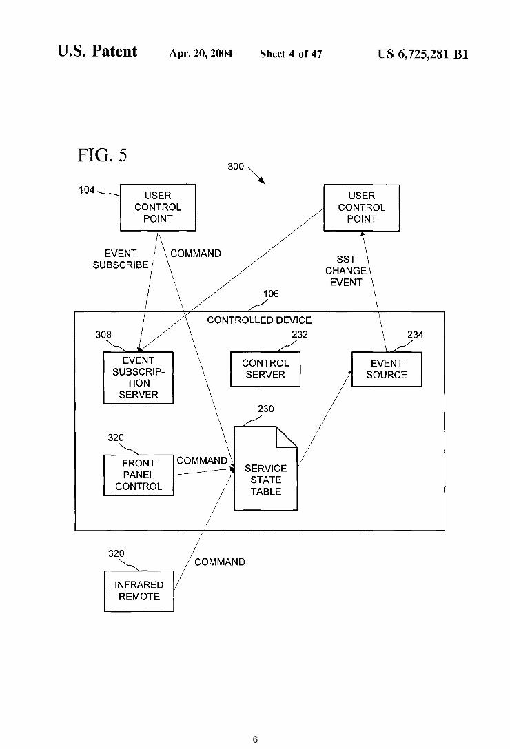
Controlled devices according to a device control model maintain a state table representative of their operational state. Devices providing a user control point interface for the controlled device obtain the state table of the controlled device, and may also obtain presentation data defining a remoted user interface of the controlled device and device control protocol data defining commands and data messaging protocol to effect control of the controlled device. These user control devices also subscribe to notifications of state table changes, which are distributed from the controlled device according to an eventing model. Accordingly, upon any change to the controlled device's operational state, the eventing model synchronizes the device's state as represented in the state table across all user control devices.
22 Claims, 47 Drawing Sheets
Comcast, Exhibit-10011
US 6, 725,281 Bl Page 2
01HER PUBLICATIONS
Anderson, "Fire Wire System Architecture: Second Edition, IEEE 1394a", chapters 1-4 (1999). Technical White Paper, "Jini Architectural Overview," Sun Microsystems, Inc. (1999). "Salutation Consortium Frequently Asked Questions," The Salutation Consortium, pp. 1-6 (prior to filing date), undated. "Salutation Architecture Specification (Part-1), Version 2.0c," The Salutation Consortium (Jul. 1, 1999). "How it works," Thalia, pp. 1-3 (prior to filing date), undated. "Sun Microsystems and Thalia Products Inc. to Collaborate to Co-Develop Network Software and Protocols for the Home, Results to Make Networked Appliances for the Home a Reality," Sunbeam Corporation, pp. 1-2 (2000). "Sunbeam Joins Microsoft in the Universal Plug and Play Forum to Establish A 'Universal' Smart Appliance Technology Standard," Sunbeam Corporation, pp. 1-2 (2000). "Time For Smart Talk Is Over, Sunbeam Trumps Small Appliance Industry with Smart Appliance Debut," Sunbeam Corporation, pp. 1-4 (2000). "Lonworks Core Technology," Echelon Corporation, pp. 1-2 (2000). "Underlying Protocol of Echelon's LONWORKS® Network Adopted as New ANSI Standard, Free Reference Implementation Available to Developers," Echelon Corporation, pp. 1-2 (2000). Handley et al., "SIP: Session Initiation Protocol," The Internet Society, pp. 1-130 (Aug. 6, 2000). Rosenberg et al., "SIP Extensions for Instant Messaging," Internet Engineering Task Force, pp. 1-30 (Jun. 15, 2000). Rosenbert et al., "SIP Extensions for Presence," Internet Engineering Task Force, pp. 1-77 (Jun. 15, 2000). Tsang et al., "Requirements for Networked Appliances: Wide-Area Access, Control, and Interworking," Internet Engineering Task Force, pp. 1-9 (Sep. 2000).
Tsang et al., "SIP Extensions for Communicating with Networked Appliances," Internet Engineering Task Force, pp. 1-9 (Nov. 2000).
Moyer et al., "Frame Draft for Networked Appliances using the Session Initiation Protocol," Internet Engineering Task Force, pp. 1-31 (Nov. 2000).
Marples, "Naming and Accessing Network Appliances using extensions to the Session Initial Protocol," SIP for Toaster, Telcordia Technologies (2000).
"Networked Appliance," AR Greenhouse, Telcordia Technologies, pp. 1-2 (Dec. 15, 2000).
Moyer et al., "SIP for Light Bulbs, Using SIP to Support Communication with Networked Appliances," Telcordis Technologies (Aug. 2, 2000).
Bennett et al., "Integrating Presence with Multi-media Communications," White Paper, Dynamicsoft., pp. 1-18 (2000).
Rosenberg et al., "An Application Server Architecture for Communications Services," White Paper, Dynamicsoft., pp. 1-13 (2000).
"EIB Technology," EIB (2000).
Freeman et al., "JavaSpaces™ Principles, Patterns, and Practice," Addison-Wesley Longman, Inc., Reading, Massachusetts (1999, Sun Microsystems, Inc.).
Arnold et al., "The Jini™ Specification," Addison-Wesley Longman, Inc., Reading, Massachusetts (1999, Sun Microsystems, Inc.).
Edwards, "Core Jini™, Second Edition," Prentice Hall PTR, Upper Saddle River, New Jersey (2001).
"Home Plug & Play™: CAL-based Interoperability for Home Systems," HomePNP™ Specification, Version 1.0, pp. 1-111, (Apr. 9, 1998).
* cited by examiner
2
U.S. Patent Apr. 20, 2004 Sheet 1 of 47 US 6, 725,281 Bl
FIG. 1 100~
MULTIPLE ---102 103--- MULTIPLE
FUNCTION DEVICE FUNCTION DEVICE
104 -1-- USER CONTROL
POINT
-1--CONTROLLED
106
DEVICE
FIG. 2 104
USER CONTROL POINT
DEVICE CONTROL PROTOCOLS
EVENTS
DEVICE CONTROL PROTOCOLS
EVENTS
USER CONTROL POINT
UPnP DEVICES BRIDGE
CONTROLLED DEVICE
CONTROLLED DEVICE
123
CONTROLLED 1--- :......-
DEVICE
USER 1--- ---CONTROL
POINT
/100
105
122
BRIDGED DEVICE
BRIDGED DEVICES
BRIDGED DEVICE
107
105
3
U.S. Patent
FIG. 3
DISCOVERY SERVER
DESCRIPTION SERVER
DESCRIP-TION
DOCUMENT
1 204-
Apr. 20, 2004 Sheet 2 of 47
200 202
~ 220 ROOT DEVICE 210
P~ENTATION I SER~ I SERVER
DEVICE 221 212 /
I SER~ I PRESENTATION SERVER
DEVICE 222 214 /
I SE;GE I PRESENTATION SERVER
1-
US 6, 725,281 Bl
211
I SER~E I 213
I SE~E I 215
I SE::CE I f 2d6
228 203---~---------==-------~~------~~---DEVICE 223 216 217
205
PRESEN~ION SE~E I S~ICE I SERVER
232
234
I I
CONTROL LOGIC
CONTROL SERVER
EVENT SOURCE
\ \
\ \
\
230
SERVICE STATE TABLE
4
U.S. Patent
FIG. 4
CLOCK
B DISCOVERY
SERVER
DESCRIPTION SERVER
DESCRIPTION
DOCUMENT
Apr. 20, 2004 Sheet 3 of 47 US 6, 725,281 Bl
251 250
\ TV NCR
DISCOVERY I POWER I B SERVER
DESCRIPTION TV
SERVER
B DESCRIP-
TION DOCUMENT
§CR~ 254---- T
5
U.S. Patent Apr. 20, 2004 Sheet 4 of 47
FIG. 5
104 USER CONTROL
POINT
300'X
EVENT SUBSCRIBE
COMMAND
232 ~
EVENT CONTROL SUBSCRIP- SERVER
TION SERVER
230
320
FRONT SERVICE PANEL STATE CONTROL TABLE
320 COMMAND
US 6, 725,281 Bl
USER CONTROL
POINT
SST CHANGE EVENT
EVENT SOURCE
6
U.S. Patent Apr. 20, 2004 Sheet 5 of 47 US 6, 725,281 Bl
FIG. 6 200 202
~ \ ROOT DEVICE
220 210 232 / / / PRESENT-
DISCOVERY ATION SERVICE I CONTROL DESCRIP-
SERVER SERVER ~ SERVER 20~ TION ~I URL DESCRIPTION DEVICE~ 216 I
SERVER /I 2~ PRESENT- SERVICE
[;t ATION SERVICE STATE TABLE V SERVER
DESCRIP- K TION r========-~. EVENT
DOCUMENT \ SUB-
( \ SCRIP-TION
J 2d6 \ SERVER
EVENT SINK \ URL \ EVENT
2 34 ---------1 SOURCE
7
U.S. Patent Apr. 20, 2004 Sheet 6 of 47 US 6, 725,281 Bl
FIG. 7 406
400
I 106 104 / / /
SERVICE DEFINITION CONTROLLED USER DEVICE CONTROL
POINT SERVICE + COMMAND
STATE SET TABLE DEFINITION
COMMANDS
2lo D 41s 226 -
/ ""'-7
404 I~ J\ " ~ SERVICE EMBEDDED DESCRIP- UPLOAD
CONTROL v TION v
DOCUMENT DECLARATION REHY-
232 ORATOR 402 / ~ SERVICE " CONTROL A
CONTROL IMPLEMENTED
SERVER SCP
v 'l PROTOCOL
( I
410
8
U.S. Patent Apr. 20, 2004 Sheet 7 of 47
FIG. 8
USER CONTROL POINT
APPLICATIONS OBJECT INTEGRATION INTERFACES
416
CONTRACT • PACKETS • REQUEST/
RESPONSE PATTERNS
ICLOCK
REHYDRATOR
• PROTOCOLS
DESCRIPTION
DOCUMENT
CONTROLLED DEVICE (E.G., CLOCK)
US 6, 725,281 Bl
DATA PACKETS
CONTROL SERVER
104
9
U.S. Patent
FIG. 9
Apr. 20, 2004 Sheet 8 of 47 US 6, 725,281 Bl
440
\
CreateServiceObject()
REHYDRATOR
DEVICE FINDER
410
450
QueryStateVariable() lnvokeAction()
464
SERVICE OBJECT
QueryStateVariable()
t-+--o IUPnPlnvokeAction() Service
10
U.S. Patent Apr. 20, 2004 Sheet 9 of 47 US 6, 725,281 Bl
FIG. 10 104 106
~ / USER CONTROL POINT CONTROLLED DEVICE
DISCOVERY SSDP DISCOVERY
CLIENT SERVER 226 /
DESCRIP- DESCRIP-DESCRIP- PESCRIP TION CLIENT TION
TION ,..---TION
SERVER DOCUMENT
~-VISUAL
220 228
~ NAVIGATION
----------------" PRESENT-
BROWSER~ ATION ---WEB USER
~ __.-- SERVER INTERFACE
USER~ INTER- 410 232
I FACE ---~- --- r--/--------I
I BROWSER REHY- CONTROL CONTROL I I CONTROL h ORATOR
SCP SERVER LOGIC I
I I I I I
APPLICA- EVENT EVENT SERVICE I I ~
TION SINK UPnP SOURCE STATE I I EVENTS TABLE I I ~34 I I 230
I I __________ PE~ERVIC~---------~
11
U.S. Patent Apr. 20, 2004 Sheet 10 of 47 US 6, 725,281 Bl
FIG 11 104 106 . / /
USER CONTROL POINT CONTROLLED DEVICE
DISCOVERY SSDP
DISCOVERY CLIENT SERVER 226
~
DESCRIP- DESCRIP-DESCRIP- DESCRIP TION CLIENT TION
TION ~ TION SERVER DOCUMENT
~8 ,-------------1-------------I EVENT SUB- EVENT I I _______. SUBSCRIP SCRIBE SUBSCRIP I
-TION (EVENT -TION \ I I CLIENT SINK SERVER I
I APPLICA- URL)
SERVICE : I
TION
EVENT EVENT I ..-
SINK NOTIFY SOURCE STATE I I (EVENT) TABLE I I
')34 230 I I I_---------~ R SERVI< E I
---__________ _J
12
U.S. Patent Apr. 20,2004 Sheet 11 of 47 US 6, 725,281 Bl
FIG. 12 COMBINED BRIDGE AND USER CONTROL POINT
DESCRIPTION
DOCUMENT
DISCOVERY SERVER
DESCRIPTION
SERVER
STATE CHANGE EVENTS
USER CONTROL
POINT
230 /
SERVICE CONTROL
BRIDGE APPLICA
TION
STATE~~'~ TABLE L-/____,_.....J - - ~!_
EVENT SOURCE
CONTROL SERVER
COMMANDS
USER CONTROL
POINT
REHYDRATOR
- - -1- _§P_I__
SERVICE PROVIDER
I I
BRIDGED DEVICE
13
U.S. Patent Apr. 20,2004 Sheet 12 of 47
FIG. 13 USER CONTROL PO INT
DISCOVERY CLIENT
I {
(PARSE DESCRIPTION, ISSU
REQUESTS FOR ADDITIONAL
INFORMATION)
l DEVICE
DESCRIPTION SERVICE
I
E
(CONFIGURE REHYDRA TOR, ADD
DEVICE ICON TO USER INTERFACE)
' VISUAL NAVIGATION
I
r
'-
(USER SELECTS DEV ICON)
ICE
+ BROWSER
I (EMBEDDED SCRIP
{ TIN YS WEB PAGE DISPLA
DEVICE Ul; SCRIP CALLS REHYDRA T TO INTERACT WIT
DEVICE)
T OR H
' { REHYDRATOR
co SSDP DISCOVERY REQUEST
} DISCOVERY RESPONSE (URL)
GET(DESCRIPTION URL) -., RESPONSE(UPnP
DESCRIPTION)
GET ICON
RESPONSE
GET NAME
RESPONSE
GET SCPO
RESPONSE
,_..
GET(PRESENTATION URL)
} RESPONSE
GET/PUT(CONTROL URL)
} RESPONSE
US 6, 725,281 Bl
NTROLLED DEVICE
DISCOVERY SERVER
DESCRIPTION SERVER
PRESENTATION (WEB) SERVER
CONTROL SERVER
14
U.S. Patent Apr. 20,2004
FIG. 14 root
Sheet 13 of 47
specVersionMajor specVersionMinor URLBase manufacturer manufacturerURL model Name modeiNumber model Description modeiURL UPC serial Number device
UDN friendlyName
device Type presentationURL icon list
icon
icon icon
size color depth image Type imageURL
service service Type controiURL eventSubURL SCPO
service service device
device device
service service device
service
US 6, 725,281 Bl
15
U.S. Patent Apr. 20,2004 Sheet 14 of 47 US 6, 725,281 Bl
FIG. 15 <device>
<icon list> <icon>
<size> 16</size> <color>O</color> <depth>B</depth> <imageType>PNG</imageType> <image>"http://device.local/iconpath/icon16bw.png"</image>
</icon> <icon>
<size>32</size> <color>O</color> <depth>B</depth> <imageType>PNG</imageType> <image>"http://device.local/iconpath/icon32bw.png"</image>
</icon> <icon>
<size>48</size> <color>O</color> <depth>B</depth> <imageType>PNG</imageType> <image>"http://device.local/iconpath/icon48bw. png"</image>
</icon> <icon>
<size>16</size> <color>1 </color> <depth>8</depth> <imageType>PNG</imageType> <image>"http://device.local/iconpath/icon16c.png"</image>
</icon><device> <icon>
<size>32</size> <color>O</color> <depth>8</depth> <imageType>PNG</imageType> < image>"http :1/device.locallicon path/icon32c. png"</i mage>
</icon> <icon>
<size>48</size> <color>O</color> <depth>8</depth> <imageType>PNG<IimageType> <image>"http://device.local/iconpath/icon48c. png"</image>
</icon>
</icon list>
</device>
16
U.S. Patent Apr. 20,2004 Sheet 15 of 47 US 6, 725,281 Bl
FIG. 16
<?xml version="1.0"?> <scpd xmlns="x-schema:scpdl-schema.xml">
<service StateTable> <state Variable>
<name>currentChannel</name> <dataType>number</dataType> <allowedValueRange>
<minimum>O</minimum> <maximum>55</maximum> <step>1 </step>
</allowedValueRange> </state Variable>
</serviceState Table>
<action list> <action>
<name>ChanneiUp</name> </action>
<action> <name>ChanneiDown</name>
</action>
<action> <name>SetChannel</name> <argument>
<name>newChannel</name> <relatedStateVariable>
currentChannel </relatedStateVariable>
</argument> </action>
</action List> </scpd>
17
U.S. Patent Apr. 20,2004
FIG. 17
<contract> <protocol id="protocoiDef'>
<HTTP version="1.1 "> <URL></URL> <M-POST>
Sheet 16 of 47 US 6, 725,281 Bl
<MAN>http://www. microsoft. com/protocols/ext/XOAP</MAN> <IM-POST> <HEADER name="Content-Type" value="text/xml" />
<!--Need to put in extension headers here-> </HTTP>
</protocol>
<RequestResponse name="queryStateVariable"> <protocol is="protocoiDef'> <in is="queryStateVariable"> <out is="queryStateVariableResponse"> <error is="queryStateVariableResponse">
</RequestResponse>
<RequestResponse name="invokeAction"> <protocol is="protocoiDef'> <in is="SerializedStream"> <out is="invokeActionResponse"> <error is="invokeActionResponse">
</Req uestResponse>
<Schema name="upnp_scpdl" xmlns="urn :schemas-microsoft-com:xml-data" xm Ins: dt="urn:schemas-microsoft-com: datatypes">
<!--Common-->
<EiementType name="_return" content="textOnly" dt:type="string" /> <EiementType name="_fault" content="textOnly" dt:type="string" />
<!--Query State Variable Call-->
<EiementType name="variableName" content="textOnly" dt:type="string" />
<EiementType name="queryStateVariable" content="eltOnly" model="closed"> <element type="variableName" />
</EiementType>
<!-- Query State Variable Response -->
18
U.S. Patent Apr. 20,2004 Sheet 17 of 47 US 6, 725,281 Bl
FIG. 18
<EiementType name="queryStateVariableResponse" content="eltOnly" model=" closed">
<group order="one"> <element type="_return"> <element type="_fault">
</group> </EiementType>
<!--Invoke Action Call-->
<AttributeType name="main" dt:type="idref' /> <Attribute Type name="headers" dt:type="idref' /> <Attribute Type name="id" dt:type="id" />
<EiementType name="sequenceNumber'' content="textOnly" dt:type="int"> <AttrbuteType name="dt" dt:type="string" dt:values="int" />
<attribute type="dt" /> </EiementType>
<EiementType name="headers" content="eltOnly" model="closed" <attribute type="id" required="yes" /> <element type="sequenceNumber" />
</EiementType>
<EiementType name="actionName" content="textOnly" dt:type="string" /> <EiementType name="actionArg" content="textOnly" dt:type="string" />
<EiementType name="invokeAction" content="eltOnly" model="closed"> <attribute type="id" required="yes" />
<element type="actionName"> <element type="actionArg" minOccurs="O" maxOccurs="*">
</EiementType>
19
U.S. Patent Apr. 20, 2004 Sheet 18 of 47 US 6, 725,281 Bl
FIG. 19
<EiementType name="SerializedStream" content="eltOnly" model="closed"> <attribute type="main" required="yes" /> <attribute type="headers" required="yes" />
<element type=" headers"> <element type="invokeAction">
</EiementType>
<!--Invoke Action Response-->
<EiementType name="invokeActionResponse" content="eltOnly" model="closed"> <group order="one">
<element type="_return"> <element type="_fault">
</group> </EiementType>
</Schema> </contract>
20
U.S. Patent Apr. 20, 2004 Sheet 19 of 47
FIG. 20
<?xml version="1.0"?> <Schema name="upnp_scpdl"
xmlns="urn:schemas-microsoft-com:xml-data" xmlns:dt="urn:schemas-microsoft-com:datatypes">
<!--Common Elements and Attributes-->
US 6, 725,281 Bl
<EiementType name="name" content="textOnly" dt:type="string" />
<!--Service State Table-->
<EiementType name="minimum" content="textOnly" dt:type="number" /> <EiementType name="maximum" content="textOnly" dt:type="number'' /> <EiementType name="step" content="textOnly" dt:type="number" />
<EiementType name="allowedValueRange" content="eltOnly" model="closed"> <element type="minimum" /> <element type="maximum" /> <element type="step" minOccurs="O" />
</EiementType>
<EiementType name="allowedValue" content="textOnly" />
<EiementType name="allowedValueList" content="eltOnly" model="closed"> <element type="allowedValue" min0ccurs="1" maxOccurs="*" />
</EiementType>
<EiementType name="dataType" content="textOnly" dt:type="string" />
<EiementType name="stateVariable" content="eltOnly" model="closed"> <element type="name" />
21

U.S. Patent Apr. 20, 2004 Sheet 20 of 47
FIG. 21
<element type="dataType" />
<group minOccurs="O" max0ccurs="1" order="one"> <element type="allowedValueRange" /> <element type="allowedValuelist" />
</group> </EiementType>
US 6, 725,281 Bl
<EiementType name="deviceStateTable" content="eltOnly" model="closed"> <element type="stateVariable" min0ccurs="1" maxOccurs="*" />
</EiementType>
<!--Action List-->
<EiementType name="relatedStateVariable" content="textOnly" dt:type="string" />
<EiementType name="argument" content="eltOnly" model="closed"> <element type="name" /> <element type="relatedStateVariable" />
</EiementType>
<EiementType name="action" content="eltOnly" model="closed"> <element type="name" /> <element type="argument" minOccurs="O" maxOccurs="*" />
</Element Type>
<EiementType name="actionlist" content="eltOnly" model="closed"> <element type="action" minOccurs="O" maxOccurs="*" />
</EiementType>
< !-- Root Element ->
<EiementType name="dcpd" content="eltOnly" model="closed"> <element type="deviceStateTable" /> <element type="actionlist" />
</EiementType> </Schema>
22
U.S. Patent Apr. 20, 2004 Sheet 21 of 47 US 6, 725,281 Bl
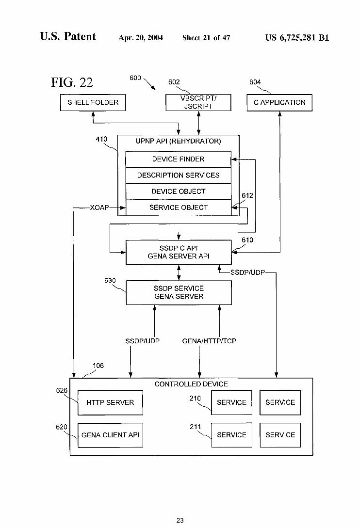
FIG 22 600~ 602 604 . ~ ~
I SHELL FOLDER I VBSCRIPT/
I c APPLICATION I JSCRIPT
t !l !l
• r 410 UPNP API (REHYDRA TOR) ~
DEVICE FINDER
DESCRIPTION SERVICES
DEVICE OBJECT 612
-XOAP-r-. SERVICE OBJECT ~v
~ t 610
~ SSDPCAPI v
GENA SERVER API
t LssDP/UDP-630 ~ SSDP SERVICE
GENA SERVER
SSDP/UDP GENAIHTTP/TCP
106
CONTROLLED DEVICE 626
21~ I SERVICE I HTTP SERVER
GENA CLIENT API 21~ 1 I SERVICE
23
U.S. Patent Apr. 20, 2004 Sheet 22 of 47
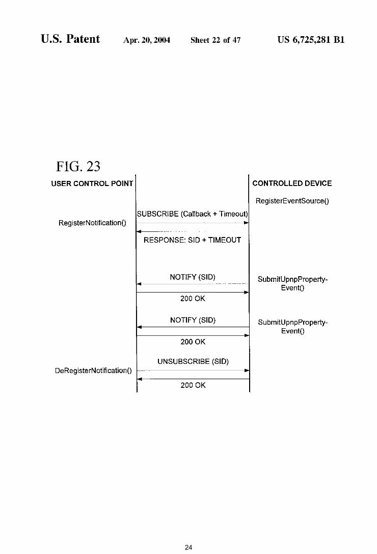
FIG. 23 USER CONTROL POINT
SUBSCRIBE (Callback + Timeout) RegisterNotification()
RESPONSE: SID +TIMEOUT
NOTIFY (SID)
200 OK
NOTIFY (SID)
2000K
UNSUBSCRIBE (SID) DeRegisterNotification()
- 200 OK
US 6, 725,281 Bl
CONTROLLED DEVICE
RegisterEventSource()
SubmitUpnpPropertyEvent()
SubmitUpnpPropertyEvent()
24
U.S. Patent Apr. 20,2004 Sheet 23 of 47 US 6, 725,281 Bl
FIG. 24
PERSONAL COMPUTER 820 ,...--------,
PROCESSING 821 UNIT
832
833
834
SYSTEM MEMORY
RAM
ROM
INTERFACE
INTERFACE
INTERFACE
VIDEO ADAPTER
SERIAL PORT
INTERFACE
NETWORK ADAPTER
822
I I I
1- OPERATING- ~835 I SYSTEM I _______ J
r-------1 1 APPLICATIONS 1--- 836
I -------J --""' -- -//: ~-MODULES-~837
L-------J
/ /
CD-ROM DRIVE
DISK
848
/
/ /
/
854
/ I r-------1 I DATA 1---838 • _______ J
827
828
847
830
831 KEYBOARD
MOUSE
852 842
851
25
U.S. Patent Apr. 20, 2004 Sheet 24 of 47 US 6, 725,281 Bl
FIG. 25
900 ---- EMBEDDED COMPUTING DEVICE
MEMORY ~ PROCESSING
~ OPERATIONAL
UNIT CIRCUITRY
I ~ I 904 902
NETWORK 906
908---.... ADAPTER
910----- NETWORK MEDIA
FIG. 26 920
~ 925 I
922 ---- DEVICE FUNCTIONS I 924 --l SIMPLE DISCOVERY I HTTP
9::~ 930
IJ
AUTONET TCPIIPSTACK I DHCP
910'--i PHYSICAL MEDIA I
26
U.S. Patent
FIG. 27 934
900
) EMBEDDED COMPUTING
DEVICE
FIG. 28
900
)
\
940
\ EMBEDDED COMPUTING
DEVICE
950
) CLIENT DEVICE
Apr. 20, 2004 Sheet 25 of 47
DHCP BROADCAST
(TIMEOUT)
ASSIGN AUTONET ADDRESS
DNS NAME MULTICAST
ANNOUNCE SERVICE
(TIMEOUT- WAIT FOR RESPONSE)
\ DISCOVER SERVICE I
I RESPONSE TO DISCOVER > ( ___ G_E~T~H_TT_P_X_M_L ___ I
XML DEVICE DESCRIPTION ~
DHCP BROADCAST
< ADDRESS FROM DHCP SERVER
DNS UNICAST TO DNS SERVER
\ LISTENER GET HTTP XML
I DIRECTORY UPDATED BY LISTENER
I DEVICE SPECIFIC NEGOTIATION
LDAP QUERY DIRECTORY-=>
US 6, 725,281 Bl
936
NETWORK SERVER
; 936
27
U.S. Patent Apr. 20, 2004 Sheet 26 of 47 US 6, 725,281 Bl
FIG. 29 950
~ 955 956 952
954
I I - I I APPLICATIONS
-l SIMPLE DISCOVERY I XML LDAP ADS I
gss~~==============T=C=P=/I=P=S=TA=C=K==============~'WI:::CK 960-lL------------------NI_c ________________ ~l
28
U.S. Patent Apr. 20, 2004 Sheet 27 of 47 US 6, 725,281 Bl
FIG. 30 1000
\ PVC 1030
POWER
TELEPHONE LIGHTING
1032 ..--..I....----, 1004
100 PC PC
USB 1006 USB
1016 1017
MODEM
1012
XDSL
1011
TELEPHONE ~+-------'
L.....--------r-1 010
1051
REMOTE CONTROL
1041
IEEE 1394
GAME
PC
H/PC
IRDA
DIGITAL
.___c_A_M_E_RA_.,.....1 021
PRINTER
AUDIO
1020
1015
1014
29
U.S. Patent
FIG. 31
[ object, uuid(<foo>), dual,
Apr. 20, 2004
helpstring ("I U PN P Device interface"), pointer_default(unique) ]
interface IUPNPDevice: !Dispatch {
Sheet 28 of 47 US 6, 725,281 Bl
[propget, id(DISPID_UPNPDEVICE_DESCRIPTIONDOCUMENT), helpstring("returns the document from which the properties of this device are
being read")] HRESUL T DescriptionDocument([restricted, hidden, out, retval]
IUPNPDescriptionDocument ** ppuddDocument); purpose: returns the document from which the properties of this device are
being read. parameters: ppuddDocument, A reference to the description document
object from which data about the device is being read. This must be freed when no longer needed.
return values: S_OK, ppuddDocument is a refernce to the device's description document.
[propget, id(DISPID _ UPNPDEVICE _ISROOTDEVICE), helpstring("denotes whether the physical location information of this device can
be set")] HRESUL T lsRootDevice([out, retval] VARIANT _BOOL * pvarb);
parameters: pvarb, the address of a VARIANT _BOOL that will receive the value of VARIANT_ TRUE if the current device is the topmost device in the device tree, and will receive the value of VARIANT _FALSE otherwise.
return values: S_OK, varb is set to the appropriate value note: if a device is a root device, calls RootDevice() or ParentDevice() will
return NULL
[propget, id(DISPID _ UPNPDEVICE_ROOT), helpstring("returns the top device in the device tree")] HRESULT RootDevice([out, retval] IUPNPDevice ** ppudDeviceRoot);
purpose: returns the top device in the device tree
30
U.S. Patent Apr. 20, 2004 Sheet 29 of 47 US 6, 725,281 Bl
FIG. 32
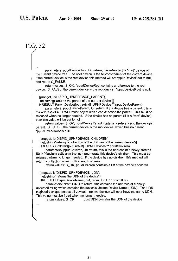
parameters: ppudDeviceRoot, On return, this refers to the "root" device of the current device tree. The root device is the topmost parent of the current device. If the current device is the root device this method will set *ppudDeviceRoot to null, and return S_FALSE.
return values: S_OK, *ppudDeviceRoot contains a reference to the root device. S_FALSE, the current device is the root device. *ppudDeviceRoot is null.
[propget, id(DISPID_UPNPDEVICE_PARENT), helpstring("returns the parent of the current device")]
HRESULT ParentDevice([out, retval] IUPNPDevice ** ppudDeviceParent); parameters: ppudDeviceParent, On return, if the device has a parent, this is
the address of a IUPNPDevice object which can describe the parent. This must be released when no longer needed. If the device has no parent (it is a "root" device), than this value will be set to null.
return values: S_OK, ppudDeviceParent contains a reference to the device's parent. S_FALSE, the current device is the root device, which has no parent. *ppudDeviceRoot is null.
[propget, id(DISPID _ UPNPDEVICE_CHILDREN), helpstring("returns a collection of the children of the current device")]
HRESUL T Children([ out, retval] IUPNPDevices ** ppudChildren); parameters: ppudChildren, On return, this is the address of a newly-created
IUPNPDevices collection that can enumerate this device's children. This must be released when no longer needed. If the device has no children, this method will return a collection object with a length of zero.
return values: S_OK, ppudChildren contains a list of the device's children.
[propget, id(DISPID _ UPNPDEVICE_UDN), helpstring("returns the UDN of the device")]
HRESUL T UniqueDeviceName([out, retval] BSTR * pbstrUDN); parameters: pbstrUDN, On return, this contains the address of a newly
allocated string which contains the device's Unique Device Name (UDN). The UDN is globally unique across all devices- no two devices will ever have the same UDN. This value must be freed when no longer needed.
return values: S_ OK pbstrUDN contains the UDN of the device
31

U.S. Patent Apr. 20,2004 Sheet 30 of 47
FIG. 33
[propget, id(DISPID _ UPNPDEVICE_DISPLA YNAME), helpstring("returns the (optional) display name of the device")] HRESUL T DisplayName([out, retval] BSTR * pbstrDisplayName);
US 6, 725,281 Bl
parameters: pbstrDisplayName, On return, this contains the address of the device's display name. This value must be freed when no longer needed. If the device does not specify a display name, this parameter will be set to null.
return values: S_OK, bstrDisplayName contains the display name of the device. pbstrDisplayName must be freed. S_FALSE, the device did not specify a display name. *pbstrDisplayName is set to null.
note: it is possible for multiple devices to have the same display name. Applications should use UniqueDeviceName() to determine if two device objects refer to the same device.
[propget, id(DISPID_UPNPDEVICE_CANSETDISPLAYNAME), helpstring("denotes whether the physical location information of this device can
be set")] HRESULT CanSetDisplayName([out, retval] VARIANT_BOOL * pvarb);
parameters: pvarb, the address of a VARIANT_BOOL. This is true (!=0) on return when the device's display name can be set (via SetDisplayName)
return values: S _OK varb is set to the appropriate value
[id(DISPID _ UPNPDEVICE _ SETDISPLA YNAME), helpstring("sets the display name on the device")]
HRESUL T SetDisplayName([in] BSTR bstrDisplayName); parameters: bstrDisplayName, the value to set the device's display name to. return values: S_OK, varb is set to the appropriate value. note: On success, this method sets the display name used by a device.
Note that this method changes the display name on the device itself, not simply on the local object. This will block while the name is being set. Additionally, this change will be made on the device alone, and will not be reflected in the current device object. After a successful call to this method, DisplayName will continue to return the 'old' value). To read the device's current name, the caller must re-load the device's description.
[propget, id(DISPID _ UPNPDEVICE_DEVICETYPE),
32

U.S. Patent Apr. 20, 2004 Sheet 31 of 47
FIG. 34
helpstring("returns the device type URI")] HRESUL T Type([ out, retval] BSTR * pbstrType);
US 6, 725,281 Bl
parameters: pbstrType, On return, this contains the address of a newly-allocated string containing the device's type URI. This value must be freed when no longer needed.
return values: S_ OK, bstrType contains the type URI of the device, and must be freed when no longer needed.
[propget, id(DISPID_UPNPDEVICE_SERVICES), helpstring("returns the collection of services exposed by the device")]
HRESULT Services([out, retval] IUPNPServices ** ppusServices); parameters: ppusServices, On return, this is the address of a newly-created
IUPNPServices collection that can enumerate the services exposed by the device. This must be released when no longer needed. If the device exposes no services, this method will return a collection object with a length of zero.
return values: S_OK, pusServices contains a list of the device's children.
[propget, id(DISPID_UPNPDEVICE_SERVICEIDENTIFIER), helpstring("returns the (optional) service identifier of the device")] HRESULT Serviceldentifier([out, retval] BSTR * pbstrServiceiD );
parameters: pbstrServiceiD, On return, this contains the address of a newlyallocated string containing the contents of the device's Service Identifier element, if the device specifies one. This value must be freed when no longer needed. If the device does not specify a Service Identifier value, this parameter will be set to null.
return value: S_OK, bstrServiceiD contains the service identifier of the device. pbstrServiceiD must be freed. S_FALSE, the device did not specify a service identifier. *pbstrServiceiD is set to null.
note having a Serviceldentifier is mutually exclusive with having services. Any device will either have a list of services or a Serviceldentifier, but not both.
[id(DISPID _ UPNPDEVICEDESCRIPTION_LOADSMALLICON), helpstring("loads a small (titlebar-sized) icon representing the device, encoded in the
specified format")] HRESUL T LoadSmalllcon([in] BSTR bstrEncodingFormat, [out, retval] BSTR * pbstrlconURL);
parameters:
33
U.S. Patent Apr. 20, 2004 Sheet 32 of 47 US 6, 725,281 Bl
FIG. 35
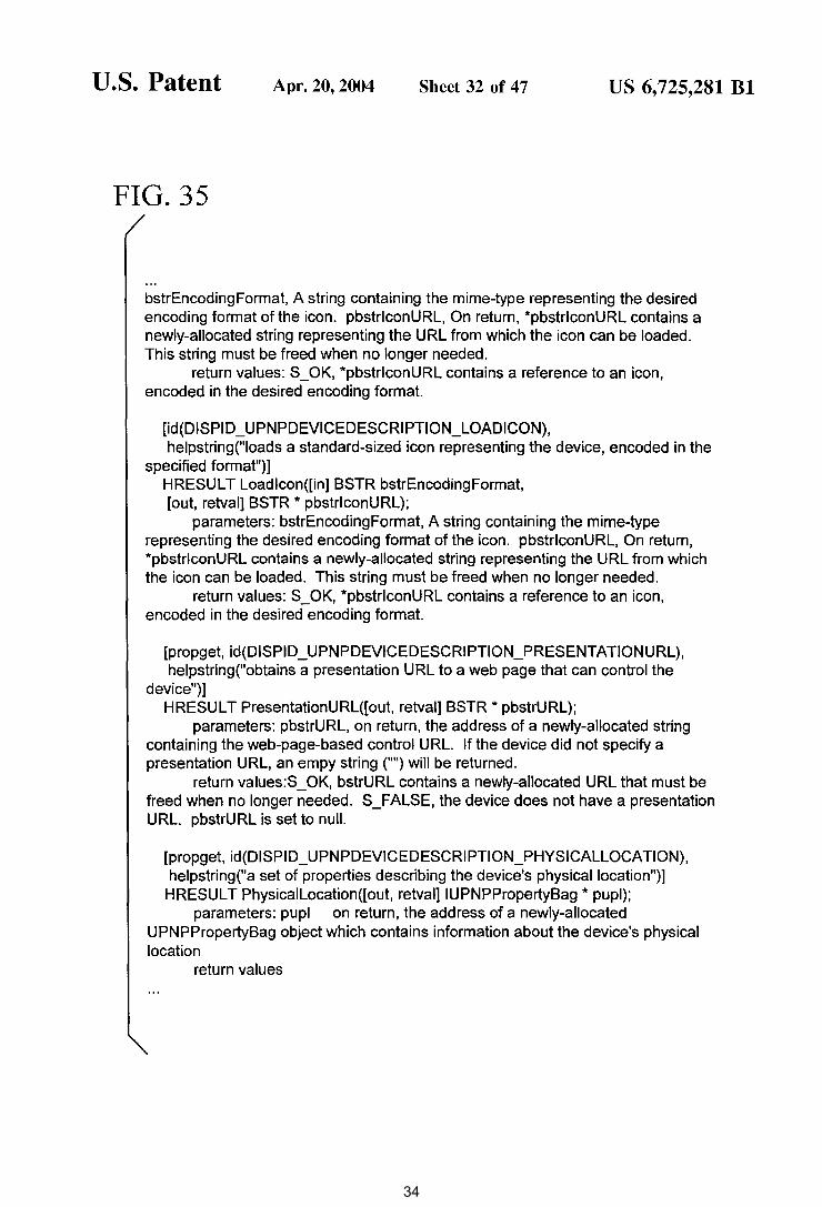
bstrEncodingFormat, A string containing the mime-type representing the desired encoding format of the icon. pbstrlconURL, On return, *pbstrlconURL contains a newly-allocated string representing the URL from which the icon can be loaded. This string must be freed when no longer needed.
return values: S_OK, *pbstrlconURL contains a reference to an icon, encoded in the desired encoding format.
[id(DISPID_UPNPDEVICEDESCRIPTION_LOADICON), helpstring("loads a standard-sized icon representing the device, encoded in the
specified format")] HRESUL T Loadlcon([in] BSTR bstrEncodingFormat, [out, retval] BSTR * pbstrlconURL);
parameters: bstrEncodingFormat, A string containing the mime-type representing the desired encoding format of the icon. pbstrlconURL, On return, *pbstrlconURL contains a newly-allocated string representing the URL from which the icon can be loaded. This string must be freed when no longer needed.
return values: S_OK, *pbstrlconURL contains a reference to an icon, encoded in the desired encoding format.
[propget, id(DISPID_UPNPDEVICEDESCRIPTION_PRESENTATIONURL), helpstring("obtains a presentation URL to a web page that can control the
device")] HRESULT PresentationURL([out, retval] BSTR * pbstrURL);
parameters: pbstrURL, on return, the address of a newly-allocated string containing the web-page-based control URL. If the device did not specify a presentation URL, an empy string ("") will be returned.
return values:S_OK, bstrURL contains a newly-allocated URL that must be freed when no longer needed. S_FALSE, the device does not have a presentation URL. pbstrURL is set to null.
[propget, id(DISPID _ UPNPDEVICEDESCRIPTION_PHYSICALLOCATION), helpstring("a set of properties describing the device's physical location")]
HRESUL T Physicallocation([out, retvai]IUPNPPropertyBag * pupl); parameters: pupl on return, the address of a newly-allocated
UPNPPropertyBag object which contains information about the device's physical location
return values
34
U.S. Patent Apr. 20, 2004 Sheet 33 of 47 US 6, 725,281 Bl
FIG. 36
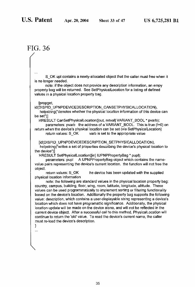
S_OK upl contains a newly-allocated object that the caller must free when it is no longer needed.
note: if the object does not provide any description information, an empy property bag will be returned. See SetPhysicallocation for a listing of defined values in a physical location property bag.
[propget, id(DISPI D _ UPNPDEVICEDESCRI PTION_ CANSETPHYSICALLOCATION),
helpstring("denotes whether the physical location information of this device can be set")]
HRESUL T CanSetPhysicallocation([out, retval] VARIANT _BOOL * pvarb); parameters: pvarb the address of a VARIANT_BOOL. This is true (!=0) on
return when the device's physical location can be set (via SetPhysicallocation) return values: S_OK varb is set to the appropriate value
[id(DISPI D _ UPNPDEVICEDESCRIPTION _ SETPHYSICALLOCATION), helpstring("writes a set of properties describing the device's physical location to
the device")) HRESUL T SetPhysicallocation([in] IUPNPPropertyBag * pupl);
parameters: pupl A UPNPPropertyBag object which contains the name-value pairs representing the device's current location. the function will not free the object.
return values: S_OK he device has been updated with the supplied physical location information
note: the following are standard values in the physical location property bag: country, campus, building, floor, wing, room, latitude, longitude, altitude. These values can be used programmatically to implement sorting or filtering functionality based on the device's location. Additionally the property bag supports the following value: description, which contains a user-displayable string representing a device's location which does not have programattic significance. Additionally, the physical location update will be made on the device alone, and will not be reflected in the current device object. After a successful call to this method, Physicallocation will continue to return the 'old' value. To read the device's current name, the caller must re-load the device's description. }
35
U.S. Patent Apr. 20, 2004 Sheet 34 of 47
FIG. 37
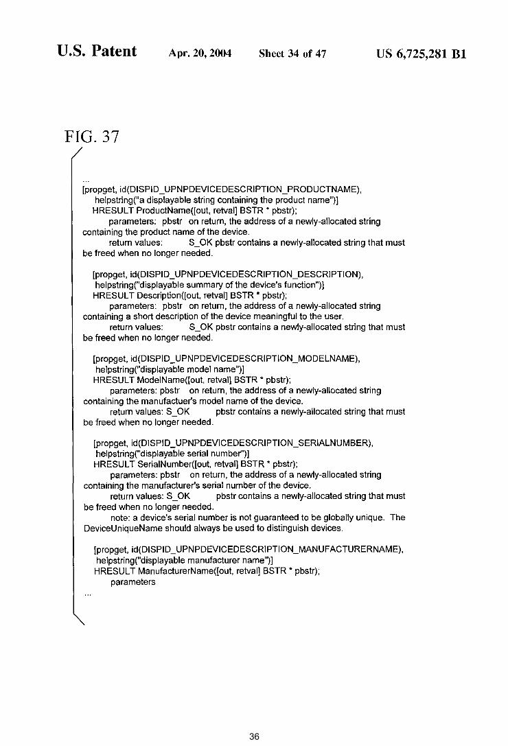
[propget, id(DISPID_UPNPDEVICEDESCRIPTION_PRODUCTNAME), helpstring("a displayable string containing the product name")]
HRESUL T ProductName([out, retval] BSTR * pbstr);
US 6, 725,281 Bl
parameters: pbstr on return, the address of a newly-allocated string containing the product name of the device.
return values: S_OK pbstr contains a newly-allocated string that must be freed when no longer needed.
[propget, id(DISPID_UPNPDEVICEDESCRIPTION_DESCRIPTION), helpstring("displayable summary of the device's function")] HRESUL T Description([ out, retval] BSTR * pbstr);
parameters: pbstr on return, the address of a newly-allocated string containing a short description of the device meaningful to the user.
return values: S_OK pbstr contains a newly-allocated string that must be freed when no longer needed.
[propget, id(DISPID_UPNPDEVICEDESCRIPTION_MODELNAME), helpstring("displayable model name")]
HRESUL T ModeiName([out, retval] BSTR * pbstr); parameters: pbstr on return, the address of a newly-allocated string
containing the manufactuer's model name of the device. return values: S_OK pbstr contains a newly-allocated string that must
be freed when no longer needed.
[propget, id(DISPID_UPNPDEVICEDESCRIPTION_SERIALNUMBER), helpstring("displayable serial number")]
HRESUL T SeriaiNumber([out, retval] BSTR * pbstr); parameters: pbstr on return, the address of a newly-allocated string
containing the manufacturer's serial number of the device. return values: S_OK pbstr contains a newly-allocated string that must
be freed when no longer needed. note: a device's serial number is not guaranteed to be globally unique. The
DeviceUniqueName should always be used to distinguish devices.
[propget, id(DISPID_UPNPDEVICEDESCRIPTION_MANUFACTURERNAME), helpstring("displayable manufacturer name")]
HRESUL T ManufacturerName([out, retval] BSTR * pbstr); parameters
36
U.S. Patent Apr. 20, 2004 Sheet 35 of 47 US 6, 725,281 Bl
FIG. 38
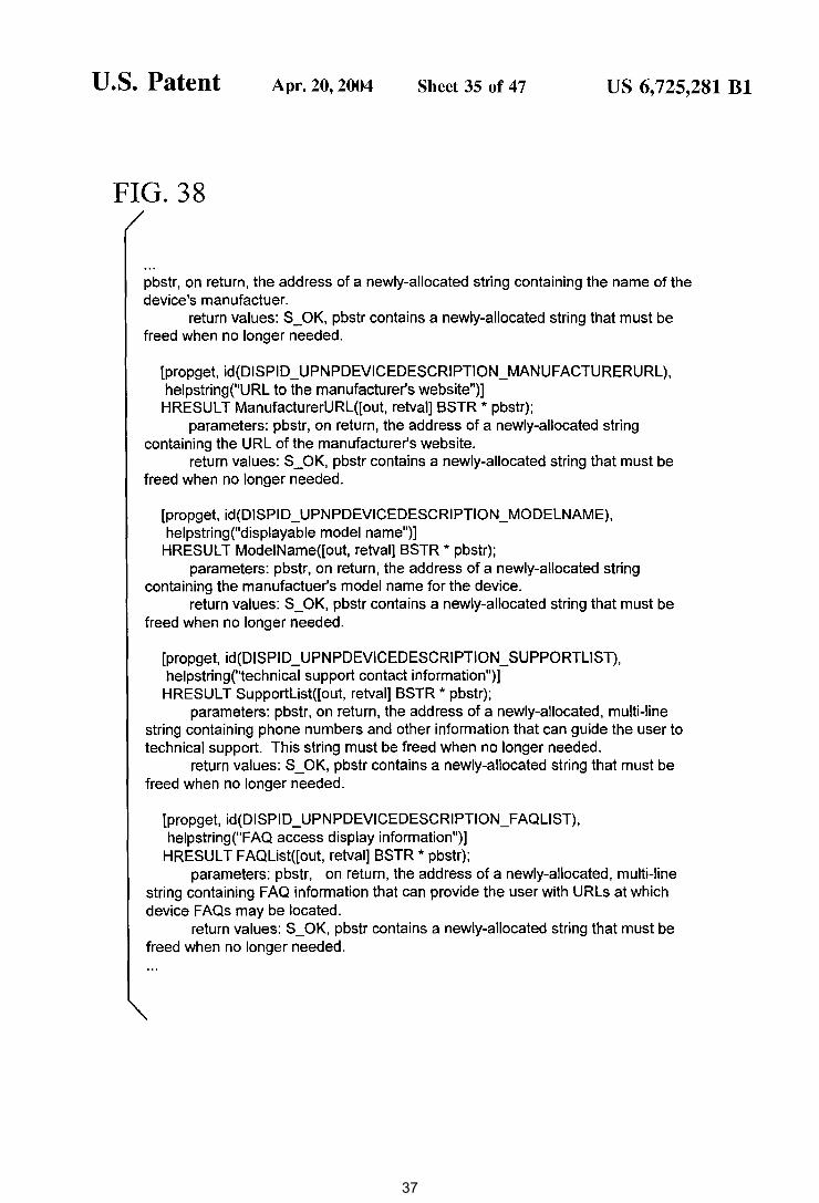
pbstr, on return, the address of a newly-allocated string containing the name of the device's manufactuer.
return values: S_OK, pbstr contains a newly-allocated string that must be freed when no longer needed.
[propget, id(DISPID_UPNPDEVICEDESCRIPTION_MANUFACTURERURL), helpstring("URL to the manufacturer's website")] HRESULT ManufacturerURL([out, retval] BSTR * pbstr);
parameters: pbstr, on return, the address of a newly-allocated string containing the URL of the manufacturer's website.
return values: S_OK, pbstr contains a newly-allocated string that must be freed when no longer needed.
[propget, id(DISPID_UPNPDEVICEDESCRIPTION_MODELNAME), helpstring("displayable model name")]
HRESULT ModeiName([out, retval] BSTR * pbstr); parameters: pbstr, on return, the address of a newly-allocated string
containing the manufactuer's model name for the device. return values: S_OK, pbstr contains a newly-allocated string that must be
freed when no longer needed.
[propget, id(DISPID _ UPNPDEVICEDESCRIPTION _ SUPPORTLIST), helpstring("technical support contact information")] HRESULT Supportlist([out, retval] BSTR * pbstr);
parameters: pbstr, on return, the address of a newly-allocated, multi-line string containing phone numbers and other information that can guide the user to technical support. This string must be freed when no longer needed.
return values: S_OK, pbstr contains a newly-allocated string that must be freed when no longer needed.
[propget, id(DISPID _ UPNPDEVICEDESCRIPTION _FAQLIST), helpstring("FAQ access display information")]
HRESUL T FAQList([out, retval] BSTR * pbstr); parameters: pbstr, on return, the address of a newly-allocated, multi-line
string containing FAQ information that can provide the user with URLs at which device FAQs may be located.
return values: S _OK, pbstr contains a newly-allocated string that must be freed when no longer needed.
37
U.S. Patent Apr. 20, 2004 Sheet 36 of 47 US 6, 725,281 Bl
FIG. 39
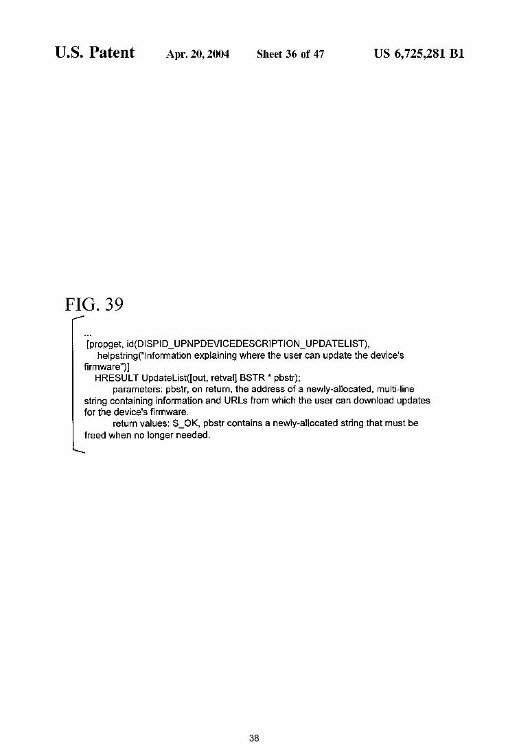
[propget, id(DISPID_UPNPDEVICEDESCRIPTION_UPDATELIST), helpstring("information explaining where the user can update the device's
firmware")] HRESULT Updatelist([out, retval] BSTR * pbstr);
parameters: pbstr, on return, the address of a newly-allocated, multi-line string containing information and URLs from which the user can download updates for the device's firmware.
return values: S_OK, pbstr contains a newly-allocated string that must be freed when no longer needed.
38
U.S. Patent Apr. 20,2004 Sheet 37 of 47
FIG. 40
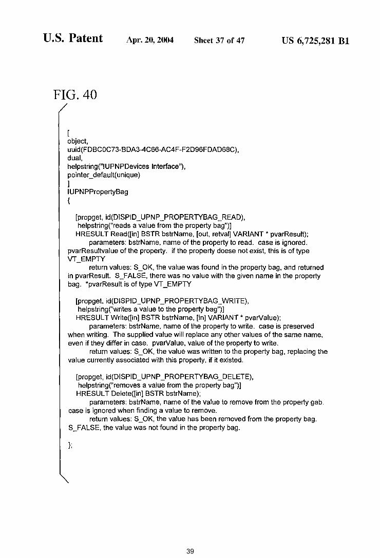
[ object, uuid(FDBCOC73-BDA3-4C66-AC4F-F2D96FDAD68C), dual, helpstring("l UPN PDevices Interface"), pointer_ default( unique) ] IUPNPPropertyBag {
[propget, id(DISPID_UPNP _PROPERTYBAG_READ), helpstring("reads a value from the property bag")]
US 6, 725,281 Bl
HRESUL T Read([in] BSTR bstrName, [out, retval] VARIANT* pvarResult); parameters: bstrName, name of the property to read. case is ignored.
pvarResultvalue of the property. if the property doese not exist, this is of type VT_EMPTY
return values: S_OK, the value was found in the property bag, and returned in pvarResult. S_FALSE, there was no value with the given name in the property bag. *pvarResult is of type VT _EMPTY
[propget, id(DISPID_UPNP _PROPERTYBAG_WRITE), helpstring("writes a value to the property bag")]
HRESUL T Write([in] BSTR bstrName, [in] VARIANT* pvarValue); parameters: bstrName, name of the property to write. case is preserved
when writing. The supplied value will replace any other values of the same name, even if they differ in case. pvarValue, value of the property to write.
return values: S_OK, the value was written to the property bag, replacing the value currently associated with this property, if it existed.
[propget, id(DISPID_UPNP _PROPERTYBAG_DELETE), helpstring("removes a value from the property bag")] HRESUL T Delete([in] BSTR bstrName);
parameters: bstrName, name of the value to remove from the property gab. case is ignored when finding a value to remove.
return values: S_OK, the value has been removed from the property bag. S_FALSE, the value was not found in the property bag.
};
39
U.S. Patent
FIG. 41
[ object,
Apr. 20, 2004 Sheet 38 of 47
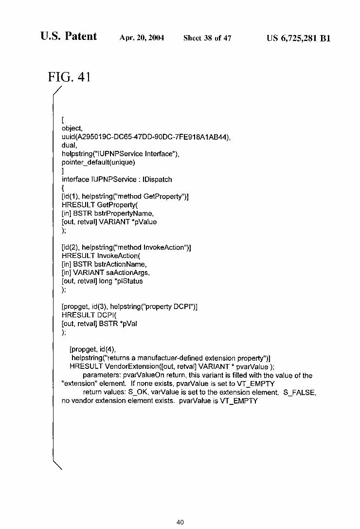
uuid(A295019C-DC65-47DD-90DC-7FE918A 1AB44), dual, helpstring("IUPNPService Interface"), pointer_default(unique) ] interface IUPNPService: !Dispatch { [id(1 ), helpstring("method GetProperty")] HRESUL T GetProperty( [in] BSTR bstrPropertyName, [out, retval] VARIANT *pValue );
[id(2}, helpstring("method lnvokeAction")] HRESUL T lnvokeAction( [in] BSTR bstrActionName, [in] VARIANT saActionArgs, [out, retval] long *piStatus );
[propget, id(3), helpstring("property DCPI")] HRESUL T DCPI( [out, retval] BSTR *pVal );
[propget, id(4),
US 6, 725,281 Bl
helpstring("returns a manufactuer-defined extension property")] HRESUL T VendorExtension([out, retval] VARIANT* pvarValue );
parameters: pvarValueOn return, this variant is filled with the value of the "extension" element. If none exists, pvarValue is set to VT _EMPTY
return values: S_OK, varValue is set to the extension element. S_FALSE, no vendor extension element exists. pvarValue is VT _EMPTY
40
U.S. Patent Apr. 20,2004 Sheet 39 of 47
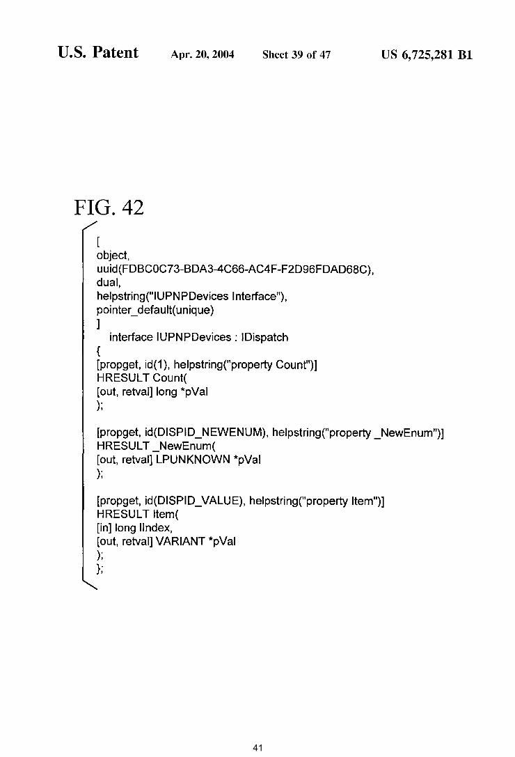
FIG. 42
[ object, uuid(FDBCOC73-BDA3-4C66-AC4F-F2D96FDAD68C), dual, helpstring("IUPNPDevices Interface"), pointer_ default( unique) ]
interface IUPNPDevices: !Dispatch { [propget, id(1 ), helpstring("property Count")] HRESUL T Count( [out, retval] long *pVal );
US 6, 725,281 Bl
[propget, id(DISPID_NEWENUM), helpstring("property _NewEnum")] HRESUL T _NewEnum( [out, retval] LPUNKNOWN *pVal );
[propget, id(DISPID_ VALUE), helpstring("property Item")] HRESUL T Item( [in] long llndex, [out, retval] VARIANT *pVal ); };
41
U.S. Patent
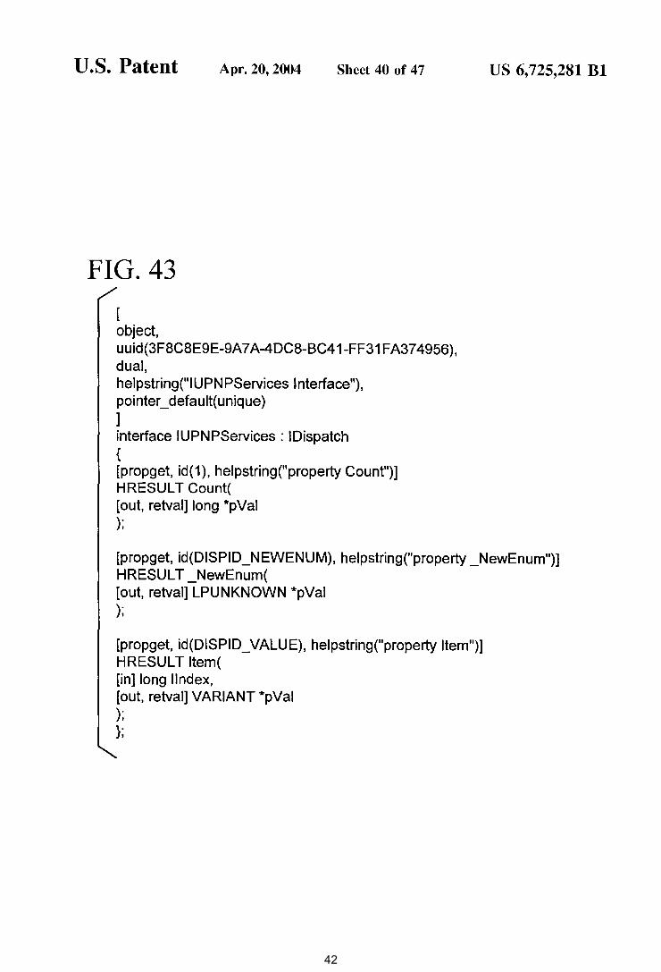
FIG. 43
[ object,
Apr. 20, 2004 Sheet 40 of 47
uuid(3F8C8E9E-9A7 A-4DC8-BC41-FF31 FA37 4956), dual, helpstring("IUPNPServices Interface"), pointer_ default(unique) ] interface IUPNPServices: !Dispatch { [propget, id(1), helpstring("property Count")] HRESUL T Count( [out, retval] long *pVal );
US 6, 725,281 Bl
[propget, id(DISPID_NEWENUM), helpstring("property _NewEnum")] HRESUL T _NewEnum( [out, retval] LPUNKNOWN *pVal );
[propget, id(DISPID_ VALUE), helpstring("property Item")] HRESULT Item( [in] long llndex, [out, retval] VARIANT *pVal ); };
42
U.S. Patent Apr. 20,2004
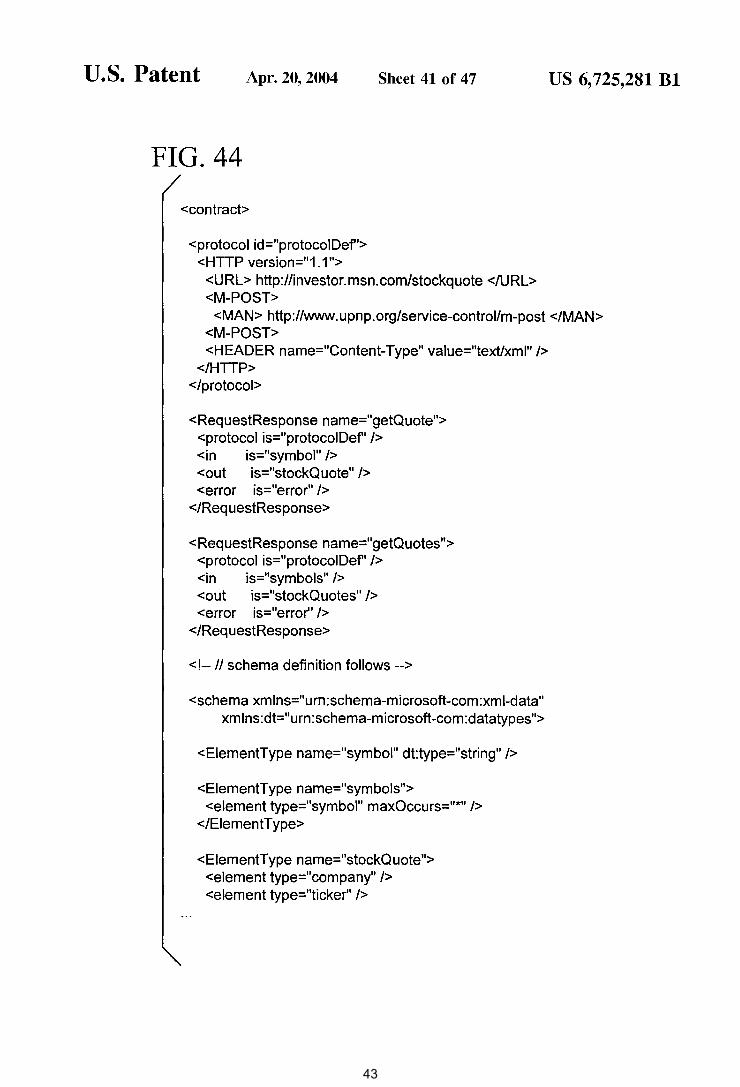
FIG. 44
<contract>
<protocol id="protocoiDef'> <HTTP version=" 1.1 ">
Sheet 41 of 47
<URL> http://investor.msn.com/stockquote </URL> <M-POST>
US 6, 725,281 Bl
<MAN> http://www. upnp. org/service-control/m-post </MAN> <M-POST> <HEADER name="Content-Type" value="text/xml" />
</HTTP> </protocol>
<RequestResponse name="getQuote"> <protocol is="protocoiDef' /> <in is="symbol" /> <out is="stockQuote" /> <error is="error" />
</RequestResponse>
<RequestResponse name="getQuotes"> <protocol is="protocoiDef' /> <in is="symbols" /> <out is="stockQuotes" /> <error is="error'' />
</RequestResponse>
< !-- II schema definition follows -->
<schema xmlns="urn:schema-microsoft-com:xml-data" xmlns:dt="urn:schema-microsoft-com:datatypes">
<EiementType name="symbol" dt:type="string" />
<EiementType name="symbols"> <element type="symbol" maxOccurs="*" />
</EiementType>
<EiementType name="stockQuote"> <element type=" company" /> <element type="ticker" />
43
U.S. Patent Apr. 20,2004 Sheet 42 of 47
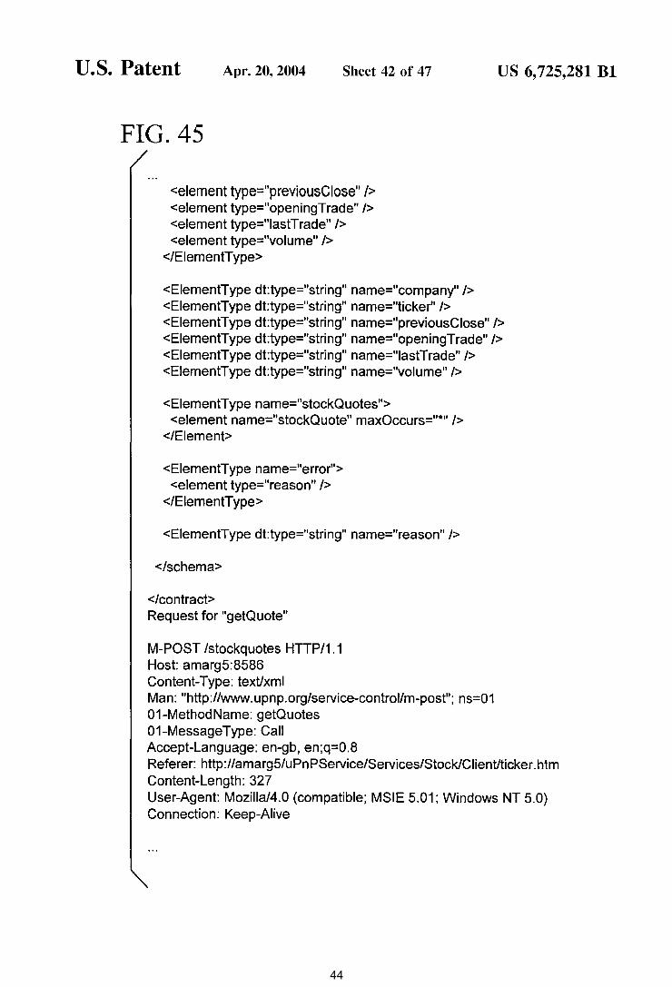
FIG. 45
<element type="previousCiose" /> <element type="openingTrade" /> <element type="lastTrade" /> <element type="volume" />
</EiementType>
US 6, 725,281 Bl
<EiementType dt:type="string" name="company" /> <EiementType dt:type="string" name="ticker" /> <EiementType dt:type="string" name="previousCiose" /> <EiementType dt:type="string" name="openingTrade" /> <EiementType dt:type="string" name="lastTrade" /> <EiementType dt:type="string" name="volume" />
<EiementType name="stockQuotes"> <element name="stockQuote" maxOccurs="*" />
</Element>
<EiementType name="error"> <element type=" reason" />
</Element Type>
<EiementType dt:type="string" name="reason" />
</schema>
</contract> Request for "getQuote"
M-POST /stockquotes HTTP/1.1 Host: amarg5:8586 Content-Type: text/xml Man: "http://www.upnp.org/service-controllm-post"; ns=01 01-MethodName: getQuotes 01-MessageType: Call Accept-Language: en-gb, en;q=0.8 Referer: http://amarg5/uPnPService/Services/Stock/Ciient/ticker.htm Content-Length: 327 User-Agent: Mozilla/4.0 (compatible; MSIE 5.01; Windows NT 5.0) Connection: Keep-Alive
44
U.S. Patent Apr. 20,2004
FIG. 46
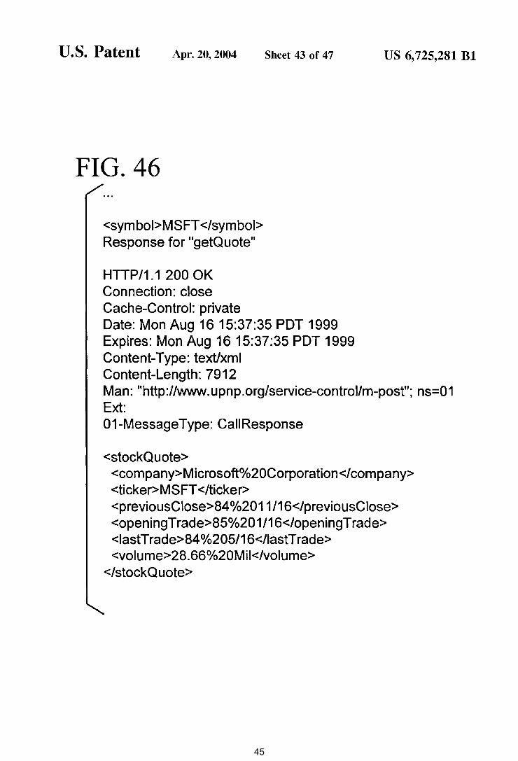
<symboi>MSFT </symbol> Response for "getQuote"
HTTP/1.1 200 OK Connection: close Cache-Control: private
Sheet 43 of 47
Date: Mon Aug 16 15:37:35 PDT 1999 Expires: Mon Aug 16 15:37:35 PDT 1999 Content-Type: text/xml Content-Length: 7912
US 6, 725,281 Bl
Man: "http://www.upnp.org/service-control/m-post"; ns=01 Ext: 01-MessageType: CaiiResponse
<stockQuote> <company>Microsoft0/o20Corporation</company> <ticker>MSFT </ticker> <previousCiose>84°/o2011/16</previousCiose> <openingTrade>85o/o201/16</openingTrade> <lastTrade>84o/o205/16</lastTrade> <volume>28.66°/o20Mil</volume>
</stockQ uote>
45
U.S. Patent Apr. 20,2004 Sheet 44 of 47
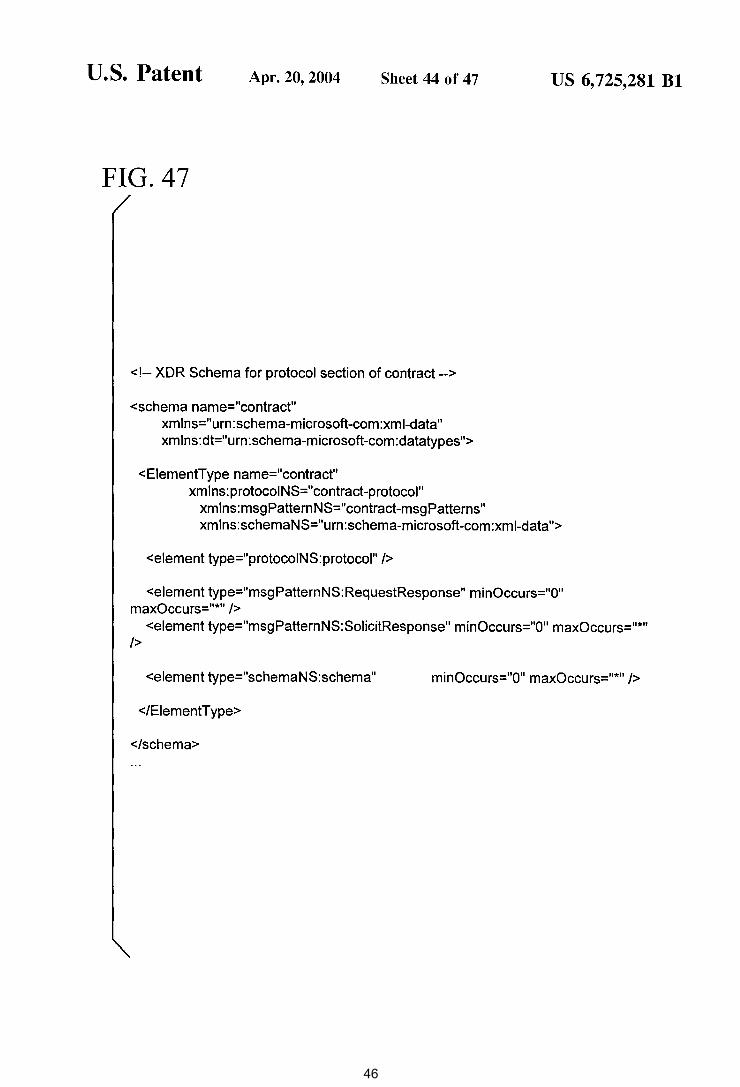
FIG. 47
<!-- XDR Schema for protocol section of contract -->
<schema name="contract" xmlns="urn:schema-microsoft-com:xml-data" xmlns:dt="urn:schema-microsoft-com:datatypes">
US 6, 725,281 Bl
<EiementType name="contract" xmlns:protocoiNS="contract-protocol"
xmlns:msgPatternNS="contract-msgPatterns" xmlns:schemaNS="urn:schema-microsoft-com:xml-data">
<element type="protocoiNS:protocol" />
<element type="msgPatternNS: RequestResponse" minOccurs="O" maxOccurs="*" />
<element type="msgPatternNS:SolicitResponse" minOccurs="O" maxOccurs="*" />
<element type="schemaNS:schema" minOccurs="O" maxOccurs="*" />
</Element Type>
</schema>
46
U.S. Patent Apr. 20,2004 Sheet 45 of 47
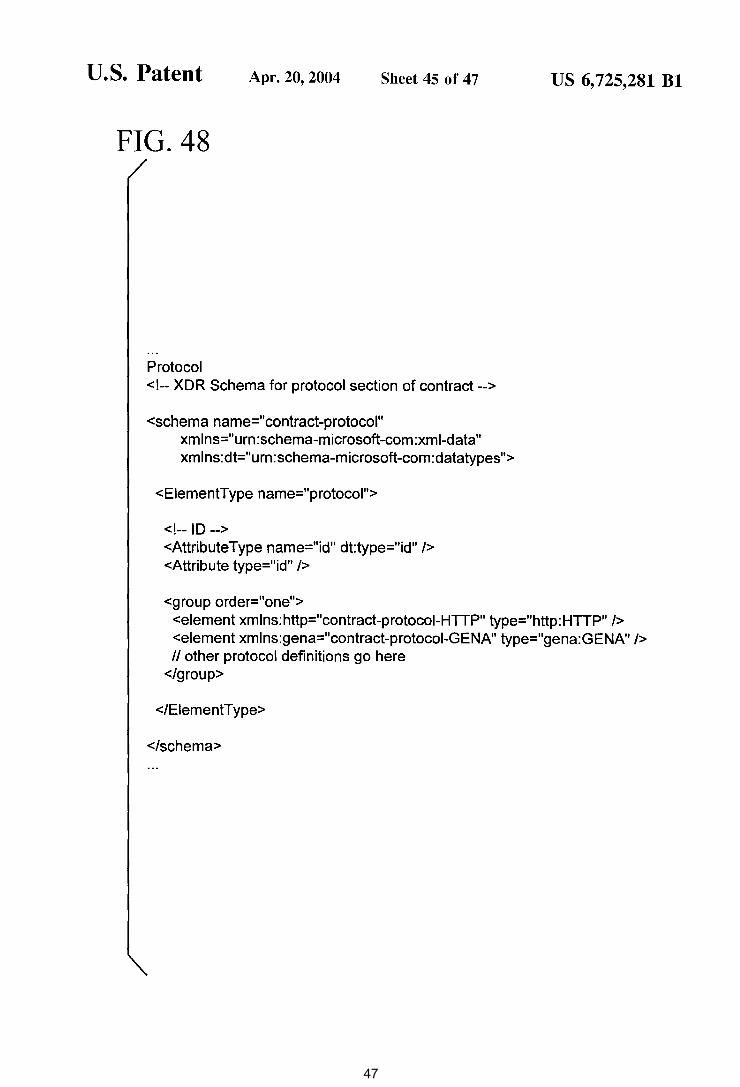
FIG. 48
Protocol <!-- XDR Schema for protocol section of contract-->
<schema name="contract-protocol" xmlns="urn:schema-microsoft-com:xml-data" xmlns:dt="urn:schema-microsoft-com:datatypes">
<EiementType name="protocol">
<!-- ID --> <AttributeType name="id" dt:type="id" /> <Attribute type="id" />
<group order="one">
US 6, 725,281 Bl
<element xmlns:http="contract-protocoi-HTTP" type="http:HTTP" /> <element xmlns:gena="contract-protocoi-GENA" type="gena:GENA" /> II other protocol definitions go here
</group>
</EiementType>
</schema>
47
U.S. Patent Apr. 20, 2004 Sheet 46 of 47
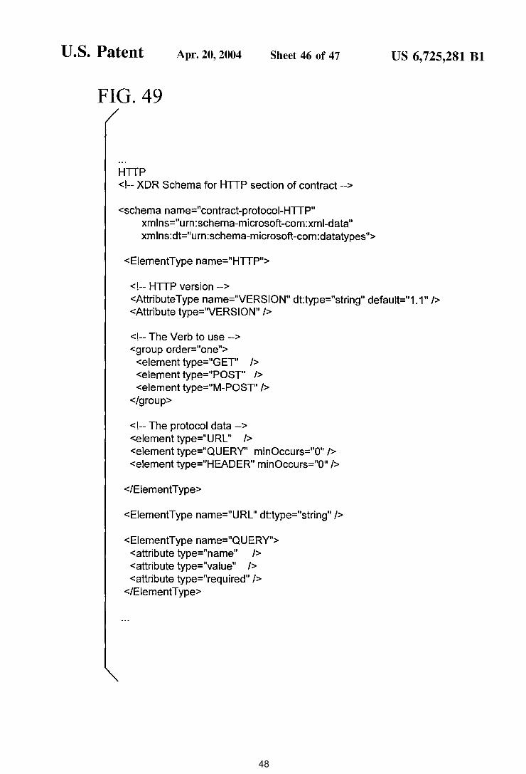
FIG. 49
HTTP <!-- XDR Schema for HTTP section of contract-->
<schema name="contract-protocoi-HTTP" xm lns="urn: schema-microsoft -com :xml-data" xmlns:dt="urn:schema-microsoft-com:datatypes">
<EiementType name="HTTP">
<!--HTTP version-->
US 6, 725,281 Bl
<AttributeType name="VERSION" dt:type="string" default="1.1" /> <Attribute type="VERSION" />
<!--The Verb to use--> <group order="one">
<element type="GET" /> <element type=" POST" /> <element type="M-POST" />
</group>
<!--The protocol data--> <element type="URL" /> <element type="QUERY" minOccurs="O" /> <element type="HEADER" minOccurs="O" />
</EiementType>
<EiementType name="URL" dt:type="string" />
<EiementType name="QUERY"> <attribute type="name" /> <attribute type="value" /> <attribute type="required" />
</EiementT ype>
48
U.S. Patent Apr. 20, 2004 Sheet 47 of 47
FIG.50
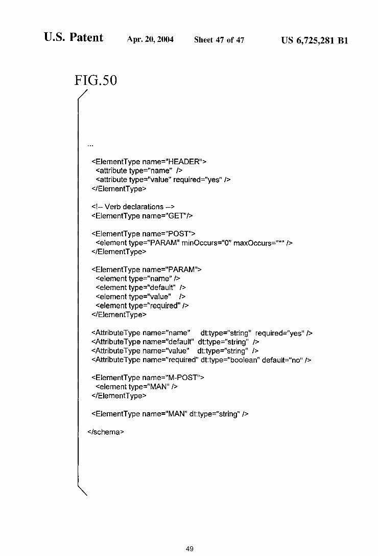
<EiementType name="HEADER"> <attribute type="name" /> <attribute type="value" required="yes" />
</EiementType>
<!--Verb declarations --> <EiementType name="GET"/>
<EiementType name="POST">
US 6, 725,281 Bl
<element type="PARAM" minOccurs="O" maxOccurs="*" /> </EiementT ype>
<EiementT ype name="PARAM"> <element type="name" /> <element type="default" /> <element type="value" /> <element type="required" />
</Element Type>
<AttributeType name="name" dt:type="string" required="yes" /> <AttributeType name="default" dt:type="string" /> <AttributeType name="value" dt:type="string" /> <Attribute Type name="required" dt:type="boolean" default="no" />
<EiementType name="M-POST"> <element type="MAN" />
</EiementType>
<EiementType name="MAN" dt:type="string" />
</schema>
49
US 6,725,281 Bl 1
SYNCHRONIZATION OF CONTROLLED DEVICE STATE USING STATE TABLE AND
EVENTING IN DATA-DRIVEN REMOTE DEVICE CONTROL MODEL
RELATED APPLICATION DATA
This application is based on provisional application No. 60/139,137 filed Jun. 11, 1999, and provisional application No. 60/160,235 filed Oct. 18, 1999.
TECHNICAL FIELD
This invention relates generally to dynamic connectivity among distributed devices and services, and more particularly relates to providing a capability to access device- or service-specific operational information and perform remote automation and control of embedded computing devices using a data-driven remote programming model, such as in a pervasive computing environment
BACKGROUND AND SUMMARY
The cost of computing and networking technologies have fallen to the point where computing and networking capabilities can be built into the design of many electronic devices in the home, the office and public places. The combination of inexpensive and reliable shared networking media with a new class of small computing devices has created an opportunity for new functionality based mainly on the connectivity among these devices. This connectivity can be used to remotely control devices, to move-digital data in the form of audio, video and still images between devices, to share information among devices and with the unconstrained World Wide Web of the Internet (hereafter "Web") and to exchange structured and secure digital data to support things like electronic commerce. The connectivity also enables many new applications for computing devices, such
2 table representative of their operational state. Devices that provide a user interface or user control point for the controlled device obtain the state table of the controlled device, and may also obtain presentation data defining presentation
5 of the remoted user interface of the controlled device and device control protocol data defining commands and data messaging to effect control of the controlled device. These user control point devices also subscribe to notifications of state table changes, which are distributed from the con-
10 trolled device according to an eventing model. Accordingly, upon any change to the controlled device's operational state caused by user inputs from any user control point device or even the controlled device's front panel or infrared remote, the device's state as represented in the state table is syn-
15 chronized across all these user control point devices using the eventing model.
The device state table and eventing model enable dynamic and automatic synchronization of the device state among all interested controllers that subscribe to notifications of the
20 controlled device's state upon a change in the controlled device's state, whether the device commands that cause a change in device state originate from other user control point devices or directly through front panel or infrared remote of the controlled device itself. This synchronization of the
25 controlled device's state among all user control point devices that provide a user interface to the controlled device allows these user control point devices to present a consistent and correct depiction of the controlled device's state in their user interface. This way the user is able to interact
30 appropriately to the actual current state of the device, e.g., avoiding issuing a "toggle power on/off'' command when the controlled device's power already is on. The controlled device thus is able to truly remote its direct front panel/ infrared remote user interface as a virtual user interface on
35 other user control point devices in a distributed network.
as proximity-based usage scenarios where devices interact based at least in part on geographical or other notions of proximity. A prevalent feature of these connectivity see-
40 narios is to provide remote access and control of connected devices and services from another device with user interface capabilities (e.g., a universal remote controller, handheld computer or digital assistant, cell phones, and the like). These developments are occurring at the same time as more
45 people are becoming connected to the Internet and as connectivity solutions are falling in price and increasing in speed. These trends are leading towards a world of ubiquitous and pervasive networked computing, where all types of devices are able to effortlessly and seamlessly interconnect
50 and interact.
The device state table also may contain entries that are a byte block or data buffer, in which a file can be loaded. In such embodiments, the device state table and eventing model enable a file transfer from the controlled device to interested subscribing devices via loading of the file into the data buffer entry of the device state table. Since the eventing model can broadcast any change to the data state table, the eventing model can effect an immediate file transfer upon any change in the file. Further, multiple files can be transferred by loading one at a time into this data buffer entry of the device state table.
Additional, features and advantages will be made apparent from the following detailed description of the illustrated embodiment which proceeds with reference to the accompanying drawings.
As just mentioned, a large number of usage scenarios in pervasive networked computing involve ad hoc remote control of operational functionality of various other devices from a device with user data input/output capabilities. For 55 example, in some usage scenarios, a device with user interface capabilities controls an exchange of data between image, video, and audio capture devices (e.g., cameras and recorders) and recording, play-back and presentation devices (e.g., a television, printer, and data storage devices). 60 In these scenarios, the user interface experience of a controlled device's physical control panel (e.g., the buttons, knobs and display of an audio/video equipment's front panel and infrared remote) are desirably remoted to other user interface capable control devices. 65
In accordance with a technology described herein, controlled devices in a device control model maintain a state
BRIEF DESCRIPTION OF THE DRAWINGS
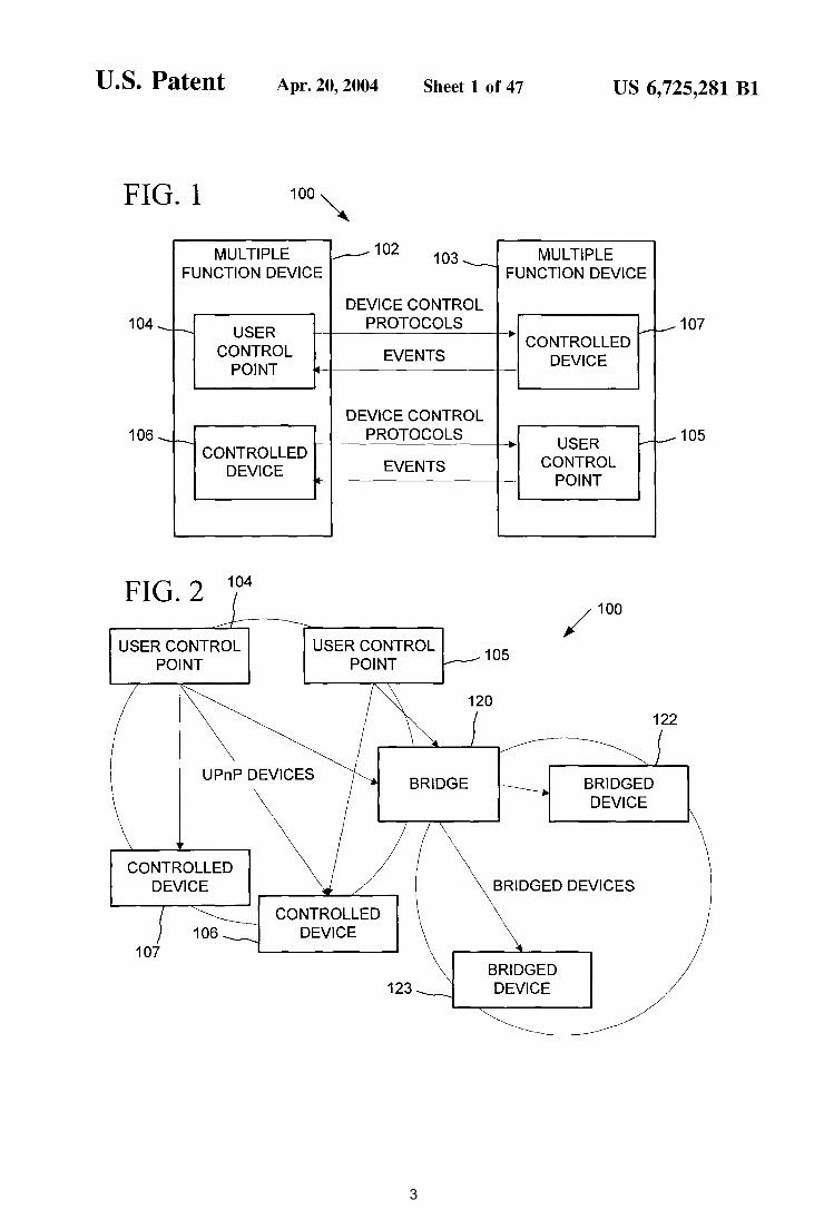
FIGS. 1 and 2 are block diagrams of a device architecture per Universal Plug and Play using user control points, controlled devices and bridges for connectivity between devices.
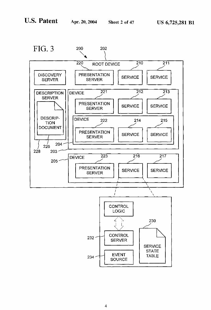
FIG. 3 is a block diagram of a device model per Universal Plug and Play.
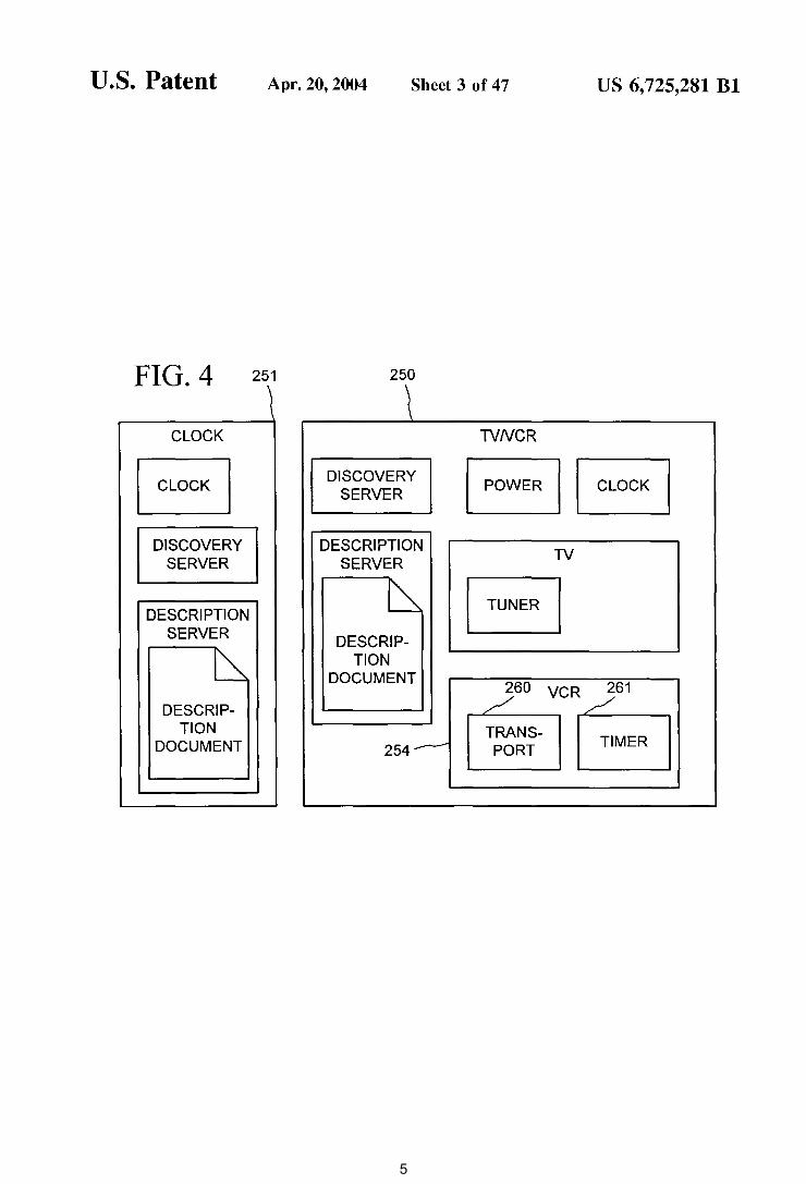
FIG. 4 is a block diagram illustrating example devices conforming to the device model of FIG. 3.
FIG. 5 is a block diagram illustrating device state synchronization using a state table and eventing.
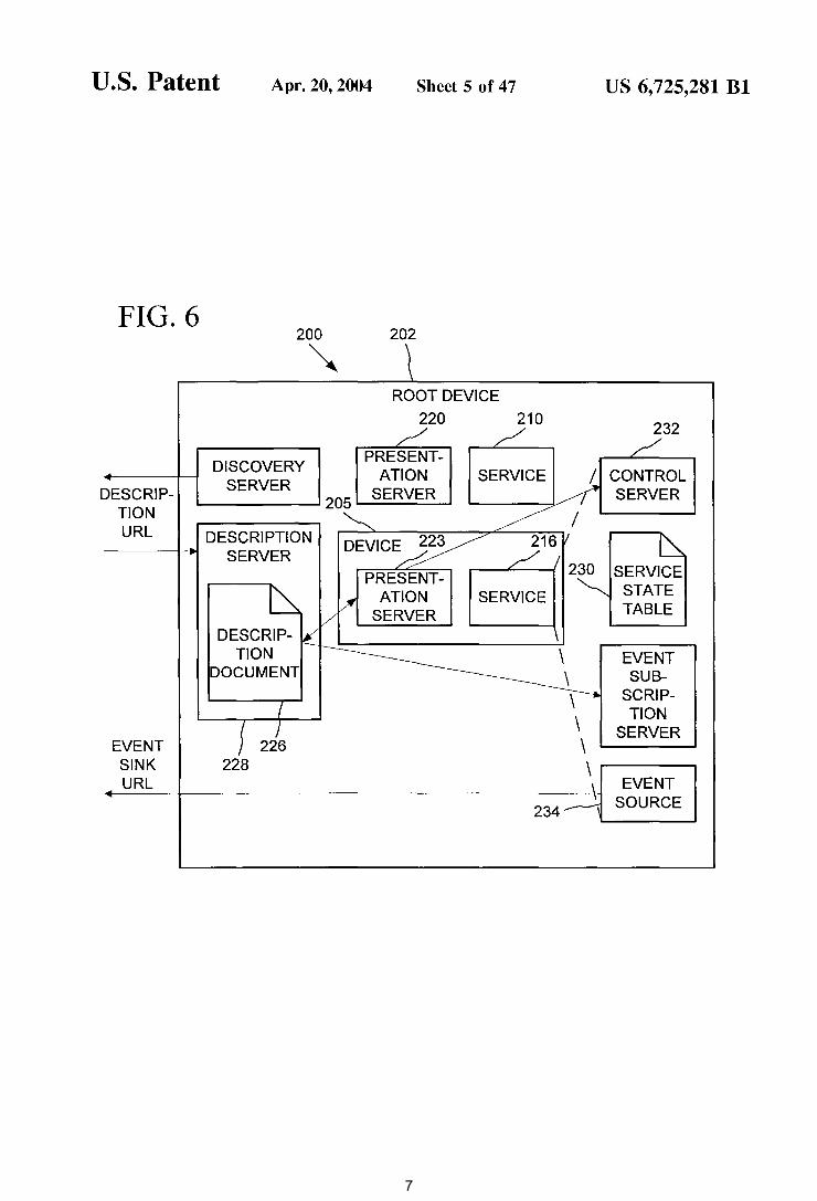
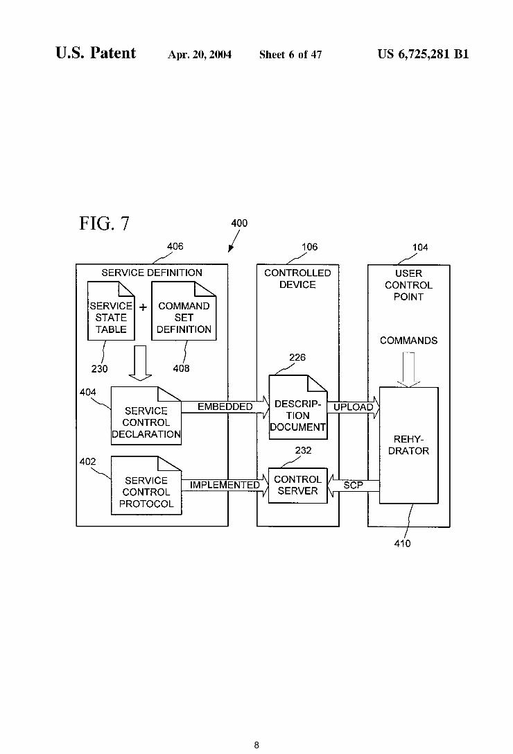
FIG. 6 is a block diagram illustrating device addressing. FIG. 7 is a block diagram of a programmatic interface
to-network messaging adapter or Rehydrator in the device control model of FIG. 3.
50
US 6,725,281 Bl 3
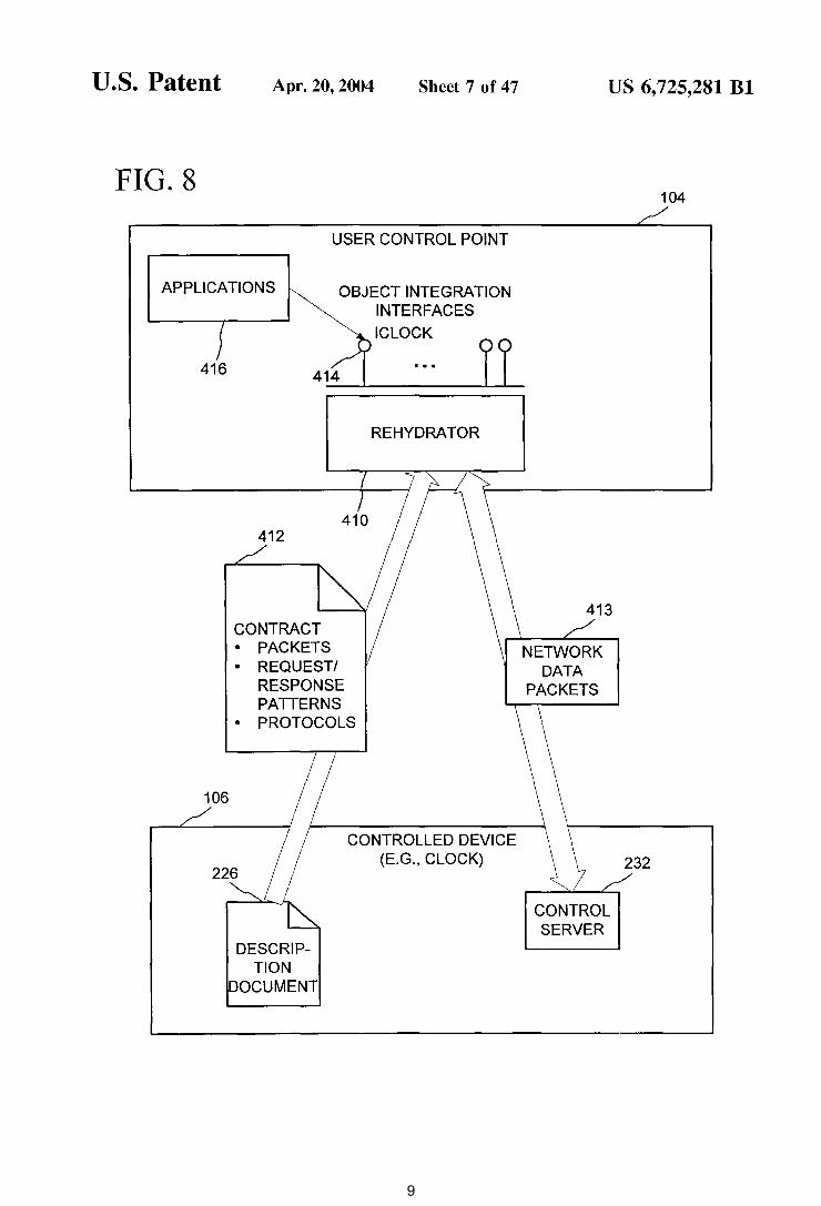
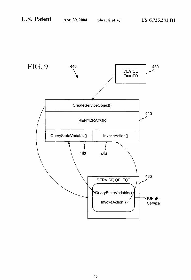
FIG. 8 is a general data flow diagram of the Rehydrator of FIG. 7 in the device control model of FIG. 3.
FIG. 9 is a block diagram of an implementation design of the Rehydrator of FIG. 7.
4 FIGS. 47-50 are an XML format listing that depicts an
XML schema for defining Contracts.
DETAILED DESCRIPTION
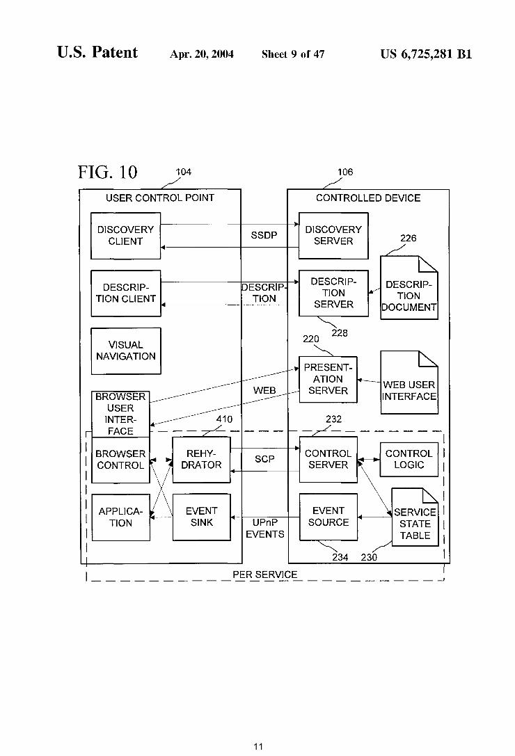
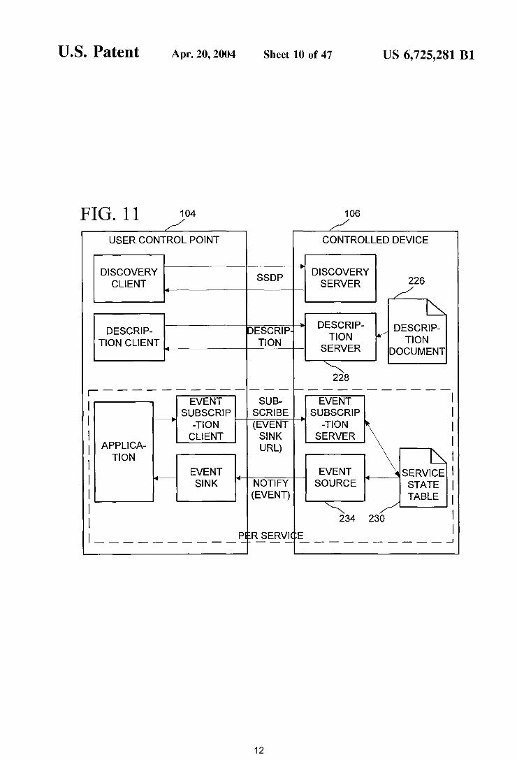
FIGS. 10 and 11 are block diagrams illustrating an inter- 5
nal software architecture of the user control point and controlled device in the device control model of FIG. 3.
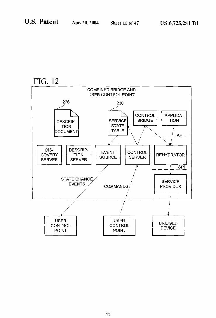
The following detailed description is directed toward a device state representation and device state eventing in a distributed device control model. In one described implementation, this device state and eventing is used in a device architecture 100 (FIG. 1), connectivity model, and FIG. 12 is a block diagram illustrating an internal soft
ware architecture of a combined bridge and user control point in the device control model of FIG. 3.
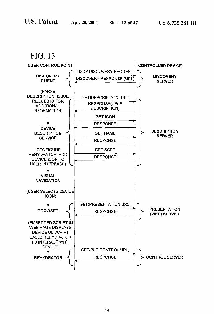
FIG. 13 is a data flow diagram illustrating a typical browsing protocol sequence in the device control model of FIG. 3.
10 device control protocol proposed by Microsoft Corporation, called Universal Plug and Play ("UPnP"). Universal Plug and Play
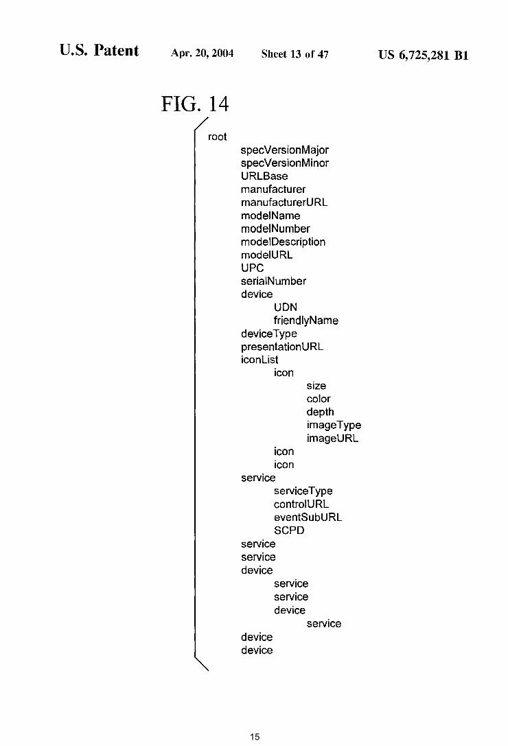
FIG. 14 is a listing showing a layout of a description 15
document in the device control model of FIG. 3.
Universal Plug and Play (UPnP) is an open network architecture that is designed to enable simple, ad hoc communication among distributed devices and services from many vendors. UPnP leverages Internet technology and can
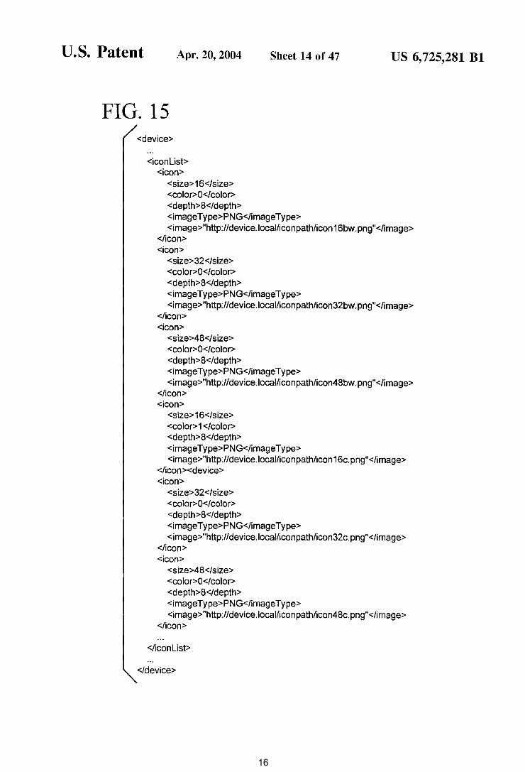
FIG. 15 is a listing of an exemplary icon list of a Description Document in the device control model of FIG. 3.
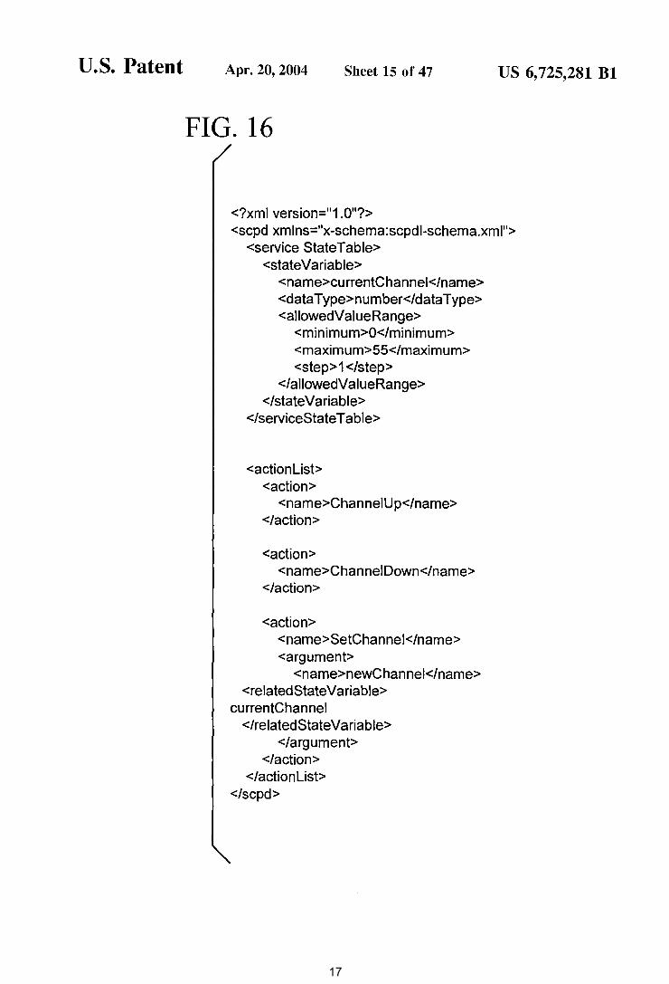
FIG. 16 is a listing of an exemplary service control 20
protocol declaration in a Description Document in the device control model of FIG. 3.
be thought of as an extension of the Web model of mobile web browsers talking to fixed web servers to the world of peer-to-peer connectivity among mobile and fixed devices. UPnP embraces the zero configuration mantra of Plug and Play (PnP) but is not a simple extension of the PnP host/ peripheral model.
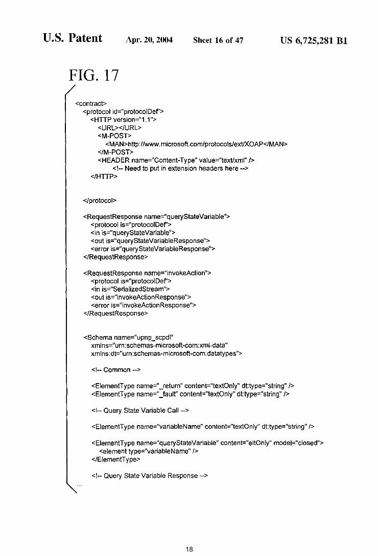
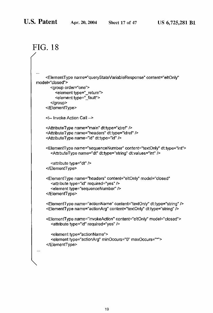
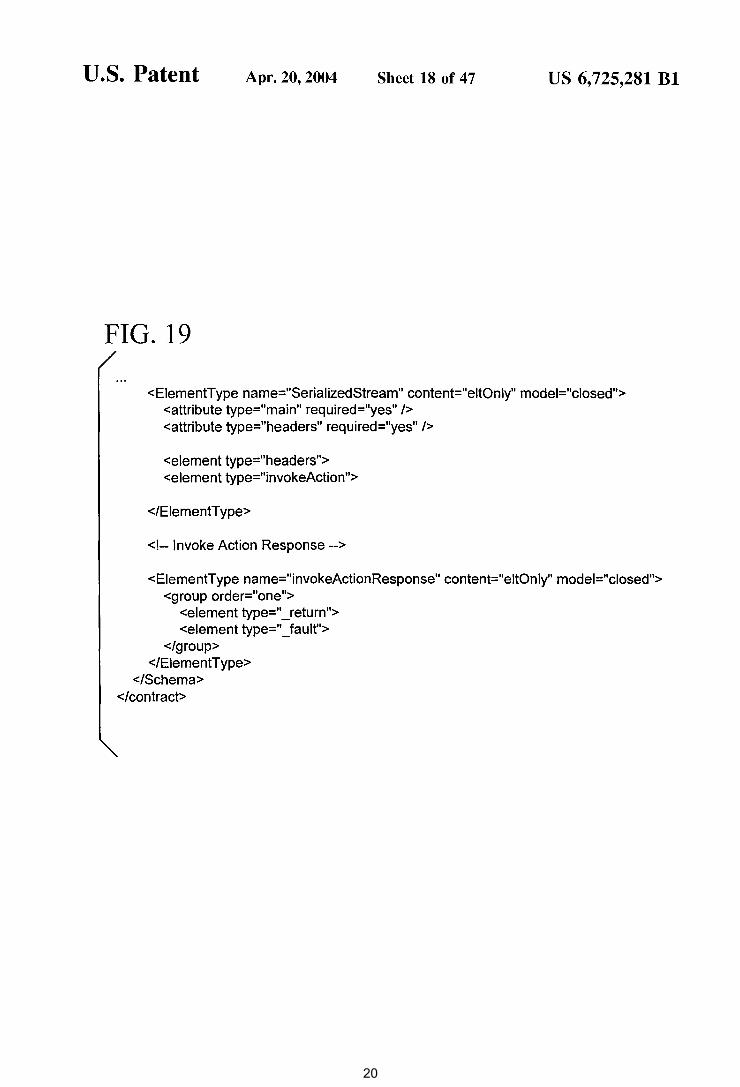
The cost, size and battery consumption of computing technology-including processing, storage and displays-FIGS.17, 18, and 19 are a listing of an exemplary contract
in the device control model of FIG. 3.
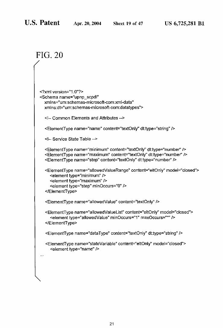
FIGS. 20 and 21 are a listing of an XML schema for a Service Control Protocol Declaration Language used in the device control model of FIG. 3.
FIG. 22 is a block diagram of an eventing model used in the device control model of FIG. 3.
FIG. 23 is a data flow diagram illustrating subscription, notification and unsubscription in the eventing model of FIG. 22.
25 continues to fall. This trend is enabling the evolution of stand-alone, single or limited function computing devices such as digital cameras, audio playback devices, smart mobile phones and handheld computers. Concurrent with this, the economical storage and transmission of digital
30 audio, video and still images is enabling highly flexible models for managing entertainment content.
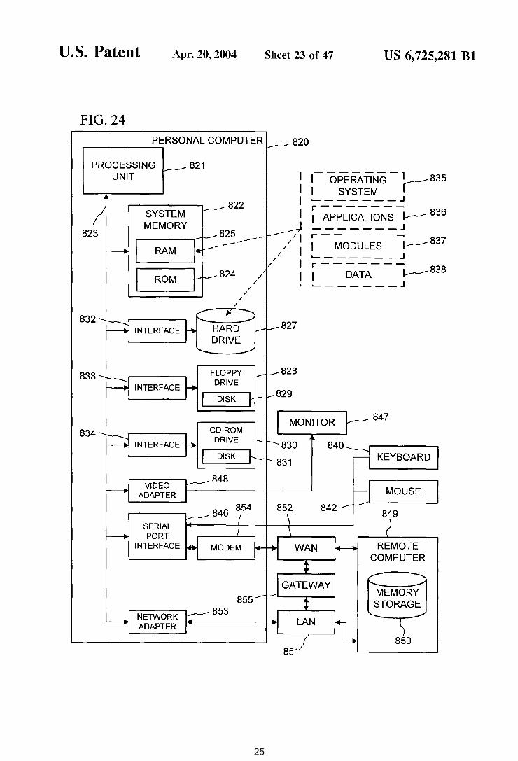
FIG. 24 is a block diagram of a computer system that may be used in the device control model of FIG. 3. 35
While many of these devices are capable of useful standalone operation, seamless connectivity with the PC can enhance the value to the customer of both stand-alone devices and the PC. Good examples of this synergy are digital image capture combined with PC image manipulation, storage and email transfer/web publishing and FIG. 25 is a block diagram of a device having embedded
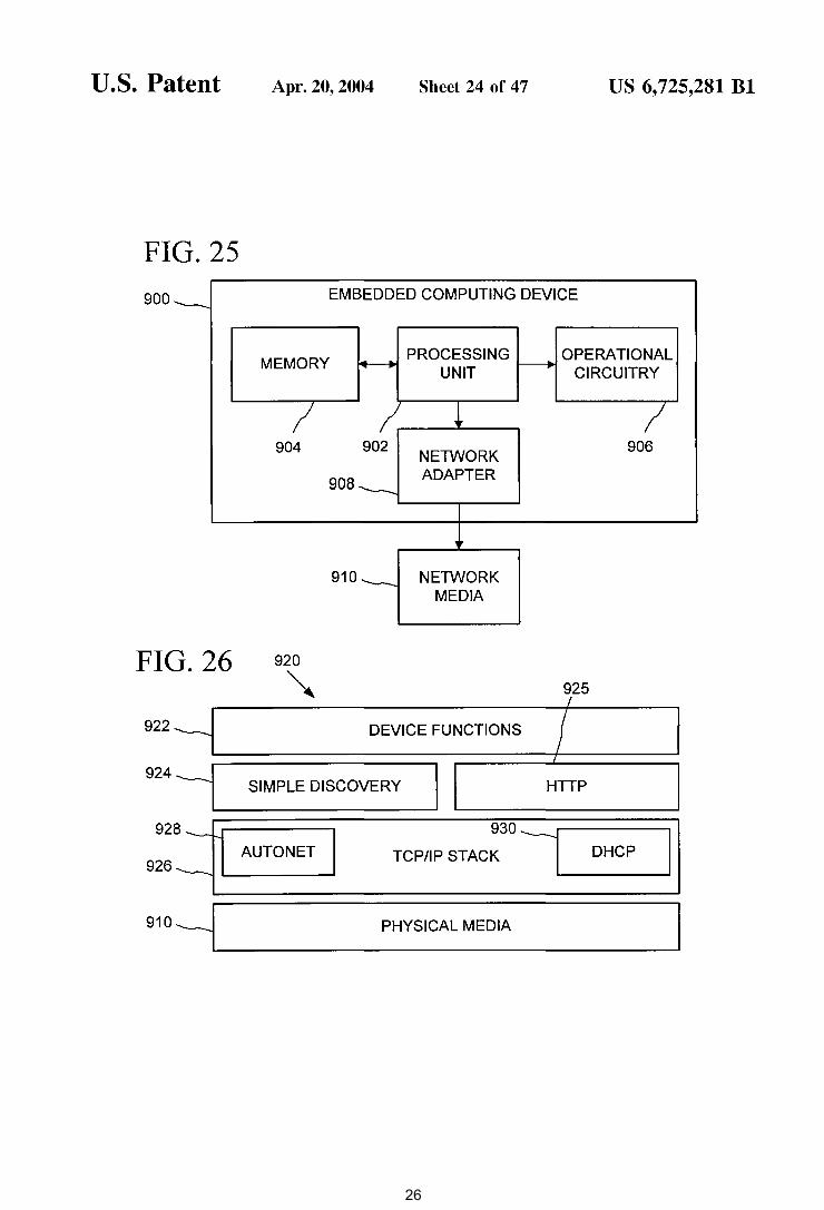
computing and networking capability per universal-plugand-play (UPNP) standards that may be used in combination with the computer system of FIG. 24 in the device control
40 model of FIG. 3.
information synchronization between a PC and a handheld computer or smart mobile phone.
Since many of these devices, and the PC itself, are mobile, a suitable communication architecture must enable a highly dynamic connectivity model and must enable peer-to-peer operating among arbitrary combinations of devices.
FIG. 26 is a block diagram of a software architecture per UPNP standards in the embedded computing device of FIG. 25
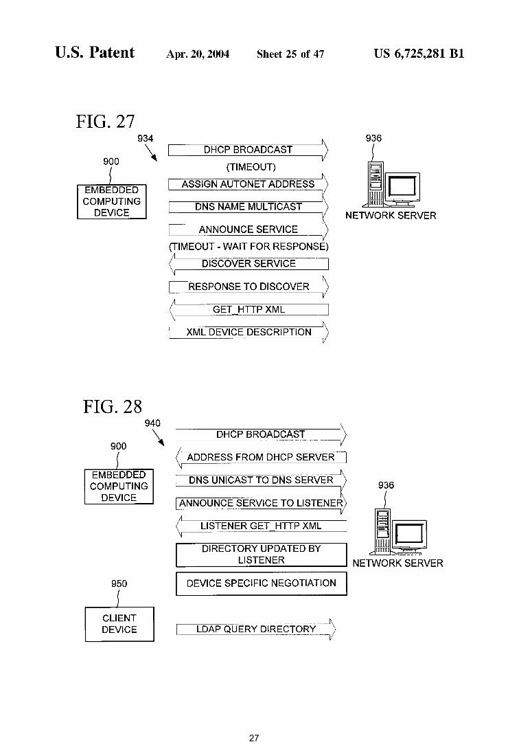
FIG. 27 is a data flow diagram of a process for automatic network introduction of the embedded computing device of FIG. 25 into an ad hoc computer network environment per the UPNP protocol.
FIG. 28 is a data flow diagram of a process for automatic network introduction of the embedded computing device of FIG. 25 into a configured computer network environment per the UPNP protocol.
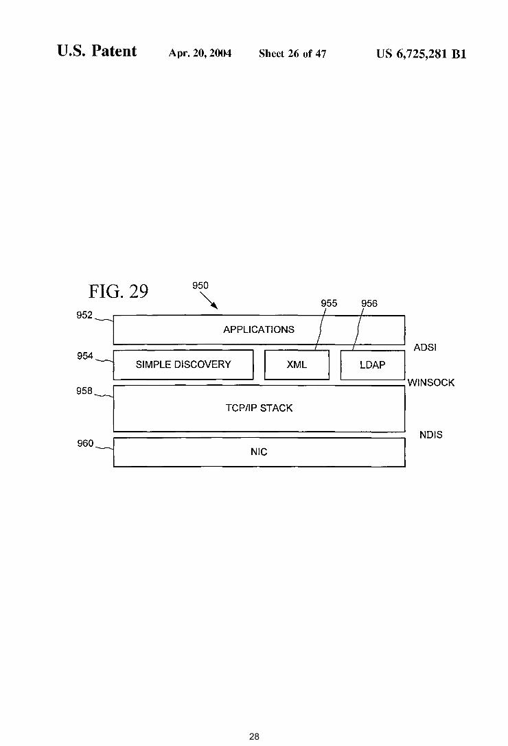
FIG. 29 is a block diagram of a software architecture of
The Internet has created a widespread awareness of the 45 value of simple, universal communication that is indepen
dent of the underlying transmission technology and independent of technology from any single vendor.
UPnP makes it possible to initiate and control the transfer of bulk data (e.g. files) or NV data streams from any device
50 on the network, to any device on the network, under the control of any device on the network. UPnP enables the ad hoc addition or removal of devices on the network, and it enables multiple controlling devices to remain in sync with each other. a client device per UPNP standards having embedded com
puting and networking capability that may be used in the 55
device control model of FIG. 3.
UPnP reuses existing protocols and technology whenever possible. The transition to this highly connected (and connectable) world will not occur overnight. UPnP builds on existing Internet protocols, but accommodates devices that cannot run the complete UPnP protocol suite. UPnP provides
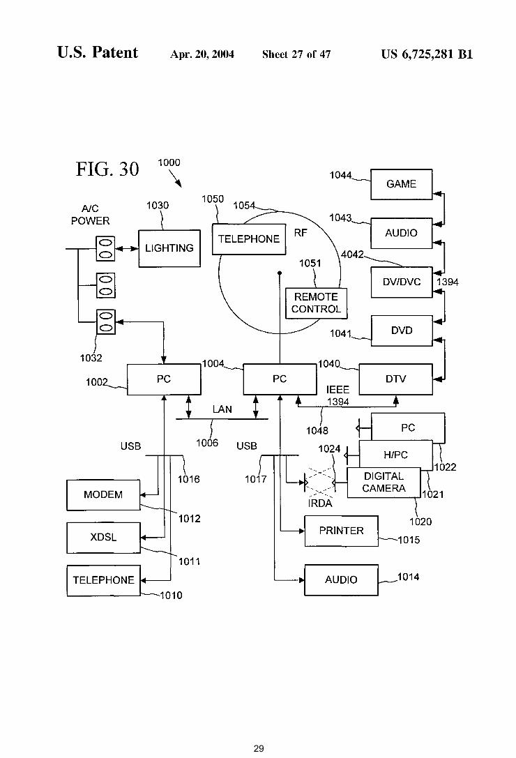
FIG. 30 is a block diagram of an exemplary home or office pervasive computing environment having a variety of computers as per FIG. 24 and embedded computing devices as per FIG. 25 interconnected per UPNP standards that may be used in the device control model of FIG. 3.
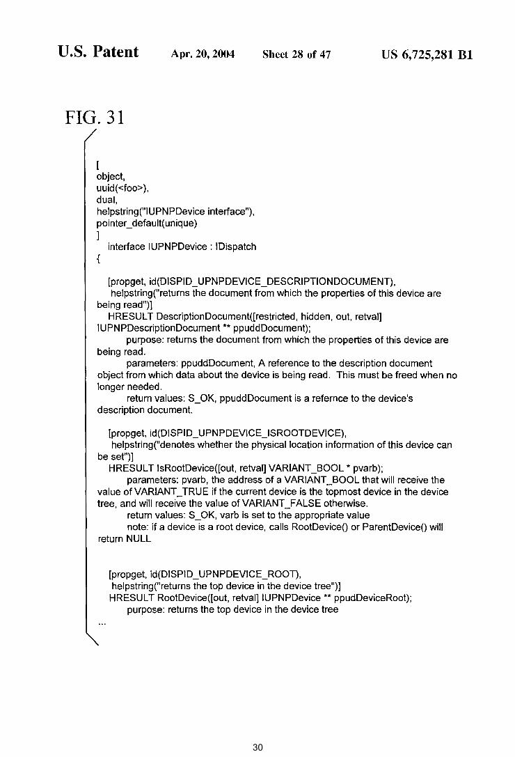
FIGS. 31 through 43 are program listings of interfaces used in the Rehydrator implementation design of FIG. 9.
FIGS. 44-46 are an XML format listing that depicts an exemplary contract for interacting with a stock quote Service.
60 an architecture that enables legacy devices to communicate with UPnP devices.
IP internetworking has been chosen as a UPnP baseline due to its proven ability to span different physical media, to enable real world multiple vendor interoperation and to
65 achieve synergy with the Internet and home and office intranets. Internet synergy enables applications such as IP telephony, multiple player games, remote control of home
51
US 6,725,281 Bl 5 6
convenient to have to a web for each light switch in a house. To support a rich user interface and to enable the aggregation of devices into a single UI, UPnP enables application control in addition to browser control of devices. This is achieved
automation and security, Internet based electronic commerce, in addition to simple email and web browsing. UPnP's scope includes remote control of devices and bulk data transfer. But, it does not specify NV streaming formats or protocols. 5 simply by enabling applications to call the same Rehydrator
APis that the browser does. Applications can also directly generate and consume the raw UPnP control protocols, provided they are not interested in the device-driven auto-
UPnP's media independence enables a great deal of flexibility in the packaging of products. UPnP enables an NV system to be controlled through an NC power communications technology, while the transmission of NV streams among the components is analog or digital. One of
10 the controllers of this system could be on the television, while another is on a PC, and yet another connected via radio or infrared.
Unlike Plug and Play, Universal Plug and Play is built on top of networking and enables ad hoc peer-to-peer connectivity. Networking, in this context, describes a style of 15
connectivity that enables any networked device to initiate a communication with any other networked device, without having established a prior relationship or maintaining a persistent relationship between the devices. Networking also allows multiple devices to establish one or more connections 20
with a single device, and it allows for a device to be capable
configuration enabled by the Rehydrator. UPnP assumes that there will be more than one device
with UI that wants to control other devices in any given network, and it provides a simple mechanism that enables these control points to remain in sync. This mechanism can easily support device front panels and wireless remotes that do not run UPnP protocols. The UPnP control model is third-party control; any device can transfer bulk data (e.g. files) or NV data streams from any device on the network, to any device on the network, under the control of any device on the network. Terminology
The detailed description that follows uses the terminology defined below.
Module. A component of a device, software program, or system that implements some "functionality", which can be embodied as software, hardware, firmware, electronic
25 circuitry, or etc.
of both initiating and accepting connections to/from other devices. The PnP, or host/peripheral, model is suitable whenever there is a natural persistent relationship between two devices (e.g. a keyboard, mouse and display maintain and a persistent relationship with a host computer). Even though networking does not mandate low level persistent relationships, it provides the needed anchors (addresses) for applications to choose to maintain associations as a convenience for the customer (e.g. remembering commonly used 30
networked printers).
User Control Point. The set of modules that enable communication with a UPnP Controlled Device. User Control Points initiate discovery and communication with Controlled Devices, and receive Events from Controlled Devices. User Control Points are typically implemented on devices that have a user interface this user interface is used to interact with Controlled Devices over the network. The modules minimally include a Discovery Client, a Description Client and a Rehydrator. User Control Points may also
In order to achieve multiple vendor peer-to-peer interoperation among devices, vendors desirably agree on common technology and standards up to the highest level of desired functional interoperation.
UPnP leverages formal protocol contracts to enable peerto-peer interoperation. Protocols contracts enable real-world multiple-vendor interoperation.
35 include Visual Navigation, an Event Subscription Client, Event Sink, a web browser and an application execution environment. User Control Points can add value to the network by aggregating the control of multiple Controlled
UPnP enables devices to expose a user interface by leveraging browser technology. In this context, the browser 40
can be considered to be a very rich remote terminal. Current browser technology does not maintain a separation of presentation from data, or in the case of devices, control. It is possible to hunt through a page of HTML to extract data values, but it is not convenient or robust. UPnP leverages the 45
separation of presentation and data enabled by the use of XML, and it extends this technology to the device control domain.
UPnP provides a device-driven auto-configuration capability that preserves the experience that customers have on 50
the web. Today, it is possible to navigate around the web without loading programs beyond the browser itself. Since UPnP enables the browser to be extended to control devices, and because UPnP devices are controlled with explicit protocols, the browser must somehow learn how to talk to 55
UPnP devices. This learning process is driven entirely from the device itself and is accomplishing entirely by uploading an XML document that describes the capabilities of the device. The architectural component that enables devicedriven auto-configuration is called the Rehydrator. The job 60
of the Rehydrator is to convert between APis and protocols. Since the auto-configuration process itself is driven only
Devices (the universal remote) or they can implement a function as simple as initiating the transfer of data to or from a Controlled Device. Examples of devices that could be User Control Points are the personal computer (PC), digital television (DTV), set-top box (STB), handheld computer and smart mobile phone, and the like. Nothing prevents a single device from implementing the functionality of a User Control Point and one or more Controlled Devices at the same time.
Controlled Device. The set of modules that enable communication with a User Control Point. Controlled Devices respond to discovery requests, accept incoming communications from User Control Points and may send Events to User Control Points. Devices that support Controlled Device functionality may also support local user interfaces such as front panel displays or wireless remotes. The modules minimally include a Discovery Server, a Description Server and a Control Server. Controlled Devices may also include a Presentation (web) Server, Event Subscription Server and Event Source. Examples of devices that could be Controlled Devices are the VCR, DVD player or recorder, heating/ ventilation/air-conditioning equipment (HVAC), lighting controller, audio/video/imaging playback device, handheld computer, smart mobile phone and the PC, and the like. Nothing prevents a single device from implementing the functionality of a User Control Point and one or more
by the exchange of formatted data, there is very little opportunity for a malicious attack from a hostile piece of code. 65 Controlled Devices at the same time.
There are some scenarios where the web UI model is not sufficient for a rich customer experience. It would not be
Bridge. A set of modules that enables Bridged and Legacy Devices to interact with native UPnP devices. The bridge
52
US 6,725,281 Bl 7 8
(URI): Generic Syntax", which can be found at http://www.ietf.org/rfc/rfc2396.txt.
Device Friendly Name. A human readable string that is initialized by vendors at the time of manufacturer of a
itself exposes a collection of UPnP Controlled Devices to User Control Points. The Bridge maps between native UPnP Device Control Protocols and the underlying protocols exposed by the Bridged and Legacy Devices. Optionally, such a device could expose UPnP Controlled Devices to Legacy Devices in the manner required by the Legacy Devices. Nothing prevents a single device from implementing the functionality of a User Control Point, one or more Controlled Devices and a Bridge at the same time.
5 Device. Every Device, including Root Devices, has a Device Friendly Name. A typical Device Friendly Name will contain manufacturer and model information, and is used to enable a more precise identification of a UPnP Device from the set of discovered Devices. Once identified, the Unique
Service Provider. A module used by a UPnP Bridge that translates between UPnP protocols and the protocols used by Bridged and Legacy Devices. No Service Providers are required for communication among native UPnP devices.
Bridged Device. A device that cannot participate in UPnP
10 Device Name (UDN) can be used to unambiguously identify the same Device in the future. UPnP enables Device Friendly Names to be changed by User Control Points. The Device Friendly Name should not be used as device identifier.
Unique Device Name (UDN). The fundamental identifier of a Device. Every Device, including Root Devices, has exactly one UDN. The UDN is globally unique and permanent, even across power cycles and physical location changes. The UDN is the only UPnP device identifier
at the native protocol level, either because the device does 15
not have sufficient resources or because the underlying media is unsuitable to run TCP and HTTP. Examples of devices that could be Bridged Devices are power linecontrolledAN equipment, light switches, thermostats, wristwatches and inexpensive toys. Bridged Devices are UPnP complaint and are exposed to other UPnP devices through a UPnP Bridge.
20 guaranteed never to change. UPnP enables searches for devices by UDN.
Description Document. A structured unit of data that is used by a User Control Point or UPnP Bridge to learn the capabilities of a Controlled Device. Description Documents
Legacy Device. Any non-UPnP compliant device that must be exposed to other UPnP devices through a UPnP Bridge.
Device Model. The UPnP model of Controlled Devices. The Device Model includes the addressing scheme, Description Document, Devices and Services hierarchy and the functional description of modules.
25 are retrieved from the Description Server on a UPnP Controlled Device. There is one Description Document for every Root Device that describes the Root Device and all nonRoot Devices. Description Documents adhere to XML
Device Control Protocol (DCP). A complete set of UPnP 30
protocols and schemas used to interact with a UPnP Controlled Device.
grammar. To support localization, multiple Description Documents can exist. A User Control Point requests the preferred localized Description Document by using the standard HTTP "accept-language" header.
Service. The fundamental UPnP controllable entity (but not the finest level of control). An example of a Service is
Device Definition. The formal definition of a Device Type. A Device Definition includes a Device Type Identifier, the fixed elements in the Description Document, the required set of Service Definitions in the Root Device, and the hierarchy of required Devices and Service Definitions.
Service Definition. The formal definition of a Service Type. A Service Definition includes a Service Type Identifier, definition of the Service State Table (SST), definition of the Service Command Set, the Service Control Protocol (SCP) and Service Control Protocol Declaration (SCPD).
35 "Clock". Services are defined with a mandatory common base set of functionality. Vendors can extend the base set with proprietary extensions provided the base functionality is implemented. Service Definitions are versioned and later versions are constrained to be supersets of previous ver-
40 sions. UPnP enables searches for all Devices that contain a
Device. In the context of the Device Model, a container for Services. A Device generally models a physical entity 45
such as a VCR, but can also represent a logical entity. A PC emulating the traditional functions of a VCR would be an example of a logical device. Devices can contain other Devices. An example would be a TV NCR packaged into a single physical unit. UPnP enables the association of user 50
interface (display icon and root web page) with every Device, including Root Device.
specified Service of a minimum version. This search would find all clocks, regardless of their packaging. A search for Device Type "Clock" would be used to find only stand-alone clocks.
Service Type. A classification of Services by their function.
Service Type Identifier. A unique identifier that identifies a Service Definition. This identifier adheres to the format of a Uniform Resource Identifier (URI). See, T. Berners-Lee, R. Fielding, L. Masinter, "Uniform Resource Identifiers (URI): Generic Syntax", which can be found at http://www.ietf.org/rfc/rfc2396.txt.
Service State Table (SST). A logical table consisting of rows of [Variable, Type, Legal Values, Default Value, Cur-
Root Device. The topmost Device in a hierarchy of nested Devices. A Device with no nested Devices is always a Root Device. 55 rent Value] that represents the current electrical, mechanical
and/or logical state of a Service. SST instances are stored on the Controlled Device itself and are the ultimate authority of the state of the Service. All local user interface, such as front
Device Type. A relatively high level classification of Devices with common functionality. Device Type is intended to enable Devices to be simply and automatically grouped for presentation. An example of a Device Type is "VCR". Device Types are formally defined in terms of a 60
required set of Service Definitions of minimum version that a compliant Device must support. UPnP supports searches for all Devices of a specified Device Type.
Device Type Identifier. A unique identifier that identifies a Device Definition. This identifier adheres to the format of 65
a Uniform Resource Identifier (URI). See, T. Berners-Lee, R. Fielding, L. Masinter, "Uniform Resource Identifiers
panels or wireless remotes are required to update the SST on UPnP compliant devices.
SST Definition: Service Command Set. A set of Commands that can be
invoked on a Service. Commands generally result in changes in the Current Value field of one or more rows of a SST. Commands are logically represented in the format Command (Variable=New Value, Variable=New Value, ... ). Services must accept or reject the complete set of changes
53
US 6,725,281 Bl 9
to a SST. There is a mandatory standard Query Command that is used to retrieve the Current Value of any row of a SST.
Service Command Set Definition: Service Control Protocol (SCP). The protocol used to
invoke Commands against a Service and to return results. There is exactly one SCP per Service Definition. SCPs adhere to the grammar of SCP XML schema. SCPs can be generated by an automated tool that accepts a SST Definition and a Command Set Definition as input.
Service Control Protocol Declaration (SCPD). A formal representation of the schema of a Service. The SCPD declares the rows of a Service's SST and the associated Command Set. SCPDs are uploaded from Controlling Devices in their Description Documents and enable User Control Points or Bridges to invoke Commands on the Service without any prior or persistent knowledge of the capabilities (or schema) of the Service. There is exactly one SCPD per Service Definition. SCPDs adhere to XML grammar. SCPDs can be generated by an automated tool that accepts a SST Definition and a Command Set Definition as input.
Event. An unsolicited message generated by a Controlled Device and delivered to one or more User Control Points.
10 trol Points always discover and initiate communication with Controlled Devices, but this communication requires Client and Server functionality on both sides.
Hostname. A Hostname is the Domain Name System 5 (DNS) or NetBIOS Name Service (NBNS) that, when
resolved to an IP address, represents a network interface that can be used to establish TCP/IP level connectivity to User Control Points, Controlled Devices or Bridges. Hostnames can be used to provide persistent network level addressing
10 on a network where IP addresses are dynamically assigned and of unknown lifespan or to integrate with an existing managed network. UPnP provides an algorithm for seeding a device's hostname from its UDN at manufacturing time.
Uniform Resource Locator (URL). A format for expressing web addresses. URLs minimally contain an identifica-
15 tion of the protocol family that the URL is valid for, a Hostname, and a path. UPnP uses URLs as addresses whenever the module accepting the incoming connection is an HTTP server.
Description URL. The URL returned from a Controlled 20 Device or Bridge in response to any UPnP SSDP query. This
URL always points to a Description Server on the Controlled Device. An HTTP GET can be issued on this URL to retrieve the Description Document. This URL is valid as an address for the lifetime of the Hostname embedded in the URL. Events are used to maintain a consistent view of the state of
Service across all interested User Control Points. UPnP 25 Discovery Server. The module that runs in a Controlled Device or Bridge that responds to SSDP queries. This Server is unique in that it must support UDP/HTTP rather than just TCP/HTTP.
leverages the GENA event architecture (see "Generic Event Notification") to transport event messages. All events are delivered using TCP /IP for reliability.
Generic Event Notification (GENA). An event transport protocol. GENA leverages TCP/HTTP as a transport. GENA has been submitted as an Internet Draft to the IETF. See, J. Cohen, S. Aggarwal, Y. Go land, "General Event Notification Architecture Base: Client to Arbiter", which can be found at http://www.ietf.org/internet-drafts/draft-cohen-gena-clientOO.txt.
Discovery Client. The module that runs in a User Control 30 Point that initiates SSDP queries.
Description Server. The module that runs in a Controlled Device or Bridge that responds to HTTP GETs and returns Description Documents. This service consists of a TCP/ HTTP server than can retrieve and return a Description
35 Document from persistent storage (like a filesystem). Visual Navigation. User Control Point functionality that
displays the icons of discovered Devices and enables the transfer of control to a browser or application to interact with the Controlled Device. In Windows, Visual Navigation
Simple Service Discovery Protocol (SSDP). A simple network device discovery protocol. UPnP uses SSDP to allow User Control Points to find Controlled Devices and Services. SSDP operates in a default, completely automatic multicast UDP/IP based mode in addition to a server-based mode that uses TCP/IP for registrations and query. Transitions between the default dynamic mode and server-based mode are automatic and transparent. SSDP enables every Controlled Device to control the lifetime that its Description URL is cached in all User Control Points. This enables a Controlled Device to remain visible to User Control Points for a relatively long time (through power cycles), in addition
40 could be implemented as a folder of icons. Presentation URL. A URL that can be used by a User
Control Point to navigate to the Presentation Server of a Controlled Device. This URL is returned in the Description Document and is valid as an address for the lifetime of the
45 Hostname embedded in the URL. All Devices, including non-Root Devices, can have an associated Presentation URL.
to enabling a Controlled Device to appear and disappear very quickly, all under the control of the Controlled Device. SSDP and related Multicast and Unicast UDP HTTP Mes- 50
sages specifications have been submitted as Internet Drafts to the IETF. See, Y. Goland, "Multicast and Unicast UDP HTTP Messages", which can be found at http:// www.ietf.org/inte rnet -drafts/ draft -goland-http-udp -00. txt; andY. Goland, T. Cai, P. Leach., Y. Gu, S. Albright, "Simple 55
Service Discovery Protocol/1.0", which can be found at http://www.ietf.org/internet-drafts/draft-cai-ssdp-v l-02.txt.
Client. In the context of UPnP, Client refers to a module that initiates a TCP/HTTP connection to a peer HTTP server.
Presentation Server. A web server. The module that runs in a Controlled Device that responds to HTTP GETs or Presentation URLs and returns user interface using web technologies (JavaScript, Jscript®, ECMAScript, VBScript, ActiveX®, Java Applet, etc.).
Browser. The Presentation Client. A web browser extended with a Rehydrator.
Control URL. A URL that can be used by a User Control Point to navigate to the Control Server of a Controlled Device or Bridge. This URL is returned in the Description Document and is valid as an address for the lifetime of the Hostname embedded in the URL. All Services have an
60 associated Control URL. Server. In the context of UPnP, Server refers to an HTTP server. This is a module that accepts incoming TCP/HTTP connections and either returns a web page or forwards the payload data to another module. Client and Server describe only the direction of initiation of TCP/HTTP connections. There is no relationship between the low level concepts of 65
Client and Server and the high level concepts of User Control Point and Controlled Devices. Logically, User Con-
Control Server. The module that runs in a Controlled Device or Bridge that responds to Commands invoked on a Service by a User Control Point. Commands are encoded using the SCP specified in the Service Definition. This service consists of a TCP/HTTP server than passes control to the native control logic of a Service, updates the SST and generates an event if the SST changes.
54
US 6,725,281 Bl 11
Rehydrator. In UPnP, the Control Client. A User Control Point module that translates between native operating system APis and SCPs and events. The Rehydrator uploads SCPDs from Controlled Devices and Bridges and generates appropriate SCPs in response to application API requests to 5
invoke Commands. Event Subscription URL. A URL that can be used by a
User Control Point to navigate to the Event Subscription Server of a Controlled Device or Bridge. This URL is returned in the Description Document and is valid as an 10
address for the lifetime of the Hostname embedded in the
12 resolved to an IP address that can be used to make a connection to the discovered device. The name to address resolution is outside of the functionality of SSDP.
SSDP specifies a default, completely automatic, besteffort multicast UDP-based operating mode, in addition to a server mode that uses TCP for registration and query. Fall-forward to server mode and fallback to the default dynamic mode can occur automatically and transparently as a server is added or removed from a network. Server mode can be used to reduce network traffic, to implement searches based on location or policy and to integrate with a directory system.
URL. All Services have an associated Event Subscription URL.
Event Subscription Server. The module that runs in a Controlled Device or Bridge that responds to GENA SUBSCRIBE requests from User Control Points. A SUBSCRIBE informs the Controlled Device or Bridge of the User Control Point's desire to receive future events. This service consists
SSDP requires that all devices specify a maximum lifetime that SSDP level knowledge of the device will remain cached in other network devices. If a device does not refresh
15 the cache of other network devices before this interval
of a TCP/HTTP server that adds the User Control Point's Event Sink URL to the list of destinations to be NOTIFY' d 20
whenever the SST associated with the Service changes.
expires, the device will disappear from the network. This interval can be chosen to be larger than a typical power down cycle to enable device visibility to persist for a relatively long time, or a smaller interval can be chosen to enable more dynamic visibility control. In all cases, devices that are abruptly removed from the network will eventually disap-pear from all networked devices. Event Subscription Client. The module that runs in a User
Control Point that sends GENA SUBSCIBE messages to the Event Subscription Server.
Event Sink URL. A URL, supplied by a User Control Point, that is used as an address to send event NOTIFYs to. This URL is valid as an address for the lifetime of the Hostname embedded in the URL. There is no explicit relationship between Event Sink URLs and Subscription Identifiers.
In response to an SSDP search, UPnP devices return a Description URL in the SSDP Location and optionally the
25 Alternate Location (AL) SSDP headers. An example location header is a follows:
Location: http: I I device .local/description/path/ description.xml
Subscription Identifier (SID). A header in the GENA NOTIFY message that identifies the source of an event. In UPnP, the SID can be considered as an alias for the Event Source instance.
In this example, the device.local is the Hostname of the
30 Controlled Device, and the "description/path/ description.xml" element of the URL is the path and name of the Description Document on the device.
Eventing: Generic Eventing Notification (GENA) Eventing, in the context of UPnP, is the ability for a device
to initiate a connection at any time to one or more devices Event Sink. The module that runs in a User Control Point
that accepts incoming GENA event NOTIFYs. This service consists of a TCP/HTTP server that passes the event information to interested applications running on the User Control Point.
35 that have expressed a desire to receive events from the source device. Events are used to enable synchronization among multiple devices organized into a many to one relationship. UPnP events are mainly used for asynchronous
Event Source. The module that runs in a Controlled 40
Device or Bridge that sends GENA NOTIFYs to the Event Sink Servers of SUBSCRIBES User Control Points.
notifications of state changes. TCP!IP provides the fundamental support for the connec-
tions that carry event information. Generic Event Notification (GENA) adds conventions for establishing relationships between interested devices and an addressing scheme to enable the unambiguous delivery of events. GENA lever-
Domain Name System (DNS). A distributed system of servers that locates the IP addresses of other computers on a network based on their hierarchical names. 45 ages HTTP addressing and encapsulation.
NetBIOS Name Server (NBNS). A server that locates the IP addresses of other computers on a network based on their fiat NetBIOS computer names.
User Control Points, Controlled Devices and Bridges With reference now to FIGS. 1 and 2, UPnP is an
application-level distributed network architecture where the logical nodes on the network are User Control Points Multicast DNS (MDNS). A peer-to-peer translation
scheme that does not require involvement of DNS servers. UPnP Technologies Overview
50 104-105, Controlled Devices 106-107 and Bridges 120.
An overview of technologies utilized in UPnP follows. Device Discovery: Simple Service Discovery Protocol
(SSDP)
These classifications refer to functionality rather than physical entities. The functionality of UPnP User Control Points 104-105, Controlled Devices 106-107 and Bridges 120 can be packaged into physical entities (e.g., multiple function
TCP /IP provides the ability to initiate a connection with 55 devices 102-103) in any combination. a specified application running on a specific device, provided both the network address of the device (IP address) and the application address (port) are known. Generally, application addresses (ports) are standardized and widely known, but the problem of learning the IP address of a 60
device remains. Simple Service Discovery Protocol (SSDP) is a protocol
that enables devices to learn of the existence of potential peer devices and the required information (an IP address) needed to establish TCP/IP connections to them. The sue- 65
cessful result of an SSDP search is a Uniform Resource Locator (URL). The Hostname embedded in the URL can be
The primary distinction between a User Control Point 104-105 and a Controlled Device 106-107 is that the User Control Point is always the communication initiator. After the initial communication, User Control Points can receive events from Controlled Devices.
Controlled Devices 106-107 are responsible for storing the state of Services. User Control Points are required to synchronize to the state on Controlled Devices and to share state directly among themselves.
User Control Points typically have user interface that is used to access one or more Controlled Devices on the network. Controlled Devices only have local user interfaces.
55
US 6,725,281 Bl 13
Bridges 120 (FIG. 2) expose devices that do not expose native UPnP protocols as native UPnP Controlled Devices. The Bridge itself looks to other UPnP User Control Points like a set of Controlled Devices.
The following table lists the modules in the User Control 5 Points 104-105 and Controlled Devices 106-107, along with their functions.
14 time. The SST of an image rendering device could implement a video frame-buffer that can accept raw pixel information or formatted JPG files. The SST of an audio or video playback device could implement a transfer buffer or queue of material to be played. The SST of PDA could implement a collection of formatted data that has changed and needed to be synchronized with another device, in addition to a transfer buffer for accepting incoming formatted data.
The logical structure of a SST published in the Service
User Control Point Controlled Device
Function
Initiate discovery of Controlled Devices.
Module Function
Discovery Client Respond to discovery requests.
Module
Discovery Server
10 Definition, but the actual storage format of an instance of a SST is entirely up the device. The only interaction with a SST is through a formal application level network protocol. A Control Server 232, which accepts incoming Commands
Retrieve Description Documents. Display a folder of icons per discovered Device and allow transfer of control to a selected device. View user interface exposed by a Controlled Device. Execute applications.
Invoke Commands on a Controlled Device by sending Service Control Protocols in response to local API calls. Inform a Controlled Device of a desire to receive Events. Receive an Event.
Device Model
Description Client Provide Description Documents.
Visual Navigation
Web Browser Provide user inteface for remote User Control Points.
Application Execution Environment Rehydrator Accept
incoming Commands in SCPs and execute them.
Event Accept requests Subscription for Events Client and remember
them. Event Sink Send an Event.
Description Server
Presentation (Web) Server
Control Server plus native control logic
Event Subscription Server
Event Source
15
20
25
30
35
40
The UPnP Device Model 200 shown in FIG. 3 is the model of a UPnP Controlled Device or Bridge that is emulating native Controlled Devices. The Device Model includes the addressing scheme, eventing scheme, Descrip- 45
tion Document schema, Devices and Services schema and hierarchy, and the functional description of modules. The UPnP Device Model extends beyond simple API or a command and control protocol definitions to enable multiple User Control Points to have a consistent view of Controlled 50
Devices. This requires that the state of running services be formally modeled and that all state changes be visible to User Control Points. Central to the distributed UPnP architecture is the rule that Controlled Devices are the ultimate authority for the state of Services running on them.
Service The fundamental controllable entity in UPnP is a Service
210--217. Every running instance of a Service includes:
55
expressed in the Service's Service Control Protocol (SCP). The Control Server passes the command to the Service's native command processing logic and waits for command completion. When the command is completed successfully, the SST is updated, an event is generated, and a successful response is returned to the User Control Point. In the event of an illegal command or unsuccessful command, no changes are made to the SST and a failure response is returned. The Command and response sequence is payload to a TCP/HTTP request/response.
An Event Subscription Server and Event Source 234. The Event Subscription Server accepts incoming GENA SUBSCRIBE messages from User Control Points and adds them to a list of User Control Points interested in SST change events from the Service. The Event Source initiates a TCP/HTTP connection to each interested User Control Point and sends a GENA NOTIFY each time the Service's DST changes. The NOTIFY payload includes the changed contents of the DST.
A Control URL that identifies the Control Server. An Event URL that identifies the Event Subscription Server.
The formal definition of a Service (Service Definition) includes: The definition of the SST. SST layouts are logically speci
fied in terms of rows of [Variable, Type, Legal Values, Default Value]. The actual instance of a SST would also include a Current Value field in every row.
The definition of the Service Command Set that can be invoked against the Service's SST. Commands are logically specified in terms of Command (Variable=New Value, Variable=New Value, ... ). If a Command results in more than a single Variable change, the updates are atomic and the Command will fail if it is illegal to make the specified change to any one Variable.
The definition of a structured unit of data called a Service Control Protocol Declaration (SCPD). SCPD is used to advertise the layout (schema) of the SST and Command Set of the Service to a User Control Point or Bridge. The SCPD enables the User Control Point to invoke Commands (through the Rehydrator) on the Controlled Device without any prior or persistent knowledge of the capabilities of the device. The SCPD is uploaded from the Controlling Device as part of the Description Document. An automated tool that accepts the SST definition and Command Set definition as inputs can generate the SCPD for a Service. A Service State Table (SST) 230, which represents the
current state of the Service. The SST 230 can be used to represent the operational
mode of device or to act as an information source or sink for structured data or simple files. The SST of a VCR 254 (FIG.
60 The definition of a network protocol used to invoke Commands against the SST associated with a Service and to return results. An automated tool that accepts the SST definition and Command Set definition as inputs can
4) could represent the current transport mode, tuner channel selection, input and output switch selections, audio and 65
video decoding format and current timer program. The SST of clock 251 (FIG. 4) would likely represent the current
generate the SCP for a Service. The SCP can also be generated from the SCPD. The Rehydrator's job is to convert SCPDs into SCPs. The reason for a formal SCP specification is to enable the implementation of the Con-
56
US 6,725,281 Bl 15
trol Server itself and to enable simple peer-to-peer device interoperation using only published protocols.
An identifier, called the Service Type Identifier, that identifies a unique Service Definition. Service Definitions are versioned in controlled manner. Every later version of a 5
Service must be proper superset of the previous version. Device According to the device model 200 shown in FIG. 3, a
UPnP Device 202-205 (e.g., multiple function devices 102-103 of FIG. 1 and bridged devices 122-123 of FIG. 2) 10
is a logical container of one or more Services 210-217. Generally a Device represents a physical entity such as a VCR. Typical Services in the VCR Device example might be "TRANSPORT", "TUNER", "TIMER" and "CLOCK". While Devices are often physical entities, a PC emulating 15
the traditional functions of a VCR could also be modeled in the same way as the stand-alone VCR. Devices can contain other Devices. An example would be a TV/VCR 250 (FIG. 4) packaged into a single physical unit. A Device (e.g., devices 202-203) may also be a logical container of other Devices. The top-most Device in a hierarchy of nested Devices 203-205 is called the Root Device 202. A Device with no nested Devices is always a Root Device.
The UPnP Device Model was designed to be general and flexible. It should be possible to model an entire Nuclear Power Plant as a single Service or as a deeply nested hierarchy of Devices and Services. In general, a Service 210--217 is cohesive set of functions that enables flexible packaging into a variety of Devices. Services can be versioned independently of Devices.
All Devices, including Root Devices belong to one or more Device Types.
Device Types are intended to enable instances of Devices
20
25
30
16 The fixed elements of the Description Document that
describe the Device. The required hierarchy of Devices and Service Definitions.
There can be many Device Definitions that belong to a single Device Type.
Device Types The formal definition of a Device Type includes:
A Device Type Identifier. The required hierarchy of Devices and Service Definitions
of minimum versions. Service State Table A Service State Table (SST) logically consists of rows of: Variable, Type, Legal Values, Default Value, Current
Value Although entries of the Service State Table in UPnP consist of these five items, the state table alternatively can contain fewer or additional items. Generally, each entry will minimally consist of a Variable name or identifier, and its current value.
The following table lists various Types available in UPnP.
Type
String Number
Boolean Date Time
Description Example
A sequence of UNICODE characters. A number, with no limit on digits; may 15, 3.14, potentially have a leading sign, -123.456E+ 10 fractional digits, and optional! y an exponent. Punctuation as in US English. TRUE or FALSE. A date in IS08601 format, with optional time and optional zone. Fractional seconds may be as precise as nanoseconds. See, "Data elements and interchange formats - Information interchange - Representation of dates
19941 105T08:1 5:5 +03
35 ByteBlock
to be simply and automatically grouped for presentation. An example of a Device Type is "VCR" 254 (FIG. 4). Device Types are formally defined in terms of a minimal set of versioned Services that a Device of Device Type must support. Device Types are not formally versioned. Device Type is a relatively high level grouping. A Device of Device Type only ensures that minimal set of Services of a minimal 40
version is present. There can be other Services, higher versioned Services and Services with vendor extensions present on such a Device.
and times", which can be found at http:www.iso.ch/markete/8601.pdf. An unstructured sequence of bytes.
UPnP enables SSDP level searches for a unique instance of a Device (by UDN), all Devices of type Device Type and all Devices that contain at least one Service Type of minimum version. The result of an SSDP search is always a URL that points to the Description Document contained in the Root Device. In the event that matching Device is not the Root Device, the Description Document has a tree of nested Devices that can be traversed to find the matching Device.
Every Device includes: One or more Device Types. One or more Services. Optionally, one or more Devices. Optionally, a Presentation (web) Server 220-223 that can be
used to expose Device user interface. Every Presentation Server has an associated Presentation URL.
The ByteBlock is essentially a data buffer. In one use, a variable of this type can be used to effect transfer of a file from the Controlled Device to the User Control Point. The file to be transferred is kept in the Service State Table as the current value of this variable. On a change in the file, the file is transferred to any subscribing User Control Point in an event notification.
The reason for representing Services this way is to ensure 45 that the state of a Service is easily available in a common
way to multiple User Control Points. An SST can be used to represent to current operational
mode of device, act as an information source or sink and/or simply be a repository for commands. The SST of a VCR
50 Service could represent the current transport mode, tuner channel selection, input and output switch selections, audio and video decoding format and current timer program. Alternatively, the VCR 254 could be represented as a Transport Service 260, Tuner Service, 1!0 Switch Service,
55 A/V Decoding Configuration Service and Programmable Timer Service 261.
A globally unique identifier called the Unique Device Name (UDN). The UDN is the fundamental identifier of an 60
instance of a Device. Every Device, including Root Devices, has exactly one UDN.
The SST of a clock 251 would likely represent the current time. Additionally an alarm clock could include Service Variables to configure the clock.
The SST of an image rendering device could implement a video frame-buffer that can accept raw pixel information or formatted JPG files. The SST of an audio or video playback device could implement a transfer buffer or queue of material to be played. The SST of PDA could implement
Every Root Device 202 also includes the Description Document 226 and Description Server 228 for all Devices under and including itself.
The formal definition of a Device (Device Definition 226) includes:
65 a collection of formatted data that has changed and needed to be synchronized with another device, in addition to a transfer buffer for accepting incoming formatted data.
57
US 6,725,281 Bl 17
User Control Point Synchronization
In accordance with an device state and eventing model illustrated in FIG. 5, UPnP rules require that every change to an SST generate a corresponding event to announce the change to the all interested User Control Points.
Device Addressing
With reference now to FIG. 6, UPnP is built on top of HTTP and leverages the native address format of the web, Uniform Resource Locators (URLs). URLs minimally contain an identification of the application protocol family ("http") that the URL is valid for, a Hostname and a path. In the context of UPnP, the path part of a URL can represent either a filesystem path or simply an identifier of the local system module and context that can process incoming messages.
While UPnP modules are described as HTTP servers, there is no requirement that implementations be based on actual web servers. In most cases, the job of the HTTP server
5
10
15
20
is simply to accept the incoming connection, look at the local destination part of the address (the path) and forward the payload to another module. UPnP enables, but does not require, that all HTTP Servers be based on a common 25
software implementation or runtime instance. Controlled Devices and Bridges can include a TCP port specification as part of a URL to override the default value of 80.
The successful result of a UPnP SSDP level search is always one or more Description URLs. These URLs can be used to navigate to the Description Document of a Controlled Device or Bridge. A User Control Point uploads the Description Document and extracts the URLs of the Servers running on the Controlled Device or Bridge.
All URLs returned in the Description Document have a lifetime equal to the lifetime of the Hostname embedded in them. User Control Points can store these URLs as addresses without going through a search sequence first. Once they have been advertised in a Description Document, Controlled Device and Bridges cannot arbitrarily change Server URLs.
Whenever a Hostname changes, all URLs associated with
30
35
40
all Devices addressed by that Hostname are invalidated. The UDN is the only UPnP identifier guaranteed never to change. 45
Any persistent associations maintained by applications should at least store the UDN to able to unambiguously identify the target Device.
18 Further details of UPnP addressing are listed m the
following table.
URL
Description URL
Presentation URL
Control URL
Event Subscription URL Event Sink URL
Function
Points to the Description Server and Document path on a Root Device. This URL is returned by the Description Server as part of the discovery process. Points to a Presentation (web) Server on a Controlled Device. There is one Presentation URL per Device, including Root Devices. This URL can be entered into the address bar of a web browser to navigate to the root web page of a Device. This URL is returned in the Description Document. Points to the Control Server implementing a Service on a Controlled Device. There is one Control URL per instance of a Service. This URL is returned in the Description Document. Points to an Event Subscription Server on a Controlled Device. This URL is returned in the Description Document. Points to an Event Sink (an HITP Server) on a User Control Point. This URL is specified by the User Control Point in the GENA SUBSCIBE message.
Device Discovery and Identification UPnP enables SSDP searches for a unique Root or non
Root Device by UDN, devices of a specified Device Type and devices containing a Service of a specified Service Type.
Search for
A unique Root Device (by UDN) A unique non-Root Device (by UDN) Type of Device
Type of Service
Returns
A single Description URL pointing to the Description Server and Document path on the Root Device.
A single Description URL pointing to the Description Server and Document path on the Root Device that contains the non-Root Device. A set of Description URLs pointing to the Description Servers/Document paths of all Root Devices that match the Device Type, or contain a non-Root Device that matches the Device Type. A set of Description URLs pointing to the Description Servers/Document paths of all Root Devices that contain a matching Service, or contain a non-Root Device that contains a matching Service.
SSDP specifies Service Type (ST), Notification type (NT), and Unique Service Name (USN) header fields for queries and for announcements. UPnP uses the ST or NT header to carry one of the UPnP defined identifiers. A unique USN is
The lifetime of a Description URL is determined by Controlled Device or Bridge that advertises it. If a Controlled Device or Bridge allows an SSDP advertisement of
50 required for each unique SSDP announcement. Multiple instances of the same Service Type within a
Controlled Device 106-107 or Bridge 120 are not independently announced. a Description URL to expire, the URL is invalidated.
UPnP search identifiers are used during the discovery 55 process. The result of a successful discovery is one or more
Description URLs. The format for search identifiers is:
User Control Points use the Event Subscription URL returned by the Controlled Device or Bridge to connect to the Event Subscription Server. This server does the housekeeping of remembering all User Control Points that are interested in receiving Events on a Service. The Event Subscription Server needs an address to send the events back 60
to. This address is called the Event Sink URL, and is supplied to the Controlled Device or Bridge in the GENA SUBSCRIBE message. The lifetime of an event subscription, and the Event Sink URL, is determined by the
65 timeout on the SUBSCRIBE message.
upnp:searchtype: [ allformat I UDNformat I srvformat I devformat ] search type allformat
~ [ UDN I SrvType I DevType I all ] ~all
UDNformat ~ UDN:namespace:uniqueid names pace srvformat devformat
~ [GUIDI IEEEMAC 11394] = SrvType:servicetype:version ~ DevType:devicetype
58
US 6,725,281 Bl 19
UPnP Search Identifiers
Format Example
all upnp:all Unique Device Name (UDN) Device Type
upnp: UDN:namespace: uniqueid
upnp:all upnp:UDN:IEEEMAC:OC009 9123456
Service Type
upnp :DevType:device type upnp:SrvType: servicetype:ver
upnp:DevType:vcr
upnp:SrvType:clock:1
SSDP specifies that SSDP announcements must be made for all SSDP searchable values. The SSDP announcements with "all" as the notification header value must carry the Root Device UDN as the USN header value. SSDP announcements for Device Types must carry the UDN of the Root Device concatenated with the. Device Type URI as the USN header value. SSDP announcements for a Service Type will carry the UDN of the Root Device concatenated with the Service Type URI value as the USN header value. SSDP announcements of UDNs will repeat the UDN value as the USN header.
UPnP Notofication Announcement Type SSDP USN
"all" Root Device UDN Unique Root Root Device Root Device UDN Device UDN Unique non- Non-Root Device Non-Root Device UDN Root Device UDN Device Type Device Type Root Device UDN + Device Type
Identifier Identifier Service Type Service Type Root Device UDN + Service Type
Identifier Identifier
UPnP Bridges 120 (FIG. 2) announce Bridged Devices 122-123 and associated Services using SSDP. The identifiers associated with the Bridged Devices are unique for the device, and they do not duplicate identifiers for Controlled Devices and Services directly available on the Bridge itself. This means that a Bridge that is also a Controlled Device must announce Bridged Devices and local Controlled Devices independently, with appropriate unique identifiers, Description Documents and associated URLs.
Description The UPnP Description Document 226 (FIG. 3) provides
the information necessary to identify, describe, connect and control a UPnP Controlled Device 106-107 or Bridge 120 from a User Control Point 104-105.
The Description Document is an XML.document. UPnP defines the use of HTTP and XML for the Description Document and wire protocols. UPnP adheres to the schema declaration rules of XML-Data and Y. Goland, "Flexible XML Processing Profile."
The top level XML elements are separated into three categories: per Device, per Service and shared.
Rehydrator With reference now to FIG. 7, all (UPnP) Controlled
Devices 106-107 (FIG. 1) or Bridges 120 (FIG. 2) expose one or more Services 210-217 (FIG. 3) that can be controlled remotely. Controlling such Services involves a message exchange between a User Control Point 104 and the device 106. This message exchange happens according to a specific Service Control Protocol (SCP) 402, which specifies the content and sequence of the messages exchanged.
20 User Control Points 104 are not required to have any prior
knowledge of the SCPs 402 required to control the Services on the various devices. Therefore, a Controlled Device or Bridge must be able to describe to a User Control Point the
5 protocols required to control its Services, such that the User Control Point will be able to implement these protocols dynamically. This requires a standard way of declaring Service Control Protocols in a concise and unambiguous fashion. UPnP introduces a technique for declaring Service
10 Control Protocols using a series of XML documents. A Rehydrator 410 is a module that exposes a suitable API
to applications and either invokes Commands on a Service or queries the state of that Service, or receives and responds to events. The primary job of the Rehydrator is to map
15 between API calls and the Service Control Protocol sequence that invokes the Command.
As part of the Service Definition 406, a Service State Table 230 and Command Set 408 are defined. These things can be combined in a deterministic way defined by UPnP to
20 produce a Service Control Protocol Definition (SCPD) 406, which includes a Service Control Declaration 404 and a Service Control Protocol 402. The SCPD 406 is a representation of the schema of a Service. It is possible to reconstruct
25
30
35
the SST, Command Set and SCP from the SCPD. The SCPD is directly embedded into the Description
Document 226 of a Controlled Device. When the Description Document is uploaded into the User Control Point 104, the Rehydrator 410 can extract the SCPD from it. At this point, the Rehydrator has enough information to issue Service specific SCPs 402.
General Operation of the Rehydrator More generally with reference to FIG. 8, the Rehydrator
410 operates as a universal adapter to provide a programmatic interface to any service-specific protocol of a remote computing device. The Rehydrator 410 simply obtains a data description or declaration of the methods, properties and events of the remote service, as well as a definition of the protocol of network data messages through which the Rehydrator invokes the methods, queries or sets the properties,
40 and receives event notifications. In UPnP, this data description takes the form of the Description Document 226, which contains a Contract 412. The Contract defines network data packets 413 (e.g., XML data), request/response patterns, and protocol (e.g., GENA, HTTP, SSDP) via which the packets
45 are exchanged. This information is sufficient for the Rehydrator to exchange the appropriate network data packets to interact with the Controlled Device Service, including to invoke commands, query and set properties, and receive and respond to events, without download of any executable code
50 to the User Control Point 104 device and with a zero installation or configuration experience.
The Description Document 226 also includes a declaration of the methods, properties and events for the Service. Based on this declaration, the Rehydrator produces a cor-
55 responding programmatic interface for use by applications at the User Control Point. The programmatic interface is an application programming interface that can be in the form of an object integration interface of an object-oriented programming model, such as Microsoft COM, COREA, Java
60 classes, and scripting engine name extensions. In the example illustrated in FIG. 8, the Rehydrator 410 exposes a COM object integration interface ("!Clock" interface 414), with methods getTime( ) and setTime( ), for a Controlled Device having a "Clock" Service with GetTime and SetTime
65 commands. The Rehydrator 410 converts calls of an application program 416 to the !Clock interface 414 into the network data messages specified in the Contract to invoke
59
US 6,725,281 Bl 21
the corresponding commands of the Clock Service. The Rehydrator 410 likewise creates suitable further programmatic interfaces for other Services (e.g., Services 210-217 of FIG. 3) based on the Description Document of their respective Controlled Devices. 5
Accordingly, the Rehydrator operates as a universal proxy object with data-driven conversion of programmatic interfaces to network data messages. Further, the Rehydrator produces the programmatic interface at the User Control Point based solely on an XML data description. This opera- 10
tion allows the Rehydrator to produce just-in-time transient interfaces to remote device Services without the complexity of code downloads and installation or configuration. Upon a later release of the interface by the application, the Rehy- 15 drator destroys the interface without need to de-install or clean up persistent configuration data in a registry or configuration file of the operating system or object execution run-time.
22
HRESULT RehydratorCreateServiceObject( IN IXMLDOMDocument *pDCPD,
IN IXMLDOMDocument *pContractDocument, OUT IUPnPService * *pNewServiceObject);
This API returns a pointer to an IUPnPService interface on a newly created Service object. In addition to the creating the Service object, the Rehydrator sets up its internal data structures so that it can properly handle requests to control the service. Specifically, it creates a list of the properties and actions exported by the service. Since all service instances of the same service type export the same properties and the same actions, this information is kept only once for each service type and is indexed by Service Type Identifier.
Rehydrator Implementation Summary. With reference to FIG. 9, a preferred imple
mentation 440 of the Rehydrator 410 is as an internal Microsoft Windows component that routes service control requests from the UPnP API to devices. Applications wishing to control a service on a UPnP device obtain a Service object through the UPnP API and use the methods of this object to query the state variables of the service and invoke its actions. Those methods use the private Rehydrator API to turn the service control requests into network messages that travel to the UPnP device. In this sense, the Rehydrator performs a mapping between API calls and network protocols.
The Rehydrator stores the information that is specific to a particular service instance as private data within the Service
20 object itself. This includes the control URL and information about the control server 232 (such as the HTTP verbs it supports). The Service Type Identifier is the link between the Service object that represents one instance of a service type and the Rehydrator internal data structures that contain
25 information common to all instances of that service type. The Service Type Identifier is stored as a private data member in the Service object.
Querying Service Properties. Applications can query the values of service properties by invoking the
30 IUPnPService::GetProperty() method on a Service object.
Basic Functionality. The preferred implementation of the Rehydrator is able to translate a service control call to the
35 UPnP API into the appropriate network messages defined by the Service Control Protocol.
Asynchronous Event Notification. The preferred implementation of the Rehydrator is able to notify UPnP API clients of any asynchronous events generated by the devices 40
they are controlling. Event notification is done by means of the event interfaces defined below.
Error Reporting. For a variety of reasons, state variable queries and action invocations may fail. The preferred implementation of the Rehydrator is able to provide a way 45
to communicate the success or failure status of such operations to the parties initiating them.
Rehydrator Implementation Design. As illustrated in FIG. 9, the preferred implementation of the Rehydrator is used in two ways. First, the Device Finder 450 uses it to create 50
Service objects 460. Then, these Service objects use it to carry out service control operations (querying state variables and invoking actions).
Creating Service Objects. When the Device Finder 450 55
creates a Device object, it invokes the Rehydrator 410 to create Service objects 460 for each of the service instances on that device. Each service instance supports a particular Service Control Protocol and the Rehydrator needs a description of this protocol in order to create a properly 60 hydrated Service object.
The Service Control Protocol is declared in two separate XML documents: the DCPD and the Contract. The Rehydrator needs the information in both documents. These two documents are passed to the Rehydrator as IXMLDOM- 65
Document interface pointers 1n the RehydratorCreateServiceObect( ) API call.
Internally, this method makes a call to the RehydratorQueryState Variable( ) function.
HRESULT RehydratorQueryState Variable(
IN LPCTSTR IN LPCTSTR IN LPCTSTR IN LPCTSTR OUT VARIANT
lpcszVerb, lpcszControlURL, lpcszSTI, lpcszVarName, *pValue);
The first two in parameters to this function supply the service instance specific information: the HTTP verb to use and the control URL to which the network messages will be targeted. The third parameter is the Service Type Identifier that will be used to locate the Service Control Protocol information in the Rehydrator's internal data structures. The fourth parameter is the name of the variable that is being queried (the Rehydrator will validate this against is internal list of state variables exported by the service) and the final parameter is the address of a VARIANT structure in which the Rehydrator will place the variable's value.
This function will generate an HTTP request to the control server on the device. The body of this request will be an XML fragment containing a XOAP-encoded request for the variable's value. The following is an example of such a request (the exact header and payload format of this message is defined in the service contract):
M-POST /clockService HTTP/1.1 Host: spather-xeon: 8586 Content-Type: text/xml Man: "http://www.microsoft.com/protocols/ext/XOAP"; ns~01
60

US 6,725,281 Bl 23
-continued
01-MethodName: queryState Variable 01-MessageType: Call Accept-Language: en-gb, en;q~0.8 Referer: http://myhouse/VCR1Presentation Content-Length: 84 User-Agent: Mozilla/4.0 (compatible; MSIE 5.01; Windows NT 5.0) Connection: Keep-Alive <queryState Variable>
<variableName>currentTime</variableName> </queryState Variable>
5
10
The control server will respond to this message with another XML fragment: the XOAP-encoded method 15
response. The following is an example of such a response:
HITP/1.1 200 OK Connection: Close Cache-Control: private Date: Mon Oct 11 12:13:38 PDT 1999 Expires: Mon Oct 11 12:13:38 PDT 1999 Content-Type: text/xml Content-Length: 62 Man: "http://www.microsoft.com/protocols/ext/XOAP"; ns~01
01-MessageType: CallResponse <queryState VariableResponse>
<_return> 12:13:28</ _return> </queryState VariableResponse>
The rehydrator will extract the return value from this XML fragment, place it in the VARIANT structure whose address was passed as the last parameter to RehydratorGetServiceProperty( ) and then return.
20
25
30
35
Invoking Service Actions. The process of invoking a service action is very similar to querying a state variable. An application calls IUPnPService::InvokeAction( ) on a Service object, passing it the name of an action to invoke, and
40 an array of arguments to the action. Internally, IUPnPService::InvokeAction( ) calls RehydratorinvokeServiceAction( ), declared as shown below.
24
M-POST /clockService HITP/1.1 Host: spather-xeon: 8586 Content-Type: text/xml Man: "http://www.microsoft.com/protocols/ext/XOAP"; ns~01
01-MethodName: invokeAction 01-MessageType: Call Accept-Language: en-gb, en;q~0.8 Referer: http://myhouse/VCR1Presentation Content-Length: 119 User-Agent: Mozilla/4.0 (compatible; MSIE 5.01; Windows NT 5.0) Connection: Keep-Alive <SerializedStream main="invokeAction''>
<invokeAction id="invokeAction''> <actionName>setCurrentTime</actionName> <actionArg> 15:41 :29</actionArg>
</invokeAction> </SerializedStream>
The encoding of the body of this message is again specified in the service contract. The Rehydrator will wait for the HTTP response to this request, which would look something like the example below.
HITP/1.1 200 OK Connection: Close Cache-Control: private Date: Mon Oct 11 15:22:38 PDT 1999 Expires: Mon Oct 11 15:22:38 PDT 1999 Content-Type: text/xml Content-Length: 50 Man: "http://www.microsoft.com/protocols/ext/XOAP"; ns~01
01-MessageType: CallResponse <invokeActionResponse>
<_return>O</ _return> </invokeActionResponse>
After receiving a response such as this, the Rehydrator will extract the return value, place it in the out parameter it was passed, and then return.
FIGS. 31 through 43 are program listings defining various interfaces used in the preferred implementation of the Rehydrator, including an IUPNPDevice Interface, an IUPNPPropertyBag Interface, an IUPNPService Interface, an
45 IUPNPDevices Interface, and an IUPNPServices Interface.
HRESULT RehydratorinvokeServiceAction(
IN LPCTSTR IN IN IN IN OUT LONG
LPCTSTR LPCTSTR LPCTSTR SAFEARRAY
lpcszverb, lpcszControlURL, lpcszSTI, lpcszActionName, saActionArgs, *pStatus) ;
As was the case for querying state variables, the service instance specific information is passed in the first two parameters, followed by the Service Type Identifier in the third. The action name and an array of arguments are passed
Description Document With reference to FIG. 13, User Control Points 104 can
retrieve a Description Document 226 by issuing an HTTP GET on a Description URL. This URL is returned in the
50 location header of either an SSDP announcement or an SSDP query response.
The HTTP GET must include an accept-language header that is used to request the preferred language of the response. If the requested language is not supported, a Description
55 Document in the default language supported by the Controlled Device or Bridge may be returned.
An HTTP GET is used to retrieve sub elements of a Description Document that are expressed as URLs.
as the next two parameters, and the final parameter is the 60
address of a variable in which to store the status of the
URL Handling URLs embedded in Description Documents 226 take one
of 3 forms: a fully qualified URL or a relative URL. operation.
RehydratorinvokeServiceAction( ) will send an HTTP request to the control server identified by the second parameter. As before, the body of this message will be an XML fragment containing a XOAP-encoded method call. An example HTTP request to invoke an action is shown below.
Fully qualified URLs take the form: http://devicename/pathname The devicename part of the URL is a Hostname or IP
65 address and the pathname is a filesystem path or equivalent. A fully qualified URL is used "as is" to establish an HTTP connection to a device.
61
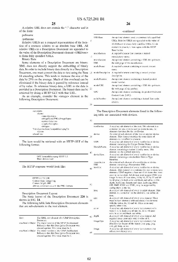
US 6,725,281 Bl 25
A relative URL does not contain the ":" character and is of the form:
pathname
/pathname Relative URLS are a compact representation of the loca
tion of a resource relative to an absolute base URL. All relative URLs in a Description Document are appended to the value of the Description Document element <URLbase> to form fully qualified URLs.
Binary Data Some elements of a Description Document are binary.
XML does not directly support the embedding of binary data. In order to include binary data directly in a Description Document, one must convert the data to text using the Base 64 encoding scheme. This tends to increase the size of the data by 25% on the average. Much of this overhead can be eliminated if the binary data is passed by reference instead of by value. To reference binary data, a URL to the data is provided in a Description Document. The binary data can be retrieved by doing a HTTP GET with that URL.
As an example, consider the <image> element in the following Description Document:
<iconList> <icon>
<size> 16</size> <imageType>PNG</imageType> <color>1</color> <depth>8</depth> <image>
"http:/ /device.! ocal/iconpath/icon. png" /> </icon>
</iconList>
The icon would be retrieved with an HTTP GET of the following format:
GET iconpath/icon.png HITP 1.1 Host: device.local
The HTTP response would look like:
HTTP/1.1 200 OK Content-Type: image/png Content-length: ### <binary color icon data in the PNG format>
Description Document Layout The basic layout of the Description Document 226 is
shown in FIG. 14. The following table lists Description Document elements
that are sub-elements to the root element.
Root The XML root element of a UPnP Description Document.
specVersionMajor The major version of the UPnP Architectural Reference that this Description Document was created against. This value must be 1.
specVersionMajor The minor version of the UPnP Architectural Reference that this Description Document was created against. This value must be 0.
5
10
15
20
25
30
35
40
45
50
55
URLBase
manufacturer
manufacturer
URL
modelName
26
-continued
An optional element used to construct fully qualified
URLs. Relative URLS are appended to the value of
<URLBase> to create fully qualified URLs. If this
element is present, it must agree with the HITP
Base header.
A required element that contains a textual
manufacturer name.
An optional element containing a URL that points to
the web page of the manufacturer.
A required element containing a textual product
name.
modelDescription A required element containing a textual product
description.
modelNumber
modelURL
UPC
serialNumber
An optional element containing a textual product
model number.
An optional element containing a URL that points to
the web page of the product.
An optional element containing the product Universal
Product Code (UPC).
An optional element containing a textual item serial
number.
The Description Document elements listed in the following table are associated with devices.
rootDevice
device
UDN
friendlyName
device Type
presentation URL iconList
icon
size
color
A required sub element of the root. This element is a container for one or more service elements and the elements that describe the rootDevice. An optional sub element of the root or another device element. This element contains the same kinds of elements as a rootDevice element. A required sub element of every rootDevice or device element containing the Unique Device Name. A required sub element of every rootDevice or device element containing a textual friendly name. This element can be updated remotely. A required sub element of every rootDevice or device element containing a standardized Device Type Identifier. An optional sub element of a rootDevice or device element containing a Presentation URL. A required sub element of every rootDevice or device element. This element is a container for one or more icon elements. UPnP requires a base set of six icons that must exist in the iconList. All devices must support PNG icon image formats of three sizes, 16 by 16, 32 by 32 and 48 by 48 pixels in both color and black and white at 8 bit depth. Additional formats and sizes, including JPEG, GIF, BMP, ICON and VML, may be supported by adding them to the list. A required sub element of every iconList element. This element is a container for the elements that define an icon. A required sub element of every icon element. There must be icon elements with associated size elements with the values 16, 32 and 48. Other icons may specify other sizes. A required sub element of every icon element with value 0 or 1. Each icon of size 16, 32 or 48 must exist in color and black and white.
60 depth A required sub element of every icon element. All required icons must exist with a value of 8.
image Type
image
65
A required sub element of every icon element that identifies the format of the binary icon: png, jpeg, vml, gif, bmp, or ico. A required sub element of every icon element that references a binary icon.
62
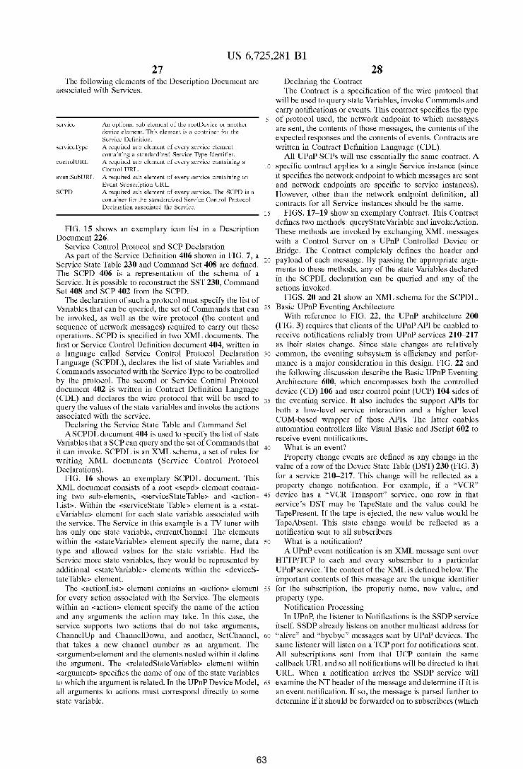
US 6,725,281 Bl 27
The following elements of the Description Document are associated with Services.
28 Declaring the Contract The Contract is a specification of the wire protocol that
will be used to query state Variables, invoke Commands and carry notifications or events. This contract specifies the type
service
service Type
An optional sub element of the rootDevice or another device element. This element is a container for the Service Definition. A required sub element of every service element containing a standardized Service Type Identifier.
5 of protocol used, the network endpoint to which messages are sent, the contents of those messages, the contents of the expected responses and the contents of events. Contracts are written in Contract Definition Language (CDL).
All UPnP SCPs will use essentially the same contract. A controlURL
eventSubURL
SCPO
A required sub element of every service containing a Control URL. A required sub element of every service containing an Event Subscription URL. A required sub element of every service. The SCPD is a container for the standardized Service Control Protocol Declaration associated the Service.
10 specific contract applies to a single Service instance (since it specifies the network endpoint to which messages are sent and network endpoints are specific to service instances). However, other than the network endpoint definition, all contracts for all Service instances should be the same.
FIG. 15 shows an exemplary icon list in a Description Document 226.
Service Control Protocol and SCP Declaration
15 FIGS. 17-19 show an exemplary Contract. This Contract defines two methods: queryState Variable and invokeAction. These methods are invoked by exchanging XML messages with a Control Server on a UPnP Controlled Device or Bridge. The Contract completely defines the header and
As part of the Service Definition 406 shown in FIG. 7, a Service State Table 230 and Command Set 408 are defined. The SCPD 406 is a representation of the schema of a Service. It is possible to reconstruct the SST 230, Command Set 408 and SCP 402 from the SCPD.
20 payload of each message. By passing the appropriate arguments to these methods, any of the state Variables declared in the SCPDL declaration can be queried and any of the actions invoked.
The declaration of such a protocol must specify the list of Variables that can be queried, the set of Commands that can 25
be invoked, as well as the wire protocol (the content and sequence of network messages) required to carry out these operations. SCPD is specified in two XML documents. The first or Service Control Definition document 404, written in a language called Service Control Protocol Declaration 30
Language (SCPDL), declares the list of state Variables and Commands associated with the Service Type to be controlled by the protocol. The second or Service Control Protocol document 402 is written in Contract Definition Language (CDL) and declares the wire protocol that will be used to 35 query the values of the state variables and invoke the actions associated with the service.
Declaring the Service State Table and Command Set ASCPDL document 404 is used to specify the list of state
Variables that a SCP can query and the set of Commands that 40 it can invoke. SCPDL is an XML schema, a set of rules for
writing XML documents (Service Control Protocol Declarations).
FIG. 16 shows an exemplary SCPDL document. This XML document consists of a root <scpd> element containing two sub-elements, <serviceStateTable> and <action- 45
List>. Within the <serviceState Table> element is a <stat-e Variable> element for each state variable associated with the service. The Service in this example is a TV tuner with has only one state variable, currentChannel. The elements within the <state Variable> element specify the name, data 50
type and allowed values for the state variable. Had the Service more state variables, they would be represented by additional <state Variable> elements within the <deviceS-
FIGS. 20 and 21 show an XML schema for the SCPDL. Basic UPnP Eventing Architecture
With reference to FIG. 22, the UPnP architecture 200 (FIG. 3) requires that clients of the UPnP API be enabled to receive notifications reliably from UPnP services 210--217 as their states change. Since state changes are relatively common, the eventing subsystem is efficiency and performance is a major consideration in this design. FIG. 22 and the following discussion describe the Basic UPnP Eventing Architecture 600, which encompasses both the controlled device (CD) 106 and user control point (UCP) 104 sides of the eventing service. It also includes the support APis for both a low-level service interaction and a higher level COM-based wrapper of those APis. The latter enables automation controllers like Visual Basic and JScript 602 to receive event notifications.
What is an event? Property change events are defined as any change in the
value of a row of the Device State Table (DST) 230 (FIG. 3) for a service 210-217. This change will be reflected as a property change notification. For example, if a "VCR" device has a "VCR Transport" service, one row in that service's DST may be TapeState and the value could be TapePresent. If the tape is ejected, the new value would be TapeAbsent. This state change would be reflected as a notification sent to all subscribers.
What is a notification? A UPnP event notification is an XML message sent over
HTTP/TCP to each and every subscriber to a particular UPnP service. The content of the XML is defined below. The
tateTable> element. The <actionList> element contains an <action> element
for every action associated with the Service. The elements within an <action> element specify the name of the action and any arguments the action may take. In this case, the service supports two actions that do not take arguments, ChannelUp and ChannelDown, and another, SetChannel, that takes a new channel number as an argument. The <argument>element and the elements nested within it define the argument. The <relatedState Variable> element within <argument> specifies the name of one of the state variables
important contents of this message are the unique identifier 55 for the subscription, the property name, new value, and
property type. Notification Processing In UPnP, the listener to Notifications is the SSDP service
itself. SSDP already listens on another multicast address for 60 "alive" and "byebye" messages sent by UPnP devices. The
same listener will listen on a TCP port for notifications sent. All subscriptions sent from that UCP contain the same callback URL and so all notifications will be directed to that URL. When a notification arrives the SSDP service will
to which the argument is related. In the UPnP Device Model, 65
all arguments to actions must correspond directly to some state variable.
examine the NT header of the message and determine if it is an event notification. If so, the message is parsed further to determine if it should be forwarded on to subscribers (which
63
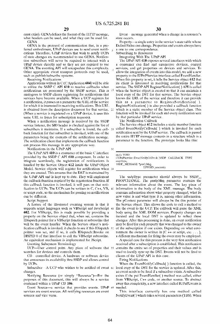
US 6,725,281 Bl 29
must exist). GENA defines the format of the HTTP message, what headers can be used, and what they can be used for.
30 Event-message generated when a change in a resource's
state occurs. GENA GENA is the protocol of communication that, in a pre
ferred embodiment, UPnP devices use to send event notifications. Therefore, UPnP devices that wish to notify UCPs of state changes are recommended to use GENA. Notification subscribers will never be required to interact with a UPnP device directly and so they are not required to use GENA The eventing API will encapsulate this complexity. Other appropriate event transport protocols may be used, such as publish/subscribe systems.
Property-a single entry in the service's state table whose Default Value can change. Properties and events always have
5 a one to one correspondence. Subscribing to Resources
Integrating With The UPnP API The UPnP API 410 exposes several interfaces with which
a consumer can find and enumerate devices, control
Receiving Notifications Applications written in C ( C Application 604) will be able
to utilize the SSBP C API 610 to receive callbacks when notifications are processed by the SSDP service. This is analogous to SSDP clients registering for notifications that services have become available. When a UCP registers for
10 services, and get properties on devices and services. To allow the integration of events into this model, we add a new property to the IUPnPService interface called EventHandler. When this property is set, it tells the Service object 612 that its client is interested in receiving notifications for that service. The SSDP API Register Notification() API is called
a notification, it passes as a parameter the URL of the service for which it is interested in receiving notifications. This URL is obtained from the description document for that service. (When a service is registered on a UPnP device, it uses this same URL to listen for subscription requests).
15 when the Service object is created so that it can maintain a local copy of the DST for that service. The Service object knows the URL of the service and therefore it can provide this as a par arne ter to Regis terN otifica tion( ) . RegisterNotification( ) is also provided a callback function
20 which is a static member of the Service object class. This function will be invoked for each and every notification sent by that particular UPnP service.
When a notification message is received by the SSDP service listener, the SID header is checked against the list of subscribers it maintains. If a subscriber is found, the call- 25
back function for that subscriber is invoked, with one of the parameters being the contents of the notification message. The notification client that implements the callback function can process this message in any appropriate way.
Notifications in the UPnP API 30
The UPnP API 410 is a consumer of the basic C interface provided by the SSDP C API 610 component. In order to integrate seamlessly, the registration of notifications is handled by the Service Object 612 inside the UPnP Object Model. Service objects will register for notifications when 35
they are created. This ensures that the DST is maintained by the UPnP API and is kept up to date. They will implement the callback function required by the registration function. If this callback function is invoked, it will pass on that notification to UCPs. The UCPs can be written in C, C++, VB, 40
or script code, so the mechanism for passing on notifications can be different.
Script Support A feature of the illustrated eventing system is that it
supports script languages such as VBScript and JavaScript 45
602. For VBScript, this is made possible by providing a property on the Service object that, when set, contains the !Dispatch pointer for a VBScript function or subroutine that will be the event handler. When the Service object's notification callback is invoked, it checks to see if this !Dispatch 50
pointer was set, and if so, it calls !Dispatch: :Invoke on DISPID 0 of that interface to call the VBScript subroutine. An equivalent mechanism is implemented for JScript.
Eventing Subsystem Terminology UCP-User control point. Any piece of software that 55
searches for devices and controls them. CD-controlled device. A hardware or software device
that announces its availability thru SSDP and allows control by UCPs.
Subscriber-A UCP who wishes to be notified of event 60
changes. Notifying Resource (or simply "Resource")-For the
purposes of this document, this will always be a service contained within a UPnP CD 106.
Event Source-a service that provides events. UPnP 65
services are event sources. All notifying resources are event sources and vice versa.
The Notification Callback The Service object 612 includes a static member function
called EventNotifyCallback( ) which is invoked for each notification sent by the UPnP service. The callback is passed the entire HTTP message contents in a structure which is a parameter to the function. The prototype looks like this:
static VOID CUPnPService::EventNotifyCallback (SSDP_CALLBACK_TYPE ssdpType, SSDP _MESSAGE *pssdpMsg,
LPVOID pcontext);
The ssdpType parameter should always be SSDP _ PROPCHANGE. The pssdpMsg parameter contains the relevant information about the event. The key piece of information is the body of the XML message. The body contains information about what property changed, what its new value is and what type it is, among other information. The pContext parameter will always be the this pointer of the Service object. This allows the code to call a method to fire the event to the UCP. The callback will parse the XML body using the XML DOM services. Property changes are iterated and the local DST is updated to reflect these changes. After this processing is done, an event notification may be fired for each property that was changed to the owner of the subscription if one exists. Depending on what environment the owner is written in (C ++ or script, etc .... ), a different mechanism for firing the event may be employed.
A special case for this process is the very first notification received after a subscription is established. This notification contains the entire set of properties and their values and is used to locally sync up the DST. Events will not be fired to clients of the UPnP API in this case.
Firing Notifications When the EventNotifyCallback( ) function is called, the
local copy of the DST for the service is updated. After this, an event needs to be fired if a subscriber exists. A subscriber exists if the put EventHandler( ) method was called, either from VBScript, C++ code, or another source. To abstract away this complexity, a new interface called IUPnPEvents is needed.
This interface currently has one method called Notify Event() which takes several parameters (TBS). When
64
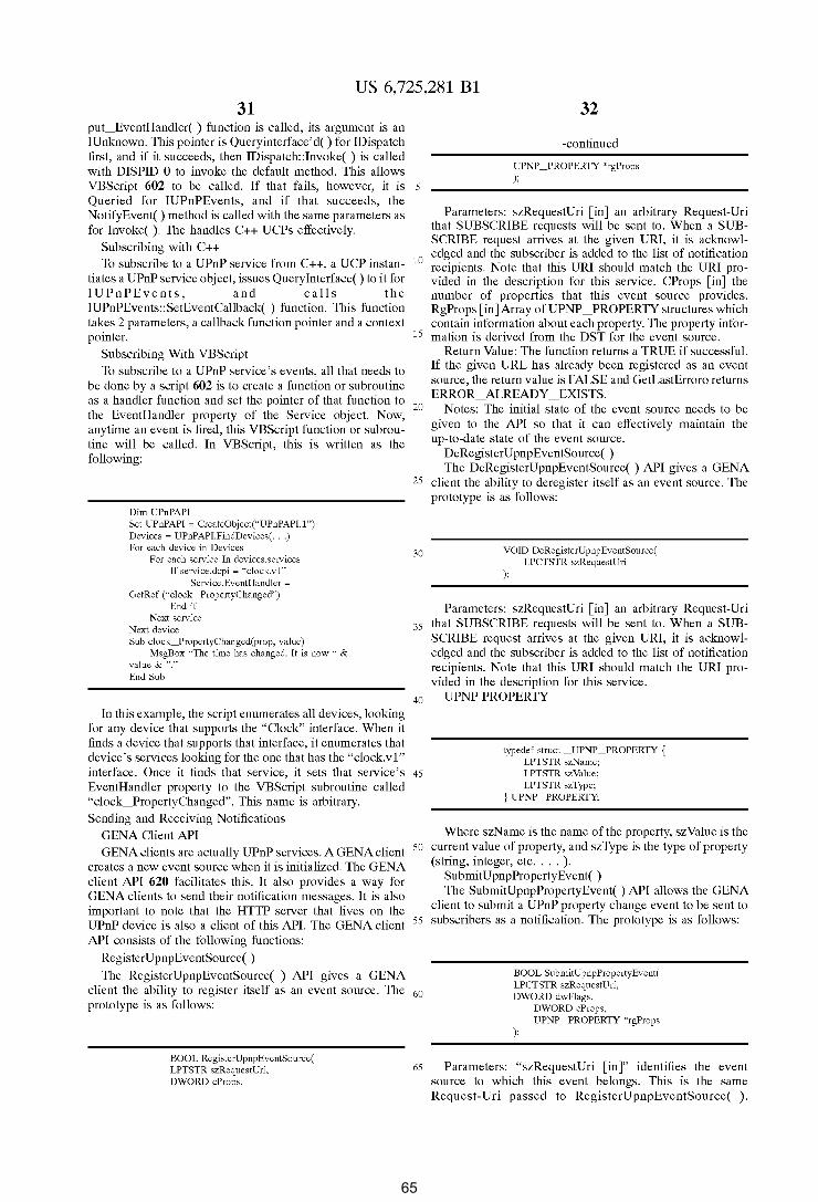
US 6,725,281 Bl 31
put_EventHandler( ) function is called, its argument is an !Unknown. This pointer is Queryinterface' d() for !Dispatch first, and if it succeeds, then !Dispatch: :Invoke( ) is called with DISPID 0 to invoke the default method. This allows VBScript 602 to be called. If that fails, however, it is 5
Queried for IUPnPEvents, and if that succeeds, the Notify Event() method is called with the same parameters as for Invoke( ). The handles C++ UCPs effectively.
Subscribing with C++
32
-continued
UPNP _PROPERTY *rgProps );
Parameters: szRequestUri [in] an arbitrary Request-Uri that SUBSCRIBE requests will be sent to. When a SUBSCRIBE request arrives at the given URI, it is acknowledged and the subscriber is added to the list of notification recipients. Note that this URI should match the URI provided in the description for this service. CProps [in] the
To subscribe to a UPnP service from C++, a UCP instan- 10
tiates a UPnP service object, issues Query Interface() to it for IUPnPEvents, and calls the IUPnPEvents::SetEventCallback( ) function. This function takes 2 parameters, a callback function pointer and a context pointer.
number of properties that this event source provides. RgProps [in]Array ofUPNP _PROPERTY structures which contain information about each property. The property infor-
15 mation is derived from the DST for the event source. Subscribing With VBScript To subscribe to a UPnP service's events, all that needs to
be done by a script 602 is to create a function or subroutine
Return Value: The function returns a TRUE if successful.
as a handler function and set the pointer of that function to 20
the EventHandler property of the Service object. Now, anytime an event is fired, this VBScript function or subroutine will be called. In VBScript, this is written as the
If the given URL has already been registered as an event source, the return value is FALSE and GetLastErroro returns ERROR_ALREADY _EXISTS.
Notes: The initial state of the event source needs to be given to the API so that it can effectively maintain the up-to-date state of the event source.
DeRegisterUpnpEventSource( ) following:
Dim UPnPAPI Set UPnPAPI ~ CreateObject("UPnPAPI.l") Devices ~ UPnPAPI.FindDevices( ... ) For each device in Devices
For each service In devices.services If service.dcpi ~ "clock.v1"
Service.EventHandler =
GetRef ("clock_PropertyChanged") End if
Next service Next device Sub clock_PropertyChanged(prop, value)
MsgBox "The time has changed. It is now " & value & "." End Sub
The DeRegisterUpnpEventSource( ) API gives a GENA 25 client the ability to deregister itself as an event source. The
prototype is as follows:
30 VOID DeRegisterUpnpEventSource( LPCTSTR szRequestUri
);
Parameters: szRequestUri [in] an arbitrary Request-Uri
35 that SUBSCRIBE requests will be sent to. When a SUBSCRIBE request arrives at the given URI, it is acknowledged and the subscriber is added to the list of notification recipients. Note that this URI should match the URI provided in the description for this service.
40 UPNP PROPERTY In this example, the script enumerates all devices, looking
for any device that supports the "Clock" interface. When it finds a device that supports that interface, it enumerates that device's services looking for the one that has the "clock.vl" interface. Once it finds that service, it sets that service's 45
EventHandler property to the VBScript subroutine called "clock_PropertyChanged". This name is arbitrary.
typedef struct _UPNP _PROPERTY { LPTSTR szName; LPTSTR szValue; LPTSTR szType;
} UPNP _PROPERTY;
Sending and Receiving Notifications GENA Client API GENA clients are actually UPnP services. A GENA client
creates a new event source when it is initialized. The GENA client API 620 facilitates this. It also provides a way for GENA clients to send their notification messages. It is also important to note that the HTTP server that lives on the UPnP device is also a client of this API. The GENA client API consists of the following functions:
RegisterUpnpEventSource( )
Where szName is the name of the property, szValue is the 50 current value of property, and szType is the type of property
(string, integer, etc .... ). SubmitUpnpPropertyEvent( ) The SubmitUpnpPropertyEvent( ) API allows the GENA
client to submit a UPnP property change event to be sent to 55 subscribers as a notification. The prototype is as follows:
The RegisterUpnpEventSource( ) API gives a GENA client the ability to register itself as an event source. The 60 prototype is as follows:
BOOL SubmitUpnpPropertyEvent( LPCTSTR szRequestUri, DWORD dwFlags,
DWORD cProps,
BOOL RegisterUpnpEventSource( LPTSTR szRequestUri, DWORD cProps,
UPNP _PROPERTY *rgProps );
65 Parameters: "szRequestUri [in]" identifies the event source to which this event belongs. This is the same Request-Uri passed to RegisterUpnpEventSource( ).
65
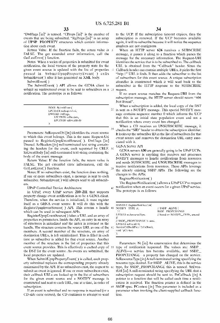
US 6,725,281 Bl 33
"DwFlags [in]" is unused. "CProps [in]" is the number of events that are being submitted. "RgProps [in]" is an array of UPNP _PROPERTY structures which contain information about each event.
Return Value: If the function fails, the return value is 5
FALSE. The get extended error information, call the GetLastError( ) function.
Notes: When a series of properties is submitted for event notification, the local version of the property state for the given event source is updated with the list of properties 10
passed in. SubmitUpnpPropertyEvent( ) calls SubmitEvent( ) after it has generated an XML body.
SubmitEvent( ) The SubmitEvent( ) API allows the GENA client to
submit an unstructured event to be sent to subscribers as a 15
notification. The prototype is as follows:
34 to the UCP. If the subscription timeout expires, then the subscription is removed. If the UCP becomes available again, it will re-subscribe because it will notice the sequence numbers are not contiguous.
When an HTTP server 626 receives a SUBSCRIBE message, it passes it along to a function which parses the message for the necessary information. The Request-URI identifies the service that is to be subscribed to. The callback URL is obtained from the "Callback" header. Since the Callback header can contain multiple URLs, it picks the first "http://" URL it finds. It then adds the subscriber to the list of subscribers for this event source. A unique subscription identifier is constructed which it will send back to the subscriber in the HTTP response to the SUBSCRIBE request.
If no event source matches the Request-URI from the subscription message, the HTTP server should return "404 Not Found".
When a subscription is added, the local copy of the DST BOOL SubmitEvent( LPCfSTR szRequestUri, DWORD dwFlags,
);
LPCTSTR szHeaders, LPCTSTR szEventBody
20 is sent as a NOTIFY message. This special NOTIFY message contains sequence number 0 which informs the UCP that this is an initial state population event and not a notification where every event has changed.
When a CD receives an UNSUBSCRIBE message, it
Parameters: SzRequestUri [in] identifies the event source 25 checks the "SID" header to obtain the subscription identifier.
to which this event belongs. This is the same Request-Uri passed to RegisterUpnpEventSource( ). DwFlags [in] Unused. SzHeaders [in] null-terminated text string containing the headers for the event, each separated by CRLF. 30
SzEventBody [in] null-terminated text string containing the body of the event message
It looks up the subscriber ID in the list of subscribers for that event source and removes the destination URL entry associated with it. GENA Server API
GENA servers 630 are generally going to be UPnP UCPs. A GENA server is anything that receives and processes NOTIFY messages to handle notifications from resources and sends SUBSCRIBE and UNSUBSCRIBE messages to
Return Value: If the function fails, the return value is FALSE. The get extended error information, call the GetLastError( ) function.
Notes: If no subscribers exist, the function does nothing. If one or more subscribers exist, a message is sent to each subscriber. SubmitEvent() will always send to all subscrib-
35 receive notifications from resources. These APis leverage the already existing SSDP APis. The following are the changes to the APis:
RegisterNotification( )
ers. UPnP Controlled Device Architecture
The RegisterNotification() allows a UPnP UCP to request
40 notification when an event occurs for a given UPnP service.
In UPnP, every UPnP service 210-211 that supports property change event notifications is to be a GENA client. Therefore, when the service is initialized, it must register itself as a GENA event source. It will do this with the RegisterUpnpEventSource( ) API. This returns a handle 45
which can be used in subsequent APis. RegisterUpnpEventSource() takes a URL and an array of
properties as parameters. Inside the API, an entry in an array
The prototype is as follows:
HANDLE RegisterNotification( NOTIFY_TYPE nt, I ?? LPTSTR szResourceType, if II SSDP _PROPCHANGE is used. LPTSTR szEventUrl, ServiceCallbackFunc fnCallback, void *pContext );
II SSDP_ALIVE I SSDP PROPCHANGE II based on NOTIFY_TYPE, unused
Parameters: Nt [in] An enumeration that determines the
of structures is initialized and the index is returned as the handle. The structure contains the source URL as one of the 50
members. A second member of the structure, an array of destination URLs, is left uninitialized. This is filled in each time as subscriber is added for that event source. Another member of the structure is the list of properties that this event source provides. This is effectively a cached copy of the DST for the event source. As events are submitted, the local properties are updated.
55 type of notification requested. The values are: SSDP _ ALIVE-a service has become available, and SSDP _ PROPCHANGE-a property has changed on the service. SzResourceType [in] A null-terminated string specifying the resource type desired. For SSDP _ALIVE, this is the service
When SubmitUpnpPropertyEvent( ) is called, each property submitted replaces the corresponding property already maintained by the API. If no subscribers exist, the request to submit an event is ignored. If one or more subscribers exist, their callback URLs are looked up in the list of subscribers for the given event source and a NOTIFY message is constructed and sent to each URL, one at a time, in order of subscription.
If an event is submitted and no response is received (or a CD-side error occurs), the CD continues to attempt to send
60 type, for SSDP _PROPCHANGE this is unused. SzEventUrl [in] A null-terminated string specifying the URL that a subscription request should be sent to. FnCallback [in] A pointer to a function that will be called each time a notification is received. The function pointer is defined in the
65 SSDP spec. PContext [in] This parameter is included as a parameter when invoking the client-supplied callback func-tion.
66
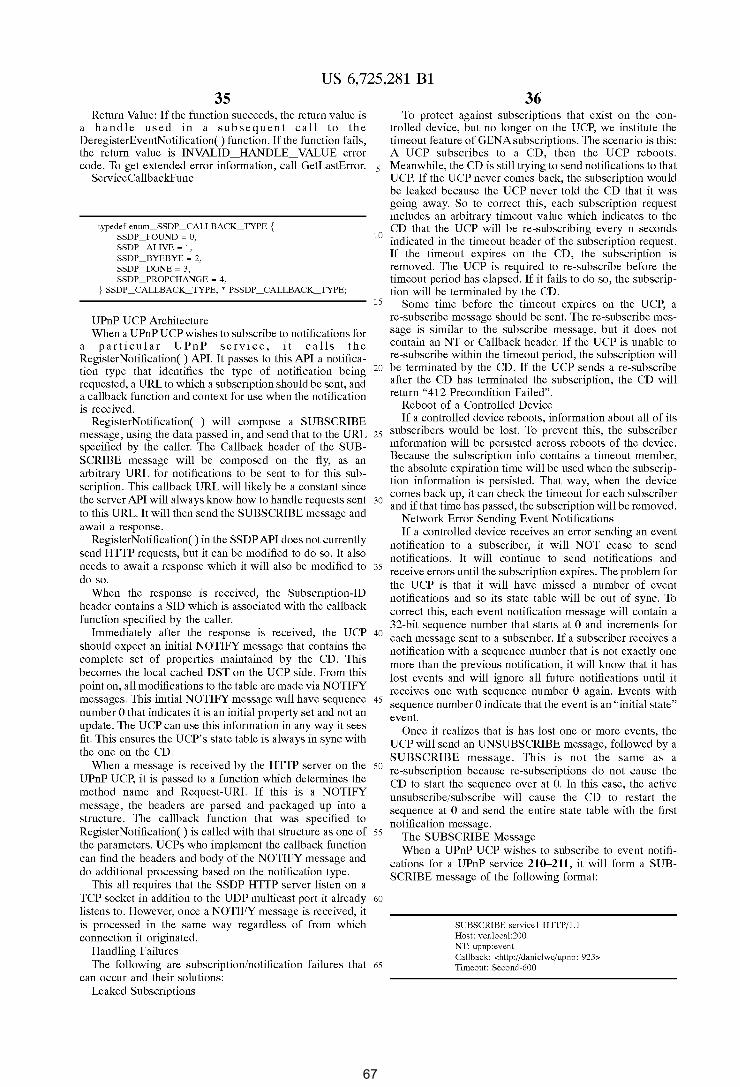
US 6,725,281 Bl 35
Return Value: If the function succeeds, the return value is a handle used in a subsequent call to the DeregisterEventNotification() function. If the function fails, the return value is INVALID_HANDLE_ VALUE error code. To get extended error information, call GetLastError. 5
ServiceCallbackFunc
36 To protect against subscriptions that exist on the con
trolled device, but no longer on the UCP, we institute the timeout feature of GENA subscriptions. The scenario is this: A UCP subscribes to a CD, then the UCP reboots. Meanwhile, the CD is still trying to send notifications to that UCP. If the UCP never comes back, the subscription would be leaked because the UCP never told the CD that it was going away. So to correct this, each subscription request includes an arbitrary timeout value which indicates to the
typedef enum_SSDP _CALLBACK_ TYPE { SSDP _FOUND ~ 0, SSDP _ALIVE ~ 1, SSDP _BYEBYE ~ 2, SSDP _DONE ~ 3, SSDP _PROPCHANGE ~ 4,
10 CD that the UCP will be re-subscribing every n seconds indicated in the timeout header of the subscription request. If the timeout expires on the CD, the subscription is removed. The UCP is required to re-subscribe before the timeout period has elapsed. If it fails to do so, the subscrip-
} SSDP _CALLBACK_ TYPE, * PSSDP _CALLBACK_ TYPE;
UPnP UCP Architecture When a UPnP UCP wishes to subscribe to notifications for
15 tion will be terminated by the CD.
Some time before the timeout expires on the UCP, a re-subscribe message should be sent. The re-subscribe message is similar to the subscribe message, but it does not contain an NT or Callback header. If the UCP is unable to re-subscribe within the timeout period, the subscription will
a particular UPnP service, it calls the Register Notification() API. It passes to this API a notification type that identifies the type of notification being requested, a URL to which a subscription should be sent, and a callback function and context for use when the notification
20 be terminated by the CD. If the UCP sends a re-subscribe after the CD has terminated the subscription, the CD will return "412 Precondition Failed".
is received. RegisterNotification( ) will compose a SUBSCRIBE
message, using the data passed in, and send that to the URL 25
specified by the caller. The Callback header of the SUBSCRIBE message will be composed on the fly, as an arbitrary URL for notifications to be sent to for this subscription. This callback URL will likely be a constant since the server API will always know how to handle requests sent 30
to this URL. It will then send the SUBSCRIBE message and await a response.
Reboot of a Controlled Device If a controlled device reboots, information about all of its
subscribers would be lost. To prevent this, the subscriber information will be persisted across reboots of the device. Because the subscription info contains a timeout member, the absolute expiration time will be used when the subscription information is persisted. That way, when the device comes back up, it can check the timeout for each subscriber and if that time has passed, the subscription will be removed.
Network Error Sending Event Notifications If a controlled device receives an error sending an event
notification to a subscriber, it will NOT cease to send notifications. It will continue to send notifications and
RegisterNotification() in the SSDP API does not currently send HTTP requests, but it can be modified to do so. It also needs to await a response which it will also be modified to do so.
When the response is received, the Subscription-ID header contains a SID which is associated with the callback function specified by the caller.
35 receive errors until the subscription expires. The problem for the UCP is that it will have missed a number of event notifications and so its state table will be out of sync. To correct this, each event notification message will contain a 32-bit sequence number that starts at 0 and increments for each message sent to a subscriber. If a subscriber receives a notification with a sequence number that is not exactly one
Immediately after the response is received, the UCP 40
should expect an initial NOTIFY message that contains the complete set of properties maintained by the CD. This becomes the local cached DST on the UCP side. From this point on, all modifications to the table are made via NOTIFY messages. This initial NOTIFY message will have sequence number 0 that indicates it is an initial property set and not an update. The UCP can use this information in any way it sees
more than the previous notification, it will know that it has lost events and will ignore all future notifications until it receives one with sequence number 0 again. Events with
45 sequence number 0 indicate that the event is an "initial state" event.
fit. This ensures the UCP's state table is always in sync with the one on the CD.
When a message is received by the HTTP server on the UPnP UCP, it is passed to a function which determines the method name and Request-URI. If this is a NOTIFY message, the headers are parsed and packaged up into a structure. The callback function that was specified to Register Notification() is called with that structure as one of the parameters. UCPs who implement the callback function can find the headers and body of the NOTIFY message and do additional processing based on the notification type.
Once it realizes that is has lost one or more events, the UCP will send an UNSUBSCRIBE message, followed by a SUBSCRIBE message. This is not the same as a
50 re-subscription because re-subscriptions do not cause the CD to start the sequence over at 0. In this case, the active unsubscribe/subscribe will cause the CD to restart the sequence at 0 and send the entire state table with the first notification message.
55 The SUBSCRIBE Message
This all requires that the SSDP HTTP server listen on a TCP socket in addition to the UDP multicast port it already 60
listens to. However, once a NOTIFY message is received, it
When a UPnP UCP wishes to subscribe to event notifications for a UPnP service 210--211, it will form a SUBSCRIBE message of the following format:
is processed in the same way regardless of from which connection it originated.
Handling Failures The following are subscription/notification failures that 65
can occur and their solutions: Leaked Subscriptions
SUBSCRIBE service1 HTIP/1.1 Host: vcr.local:200 NT: upnp:event Callback: <http://danielwe/upnp: 923> Timeout: Second-600
67
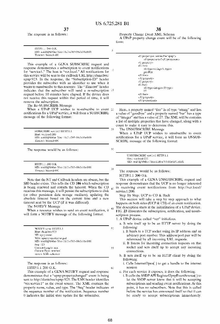
US 6,725,281 Bl 37
The response is as follows::
HITP/1.1 200 O.K. SID: uuid:kj9d4fae-7dec-11d0-a765-00a0c91e6bf6 Timeout: Second-600
5
This example of a GENA SUBSCRIBE request and response demonstrates a subscription to event notifications for "servicel." The host is "vcr.local." All notifications for 10
this service will be sent to the callback URL http://danielwe/ upnp:923. In the response, the "Subscription-ID" header provides the subscriber with an identifier to use when it wants to unsubscribe to this resource. The "Timeout" header indicates that the subscriber will send a re-subscription 15
request before 10 minutes have elapsed. If the device does not receive this request within that period of time, it will remove the subscription.
The Re-SUBSCRIBE Message When a UPnP UCP wishes to re-subscribe to event 20
notifications for a UPnP service, it will form a SUBSCRIBE message of the following format:
SUBSCRIBE service1 HITP/1.1 Host: vcr.local:200 SID: uuid:kj9d4fae-7dec-11d0-a765-00a0c91e6bf6 Timeout: Second-600
The response would be as follows::
HITP/1.1 200 O.K. SID: uuid:kj9d4fae-7dec-11d0-a765-00a0c91e6bf6 Timeout: Second-600
25
30
35
38 Property Change Event XML Schema A UPnP property change event will be of the following
form:
<U:propertyset xmlns:U~"upnp""> < U :propcount> 2</U :propcount>
<U:property> <U:foo>
<U:type>string</U:type> goodbye
</U:foo> </U :property> <U:property> <U:bar>
<U:type>integer</U:type> 27
</U:bar> </U :property> </U :propertyset>
Here, a property named "foo" is of type "string" and has a value of "goodbye" and a property named "bar" has a type of "integer" and has a value of 27. The XML will be contains a list of multiple properties that have changed, along with a count to make it easy to determine this.
The UNSUBSCRIBE Message When a UPnP UCP wishes to unsubscribe to event
notifications for a UPnP service, it will form an UNSUBSCRIBE message of the following format:
UNSUBSCRIBE service1 HITP/1.1 Host: vcr.local :200 SID: uuid:kj9d4fae-7dec-11d0-a 765-00a0c91e6bf6
The response would be as follows:: HTTP /1.1 200 0 .k.
Note that the NT and Callback headers are absent, but the SID header exists. This tells the CD 106 which subscription is being renewed and restarts the timeout. When the CD receives this message, it will persist the subscriptions to disk (or other persistent data storage medium), updating the absolute timeout based on the current time and a new timeout sent by the UCP (if it was different).
This example of a GENA UNSUBSCRIBE request and response demonstrates that the UCP is no longer interested
40 in receiving event notifications from http://vcr.local/ service1:200.
Step By Step: UCP to CD & Back
The NOTIFY Message When a resource wishes to send an event notification, it
will form a NOTIFY message of the following format:
This section will take a step by step approach to what happens on both sides (UCP & CD) of an event notification.
45 The description starts at the initialization of a UPnP device.
NOTIFY upnp HITP/1.1 Host: danielwe:923 NT: upnp:event NTS: upnp:propertychanged SID: uuid:kj9d4fae-7dec-11d0-a765-00a0c91e6bf6 Seq: 123 Content-Length: xxx Content-Type: text/xml <event XML schema>
The response is as follows:: HTTP/1.1 200 O.K.
50
55
60
This example of a GENA NOTIFY request and response demonstrates that a "upnp:propertychanged" event is being sent to http://danielwe/upnp:923. The USN header identifies "vcr.servicel" as the event source. The XML contains the property name, value, and type. The "Seq" header indicates 65
the sequence number of the notification. Sequence number 0 indicates the initial state update for the subscriber.
FIG. 23 illustrates the subscription, notification, and unsub-scription process. 1. A UPnP device called "vcr" initializes.
a. It sets itself up to be an HTTP server by doing the following: i. It binds to a TCP socket using its IP address and an
arbitrary port number. This address/port pair will be referenced by all incoming URL requests.
ii. It listens for incoming connection requests on that socket and sets itself up to accept any incoming connections.
b. It sets itself up to be an HTTP client by doing the following: i. Calls InternetOpen( ) to get a handle to the internet
sesswn c. For each service it exposes, it does the following:
i. It calls the SSDP API RegisterUpnpEventSource() to let the SSDP server know that it will be accepting subscriptions and sending event notifications. At this point, it has no subscribers. Note that this is called before the service has announced itself so that it can be ready to accept subscriptions immediately.
68

US 6,725,281 Bl 39
RegisterUpnpEventSource( ) sends no network traffic on the wire. It is a local initialization only. RegisterUpnpEventSource( ) does the following: 1. Adds a structure to the list of event sources
containing the following: 5 a. A URL to which subscribers will send sub
scription requests b. A list of destination URLs. A notification
message will be sent to each destination URL. c. The state table for the event source. This
10 structure contains the property name, value, and type for each property supported by the service.
ii. It calls the SSDP API RegisterService( ) to let the world know that it has become available. RegisterService( ) will send out an SSDP "alive" 15
message on the multicast channel that will be heard by any device running the SSDP service.
d. It starts sending events immediately, even without
~~~:c~~~~:~· ~:~hs~~~~~s~~~r:i::~~nt~pbdeat=t~!~ 1~~:~ 20
regard to adding subscribers, so between the time the SubmitEvent( ) API is called, and the time the local state table is updated, no subscriptions can be added or removed.
2. Meanwhile, a UPnP UCP initializes. a. It initializes its HTTP server, passively listening on a
TCPport.
25
b. If the UCP started up before the UPnP device initialized, it won't see any services become available. 30 When the device finally starts, the UCP will be notified.
c. Once the UPnP services have been announced the UCP will be able to access one or more of them.
d. The UCP drives the UPnP API to instantiate a UPnP Service Object. 35
e. The UPnP Service Object does the following when it is instantiated: i. It obtains the event subscription URL from the
description for that service. ii. It calls the SSDP API RegisterNotification() speci- 40
fying SSDP _PROPCHANGE as the event type, the event subscription URL, a callback function pointer (which is a static member function of the class), and a context pointer (which is the "this" pointer of the class). RegisterNotification( ) does the following: 45
1. It makes an LRPC call to the SSDP service. The rest happens on the service side.
2. If this is the first time it is called for SSDP PROPCHANGE notifications, RegisterNotification() will call InternetOpen() to 50
get a handle to an internet session. This handle is shared among all local UPnP UCPs.
3. It calls InternetConnect() passing the server name given in the URL it was passed.
4. It calls HttpOpenRequest() passing in the rest of 55
the URL it was passed. 5. The handles returned by these functions are saved
with the structure that maintains the subscription. 6. It composes a SUBSCRIBE message, using the
d at a p ass e d in , b y c a 11 in g 60
HttpAddRequestHeaders( ). It adds the "NT", "Callback", and "Timeout" headers. The Callback header of the SUBSCRIBE message will be composed on the fly, as an arbitrary URL for notifications to be sent to for this subscription. The 65
server name is the local IP address, and the port is the same one referred to by step 2a above.
40 7. It calls HttpSendRequest() to send the request to
the CD. This is a synchronous function that will return when the request has been responded to by the CD.
8. It calls HttpQueryinfo( ... , HTTP _QUERY_ CUSTOM, . . . ) to get the "Subscription-Id" header. The resulting SID will be stored with the subscription structure.
9. It calls HttpQueryinfo( ... , HTTP_QUERY_ CUSTOM, ... ) to get the "Timeout" header. The resulting timeout value will be stored with the subscription structure.
10. A timer is started for re-subscription based on the timeout value returned in the response. When the timer goes off, the re-subscription will be sent.
11. The SID, callback function pointer, and timeout values are stored in a structure that maintains the list of local subscriptions.
3. Back on the UPnP CD, the subscription request is received by the HTTP server. The following occurs: a. The request is parsed into URI, NT, Callback, and
Timeout fields. b. The NT field must match "upnp:event". If it doesn't, the
CD responds with "412 Precondition Failed." c. The URI identifies the event source. The URI is
converted into a URL and matched with the list of event sources registered on the CD. If no match is found, the CD responds with "404 Not Found".
d. If a match is found, the following occurs: i. The Callback URL is added to a list of subscriber
URLs. ii. The Timeout value is processed and an absolute time
is stored with the event source data. If this time expires and a re-subscribe message has not been received, the subscription is removed.
iii. Anew SID is created, and stored with the subscriber in the event source.
iv. A sequence number is initialized to 0. v. A subscription response is composed, including an
echo of the Timeout header and the SID just created. vi. The response is sent. vii. If the response is sent successfully, the list of event
sources is persisted to disk for recovery purposes. viii. A timer is started using the same timeout value as
the header echoed to the UCP. When this timer elapses, the subscription is removed. If the CD receives a re-subscribe request, this timer will be reset. In an ideal world, the timer will never elapse.
ix. An initial event notification is sent to initialize the UCP's state table. The following describes that process: 1. InternetOpen( ) is called if an existing internet
session handle does not exist. 2. InternetConnect( ) is called, passing the server
name specified in the callback URL for this subscription.
3. HttpOpenRequest() is called, passing in the rest of the callback URL.
4. A NOTIFY message is composed, using the data passed in, by calling HttpAddRequestHeaders( ). It adds the "NT", "NTS", "SID", "Seq", "ContentLength", and "Content-Type" headers. a. The NT header will always be "upnp:event".
The NTS header will always be "UPnP:propertychange".
b. The SID header contains the SID stored in the event source structure
69
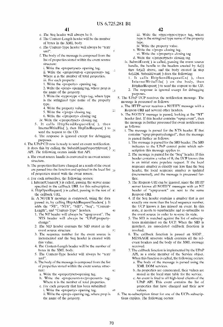
US 6,725,281 Bl 41
c. The Seq header will always be 0. d. The Content-Length header will be the number
of bytes in the XML body. e. The Content-Type header will always be "text/
xml". f. The body of the message is composed from the
list of properties stored within the event source structure:
5
i. Write the <propertyset> opening tag. ii. Write the <propcount>n </propcount> tag. 10
Where n is the number of total properties. iii. For each property: 1. Write the <property> opening tag. 2. Write the <prop> opening tag, where prop is the name of the property. 15
3. Write the <type>type </typ> tag, where type is the stringized type name of the property type. 4. Write the property value. 5. Write the </prop> closing tag. 6. Write the </property> closing tag
iv. Write the </propertyset> closing tag
20
5. It calls HttpSendRequestEx( ), then InternetWriteFile( ), then HttpEndRequest( ) to send the request to the CD. 25
6. The response is ignored except for debugging purposes.
4. The UPnP CD now is ready to send an event notification. It does this by calling the SubmitUpnpPropertyEvent( ) API. The following occurs inside that API: 30
a. The event source handle is converted to an event source structure.
b. The properties that have changed as a result of the event are passed into the function and updated in the local list 35 of properties stored with the event source.
c. For each subscriber, the following occurs: i. InternetConnect( ) is called, passing the server name
specified in the callback URL for this subscription. ii. HttpOpenRequest( ) is called, passing in the rest of 40
the callback URL. iii. A NOTIFY message is composed, using the data
passed in, by calling HttpAddRequestHeaders( ). It adds the "NT", "NTS", "SID", "Seq", "Content-Length", and "Content-Type" headers. 45
1. The NT header will always be "upnp:event". The NTS header will always be "UPnP:propertychange".
2. The SID header contains the SID stored in the event source structure 50
3. The sequence number for the event source is incremented and the Seq header is created with this value.
4. The Content-Length header will be the number of bytes in the XML body. 55
5. The Content-Type header will always be "text/ xml".
6. The body of the message is composed from the list of properties stored within the event source struc-ture: 60
a. Write the <propertyset>opening tag. b. Write the <propcount>n</propcount> tag.
Where n is the number of total properties. c. For each property that has been submitted:
i. Write the <property> opening tag. 65
ii. Write the <prop> opening tag, where prop is the name of the property.
42 iii. Write the <type>type</type> tag, where type is the stringized type name of the property type. iv. Write the property value.
v. Write the </prop> closing tag. vi. Write the </property> closing tag
d. Write the </propertyset> closing tag iv. SubmitEvent( ) is called, passing the event source
handle, the handle to the headers created by 4c(i) thru 4c(iii) above, and the body created in step 4c(iii)6. SubmitEvent( ) does the following: 1. It calls HttpSendRequestEx( ), then
InternetWriteFile( ) on the body, then HttpEndRequest() to send the request to the CD.
2. The response is ignored except for debugging purposes.
5. The UPnP UCP receives the notification message. The message is processed as follows: a. The HTTP server receives a NOTIFY message with a
Request-URI and several other headers. b. The NOTIFY message is parsed, looking at the "NT"
header first. If this header contains "upnp:event", then the message is further processed for event notifications as follows: i. The message is parsed for the NTS header. If that
contains "upnp:propertychanged", then the message is parsed further as follows: 1. The message is parsed for the SID header. The SID
indicates to the UPnP control point which subscription this message applies to.
2. The message is parsed for the "Seq" header. If this header contains a value of 0, the UCP knows this is an initial state populate request. If the local sequence number is exactly one less than the Seq header, the local sequence number is updated (incremented), and the message is processed further.
3. The Request-URI can be ignored, since the HTTP server knows all NOTIFY messages with an NT header of "upnp:event" are sent to the same Request-URI.
4. If the Seq header contains a number that is not exactly one more than the local sequence number, the UCP knows it has missed an event. In this state, it needs to unsubscribe and re-subscribe to the event source in order to re-sync its state.
5. The SID is matched against the list of subscriptions maintained on the UCP. When the SID is matched, its associated callback function is invoked.
6. The callback function is passed an SSDP MESSAGE structure which contains all the relevant headers and the body of the XML message received.
7. The callback function is implemented by the UPnP API, as a static member of the Service object. When this function is called, the following occurs: a. The body of the message is parsed using the
XML DOM services. b. As properties are enumerated, their values are
stored in the local state table for the service. c. An event is fired to all high-level clients of the
UPnP API. This event contains the list of properties that have changed and their new values.
6. The re-subscription timer for one of the UCPs subscriptions expires. The following occurs:
70
US 6,725,281 Bl 43
a. A re-subscribe message is composed. This message is very similar to a subscribe message except in doesn't include an NT or Callback header, but it does have a SID header.
b. The request is sent to the CD. c. The response contains the new timeout value. d. The timer is reset with this timeout.
UCP State Synchronization Models CD-initiated NeedsSync Method This method begins with the CD sending its initial state to
the subscriber the first time an event is submitted by the service. UCPs will subscribe to the service first, then receive notifications for events as they occur. The first event will happen to be the initial state of the service. The UCP state table will always be in sync with this method.
When the CD sends a notification to a subscriber and receives an error. In this case, it marks the subscriber as "NeedsSync" and the next time an event is submitted, all events are sent to the subscriber. The problem with this is that the API needs to keep track of which subscribers need syncing and which ones don't. The client of this API (the UPnP service) would need to send separate messages to each subscriber and know which ones needed all events and which ones just wanted the ones that changed.
UCP-initiated sync This method states that the UCP should subscribe to event
notifications, then call a function that obtained the state from the service. This means that any events that were received in the meantime would need to be matched against the incoming set of events and replaced if they were older. This method leads to synchronization issues where the UCP may receive events that are newer but when it queries for the state, it gets an older view of the table. This requires using sequence numbers to determine which information is newer. If the view of the table received by the query is too old, it has to be discarded. Alternatively, the properties that were not received by event notification would not be overwritten, but all other properties would be. Using sequence numbers make this more complicated.
CD-initiated sync This preferred method takes a simpler approach. Any time
the UCP subscribes to a service, the service will immediately afterwards, send the entire contents of the state table with the first notification. This precludes the UCP from making a query for the state table. Subsequent events update the local state table on the UCP. If the connection is lost, the UCP will lose its subscription. If the UCP realizes it has not received an event after a certain amount of time has elapsed, it will re-subscribe. At that point, the CD will re-send the entire state table again, and the UCP is ensured to be up to date. Exemplary Computer Hardware
FIG. 24 and the following discussion are intended to provide a brief, general description of a suitable computer which may be used in the above described UPnP device control model. This conventional computer 820 (such as personal computers, laptops, palmtops or handheld-Pes, set-tops, servers, mainframes, and other variety computers) includes a processing unit 821, a system memory 822, and
44 The system bus may be any of several types of bus
structure including a memory bus or memory controller, a peripheral bus, and a local bus using any of a variety of conventional bus architectures such as PCI, VESA, AGP,
5 Microchannel, ISA and EISA, to name a few. The system memory includes read only memory (ROM) 824 and random access memory (RAM) 825. A basic input/output system (BIOS), containing the basic routines that help to transfer information between elements within the computer
10 820, such as during start-up, is stored in ROM 824. The computer 820 further includes a hard disk drive 827,
a magnetic disk drive 828, e.g., to read from or write to a removable disk 829, and an optical disk drive 830, e.g., for reading a CD-ROM disk 831 or to read from or write to other
15 optical media. The hard disk drive 827, magnetic disk drive 828, and optical disk drive 830 are connected to the system bus 823 by a hard disk drive interface 832, a magnetic disk drive interface 833, and an optical drive interface 834, respectively. The drives and their associated computer-
20 readable media provide nonvolatile storage of data, data structures, computer-executable instructions, etc. for the computer 820. Although the description of computerreadable media above refers to a hard disk, a removable magnetic disk and a CD, it should be appreciated by those
25 skilled in the art that other types of media which are readable by a computer, such as magnetic cassettes, flash memory cards, digital video disks, Bernoulli cartridges, and the like, may also be used in the exemplary operating environment.
A number of program modules may be stored in the drives 30 and RAM 825, including an operating system 835, one or
more application programs 836, other program modules 837, and program data 838.
A user may enter commands and information into the computer 820 through a keyboard 840 and pointing device,
35 such as a mouse 842. Other input devices (not shown) may include a microphone, joystick, game pad, satellite dish, scanner, or the like. These and other input devices are often connected to the processing unit 821 through a serial port interface 846 that is coupled to the system bus, but may be
40 connected by other interfaces, such as a parallel port, game port or a universal serial bus (USB). A monitor 847 or other type of display device is also connected to the system bus 823 via an interface, such as a video adapter 848. In addition to the monitor, computers typically include other peripheral
45 output devices (not shown), such as speakers and printers. The computer 820 operates in a networked environment
using logical connections to one or more remote computers, such as a remote computer 849. The remote computer 849 may be a server, a router, a peer device or other common
50 network node, and typically includes many or all of the elements described relative to the computer 820, although only a memory storage device 850 has been illustrated in FIG. 24. The logical connections depicted in FIG. 24 include a local area network (LAN) 851 and a wide area network
55 (WAN) 852. Such networking environments are commonplace in offices, enterprise-wide computer networks, intranets and the Internet.
a system bus 823 that couples various system components including the system memory to the processing unit 821. The processing unit may be any of various commercially 60
available processors, including Intel x86, Pentium and compatible microprocessors from Intel and others, including Cyrix, AMD and Nexgen; Alpha from Digital; MIPS from MIPS Technology, NEC, IDT, Siemens, and others; and the PowerPC from IBM and Motorola. Dual microprocessors 65
and other multi-processor architectures also can be used as the processing unit 821.
When used in a LAN networking environment, the computer 820 is connected to the local network 851 through a network interface or adapter 853. When used in a WAN networking environment, the computer 820 typically includes a modem 854 or other means for establishing communications (e.g., via the LAN 851 and a gateway or proxy server 855) over the wide area network 852, such as the Internet. The modem 854, which may be internal or external, is connected to the system bus 823 via the serial port interface 846. In a networked environment, program
71
US 6,725,281 Bl 45
modules depicted relative to the computer 820, or portions thereof, may be stored in the remote memory storage device. It will be appreciated that the network connections shown are exemplary and other means of establishing a communications link between the computers may be used.
In accordance with the practices of persons skilled in the
46 (including satellite, cell, pager, commercial signal sideband, etc.), power line carrier (PLC), phone line, and television cable, among others.
With reference now to FIG. 26, the embedded computing 5 device 100 (FIG. 25) has a software architecture 120 that
conforms to the above described UPNP device control model. UPNP provides a mechanism for the embedded computing device to operate in the Internet, as well as networks that have no administrator and no connection to
art of computer programming, the present invention is described below with reference to acts and symbolic representations of operations that are performed by the computer 820, unless indicated otherwise. Such acts and operations 10
are sometimes referred to as being computer-executed. It will be appreciated that the acts and symbolically represented operations include the manipulation by the processing unit 821 of electrical signals representing data bits which causes a resulting transformation or reduction of the electrical signal representation, and the maintenance of data bits
the Internet, and hence no access to configuration services like the Dynamic Host Configuration Protocol (DHCP). DHCP is a mechanism for providing devices with configuration information needed to access the Internet. The mecha-nism functions through the use of a multicast request for
15 configuration information that is generally responded to with an IP address and DNS server location. Additional informa-
at memory locations in the memory system (including the system memory 822, hard drive 827, floppy disks 829, and CD-ROM 831) to thereby reconfigure or otherwise alter the computer system's operation, as well as other processing of 20
signals. The memory locations where data bits are maintained are physical locations that have particular electrical, magnetic, or optical properties corresponding to the data bits.
tion can only be returned in the response. In non-configured (ad-hoc) networks, UPNP uses the
AutoiP protocol. AutoiP is an enhancement to DHCP that allows devices to
claim IP addresses in the absence of a DHCP server or similar IP configuration authority. IP addresses are claimed from a reserved range that is not allowed to be transmitted on the open Internet; thus they are only good for the local
Exemplary Embedded Computing Device FIGS. 25 and 26 are intended to provide a brief, general
description of a suitable embedded computing device 900 which may be used in the illustrated implementation of the invention. The embedded computing device 900 can be any variety of device incorporating electronics to control operational functions (operational circuitry 906), and in which computing and networking capabilities are embedded. For example, devices in which computing and networking functions can be embedded include communications devices (e.g., telephones, cell phones, audio and video conferencing systems, 2-way radios, etc.), office equipment (printers, fax machines, copiers, dictation, etc.), audio-video equipment (audio and video recorders and players, including televisions, radio receivers, compact disk (CD), digital video disk (DVD), camcorders, etc.), entertainment devices (settop boxes, game consoles, etc.), environment control equipment (thermostats, heating/ventilation/air-conditioning equipment, light switches, etc.), security systems, home appliances (coffee makers, dishwashers, clothes washer/ dryer), automobiles, public facilities equipment (signs, traffic signals, etc.), manufacturing equipment, and many others.
With reference to FIG. 25, the device 900 includes a processing unit 902, and a memory 904 to provide embedded computing capability. The processing unit 902 has hardware interfaces to the operational circuitry 906 that operates devices functions. The processing unit 902 can be a microprocessor or micro-controller, such as are available from Intel, Motorola, IBM, and others. The memory 904 preferably incorporates RAM and ROM to hold software and data for basic operating code as well as for user applications.
The device 900 also includes a network adapter 908 for connecting with a network media 910 that is interconnected with the computer network in which the authoritative names registry (described below) is implemented in accordance with the invention. The network adapter 908 can be a network interface card (or chip set integrated on a single board with the processing unit 902) appropriate to the particular network media 910. The network media can be any of various wired or wireless network media, including Ethernet, IEEE 1394 (a.k.a. firewire), radio frequency
25 network. The embedded computing device 100 claims an address by randomly generating an address in the reserved range and then making an ARP request to see if anyone else has already claimed that address. AutoiP systems will continually check for the presence of a DHCP server so that if
30 one should ever come online, all the AutoiP devices will attempt to switch their IP addresses to one provided by the DHCP server. This allows a network to operate in isolation, be connected to the Internet with DHCP support and then to be returned to isolation. This type of scenario will be
35 common in homes that use dial-up access. The UPNP protocol also uses Multicast DNS for address
ing the embedded computing device 900. The Internet Domain Name System (DNS) is a mapping system that translates human readable domain names, like
40 microsoft.com, into their equivalent IP address. Most corporate intranets implement an internal version of the same technology to provide the same services. In small networks, such as at home or in small business, DNS servers may not exist. Multicast DNS allows DNS requests to be multicast.
45 This allows a machine to see requests for its own name and respond to them. Like AutoiP, Multicast DNS is only used when a DNS server is not available. (For more information, see B. Woodcock, Zocolo, and B. Manning, "Multicast Discovery of DNS Services," which can be found at http://
50 search.ietf.org/internet -drafts/draft -manning -multicast -dnsOl.txt.)
UPNP implements a peer discovery mechanism that uses the Simple Service Discovery Protocol (SSDP) for discovery of devices on IP networks. SSDP is based on profiles. A
55 single identifier specifies a profile that defines a contract between the client and service (e.g., operational functions provided by the embedded computing device). By identifying itself with the profile, the service advertises compliance with the associated contract. Using a single identifier makes
60 it possible to implement an extremely simple discovery system. Clients send out a User Datagram Protocol (UDP) multicast packet containing the identifier of the desired service on some standard channel. Services listen on the standard channel, read the request, see whether they provide
65 the service, and respond if so. UPNP also provides a Directories mechanism to allow
discovery to scale-to the entire Internet if needed. When
72
US 6,725,281 Bl 47
present, a directory will read all incoming service requests and respond to them itself. This requires that all services (e.g., the embedded computing device 900) register with the directory so that the directory is able to properly answer on their behalf. The directory is also responsible for communicating with other directories in order to determine whether the service is available within the local network, the WAN and potentially the Internet.
To simplify the discovery protocol, directories are treated as proxies. A proxy is a service that accepts requests and takes responsibility for finding the proper response. When a client comes online, it will perform discovery for the proxy.
48 in the home environment, but must also operate correctly in a managed corporate network. Devices can be networked instead of being attached directly to a PC, and devices are all autonomous citizens on the network, able to talk with each
5 other and exchange information. UPNP provides a unified way of performing directory services with automatic configuration. Capability for simple discovery mechanism used in the home environment provides the ability for any device to become a node on the global Internet. Additionally,
10 directory services can be leveraged if they are available in the corporate environment.
UPNP provides a common set of interfaces for accessing devices and services, enabling the operational unification of diverse media types. Communications protocols for Univer-
15 sal Plug and Play are based on industry standards, especially key Internet standards such as TCP/IP, HTML, XML, HTTP, DNS, LDAP, and others. Individual implementations for particular networks and buses are built on established protocols.
If the proxy is present, then the client will send all future discovery requests to the proxy. If the proxy isn't present, then the client will send all discovery requests to the reserved discovery multicast channel. Regardless of the presence of a proxy, the client's request format and procedures will always be the same. The only difference will be the address to which the client sends its requests. For services, the difference between a proxied and unproxied 20
network is their need to answer discovery requests. On a proxied network, services need do nothing once they have registered with the proxy. On an unproxied network, they answer discovery requests directly.
As shown in FIG. 26, the software architecture 920 of the embedded computing device 900 (FIG. 25) includes the following software code modules that implement UPNP: device functions 922, simple discovery 924, Hypertext Transport Protocol (HTTP) 925, Transmission Control
SSDP uses the UDP- and Transmission Control Protocol (TCP)-based Hyptertext Transport Protocol (HTTP) to provide for service discovery. SSDP uses a Uniform Resource Identifier (URI) to represent the service and the OPTIONS method to provide for discovery. SSDP also will provide support for proxies. These proxies, which are really just fronts for directories, redirect discovery requests to themselves. It is the proxy's job to collect announce requests in order to determine what services are available as well as to communicate with other proxies in order to provide for scalable service discovery.
The discovery process returns only the basic information needed to connect to the embedded computing device. Once a service has discovered its peers, the service often needs to find out more information in order to work best with them.
25 Protocol/Internet Protocol (TCP liP) stack 926, Auto net 928, Dynamic Host Configuration Protocol (DHCP) 930, and physical media 910 (also shown in FIG. 25). The device functions 922 is a software code module to implement the device's functionality. For example, where the embedded
30 computing device is a VCR, the device functions code can include code to implement start, stop, pause, record and other functions that the VCR can perform.
The simple discovery 924 is a software code module (about 4 Kbytes) that implements a simple discovery pro-
35 cedure (described below) for automatic network introduction under the UPNP protocol.
The simple discovery procedure additionally provides an
The description process returns a schema providing descrip- 40
tive data about the service.
Extensible Markup Language (XML) format device description, which is downloaded to clients that access the device to allow activation of device functionality from the client. XML is a textual, tag-based markup language. It was
A schema is a structured data definition that defines a set of structured values that provide descriptive information about a service. UPNP uses the Extensible Markup Language (XML) for schema, because XML's self-describing structured data format provides the level of expressiveness and extensibility needed by a universal schema and data format.
Accordingly, UPNP supports automatic network introduction, meaning that devices and their related services have the ability to be self-describing and allow automatic configuration. When a device is plugged into the computer network, the device automatically configures itself and acquires a TCP/IP address. The device then announces its presence to other devices already on the network using a simple discovery protocol based on the Internet HTTP protocol and is immediately ready to share its services with any device that requests them.
With UPNP, device developers are not required to develop specific device drivers to operate under UPNP. The task of preparing a device for operation in this network environment thus is fairly simple. Moreover, in configured networks, dynamic detection allows an operating system to immediately begin using added devices or stop using removed devices without rebooting.
UPNP Devices support automatic discovery, identification, and configuration to achieve interoperability
originally designed to be the "webby" simplification of SGML (Standard Generalized Markup Language), and is therefore intended to be used to create "vocabularies" of tags
45 that can be used to apply semantic markup to documents, such as who the author was, what constitutes a paragraph (semantically, not from a display point of view), when the author last had breakfast, and so on. (For more information, see A. Layman, E. Jung, E. Maler, H. Thompson, J. Paoli, J.
50 Tigue, N.H. Mikula, S. De Rose, "XML-Data", which can be found at http://www.w3.org/TR/1998/NOTE-xml-data-0105; and MSDN Online, XML Data Center at http:// msdn.microsoft.com/xml/default.asp.) In the context of UPNP, XML is used to provide the description of services
55 and capabilities of the embedded computing device. The embedded computing device makes its features visible to clients by providing its XML device description, which the client can use to activate device functions 922. For example, if the device is a camera, the client's browser can direct the
60 camera to zoom in/out or adjust contrast using the mechanism of XML.
The XML device description can provide links (via a uniform resource locator or URL address) to an accompanying XSL format style sheet. The XSL style sheets are used
65 to present the data in different ways, i.e., the style sheets are applied to present different views of the same data. For example, if the device contains a file system, one style sheet
73
US 6,725,281 Bl 49
can show the file selections; another shows the file sizes in some sort of diagram; yet another style sheet could make thumbnails of these image files.
The HTTP 925 is a software code modules (about 20 Kbytes) that implements the standard HTTP protocol, which is an open standard mechanism for client/server messagebased communication. HTTP provides for proxying, content negotiation and security. (For more information, see R. Fielding, J. Gettys, J. Mogul, H. Frystyk, T. Berners-Lee, "Hypertext Transfer Protocol-HTTP/1.1", which can be found at http://www.ietf.org/rfc/rfc2068.txt.)
50 At the announce phase, the embedded computing device
900 sends out a small multicast packet so that other devices can find it on the network. The multicast message packet essentially says, "I am here, I am, (say), a camera, and you
5 can reach me at this IP address or URL."
10
At the discovery phase, the embedded computing device 900 listens for a discovery packet coming from a simple discovery client, i.e., the device announces itself, then listens for discovery. The discovery packet also is sent out by multicast.
The TCP/IP stack 926 implements the standard TCP!IP networking protocols for communication on the computer network. The Internet Protocol (IP) is the foundation protocol of the Internet. It defines how a single message is sent from a source through zero or more routers to its final 15
destination. It covers issues such as message length, message fragmentation, addressing, and routing concerns. The Transmission Control Protocol (TCP) is an IP-based protocol that provides support for the reliable, ordered delivery of messages over IP. Additionally, User Datagram Protocol 20
(UDP) and Internet Group Management Protocol (IGMP) multicast send/listen capability are included in the implementation.
At response to discovery, the embedded computing device 900 listens to the multicast address and then parses the information from a Simple Discovery request to decide if the request is for its kind of device. If so, the device 100 then sends back a response packet containing the following information: the IP address or URL where it can be reached; identification of its own device type; and the discovery packet ID so the requesting client knows which request is being answered.
At the Autonet phase, the Autonet module 928 of the embedded computing device 900 uses a predefined set of IP addresses and, when the device is connected to the network, it pings an address in this address space. If no reply is received, the device 900 assumes that the address is available and assigns it to itself. Alternatively, the device 900 The Auto net 928 is a software code module also used for
automatic network introduction via AutoiP in the UPNP 25 may combine Autonet with Multicast DNS, and itself hold its own name. In which case, it is not necessary to determine protocol. Auto net uses a predefined set of IP addresses and,
when a device is connected to the network, it pings an address in this address space. If it gets no replies, the device assumes that the address is available and assigns it to itself. To make this functionality even more useful it is combined with Multicast DNS, in which the device itself holds its own name. Thus it is not even necessary to determine what IP address the device assigned to itself, because its name can always be used instead. An IP Multicast is a mechanism for sending a single message to multiple recipients. IP multicasting is especially useful for discovery operations where one does not know exactly who has the information one seeks. In such cases, one can send a request to a reserved IP multicast address. Any services that can provide the requested information will also subscribe to the multicast request and thus be able to hear the information request and properly respond. Multicast DNS is a proposal to the IETF on rules for making normal DNS requests using multicast UDP. (For more information, see B. Woodcock, B. Manning, "Multicast Discovery of DNS Services", which can be found at http://www. ie tf .org/internet-drafts/ draft- manningmulticast-dns-Ol.txt.)
The DHCP 930 is a software code module that implements the Dynamic Host Configuration Protocol (DHCP), which is a mechanism for providing devices with configuration information needed to access the Internet. The mechanism functions through the use of a multicast request for configuration information that is generally responded to with an IP address and DNS server location. Additional information can only be returned in the response.
what IP address the device assigned to itself, because its name can always be used instead.
Both the Announce and Discovery packets also contain a 30 link or a URL to an XML file that is used by the embedded
computing device at the device description phase to describe itself (i.e., its functionality). This XML data contains all the facts about the device. XML can also have URLs that point to appropriate style sheets (XSL files) that are used for
35 optimal presentation. The XSL style sheets are used to present the data in different ways, i.e., the style sheets are applied to present different views of the same data. For example, if the device contains a file system, one style sheet can show the file selections; another shows the file sizes in
40 some sort of diagram; yet another style sheet could make thumbnails of these image files. Exemplary Client
With reference now to FIG. 29, a client that accesses and uses the embedded computing device 900 over the computer
45 network has an exemplary client software architecture 950, which includes software code modules for applications 952, simple discovery 954, XML 955, LDAP 956, TCP!IP stack 958 and a network interface card (NIC) 960 that provides a physical connection to the computer network. The applica-
50 tions 952 is a software code module that provides a user interface features for locating desired devices (e.g., embedded computing device 900) and services on the computer network, and also user interface features to interact with the located device or service. The applications 952 can include
55 an Internet browser, such as the Microsoft Internet Explorer, that can present the XML device description in accordance with an associated XSL style sheet for interaction with the embedded computing device and activation of its opera-
FIGS. 27 and 28 show processes 934, 940 per the UPNP protocol for automatic network introduction of the embedded computing device 900 (FIG. 25) into an ad hoc (where the device does not have a configured IP address) and a configured computer network environment, respectively. 60
The automatic network introduction process establishes an appropriate configuration (e.g., with an IP address) of the embedded computing device upon connection to a server computer on a computer network, so as to enable access to the device from a client. The processes 934, 940 involve five phases: announce, discovery, response to discovery, autonet, and device description.
tional functionality. The simple discovery 954 is a module that implements the
above-described simple discovery per the UPNP protocol. The XML 955 is a module that processes the XML device description and XSL style sheets for presentation in the application's user interface. The LDAP 956 implements the
65 standard LDAP directory protocol for name look-up. The TCP!IP stack 958 implements the TCP/IP protocol for communications over the computer network.
74
US 6,725,281 Bl 51
Illustrative Pervasive Computing Environment
FIG. 30 illustrates a pervasive computing environment 1000, such as may be installed in a home, office or public place, which includes a large number of embedded comput-
5 ing devices, such as the illustrated device 900 (FIG. 25). The pervasive computing environment 1000 includes personal computers 1002, 1004 (e.g., of the type shown in FIG. 24) connected via a local area network (LAN) 1006. The PC 1002 is connected via a universal serial bus 1016 to a 10
telephone modem 1010, XDSL interface 1011 or a cable modem 101 2, which in turn provide a connection with the computer network, e.g., the Internet.
Various embedded computing devices also connect to the 15
computer network via various network connections to the PCs 1002, 1004. These include an audio device 1014 (e.g., speakers, radio tuner, microphone), and printer 101 5 which connect to the PC 1004 through a USB 1017. Also, a digital camera 1020, a handheld PC (H/PC) 1021 and another 20
personal computing device 1022 connect via an infrared port (IRDA) 1024, which also attaches to the PC 1004 through the USB 1017. Also, lighting switches 1030 and like home appliances are connected via an NC power line-based
25 networking 1032 to the PC 1002. Further, a chain of IEEE 1394 cables 1048 connect a digital TV 1040, DVD player 1041, digital video camcorder (DV/DVC) 1042, an audio device 1043 (e.g., CD player/recorder, radio receiver, amplifier, and like audio system component), and a game 30
console 1044. Devices, such as a portable telephone 1050 and remote control 1051, have a radio frequency network connection with the PC 1004.
With their various inter-networked connections, the 35
embedded computing devices are "visible" and accessible from a client device 950 (FIG. 30) also connected to the computer network.
Contract Definition Language
Overview 40
Contracts describe the public behavior of UPnP devices, and alternatively of other entities on the Web (reachable via HTTP, mostly) or other computer network that react to and emit messages. The Contract is written in a Contract Defi-
45 nition Language (CDL). The messages for the most part are structured documents, e.g., in XML. The messages may also be HTML pages, streaming media, images or other datatypes appropriate to the WebObject.
The contract will describe the following attributes of a 50
WebObject:
<protocol> <IITTP>
52
II HTTP specific settings go here </HITP>
</protocol> <protocol>
<HTTP> II GENA specific settings go here </HITP>
</protocol>
The "protocol" element may have an "id" attribute. This is useful when multiple messaging patterns will use the same protocol definition. This will be covered in more detail below.
For the sake of convenience, we only cover HTTP-based protocols here. Extending this model to cover the other protocols is straightforward.
HITP GET <protocol>
<HITP version="1.0"> <GET/>
<URL> http:/1172.30.184.20/fullsize.jpg </URL>
</HITP></protocol>
GET with query string
<protocol>
I>
<HITP version="1.1"> <GET/> <URL> http ://search. yahoo.com/bin/search </URL> <QUERY name~"pattern" required~"yes" /> <QUERY name~"limit" value~" 50" required~"no"
<QUERY name~"xml" value~"yes" required~"yes" I> </HITP> </protocol>
This description indicates that the following are valid URLs:
http:/ /search. yahoo .com/bin/search ?pa ttern=Rio+ player&limit=SO&xml=yes
http://search.yahoo.com/bin/search?xml=yes&pattern= Rio+player
The reason for not associating the query variables with the GET verb is because it is valid to send a POST message to a URL containing query variables. end-point (well-defined name)
protocol
messaging patterns
delivery characteristics
payloads
The "value" attribute for the "QUERY" element implies
55 that the value is static-it is to be treated as a part of the URL. Declaring it this way allows the appropriate construction of the query string to be handled by the caller.
All of these attributes may not be present in the contract as some of them (the end-point, for instance) may not be
60 available at development time.
Protocol Description WebObjects can be accessed using multiple protocols:
POST
<protocol> <HITP version="1.1">
<URL>
HTTP, GENA, SMTP, FTP, MSMQ, .... This section discusses how to describe the protocol bindings particular to a WebObject. The templates for describing the protocol use the format:
http://www.amazon.com/exec/obidos/genericquicksearch-query </URL>
65 <POST> <PARAM name~ "mode" default~"blended"
75
US 6,725,281 Bl 53
-continued
required~"yes" /> <PARAM name~"keyword-query"
required~"yes" /> <PARAM name~"zipcode"
required~"yes" /> </POST>
</HITP> </protocol>
value~"98112"
The default attribute indicates that the parameter's value can be changed.
M-POST
<protocol id~"protocolDef'> <HITP version="1.1">
<URL>http://investor.msn.com/stockquotes.xsp </URL>
<QUERY name~"symbol" required~"yes" /> <M-POST>
<MAN> http://www.upnp.org/service-control/mpost </MAN>
<IM-POST> <HEADER name~"Content-Type" value~"text/xml" />
</HITP> </protocol>
5
10
54
-continued
II <ElementType name~"stockQuotes" >
<element name="stockQuote" maxOccurs="*" /> </Element> II II error: error info II <ElementType name="error">
<element type="reason" /> </ElementType> <ElementType dt:type~"string" name~"reason" /> </schema>
15 Using this declaration, the below are valid XML frag-ments:
20
25
<symbol> MSFr </symbol> <symbols>
<symbol> MSFr <symbol> IBM <symbol> AOL <symbol> YHOO <symbol> AMZN
</symbols> <stockQuote>
</symbol> </symbol> </symbol> </symbol> </symbol>
TheM-POST and the enclosed MAN elements declare the mandatory extension mechanism to be used. The optional
30 extension mechanism can also be handled in this way.
<company> Microsoft%20Corporation </company> <ticker> MSFr </ticker> <previousClose>84%2011/16</previousClose> <openingTrade>85%201/16</openingTrade> <lastTrade>84%205/16</lastTrade> <volume>28.66%20Mil</volume>
The "HEADER" element allows the declaration of HTTP headers to be used.
GENA Payload Description
Below is an example of an XML payload description.
<schema xmlns="urn:schema-microsoft-com:xml-data'' xmlns:dt="urn:schema-microsoft
com:datatypes"> II II symbol: a ticker symbol II <ElementType name~"Symbol" dt:type~"string" /> II II symbols: array of "symbol" elements II <ElementType name~"symbols">
<element type="symbol" maxOccurs="*" /> </ElementType> II II stockQuote: quote details II <ElementType name~"stockQuote">
<element type~"company" /> <element type~"ticker" /> <element type="previousClose" /> <element type~"openingTrade" /> <element type~"lastTrade" /> <element type~"volume" />
</ElementType> <ElementType dt:type~"string" name~"company" /> <ElementType dt:type~"string" name~"ticker" /> <ElementType dt:type~"string" name~"previousClose"
I> <ElementType dt:type~"string" name~"openingTrade" I> <ElementType dt:type~"string" name~"lastTrade" /> <ElementType dt:type~"string" name~"volume" /> II II stockQuotes: array of "stockQuote" elements
</stockQuote>
Messaging Patterns
35 The messaging pattern declaration acts as an anchor for
40
pulling together the protocol, delivery characteristics and the payload information. The messaging pattern declarations can include these types.
Request/response
Solicit/response One way Request/response (RR). The RR pattern is named. The
two samples below are equivalent mechanisms for declaring the protocol to be used for the RR messaging pattern. The
45 linking mechanism is useful when multiple RR pairs use the same protocol data. This is the case for UPnP. Also, a service may employ multiple protocols for achieving the same "method" -call. The "is" attribute accepts a list of ID-Refsimplying that either of the protocols are qually suitable for
50 accessing the functionality.
55
60
65
<RequestResponse name="getlmage''> <protocol>
</URL>
<HITP version="1.0"> <GET/> <URL> http:i/172.30.184.20/fullsize.jpg
</HTTP> </protocol>
</RequestResponse> <protocol id~"protoco1Def1">
<HITP version="1.0"> <GET/> <URL> http:i/172.30.184.20/fullsize.jpg </URL>
</HITP> </protocol>
76
US 6,725,281 Bl 55
-continued
<RequestResponse name="getlmage"> <protocol is~"protoco1Def1" />
</RequestResponse>
5
56 EXAMPLE
FIGS. 44-46 depict an exemplary contract for interacting with a stock quote Service.
FIGS. 47-50 depict an XML schema for defining Contracts.
Having described and illustrated the principles of our
The payloads for request, response and error, in case of XML data, are identified by the names of the elements
10
invention with reference to an illustrated embodiment, it will be recognized that the illustrated embodiment can be modified in arrangement and detail without departing from such principles. It should be understood that the programs, referenced by the "is" attribute. The schema information is
assumed to be in the same document. Below are examples using the two schemes:
<RequestResponse name="getQuote"> II protocol declaration goes here <in is~"symbol" /> <out is~"stockQuote" /> <error is="error" />
</RequestResponse> <RequestResponse name="getQuote"
xmlns:f~"http://electrocommerce.org/finance.xml''
xmlns:c~"http://electrocommerce.org/common.xml''
> II protocol declaration goes here <in is~"f:symbol" /> <out is~"f:stockQuote" /> <error is="c:error" />
</RequestResponse>
processes, or methods described herein are not related or limited to any particular type of computer apparatus, unless indicated otherwise. Various types of general purpose or
15 specialized computer apparatus may be used with or perform operations in accordance with the teachings described herein. Elements of the illustrated embodiment shown in software may be implemented in hardware and vice versa.
In view of the many possible embodiments to which the 20 principles of our invention may be applied, it should be
recognized that the detailed embodiments are illustrative only and should not be taken as limiting the scope of our invention. Rather, we claim as our invention all such embodiments as may come within the scope and spirit of the
25 following claims and equivalents thereto. We claim: 1. A distributed computing network having at least one
computing device, the distributed computing network comprising:
The CDL described herein keeps the element declarations 30
in the "schema" block rather than sprinkle them in with the messaging pattern definitions. The reasons for this are:
a controlled computing device; a state table maintained by the controlled computing
device and representing an operational state of the controlled computing device;
Re-use of element declarations is easy.
We can re-use fragment validation support as is.
Keeping schemas in one place is consistent with the use of in-line schemas in SQLI2 and ADO.
35
In case the request or response are not XML documents but HTML documents, or binary files, the following syntax 40
will be used. The contained element defines the nature of the data. The use of MIME is not in the HTTP-specific sense but in the "nature of the payload" sense. The presence of the "is" attributes indicates that the MIME type is "text/xml."
<RequestResponse name="getlmage''>
<OUt>
<mime type~"image/jpeg"/> </out>
</RequestResponse>
Delivery Characteristics
The contract may specify the delivery characteristics (sometimes also referred to as quality of service) required or supported by the server. Examples are:
Ordered, best-effort
Guaranteed delivery
Fire-and-forget
Exactly once
At least once
Transactional
45
50
55
60
65
a user controller device having user input/output capability for presenting a user perceptible device control interface for remote user interaction with the controlled computing device to effect a change in the operational state of the controlled computing device represented in the state table;
a user control point module in the user controller device operating to obtain a copy of the state table of the user controller device and subscribe to change notifications of the state table; and
an event source module in the controlled computing device operating according to an eventing model to distribute the change notifications to any subscribing user controller device upon a change to the state table representing the operational state of the controlled computing device, wherein the change notifications represent the respective change in the state table, so as to thereby synchronize the user perceptible device control interface with the changed operational state among said any subscribing user controller device.
2. The distributed computing network of claim 1 further comprising:
the state table having a plurality of entries, wherein each entry of the state table comprises at least a variable identifier, a type and a current value;
at least one entry of the state table being of a type of data buffer, and containing a file as its current value;
whereby a change to the current value of said at least one entry effects a file transfer from the controlled device to said any subscribing user control device.
3. The distributed computing network of claim 1 wherein the controlled computing device is an embedded computing device.
77
US 6,725,281 Bl 57
4. The distributed computing network of claim 1, further comprising a computer-readable medium controlled computing device having encoded thereon the state table representing the operational state of the controlled computing device, the state table comprising:
a plurality of entries, each entry comprising: a variable identifier; and a current value.
5
58 state, and the data in the controlled computing device state update events define updates in part of the state table.
10. A controlled computing device operational in accordance with the method of claim 7.
11. In a distributed computing network having a con-trolled computing device, a state table maintained by the controlled computing device and representing an operational state of the controlled computing device, a user controller device having user input/output capability for presenting a 5. The distributed computing network of claim 4 wherein
each entry of the state table further comprises: a variable type; a designation of legal values; and a designation of a default value. 6. The distributed computing network of claim 5 wherein
the variable type can include a data buffer containing a file, whereby transmission of the state table between devices effects transfer of the file.
10 user perceptible device control interface for remote user interaction with the controlled computing device and communicating with the controlled computing device via a device control protocol to effect remote operational control of the controlled computing device, a user control point
15 module in the user controller device operating to obtain the state table of the user controller device and subscribe to change notifications of the state table, and an event source module operating according to an eventing model to distribute the change notifications to any subscribing user 7. In a distributed computing network having a controlled
computing device, a state table maintained by the controlled computing device and representing an operational state of the controlled computing device, a user controller device having user input/output capability for presenting a user perceptible device control interface for remote user interaction with the controlled computing device and communicating with the controlled computing device via a device control protocol to effect remote operational control of the controlled computing device, a user control point module in the user controller device operating to obtain the state table
20 controller device upon a change to the operational state of the controlled computing device, so as to thereby synchronize the user perceptible device control interface with the changed operational state among said any subscribing user controller device, a method of maintaining data representing
25 a current state of the controlled computing device at the controller computing device, the method comprising:
of the user controller device and subscribe to change noti-30
fications of the state table, and an event source module operating according to an eventing model to distribute the change notifications to any subscribing user controller device upon a change to the operational state of the controlled computing device, so as to thereby synchronize the
35 user perceptible device control interface with the changed operational state among said any subscribing user controller device, a method of maintaining data representing a current state of the controlled computing device at the user control-ler device, the method comprising:
40 responsive to a controlled device state subscription
request of the user controller device per a subscription eventing model, distributing an initial controlled computing device state event having a predefined initial sequence number and data defining a present state of 45 the controlled computing device to the user controller device;
upon changes in the controlled device state, distributing controlled computing device state update events having sequence numbers assigned according to a sequential 50
order following the predefined initial sequence number and data defining said changes to the user controller device; and
in response to a renewed controlled device state subscription request, recommencing distributing the initial con- 55
trolled computing device state event and controlled computing device state update events to the user controller device so as to permit the user controller device to reinitialize to the controlled computing device's present state upon failure to receive the controlled 60
computing device state update events in sequential order of their assigned sequence numbers.
sending from the user controller device a state subscription request conforming to a subscription eventing model by which the controlled computing device distributes sequentially numbered state events to subscribing devices commencing with an initial state event that conveys a full data representation of a state of the controlled computing device and continuing with state update events that convey partial updates of the controlled computing device state;
upon receiving the initial state event, initializing storage at the user controller device of a representation of the controlled computing device's state with the full data representation in the initial state event;
upon receiving state update events, updating the storage with the partial updates; and
upon a failure to receive a state update event in accordance with their sequential numbering, repeating the actions of sending the state subscription request, initializing the storage and updating the storage.
12. The method of claim 11 wherein the sequential numbering of the state events begins with a predefined initial sequence number.
13. The method of claim 11 wherein the data representation of the controlled computing device's state is in the form of a state table.
14. The method of claim 11 further comprising: producing a user control interface display at the user
controller device based at least in part on the representation of the controlled computing device's state in the storage.
15. The method of claim 11 further comprising: sending from the user controller device a control com
mand for an operation of the controlled computing device depending at least in part on the representation of the controlled computing device's state in the storage. 8. The method of claim 7 wherein the predefined initial
sequence number is zero. 9. The method of claim 7 wherein the data in the initial
controlled computing device state event is a complete state table defining the controlled computing device's present
16. A user controller device operational in accordance 65 with the method of claim 11.
17. A computer readable software carrying medium having computer software carried thereon for implementing a
78
US 6,725,281 Bl 59 60
ing device, a user control point module in the control point computing device operating to obtain the state table of the control point computing device and subscribe to change notifications of the state table, and an event source module
5 operating according to an eventing model to distribute the change notifications to any subscribing control point computing device upon a change to the operational state of the controlled computing device, so as to thereby synchronize the user perceptible device control interface with the
peer networking control protocol for a plurality of control point computing devices in a distributed data communications network to effect control of a controlled computing device, the distributed data communications network having the controlled computing device, a state table maintained by the controlled computing device and representing an operational state of the controlled computing device, a control point computing device having user input/output capability for presenting a user perceptible device control interface for remote user interaction with the controlled computing device and communicating with the controlled computing device via a device control protocol to effect remote operational control of the controlled computing device, a user control point module in the control point computing device operating to obtain the state table of the control point 15 computing device and subscribe to change notifications of the state table, and an event source module operating according to an eventing model to distribute the change notifications to any subscribing control point computing device upon a change to the operational state of the controlled 20 computing device, so as to thereby synchronize the user perceptible device control interface with the changed operational state among said any subscribing control point computing device, the computer software comprising:
10 changed operational state among said any subscribing control point computing device, the computer software comprising:
a subscription registration program module operative 25 when executed on the controlled computing device to register, in response to a subscription request of the control point computing device, such device as a subscribing control point computing device to receive state events from the controlled computing device; 30
a state eventing program module operative when executed on the controlled computing device to distribute state events to the subscribing control point computing device, and further operative to assign sequence numbers to the state events in sequential order, the state 35
events commencing with an initial state event having data for initializing a controlled computing device state table stored at the subscribing control point computing device to reflect a then present state of the controlled computing device, the state events continuing with 40
state update events having data for updating the controlled computing device state table to reflect a changed state of the controlled computing device; and
the subscription registration program module further operative in response to a renewed subscription request 45
of the subscribing control point device to cause the state eventing program module to recommence distributing a further sequence of initial state event and state update events to the subscribing control point computing device so as to permit the subscribing computing 50
device to reinitialize its stored controlled computing device state table after failure to receive the state update events in sequence.
18. A computer readable software carrying medium having computer software carried thereon for implementing a 55
peer networking control protocol for a plurality of control point computing devices in a data communications network to effect control of a controlled computing device, the data communications network having the controlled computing device, a state table maintained by the controlled computing 60
device and representing an operational state of the controlled computing device, a control point computing device having user input/output capability for presenting a user perceptible device control interface for remote user interaction with the controlled computing device and communicating with the 65
controlled computing device via a device control protocol to effect remote operational control of the controlled comput-
a state subscriber program module operative when executed on a control point computing device to communicate from the control point computing device a state subscription request conforming to a subscription eventing model of the peer networking control protocol by which the controlled computing device distributes sequentially numbered state events to subscribing devices commencing with an initial state event that conveys a full data representation of a state of the controlled computing device and continuing with state update events that convey partial updates of the con-trolled computing device state;
a controlled device state storage initialization program module operative when executed on the control point computing device to in response to the initial state event to initialize storage at the control point comput-ing device of a data structure representation of the controlled computing device's state according to the full data representation in the initial state event;
a controlled device state update program module operative when executed on the control point computing device to in response to the state update events to update the data structure representation in the storage according to the partial updates in the state update events; and
a sequence validation program module operative when executed on the control point computing device to detect a failure to receive any of the state events as per their sequential numbering, and operative upon detecting such failure to cause the state subscriber program module to communicate a renewal state subscription request from the control point computing device so as to re-commence distribution of sequentially numbered state events with a renewed initial state event from the controlled computing device in conformance with the subscription eventing model and thereby effect re-initialization of the data structure representation by the controlled device state storage initialization pro-gram module.
19. The computer readable software carrying medium of claim 18 further comprising:
a user control interface display program module operative when executed on the control point computing device to display a user control interface display at the control point computing device based at least in part on the stored data structure representation of the controlled computing device's state.
20. A peer networking state eventing and control protocol method for effecting state-concurrent multi-master control of a controlled computing device by a plurality of control point computing devices communicating on a data communications network, the data communications network having the controlled computing device, a state table maintained by the controlled computing device and representing an opera-
79
US 6,725,281 Bl 61
tional state of the controlled computing device, a control point computing device having user input/output capability for presenting a user perceptible device control interface for remote user interaction with the controlled computing device and communicating with the controlled computing 5
device via a device control protocol to effect remote operational control of the controlled computing device, a user control point module in the control point computing device operating to obtain the state table of the control point computing device and subscribe to change notifications of 10
the state table, and an event source module operating according to an eventing model to distribute the change notifications to any subscribing control point computing device upon a change to the operational state of the controlled computing device, so as to thereby synchronize the user 15
perceptible device control interface with the changed operational state among said any subscribing control point computing device, the method comprising:
from a plurality of the control point computing devices, receiving state eventing subscription requests;
responsive to the state eventing subscription requests, registering subscriptions of the respective control point computing devices to state events from the controlled computing device;
communicating state events having information descrip-tive of a state of the controlled computing device to the respective control point computing devices of the registered subscriptions;
20
25
receiving a control command from a control point com- 30 puting device instructing the controlled computing device to perform a specified operation affecting the state of the controlled computing device;
62 device after the specified operation is performed to the respective control point computing devices of the registered subscriptions, whereby the plurality of control point computing devices having registered subscriptions can maintain concurrent storage of data representing the state of the controlled computing device.
21. The peer networking state eventing and control protocol method of claim 20 further comprising:
responsive to a state eventing subscription request of a control point computing device, communicating an initial state event having data defining a full data structure representation of the state of the controlled computing device upon registering the subscription of the control point computing device;
upon changes in the state of the controlled computing device, communicating state update events having data defining changes to the data structure representation of the state of the controlled computing device, wherein the initial state event and state update events have sequence numbers assigned in sequential order; and
in response to a renewed state eventing subscription request, repeating the communicating of initial state event and state update events, whereby the control point computing device can reinitialize storage of the data structure representation of the state of the controlled computing device after failure to receive the state update events in sequential order of their assigned sequence numbers.
22. The peer networking state eventing and control protocol method of claim 20 further comprising assigning the sequence number of the initial state event and state update events commencing with a predefined sequence number for responsive to the control command, performing the speci
fied operation; and 35 the initial state event. communicating further state events having information
descriptive of the state of the controlled computing * * * * *
80
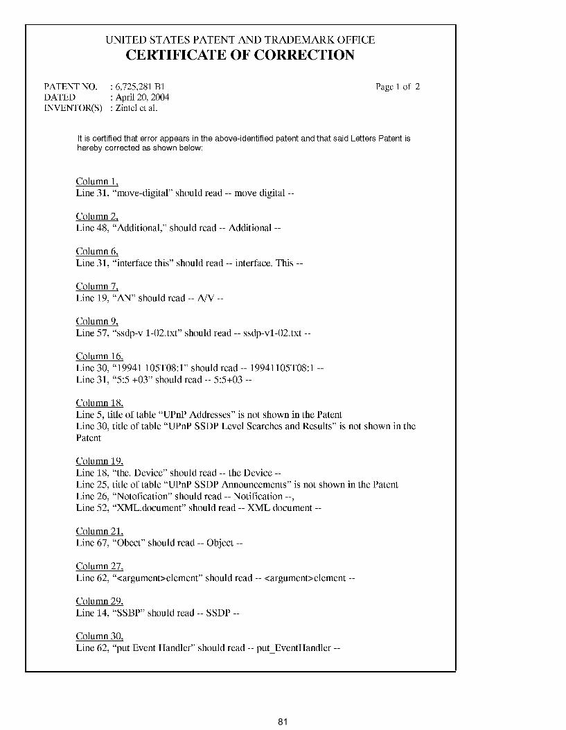
UNITED STATES PATENT AND TRADEMARK OFFICE
CERTIFICATE OF CORRECTION
PATENT NO. : 6,725,281 B1 DATED : Apri120, 2004 INVENTOR(S) : Zintel et al.
Page 1 of 2
It is certified that error appears in the above-identified patent and that said Letters Patent is hereby corrected as shown below:
Column 1, Line 31, "move-digital" should read-- move digital--
Column 2, Line 48, "Additional," should read-- Additional--
Column 6, Line 31, "interface this" should read-- interface. This --
Column 7, Line 19, "AN" should read-- NV--
Column 9, Line 57, "ssdp-v 1-02.txt" should read-- ssdp-v1-02.txt --
Column 16, Line 30, "19941105T08:1" should read-- 19941105T08:1 -Line 31, "5:5 +03" should read-- 5:5+03 --
Column 18, Line 5, title of table "UPnP Addresses" is not shown in the Patent Line 30, title of table "UPnP SSDP Level Searches and Results" is not shown in the Patent
Column 19, Line 18, "the. Device" should read -- the Device --Line 25, title of table "UPnP SSDP Announcements" is not shown in the Patent Line 26, "Notofication" should read-- Notification--, Line 52, "XML.document" should read-- XML document--
Column 21, Line 67, "Obect" should read -- Object --
Column 27, Line 62, "<argument>element" should read-- <argument>element --
Column 29, Line 14, "SSBP" should read-- SSDP --
Column 30, Line 62, "put Event Handler" should read -- put_ EventHandler --
81
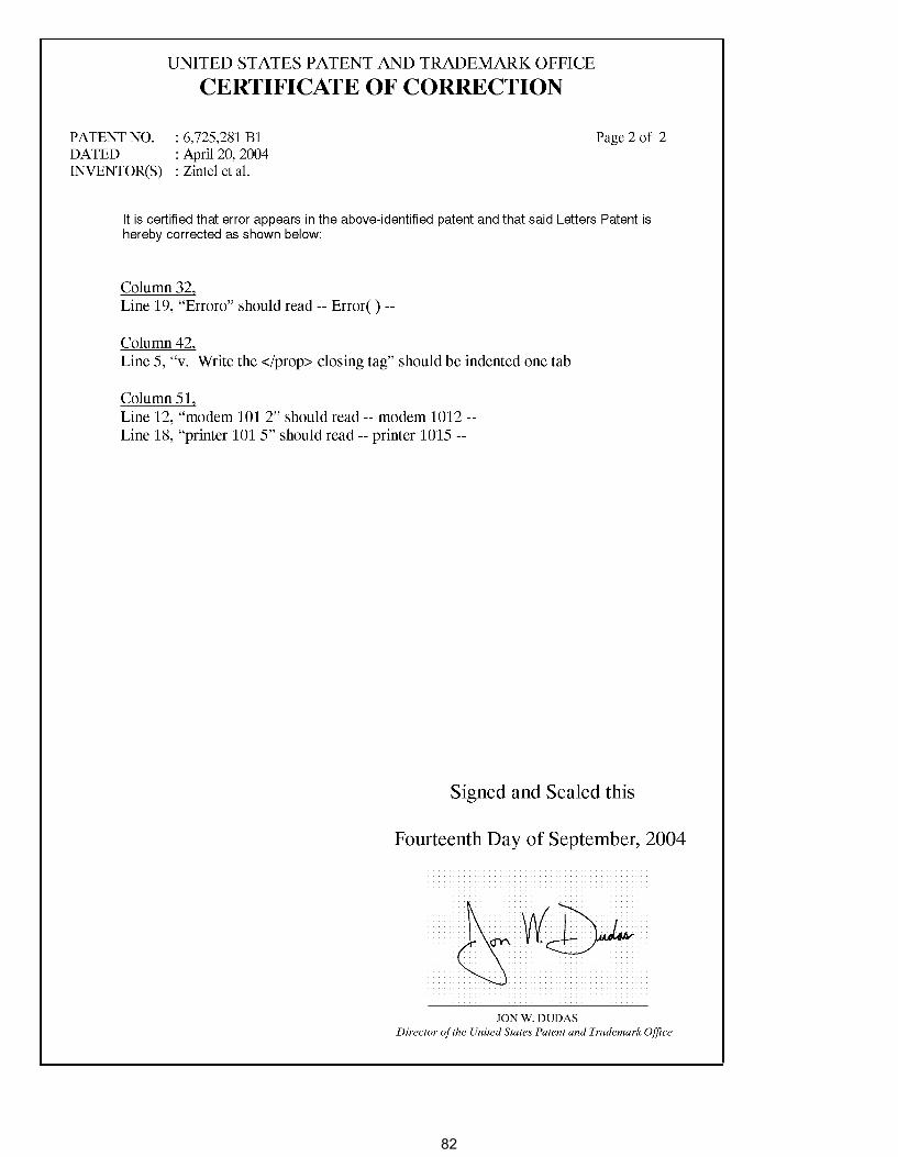
UNITED STATES PATENT AND TRADEMARK OFFICE
CERTIFICATE OF CORRECTION
PATENT NO. : 6,725,281 Bl DATED : Apri120, 2004 INVENTOR(S) : Zintel et al.
Page 2 of 2
It is certified that error appears in the above-identified patent and that said Letters Patent is hereby corrected as shown below:
Column 32, Line 19, "Erroro" should read-- Error()--
Column 42, Line 5, "v. Write the </prop> closing tag" should be indented one tab
Column 51, Line 12, "modem 101 2" should read-- modem 1012 -Line 18, "printer 101 5" should read-- printer 1015 --
Signed and Sealed this
Fourteenth Day of September, 2004
JONW.DUDAS Director of the United States Patent and Trademark Office
82
US 6,725,281 Cl 1
EXPARTE REEXAMINATION CERTIFICATE
ISSUED UNDER 35 U.S.C. 307
THE PATENT IS HEREBY AMENDED AS INDICATED BELOW.
2 puting device to effect a change in the operational state of the controlled computing device represented in the state table;
a user control point module in the user controller device operating to obtain a copy of the state table of the user controlled device and subscribe to change notifications of the state table; and
Matter enclosed in heavy brackets [ ] appeared in the patent, but has been deleted and is no longer a part of the 10
patent; matter printed in italics indicates additions made
an event source module in the controlled computing device operating according to an eventing model to distribute the change notifications to any subscribing user controller device upon a change to the state table representing
to the patent.
AS A RESULT OF REEXAMINATION, IT HAS BEEN DETERMINED THAT:
Claims 1, 2 and 20 are determined to be patentable as amended.
15
the operational state of the controlled computing device, wherein the change notifications represent the respective change in the state table, so as to thereby synchronize the user perceptible device control interface with the changed operational state among said any subscrib-
Claims 3-4, dependent on an amended claim, are 20
determined to be patentable.
ing user controller device, the state table having a plurality of entries, wherein each entry of the state table comprises at least a variable identifier, a type and a current value;
New claims 23-75 are added and determined to be patentable.
Claims 5-19, 21 and 22 were not reexamined.
1. A distributed computing network having at least one computing device, the distributed computing network com-prising:
a controlled computing device; a state table maintained by the controlled computing device
and representing an operational state of the controlled computing device;
a user controller device having user input/ output capability for presenting a user perceptible device control interface for remote user interaction with the controlled computing device to effect a change in the operational state of the controlled computing device represented in the state table;
a user control point module in the user controller device operating to obtain a copy of the state table of the user [controller] controlled device and subscribe to change notifications of the state table; and
an event source module in the controlled computing device operating according to an eventing model to distribute the change notifications to any subscribing user controller device upon a change to the state table representing the operational state of the controlled computing device, wherein the change notifications represent the respective change in the state table, so as to thereby synchronize the user perceptible device control interface with the changed operational state among said any subscribing user controller device,
25
at least one entry of the state table being of a type of data buffer, and containing a file as its current value;
whereby a change to the current value of said at least one entry effects a file transfer from the controlled device to said any subscribing user [control] controller device.
20. A peer networking state eventing and control protocol method for effecting state-concurrent multi-master control of a controlled computing device by a plurality of control point
30 computing devices communicating on a data communications network, the data communications network having the controlled computing device, a state table maintained by the controlled computing device and representing an operational state of the controlled computing device, a control point com-
35 puting device having user input/output capability for presenting a user perceptible device control interface for remote user interaction with the controlled computing device and communicating with the controlled computing device via a device control protocol to effect remote operational control of the
40 controlled computing device, a user control point module in the control point computing device operating to obtain a copy of the state table of the control point computing device and subscribe to change notifications of the state table, and an event source module operating according to an eventing
45 model to distribute [the] change notifications to any subscribing control point computing device upon a change to the operational state of the controlled computing device, so as to thereby synchronize the user perceptible device control interface with the changed operational state among said any sub-
50 scribing control point computing device, the method com-prising:
from a plurality of the control point computing devices, receiving state eventing subscription requests;
wherein the controlled computing device comprises data defining a presentation of a device control user inter- 55
face.
responsive to the state eventing subscription requests, registering subscriptions of the respective control point computing devices to state events from the controlled computing device; 2. [The distributed computing network of claim 1 further
comprising: ]A distributed computing network having at least one computing device, the distributed computing network comprising:
a controlled computing device; a state table maintained by the controlled computing
device and representing an operational state of the controlled computing device;
60
a user controller device having user input/output capabil- 65
ity for presenting a user perceptible device control interface for remote user interaction with the controlled com-
communicating state events having information descriptive of a state of the controlled computing device to the respective control point computing devices of the registered subscriptions;
receiving a control command from a control point computing device instructing the controlled computing device to perform a specified operation affecting the state of the controlled computing device;
responsive to the control command, performing the specified operation; and
83
US 6,725,281 Cl 3
communicating further state events having information descriptive of the state of the controlled computing device after the specified operation is performed to the respective control point computing devices of the registered subscriptions, whereby the plurality of control point computing devices having registered subscriptions can maintain concurrent storage of data representing the state of the controlled computing device,
wherein the controlled computing device comprises data defining a presentation of a device control user inter- lO
face. 23. A distributed computing network having at least one
computing device, the distributed computing network com-prising:
a controlled computing device; a state table maintained by the controlled computing
device and representing an operational state of the controlled computing device;
15
a user controller device having user input/output capabil- 20
ity for presenting a user perceptible device control interface for remote user interaction with the controlled computing device to effect a change in the operational state of the controlled computing device represented in the state table, the controlled computing device storing pre- 25
sentation data defining a presentation of the user perceptible device control interface;
a user control point module in the user controller device operating to obtain a copy of the state table of the user controlled device and subscribe to change notifications 30
of the state table; and an event source module in the controlled computing device
operating according to an eventing model to distribute the change notifications to any subscribing user control-
35 !er device upon a change to the state table representing the operational state of the controlled computing device, wherein the change notifications represent the respective change in the state table, so as to thereby synchronize the user perceptible device control interface with 40
the changed operational state among said any subscribing user controller device.
24. The distributed computing network of claim 23, the controlled computing device being further configured to transfer the presentation data defining the presentation of the 45
user perceptible device control interface to the user controller device.
25. The distributed computing network of claim 23, the user controller device further operating to receive the presentation data defining the presentation of the user percep- 50
tible device control interface from the controlled computing device and present the user perceptible device control interface.
4 31. The distributed computing of claim 2 3 wherein the state
table maintained by the controlled computing device represents a current logical state of the controlled computing device.
32. The distributed computing network of claim 1, the user control point module in the user controller device further operating to unsubscribe to change notifications of the state table.
33. The distributed computing network of claim 1, the controlled computing device being configured to send a copy of the state table maintained by the controlled computing device to the user control point module in the user controller device in response to receiving a subscribe message from the user control point module.
34. A distributed computing network having at least one computing device, the distributed computing network com-prising:
a controlled computing device; a state table maintained by the controlled computing
device and representing an operational state of the controlled computing device;
a user controller device having user input/output capabil-ity for presenting a user perceptible device control interface for remote user interaction with the controlled computing device to effect a change in the operational state of the controlled computing device represented in the state table;
a user control point module in the user controller device operating to obtain a copy of the state table of the user controlled device and subscribe to change notifications of the state table; and
an event source module in the controlled computing device operating according to an eventing model to distribute the change notifications to any subscribing user controller device upon a change to the state table representing the operational state of the controlled computing device, wherein the change notifications represent respective change in the state table, so as to thereby synchronize the user perceptible device control interface with the changed operational state among said any subscribing user controller device,
wherein the user control point module is configured to subscribe to change notifications of the state table by sending to the controlled computing device a subscribe message specifying timeout duration and wherein the controlled computing device is configured to remove the subscription of the user control point module in response to determining that a resubscribe message has not been received from the user control point module for at least the specified timeout duration.
35. The distributed computing network of claim 1 wherein the user control point module is configured to form an unsubscribe message and unsubscribe to change notifications of the state table by sending the unsubscribe message to the con-26. The distributed computing network of claim 2 5 wherein
the user controller device is a mobile phone. 55 trolled computing device. 2 7. The distributed computing network of claim 2 5 wherein
the user controller device is a set-top box. 2 8. The distributed computing network of claim 2 5 wherein
the user control device is a handheld computer. 29. The distributed computing network of claim 2 3 wherein 60
the state table maintained by the controlled computing device represents a current electrical state of the controlled computing device.
30. The distributed computing network of claim 2 3 wherein the state table maintained by the controlled computing device 65
represents a current mechanical state of the controlled computing device.
3 6. The distributed computing network of claim 1 wherein the controlled computing device is a cell phone.
3 7. The distributed computing network of claim 1 wherein the controlled computing device is an audio and video recorder.
3 8. The distributed computing network of claim 1 wherein the controlled computing device is an audio or video playback device.
3 9. The distributed computing network of claim 1 wherein the controlled computing device is a set-top box.
40. The distributed computing network of claim 3 9 wherein the state table represents a tuner channel selection.
84
US 6,725,281 Cl 5
41. The distributed computing network of claim 3 9 wherein the state table represents an audio decodingformat.
42. A distributed computing network having at least one computing device, the distributed computing network com-prising:
a controlled computing device; a state table maintained by the controlled computing
device and representing an operational state of the controlled computing device;
a user controller device having user input/output capabil- lO
ity for presenting a user perceptible device control interface for remote user interaction with the controlled computing device to effect a change in the operational state of the controlled computing device represented in the
15 state table;
a user control point module in the user controller device operating to obtain a copy of the state table of the user controlled device and subscribe to change notifications of the state table; and 20
an event source module in the controlled computing device according to an eventing model to distribute the change notifications to any subscribing user controller device upon a change to the state table representing the operational state of the controlled computing device, wherein 25
the change notifications represent the respective change in the state table, so as to thereby synchronize the user perceptible device control interface with the changed operational state among said any subscribing user controller device,
wherein the controlled computing device is a set-top box and wherein the state table represents a tuner channel selection, an audio decoding format, or a video decodingformat.
30
43. The distributed computing network of claim 1 wherein 35
the controlled computing device is a game console.
6 the changed operational state among said any subscribing control point computing device, the method comprising:
from a plurality of the control point computing devices, receiving state eventing subscription requests;
responsive to the state eventing subscription requests, registering subscriptions of the respective control point computing devices to state events from the controlled computing device;
communicating state events having information descriptive of a state of the controlled computing device to the respective control point computing devices of the registered subscriptions;
receiving a control command from a control point computing device instructing the controlled computing device to perform a specified operation affecting the state of the controlled computing device;
responsive to the control command, performing the specified operation;
communicating further state events having information descriptive of the state of the controlled computing device after the specified operation is performed to the respective control point computing devices of the registered subscriptions, whereby the plurality of control point computing devices having registered subscriptions can maintain concurrent storage of data representing the state of the controlled computing device;
storing presentation data defining a presentation of the user perceptible device control interface; and
transferring the presentation data defining the presentation of the user perceptible device control interface to a control point computing device.
49. The peer networking state eventing and control protocol method of claim 48 wherein at least one of the plurality of control point computing devices is a mobile phone.
50. The peer networking state eventing and control protocol method of claim 48 wherein at least one of the plurality of control point devices is a set-top box. 44. The distributed computing network of claim 1 wherein
the controlled computing device is an environment control device.
45. The distributed computing network of claim 1 wherein the user controller device is a mobile phone.
51. The peer networking state eventing and control protocol method of claim 48 wherein at least one of the plurality of
40 control point computing devices is a handheld computer.
46. The distributed computing network of claim 1 wherein the user controller device is a set-top box.
47. The distributed computing network of claim 1 wherein the user controller device is a handheld computer.
48. A peer networking state eventing and control protocol method for effecting state-concurrent multi-master control of
45
a controlled computing device by a plurality of control point computing devices communicating on a data communications network, the data communications network having the 50
controlled computing device, a state table maintained by the controlled computing device and representing an operational state of the controlled computing device, a control point computing device having user input/output capability for presenting a user perceptible device control interface for remote user 55
interaction with the controlled computing device and communicating with the controlled computing device via a device control protocol to effect remote operational control of the controlled computing device, a user control point module in the control point computing device operating to obtain a copy 60
of the state table of the control point computing device and subscribe to change notifications of the state table, and an event source module operating according to an eventing model to distribute change notifications to any subscribing control point computing device upon a change to the opera- 65
tional state of the controlled computing device, as to thereby synchronize the user perceptible device control interface with
52. The peer networking state eventing and control protocol method of claim 48 further comprising:
storing in the state table maintained by the controlled computing device a representation of a current electrical state of the controlled computing device.
53. The peer networking state eventing and control protocol method of claim 48, further comprising:
storing in the state table maintained by the controlled computing device a representation of a current mechanical state of the controlled computing device.
54. The peer networking state eventing and control protocol method of claim 48, further comprising:
storing in the state table maintained by the controlled computing device a representation of a current logical state of the controlled computing device.
55. The peer networking state eventing and control protocol method of claim 48, further comprising:
from a plurality of the control point computing devices, receiving state eventing unsubscribe requests.
56. The peer networking state eventing and control protocol method of claim 48, further comprising:
sending a copy of the state table maintained by the controlled computing device to a first user control point module in response to receiving a subscribe message from the first user control point module.
57. The peer networking state eventing and control protocol method of claim 48, further comprising:
85

US 6,725,281 Cl 7
receiving, from a first user control point module, a subscribe message specifying a timeout duration; and
removing the subscription of the first user control point module in response to determining that a re-subscribe message has not been received from the first user control point module for at least the specified timeout duration.
58. The peer networking state eventing and control protocol method of claim 48 wherein the controlled computing device is a cell phone.
59. The peer networking state eventing and control proto- 10
col method of claim 48 wherein the controlled computing device is an audio and video recorder.
60. The peer networking state eventing and control protocol method of claim 48 wherein the controlled computing device is an audio or video playback device.
61. The peer networking state eventing and control protocol method of claim 48 wherein the controlled computing device is a set-top box.
15
62. The distributed computing network of claim 61 wherein the state table represents a tuner channel selection of the 20
set-top box. 63. The distributed computing network of claim 61 wherein
the state table represents an audio decoding format of the set-top box.
64. The distributed computing network of claim 61 wherein 25
the state table represents a video decoding format of the set-top box.
8 a user control point module in the user controller device
operating to obtain a copy of the state table of the user controlled device and subscribe to change notifications of the state table; and
an event source module in the controlled computing device operating according to an eventing model to distribute the change notifications to any subscribing user controller device upon a change to the state table representing the operational state of the controlled computing device, wherein the change notifications represent the respective change in the state table, so as to thereby synchro-nize the user perceptible device control interface with the changed operational state among said any subscribing user controller device,
wherein the state table represents a tuner channel selection, an audio decoding format, or a video decoding format.
7 4. The peer networking state eventing and control protocol method of claim 20, further comprising:
storing in the state table maintained by the controlled computing device a representation of a current electrical state, a current mechanical state, or a current logical state of the controlled computing device.
7 5. A peer networking state eventing and control protocol method for effecting state-concurrent multi-master control of a controlled computing device by a plurality of control point computing devices communicating on a data communications network, the data communications network having the controlled computing device, a state table maintained by the
65. The peer networking state eventing and control protocol method of claim 48 wherein the controlled computing device is a game console.
66. The peer networking state eventing and control protocol method of claim 48 wherein the controlled computing device is an environment control device.
30 controlled computing device and representing an operational state of the controlled computing device, a control point computing device having a user input/output capability for presenting a user perceptible device control interface for remote
67. The peer network state eventing and control protocol method of claim 48 wherein at least one of the plurality of 35
control point computing devices is a mobile phone. 68. The peer networking state eventing and control proto
col method of claim 48 wherein at least one of the plurality of control point computing devices is a set-top box.
69. The peer networking state eventing and control proto- 40
col method of claim 48 wherein at least one of the plurality of control point computing devices is a handheld computer.
user interaction with the controlled computing device and communicating with the controlled computing device via a device control protocol to effect remote operational control of the controlled computing device, a user control point module in the control point computing device operating to obtain a copy of the state table of the control point computing device and subscribe to change notifications of the state table, and an event source module operating according to an eventing model to distribute change notifications to any subscribing control point computing device upon a change to the operational state of the controlled computing device, so as to
70. The distributed computing network of claim 1 wherein the state table maintained by the controlled computing device represents a current electrical state of the controlled computing device.
71. The distributed computing network of claim 1 wherein the state table maintained by the controlled computing device represents a current mechanical state of the controlled computing device.
45 thereby synchronize the user perceptible device control interface with the changed operational state among said any subscribing control point computing device, the method comprising:
72. The distributed computer network of claim 1 wherein the state table maintained by the controlled computing device represents a current logical state of the controlled computing device.
50
73. A distributed computing network having at least one 55
computing device, the distributed computing network com-prising:
a controlled computing device; a state table maintained by the controlled computing
device and representing an operational state of the con- 60
trolled computing device; a user controller device having user input/output capabil-
ity for a user perceptible device control interface for remote user interaction with the controlled computing device to effect a change in the operational state of the 65
controlled computing device represented in the state table;
from a plurality of the control point computing devices, receiving state eventing subscription requests;
responsive to the state eventing subscription requests, registering subscriptions of the respective control point computing devices to state events from the controlled computing device;
communicating state events having information descriptive of a state of the controlled computing device to the respective control point computing devices of the registered subscriptions;
receiving a control command from a control point computing device instructing the controlled computing device to perform a specified operation affecting the state of the controlled computing device;
responsive to the control command, performing the specified operation; and
communicating further state events having information descriptive of the state of the controlled computing device after the specified operation is performed to the
86
US 6,725,281 Cl 9
respective control point computing devices of the registered subscriptions, whereby the plurality of control point computing devices having registered subscriptions can maintain concurrent storage of data representing the state of the controlled computing device,
10 wherein the state table represents a tuner channel selec
tion, an audio decoding format, or a video decoding format.
* * * * *
87