Embed Size (px)
Citation preview
31
Turnouts
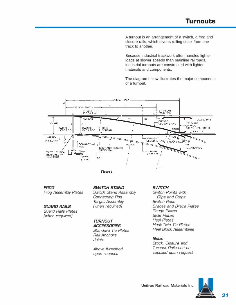
A turnout is an arrangement of a switch, a frog andclosure rails, which diverts rolling stock from onetrack to another.
Because industrial trackwork often handles lighterloads at slower speeds than mainline railroads,industrial turnouts are constructed with lighter materials and components.
The diagram below illustrates the major componentsof a turnout.
Unitrac Railroad Materials Inc.
FROGFrog Assembly Plates
GUARD RAILSGuard Rails Plates(when required)
SWITCH STANDSwitch Stand AssemblyConnecting RodTarget Assembly(when required)
TURNOUT ACCESSORIESStandard Tie PlatesRail AnchorsJoints
Above furnished upon request
SWITCH Switch Points with
Clips and Stops Switch RodsBraces and Brace PlatesGauge PlatesSlide PlatesHeel PlatesHook-Twin Tie PlatesHeel Block Assemblies
Note:Stock, Closure andTurnout Rails can be supplied upon request
32
Turnout Installation
Unitrac Railroad Materials Inc.
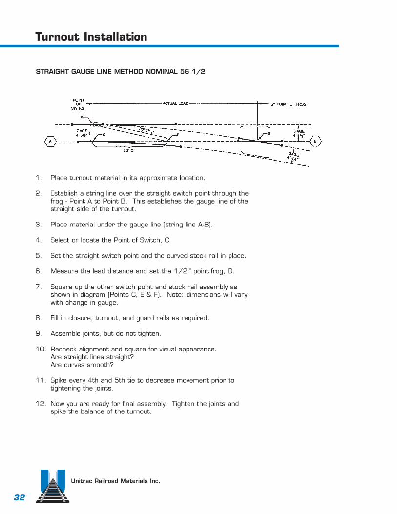
1. Place turnout material in its approximate location.
2. Establish a string line over the straight switch point through thefrog - Point A to Point B. This establishes the gauge line of thestraight side of the turnout.
3. Place material under the gauge line (string line A-B).
4. Select or locate the Point of Switch, C.
5. Set the straight switch point and the curved stock rail in place.
6. Measure the lead distance and set the 1/2’” point frog, D.
7. Square up the other switch point and stock rail assembly asshown in diagram (Points C, E & F). Note: dimensions will varywith change in gauge.
8. Fill in closure, turnout, and guard rails as required.
9. Assemble joints, but do not tighten.
10. Recheck alignment and square for visual appearance.Are straight lines straight?Are curves smooth?
11. Spike every 4th and 5th tie to decrease movement prior totightening the joints.
12. Now you are ready for final assembly. Tighten the joints andspike the balance of the turnout.
STRAIGHT GAUGE LINE METHOD NOMINAL 56 1/2
33
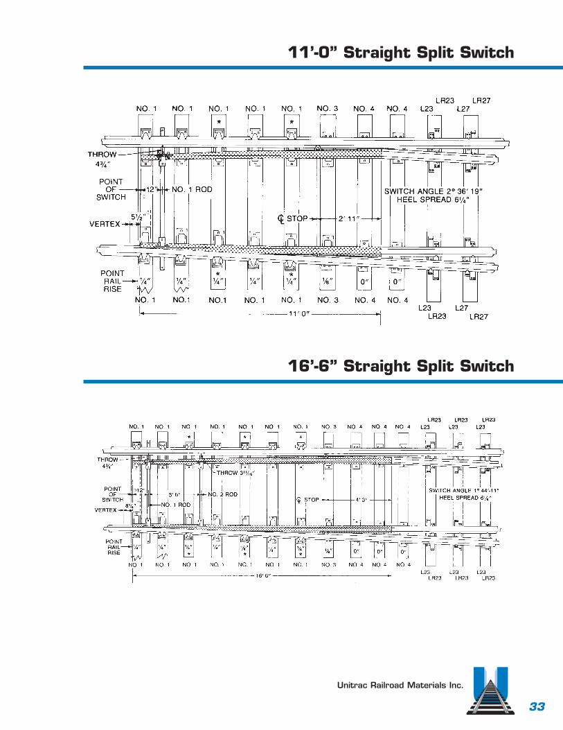
11’-0” Straight Split Switch
Unitrac Railroad Materials Inc.
16’-6” Straight Split Switch
34
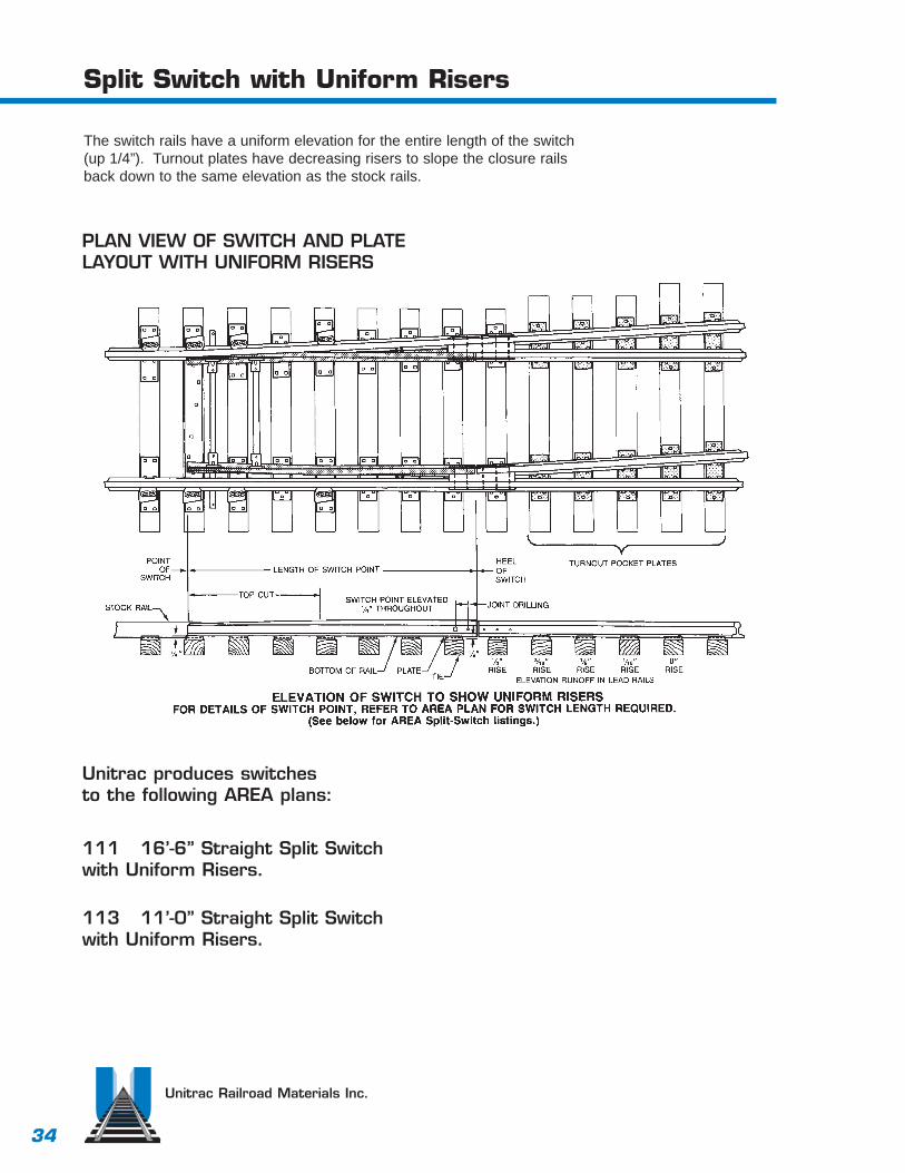
Split Switch with Uniform Risers
The switch rails have a uniform elevation for the entire length of the switch(up 1/4”). Turnout plates have decreasing risers to slope the closure railsback down to the same elevation as the stock rails.
Unitrac Railroad Materials Inc.
PLAN VIEW OF SWITCH AND PLATELAYOUT WITH UNIFORM RISERS
Unitrac produces switches to the following AREA plans:
111 16’-6” Straight Split Switch with Uniform Risers.
113 11’-0” Straight Split Switch with Uniform Risers.

35
Split Switch with Graduated Risers
The switch rails are elevated to the required height above the stock rail(up 1/4”), then gradually slope down to 0” at the heel of the switch.Hook twin turnout plates are used.
Unitrac Railroad Materials Inc.
PLAN VIEW OF SWITCH AND PLATELAYOUT WITH GRADUATED RISERS
Unitrac produces switches to the following AREA plans:
112 16’-6” Straight Split Switch with Graduated Risers.
114 11’-0” Straight Split Switch with Graduated Risers.
36
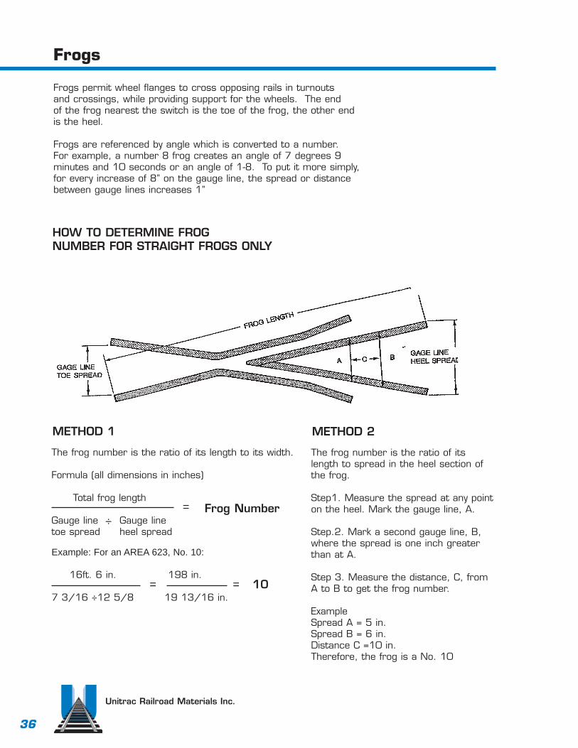
Frogs
Frogs permit wheel flanges to cross opposing rails in turnouts and crossings, while providing support for the wheels. The end of the frog nearest the switch is the toe of the frog, the other end is the heel.
Frogs are referenced by angle which is converted to a number.For example, a number 8 frog creates an angle of 7 degrees 9 minutes and 10 seconds or an angle of 1-8. To put it more simply,for every increase of 8” on the gauge line, the spread or distancebetween gauge lines increases 1”
Unitrac Railroad Materials Inc.
HOW TO DETERMINE FROGNUMBER FOR STRAIGHT FROGS ONLY
METHOD 1
The frog number is the ratio of its length to its width.
Formula (all dimensions in inches)
Total frog length
Gauge line Gauge line toe spread heel spread
Example: For an AREA 623, No. 10:
16ft. 6 in. 198 in.
7 3/16 ÷12 5/8 19 13/16 in.
÷= Frog Number
= 10=
METHOD 2
The frog number is the ratio of itslength to spread in the heel section ofthe frog.
Step1. Measure the spread at any pointon the heel. Mark the gauge line, A.
Step.2. Mark a second gauge line, B,where the spread is one inch greater than at A.
Step 3. Measure the distance, C, fromA to B to get the frog number.
ExampleSpread A = 5 in.Spread B = 6 in.Distance C =10 in.Therefore, the frog is a No. 10
37
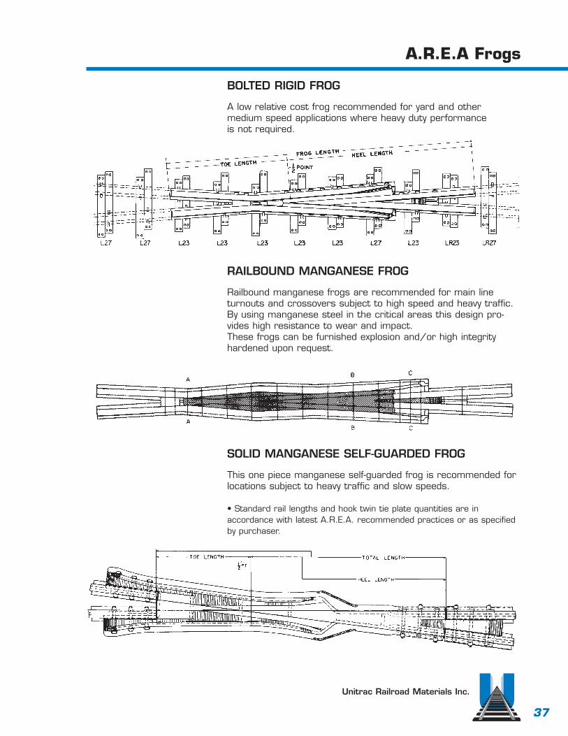
A.R.E.A Frogs
Unitrac Railroad Materials Inc.
BOLTED RIGID FROG
A low relative cost frog recommended for yard and other medium speed applications where heavy duty performance is not required.
RAILBOUND MANGANESE FROG
Railbound manganese frogs are recommended for main lineturnouts and crossovers subject to high speed and heavy traffic.By using manganese steel in the critical areas this design pro-vides high resistance to wear and impact.These frogs can be furnished explosion and/or high integrityhardened upon request.
SOLID MANGANESE SELF-GUARDED FROG
This one piece manganese self-guarded frog is recommended forlocations subject to heavy traffic and slow speeds.
• Standard rail lengths and hook twin tie plate quantities are in accordance with latest A.R.E.A. recommended practices or as specifiedby purchaser.

38
Hook Twin Tie Plates for Frogs
TYPICAL APPLICATIONS OF HOOK-TWIN TIEPLATES. Refer to AREA frog plans for requiredquantities of plates.
Frog design, frog size and type of connectingrails will determine the quantity of hook-twin tieplates required. Connecting rail types are listedat right.
Unitrac Railroad Materials Inc.
TYPE I Rail - Rails having base up to 5 3/16” and head 2 9/16” inclusive
TYPE II Rail - Rails having base up to 5 1/2” and head 2 3/4” inclusive
TYPE III Rail - Rails having base up to 6” and head 3” inclusive
39
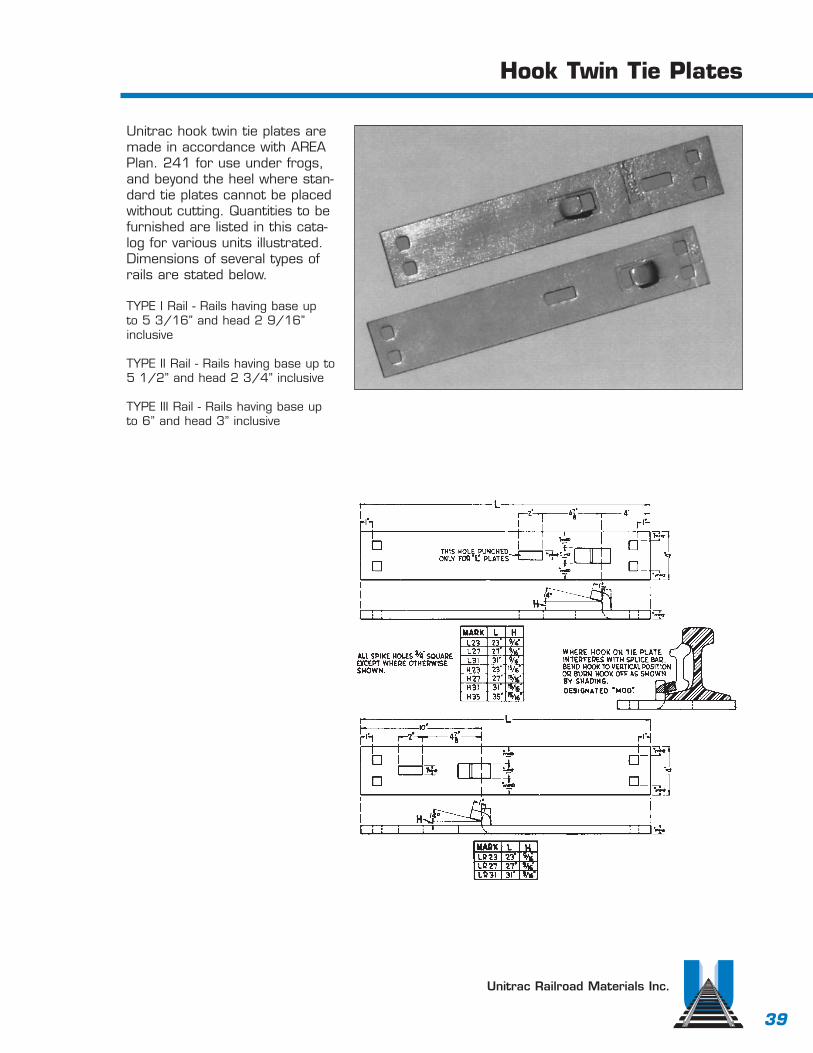
Hook Twin Tie Plates
Unitrac Railroad Materials Inc.
Unitrac hook twin tie plates aremade in accordance with AREAPlan. 241 for use under frogs,and beyond the heel where stan-dard tie plates cannot be placedwithout cutting. Quantities to befurnished are listed in this cata-log for various units illustrated.Dimensions of several types ofrails are stated below.
TYPE I Rail - Rails having base up to 5 3/16” and head 2 9/16”inclusive
TYPE II Rail - Rails having base up to 5 1/2” and head 2 3/4” inclusive
TYPE III Rail - Rails having base upto 6” and head 3” inclusive
40
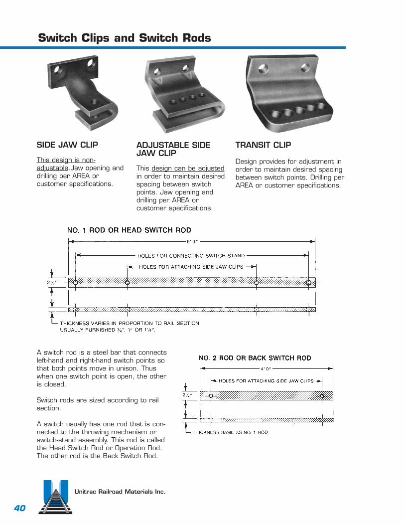
Switch Clips and Switch Rods
Unitrac Railroad Materials Inc.
SIDE JAW CLIP
This design is non-adjustable.Jaw opening anddrilling per AREA or customer specifications.
ADJUSTABLE SIDEJAW CLIP
This design can be adjustedin order to maintain desiredspacing between switchpoints. Jaw opening anddrilling per AREA or customer specifications.
TRANSIT CLIP
Design provides for adjustment inorder to maintain desired spacingbetween switch points. Drilling perAREA or customer specifications.
A switch rod is a steel bar that connectsleft-hand and right-hand switch points sothat both points move in unison. Thuswhen one switch point is open, the otheris closed.
Switch rods are sized according to railsection.
A switch usually has one rod that is con-nected to the throwing mechanism orswitch-stand assembly. This rod is calledthe Head Switch Rod or Operation Rod.The other rod is the Back Switch Rod.
41
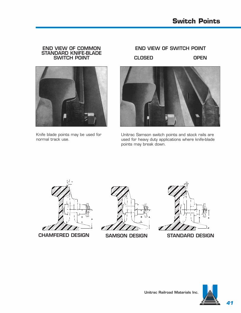
Switch Points
Unitrac Railroad Materials Inc.
Unitrac Samson switch points and stock rails areused for heavy duty applications where knife-bladepoints may break down.
END VIEW OF SWITCH POINT
CLOSED OPEN
END VIEW OF COMMONSTANDARD KNIFE-BLADE
SWITCH POINT
CHAMFERED DESIGN SAMSON DESIGN STANDARD DESIGN
Knife blade points may be used fornormal track use.
42
Heel Blocks
Unitrac Railroad Materials Inc.
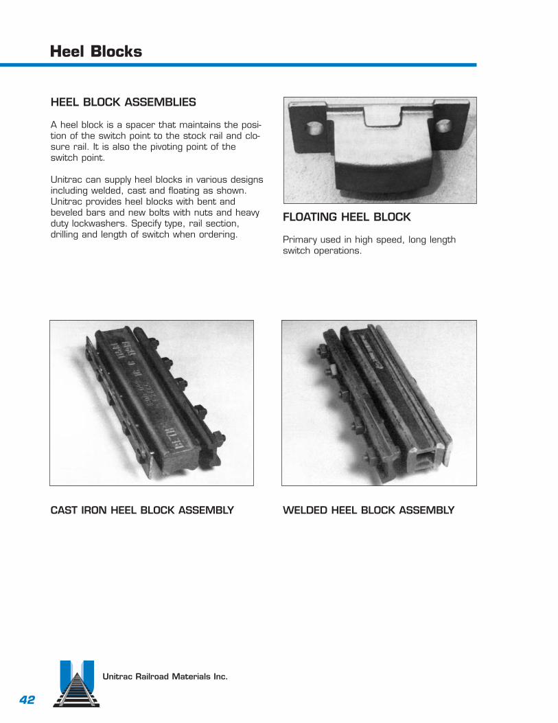
HEEL BLOCK ASSEMBLIES
A heel block is a spacer that maintains the posi-tion of the switch point to the stock rail and clo-sure rail. It is also the pivoting point of theswitch point.
Unitrac can supply heel blocks in various designsincluding welded, cast and floating as shown.Unitrac provides heel blocks with bent andbeveled bars and new bolts with nuts and heavyduty lockwashers. Specify type, rail section,drilling and length of switch when ordering.
FLOATING HEEL BLOCK
Primary used in high speed, long lengthswitch operations.
WELDED HEEL BLOCK ASSEMBLYCAST IRON HEEL BLOCK ASSEMBLY

43
Unitrac Railroad Materials Inc.
Braces are designed to restrain movement of thestock rail when a switch is opened or closed.Unitrac can furnish forged steel rigid braces similarto AREA Plan 223. We can furnish a number ofadjustable brace designs that will fill your mostcommon or unusual requirements. (Available in the811 design or the AREA Plan 224 Type A designas shown below.) Also available is BethlehamSureFit Boltless Adjustable Brace. Available in bothnew and relay, all braces are checked with railprior to shipping to insure a correct fit.
Switch Plates and Braces
Bethleham SureFit Boltless Adjustable Brace
Area Design 224Type A Adjustable Brace
Design 8-11Adjustable Brace
Forged Rigid BracePer Area 223
44
Unitrac Railroad Materials Inc.
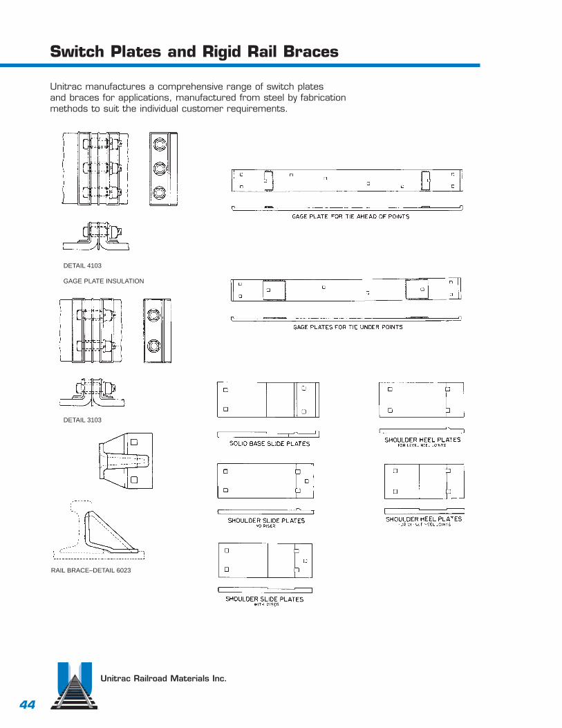
Switch Plates and Rigid Rail Braces
Unitrac manufactures a comprehensive range of switch plates and braces for applications, manufactured from steel by fabricationmethods to suit the individual customer requirements.
DETAIL 4103
GAGE PLATE INSULATION
DETAIL 3103
RAIL BRACE–DETAIL 6023
45
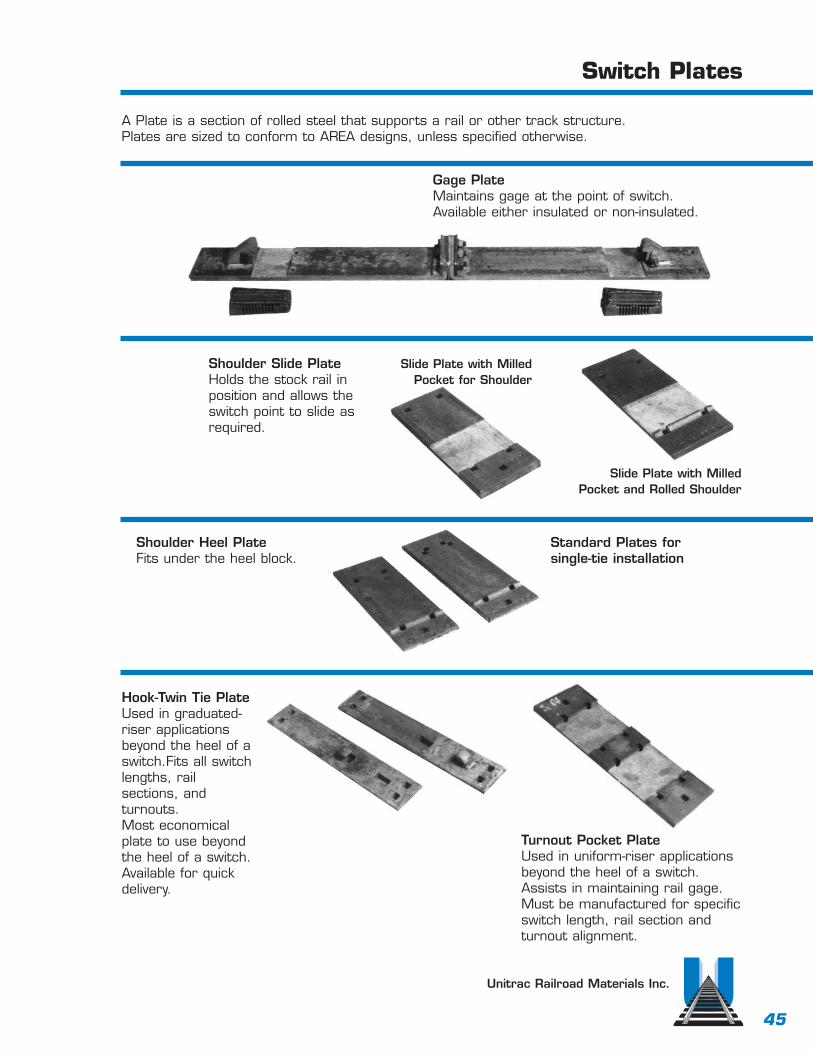
Switch Plates
Unitrac Railroad Materials Inc.
Gage PlateMaintains gage at the point of switch.Available either insulated or non-insulated.
Shoulder Slide PlateHolds the stock rail inposition and allows theswitch point to slide asrequired.
Slide Plate with Milled Pocket for Shoulder
Slide Plate with Milled Pocket and Rolled Shoulder
Shoulder Heel PlateFits under the heel block.
Standard Plates forsingle-tie installation
Hook-Twin Tie PlateUsed in graduated-riser applicationsbeyond the heel of aswitch.Fits all switchlengths, rail sections, andturnouts.Most economicalplate to use beyondthe heel of a switch.Available for quickdelivery.
Turnout Pocket PlateUsed in uniform-riser applicationsbeyond the heel of a switch. Assists in maintaining rail gage. Must be manufactured for specificswitch length, rail section andturnout alignment.
A Plate is a section of rolled steel that supports a rail or other track structure. Plates are sized to conform to AREA designs, unless specified otherwise.
46
Guard Rails
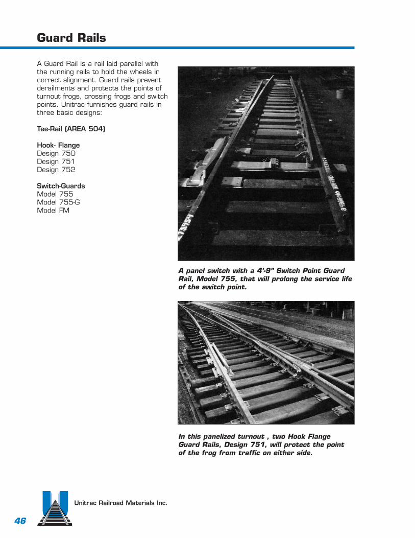
A Guard Rail is a rail laid parallel withthe running rails to hold the wheels incorrect alignment. Guard rails preventderailments and protects the points ofturnout frogs, crossing frogs and switchpoints. Unitrac furnishes guard rails inthree basic designs:
Tee-Rail (AREA 504)
Hook- FlangeDesign 750Design 751Design 752
Switch-GuardsModel 755Model 755-GModel FM
Unitrac Railroad Materials Inc.
A panel switch with a 4’-9” Switch Point GuardRail, Model 755, that will prolong the service lifeof the switch point.
In this panelized turnout , two Hook FlangeGuard Rails, Design 751, will protect the pointof the frog from traffic on either side.
47
A.R.E.A. Guard Rails
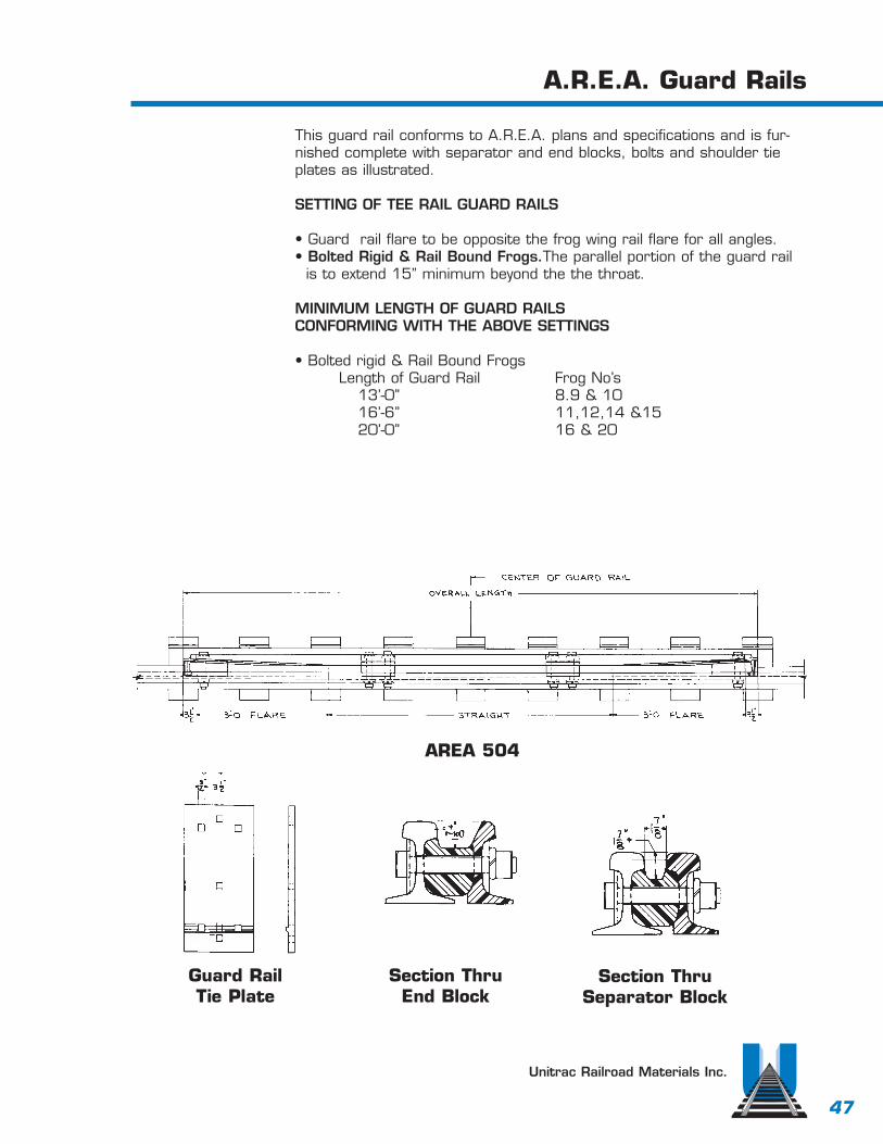
This guard rail conforms to A.R.E.A. plans and specifications and is fur-nished complete with separator and end blocks, bolts and shoulder tieplates as illustrated.
SETTING OF TEE RAIL GUARD RAILS
• Guard rail flare to be opposite the frog wing rail flare for all angles.• Bolted Rigid & Rail Bound Frogs.The parallel portion of the guard rail
is to extend 15” minimum beyond the the throat.
MINIMUM LENGTH OF GUARD RAILS CONFORMING WITH THE ABOVE SETTINGS
• Bolted rigid & Rail Bound FrogsLength of Guard Rail Frog No’s
13’-0” 8.9 & 1016’-6” 11,12,14 &1520’-0” 16 & 20
Unitrac Railroad Materials Inc.
AREA 504
Guard Rail Tie Plate
Section ThruSeparator Block
Section Thru End Block
48
Hook Flange Guard Rails
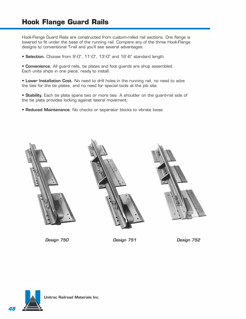
Hook-Flange Guard Rails are constructed from custom-rolled rail sections. One flange islowered to fit under the base of the running rail. Compare any of the three Hook-Flangedesigns to conventional T-rail and you’ll see several advantages:
• Selection. Choose from 9’-0”, 11’-0”, 13’-0” and 16’-6” standard length.
• Convenience. All guard rails, tie plates and foot guards are shop assembled. Each units ships in one piece, ready to install.
• Lower Installation Cost. No need to drill holes in the running rail, no need to adzethe ties for the tie plates, and no need for special tools at the job site.
• Stability. Each tie plate spans two or more ties. A shoulder on the guard-rail side ofthe tie plate provides locking against lateral movement.
• Reduced Maintenance. No checks or separator blocks to vibrate loose.
Unitrac Railroad Materials Inc.
Design 750 Design 751 Design 752

49
Switch-Point Guard Rails
Switch-Point Guard Rails protect the switch point, prolong the life ofstock rails, reduce flange cutting, prevent wheel climbing, and help toprevent derailments at the switch.
The guard rail is heat treated for extra long life.
Guard rail, plates, braces and filler blocks are shipped assembled,ready for installation.
No special tools are required at the job site.Switch-Point Guard Rails are practically free of maintenance expense.
Unitrac Railroad Materials Inc.
Model 755-GFurnished with gage plate
Model FM
Model 755 Switch-Point Guard Rail

50
Switch Point Derail
A switch point derail will derail rolling stock in anemergency. Some useful locations may be a sidingleading into a chemical loading area, or if anuncontrolled car can get from a side track onto amain track. Available in 11’ single (as shown below)or in 16’6”. Both are available as a double switchpoint derail. Unitrac can provide these in new, or fullyreconditioned, complete per your bill of materials.
HOW TO ORDERPlease specify (in addition to the usual switch information):
1. Whether switch point is left-hand or right-hand.
2. If stock rail is required, include:a. Length. b. Stagger. c. Joint drilling.
TYPICAL LAYOUT11’0” SWITCH FOR RIGHT-HAND TURNOUT FOR ILLUSTRATION ONLY. CAN BE FURNISHED TO CUSTOMER’S DESIRED LENGTH, ALIGNMENT AND ACCESSORIES.
Unitrac Railroad Materials Inc.