Embed Size (px)
Citation preview
General Description Manual
NDA-31581ISSUE 2.0
SV9100®

NEC Corporation of America reserves the right to change the specifications, functions, or features at anytime without notice.
NEC Corporation of America has prepared this document for use by its employees and customers. Theinformation contained herein is the property of NEC Corporation of America and shall not be reproducedwithout prior written approval of NEC Corporation of America.
Dterm, NEAX and UNIVERGE are registered trademarks of NEC Corporation and Electra Elite is aregistered trademark of NEC America, Inc. Windows, Outlook and Internet Explorer are registeredtrademarks of Microsoft Corporation. AT&T, the AT&T logo and all other AT&T marks are trademarks ofAT&T Intellectual Property and/or AT&T affiliated companies. Lucent Technologies is a trademark orservice mark of Lucent Technologies Inc. Nortel Networks and the Nortel Networks logo are trademarksof Nortel Networks. Verizon Wireless is a trademark of Verizon Trademark Services, LLC. Pentium is atrademark or registered trademark of Intel Corporation or its subsidiaries in the United States and othercountries. ViewCall and ViewMail are registered trademarks of Active Voice, LLC. Adobe, Flash andReader are registered trademarks of Adobe Systems, Incorporated in the United States and/or othercountries. The Google Chrome browser is a trademark of Google Inc. Mozilla and Firefox are registeredtrademarks of the Mozilla Foundation. SonicView is a trademark of TriVium Systems, Inc. iPhone is aregistered trademark of Apple Inc. App StoreSM is a service mark of Apple Inc. Safari is a trademark ofApple Inc., registered in the U.S. and other countries. Salesforce.com is a registered trademark ofSalesforce.com, inc. Tigerpaw is a registered trademark of Tigerpaw Software, Inc. Plantronics andSavi are registered trademarks of Plantronics, Inc. AMD Athlon and AMD Duron are trademarks ofAdvanced Micro Devices, Inc. Wi-Fi is a registered trademark of Wi-Fi Alliance.
Copyright 2015
NEC Corporation of America6535 N. State Highway 161
Irving, TX 75039-2402
Communications Technology Group

General Information
The UNIVERGE SV9100 system is a feature-rich key system that provides over 12000 features including Computer Telephony Integration, Contact Center, Uniform Call Distribution, ISDN-BRI Voice Trunks, ISDN-PRI Voice Trunks, IP Telephony, Voice over Internet Protocol (VoIP) trunks and stations, and many others.
The UNIVERGE SV9100 system provides what the customer needs today and, as business expands, the system can be expanded to grow as well.
The UNIVERGE SV9100 system has a set of manuals that provide all the information necessary to install and support the system. The manuals are described in this preface.
This Manual
This manual provides general information about the system, its features, system configuration, and standards. This manual provides an overview of the UNIVERGE SV9100 system and is useful when presenting information to potential customers.
Chapter 1 – Introduction
This chapter provides an overview and a brief description of the system.
Chapter 2 – Features
This chapter provides a list of features that are available with the system. Each feature is briefly described.
Chapter 3 – Equipment
This chapter provides a list and brief description of the equipment that is available with the system.
Chapter 4 – Installation, Programming, and Maintenance Overview
This chapter briefly describes the installation, programming functions, and maintenance of the system.
Chapter 5 – Hardware Specifications
This chapter provides requirements and specifications relating to the system hardware. This chapter is helpful to those that install the system.
Preface
Supporting Documents
UNIVERGE SV9100 Features and Specifications Manual
This manual provides detailed information concerning every feature available in the system.
UNIVERGE SV9100 System Hardware Manual
The System Hardware Manual is provided for the system installer. This manual has detailed instructions for installing the UNIVERGE SV9100 chassis, blades, multiline terminals, and optional equipment.
UNIVERGE SV9100 Programming Manual
This manual provides instructions for programming the UNIVERGE SV9100 system using a multiline terminal or PC.
UNIVERGE SV9100 PC Programming Manual
This manual describes the operation of the PCPro program for the UNIVERGE SV9100 system. This program is a user-friendly Windows® application that allows the user to program and configure features of the UNIVERGE SV9100 system from the PC environment.
General Description Manual R-1
GENERAL INFORMATION
This equipment complies with Part 68 of the FCC Rules and the requirements adopted by the ACTA. On the equipment is a label that contains, among other information, a product identifier in the format:US:AAAEQ##TXXXX. If requested, this number must be provided to the telephone company.
The telephone company may change its technical operations and procedures. When such changes affect the compatibility or use of the UNIVERGE SV9100 system, the telephone company is required to give adequate notice of the changes for you to maintain uninterrupted service.
The REN is used to determine the number of devices that may be connected to a telephone line. Excessive RENs on a telephone line may result in the devices not ringing in response to an incoming call. In most, but not all areas, the sum of RENs should not exceed five (5.0). To be certain of the number of devices that may be connected to a line, as determined by the total RENs, contact the local telephone company. For products approved after July 23, 2001, the REN for this product is the product identifier in format: US:AAAEQ##TXXXX. The digits represented by ## are the REN without a decimal point (e.g., 03 is a REN of 0.3).
Connection to party line service is subject to state tariffs. Contact the state public utilities commission, public service commission or corporation commission for information.
For single and two-line equipment that connects to the telephone network via a plug and jack, the plug and jack used with this equipment must comply with FCC Part 68 rules.
A plug and jack used to connect this equipment to the premises wiring and telephone network must comply with the applicable FCC Part 68 rules and requirements adopted by the ACTA. A compliant telephone cord and modular plug is provided with this product. It must be connected to a compatible modular jack that is also compliant.
TELEPHONE/SERVICE PROVIDER COMPANY NOTIFICATION
Before connecting this telephone system to the telephone network, the following information must be provided to the telephone company:
Your telephone number.
FCC registration number:
When the SV9100 system is to be installed as a Key Function system (no dial access to Trunk Groups/Route Advance Blocks), use the following number:
US:NIFKF07BSN1750
Regulatory
Issue 2.0
R-2
When the SV9100 system is to be installed as a Multifunction system, use the following number:
US:NIFMF07BSN1750
When the SV9100 system is to be installed as a PBX system, use the following number:
US:NIFPF07BSN1750
Ringer Equivalence Number (REN): 0.7B
USOC jacks required: RJ11C, RJEX, RJ2FX, RJ2HX, RJ48C, RJ21X
INCIDENCE OF HARM
If this equipment causes harm to the telephone network, the telephone company will notify you in advance that temporary discontinuance of service may be required. But if advance notice is not practical, the telephone company will notify the customer as soon as possible. Also, you will be advised of your right to file a complaint with the FCC if you believe it is necessary.
The telephone company may change its facilities, equipment, operations or procedures that could affect the operation of the equipment. If this happens, the telephone company will provide advance notice for you to make necessary modifications to maintain interrupted service.
REPAIR SERVICE REQUIREMENTS
If the equipment is causing harm to the telephone network, the telephone company may request that you disconnect the equipment until the problem is resolved.
If equipment malfunctions, all repairs must be performed by an authorized agent of NEC Corporation of America. The user requiring service is responsible for reporting the need for service to an NEC Corporation of America authorized agent or to NEC Corporation of America.
PRIVATE (LEASED) LINES
For Private (Leased) Line (Analog Data Format) equipment, type JM8 jack is required. Refer to ATIS Technical Report No. 5 for details on this connector.
The Facility Interface Code (FIC) associated with each private line application represents the type of service that is provided by the telephone company. The user instructions must contain a detailed list of private line ports and the associated FICs for which the equipment has been approved. In addition, the Service Order Code (SOC) must also be included for analog systems. The SOC indicates the degree of network protection provided by the equipment.
Issue 2.0
General Description Manual R-3
For Private (Leased) Line (Digital Format) equipment, in addition to the general requirements for all equipment, certain digital connections require that an encoded analog content and billing protection affidavit be provided the telephone company. Customer instructions must contain information on the preparation and submission of the affidavit.
To comply with state tariffs, the telephone company must be given notification prior to connection. In some states, the state public utility commission, public service commission or corporation commission must give prior approval of connection.
TOLL RESTRICTION AND LEAST COST ROUTING EQUIPMENT
The consumer/purchaser/supplier instructions accompanying this equipment and/or software features must contain the following notice:
The software contained in the UNIVERGE SV9100 to allow user access to the network must be upgraded to recognize newly established network area codes and exchange codes as they are placed into service.
Failure to upgrade the premises systems or peripheral equipment to recognize the new codes as they are established will restrict the customer and the customer’s employees from gaining access to the network and these codes.
DIRECT INWARD DIALING
ALLOWING THIS EQUIPMENT TO BE OPERATED IN SUCH A MANNER AS TO NOT PROVIDE FOR PROPER ANSWER SUPERVISION IS A VIOLATION OF PART 68 OF THE FCC RULES.
Direct Inward Dialing (DID) must contain the following:
Proper Answer Supervision is when:
This equipment returns answer supervision to the Public Switched Telephone Network (PSTN) when Direct Inward Dialing (DID) calls are:
Answered by the called station.
Answered by the Attendant.
Routed to a recorded announcement that can be administered by the Customer Premise Equipment (CPE) user.
Routed to a dial prompt.
This equipment returns answer supervision on all DID calls forwarded to the Public Switched Telephone Network (PSTN). Permissible exceptions are:
A call is unanswered.
A busy tone is received.
A reorder tone is received.
Issue 2.0
R-4
VOICE ANNOUNCEMENT/MONITORING OVER DID LINES
When using voice announcement or monitoring over DID Lines, observe the following.
EQUAL ACCESS REQUIREMENTS
If equipment such as Private Branch Exchanges (PBX), key systems or customer-owned coin/credit card telephones is sold to a call aggregator, it must be able to provide users access to interstate providers of operator services through the use of access codes. Modification of this equipment by call aggregators to block access dialing codes is a violation of the Telephone Operator Consumers Act of 1990.
ELECTRICAL SAFETY ADVISORY
Parties responsible for equipment requiring AC power should consider including an advisory notice in their customer information suggesting the customer use a surge arrestor. Telephone companies report that electrical surges, typically lightening transients, are very destructive to customer terminal equipment connected to AC power sources. This has been identified as a major nationwide problem.
HEARING AID COMPATIBILITY
NEC Multiline Terminals and NEC Single Line Telephones that are provided for this system are hearing aid compatible. The manufacturer of other Single Line Telephones for use with the system must provide notice of hearing aid compatibility to comply with FCC rules that now prohibit the use of non-hearing aid compatible telephones.
CAUTION
Using the Voice Announcement feature to eavesdrop or record sound activities at the other end of the telephone line may be illegal under certain circumstances and laws. Consult a legal advisor before implementing any practice to monitor or record a telephone conversation. Some federal and state laws require a party monitoring or recording a telephone to use a beep-tone(s), notify all parties to the telephone conversation and/or obtain consent of all parties to the telephone conversation. In monitoring or recording sound activities at the other end of the telephone line using the Voice Announcement feature, the sound of the alert tone at the beginning of the Voice Announcement may or may not be considered sufficient under applicable laws. Some of the applicable laws provide for strict penalties for illegal monitoring or recording of telephone conversations.
Issue 2.0
General Description Manual R-5
MUSIC ON HOLD
RADIO FREQUENCY INTERFERENCE
In compliance with FCC Part 15 rules, the following statement is provided:
SAFETY INFORMATION
This equipment has been certified by Canadian Standards Association and found to comply with all applicable requirements:
CAN/CSA C22.2 No. 0-M – General Requirements – Canadian Electrical Code, Part II
CAN/CSA C22.2 No. 60950-1-07 – Safety of Information Technology Equipment – Part l: General Requirements
UL 60950-1-SAFETY, 2nd Edition – Safety of Information Technology Equipment – Part I: General Requirements
CAUTION
"In accordance with U.S. Copyright Law, a license may be required from the American Society of Composers, Authors and Publishers, or other similar organization, if radio or TV broadcasts are transmitted through the Music On Hold feature of this telecommunication system. NEC Corporation of America hereby disclaims any liability arising out of the failure to obtain such a license."
CAUTION
“This equipment generates, uses, and can radiate radio frequency energy and if not installed and used in accordance with the System Hardware Manual, may cause interference to radio communications. This equipment has been tested and approved for compliance with the limits for a Class A computing device pursuant to subpart J of Part 15 of FCC Rules, that are designed to provide reasonable protection against such interference when operated in a commercial environment. Operation of this telephone system in a residential area is likely to cause interference, in which case, the user, at his or her own expense, is required to take whatever measures may be required to correct the interference.”
Issue 2.0
R-6
INDUSTRY CANADA REQUIREMENTS
Industry Canada has established rules that permit this telephone system to be directly connected to the telephone network. Prior to the connection or disconnection of this telephone system to or from the telephone network, the telephone company must be provided with the following information.
This product meets the applicable Industry Canada Technical Specifications/Le present material est conforme aux specifications techniques applicables d’industrie Canada.
1. Your telephone number.
2. IC registration number: IC: 140L-SN1750
3. Ringer Equivalence Number (REN) of the equipment: 0.7
Before installing this equipment, users should ensure that it is permissible to be connected to the facilities of the local telecommunications company. The equipment must also be installed using an acceptable method of connection. The customer should be aware that compliance with the above conditions may not prevent degradation of service in some situations.
Repairs to certified equipment should be coordinated by a representative designated by the supplier. Any repairs or alterations made by the user to this equipment, or equipment malfunctions, may give the telecommunications company cause to request the user to disconnect the equipment.
Users should ensure for their own protection that the electrical ground connections of the power utility, telephone lines and internal metallic water pipe system, when present, are connected together. This precaution may be particularly important in rural areas.
The Ringer Equivalence Number (REN) is an indication of the maximum number of devices allowed to be connected to the telephone interface. The termination on an interface may consist of any combination of devices subject only to the requirement that the sum of RENs of all the devices does not exceed five/L’indice d’equivalence de la sonnerie (IES) sert a indiquer le nombre maximal de terminaus qui peuvent etre raccordes a une interface telephonique. La terminaison d’une interface peut consister en une combinaison quelconque de dispositifs, a la seule condition que la somme d’indices d’equivalence de la sonnerie de tous les dispositifs n’excede pas 5.
This equipment has been certified by the Canadian Standards Association and found to comply with all applicable requirements of the standard for telephone equipment C 22.2 No. 225.
This equipment meets IC requirements CS03, PART II, PART III, PART VI.
This digital apparatus does not exceed the Class A limits for radio noise emissions from digital apparatus as set out in the radio interference regulations of Industry Canada/Le present appareil numerique n’emet pas de bruits radioelectriques depassant les limites applicables aux appareils numeriques de Classe A prescrites dans le reglement sur le brouillage radioelectrique edicte par Industrie Canada.
CAUTION
Users should not attempt to make such connections themselves, but should contact the applicable electrical inspection authority or electrician.
Issue 2.0
General Description Manual R-7
BATTERY DISPOSAL
The UNIVERGE SV9100 system includes the batteries listed below. When disposing of these batteries, you must comply with applicable federal and state regulations regarding proper disposal procedures.
The SV9100 GCD-CP10 provides memory backup for approximately three years. The Lithium battery should be replaced every two years.
IMPORTANT SAFEGUARDS FOR BATTERY DISPOSAL
DO NOT PLACE USED BATTERIES IN YOUR REGULAR TRASH! THE PRODUCT YOU PURCHASED CONTAINS LITHIUM, NICKEL-CADMIUM OR SEALED LEAD BATTERIES. LITHIUM, NICKEL-CADMIUM OR SEALED LEAD BATTERIES MUST BE COLLECTED, RECYCLED, OR DISPOSED OF IN AN ENVIRONMENTALLY SOUND MANNER.
The incineration, landfilling or mixing of nickel-cadmium or sealed lead batteries with the municipal solid waste stream is PROHIBITED BY LAW in most areas. Contact your local solid waste management officials for other information regarding the environmentally sound collection, recycling, and disposal of the battery.
Nickel-Cadmium (or sealed lead) batteries must be returned to a federal or state approved nickel-cadmium (or sealed lead) battery recycler. This may be where the batteries were originally sold or a local seller of automotive batteries. Contact your local waste management officials for other information regarding the environmentally sound collection, recycling and disposal of the battery contained in this product. For Ni-Cd batteries, you can also call 1-800-8-BATTERYSM when further information is required.
The packaging for the UNIVERGE SV9100 system contains the following labels regarding proper disposal.
Table R-1 Battery Types and Quantities for Chassis and Blades
Unit Name Type of Battery Quantity
GCD-CP10 Lithium 1
DTL-8R-1 Ni MH 1
CHS LARGE BATT SET Sealed Lead 6
Headset Cordless II Ni MH 1
Internal Batteries Sealed Lead 2
BCH-L Lithium-ion 1
G955 Wireless Lithium-ion 1
CHS2UG B SMALL BATT SET Sealed Lead 2
Issue 2.0
R-8
PRODUCT PACKAGE LABELING
EUROPEAN UNION INFORMATION
Notice to the user
The system described in this manual is intended to be connected to analog and digital networks and supports a wide range of peripheral equipment. The following interfaces are available for connection to public analog and digital telecommunication networks:
TBR3 ISDN basic rate interface
TBR4 ISDN primary rate interface
ES203-021 Analogue interface
To take advantage of all features of this system and the connected equipment, the country or network specific features should match the supported features of the system. For an overview of the supported features, refer to the documentation that comes with this system, or contact your local NEC representative.
CONTAINS NICKEL-CADMIUM BATTERY. BATTERY MUST BE RECYCLED OR DISPOSED OF PROPERLY. MUST NOT BE DISPOSED OF IN MUNICIPAL WASTE.
CONTAINS SEALED LEAD BATTERY. BATTERY MUST BE RECYCLED. MUST NOT BE DISPOSED OF IN MUNICIPAL WASTE.
Pb
Ni-Cd
CONTAINS NICKEL-METAL HYDRIDE BATTERY. BATTERY MUST BE RECYCLED OR DISPOSED OF PROPERLY. MUST NOT BE DISPOSED OF IN MUNICIPAL WASTE.
Ni-MH
Issue 2.0
General Description Manual R-9
Declaration of conformity
Hereby, NEC Enterprise Solutions, declares that the SV9100 is in compliance with the essential requirements and other relevant provisions of Directive 1999/5/EC.
For the Declaration of Conformity, visit:
http://www.nec-enterprise.com/Support/Declaration-of-Conformity/
Electromagnetic Compatibility
For the SV9100 system the following warning is applicable:
Warning
This is a class A product. In a domestic environment this product may cause radio interference in which case the user may be required to take adequate measures.
PRODUCT DISPOSAL INFORMATION
For Countries in the European Union
The symbol depicted here has been affixed to your product to inform you that electrical and electronic products should not be disposed of as municipal waste.
Electrical and electronic products including the cables, plugs and accessories should be disposed of separately in order to allow proper treatment, recovery and recycling. These products should be taken to a designated facility where the best available treatment, recovery and recycling techniques are available. Separate disposal has significant advantages: valuable materials can be re-used and it prevents the dispersion of unwanted substances into the municipal waste stream. This contributes to the protection of human health and the environment.
Please be informed that a fine may be imposed for illegal disposal of electrical and electronic products via the general municipal waste stream.
To facilitate separate disposal and environmentally sound recycling arrangements have been made for local collection and recycling. In case your electrical and electronic products need to be disposed of please refer to your supplier or the contractual agreements that your company has made upon acquisition of these products.
Issue 2.0
R-10
At http://www.nec-enterprise.com/About-NEC/Environment you can find information about separate disposal and environmentally sound recycling.
Battery information
Defective or exhausted batteries should never be disposed of as municipal waste. Return old batteries to the battery supplier, a licensed battery dealer or a designated collection facility. Do not incinerate batteries. This product uses Lithium batteries. Do not use any other type.
For an overview of the location of batteries used in these systems, the battery replacement or removal instructions, please refer to the UNIVERGE SV9100 System Hardware Manual.
SV9100 General Description Manual i
TABLE OF CONTENTS
Chapter 1 Introduction to UNIVERGE SV9100
Section 1 System Overview........................................................ 1-1
Section 2 UNIVERGE SV9100 System Capacities ........................... 1-2
Section 3 SV9100 Digital and IP Multiline Telephone Line Up .......... 1-3
3.1 Modular Design...........................................................................1-3
3.2 Digital and IP Telephones...........................................................1-4
3.2.1 Digital Telephones ...............................................................1-5
3.2.2 IP Telephones......................................................................1-6
3.2.3 Terminal Category Reference..............................................1-7
3.2.4 Upgradeable Telephone Options.......................................1-10
3.3 Equipment and Applications Overview .....................................1-12
Chapter 2 Features
Section 1 Overview ................................................................... 2-1
Section 2 UNIVERGE SV8100 to UNIVERGE SV9100 Feature Comparison List.......................................................... 2-1
Section 3 Features Descriptions .................................................. 2-8
Chapter 3 Equipment
Section 1 Equipment List ........................................................... 3-1
Section 2 Weights and Dimensions.............................................3-12
Chapter 4 Installation, Programming, and Maintenance Overview
Section 1 Installation and Technical Considerations ....................... 4-1
Section 2 Programming ............................................................. 4-2
ii Table of Contents
Issue 2.0
Section 3 Maintenance ...............................................................4-3
Chapter 5 Hardware Specifications
Section 1 System Capacities .......................................................5-1
1.1 System Chassis Capacities ........................................................ 5-1
1.2 System Blade Capacities............................................................ 5-5
1.3 System Trunk/Port/Channel Capacities.................................... 5-11
Section 2 Chassis Power Based Calculator Chart .......................... 5-14
Section 3 Traffic Capacity ......................................................... 5-17
Section 4 Cabling Requirements and Specifications ...................... 5-18
Section 5 Power Requirements .................................................. 5-21
5.1 Power Supply Specifications .................................................... 5-21
5.2 Power Supply Consumption ..................................................... 5-22
Section 6 Environmental Conditions ........................................... 5-23
6.1 Temperature and Humidity ....................................................... 5-23
6.2 Outside Line Types................................................................... 5-24
6.3 Product Reliability ..................................................................... 5-25
6.4 Transmission, Network, and Control Specifications ................. 5-26
6.4.1 Transmission..................................................................... 5-26
6.4.2 Network............................................................................. 5-26
6.4.3 Control............................................................................... 5-26
6.5 Dialing Specifications................................................................ 5-27
6.5.1 Dial Pulse Address Signaling............................................ 5-27
6.5.2 Dual-Tone Multifrequency (DTMF) Address Signaling...... 5-27
6.5.3 External Equipment Connection........................................ 5-28
6.5.4 Music Source for Music on Hold via Chassis .................... 5-28
6.5.5 Music Source for Station Background Music via ACI........ 5-28
6.5.6 External Paging (Audio) .................................................... 5-28
6.5.7 External Tone Ringer/Night Chime Output........................ 5-28
6.5.8 SMDR Output.................................................................... 5-29
6.5.9 PC Connection.................................................................. 5-29
6.5.10 Relay Contact.................................................................... 5-29
SV9100 General Description Manual iii
Issue 2.0
Section 7 Battery Backup..........................................................5-29
7.1 System Backup (Optional) ........................................................5-29
7.2 Memory Backup ........................................................................5-29
Section 8 Audible and Visual Indication.......................................5-30
8.1 Tone Patterns ...........................................................................5-30
8.2 Multiline Terminal LED Flash Patterns......................................5-30

iv Table of Contents
Issue 2.0
SV9100 General Description Manual v
LIST OF FIGURES
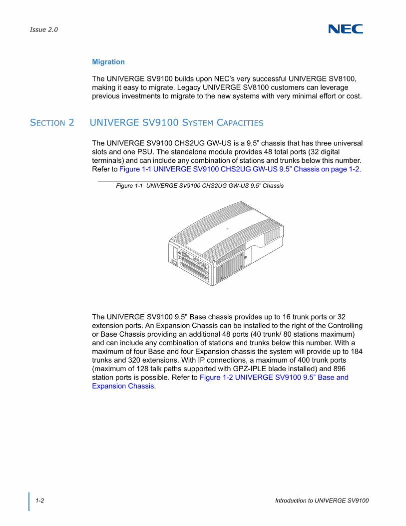
Figure 1-1 UNIVERGE SV9100 CHS2UG GW-US 9.5” Chassis ....................................................1-2
Figure 1-2 UNIVERGE SV9100 9.5” Base and Expansion Chassis ...............................................1-3
Figure 1-3 UNIVERGE SV9100 CHS2UG-US 19” Chassis Expandability ......................................1-3
Figure 1-4 UNIVERGE SV9100 Telephone Modular Design ..........................................................1-4
Figure 1-5 Simplified SV9100 System (9.5” Gateway and Base) Connectivity .............................1-13
Figure 1-6 Simplified SV9100 System (9.5” Base and Expansion) Connectivity ..........................1-14
Figure 1-7 Simplified SV9100 System (19”) Connectivity .............................................................1-14
Figure 5-1 Base and Expansion Chassis ........................................................................................5-1
Figure 5-2 UNIVERGE SV9100 CHS2UG GW-US Chassis ...........................................................5-2
Figure 5-3 CHS2UG B-US Base and CHS2UG E Expansion Chassis ...........................................5-4
Figure 5-4 Connecting the DLC Using Twisted 2-Pair Cable ........................................................5-18

vi List of Figures
Issue 2.0
SV9100 General Description Manual vii
LIST OF TABLES
Table R-1 Battery Types and Quantities for Chassis and Blades .............................................. R-7
Table 1-1 Terminal Category Reference Chart ..........................................................................1-7
Table 1-2 Connectivity of Options (DT300/DT700) ..................................................................1-11
Table 1-3 Connectivity of Options (DT400/DT800) ..................................................................1-12
Table 2-1 Feature Comparison List ............................................................................................2-1
Table 2-2 Selectable Display Messaging Defaults ...................................................................2-70
Table 3-1 Chassis Equipment List ..............................................................................................3-1
Table 3-2 Chassis Installation Equipment List ............................................................................3-1
Table 3-3 Battery Mount Equipment List ....................................................................................3-2
Table 3-4 Blade Equipment List .................................................................................................3-2
Table 3-5 Cable Equipment List .................................................................................................3-3
Table 3-6 Digital Multiline Terminal (DT300 Series) Equipment List ..........................................3-4
Table 3-7 Digital Multiline Terminal (DT400 Series) Equipment List ..........................................3-4
Table 3-8 IP Multiline Terminal (DT700 Series) Equipment List .................................................3-5
Table 3-9 IP Multiline Terminal (DT800 Series) Equipment List .................................................3-6
Table 3-10 DT300/DT700 Series Optional Equipment List ..........................................................3-6
Table 3-11 DT400/DT800 Series Optional Equipment List ........................................................3-11
Table 3-12 UT880 (IP Terminal) Equipment List ........................................................................3-12
Table 3-13 SV9100 Weights and Dimensions ............................................................................3-12
Table 5-1 9.5” Gateway and 19” Maximum System Capacities – Chassis .................................5-2
Table 5-2 9.5” Base and Expansion Maximum System Capacities – Chassis ...........................5-4
Table 5-3 SV9100 Maximum 9.5” Gateway and 19” System Capacities – Blades .....................5-5
Table 5-4 SV9100 Maximum 9.5” Base and Expansion System Capacities – Blades ...............5-8
Table 5-5 Daughter Board Combinations .................................................................................5-10
Table 5-6 SV9100 9.5” Gateway and 19” Maximum System Capacities – Trunks/Ports/Channels ........................................................................5-12
viii List of Tables
Issue 2.0
Table 5-7 SV9100 9.5” (Base and Expansion) Maximum System Capacities – Trunks/Ports/Channels ........................................................................ 5-13
Table 5-8 Board Power Factor ................................................................................................. 5-14
Table 5-9 Maximum Number of Packages Installed ................................................................. 5-14
Table 5-10 Terminal Power Factor ............................................................................................. 5-15
Table 5-11 IP Terminal Power Factor Chart – DT700 ................................................................ 5-16
Table 5-12 IP Terminal Power Factor Chart – DT800 ................................................................ 5-16
Table 5-13 IEEE802.af Class Specifications .............................................................................. 5-17
Table 5-14 Traffic Capacity ........................................................................................................ 5-17
Table 5-15 DT300/DT400 Series Loop Resistance and Cable Length ...................................... 5-19
Table 5-16 DT700/DT800 Series Loop Resistance and Cable Length ...................................... 5-19
Table 5-17 Cable Connection Between Analog Port and Single Line Equipment ...................... 5-20
Table 5-18 Cabling Requirements .............................................................................................. 5-21
Table 5-19 Power Consumption ................................................................................................. 5-22
Table 5-20 Mean Time Between Failure .................................................................................... 5-25
Table 5-21 Tone Patterns ........................................................................................................... 5-30
Table 5-22 Multiline Terminal LED Flash Pattern ....................................................................... 5-32
SV9100 General Description Manual 1-1
Chapter 1
UNIVERGE® SV9100
Introduction to UNIVERGE SV9100
SECTION 1 SYSTEM OVERVIEW
Designed specifically for small and medium-sized businesses (SMBs), the UNIVERGE SV9100 delivers voice over IP, unified communications and collaboration as well as mobility, all from a single, easy-to-manage solution. The new UNIVERGE SV9100 aligns with NEC’s Smart Enterprise strategy, an initiative to simplify technology and help companies create an agile, more responsive business environment.
Communications for SMB
The UNIVERGE SV9100 aligns with the needs of companies with fewer than 900 employees. NEC offers two variations of the UNIVERGE SV9100 to accommodate customers’ specific business needs.
The UNIVERGE SV9100-E can be deployed in either an all-IP or a hybrid IP/Digital environment, enabling companies to take full advantage of more advanced Unified Communications (UC) options.
The UNIVERGE SV9100-S is for companies that just want the basics for now, with the ability to grow in the future. The UNIVERGE SV9100-S enables easy migration to the UNIVERGE SV9100-E.
The UNIVERGE SV9100 facilitates smarter communications for the SMB. The solution includes a new, simplified licensing model to combine multiple applications and deliver them all as a single solution.
Voice and unified messaging
Powerful unified communications
Comprehensive contact-center suite
Broad range of mobility applications and devices
Vertical market-specific solutions
With these embedded components, companies can equip all employees with applications for a consistent, enhanced user experience across the organization.
Issue 2.0
1-2 Introduction to UNIVERGE SV9100
Migration
The UNIVERGE SV9100 builds upon NEC’s very successful UNIVERGE SV8100, making it easy to migrate. Legacy UNIVERGE SV8100 customers can leverage previous investments to migrate to the new systems with very minimal effort or cost.
SECTION 2 UNIVERGE SV9100 SYSTEM CAPACITIES
The UNIVERGE SV9100 CHS2UG GW-US is a 9.5” chassis that has three universal slots and one PSU. The standalone module provides 48 total ports (32 digital terminals) and can include any combination of stations and trunks below this number. Refer to Figure 1-1 UNIVERGE SV9100 CHS2UG GW-US 9.5” Chassis on page 1-2.
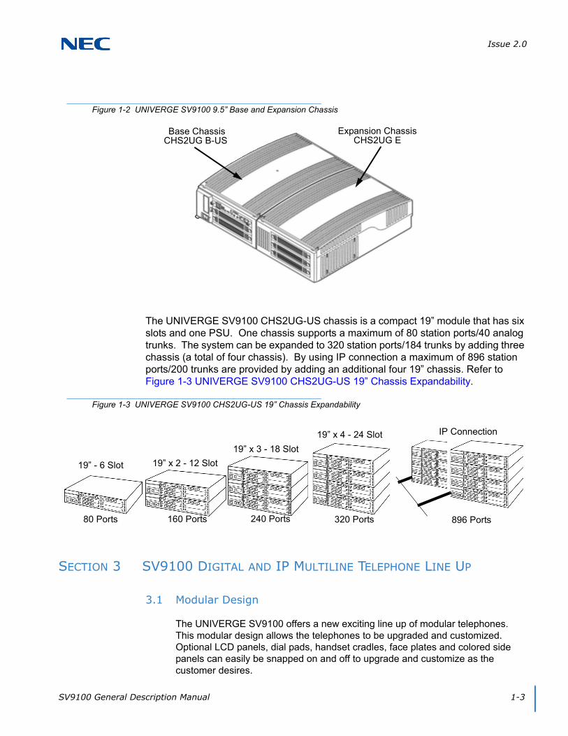
The UNIVERGE SV9100 9.5" Base chassis provides up to 16 trunk ports or 32 extension ports. An Expansion Chassis can be installed to the right of the Controlling or Base Chassis providing an additional 48 ports (40 trunk/ 80 stations maximum) and can include any combination of stations and trunks below this number. With a maximum of four Base and four Expansion chassis the system will provide up to 184 trunks and 320 extensions. With IP connections, a maximum of 400 trunk ports (maximum of 128 talk paths supported with GPZ-IPLE blade installed) and 896 station ports is possible. Refer to Figure 1-2 UNIVERGE SV9100 9.5” Base and Expansion Chassis.
Figure 1-1 UNIVERGE SV9100 CHS2UG GW-US 9.5” Chassis
Issue 2.0
SV9100 General Description Manual 1-3
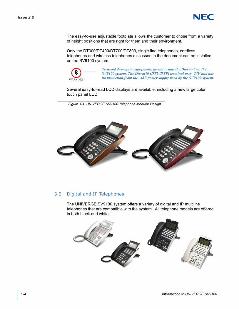
The UNIVERGE SV9100 CHS2UG-US chassis is a compact 19” module that has six slots and one PSU. One chassis supports a maximum of 80 station ports/40 analog trunks. The system can be expanded to 320 station ports/184 trunks by adding three chassis (a total of four chassis). By using IP connection a maximum of 896 station ports/200 trunks are provided by adding an additional four 19” chassis. Refer to Figure 1-3 UNIVERGE SV9100 CHS2UG-US 19” Chassis Expandability.
SECTION 3 SV9100 DIGITAL AND IP MULTILINE TELEPHONE LINE UP
3.1 Modular Design
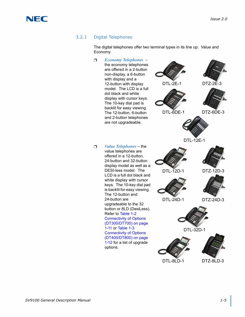
The UNIVERGE SV9100 offers a new exciting line up of modular telephones. This modular design allows the telephones to be upgraded and customized. Optional LCD panels, dial pads, handset cradles, face plates and colored side panels can easily be snapped on and off to upgrade and customize as the customer desires.
Figure 1-2 UNIVERGE SV9100 9.5” Base and Expansion Chassis
Base ChassisCHS2UG B-US
Expansion ChassisCHS2UG E
Figure 1-3 UNIVERGE SV9100 CHS2UG-US 19” Chassis Expandability
80 Ports 160 Ports
19” x 3 - 18 Slot
19” x 4 - 24 Slot
896 Ports
IP Connection
320 Ports240 Ports
19” x 2 - 12 Slot19” - 6 Slot
Issue 2.0
1-4 Introduction to UNIVERGE SV9100
The easy-to-use adjustable footplate allows the customer to chose from a variety of height positions that are right for them and their environment.
Only the DT300/DT400/DT700/DT800, single line telephones, cordless telephones and wireless telephones discussed in the document can be installed on the SV9100 system.
Several easy-to-read LCD displays are available, including a new large color touch panel LCD.
3.2 Digital and IP Telephones
The UNIVERGE SV9100 system offers a variety of digital and IP multiline telephones that are compatible with the system. All telephone models are offered in both black and white.
WARNING
To avoid damage to equipment, do not install the Dterm70 on the SV9100 system. The Dterm70 (DTU/DTP) terminal uses -24V and has no protection from the -48V power supply used by the SV9100 system.
Figure 1-4 UNIVERGE SV9100 Telephone Modular Design
Issue 2.0
SV9100 General Description Manual 1-5
3.2.1 Digital Telephones
The digital telephones offer two terminal types in its line up: Value and Economy.
Economy Telephones – the economy telephones are offered in a 2-button non-display, a 6-button with display and a 12-button with display model. The LCD is a full dot black and white display with cursor keys. The 10-key dial pad is backlit for easy viewing. The 12-button, 6-button and 2-button telephones are not upgradeable.
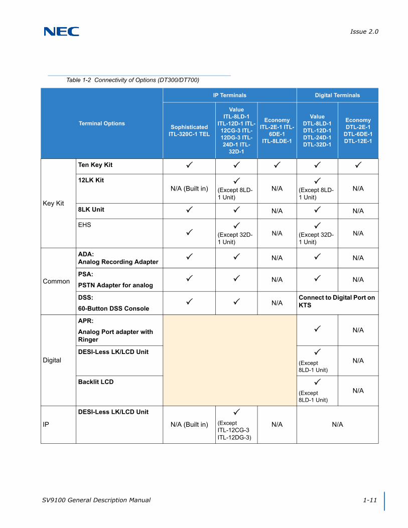
Value Telephones – the value telephones are offered in a 12-button, 24-button and 32-button display model as well as a DESI-less model. The LCD is a full dot black and white display with cursor keys. The 10-key dial pad is backlit for easy viewing. The 12-button and 24-button are upgradeable to the 32 button or 8LD (DesiLess). Refer to Table 1-2 Connectivity of Options (DT300/DT700) on page 1-11 or Table 1-3 Connectivity of Options (DT400/DT800) on page 1-12 for a list of upgrade options.
DTL-12E-1
DTL-2E-1 DTZ-2E-3
DTL-6DE-1 DTZ-6DE-3
DTL-12D-1 DTZ-12D-3
DTL-24D-1 DTZ-24D-3
DTL-32D-1
DTL-8LD-1 DTZ-8LD-3
Issue 2.0
1-6 Introduction to UNIVERGE SV9100
3.2.2 IP Telephones
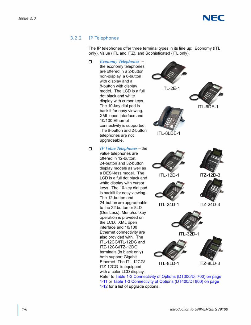
The IP telephones offer three terminal types in its line up: Economy (ITL only), Value (ITL and ITZ), and Sophisticated (ITL only).
Economy Telephones – the economy telephones are offered in a 2-button non-display, a 6-button with display and a 8-button with display model. The LCD is a full dot black and white display with cursor keys. The 10-key dial pad is backlit for easy viewing. XML open interface and 10/100 Ethernet connectivity is supported. The 6-button and 2-button telephones are not upgradeable.
IP Value Telephones – the value telephones are offered in 12-button, 24-button and 32-button display models as well as a DESI-less model. The LCD is a full dot black and white display with cursor keys. The 10-key dial pad is backlit for easy viewing. The 12-button and 24-button are upgradeable to the 32 button or 8LD (DesiLess). Menu/softkey operation is provided on the LCD. XML open interface and 10/100 Ethernet connectivity are also provided with. The ITL-12CG/ITL-12DG and ITZ-12CG/ITZ-12DG terminals (in black only) both support Gigabit Ethernet. The ITL-12CG/ITZ-12CG is equipped with a color LCD display. Refer to Table 1-2 Connectivity of Options (DT300/DT700) on page 1-11 or Table 1-3 Connectivity of Options (DT400/DT800) on page 1-12 for a list of upgrade options.
ITL-2E-1
ITL-6DE-1
ITL-8LDE-1
ITL-12D-1 ITZ-12D-3
ITL-24D-1 ITZ-24D-3
ITL-32D-1
ITL-8LD-1 ITZ-8LD-3
Issue 2.0
SV9100 General Description Manual 1-7
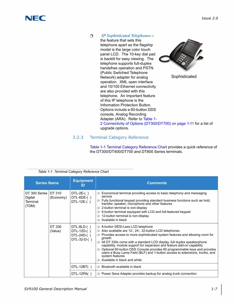
IP Sophisticated Telephones – the feature that sets this telephone apart as the flagship model is the large color touch panel LCD. The 10-key dial pad is backlit for easy viewing. The telephone supports full-duplex handsfree operation and PSTN (Public Switched Telephone Network) adapter for analog operation. XML open interface and 10/100 Ethernet connectivity are also provided with this telephone. An important feature of this IP telephone is the Information Protection Button. Options include a 60-button DDS console, Analog Recording Adapter (ARA). Refer to Table 1-2 Connectivity of Options (DT300/DT700) on page 1-11 for a list of upgrade options.
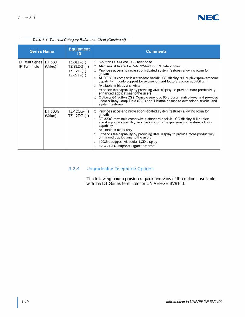
3.2.3 Terminal Category Reference
Table 1-1 Terminal Category Reference Chart provides a quick reference of the DT300/DT400/DT700 and DT800 Series terminals.
Sophisticated
Table 1-1 Terminal Category Reference Chart
Series NameEquipment
IDComments
DT 300 SeriesDigital Terminal (TDM)
DT 310(Economy)
DTL-2E-( )DTL-6DE-( )DTL-12E-( )
Economical terminal providing access to basic telephony and messaging service
Fully functional keypad providing standard business functions such as hold, transfer, speaker, microphone and other features
2-button terminal is non-display 6-button terminal equipped with LCD and full-featured keypad 12-button terminal is non-display Available in black
DT 330(Value)
DTL-8LD-( )DTL-12D-( )DTL-24D-( )DTL-32-D-( )
8-button DESI-Less LCD telephone Also available are 12-, 24-, 32-button LCD telephones Provides access to more sophisticated system features and allowing room for
growth All DT 330s come with a standard LCD display, full duplex speakerphone
capability, module support for expansion and feature add-on capability Optional 60-button DSS Console provides 60 programmable keys and provides
users a Busy Lamp Field (BLF) and 1-button access to extensions, trunks, and system features
Available in black and white
DTL-12BT( ) Bluetooth available in black
DTL-12PA( ) Power Save Adapter provides backup for analog trunk connection
Issue 2.0
1-8 Introduction to UNIVERGE SV9100
DT 400 SeriesDigital Terminal (TDM)
DT 410(Economy)
DTZ-2E-( )DTZ-6DE-( )
Economical terminal providing access to basic telephony and messaging service
Fully functional keypad providing standard business functions such as hold, transfer, speaker, microphone and other features
2-button terminal is non-display 6-button terminal equipped with LCD and full-featured keypad Available in black
DT 430(Value)
DTZ-8LD-( )DTZ-12D-( )DTZ-24D-( )
8-button DESI-Less LCD telephone Also available are 12-, 24-, 32-button LCD telephones Provides access to more sophisticated system features and allowing room for
growth All DT 430s come with a standard LCD display, full duplex speakerphone
capability, module support for expansion and feature add-on capability Optional 60-button DSS Console provides 60 programmable keys and provides
users a Busy Lamp Field (BLF) and 1-button access to extensions, trunks, and system features
Available in black and white
Table 1-1 Terminal Category Reference Chart (Continued)
Series NameEquipment
IDComments
Issue 2.0
SV9100 General Description Manual 1-9
DT 700 SeriesIP Terminals
DT 710(Economy)
ITL-2E-( )ITL-6DE-( )ITL-8LDE-( )
Economical terminal providing access to basic telephony and messaging service
Fully functional keypad providing standard business functions such as hold, transfer, speaker, microphone and other features
2-button terminal is non-display 6-button terminal equipped with LCD and full-featured keypad 8-button terminal equipped with LCD and full-featured keypad Available in black IP formatted terminal has a dual port, supports compression, full-duplex
handsfree operation
DT 730(Value)
ITL-8LD-( )ITL-12D-( )ITL-24D-( )ITL-32-D-( )
8-button DESI-Less LCD telephone Also available are 12-, 24-, 32-button LCD telephones Provides access to more sophisticated system features allowing room for
growth All DT 730s come with a standard backlit LCD display, full duplex speakerphone
capability, module support for expansion and feature add-on capability Available in black and white Expands the capability by providing XML display to provide more productivity
enhanced applications to the users Optional 60-button DSS Console provides 60 programmable keys and provides
users a Busy Lamp Field (BLF) and 1-button access to extensions, trunks, and system features
ITL-12PA( ) Power Save Adapter provides backup for analog trunk connection
DT 730G(Value)
ITL-12CG-( )ITL-12DG-( )
Provides access to more sophisticated system features allowing room for growth
DT 730G terminals come with a standard back-lit LCD display, full duplex speakerphone capability, module support for expansion and feature add-on capability
Available in black only Expands the capability by providing XML display to provide more productivity
enhanced applications to the users 12CG equipped with color LCD display 12CG/12DG support Gigabit Ethernet
DT 750(Sophisticated)
ITL-320C-( ) IP terminal provides a 5” color touch panel Features of the telephone provide easy use of NEC Unified communications
and third-party telephony XML applications Access to 32 telephony feature lines across an IP backbone, built-in full duplex
speakerphone and DESI-Less line key labeling are standard Optional 60-button DSS Console provides 60 programmable keys and provides
users a Busy Lamp Field (BLF) and one-button access to extensions, trunks, and system features
Wireless Handset G955 SIP DECT
G266 SIP DECT
G566 SIP DECT
ML440 SIP DECT
Cordless DTL-8R-1 Cordless DECT
DTZ-8R-1 Cordless DECT
Table 1-1 Terminal Category Reference Chart (Continued)
Series NameEquipment
IDComments
Issue 2.0
1-10 Introduction to UNIVERGE SV9100
3.2.4 Upgradeable Telephone Options
The following charts provide a quick overview of the options available with the DT Series terminals for UNIVERGE SV9100.
DT 800 SeriesIP Terminals
DT 830(Value)
ITZ-8LD-( )ITZ-8LDG-( )ITZ-12D-( )ITZ-24D-( )
8-button DESI-Less LCD telephone Also available are 12-, 24-, 32-button LCD telephones Provides access to more sophisticated system features allowing room for
growth All DT 830s come with a standard backlit LCD display, full duplex speakerphone
capability, module support for expansion and feature add-on capability Available in black and white Expands the capability by providing XML display to provide more productivity
enhanced applications to the users Optional 60-button DSS Console provides 60 programmable keys and provides
users a Busy Lamp Field (BLF) and 1-button access to extensions, trunks, and system features
DT 830G(Value)
ITZ-12CG-( )ITZ-12DG-( )
Provides access to more sophisticated system features allowing room for growth
DT 830G terminals come with a standard back-lit LCD display, full duplex speakerphone capability, module support for expansion and feature add-on capability
Available in black only Expands the capability by providing XML display to provide more productivity
enhanced applications to the users 12CG equipped with color LCD display 12CG/12DG support Gigabit Ethernet
Table 1-1 Terminal Category Reference Chart (Continued)
Series NameEquipment
IDComments
Issue 2.0
SV9100 General Description Manual 1-11
Table 1-2 Connectivity of Options (DT300/DT700)
Terminal Options
IP Terminals Digital Terminals
SophisticatedITL-320C-1 TEL
ValueITL-8LD-1
ITL-12D-1 ITL-12CG-3 ITL-12DG-3 ITL-24D-1 ITL-
32D-1
EconomyITL-2E-1 ITL-
6DE-1ITL-8LDE-1
ValueDTL-8LD-1 DTL-12D-1 DTL-24D-1 DTL-32D-1
EconomyDTL-2E-1
DTL-6DE-1DTL-12E-1
Key Kit
Ten Key Kit
12LK KitN/A (Built in)
(Except 8LD-1 Unit)
N/A
(Except 8LD-1 Unit)
N/A
8LK Unit N/A N/A
EHS
(Except 32D-1 Unit)
N/A
(Except 32D-1 Unit)
N/A
Common
ADA:Analog Recording Adapter N/A N/A
PSA:
PSTN Adapter for analog N/A N/A
DSS:
60-Button DSS Console N/A
Connect to Digital Port on KTS
Digital
APR:
Analog Port adapter with Ringer
N/A
DESI-Less LK/LCD Unit (Except8LD-1 Unit)
N/A
Backlit LCD (Except8LD-1 Unit)
N/A
IP
DESI-Less LK/LCD Unit
N/A (Built in)
(ExceptITL-12CG-3 ITL-12DG-3)
N/A N/A
Issue 2.0
1-12 Introduction to UNIVERGE SV9100
3.3 Equipment and Applications Overview
The primary target of the UNIVERGE SV9100 system is the small to medium-sized business. As such, it supports a number of robust applications and additional equipment that add value to the system. These include:
Contact Center
Voice Mail
Computer Telephone Integration (CTI)
Unified Messaging
Wireless Handsets
Station Message Detail Recording (SMDR)
Single Line Telephones
Table 1-3 Connectivity of Options (DT400/DT800)
Terminal Options
IP Terminals Digital Terminals
ValueITZ-8LD-3
ITZ-8LDG-3ITZ-12D-3ITZ-24D-3
ITZ-12CG-3ITZ-12DG-3
ValueDTZ-8LD-3 DTZ-12D-3 DTZ-24D-3
EconomyDTZ-2E-3
DTZ-6DE-3
Key Kit
Ten Key Kit
12LK Kit
ITZ-12CG/12DG only
(Except 8LD-3 Unit)
N/A
8LK Unit N/A
Common
ADA:Analog Recording Adapter N/A
DSS:
60-Button DSS Console
Connect to Digital Port on KTS
Digital
APR:
Analog Port adapter with Ringer
N/A
Issue 2.0
SV9100 General Description Manual 1-13
External Speakerphones
Doorphones
External Speakers
Wireless DECT SIP
CO/PBX lines, Centrex lines, Direct Inward Dialing (DID), Tie lines, FT1 lines, ISDN-BRI and ISDN-PRI line
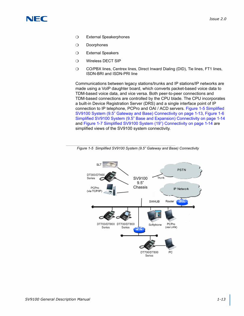
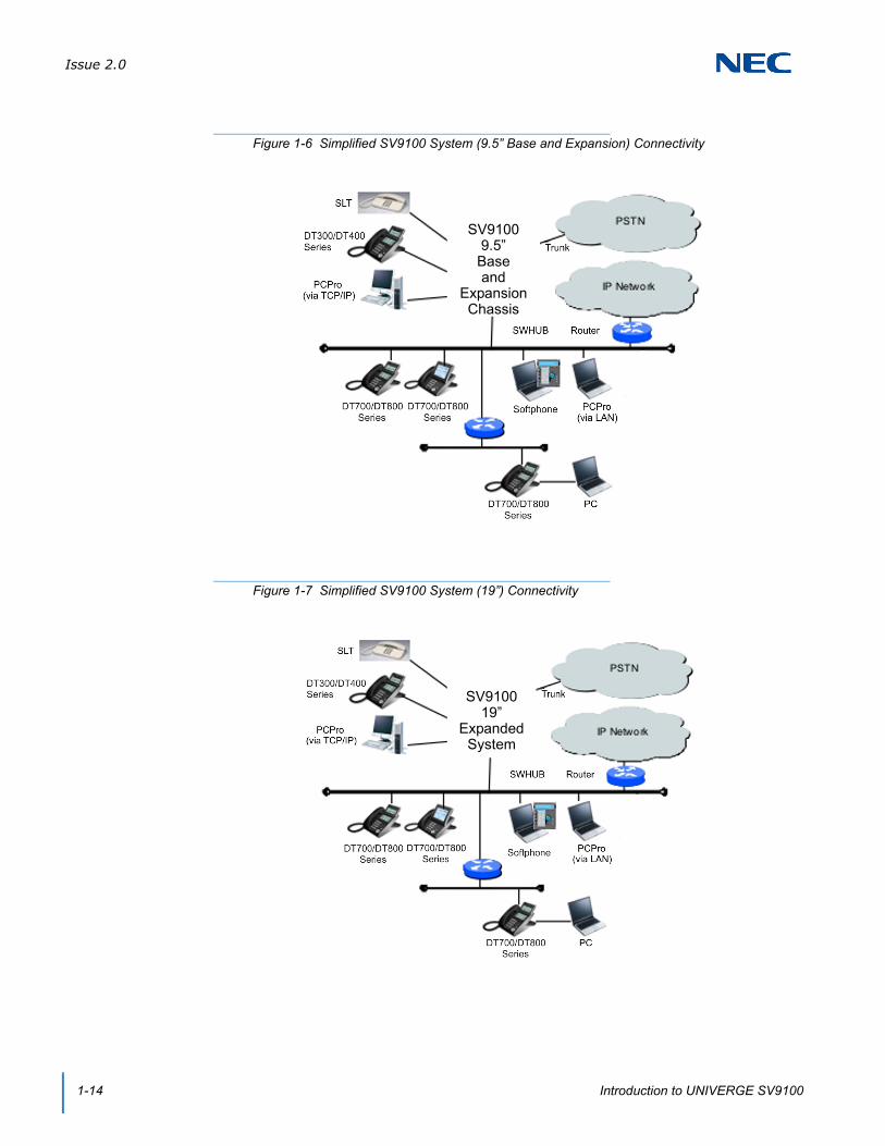
Communications between legacy stations/trunks and IP stations/IP networks are made using a VoIP daughter board, which converts packet-based voice data to TDM-based voice data, and vice versa. Both peer-to-peer connections and TDM-based connections are controlled by the CPU blade. The CPU incorporates a built-in Device Registration Server (DRS) and a single interface point of IP connection to IP telephone, PCPro and OAI / ACD servers. Figure 1-5 Simplified SV9100 System (9.5” Gateway and Base) Connectivity on page 1-13, Figure 1-6 Simplified SV9100 System (9.5” Base and Expansion) Connectivity on page 1-14 and Figure 1-7 Simplified SV9100 System (19”) Connectivity on page 1-14 are simplified views of the SV9100 system connectivity.
Figure 1-5 Simplified SV9100 System (9.5” Gateway and Base) Connectivity
SV91009.5”
Chassis
Issue 2.0
1-14 Introduction to UNIVERGE SV9100
Figure 1-6 Simplified SV9100 System (9.5” Base and Expansion) Connectivity
Figure 1-7 Simplified SV9100 System (19”) Connectivity
SV91009.5”Baseand
Expansion Chassis
SV910019”
ExpandedSystem
SV9100 General Description Manual 2-1
Chapter 2
UNIVERGE® SV9100
Features
SECTION 1 OVERVIEW
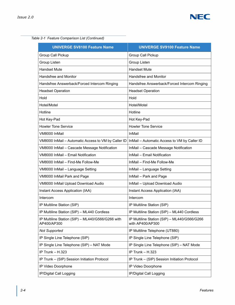
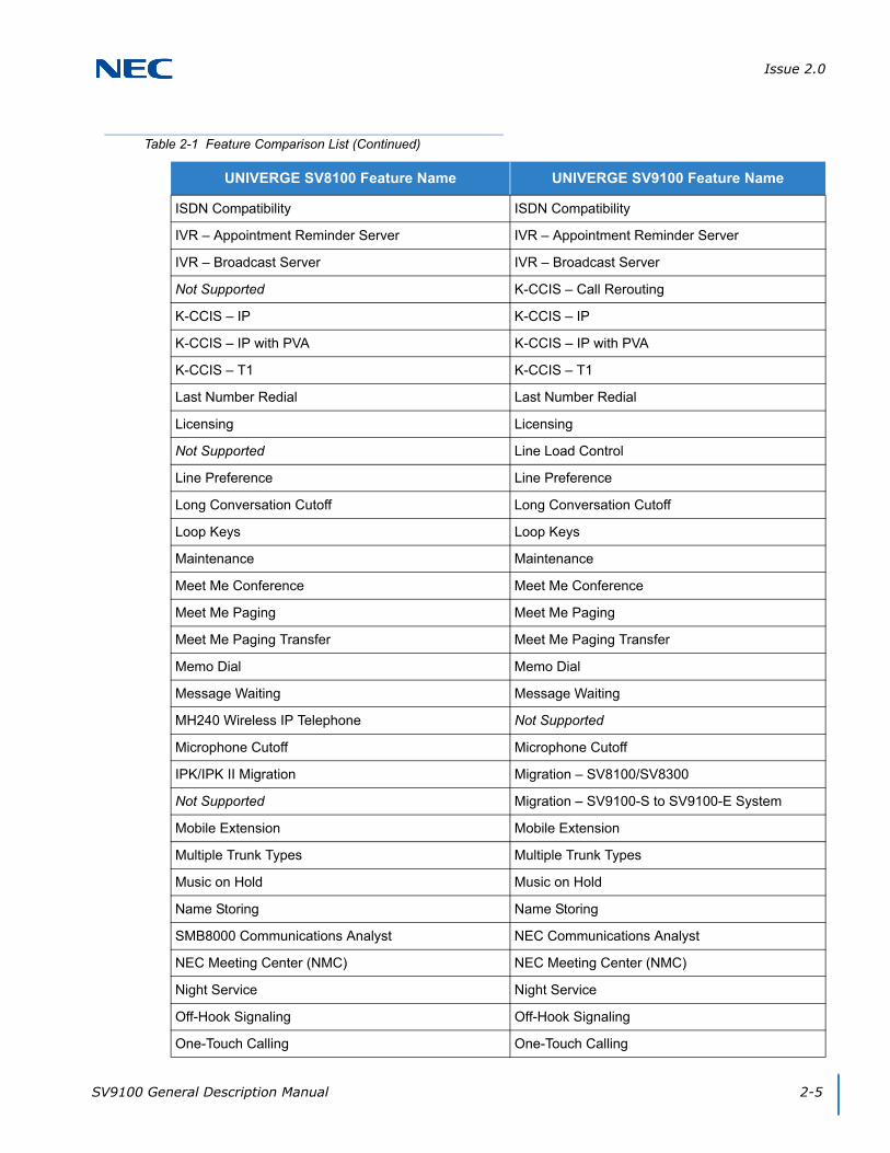
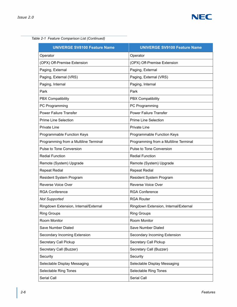
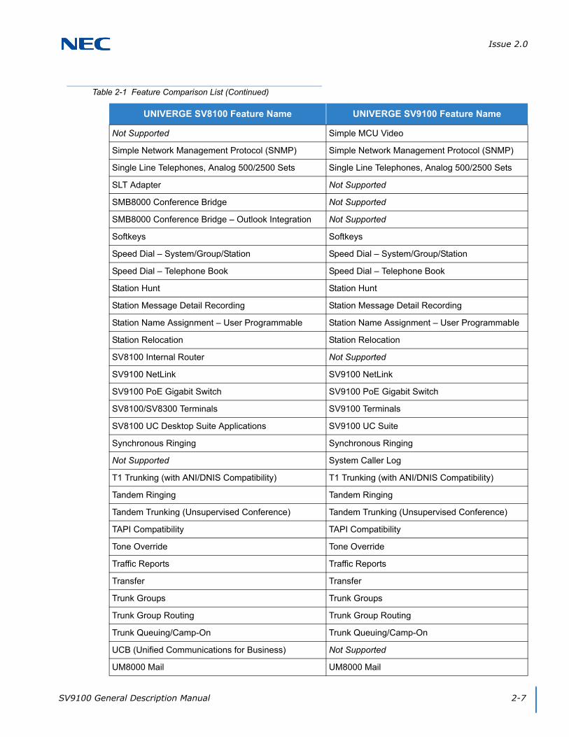
This chapter provides a feature comparison list, which compares the UNIVERGE SV8100 and UNIVERGE SV9100 feature names.
The remainder of the chapter provides a list of all UNIVERGE SV9100 features and a brief description. For a more detailed description of the feature, refer to the UNIVERGE SV9100 Features and Specifications Manual.
SECTION 2 UNIVERGE SV8100 TO UNIVERGE SV9100 FEATURE COMPARISON LIST
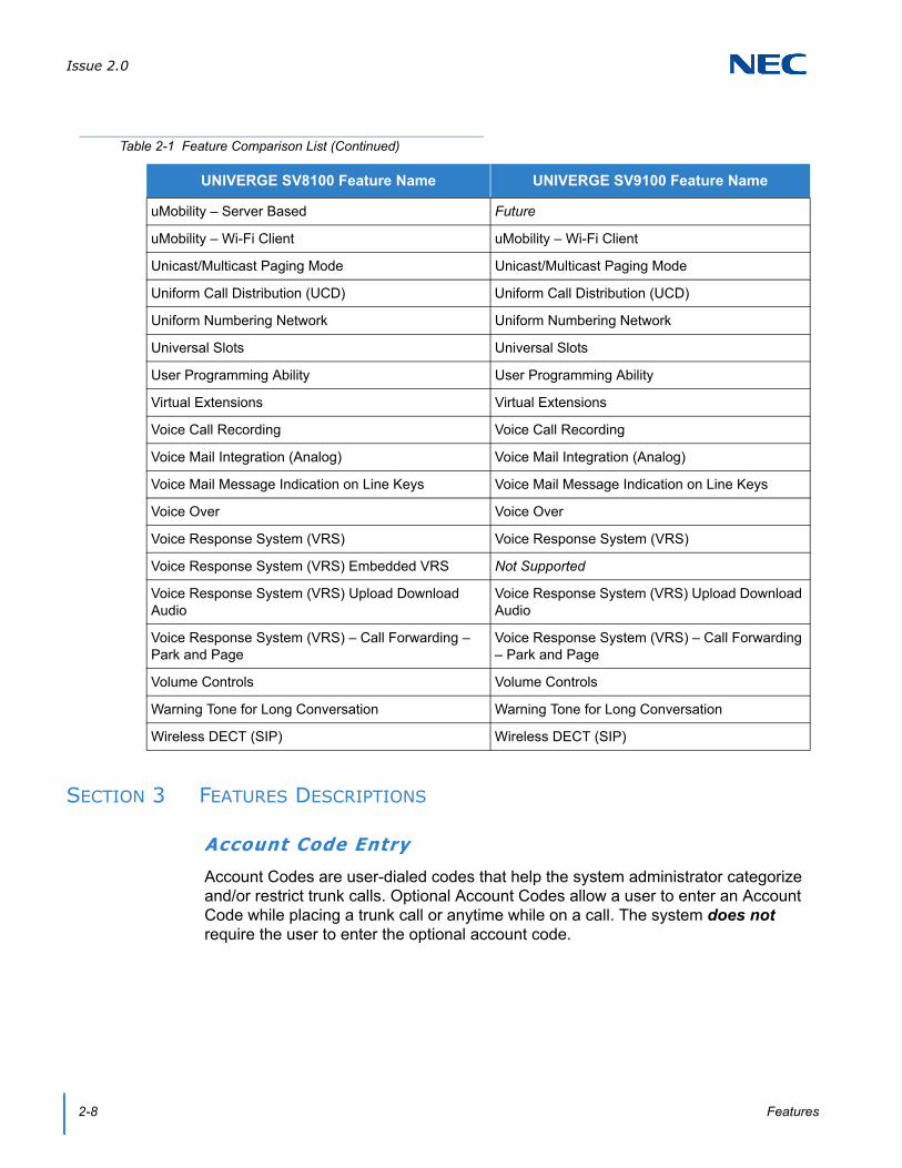
Table 2-1 Feature Comparison List provides a cross-reference between the UNIVERGE SV8100 and the UNIVERGE SV9100 features.
Table 2-1 Feature Comparison List
UNIVERGE SV8100 Feature Name UNIVERGE SV9100 Feature Name
Account Code Entry Account Code Entry
Account Code – Forced/Verified/Unverified Account Code – Forced/Verified/Unverified
Alarm Alarm
Alarm Reports Alarm Reports
Alphanumeric Display Alphanumeric Display
Analog Communications Interface (ACI) Analog Communications Interface (ACI)
Ancillary Device Connection Ancillary Device Connection
Answer Hold Answer Hold
Answer Key Answer Key
Attendant Call Queuing Attendant Call Queuing
Automatic Release Automatic Release
Automatic Route Selection (ARS) Automatic Route Selection (ARS)
Background Music Background Music
Barge-In Barge-In
Battery Backup – System Memory Battery Backup – System Memory
Issue 2.0
2-2 Features
Battery Backup – System Power Battery Backup – System Power
Callback Callback
Caller ID Caller Return Caller ID Caller Return
Caller ID Caller ID
Caller ID – Flexible Ringing Caller ID – Flexible Ringing
Caller ID – Memo Display Function Caller ID – Memo Display Function
Call Appearance (CAP) Keys Call Appearance (CAP) Keys
Call Arrival (CAR) Keys Call Arrival (CAR) Keys
Call Duration Timer Call Duration Timer
Call Forwarding Call Forwarding
Call Forwarding with Follow Me Call Forwarding with Follow Me
Call Forwarding – Centrex Call Forwarding – Centrex
Call Forwarding, Off-Premise Call Forwarding, Off-Premise
Call Forwarding/Do Not Disturb Override Call Forwarding/Do Not Disturb Override
Call Monitoring Call Monitoring
Call Redirect Call Redirect
Call Waiting/Camp-On Call Waiting/Camp-On
Central Office Calls, Answering Central Office Calls, Answering
Central Office Calls, Placing Central Office Calls, Placing
Class of Service Class of Service
Clock/Calendar Display Clock/Calendar Display
Code Restriction Code Restriction
Code Restriction Override Code Restriction Override
Code Restriction, Dial Block Code Restriction, Dial Block
Conference Conference
Not Supported Conference – Remote
Not Supported Conference – Remote Conference Recording
Conference, Voice Call/Privacy Release Conference, Voice Call/Privacy Release
Automatic Call Distribution (ACD) Contact Center
Continued Dialing Continued Dialing
Cordless DECT Terminals Cordless DECT Terminals
Cordless Telephone Connection Cordless Telephone Connection
Table 2-1 Feature Comparison List (Continued)
UNIVERGE SV8100 Feature Name UNIVERGE SV9100 Feature Name
Issue 2.0
SV9100 General Description Manual 2-3
CO Message Waiting Indication CO Message Waiting Indication
Data Line Security Data Line Security
Delayed Ringing Delayed Ringing
Department Calling Department Calling
Department Step Calling Department Step Calling
Dialing Number Preview Dialing Number Preview
Dial Pad Confirmation Tone Dial Pad Confirmation Tone
Dial Tone Detection Dial Tone Detection
Digital Trunk Clocking Digital Trunk Clocking
Directed Call Pickup Directed Call Pickup
Directory Dialing Directory Dialing
Direct Inward Dialing (DID) Direct Inward Dialing (DID)
Direct Inward Line (DIL) Direct Inward Line (DIL)
Direct Inward System Access (DISA) Direct Inward System Access (DISA)
Direct Station Selection (DSS) Console Direct Station Selection (DSS) Console
Distinctive Ringing, Tones and Flash Patterns Distinctive Ringing, Tones and Flash Patterns
Door Box Door Box
Do Not Disturb Do Not Disturb
Drop Key Drop Key
Dterm Cordless II Terminal Not Supported
Dterm Cordless Lite II Terminal Not Supported
DTPlusWare Not Supported
Ecology Ecology
Electra Elite IPK Terminals Not Supported
E911 Compatibility E911 Compatibility
Facsimile CO Branch Connection Facsimile CO Branch Connection
Flash Flash
Flexible System Numbering Flexible System Numbering
Flexible Timeouts Flexible Timeouts
Forced Trunk Disconnect Forced Trunk Disconnect
General Purpose Relay General Purpose Relay
Table 2-1 Feature Comparison List (Continued)
UNIVERGE SV8100 Feature Name UNIVERGE SV9100 Feature Name
Issue 2.0
2-4 Features
Group Call Pickup Group Call Pickup
Group Listen Group Listen
Handset Mute Handset Mute
Handsfree and Monitor Handsfree and Monitor
Handsfree Answerback/Forced Intercom Ringing Handsfree Answerback/Forced Intercom Ringing
Headset Operation Headset Operation
Hold Hold
Hotel/Motel Hotel/Motel
Hotline Hotline
Hot Key-Pad Hot Key-Pad
Howler Tone Service Howler Tone Service
VM8000 InMail InMail
VM8000 InMail – Automatic Access to VM by Caller ID InMail – Automatic Access to VM by Caller ID
VM8000 InMail – Cascade Message Notification InMail – Cascade Message Notification
VM8000 InMail – Email Notification InMail – Email Notification
VM8000 InMail – Find-Me Follow-Me InMail – Find-Me Follow-Me
VM8000 InMail – Language Setting InMail – Language Setting
VM8000 InMail Park and Page InMail – Park and Page
VM8000 InMail Upload Download Audio InMail – Upload Download Audio
Instant Access Application (IAA) Instant Access Application (IAA)
Intercom Intercom
IP Multiline Station (SIP) IP Multiline Station (SIP)
IP Multiline Station (SIP) – ML440 Cordless IP Multiline Station (SIP) – ML440 Cordless
IP Multiline Station (SIP) – ML440/G566/G266 with AP400/AP300
IP Multiline Station (SIP) – ML440/G566/G266 with AP400/AP300
Not Supported IP Multiline Telephone (UT880)
IP Single Line Telephone (SIP) IP Single Line Telephone (SIP)
IP Single Line Telephone (SIP) – NAT Mode IP Single Line Telephone (SIP) – NAT Mode
IP Trunk – H.323 IP Trunk – H.323
IP Trunk – (SIP) Session Initiation Protocol IP Trunk – (SIP) Session Initiation Protocol
IP Video Doorphone IP Video Doorphone
IP/Digital Call Logging IP/Digital Call Logging
Table 2-1 Feature Comparison List (Continued)
UNIVERGE SV8100 Feature Name UNIVERGE SV9100 Feature Name
Issue 2.0
SV9100 General Description Manual 2-5
ISDN Compatibility ISDN Compatibility
IVR – Appointment Reminder Server IVR – Appointment Reminder Server
IVR – Broadcast Server IVR – Broadcast Server
Not Supported K-CCIS – Call Rerouting
K-CCIS – IP K-CCIS – IP
K-CCIS – IP with PVA K-CCIS – IP with PVA
K-CCIS – T1 K-CCIS – T1
Last Number Redial Last Number Redial
Licensing Licensing
Not Supported Line Load Control
Line Preference Line Preference
Long Conversation Cutoff Long Conversation Cutoff
Loop Keys Loop Keys
Maintenance Maintenance
Meet Me Conference Meet Me Conference
Meet Me Paging Meet Me Paging
Meet Me Paging Transfer Meet Me Paging Transfer
Memo Dial Memo Dial
Message Waiting Message Waiting
MH240 Wireless IP Telephone Not Supported
Microphone Cutoff Microphone Cutoff
IPK/IPK II Migration Migration – SV8100/SV8300
Not Supported Migration – SV9100-S to SV9100-E System
Mobile Extension Mobile Extension
Multiple Trunk Types Multiple Trunk Types
Music on Hold Music on Hold
Name Storing Name Storing
SMB8000 Communications Analyst NEC Communications Analyst
NEC Meeting Center (NMC) NEC Meeting Center (NMC)
Night Service Night Service
Off-Hook Signaling Off-Hook Signaling
One-Touch Calling One-Touch Calling
Table 2-1 Feature Comparison List (Continued)
UNIVERGE SV8100 Feature Name UNIVERGE SV9100 Feature Name
Issue 2.0
2-6 Features
Operator Operator
(OPX) Off-Premise Extension (OPX) Off-Premise Extension
Paging, External Paging, External
Paging, External (VRS) Paging, External (VRS)
Paging, Internal Paging, Internal
Park Park
PBX Compatibility PBX Compatibility
PC Programming PC Programming
Power Failure Transfer Power Failure Transfer
Prime Line Selection Prime Line Selection
Private Line Private Line
Programmable Function Keys Programmable Function Keys
Programming from a Multiline Terminal Programming from a Multiline Terminal
Pulse to Tone Conversion Pulse to Tone Conversion
Redial Function Redial Function
Remote (System) Upgrade Remote (System) Upgrade
Repeat Redial Repeat Redial
Resident System Program Resident System Program
Reverse Voice Over Reverse Voice Over
RGA Conference RGA Conference
Not Supported RGA Router
Ringdown Extension, Internal/External Ringdown Extension, Internal/External
Ring Groups Ring Groups
Room Monitor Room Monitor
Save Number Dialed Save Number Dialed
Secondary Incoming Extension Secondary Incoming Extension
Secretary Call Pickup Secretary Call Pickup
Secretary Call (Buzzer) Secretary Call (Buzzer)
Security Security
Selectable Display Messaging Selectable Display Messaging
Selectable Ring Tones Selectable Ring Tones
Serial Call Serial Call
Table 2-1 Feature Comparison List (Continued)
UNIVERGE SV8100 Feature Name UNIVERGE SV9100 Feature Name
Issue 2.0
SV9100 General Description Manual 2-7
Not Supported Simple MCU Video
Simple Network Management Protocol (SNMP) Simple Network Management Protocol (SNMP)
Single Line Telephones, Analog 500/2500 Sets Single Line Telephones, Analog 500/2500 Sets
SLT Adapter Not Supported
SMB8000 Conference Bridge Not Supported
SMB8000 Conference Bridge – Outlook Integration Not Supported
Softkeys Softkeys
Speed Dial – System/Group/Station Speed Dial – System/Group/Station
Speed Dial – Telephone Book Speed Dial – Telephone Book
Station Hunt Station Hunt
Station Message Detail Recording Station Message Detail Recording
Station Name Assignment – User Programmable Station Name Assignment – User Programmable
Station Relocation Station Relocation
SV8100 Internal Router Not Supported
SV9100 NetLink SV9100 NetLink
SV9100 PoE Gigabit Switch SV9100 PoE Gigabit Switch
SV8100/SV8300 Terminals SV9100 Terminals
SV8100 UC Desktop Suite Applications SV9100 UC Suite
Synchronous Ringing Synchronous Ringing
Not Supported System Caller Log
T1 Trunking (with ANI/DNIS Compatibility) T1 Trunking (with ANI/DNIS Compatibility)
Tandem Ringing Tandem Ringing
Tandem Trunking (Unsupervised Conference) Tandem Trunking (Unsupervised Conference)
TAPI Compatibility TAPI Compatibility
Tone Override Tone Override
Traffic Reports Traffic Reports
Transfer Transfer
Trunk Groups Trunk Groups
Trunk Group Routing Trunk Group Routing
Trunk Queuing/Camp-On Trunk Queuing/Camp-On
UCB (Unified Communications for Business) Not Supported
UM8000 Mail UM8000 Mail
Table 2-1 Feature Comparison List (Continued)
UNIVERGE SV8100 Feature Name UNIVERGE SV9100 Feature Name
Issue 2.0
2-8 Features
SECTION 3 FEATURES DESCRIPTIONS
Account Code Entry
Account Codes are user-dialed codes that help the system administrator categorize and/or restrict trunk calls. Optional Account Codes allow a user to enter an Account Code while placing a trunk call or anytime while on a call. The system does not require the user to enter the optional account code.
uMobility – Server Based Future
uMobility – Wi-Fi Client uMobility – Wi-Fi Client
Unicast/Multicast Paging Mode Unicast/Multicast Paging Mode
Uniform Call Distribution (UCD) Uniform Call Distribution (UCD)
Uniform Numbering Network Uniform Numbering Network
Universal Slots Universal Slots
User Programming Ability User Programming Ability
Virtual Extensions Virtual Extensions
Voice Call Recording Voice Call Recording
Voice Mail Integration (Analog) Voice Mail Integration (Analog)
Voice Mail Message Indication on Line Keys Voice Mail Message Indication on Line Keys
Voice Over Voice Over
Voice Response System (VRS) Voice Response System (VRS)
Voice Response System (VRS) Embedded VRS Not Supported
Voice Response System (VRS) Upload Download Audio
Voice Response System (VRS) Upload Download Audio
Voice Response System (VRS) – Call Forwarding – Park and Page
Voice Response System (VRS) – Call Forwarding – Park and Page
Volume Controls Volume Controls
Warning Tone for Long Conversation Warning Tone for Long Conversation
Wireless DECT (SIP) Wireless DECT (SIP)
Table 2-1 Feature Comparison List (Continued)
UNIVERGE SV8100 Feature Name UNIVERGE SV9100 Feature Name
Issue 2.0
SV9100 General Description Manual 2-9
Account Code – Forced/Verified/Unverified
Account Codes are user-dialed codes that help the system administrator categorize and/or restrict trunk calls. The system has two types of Forced Account Codes:
Forced Account Codes (Unverified)
Verified Account Codes
Alarm
Alarm lets any station extension work like an Alarm clock. An extension user can have an Alarm remind them of a meeting or an appointment. There are two types of Alarms:
Alarm 1 (sounds only once at the preset time)
Alarm 2 (sounds every day at the preset time)
Alarm Reports
The UNIVERGE SV9100 system logs various errors and reports information about the operation that can be used to determine the cause of a problem. The system can indicate several errors on the multiline telephone display, output to a USB stick on the GCD-CP10, or be downloaded in PCPro. The report data also can be sent via email.
Enhancements
With SV9100 Version 2.00, Alarm indication can lamp (illuminate) a function key for Minor and Major alarms with the error type [ERR]. When a Minor or Major alarm occurs, the function key will light until cleared by the Clear Alarm Report service code (11-10-53) or Program 90-53-01.
Alphanumeric Display
Multibutton display telephones have a 3-line, 24 character per line alphanumeric display that provides various feature status messages. These messages help the display telephone user process calls, identify callers and customize features.
The contrast is not adjustable when the telephone has background music enabled.
Analog Communications Interface (ACI)
The Analog Communications Interface (ACI) feature uses a PGD(2)-U10 ADP (Door Phone/Paging) adapter to provide two analog ports (with associated relays) for Music on Hold, External Paging, Door Boxes and auxiliary devices such as tape recorders and loud bells. The system allows up to 48 PGD(2)-U10 ADPs (when used for ACI ports) for a maximum of 96 analog ports. Each PGD(2)-U10 ADP requires an unused port on a GCD-8DLCA/GCD-16DLCA blade.
Issue 2.0
2-10 Features
Ancillary Device Connection
Ancillary Device Connection allows installation of selected peripheral (ancillary) devices to a multiline terminal. This feature enhances peripheral device objectives.
An UNIVERGE SV9100 multiline terminal user can accomplish this by using the AP(R)-R/APR-L Unit (Analog Port Adapter with Ringer) or AP(A)-R Unit (Analog Port Adapter without Ringer) for analog telephone devices, or installing the AD(A)-R/APA-L Unit to connect devices such as tape recorders.
The AP(A)-R/AP(R)-R/APA-L Units are the interface for installing a single line telephone, Modem, credit card reader, wireless headset, NEC Conference Max Conferencing unit or other compatible analog device.
The PSA-L Unit (Power Save Adapter), an optional adapter for the ITL/DTL Terminals, is used to make or receive a call using the Public Switched Telephone Network (PSTN) when a call cannot be made with the ITL/DTL extension.
Answer Hold
Answer Hold allows a multiline terminal user to press the flashing Answer key to answer an incoming ringing call or a Camp-on call. When the multiline terminal user is already answering a call, the first call is automatically placed on hold, depending on the user setting in Program 15-02-06.
Answer Key
Multiline terminals have an Answer Key with an LED that flashes when the multiline terminal user receives an incoming CO/PBX, Tie/DID transfer, or CO/PBX transfer call. When multiple calls are received, the Answer Key is used to pick up calls and continues flashing until the last unanswered call is answered. Press the Answer Key during a call to hold the current call and allow the next call to be answered.
Attendant Call Queuing
Attendant extensions can have up to 32 incoming calls queued before additional callers hear a busy tone. This helps minimize call congestion in systems that use the attendant as the overflow destination for unanswered calls. For example, you can program Direct Inward Lines and Voice Mail calls to route to the attendant when their primary destination is busy. With Attendant Call Queuing, these unanswered calls would normally “stack up” for the attendant until they can be processed.
The 32 call queue total includes Intercom, DISA, DID, DIL, tie line and transferred calls. If the attendant does not have an appearance for the queued call, it waits in line to be answered. If the attendant has more than 32 calls queued, an extension can transfer a call to the attendant only if they have Busy Transfer enabled.
Attendant Call Queuing is a permanent, non-programmable system feature.
Issue 2.0
SV9100 General Description Manual 2-11
Automatic Release
Automatic Release drops the line circuit when an outside party abandons the call. For this feature to work with Loop Start Trunks, the CO/PBX providing the outside line must provide a timed disconnect signal. Automatic Release is normally provided on Ground Start, DID, ISDN, and Tie Line trunks.
Automatic Route Selection (ARS)
Automatic Route Selection (ARS) provides call routing and call restriction based on the digits a user dials. ARS gives the system the most cost-effective use of the connected long distance carriers.
ARS is an on-line call routing program that you can customize (like other system options) from a display telephone. ARS accommodates 2000 call routing choices –without a custom-ordered rate structure database. With ARS, you can modify the system routing choices quickly and easily. This is often necessary in the telecommunications world of today where the cost structure and service choices frequently change.
The ARS feature can add or delete digits and route calls according to predetermined levels. When UNIVERGE SV9100 systems are networked together by Tie lines or K-CCIS, the networked systems can be called by a system number and a user extension number, just an extension number, or by using a trunk access code.
Recognize Extension Location when Logging in with NetLink
The SV9100 can recognize each system where the DT700/DT800 extension(s) are connected then provide an Automatic Route Selection (ARS) COS based on the System (System ID) when using NetLink.
Background Music
Background Music (BGM) sends music from a customer-provided music source to the speaker of the multiline telephone when the station is idle.
Barge-In
Barge-In permits an extension user to break into another extension user’s established call, including Conference calls. This sets up a Conference-type conversation between the intruding extension and the parties on the initial call. With Barge-In, an extension user can get a message through to a busy co-worker right away.
There are two Barge-In modes: Monitor Mode (Silent Monitor) and Speech Mode. With Monitor Mode, the caller barging in can listen to another user conversation but cannot participate. With Speech Mode, the caller barging in can listen and join another user conversation.
Issue 2.0
2-12 Features
Battery Backup – System Memory
The battery on the GCD-CP10 retains the Clock/Calendar and Last Number Redial (LNR) buffers for each station when the GCD-CP10 encounters a power loss. With a fully charged battery, the settings are retained for approximately three years.
The system programmed memory (Customer Database) is stored in Nonvolatile Memory and can be erased only by performing a First Initialization.
Battery Backup – System Power
A built-in battery provides complete system operating power for approximately 30 minutes during commercial power outages. When optional (locally provided) batteries are connected and fully charged, full system operation can be maintained for an extended time. Actual time depends on system configuration, traffic conditions, and the battery capacity.
Callback
When an extension user calls a co-worker that does not answer or is busy, they can leave a Callback request for a return call. The user does not have to repeatedly call the unanswered extension back, hoping to find it idle.
Caller ID Call Return
The Caller ID Call Return feature allows the voice mail system to use Caller ID information captured with the message to call and connect the person that left the message with the voice mail user that is checking messages.
CAUTION
The use of monitoring, recording, or listening devices to eavesdrop, monitor, retrieve, or record telephone conversation or other sound activities, whether or not contemporaneous with transmission, may be illegal in certain circumstances under federal or state laws. Legal advice should be sought prior to implementing any practice that monitors or records any telephone conversation. Some federal and state laws require some form of notification to all parties to a telephone conversation, such as using a beep tone or other notification methods or requiring the consent of all parties to the telephone conversation, prior to monitoring or recording the telephone conversation. Some of these laws incorporate strict penalties.
TIP
For additional storage time, the database and Caller ID History can be copied to the Compact Flash card on the GCD-CP10.
Issue 2.0
SV9100 General Description Manual 2-13
Caller ID
Caller ID allows a display terminal to show an incoming caller’s telephone number (called the Directory Number or DN) and optional name. The Caller ID information is available as pre-answer display. With the pre-answer display, the user previews the caller’s number before picking up the ringing line.
Caller ID – Flexible Ringing
The Caller ID – Flexible Ringing feature provides several different options for rerouting calls based on the Caller ID received.
Caller ID – Memo Display Function
The SV9100 can display up to 28 Characters per line and up to three lines of information for a total of 84 characters (Maximum 28 digits x 3 lines). If needed, the system can be set to use any one of three available display lines. Additionally, the original CID information can be seen while on the call by pressing the right cursor button on the phone.
Call Appearance (CAP) Keys
This feature automatically places an outside call on a Call Appearance key when the system is operated as a hybrid (Multifunction) system. These keys can be assigned on any multiline terminal or the same key can appear on multiple terminals. This feature allows efficient call handling when numerous CO calls are received and a limited number of CO line key appearances are available.
Once a Call Appearance (CAP) Key call is set up, the user can handle it like any other trunk call. For example, the user can place the call on hold, transfer it to a co-worker or send it to a park orbit. An incoming call is answered on the first available CAP key, beginning with the lowest numbered key. If keys 1~3 are Call Appearance (CAP) Keys, for example, the first incoming call is answered on key 1. If key 1 is busy, the next call is answered on key 2. If keys 1 and 2 are busy, the next call is answered on key 3. If all three keys are busy, additional incoming calls queue for the first available key.
Call Arrival (CAR) Keys
Call Arrival (CAR) Keys are software extensions available on the Basic and Expanded Port Packages. A Call Arrival Extension assigned to a line key, can appear and ring on an individual station or multiple stations. Call Arrival (CAR) Keys are busy only when in the ringing state and are not used during the talking state.
Call Arrival (CAR) Keys are shared with the Virtual Extensions (VE). In virtual extension mode, the key acts as a secondary extension. Up to 512 CAR/VE keys are provided.
NOTE
On the GCD-CP10 for Caller ID (also used for DTMF receivers and Call Progress Tone Detection) 32 resources are available. The PZ-BS10 provides an additional 64 resources.
Issue 2.0
2-14 Features
Call Duration Timer
Call Duration Timer lets a multiline terminal with an LCD time their trunk calls on the telephone display. This helps users that must keep track of their time on the telephone. For incoming trunk calls, the Call Time begins as soon as the user answers the call.
Call Forwarding
Call Forwarding permits an extension user to redirect their calls to another extension or an off-premise number. Call Forwarding ensures that the user calls are covered when a user is away from their work area.
The types of Call Forwarding are:
Call Forwarding when Busy or UnansweredCalls to the extension forward when busy or unanswered.
Call Forwarding – CentrexWhen using PBX/Centrex trunks, calls to the extension perform a Centrex transfer using Immediate, Busy, and No Answer Forwarding.
Call Forwarding ImmediateAll calls forward immediately to the destination, and only the destination rings.
Call Forwarding with both RingingAll calls forward immediately to the destination, and both the destination and the forwarded extension ring (not for Voice Mail).
Call Forwarding when UnansweredCalls forward only if they are unanswered (Ring No Answer).
Call Forwarding Follow MeRefer to Call Forwarding with Follow Me on page 2-14 for more information.
Live MonitorAllows the extension to emulate an answering machine. Refer to the InMail System Guide for more information.
Call Forwarding reroutes calls ringing an extension, including calls transferred from another extension. Call Forwarding can also be split, allowing internal and external calls to forward to different destinations. The extension user can enable Call Forwarding from their telephone. An extension user can also set the forwarding for another extension by using Call Forward for any Extension to Destination. To redirect calls while a user is at another telephone, use Call Forwarding with Follow Me. A periodic VRS announcement can remind users that their calls are forwarded.
Call Forwarding with Follow Me
While at a co-worker’s desk, a user can have Call Forwarding with Follow Me redirect their calls to the co-worker’s extension. This helps an employee who gets detained at a co-worker’s desk longer than expected. To prevent losing important calls, the employee can activate Call Forwarding with Follow Me from the co-worker’s telephone.
Issue 2.0
SV9100 General Description Manual 2-15
Call Forwarding with Follow Me reroutes calls from the destination extension. To reroute calls from the initiating (forwarding) extension, use Call Forwarding.
Call Forwarding – Centrex
The Call Forwarding – Centrex feature allows a station user to forward an incoming PBX/Centrex CO call to an outside location using the same PBX/Centrex CO line to free the line for additional use.
Call Forwarding – Centrex supports the following:
Call Forwarding – Immediate
Call Forwarding – Busy
Call Forwarding – No Answer
Call Forwarding – Busy/No Answer
Call Forwarding, Off-Premise
Off-Premise Call Forwarding allows an extension user to forward their calls to an off-site location. By enabling Call Forwarding, Off-Premise, the user can stay in touch by having the system forward their calls while they are away from the office. The forwarding destination can be any telephone number the user enters, such as a mobile phone, home office, hotel or meeting room. Off-Premise Call Forwarding can route the off-site telephone number over a specific trunk or through a trunk group, Automatic Route Selection or Trunk Group Routing.
Call Forwarding/Do Not Disturb Override
An extension user can override Call Forwarding or Do Not Disturb at another extension. This is helpful, for example, to dispatchers and office managers that always need to get through.
Call Monitoring
Call Monitoring allows selected multiline terminal users to monitor another user’s conversation without participating. A programmable audible alert tone can be sent to that station user. Without the audible alert (silent monitor), no indication is provided to either the monitored station or the outside party.
CAUTION
The use of monitoring, recording, or listening devices to eavesdrop, monitor, retrieve, or record telephone conversation or other sound activities, whether or not contemporaneous with transmission, may be illegal in certain circumstances under federal or state laws. Legal advice should be sought prior to implementing any practice that monitors or records any telephone conversation. Some federal and state laws require some form of notification to all parties to a telephone conversation, such as using a beep tone or other notification methods or requiring the consent of all parties to the telephone conversation, prior to monitoring or recording the telephone conversation. Some of these laws incorporate strict penalties.
Issue 2.0
2-16 Features
Call Redirect
Call Redirect allows a multiline terminal user to transfer a call to a predefined destination (such as an operator, Voice Mail, or another extension) without answering the call. This can be useful if you are on a call and another rings in to your extension. When you press the Call Redirect key, the call is transferred, allowing you to continue with your current call.
This feature works with the following calls:
DID
DISA
DIL
E&M
ICM
The following calls cannot be redirected with this feature:
Contact Center
Transferred
Department Group (all ring mode)
Door Box
Virtual Extension
Call Waiting/Camp-On
With Call Waiting, an extension user may call a busy extension and wait in line (Camp-On) without hanging up. When the user Camps-On, the system signals the busy extension with two beeps indicating the waiting call. The call goes through when the busy extension becomes free. Call Waiting helps busy extension users know when they have additional waiting calls. It also lets callers wait in queue for a busy extension without being forgotten.
Central Office Calls, Answering
The system provides flexible routing of incoming CO (trunks) calls to meet the exact site requirements. This lets trunk calls ring and be answered at any combination of system extensions. A maximum of 400 trunks are available.
Central Office Calls, Placing
The system provides flexibility in the way each extension user can place outgoing trunk calls. This lets you customize the call placing options to meet site requirements and individual needs. To place a call, a user can:
Press Line Keys
Press a Trunk Group Key
Issue 2.0
SV9100 General Description Manual 2-17
Press a Trunk Group Routing (dial 9) Key
Dial a code for a specific trunk (#9 + the trunk number)
Dial a code for a Trunk Group (704 + group number)
Dial a code for Trunk Group Routing or ARS (9)
Dial an Alternate Trunk Route Access Code (which you must define)
Press or Use a Speed Dial bin
There are 400 available trunks.
Class of Service
Class of Service (COS) sets various features and dialing options (called items) for extensions. The system allows any number of extensions to share the same Class of Service. An extension can have a different Class of Service for each Night Service mode. This lets you program a different set of dialing options for daytime operation, nighttime operation and even during lunch breaks. An extension Class of Service can be changed in system programming or via a Service Code (normally 677). There are 15 available Classes of Service.
Clock/Calendar Display
The system uses Clock/Calendar Display for:
Using the Daylight Savings Setup program, you can determine whether the system should automatically adjust the system time for daylight savings time/standard time changes.
Clock Adjustment
The system can be programmed to automatically adjust the system clock nightly. This feature allows you to make adjustments should the system cabinet regularly lose or gain time.
Central Office Calls (Access Maps) Station Message Detail Recording
Class of Service (Class) System Reports
Direct Inward Lines Toll Restriction (Class)
Display Telephones Trunk Group Routing
Night Service (Automatic) Voice Mail
Programmable Trunk Parameters Voice Response System
Ring Groups
Issue 2.0
2-18 Features
Code Restriction
Code Restriction limits the numbers an extension user may dial. By allowing extensions to place only certain types of calls, you can better control long distance costs. The system applies Code Restriction according to the Code Restriction Class. The system allows for up to 15 Code Restriction Classes and 960 extensions.
Code Restriction Override
Code Restriction Override lets a user temporarily bypass the Code Restriction for an extension. This helps a user that must place an important call that Code Restriction normally prevents. For example, you could set up Code Restriction to block 900 calls and then provide a Code Restriction Override code to your attendant and executives. When the attendant or executive needs to place a 900 call, they just:
Press Speaker, dial a service code and enter their override code.
Press Speaker, and dial a trunk access code (e.g., 9 or #9 002).
Place the 900 call without restriction.
You can assign a different Code Restriction Override code to each extension. Or, extensions can share the same override code.
This feature overrides all Code Restriction programming. Walking Code Restriction allows you to assign a Code Restriction level for each user. When a call is placed using Walking Code Restriction, the restriction for the call is based on the Code Restriction level defined in Programs 21-05-xx and 21-06-xx.
Code Restriction, Dial Block
Code Restriction, Dial Block lets a user temporarily block dialing on an extension. This lets a user block their telephone from being used by another person while they are away from their desk. A user must enter a 4-digit personal code to enable/disable this feature.
Dial Block can also be set by using the supervisor access code. If Dial Block is set by an extension user, the supervisor cannot release it. If Dial Block is set using the supervisor code, the extension user cannot release it.
Important: This function works by password and Class of Service control (the supervisor is not an assigned extension). If Dial Block is available for all Classes of Service, everyone may become a supervisor if they know the Dial Block password.
Issue 2.0
SV9100 General Description Manual 2-19
Conference
Conference lets an extension user add additional inside and outside callers to their conversation. With Conference, a user can set up a multiple-party telephone meeting without leaving the office. The GCD-CP10 provides 64 (96 when the analog modem function is not used) conference ports, to allow any number of internal or external parties to be conferenced together for a limit of 32 parties. This means that one extension can conference up to 31 internal and/or external parties together (the originator would be the 32nd party reaching the maximum of 32). While this Conference call is active, another user can initiate a separate Conference also for a limit of 32 parties, or any number of conferences can be initiated with any number of parties (up to 32) until all 64 Conference ports are busy.
Conference – Remote
The Remote Conference feature enhances the built in conference capabilities of the SV9100 by allowing outside parties to dial a Remote Conference pilot number and password to connect to a Conference call. The conference circuits on the CPU are used to join each party to the conference. A maximum of 32 conference participants is possible for one Conference.
A maximum of 20 simultaneous Remote Conference calls are possible with proper licensing and available conference resources. In addition, the conference call can be password protected so that any user joining the conference would be required to enter a password before being connected.
Conference – Remote Conference Recording
The Remote Conference Recording feature enhances the built in conference capabilities of the SV9100 by allowing the recording of conference calls. The recording feature is configured per conference to start automatically or manually. All participants are provided an intrusion tone and a prompt stating recording has started. If a participant joins after manual recording of a conference has started they will receive the intrusion tone and a prompt stating recording has started when they join. Recordings are stored in an InMail mailbox. Due to one conference resource being used when recording, a maximum of 31 conference participants is possible for one Conference.
Conference, Voice Call/Privacy Release
Voice Call Conference lets an extension user in the same work area join in a trunk Conference. To initiate a Voice Call Conference, an extension user presses the Meet-Me Conference key and tells their co-workers to join the call. The system releases the privacy on the trunk, and other users can press the trunk line key to join the call. Line keys assigned for the trunk blink to indicate that privacy is released, and others can join the current call.
Voice Call Conference does not use the telephone system features to announce the call. The person initiating the Voice Call Conference announces it verbally. A tone, indicating others have joined the conference, can be provided.
Issue 2.0
2-20 Features
The GCD-CP10 provides 64 (96 when the analog modem function is not used) conference circuits, to allow two groups of internal or external parties to be conferenced together up to a limit of 32.
Privacy Mode Toggle Option
The Privacy Mode Toggle option allows an extension user to quickly change an outside call from non-private to private mode. If the outside call is on a line key, the user presses the line key to switch from non-private mode to private mode. For systems using the Privacy Mode Toggle option, trunks initially have the privacy released. The remainder of the call is private. If the call is on a Call Appearance (CAP) Key, the user presses their Meet-Me Conference function key instead. Unlike pressing the line key, pressing the Meet-Me Conference key toggles back and forth between private and non-private mode for the call.
Contact Center
Contact Center uniformly distributes calls among agents of a programmed Contact Center Group. When a call rings into a Contact Center Group, the system automatically routes the call to the agent that has been idle the longest. Contact Center is much more sophisticated and comprehensive than Department Calling and other group services – it can accurately judge the work load at each agent and distribute calls accordingly. The system allows up to 64 Contact Center Groups and 896 Contact Center agents.
You can put any agent in any group. An agent can be in more than one group only when using AICs. This allows, for example, a Technical Service representative to answer customer service calls at lunch when many of the Customer Service representatives are unavailable.
The Contact Center Master Number is the extension number of the whole group. Calls directly ringing or transferred to the Contact Center Master number enter the group and are routed accordingly. Although the master number can be any valid extension number, you should choose a number that is out of the normal extension range.
Enhancements
With SV9100 Version 2.00, Contact Center can light or flash a function key for Queue Status Display in addition to the LCD display. The ACD Queue Alarm Function key is supported on the DT300/400, DT700/800, Softphone and Bluetooth cordless handset.
With SV9100 Version 3.00, the Contact Center can restrict Agent login based on the ID Code list.
Issue 2.0
SV9100 General Description Manual 2-21
Continued Dialing
Continued Dialing allows an extension user to dial a call, wait for the called party to answer and then dial additional digits. This helps users that need services like Voice Mail, automatic banking and Other Common Carriers (OCCs).
There are two types of Continued Dialing:
Continued Dialing for Intercom Calls
Depending on the Class of Service for an extension, a multiline terminal user may be able to dial additional digits after their Intercom call connects. In systems with Voice Mail, for example, Continued Dialing lets extension users dial the different options after the Voice Mail answers. Without Continued Dialing, extension users cannot access these Voice Mail options.
Continued Dialing for Trunk Calls
Continued Dialing gives a user access to outside services like automatic banking, an outside Automated Attendant, bulletin boards and Other Common Carriers (OCCs). After the outside service answers, the user can dial digits for whatever options the services allow. Without Continued Dialing, the system Toll Restriction cuts off the call after a specific number of dialed digits.
Cordless DECT Terminals
The Cordless DECT Terminals may be used with the UNIVERGE SV9100 system. The DTL-8R-1 TEL uses 1.9 GHz DECT 6.0 FM Technology and is connected in tandem to a multiline terminal. Press the applicable key on the Base Unit to Switch between Cordless operation and multiline terminal operation.
Cordless Telephone Connection
When using an APR-L for DTL telephones a cordless telephone (2500-type) can be connected to a multiline terminal.
The GCD-4LCA, GPZ-4LCA, GCD-8LCA and GPZ-8LCE also support cordless telephones, but this feature refers to multiline terminal cordless connection.
CO Message Waiting Indication
This feature provides a Message Waiting indication when Voice Mail from the Central Office is used. The CO provides this feature using Visual Message Waiting Indication (VMWI) standards. Visual Message Waiting Indication visually indicates to a user that a message is present in their voice mail box. When VMWI is provided, the UNIVERGE SV9100 provides a flashing LED on a line key assigned with the trunk appearance.
CAUTION
Continued Dialing may make the system more susceptible to toll fraud.
Issue 2.0
2-22 Features
The VMWI standard supported by the UNIVERGE SV9100 includes:
Type 1 Caller ID, FSK without power ringing using the MDMF protocol
Type 1 Caller ID, FSK without power ringing using the SDMF protocol
Data Line Security
Data Line Security protects any station port from receiving audible tones (such as Camp-On or Override) and denies a station from barging in while busy to prevent disruption of data transmission when using a modem or facsimile machine.
Delayed Ringing
Delayed Ringing allows programmed secondary answering positions to ring on incoming calls after a programmed time. This feature applies to CO/PBX lines, Secondary Incoming Extensions, Virtual Extensions, and Call Arrival Keys.
Department Calling
With Department Calling, an extension user can call an idle extension in a programmed Department Group (64 Department Groups available) by dialing the group pilot number. For example, this would let a caller dial the Sales department just by knowing the Sales department pilot number. The caller would not have to know any Sales department extension number.
Two types of routing are available with Department Calling: Priority Routing and Circular Routing. With Priority Routing, an incoming call routes to the highest priority extensions first. Lower priority extensions ring only if all higher priority extensions are busy. With Circular Routing, each call rings a new extension.
Department Step Calling
After calling a busy Department Calling Group member, an extension user can have Department Step Calling quickly call another member in the group. The caller does not have to hang up and place another Intercom call if the first extension called is unavailable. Department Step Calling also allows an extension user to cycle through the members of a Department Group.
Dialing Number Preview
Dialing Number Preview lets a display multiline terminal user dial and review a number before the system dials it. Dialing Number Preview helps the user avoid dialing errors.
Dial Pad Confirmation Tone
For an extension with Dial Pad Confirmation Tone enabled, the user hears a beep each time they press a key. This is helpful for Intercom calls and Dial Pulse trunk calls, since these calls provide no Call Progress tones.
Issue 2.0
SV9100 General Description Manual 2-23
Dial Tone Detection
If a trunk has Dial Tone Detection enabled, the system monitors for dial tone from the Telco or PBX when a user places a call on that trunk. If the user accesses the trunk directly (by pressing a line key or dialing #9 and the trunk number), the system drops the trunk if dial tone does not occur. If the user accesses the trunk via a Trunk Group (by dialing a trunk group code or automatically through a feature like Last Number Redial), the system can drop the trunk or optionally skip to the next trunk in the group.
Digital Trunk Clocking
The UNIVERGE SV9100 GCD-CP10 has a built-in clock source for all digital trunk blades. Digital trunk blades are connected via an internal PLO (Phase Locked Oscillator) to derive Primary Clock from the network in priority order. If priority is set up incorrectly, or if two primary clocks are coming in, slips may occur causing improper data synchronization. The PLO, equipped with the UNIVERGE SV9100 GCD-CP10 is the timing source for all digital trunk blades in the system. The PLO synchronizes the system and clocks signals from another office. When the UNIVERGE SV9100 is a clock receiver office, the PLO generates the clock signal according to the source clock signals received from the source office in the network. The source clock signals are extracted from digital trunk blades and are supplied to the PLO.
Directed Call Pickup
Directed Call Pickup permits an extension user to intercept a call ringing another extension. This allows a user to conveniently answer a co-worker call from their own telephone. With Directed Call Pickup, an extension user can pick up:
Trunk calls (i.e., Ring Group calls)
Direct Inward Lines
Transferred trunk calls
Transferred Intercom calls
Ringing and voice-announced Intercom calls
Directory Dialing
Directory Dialing allows a multiline terminal user to select a co-worker or outside caller from a list of names, rather than dialing the telephone number. There are four types of Directory Dialing:
SPD – Speed Dials
EXT – Co-worker’s Extensions
STA – Personal Speed Dials
TELBK – Telephone Book
Issue 2.0
2-24 Features
Direct Inward Dialing (DID)
Direct Inward Dialing (DID) lets outside callers directly dial a system extension. DID saves time for callers who know the extension number they want to reach. To place a DID call, the outside caller dials the local exchange (NNX) and additional digits to ring the telephone system extension. For example, DID number 926-5400 can directly dial extension 400. The caller does not have to rely on attendant or secretary call screening to complete the call.
In addition to direct dialing of system extensions, DID provides:
DID Dialed Number Translation
Flexible DID Service Compatibility
DID Intercept
DID Camp-On
Direct Inward Line (DIL)
A Direct Inward Line (DIL) is a trunk that rings an extension, virtual extension or Department Group directly. Since DILs only ring one extension or group (i.e., the DIL destination), employees always know which calls are for them. For example, a company operator can have a Direct Inward Line for International Sales Information. When outside callers dial the DIL telephone number, the call rings the operator on the International Sales line key. The DIL does not ring other extensions.
There are 400 available trunks, 64 Department Groups, 960 extensions and 512 virtual extensions.
DIL Delayed Ringing
Extensions in a Ring Group can have delayed ringing for another extension DIL. If the DIL is not answered at its original destination, it rings the DIL No Answer Ring Group. This could help a Technical Service department, for example, that covers calls for an Inside Sales department. If the Inside Sales calls are not answered, they ring to the Technical Service department.
Direct Inward System Access (DISA)
DISA permits outside callers to directly dial system extensions, trunks and selected features. This could help an employee away from the office that wants to directly dial co-workers or use the company trunks for long distance calls.
NOTE Direct Inward Dialing requires DID service from Telco.
NOTE There are 20 DID Translation tables that can be divided between 4000 entries.
Issue 2.0
SV9100 General Description Manual 2-25
To use DISA, the employee:
Dials the telephone number that rings the DISA trunk.
Waits for the DISA trunk to automatically answer with a unique dial tone.
Dials the 6-digit DISA password (access code).
Waits for a second unique dial tone.
Accesses a system trunk, uses a selected feature or dials a system extension.
DISA calls ring system extensions like other outside calls. If an extension has a line key for the DISA trunk, the call rings that key. If the extension does not have a line key, the extension must have a Call Appearance (CAP) key to answer the call.
You can set DISA operation differently for each Night Service mode. For example, a trunk can be a normal trunk during the day and a DISA trunk at night. You can also set the routing for DISA trunks when the caller dials a busy or unanswered extension, dials incorrectly, or forgets to dial.
DISA allows 15 users, 15 DISA Classes of Service and 400 trunks.
Direct Station Selection (DSS) Console
The DSS Console gives a multiline terminal user a Busy Lamp Field (BLF) and one-button access to extensions, trunks and system features. This saves time for users that do a lot of call processing (e.g., attendants, operators or dispatchers). The DSS Console simplifies:
Calling extensions and door boxes
Placing, answering and transferring outside calls
Making an External or Internal Page
Switching the Night Service mode
Activating DSS Console Alternate Answer
The DSS Console also provides DSS Console Alternate Answer. This lets a multiline terminal user with a DSS Console quickly reroute their calls to a co-worker. Transferred and dial 0 calls ring both DSS Consoles and, if the VRS is installed, the main operator hears the message, “Your calls have been forwarded”. Central office calls ring both consoles and no message is heard by the operator.
Issue 2.0
2-26 Features
Distinctive Ringing, Tones and Flash Patterns
Distinctive Ringing, Tones and Flash Patterns provide extension users with audible and visual call status signals. This lets users tell the type of call by listening to the ringing/tones and watching the keys. It also helps users monitor the progress of their calls. In addition, Distinctive Ringing lets multiline terminal users customize their Intercom and trunk call ringing. This is helpful for users that work together closely. For example, if several co-workers set their multiline terminals to ring at different pitches, each co-worker can always tell which calls are for them. You can also customize the tones the system uses for splash tone, confirmation tone, trunk ring tone, Intercom ring tone and Alarm ring tone. Refer to the UNIVERGE SV9100 Programming Manual for more details.
Door Box
The Door Box is a self-contained Intercom unit typically used to monitor an entrance door. A visitor at the door can press the Door Box call button (like a door bell). The Door Box then sends chime tones to all extensions programmed to receive chimes. To answer the chime, the called extension user lifts the handset. This lets the extension user talk to the visitor at the Door Box. The Door Box is convenient to have at a delivery entrance, for example. It is not necessary to have company personnel monitor the delivery entrance; they answer the Door Box chimes instead. Any number of system extensions can receive Door Box chime tones.
Each Door Box has a pair of normally open relay contacts that can connect to an electric door strike. Use these contacts to remotely control the entrance door. After answering the Door Box chimes, a multiline terminal user can press Recall to activate the Door Box contacts. This in turn releases the electric strike on the entrance door. The device connected to the Door Box contacts cannot exceed the contact ratings shown in the following table:
The system can have up to eight Door Boxes. Six chime tones are available.
Do Not Disturb
Do Not Disturb blocks incoming calls and Paging announcements. DND permits an extension user to work by the telephone undisturbed by incoming calls and announcements. The user can activate DND while their telephone is idle or while on a call. Once activated, incoming trunk calls still flash the line keys. The user may use the telephone in the normal manner for placing and processing calls.
Door Box Specifications
Contact Configuration Normally Open
Maximum Load 60mA @ 30 VDC10mA @ 90 VDC
Maximum Initial Contact Resistance 50m Ohms
Issue 2.0
SV9100 General Description Manual 2-27
Five Do Not Disturb options are available at each extension. These options can be accessed via multiline terminal Softkeys, DND feature key or DND system access code.
1 = Incoming trunk calls blocked
2 = Paging, incoming Intercom, Call Forwards and transferred trunk calls blocked
3 = All calls blocked
4 = Incoming Call Forwards blocked
0 = Do Not Disturb canceled
Drop Key
The Drop Key abandons a call while retaining the PBX/Centrex line to originate another call. The Drop Key is provided by programming a Function Key. This feature allows Recall to be used to provide a hookflash to the PBX or Central Office. A single line telephone user can use the Drop Key function with an access code.
Ecology
Environmental issues, such as global warming or ecology are one of the most important themes in today's world. The following energy saving features are implemented in this system:
Power Cut Off Mode
Power Saving Mode
Power Failure Saving Mode
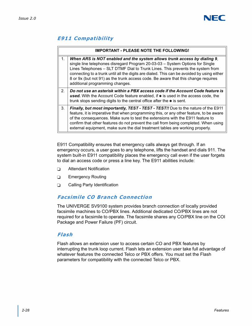
Issue 2.0
2-28 Features
E911 Compatibil ity
E911 Compatibility ensures that emergency calls always get through. If an emergency occurs, a user goes to any telephone, lifts the handset and dials 911. The system built-in E911 compatibility places the emergency call even if the user forgets to dial an access code or press a line key. The E911 abilities include:
Attendant Notification
Emergency Routing
Calling Party Identification
Facsimile CO Branch Connection
The UNIVERGE SV9100 system provides branch connection of locally provided facsimile machines to CO/PBX lines. Additional dedicated CO/PBX lines are not required for a facsimile to operate. The facsimile shares any CO/PBX line on the COI Package and Power Failure (PF) circuit.
Flash
Flash allows an extension user to access certain CO and PBX features by interrupting the trunk loop current. Flash lets an extension user take full advantage of whatever features the connected Telco or PBX offers. You must set the Flash parameters for compatibility with the connected Telco or PBX.
IMPORTANT - PLEASE NOTE THE FOLLOWING!
1. When ARS is NOT enabled and the system allows trunk access by dialing 9, single line telephones disregard Program 20-03-03 – System Options for Single Lines Telephones – SLT DTMF Dial to Trunk Lines. This prevents the system from connecting to a trunk until all the digits are dialed. This can be avoided by using either 8 or 9x (but not 91) as the trunk access code. Be aware that this change requires additional programming changes.
2. Do not use an asterisk within a PBX access code if the Account Code feature is used. With the Account Code feature enabled, if is used in the access code, the trunk stops sending digits to the central office after the is sent.
3. Finally, but most importantly, TEST - TEST - TEST!! Due to the nature of the E911 feature, it is imperative that when programming this, or any other feature, to be aware of the consequences. Make sure to test the extensions with the E911 feature to confirm that other features do not prevent the call from being completed. When using external equipment, make sure the dial treatment tables are working properly.
Issue 2.0
SV9100 General Description Manual 2-29
Flexible System Numbering
Flexible System Numbering lets you reassign the system port-to-extension assignments. This allows an employee to retain their extension number if they move to a different office. In addition, factory technicians can make comprehensive changes to your system number plan. You can have factory technicians:
Set the number of digits in internal (Intercom) functions. For example, extension numbers can have up to eight digits.
Change your system Service Code numbers.
Assign single digit access to selected Service Codes.
Talk to your sales representative to find out if this program is available to you.
You can also use Flexible System Numbering to change the system Trunk Group Routing code. Although the default code of 9 is suitable for most applications, you can alter the code if needed.
Flexible Timeouts
The Flexible Timeouts feature provides a variety of timers in the Resident System Program to allow the system to operate without initial programming. The system timers can be changed to meet customer needs according to the system application requirements.
Forced Trunk Disconnect
Forced Trunk Disconnect allows an extension user to disconnect (release) another extension active outside call. The user can then place a call on the released trunk. Forced Trunk Disconnect lets a user access a busy trunk in an emergency, when no other trunks are available. Maintenance technicians can also use Forced Trunk Disconnect to release a trunk on which there is no conversation. This can happen if a trunk does not properly disconnect when the outside party hangs up.
General Purpose Relay
The system allows up to eight general purpose relays using PGD(2)-U10 ADP’s (four relays per PGD unit) and one general purpose relay built into the GCD-CP10 for a maximum of nine relays. These relays are normally opened and can be closed by dialing an access code on any terminal or pressing a preprogrammed function key on any multiline terminal.
CAUTION
Forced Trunk Disconnect abruptly terminates the active call on the line. Only use this feature in an emergency and when no other line is available.
Issue 2.0
2-30 Features
The relays can then be set back to an open state by dialing an access code on any terminal or by pressing a preprogrammed function key on any multiline terminal. A relay can also be set back to an open state after a drive timer expires. Each relay can have a separate drive timer, when the relay is in a closed state, and this timer expires, the relay is automatically placed back into an open state.
Group Call Pickup
Group Call Pickup allows an extension user to answer a call ringing another extension in a Pickup Group. This permits co-workers in the same work area to easily answer others calls. The user can dial a code or press a programmed Group Call Pickup key to intercept the ringing call. If several extensions in the group are ringing at the same time, Group Call Pickup intercepts the call based on the extension priority in the Pickup Group.
With Group Call Pickup, a user can intercept the following calls:
A call ringing the user’s own pickup group
A call ringing another pickup group when the user knows the group number
A call ringing another pickup group when the user does not know the group number
There are 64 Call Pickup Groups available.
Group Listen
Group Listen permits a multiline terminal user to talk on the handset and have their voice broadcast over the telephone speaker. This lets the multiline terminal user’s co-workers listen to the conversation. Group Listen turns off the multiline terminal handsfree microphone so the caller does not pick the co-worker’s voices during a Group Listen.
Handset Mute
Handset Mute is provided to most terminals connected to the UNIVERGE SV9100 system. While talking on the multiline terminal handset, a station user can dial a feature code or press Mic to mute the transmit speech path. The station user can still hear the outside (or intercom) voice.
Handsfree and Monitor
Handsfree allows a multiline terminal user to process calls using the speaker and microphone in the telephone instead of the handset. Handsfree is a convenience for workers who do not have a free hand to pick up the handset. For example, a terminal operator could continue to enter data with both hands while talking on the telephone.
Three variations of Handsfree are available.
HandsfreeThe user can press Speaker to place and answer calls instead of using the handset.
Issue 2.0
SV9100 General Description Manual 2-31
Automatic HandsfreeThe user can press a trunk line key or virtual extension key without lifting the handset or pressing Speaker. An extension can have Automatic Handsfree for only outgoing calls or both outgoing and incoming calls.
MonitorUser can place a call without lifting the handset, but must lift the handset to speak.
Handsfree Answerback/Forced Intercom Ringing
Handsfree Answerback permits an extension user to respond to a voice-announced Intercom call by speaking toward the telephone, without lifting the handset. Like Handsfree, this is a convenience for workers who do not have a free hand to pick up the handset.
Headset Operation
A multiline terminal user can use a customer-provided headset in place of the handset. Like using Handsfree, using the headset frees up hands for other work. Headset Operation also provides privacy not available from Handsfree.
As the headset plugs into a separate jack on the bottom of the telephone, the handset can still be connected to the telephone. This provides an option to use the handset, headset or the speakerphone for calls.
Hold
Hold lets an extension user put a call in a temporary wait state. The caller on Hold hears silence or Music on Hold, not conversation in the extension user work area. While the call waits on Hold, the extension user may process calls or use a system feature. Calls left on Hold too long recall the extension that placed them on Hold.
There are four types of Hold:
System HoldAn outside call a user places on Hold flashes the line key (if programmed) at all other multiline terminals. Any multiline terminal user with the flashing line key can pick up the call.
Exclusive HoldWhen a user places a call on Exclusive Hold, only that user can pick up the call from Hold. The trunk appears busy to all other multiline terminals that have a key for the trunk. Exclusive hold is important if a user does not want a co-worker picking up their call on Hold.
Group HoldIf a user places a call on Group Hold, another user in the Department Group can dial a code to pick up the call. This lets members of a department easily pick up others calls.
Intercom HoldA user can place an Intercom call on Hold. The Intercom call on Hold does not indicate at any other extension.
Issue 2.0
2-32 Features
Hotel/Motel
Your UNIVERGE SV9100 telephone system provides Hotel/Motel services in addition to the many features available to business users. These Hotel/Motel services help you run your facility more efficiently, save you time and money, and provide your guests with more responsive service.
Hotel/Motel features include:
Wake Up Call/Snooze Callback
Single Digit Dialing
A Department Calling Group
Message Waiting
PMS Integration
Room to Room Calling Restriction
Toll Restriction (When Checked In)
Room Status
Room Status Printouts
DSS Console Monitoring
Do Not Disturb
Flexible Numbering Plan
Enhancements
With Version 3000 (3.00 or higher), guests have the ability to set Wake Up Call/Snooze Callback.
Hotline
Hotline gives a multiline terminal user one-button calling and Transfer to another extension (the Hotline partner). Hotline helps co-workers that work closely together. The Hotline partners can call or Transfer calls to each other by pressing a single key.
The Hotline feature has two applications.
Hotline (Hotline partner)
Ringdown Extension, Internal/External (Refer to Ringdown Extension, Internal/External on page 2-67.)
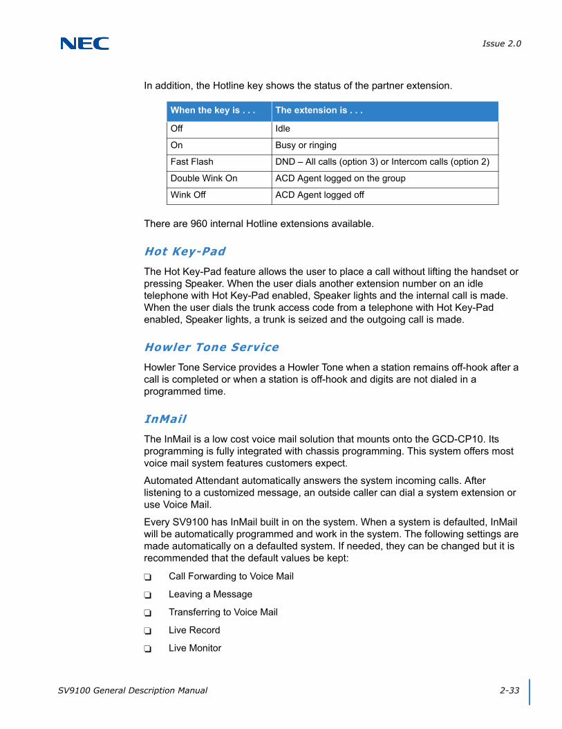
Issue 2.0
SV9100 General Description Manual 2-33
In addition, the Hotline key shows the status of the partner extension.
There are 960 internal Hotline extensions available.
Hot Key-Pad
The Hot Key-Pad feature allows the user to place a call without lifting the handset or pressing Speaker. When the user dials another extension number on an idle telephone with Hot Key-Pad enabled, Speaker lights and the internal call is made. When the user dials the trunk access code from a telephone with Hot Key-Pad enabled, Speaker lights, a trunk is seized and the outgoing call is made.
Howler Tone Service
Howler Tone Service provides a Howler Tone when a station remains off-hook after a call is completed or when a station is off-hook and digits are not dialed in a programmed time.
InMail
The InMail is a low cost voice mail solution that mounts onto the GCD-CP10. Its programming is fully integrated with chassis programming. This system offers most voice mail system features customers expect.
Automated Attendant automatically answers the system incoming calls. After listening to a customized message, an outside caller can dial a system extension or use Voice Mail.
Every SV9100 has InMail built in on the system. When a system is defaulted, InMail will be automatically programmed and work in the system. The following settings are made automatically on a defaulted system. If needed, they can be changed but it is recommended that the default values be kept:
Call Forwarding to Voice Mail
Leaving a Message
Transferring to Voice Mail
Live Record
Live Monitor
When the key is . . . The extension is . . .
Off Idle
On Busy or ringing
Fast Flash DND – All calls (option 3) or Intercom calls (option 2)
Double Wink On ACD Agent logged on the group
Wink Off ACD Agent logged off
Issue 2.0
2-34 Features
Personal Answering Machine Emulation
Voice Mail Overflow
Message Center Mailbox
Voice Mail Caller ID
Voice Mail Queuing
Message Key will Operate as Voice Mail Key
InMail Available
InMail: External Transfer Available
InMail: Softkey With Security Code Programming
InMail: Internal Message Notification Timer
InMail: Directory Dialing
InMail: Multiple Greetings
InMail: Message Playback Options
InMail – Automatic Access to VM by Caller ID
Before, when a user outside the system accessed their InMail mailbox, they dialed voice mail, then entered an access code followed by their mailbox number and password (if enabled). An InMail mailbox can be associated with a specific caller ID (CID) number. When the CID number is presented to the InMail it will automatically log the user into their mailbox. This enhancement improves VM accessibility for outside callers, allowing them to simply dial the main voice mail number and be automatically logged into their mailbox.
InMail – Cascade Message Notification
If an extension user receives a new message in their mailbox, Cascading Message Notification will call them at up to five preset destinations to let them know a new voice mail message has arrived. A destination can be an outside number (such as a cell phone, pager, or home office) or a co-worker's extension.
The Cascading Message Notification destinations are set up in the Notification Schedule. Each of the five schedule entries can be individually enabled or disabled and provides options for:
Type: Voice call or pager.
Start Hour: The time the destinations become active.
End Hour: The time the destinations become inactive.
Number: The destination telephone, pager, or extension number.
Busy Attempts: The number of times the system will try the destination when it is busy. The system cancels notification callouts for this entry when the Busy Attempts number is met.
Issue 2.0
SV9100 General Description Manual 2-35
RNA Attempts: The number of times the system will try the destination when it is unanswered. The system cancels notification callouts for this entry when the RNA Attempts number is met.
Security: Enables or disables the Security Code requirement for the notification destinations. For example, you may want to disable the Security Code when the destinations is your cell phone and it may be inconvenient to dial digits after answering the notification callout.
When the extension user enables Cascading Message Notification, the system will try each enabled destination that is active for the current day and time (i.e., in-schedule). The system will not try any destinations that are disabled or are not in-schedule. When the retries for a particular destination have been met the system will immediately move to the next destination.
With SV9100 software, each mailbox can be set to queue notification options. When this feature is enabled, messages received when destinations are not in-schedule are queued until a destination is in-schedule at which time the notification process will start.
InMail – Email Notification
Email Notification automatically sends an email notification when a Subscriber Mailbox receives a new message. The email can optionally include the recorded message as a wav file attachment. To hear the message, the email recipient double-clicks the wav attachment to have the message play in their wav player (such as Windows Media Player).
Email Notification uses SMTP (Simple Mail Transfer Protocol) to deliver messages to the recipient’s email account. If the message recipient has a mobile telephone service provider with an SMS (Short Message Service) portal, they can optionally choose to have text messages delivered right to their cell phone. In either case, Email Notification does not provide synchronization – the email account and the voice mailbox operate independently. For example, deleting the voice mail message does not automatically delete the email and visa-versa.
If Email Notification tries to deliver an email and it doesn’t go through because of a connection problem (i.e., no connection or a dropped connection), it will retry every 15 minutes for 24 hours. If the email still can’t go through, Email Notification cancels the delivery. Email deliveries that fail because authentication fails or the encryption mode is incorrect are immediately cancelled.
InMail – Find-Me Follow-Me
Find-Me Follow-Me helps an Automated Attendant caller locate an extension user who is not at their desk. If their call is unanswered and is picked up by voice mail, the caller has the option of dialing a digit to try up to three alternate Find-Me Follow-Me destinations. A destination can be an outside number (such as a cell phone or home office) or a co-worker's extension.
Issue 2.0
2-36 Features
The Find-Me Follow-Me destinations are set up in the Notification Schedule. Each of the three entries can be individually enabled or disabled and provides options for:
Start Hour: Time the destinations become active.
End Hour: Time the destinations become inactive.
Number: The destination telephone, pager or extension number.
Days of Week: Days of the week the destinations are active or inactive.
If the caller chooses the Find-Me Follow-Me option, the system will try each enabled entry that is active for the current date and time (i.e., in-schedule). The system will not try any entries that are disabled or are not in-schedule.
When trying the destinations, Find-Me Follow-Me skips an active, in-schedule number that is busy, in DND, or is unanswered. When all active in-schedule destinations have been tried the caller can then choose to try Find-Me Follow-Me again or select another option.
You can set up Find-Me Follow-Me for an extension in system programming. In addition, an extension user can set up Find-Me Follow-Me from their Mailbox Options.
InMail – Language Setting
The Language setting feature allows the telephone display language and the InMail mailbox language to be changed from the telephone. This can be used to change either the user’s phone or another specified telephones display and InMail language if allowed in system programming. Either a dial access code or Softkey operation is available.
InMail – Park and Page
InMail Park and Page can automatically Park a call at an extension and Page the user with a prerecorded Paging Message announcing the parked call. The called extension user can then go to any telephone and implement Personal Park to pick up the call. With InMail Park and Page, InMail tries to locate the person instead of just sending the call to their mailbox. Additionally, there is no need for an operator or receptionist to manually answer the call, park it, and then try to track down the employee.
The Paging Message is usually recorded in the user’s own voice and typically says something like, “Mike Smart, you have a call.” If the Paging Message is not recorded for the extension, a built-in message announces the called party’s name or extension number (if the name is not recorded).
InMail Park and Page is available for all types of trunk calls that are redirected to voice mail via forwarding or overflow, including transferred calls, Direct Inward Lines, and Direct Inward Dialing. Park and Page is also available for Automated Attendant Screened (STRF) and Unscreened (UTRF) Transfers. Optionally, an extension can have calls from the Automated Attendant immediately Park and Page without trying their extension first.
Issue 2.0
SV9100 General Description Manual 2-37
When InMail Park and Page intercepts the call, it normally offers the caller four options:
1. Dial 1 to leave a message in the called extension’s mailbox.(The caller hears the mailbox greeting, if recorded.)
2. Dial 2 to Park and Page.(The caller returns to these options if the Park is not picked up.)
3. Dial 3 to have the system try and locate this person.(The Find-Me Follow-Me feature returns the caller to these options if the user is not located.)
4. Dial 4 for other options.(Normally, this routes to the extensions Next Call Routing Mailbox).
InMail Park and Page is available at Personal and Group Subscriber Mailboxes, and can be enabled through system programming or via the subscriber’s Mailbox Options Menu. InMail Park and Page is not applicable to Intercom calls.
Automated Attendant Direct to Voice Mail (DVM)
When an extension has Automated Attendant Direct to Voice Mail (DVM) enabled, all calls from the Automated Attendant go directly to the subscriber’s mailbox. The extension does not ring for Automated Attendant calls. The caller hears the mailbox greeting and can leave a message, but unlike Park and Page is not normally offered any other routing options. A subscriber typically turns on DVM when they need to work at their desk undisturbed by outside calls from the Automated Attendant.
DVM can be enabled by the installer from system programming or by the extension user from their Mailbox Options Menu.
Keep in mind that DVM does not block Intercom calls from co-workers or any other type of outside call not routed through the Automated Attendant.
InMail – Upload Download Audio
The InMail Upload Download Audio feature allows the upload of mailbox greetings up to 1MB in size, recorded on a PC or professionally, to any valid subscriber mailbox in the system. It also allows users to listen to, download and/or delete voice mail messages from callers. Access to the InMail compact flash drive is via the HTML User Pro (Web Pro).
Instant Access Application (IAA)
The Instant Access Application (IAA) feature is a server based XML application that allows NEC IP display phones (DT710/DT730/DT730G/DT750/DT830 and DT830G) access to the following options and features:
Voice Mail
Speed Dial
News (RSS News)
Issue 2.0
2-38 Features
Weather
Photo
RSS Photo
Calendar
Banner
Sub Banner text
Screen Saver
Icon Position
Mascot Greeting
Widget
Intercom
Intercom gives extension users access to other extensions. This provides the system with complete internal calling ability.
Handsfree Answerback/Forced Intercom Ringing
Handsfree Answerback permits an extension user to respond to a voice-announced Intercom call by speaking toward the telephone, without lifting the handset. Like Handsfree, this is a convenience for workers who do not have a free hand to pick up the handset.
Busy Status Display
When a display multiline terminal user places an Intercom call to a busy extension, the details of the busy status (who is talking to the extension or which line is in use by the extension) can be displayed. The details of the trunk busy status (the extension using the line) can be displayed after trying to access the trunk. This feature provides a user information which can determine whether or not they should use Barge-In for the extension or trunk. This information automatically displays for a multiline terminal when programmed.
IP Multil ine Station (SIP)
The UNIVERGE SV9100 system supports IP extensions using a variety of multiline terminals. These telephones have the same look and functionality of typical multiline telephones, but they are connected to the CCPU via IP rather than by a hardwired connection to a DLC port.
The following DT700 IP Multiline Telephones (ITL) support IP extensions:
ITL-2E-1 (BK) TEL
ITL-6DE-1 (BK) TEL
ITL-8LDE-1 (BK) TEL
Issue 2.0
SV9100 General Description Manual 2-39
ITL-8LD-1 (BK) TEL/ITL-8LD-1 (WH) TEL
ITL-12D-1 (BK) TEL/ITL-12D-1 (WH) TEL
ITL-12CG-3 (BK) TEL
ITL-12DG-3 (BK) TEL
ITL-12PA-1 (BK) TEL
ITL-24D-1 (BK) TEL/ITL-24D-1 (WH) TEL
ITL-32D-1 (BK) TEL/ITL-32D-1 (WH) TEL
ITL-320C-1 (BK) TEL/ITL-320C-2 (BK) TEL
The following DT800 IP Multiline Telephones (ITZ) support IP extensions:
ITZ-8LD-3 (BK) TEL
ITZ-8LDG-3 (BK) TEL/ITZ-8LDG-3 (WH) TEL
ITZ-12D-3 (BK) TEL/ITZ-12D-3 (WH) TEL
ITZ-12CG-3 (BK) TEL/ITZ-12CG-3 (WH) TEL
ITZ-12DG-3 (BK) TEL/ITZ-12DG-3 (WH) TEL
ITZ-24D-3 (BK) TEL/ITZ-24D-3 (WH) TEL
NAPT Traversal
NAPT (Network Address Port Translation), is a method by which a private address or addresses and their TCP/UDP ports are translated into a single public address and its TCP/UDP ports. The NAPT feature gives the SV9100 the ability to “traverse” its own subnet. With NAPT, the network administrator can place the GCD-CP10 and the GPZ-IPLE (VoIPDB) in the customers LAN while still making it accessible to users outside the local LAN. The NAPT Feature also allows the IP terminals to be placed in a local LAN in a remote network and be able to communicate back to the SV9100.
IP Multil ine Station (SIP) – ML440 Cordless
Many SMB businesses, understanding the impact of a mobile workforce, are rapidly defining their requirements for enabling effective communications and information access for mobile users. SMB Mobility will allow the individual staff member to be instantly accessible- thus becoming more productive.
The ML440 IP Wireless Handset is an ergonomically designed compact wireless handset for business users who are mobile in the office and want to make and receive wireless calls while in the office. The DECT protocol operates in the 1.9 GHZ frequency band that has been cleared specifically for voice applications, thus avoiding any interference problems and delivering crystal clear and secure voice conversations.
Issue 2.0
2-40 Features
The ML440 provides numerous features and conveniences for optimal comfort. Its illuminated graphic color LCD display enables use in poorly lit environments, while its internal loudspeaker provides Handsfree operation with excellent sound quality. Powerful encryption techniques ensure secure communication, and it can also provide the subscriber with most of the features available for a wired phone, in addition to its roaming and handover capabilities.
IP Multil ine Station (SIP) – ML440/G566/G266 with AP400/AP300
ML440:
Many SMB businesses, understanding the impact of a mobile workforce, are rapidly defining their requirements for enabling effective communications and information access for mobile users. SMB Mobility will allow the individual staff member to be instantly accessible thus becoming more productive.
The ML440 IP Wireless Handset is an ergonomically designed compact wireless handset for business users who are mobile in the office and want to make and receive wireless calls while in the office. The DECT protocol operates in the 1.9 GHZ frequency band that has been cleared specifically for voice applications, thus avoiding any interference problems and delivering crystal clear and secure voice conversations.
The ML440 provides numerous features and conveniences for optimal comfort. Its illuminated graphic color LCD display enables use in poorly lit environments, while its internal loudspeaker provides handsfree operation with excellent sound quality. Powerful encryption techniques ensure secure communication, and it can also provide the subscriber with most of the features available for a wired phone, in addition to its roaming and handover capabilities.
Unlike other in-building wireless solutions for the SV9100, the ML440 is an integrated multiline handset capable of supporting the key elements of a SMB mobile solution. A complete list of supported features can be found below.
The ML440 has two sets of keys:
Three softkeys that are dedicated depending on the state of the call and four programmable keys. The three dedicated softkeys are predefined depending on the state of the call. For example once a person is in conversation, these three keys are Hold / Conf./ Transfer. This makes it easy for end users to receive and move calls around.
Four programmable keys on the base on the handset. The keys can be programmed for many of the same features that are supported on the DT700/DT800 desk sets.
Line key programming is flexible. The following is an example for the first three programmable keys:
Line Keys 1 and 2 = CAP Keys
Line Key 3 = Intercom Key
Issue 2.0
SV9100 General Description Manual 2-41
G566 andG266:
The G566 and G266 operate as standard SIP devices when connected to a SV9100. The line keys on the G566 are not functional in this application.
Powering the AP400/AP300
The AP400/AP300 can only be powered using Power over Ethernet (PoE) 802.3af. A PoE switch is a switched hub that also provides power over the spare pairs. The switch can be used with other devices than the IP telephones and detects whether or not power is needed. Using a PoE switch makes it easier to protect the IP telephones from loss of power (connection of the PoE switch to an UPS).
Updating the AP400 and ML440/G566/G266 System Firmware
The firmware on base stations and handsets is updated remotely using the HTTP configuration interface to download firmware files from a TFTP server. Updating base station firmware involves an automatic reboot of the base station at the end of the firmware download. This will drop any active calls and in addition updating the handset firmware can take several hours. It is recommended updates are performed after normal business hours.
IP Multil ine Telephone (UT880)
The UT880 is a VoIP desk phone that runs the UT880 MLT Multiline Telephone Application for use on the SV9100 system. This phone is powered by Power over Ethernet (PoE) reducing the need for power adapters allowing for a clean installation. In addition, for those users who frequently make long calls the UT880 provides headset support for added comfort.
The UT880 can only be powered using Power over Ethernet (PoE) 802.3af.
IP Single Line Telephone (SIP)
SIP (Session Initiation Protocol) is used for Voice over Internet Protocol. It is defined by the IETF (Internet Engineering Task Force) RFC3261. Other RFC designations, such as RFC3842, refer to a later implementation of SIP and may be supported by the UNIVERGE SV9100. Commonly called SIP Station, this feature is used for IP Stations using SIP.
SIP analyzes requests from clients and retrieves responses from servers, then sets call parameters at either end of the communication, handles call transfer, and terminates. Typically, such features, including but not limited to Voice over IP services, are available from an SIP service provider.
REFERENCE
Refer to the UNIVERGE SV9100 IP-DECT Customer Engineer Manual for additional information.
Issue 2.0
2-42 Features
Enhancements
With Version 2000 (2.00 or higher), Conference is supported on Standard SIP terminals.
STD SIP – TCP Connection Support
With Version 3000 CPU software or higher, the SV9100 supports TCP connection of standard SIP telephones.
VoIP and CPU LAN Link – Speed and Duplex Mode
With Version 3000 CPU software or higher, the SV9100 provides the information for the CPU and GPZ-IPLE LAN link speed and Duplex mode.
STD SIP Transfer–Unattended
With SV9100 software, any standard SIP terminal can perform an Unattended (Blind/Unsupervised) transfer.
STD SIP Conference
With SV9100 2.00 or higher software, Standard SIP Terminals can initiate a conference call.
IP Single Line Telephone (SIP) – NAT Mode
With SV9100 system software, the SV9100 supports the NAT (Network Address Translation) mode for Standard SIP terminals.
IP Trunk – H.323
H.323 is an International Telecommunication Union (ITU) standard for Packet Based Multimedia Communication Systems. The UNIVERGE SV9100 can use H.323 to connect to another UNIVERGE SV9100 system or a third-party product.
The feature set is limited. When using H.323, it is impossible to use the advanced networking features. If these features are required, use IP KCCIS. The UNIVERGE SV9100 Voice over IP Trunk – H.323 package sends the real-time voice over the corporate LAN or WAN. The voice from the telephone is digitized and then put into frames to be sent over a network using Internet Protocol.
The UNIVERGE SV9100 Voice over IP Trunk – H.323 package allows communication using standard H.323 (Normal and Fast Start) Protocol and allows connectivity to any H.323 standards compliant voice gateway and gatekeeper. This VoIP Trunk Daughter board also allows Registration and Authentication Server (RAS) support to register with an RAS Server and use Gatekeeper for dynamic call routing.
The GPZ-IPLE – H.323 is an optional interface that can provide IP trunks and Tie Lines. It can operate in the following modes:
COI
Issue 2.0
SV9100 General Description Manual 2-43
COID
DID
TLI
DTI
Depending on the requirements and resource allocation in the LAN/WAN/Internet, the GPZ-IPLE – H.323 can be configured to use any of the following voice compressions:
G.729 Low bandwidth requirement is used on most Wide Area Network links.
G.711 High bandwidth requirement is usually used on Local Area Networks.
G 722 This Codec is useful in fixed network, Voice over IP applications, where the required bandwidth is typically not prohibitive.
IP Trunk – (SIP) Session Initiation Protocol
The UNIVERGE SV9100 IP Trunk SIP package sends the real time voice over the corporate LAN or WAN. The voice from the telephone is digitized and then put into frames to be sent over a network using Internet protocol.
Using VoIP equipment at a gateway (a network point that acts as an entrance to another network), the packetized voice transmissions from users in the company are received and routed to other parts of the company Intranet (local area or wide area network) or they can be sent over the Internet using CO lines to another gateway.
The GPZ-IPLE Daughter Board interface can provide IP trunks and Tie Lines that can operate in the following modes:
COI
COID
DID
TLI
DTI
SIP Trunk E.164 Support
With SIP Trunk E.164 Support enabled, the PBX is able to support SIP configurations where the number presentation within the SIP messages is formatted using the E.164 international numbering scheme. Specifically the system is able to handle the + digit when required as the International Access Code.
Issue 2.0
2-44 Features
SIP Trunk E.164 CLIP Enhancement
With the SIP Trunk E.164 CLIP Enhancement enabled, when an incoming SIP call from an external ITSP is presented at the system with a + in the From header field as the international access code, it is recognized and displayed as an international call at the terminal display and also logged in the terminals incoming caller history, allowing any outbound calls made from a multiline terminals caller history possible using this numbering scheme.
This presentation can be a requirement of certain SIP ITSPs (Internet Telephony Service Providers) so it is necessary the PBX can handle these calls and modify any SIP messages to the correct format accordingly.
Video Support over SIP Trunk
The SV9100 can support video calling over SIP interconnection trunks. IP Trunk License (5001), IP Terminal License (5111), SIP Video License (0040), System Port License (0300) and Version R3 License (0413) are required.
SIP Trunk – Fax Pass-Through
The SV9100 supports SIP trunk Fax pass-through using either the T.38 relay or Pass-Through mode. If the SIP Carrier supports a T.38 Fax relay, select the T.38 mode. If the SIP carrier does not support T.38 Fax relay, then select the Pass-Through mode. The type of Fax relay should be selected manually as per the SIP carrier capability.
SIP Trunk Keep Alive using OPTION message
The SV9100 provides support for SIP Trunk Keep Alive using the OPTION message for all six SIP Profiles, applicable to both IP System Interconnection and SIP Carrier mode.
IP Video Doorphone
The IP Video Doorphone (IP3NE-IPCDH) can be connected to SV9100 system through a PoE Data Switch and is normally used to monitor an entrance door. When pressed, the Doorphone sends a chime tone to all extensions programmed to receive the chime. To answer, the called extension user just lifts the handset. This lets the extension user talk to the visitor at the Doorphone location. In addition, a user can view the outside image using the DR-viewer application (installed on a PC in the same network) or the image can be viewed using a Polycom IP VVX 1500 terminal.
Each Doorphone has a Normally Opened and a Normal Closed relay contact that can be used to connect to the electric door strike. These contacts are used to remotely control the entrance door. After answering the chimes, a Multiline Terminal user can press the Recall key and activate the Doorphone contacts. This in turn releases the electric strike on the entrance door.
Issue 2.0
SV9100 General Description Manual 2-45
IP/Digital Call Logging
When using NEC DT300 and DT700 desktop terminals, telephone calls can be monitored, recorded and stored. For single phone applications, the NEC 1-Port Digital Call Logging Unit can be used. This will only support digital DT300 phone applications. For up to 16 digital ports or VoIP traffic the NEC IP/Digital Back Office call logging unit can be used.
The back bone of NEC’s higher volume call recording software is the NEC IP/Digital BackOffice software which is PC based and is capable of recording calls from both VoIP (DT700) and digital (DT300) phones. NEC’s BackOffice software works in conjunction with a 4-Port Digital Logging Unit for recording of TDM type calls.
IP Tap or BackOffice is used to record IP type calls. IP Tap is installed in line with the IP terminal. BackOffice relies on port mirroring to collect and process packets for the recording of IP type calls.
Three options are available for playing back of the recorded calls. For playback and management of recorded calls NEC offers the NEC Player/Recorder, Manager and Reporter Pro. All of these perform the playback function but offer increasing levels of additional features.
The NEC Call Logging Unit now supports licensing via LMS which in most cases can eliminate the need for a license dongle.
XML Call Recording Control (IP Terminals Only)
IP/Digital BackOffice Version 3.0 has been enhanced to allow for Desk Top Control support for DT700 terminals only. This feature allows the user to Start, Stop or Pause the recording function and to make recorded comments from the terminal. Management of recordings can be done with IP/Digital Manager and Reporter Pro.
ISDN Compatibil ity
ISDN-BRI
Integrated Service Digital Network – Basic Rate Interface (ISDN-BRI) is a Public Switched Telephone Network (PSTN) service that provides two B channels and a D channel (2B + D) for voice call trunking. The B channels provide two voice path connections. Caller ID is usually a standard feature on ISDN-BRI provided trunks.
CAUTION
The use of monitoring, recording, or listening devices to eavesdrop, monitor, retrieve, or record telephone conversation or other sound activities, whether or not contemporaneous with transmission, may be illegal in certain circumstances under federal or state laws. Legal advice should be sought prior to implementing any practice that monitors or records any telephone conversation. Some federal and state laws require some form of notification to all parties to a telephone conversation, such as using a beep tone or other notification methods or requiring the consent of all parties to the telephone conversation, prior to monitoring or recording the telephone conversation. Some of these laws incorporate strict penalties.
Issue 2.0
2-46 Features
Caller ID indication displays the calling party telephone number on the LCD of the multiline terminal for CO incoming calls. This interface provides voice communication path only.
With ISDN BRI the SV9100 only supports the following protocol:
National ISDN-1 (NI-1)
ISDN-PRI
ISDN-PRI (Integrated Service Digital Network – Primary Rate Interface) is a Public Switched Telephone Network (PSTN) service that provides 23 B channels and a single D channel (23B+1D) for trunking. The UNIVERGE SV9100 supports it. Caller ID indication displays the calling party telephone number on the LCD of the multiline terminal for CO incoming calls. This interface provides voice communication path only.
With ISDN PRI the SV9100 supports the following protocols:
NI-2
4ESS (AT&T Custom)
AT&T 5ESS (Lucent Custom)
DMS-100 Custom (Nortel Spec NIX-A211-1)
DMS-100 National ISDN (Nortel Spec NIX-A233-1)
ISDN – BRI/PRI Features
DID Line Service
Calling Line Identification Presentation (CLIP)
Calling Party Number (CPN) Presentation from Station
Calling Party Name
SMDR Includes Dialed Number
Display Shows Why Caller ID is Not Available
ISDN 2 B-Channel Transfer
The ISDN PRI 2 B-Channel Transfer feature allows the UNIVERGE SV9100 to receive a call on one B-Channel and transfer it back out on a second B-Channel (Trunk-to-Trunk transfer on the telco side). When the transferred call connects, both of the B-Channels are then released and available for either making or receiving another call. This feature provides more efficient use of B Channels on an ISDN PRI by allowing a customer to transfer calls without tying up their B Channels for the duration of the call.
Issue 2.0
SV9100 General Description Manual 2-47
IVR – Appointment Reminder Server
The IVR – Appointment Reminder Server solution is designed to provide a knowledge-based, intelligent distributed application to optimize the scheduling and reminder of appointments. The IVR – Appointment Reminder Server is an external software application that connects to the SV9100 through Standard SIP Ports. The IVR – Appointment Reminder Server can be configured for 8 – 16 ports using SV9100 licensing.
This IVR – Appointment Reminder Server enables the phone system to automatically call customers and remind them of their upcoming appointment. The Appointment Reminder automatically dials based on a configurable schedule and upon detection of a “live voice” or answering device, delivers one of your pre-recorded messages. The customer is then provided options to confirm the appointment or, if they desire, to be able to talk to a customer service representative.
The Appointment Reminder was designed for the following verticals:
Dentist office
Doctor’s office
Optometrist’s office and other medical offices where scheduling is in common use.
Any other office where appointments are made and need to be reminded.
IVR – Broadcast Server
The IVR – Broadcast Server solution is designed to provide a knowledge based, intelligent distributed application which provides the most cost effective form of contacting your customers, employees, and prospects. The IVR – Broadcast Server is an external software application that connects to the SV9100 through Standard SIP Ports. The IVR – Broadcast Server can be configured for 8 – 16 ports using SV9100 licensing. Each IVR – Broadcast Server port requires the following license in the SV9100: SV9100 IP Client (STD/MLT)-Lic-1 (e.g. For 16 ports of Broadcast Server (16) SV9100 IP Client (STD/MLT)-Lic-1 must be purchased.)
This solution provides an effective way of communicating corporate voice messages, informational messages, past due notices, reminders, and verifications. The IVR – Broadcast Message solution is designed to call numbers from a managed list and plays a pre-recorded message to the call recipient or answering machine.
Broadcast was designed for the following verticals:
Medical Offices
Utility Companies
Emergency Centers
Any other office where messages are to be Broadcast to users.
Issue 2.0
2-48 Features
K-CCIS – Call Rerouting
The CCIS Call Rerouting feature allows a system to use multiple call routing priorities when remote system trunks are all busy. The four priorities can be local or remote trunks. For example using ARS and F-Route table priorities the system can try up to four remote systems or up to three remote systems and a local trunk to route the outbound call to its destination. If an outbound route is unavailable for any reason the call will fall through to the next priority.
K-CCIS – IP
The system uses the GPZ-IPLE daughter board to connect multiple systems together over a Data Communication IP Network (Intranet). Key-Common Channel Interoffice Signaling (KCCIS) is used to provide telephony services between the UNIVERGE SV9100 and another UNIVERGE SV9100 or a NEAX PBX system.
CCIS Networking via IP (Non Peer-to-Peer Connections Basis).
IP trunk connections over CCIS Networking via IP provide telephony services between UNIVERGE SV9100 and UNIVERGE SV9100 and a NEAX IPS, IPX, SV7000, UNIVERGE SV8100, UNIVERGE SV8300 and UNIVERGE SV8500.
The UNIVERGE SV9100 uses the NEC proprietary CCIS Peer to Peer protocol over IP to communicate between system to system.
The GPZ-IPLE is required for connections between IP terminals and IP trunks. Only one GPZ-IPLE daughter board can be accommodated per system with a maximum of 128 DSP resources per system.
The GPZ-IPLE daughter board is an optional interface package for converting the Real Time Transfer Protocol (RTP) packets on the IP network to PCM highway. IP telephones are required to be connected directly to the IP bus. When IP telephones are required to be connected to conventional PCM based digital circuit, the GPZ-IPLE converts IP packet signals. The GPZ-IPLE provides the digital signal processors (DSPs) for IP stations and trunks.
A DSP provides format conversion from circuit switched networks (TDM) to packet switched networks (IP). Each voice channel from the circuit switched network is compressed and packetized for transmission over the packet network. In the reverse direction, each packet is buffered for de-jittering, decompressed, and sent to the circuit switched network. Each DSP converts a single speech channel from IP to TDM and vice versa.
CCIS Networking via IP (Peer-to-Peer Connections Basis)
IP-KCCIS has been improved to support Peer-to-Peer calls between IP Terminals residing in different offices, without using DSP resources.
Issue 2.0
SV9100 General Description Manual 2-49
K-CCIS – IP with PVA
The K-CCIS – IP with PVA feature provides the benefits and additional feature compatibility of Key-Common Channel Interoffice Signaling (K-CCIS) between multiple systems including NEAX PBX systems connected together over a Data Communication IP Network (Intranet). Voice Signals and common signaling from and to distant offices are converted into IP packets and transmitted through the Data IP Network. When using this feature, both Voice and Data Communication lines are integrated into one network and communication costs can be reduced.
This feature is available between UNIVERGE SV9100, UNIVERGE SV8100 and NEAX PBX systems.
The following features are provided:
Automatic Recall
Brokerage Hotline
Call Forwarding – All Calls
Call Forwarding – Busy/No Answer
Call Park Retrieve
Call Transfer – All Calls
Calling Name Display
Calling Number Display
Calling Party Number (CPN) Presentation from Station
Centralized Billing
Centralized BLF (K-CCIS)
Centralized Day/Night Mode Change
Centralized E911
Dial Access to Attendant
Direct Inward Dialing
Dual Hold
Elapsed Time Display
Flexible Numbering of Stations
Hands-Free Answerback
Hot Line
Link Reconnect
Multiple Call Forwarding – All Calls
Multiple Call Forwarding – Busy/No Answer
Paging Access
Issue 2.0
2-50 Features
Quick Transfer to Voice Mail
Station-to-Station Calling
Uniform Numbering Plan
Voice Call
Voice Mail Integration
Not supported with NEAX PBX.
K-CCIS – T1
Key-Common Channel Interoffice Signaling (K-CCIS) allows multiple systems to be connected to provide additional feature compatibility, above what normal Tie Lines provide. The system is configured with a 24 channel T1 Connection and GCD-CCTA for receiving or transmitting common signaling data from/to a distant office. The system can provide a variety of interoffice service features such as Calling Name display, Centralized Voice Mail Integration, or Link Reconnect.
The following features are provided:
Call Forwarding – All Calls – K-CCIS
Call Forwarding – Busy/No Answer – K-CCIS
Call Park Retrieve – K-CCIS
Call Transfer – All Calls – K-CCIS
Calling Name Display – K-CCIS
Calling Number Display – K-CCIS
Calling Party Number (CPN) Presentation from Station – K-CCIS
Centralized Billing – K-CCIS
Centralized BLF (K-CCIS)
Centralized Day/Night Mode Change – K-CCIS
Centralized E911 (K-CCIS)
Dial Access to Attendant – K-CCIS
Direct Inward Dialing – K-CCIS
Dual Hold – K-CCIS
Elapsed Time Display – K-CCIS
Flexible Numbering of Stations – K-CCIS
Hands-Free Answerback – K-CCIS
Hot Line – K-CCIS
IP (K-CCIS)
IP (K-CCIS) to NEAX (Point-to-Multipoint)
Issue 2.0
SV9100 General Description Manual 2-51
Link Reconnect – K-CCIS
Multiple Call Forwarding – All Calls – K-CCIS
Multiple Call Forwarding – Busy/No Answer – K-CCIS
Paging Access – K-CCIS
Quick Transfer to Voice Mail – K-CCIS
Station-to-Station Calling – K-CCIS
Uniform Numbering Plan – K-CCIS
Voice Call – K-CCIS
Voice Mail Integration – K-CCIS
Not supported with InMail.
Last Number Redial
Last Number Redial allows an extension user to quickly redial the last number dialed. For example, a user may quickly recall a busy or unanswered number without manually dialing the digits.
Last Number Redial saves the last 24 digits a user dials in system memory. The number can be any combination of digits 0~9, # and . The system remembers the digits regardless of whether the call was answered, unanswered or busy. The system normally uses the same trunk group as for the initial call. However, the extension user can preselect a specific trunk if desired.
When the Redial key is pressed, the display indicates REDIAL [#] / SYS. The user can then press # to redial the number displayed, or enter a System Speed Dialing bin number to be dialed. Pressing Redial repeatedly scrolls through the last 10 numbers dialed.
Licensing
Licenses are used to activate certain features and applications for the UNIVERGE SV9100. Refer to the UNIVERGE SV9100 Features and Specifications Manual for more details.
Temporary License
Temporary License activates all valid feature licenses and all port maximum licenses. Temporary License is programmed using Telephone programming only. Web/PC pro can be used when verifying the settings.
The Temporary License can be set up to a maximum number of 10 days.
Issue 2.0
2-52 Features
Line Load Control
The Line Load Control feature allows the system to be configured so that resource use is limited to certain stations during very high system load conditions. This allows only high priority phone access to phone system resources during very high CPU load conditions.
If enabled, when the configured low level threshold is reached the system will not allow restricted phones to make or receive internal or external calls. Calls that are in progress are not affected, but when a phone set to be restricted hangs up they will not be able to make or receive calls until the configure threshold to release restriction is reached.
Line Preference
Line Preference determines how a multiline terminal user places and answers calls. There are two types of Line Preference: Incoming Line Preference and Outgoing Line Preference.
Incoming Line Preference
Incoming Line Preference establishes how a multiline terminal user answers calls. When a call rings the multiline terminal, lifting the handset answers either the ringing call (for Ringing Line Preference) or seizes an idle line (for Idle Line Preference). The idle line can provide either Intercom or trunk dial tone (see Outgoing Line Preference below). Ringing Line Preference helps users whose primary function is to answer calls (such as a receptionist). Idle Line Preference is an aid to users whose primary function is to place calls (such as a telemarketer).
Outgoing Line Preference
Outgoing Line Preference sets how a multiline terminal user places calls. If a multiline terminal has Outgoing Intercom Line Preference, the user hears Intercom dial tone when the handset is lifted. If a multiline terminal has Outgoing Trunk Line Preference, the user hears trunk dial tone when the handset is lifted. Outgoing Line Preference also determines what happens at extensions with Idle Line Preference. The user hears either trunk (dial 9) or Intercom dial tone.
Auto-Answer of Non-Ringing Lines
With Auto-Answer of Non-Ringing Lines, an extension user can automatically answer trunk calls that ring other extensions (not their own). This helps a user that has to answer calls for co-workers that are away from their desks. When the user lifts the handset, they automatically answer the ringing calls based on Trunk Group Routing programming. The extension user ringing calls, however, always have priority over calls ringing co-worker extensions.
Issue 2.0
SV9100 General Description Manual 2-53
Long Conversation Cutoff
For incoming and outgoing central office calls, each trunk can be programmed to disconnect after a defined time. The time begins when the trunk is seized and disconnects the call after the time expires.
When used with the Warning Tone for Long Conversation feature, the system can provide a warning tone on outgoing trunks calls before the call is disconnected.
Loop Keys
Loop Keys are uniquely programmed function keys that simplify placing and answering trunk calls. There are three types of Loop Keys: Incoming Only, Outgoing Only and Both Ways.
Incoming Only loop keys – answering trunk calls
Outgoing Only loop keys – placing trunk calls
Both Ways loop keys – combine the functions of both Incoming Only and Outgoing Only loop keys
Maintenance
The UNIVERGE SV9100 system has several utilities to assist in troubleshooting and diagnosing problems both during and after installation.
PCPro can remotely access the UNIVERGE SV9100 for maintenance and diagnostics. Within PCPro, the debug terminal can be accessed to monitor the systems activity and logging. PCPro also has built-in reports that can display alarm data. If need be, an option in PCPro allows the technician to reset or initialize the system remotely. If the technician determines the problem is isolated to a specific slot, PCPro can reset only the slot in question.
The SV9100 Maintenance manual contains a number of flow charts to help technicians diagnose and resolve problems that may arise during and after the installation of the UNIVERGE SV9100 system.
Side Tone Auto Setup
Per each analog trunk (or all analog trunks) the most suitable Codec Filter setting for Program 81-07 and Program 81-17 can be automatically adjusted using Programs 90-68-01 and 90-68-02.
Meet Me Conference
With Meet Me Conference, an extension user can set up a Conference with their current call and up to 31 other internal or external parties. Each party joins the Conference by dialing a Meet Me Conference code. Meet Me Conference lets extension users have a telephone meeting – without leaving the office.
Issue 2.0
2-54 Features
The GCD-CP10 provides two blocks of 32 conference circuits (or three blocks of 32 conference circuits when the modem function is not used), allowing each block to have any number of internal or external parties conferenced up to the block limit of 32.
Meet Me Paging
Meet Me Paging allows an extension user to Page a co-worker and privately meet with them on a Page zone. The Paging zone is busy to other users while the meeting takes place. While the co-workers meet on the zone, no one else can hear the conversation, join in, or make an announcement using that zone. Meet Me Paging is a good way to talk to a co-worker when their location is unknown. If the co-worker can hear the Page, they can join in the conversation.
Meet Me Paging Transfer
If a user wants to Transfer a call to a co-worker but does not know where the co-worker is, they can use Meet Me Paging Transfer. With Meet Me Paging Transfer, the user can Page the co-worker and have the call automatically Transfer when the co-worker answers the Page. Since Meet Me Paging Transfer works with both Internal and External Paging, a call can be quickly extended to a co-worker anywhere in the facility.
Memo Dial
While on an outside call, Memo Dial lets a multiline terminal user store an important number for easy redialing later on. The telephone can be like a notepad. For example, a user could dial Directory Assistance and ask for a client telephone number. When Directory Assistance plays back the requested number, the caller can use Memo Dial to jot the number down in the telephone memory. They can quickly call the Memo Dial number after hanging up.
When a user enters a Memo Dial number, the dialed digits do not output over the trunk. Dialing Memo Dial digits does not interfere with a call in progress.
Message Waiting
An extension user can leave a Message Waiting indication at a busy or unanswered extension requesting a return call. The indication is a flashing MW lamp at the called extension and a steadily lit MW lamp on the calling extension. Answering the Message Waiting automatically calls the extension that left the indication. Message Waiting ensures that a user does not have to recall an unanswered extension. It also ensures that a user does not miss calls when their extension is busy or unattended.
Additionally, Message Waiting lets extension users:
View and selectively answer messages left at their extension (display multiline terminal only)
Cancel all messages left at their extension
Issue 2.0
SV9100 General Description Manual 2-55
Cancel messages they left at other extensions
An extension user can leave Messages Waiting at any number of extensions. Also, any number of extensions can leave a Message Waiting at the same extension. A periodic VRS announcement may remind users that they have Messages Waiting.
Microphone Cutoff
Microphone Cutoff lets a multiline terminal user turn off their telephone handsfree or handset microphone anytime. When activated, Microphone Mute prevents the caller from hearing conversations in the user’s work area. The user may turn off the microphone while their telephone is idle, busy, or ringing. The microphone stays off until the user turns it back on.
Migration – SV8100/SV8300
The Migration – SV8100/SV8300 feature allows a UNIVERGE SV8100 database to be converted to a SV9100 database to utilize the enhanced capabilities of the SV9100.
UX 5000 Migration
A UX5000 database cannot be converted directly to an SV9100 database. You must first convert the UX5000 database to an SV8100 database using SV8100 PcPro and save the database file as (*.pcp). Next, convert the SV8100 database to SV9100 database using SV9100 PcPro.
For detailed information converting a UX5000 database to an SV8100 database, refer to the UNIVERGE SV8100 – UX5000 to SV8100 Migration Manual.
Migration – SV9100-S to SV9100-E System
The SV9100 system is available in two different system sizes and can be migrated from the SV9100-S system to the SV9100-E system. The SV9100-S system is limited to 48 ports and the SV9100-E system can have a maximum of 1296 ports.
Mobile Extension
A mobile extension is an external telephone (preferably a mobile phone) linked to the UNIVERGE SV9100 via a Proxy Port to operate as an internal single line telephone extension. The extension sends DTMF signals to the system allowing access to the system features. A registered Mobile Extension uses one analog port (ports are reserved in groups of two), however, no PCB support (analog or digital) is required. The Mobile Extension port must be an unequipped extension port on the SV9100 system – no physical telephone is required on the SV9100 system.
IMPORTANT
Older telephones on new systems may be compatible but will have certain limitations depending on installation and feature usage. Such limitations cannot be listed due to site specific usage. NEC always recommends migrating to the telephones advertised as compatible for specific systems.
Issue 2.0
2-56 Features
Callback to Cell Phone
Callback to Cell Phone allows the user to make an incoming call to a system then hang up before the system answers (like a one ring call), then the system calls back to the calling Cell Phone using a pre-programmed number. The advantage is to reduce Cell Phone charges for calls on a mobile extension system.
After receiving a call back on a Cell Phone, the user can call another extension or make an outgoing call via the system using the mobile extension function.
Multiple Trunk Types
The UNIVERGE SV9100 supports many different Trunks in the system (DID, E&M Tie Lines, Loop Start, Ground Start, ISDN BRI, ISDN PRI, and T-1 trunks). The system supports up to 400 trunks in the expanded port package, and a maximum of 56 trunks in the basic port package.
Music on Hold
Music on Hold (MOH) sends music to calls on Hold and parked calls. The music lets the caller know that his call is waiting, not forgotten. Without Music on Hold, the system provides silence to these types of calls. The Music on Hold source can be internal (tone) or from an external customer-provided music source (e.g., tape deck, or receiver, etc.). The customer-provided source can connect to a PGD(2)-U10 ADP analog port or to a connector on the GCD-CP10.
Option Available for Using System Tone
The Music on Hold feature is enhanced to allow callers to hear a system tone instead of playing the internal or external music.
Name Storing
Extensions and trunks can have names instead of circuit numbers. These names show on a multiline terminal display when the user places or answers calls. Extension and trunk names make it easier to identify callers. The user does not have to refer to a directory when processing calls. A name can have up to 12 digits, consisting of alphanumeric characters, punctuation marks and spaces.
CAUTION
In accordance with U.S. copyright law, a license may be required from the American Society of Composers, Authors and Publishers (ASCAP) or other similar organizations, if radio, television broadcasts or music other than material not in the public domain are transmitted through the Music on Hold feature of telecommunications systems. NEC Corporation of America and NEC Infrontia hereby disclaim any liability arising out of the failure to obtain such a license.
Issue 2.0
SV9100 General Description Manual 2-57
Additional Characters Available
When using the Name Storing feature, the system now provides additional characters which can be used. These characters are available with any option that allows Name Storing – Speed Dial – System/Group/Station, One-Touch Keys, Extension Name, Trunk Naming.
NEC Communications Analyst
NEC Communications Analyst is an easy to use, graphically oriented software package that allows you to monitor and analyze telephone calls, understand telephone usage, and cut costs. Incoming and outgoing calls are tracked accurately along with the date and time of the call. When the incoming telephone call must be tracked with name and/or telephone numbers, NEC Communications Analyst requires Caller ID service from the local telephone company.
NEC Communications Analyst increases productivity, facilitates billing, and helps detect toll fraud and telephone abuse. It also has powerful tabular (text) and graphic report generating ability. Reports include extension/line summaries, date, time, and department summaries, longest/most expensive calls, and most frequently called numbers. These reports can be used to analyze your telephone as a critical business communication tool, improve its business effectiveness, and reduce your telephone costs. A report can be generated showing calling patterns by volume or duration on a color-coded United States map. This can help Customer Support, Sales Order, or Telemarketing business become more focused, more productive, and more cost effective.
NEC E911 Security Notification
The NEC E911 Security Notification (ESN) Application Suite, an easy-to-use yet powerful E911 notification solution. The E911 Security Notification solution offers robust features designed specifically for business users who want to make use of the Enhanced 911 call notification during emergencies.
NEC Meeting Center (NMC)
The SV9100 can support the NEC Meeting Center (NMC) feature. NEC Meeting Center, a sophisticated audio conferencing, web collaboration and mass notification solution for the SV9100, equips your employees with the tools they need to help them improve efficiency, lower spending by reducing the need for travel and stay informed. As a result, your employees become more responsive and productive through real-time sharing of information and most importantly, service your customers better.
The maximum supported port capacity is 24 ports on one blade and integrates to the SV9100 system using Standard SIP extensions. This means that up to 24 simultaneous people can be in one Audio Conference or in multiple Audio Conferences at the same time (sum total equals 24). This simultaneous audio conferencing is in addition to any web collaboration conferencing as well.

Issue 2.0
2-58 Features
Night Service
Night Service lets system users activate one of the Night Service modes. Night Service redirects calls to their night mode destination, as determined by Assigned and Universal Night Answer programming. A user typically activates Night Service after normal working hours, when most employees are unavailable to answer calls. The system also provides external contacts to assign one of eight Night Service modes.
Off-Hook Signaling
Off-Hook Signaling alerts a multiline terminal user that an incoming outside call is ringing to the station during another call. Off-Hook Signaling helps important callers get through, without waiting in line for the called extension to become free. The system provides the following Off-Hook Signaling options:
Called Extension Block
Automatic Signaling
Manual Signaling
Selectable Off-Hook Signaling Mode
Off-Hook Ringing
DID Call Waiting
Block Manual Off-Hook Signals
Block Camp On
One-Touch Calling
One-Touch Calling gives a multiline terminal user one-button access to extensions, trunks, speed dial bins and selected system features. This saves time when accessing co-workers, clients, and features they use most often. Instead of dialing a series of codes, the user need only press the One-Touch key. An extension user can have One-Touch keys programmed for:
Direct Station Selection – one-button access to extensions
Station Speed Dial – one-button access to stored numbers (up to 24 digits)
Speed Dial – System/Group/Station – one-button access to stored speed dialing numbers
Trunk Calling – one-button access to trunks or trunk groups
Service Codes – one-button access to specific Service Codes
An extension user can chain dial with One-Touch Keys. For example, a user can store the number for a company Automated Attendant in key 1 and employee extension numbers in keys 2~5. The user can press key 1 to call the company, then one of keys 2~5 to ring the employee to whom they want to speak.
Issue 2.0
SV9100 General Description Manual 2-59
An extension user or system administrator can optionally store a Flash command under a One-Touch key. This is helpful for One-Touch Keys used as Station Speed Dial bins. The stored Flash may be helpful to access features of the connected Telco, PBX or Centrex.
Operator
When an extension user dials 0, calls are routed to a main system Operator. The Operator can answer and route outside calls or locate employees using the Page feature.
A maximum of eight Operators is available.
(OPX) Off-Premise Extension
Off-Premise Extension allows a single line telephone, located remotely from the main installation site, to access the system features with the same abilities as an on-premise single line telephone.
Paging, External
With External Paging, a user can broadcast announcements over paging equipment connected to external Paging zones. When a user pages one of these external zones, the system broadcasts the announcement over the speakers. Like Internal Paging, External Paging allows a user to locate another employee or make an announcement without calling each extension individually.
The UNIVERGE SV9100 system allows up to eight External Paging zones, or a common zone output provided by the CPU (Speaker 9). All other speakers (1~8) require a port on a PGD(2)-U10 ADP, with a maximum of two external paging circuits per module. You must have four PGD(2)-U10 ADPs to get the eight external zones. Each external zone has an associated relay contact. When a user pages to a zone, the corresponding contact activates (closes). This provides for Paging amplifier control.
Combined Paging
Use Combined Paging when you want to simultaneously Page into an internal and corresponding external zone. For example, you can Page your company warehouse and outside loading dock at the same time. Combined Paging is available for zones 1~8 and All Call. You can program a Function Key as a Combined Paging key. Using the External Page Function Key, when an All Call External Page Function Key is programmed, it includes both the external zones and the assigned internal zone(s). If the internal page zone is busy or there are no extensions in a page group, the announcement is made on the external zones only.

Issue 2.0
2-60 Features
Paging, External (VRS)
Paging, External (VRS) enables the use of prerecorded VRS messages for External Paging. The advantage of this feature is saving time for the users who regularly use External Paging with the same announcements.
Paging, Internal
Internal Paging lets extension users broadcast announcements to other multiline terminal users. When a user makes a Zone Paging announcement, the announcement broadcasts to all idle extensions in the zone dialed. With All Call Paging, the announcement broadcasts to all idle extensions programmed to receive All Call Paging. An extension can be a member of only one Internal Paging Zone. Like External Paging, Internal Paging allows a user to locate another employee or make an announcement without calling each extension individually.
Combined Paging
Use Combined Paging when you want to simultaneously Page into an internal and corresponding external zone. For example, you can Page your company warehouse and outside loading dock at the same time. Combined Paging is available for Paging zones 1~8 and All Call. Optionally, you can change the Combined Paging assignments. For example, you can associate External Paging Zone 1 with Internal Paging Zone 4. You can program a Function Key as a Combined Paging key. When an All Call External Page Function Key is programmed, it includes both the external zones and the assigned internal zone(s). If the internal page zone is busy or there are no extensions in a page group, the announcement is made on the external zones only.
Park
Park places a call in a wait state (called a Park Orbit) so that an extension user may pick it up. There are two types of Park: System and Personal. System Park allows a user to have a call wait in System Orbit. Personal Park allows a user to Park a call at their extension so a co-worker can pick it up. After parking a call in orbit, a user can Page the person receiving the call and hang up. The paged party can dial a code or press a programmed Park key to pick up the call. With Park, it is not necessary to locate a person to handle their calls. A call parked for too long recalls the extension that initially parked it, however the call remains in the park orbit until it is answered. There are 64 Park Orbits (1~64) available for use.
Extended Park
An extension Class of Service determines whether it uses the normal Park Orbit Recall time or the Extended Park Orbit Recall time. The times are set in system programming. When an extension with Extended Park Recall Class of Service option parks a call, it recalls after the Extended Park Orbit Recall time. When an extension with the Normal Park Orbit Recall Class of Service option parks a call, it recalls after the normal Park Orbit Recall time, however the call remains in the park orbit until it is answered.
Issue 2.0
SV9100 General Description Manual 2-61
Programmable Function Key and Service Code Available for Personal Park
The Personal Park feature is enhanced by using a Programmable Function Key or service code (3-digit or 1-digit) to place a call in Personal Park. This option is available for multiline terminals, single line sets, and UNIVERGE SV9100 Wireless telephones and can be used for analog or ISDN trunks.
Personal Park at a Co-Worker’s Extension
The Personal Park feature allows an extension user to place an outside call, which is on hold, on Personal Park at a co-worker’s extension after placing an intercom call. This feature is available for keysets, SLTs, IP terminals and IP DECT terminals.
PBX Compatibil ity
You can connect your telephone system trunks to Centrex/PBX lines, rather than to Telco trunk circuits. This makes the trunk inputs into the system 500/2500 type compatible Centrex/PBX extensions, rather than Telco circuits. PBX Compatibility lets the system be a node (i.e., satellite) in a larger private telephone network. To place outside calls when the system is behind a PBX, telephone system users must first dial the PBX trunk access code (usually 9).
The system provides the following PBX Compatibility options:
PBX Trunk Access Code ScreeningThe system can monitor the numbers users dial and screen for PBX trunk access codes. The system can screen for up to four groups of trunk access codes. The codes can have one or two digits, consisting of the digits 0~9, # and . (You can use Line Key 1 as a wild card entry.)
PBX Trunk Toll RestrictionThe system can provide the Toll Restriction for the PBX trunk, or restriction can be handled solely by the connected PBX. If the telephone system provides the restriction, it restricts the digits dialed after the PBX access code.
PBX Call RestrictionWhen the telephone system does the Toll Restriction, it can further restrict users from dialing PBX extensions. In this case, the only valid numbers are those dialed after the PBX trunk access code. The only PBX facilities telephone system users can access are the PBX outside trunks.
Automatic PauseThe system automatically pauses when it sees a PBX trunk access code during manual dialing, Speed Dialing, Last Number Redial, Repeat Redial and Save Number Dialed. This gives the connected PBX time to set up its trunk circuits.
PC Programming
The UNIVERGE SV9100 has three different methods for programming. The first is via the handset, the second is by PCPro and third by WebPro.
Issue 2.0
2-62 Features
PCPro is a Microsoft Windows based application. It allows the technician/system administrator to download a database from the system, make changes, and then upload.
The WebPro application is a web server running on the GCD-CP10 blade of the SV9100 system. No special installation program is required. When programming the system, use Internet Explorer other web browsers are not currently supported.
Outbound IP Connection
Outbound IP Connection for PC Programming allows the system to make a PC Pro Connection via an outgoing call over IP, to a pre-programmed IP Address, upon receipt of an incoming CO call matching a pre-programmed CLI. When the target number of DID incoming call matches with the service code of ‘Outbound IP Connection’ the SV9100 compares the received CLI with the registered CLI (Program 90-69-03). When the received caller ID and registered caller ID match, the SV9100 sends a TCP establishment request to a waiting PCPro application. When the caller ID does not match, a busy tone is sent to the caller. Alternatively, via dialing service code from a Multiline Terminal, an outgoing IP connection can be made to a waiting PCPro terminal with a pre-programmed IP Address. This allows for a pre-authorized connection for programming purposes without using CO Lines and potentially reducing the cost of calls for maintenance. A fixed, encrypted, user ID and password are used to verify the connection.
Power Failure Transfer
Power Failure Transfer ensures that a customer has access to the Central Office network during a power outage. The CO/PBX tip and ring are automatically transferred to a DTL or ITL multiline terminal with a PSA-L adapter installed.
Prime Line Selection
Prime Line Selection allows a multiline terminal user to place or answer a call over a specific trunk by lifting the handset. The user does not have to press keys or dial codes. This simplifies handling calls on a frequently used trunk.
Prime Line Selection has the following two modes of operation:
Outgoing Prime Line PreferenceLifting the handset seizes the Prime Line. Outgoing Prime Line Preference would help a telemarketer who always needs a free line to call prospective clients. The telemarketer lifts the handset and the Prime Line is always available. (Outgoing Prime Line Preference may be affected by Incoming Prime Line Preference).

Issue 2.0
SV9100 General Description Manual 2-63
Incoming Prime Line PreferenceWhen the Prime Line rings the extension, lifting the handset answers the call. Incoming Prime Line Preference could benefit the Service Department dispatcher who must quickly answer customer service calls and then dispatch repair technicians. When a customer calls in, the dispatcher lifts the handset to get their call. (Incoming Prime Line Preference can optionally seize an idle line appearance.)
Private Line
A Private Line is a trunk reserved for a multiline terminal for placing and answering calls. A user with a Private Line always knows when important calls are for them. Additionally, the user has their own trunk for placing calls that is not available to others in the system.
Programmable Function Keys
Each multiline terminal has Programmable Function Keys that simplify placing calls, answering calls, and using certain features. You can customize the function of a multiline terminal programmable key from each multiline terminal. Depending on your telephone style, you can have up to 48 Programmable Function Keys.
Programming from a Multil ine Terminal
System Programming can be performed from any display multiline terminal. Most programming changes become effective immediately. Other programming changes become effective after the data is backed up from temporary memory to permanent memory.
Pulse to Tone Conversion
An extension user can use Pulse to Tone Conversion on trunk calls. Pulse to Tone Conversion lets a user change their extension dialing mode while placing a call. For systems in a Dial Pulse area, this permits users to access dial-up Other Common Carriers (OCCs) such as MCI from their DP area. The user can, for example:
Place a call to an OCC over a DP trunk.
Depending on programming:
Manually implement Pulse to Tone Conversion.
- OR -
Wait 10 seconds.
Dial the OCC security code and desired number. The system dials the DTMF digits after the conversion.
Issue 2.0
2-64 Features
Redial Function
Users can press Redial to cycle through the last 10 outside numbers dialed. Pressing # redials the number displayed. Users can also press Redial and dial a System Speed Dial bin number to access System Speed Dial.
Remote (System) Upgrade
With PCPro or WebPro, the UNIVERGE SV9100 can be remotely upgraded to a newer version of main system software. When a new version of main system software is released, a firmware package file is provided. Using the PCPro or WebPro application, a technician can remotely upgrade the firmware on the GCD-CP10. The upgrade can be applied immediately, or at a scheduled date and time. Remote Upgrade is supported only via a LAN connection. A modem connection is NOT supported for Remote Upgrade.
Repeat Redial
If a multiline terminal user places a trunk call that is busy or unanswered, they can have Repeat Redial try it again later on. The user does not continually have to try the number again – hoping it goes through. Repeat Redial automatically retries it until the called party answers (the number of retries is based on system programming).
Resident System Program
When power is applied to the system, the hardware configuration is scanned and Resident System Program default values are assigned including terminal types [e.g., PGD(2)-U10 ADP or DSS Console]. This enables immediate operation, even before the system is programmed to accommodate the individual site requirements.
Reverse Voice Over
While on a call, Reverse Voice Over lets a busy multiline terminal user make a private Intercom call to an idle co-worker. The idle co-worker can be at a multiline terminal or single line telephone. The busy user presses a programmed Reverse Voice Over key to make a private call to a specified co-worker. The initial caller cannot hear the Reverse Voice Over conversation. The private Intercom call continues until the Reverse Voice Over caller presses the key again. The initial call can be an outside call or an Intercom call.
Reverse Voice Over could help a salesman, for example, when placing a call to an important client. The salesman can talk with the client and give special instructions to a secretary – without interrupting the initial call.
Issue 2.0
SV9100 General Description Manual 2-65
When the multiline terminal is idle, the Reverse Voice Over key functions the same as a Hotline or One-Touch key. A multiline terminal Reverse Voice Over key also shows at a glance the status of the associated extension:
RGA Conference
The maximum Port Capacity Supported is 32 Ports on one blade and integrates to the SV9100 system using the backplane. A total of 32 simultaneous people can be in one Audio Conference or in multiple Audio Conferences at the same time (sum total cannot exceed 32).
The extensive RGA feature set is conveniently managed through the built-in Web-Based Administration tool. This tool emphasizes sophistication in a simple-to-understand format that features integrated help for each topic.
The RGA Conference application provides the following features:
A maximum of 32 Audio Conference ports.
Reservation-less and Reservation based audio conferences.
Basic Conference features:
Select entry and exit tones.
Select memorable vanity PINs.
Select name announcement on/off.
Select enter audio conference muted on/off etc.
Schedule recurring audio conferences via the Web Portal.
Use Microsoft Outlook® iCalendar application to send invitations to desired participants.
Conduct audio conference with or without Moderator presence required.
See real time view of a running audio conference via Web Portal. Participants can be viewed by name or by Caller ID.
Display loudest speaker – helps identify and mute participants that may be inadvertently injecting noise or echo into the audio conference.
Exercise multiple in-conference controls via phone key presses or the Web Portal.
On-the-fly dial out and add participants to a running conference.
When the key is . . . The associated extension is. . .
Off Idle
On Busy or call ringing
Fast Flash In Do Not Disturb
NOTE
When the destination extension is idle, the Reverse Voice Over provides one button calling to the associated extension (like a Hotline key). An extension user cannot, however, use the Reverse Voice Over key to Transfer calls by one-touch operation.
Issue 2.0
2-66 Features
Transfer participants between conferences via the Web Portal.
Raise Hand to get Moderator’s attention.
Send a detailed end of conference summary report to the Moderator after a given conference ends.
Enhancement I License features:
Turn recording on/off.
Conference recording capacity: 1000 minutes
Record entire conference or excerpts from a conference.
Conference playback via Windows Media Player®.
Conference playback via IVR.
Language License Features
Activates one additional language. Pre-installed language packages are English, Spanish and French. Default: (English is selected)
Audio Conferencing Application
Audio Conferencing Application provides rich conferencing experience for demanding users.
Conferencing Capacity
Audio Conference Ports: 32
Audio Recording storage capacity: 16 hours
RGA Router
The NEC GCD-RGA Router Gateway blade is a plug-in blade for the UNIVERGE SV9100 Communications Server that offers a business-class routing/switching solution as well as application hosting. The GCD-RGA provides a WAN Router and 4-Port Gigabit Ethernet Switch in a single SV9100 blade. The RGA business-class features include multiple highly-configurable VPN connections, flexible QoS setup for each LAN port and a powerful Firewall.
The extensive RGA feature set is conveniently managed through the built-in Web-Based Administration tool. This tool emphasizes sophistication in a simple-to-understand format that features integrated help for each topic.
Each GCD-RGA blade comes with a built-in router application that provides the following features:
DHCP Server
WAN Router
Dynamic DNS
Universal Plug and Play (UPnP)
NAT capabilities including 1-to-1 NAT and/or Port Forwarding
Issue 2.0
SV9100 General Description Manual 2-67
Virtual Private Network (VPN)
Quality of Service (QOS)
Firewall
Services Management
4-Port Gigabit Ethernet Switch
Web-based administration
The GCD-RGA is also an Application Server blade that supports the RGA Conference application. Refer to the RGA Conference feature for more information.
Ringdown Extension, Internal/External
With a Ringdown Extension, a user can call another extension, outside number, or Speed Dialing number by lifting the handset. The call automatically goes through – there is no need for the user to dial digits or press additional keys. Ringdown Extensions are frequently used for lobby telephones, where the caller lifts the handset to get the information desk or off-site Reservation Desk.
After the Ringdown Extension user lifts the handset, ringdown occurs after a programmable interval. Depending on the setting of this interval, the extension user may be able to place other calls before the ringdown goes through.
Ring Groups
Ring Groups determine how trunks ring extensions. Generally, trunks ring extensions only if Ring Group programming allows. For example, to make a trunk ring an extension:
Assign the trunk and the extension to the same Ring Group.
In the extension Ring Group programming, assign ringing for the trunk.
Any number of extensions and trunks can be in a specific group.
The system allows:
Ring Groups = 1~100
In-Skin Voice Mail = 102
Centralized Voice Mail = 103
If an extension has a line key for the trunk, Ring Group calls ring the line key. If the extension does not have a line key, the trunk rings the line appearance key. If an extension has a key for a trunk that is not in its ring group, the trunk follows Access Map programming.
Issue 2.0
2-68 Features
Room Monitor
Room Monitor lets an extension user listen to the sounds in a co-worker’s area. For example, the receptionist could listen for sounds in the warehouse when it is left unattended. To use Room Monitor, the initiating extension and the receiving extension must activate it.
When using multiline terminals for monitoring, an extension user can only monitor one extension at a time. Many extensions can monitor the same extension at the same time. However, only one single line telephone can monitor another single line telephone at a time.
Room Monitor for Single Lines
This option enables you to monitor the room status through your single line telephones. Between multiline terminals, the monitored room status is picked up by the telephone microphone and the activity is heard through the speaker of the monitoring multiline terminal. Between single line telephones, at the station to be monitored, a user goes off-hook and dials a service code and the extension number of the monitoring telephone. At the monitoring station, a user goes off-hook and dials a service code and the extension number of the monitored telephone.
The activity of the area where the monitored telephone is placed can then be heard at the monitoring telephone. This service is available until the handset of the monitored telephone is placed on-hook.
Save Number Dialed
Save Number Dialed allows an extension user to save their last outside number dialed and easily redial it later on. For example, an extension user can recall a busy or unanswered number without manually dialing the digits. The system retains the saved number until the user stores a new one in its place or clears the stored one.
Save Number Dialed saves in system memory a dialed number up to 24 digits. The number can be any combination of digits 0~9, # and . The system remembers the digits regardless of whether the call was answered, unanswered or busy. The system normally uses the same trunk group as for the initial call. However, the extension user can preselect a specific trunk if desired.
CAUTION
The use of monitoring, recording, or listening devices to eavesdrop, monitor, retrieve, or record telephone conversation or other sound activities, whether or not contemporaneous with transmission, may be illegal in certain circumstances under federal or state laws. Legal advice should be sought prior to implementing any practice that monitors or records any telephone conversation. Some federal and state laws require some form of notification to all parties to a telephone conversation, such as using a beep tone or other notification methods or requiring the consent of all parties to the telephone conversation, prior to monitoring or recording the telephone conversation. Some of these laws incorporate strict penalties.
Issue 2.0
SV9100 General Description Manual 2-69
Secondary Incoming Extension
Secondary Incoming Extensions (SIEs) are incoming appearance keys of actual stations assigned in the system. SIE keys are assigned to programmable function keys and can appear on an individual station, or multiple stations. Incoming internal calls, ringing DIL/Tie/DID/CO Transfer calls, or call forwarded calls can be picked up from an SIE.
Secretary Call Pickup
Secretary Call Pickup lets a multiline terminal user easily reroute calls intended for a co-worker to themselves. By pressing a Secretary Call Pickup key, the user can have all calls to a co-worker telephone ring or voice-announce theirs instead. Secretary Call Pickup is a simplified type of Call Forward with Follow Me for employees that work closely together. This feature is helpful to customer service representatives that must frequently cover other clients. When a representative leaves their desk, an associate could press the Secretary Call Pickup key to intercept all their calls.
An extension can have Secretary Call Pickup keys for any number of extensions, limited only by the available number of programmable keys.
Secretary Call (Buzzer)
Secretary Call lets two co-workers alert each other without disturbing their work. To have Secretary Call, both co-workers must have multiline terminals with Secretary Call buzzer keys. When a user presses their buzzer key, the system alerts the called extension by sending a splash tone and flashing the called extension buzzer key. The called user can respond by placing an Intercom call to the calling party.
The called extension buzzer key continues to flash and the splash tone is heard until either user cancels the Secretary Call. A secretary could use this feature, for example, to get a message through to the boss in an important meeting. After being alerted, the boss could call the secretary when it is most convenient.
An extension can have Secretary Call keys for any number of extensions, limited only by the available number of programmable keys.
Security
This system supports the following built-in simple security features:
Warning Message (Watch Mode)
Automatically and periodically send the Watching (VRS) Message from built-In Speaker on Multiline Terminal or external paging adapter during nightmode.
Enable to accommodate with 3rd Party PIR (Passive Infrared Sensor) or Emergency Button to provide security feature such as Auto-Emergency Call with Warning (VRS) Message sending.
Issue 2.0
2-70 Features
Remote Inspection
Automatically ring the terminal with pre-programmed schedule in order to check whether users answer or not. If not answered, Emergency Call is placed to predefined destination automatically.
Selectable Display Messaging
An extension user can select a programmed Selectable Display Message for their extension. Display multiline terminal callers see the selected message when they call the user extension. Selectable Display Messaging provides personalized messaging. For example, an extension user could select the message GONE FOR THE DAY. Any display multiline terminal user calling the extension may hear a DND signal and then see the message. See table below for a list of the standard messages.
An extension user can add digits for date, time or telephone number after messages 1~8 and 10 (up to 24 characters). For example, an extension user could select the message ON VACATION UNTIL and then enter the date. Callers see the original message followed by the appended date. They could then tell when the user was coming back from vacation. The system allows all telephones to use the Selectable Display Messaging feature at the same time.
All telephones can use Selectable Display Messaging at one time.
The default messages are:
Table 2-2 Selectable Display Messaging Defaults
No. Message Change “#” to...
1
2
3
4
5
6
7
8
9
10
11~20
IN MEETING UNTIL ##:##
MEETING ROOM - ########
COME BACK ##:##
PLEASE CALL ###########
BUSY CALL AFTER ##:##
OUT FOR LUNCH BACK ##:##
BUSINESS TRIP BACK ##/##
BUSINESS TRIP ##########
GONE FOR THE DAY
ON VACATION UNTIL ##/##
MESSAGE 11~20
Time (when meeting done)
Room Name or extension
Time (when returning)
11 digits (telephone number)
Time (when returning)
Time (when returning)
Date (when returning)
10 digits (where reached)
Date (when returning)
Issue 2.0
SV9100 General Description Manual 2-71
Selectable Ring Tones
An extension user can change the way trunks or internal calls ring their telephone. Selectable Ring Tones allow an extension user to set up unique ringing for their calls. This is important in a crowded work area where several telephones are close together. Because their telephone has a characteristic ring, the user always can tell when their telephone is ringing.
Serial Call
Serial Call transfers a call so it automatically returns to the transferring extension. Serial Calling saves transferring steps between users. For example, a Customer Service Representative (CSR) has a client on the telephone who needs technical advice. The CSR wants to send the call to Technical Service, but needs to advise the client of certain costs when Technical Service is done. Rather than transferring the call back and forth, the CSR can use Serial Call to Technical Service and announce, “I have Ted on the telephone. I need to talk to him again. Just hang up when you’re done, and I’ll get him back.”
Simple MCU Video
The Simple MCU Video feature provides a built in video conferencing MCU for up to four standard SIP phones using the Remote Conference feature of the SV9100 system.
The video functionality can also be set to use system VoIP DSP resources for non-MCU video conferencing if peer-to-peer calls between standard SIP phones is disabled or not supported by the terminal used. If the system is set to allow peer-to-peer calls between standard SIP stations then no system DSP resources are required to support the video functionality between standard SIP phones.
Simple Network Management Protocol (SNMP)
SV9100 system software contains Simple Network Management Protocol (SNMP) support that functions with Private MIB’s and SNMP traps. Typically, an administrator uses an SNMP application to centrally manage network devices. Using SNMP on the SV9100 allows it to be managed alongside these other network devices. The SV9100 is considered as an SNMP Agent that can talk to an SNMP application.
Private MIBS allow an SNMP application to make very specific requests to the SV9100 to obtain useful information from the system. Below are examples of the different types of information that is available:
Hardware Key Code
Installed Hardware
System Software
System Date and Time
Installed licenses
Issue 2.0
2-72 Features
VOIP Information
SNMP traps can be used for the purpose of monitoring SV9100 alarms via SNMP. When any of the alarms are triggered on the SV9100, they can be reported in the SNMP application.
Single Line Telephones, Analog 500/2500 Sets
The system is compatible with 500 type (Dial Pulse) and 2500 type (DTMF) analog single line telephones (SLTs). You can install single line telephones as On-Premise or Off-Premise extensions. Single line telephone users can dial codes to access many of the features available to multiline terminal users. With single line telephones, you can have your system simulate PBX operation.
There are 320 single line telephones available (this number may be restricted due to system power requirements).
When installing single line telephones you must have:
A port on an LCA blade for each single line telephone installed.
If you have 2500 sets, at least one block reserved on the GCD-CP10 for analog extension DTMF reception.
DTMF Dial Out Timer Added
A program is added for DTMF dialing, Program 20-03-07 : System Options for Single Line Telephones – Trunk Call Dial Forced Sending Start Time (Forced Dial). When Program 20-03-03 : System Options for Single Line Telephones – SLT DTMF Dial to Trunk Lines is set to 0 (receive all digits before sending), the system follows the timers in Program 20-03-04 and Program 20-03-07.
The timer in Program 20-03-04 System Options for Single Line Telephones – Dial Sending Start Time for SLT or ARS resets when the user dials another digit.
The timer in Program 20-03-07 does not reset when a digit is dialed. The user must finish dialing all the digits before this timer expires (entries: 0~64800 seconds,default: 0).
Softkeys
Each display telephone provides interactive Softkeys for intuitive feature access. It is no longer necessary to remember feature codes to access the telephone advanced features because the function of the Softkeys change as the user processes calls.
Additional options allow you to fine tune the multiline terminal volume levels for handset receive and transmit, speaker volume, ringer and handset volume, and headset volume levels. You can also customize the point at which the built-in speakerphone switches from transmit to receive; a boon for noisy environments. The display telephones also have a contrast control for the LCD display.
Issue 2.0
SV9100 General Description Manual 2-73
Speed Dial – System/Group/Station
Speed Dialing gives an extension user quick access to frequently called numbers. This saves time, for example, when calling a client with whom they deal often. Instead of dialing a long telephone number, the extension user dials the Speed Dialing code.
There are three types of Speed Dialing: System, Group and Station. All co-workers can share the System Speed Dialing numbers. All co-workers in the same Speed Dialing Group can share the Group Speed Dialing numbers. Station Speed Dialing numbers are available only at a user extension. The system has 10000 Speed Dialing bins that you can allocate between System and Group Speed Dialing and a maximum of 64 Speed Dialing Groups are available. Each extension has 10 Station Speed Dial bins.
Each Speed Dialing bin can store a number with up to 24 digits.
When placing a Speed Dialing call, the system normally routes the call through Trunk Group Routing or ARS (whichever is enabled). Or, the user can preselect a specific trunk for the call. In addition, the system can optionally force System Speed Dialing numbers to route over a specific Trunk Group. User preselection always overrides the system routing.
System Bins Limited to 1000 with Speaker Key or #2 Service Code
Though there are 10000 Speed Dialing bins available in the system, once programmed, these bins can currently only be dialed using the Directory Dial feature (Press Directory key + SYS softkey + use arrow keys to locate number, or enter the Speed Dial bin name + Speaker to place call.)
The Speaker and service code #2 operations are not available for any 4-digit Speed Dial System bin number.
DSS Console Chaining
DSS Console chaining allows an extension user with a DSS Console to chain to a Speed Dialing number stored under a DSS Console key. The stored number dials out (chains) to the initial call. This can, for example, simplify dialing when calling a company with an Automated Attendant. You can program the bin for the company number under one DSS Console key (e.g., #200) and the client extension number under the other (e.g., #201). The DSS Console user can press the first key to call the company, wait for the Automated Attendant to answer, then press the second key to call the client (extension 400).
The DSS Console user can also chain to a Speed Dialing number dialed manually, from a Programmable Function Key or a One-Touch Key.
Issue 2.0
2-74 Features
Storing a Flash
To enhance compatibility with connected Centrex and PBX lines, a Speed Dialing bin can have a stored Flash command. For example, storing 9 Flash 926 5400 causes the system to dial 9, flash the line, and then dial 926 5400. The Flash can be stored by the user from their telephone or by the system administrator during system programming.
Using a Programmable Function Key
To streamline frequently-called numbers, a Speed Dialing Programmable Function Key can also store a Speed Dialing bin number. When the extension user presses the key, the telephone automatically dials out the stored number. This provides true one-touch calling via a telephone function key.
Cursor Key Operation
By pressing the Right Cursor key, the user can access all directory menus. If the terminal is not allowed access to Speed Dial and/or Telephone Book numbers or no telephone numbers are programmed in those areas, they are skipped.
Enhancements
With Version 2000 (2.00 or higher) Speaker and service code #2 or #4 operations are now available for any 4-digit Speed Dial System/Group bin number depending on new Program 13-01-05.
Speed Dial – Telephone Book
Speed Dial – Telephone Book is a part of the Speed Dialing system. A maximum of 200 Telephone Books are supported per system. Individual extensions can be assigned up to two Telephone Books. Each Telephone Book can contain up to 450 alphabetical entries. Each of the 200 Telephone Books can have the 450 entries separated into 40 different Telephone Book Groups providing a quicker search capability to the user.
For example, Telephone Book 1 represents equipment manufacturer ABC Corporation. The ABC Corporation is divided into three groups; Sales, Service, and Parts. When a user needs to search the ABC Corporation Telephone Book for a Sales number, the search from all 450 entries in the ABC Corporation Telephone Book can be narrowed to the entries in the Sales Group only.
Station Hunt
After calling a busy extension, a call immediately hunts to the next available member of the Hunt Group (Department Group). The caller does not have to hang up and place another Intercom call if the first extension called is unavailable.
Issue 2.0
SV9100 General Description Manual 2-75
Station Message Detail Recording
Station Message Detail Recording (SMDR) provides a record of both system trunk calls and internal calls. Typically, the record outputs to a customer-provided printer, terminal, or SMDR data collection device. SMDR allows you to monitor the usage at each extension and trunk. This makes charge-back and traffic management easier.
SMDR provides the following options:
Abandoned Call Reporting
Blocked Call Reporting
Customized Date Format
Transferred Call Tracking
Data Call Tracking
Digit Counting
Digit Masking
Duration Monitoring
Extension Exclusion
PBX Call Reporting
Trunk Exclusion
Usage Summaries
Extension Name or Number
Station Name Assignment – User Programmable
This feature allows a user to program the Station Name for their telephone extension or any extension in the system. The name is displayed on the multiline terminal LCD when an intercom or K-CCIS call is placed.
Station Relocation
Station Relocation allows a station to be moved from one location to another, without having to reprogram the station data. The stations features and extension number are the same after it is moved to the new location.
SV9100 NetLink
The NetLink feature allows up to 50 sites to be linked together over a Data Communication IP NetLink that allows Remote Sites to have the same service features as the main site acting as one system. Systems can be installed separately in the same building or in remote offices connected via a qualified IP network.
With NetLink, the maximum system capacity still applies (400 Trunks and 960 Stations), but the ports can be distributed between sites using an SV9100 CHS2UG-US chassis at each location.
Issue 2.0
2-76 Features
Each site requires a GPZ-IPLE daughter board and SD-B1 (4GB) card installed on its GCD-CP10 blade. The GCD-CP10 blade at each Remote Site must have the same system data as the Main Site GCD-CP10 blade. The Main Site automatically uploads the system data to Remote Sites anytime the data is changed.
The main site requires a proper SV9100 NETLINK NODE license for each remote site.
When communication failure occurs between the Main Site and any Remote Site, The Main Site GCD-CP10 blade automatically changes to survival mode and operates as a stand-alone system. If multiple Remote Sites are installed, a Remote Site can be assigned as a temporary Main Site to control remaining connected sites.
NetLink Multi-SIP Carrier
Multiple SIP Trunk carriers can be utilized when NetLink is configured.
SV9100 PoE Gigabit Switch
The NEC PoE Gigabit Switch card (GSWU) is a fully managed switch which brings gigabit speeds to users while adding a whole new level of intelligence and security to networks.
The eight 10/100/1000 Mbps ports enable users to take advantage of the Gigabit Ethernet interfaces. The NEC PoE Gigabit Switch Card supports the UNIVERGE SV9100 and SV8300 systems.
All user ports can support up to Gigabit Ethernet and may support the primary Layer 2 protocols also, with an emphasis on QoS features such as 802.1p and Diffserv.
The GCD-ETIA blade has eight RJ45 ports for 10BASE-T, 100BASE-TX and 1000Base-T along the front. The GCD-ETIA design is based on one card and one software build. However, all the cards in the system are managed as a Master/Slave configuration. The Master provides full distributed Layer 2 management to all Ethernet Switch cards in the system.
The GCD-ETIA can be a standalone blade providing 8 Gigabit Ethernet PoE ports. However, the real advantage with this blade is that additional blades can be “stacked” by external “daisy chain” connections to provide up to 76 contiguous ports (all on the same managed domain/network). Below are the primary features of the card set.
Switches, unlike hubs, use microsegmentation to create collision domains, one per connected segment. This way, only the Ethernet devices which are directly connected via a point-to-point link, or directly connected hubs are contending for the medium. By eliminating collisions, full-duplex point-to-point connections on the switch are possible.
When multiple blades requiring Ethernet data connections are installed in a UNIVERGE SV9100 chassis, the GCD-ETIA can provide a neat and simple installation.
The GCD-ETIA is an in-skin, fast Ethernet switching hub unit that provides the following services:
Eight 10/100/1000 Gigabit Ethernet ports
Issue 2.0
SV9100 General Description Manual 2-77
PoE802.3af compliant, supplies up to IEEE standard maximum 15.4W on eight 10/100/1000 ports Link/ACT, POE System
Simplified QoS management using 802.1p, Diffserv or ToS traffic prioritization specifications
Granular security and QoS implementation
802.1Q based VLANs enable segmentation of networks for improved performance and security
VLANPort Based and 802.1Q Tag-based VLANS Management VLAN
Automatic configuration of VLANs across multiple switches through GVRP/ GARP
Auto MDI/MDIX
Port MirroringTraffic on a port can be mirrored to another port for analysis with a network analyzer
Firmware Upgrade
Built in Web UI for easy browser-based configuration (HTTP)
Rate Limiting
Ingress Policer
Egress rate control
SV9100 Terminals
The SV9100 is a full-featured IP based communications system providing a rich feature set with pure Voice over IP (VoIP) communications, across corporate Local and Wide Area Networks (LAN and WAN).
The DT700/DT800 series telephones provide a converged infrastructure at the desktop, with a 10Base-T/100Base-TX connection to the LAN and built-in hub for a PC connection to the telephone itself. The system can provide peer to peer connections between the DT700/DT800 series telephones with voice compression, offering existing IP telephone features with an enhanced user interface. On the WAN side, the system can provide peer to peer connections over IP networks with the voice compression, on CCIS over IP or Remote Unit over IP.
The SV9100 can provide legacy line/trunk interfaces to support the existing Time Division Multiplexing (TDM) based infrastructure, such as analog telephones, digital telephones (DT300/DT400 series), analog networks and digital networks (T1/E1, ISDN, etc.).
NOTE Remote Unit over IP is available only for the SV9300.
Issue 2.0
2-78 Features
SV9100 UC Suite
The SV9100 UC Suite allows users to control their SV9100 terminal from their PC (Deskset mode) or the PC can become their SV9100 terminal (Softphone - IP Soft Phone Mode).
Through licensing control and user selection, the application can be tailored to meet the needs of a variety of end users. Additional utilities are provided as part of the UC Suite:
Answering Center – with UC Suite, the Answering Center supports additional features to be utilized with the UC Client to provide efficient call handling in a multi-tenant environment. For example, if a receptionist is required to answer calls for a variety of different businesses, the Answering Center module will identify the company being called and display information on the receptionist’s screen to assist with handling the call.
Outlook Add-In – allows the user to dial out, end call, conference, transfer and perform screen pops through the Contacts folder within Microsoft Outlook. With UC Suite, a separate installation of the Outlook Add-In is included to provide Outlook functionality with the Web Client. This eliminates the need for a client license as the new Outlook Add-In can be configured to point to the UC Server for call control.
With UC Suite, the Outlook integration is enhanced to include the ability to associate a Presence State with an Outlook Calendar Appointment, and to add telephone numbers from an Outlook Contact to the UC Client Speed Dial list.
Salesforce.com adapter – with UC Suite, Salesforce.com provides access to the following operations through the Salesforce.com interface:
Call contact phone number
Dial phone number directly
Answer incoming call
End active call
Hold active call
Retrieve a Held call
Transfer active call
Additionally, with an Enterprise or Unlimited account, the Salesforce integration module also provides the following feature:
Pop contact on incoming call that matches phone number.
With UC Suite, Salesforce.com screen pops are also supported with the Professional edition.
NOTE
CRM Integration license (license code 5310 in Program 10-50-01) and SV9100 system software Version 1000 or higher is required for Answering Center.
NOTE
SV9100 system software Version 1000 is required for Presence Setting from Outlook Calendar.
Issue 2.0
SV9100 General Description Manual 2-79
The Salesforce.com integration module requires a Salesforce.com Professional, Enterprise, or Unlimited Edition account. The integration module is compatible with the following browsers: Internet Explorer® 9 or higher, Firefox® 15 or higher and
Google Chrome™ browser Version 21 or higher.
Telephony Service Provider (TSP) – with UC Suite, the 1st Party TSP installed with Desktop supports additional functionality such as transfer, conference, hold and unhold.
Video Test Tool – Helps verify that the Softphone can communicate with and utilize the video camera connected to the PC.
Integration Toolkit – The UC Suite has the ability to support integration with a variety of popular third-party CRM applications. These integrations typically allow the third-party software to dial numbers stored within the application and screen pop entries based upon Caller ID recognition. However, many companies use CRMs (Customer Resource Management) packages that are industry-specific or, in some cases, internally developed.
In order to provide another means to integrate with third-party applications, the Integration Developer’s Toolkit allows users to develop their own interface to the Desktop Suite.
UC Client
The UC Client enhances the operation of the NEC digital telephone set by providing easy access to common, and not so common, UNIVERGE SV9100 voice control features. This software application provides a very intuitive user interface that can be conveniently located at the top or bottom of the PC screen. The user interface can even "shrink" into the edge of the screen and become visible when a call arrives, or when the user moves the mouse to the edge of the display.
In addition to quick access to these SV9100 features, the UC Client provides a call log for easy viewing of recent received, missed, or made calls – just like your cell phone. It also includes a directory to keep your commonly dialed numbers close at hand, and optional features like voice recording, personal greeting, and screen pops using Microsoft Outlook, ACT! 2005 or higher, Goldmine 6.7 or higher, Salesforce.com, Time Matters and Tigerpaw®. With UC Suite, Browser-based CRM applications can screen pop a record.
NOTE
CRM Integration license (license code 5310 in Program 10-50-01) and SV9100 system software Version 1000 are required for Salesforce.com integration.
NOTE
CRM Integration license (license code 5310 in Program 10-50-01) and SV9100 system software Version 1000 are required for the Integration Toolkit.
NOTE
CRM Integration license (license code 5310 in Program 10-50-01) and SV9100 system software Version 1000 are required for Salesforce.com Time Matters, Tigerpaw, Answer Center integration and Browser-based CRM integration.
Issue 2.0
2-80 Features
UC Suite users that are also Contact Center agents can perform Contact Center functions from within the UC Client. Contact Center functions included in the UC Client are Login, Logout, Off Duty, Wrap Up, view Agent Monitor, and view Queue Monitor.
UC Client has the following main components:
SV9100 UC Client SoftwareThis application runs on a PC and provides the PC-based GUI (Graphical User Interface) and features.
Headset (Optional)The headset can be plugged into the multiline telephone and used when making or receiving calls with the UC Client. UC Client runs on a PC and communicates with the UNIVERGE SV9100 through TCP/IP. The UC Client can be run for a physical deskset station or a Softphone station. When calls come into the station, the UC Client displays it on the PC, and provides several features that allow the user to handle the call quickly. UC Client can be minimized to run in the background and pop to the front when call activity occurs. Calls can then be handled using either the keyboard or the mouse. The user speaks to the caller through the telephone handset, headset, or speakerphone of the multiline telephone the application is running on, or through a USB handset or headset connected to PC running the Softphone.
Color Scheme SelectionUsers can customize the color scheme of the application. This scheme applies to the main window and the instant message window. Any sub windows (i.e., Preferences or Call Control dialog boxes) will continue to follow the Windows theme coloring.
Synchronous Ringing
Synchronous Ringing synchronizes CO/PBX incoming ringing with the incoming ringing pattern from a Central Office.
System Caller Log
With this feature, the user can check all caller logs one by one when they push the system caller log function key. User can check 200 caller logs in the System. All outside calls whether answered or not are stored in the System Call log.
T1 Trunking (with ANI/DNIS Compatibil ity)
The T1/PRI Interface gives the system T1 trunking ability. This blade uses a single universal slot and provides up to 24 trunk circuits. In additional to providing digital-quality trunking, the T1/PRI Interface allows you to have maximum trunking ability with fewer blades. This in turn makes more universal slots available for other functions.
You can program each T1/PRI for any combination of the following trunks:
CO loop start
Issue 2.0
SV9100 General Description Manual 2-81
CO ground start
Direct Inward Dialing
Tie lines [Two-wire (four-lead) type 1 tie lines (FIC TL11M) only].
The GCD-PRTA blade uses the first block of 24 consecutive trunks. For example, if you have GCD-4COTB with GPZ-4COTF installed for trunks 1~8, the T1/PRI Interface automatically uses trunks 9~32. If you have GCD-4COTB with GPZ-4COTF installed for trunks 1~8 and 17~24, the T1/PRI uses trunks 25~48. The T1/PRI Interface cannot use trunks 9~16 (even if available) since they are not part of a consecutive block of 24 trunks. Each T1/PRI requires that 24 consecutive ports be available in the system even if not all the ports are used, otherwise the blade does not function.
The GCD-PRTA can be programmed as a 4/8/12/16/20/24 port Fractional T1PRI.
ANI/DNIS Compatibility
The system is compatible with Telco T1 Automatic Number Identification (ANI) and Dialed Number Information Service (DNIS) services. A compliment to Caller ID service, ANI/DNIS Compatibility provides:
Receive Format
Flexible Routing
Route According to DID Translation Table or Speed Dial Bins
ANI/DNIS Data Displayed as Caller ID Data
Data Error and Unanswered Call Handling
If a call cannot be completed, send it to a predetermined Ring Group or play supervisory tones to the caller.
Tandem Ringing
Tandem Ringing allows an extension user to have two telephones with one telephone number. For example, extension 105 (the master telephone) sets Tandem Ringing with extension 106. When extension 105 receives an incoming call, both extensions 105 and 106 ring. Callers dial the master extension number (extension 105 in this example). When either the master telephone or slave telephone is in use, the other telephone cannot be used for outgoing calls or incoming calls.
A multiline terminal must be paired with a single line telephone. It cannot be paired with another multiline terminal.
A single line telephone must be paired with another single line telephone. It cannot be paired with a multiline telephone.
Issue 2.0
2-82 Features
Tandem Trunking (Unsupervised Conference)
Tandem Trunking allows an extension user to join two outside callers in a Trunk-to-Trunk Conference. The extension user can then drop out of the call, leaving the trunks in an Unsupervised Conference. The extension user that established the conference is not part of the conversation. The conference continues until either outside party hangs up. The extension user that set up the conference can end the tandem call anytime.
The number of simultaneous conference calls is limited by the number of conference circuits in the system. The maximum number of conference calls cannot exceed the limits defined below:
The GCD-CP10 provides two blocks of 32 conference circuits, allowing each block to have any number of conferences with any number of internal or external parties conferenced as long as the total number of conference channels used does not exceed 32.
Tandem Trunking could help an office manager put two outside sales people in touch. The office manager could:
Answer a call from one salesperson
Place a call to the second salesperson
Set up the Trunk-to-Trunk Conference
Drop out of the call
The office manager could terminate the conference anytime.
Four methods for Tandem Trunking are available:
Method A – Tandem Trunking from Conference
Method B – Tandem Trunking with Transfer Key
Method C – Automatic Tandem Trunking on Hang Up
Method D – Automatic Tandem Trunking Setup to Speed Dial Number
Trunk Continue/Disconnect Codes Added
Software enhances the forced trunk release option with the Tandem Trunking and DISA features. Users can be allowed to use a Continue or Disconnect service code. The Continue service code extends the conversation a programmed time. If the user enters the Disconnect service code, the call is disconnected immediately.
TAPI Compatibil ity
The system has Telephony Applications Programming Interface (TAPI) compatibility that provides:
Reduced TAPI Feature set
Caller ID data to the PC for data base lookups and screen pops
Telephone control (off-hook, on-hook and dialing)
Issue 2.0
SV9100 General Description Manual 2-83
The 1st-Party TAPI Ethernet driver provides an interface that allows the user personalized control of the telephone system from a desktop or laptop PC when used in conjunction with a TAPI-compliant application. The telephone system and PC are connected by installing an adapter on the telephone multiline terminal, allowing the PC user to access sophisticated communications services via the telephone lines.
Tone Override
The multiline terminal user that calls a busy station and receives a call waiting tone can generate a Tone Override that is heard by the originator and busy station. The busy station user can place the existing call on hold to answer the Override.
Traffic Reports
The system can send data to a PC connected to the UNIVERGE SV9100. The telephone call traffic data for each extension is captured for use with the Station Message Detail Recording (SMDR) feature.
Call Traffic
The total of outgoing call frequency, outgoing call duration, incoming call frequency, answer frequency, incoming call duration, ringing duration for each line and extension, and abandon call frequency for each line is logged. The total of incoming calls, answer frequency, call duration for each line and extension, and abandon call frequency of each line is logged and the data is outputted to the PC. The system totals the hour, day, week, and month for each terminal and trunk number. This information is used by the SMDR feature. The extension which is totaled is determined by system programming. The system outputs this data to the PC for the total period.
Transfer
Transfer permits an extension user to send an active Intercom or outside call to any other extension in the system. With Transfer, any extension user can quickly send a call to the desired co-worker. A call a user transfers, automatically recalls if not picked up at the destination extension. This assures that users do not lose or inadvertently abandon their transfers. While a transferred call is ringing an extension the system can optionally play ringback tone or Music on Hold to the caller.
The system allows the following transfers:
Screened
Unscreened
Extension (Department) Groups
Without Holding
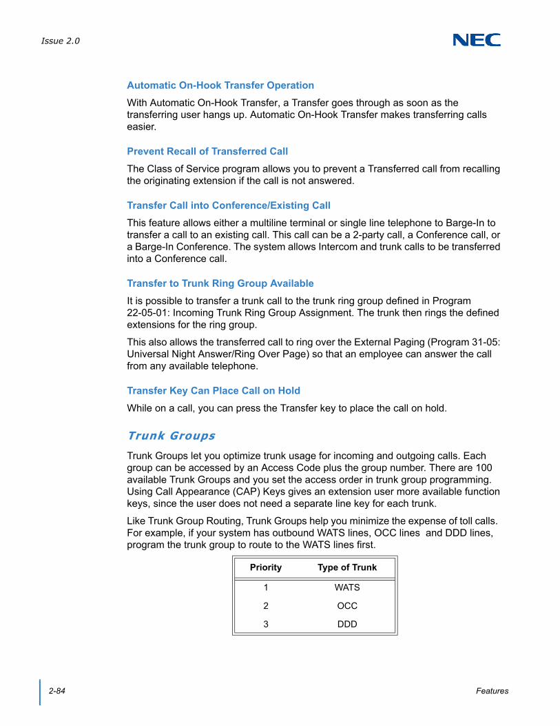
Issue 2.0
2-84 Features
Automatic On-Hook Transfer Operation
With Automatic On-Hook Transfer, a Transfer goes through as soon as the transferring user hangs up. Automatic On-Hook Transfer makes transferring calls easier.
Prevent Recall of Transferred Call
The Class of Service program allows you to prevent a Transferred call from recalling the originating extension if the call is not answered.
Transfer Call into Conference/Existing Call
This feature allows either a multiline terminal or single line telephone to Barge-In to transfer a call to an existing call. This call can be a 2-party call, a Conference call, or a Barge-In Conference. The system allows Intercom and trunk calls to be transferred into a Conference call.
Transfer to Trunk Ring Group Available
It is possible to transfer a trunk call to the trunk ring group defined in Program 22-05-01: Incoming Trunk Ring Group Assignment. The trunk then rings the defined extensions for the ring group.
This also allows the transferred call to ring over the External Paging (Program 31-05: Universal Night Answer/Ring Over Page) so that an employee can answer the call from any available telephone.
Transfer Key Can Place Call on Hold
While on a call, you can press the Transfer key to place the call on hold.
Trunk Groups
Trunk Groups let you optimize trunk usage for incoming and outgoing calls. Each group can be accessed by an Access Code plus the group number. There are 100 available Trunk Groups and you set the access order in trunk group programming. Using Call Appearance (CAP) Keys gives an extension user more available function keys, since the user does not need a separate line key for each trunk.
Like Trunk Group Routing, Trunk Groups help you minimize the expense of toll calls. For example, if your system has outbound WATS lines, OCC lines and DDD lines, program the trunk group to route to the WATS lines first.
Priority Type of Trunk
1 WATS
2 OCC
3 DDD
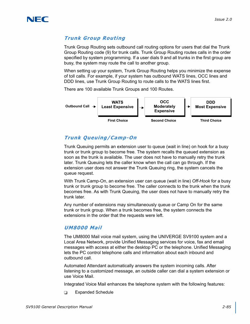
Issue 2.0
SV9100 General Description Manual 2-85
Trunk Group Routing
Trunk Group Routing sets outbound call routing options for users that dial the Trunk Group Routing code (9) for trunk calls. Trunk Group Routing routes calls in the order specified by system programming. If a user dials 9 and all trunks in the first group are busy, the system may route the call to another group.
When setting up your system, Trunk Group Routing helps you minimize the expense of toll calls. For example, if your system has outbound WATS lines, OCC lines and DDD lines, use Trunk Group Routing to route calls to the WATS lines first.
There are 100 available Trunk Groups and 100 Routes.
Trunk Queuing/Camp-On
Trunk Queuing permits an extension user to queue (wait in line) on hook for a busy trunk or trunk group to become free. The system recalls the queued extension as soon as the trunk is available. The user does not have to manually retry the trunk later. Trunk Queuing lets the caller know when the call can go through. If the extension user does not answer the Trunk Queuing ring, the system cancels the queue request.
With Trunk Camp-On, an extension user can queue (wait in line) Off-Hook for a busy trunk or trunk group to become free. The caller connects to the trunk when the trunk becomes free. As with Trunk Queuing, the user does not have to manually retry the trunk later.
Any number of extensions may simultaneously queue or Camp On for the same trunk or trunk group. When a trunk becomes free, the system connects the extensions in the order that the requests were left.
UM8000 Mail
The UM8000 Mail voice mail system, using the UNIVERGE SV9100 system and a Local Area Network, provide Unified Messaging services for voice, fax and email messages with access at either the desktop PC or the telephone. Unified Messaging lets the PC control telephone calls and information about each inbound and outbound call.
Automated Attendant automatically answers the system incoming calls. After listening to a customized message, an outside caller can dial a system extension or use Voice Mail.
Integrated Voice Mail enhances the telephone system with the following features:
Expanded Schedule
OCC Moderately Expensive
WATSLeast Expensive
DDDMost ExpensiveOutbound Call
First Choice Second Choice Third Choice
Issue 2.0
2-86 Features
Call Forwarding to Voice Mail
Leaving a Message
Transferring to Voice Mail
Live Record
Live Monitor
Voice Mail Overflow
Voice Mail Caller ID
Quick Transfer to Voice Mail
Optional UM8000 Mail TeLANophy Module Features
Text-to-Speech Using Nuance® RealSpeak™
ViewMail® with Live Record Module
ViewFax®
ViewCall® Plus
Hospitality Package
Additional Hospitality Languages
Networking
Multilingual Support
Supported Languages:
EMail Integration
uMobility – Wi-Fi Client
The uMobility Wi-Fi Client functions as a Standard SIP station on Blackberry®, iPhone and Android™ smart phones. The uMobility Wi-Fi Client allows the user to:
Answer incoming calls to the office telephone system directly from your smart phone.
ar = Argentinean ja = Japanese (hospitality only)
au = Australian English la = Latin America Spanish
ca = Catalan Spanish md = Mandarin Chinese
ct = Cantonese Chinese nl = Dutch
de = German nz = New Zealand English
dk = Danish pi = Iberian Portuguese
ed = Madrid Spanish pt = Portuguese
es = Mexican Spanish se = Swedish
fc = Canadian French uk = UK English
fr = Parisian French us = US English
he = Hebrew ru = Russian
it = Italian
Issue 2.0
SV9100 General Description Manual 2-87
Make calls from the smart phone that uses your office telephone system’s default number.
Hold and Transfer calls to other stations in the telephone system.
Talk on the smart phone and not use any cellular network minutes when using the uMobility Wi-Fi Client in a Wi-Fi hotspot at the office, at home or at a public hotspot.
Access work voice mail directly from your smart phone.
Enhancements
Answer calls during lock mode on iPhone.
G.729 is now supported.
iOS8 is now supported.
Unicast/Multicast Paging Mode
With SV9100 software the IP terminals (DT700/DT800 series) can receive an Internal Page via a Unicast or Multicast packet based upon system programming. This feature allows IP terminals (DT700/DT800 series) to be assigned to Unicast Mode, Multicast Mode, or Auto.
When the phone is set to Unicast Mode the internal paging is sent to the phone via a Unicast Packet.
When the phone is set to Multicast Mode the internal page is sent to the phone via a Multicast Packet.
When the phone is set to Auto, the internal page is sent to the phone either by Multicast or Unicast based on the subnet of the IP station. If the DT700/DT800 series terminal is in the same subnet as the GPZ-IPLE then it will receive the Internal Page via a Multicast Packet. If the DT700/DT800 series terminal is in a different subnet than the GPZ-IPLE the DT700/DT800 series will receive the Internal Page via a Unicast Packet.
When phones are set to receive Unicast packets the GPZ-IPLE will send a separate RTP stream to each phone that is set to receive the page. E.g. If there are five DT700/DT800 series IP phones in the page group and they are all set to Unicast Page Mode the GPZ-IPLE will send five separate RTP streams utilizing five DSP resources.
When the phones are set to receive Multicast packets the GPZ-IPLE will send one RTP stream. Multicast is a protocol that allows one device to communicate to multiple devices without the need to stream to the individual end point. E.g. If there are five DT700/DT800 series IP phones in the page group that are set to Multicast Mode, the GPZ-IPLE will send one RTP stream utilizing only one DSP resource.
Issue 2.0
2-88 Features
Uniform Call Distribution (UCD)
With Uniform Call Distribution (UCD), an extension user can call an idle extension in a programmed UCD Group (Department Group – 64 Department Groups available) by dialing the group pilot number. For example, this would let a caller dial the Sales department just by knowing the Sales department pilot number. The caller would not have to know any Sales department extension numbers.
User Log Out/Log In
An extension user can log out and log in to a UCD (Department) group. By logging out, the user removes their extension from the group. Once logged out, UCD (Department Calling) bypasses their extension. When they log back in, UCD (Department Calling) routes to their extension normally. All users can dial a code to log in or log out of their UCD (Department Calling) Group. A multiline terminal can optionally have a function key programmed for one-button log in and log out.
Enhanced Hunting
UCD (Department Calling) is enhanced with expanded hunting abilities. Hunting defines how calls to a UCD (Department Group) pilot number cycle through the members of the group. The hunting choices are:
Busy
Not Answered
Busy or Not Answered
If all members of the UCD (Department) group are busy, an incoming or transferred call to the group pilot number queues for an available member. Each group has a queue that can hold any number of waiting calls. If a display telephone is waiting in queue, the user sees: WAITING (group name). If a transferred call in queue is an outside call, and the system has a DSP daughter board installed with the VRS compact flash, the queued caller hears, “Please hold on. All lines are busy. Your call will be answered when a line becomes free.”
The VRS can also transfer calls to UCD (Department) groups. Refer to the Voice Response System (VRS) on page 2-93 feature for more information on setting up the VRS.
The system prevents hunting to a UCD (Department) group extension if it is:
Busy on a call
In Do Not Disturb
Call Forwarded
Logged Out
Issue 2.0
SV9100 General Description Manual 2-89
Uniform Numbering Network
Uniform Numbering Network allows multiple or compatible systems to be connected in a network using Tie Lines. A station user can dial a system number and a station number (open numbering) or dial the station number only (closed numbering) to access any station. When the calling and called systems are not directly connected, several Tie Lines may be accessed to route the call. Each system extends the call to the next system until the final destination is reached. Networking provides a seamless connection of multiple systems into a single “virtual” communications system using Tie Lines with a unified numbering plan.
Networking allows many companies to connect their telephone systems so they appear as one. An extension user in the network can easily dial another extension or transfer a call in the Networking System. Calls are passed from network node to network node using a protocol that contains information about the source of the call, the type of call and the destination of the call.
Flexible Network Routing
Use network routes to set up single-channel networking between many separate systems – or use multiple networking channels per system for greater network performance. Data tables in the system program define the routing for each extension in each network node. These tables are easily customized to meet the requirements of each networking configuration. Users may place an intercom call or transfer a call to any extension at any location by dialing an extension number. The system analyzes each extension number received and determines how to route the call to its final destination. The feature which handles this route selection is called Flexible Routing (F-Routing). F-Routing also can select alternate routes to the destination extension if the primary destination is busy. Up to 120 routes are available for networking. After an extension number is dialed, the system checks the routing, accesses the assigned trunk group and places the call. Each extension is assigned a route or routes that decide which trunk group to access and any modified dialed data if required.
Universal Slots
The UNIVERGE SV9100 has six universal slots, and up to four cabinets can be installed. The system uses the same chassis for the 64, 256 and unlimited systems to support up to 24 Universal Slots.
Up to four combined CHS2UG B-US/CHS2UG E (3-Slot Base/3-Slot Expansion) or CHS2UG-US (6-Slot) chassis can be connected locally to reach the system’s maximum port capacity.
EXAMPLE:
0 CHS2UG-US (19” Chassis) & 4 CHS2UG B-US/CHS2UG E (9.5” Base Chassis/9.5” Expansion Chassis)
1 CHS2UG-US (19” Chassis) & 3 CHS2UG B-US/CHS2UG E (9.5” Base Chassis/9.5” Expansion Chassis)
Issue 2.0
2-90 Features
2 CHS2UG-US (19” Chassis) & 2 CHS2UG B-US/CHS2UG E (9.5” Base Chassis/9.5” Expansion Chassis)
3 CHS2UG-US (19” Chassis) & 1 CHS2UG B-US/CHS2UG E (9.5” Base Chassis/9.5” Expansion Chassis)
4 CHS2UG-US (19” Chassis) & 0 CHS2UG B-US/CHS2UG E (9.5” Base Chassis/9.5” Expansion Chassis)
User Programming Ability
A station user can perform programming functions. Speed Group Dialing and Function Keys are just two features programmable from a station.
Virtual Extensions
Virtual Extensions are available software extensions on the Basic and Expanded Port Packages. A Virtual Extension assigned to a line key, can appear and ring on an individual station or multiple stations and be used for outbound access.
Virtual Extensions (VE) are shared with Call Arrival (CAR) Keys. In virtual extension mode, the key acts as a secondary extension. Up to 512 CAR/VE keys are provided.
Voice Call Recording
When using NEC DT 300 and DT 700 desktop terminals, telephone calls can be monitored, recorded and stored. For DT 300 (TDM) terminals, the NEC 4-Port Digital Call Logging Unit – VSR (Voice Security Recorder) is used. For DT 700 (IP) terminals, the NEC SonicView IP Recorder is used.
Dterm ® Voice Security Recorder (VSR)
The Dterm Voice Security Recorder is a USB device that taps across the digital extension pair of the NEC telephone system allowing digital recording of the telephone user’s conversation. The file created is saved Dterm either to the local PC or to a network location, depending on the application blade used. This adapter is for use with digital multiline terminals. It cannot be used to record VoIP phone conversations in a Netlink or CCIS configuration.
Two options are available for playing back calls recorded by your VSR(s). The first is the Desktop Player which is used by an individual user to play back their own archive of calls or to play back NEC Dterm VSR calls stored on their PC or network. It easily manages calls from one storage location. It does not offer many of the advanced functions of the VSR Manager, such as establishing preset shortcuts to any number of storage folders for quick and easy access.
Issue 2.0
SV9100 General Description Manual 2-91
The second player option is the VSR Manager. Take your call recording environment to the next level with NEC VSR application software. VSR Manager provides advanced visibility, access, retrieval, and playback tools for the VSR Recorder administrators. It provides an intuitive interface for establishing shortcuts to any number of storage folders and allows the supervisor to search across all storage folders for specific call information such as User, Time/Date, Length of Call, etc. The application can be used to access and manage VSR recordings whether created by the single port VSR or the 4-Port Digital Call Logging Unit. VSR Manager is built on the robust Microsoft.net frame-work and manipulates large volumes of recordings. It is a workhorse that delivers truly feature rich productivity tools in a familiar, ergonomic and easy to use MS Office style interface.
These two players can be combined in any number of configurations in the company, providing control and management where needed and simple playback in other locations.
NEC SonicView™ IP Recorder (1.0)
The NEC SonicView™ IP Recorder application is an easy-to-use yet powerful web-based call recording solution. The SonicView software offers robust features designed specifically for business users who want to make use of Enterprise call data for reporting, analysis and monitoring. The different components that make up the SonicView application are:
Application Server
Database Server
Recording Engine
Network Infrastructure to Enable Call Recording
NEC SonicView Recorder (TDM and IP) (2.0)
The NEC SonicView™ Recorder application is an easy-to-use yet powerful web-based call recording solution use for both IP and TDM calls. The SonicView software offers robust features designed specifically for business users who want to make use of Enterprise call data for reporting, analysis and monitoring. The different components that make up the SonicView application are:
Application Server
Database Server
Recording Engine
Network Infrastructure to Enable Call Recording
Issue 2.0
2-92 Features
NEC SonicView Recorder (2.7)
The NEC SonicView™ Recorder application is an easy-to-use yet powerful web-based call recording solution. The SonicView software offers robust features designed specifically for business users who want to make use of Enterprise call data for reporting, analysis and monitoring.
Voice Mail Integration (Analog)
The system provides telephone users with comprehensive Voice Mail features. Voice Mail ends the frustration and cost of missed calls, inaccurate written messages and telephone tag. This frees busy company receptionists and secretaries for more productive work.
External voice mail requires available analog station ports based on the number of voice mail ports connected.
Integrated voice mail enhances the telephone system with the following features:
Call Forwarding to Voice Mail
Leaving a Message
Transferring to Voice Mail
Voice Mail Queuing
When accessing the voice mail, the system provides a voice mail queue. If all the voice mail ports are busy, any call trying to get to the voice mail is placed in queue. As the voice mail ports become available, the calls are connected to the voice mail in the order in which they were received.
As the Voice Mail Queue follows Department Hunting programming, the queue can hold a maximum of 10 calls. If the queue is full or if the voice mail ports are not assigned to a Department Group, the calls are handled as though no voice mail queuing feature is enabled. The calls either access voice mail if a port is available or they receive a busy signal.
The Voice Mail Queuing feature does not work with the Conversation Record feature.
MSG Key will Operate as Voice Mail Key
The system enhances a telephone MSG key function when connected to a system which has Voice Mail installed. When an extension receives a Voice Mail, the MSG key can be used to check the number of messages in Voice Mail or call the Voice Mail to listen to the messages.
Voice Mail Message Indication on Line Keys
Voice Mail Message Indication on Line Keys indicates a new Voice Mail message on Line Keys or DSS/BLF keys.
Issue 2.0
SV9100 General Description Manual 2-93
Voice Over
Voice Over lets a user interrupt a busy station user that is on another call. With Voice Over, the busy extension user hears an alert tone followed by the voice of the interrupting party. The extension user receiving the Voice Over can respond to the interrupting party without being heard by the original caller. If desired, the user can easily switch between their original caller and the interrupting co-worker. The original caller and the interrupting party can never hear each other.
Voice Over could help a lawyer, for example, waiting for an urgent call. While on a call with another client, the lawyer paralegal could announce the urgent call as soon as it comes in. The lawyer could then give the paralegal instructions how to handle the situation – all without the original client hearing the conversation.
Both multiline terminal users and 500/2500 set users can initiate and receive a Voice Over.
To enable Voice Over, a multiline terminal can have a function key programmed for Voice Over. In addition to one-touch Voice Over operation, the key shows the Voice Over status as follows:
Voice Response System (VRS)
With appropriate licensing the SV9100 provides the option for the Voice Response System (VRS) which gives the system voice recording and playback ability. The VRS CompactFlash card provides up to 100 system messages (General Message, Automated Attendant greetings, messages and the 900 Preamble).
General Message – provides a recorded message which any user can hear.
Automated Attendant (Operator Assistance) – answers incoming calls, plays a greeting to the caller, and then lets the caller directly dial a system extension.
Messages – provides announcement and overflow messages for groups.
Transfer to the VRS – allows any extension user to Transfer their outside call to the VRS.
Voice Prompting Messages – plays call and feature status messages to users.
900 Preamble – alerts callers using 900 lines of the cost and features of the pay-per-call service.
Time, Date and Station Number Check – lets a multiline terminal extension user quickly hear a recording for the time, date, or the extension number.
When the key is . . . You are . . .
Off Not using Voice Over
Flashing (Red) Listening to the interrupting party
On (Green) Responding to the interrupting party
Issue 2.0
2-94 Features
Voice Response System (VRS) Upload Download Audio
The Voice Response System (VRS) Upload Download Audio feature allows the upload of VRS greetings up to 1MB in size, recorded on a PC or professionally, to any valid VRS message in the system. It also allows users to listen to and delete VRS messages from callers. Access to the InMail/VRS compact flash drive is via the HTML User Pro (Web Pro).
The User Admin (UA Mode) can change Routing Mailbox greetings for the following Routing mailbox types: Instruction (Call Routing), Announcement and Group.
Voice Response System (VRS) – Call Forwarding – Park and Page
When an extension user is away from their phone, VRS Park and Page can let them know when they have a call waiting to be answered. The Personal Greeting and Park & Page options can have up to 200 messages total (note that the Park & Page feature uses two messages). To enable VRS Park and Page, the user records a Personal Greeting along with an additional Paging announcement. VRS Park and Page then answers an incoming call and plays the Personal Greeting to the caller. The caller then listens to Music on Hold (if available) while the system broadcasts the recorded Paging announcement. When the extension user hears the Page, they can go to any telephone and use Directed Call Pickup to intercept the call.
Volume Controls
Each multiline terminal user can control the volume of incoming ringing, splash tone, Paging, Background Music, Handsfree and your handset. Multiline terminals consolidate all adjustments into the volume buttons. Press the VOLUME or VOLUME to adjust the volume level for the active feature (e.g., outside call, ICM, ICM ringing, or paging). Press these keys when the telephone is idle to adjust the contrast level of the telephone display. The users should set the volumes for their most comfortable level.
Warning Tone for Long Conversation
The system can broadcast warning tones to a trunk caller warning the user that he has been on the call too long. If he chooses, the caller can disregard the tones and continue talking. The outside caller does not hear the warning tones. Warning tones do not occur for Intercom calls and most incoming trunk calls. DISA trunks can also have warning tones. Warning tones are not available to analog single line telephone (SLT) users.
There are two warning tones: Alarm Tone 1 and Alarm Tone 2. Alarm Tone 1 is the first set of tones that occur after the user initially places a trunk call. Alarm Tone 2 broadcasts periodically after Alarm Tone 1 as a continued reminder. Each alarm tone consists of three short beeps.
If programmed, DISA is disconnected unless the continue code is entered by the user. With the Long Conversation Cutoff feature, incoming or outgoing central office calls can also be disconnected.
Issue 2.0
SV9100 General Description Manual 2-95
Warning Tone for DISA Callers
For DISA callers, with this feature enabled, the warning tone time begins when an incoming DISA call places an outgoing call and either the inter-digit time expires or the outgoing call is answered.
If an outside call is transferred to forwarded off-premise using an outside trunk, the warning tone timer begins immediately. This occurs only if either trunk involved in the call is programmed for this feature (Program 14-01-17). To transfer a trunk call off-premise, Program 14-01-13 must be set to 1.
Wireless DECT (SIP)
The Wireless DECT (SIP) (Digital Enhanced Cordless Telecommunication) system allows using DECT 6.0 DECT (SIP) handsets. These handsets provide the freedom and convenience of a wireless telephone but also allow access to features provided by the UNIVERGE SV9100 system.
The number of Wireless DECT (SIP) handsets supported by the UNIVERGE SV9100 is dependent on the number of SIP Client licenses.
Off-Hook Signaling
This feature enables the display of off-hook signaling on an IP DECT terminal while talking with the 1st call.
Caller ID Display After a Call Transfer
Previously in case of screened transfer, if a call was from a trunk line or legacy terminal, etc, the transferrer's calling party number was displayed in IP DECT. In case of an unscreened transfer, the calling party number from where the call was transferred is displayed on the IP DECT.
This feature enables the IP DECT terminal to display the calling party number of the original caller (Transferee) when making a screened or unscreened transfer to an IP DECT terminal.
Out of Range Call Warning Notification
With SV9100 software, it is possible to determine when a SIP-Dect terminal is Out of Range or powered off. When an internal caller calls the Out of Range SIP terminal, either a lock out tone or call forwarding can be performed

Issue 2.0
2-96 Features
SV9100 General Description Manual 3-1
Chapter 3
UNIVERGE® SV9100
Equipment
SECTION 1 EQUIPMENT LIST
The following tables list all equipment for the SV9100 system.
Table 3-1 Chassis Equipment List
Equipment Name Equipment Description
CHS2UG-US 19” Chassis (6-slot)
CHS2UG GW-US 9.5” Gateway Chassis (3-slot)
CHS2UG B-US 9.5” Base Chassis (3-slot)
CHS2UG E 9.5” Expansion Chassis (3-slot)
Table 3-2 Chassis Installation Equipment List
Equipment Name Equipment Description
CHS2UG MOVABLE WALL MOUNT KIT
Movable Wall Mount Set for CHS2UG B-US and CHS2UG E chassis
CHS BASE UNIT Floor Mount Set for all chassis (CHS1UG-US and CHS2UG-US)
CHS2UG BLANK SLOT COVER KIT
Blank Slot Cover Set
CHS2UG JOINT BRACKET KIT Upper Joint Bracket for 6-slot Chassis
CHS2UG RACK MOUNT KIT Rack Mount for CHS2UG-US Chassis
CHS1UG/2UG WALL MOUNT KIT Wall Mount Set for CHS2UG-US Chassis
CHS2UG Stand Kit (K) Stand Mount Kit for 2UG Chassis
CHS2UG STAND KIT (EXT) Expansion Plate for Stand Mount Kit for 6-blade Chassis, 2 sets
CHS1UG BLANK SLOT COVER KIT(BUS)
Blank Bus Cover
IP5D-RACK MOUNT BAR SET Rack Mount Set for CHS2UG B-US and CHS2UG E
Issue 2.0
3-2 Equipment
Table 3-3 Battery Mount Equipment List
Equipment Name Equipment Description
CHS2UG B SMALL BATT BOX Short-term battery box for 3-slot chassisBackup Time – 10 minutes
CHSG LARGE BATT BOX Long Term battery box for CHS1UG-US and CHS2UG-US ChassisCable between batteries – 9.06in/230mmFuse Unit to Batteries – 18.11ln/460mmCable from chassis to battery box – 81.1in/2060mm
CHS2UG BATT MTG KIT Battery Mount for CHS2UG-US ChassisBackup time – 10 minutes
CHSGW SMALL BATT SET Short-term battery set for 3-slot chassis
CHS LARGE BATT SET Long term battery set(3) 12V 7Ah SLA Batteries with Faston 187 terminals
CHS2UG INT BATT SET Internal battery set for CHS2UG-US chassis12V 2.3Ah SLA Battery with Faston 187
Table 3-4 Blade Equipment List
Equipment Name Abbreviations Equipment Description
PZ-BS10 BUS0 Expansion Chassis Interface Unit, 3-jack
GPZ-BS11 BUS1 Expansion Chassis Interface Unit, 1-jack
GCD-8DLCA DLC 8-port Digital Station Interface
GPZ-8DLCB DLCDB 8-port Digital Station Interface on GCD-8DLCA
GCD-16DLCA DLC 16-port Digital Station Interface
GCD-4COTB COT 4-port Loop/ground Start Trunks
GPZ-4COTF COTDB 4-port Loop/ground Start Trunks on GCD-4COTB, GCD-LTA
GCD-4LCA LC 4-port Single Line Telephone Interface
GPZ-4LCA LCDB 4-port Single Line Telephone Interface on GCD-4LCA and GCD-8LCA
GCD-8LCA LC 8-port Single Line Telephone Interface
GPZ-8LCE LCDB 8-port Single Line Telephone Interface on GCD-4LCA and GCD-8LCA
GCD-2BRIA BRT 2 Basic Rate Interface
GPZ-2BRIA BRTDB 2 Basic Rate Interface on GCD-2BRIA, for SV9100 can also be mounted on the GCD-LTA blade
GCD-PRTA PRT 1 Primary Rate Interface
GCD-CCTA CCT Common Channel Interoffice Signaling Trunk Interface/Common Channel Handler
Issue 2.0
SV9100 General Description Manual 3-3
GCD-4DIOPA DIOP 4 DID/OPX
GCD-4ODTA ODT 4-port Tie Line Interface (E&M)
GCD-LTA LTA 8 Digital Station/2SLT for GCD-CP10 only
GPZ-IPLE VoIPDB VOIP on the CPU
GCD-VM00 VM00 Voice Mail and Server
GCD-ETIA GSWU PoE Gigabit Switch Unit
GCD-PVAA PMS Packet Voice Application
GCD-SVR2 SVR2 Server blade
GCD-CP10 CPU Main Processor Blade for KTS
SD-A1 US 1G-APP-CF 1GB InMail SD Card
SD-B1 US 4G-APP-CF 4GB InMail SD Card
GCD-RGA RGA Application Gateway – Router and Conference
GCD-4LCF LC 4-port Single Line Telephone Interface
GCD-8LCF LC 8-port Single Line Telephone Interface
GPZ-4LCF LCDB 4-port Single Line Telephone Interface on GCD-4LCF and GCD-8LCF
GPZ-8LCF LCDB 8-port Single Line Telephone Interface on GCD-4LCF and GCD-8LCF
AKS-RGA-APP-GATEWAY-CF
AKS-RGA CF Application Gateway – Compact Flash
Table 3-5 Cable Equipment List
Equipment Name Equipment Description
RS CONSOLE CA-A MAT (PCPro) Cable 6.6 ft. (2.0m)
RS NORM-4S CA-F RS-232C Cable (normal) 13.1 ft (4m)
RS RVS-15S CA-F RS-232C Cable (reverse) 49.2 ft (15.0m)
RS RVS-4S CA-F RS 232C Cable (reverse) 13.1 ft (4.0m)
RS RVS-4S CA-G RS 232C Cable (reverse) 13.1 ft (4.0m)
RS PRT-15S CA-F RS-232C Cable (printer) 49.2 ft (15.0m)
BUS CABLE Bus Cable
AC CORD AC Power Cable for US
Table 3-4 Blade Equipment List (Continued)
Equipment Name Abbreviations Equipment Description
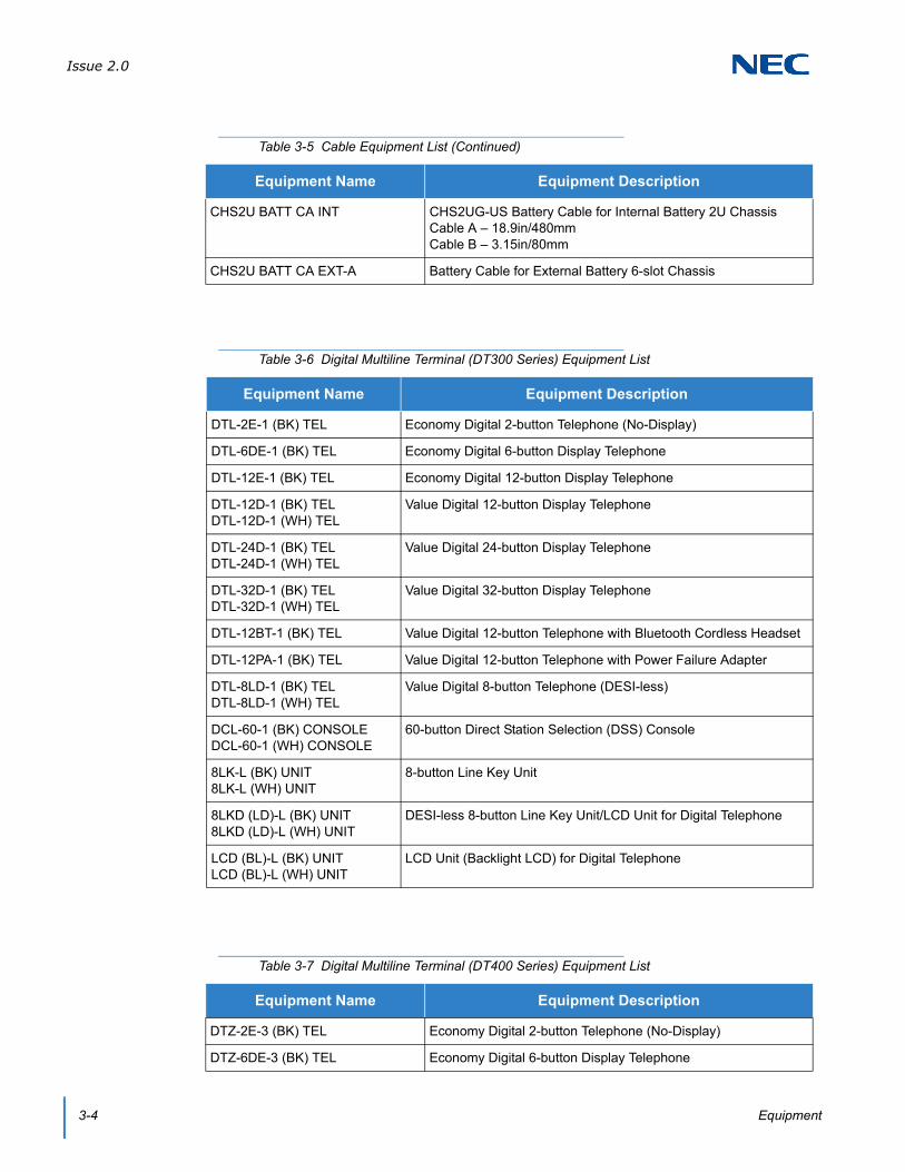
Issue 2.0
3-4 Equipment
CHS2U BATT CA INT CHS2UG-US Battery Cable for Internal Battery 2U ChassisCable A – 18.9in/480mmCable B – 3.15in/80mm
CHS2U BATT CA EXT-A Battery Cable for External Battery 6-slot Chassis
Table 3-6 Digital Multiline Terminal (DT300 Series) Equipment List
Equipment Name Equipment Description
DTL-2E-1 (BK) TEL Economy Digital 2-button Telephone (No-Display)
DTL-6DE-1 (BK) TEL Economy Digital 6-button Display Telephone
DTL-12E-1 (BK) TEL Economy Digital 12-button Display Telephone
DTL-12D-1 (BK) TELDTL-12D-1 (WH) TEL
Value Digital 12-button Display Telephone
DTL-24D-1 (BK) TELDTL-24D-1 (WH) TEL
Value Digital 24-button Display Telephone
DTL-32D-1 (BK) TELDTL-32D-1 (WH) TEL
Value Digital 32-button Display Telephone
DTL-12BT-1 (BK) TEL Value Digital 12-button Telephone with Bluetooth Cordless Headset
DTL-12PA-1 (BK) TEL Value Digital 12-button Telephone with Power Failure Adapter
DTL-8LD-1 (BK) TELDTL-8LD-1 (WH) TEL
Value Digital 8-button Telephone (DESI-less)
DCL-60-1 (BK) CONSOLEDCL-60-1 (WH) CONSOLE
60-button Direct Station Selection (DSS) Console
8LK-L (BK) UNIT8LK-L (WH) UNIT
8-button Line Key Unit
8LKD (LD)-L (BK) UNIT8LKD (LD)-L (WH) UNIT
DESI-less 8-button Line Key Unit/LCD Unit for Digital Telephone
LCD (BL)-L (BK) UNITLCD (BL)-L (WH) UNIT
LCD Unit (Backlight LCD) for Digital Telephone
Table 3-7 Digital Multiline Terminal (DT400 Series) Equipment List
Equipment Name Equipment Description
DTZ-2E-3 (BK) TEL Economy Digital 2-button Telephone (No-Display)
DTZ-6DE-3 (BK) TEL Economy Digital 6-button Display Telephone
Table 3-5 Cable Equipment List (Continued)
Equipment Name Equipment Description
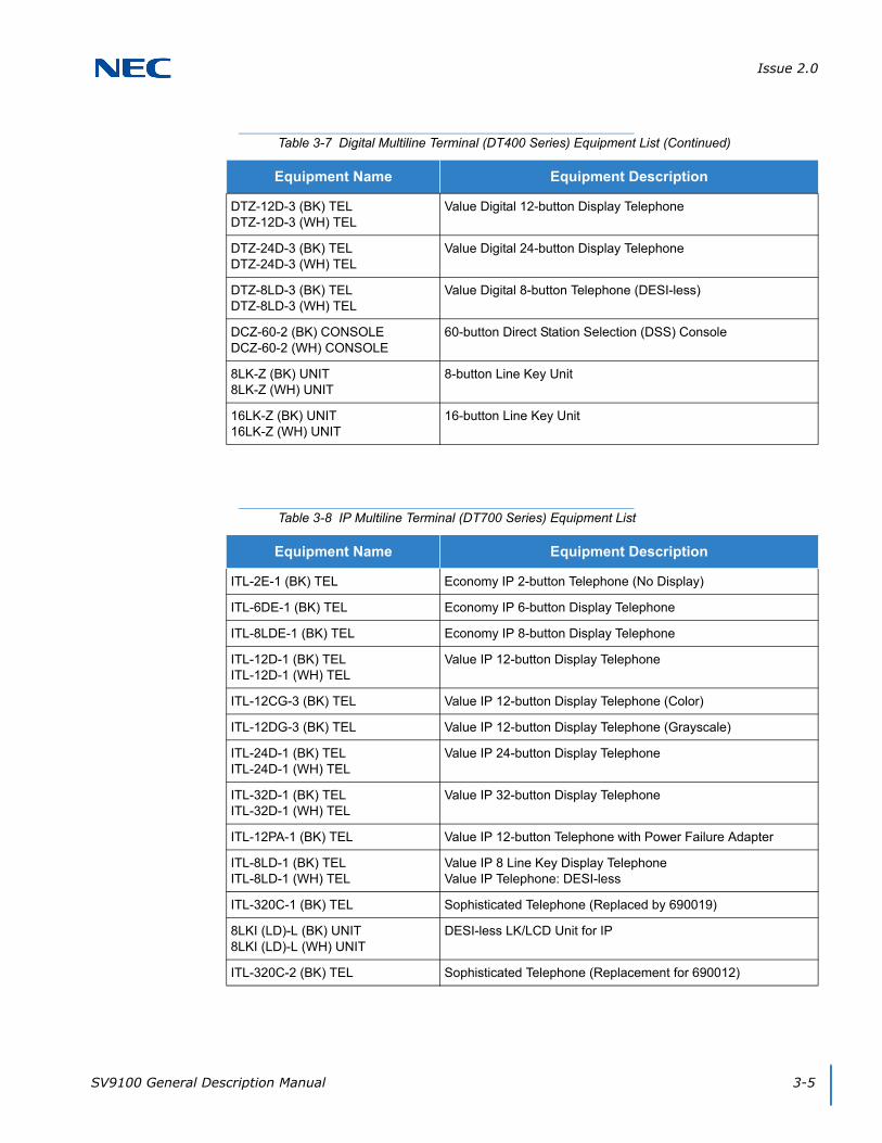
Issue 2.0
SV9100 General Description Manual 3-5
DTZ-12D-3 (BK) TELDTZ-12D-3 (WH) TEL
Value Digital 12-button Display Telephone
DTZ-24D-3 (BK) TELDTZ-24D-3 (WH) TEL
Value Digital 24-button Display Telephone
DTZ-8LD-3 (BK) TELDTZ-8LD-3 (WH) TEL
Value Digital 8-button Telephone (DESI-less)
DCZ-60-2 (BK) CONSOLEDCZ-60-2 (WH) CONSOLE
60-button Direct Station Selection (DSS) Console
8LK-Z (BK) UNIT8LK-Z (WH) UNIT
8-button Line Key Unit
16LK-Z (BK) UNIT16LK-Z (WH) UNIT
16-button Line Key Unit
Table 3-8 IP Multiline Terminal (DT700 Series) Equipment List
Equipment Name Equipment Description
ITL-2E-1 (BK) TEL Economy IP 2-button Telephone (No Display)
ITL-6DE-1 (BK) TEL Economy IP 6-button Display Telephone
ITL-8LDE-1 (BK) TEL Economy IP 8-button Display Telephone
ITL-12D-1 (BK) TELITL-12D-1 (WH) TEL
Value IP 12-button Display Telephone
ITL-12CG-3 (BK) TEL Value IP 12-button Display Telephone (Color)
ITL-12DG-3 (BK) TEL Value IP 12-button Display Telephone (Grayscale)
ITL-24D-1 (BK) TELITL-24D-1 (WH) TEL
Value IP 24-button Display Telephone
ITL-32D-1 (BK) TELITL-32D-1 (WH) TEL
Value IP 32-button Display Telephone
ITL-12PA-1 (BK) TEL Value IP 12-button Telephone with Power Failure Adapter
ITL-8LD-1 (BK) TELITL-8LD-1 (WH) TEL
Value IP 8 Line Key Display TelephoneValue IP Telephone: DESI-less
ITL-320C-1 (BK) TEL Sophisticated Telephone (Replaced by 690019)
8LKI (LD)-L (BK) UNIT8LKI (LD)-L (WH) UNIT
DESI-less LK/LCD Unit for IP
ITL-320C-2 (BK) TEL Sophisticated Telephone (Replacement for 690012)
Table 3-7 Digital Multiline Terminal (DT400 Series) Equipment List (Continued)
Equipment Name Equipment Description
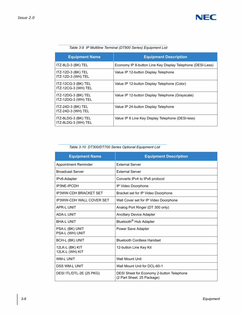
Issue 2.0
3-6 Equipment
Table 3-9 IP Multiline Terminal (DT800 Series) Equipment List
Equipment Name Equipment Description
ITZ-8LD-3 (BK) TEL Economy IP 8-button Line Key Display Telephone (DESI-Less)
ITZ-12D-3 (BK) TELITZ-12D-3 (WH) TEL
Value IP 12-button Display Telephone
ITZ-12CG-3 (BK) TELITZ-12CG-3 (WH) TEL
Value IP 12-button Display Telephone (Color)
ITZ-12DG-3 (BK) TELITZ-12DG-3 (WH) TEL
Value IP 12-button Display Telephone (Grayscale)
ITZ-24D-3 (BK) TELITZ-24D-3 (WH) TEL
Value IP 24-button Display Telephone
ITZ-8LDG-3 (BK) TELITZ-8LDG-3 (WH) TEL
Value IP 8 Line Key Display Telephone (DESI-less)
Table 3-10 DT300/DT700 Series Optional Equipment List
Equipment Name Equipment Description
Appointment Reminder External Server
Broadcast Server External Server
IPv6-Adapter Converts IPv4 to IPv6 protocol
IP3NE-IPCDH IP Video Doorphone
IP3WW-CDH BRACKET SET Bracket set for IP Video Doorphone
IP3WW-CDH WALL COVER SET Wall Cover set for IP Video Doorphone
APR-L UNIT Analog Port Ringer (DT 300 only)
ADA-L UNIT Ancillary Device Adapter
BHA-L UNIT Bluetooth® Hub Adapter
PSA-L (BK) UNITPSA-L (WH) UNIT
Power Save Adapter
BCH-L (BK) UNIT Bluetooth Cordless Handset
12LK-L (BK) KIT12LK-L (WH) KIT
12-button Line Key Kit
WM-L UNIT Wall Mount Unit
DSS WM-L UNIT Wall Mount Unit for DCL-60-1
DESI ITL/DTL-2E (25 PKG) DESI Sheet for Economy 2-button Telephone(2 Part Sheet, 25 Package)
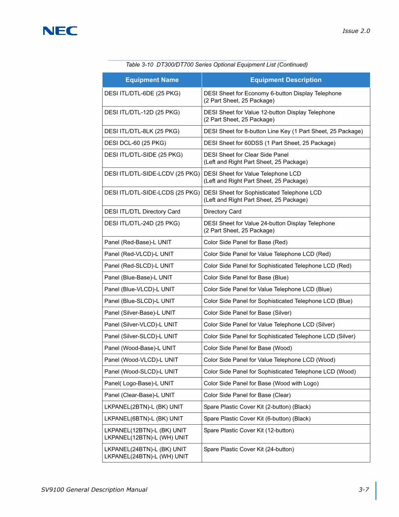
Issue 2.0
SV9100 General Description Manual 3-7
DESI ITL/DTL-6DE (25 PKG) DESI Sheet for Economy 6-button Display Telephone(2 Part Sheet, 25 Package)
DESI ITL/DTL-12D (25 PKG) DESI Sheet for Value 12-button Display Telephone(2 Part Sheet, 25 Package)
DESI ITL/DTL-8LK (25 PKG) DESI Sheet for 8-button Line Key (1 Part Sheet, 25 Package)
DESI DCL-60 (25 PKG) DESI Sheet for 60DSS (1 Part Sheet, 25 Package)
DESI ITL/DTL-SIDE (25 PKG) DESI Sheet for Clear Side Panel(Left and Right Part Sheet, 25 Package)
DESI ITL/DTL-SIDE-LCDV (25 PKG) DESI Sheet for Value Telephone LCD(Left and Right Part Sheet, 25 Package)
DESI ITL/DTL-SIDE-LCDS (25 PKG) DESI Sheet for Sophisticated Telephone LCD (Left and Right Part Sheet, 25 Package)
DESI ITL/DTL Directory Card Directory Card
DESI ITL/DTL-24D (25 PKG) DESI Sheet for Value 24-button Display Telephone(2 Part Sheet, 25 Package)
Panel (Red-Base)-L UNIT Color Side Panel for Base (Red)
Panel (Red-VLCD)-L UNIT Color Side Panel for Value Telephone LCD (Red)
Panel (Red-SLCD)-L UNIT Color Side Panel for Sophisticated Telephone LCD (Red)
Panel (Blue-Base)-L UNIT Color Side Panel for Base (Blue)
Panel (Blue-VLCD)-L UNIT Color Side Panel for Value Telephone LCD (Blue)
Panel (Blue-SLCD)-L UNIT Color Side Panel for Sophisticated Telephone LCD (Blue)
Panel (Silver-Base)-L UNIT Color Side Panel for Base (Silver)
Panel (Silver-VLCD)-L UNIT Color Side Panel for Value Telephone LCD (Silver)
Panel (Silver-SLCD)-L UNIT Color Side Panel for Sophisticated Telephone LCD (Silver)
Panel (Wood-Base)-L UNIT Color Side Panel for Base (Wood)
Panel (Wood-VLCD)-L UNIT Color Side Panel for Value Telephone LCD (Wood)
Panel (Wood-SLCD)-L UNIT Color Side Panel for Sophisticated Telephone LCD (Wood)
Panel( Logo-Base)-L UNIT Color Side Panel for Base (Wood with Logo)
Panel (Clear-Base)-L UNIT Color Side Panel for Base (Clear)
LKPANEL(2BTN)-L (BK) UNIT Spare Plastic Cover Kit (2-button) (Black)
LKPANEL(6BTN)-L (BK) UNIT Spare Plastic Cover Kit (6-button) (Black)
LKPANEL(12BTN)-L (BK) UNITLKPANEL(12BTN)-L (WH) UNIT
Spare Plastic Cover Kit (12-button)
LKPANEL(24BTN)-L (BK) UNITLKPANEL(24BTN)-L (WH) UNIT
Spare Plastic Cover Kit (24-button)
Table 3-10 DT300/DT700 Series Optional Equipment List (Continued)
Equipment Name Equipment Description
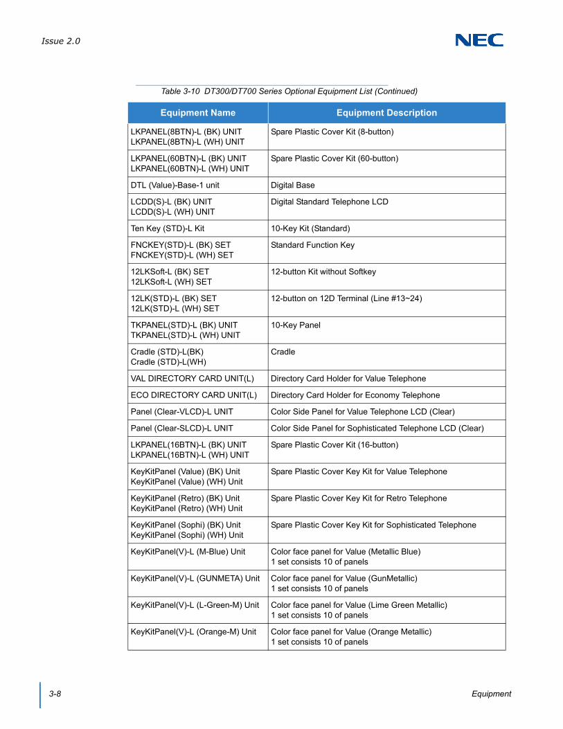
Issue 2.0
3-8 Equipment
LKPANEL(8BTN)-L (BK) UNITLKPANEL(8BTN)-L (WH) UNIT
Spare Plastic Cover Kit (8-button)
LKPANEL(60BTN)-L (BK) UNITLKPANEL(60BTN)-L (WH) UNIT
Spare Plastic Cover Kit (60-button)
DTL (Value)-Base-1 unit Digital Base
LCDD(S)-L (BK) UNITLCDD(S)-L (WH) UNIT
Digital Standard Telephone LCD
Ten Key (STD)-L Kit 10-Key Kit (Standard)
FNCKEY(STD)-L (BK) SETFNCKEY(STD)-L (WH) SET
Standard Function Key
12LKSoft-L (BK) SET12LKSoft-L (WH) SET
12-button Kit without Softkey
12LK(STD)-L (BK) SET12LK(STD)-L (WH) SET
12-button on 12D Terminal (Line #13~24)
TKPANEL(STD)-L (BK) UNITTKPANEL(STD)-L (WH) UNIT
10-Key Panel
Cradle (STD)-L(BK)Cradle (STD)-L(WH)
Cradle
VAL DIRECTORY CARD UNIT(L) Directory Card Holder for Value Telephone
ECO DIRECTORY CARD UNIT(L) Directory Card Holder for Economy Telephone
Panel (Clear-VLCD)-L UNIT Color Side Panel for Value Telephone LCD (Clear)
Panel (Clear-SLCD)-L UNIT Color Side Panel for Sophisticated Telephone LCD (Clear)
LKPANEL(16BTN)-L (BK) UNITLKPANEL(16BTN)-L (WH) UNIT
Spare Plastic Cover Kit (16-button)
KeyKitPanel (Value) (BK) UnitKeyKitPanel (Value) (WH) Unit
Spare Plastic Cover Key Kit for Value Telephone
KeyKitPanel (Retro) (BK) UnitKeyKitPanel (Retro) (WH) Unit
Spare Plastic Cover Key Kit for Retro Telephone
KeyKitPanel (Sophi) (BK) UnitKeyKitPanel (Sophi) (WH) Unit
Spare Plastic Cover Key Kit for Sophisticated Telephone
KeyKitPanel(V)-L (M-Blue) Unit Color face panel for Value (Metallic Blue)1 set consists 10 of panels
KeyKitPanel(V)-L (GUNMETA) Unit Color face panel for Value (GunMetallic)1 set consists 10 of panels
KeyKitPanel(V)-L (L-Green-M) Unit Color face panel for Value (Lime Green Metallic)1 set consists 10 of panels
KeyKitPanel(V)-L (Orange-M) Unit Color face panel for Value (Orange Metallic)1 set consists 10 of panels
Table 3-10 DT300/DT700 Series Optional Equipment List (Continued)
Equipment Name Equipment Description
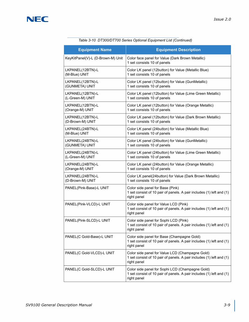
Issue 2.0
SV9100 General Description Manual 3-9
KeyKitPanel(V)-L (D-Brown-M) Unit Color face panel for Value (Dark Brown Metallic)1 set consists 10 of panels
LKPANEL(12BTN)-L(M-Blue) UNIT
Color LK panel (12button) for Value (Metallic Blue)1 set consists 10 of panels
LKPANEL(12BTN)-L(GUNMETA) UNIT
Color LK panel (12button) for Value (GunMetallic)1 set consists 10 of panels
LKPANEL(12BTN)-L(L-Green-M) UNIT
Color LK panel (12button) for Value (Lime Green Metallic)1 set consists 10 of panels
LKPANEL(12BTN)-L(Orange-M) UNIT
Color LK panel (12button) for Value (Orange Metallic)1 set consists 10 of panels
LKPANEL(12BTN)-L(D-Brown-M) UNIT
Color LK panel (12button) for Value (Dark Brown Metallic)1 set consists 10 of panels
LKPANEL(24BTN)-L(M-Blue) UNIT
Color LK panel (24button) for Value (Metallic Blue)1 set consists 10 of panels
LKPANEL(24BTN)-L(GUNMETA) UNIT
Color LK panel (24button) for Value (GunMetallic)1 set consists 10 of panels
LKPANEL(24BTN)-L(L-Green-M) UNIT
Color LK panel (24button) for Value (Lime Green Metallic)1 set consists 10 of panels
LKPANEL(24BTN)-L(Orange-M) UNIT
Color LK panel (24button) for Value (Orange Metallic)1 set consists 10 of panels
LKPANEL(24BTN)-L(D-Brown-M) UNIT
Color LK panel(24button) for Value (Dark Brown Metallic)1 set consists 10 of panels
PANEL(Pink-Base)-L UNIT Color side panel for Base (Pink)1 set consist of 10 pair of panels. A pair includes (1) left and (1) right panel
PANEL(Pink-VLCD)-L UNIT Color side panel for Value LCD (Pink)1 set consist of 10 pair of panels. A pair includes (1) left and (1) right panel
PANEL(Pink-SLCD)-L UNIT Color side panel for Sophi LCD (Pink)1 set consist of 10 pair of panels. A pair includes (1) left and (1) right panel
PANEL(C Gold-Base)-L UNIT Color side panel for Base (Champagne Gold)1 set consist of 10 pair of panels. A pair includes (1) left and (1) right panel
PANEL(C Gold-VLCD)-L UNIT Color side panel for Value LCD (Champagne Gold)1 set consist of 10 pair of panels. A pair includes (1) left and (1) right panel
PANEL(C Gold-SLCD)-L UNIT Color side panel for Sophi LCD (Champagne Gold)1 set consist of 10 pair of panels. A pair includes (1) left and (1) right panel
Table 3-10 DT300/DT700 Series Optional Equipment List (Continued)
Equipment Name Equipment Description
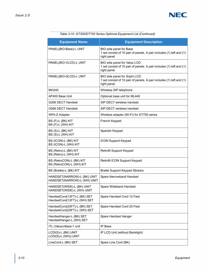
Issue 2.0
3-10 Equipment
PANEL(BIO-Base)-L UNIT BIO side panel for Base1 set consist of 10 pair of panels. A pair includes (1) left and (1) right panel
PANEL(BIO-VLCD)-L UNIT BIO side panel for Value LCD1 set consist of 10 pair of panels. A pair includes (1) left and (1) right panel
PANEL(BIO-SLCD)-L UNIT BIO side panel for Sophi LCD1 set consist of 10 pair of panels. A pair includes (1) left and (1) right panel
MH240 Wireless SIP telephone
AP400 Base Unit Optional base unit for ML440
G266 DECT Handset SIP DECT wireless handset
G566 DECT Handset SIP DECT wireless handset
WFA-Z Adapter Wireless adapter (Wi-Fi) for DT700 series
BS (F)-L (BK) KITBS (F)-L (WH) KIT
French Keypad
BS (S)-L (BK) KITBS (S)-L (WH) KIT
Spanish Keypad
BS (ICON)-L (BK) KITBS (ICON)-L (WH) KIT
ICON Support Keypad
BS (Retro)-L (BK) KITBS (Retro)-L (WH) KIT
Retrofit Support Keypad
BS (RetroCON)-L (BK) KITBS (RetroCON)-L (WH) KIT
Retrofit ICON Support Keypad
BS (Braille)-L (BK) KIT Braille Support Keypad Stickers
HANDSET(NARROW)-L (BK) UNITHANDSET(NARROW)-L (WH) UNIT
Spare Narrowband Handset
HANDSET(WIDE)-L (BK) UNITHANDSET(WIDE)-L (WH) UNIT
Spare Wideband Handset
HandsetCord(12FT)-L (BK) SETHandsetCord(12FT)-L (WH) SET
Spare Handset Cord 12 Feet
HandsetCord(25FT)-L (BK) SETHandsetCord(25FT)-L (WH) SET
Spare Handset Cord 25 Feet
HandsetHanger-L (BK) SETHandsetHanger-L (WH) SET
Spare Handset Hanger
ITL (Value)-Base-1 unit IP Base
LCDI(S)-L (BK) UNITLCDI(S)-L (WH)) UNIT
IP LCD Unit (without Backlight)
LineCord-L (BK) SET Spare Line Cord (BK)
Table 3-10 DT300/DT700 Series Optional Equipment List (Continued)
Equipment Name Equipment Description
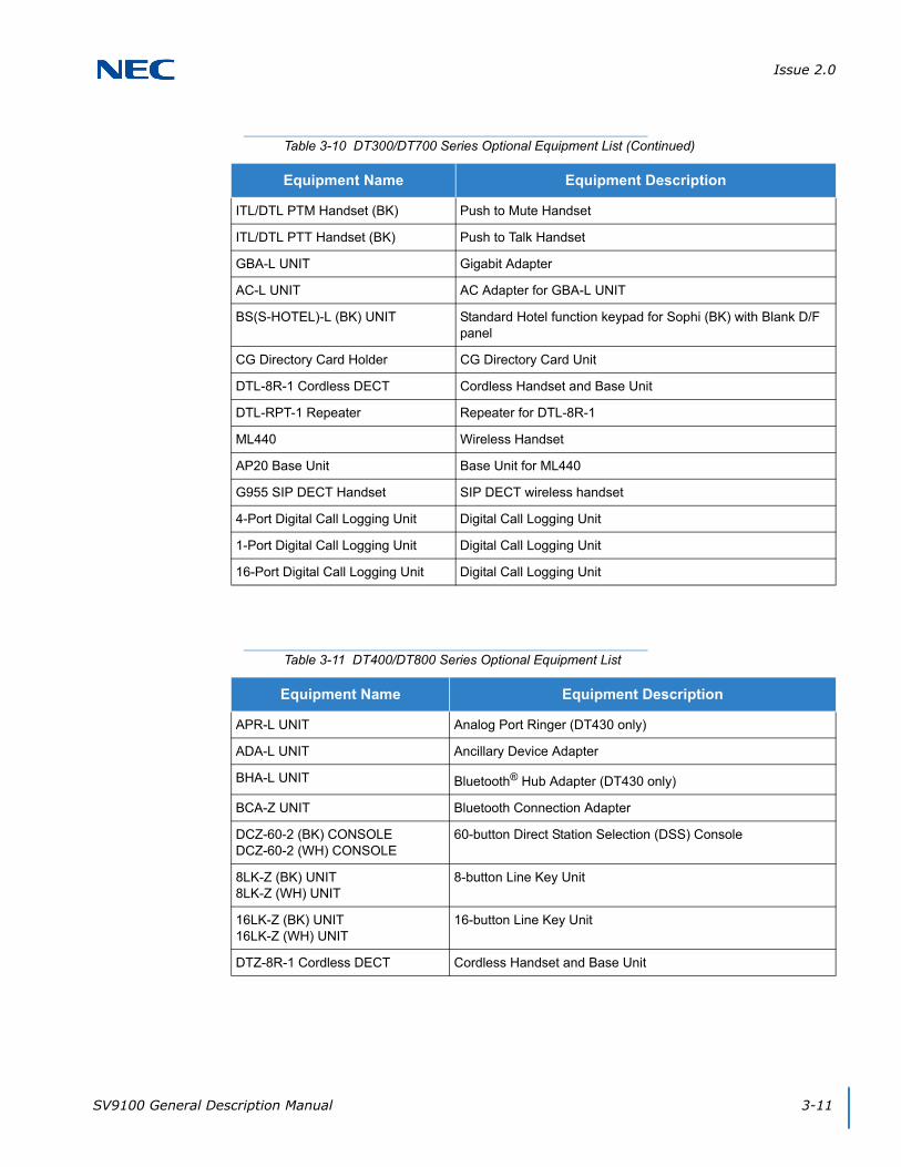
Issue 2.0
SV9100 General Description Manual 3-11
ITL/DTL PTM Handset (BK) Push to Mute Handset
ITL/DTL PTT Handset (BK) Push to Talk Handset
GBA-L UNIT Gigabit Adapter
AC-L UNIT AC Adapter for GBA-L UNIT
BS(S-HOTEL)-L (BK) UNIT Standard Hotel function keypad for Sophi (BK) with Blank D/F panel
CG Directory Card Holder CG Directory Card Unit
DTL-8R-1 Cordless DECT Cordless Handset and Base Unit
DTL-RPT-1 Repeater Repeater for DTL-8R-1
ML440 Wireless Handset
AP20 Base Unit Base Unit for ML440
G955 SIP DECT Handset SIP DECT wireless handset
4-Port Digital Call Logging Unit Digital Call Logging Unit
1-Port Digital Call Logging Unit Digital Call Logging Unit
16-Port Digital Call Logging Unit Digital Call Logging Unit
Table 3-11 DT400/DT800 Series Optional Equipment List
Equipment Name Equipment Description
APR-L UNIT Analog Port Ringer (DT430 only)
ADA-L UNIT Ancillary Device Adapter
BHA-L UNIT Bluetooth® Hub Adapter (DT430 only)
BCA-Z UNIT Bluetooth Connection Adapter
DCZ-60-2 (BK) CONSOLEDCZ-60-2 (WH) CONSOLE
60-button Direct Station Selection (DSS) Console
8LK-Z (BK) UNIT8LK-Z (WH) UNIT
8-button Line Key Unit
16LK-Z (BK) UNIT16LK-Z (WH) UNIT
16-button Line Key Unit
DTZ-8R-1 Cordless DECT Cordless Handset and Base Unit
Table 3-10 DT300/DT700 Series Optional Equipment List (Continued)
Equipment Name Equipment Description
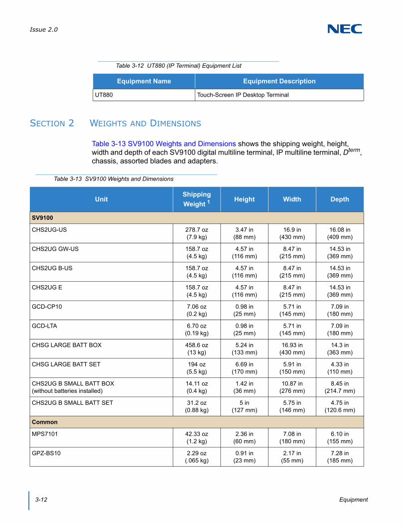
Issue 2.0
3-12 Equipment
SECTION 2 WEIGHTS AND DIMENSIONS
Table 3-13 SV9100 Weights and Dimensions shows the shipping weight, height, width and depth of each SV9100 digital multiline terminal, IP multiline terminal, Dterm, chassis, assorted blades and adapters.
Table 3-12 UT880 (IP Terminal) Equipment List
Equipment Name Equipment Description
UT880 Touch-Screen IP Desktop Terminal
Table 3-13 SV9100 Weights and Dimensions
UnitShipping
Weight 1Height Width Depth
SV9100
CHS2UG-US 278.7 oz(7.9 kg)
3.47 in(88 mm)
16.9 in(430 mm)
16.08 in(409 mm)
CHS2UG GW-US 158.7 oz(4.5 kg)
4.57 in(116 mm)
8.47 in(215 mm)
14.53 in(369 mm)
CHS2UG B-US 158.7 oz(4.5 kg)
4.57 in(116 mm)
8.47 in(215 mm)
14.53 in(369 mm)
CHS2UG E 158.7 oz(4.5 kg)
4.57 in(116 mm)
8.47 in(215 mm)
14.53 in(369 mm)
GCD-CP10 7.06 oz(0.2 kg)
0.98 in(25 mm)
5.71 in(145 mm)
7.09 in(180 mm)
GCD-LTA 6.70 oz(0.19 kg)
0.98 in(25 mm)
5.71 in(145 mm)
7.09 in(180 mm)
CHSG LARGE BATT BOX 458.6 oz(13 kg)
5.24 in(133 mm)
16.93 in(430 mm)
14.3 in(363 mm)
CHSG LARGE BATT SET 194 oz(5.5 kg)
6.69 in(170 mm)
5.91 in(150 mm)
4.33 in(110 mm)
CHS2UG B SMALL BATT BOX(without batteries installed)
14.11 oz(0.4 kg)
1.42 in(36 mm)
10.87 in(276 mm)
8.45 in(214.7 mm)
CHS2UG B SMALL BATT SET 31.2 oz(0.88 kg)
5 in(127 mm)
5.75 in(146 mm)
4.75 in(120.6 mm)
Common
MPS7101 42.33 oz(1.2 kg)
2.36 in(60 mm)
7.08 in(180 mm)
6.10 in(155 mm)
GPZ-BS10 2.29 oz(.065 kg)
0.91 in(23 mm)
2.17 in(55 mm)
7.28 in(185 mm)
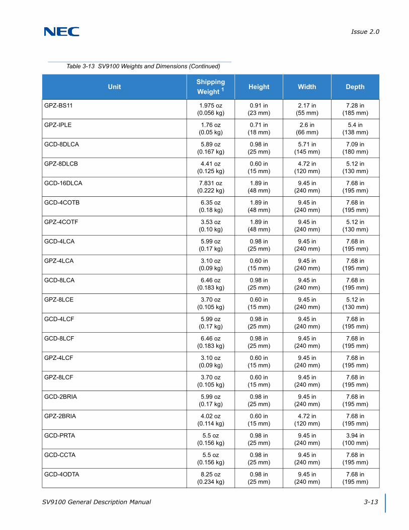
Issue 2.0
SV9100 General Description Manual 3-13
GPZ-BS11 1.975 oz(0.056 kg)
0.91 in(23 mm)
2.17 in(55 mm)
7.28 in(185 mm)
GPZ-IPLE 1.76 oz(0.05 kg)
0.71 in(18 mm)
2.6 in(66 mm)
5.4 in(138 mm)
GCD-8DLCA 5.89 oz(0.167 kg)
0.98 in(25 mm)
5.71 in(145 mm)
7.09 in(180 mm)
GPZ-8DLCB 4.41 oz(0.125 kg)
0.60 in(15 mm)
4.72 in(120 mm)
5.12 in(130 mm)
GCD-16DLCA 7.831 oz(0.222 kg)
1.89 in(48 mm)
9.45 in(240 mm)
7.68 in(195 mm)
GCD-4COTB 6.35 oz(0.18 kg)
1.89 in(48 mm)
9.45 in(240 mm)
7.68 in(195 mm)
GPZ-4COTF 3.53 oz(0.10 kg)
1.89 in(48 mm)
9.45 in(240 mm)
5.12 in(130 mm)
GCD-4LCA 5.99 oz(0.17 kg)
0.98 in(25 mm)
9.45 in(240 mm)
7.68 in(195 mm)
GPZ-4LCA 3.10 oz(0.09 kg)
0.60 in(15 mm)
9.45 in(240 mm)
7.68 in(195 mm)
GCD-8LCA 6.46 oz(0.183 kg)
0.98 in(25 mm)
9.45 in(240 mm)
7.68 in(195 mm)
GPZ-8LCE 3.70 oz(0.105 kg)
0.60 in(15 mm)
9.45 in(240 mm)
5.12 in(130 mm)
GCD-4LCF 5.99 oz(0.17 kg)
0.98 in(25 mm)
9.45 in(240 mm)
7.68 in(195 mm)
GCD-8LCF 6.46 oz(0.183 kg)
0.98 in(25 mm)
9.45 in(240 mm)
7.68 in(195 mm)
GPZ-4LCF 3.10 oz(0.09 kg)
0.60 in(15 mm)
9.45 in(240 mm)
7.68 in(195 mm)
GPZ-8LCF 3.70 oz(0.105 kg)
0.60 in(15 mm)
9.45 in(240 mm)
7.68 in(195 mm)
GCD-2BRIA 5.99 oz(0.17 kg)
0.98 in(25 mm)
9.45 in(240 mm)
7.68 in(195 mm)
GPZ-2BRIA 4.02 oz(0.114 kg)
0.60 in(15 mm)
4.72 in(120 mm)
7.68 in(195 mm)
GCD-PRTA 5.5 oz(0.156 kg)
0.98 in(25 mm)
9.45 in(240 mm)
3.94 in(100 mm)
GCD-CCTA 5.5 oz(0.156 kg)
0.98 in(25 mm)
9.45 in(240 mm)
7.68 in(195 mm)
GCD-4ODTA 8.25 oz(0.234 kg)
0.98 in(25 mm)
9.45 in(240 mm)
7.68 in(195 mm)
Table 3-13 SV9100 Weights and Dimensions (Continued)
UnitShipping
Weight 1Height Width Depth
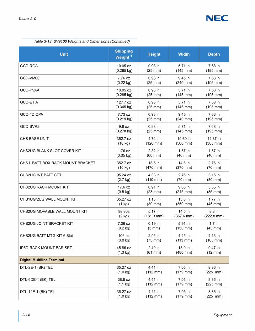
Issue 2.0
3-14 Equipment
GCD-RGA 10.05 oz(0.285 kg)
0.98 in(25 mm)
5.71 in(145 mm)
7.68 in(195 mm)
GCD-VM00 7.76 oz(0.22 kg)
0.98 in(25 mm)
9.45 in(240 mm)
7.68 in(195 mm)
GCD-PVAA 10.05 oz(0.285 kg)
0.98 in(25 mm)
5.71 in(145 mm)
7.68 in(195 mm)
GCD-ETIA 12.17 oz(0.345 kg)
0.98 in(25 mm)
5.71 in(145 mm)
7.68 in(195 mm)
GCD-4DIOPA 7.73 oz(0.219 kg)
0.98 in(25 mm)
9.45 in(240 mm)
7.68 in(195 mm)
GCD-SVR2 9.8 oz(0.278 kg)
0.98 in(25 mm)
5.71 in(145 mm)
7.68 in(195 mm)
CHS BASE UNIT 352.7 oz(10 kg)
4.72 in(120 mm)
19.69 in(500 mm)
14.37 in(365 mm)
CHS2UG BLANK SLOT COVER KIT 1.76 oz(0.05 kg)
2.32 in(60 mm)
1.57 in(40 mm)
1.57 in(40 mm)
CHS L BATT BOX RACK MOUNT BRACKET 352.7 oz(10 kg)
18.5 in(470 mm)
14.6 in(370 mm)
2.76 in(70 mm)
CHS2UG INT BATT SET 95.24 oz(2.7 kg)
4.33 in(110 mm)
2.76 in(70 mm)
3.15 in(80 mm)
CHS2UG RACK MOUNT KIT 17.6 oz(0.5 kg)
0.91 in(23 mm)
9.65 in(245 mm)
3.35 in(85 mm)
CHS1UG/2UG WALL MOUNT KIT 35.27 oz(1 kg)
1.18 in(30 mm)
13.8 in(350 mm)
1.77 in(45 mm)
CHS2UG MOVABLE WALL MOUNT KIT 98.8oz(2 kg)
5.17 in(131.3 mm)
14.5 in(367.6 mm)
8.8 in(222.8 mm)
CHS2UG JOINT BRACKET KIT 7.06 oz(0.2 kg)
0.19 in(3 mm)
5.91 in(150 mm)
1.7 in(43 mm)
CHS2UG BATT MTG KIT 6 Slot 106 oz(3.0 kg)
2.95 in(75 mm)
4.45 in(113 mm)
4.13 in(105 mm)
IP5D-RACK MOUNT BAR SET 45.86 oz(1.3 kg)
2.40 in(61 mm)
18.9 in(480 mm)
0.47 in(12 mm)
Digital Multiline Terminal
DTL-2E-1 (BK) TEL 35.27 oz(1.0 kg)
4.41 in(112 mm)
7.05 in(179 mm)
8.86 in(225 mm)
DTL-6DE-1 (BK) TEL 38.8 oz(1.1 kg)
4.41 in(112 mm)
7.05 in(179 mm)
8.86 in(225 mm)
DTL-12E-1 (BK) TEL 35.27 oz(1.0 kg)
4.41 in(112 mm)
7.05 in(179 mm)
8.86 in(225 mm)
Table 3-13 SV9100 Weights and Dimensions (Continued)
UnitShipping
Weight 1Height Width Depth
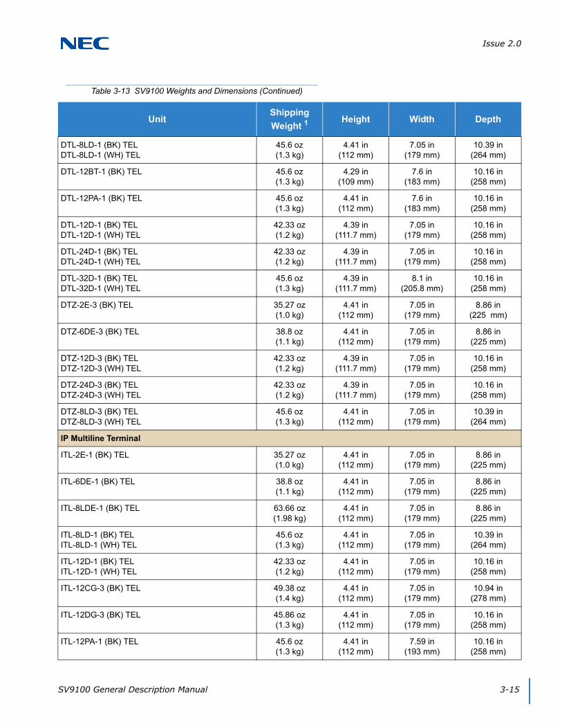
Issue 2.0
SV9100 General Description Manual 3-15
DTL-8LD-1 (BK) TELDTL-8LD-1 (WH) TEL
45.6 oz(1.3 kg)
4.41 in(112 mm)
7.05 in(179 mm)
10.39 in(264 mm)
DTL-12BT-1 (BK) TEL 45.6 oz(1.3 kg)
4.29 in(109 mm)
7.6 in(183 mm)
10.16 in(258 mm)
DTL-12PA-1 (BK) TEL 45.6 oz(1.3 kg)
4.41 in(112 mm)
7.6 in(183 mm)
10.16 in(258 mm)
DTL-12D-1 (BK) TELDTL-12D-1 (WH) TEL
42.33 oz(1.2 kg)
4.39 in(111.7 mm)
7.05 in(179 mm)
10.16 in(258 mm)
DTL-24D-1 (BK) TELDTL-24D-1 (WH) TEL
42.33 oz(1.2 kg)
4.39 in(111.7 mm)
7.05 in(179 mm)
10.16 in(258 mm)
DTL-32D-1 (BK) TELDTL-32D-1 (WH) TEL
45.6 oz(1.3 kg)
4.39 in(111.7 mm)
8.1 in(205.8 mm)
10.16 in(258 mm)
DTZ-2E-3 (BK) TEL 35.27 oz(1.0 kg)
4.41 in(112 mm)
7.05 in(179 mm)
8.86 in(225 mm)
DTZ-6DE-3 (BK) TEL 38.8 oz(1.1 kg)
4.41 in(112 mm)
7.05 in(179 mm)
8.86 in(225 mm)
DTZ-12D-3 (BK) TELDTZ-12D-3 (WH) TEL
42.33 oz(1.2 kg)
4.39 in(111.7 mm)
7.05 in(179 mm)
10.16 in(258 mm)
DTZ-24D-3 (BK) TELDTZ-24D-3 (WH) TEL
42.33 oz(1.2 kg)
4.39 in(111.7 mm)
7.05 in(179 mm)
10.16 in(258 mm)
DTZ-8LD-3 (BK) TELDTZ-8LD-3 (WH) TEL
45.6 oz(1.3 kg)
4.41 in(112 mm)
7.05 in(179 mm)
10.39 in(264 mm)
IP Multiline Terminal
ITL-2E-1 (BK) TEL 35.27 oz(1.0 kg)
4.41 in(112 mm)
7.05 in(179 mm)
8.86 in(225 mm)
ITL-6DE-1 (BK) TEL 38.8 oz(1.1 kg)
4.41 in(112 mm)
7.05 in(179 mm)
8.86 in(225 mm)
ITL-8LDE-1 (BK) TEL 63.66 oz(1.98 kg)
4.41 in(112 mm)
7.05 in(179 mm)
8.86 in(225 mm)
ITL-8LD-1 (BK) TELITL-8LD-1 (WH) TEL
45.6 oz(1.3 kg)
4.41 in(112 mm)
7.05 in(179 mm)
10.39 in(264 mm)
ITL-12D-1 (BK) TELITL-12D-1 (WH) TEL
42.33 oz(1.2 kg)
4.41 in(112 mm)
7.05 in(179 mm)
10.16 in(258 mm)
ITL-12CG-3 (BK) TEL 49.38 oz(1.4 kg)
4.41 in(112 mm)
7.05 in(179 mm)
10.94 in(278 mm)
ITL-12DG-3 (BK) TEL 45.86 oz(1.3 kg)
4.41 in(112 mm)
7.05 in(179 mm)
10.16 in(258 mm)
ITL-12PA-1 (BK) TEL 45.6 oz(1.3 kg)
4.41 in(112 mm)
7.59 in(193 mm)
10.16 in(258 mm)
Table 3-13 SV9100 Weights and Dimensions (Continued)
UnitShipping
Weight 1Height Width Depth
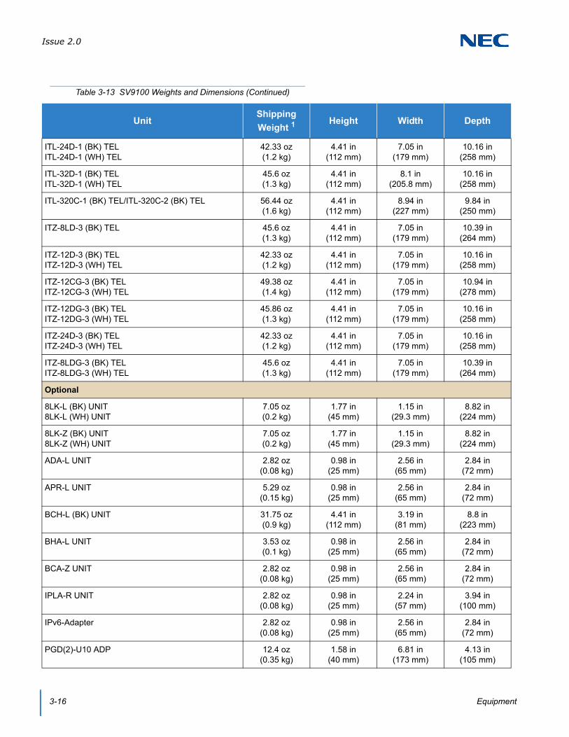
Issue 2.0
3-16 Equipment
ITL-24D-1 (BK) TELITL-24D-1 (WH) TEL
42.33 oz(1.2 kg)
4.41 in(112 mm)
7.05 in(179 mm)
10.16 in(258 mm)
ITL-32D-1 (BK) TELITL-32D-1 (WH) TEL
45.6 oz(1.3 kg)
4.41 in(112 mm)
8.1 in(205.8 mm)
10.16 in(258 mm)
ITL-320C-1 (BK) TEL/ITL-320C-2 (BK) TEL 56.44 oz(1.6 kg)
4.41 in(112 mm)
8.94 in(227 mm)
9.84 in(250 mm)
ITZ-8LD-3 (BK) TEL 45.6 oz(1.3 kg)
4.41 in(112 mm)
7.05 in(179 mm)
10.39 in(264 mm)
ITZ-12D-3 (BK) TELITZ-12D-3 (WH) TEL
42.33 oz(1.2 kg)
4.41 in(112 mm)
7.05 in(179 mm)
10.16 in(258 mm)
ITZ-12CG-3 (BK) TELITZ-12CG-3 (WH) TEL
49.38 oz(1.4 kg)
4.41 in(112 mm)
7.05 in(179 mm)
10.94 in(278 mm)
ITZ-12DG-3 (BK) TELITZ-12DG-3 (WH) TEL
45.86 oz(1.3 kg)
4.41 in(112 mm)
7.05 in(179 mm)
10.16 in(258 mm)
ITZ-24D-3 (BK) TELITZ-24D-3 (WH) TEL
42.33 oz(1.2 kg)
4.41 in(112 mm)
7.05 in(179 mm)
10.16 in(258 mm)
ITZ-8LDG-3 (BK) TELITZ-8LDG-3 (WH) TEL
45.6 oz(1.3 kg)
4.41 in(112 mm)
7.05 in(179 mm)
10.39 in(264 mm)
Optional
8LK-L (BK) UNIT8LK-L (WH) UNIT
7.05 oz(0.2 kg)
1.77 in(45 mm)
1.15 in(29.3 mm)
8.82 in(224 mm)
8LK-Z (BK) UNIT8LK-Z (WH) UNIT
7.05 oz(0.2 kg)
1.77 in(45 mm)
1.15 in(29.3 mm)
8.82 in(224 mm)
ADA-L UNIT 2.82 oz(0.08 kg)
0.98 in(25 mm)
2.56 in(65 mm)
2.84 in(72 mm)
APR-L UNIT 5.29 oz(0.15 kg)
0.98 in(25 mm)
2.56 in(65 mm)
2.84 in(72 mm)
BCH-L (BK) UNIT 31.75 oz(0.9 kg)
4.41 in(112 mm)
3.19 in(81 mm)
8.8 in(223 mm)
BHA-L UNIT 3.53 oz(0.1 kg)
0.98 in(25 mm)
2.56 in(65 mm)
2.84 in(72 mm)
BCA-Z UNIT 2.82 oz(0.08 kg)
0.98 in(25 mm)
2.56 in(65 mm)
2.84 in(72 mm)
IPLA-R UNIT 2.82 oz(0.08 kg)
0.98 in(25 mm)
2.24 in(57 mm)
3.94 in(100 mm)
IPv6-Adapter 2.82 oz(0.08 kg)
0.98 in(25 mm)
2.56 in(65 mm)
2.84 in(72 mm)
PGD(2)-U10 ADP 12.4 oz(0.35 kg)
1.58 in(40 mm)
6.81 in(173 mm)
4.13 in(105 mm)
Table 3-13 SV9100 Weights and Dimensions (Continued)
UnitShipping
Weight 1Height Width Depth
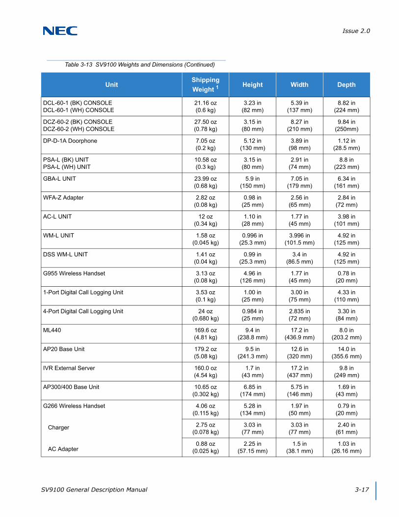
Issue 2.0
SV9100 General Description Manual 3-17
DCL-60-1 (BK) CONSOLEDCL-60-1 (WH) CONSOLE
21.16 oz(0.6 kg)
3.23 in(82 mm)
5.39 in(137 mm)
8.82 in(224 mm)
DCZ-60-2 (BK) CONSOLEDCZ-60-2 (WH) CONSOLE
27.50 oz(0.78 kg)
3.15 in(80 mm)
8.27 in(210 mm)
9.84 in(250mm)
DP-D-1A Doorphone 7.05 oz(0.2 kg)
5.12 in(130 mm)
3.89 in(98 mm)
1.12 in(28.5 mm)
PSA-L (BK) UNITPSA-L (WH) UNIT
10.58 oz(0.3 kg)
3.15 in(80 mm)
2.91 in(74 mm)
8.8 in(223 mm)
GBA-L UNIT 23.99 oz(0.68 kg)
5.9 in(150 mm)
7.05 in(179 mm)
6.34 in(161 mm)
WFA-Z Adapter 2.82 oz(0.08 kg)
0.98 in(25 mm)
2.56 in(65 mm)
2.84 in(72 mm)
AC-L UNIT 12 oz(0.34 kg)
1.10 in(28 mm)
1.77 in(45 mm)
3.98 in(101 mm)
WM-L UNIT 1.58 oz(0.045 kg)
0.996 in(25.3 mm)
3.996 in(101.5 mm)
4.92 in(125 mm)
DSS WM-L UNIT 1.41 oz(0.04 kg)
0.99 in(25.3 mm)
3.4 in(86.5 mm)
4.92 in(125 mm)
G955 Wireless Handset 3.13 oz(0.08 kg)
4.96 in(126 mm)
1.77 in(45 mm)
0.78 in(20 mm)
1-Port Digital Call Logging Unit 3.53 oz(0.1 kg)
1.00 in(25 mm)
3.00 in(75 mm)
4.33 in(110 mm)
4-Port Digital Call Logging Unit 24 oz(0.680 kg)
0.984 in(25 mm)
2.835 in(72 mm)
3.30 in(84 mm)
ML440 169.6 oz(4.81 kg)
9.4 in(238.8 mm)
17.2 in(436.9 mm)
8.0 in(203.2 mm)
AP20 Base Unit 179.2 oz(5.08 kg)
9.5 in(241.3 mm)
12.6 in(320 mm)
14.0 in(355.6 mm)
IVR External Server 160.0 oz(4.54 kg)
1.7 in(43 mm)
17.2 in(437 mm)
9.8 in(249 mm)
AP300/400 Base Unit 10.65 oz(0.302 kg)
6.85 in(174 mm)
5.75 in(146 mm)
1.69 in(43 mm)
G266 Wireless Handset
Charger
AC Adapter
4.06 oz(0.115 kg)
5.28 in(134 mm)
1.97 in(50 mm)
0.79 in(20 mm)
2.75 oz(0.078 kg)
3.03 in(77 mm)
3.03 in(77 mm)
2.40 in(61 mm)
0.88 oz(0.025 kg)
2.25 in(57.15 mm)
1.5 in(38.1 mm)
1.03 in(26.16 mm)
Table 3-13 SV9100 Weights and Dimensions (Continued)
UnitShipping
Weight 1Height Width Depth
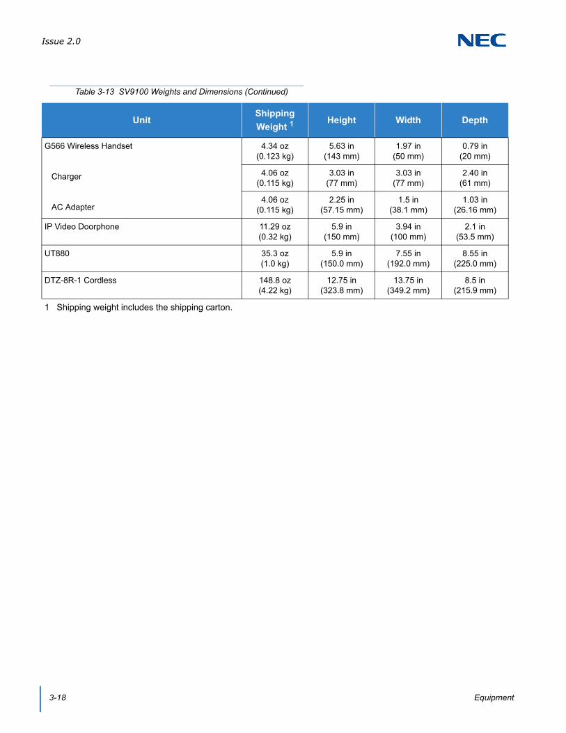
Issue 2.0
3-18 Equipment
G566 Wireless Handset
Charger
AC Adapter
4.34 oz(0.123 kg)
5.63 in(143 mm)
1.97 in(50 mm)
0.79 in(20 mm)
4.06 oz(0.115 kg)
3.03 in(77 mm)
3.03 in(77 mm)
2.40 in(61 mm)
4.06 oz(0.115 kg)
2.25 in(57.15 mm)
1.5 in(38.1 mm)
1.03 in(26.16 mm)
IP Video Doorphone 11.29 oz(0.32 kg)
5.9 in(150 mm)
3.94 in(100 mm)
2.1 in(53.5 mm)
UT880 35.3 oz(1.0 kg)
5.9 in(150.0 mm)
7.55 in(192.0 mm)
8.55 in(225.0 mm)
DTZ-8R-1 Cordless 148.8 oz(4.22 kg)
12.75 in(323.8 mm)
13.75 in(349.2 mm)
8.5 in(215.9 mm)
1 Shipping weight includes the shipping carton.
Table 3-13 SV9100 Weights and Dimensions (Continued)
UnitShipping
Weight 1Height Width Depth
SV9100 General Description Manual 4-1
Chapter 4
UNIVERGE® SV9100
Installation, Programming, and Maintenance Overview
SECTION 1 INSTALLATION AND TECHNICAL CONSIDERATIONS
The compact UNIVERGE SV9100 chassis and front loading blades make installation easy. The system can be wall, floor or rack mounted as desired. The GCD-CP10 (Central Processing Unit) performs a number of functions and operations under the control of software programs on the GCD-CP10 package. These programs can be easily upgraded as new features and functionalities are added to the system.
The following functionalities are provided on the GCD-CP10:
Call Control Server
Conference Bridge Server
Voice Mail Server
SIP Server
RTP (Real-Time Transport Protocol) Forwarding
VoCoder Conversion
The GCD-CP10 uses a 32-bit industrial standard CPU and associated memories to control the system. The GCD-CP10 bus is connected to the backplane of the chassis and provides control for other packages installed in the UNIVERGE SV9100 chassis. The GCD-CP10 is installed in the GCD-CP10 slot reserved for it in this chassis (no other board works in this slot).
The Tone Generator provides various audio signals such as dial tone, reorder tone, busy tone and DTMF (Dual Tone Multifrequency) signaling, which comply with industrial standard tone plans. The DTMF tone sender can resend the DTMF tone signal to a distant-end through the trunk or line circuits. The DTMF tone receiver can receive DTMF signals sent from industry standard telephones or distant locations.
The MF (Multifrequency) signal sender resends toll type multifrequency signals to a central office allowing for emergency (E911) ability.
Caller ID Receiver receives Caller ID signals from the central office and converts those signals for display on the UNIVERGE SV9100 telephones. Caller ID Generator generates industry standard Caller ID signals, based on the digital signal delivered from the CCPU and transmitted to the distant-end.
Issue 2.0
4-2 Installation, Programming, and Maintenance Overview
UNIVERGE SV9100 provides 64 conference circuits for conference calling.
The Power supply unit and the battery backup unit are installed in the SV8100 chassis and allow easy connection to extra battery backup units. All circuits installed in the chassis are located on blades that plug into the slots.
Connecting voice and data between more than one chassis is provided by a bus cable between the basic and expansion SV9100 chassis. Voice and data are transmitted between the chassis using GPZ-BS10 and GPZ-BS11 blades in the UNIVERGE SV9100 system.
Connecting the system to telephones, outside lines or other external devices is made using telephone cable connectors. A music source for Music on Hold is connected by standard audio equipment plugs.
Universal slots maximize flexibility by allowing installation of any blade in any interface slot (except slot 1 of chassis 1 reserved for the GCD-CP10). Full use of each chassis, before adding another, reduces hardware requirements.
A Resident System Program is provided when the system first receives power. The GCD-CP10 scans the chassis and recognizes the blades and multiline terminals that are connected to the system. Standard (default) values are assigned in the System Program for all system and device parameters to allow the system to operate immediately after initialization, before programming is done.
The assignments provided by the Resident System Program can be altered to fit the requirements of a particular installation. Changing programming assignments is the function of multiline terminals or a personal computer. When programming from a multiline terminal, Flexible Line keys and the dial pad are used to enter new values, and the display provides the necessary information for programming.
Multiline Terminals and Single Line Telephones
A variety of telephones can be connected to satisfy the requirements of a particular installation. All multiline terminals are fully modular and are powered from the central unit. Cabling is twisted 1-pair for proprietary multiline terminals and single line telephones.
SECTION 2 PROGRAMMING
From Multiline Terminals
Programming is done using DTL-6DE-1 TEL, DTL-12/24/32D-1 TEL, DTL-8LD-1 TEL, DTZ-6DE-3 TEL, DTZ 8LD-3 TEL, DTZ-12/24/32D-3 TEL, ITL-6DE-1 TEL, ITL-12/24/32D-1 TEL, ITL-8LD-1 TEL, ITL-320C-1 TEL, ITL-320C-2 TEL, ITZ-8/12/24/32D-3 TEL, ITZ-8LDG-3 TEL, ITZ-12CG/DG TEL multiline terminals.
Issue 2.0
SV9100 General Description Manual 4-3
When a programming multiline terminal is off-line in the Program Mode, the rest of the system continues to function. Most program changes can be entered anytime, but some changes take effect only when the affected stations and circuits are idle. This avoids disrupting calls in progress.
PC Programming
System data can be transferred to/from a disk for backup. The System Program End User software allows end users to program several features for their multiline terminals, such as: Line Key Assignment, Telephone Names, Zone Paging Groups, or various timers.
Battery Backup
The battery on the GCD-CP10 retains the Clock/Calendar and Last Number Redial (LNR) buffers for each station when the GCD-CP10 encounters a power loss. When the battery is fully charged, the settings are retained for approximately three years. The Lithium (CR2032) battery should be replaced every two years. The system programmed memory (Customer Database) is stored in nonvolatile Memory and can be erased only by a First Initialization.
The batteries, located in the SV9100 chassis, support system operation for up to 30 minutes during a power outage.
User Programmable Features
Multiline terminal users can program the following features from their station:
Ringing Line Preference
Feature Access and/or One-Touch keys (e.g., Speed Dial or Direct Station Selection)
Speed Dial
Multiline terminals without programmable One-Touch keys and single line telephones can be used to program Station Speed Dial memories. Attendant Positions can be used to program System Speed Dial memories and the System Clock/Calendar.
SECTION 3 MAINTENANCE
Installing Interface Blades without Disrupting Ongoing Calls
Each interface and optional blade has an LED indication of power status. An interface blade (except the GCD-CP10) with this switch OFF can be removed or installed with the system power on.
The combination of status indication and blade replacement with power on allows the maintenance technician to replace suspect circuits without disrupting ongoing calls.
Issue 2.0
4-4 Installation, Programming, and Maintenance Overview
Up/Down Load of Data
Using PC Programming, Station Speed Dial data, System Speed Dial data, and all System Data can be transferred from/to a PC. The Up/Down Load may be accomplished from a local or remote location.
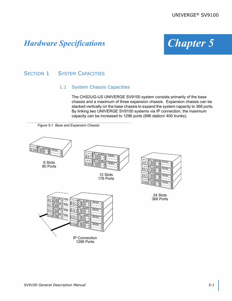
SV9100 General Description Manual 5-1
Chapter 5
UNIVERGE® SV9100
Hardware Specifications
SECTION 1 SYSTEM CAPACITIES
1.1 System Chassis Capacities
The CHS2UG-US UNIVERGE SV9100 system consists primarily of the base chassis and a maximum of three expansion chassis. Expansion chassis can be stacked vertically on the base chassis to expand the system capacity to 368 ports. By linking two UNIVERGE SV9100 systems via IP connection, the maximum capacity can be increased to 1296 ports (896 station/ 400 trunks).
Figure 5-1 Base and Expansion Chassis
6 Slots80 Ports
12 Slots176 Ports
24 Slots368 Ports
IP Connection1296 Ports
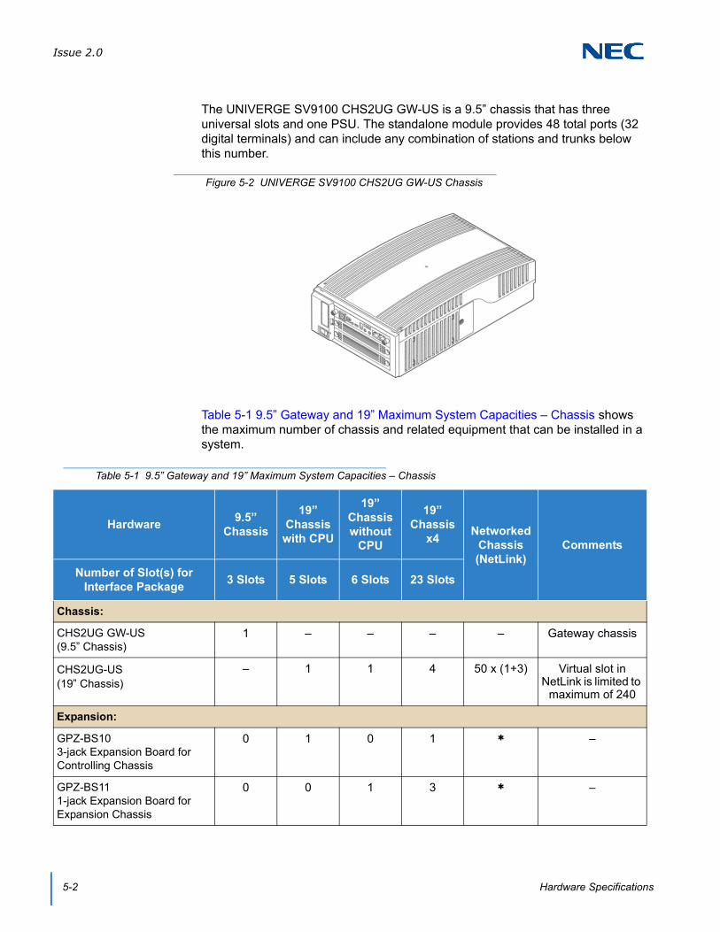
Issue 2.0
5-2 Hardware Specifications
The UNIVERGE SV9100 CHS2UG GW-US is a 9.5” chassis that has three universal slots and one PSU. The standalone module provides 48 total ports (32 digital terminals) and can include any combination of stations and trunks below this number.
Table 5-1 9.5” Gateway and 19” Maximum System Capacities – Chassis shows the maximum number of chassis and related equipment that can be installed in a system.
Figure 5-2 UNIVERGE SV9100 CHS2UG GW-US Chassis
Table 5-1 9.5” Gateway and 19” Maximum System Capacities – Chassis
Hardware9.5”
Chassis
19” Chassis with CPU
19” Chassis without
CPU
19” Chassis
x4Networked
Chassis (NetLink)
Comments
Number of Slot(s) for Interface Package
3 Slots 5 Slots 6 Slots 23 Slots
Chassis:
CHS2UG GW-US(9.5” Chassis)
1 – – – – Gateway chassis
CHS2UG-US(19” Chassis)
– 1 1 4 50 x (1+3) Virtual slot in NetLink is limited to
maximum of 240
Expansion:
GPZ-BS103-jack Expansion Board for Controlling Chassis
0 1 0 1 –
GPZ-BS111-jack Expansion Board for Expansion Chassis
0 0 1 3 –
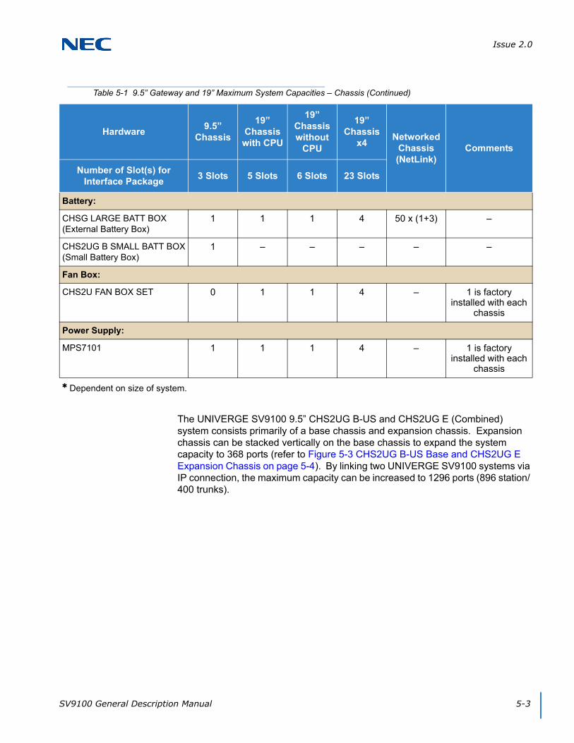
Issue 2.0
SV9100 General Description Manual 5-3
The UNIVERGE SV9100 9.5” CHS2UG B-US and CHS2UG E (Combined) system consists primarily of a base chassis and expansion chassis. Expansion chassis can be stacked vertically on the base chassis to expand the system capacity to 368 ports (refer to Figure 5-3 CHS2UG B-US Base and CHS2UG E Expansion Chassis on page 5-4). By linking two UNIVERGE SV9100 systems via IP connection, the maximum capacity can be increased to 1296 ports (896 station/ 400 trunks).
Battery:
CHSG LARGE BATT BOX(External Battery Box)
1 1 1 4 50 x (1+3) –
CHS2UG B SMALL BATT BOX(Small Battery Box)
1 – – – – –
Fan Box:
CHS2U FAN BOX SET 0 1 1 4 – 1 is factory installed with each
chassis
Power Supply:
MPS7101 1 1 1 4 – 1 is factory installed with each
chassis
Dependent on size of system.
Table 5-1 9.5” Gateway and 19” Maximum System Capacities – Chassis (Continued)
Hardware9.5”
Chassis
19” Chassis with CPU
19” Chassis without
CPU
19” Chassis
x4Networked
Chassis (NetLink)
Comments
Number of Slot(s) for Interface Package
3 Slots 5 Slots 6 Slots 23 Slots
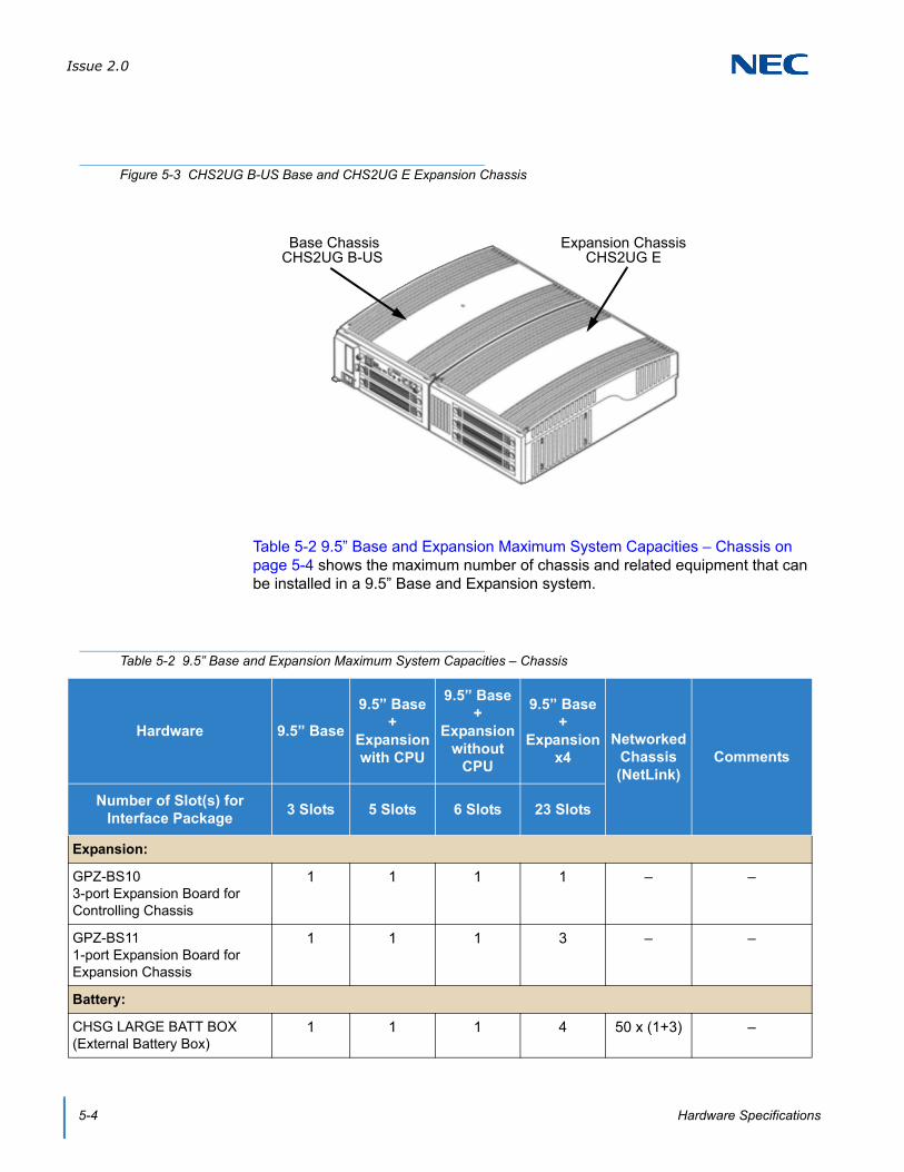
Issue 2.0
5-4 Hardware Specifications
Table 5-2 9.5” Base and Expansion Maximum System Capacities – Chassis on page 5-4 shows the maximum number of chassis and related equipment that can be installed in a 9.5” Base and Expansion system.
Figure 5-3 CHS2UG B-US Base and CHS2UG E Expansion Chassis
Expansion ChassisCHS2UG E
Base ChassisCHS2UG B-US
Table 5-2 9.5” Base and Expansion Maximum System Capacities – Chassis
Hardware 9.5” Base
9.5” Base +
Expansion with CPU
9.5” Base +
Expansion without
CPU
9.5” Base +
Expansionx4
Networked Chassis (NetLink)
Comments
Number of Slot(s) for Interface Package
3 Slots 5 Slots 6 Slots 23 Slots
Expansion:
GPZ-BS103-port Expansion Board for Controlling Chassis
1 1 1 1 – –
GPZ-BS111-port Expansion Board for Expansion Chassis
1 1 1 3 – –
Battery:
CHSG LARGE BATT BOX(External Battery Box)
1 1 1 4 50 x (1+3) –
Issue 2.0
SV9100 General Description Manual 5-5
1.2 System Blade Capacities
Table 5-3 SV9100 Maximum 9.5” Gateway and 19” System Capacities – Blades and Table 5-4 SV9100 Maximum 9.5” Base and Expansion System Capacities – Blades on page 5-8 show the maximum number for each blade that can be installed in a system.
This is determined by the maximum blade configuration allowed. When installing single line sets, DISA, or tie lines, CPU circuits must be allocated for DTMF receivers. To install single line sets with CO/PBX line access, or when installing immediate-start tie lines, CPU circuits must be allocated for dial tone detection.
CHS2UG B SMALL BATT BOX(Small Battery Box)
1 1 1 4 50 x (1+3) –
Power Supply:
MPS7101 1 1 1 4 – 1 is factory installed with each chassis
Table 5-2 9.5” Base and Expansion Maximum System Capacities – Chassis (Continued)
Hardware 9.5” Base
9.5” Base +
Expansion with CPU
9.5” Base +
Expansion without
CPU
9.5” Base +
Expansionx4
Networked Chassis (NetLink)
Comments
Number of Slot(s) for Interface Package
3 Slots 5 Slots 6 Slots 23 Slots
Table 5-3 SV9100 Maximum 9.5” Gateway and 19” System Capacities – Blades
Hardware9.5”
Chassis
19” Chassis with CPU
19” Chassis without
CPU
19” Chassis
x4Networked
Chassis (NetLink)
Comments
Number of Slot(s) for Interface Package
3 Slots 5 Slots 6 Slots 23 Slots
Common Control Blades:
GCD-CP10 1 1 0 1 50 –
GPZ-IPLE(VoIP Daughter Board)
1 1 0 1 50 This unit provides 256 VOIP Gateway
channels
GCD-SVR2(Server Blade)
1 1 1 1 1
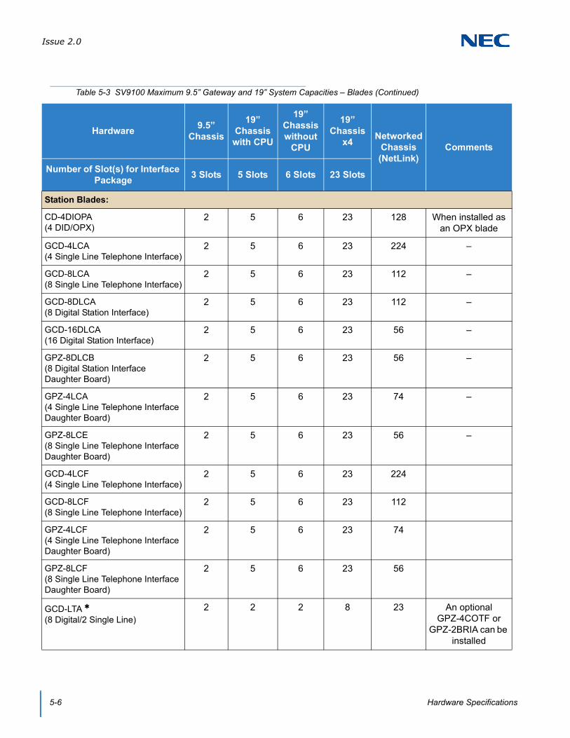
Issue 2.0
5-6 Hardware Specifications
Station Blades:
CD-4DIOPA(4 DID/OPX)
2 5 6 23 128 When installed as an OPX blade
GCD-4LCA(4 Single Line Telephone Interface)
2 5 6 23 224 –
GCD-8LCA(8 Single Line Telephone Interface)
2 5 6 23 112 –
GCD-8DLCA(8 Digital Station Interface)
2 5 6 23 112 –
GCD-16DLCA(16 Digital Station Interface)
2 5 6 23 56 –
GPZ-8DLCB(8 Digital Station Interface Daughter Board)
2 5 6 23 56 –
GPZ-4LCA(4 Single Line Telephone Interface Daughter Board)
2 5 6 23 74 –
GPZ-8LCE(8 Single Line Telephone Interface Daughter Board)
2 5 6 23 56 –
GCD-4LCF(4 Single Line Telephone Interface)
2 5 6 23 224
GCD-8LCF(8 Single Line Telephone Interface)
2 5 6 23 112
GPZ-4LCF(4 Single Line Telephone Interface Daughter Board)
2 5 6 23 74
GPZ-8LCF(8 Single Line Telephone Interface Daughter Board)
2 5 6 23 56
GCD-LTA
(8 Digital/2 Single Line)
2 2 2 8 23 An optional GPZ-4COTF or
GPZ-2BRIA can be installed
Table 5-3 SV9100 Maximum 9.5” Gateway and 19” System Capacities – Blades (Continued)
Hardware9.5”
Chassis
19” Chassis with CPU
19” Chassis without
CPU
19” Chassis
x4Networked
Chassis (NetLink)
Comments
Number of Slot(s) for Interface Package
3 Slots 5 Slots 6 Slots 23 Slots
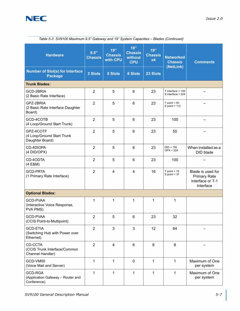
Issue 2.0
SV9100 General Description Manual 5-7
Trunk Blades:
GCD-2BRIA(2 Basic Rate Interface)
2 5 6 23 T interface = 100S interface = 224
–
GPZ-2BRIA(2 Basic Rate Interface Daughter Board)
2 5 6 23 T point = 50S point = 112
–
GCD-4COTB(4 Loop/Ground Start Trunk)
2 5 6 23 100 –
GPZ-4COTF(4 Loop/Ground Start Trunk Daughter Board)
2 5 6 23 50 –
CD-4DIOPA(4 DID/OPX)
2 5 6 23 DID = 100OPX = 224
When installed as a DID blade
CD-4ODTA(4 E&M)
2 5 6 23 100 –
GCD-PRTA(1 Primary Rate Interface)
2 4 4 16 T point = 16S point = 37
Blade is used for Primary Rate
Interface or T-1 Interface
Optional Blades:
GCD-PVAA(Interactive Voice Response,PVA PMS)
1 1 1 1 1
GCD-PVAA(CCIS Point-to-Multipoint)
2 5 6 23 32
GCD-ETIA(Switching Hub with Power over Ethernet)
2 3 3 12 64 –
CD-CCTA(CCIS Trunk Interface/Common Channel Handler)
2 4 6 8 8 –
GCD-VM00(Voice Mail and Server)
1 1 0 1 1 Maximum of One per system
GCD-RGA(Application Gateway – Router and Conference)
1 1 1 1 1 Maximum of One per system
Table 5-3 SV9100 Maximum 9.5” Gateway and 19” System Capacities – Blades (Continued)
Hardware9.5”
Chassis
19” Chassis with CPU
19” Chassis without
CPU
19” Chassis
x4Networked
Chassis (NetLink)
Comments
Number of Slot(s) for Interface Package
3 Slots 5 Slots 6 Slots 23 Slots
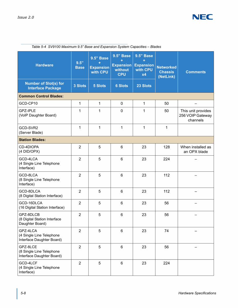
Issue 2.0
5-8 Hardware Specifications
Table 5-4 SV9100 Maximum 9.5” Base and Expansion System Capacities – Blades
Hardware9.5” Base
9.5” Base +
Expansion with CPU
9.5” Base +
Expansion without
CPU
9.5” Base +
Expansion with CPU
x4
Networked Chassis (NetLink)
Comments
Number of Slot(s) for Interface Package
3 Slots 5 Slots 6 Slots 23 Slots
Common Control Blades:
GCD-CP10 1 1 0 1 50 –
GPZ-IPLE(VoIP Daughter Board)
1 1 0 1 50 This unit provides 256 VOIP Gateway
channels
GCD-SVR2(Server Blade)
1 1 1 1 1
Station Blades:
CD-4DIOPA(4 DID/OPX)
2 5 6 23 128 When installed as an OPX blade
GCD-4LCA(4 Single Line Telephone Interface)
2 5 6 23 224 –
GCD-8LCA(8 Single Line Telephone Interface)
2 5 6 23 112 –
GCD-8DLCA(8 Digital Station Interface)
2 5 6 23 112 –
GCD-16DLCA(16 Digital Station Interface)
2 5 6 23 56 –
GPZ-8DLCB(8 Digital Station Interface Daughter Board)
2 5 6 23 56 –
GPZ-4LCA(4 Single Line Telephone Interface Daughter Board)
2 5 6 23 74 –
GPZ-8LCE(8 Single Line Telephone Interface Daughter Board)
2 5 6 23 56 –
GCD-4LCF(4 Single Line Telephone Interface)
2 5 6 23 224
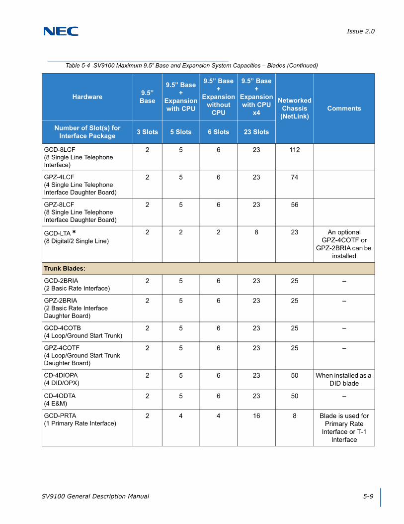
Issue 2.0
SV9100 General Description Manual 5-9
GCD-8LCF(8 Single Line Telephone Interface)
2 5 6 23 112
GPZ-4LCF(4 Single Line Telephone Interface Daughter Board)
2 5 6 23 74
GPZ-8LCF(8 Single Line Telephone Interface Daughter Board)
2 5 6 23 56
GCD-LTA
(8 Digital/2 Single Line)2 2 2 8 23 An optional
GPZ-4COTF or GPZ-2BRIA can be
installed
Trunk Blades:
GCD-2BRIA(2 Basic Rate Interface)
2 5 6 23 25 –
GPZ-2BRIA(2 Basic Rate Interface Daughter Board)
2 5 6 23 25 –
GCD-4COTB(4 Loop/Ground Start Trunk)
2 5 6 23 25 –
GPZ-4COTF(4 Loop/Ground Start Trunk Daughter Board)
2 5 6 23 25 –
CD-4DIOPA(4 DID/OPX)
2 5 6 23 50 When installed as a DID blade
CD-4ODTA(4 E&M)
2 5 6 23 50 –
GCD-PRTA(1 Primary Rate Interface)
2 4 4 16 8 Blade is used for Primary Rate
Interface or T-1 Interface
Table 5-4 SV9100 Maximum 9.5” Base and Expansion System Capacities – Blades (Continued)
Hardware9.5” Base
9.5” Base +
Expansion with CPU
9.5” Base +
Expansion without
CPU
9.5” Base +
Expansion with CPU
x4
Networked Chassis (NetLink)
Comments
Number of Slot(s) for Interface Package
3 Slots 5 Slots 6 Slots 23 Slots
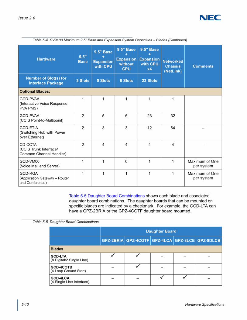
Issue 2.0
5-10 Hardware Specifications
Table 5-5 Daughter Board Combinations shows each blade and associated daughter board combinations. The daughter boards that can be mounted on specific blades are indicated by a checkmark. For example, the GCD-LTA can have a GPZ-2BRIA or the GPZ-4COTF daughter board mounted.
Optional Blades:
GCD-PVAA(Interactive Voice Response,PVA PMS)
1 1 1 1 1
GCD-PVAA(CCIS Point-to-Multipoint)
2 5 6 23 32
GCD-ETIA(Switching Hub with Power over Ethernet)
2 3 3 12 64 –
CD-CCTA(CCIS Trunk Interface/Common Channel Handler)
2 4 4 4 4 –
GCD-VM00(Voice Mail and Server)
1 1 0 1 1 Maximum of One per system
GCD-RGA(Application Gateway – Router and Conference)
1 1 1 1 1 Maximum of One per system
Table 5-4 SV9100 Maximum 9.5” Base and Expansion System Capacities – Blades (Continued)
Hardware9.5” Base
9.5” Base +
Expansion with CPU
9.5” Base +
Expansion without
CPU
9.5” Base +
Expansion with CPU
x4
Networked Chassis (NetLink)
Comments
Number of Slot(s) for Interface Package
3 Slots 5 Slots 6 Slots 23 Slots
Table 5-5 Daughter Board Combinations
Daughter Board
GPZ-2BRIA GPZ-4COTF GPZ-4LCA GPZ-8LCE GPZ-8DLCB
Blades
GCD-LTA(8 Digital/2 Single Line)
– – –
GCD-4COTB(4 Loop Ground Start)
– – – –
GCD-4LCA(4 Single Line Interface)
– – –
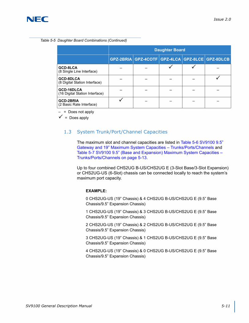
Issue 2.0
SV9100 General Description Manual 5-11
1.3 System Trunk/Port/Channel Capacities
The maximum slot and channel capacities are listed in Table 5-6 SV9100 9.5” Gateway and 19” Maximum System Capacities – Trunks/Ports/Channels and Table 5-7 SV9100 9.5” (Base and Expansion) Maximum System Capacities – Trunks/Ports/Channels on page 5-13.
Up to four combined CHS2UG B-US/CHS2UG E (3-Slot Base/3-Slot Expansion) or CHS2UG-US (6-Slot) chassis can be connected locally to reach the system’s maximum port capacity.
EXAMPLE:
0 CHS2UG-US (19” Chassis) & 4 CHS2UG B-US/CHS2UG E (9.5” Base Chassis/9.5” Expansion Chassis)
1 CHS2UG-US (19” Chassis) & 3 CHS2UG B-US/CHS2UG E (9.5” Base Chassis/9.5” Expansion Chassis)
2 CHS2UG-US (19” Chassis) & 2 CHS2UG B-US/CHS2UG E (9.5” Base Chassis/9.5” Expansion Chassis)
3 CHS2UG-US (19” Chassis) & 1 CHS2UG B-US/CHS2UG E (9.5” Base Chassis/9.5” Expansion Chassis)
4 CHS2UG-US (19” Chassis) & 0 CHS2UG B-US/CHS2UG E (9.5” Base Chassis/9.5” Expansion Chassis)
GCD-8LCA(8 Single Line Interface)
– – –
GCD-8DLCA(8 Digital Station Interface)
– – – –
GCD-16DLCA(16 Digital Station Interface)
– – – – –
GCD-2BRIA(2 Basic Rate Interface)
– – – –
– = Does not apply
= Does apply
Table 5-5 Daughter Board Combinations (Continued)
Daughter Board
GPZ-2BRIA GPZ-4COTF GPZ-4LCA GPZ-8LCE GPZ-8DLCB
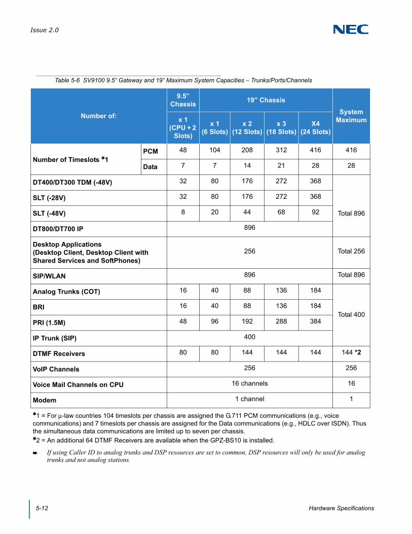
Issue 2.0
5-12 Hardware Specifications
Table 5-6 SV9100 9.5” Gateway and 19” Maximum System Capacities – Trunks/Ports/Channels
Number of:
9.5” Chassis
19” Chassis
System Maximumx 1
(CPU + 2 Slots)
x 1(6 Slots)
x 2(12 Slots)
x 3(18 Slots)
X4(24 Slots)
Number of Timeslots 1PCM 48 104 208 312 416 416
Data 7 7 14 21 28 28
DT400/DT300 TDM (-48V) 32 80 176 272 368
Total 896
SLT (-28V) 32 80 176 272 368
SLT (-48V) 8 20 44 68 92
DT800/DT700 IP 896
Desktop Applications(Desktop Client, Desktop Client with Shared Services and SoftPhones)
256 Total 256
SIP/WLAN 896 Total 896
Analog Trunks (COT) 16 40 88 136 184
Total 400BRI 16 40 88 136 184
PRI (1.5M) 48 96 192 288 384
IP Trunk (SIP) 400
DTMF Receivers 80 80 144 144 144 144 *2
VoIP Channels 256 256
Voice Mail Channels on CPU 16 channels 16
Modem 1 channel 1
1 = For-law countries 104 timeslots per chassis are assigned the G.711 PCM communications (e.g., voice communications) and 7 timeslots per chassis are assigned for the Data communications (e.g., HDLC over ISDN). Thus the simultaneous data communications are limited up to seven per chassis.2 = An additional 64 DTMF Receivers are available when the GPZ-BS10 is installed.
If using Caller ID to analog trunks and DSP resources are set to common, DSP resources will only be used for analog trunks and not analog stations.
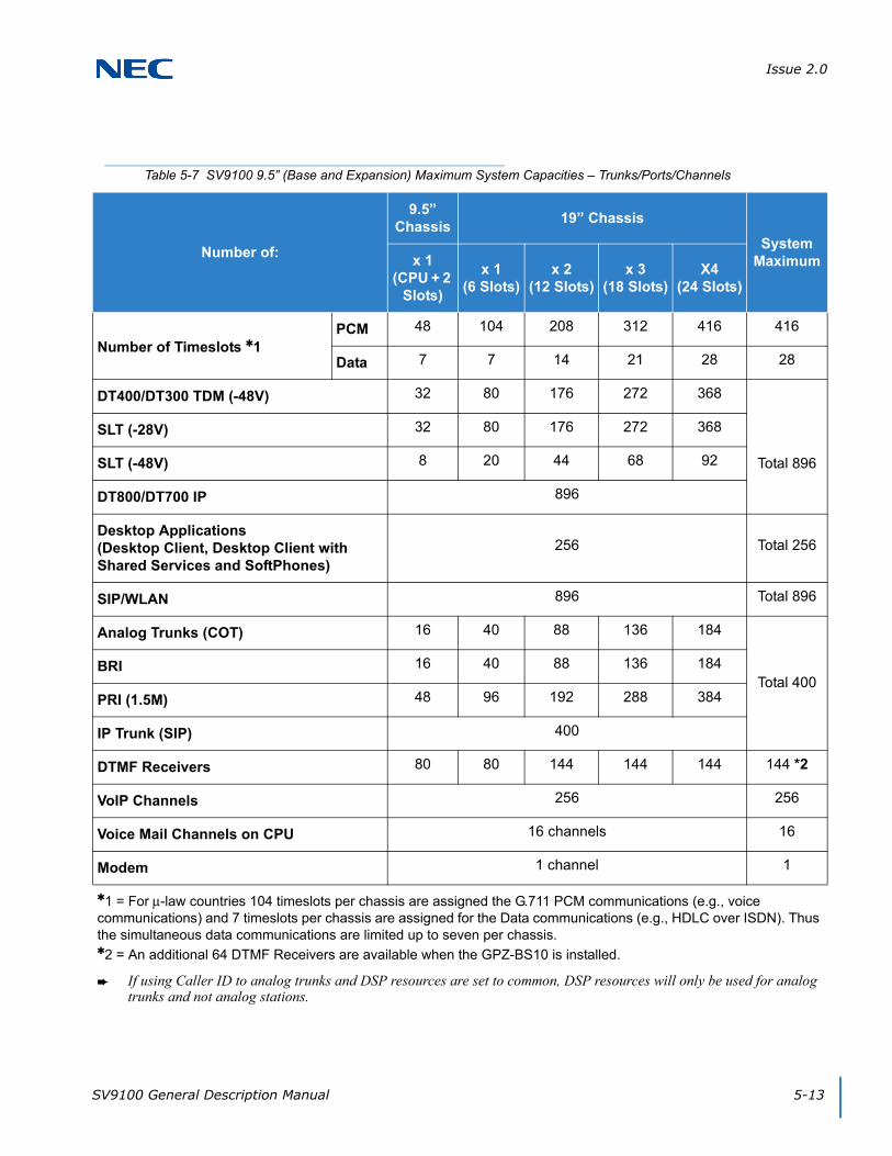
Issue 2.0
SV9100 General Description Manual 5-13
Table 5-7 SV9100 9.5” (Base and Expansion) Maximum System Capacities – Trunks/Ports/Channels
Number of:
9.5” Chassis
19” Chassis
System Maximumx 1
(CPU + 2 Slots)
x 1(6 Slots)
x 2(12 Slots)
x 3(18 Slots)
X4(24 Slots)
Number of Timeslots 1PCM 48 104 208 312 416 416
Data 7 7 14 21 28 28
DT400/DT300 TDM (-48V) 32 80 176 272 368
Total 896
SLT (-28V) 32 80 176 272 368
SLT (-48V) 8 20 44 68 92
DT800/DT700 IP 896
Desktop Applications(Desktop Client, Desktop Client with Shared Services and SoftPhones)
256 Total 256
SIP/WLAN 896 Total 896
Analog Trunks (COT) 16 40 88 136 184
Total 400BRI 16 40 88 136 184
PRI (1.5M) 48 96 192 288 384
IP Trunk (SIP) 400
DTMF Receivers 80 80 144 144 144 144 *2
VoIP Channels 256 256
Voice Mail Channels on CPU 16 channels 16
Modem 1 channel 1
1 = For-law countries 104 timeslots per chassis are assigned the G.711 PCM communications (e.g., voice communications) and 7 timeslots per chassis are assigned for the Data communications (e.g., HDLC over ISDN). Thus the simultaneous data communications are limited up to seven per chassis.2 = An additional 64 DTMF Receivers are available when the GPZ-BS10 is installed.
If using Caller ID to analog trunks and DSP resources are set to common, DSP resources will only be used for analog trunks and not analog stations.
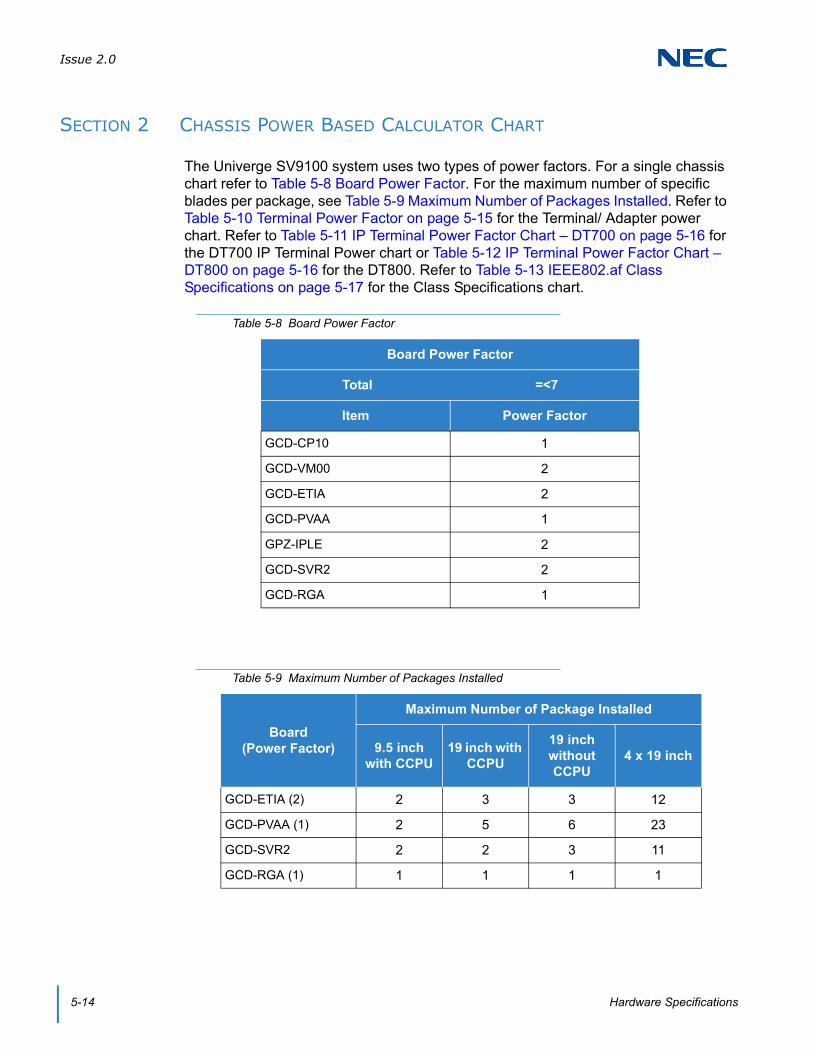
Issue 2.0
5-14 Hardware Specifications
SECTION 2 CHASSIS POWER BASED CALCULATOR CHART
The Univerge SV9100 system uses two types of power factors. For a single chassis chart refer to Table 5-8 Board Power Factor. For the maximum number of specific blades per package, see Table 5-9 Maximum Number of Packages Installed. Refer to Table 5-10 Terminal Power Factor on page 5-15 for the Terminal/ Adapter power chart. Refer to Table 5-11 IP Terminal Power Factor Chart – DT700 on page 5-16 for the DT700 IP Terminal Power chart or Table 5-12 IP Terminal Power Factor Chart – DT800 on page 5-16 for the DT800. Refer to Table 5-13 IEEE802.af Class Specifications on page 5-17 for the Class Specifications chart.
Table 5-8 Board Power Factor
Board Power Factor
Total =<7
Item Power Factor
GCD-CP10 1
GCD-VM00 2
GCD-ETIA 2
GCD-PVAA 1
GPZ-IPLE 2
GCD-SVR2 2
GCD-RGA 1
Table 5-9 Maximum Number of Packages Installed
Board(Power Factor)
Maximum Number of Package Installed
9.5 inch with CCPU
19 inch with CCPU
19 inch without CCPU
4 x 19 inch
GCD-ETIA (2) 2 3 3 12
GCD-PVAA (1) 2 5 6 23
GCD-SVR2 2 2 3 11
GCD-RGA (1) 1 1 1 1
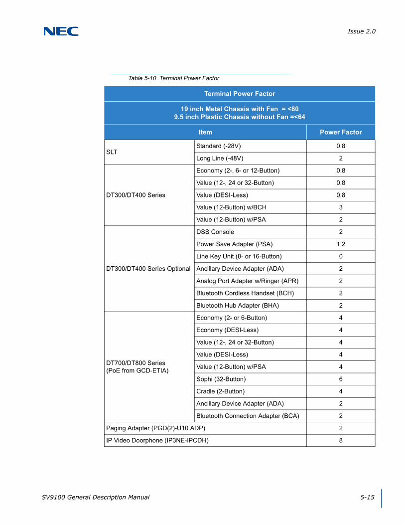
Issue 2.0
SV9100 General Description Manual 5-15
Table 5-10 Terminal Power Factor
Terminal Power Factor
19 inch Metal Chassis with Fan = <809.5 inch Plastic Chassis without Fan =<64
Item Power Factor
SLTStandard (-28V) 0.8
Long Line (-48V) 2
DT300/DT400 Series
Economy (2-, 6- or 12-Button) 0.8
Value (12-, 24 or 32-Button) 0.8
Value (DESI-Less) 0.8
Value (12-Button) w/BCH 3
Value (12-Button) w/PSA 2
DT300/DT400 Series Optional
DSS Console 2
Power Save Adapter (PSA) 1.2
Line Key Unit (8- or 16-Button) 0
Ancillary Device Adapter (ADA) 2
Analog Port Adapter w/Ringer (APR) 2
Bluetooth Cordless Handset (BCH) 2
Bluetooth Hub Adapter (BHA) 2
DT700/DT800 Series(PoE from GCD-ETIA)
Economy (2- or 6-Button) 4
Economy (DESI-Less) 4
Value (12-, 24 or 32-Button) 4
Value (DESI-Less) 4
Value (12-Button) w/PSA 4
Sophi (32-Button) 6
Cradle (2-Button) 4
Ancillary Device Adapter (ADA) 2
Bluetooth Connection Adapter (BCA) 2
Paging Adapter (PGD(2)-U10 ADP) 2
IP Video Doorphone (IP3NE-IPCDH) 8
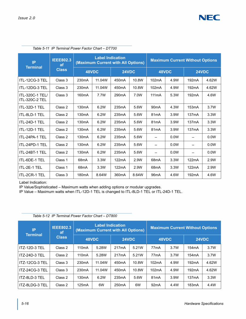
Issue 2.0
5-16 Hardware Specifications
Table 5-11 IP Terminal Power Factor Chart – DT700
IPTerminal
IEEE802.3af
Class
Label Indication(Maximum Current with All Options)
Maximum Current Without Options
48VDC 24VDC 48VDC 24VDC
ITL-12CG-3 TEL Class 3 230mA 11.04W 450mA 10.8W 102mA 4.9W 192mA 4.62W
ITL-12DG-3 TEL Class 3 230mA 11.04W 450mA 10.8W 102mA 4.9W 192mA 4.62W
ITL-320C-1 TEL/ITL-320C-2 TEL
Class 3 160mA 7.7W 290mA 7.0W 111mA 5.3W 192mA 4.6W
ITL-32D-1 TEL Class 2 130mA 6.2W 235mA 5.6W 90mA 4.3W 153mA 3.7W
ITL-8LD-1 TEL Class 2 130mA 6.2W 235mA 5.6W 81mA 3.9W 137mA 3.3W
ITL-24D-1 TEL Class 2 130mA 6.2W 235mA 5.6W 81mA 3.9W 137mA 3.3W
ITL-12D-1 TEL Class 2 130mA 6.2W 235mA 5.6W 81mA 3.9W 137mA 3.3W
ITL-24PA-1 TEL Class 2 130mA 6.2W 235mA 5.6W – 0.0W – 0.0W
ITL-24PD-1 TEL Class 2 130mA 6.2W 235mA 5.6W – 0.0W – 0.0W
ITL-24BT-1 TEL Class 2 130mA 6.2W 235mA 5.6W – 0.0W – 0.0W
ITL-6DE-1 TEL Class 1 68mA 3.3W 122mA 2.9W 68mA 3.3W 122mA 2.9W
ITL-2E-1 TEL Class 1 68mA 3.3W 122mA 2.9W 68mA 3.3W 122mA 2.9W
ITL-2CR-1 TEL Class 3 180mA 8.64W 360mA 8.64W 96mA 4.6W 192mA 4.6W
Label Indication:IP Value/Sophisticated – Maximum watts when adding options or modular upgrades.IP Value – Maximum watts when ITL-12D-1 TEL is changed to ITL-8LD-1 TEL or ITL-24D-1 TEL.
Table 5-12 IP Terminal Power Factor Chart – DT800
IPTerminal
IEEE802.3af
Class
Label Indication(Maximum Current with All Options)
Maximum Current Without Options
48VDC 24VDC 48VDC 24VDC
ITZ-12D-3 TEL Class 2 110mA 5.28W 217mA 5.21W 77mA 3.7W 154mA 3.7W
ITZ-24D-3 TEL Class 2 110mA 5.28W 217mA 5.21W 77mA 3.7W 154mA 3.7W
ITZ-12CG-3 TEL Class 3 230mA 11.04W 450mA 10.8W 102mA 4.9W 192mA 4.62W
ITZ-24CG-3 TEL Class 3 230mA 11.04W 450mA 10.8W 102mA 4.9W 192mA 4.62W
ITZ-8LD-3 TEL Class 2 130mA 6.2W 235mA 5.6W 81mA 3.9W 137mA 3.3W
ITZ-8LDG-3 TEL Class 2 125mA 6W 250mA 6W 92mA 4.4W 183mA 4.4W
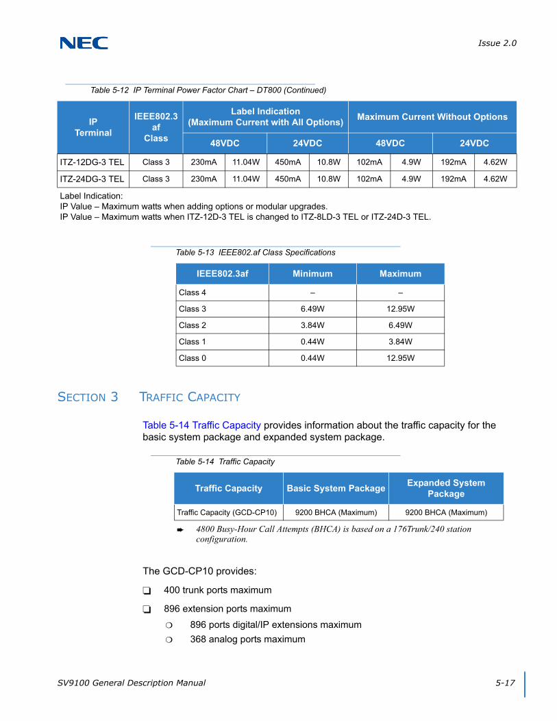
Issue 2.0
SV9100 General Description Manual 5-17
SECTION 3 TRAFFIC CAPACITY
Table 5-14 Traffic Capacity provides information about the traffic capacity for the basic system package and expanded system package.
The GCD-CP10 provides:
400 trunk ports maximum
896 extension ports maximum
896 ports digital/IP extensions maximum
368 analog ports maximum
ITZ-12DG-3 TEL Class 3 230mA 11.04W 450mA 10.8W 102mA 4.9W 192mA 4.62W
ITZ-24DG-3 TEL Class 3 230mA 11.04W 450mA 10.8W 102mA 4.9W 192mA 4.62W
Label Indication:IP Value – Maximum watts when adding options or modular upgrades.IP Value – Maximum watts when ITZ-12D-3 TEL is changed to ITZ-8LD-3 TEL or ITZ-24D-3 TEL.
Table 5-12 IP Terminal Power Factor Chart – DT800 (Continued)
IPTerminal
IEEE802.3af
Class
Label Indication(Maximum Current with All Options)
Maximum Current Without Options
48VDC 24VDC 48VDC 24VDC
Table 5-13 IEEE802.af Class Specifications
IEEE802.3af Minimum Maximum
Class 4 – –
Class 3 6.49W 12.95W
Class 2 3.84W 6.49W
Class 1 0.44W 3.84W
Class 0 0.44W 12.95W
Table 5-14 Traffic Capacity
Traffic Capacity Basic System PackageExpanded System
Package
Traffic Capacity (GCD-CP10) 9200 BHCA (Maximum) 9200 BHCA (Maximum)
4800 Busy-Hour Call Attempts (BHCA) is based on a 176Trunk/240 station configuration.
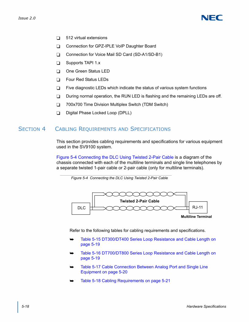
Issue 2.0
5-18 Hardware Specifications
512 virtual extensions
Connection for GPZ-IPLE VoIP Daughter Board
Connection for Voice Mail SD Card (SD-A1/SD-B1)
Supports TAPI 1.x
One Green Status LED
Four Red Status LEDs
Five diagnostic LEDs which indicate the status of various system functions
During normal operation, the RUN LED is flashing and the remaining LEDs are off.
700x700 Time Division Multiplex Switch (TDM Switch)
Digital Phase Locked Loop (DPLL)
SECTION 4 CABLING REQUIREMENTS AND SPECIFICATIONS
This section provides cabling requirements and specifications for various equipment used in the SV9100 system.
Figure 5-4 Connecting the DLC Using Twisted 2-Pair Cable is a diagram of the chassis connected with each of the multiline terminals and single line telephones by a separate twisted 1-pair cable or 2-pair cable (only for multiline terminals).
Refer to the following tables for cabling requirements and specifications.
Table 5-15 DT300/DT400 Series Loop Resistance and Cable Length on page 5-19
Table 5-16 DT700/DT800 Series Loop Resistance and Cable Length on page 5-19
Table 5-17 Cable Connection Between Analog Port and Single Line Equipment on page 5-20
Table 5-18 Cabling Requirements on page 5-21
Figure 5-4 Connecting the DLC Using Twisted 2-Pair Cable
Multiline Terminal
Twisted 2-Pair Cable
RJ-11DLC
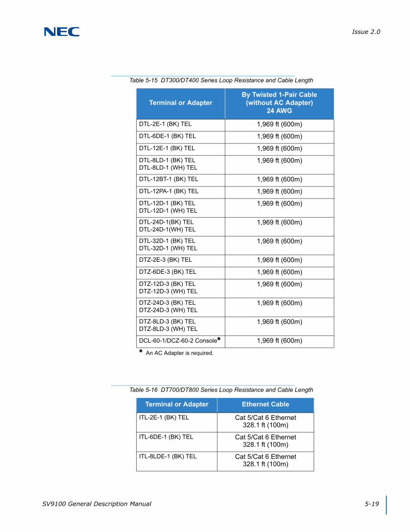
Issue 2.0
SV9100 General Description Manual 5-19
Table 5-15 DT300/DT400 Series Loop Resistance and Cable Length
Terminal or AdapterBy Twisted 1-Pair Cable
(without AC Adapter)24 AWG
DTL-2E-1 (BK) TEL 1,969 ft (600m)
DTL-6DE-1 (BK) TEL 1,969 ft (600m)
DTL-12E-1 (BK) TEL 1,969 ft (600m)
DTL-8LD-1 (BK) TELDTL-8LD-1 (WH) TEL
1,969 ft (600m)
DTL-12BT-1 (BK) TEL 1,969 ft (600m)
DTL-12PA-1 (BK) TEL 1,969 ft (600m)
DTL-12D-1 (BK) TELDTL-12D-1 (WH) TEL
1,969 ft (600m)
DTL-24D-1(BK) TELDTL-24D-1(WH) TEL
1,969 ft (600m)
DTL-32D-1 (BK) TELDTL-32D-1 (WH) TEL
1,969 ft (600m)
DTZ-2E-3 (BK) TEL 1,969 ft (600m)
DTZ-6DE-3 (BK) TEL 1,969 ft (600m)
DTZ-12D-3 (BK) TELDTZ-12D-3 (WH) TEL
1,969 ft (600m)
DTZ-24D-3 (BK) TELDTZ-24D-3 (WH) TEL
1,969 ft (600m)
DTZ-8LD-3 (BK) TELDTZ-8LD-3 (WH) TEL
1,969 ft (600m)
DCL-60-1/DCZ-60-2 Console 1,969 ft (600m)
An AC Adapter is required.
Table 5-16 DT700/DT800 Series Loop Resistance and Cable Length
Terminal or Adapter Ethernet Cable
ITL-2E-1 (BK) TEL Cat 5/Cat 6 Ethernet328.1 ft (100m)
ITL-6DE-1 (BK) TEL Cat 5/Cat 6 Ethernet328.1 ft (100m)
ITL-8LDE-1 (BK) TEL Cat 5/Cat 6 Ethernet328.1 ft (100m)
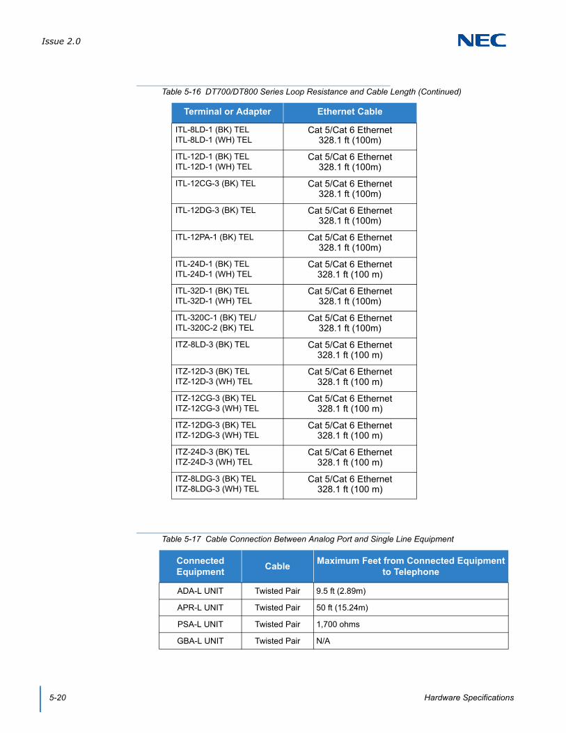
Issue 2.0
5-20 Hardware Specifications
ITL-8LD-1 (BK) TELITL-8LD-1 (WH) TEL
Cat 5/Cat 6 Ethernet328.1 ft (100m)
ITL-12D-1 (BK) TELITL-12D-1 (WH) TEL
Cat 5/Cat 6 Ethernet328.1 ft (100m)
ITL-12CG-3 (BK) TEL Cat 5/Cat 6 Ethernet328.1 ft (100m)
ITL-12DG-3 (BK) TEL Cat 5/Cat 6 Ethernet328.1 ft (100m)
ITL-12PA-1 (BK) TEL Cat 5/Cat 6 Ethernet328.1 ft (100m)
ITL-24D-1 (BK) TELITL-24D-1 (WH) TEL
Cat 5/Cat 6 Ethernet328.1 ft (100 m)
ITL-32D-1 (BK) TELITL-32D-1 (WH) TEL
Cat 5/Cat 6 Ethernet328.1 ft (100m)
ITL-320C-1 (BK) TEL/ITL-320C-2 (BK) TEL
Cat 5/Cat 6 Ethernet328.1 ft (100m)
ITZ-8LD-3 (BK) TEL Cat 5/Cat 6 Ethernet328.1 ft (100 m)
ITZ-12D-3 (BK) TELITZ-12D-3 (WH) TEL
Cat 5/Cat 6 Ethernet328.1 ft (100 m)
ITZ-12CG-3 (BK) TELITZ-12CG-3 (WH) TEL
Cat 5/Cat 6 Ethernet328.1 ft (100 m)
ITZ-12DG-3 (BK) TELITZ-12DG-3 (WH) TEL
Cat 5/Cat 6 Ethernet328.1 ft (100 m)
ITZ-24D-3 (BK) TELITZ-24D-3 (WH) TEL
Cat 5/Cat 6 Ethernet328.1 ft (100 m)
ITZ-8LDG-3 (BK) TELITZ-8LDG-3 (WH) TEL
Cat 5/Cat 6 Ethernet328.1 ft (100 m)
Table 5-17 Cable Connection Between Analog Port and Single Line Equipment
Connected Equipment
CableMaximum Feet from Connected Equipment
to Telephone
ADA-L UNIT Twisted Pair 9.5 ft (2.89m)
APR-L UNIT Twisted Pair 50 ft (15.24m)
PSA-L UNIT Twisted Pair 1,700 ohms
GBA-L UNIT Twisted Pair N/A
Table 5-16 DT700/DT800 Series Loop Resistance and Cable Length (Continued)
Terminal or Adapter Ethernet Cable
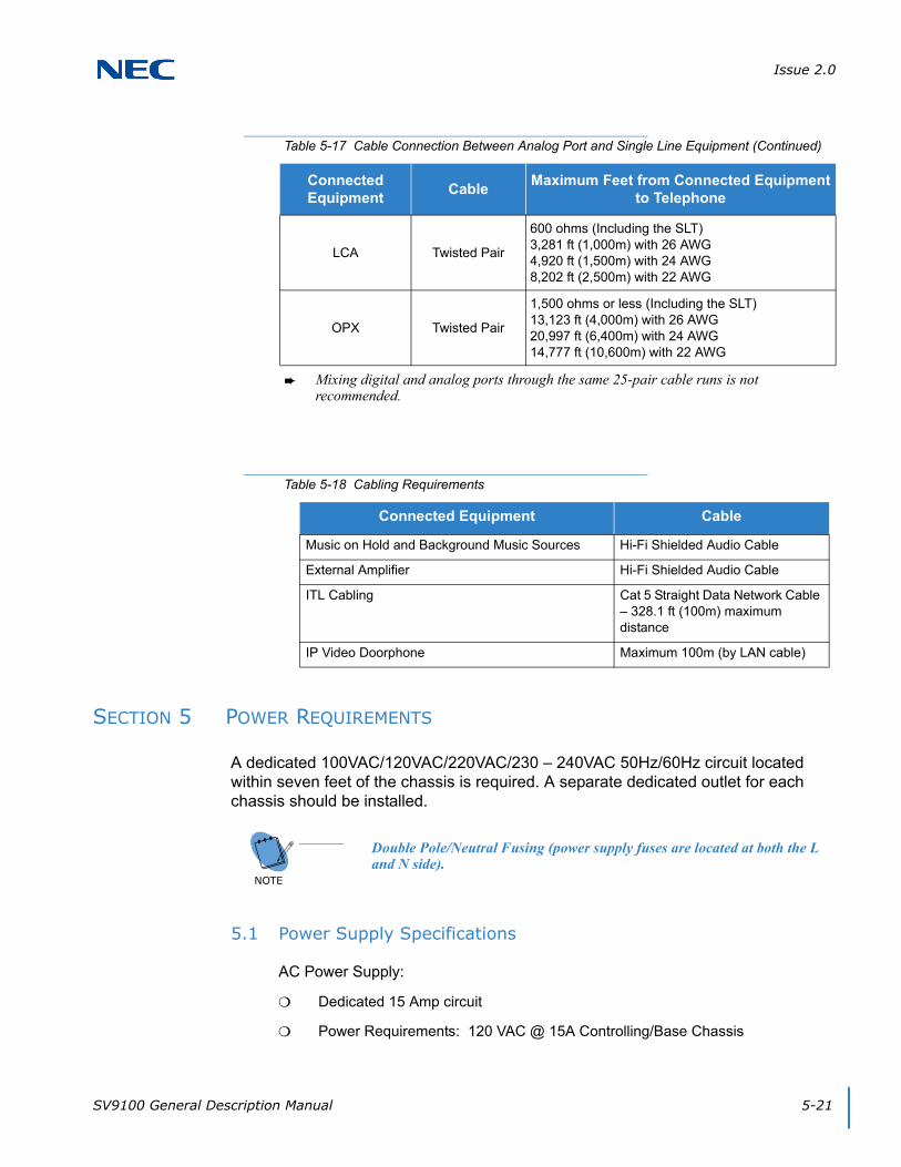
Issue 2.0
SV9100 General Description Manual 5-21
SECTION 5 POWER REQUIREMENTS
A dedicated 100VAC/120VAC/220VAC/230 – 240VAC 50Hz/60Hz circuit located within seven feet of the chassis is required. A separate dedicated outlet for each chassis should be installed.
5.1 Power Supply Specifications
AC Power Supply:
Dedicated 15 Amp circuit
Power Requirements: 120 VAC @ 15A Controlling/Base Chassis
LCA Twisted Pair
600 ohms (Including the SLT)3,281 ft (1,000m) with 26 AWG4,920 ft (1,500m) with 24 AWG8,202 ft (2,500m) with 22 AWG
OPX Twisted Pair
1,500 ohms or less (Including the SLT)13,123 ft (4,000m) with 26 AWG20,997 ft (6,400m) with 24 AWG14,777 ft (10,600m) with 22 AWG
Mixing digital and analog ports through the same 25-pair cable runs is not recommended.
Table 5-18 Cabling Requirements
Connected Equipment Cable
Music on Hold and Background Music Sources Hi-Fi Shielded Audio Cable
External Amplifier Hi-Fi Shielded Audio Cable
ITL Cabling Cat 5 Straight Data Network Cable – 328.1 ft (100m) maximum distance
IP Video Doorphone Maximum 100m (by LAN cable)
Table 5-17 Cable Connection Between Analog Port and Single Line Equipment (Continued)
Connected Equipment
CableMaximum Feet from Connected Equipment
to Telephone
NOTE
Double Pole/Neutral Fusing (power supply fuses are located at both the L and N side).
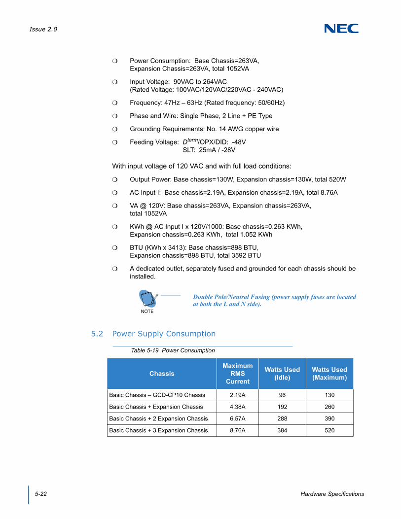
Issue 2.0
5-22 Hardware Specifications
Power Consumption: Base Chassis=263VA,Expansion Chassis=263VA, total 1052VA
Input Voltage: 90VAC to 264VAC (Rated Voltage: 100VAC/120VAC/220VAC - 240VAC)
Frequency: 47Hz – 63Hz (Rated frequency: 50/60Hz)
Phase and Wire: Single Phase, 2 Line + PE Type
Grounding Requirements: No. 14 AWG copper wire
Feeding Voltage: Dterm/OPX/DID: -48V SLT: 25mA / -28V
With input voltage of 120 VAC and with full load conditions:
Output Power: Base chassis=130W, Expansion chassis=130W, total 520W
AC Input I: Base chassis=2.19A, Expansion chassis=2.19A, total 8.76A
VA @ 120V: Base chassis=263VA, Expansion chassis=263VA,total 1052VA
KWh @ AC Input I x 120V/1000: Base chassis=0.263 KWh,Expansion chassis=0.263 KWh, total 1.052 KWh
BTU (KWh x 3413): Base chassis=898 BTU,Expansion chassis=898 BTU, total 3592 BTU
A dedicated outlet, separately fused and grounded for each chassis should be installed.
5.2 Power Supply Consumption
NOTE
Double Pole/Neutral Fusing (power supply fuses are located at both the L and N side).
Table 5-19 Power Consumption
ChassisMaximum
RMSCurrent
Watts Used (Idle)
Watts Used (Maximum)
Basic Chassis – GCD-CP10 Chassis 2.19A 96 130
Basic Chassis + Expansion Chassis 4.38A 192 260
Basic Chassis + 2 Expansion Chassis 6.57A 288 390
Basic Chassis + 3 Expansion Chassis 8.76A 384 520
Issue 2.0
SV9100 General Description Manual 5-23
SECTION 6 ENVIRONMENTAL CONDITIONS
6.1 Temperature and Humidity
Chassis, Telephones, BCH, BHA, 16LK, Console, ADA, APR
Operating Temperature: +32°F ~ +104°F (0°C ~ 40°C)
Recommended Long Term Temperature: -4°F ~ +140°F (-20°C ~ 60°C)
Operating Humidity: 10 ~ 90% RH (non-condensing)
Recommended Long Term Humidity: 10 ~ 90% RH
Blades – GPZ-BS10, GPZ-BS11, GCD-8DLCA with GPZ-8DLCB Daughter Board, GCD-16DLCA
Operating Temperature: +32°F ~ +104oF (0oC ~ 40oC)
Recommended Long Term Temperature: -4°F ~ +140°F (-20°C ~ 60°C)
Humidity: 10 ~ 90% RH (non-condensing)
Recommended Long Term Humidity: 10 ~ 90% RH
Blades – GCD-4LCA with GPZ-4LCA Daughter Board, GCD-8LCA with GPZ-8LCE Daughter Board, GCD-4COTB with GPZ-4COTF Daughter Board, GCD-PRTA
Operating Temperature: +32°F ~ +104°F (0°C ~ 40°C)
Recommended Long Term Temperature: -4°F ~ +140°F (-20°C ~ 60°C)
Operating Humidity: 10 ~ 90% RH (non-condensing)
Recommended Long Term Humidity: 20 ~ 90% RH
Door Box
Operating Temperature: -4°F ~ +104oF (-20oC ~ 60oC
Operating Humidity: 20 ~ 80% (non-condensing)
SV9100 Power Supply – MPS7101
Operating Temperature: +32°F ~ +104°F (0oC ~ +40oC)
Recommended Long Term Temperature: -4F ~ 167oF (-40oC ~ 75oC)
Operating Humidity: 20 ~ 95% RH (non-condensing)
Recommended Long Term Humidity: 10 ~ 95% RH
Issue 2.0
5-24 Hardware Specifications
Video Doorphone
Operating Temperature: +14°F ~ +113°F (-10oC ~ +45oC)
Storage Temperature: -4F ~ 140oF (-20oC ~ +60oC)
Operating Humidity: 90% or less (non-condensing)
Storage Humidity: 90% or less (non-condensing)
6.2 Outside Line Types
The following outside lines can be used with the UNIVERGE SV9100 system.
2-wire, Loop Start or Ground Start Trunks
2-wire, 2-way DID Lines (Dial Pulse or DTMF)
DID feature is not available for European and Australian markets.
4-wire, E&M Tie Lines (Type I or V, Dial Pulse, or DTMF)
Digital Trunk T1/FT1 (Loop Start, Ground Start, Tie Line (E&M), or DID Signaling)
ISDN-BRI Trunks
ISDN-PRI Trunks
VoIP Trunks (Internet Protocols)
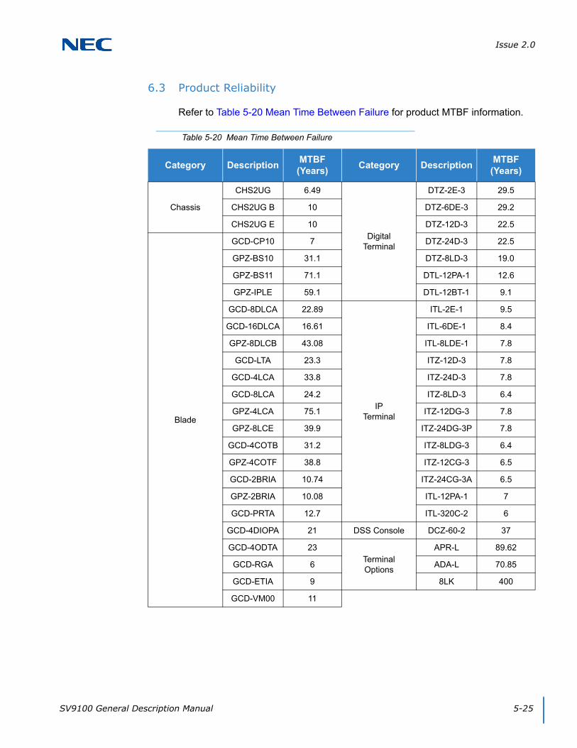
Issue 2.0
SV9100 General Description Manual 5-25
6.3 Product Reliability
Refer to Table 5-20 Mean Time Between Failure for product MTBF information.
Table 5-20 Mean Time Between Failure
Category DescriptionMTBF
(Years)Category Description
MTBF(Years)
Chassis
CHS2UG 6.49
DigitalTerminal
DTZ-2E-3 29.5
CHS2UG B 10 DTZ-6DE-3 29.2
CHS2UG E 10 DTZ-12D-3 22.5
Blade
GCD-CP10 7 DTZ-24D-3 22.5
GPZ-BS10 31.1 DTZ-8LD-3 19.0
GPZ-BS11 71.1 DTL-12PA-1 12.6
GPZ-IPLE 59.1 DTL-12BT-1 9.1
GCD-8DLCA 22.89
IPTerminal
ITL-2E-1 9.5
GCD-16DLCA 16.61 ITL-6DE-1 8.4
GPZ-8DLCB 43.08 ITL-8LDE-1 7.8
GCD-LTA 23.3 ITZ-12D-3 7.8
GCD-4LCA 33.8 ITZ-24D-3 7.8
GCD-8LCA 24.2 ITZ-8LD-3 6.4
GPZ-4LCA 75.1 ITZ-12DG-3 7.8
GPZ-8LCE 39.9 ITZ-24DG-3P 7.8
GCD-4COTB 31.2 ITZ-8LDG-3 6.4
GPZ-4COTF 38.8 ITZ-12CG-3 6.5
GCD-2BRIA 10.74 ITZ-24CG-3A 6.5
GPZ-2BRIA 10.08 ITL-12PA-1 7
GCD-PRTA 12.7 ITL-320C-2 6
GCD-4DIOPA 21 DSS Console DCZ-60-2 37
GCD-4ODTA 23TerminalOptions
APR-L 89.62
GCD-RGA 6 ADA-L 70.85
GCD-ETIA 9 8LK 400
GCD-VM00 11
Issue 2.0
5-26 Hardware Specifications
6.4 Transmission, Network, and Control Specifications
6.4.1 Transmission
Data Length:
From multiline terminal to GCD-8DLCA: 23 bits
From GCD-8DLCA to multiline terminal: 23 bits
Data Transmission Rates:
Between GCD-8DLCA and multiline terminal: 184K bps (voice and signaling)
Scanning Time for each multiline terminal: 32ms.
6.4.2 Network
Time Division Multiplexing (TDM) allows transmission of data and voice simultaneously over one communications medium. The specifications that the UNIVERGE SV9100 system uses for switching, clock, data bus, and timeframe are shown below.
TDM Switching: PCM (µ Law)
TDM Clock: 2.048 MHz
TDM Data Bus: 8-bit
TDM Timeframe: 125 µs.
6.4.3 Control
This section indicates the speed or capacity:
Control: Stored program with distributed processing
Central Processor: 32-bit microprocessor
Clock: P1015 processor 533 MHz
Interface Blade: 8- or 16-bit microprocessor
Optional Blades: 16- or 32-bit microprocessor
Multiline Terminal (TDM): 8-bit microprocessor
Multiline Terminal (IP): 32-bit microprocessor
IP Adapter: 32-bit microprocessor
Attendant Console: 4-bit microprocessor
SLT Adapter: 4-bit microprocessor
Issue 2.0
SV9100 General Description Manual 5-27
6.5 Dialing Specifications
6.5.1 Dial Pulse Address Signaling
Dial Pulse Address Signaling uses dial pulses (regular momentary interruptions) to signal the equipment. The following Dial Pulse specifications are used In the UNIVERGE SV9100 system.
Pulse Rate: 10 ± 0.5 pps/20 ± 1.0 pps
Percent Break: 60 ± 1.5%
Interdigit Interval: 0 pps/20 pps 770ms. ~ 830ms.
6.5.2 Dual-Tone Multifrequency (DTMF) Address Signaling
DTMF signaling includes push button or Touchtone dialing. When a key on a telephone is pushed, two tones (one high frequency and one low frequency) are provided. In the UNIVERGE SV9100 system, the following DTMF specifications are used.
Frequencies
Two sinusoidal frequencies are provided, one from the high frequency group and one from the low frequency group.
Frequency Deviation: Less than ±1.5%
Signal Level:
Nominal level per frequency: -6 ~ -4 dBm
Minimum level per frequency
Low Group: -10 dBm
High Group: -8 dBm
Maximum level per frequency: 0 dBm
Rise Time: Within 5ms.
Duration of Dual Frequency Signal:
110 ms. default/60ms. minimum
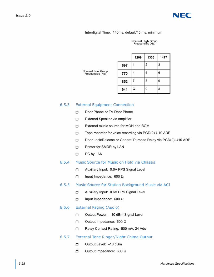
Issue 2.0
5-28 Hardware Specifications
Interdigital Time: 140ms. default/45 ms. minimum
6.5.3 External Equipment Connection
Door Phone or TV Door Phone
External Speaker via amplifier
External music source for MOH and BGM
Tape recorder for voice recording via PGD(2)-U10 ADP
Door Lock/Release or General Purpose Relay via PGD(2)-U10 ADP
Printer for SMDR by LAN
PC by LAN
6.5.4 Music Source for Music on Hold via Chassis
Auxiliary Input: 0.6V PPS Signal Level
Input Impedance: 600
6.5.5 Music Source for Station Background Music via ACI
Auxiliary Input: 0.6V PPS Signal Level
Input Impedance: 600
6.5.6 External Paging (Audio)
Output Power: –10 dBm Signal Level
Output Impedance: 600
Relay Contact Rating: 500 mA, 24 Vdc
6.5.7 External Tone Ringer/Night Chime Output
Output Level: –10 dBm
Output Impedance: 600
1209 1336 1477
697 1 2 3
770 4 5 6
852 7 8 9
941 Q 0 #
Nominal Low GroupFrequencies (Hz)
Nominal High GroupFrequencies (Hz)
Issue 2.0
SV9100 General Description Manual 5-29
Relay Contact Rating: 500 mA, 24 Vdc
6.5.8 SMDR Output
Female Connector (LAN)
6.5.9 PC Connection
Female Connector (LAN)
6.5.10 Relay Contact
All Relay Contact Ratings: 500 mA, 24Vdc
SECTION 7 BATTERY BACKUP
The UNIVERGE SV9100 system has battery backup functions for system backup and for memory backup.
7.1 System Backup (Optional)
During a power failure, the CHS2UG-US can be backed up using the CHS2U BATT MTG KIT for a backup time of 10 minutes or one of the CHS LARGE BATT SETs for a backup time ranging from 45~180 minutes. The CHS2UG GW-US can be backed up using the CHS2UG B SMALL BATT BOX for a backup time of 10 minutes.
7.2 Memory Backup
The GCD-CP10 blade battery retains the Clock/Calender and Last Number redial (LNR) buffers for each station when the GCD-CP10 blade encounters a power loss. With a fully charged battery, the settings are retained for about three years. The System Programmed memory (Customer Database) is stored in nonvolatile Memory and can be erased only by a First Initialization. After power is restored, the system blade returns to normal operation.
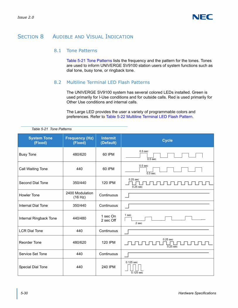
Issue 2.0
5-30 Hardware Specifications
SECTION 8 AUDIBLE AND VISUAL INDICATION
8.1 Tone Patterns
Table 5-21 Tone Patterns lists the frequency and the pattern for the tones. Tones are used to inform UNIVERGE SV9100 station users of system functions such as dial tone, busy tone, or ringback tone.
8.2 Multiline Terminal LED Flash Patterns
The UNIVERGE SV9100 system has several colored LEDs installed. Green is used primarily for I-Use conditions and for outside calls. Red is used primarily for Other Use conditions and internal calls.
The Large LED provides the user a variety of programmable colors and preferences. Refer to Table 5-22 Multiline Terminal LED Flash Pattern.
Table 5-21 Tone Patterns
System Tone(Fixed)
Frequency (Hz)(Fixed)
Intermit(Default)
Cycle
Busy Tone 480/620 60 IPM
Call Waiting Tone 440 60 IPM
Second Dial Tone 350/440 120 IPM
Howler Tone 2400 Modulation (16 Hz) Continuous
Internal Dial Tone 350/440 Continuous
Internal Ringback Tone 440/480 1 sec On2 sec Off
LCR Dial Tone 440 Continuous
Reorder Tone 480/620 120 IPM
Service Set Tone 440 Continuous
Special Dial Tone 440 240 IPM
0.5 sec
0.5 sec
0.5 sec
0.5 sec
0.25 sec
0.25 sec
1 sec
2 sec
0.25 sec
0.25 sec
0.125 sec
0.125 sec
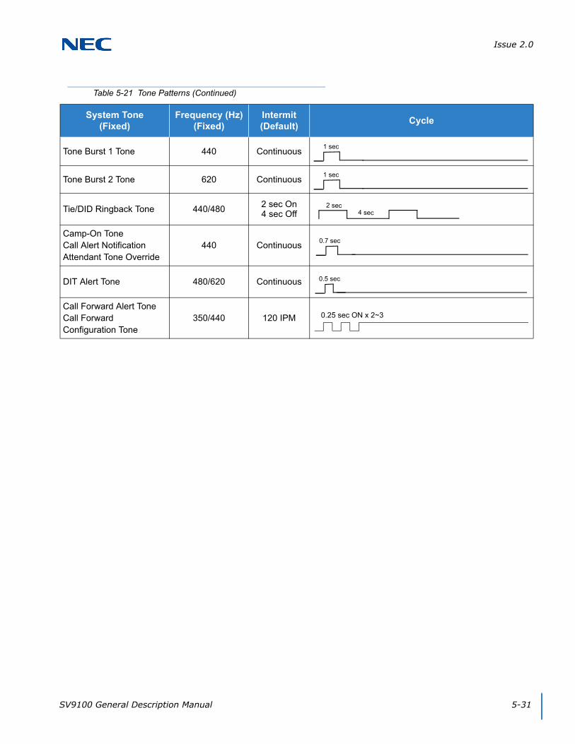
Issue 2.0
SV9100 General Description Manual 5-31
Tone Burst 1 Tone 440 Continuous
Tone Burst 2 Tone 620 Continuous
Tie/DID Ringback Tone 440/480 2 sec On4 sec Off
Camp-On ToneCall Alert NotificationAttendant Tone Override
440 Continuous
DIT Alert Tone 480/620 Continuous
Call Forward Alert ToneCall ForwardConfiguration Tone
350/440 120 IPM
Table 5-21 Tone Patterns (Continued)
System Tone(Fixed)
Frequency (Hz)(Fixed)
Intermit(Default)
Cycle
1 sec
1 sec
2 sec4 sec
0.7 sec
0.5 sec
0.25 sec ON x 2~3

Issue 2.0
5-32 Hardware Specifications
Table 5-22 Multiline Terminal LED Flash Pattern
LED Condition Color Flash Patterns
Line Key
I-UseBusyIncoming CallI-HoldCall HoldHold RecallTransfer RecallLive Monitoring ModeMessage Waiting on Line Key
GreenRedRedGreenRedGreenGreenGreenRed
Microphone ON Red
Mic ON (Series i) Red
Large LED 1
Incoming Internal CallIncoming Outside CallMessage from AttendantVoice Mail Message
RedGreenGreenRed
SpeakerONSystem Data Entry
RedRed
Answer
Incoming TrunkExclusive HoldUser Ringing Line PreferenceVoice Over with Broker’s Call
RedGreenRedGreen
Feature
Callback SetAuto Repeat SetON (to set function)Call FWD - All Calls Set
RedRedRedRed
BLF orDSS Key
Use, HoldDND, Call FWD-All Calls SetSpecial Mode (while pressing Feature or going off-line)
RedRedRed
1 = The Large LED provides the user a variety of programmable colors and preferences.
0 0.5 1.0 1.5 2.0 sec.

General Description Manual
NEC Corporation of AmericaIssue 2.0
SV9100®