Embed Size (px)
Citation preview

21
Technical data 8 5 ➔
Dimensions 9 5 ➔
Designation for UL 508A
Approvals 8 47–52
Universal busbar supportType Busbars Pack size Weight Part no.
kg/100 units
2-pole with internal screw holes 12, 20, 30 x 5, 10
3-pole with internal screw holes 12, 15, 20, 25, 30 x 5, 10
3-pole with additional external screw holes 12, 15, 20, 25, 30 x 5, 10
4-pole with internal screw holes 12, 15, 20, 25, 30 x 5, 10
UL busbar support3-pole with internal screw holes 12, 20, 30 x 5, 10
18 mm spacer, suitable for 01 508
4-pole with internal screw holes 12, 20, 30 x 5, 10
spacer, suitable for 01 357
Base plate, for UL busbar support 01 508, 01 231, 01 232
240 x 1100
240 x 700
PE/N busbar supports, including PE and N labels
2-pole individually mountable 12, 15, 20, 25, 30 x 5, 10
1-pole individually mountable 12, 20, 30 x 5,10
Connection busbar support2-pole with integrated 1.5 – 16mm2 terminals 12, 15, 20, 25, 30 x 5, 10
End cover, for covering busbar ends
Type Pack size Weight Part no.
kg/100 units
for 01 602
for 01 495, 01 500, 01 508 and 01 484
for 01 357 and 01 485, set right and left
1 8.3 01 602 06
10 12.7 01 495 06
10 13.7 01 500 06
10 26.6 01 485 06
10 14.0 01 508 06
10 9.1 01 358 06
10 19.7 01 357 06
10 13.1 01 359 06
01 359
XX XXX
2 73.7 01 518 06
2 46.9 01 515 06
10 9.5 01 356 06
1 5.9 01 601 06
10 27.9 01 484 06
1 1.5 01 363 06
10 2.0 01 573 06
5 5.6 01 131 06
01 622
01 485
01 619
01 131
01 356
01 601
01 500
01 508
01 495
01 573
** UL-certified products arehighlighted in grey
**
www.klinkmann.com

22
Standard copper busbars, tin-plated
Dimensions Length Cross section Pack size Weight Part no.
mm kg/100 units
12 x 5 2.4 m 60
790 mm 60
590 mm 60
15 x 5 2.4 m 75
20 x 5 2.4 m 100
790 mm 100
590 mm 100
25 x 5 2.4 m 125
30 x 5 2.4 m 150
790 mm 150
590 mm 150
12 x 10 2.4 m 120
790 mm 120
590 mm 120
20 x 10 3.6 m 200
2.4 m 200
790 mm 200
590 mm 200
30 x 10 3.6 m 300
2.4 m 300
790 mm 300
590 mm 300
1 128.2 01 618 06
1 42.7 01 381 06
1 32.1 01 382 06
1 160.2 01 619 06
1 213.6 01 620 06
1 71.2 01 383 06
1 53.4 01 384 06
1 267.0 01 621 06
1 320.4 01 622 06
1 106.8 01 387 06
1 80.1 01 388 06
1 256.3 01 623 06
1 85.4 01 389 06
1 64.1 01 390 06
1 650.0 01 140 06
1 427.2 01 624 06
1 142.4 01 391 06
1 106.8 01 392 06
1 961.0 01 204 06
1 640.8 01 625 06
1 213.6 01 393 06
1 160.2 01 394 06
01 382
01 390
01 383
01 387
01 625
**
Technical data 8 6 ➔
Designation for UL 508A
Approvals 8 47–52
New
60mm-system classic630A (800A) / 2500A
** UL-certified products arehighlighted in grey

23
Technical data 8 5 ➔
Dimensions 9 6 ➔
Designation for UL 508A
Approvals 8 47–52
New
Busbar support, for double-T profiles without end cover
Type Pack size Weight Part no.
kg/100 units
1-pole, individually mountable only
1-pole, for connection to 01 231 and individually mountable
3-pole
Busbar support, for triple-T-profiles without end cover
Type Pack size Weight Part no.
kg/100 units
1-pole, for connection to 01 232 and individually mountable
3-pole
End coverfor 01 116 and 01 132
for 01 231 and 01 232
10 15.8 01 876 06
4 13.0 01 116 06
3 59.1 01 231 06
4 15.0 01 132 06
2 69.7 01 232 06
4 1.8 01 373 06
4 4.8 01 234 06
01 227
01 232
01 231
01 132
01 116
01 876
01 234
** UL-certified products arehighlighted in grey
**

24
Technical data 8 7 ➔
Dimensions 9 22 ➔
Designation for UL 508A
Approvals 8 47–52
New
01 396
01 398
01 397
01 399
01 610
Standard copper busbar, tin-plated section profiles
Type Length Cross section Pack size Weight Part no.
mm2 kg/100 units
double-T section busbar 3.6 m 500
2.4 m 500
790 mm 500
653 mm 500
590 mm 500
453 mm 500
double-T section busbar 3.6 m 720
2.4 m 720
790 mm 720
653 mm 720
590 mm 720
453 mm 720
triple-T section busbar 3.6 m 1140
2.4 m 1140
790 mm 1140
653 mm 1140
590 mm 1140
453 mm 1140
TCC section busbar 2.4m 1600
692mm 1600
492mm 1600
Standard copper busbar, plain section profiles
Type Length Cross section Pack size Weight Part no.
mm2 kg/100 units
double-T section busbar 3.6m 500
2.4m 500
double-T section busbar 3.6m 720
2.4m 720
1 1566.0 01 224 06
1 1044.0 01 609 06
1 348.0 01 395 06
1 288.1 01 226 06
1 261.0 01 396 06
1 198.8 01 225 06
1 3210.0 01 190 06
1 1540.0 01 608 06
1 513.0 01 397 06
1 419.0 01 831 06
1 385.0 01 398 06
1 291.0 01 838 06
1 3654.0 01 227 06
1 2436.0 01 187 06
1 812.0 01 399 06
1 672.3 01 189 06
1 609.0 01 400 06
1 464.0 01 188 06
1 3400.0 01 610 06
1 980.0 01 378 06
1 700.0 01 377 06
1 1566.0 01 223 06
1 1044.0 01 250 06
1 3210.0 01 229 06
1 1540.0 01 249 06
60mm-system classic630A (800A) / 2500A
** UL-certified products arehighlighted in grey
**

25
Technical data 8 3 ➔
Dimensions 9 6,7,8 ➔
Designation for UL 508A
Approvals 8 47–52
Busbar coverType Pack size Weight Part no.
kg/100 units
for 12 – 30 x 5, 1m long
for 12 – 30 x 10, 1m long
for double-T and triple-T section, 1m long
for 12 x 5, 1m long
independent of the system, for individual busbars
Reserve section cover, 3-pole
cover section, 0.7m long, can only be used with mount no. 01 026 or 01 320
mount, 32mm depth, for cover section no. 01 025
mount, 107mm depth, for cover section no. 01 025can be combined with with 01 237, 01 238
can be used for systems with 12 x 5, – 30 x 10 busbars, double-T and triple-T section
System cover, 3-pole
holder set (left + right) for cover sections, 3-pole
front cover section (3-pole), 1.1m long, can only be used with holder no. 01 136
top/bottom cover section, 1.1m long, can only be used with holder no. 01 136 or 01 037
can be used for systems with 12, 20, 25, 30 x 5, 10 busbars, double-T and triple-T section
System cover, 4-pole
holder set (left + right) for cover sections, 4-pole
front cover section (4-pole), 1.1m long, can only be used with holder no. 01 137
top/bottom cover section, 1.1m long, can only be used with holder no. 01 136 or 01 137
can be used for systems with 12, 20, 25, 30 x 5, 10 busbars, double-T and triple-T section
Compartment section, for adjusting the installation depth in double-T and triple-T busbar systems
48mm deep, 2.4m long
76mm deep, 2.4m long
106mm deep, 2.4m long
10 8.7 01 244 06
10 10.1 01 245 06
5 38.0 01 252 06
10 3.2 78 463 06
2 47.8 01 025 06
10 3.9 01 026 06
8 12.0 01 320 06
1 18.0 01 136 07
1 45.1 01 554 07
2 27.1 01 555 07
1 21.0 01 137 07
1 58.0 01 599 07
2 27.1 01 555 07
1 70.0 01 236 06
1 105.0 01 237 06
1 140.0 01 238 06
** UL-certified products arehighlighted in grey
**01 555
01 554
01 136
01 025
01 237
01 026
01 252

26
60mm-system classic630A (800A) / 2500A
Technical data 8 9 ➔
Dimensions 9 8,9 ➔
Designation for UL 508A
Approvals 8 47–52
CRITO®ProfiLiner, connection module, 3-pole, for 12 x 5 – 30 x 10mm, shock-protected with spring terminals
Connection Dimensions For use Pack size Weight Part no.
W x H up to max. kg/100 units
1.5 – 16mm2 20 x 200 80A
Connecting terminal plate, 3-pole, for 12 x 5 - 30 x 10 and double-T and triple-T section, with cover cap
6 – 50mm2, s(r), f, f +AE; fl. Cu 6 x 9 x 0.8 54 x 200 300A
35 – 120mm2, s(r), f, f +AE; fl. Cu 6 /10 x 15.5 x 0.8 81 x 200 440A
AccessoriesType Pack size Weight Part no.
kg/100 units
additional individual cover for the terminals in 01 240
additional individual cover for the terminals in 01 243
Connecting terminal plate, for 20 x 5 – 30 x 10 and double-T and triple-T section, 3-pole, with cover cap
Connection Dimensions For use Pack size Weight Part no.
W x H up to max. kg/100 units
Cu and Al* 95 – 185mm2, s(r), s(s), f 135 x 200 460A
Cu and Al* 120 – 300mm2, s(r), s(s), f 135 x 200 560A
for fl. Cu up to 32 x 20** 135 x 200 800A
* not maintenance-free when aluminium conductors are used (see page 8/2)** observe minimum terminal space (see page 8/9)
Connection set, 3-pole, for 20 x 5 – 30 x 10mm and double-T and triple-T section, without cover cap
Cu and Al* 120 – 300mm2, s(r), s(s), f 153 x 184 560A
flat busbars up to 32 x 20mm 153 x 184 800A
* not maintenance-free when aluminium conductors are used (see page 8/2)
Connection set, 4-pole, for 20 x 5 – 30 x 10mm and double-T and triple-T section, without cover cap
Cu and Al* 120 – 300mm2, s(r), s(s), f 204 x 224 560A
flat busbars up to 32 x 20mm 204 x 224 800A
* not maintenance-free when aluminium conductors are used (see page 8/2)
8 18.1 01 563 07
1 45.1 01 240 07
1 53.5 01 243 07
3 0.4 01 300 07
3 0.5 01 301 07
1 132.2 01 199 07
1 165.7 01 754 07
1 144.7 01 753 07
1 155.5 01 537 07
1 132.5 01 538 07
1 210.0 01 147 07
1 180.0 01 162 07
** UL-certified products arehighlighted in grey
**01 537
01 754
01 243
01 240
01 563

27
Technical data 8 8,11 ➔
Dimensions 9 7,8,9,10 ➔
Designation for UL 508A
Approvals 8 47–52
Universal conductor terminalFor busbars Connection Terminal space For use Pack size Weight Part no.
mm2 min. – max. W x H up to max. kg/100 units
5mm flat busbars 1.5 – 16 7.5 x 7.5 180A
4 – 35 10.5 x 11 270A
16 – 70 14 x 14 400A
16 – 120 17 x 15 440A
10mm flat busbars 1.5 – 16 7.5 x 7.5 180A
4 – 35 10.5 x 11 270A
10mm, double-T 16 – 70 14 x 14 400Aand triple-T section 16 – 120 17 x 15 440A
CRITO®ProfiClip, brace terminals
For busbars Connection For use Pack size Weight Part no.
up to max. kg/100 units
20 x 5 – 30 x 10, for flat busbars up to 30 x 20 750Adouble-T and Cu and Al* 95 – 185mm2, s(r), s(s), f 500Atriple-T section for flat busbars up to 32 x 20 800A
Cu and Al* 120 – 300mm2, s(r), s(s), f 600A
* not maintenance-free when aluminium conductors are used (see page 8/2)
CRITO®PowerClip, brace terminal for the connection of flat and flexible copper busbars
For busbars Terminal space Applicable Pack size Weight Part no.
W x H up to max. kg/100 units
30 x 10, 55 x 28 1600A/2000A*double-T and 68 x 28 1600A/2000A*triple-T profile 105 x 28 1600A/2800A*
* in case of centre feed
Cover cap, 3-pole, can also be used as reserve section cover
Type For busbars Pack size Weight Part no.
W x H x D kg/100 units
54 x 200 x 55 12 x 5 – 30 x 10, double-T and triple-T section
84 x 200 x 55 12 x 5 – 30 x 10, double-T and triple-T section
135 x 200 x 90 20 x 5 – 30 x 10, double-T and triple-T section
180 x 200 x 90 12 x 5 – 30 x 10, double-T and triple-T section
228 x 200 x 90 12 x 5 – 30 x 10, double-T and triple-T section
250 x 200 x 90 12 x 5 – 30 x 10, double-T and triple-T section
270 x 200 x 90 20 x 5 – 30 x 10, double-T and triple-T section
Cover cap, 4-pole, can also be used as reserve section cover
228 x 260 x 90 12 x 5 – 30 x 10, double-T and triple-T section
100 2.1 01 284 07
50 4.6 01 285 07
25 7.1 01 287 07
25 10.6 01 068 07
100 2.3 01 289 07
50 4.7 01 290 07
25 7.5 01 292 07
25 10.9 01 203 07
6 30.3 01 319 07
6 31.2 01 318 07
3 34.7 01 759 07
3 42.5 01 760 07
3 50.0 01 069 07
3 63.0 01 070 07
3 84.0 01 071 07
1 14.7 01 590 07
10 14.9 01 413 07
1 29.5 01 756 07
1 33.0 01 539 07
1 37.3 01 596 07
1 39.3 01 540 07
1 64.7 01 757 07
1 45.0 01 597 07
old page 2/6
** UL-certified products arehighlighted in grey
**01 071
01 070
01 069
01 759
01 318
01 292
01 290
01 289

28
60mm-system classic630A (800A) / 2500A
Screw-type terminal, clip-on, for cable lug DIN 46 234
Type For use Pack size Weight Part no.
up to max. kg/100 units
undrilled flat busbars, M 5 x 8 360A5mm thick M 8 x 8 490A
M 10 x 10 630A
undrilled flat busbars, 10mm thick M 5 x 8 360A
undrilled flat busbars, 10mm thick and M 8 x 8 490Adouble-T and triple-T section M 10 x 10 630A
Busbar connector, to connect flat busbars and flexible Cu
Terminal space Terminal space Pack size Weight Part no.
W x L max. height kg/100 units
25 x 20 20
30 x 20 20
30 x 30 20
35 x 30 20
40 x 20 20
40 x 32 30
Busbar connection, along busbar length with wedge clamp terminal
Busbars Connection Terminal space Pack size Weight Part no.
mm2 min. – max. W x H kg/100 units
15 x 5 70 – 150 18 x 4 – 18
20 x 5 – 10 120 – 240 21 x 4 – 20
25 x 5 150 – 300 25 x 5 – 20
01 202
01 996
01 749
01 748
01 747
Technical data 8 10 ➔
Dimensions 9 10,23 ➔
Approvals 8 47–52
25 4.8 01 747 07
20 16.0 01 748 07
6 35.8 01 749 07
25 5.0 01 512 07
20 16.5 01 514 07
6 36.2 01 047 07
10 14.9 01 996 07
10 16.2 01 997 07
10 19.8 01 586 07
10 21.5 01 587 07
10 17.8 01 206 07
6 27.6 01 616 07
3 5.9 01 200 07
3 11.0 01 201 07
3 13.4 01 202 07
old page 2/7
29
Technical data 8 11 ➔
Dimensions 9 9,23 ➔
Designation for UL 508A
Approvals 8 47–52
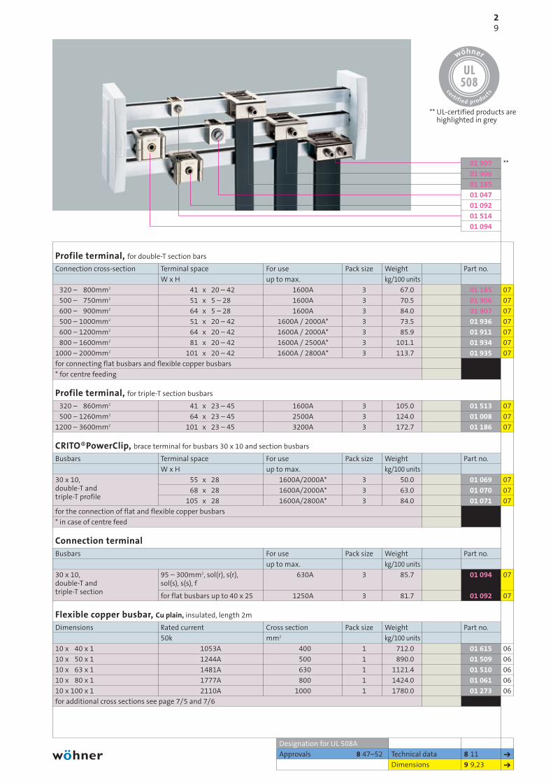
Profile terminal, for double-T section bars
Connection cross-section Terminal space For use Pack size Weight Part no.
W x H up to max. kg/100 units
320 – 800mm2 41 x 20 – 42 1600A
500 – 750mm2 51 x 5 – 28 1600A
600 – 900mm2 64 x 5 – 28 1600A
500 – 1000mm2 51 x 20 – 42 1600A / 2000A*
600 – 1200mm2 64 x 20 – 42 1600A / 2000A*
800 – 1600mm2 81 x 20 – 42 1600A / 2500A*
1000 – 2000mm2 101 x 20 – 42 1600A / 2800A*
for connecting flat busbars and flexible copper busbars
* for centre feeding
Profile terminal, for triple-T section busbars
320 – 860mm2 41 x 23 – 45 1600A
500 – 1260mm2 64 x 23 – 45 2500A
1200 – 3600mm2 101 x 23 – 45 3200A
CRITO®PowerClip, brace terminal for busbars 30 x 10 and section busbars
Busbars Terminal space For use Pack size Weight Part no.
W x H up to max. kg/100 units
30 x 10, 55 x 28 1600A/2000A*double-T and 68 x 28 1600A/2000A*triple-T profile 105 x 28 1600A/2800A*
for the connection of flat and flexible copper busbars
* in case of centre feed
Connection terminalBusbars For use Pack size Weight Part no.
up to max. kg/100 units
30 x 10, 95 – 300mm2, sol(r), s(r), 630Adouble-T and sol(s), s(s), ftriple-T section for flat busbars up to 40 x 25 1250A
Flexible copper busbar, Cu plain, insulated, length 2m
Dimensions Rated current Cross section Pack size Weight Part no.
50k mm2 kg/100 units
10 x 40 x 1 1053A 400
10 x 50 x 1 1244A 500
10 x 63 x 1 1481A 630
10 x 80 x 1 1777A 800
10 x 100 x 1 2110A 1000
for additional cross sections see page 7/5 and 7/6
3 67.0 01 185 07
3 70.5 01 906 07
3 84.0 01 907 07
3 73.5 01 936 07
3 85.9 01 911 07
3 101.1 01 934 07
3 113.7 01 935 07
3 105.0 01 513 07
3 124.0 01 008 07
3 172.7 01 186 07
3 50.0 01 069 07
3 63.0 01 070 07
3 84.0 01 071 07
3 85.7 01 094 07
3 81.7 01 092 07
1 712.0 01 615 06
1 890.0 01 509 06
1 1121.4 01 510 06
1 1424.0 01 061 06
1 1780.0 01 273 06
01 907
01 906
01 185
01 047
01 092
01 514
01 094
** UL-certified products arehighlighted in grey
**

60mm-system classic630A (800A) / 2500A
210
** UL-certified products arehighlighted in grey
**
old page 2/9
Busbar connector, for same-size busbars
Busbars Length System spacing For use Pack size Weight Part no.
up to max. kg/100 units
12 – 20 x 5 / 10 55 5 – 10 630A
150 100 – 110 630A
20 – 30 x 5 / 10 40 9 – 20 630A
40 13 – 20 630A
95 50 – 60 630A
150 100 – 110 630A
double-T section 50 9 – 20 1600A
95 50 – 60 1600A
150 100 – 110 1600A
70 5 – 10 1600A
triple-T section 95 50 – 60 2500A
150 100 – 110 2500A
3 units required for a 3-pole connection, use 01 026 or 01 320 and 01 025 as a cover (see page 2/5)
Connection set, 3-pole, for double-T or triple-T section busbars
Type For use Pack size Weight Part no.
up to max. kg/100 units
for a flexible connection double-T section 1600A
for a flexible corner coupling double-T section 1600A
for a flexible connection triple-T section 2500A
one set is required for a 3-pole connection
Phase separators for UL installation of end-to-end busbar connections, 3-pole
Type Width Pack size Weight Part no.
mm kg/100 units
for parts 01 166, 01 990, 01 823, 01 827* 105
for parts 01 141, 01 145, 01 274* 145
for parts 01 193, 01 886, 01 829, 01 275 200
* each depth dimension has to be cut to size
Technical data 8 10 ➔
Dimensions 9 11 ➔
Designation for UL 508A
Approvals 8 47–52
12 19.2 01 166 07
3 52.4 01 193 07
6 23.3 01 990 07
6 25.2 01 823 07
3 54.4 01 141 07
3 86.6 01 886 07
6 49.4 01 827 07
3 94.3 01 145 07
3 146.1 01 829 07
3 113.9 01 905 07
3 120.6 01 274 07
3 178.0 01 275 07
1 536.0 30 322 07
1 638.0 30 473 07
1 940.0 01 295 07
1 17.2 01 360 06
1 19.6 01 361 06
1 21.8 01 362 06
01 827
01 145
01 829
01 905
01 361
30 322

211
Technical data 8 12 ➔
Dimensions 9 12 ➔
Designation for UL 508A
Approvals 8 47–52
EQUES®MotorController
EQUES®MotorController 25A, busbar adapter, separable, with AWG 12 =̂ 4 mm2 wires
Type Adapter Adapter Pack size Weigth Part no.
width length kg/100 units
16A, 2 mounting rails, conductors 2,5mm2, 125 long 45 200
2 mounting rails 45 200
2 mounting rails 45 260
EQUES®MotorController 32A, busbar adapter, separable, with AWG 10 =̂ 6 mm2 wires
2 mounting rails 54 200
2 mounting rails 54 260
EQUES®MotorController 45A, busbar adapter, separable, with AWG 8 =̂ 10mm2 wires
2 mounting rails 54 200
2 mounting rails 54 260
EQUES®MotorController empty, busbar adapter, separable, without electrical contact
2 mounting rails 45 200
2 mounting rails 54 200
2 mounting rails 45 260
2 mounting rails 54 260
side-mounted module, connectable on both sides 9 200
Microswitch, to interrupt the coil current
1 break contact, 250 V, 5A for EQUES Motor Controller
All adapters for busbars 12, 15, 20, 25, 30mm x 5, 10mm, double-T and triple-T section
Accessories EQUES®Technologymounting rail 45
mounting rail 54
mounting rail 63
mounting rail 72
mounting rail 81
mounting rail end stop
connecting element
connector with support 8-pole, 2,5mm2, 250 V 45
connector with support 10-pole, 2,5mm2, 250 V 54
4 42.7 32 401 05
4 42.7 32 400 05
4 45.0 32 402 05
4 49.2 32 404 05
4 54.4 32 408 05
4 52.9 32 412 05
4 56.7 32 416 05
4 34.9 32 420 05
4 38.8 32 421 05
4 36.2 32 425 05
4 42.1 32 426 05
10 4.3 32 964 05
10 0.9 32 956 05
10 1.4 32 947 05
10 1.5 32 948 05
10 1.8 32 949 05
10 2.0 32 950 05
10 2.1 32 951 05
50 0.1 32 969 05
50 0.1 32 954 05
10 3.4 32 511 05
10 4.0 32 513 05
32 421
32 416
32 404
32 400
old page 2/10
** UL-certified products arehighlighted in grey
**
adapter –> adapter in the catalogue corrected

212
60mm-system classic630A (800A) / 2500A
** UL-certified products arehighlighted in grey
**
old page 2/11
EQUES®EasyConnector
EQUES®EasyConnector 25A, busbar adapter with leads AWG 12 =̂ 4mm2
Type Adapter Adapter Pack size Weight Part no.
width length kg/100 units
1 mounting rail 45 200
2 mounting rails 45 200
2 mounting rails 90 200
2 mounting rails 45 260
EQUES®EasyConnector 25A, busbar adapter, with 6mm2 terminals, without leads
2 mounting rails 45 200
2 mounting rails 45 260
UL terminal cap for 32 436 and 32 439 45
EQUES®EasyConnector 32A, busbar adapter with leads AWG 10 =̂ 6mm2
1 mounting rail 54 200
2 mounting rails 54 200
1 mounting rail 63 200
1 mounting rail 72 200
2 mounting rails 81 200
2 mounting rails 54 260
EQUES®EasyConnector 63A, busbar adapter with leads AWG 8 =̂ 10mm2
1 mounting rail 54 200
2 mounting rails 54 200
1 mounting rail 63 200
1 mounting rail 72 200
2 mounting rails 81 200
2 mounting rails 54 260
EQUES®EasyConnector 80A, busbar adapter, with 16mm2 terminals, without leads
1 mounting rail 54 200
2 mounting rails 54 200
1 mounting rail 72 200
2 mounting rails 54 260
UL terminal cap for 32 466, 32 467, 32 469 and 32 472 54
PE/N module, with 16mm2 terminals, top and bottom
for EEC adapters, connectable on both sides 18 242
Accessories 2 11 ➔
Technical data 8 12 ➔
Dimensions 9 12 ➔
4 32.5 32 430 05
4 32.6 32 431 05
2 57.1 32 432 05
4 35.7 32 433 05
4 32.2 32 436 05
4 35.2 32 439 05
4 0.7 32 973 05
4 36.6 32 441 05
4 38.0 32 442 05
4 44.5 32 443 05
4 44.3 32 444 05
4 49.5 32 446 05
4 43.3 32 449 05
4 39.2 32 454 05
4 41.0 32 455 05
4 44.9 32 456 05
4 47.6 32 457 05
4 51.3 32 459 05
4 43.0 32 461 05
4 37.3 32 466 05
4 38.9 32 467 05
4 45.0 32 469 05
4 43.8 32 472 05
4 0.8 32 974 05
4 14.1 32 146 05
32 472
32 459
32 443
32 442
32 439
32 432
32 430
Designation for UL 508A
Approvals 8 47–52
213
32 460
32 428
32 448
32 534
32 533
32 450
32 440
Technical data 8 12 ➔
Dimensions 9 12 ➔
Designation for UL 508A
Approvals 8 47–52
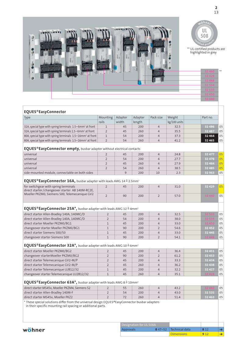
EQUES®EasyConnector Type Mounting Adapter Adapter Pack size Weight Part no.
rails width length kg/100 units
32A, special type with spring terminals 1.5–6mm2 at front 1 45 200
32A, special type with spring terminals 1.5–6mm2 at front 2 45 260
80A, special type with spring terminals 1.5–16mm2 at front 1 54 200
80A, special type with spring terminals 1.5–16mm2 at front 2 54 260
EQUES®EasyConnector empty, busbar adapter without electrical contacts
universal 2 45 200
universal 2 54 200
universal 2 45 260
universal 2 54 260
side-mounted module, connectable on both sides 9 200
EQUES®EasyConnector 16A, busbar adapter with leads AWG 14 =̂ 2.5mm2
for switchgear with spring terminals 2 45 200direct starter /changeover starter AB 140M-RC2E,Moeller PKZM0, Siemens S00, Telemecanique GV2 2 90 200
EQUES®EasyConnector 25A*, busbar adapter with leads AWG 12 =̂ 4mm2
direct starter Allen-Bradley 140A, 140MC/D 2 45 200
direct starter Allen-Bradley 140A, 140MC/D 2 54 200
direct starter Moeller PKZM0/BG1 1 45 200
changeover starter Moeller PKZM0/BG1 1 90 200
direct starter Siemens S00/S0 1 45 200
changeover starter Siemens S00 1 90 200
EQUES®EasyConnector 32A*, busbar adapter with leads AWG 10 =̂ 6mm2
direct starter Moeller PKZM0/BG2 2 45 200
changeover starterMoeller PKZM0/BG2 2 90 200
direct starter Telemecanique GV2-M/P 2 45 200
direct starter Telemecanique GV2-M/P 2 45 260
direct starter Telemecanique LUB12/32 1 45 200
changeover starter Telemecanique LU2B12/32 1 45 260
EQUES®EasyConnector 63A*, busbar adapter with leads AWG 8 =̂ 10mm2
direct starter MS45x, Moeller PKZM4, Siemens S2 2 55 260
direct starter Allen-Bradley 140M-F 2 54 200
direct starter MS45x, Moeller PKZ2 2 72 260
* These special solutions differ from the universal design EQUES®EasyConnector busbar adaptersin their specific mounting rail spacing or additional parts.
4 32.5 32 486 05
4 35.5 32 487 05
4 37.3 32 464 05
4 41.2 32 465 05
4 24.8 32 477 05
4 27.7 32 478 05
4 27.9 32 484 05
4 38.5 32 485 05
10 2.3 32 963 05
4 31.0 32 429 05
2 57.0 32 440 05
4 32.5 32 533 05
4 38.0 32 534 05
4 33.0 32 450 05
2 54.6 32 452 05
4 33.0 32 445 05
2 54.1 32 448 05
4 36.4 32 451 05
2 61.2 32 453 05
4 33.3 32 434 05
4 36.2 32 438 05
4 32.2 32 427 05
4 35.1 32 428 05
4 43.2 32 460 05
4 43.0 32 535 05
4 51.4 32 463 05
old page 2/12
** UL-certified products arehighlighted in grey
**

214
60mm-system classic630A (800A) / 2500A
Technical data 8 13 ➔
Dimensions 9 14 ➔
Designation for UL 508A
Approvals 8 47–52
New
32 157
32 140
32 575
EQUES®PowerConnector
EQUES®PowerConnector, 3-pole busbar adapter, phase division 23 – 30mm, connection top
Type Adapter Adapter Pack size Weight Part no.
length width kg/100 units
160A for ABB Tmax T1, GE FD160, Schneider Electric NS 80 200 90
125A for Allen-Bradley 140-CMN 200 90
160A for Moeller NZM1 200 90
100A for Siemens S3, ABB MS49x 200 72
EQUES®PowerConnector, 3-pole busbar adapter, phase division 35 – 36mm
290A for ABB Tmax T4, connection top 300 105
250A for Allen-Bradley 140U-J 192 106
250A for Schneider Electric NSX100 –NSX250, GV7 192 106
250A for Moeller NZM2-XKR4 192 106
160A for Siemens 3VL1 UL 192 106
250A for Siemens 3VL2, 3VL3 UL 192 106
225A for Terasaki S250-NJ, connection top 240 105
EQUES®PowerConnector, 3-pole busbar adapter, phase division 43 – 45mm
580A for ABB Tmax T5 270 140
600A for Allen-Bradley 140U-K, -L 272 140
570A for Schneider Electric NSX400, NSX630 272 140
630A for Moeller NZM3-XKR13O 300 140
400A for Siemens 3VL4 295 140
EQUES®PowerConnector, 3-pole busbar adapter, phase division 63mm, connection top
580A for Siemens 3VL5 connection top 325 184
EQUES®PowerConnector, busbar adapter, 4-pole, phase division 35 – 36mm, connection top
250A for ABB Tmax T4 270 140
250A for Schneider Electric NSX100 – NSX250 270 140
250A for Moeller NZM2-XKR4 270 140
250A for Siemens 3VL2, 3VL3 270 140
connection of switch to busbar system at top
EQUES®PowerConnector, busbar adapter, 4-pole, phase division 43 – 45mm, connection top
500A for ABB Tmax T5 300 185
500A for Schneider Electric NS400 – NSX630 300 185
500A for Moeller NZM3-XKR130 300 185
500A for Siemens 3VL400 300 185
connection of switch to busbar system at top
** UL-certified products arehighlighted in grey
**
1 81.0 32 575 05
1 81.0 32 549 05
1 81.0 32 570 05
1 66.5 32 981 05
1 122.6 32 601 05
1 90.0 32 137 05
1 93.8 32 156 05
1 90.1 32 140 05
1 95.3 32 976 05
1 95.3 32 977 05
1 102.0 32 592 05
1 252.7 32 593 05
1 212.0 32 138 05
1 222.6 32 157 05
1 255.7 32 978 05
1 222.4 32 975 05
1 276.0 32 980 05
1 180.0 32 584 05
1 180.0 32 582 05
1 180.0 32 580 05
1 180.0 32 578 05
1 360.0 32 585 05
1 350.0 32 583 05
1 350.0 32 581 05
1 350.0 32 579 05
old page 2/14

215
Technical data 8 13 ➔
Dimensions 9 11 ➔
Approvals 8 47–52
Universal busbar adapter Type Adapter Adapter Pack size Weight Part no.
length width kg/100 units
200A top connection to system 222 108
200A bottom connection to system 222 108
250A top connection to system 320 110
250A bottom connection to system 320 110
for all commercially available switchgear with M4 fixing screws (see accessories for M5 and M6 screws)
Accessories for universal busbar adaptersM5 slide nut for 32 214, 32 215, 32 168 and 32 216
M6 slide nut for 32 214, 32 215, 32 168 and 32 216
Busbar adapter 630A screw M10 top or bottom 320 184
metal accessory plate 320 184
metal accessory plate, without drillings 315 180
All adapters for busbars 12 – 30 x 5 – 10mm, double-T and triple-T section.
1 84.2 32 214 05
1 86.0 32 215 05
1 160.4 32 168 05
1 164.0 32 216 05
4 0.4 32 937 05
4 0.4 32 938 05
1 278.0 32 004 05
1 95.2 32 910 05
1 95.5 32 911 05
old page 2/13
32 168
32 214

60mm-system classic630A (800A) / 2500A
216
old page 2/17
31 071
31 072
31 070
31 442
31 441
31 919
31 918
31 951
31 950
31 947
31 946
Accessories 7 10 ➔
Technical data 8 17 ➔
Dimensions 9 15 ➔
Approvals 8 47–52
CUSTO®EasyLiner, D bus-mounting fuse base shock-protected with strip cover, for gauge ring
Busbars Thread / Rated current / Base width Pack size Weight Part no.
Rated voltage kg/100 units
5, 10 and double-T section E 27 / 25A / 500V 42
E 33 / 63A / 500V 57
CUSTO®EasyLiner, D bus-mounting fuse base shock-protected with strip cover, for gauge screw
5, 10 and double-T section E 27 / 25A / 500V 42
E 33 / 63A / 500V 57
D bus-mounting fuse base, for gauge ring
5, 10 and double-T section E 27 / 25A / 500V 42
E 33 / 63A / 500V 57
D bus-mounting fuse base, for gauge screw
5, 10 and double-T section E 27 / 25A / 500V 42
E 33 / 63A / 500V 57
D strip coverE 27 42
E 33 57
E 27 84
E 33 114
Shock protection, for all strip covers
Type Pack size Weight Part no.
kg/100 units
clips onto side
Labelself-adhesive labels (108 pieces per A5 sheet)
8 29.7 31 946 01
6 39.8 31 947 01
8 28.7 31 950 01
6 38.7 31 951 01
10 23.3 31 918 01
10 32.0 31 919 01
10 22.3 31 441 01
10 30.9 31 442 01
10 4.9 31 070 01
10 6.2 31 071 01
5 8.4 31 072 01
5 10.8 31 073 01
10 1.3 79 663 01
1 0.4 78 801 02

Accessories 7 9 ➔
Technical data 8 16 ➔
Dimensions 9 15 ➔
Approvals 8 47–52
CUSTO®EasyLiner, D0 bus-mounting fuse base shock-protected with strip cover, for gauge ring
Busbars Thread / Rated current / Base width Pack size Weight Part no.
Rated voltage kg/100 units
5, 10 and double-T section E 18 / 63A / 400V* 27
E 18 / 63A / 400V 36
* 36mm wide type provides good lead placement and heat dissipation
D0 bus-mounting fuse base, for gauge ring
5, 10 and double-T section E 18 / 63A / 400V* 27
E 18 / 63A / 400V 36
* 36mm wide type provides good lead placement and heat dissipation
D0 strip coverE 18 27
E 18 36
E 18 54
Shock protection, for all strip covers
Type Pack size Weight Part no.
kg/100 units
clips onto side
8 14.4 31 935 01
6 16.1 31 936 01
10 14.7 01 647 01
10 15.5 01 498 01
10 2.6 01 980 01
10 3.1 01 424 01
10 4.0 01 981 01
10 1.3 79 663 01
217
01 981
01 424
01 980
01 498
01 647
31 936
31 935

218
60mm-system classic630A (800A) / 2500A
Accessories 7 9,13,17,18 ➔
Technical data 8 14,15 ➔
Dimensions 9 15 ➔
Designation for UL 508A
Approvals 8 47–52
SECUR®PowerLiner, bus-mounting switch disconnectors with fuses, 3-pole, 3-pole switching*
Type Rated current/ Pack size Weight Part no.
Rated voltage kg/100 units
for D01 and D02 fuses** 63A / 400V *
for 10 x 38mm NFC cylindrical fuses IEC 60 269-2 32A / 690V *
* Can be converted to 1-pole switching.
** The use of side-mounted module 31 901 is recommended for continuous loads above 35A.Please observe DIN EN 60 439-1 table 1.
SECUR®PowerLiner, bus-mounting switch disconnectors with fuses, with LED, 3-pole, 3-pole switching
for D01 and D02 fuses** 63A / 400V *
* Can be converted to 1-pole switching.
** The use of side-mounted module 31 901 is recommended for continuous loads above 35A.Please observe DIN EN 60 439-1 table 1.
Accessories, for SECUR®PowerLiner
pilot switch
9mm wide side-mounted module
D02 reducer for D01 fuses 2–16A
AMBUS®EasyLiner, bus-mounting fuse base for cylindrical fuses, 3-pole, 3-pole isolating, with spring terminals
for 10 x 38mm fuses IEC 60 269-2 32A / 690V
for 10 x 38mm fuses IEC 60 269-2 with LED 110– 690V AC/DC 32A / 690V
for Class CC fuses UL 248-4 30A / 600V
for Class CC fuses UL 248-4, with LED 110– 600V AC/DC 30A / 600V
AMBUS®EasyLiner, bus-mounting fuse base, 3-pole + N, 4-pole isolating, with spring terminals
for 10 x 38mm fuses IEC 60 269-2 32A / 690V
for 10 x 38mm fuses IEC 60 269-2 with LED 110– 690V AC/DC 32A / 690V
AMBUS®EasyLiner, bus-mounting fuse base, 2-pole, 2-pole isolating, with spring terminals
for 10 x 38mm fuses IEC 60 269-2 32A / 690V
for 10 x 38mm fuses IEC 60 269-2 with LED 110– 690V AC/DC 32A / 690V
for 10 x 38mm fuses IEC 60 269-6 32A / 1000V DC
for 10 x 38mm fuses IEC 60 269-6 with LED 400– 1000V DC 32A / 1000V DC
Fuses are not included in delivery.
1 75.9 31 158 01
1 76.0 31 232 01
1 76.5 31 525 01
1 0.7 31 903 01
5 6.1 31 901 01
20 0.1 31 902 01
4 18.5 31 954 01
4 18.7 31 955 01
4 18.6 31 958 01
4 18.8 31 959 01
4 25.2 31 963 01
4 25.2 31 964 01
6 12.2 31 961 01
6 12.2 31 962 01
6 12.2 31 956 01
6 12.2 31 960 01
31 963
31 525
31 958
31 954
31 961
** UL-certified products are highlighted in grey
**

new page
Accessories 7 11,12,19,20 ➔
Technical data 8 21–25,27–30 ➔
Dimensions 9 16–18,20 ➔
Designation for UL 508A
Approvals 8 47–52
New
QUADRON®CrossLink Technology, module width 106
QUADRON®CrossLinkCarrier NH, bus-mounting fuse base, bottom/top connection, 3-pole
Type Rated Size Pack size Weight Part no.
current kg/100 units
box terminal 70/95mm2 160A 00
connection screw M8 160A 00
with shock protection, without grip lug covers, see page 2/25, 4/3 for additional NH bus-mounting fuse bases
QUADRON®CrossLinkCarrier Class J, bus-mounting fuse base, bottom/top connection, 3-pole
box terminal AWG 14-2/0 str 100A 29 x 117
QUADRON®CrossLinkBreaker NH, bus-mounting fuse switch disconnector, bottom/top connection, 3-pole
box terminal 70/95mm2 160A 00
connection screw M8 160A 00
box terminal 70/95mm2, electronic fuse monitoring 160A 00
connection screw M8, electronic fuse monitoring* 160A 00
electromechanical fuse monitoring see page 2/23
QUADRON®CrossLinkSwitch NH, bus-mounting switch disconnector with fuses, 3-pole, with multifunctional handle (spring-controlled)
connection at bottom, box terminal 70/95mm2 125A 00
connection at top, box terminal 70/95mm2 125A 00
connection at bottom, box terminal 70/95mm2, 125A 00electronic fuse monitoring, 690V AC, 250V DC*
circuit diagram for fuse monitoring on page 9/35
QUADRON®CrossLinkSwitch NH, bus-mounting switch disconnector with fuses, 3-pole, for door coupling drive (spring-controlled)
connection at bottom, box terminal 70/95mm2 125A 00
connection at top, box terminal 70/95mm2 125A 00
QUADRON®CrossLinkSwitch, bus-mounting switch disconnector, 3-pole, with multifunctional handle (spring-controlled)
connection at bottom, box terminal 70/95mm2 160A –
connection at top, box terminal 70/95mm2 160A –
QUADRON®CrossLinkSwitch, bus-mounting switch disconnector, 3-pole, for door coupling drive (spring-controlled)
connection at bottom, box terminal 70/95mm2 160A –
connection at top, box terminal 70/95mm2 160A –
Fuses are not included in delivery.
Devices can be fastened directly on busbars 12, 15, 20, 25, 30 x 5, 10mm, double-T and triple-T section.
* Delivery date on request
1 87.0 03 199 10
1 87.0 03 299 10
1 129.0 33 402 16
1 100.0 33 198 09
1 100.0 33 398 09
1 117.0 33 324 09
1 117.0 33 394 09
1 219.0 33 500 15
1 219.0 33 501 15
1 236.0 33 506 15
1 208.0 33 503 15
1 208.0 33 504 15
1 216.0 33 540 14
1 216.0 33 541 14
1 208.0 33 543 14
1 208.0 33 544 14
219
** UL-certified products arehighlighted in grey
33 911
33 503
33 540
33 506
33 500
33 198
33 402
03 199**

220
60mm-system classic630A (800A) / 2500A
new page
Technical data 8 22,25,27,29 ➔
Dimensions 9 18,33 ➔New
32 594 33 914 33 908 33 911
Accessoriesfor QUADRON®CrossLink Technology, module width 106
QUADRON®CrossLinkAdapter, busbar adapter, 3-pole, phase division 33mm
Type Adapter Adapter Pack size Weight Part no.
length width kg/100 units
for system components with module width 106mm; 200 106to be used as spare slot mounting, busbar cover
for QUADRON®CrossLinkCarrier NH, bus-mounting fuse base, 3-pole
Type Size Pack size Weight Part no.
kg/100 units
grip lug cover, 1 unit required for each fuse 00
cover for cable lugs, can be clipped on top and bottom 00
wedge clamp terminal for screw terminal M8, Cu and Al* conductors 16 – 70mm2 s(r), s(s), f +AE 00
tunnel terminal for screw terminal M8, Cu 3 x 1.5 – 16 mm2 s(r), (03 299)
Cu 3 x 1.5 – 10mm2 f +AE
* not maintenance-free when aluminium conductors are used (see page 8/2)
for QUADRON®CrossLinkBreaker NH, bus-mounting fuse switch disconnector, 3-pole
pilot switch for monitoring the disconnector lid position 000 - 3
lid interlock for sealing wire 00
cover for cable lugs, can be clipped on top and bottom 00
wedge clamp terminal for screw terminal M8, Cu and Al* conductors 16 –70mm2 s(r), s(s), f +AE 00
tunnel terminal for screw terminal M8, Cu 3 x 1.5 – 16 mm2 s(r),(33 398,
Cu 3 x 1.5 – 10mm2 f +AE33 394)
* not maintenance-free when aluminium conductors are used (see page 8/2)
more accessories see page 2/24
for QUADRON®CrossLinkSwitch, NH-bus-mounting switch disconnector with fuses and bus-mounting switch disconnector, 3-pole
Type Can be Pack size Weight Part no.
used with kg/100 units
connection terminal 120mm2 QCS-NH 00,pilot switch for monitoring the switch position QCS 160 A
black door coupling twist handle IP 66, lockable in neutral position, with up to 3 pad locks,
33 503with door interlock33 504
red-yellow door coupling twist handle IP 66, 33 543lockable in neutral position, with up to 3 pad locks,
33 544with door interlock
extension shaft 290mm long
extension shaft 490mm long
switch can also be installed at a 90° angle to the left/right, with the handle in the same position
2 36.5 32 594 09
30 1.2 79 448 10
1 2.8 79 811 09
3 3.0 33 224 09
3 6.4 01 182 09
1 1.1 33 156 09
10 0.2 03 849 09
1 2.8 79 811 09
3 3.0 33 224 09
3 6.4 01 182 09
1 8.8 33 914 14
1 1.1 33 908 14
1 57.0 33 910 14
1 57.0 33 911 14
1 13.0 33 912 14
1 22.0 33 913 14

221
33 911
33 514
33 550
33 516
33 511
Accessories 7 11,12 ➔
Technical data 8 27–29 ➔
Dimensions 9 18,19 ➔New
QUADRON®CrossLinkSwitch, module width 184
QUADRON®CrossLinkSwitch NH, bus-mounting switch disconnector with fuses, 3-pole, with multifunctional handle (spring-controlled)
Type Rated Size Pack size Weight Part no.
current kg/100 units
connection at bottom, connection screw M10* 250A 1
connection at top, connection screw M10* 250A 1
connection at bottom, connection screw M10, 250A 1electronic fuse monitoring, 690V AC, 250V DC*
circuit diagram for fuse monitoring on page 9/35
QUADRON®CrossLinkSwitch NH, bus-mounting switch disconnector with fuses, 3-pole, for door coupling drive (spring-controlled)
connection at bottom, connection screw M10* 250A 1
connection at top, connection screw M10* 250A 1
QUADRON®CrossLinkSwitch, bus-mounting switch disconnector, 3-pole, with multifunctional handle (spring-controlled)
connection at bottom, connection screw M10* 320A –
connection at top, connection screw M10* 320A –
QUADRON®CrossLinkSwitch, bus-mounting switch disconnector, 3-pole, for door coupling drive (spring-controlled)
connection at bottom, connection screw M10* 320A –
connection at top, connection screw M10* 320A –
Fuses are not included in delivery.
Devices can be fastened directly on busbars 12, 15, 20, 25, 30 x 5, 10mm, double-T and triple-T section.
1 567.0 33 510 15
1 589.0 33 511 15
1 575.0 33 516 15
1 555.0 33 513 15
1 577.0 33 514 15
1 565.0 33 550 14
1 587.0 33 551 14
1 543.0 33 553 14
1 565.0 33 554 14

222
60mm-system classic630A (800A) / 2500A
Technichal data 8 27,29 ➔
Dimensions 9 18,33 ➔New
Accessoriesfor QUADRON®CrossLinkSwitch, module width 184
CoverType Can be used Pack size Weight Part no.
with kg/100 units
for cable lug, can be clipped on top or bottom QCS-NH 1,QCS 320 A
Pilot switchfor monitoring the disconnector lid position QCS-NH 1,
QCS 320 A
Door coupling twist handle lockable in neutral position, IP 66, with up to 3 pad locks, with door interlock
black 33 513, 33 514,red-yellow 33 553, 33 554
switch can also be installed at a 90° angle to the left/right, with the handle in the same position
Extension shaft 290mm lang 33 513, 33 514,490mm lang 33 553, 33 554
Connection accessoriesbox terminal for Cu conductors 35 - 150 mm2
s(r), f, f + AE; fl. Cu
clamp connector for Cu conductors 70 - 150mm2
s(r), f + AE; fl. Cu QCS-NH 1,
wedge clamp terminal, single, for Cu and Al* conductors 70- 150 mm2 QCS 320 As(r), s(s), f, f + AE
wedge clamp terminal, double, for Cu conductors 2 x 35 - 70mm2
s(r), s(s), f + AE
* not maintenance-free when aluminium conductors are used (see page 8/2)
33 908 33 911 33 909 33 145
2 10.7 33 142 09
1 1.1 33 908 14
1 57.0 33 910 14
1 57.0 33 911 14
1 13.0 33 912 14
1 22.0 33 913 14
3 10.0 33 909 09
1 6.3 33 163 09
1 11.6 33 166 09
1 16.6 33 145 09

223
33 603
33 602
33 601
Accessories 7 11,12 ➔
Technical data 8 23,24,25 ➔
Dimensions 9 16,17 ➔
Approvals 9 47–52
QUADRON®CrossLinkBreaker NH sizes 000 to 3, bus-mounting fuse switch disconnector, bottom/top connection, 3-pole
Type Rated Size Pack size Weight Part no.
current kg/100 units
box terminal 50mm2 125A 000
box terminal 70/95mm2 160A 00
connection screw M8 160A 00
connection screw M10 250A 1
connection screw M10 400A 2
connection screw M12 630A 3
QUADRON®CrossLinkBreaker sizes 00 to 3, bus-mounting fuse switch disconnector, bottom/top connection, 3-pole, with electronic fuse monitoring
box terminal 70/95mm2 160A 00
screw M8* 160A 00
connection screw M10 250A 1
connection screw M10 400A 2
connection screw M12 630A 3
QUADRON®CrossLinkBreaker sizes 00 to 3, bus-mounting fuse switch disconnector, bottom/top connection, 3-pole, with electromechanical fuse monitoring
clamp 70mm2/screw M8 160A 00
connection screw M10 250A 1
connection screw M10 400A 2
connection screw M12 630A 3
circuit diagram for fuse monitoring on page 9/35
Conversion kit for 5mm busbars 1 – 2
for mounting on 12, 15, 20, 25 und 30 x 5mm busbars for QUADRON®CrossLinkBreaker sizes 1 and 2
Devices can be fastened directly on busbars 12, 15, 20, 25, 30 x 5, 10mm, double-T and triple-T section. Conversion kit 33 148 is required for mounting sizes 1 and 2 onto 5mm busbars, size 3 is not suitable for 5mm busbars.
* Delivery date on request
1 113.0 33 216 09
1 100.0 33 198 09
1 100.0 33 398 09
1 340.0 33 601 09
1 522.0 33 602 09
1 756.0 33 603 09
1 117.0 33 324 09
1 117.0 33 394 09
1 398.0 33 325 09
1 572.0 33 326 09
1 796.0 33 327 09
1 180.0 33 206 09
1 424.0 33 160 09
1 574.0 33 161 09
1 824.0 33 162 09
1 6.5 33 148 09

224
60mm-system classic630A (800A) / 2500A
Dimensions 9 16,33 ➔
33 316
33 142
33 315
33 317
old page 2/21
Accessoriesfor QUADRON®CrossLinkBreaker
Equalising trim for adjusting the installation depth
Type Dimensions Size Pack size Weight Part no.
W x H kg/100 units
equalising trim 2 sections 106 x 350 00
trim strip 20 x 350 00
cover for cable lug top and bottom 184 x 350 1(2 units are required)
equalising trim 2 sections 210 x 350 2
for mask cutout up to 340 high, 83 in front of the front edge of the busbar
Cover, for cable lug
can be clipped on top or bottom 00
1
2
3
Barrier for handleto close off handle area from rear 1 – 3
Pilot switch, for monitoring disconnector lid position
1 changeover switch 250V AC / 5A; 30V DC / 4A 000 – 3
Disconnector lid interlock, to seal the disconnector
for sealing wire 000
00
for 3 padlocks with hasp diameter 4 – 7mm 1 – 3
Connection accessoriesType Connection Size Pack size Weight Part no.
mm2 kg/100 units
clamp connector for Cu conductors, 70 – 150/18 x 2 – 14 1s(r), f + AE, fl. Cu 120 – 240/21 x 1 – 14 2
150 – 300/25 x 1 – 13 3
wedge clamp terminal, single, for 16 – 70 00 (33 398, 33 394, 33 206)Cu and Al* conductors, s(r), s(s), f, f + AE 70 – 150 1
50 – 150/120 – 240 2
150 – 300 3
wedge clamp terminal, double, 2 x 35 – 70 1 (33 601, 33 325)for Cu conductors, s(r), s(s), f + AE 2 x 70 – 120 2 (33 602, 33 326)
2 x 150 3 (33 603, 33 327)
2 x 185 3 (33 603, 33 327)
tunnel terminal 3 x 1.5 – 16 00 (33 398, 33 394, 33 206)
1 12.4 33 315 09
2 6.0 33 317 09
2 10.7 33 142 09
1 21.1 33 316 09
1 2.8 79 811 09
2 10.7 33 142 09
2 10.9 33 143 09
2 15.6 33 144 09
10 2.2 33 155 09
1 1.1 33 156 09
10 0.1 33 051 09
10 0.2 03 849 09
10 0.5 33 157 09
1 6.3 33 163 09
1 10.6 33 164 09
1 12.5 33 165 09
3 3.0 33 224 09
1 11.6 33 166 09
1 19.9 33 167 09
1 24.7 33 168 09
1 16.6 33 145 09
1 27.8 33 146 09
1 36.8 33 147 09
1 36.8 33 385 09
3 6.4 01 182 09

225
Accessories 7 11,12 ➔
Technical data 8 22 ➔
Dimensions 9 15,16 ➔
03 520
79 449
03 704
79 448
03 654
QUADRON®CrossLinkCarrier NH, bus-mounting fuse base, bottom/top connection, 3-pole
Type Rated Size Pack size Weight Part no.
current kg/100 units
box terminal 70/95mm2 160A 00
connection screw M8 160A 00
with shock protection, without grip lug covers; accessories see page 2/17
QUADRON®CrossLinkCarrier NH can be fastened directly on busbars 12, 15, 20, 25, 30 x 5, 10 mm, double-T and triple-T section.
NH bus-mounting fuse base size 00, 3-pole, top connection
clamp 160A 00
screw M8 160A 00
with shock protection, without grip lug covers
NH bus-mounting fuse base size 1 – 2, 3-pole, connecting terminals at bottom
screw M10 250A 1
screw M10 400A 2
with shock protection, without grip lug covers
Grip lug cover, suitable for NH bases with shock protection
Type Size Pack size Weight Part no.
kg/100 units
1 unit required to cover a fuse 00
2 units required to cover a fuse 1 – 2
Bus-mounting fuse base, 3-pole, connecting terminals at top
Type Rated Internal Connection Pack size Weight Part no.
current gauge mm2 max. kg/100 units
screw M8 160A 80 70
with 2 barriersfor semiconductors (super-fast) fuse links with bolt-on lugs as per DIN 43 653, gauge 80mm
Bus-mounting fuse base, 3-pole, connecting terminals at bottom
screw M10 400A 110 240
with 2 barriersfor semiconductors (super-fast) fuse links with bolt-on lugs as per DIN 43 653, gauge 110mm
NH bus-mounting fuse bases suitable for direct mounting on busbars 12 – 30 x 5 – 10 mm, double-T and triple-T section.For further NH bus-mounting fuse bases see p. 4/3.
1 87.0 03 199 10
1 87.0 03 299 10
4 66.5 03 654 10
4 64.5 03 656 10
1 211.6 03 704 10
1 291.2 03 693 10
30 1.2 79 448 10
30 1.5 79 449 10
4 72.2 03 520 10
1 239.7 03 518 10

old page 2/22
SECUR®LeanStreamer size 00, NH in-line fuse switch disconnector, 3-pole switching, bottom/top connection
Type Rated Size Pack size Weight Part no.
current mm2 kg/100 units
clamp 70mm2/screw M8 160A 00
with terminal compartment cover
SECUR®LeanStreamer size 00, NH in-line fuse switch disconnector, 3-pole switching, bottom/top connection,with electronic fuse monitoring, 400V AC
clamp 70mm2/screw M8 160A 00
with terminal compartment cover
circuit diagram for fuse monitoring on page 9/35
Pilot switch, for monitoring lid position
Type Size Pack size Weight Part no.
kg/100 units
1 changeover switch 250V AC / 5A; 30V DC / 4A 00
flat push-on connector 2.8 x 0.5 (DIN 46 244-A)
Connection accessoriesclamp connector 1.5 – 70mm2 for Cu conductors, s(r), f + AE; fl. Cu 00
M8 screw connector 00
wedge clamp terminal 6–70mm2, for Cu and Al* conductors, s(r), s(s), f + AE 00
* not maintenance-free when aluminium conductors are used (see page 8/2)
Devices can be fastened directly on busbars 12, 15, 20, 25, 30 x 5, 10 mm, double-T and triple-T section.
33 234
Accessories 7 11,12 ➔
Technical data 8 30 ➔
Dimensions 9 21,33 ➔
Approvals 8 47–52
3 146.0 33 234 12
1 146.0 33 285 12
1 1.1 33 156 09
3 1.5 03 727 09
3 1.4 30 894 09
3 3.0 33 224 09
60mm-system classic630A (800A) / 2500A
226

new
227
Mount for fuses in accordance with UL248
AMBUS®EasyLiner, bus-mounting fuse base, 3-pole, 3-pole disconnecting, with spring terminals
Type Width Rated current / Pack size Weight Part no.
Rated voltage kg/100 units
for Class CC 27 30A / 600V
for Class CC, with LED 27 30A / 600V
QUADRON®J-Carrier, complete solution on busbar adapter, 3-pole, 3-pole isolation
for Class J, 21 x 57 108 30A / 600V
for Class J, 21 x 57, with LED 108 30A / 600V
for Class J, 27 x 60 126 60A / 600V
for Class J, 27 x 60, with LED 126 60A / 600V
QUADRON®CrossLinkCarrier Class J, bus-mounting fuse base, bottom/top connection, 3-pole
for Class J, 29 x 117 106 100A / 600 V
for busbars 12, 15, 20, 25 and 30 x 5, 10, double-T and triple-T section
QUADRON®J-Carrier, Class J bus-mounting fuse base, bottom/top connection, 3-pole
Class J, 41 x 146 210 200A / 600V
Class J, 54 x 181 256 400A / 600V
for busbars 12, 15, 20, 25 and 30 x 10, double-T and triple-T section
Accessories 7 17–20 ➔
Technical data 8 15,20,21 ➔
Dimensions 9 20 ➔
Designation for UL 508A
Approvals 8 47–52
old page 2/23
** UL-certified products arehighlighted in grey
**
4 18.6 31 958 01
4 18.8 31 959 01
1 110.0 31 967 16
1 110.0 31 968 16
1 131.0 31 969 16
1 131.0 31 970 16
1 129.0 33 402 16
1 508.0 33 310 16
1 690.0 33 311 16
33 402
31 970
31 968
31 959

Accessories 2 1,2 7 13 ➔
Technical data 8 5,9,15 ➔
Dimensions 9 5,6,8,14 ➔
Designation for UL 508A
Approvals 8 47–52
31 964
31 963
32 146
32 582
01 162
01 485
old page2/24
** UL-certified products arehighlighted in grey
**
228
60mm-system classic630A (800A) / 2500A
10 26.6 01 485 06
4 13.0 01 116 06
4 15.0 01 132 06
1 210.0 01 147 07
1 180.0 01 162 07
1 21.0 01 137 07
1 58.0 01 599 07
2 27.1 01 555 07
1 45.0 01 597 07
4 14.1 32 146 05
1 180.0 32 584 05
1 180.0 32 582 05
1 180.0 32 580 05
1 180.0 32 578 05
1 360.0 32 585 05
1 350.0 32 583 05
1 350.0 32 581 05
1 350.0 32 579 05
4 25.2 31 963 01
4 25.2 31 964 01
4-pole system components
Busbar supportType Pack size Weight Part no.
kg/100 units
4-pole, for flat busbars 12 x 5 – 30 x 10, IEC
1-pole, for double-T section busbar, for connecting to 01 231
1-pole, for triple-T section busbar, for connecting to 01 232
Connection set, 4-pole, for 20 x 5 – 30 x 10, double-T and triple-T profile, without cover cap
560A, for Cu u. Al* 120 – 300mm2, s(r), s(s), f
800A, for fl. Cu and flat busbars up to 32 x 10
* not maintenance-free when aluminium conductors are used (see page 8/2)
System cover, 4-pole
holder set (left + right) for cover sections, 4-pole
front cover section (4-pole), 1100mm long, can only be used with holder no. 01 137
top/bottom cover section, 1100mm long, can only be used with holder no. 01 136 or 01 137
can be used for systems with 12, 20, 25, 30 x 5, 10 busbars, double-T and triple-T section
Cover cap, 4-pole, for 20 x 5 – 30 x 10, double-T and triple-T profile
W x H x D 228 x 260 x 90mm
PE/N module, with 2 connection terminals 16mm2, without cable
Type Adapter Adapter Pack size Weight Part no.
length width kg/100 units
80A, connectable to all EQUES®EasyConnectors 242 18
EQUES®PowerConnector, 4-pole busbar adapter
250A for ABB Tmax T4 270 140
250A for Schneider Electric NSX100 – NSX250 270 140
250A for Moeller NZM2-XKR4 270 140
250A for Siemens 3VL2, 3VL3 270 140
500A for ABB Tmax T5 300 185
500A for Schneider Electric NSX400, NSX630 300 185
500A for Moeller NZM3-XKR13O 300 185
500A for Siemens 3VL400 300 185
Upper connection between switch and busbar system
AMBUS®EasyLiner, bus-mounting fuse base, 3-pole + N, 4-pole isolating, with spring terminals
Type Rated current/ Pack size Weight Part no.
Rated voltage kg/100 units
for 10 x 38 mm cylindrical fuses IEC 60 629-2 32A / 690V
for 10 x 38 mm cylindrical fuses IEC 60 629-2 with LED 32A / 690V