Embed Size (px)
Citation preview

UNIVERSAL CC/CV LED DIMMER ― JAMECO PART NO. 2163938
Experience Level: Intermediate | Time Required: 3 Hours
A versatile kit that can be configured to drive either constant voltage LED arrays or constant current LEDs. Use this kit to dim under-cabinet LED lighting using flexible LED strips or build your own LED desk lamp using high brightness LEDs. The majority of the circuit is identical for both types of LEDs. Two inexpensive NPN transistors and a few resistors are added to the circuit for constant current LEDs. The circuit uses a MOSFET transistor to act either as a digital switch or linear current regulator. Constant voltage LED arrays include built-in current limiting resistors. Typically these arrays come in a flexible tape form (like Vastech 35285M300PW12V LED Ribbon Strip) but may also be constructed from discrete LEDs and appropriate current limiting resistors (for example a string of 3 white LEDs wired in series with a 120 ohm resistor designed to operate at 20mA with a 12VDC power supply). When configured to drive constant voltage LED arrays, the dimmer circuit acts as a digital switch that turns on and off hundreds or thousands of times per second to modulate the LED brightness. Constant current LEDs do not have any built-in current limiting and depend on the dimmer circuit to limit the current. The dimmer circuit is configured to drive 1 Watt High Brightness LEDs (like Ligitek High Power LED Star LGLW-311H) at a regulated 330mA. It can drive one to three High Brightness LEDs wired in series depending on the power supply voltage. The inexpensive precision voltage reference that provides the reference for the micro-controller ADC is also used with a simple current mirror to control the gate voltage based on the current flowing through a current sense resistor providing accurate and temperature stable current limiting. An inexpensive micro-controller and voltage reference provide pro-level features including: - Non-linear 1000:1 dimming range over 256 steps to account for the eye's sensitivity to changes at low intensity levels - Short circuit detection and automatic shutdown with fault indicator - Smooth intensity changes
Required tools and parts: Soldering iron with fine tip Thin rosin-core solder Wire stripper/cutter and basic hand tools Digital multimeter 18AWG Solid core wire 28-30AWG Solid core wire Heat sink grease Kit Includes: 2-Position terminal block 10kΩ Carbon-film resistors 6.8μF Tantalum capacitors 4.7kΩ Carbon-film resistors 0.1μF Ceramic capacitors 470Ω Carbon-film resistors T-1 3/4 (5mm) Red LED 1MΩ Carbon-film resistors MTP3055VL N-Channel transistor LP2950CZ 5V Regulator 3/8" Square cermet potentiometer LM385Z 1.2V Regulator 8-Pin IC socket PIC12F675-I/P 8-bit Microcontroller IC TO-220 Heat sink 11.3Ω Metal-film resistor Prototyping board 10kΩ Metal-film resistor LM393N Dual comparator IC 30kΩ Metal-film resistor
Step 1 - Determine which version of the dimmer you will build Determine which of the two versions of this circuit you will build based on the kind of LEDs you want to dim. The attached guide showing the pinouts of all polarized parts is useful for both versions of the circuit. You may refer back to this as you wire the chosen circuit. Continue to Step #2 if you will be building the Constant Current version to control one to three 1 W High Brightness LEDs wired in series requiring a constant current source. This version of the circuit is documented in the even steps. Skip to Step #3 if you will be building the Constant Voltage version to control a 12 VDC LED Array requiring a constant voltage source. This version of the circuit is documented in the odd steps.
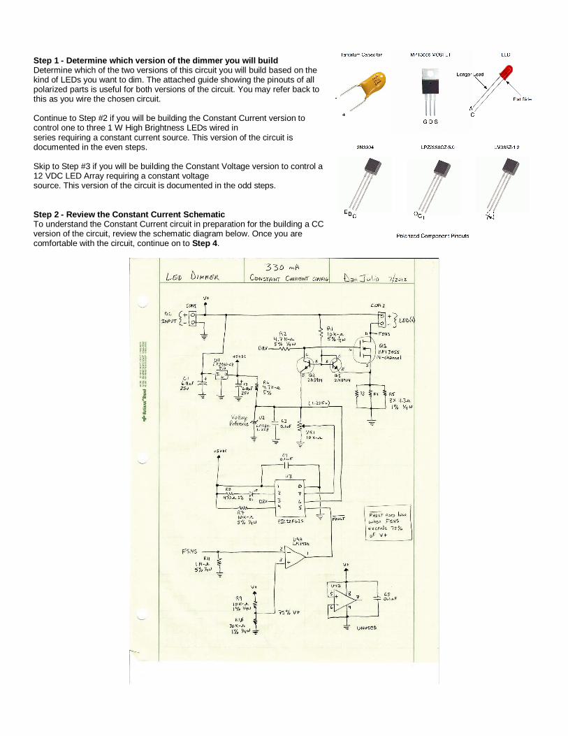
Step 2 - Review the Constant Current Schematic To understand the Constant Current circuit in preparation for the building a CC version of the circuit, review the schematic diagram below. Once you are comfortable with the circuit, continue on to Step 4.

Theory of Operation CON1 connects to the external DC power supply. This supply should be able to supply at least 500mA. The power supply output voltage depends on the number of LEDs that are being driven. The power supply should supply between 2.5V and 3.0V more than the forward voltages of the LEDs. - Use a 6 VDC power supply to drive one 1 W LED - Use a 9 VDC power supply to drive two 1 W LEDs wired in series - Use a 12 VDC power supply to drive three 1 W LEDs wired in series CON2 connects to the LED(s). The "+" terminal connects to the anode and the "-" terminal connects to the cathode. No series resistors are necessary for the CC circuit. U1, C1 and C2 form a regulated 5 VDC power supply for the precision voltage reference, the PIC micro-controller and the LED Fault indicator. C1 and C2 are polarized tantalum capacitors. It is important to ensure the positive terminal is connected to the positive voltage and the negative terminal is connected to ground. These capacitors should be physically adjacent (within 0.5") of U1. R6, U2 and C3 form a precision 1.235V voltage reference. This reference voltage is used as the Vref input to micro-controller ADC as well as the full-scale voltage for the potentiometer VR1 used to control the dimmer intensity. It is also used as the reference for the linear current regulator. R6 limits the current for the voltage reference and C3 adds a small amount of filtering to the output voltage. R1-R5 and Q1-Q3 form the linear current regulator configured to limit the current flowing through the LEDs to approximately 330mA. The N-channel MOSFET Q1 is used in its linear region of operation where the gate voltage controls the current flowing from the drain to source and consequently through the LEDs. Q2 and Q3 are configured as current mirror so that the same current flows through both transistors. Since they are the same type of transistor the Vce voltage will be the same. This forces the Q1 gate voltage to settle at a point that forces the voltage across R3-R5 to be the same as the reference voltage (1.235 volts). R3-R5 are selected so that the reference voltage divided by their parallel resistance is the desired LED current. In this case 1.235V divided by 3.77Ω results in a nominal current of 328mA. The circuit is accurate and relatively insensitive to temperature changes due to the use of the precision voltage and matched current mirror transistors. The DRV signal from the micro-controller through R2 switches the linear regulator on and off in order to dim the LEDs. C4, D1, R7, R8 and U3 form the "brains" of the dimmer. U3 is an inexpensive Microchip PIC 12F625 micro-controller programmed to read and average an input voltage from VR1 (0 to 1.235 volts) and output a series of pulses on the DRV output. The sum of the time the pulses are active set the brightness of the LED. The pulses occur so rapidly that the eye perceives the LED to be constantly on. The length and number of pulses are adjusted by the firmware in a non-linear fashion so that changes at low intensity levels are smaller and more precise than changes at high intensity levels since the human eye is more sensitive to changes at low intensity levels. This gives the dimmer a larger perceived dynamic range and better control at low intensity levels than if a linear PWM function was used. R8 and D1 are used to indicate a fault condition. R7 connects to the micro-controller reset line. C4 is a local bypass capacitor. C5, R9-R11 and U4 form the short-circuit detection circuit. It is possible for a LED to fail in a short-circuit configuration. This could cause excessive current flow through Q1 and generate a lot of heat possibly causing damage. U4 is a simple voltage comparator with the inverting input connected to the LED cathode line. The high-impedance of the comparator input is important in order to prevent a stray current flowing through the LEDs and comparator to turn the LED on. The comparator's non-inverting input is connected to the output of a voltage divider that is configured for 75% of the input voltage. This voltage level is below that voltage across the LEDs when they are turned off. A short circuit in the LEDs will bring the FSNS voltage above 75% of the input voltage and force the comparator output low. The micro-controller immediately detects the low input and disables the DRV output and lights the Fault LED for as long as the fault exists. R11 is a weak pull-down that keeps the input of the comparator from floating too high when the LEDs are turned off. C5 is a bypass capacitor. Step 3 - Review the Constant Voltage Schematic Understand the Constant Voltage circuit in preparation for building a CV version of the circuit. Review the schematic diagram below. Once you are comfortable with the circuit, continue on to Step 5.
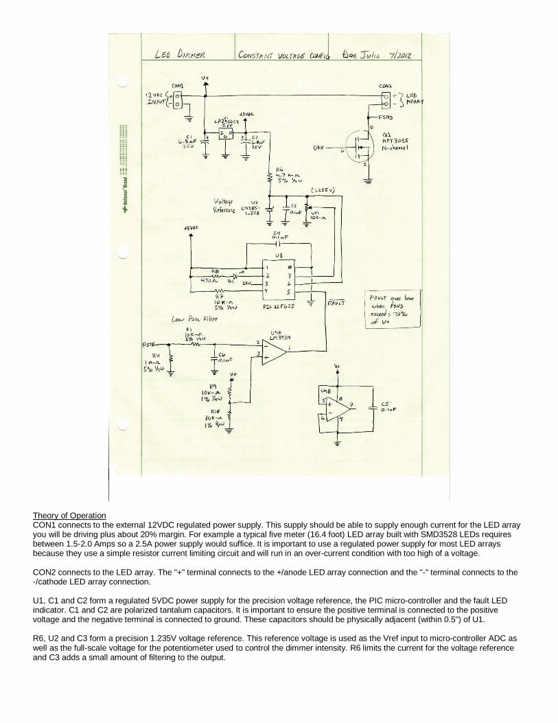
Theory of Operation CON1 connects to the external 12VDC regulated power supply. This supply should be able to supply enough current for the LED array you will be driving plus about 20% margin. For example a typical five meter (16.4 foot) LED array built with SMD3528 LEDs requires between 1.5-2.0 Amps so a 2.5A power supply would suffice. It is important to use a regulated power supply for most LED arrays because they use a simple resistor current limiting circuit and will run in an over-current condition with too high of a voltage. CON2 connects to the LED array. The "+" terminal connects to the +/anode LED array connection and the "-" terminal connects to the -/cathode LED array connection. U1, C1 and C2 form a regulated 5VDC power supply for the precision voltage reference, the PIC micro-controller and the fault LED indicator. C1 and C2 are polarized tantalum capacitors. It is important to ensure the positive terminal is connected to the positive voltage and the negative terminal is connected to ground. These capacitors should be physically adjacent (within 0.5") of U1. R6, U2 and C3 form a precision 1.235V voltage reference. This reference voltage is used as the Vref input to micro-controller ADC as well as the full-scale voltage for the potentiometer used to control the dimmer intensity. R6 limits the current for the voltage reference and C3 adds a small amount of filtering to the output.

The N-Channel MOSFET Q1 is used as a digital switch. The DRV signal from the micro-controller switches Q1 on and off rapidly in order to dim the LEDs. C4, D1, R7, R8 and U3 form the "brains" of the dimmer. U3 is an inexpensive Microchip PIC 12F625 micro-controller programmed to read and average an input voltage from VR1 (0 to 1.235 volts) and output a series of pulses on the DRV output. The sum of the time the pulses are active set the brightness of the LED. The pulses occur so rapidly that the eye perceives the LED to be constantly on. The length and number of pulses are adjusted by the firmware in a non-linear fashion so that changes at low intensity levels are smaller and more precise than changes at high intensity levels since the human eye is more sensitive to changes at low intensity levels. This gives the dimmer a larger perceived dynamic range and better control at low intensity levels than if a linear PWM function was used. R8 and D1 are used to indicate a fault condition. R7 connects to the micro-controller reset line. C4 is a local bypass capacitor. C5, C6, R1, R9-R11 and U4 form the short-circuit detection circuit. A short circuit in the LED array or its wiring could cause excessive current flow through Q1 and generate a lot of heat possibly causing damage. U4 is a simple voltage comparator with the inverting input connected to the LED array (-) connection through a low-pass filter comprised of R1 and C6. The low-pass filter prevents ringing that occurs because of the long wiring distances in a LED array from inadvertently triggering a fault condition. The high-impedance of the comparator input is important in order to prevent a stray current flowing through the LEDs and comparator to turn the LEDs on. The comparator's non-inverting input is connected to the output of a voltage divider that is configured for 75% of the input voltage. This voltage level is below that voltage across the LEDs when they are turned off. A short circuit in the LED array will bring the FSNS voltage above 75% of the input voltage and force the comparator output low. The micro-controller immediately detects the low input and disables the DRV output and lights the Fault LED for as long as the fault exists. R11 is a weak pull-down that keeps the input of the comparator from floating too high when the LEDs are turned off. C5 is a bypass capacitor. Step 4 - Load Parts for Constant Current Version Please refer to the parts placement diagram and schematic shown in Step 2. In addition, briefly skip ahead to Step 6 to familiarize yourself with how the parts will be wired together and then come back to this step. In this step you will mount and solder the components to the protoboard. Please proceed with the following steps in sequence. Refer to the parts placement diagram for the location of each component. When all components have been mounted, proceed to Step 6. 1. Install the MOSFET transistor and heatsink. - Drill a hole in the protoboard as shown in the parts placement diagram. The hole is drilled centered in the lead hole on the third full row down and on the 7th column from the left of the protoboard. - Bend the leads of the MOSFET at a 90 degree angle so that when the MOSFET is positioned aligned with the hole; the leads enter the protoboard on the 10th full row down. - Put a small dab of heatsink grease on the backside of the MOSFET and then fit it on heatsink and attach to the protoboard using the screw and nut. - Solder the MOSFET leads to the bottom of the board and trim away the excess leads. 2. Solder the two connectors to the top of the board with the lead entry facing out from the board. 3. Position and solder the two 8-pin IC sockets as shown on the placement diagram. 4. Position and solder the potentiometer, VR1, as shown on the placement diagram. Its left-most pin goes on the 19th full row down and the 6th column. Trim away the excess leads. 5. Attach C1, C2 and U1. Note that the positive lead of both tantalum capacitors is on the outside edge of the protoboard. Trim away the excess capacitor leads. Bend the input lead of U1 so it contacts C1's positive lead and solder. Bend the output lead of U1 so it contacts C2's positive lead and solder. Bend the ground lead of U1 so it can make contact with a ground wire that will run between the negative leads of both capacitors. 6. Attach C3, R6 and U2 as shown in the placement diagram. Solder R6 and trim away the excess leads. Solder U2 and trim away the excess leads. Bend the lower of C3's leads so that it connects to both R6 and U2 and solder. Trim away the excess. Bend the upper of C3's leads so it connects to U2 and solder. Trim away the excess. 7. Insert and solder Q2 and Q3 as shown on the placement diagram. Trim away the excess leads. 8. Bend the leads of R1 as shown in the placement diagram so the upper lead enters the protoboard above C1's positive connection and the lower lead enters the protoboard on the 11th full row down. Solder and trim away the excess leads. 9. Bend the leads of R2 as shown in the placement diagram so that the upper lead enters the protoboard on the 10th full row down and the bottom lead enters the protoboard on the 16th full row down. Bend the upper lead so it connects to Q1's gate and solder. Bend the lower lead so it connects to U3 pin 3 and solder. Trim away the excess leads. 10. Insert R7 as shown on the placement diagram. Bend the upper lead so it connects to U3 pin 1 and solder. Bend the lower lead so it connects to U3 pin 4 and solder. Trim away the excess leads.
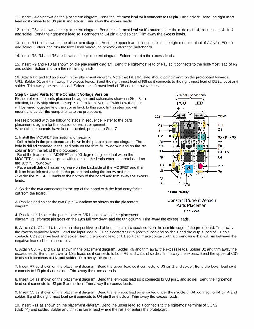
11. Insert C4 as shown on the placement diagram. Bend the left-most lead so it connects to U3 pin 1 and solder. Bend the right-most lead so it connects to U3 pin 8 and solder. Trim away the excess leads. 12. Insert C5 as shown on the placement diagram. Bend the left-most lead so it’s routed under the middle of U4, connect to U4 pin 4 and solder. Bend the right-most lead so it connects to U4 pin 8 and solder. Trim away the excess leads. 13. Insert R11 as shown on the placement diagram. Bend the upper lead so it connects to the right-most terminal of CON2 (LED "-") and solder. Solder and trim the lower lead where the resistor enters the protoboard. 14. Insert R3, R4 and R5 as shown on the placement diagram. Solder and trim the excess leads. 15. Insert R9 and R10 as shown on the placement diagram. Bend the right-most lead of R10 so it connects to the right-most lead of R9 and solder. Solder and trim the remaining leads. 16. Attach D1 and R8 as shown in the placement diagram. Note that D1's flat side should point inward on the protoboard towards VR1. Solder D1 and trim away the excess leads. Bend the right-most lead of R8 so it connects to the right-most lead of D1 (anode) and solder. Trim away the excess lead. Solder the left-most lead of R8 and trim away the excess. Step 5 - Load Parts for the Constant Voltage Version Please refer to the parts placement diagram and schematic shown in Step 3. In addition, briefly skip ahead to Step 7 to familiarize yourself with how the parts will be wired together and then come back to this step. In this step you will mount and solder the components to the protoboard. Please proceed with the following steps in sequence. Refer to the parts placement diagram for the location of each component. When all components have been mounted, proceed to Step 7. 1. Install the MOSFET transistor and heatsink. - Drill a hole in the protoboard as shown in the parts placement diagram. The hole is drilled centered in the lead hole on the third full row down and on the 7th column from the left of the protoboard. - Bend the leads of the MOSFET at a 90 degree angle so that when the MOSFET is positioned aligned with the hole, the leads enter the protoboard on the 10th full row down. - Put a small dab of heatsink grease on the backside of the MOSFET and then fit it on heatsink and attach to the protoboard using the screw and nut. - Solder the MOSFET leads to the bottom of the board and trim away the excess leads. 2. Solder the two connectors to the top of the board with the lead entry facing out from the board. 3. Position and solder the two 8-pin IC sockets as shown on the placement diagram. 4. Position and solder the potentiometer, VR1, as shown on the placement diagram. Its left-most pin goes on the 19th full row down and the 6th column. Trim away the excess leads. 5. Attach C1, C2 and U1. Note that the positive lead of both tantalum capacitors is on the outside edge of the protoboard. Trim away the excess capacitor leads. Bend the input lead of U1 so it contacts C1's positive lead and solder. Bend the output lead of U1 so it contacts C2's positive lead and solder. Bend the ground lead of U1 so it can make contact with a ground wire that will run between the negative leads of both capacitors. 6. Attach C3, R6 and U2 as shown in the placement diagram. Solder R6 and trim away the excess leads. Solder U2 and trim away the excess leads. Bend the lower of C3's leads so it connects to both R6 and U2 and solder. Trim away the excess. Bend the upper of C3's leads so it connects to U2 and solder. Trim away the excess. 7. Insert R7 as shown on the placement diagram. Bend the upper lead so it connects to U3 pin 1 and solder. Bend the lower lead so it connects to U3 pin 4 and solder. Trim away the excess leads. 8. Insert C4 as shown on the placement diagram. Bend the left-most lead so it connects to U3 pin 1 and solder. Bend the right-most lead so it connects to U3 pin 8 and solder. Trim away the excess leads. 9. Insert C5 as shown on the placement diagram. Bend the left-most lead so is routed under the middle of U4, connect to U4 pin 4 and solder. Bend the right-most lead so it connects to U4 pin 8 and solder. Trim away the excess leads. 10. Insert R11 as shown on the placement diagram. Bend the upper lead so it connects to the right-most terminal of CON2 (LED "-") and solder. Solder and trim the lower lead where the resistor enters the protoboard.
11. Insert R1 and C6 as shown on the placement diagram. Solder R1 and trim away the excess leads. Bend the upper lead of C6 so it connects to the lower-lead of R1 and solder. Trim away the excess lead. Bend the lower lead of C6 so it connects to U4 pin 4 and solder. Trim away the excess lead. 12. Insert R9 and R10 as shown on the placement diagram. Bend the right-most lead of R10 so it connects to the right-most lead of R9 and solder. Solder and trim the remaining leads. 13. Attach D1 and R8 as shown in the placement diagram. Note that D1's flat side should point inward on the protoboard towards VR1. Solder D1 and trim away the excess leads. Bend the right-most lead of R8 so it connects to the right-most lead of D1 (anode) and solder. Trim away the excess lead. Solder the left-most lead of R8 and trim away the excess.
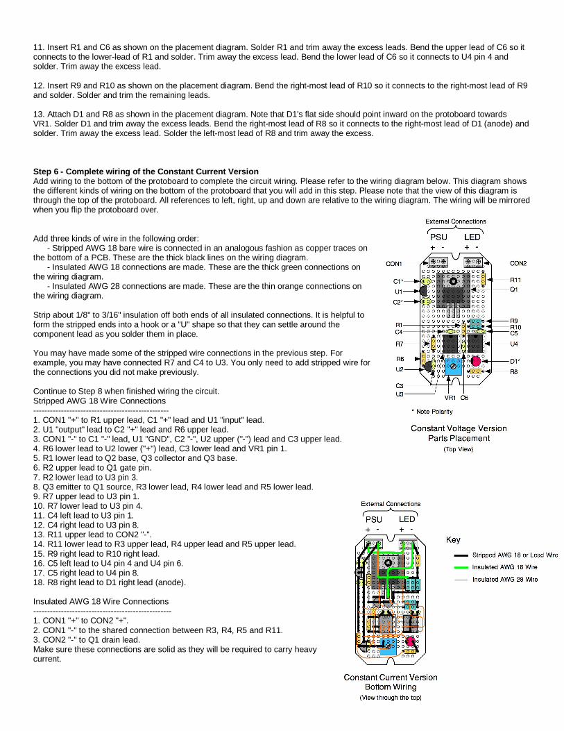
Step 6 - Complete wiring of the Constant Current Version Add wiring to the bottom of the protoboard to complete the circuit wiring. Please refer to the wiring diagram below. This diagram shows the different kinds of wiring on the bottom of the protoboard that you will add in this step. Please note that the view of this diagram is through the top of the protoboard. All references to left, right, up and down are relative to the wiring diagram. The wiring will be mirrored when you flip the protoboard over.
Add three kinds of wire in the following order: - Stripped AWG 18 bare wire is connected in an analogous fashion as copper traces on the bottom of a PCB. These are the thick black lines on the wiring diagram. - Insulated AWG 18 connections are made. These are the thick green connections on the wiring diagram. - Insulated AWG 28 connections are made. These are the thin orange connections on the wiring diagram. Strip about 1/8" to 3/16" insulation off both ends of all insulated connections. It is helpful to form the stripped ends into a hook or a "U" shape so that they can settle around the component lead as you solder them in place. You may have made some of the stripped wire connections in the previous step. For example, you may have connected R7 and C4 to U3. You only need to add stripped wire for the connections you did not make previously. Continue to Step 8 when finished wiring the circuit. Stripped AWG 18 Wire Connections ------------------------------------------------- 1. CON1 "+" to R1 upper lead, C1 "+" lead and U1 "input" lead. 2. U1 "output" lead to C2 "+" lead and R6 upper lead. 3. CON1 "-" to C1 "-" lead, U1 "GND", C2 "-", U2 upper ("-") lead and C3 upper lead. 4. R6 lower lead to U2 lower ("+") lead, C3 lower lead and VR1 pin 1. 5. R1 lower lead to Q2 base, Q3 collector and Q3 base. 6. R2 upper lead to Q1 gate pin. 7. R2 lower lead to U3 pin 3. 8. Q3 emitter to Q1 source, R3 lower lead, R4 lower lead and R5 lower lead. 9. R7 upper lead to U3 pin 1. 10. R7 lower lead to U3 pin 4. 11. C4 left lead to U3 pin 1. 12. C4 right lead to U3 pin 8. 13. R11 upper lead to CON2 "-". 14. R11 lower lead to R3 upper lead, R4 upper lead and R5 upper lead. 15. R9 right lead to R10 right lead. 16. C5 left lead to U4 pin 4 and U4 pin 6. 17. C5 right lead to U4 pin 8. 18. R8 right lead to D1 right lead (anode). Insulated AWG 18 Wire Connections -------------------------------------------------- 1. CON1 "+" to CON2 "+". 2. CON1 "-" to the shared connection between R3, R4, R5 and R11. 3. CON2 "-" to Q1 drain lead. Make sure these connections are solid as they will be required to carry heavy current.
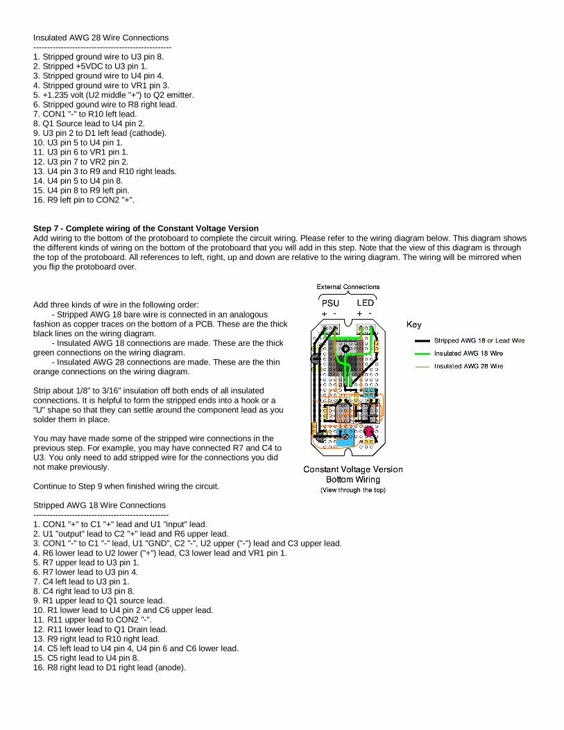
Insulated AWG 28 Wire Connections -------------------------------------------------- 1. Stripped ground wire to U3 pin 8. 2. Stripped +5VDC to U3 pin 1. 3. Stripped ground wire to U4 pin 4. 4. Stripped ground wire to VR1 pin 3. 5. +1.235 volt (U2 middle "+") to Q2 emitter. 6. Stripped gound wire to R8 right lead. 7. CON1 "-" to R10 left lead. 8. Q1 Source lead to U4 pin 2. 9. U3 pin 2 to D1 left lead (cathode). 10. U3 pin 5 to U4 pin 1. 11. U3 pin 6 to VR1 pin 1. 12. U3 pin 7 to VR2 pin 2. 13. U4 pin 3 to R9 and R10 right leads. 14. U4 pin 5 to U4 pin 8. 15. U4 pin 8 to R9 left pin. 16. R9 left pin to CON2 "+". Step 7 - Complete wiring of the Constant Voltage Version Add wiring to the bottom of the protoboard to complete the circuit wiring. Please refer to the wiring diagram below. This diagram shows the different kinds of wiring on the bottom of the protoboard that you will add in this step. Note that the view of this diagram is through the top of the protoboard. All references to left, right, up and down are relative to the wiring diagram. The wiring will be mirrored when you flip the protoboard over.
Add three kinds of wire in the following order: - Stripped AWG 18 bare wire is connected in an analogous fashion as copper traces on the bottom of a PCB. These are the thick black lines on the wiring diagram. - Insulated AWG 18 connections are made. These are the thick green connections on the wiring diagram. - Insulated AWG 28 connections are made. These are the thin orange connections on the wiring diagram. Strip about 1/8" to 3/16" insulation off both ends of all insulated connections. It is helpful to form the stripped ends into a hook or a "U" shape so that they can settle around the component lead as you solder them in place. You may have made some of the stripped wire connections in the previous step. For example, you may have connected R7 and C4 to U3. You only need to add stripped wire for the connections you did not make previously. Continue to Step 9 when finished wiring the circuit. Stripped AWG 18 Wire Connections ------------------------------------------------- 1. CON1 "+" to C1 "+" lead and U1 "input" lead. 2. U1 "output" lead to C2 "+" lead and R6 upper lead. 3. CON1 "-" to C1 "-" lead, U1 "GND", C2 "-", U2 upper ("-") lead and C3 upper lead. 4. R6 lower lead to U2 lower ("+") lead, C3 lower lead and VR1 pin 1. 5. R7 upper lead to U3 pin 1. 6. R7 lower lead to U3 pin 4. 7. C4 left lead to U3 pin 1. 8. C4 right lead to U3 pin 8. 9. R1 upper lead to Q1 source lead. 10. R1 lower lead to U4 pin 2 and C6 upper lead. 11. R11 upper lead to CON2 "-". 12. R11 lower lead to Q1 Drain lead. 13. R9 right lead to R10 right lead. 14. C5 left lead to U4 pin 4, U4 pin 6 and C6 lower lead. 15. C5 right lead to U4 pin 8. 16. R8 right lead to D1 right lead (anode).
Insulated AWG 18 Wire Connections -------------------------------------------------- 1. CON1 "+" to CON2 "+". 2. CON1 "-" to Q1 source lead. 3. CON2 "-" to Q1 drain lead. Make sure these connections are solid as they will be required to carry heavy current. Insulated AWG 28 Wire Connections -------------------------------------------------- 1. Stripped ground wire to U3 pin 8. 2. Stripped +5VDC to U3 pin 1. 3. Stripped ground wire to U4 pin 4. 4. Stripped ground wire to VR1 pin 3. 5. Stripped ground wire to R8 right lead. 6. CON1 "-" to R10 left lead. 7. Q1 Gate lead to U3 pin 3. 8. U3 pin 2 to D1 left lead (cathode). 9. U3 pin 5 to U4 pin 1. 10. U3 pin 6 to VR1 pin 1. 11. U3 pin 7 to VR2 pin 2. 12. U4 pin 3 to R9 and R10 right leads. 13. U4 pin 5 to U4 pin 8. 14. U4 pin 8 to R9 left pin. 15. R9 left pin to CON2 "+". Step 8 - Test completed Constant Current Version In addition to the LEDs and appropriate power supply, it may be handy to have a voltmeter capable of measuring the power supply output voltage, +5 Volts and 1.235 volts. It is always helpful to have one final look at your completed circuit and compare it against the schematic and layout and wiring diagrams before applying power. Once you are satisfied that you have correctly built the circuit, the following steps should get you up and running. 1. Test voltages before installing the PIC micro-controller (U3) and comparator (U4).
a. Connect your power supply to the dimmer circuit. The power supply should be off. b. Set the voltmeter to a range that can display the power supply voltage. Touch the voltmeter "+" probe to U4 socket pin 8. Touch the voltmeter "-" probe to U4 socket pin 4. c. Switch the power supply on (or plug it in). The voltmeter should read the nominal voltage of the power supply. Quickly switch the power supply off if this is not the case. If this is not the case then there is probably a short somewhere in the V+ related circuitry. Fix this before continuing to Step d. d. Set the voltmeter to a range that can measure 5 volts. Switch the power supply on. Touch the voltmeter "+" probe to U3 socket pin 1. Touch the voltmeter "-" probe to U3 socket pin 8. You should measure approximately 5 volts. If this is not the case then there is a problem in the voltage regulator or +5 volt wiring. Fix this before continuing to Step e. e. Set the voltmeter to a range that can measure 1.235 volts. Switch the power supply on. Touch the voltmeter "+" probe to U3 socket pin 6. Touch the voltmeter "-" probe to U3 socket pin 8. You should measure approximately 1.235 volts. If this is not the case then there is probably a problem in the voltage reference circuit. Fix this before continuing to Step f. f. Set the voltmeter to a range that can measure 75% of the power supply voltage. Switch the power supply on. Touch the voltmeter "+" probe to U4 socket pin 3. Touch the voltmeter "-" probe to U4 socket pin 4. You should measure approximately 0.75 X Power Supply voltage. If this is not the case then there is probably a problem in the voltage divider circuit. Fix this before moving to Step 2.
2. Insert the LM393 IC into the U4 socket. Connect a jumper between U3 socket pin 2 and U3 socket pin 5. Connect a second jumper between U3 socket pin 3 and U3 socket pin 8. Connect a third jumper across the two terminals of CON2. Switch the power supply on. The red fault LED should light up. If it does not light up then there is a problem with the fault detection circuitry. Fix this before moving to Step 3. Remove the jumpers. 3. Insert the pre-programmed PIC 12F675 micro-controller into the U3 socket. Connect your LED(s) to CON2. More than one LED should be wired in series with the cathode of one connected to the anode of the next. The unconnected anode in the chain should be connected to CON2 "+". The unconnected cathode in the chain should be connected to CON2 "-". Make sure the LEDs have adequate heat sinking. Make sure VR1 is turned fully counter-clockwise. Switch on the power supply. The red fault LED may blink briefly. Slowly rotate VR1 clockwise and verify the LEDs light and get brighter, If they do not light or the red fault LED lights then there is probably a wiring problem with the micro-controller or linear regulator. The output of VR1 should vary from 0 to 1.235 volts as it is rotated. The nFAULT input should be high if FSNS is less than the output of the voltage divider R9 and R10. The voltage across R3, R4 and R5 should be 1.235 volts when the dimmer is at full intensity. This completes the testing. The unit is now ready for operation.
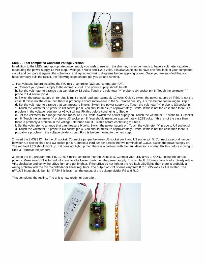
Step 9 - Test completed Constant Voltage Version In addition to the LEDs and appropriate power supply you wish to use with the dimmer, it may be handy to have a voltmeter capable of measuring the power supply 12 Volt output voltage, 5 Volts and 1.235 volts. It is always helpful to have one final look at your completed circuit and compare it against the schematic and layout and wiring diagrams before applying power. Once you are satisfied that you have correctly built the circuit, the following steps should get you up and running. 1. Test voltages before installing the PIC micro-controller (U3) and comparator (U4).
a. Connect your power supply to the dimmer circuit. The power supply should be off. b. Set the voltmeter to a range that can display 12 volts. Touch the voltmeter "+" probe to U4 socket pin 8. Touch the voltmeter "-" probe to U4 socket pin 4. c. Switch the power supply on (or plug it in), it should read approximately 12 volts. Quickly switch the power supply off if this is not the case. If this is not the case then there is probably a short somewhere in the V+ related circuitry. Fix this before continuing to Step d. d. Set the voltmeter to a range that can measure 5 volts. Switch the power supply on. Touch the voltmeter "+" probe to U3 socket pin 1. Touch the voltmeter "-" probe to U3 socket pin 8. You should measure approximately 5 volts. If this is not the case then there is a problem in the voltage regulator or +5 volt wiring. Fix this before continuing to Step e. e. Set the voltmeter to a range that can measure 1.235 volts. Switch the power supply on. Touch the voltmeter "+" probe to U3 socket pin 6. Touch the voltmeter "-" probe to U3 socket pin 8. You should measure approximately 1.235 volts. If this is not the case then there is probably a problem in the voltage reference circuit. Fix this before continuing to Step f. f. Set the voltmeter to a range that can measure 9 volts. Switch the power supply on. Touch the voltmeter "+" probe to U4 socket pin 3. Touch the voltmeter "-" probe to U4 socket pin 4. You should measure approximately 9 volts. If this is not the case then there is probably a problem in the voltage divider circuit. Fix this before moving to the next step.
2. Insert the LM393 IC into the U4 socket. Connect a jumper between U3 socket pin 2 and U3 socket pin 5. Connect a second jumper between U3 socket pin 3 and U3 socket pin 8. Connect a third jumper across the two terminals of CON2. Switch the power supply on. The red fault LED should light up. If it does not light up then there is a problem with the fault detection circuitry. Fix this before moving to Step 3. Remove the jumpers. 3. Insert the pre-programmed PIC 12F675 micro-controller into the U3 socket. Connect your LED array to CON2 noting the correct polarity. Make sure VR1 is turned fully counter-clockwise. Switch on the power supply. The red fault LED may blink briefly. Slowly rotate VR1 clockwise and verify the LEDs light and get brighter. If the LEDs do not light or the red fault LED lights then there is probably a wiring problem with the micro-controller or linear regulator. The output of VR1 should vary from 0 to 1.235 volts as it is rotated. The nFAULT input should be high if FSNS is less than the output of the voltage divider R9 and R10. This completes the testing. The unit is now ready for operation.