Embed Size (px)
Citation preview
CE2N3342en2017-12-05 Building Technologies
3342
RWD62
Universal Controller RWD62For comfort control in HVAC&R-Systems
· Standalone electronic universal controller with P or PI response· Operating voltage in accordance to type AC 24 V· Control application selectable via Application Number· Active input scale can be selectable· Limit and direction of the output scale is able to be freely assigned· Two universal inputs for Ni 1000, Pt 1000 temperature sensors and
DC 0…10 V signals· Unit can be set as °C, °F, % or no specified unit· Two modulating outputs with DC 0…10 V signal outputs, direct or reverse
action· One digital input for day/night changeover· Entering or changing of all data via operating buttons on the controller, possi-
ble without additional tools· PC connection for downloading canned applications via the software tool
Use
The universal controllers are intended for Heating, Ventilating, Air-Conditioning andRefrigeration in comfort control plants. It can be mounted in a control panel or in theARG62.21/ARG62.22 housing on ducts, walls and in plant rooms.
2/10
Siemens RWD62 Universal controller CE2N3342enBuilding Technologies 2017-12-05
HVAC&R Application
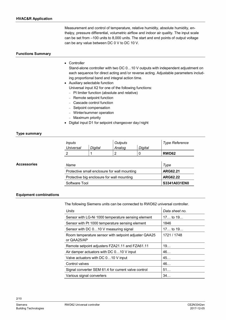
Measurement and control of temperature, relative humidity, absolute humidity, en-thalpy, pressure differential, volumetric airflow and indoor air quality. The input scalecan be set from –100 units to 8,000 units. The start and end points of output voltagecan be any value between DC 0 V to DC 10 V.
Functions Summary
· ControllerStand-alone controller with two DC 0…10 V outputs with independent adjustment oneach sequence for direct acting and/or reverse acting. Adjustable parameters includ-ing proportional band and integral action time.
· Auxiliary selectable functionUniversal input X2 for one of the following functions:- PI limiter function (absolute and relative)- Remote setpoint function- Cascade control function- Setpoint compensation- Winter/summer operation- Maximum priority
· Digital input D1 for setpoint changeover day/night
Type summary
Inputs Outputs Type ReferenceUniversal Digital Analog Digital2 1 2 0 RWD62
Name Type
Protective small enclosure for wall mounting ARG62.21Protective big enclosure for wall mounting ARG62.22Software Tool S3341A031EN0
Equipment combinations
The following Siemens units can be connected to RWD62 universal controller.
Units Data sheet no.
Sensor with LG-Ni 1000 temperature sensing element 17… to 19…Sensor with Pt 1000 temperature sensing element 1846Sensor with DC 0…10 V measuring signal 17… to 19…Room temperature sensor with setpoint adjuster QAA25or QAA25/AP
1721 / 1748
Remote setpoint adjusters FZA21.11 and FZA61.11 19…Air damper actuators with DC 0…10 V input 46…Valve actuators with DC 0…10 V input 45…Control valves 46…Signal converter SEM 61.4 for current valve control 51…Various signal converters 34…
Accessories

3/10
Siemens RWD62 Universal controller CE2N3342enBuilding Technologies 2017-12-05
Other combinations with third-party units are possible, provided the input and outputspecifications match the RWD62.
A software tool for controller application selection and parameter adjustment is avail-able. It is a user-friendly Windows® 95 (or above) based software tool which providesyou a printout of the controller settings.
Functions
The RWD62 is a stand-alone universal controller, which performs both primary andauxiliary control functions. The respective mode is defined by entering the correspond-ing configuration and setting parameters via the push buttons on the controller or thesoftware tool.
The RWD62 controller can be programmed as follows:One sequence: Y1 or Y2 reverse or direct actingTwo sequence: Y1 and Y2 reverse and direct acting or
Y1 and Y2 reverse and reverse acting orY1 and Y2 direct and direct acting
Y1
Out
put
Volta
ge
SetpointLoad
3342
d01
3342
d02
Y1
Out
put
Vol
tage
Load
Y2
Setpoint
Reverse acting sequence(application no.: 10…19)
2 Reverse acting sequences(application no.: 20…29)
Y1
SetpointLoad
Y2
3342
d03O
utpu
tV
olta
ge Y1
SetpointLoad33
42d0
4Out
put
Vol
tage
Reverse and direct acting sequences(application no.: 30…39)
Direct acting sequence(application no.: 40…49)
3342
d05O
utpu
tV
olta
ge
Y1
SetpointLoad
Y2
2 Direct acting sequences(application no.: 50…59)
Software Tool
Controller type
Main functions
4/10
Siemens RWD62 Universal controller CE2N3342enBuilding Technologies 2017-12-05
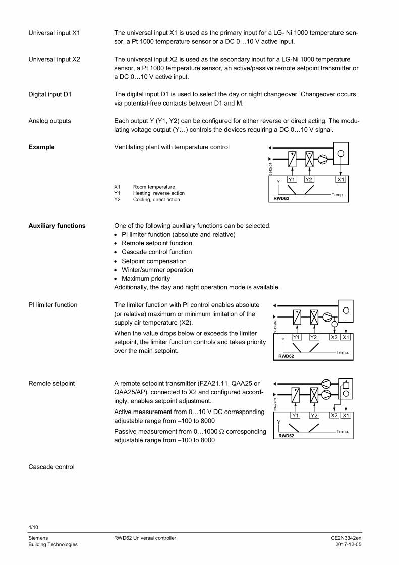
The universal input X1 is used as the primary input for a LG- Ni 1000 temperature sen-sor, a Pt 1000 temperature sensor or a DC 0…10 V active input.
The universal input X2 is used as the secondary input for a LG-Ni 1000 temperaturesensor, a Pt 1000 temperature sensor, an active/passive remote setpoint transmitter ora DC 0…10 V active input.
The digital input D1 is used to select the day or night changeover. Changeover occursvia potential-free contacts between D1 and M.
Each output Y (Y1, Y2) can be configured for either reverse or direct acting. The modu-lating voltage output (Y…) controls the devices requiring a DC 0…10 V signal.
Ventilating plant with temperature control
X1 Room temperatureY1 Heating, reverse actionY2 Cooling, direct action
X1Y2Y1
Temp.RWD62
Y
3342
s01
One of the following auxiliary functions can be selected:· PI limiter function (absolute and relative)· Remote setpoint function· Cascade control function· Setpoint compensation· Winter/summer operation· Maximum priorityAdditionally, the day and night operation mode is available.
The limiter function with PI control enables absolute(or relative) maximum or minimum limitation of thesupply air temperature (X2).
When the value drops below or exceeds the limitersetpoint, the limiter function controls and takes priorityover the main setpoint.
X1Y2Y1
Temp.RWD62
Y X2
3342
s02
A remote setpoint transmitter (FZA21.11, QAA25 orQAA25/AP), connected to X2 and configured accord-ingly, enables setpoint adjustment.
Active measurement from 0…10 V DC correspondingadjustable range from –100 to 8000
Passive measurement from 0…1000 W correspondingadjustable range from –100 to 8000
X1Y2Y1
Temp.RWD62
YX2
3342
s03
Universal input X1
Universal input X2
Digital input D1
Analog outputs
Example
Auxiliary functions
PI limiter function
Remote setpoint
Cascade control

5/10
Siemens RWD62 Universal controller CE2N3342enBuilding Technologies 2017-12-05
X2 Supply air temperature sensor
You can select the PI/PI room/supply airtemperature cascade control. In this case, thevirtual PI room temperature controller determinesthe setpoint within the limiter setpoints for the PIsupply air temperature controller.
X1Y2Y1
Temp.RWD62
Y X2
3342
s04
Maximum priority, coolingIf the value (0…10 V) of the input X2 is greater thanthe calculated output of the cooling sequence, theoutput will use the X2 input value as output value.This is active even when the controller is workingwith the heating sequence.
X2Y2Y1
Temp.RWD62
YX1
3342
s05
The temperature setpoint X1 is shifted by the tem-perature as measured at sensor X2.
Configuration of the RWD62 defines the influenceon setpoint X1.
The example shows the room air temperaturesetpoint as controlled by the outside temperature.
3342
s06
X2Y1
Temp.RWD62
YX1
A digital switch or analogue input between termi-nals X2 and M can be used to implement win-ter/summer changeover.
Digital changeoverWhen the contact is closed, summer operation isselected. Reverse acting output (Y1 only) is setto direct action (cooling).
Analog changeoverWhen the X2 input exceeds the setpoint, sum-mer operation is selected. Reverse acting output(Y1 only) is set to direct action (cooling).
X1Y2Y1
Temp.RWD62
Y
T
X2
3342
s07
A contact between terminals D1 and M can beused to implement setpoint changeover forday/night operation.
When the contact is open, the setpoints for dayoperation are selected.
When the contact is closed, the setpoints for nightoperation are selected.
During the night mode, the following auxiliary func-tions are disabled: remote setpoint, abso-lute/relative limiter, setpoint compensation andmaximum priority.
X1Y2Y1
Temp.RWD62
YD1
3342
s08
Maximum priority
Setpoint compensation
Winter/summeroperation
Day/night setpoint

6/10
Siemens RWD62 Universal controller CE2N3342enBuilding Technologies 2017-12-05
Mechanical design
The RWD62 universal controller is as per DIN 43 880 Gr. 1 requirements.
A protective housing is used to protect the controller when mounted outside a controlpanel, such as on ducts, walls and in plant rooms. Furthermore, the protective housingprevents inadvertent contact with voltage supplying parts such as the connecting termi-nals.The RWD62 clips into the protective housing.The cable entries are located at the top and the bottom of the protective housing.The front has an opening for the LCD display and the programming buttons.
The RWD62 universal controller can be mounted as follows:· In a standard electrical control cabinet as per DIN 43 880· Wall mounted in a protective housing· Front mounting with standard available installation elements
Plug-in screw terminals
The RWD62 is operated by the buttons on the controller front. Additional tools are notnecessary. A 9-pin port is provided for optional programming via the software tool.
3342
z01
The LCD shows the following information for normal operation:
· Current operating values (maximum 4 digits)· Current setpoints (day/night)· Application number· Output voltage value· Control sequencing diagram· Auxiliary input value· Selected auxiliary function
The controller has three operating buttons for the following functions:
The SELECT button is used to enter or save the value adjustment.
The operating buttons are used for viewing and adjusting parameters.
To configure the controller, follow the instructions supplied with the controller.
Engineering notes
Use this controller only for applications as described in the description on the title page(bold print) and the section "Use". Additionally, observe all conditions and restrictionsimposed in this section and in "Technical data".
Housing
Protective housingARG62.21/ARG62.22
Mounting options
Terminals
Operating and displayelements
LCD
Operating buttons
SELECT
Configuration
Intended use

7/10
Siemens RWD62 Universal controller CE2N3342enBuilding Technologies 2017-12-05
The sections marked with a warning symbol contain technical safety requirements andrestrictions. Observe all of these warnings as they directly relate to the protection ofperson and equipment.
Installation notes
Observe all local installation and mounting regulations.The RWD62 controllers can be mounted as follows:A On a top hat rail (EN60715, 35 × 7.5) at least 120 mm longB Wall mounted with 2 screwsC Front mounted using standard elements, e.g.
1 × top hat rail 150 mm long 2 × hexagonal placeholders 50 mm washers and screws
D In the ARG62.21/ARG62.22 protective housing
Standard cables can be used for the controller. However, when mounting in an envi-ronment greatly exposed to EMI, use only shielded cables.
The RWD62 is designed for AC 24 V operating voltage.
The low voltage must comply with the requirements for safety extra-low voltage (SELV)as per EN 60730.
Use safety insulating transformers with double insulation as per EN 60742; they mustbe designed for 100 % on-time.
When using several transformers in one system, the connection terminals G0 must begalvanically connected.
Supplying voltages above AC 24 V to low voltage connections may damage or destroythe controller or any other connected devices. Additionally, connections to voltagesexceeding AC 42 V endanger personal safety.
Commissioning notes
A booklet is supplied with the RWD62 controller for commissioning.Observe the following:· The controller must be configured for plant-specific operation using standard applica-
tion number· Plant specific fine tuning can be performed if required (refer to the commissioning
booklet)· Power supply to the controller and the connected devices must be guaranteed· Values and settings entered remain available even on power failure
Electrical installation
8/10
Siemens RWD62 Universal controller CE2N3342enBuilding Technologies 2017-12-05
Disposal
Technical data
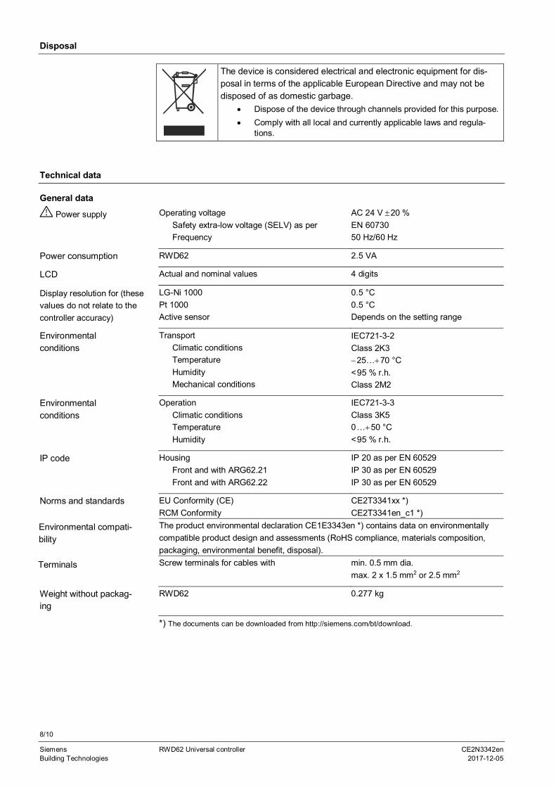
Operating voltageSafety extra-low voltage (SELV) as perFrequency
AC 24 V ±20 %EN 6073050 Hz/60 Hz
RWD62 2.5 VA
Actual and nominal values 4 digits
LG-Ni 1000Pt 1000Active sensor
0.5 °C0.5 °CDepends on the setting range
TransportClimatic conditionsTemperatureHumidityMechanical conditions
IEC721-3-2Class 2K3-25…+70 °C<95 % r.h.Class 2M2
OperationClimatic conditionsTemperatureHumidity
IEC721-3-3Class 3K50…+50 °C<95 % r.h.
HousingFront and with ARG62.21Front and with ARG62.22
IP 20 as per EN 60529IP 30 as per EN 60529IP 30 as per EN 60529
EU Conformity (CE)RCM Conformity
CE2T3341xx *)CE2T3341en_c1 *)
The product environmental declaration CE1E3343en *) contains data on environmentallycompatible product design and assessments (RoHS compliance, materials composition,packaging, environmental benefit, disposal).Screw terminals for cables with min. 0.5 mm dia.
max. 2 x 1.5 mm2 or 2.5 mm2
RWD62 0.277 kg
*) The documents can be downloaded from http://siemens.com/bt/download.
The device is considered electrical and electronic equipment for dis-posal in terms of the applicable European Directive and may not bedisposed of as domestic garbage.
· Dispose of the device through channels provided for this purpose.· Comply with all local and currently applicable laws and regula-
tions.
General data
Power supply
Power consumption
LCD
Display resolution for (thesevalues do not relate to thecontroller accuracy)
Environmentalconditions
Environmentalconditions
IP code
Norms and standards
Terminals
Weight without packag-ing
Environmental compati-bility

9/10
Siemens RWD62 Universal controller CE2N3342enBuilding Technologies 2017-12-05
Controller measuring rangeMax. cable length for dia. 0.6 mm
-50…+150 °Cmax. 300 m
Controller measuring rangeMax. cable length for dia. 0.6 mm
-20…+180 °Cmax. 300 m
Range
Max. cable length for dia. 0.6 mm
DC 0…10 V corresponding to adjustablerange from –100 to 8000 (°C, °F, % orno unit)max. 300 m
Range
Max. cable length for dia. 0.6 mm
0…1000 W corresponding to adjustablerange from –100 to 8000 (°C, °F, % orno unit)max. 300 m
Polling voltage for control commands (D…M)Current consumption
DC 15 V<15 mA
RangeMaximum current
DC 0…10 V±1 m A
Internal diagram
G0
RWD62
Y2
D1 M X1 M X2 MG
MY1 M
Tool
3342
g01
D1 Digital inputG, G0 AC 24 V supply
( SELV AC 24 V power supply)M Ground (G0) for signal inputs, universal inputs and analog outputsX1 Signal input (main input: LS Ni 1000, Pt 1000 and 0…10 V DC)X2 Signal input (aux. input: LS Ni 1000, Pt 1000, 0 …10 V DC and 0…1000 W or
0…10 V DC remote setpoint)Y1, Y2 Analog outputsTool Communication port for PC (9-pin plug)
Connection diagram
Analog inputs X1, X2LG-Ni 1000 W at 0 °C
Pt 1000 W at 0 °C
Analog voltages(for measured variablesin °C, % or without unit)
Remote setpoints X2
Digital input D1
Analog outputs Y1, Y2

10/10
Siemens RWD62 Universal controller CE2N3342enBuilding Technologies 2017-12-05
N1 RWD62 controllerPC Personal computerS1 Time clock or switchX1 Main input (Termination G appears when X1 is an active sensor)X2 Auxiliary input or remote setpoint (Termination G appears when X2 is an active sensor)Y1, Y2 Valve actuator 1 and 2 / damper actuator 1 and 2
Please note that if you use a DESKTOP computer, the TOOL signal ground is gal-vanically connected to G0 inside the controller. If the signal line of the computer isgrounded to Earth, the G0 line after TOOL connection will be Earthed as well.
This will change from SELV to a PELV.
Dimensions
ARG62.21 = 150
200
61.5
48.5
ARG62.22 = 345
Published by:Siemens Switzerland Ltd.Building Technologies DivisionInternational HeadquartersGubelstrasse 226301 ZugSwitzerlandTel. +41 58-724 24 24
www.siemens.com/buildingtechnologies
© Siemens Switzerland Ltd 2017
Delivery and technical specifications subject to change
Note
RWD62
ARG62.21 / ARG62.22