Embed Size (px)
Citation preview
8/12/2019 Universal Design Guidelines
http://slidepdf.com/reader/full/universal-design-guidelines 1/103

8/12/2019 Universal Design Guidelines
http://slidepdf.com/reader/full/universal-design-guidelines 2/103
8/12/2019 Universal Design Guidelines
http://slidepdf.com/reader/full/universal-design-guidelines 3/103
1. Carparks................................... 01a. Parking lots
b. Access lobbies
2. Entrances..................................07a. Drop-off zones
b. Lobbies
3. Horizontal circulation.................13a. Corridors/General
b. Corridors/Orientation
c. Seatings
4. Vertical circulation.....................21a. Staircases/General
Staircases/Treads and risers
Staircases/Handrails
Staircases/Escape
b. Ramps/General
Ramps/Landings
Ramps/Handrails
Ramps/Safety
5. Mechanical circulation...............39a. Lifts/Lift lobbies
Lifts/Lift cars
b. Escalators/Safety features
6. Facilities....................................47a. Information counters
b. Nursing rooms
c. Toilets/Planning and design
Toilets/Compartments
Toilets/Doors
Toilets/Wheelchair-friendly
Toilets/Urinals
Toilets/Wash basins
Toilets/Accessories
d. Playgrounds
7. Retail.........................................71a. Retail/Supermarkets
b. Retail/Shops and kiosks
8. Food and beverage...................77a. Foodcourts and cafes
03
05
09
11
15
17
19
25
27
29
31
33
35
23
41
43
45
49
51
53
55
57
59
63
65
67
69
73
75
79
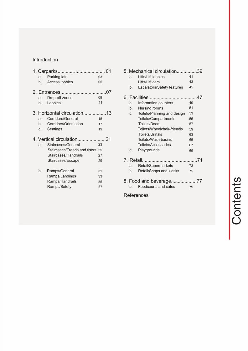
Introduction
References
37
C o n t e n t s
8/12/2019 Universal Design Guidelines
http://slidepdf.com/reader/full/universal-design-guidelines 4/103
I n t r
o d u c t i o n
Universal Design, in the broadest term, is “design for all people”. It seeks to create an environment
addressing the needs for all age groups and people of different abilities including temporary
disability. The move towards universal design has developed due to the expanding population
of people with varying degree of abilities and advancing years, their demands for recognition
and desire for independent living. Ronald Mace, the architect who coined the term “universal
design” said that one of the more important changes brought about by the use of this term is
the elimination of the label “special needs” from segments of the population who are working to
maintain or gain their independence.1 The Universal Design and Americans with Disabilities Act
state that people should be viewed as equal in nature, as having similar rights and obligations,
and as deserving of equal opportunity in every facet of society.
The introduction of Universal Design will no doubt add a new dimension in the accessibility
landscape and has great influence towards the field of design. The designer and building
owner/developer hold the key to create an environment allowing people with different
levels of physical and/or cognitive capabilities to move independently so as to integrate
as fully as possible into the mainstream of daily life. For all design professions, it is
certainly a fast expanding area of practice.
In Singapore, the relevant authorities are also targeting at more innovative and friendly design
to improve usability and livability for everyone. It is the intention of the Building and Construction
Authority (BCA) to instill awareness among designers and building owners/developers who have
the influence to cater for the full range of human needs and be sensitive to incorporate them in
the design.
______________________________________________________________________________________________
1 Null, Roberta L. and Cherry, Kenneth F. Universal Design: Creative Solutions for Americans with Disabilities Act
Compliance, Professional Publications, Inc., Belmont, California, USA, 1998, p25.
8/12/2019 Universal Design Guidelines
http://slidepdf.com/reader/full/universal-design-guidelines 5/103
Principles of Universal Design
Universal Design is a continuous process of innovation targeted at improving usability for
everyone. According to Ronald Mace, Universal Design is the design of products and environment
to be usable by all people, to the greatest extent possible, without the need for adaptation or
specialised design.
The Seven Principles of Universal Design, developed by the Centre for Universal Design, North
Carolina State University with a consortium of universal design researchers and practitioners
from across the United States2
, are :
Equitable Use
The design is useful and marketable to people with diverse abilities.
Flexibility in Use
The design accommodates a wide range of individual preferences and abilities.
Simple and Intuitive
Use of the design is easy to understand, regardless of the user’s experience, knowledge,
language skills, or current concentration level.
______________________________________________________________________________________________
2 © Copyright 2006 The Centre for Universal Design, NC State University Raleigh, North Carolina, USA
8/12/2019 Universal Design Guidelines
http://slidepdf.com/reader/full/universal-design-guidelines 6/103
Perceptible Information
The design communicates necessary information effectively to the user, regardless of ambient
conditions or the user’s sensory abilities.
Tolerance for Error
The design minimizes hazards and the adverse consequences of accidental or unintended
actions.
Low Physical Effort
The design can be used efficiently and comfortably and with a minimum of fatigue.
Size and Space for Approach and Use
Appropriate size and space is provided for approach, reach, manipulation, and use regardless
of user’s body size, posture, or mobility.
8/12/2019 Universal Design Guidelines
http://slidepdf.com/reader/full/universal-design-guidelines 7/103
Universal Design in Singapore
While Universal Design has been widely practiced internationally, it has also been addressed in
Singapore. Besides the Code of Barrier-Free Accessibility in Buildings, first introduced in 1990,
which was essentially weighted towards wheelchair users, Universal Design guidelines were
incorporated in the later revisions with recommendations on good practices in design for people
of all abilities.
From statistics, it is noted that the population age status has been on an upwards move. Both
globally and in Singapore, a demographic change has been experienced. Owing to a healthierlifestyle, life expectancy has now increased to 83.2 years and the proportion of people aged
above 65 will increase from 8.4% in 2005 to 18.7% by 2030. With the advancement of medical
services, more and more people are able to survive illnesses and accidents although some may
result in physical disability.
Thus, in the planning of a city as well as in the design of buildings, special considerations should
be applied to accommodate the needs of the community.
8/12/2019 Universal Design Guidelines
http://slidepdf.com/reader/full/universal-design-guidelines 8/103
Towards a Universal Design Environment
Singapore, being a small island state has placed great emphasis on its planning to ensure the
efficient use of the limited resources. The 2001 Concept Plan of Singapore envisioned to develop
Singapore towards a thriving world class city in the 21st century. It establishes the strategies to
develop Singapore into a dynamic city, a distinctive city and at the same time a delightful city. At
the implementation level, BCA envisions a built environment that incorporates universal design
and will transform Singapore into an accessible and user-friendly city for all.
ConnectivityIn the planning and urban design of the city, considerations have been given to ensure
connectivity. Overhead bridges and underground passes have been provided generously to
allow safe and free movement without the interference of traffic. These facilities should also be
enjoyed by people with disabilities. This should also be extended to achieve interconnectivity
between buildings and urban spaces. These seamless movements are particularly crucial for
a world class city.
Tropical Climate
Our tropical climate is characterised by heavy rainfall and intense heat. In universal design,
protection from these elements is of utmost importance. For outdoor and in-between spaces,
roof protection and floor drainage are essential. Safety measures such as the use of non-slip
floor material, installation of handrail and warning signs would help reduce chances of slipping
and falling.
8/12/2019 Universal Design Guidelines
http://slidepdf.com/reader/full/universal-design-guidelines 9/103
Objectives
With the commitment that all people with different abilities should continue to be integrated with
the society, BCA aims to derive a set of guidelines that provide data and information essential to
achieve universal design with the goal to cater for the usability, safety, comfort and convenience
for all people in the design process.
The specific objectives are:
To assist urban designers and architects to better address the needs of people of differentabilities.
To promote a greater sensitivity and innovation in universal design beyond minimum
requirements.
To achieve a higher standard of universal design for the built environment.
8/12/2019 Universal Design Guidelines
http://slidepdf.com/reader/full/universal-design-guidelines 10/103
Scope
Universal design could be accomplished through a good appreciation of the broad range of
abilities or disabilities of all user groups in the community. Thus, this book gives the full range of
requirements and sets out guidelines for designers to work towards an accessible environment
for the independent living of people of varying abilities.
The book begins with the needs of people of different abilities:
Infants and Children In public buildings, particularly shopping centres and recreation centres, facilities should be
“family friendly”. Provision of play equipment and nursing spaces is highly recommended.
Consideration should also be given to the special needs of and the appropriate scale for
children. In the micro design, the material and the design detail need to be non-hazardous
such as the use of non-toxic and non-breakable materials and the avoidance of sharp corners.
Appropriate height for furniture, sanitary equipment, grab bars and drinking fountains is also
an important aspect.
Expectant Mothers
Expectant mothers also have special needs. Therefore priority in the use of facilities such as
the lifts and rest areas should be accorded to them.
8/12/2019 Universal Design Guidelines
http://slidepdf.com/reader/full/universal-design-guidelines 11/103
Elderly
Today, there is a greater proportion of elderly living independently. The main concerns are
their reduced mobility, limited strength, range of reach, poor eyesight and hearing, etc. Walkingmay no longer be easy. This may be aggravated by less stable gait, poorer eyesight and hence
changes in floor level may not be easily discerned.
Wheelchair Users
Wheelchair users should be able to access all public places. There are two categories of
wheelchair users: those who are able to move independently and others who require
assistance. In the design of the built environment, consideration should be given to betterfacilitate the independent wheelchair users such as the provision of gentler ramps and more
easily operated doors and equipment to ease their mobility.
Physically Injured Persons
A physical injury suffered could be temporary or permanent and in most instances, likely to
result in unstable and slow movement. The person may need crutches or other aids. Provisions
such as automatic doors and sensor control tabs would be desirable.
8/12/2019 Universal Design Guidelines
http://slidepdf.com/reader/full/universal-design-guidelines 12/103
Sightless or Partially Sighted Persons
All people with vision impairment will rely on whatever vision they have as well as other aids
to find their way around. Provision of physical and other sensory cues such as touch, sound,smell as well as tactile or audible information are therefore important aids for them to move
independently.
Hearing Impaired Persons
It is important to understand the unique needs of the deaf or hearing impaired. Since they
are unable to receive audio information, all information should be transmitted through other
means, for example substituting audio alerts with visual alerts and allowing users to configurefrequency and volume of audible cues.
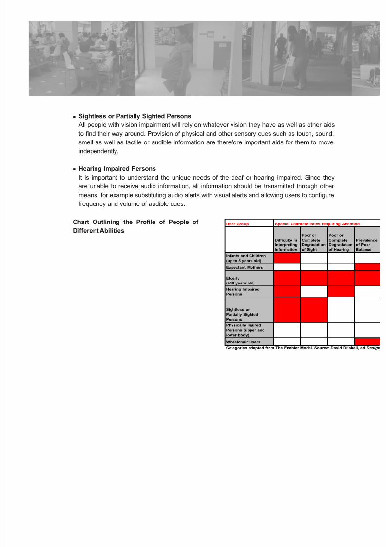
User Group Special Characteristics Requiring Attention
Difficulty in
Interpreting
Information
Poor or
Complete
Degradation
of Sight
Poor or
Complete
Degradation
of Hearing
Prevalence
of Poor
Balance
Infants and Children
(up to 8 years old)
Expectant Mothers
Elderly
(>50 years old)
Hearing Impaired
Persons
Sightless or
Partially Sighted
Persons
Physically Injured
Persons (upper and
lower body)
Wheelchair Users
Categories adapted from The Enabler Model. Source: David Driskell, ed. Design
Chart Outlining the Profile of People of
Different Abilities
8/12/2019 Universal Design Guidelines
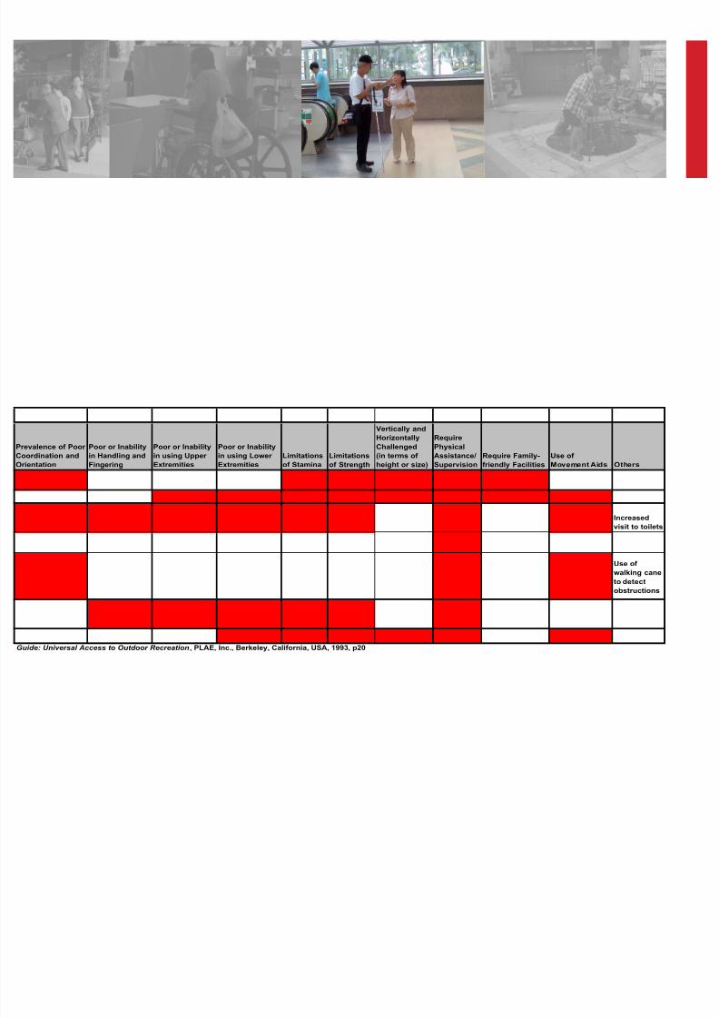
http://slidepdf.com/reader/full/universal-design-guidelines 13/103
Prevalence of Poor
Coordination and
Orientation
Poor or Inability
in Handling and
Fingering
Poor or Inability
in using Upper
Extremities
Poor or Inability
in using Lower
Extremities
Limitations
of Stamina
Limitations
of Strength
Vertically and
Horizontally
Challenged
(in terms of
height or size)
Require
Physical
Assistance/
Supervision
Require Family-
friendly Facilities
Use of
Movement Aids Others
Increased
visit to toilets
Use of
walking cane
to detect
obstructions
Guide: Universal Access to Outdoor Recreation , PLAE, Inc., Berkeley, California, USA, 1993, p20
8/12/2019 Universal Design Guidelines
http://slidepdf.com/reader/full/universal-design-guidelines 14/103
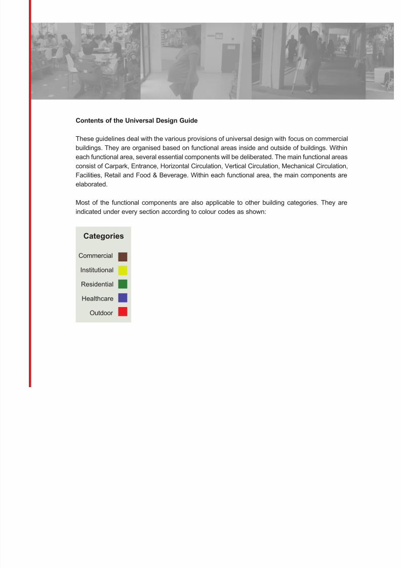
Contents of the Universal Design Guide
These guidelines deal with the various provisions of universal design with focus on commercialbuildings. They are organised based on functional areas inside and outside of buildings. Within
each functional area, several essential components will be deliberated. The main functional areas
consist of Carpark, Entrance, Horizontal Circulation, Vertical Circulation, Mechanical Circulation,
Facilities, Retail and Food & Beverage. Within each functional area, the main components are
elaborated.
Most of the functional components are also applicable to other building categories. They areindicated under every section according to colour codes as shown:
Categories
Commercial
Institutional
Residential
Healthcare
Outdoor
8/12/2019 Universal Design Guidelines
http://slidepdf.com/reader/full/universal-design-guidelines 15/103
Generally, each component has two to four pages. At the top section of the page is the introduction
of the component and design concerns together with photograph(s) as an example. The relevant
building categories, represented in colour codes, will also be included in this section. The maindata is given in point form with photographs illustrating the concerns. Drawings are added to
further explain the guidelines. References to existing relevant Singapore Codes and guidelines
are also indicated for ease of cross-referencing. They include Code on Barrier-Free Accessibility
in Buildings (BFA), Code of Practice for Fire Precautions in Building, and A Guide to Better
Public Toilet Design and Maintenance.
Conclusion
The importance and the benefits of universal design are widely recognised. Universal design
increases the mobility and communication of people, which helps to integrate people of different
abilities into the mainstream daily life. It enables everyone to enjoy the built environment and live
a quality life. This “all inclusive” society that addresses the individual’s special needs will lead to
innovative and creative response in the design of built environment.
It is hoped that this guide, which is first of its series, will set a new benchmark of universaldesign that encourages innovative ways in meeting functional needs without compromising
aesthetics.
8/12/2019 Universal Design Guidelines
http://slidepdf.com/reader/full/universal-design-guidelines 16/103
1
8/12/2019 Universal Design Guidelines
http://slidepdf.com/reader/full/universal-design-guidelines 17/103
1
C a r p a r k s
2
8/12/2019 Universal Design Guidelines
http://slidepdf.com/reader/full/universal-design-guidelines 18/103
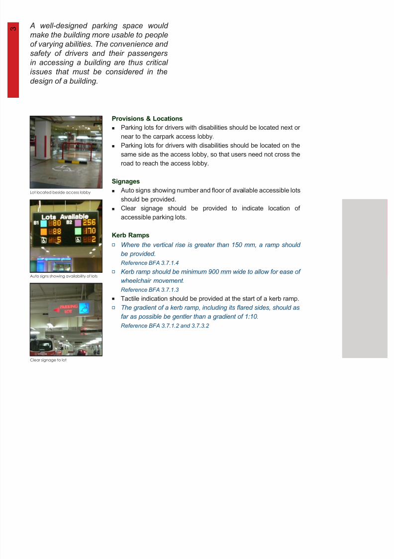
Where the vertical rise is greater than 150 mm, a ramp should
be provided.
Reference BFA 3.7.1.4
Kerb ramp should be minimum 900 mm wide to allow for ease of
wheelchair movement.
Reference BFA 3.7.1.3
Tactile indication should be provided at the start of a kerb ramp.
The gradient of a kerb ramp, including its flared sides, should as
far as possible be gentler than a gradient of 1:10.
Reference BFA 3.7.1.2 and 3.7.3.2
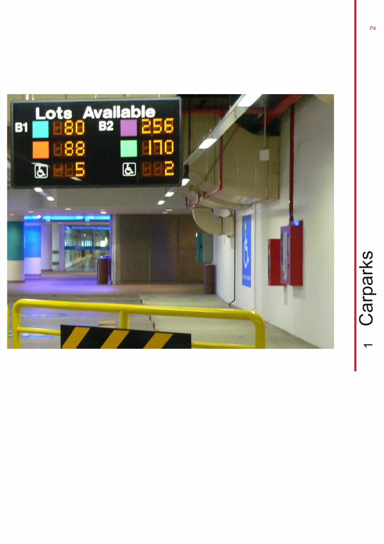
Auto signs showing availability of lots
Lot located beside access lobby
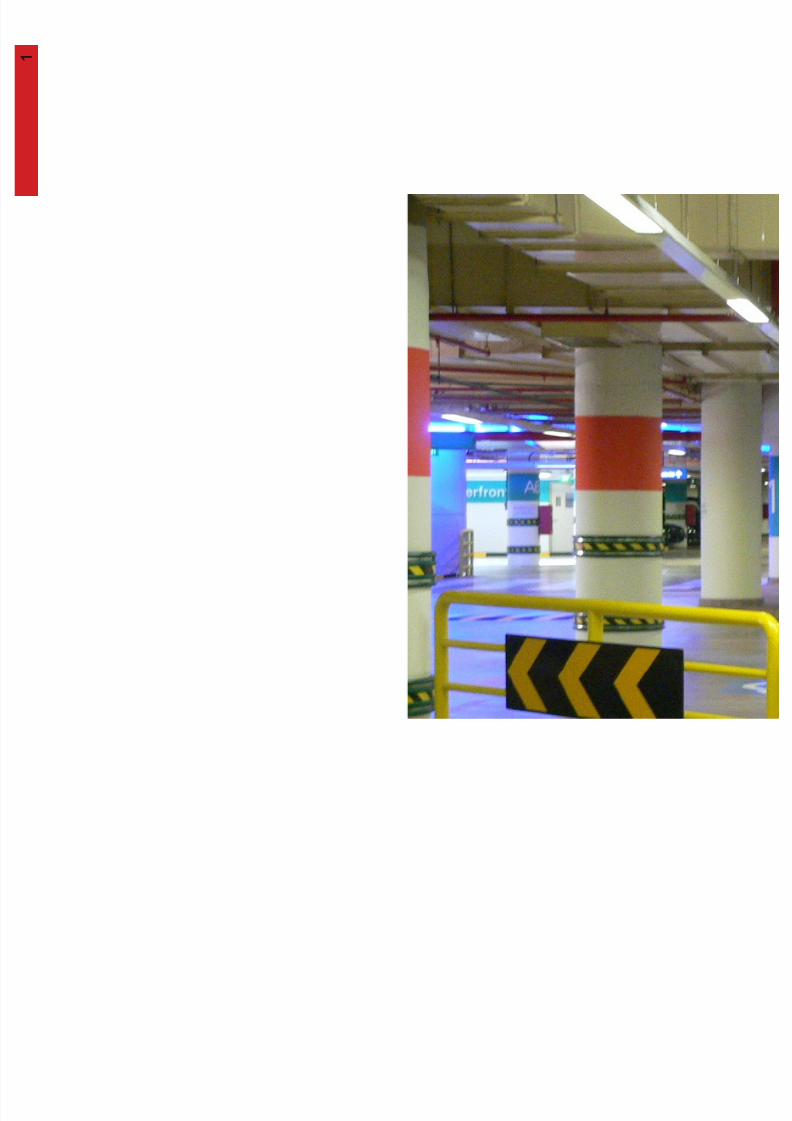
A well-designed parking space would
make the building more usable to people
of varying abilities. The convenience and
safety of drivers and their passengers
in accessing a building are thus critical
issues that must be considered in thedesign of a building.
Clear signage to lot
Provisions & Locations
Signages
Kerb Ramps
Parking lots for drivers with disabilities should be located next or
near to the carpark access lobby.Parking lots for drivers with disabilities should be located on the
same side as the access lobby, so that users need not cross the
road to reach the access lobby.
Auto signs showing number and floor of available accessible lots
should be provided.
Clear signage should be provided to indicate location of
accessible parking lots.
3
8/12/2019 Universal Design Guidelines
http://slidepdf.com/reader/full/universal-design-guidelines 19/103
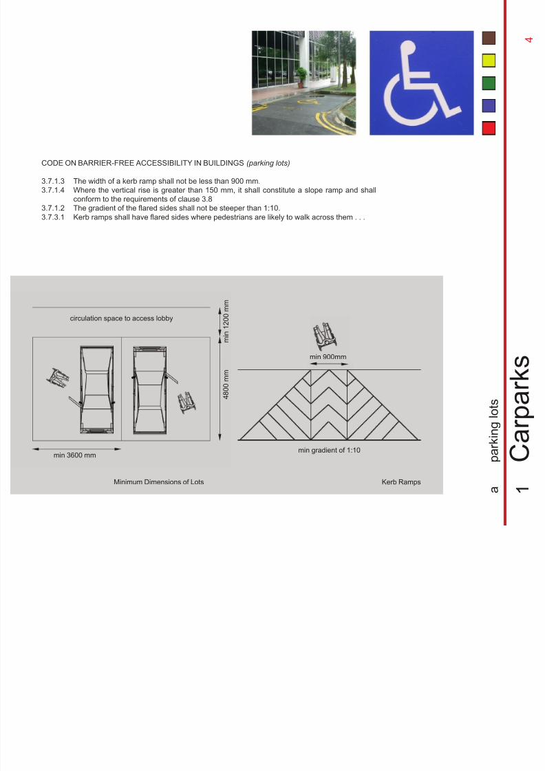
4 8 0 0 m m
min 3600 mm
Minimum Dimensions of Lots
m i n 1 2 0 0 m m
Kerb Ramps
min gradient of 1:10
circulation space to access lobby
1
C a r p a r k s
a
p a r k i n g l o t s
CODE ON BARRIER-FREE ACCESSIBILITY IN BUILDINGS (parking lots)
3.7.1.3
3.7.1.4
3.7.1.2
3.7.3.1
The width of a kerb ramp shall not be less than 900 mm.
Where the vertical rise is greater than 150 mm, it shall constitute a slope ramp and shallconform to the requirements of clause 3.8
The gradient of the flared sides shall not be steeper than 1:10.
Kerb ramps shall have flared sides where pedestrians are likely to walk across them . . .
min 900mm
4
8/12/2019 Universal Design Guidelines
http://slidepdf.com/reader/full/universal-design-guidelines 20/103
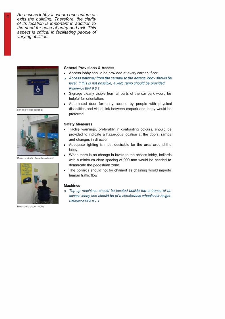
Signage to access lobby
Close proximity of machines to exit
An access lobby is where one enters orexits the building. Therefore, the clarityof its location is important in addition tothe need for ease of entry and exit. Thisaspect is critical in facilitating people ofvarying abilities.
Entrance to access lobby
General Provisions & Access
Safety Measures
Machines
Access lobby should be provided at every carpark floor.
Access pathway from the carpark to the access lobby should belevel. If this is not possible, a kerb ramp should be provided.
Reference BFA 9.6.1
Signage clearly visible from all parts of the car park would be
helpful for orientation.
Automated door for easy access by people with physical
disabilities and visual link between carpark and lobby would be
preferred.
Tactile warnings, preferably in contrasting colours, should be
provided to indicate a hazardous location at the doors, ramps
and changes in direction.
Adequate lighting is most desirable for the area around the
lobby.
When there is no change in levels to the access lobby, bollardswith a minimum clear spacing of 900 mm would be needed to
demarcate the pedestrian zone.
The bollards should not be chained as chaining would impede
human traffic flow.
Top-up machines should be located beside the entrance of an
access lobby and should be of a comfortable wheelchair height.
Reference BFA 9.7.1
5
8/12/2019 Universal Design Guidelines
http://slidepdf.com/reader/full/universal-design-guidelines 21/103
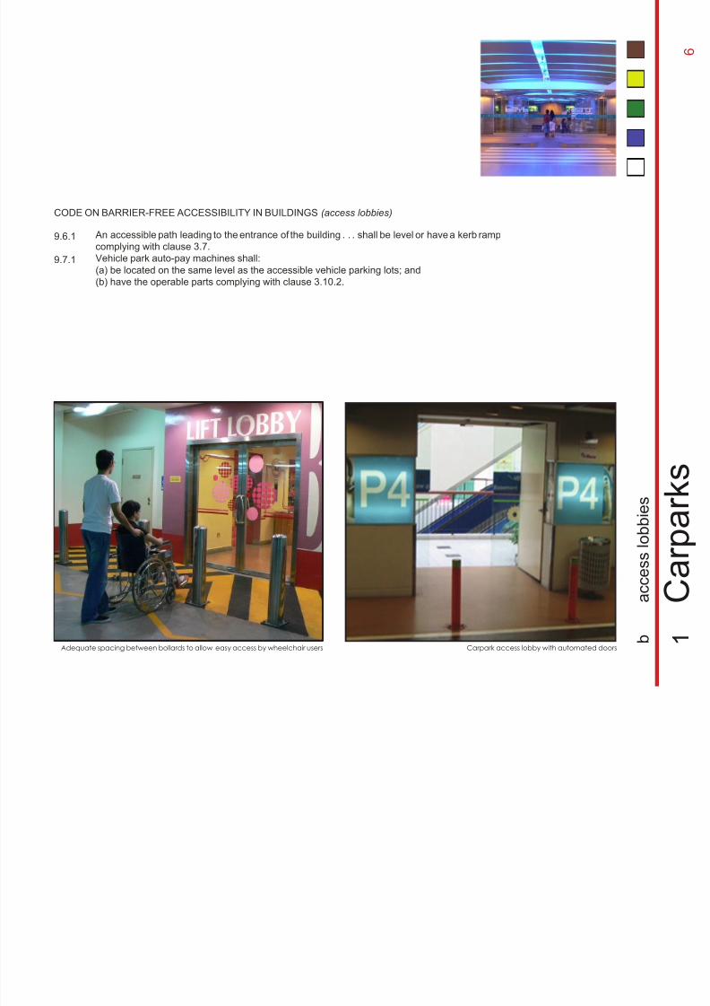
Carpark access lobby with automated doorsAdequate spacing between bollards to allow easy access by wheelchair users
CODE ON BARRIER-FREE ACCESSIBILITY IN BUILDINGS (access lobbies)
9.6.1
9.7.1
1
C a r p a r k
s
b
a c c e s s l o b b i e s
An accessible path leading to the entrance of the building . . . shall be level or have a kerb ramp
complying with clause 3.7.Vehicle park auto-pay machines shall:
(a) be located on the same level as the accessible vehicle parking lots; and
(b) have the operable parts complying with clause 3.10.2.
6
8/12/2019 Universal Design Guidelines
http://slidepdf.com/reader/full/universal-design-guidelines 22/103
7
2
E n t r a n c e s
8/12/2019 Universal Design Guidelines
http://slidepdf.com/reader/full/universal-design-guidelines 23/103
8/12/2019 Universal Design Guidelines
http://slidepdf.com/reader/full/universal-design-guidelines 24/103
seating
buffer zonemin 2 500 mm
waiting area
(buffer zone)
main driveway
inside
outside
min 3 600 mm
min 16 000 mm
drop-off zoneguardrail
bollards
lobby
2
E n t r a n c e s
9
min 900 mm clear
a
d r o p - o f f z o n e s
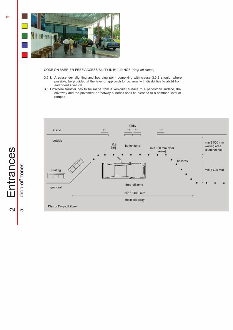
CODE ON BARRIER-FREE ACCESSIBILITY IN BUILDINGS (drop-off zones)
3.3.1.1
3.3.1.2
A passenger alighting and boarding point complying with clause 3.3.2 should, where
possible, be provided at the level of approach for persons with disabilities to alight fromand board a vehicle.
Where transfer has to be made from a vehicular surface to a pedestrian surface, the
driveway and the pavement or footway surfaces shall be blended to a common level or
ramped.
Plan of Drop-off Zone
8/12/2019 Universal Design Guidelines
http://slidepdf.com/reader/full/universal-design-guidelines 25/103
Lay-by
Finishes
Signages
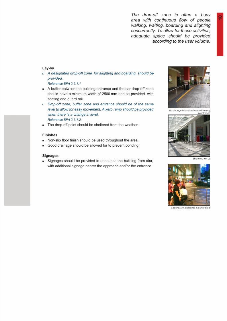
The drop-off zone is often a busy
area with continuous flow of people
walking, waiting, boarding and alighting
concurrently. To allow for these activities,
adequate space should be provided
according to the user volume.
Seating with guard rail in buffer area
No change in level between driveway& entrance
Sheltered lay-by
A designated drop-off zone, for alighting and boarding, should be
provided.Reference BFA 3.3.1.1
A buffer between the building entrance and the car drop-off zone
should have a minimum width of 2500 mm and be provided with
seating and guard rail .
Drop-off zone, buffer zone and entrance should be of the same
level to allow for easy movement. A kerb ramp should be provided
when there is a change in level.
Reference BFA 3.3.1.2
The drop-off point should be sheltered from the weather.
Non-slip floor finish should be used throughout the area.
Good drainage should be allowed for to prevent ponding.
Signages should be provided to announce the building from afar,
with additional signage nearer the approach and/or the entrance.
1 0
8/12/2019 Universal Design Guidelines
http://slidepdf.com/reader/full/universal-design-guidelines 26/103
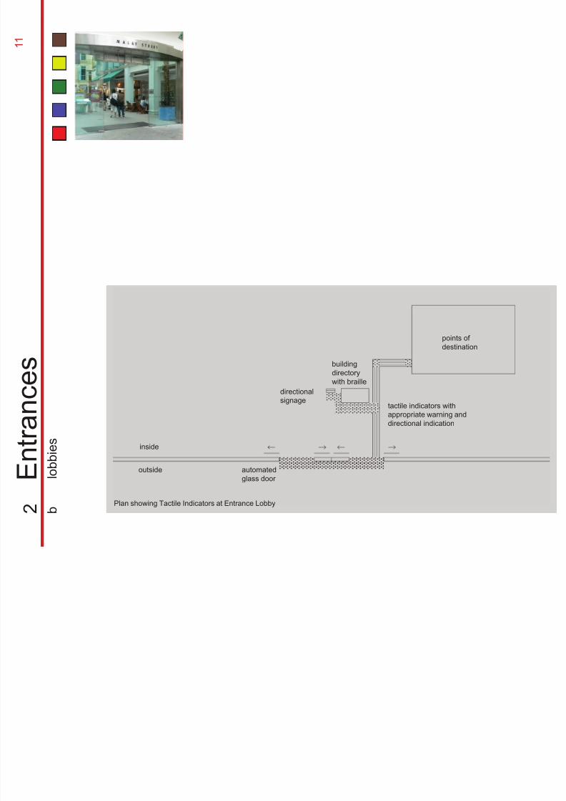
outside
inside
building
directory
with braille
tactile indicators with
appropriate warning and
directional indication
automated
glass door
points of
destination
directionalsignage
1 1
2
E n t r a n c e s
b
l o b b i e s
Plan showing Tactile Indicators at Entrance Lobby
E t i t th b ildi b i ith th
8/12/2019 Universal Design Guidelines
http://slidepdf.com/reader/full/universal-design-guidelines 27/103
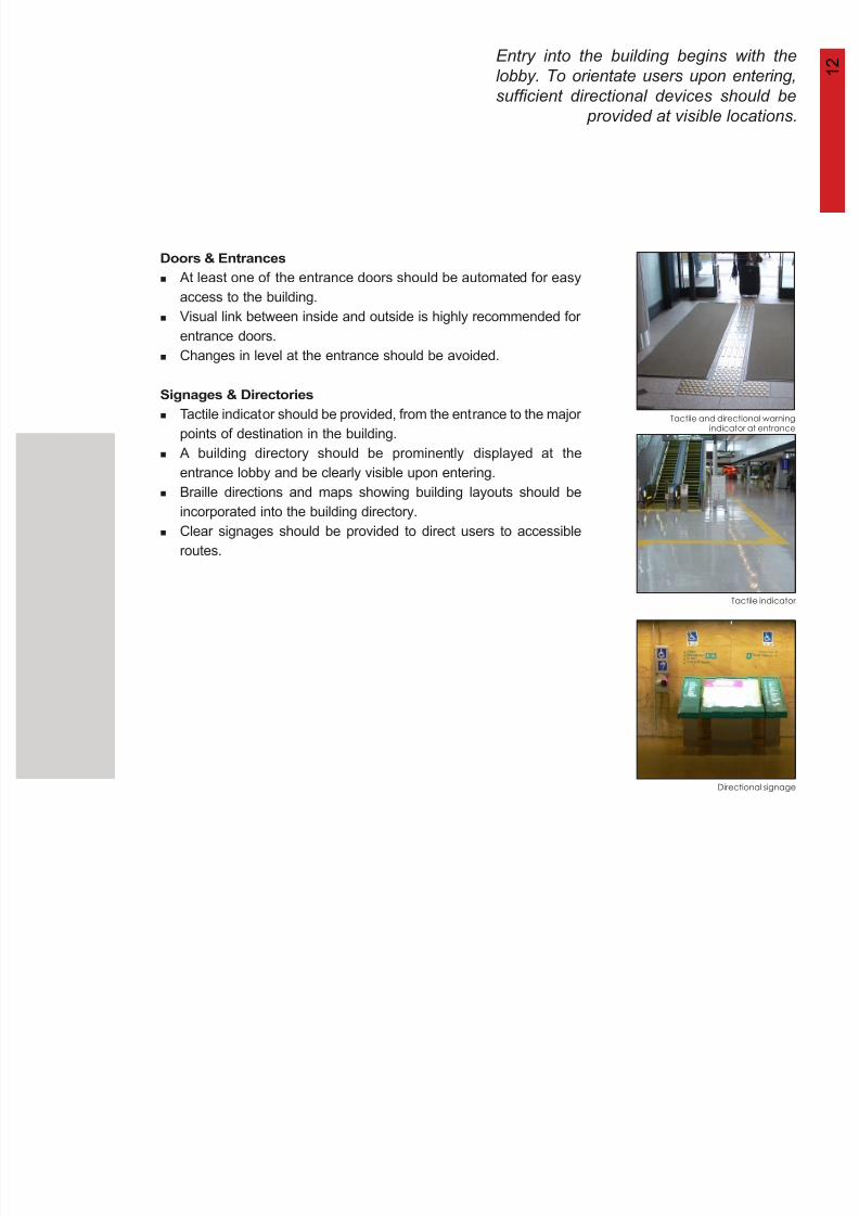
Doors & Entrances
Signages & Directories
Entry into the building begins with the
lobby. To orientate users upon entering,
sufficient directional devices should be
provided at visible locations.
Directional signage
Tactile and directional warningindicator at entrance
Tactile indicator
At least one of the entrance doors should be automated for easy
access to the building.Visual link between inside and outside is highly recommended for
entrance doors.
Changes in level at the entrance should be avoided.
Tactile indicator should be provided, from the entrance to the major
points of destination in the building.
A building directory should be prominently displayed at the
entrance lobby and be clearly visible upon entering.
Braille directions and maps showing building layouts should be
incorporated into the building directory.
Clear signages should be provided to direct users to accessible
routes.
1 2
8/12/2019 Universal Design Guidelines
http://slidepdf.com/reader/full/universal-design-guidelines 28/103
1 3
8/12/2019 Universal Design Guidelines
http://slidepdf.com/reader/full/universal-design-guidelines 29/103
3
H o r i z o n t a l C i r c u
l a t i o n
1 4
In the design of corridors it is important
8/12/2019 Universal Design Guidelines
http://slidepdf.com/reader/full/universal-design-guidelines 30/103
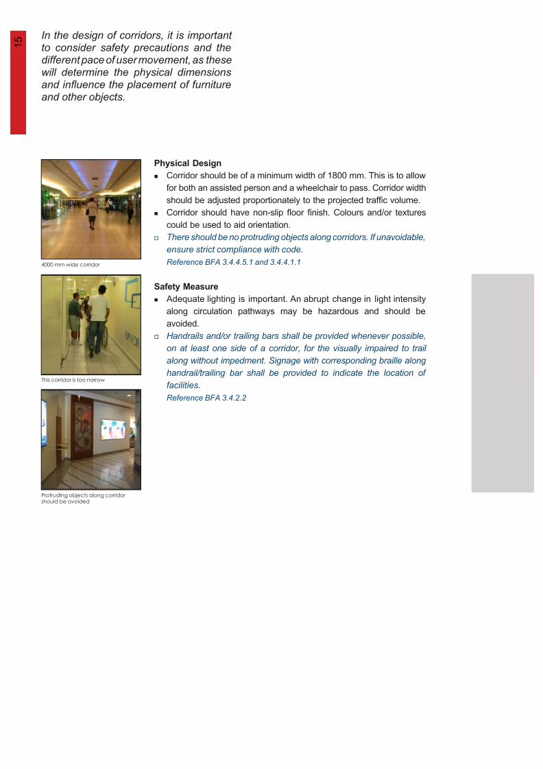
In the design of corridors, it is importantto consider safety precautions and thedifferent pace of user movement, as thesewill determine the physical dimensionsand influence the placement of furniture
and other objects.
4000 mm wide corridor
Protruding objects along corridorshould be avoided
This corridor is too narrow
Physical Design
Safety Measure
Corridor should be of a minimum width of 1800 mm. This is to allow
for both an assisted person and a wheelchair to pass. Corridor widthshould be adjusted proportionately to the projected traffic volume.
Corridor should have non-slip floor finish. Colours and/or textures
could be used to aid orientation.
There should be no protruding objects along corridors. If unavoidable,
ensure strict compliance with code.
Reference BFA 3.4.4.5.1 and 3.4.4.1.1
Adequate lighting is important. An abrupt change in light intensity
along circulation pathways may be hazardous and should be
avoided.
Handrails and/or trailing bars shall be provided whenever possible,
on at least one side of a corridor, for the visually impaired to trail
along without impedment. Signage with corresponding braille along
handrail/trailing bar shall be provided to indicate the location offacilities.
Reference BFA 3.4.2.2
1 5
6
8/12/2019 Universal Design Guidelines
http://slidepdf.com/reader/full/universal-design-guidelines 31/103
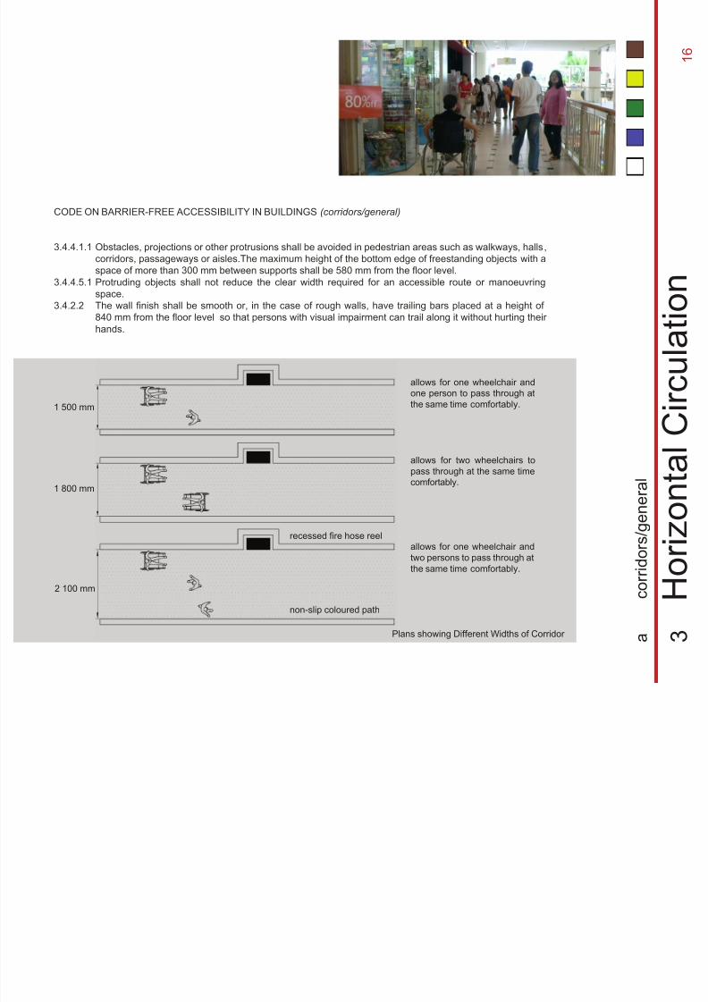
2 100 mm
non-slip coloured path
1 800 mm
1 500 mm
recessed fire hose reelallows for one wheelchair and
two persons to pass through at
the same time comfortably.
CODE ON BARRIER-FREE ACCESSIBILITY IN BUILDINGS (corridors/general)
3.4.4.1.1
3.4.4.5.1
3.4.2.2
Obstacles, projections or other protrusions shall be avoided in pedestrian areas such as walkways, halls,corridors, passageways or aisles.The maximum height of the bottom edge of freestanding objects with a
space of more than 300 mm between supports shall be 580 mm from the floor level.
Protruding objects shall not reduce the clear width required for an accessible route or manoeuvring
space.
The wall finish shall be smooth or, in the case of rough walls, have trailing bars placed at a height of
840 mm from the floor level so that persons with visual impairment can trail along it without hurting their
hands.
Plans showing Different Widths of Corridor 3
H o r i z o n t a l C i r c u
l a t i o n
a
c o r r i d o r s / g e n e r a
l
allows for one wheelchair and
one person to pass through at
the same time comfortably.
allows for two wheelchairs to
pass through at the same time
comfortably.
1 6
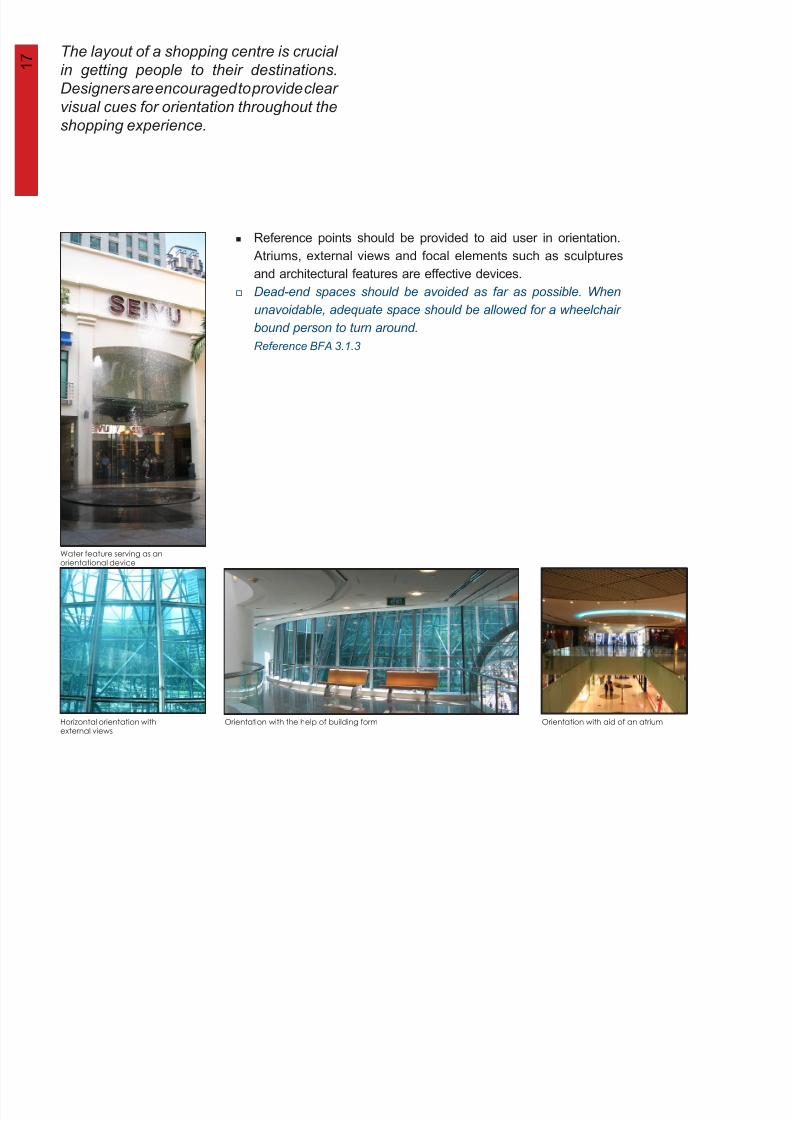
7 The layout of a shopping centre is crucial
8/12/2019 Universal Design Guidelines
http://slidepdf.com/reader/full/universal-design-guidelines 32/103
1 7 y pp g
in getting people to their destinations.
Designers are encouraged to provide clear
visual cues for orientation throughout the
shopping experience.
Horizontal orientation withexternal views
Orientation with the help of building form Orientation with aid of an atrium
Water feature serving as anorientational device
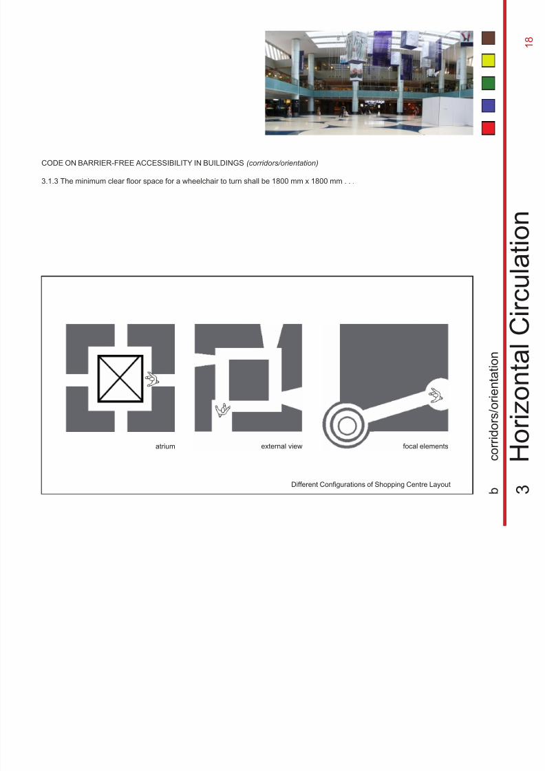
Reference points should be provided to aid user in orientation.
Atriums, external views and focal elements such as sculptures
and architectural features are effective devices.Dead-end spaces should be avoided as far as possible. When
unavoidable, adequate space should be allowed for a wheelchair
bound person to turn around.
Reference BFA 3.1.3
8
8/12/2019 Universal Design Guidelines
http://slidepdf.com/reader/full/universal-design-guidelines 33/103
CODE ON BARRIER-FREE ACCESSIBILITY IN BUILDINGS (corridors/orientation)
3.1.3 The minimum clear floor space for a wheelchair to turn shall be 1800 mm x 1800 mm . . .
3
H o r i z o n
t a l C i r c u
l a t i o n
b
c o r r i d o r s / o r i e n t a
t i o n
external view
Different Configurations of Shopping Centre Layout
focal elementsatrium
1 8
Apart from ease of accessibility,9
8/12/2019 Universal Design Guidelines
http://slidepdf.com/reader/full/universal-design-guidelines 34/103
comfort of the users travelling along the
circulation path should also be taken into
design consideration.
Seating along a corridor
Seating within a wide corridor
Seating around pillar
seating along corridor
at intervals, without
interfering the
circulation space.
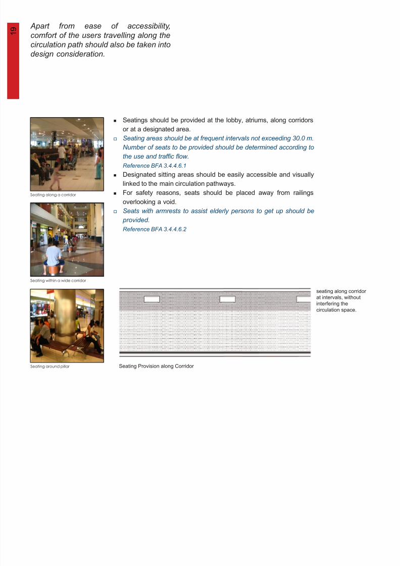
Seatings should be provided at the lobby, atriums, along corridors
or at a designated area.
Seating areas should be at frequent intervals not exceeding 30.0 m.Number of seats to be provided should be determined according to
the use and traffic flow.
Reference BFA 3.4.4.6.1
Designated sitting areas should be easily accessible and visually
linked to the main circulation pathways.
For safety reasons, seats should be placed away from railings
overlooking a void.
Seats with armrests to assist elderly persons to get up should be
provided.
Reference BFA 3.4.4.6.2
Seating Provision along Corridor
1
2 0
8/12/2019 Universal Design Guidelines
http://slidepdf.com/reader/full/universal-design-guidelines 35/103
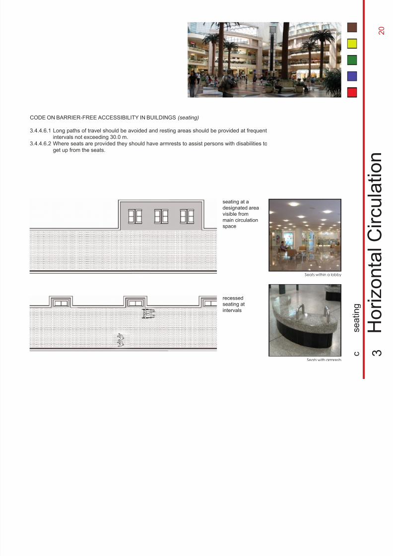
seating at a
designated area
visible from
main circulation
space
Seats with armrests
Seats within a lobby
CODE ON BARRIER-FREE ACCESSIBILITY IN BUILDINGS (seating)
3.4.4.6.1
3.4.4.6.2
Long paths of travel should be avoided and resting areas should be provided at frequent
intervals not exceeding 30.0 m.Where seats are provided they should have armrests to assist persons with disabilities to
get up from the seats.
recessed
seating at
intervals
3
H o r i z o n
t a l C i r c u
l a t i o n
c
s e a t i n g
2
2 1
8/12/2019 Universal Design Guidelines
http://slidepdf.com/reader/full/universal-design-guidelines 36/103
2
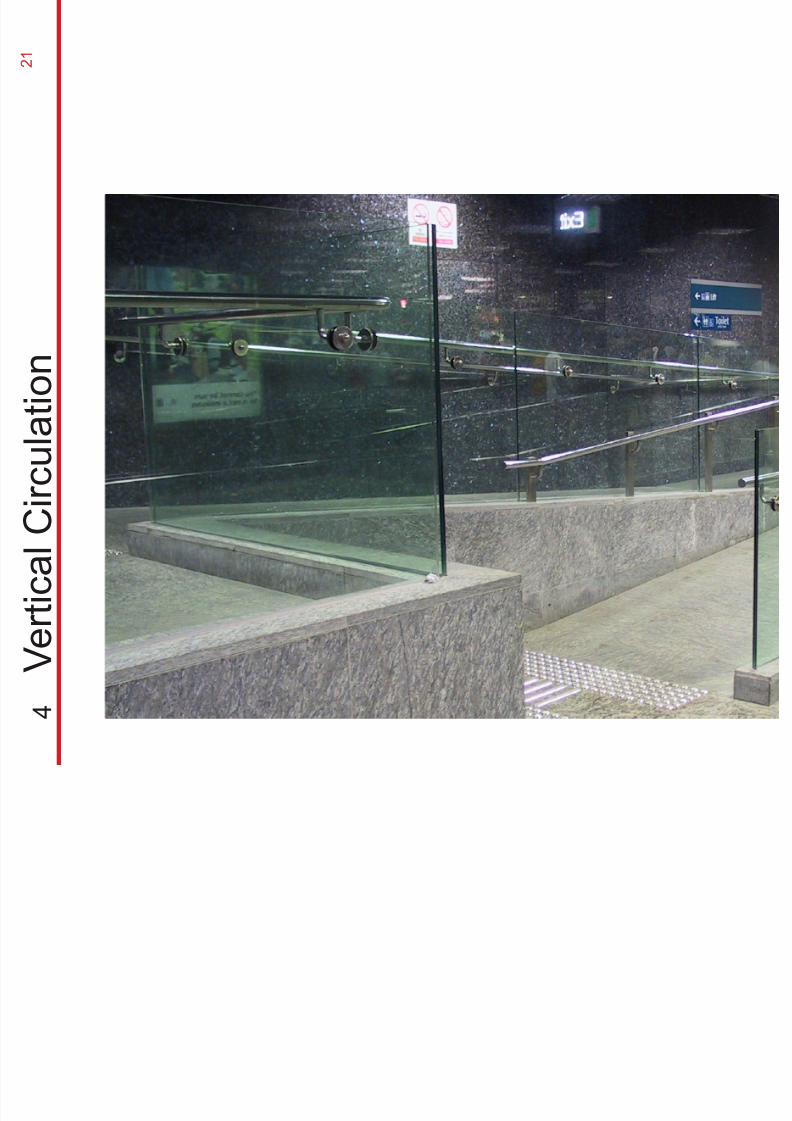
4
V e r t i c a l C i r c u l a t
i o n
2 2
8/12/2019 Universal Design Guidelines
http://slidepdf.com/reader/full/universal-design-guidelines 37/103
2
2 3
8/12/2019 Universal Design Guidelines
http://slidepdf.com/reader/full/universal-design-guidelines 38/103
2
Corridor
Landing
2000min
max 580 mm
tactile
markings
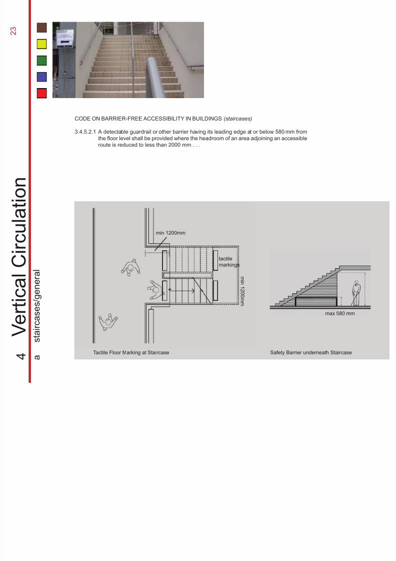
CODE ON BARRIER-FREE ACCESSIBILITY IN BUILDINGS (staircases)
3.4.5.2.1
4
V e r t i c a l C i r c u l a t
i o n
a
s
t a i r c a s e s / g e n e r a
l
A detectable guardrail or other barrier having its leading edge at or below 580 mm from
the floor level shall be provided where the headroom of an area adjoining an accessibleroute is reduced to less than 2000 mm . . .
Tactile Floor Marking at Staircase Safety Barrier underneath Staircase
mi n1 2 0 0 mm
min 1200mm
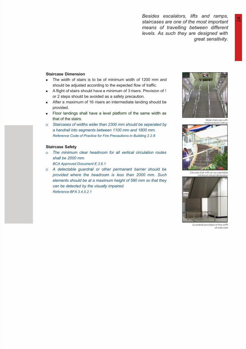
Besides escalators, lifts and ramps,
staircases are one of the most important 2 4
8/12/2019 Universal Design Guidelines
http://slidepdf.com/reader/full/universal-design-guidelines 39/103
staircases are one of the most important
means of travelling between different
levels. As such they are designed with
great sensitivity.
Wide staircase withintermediate railings
Circular stair with an acceptableminimum tread dimension
Guardrail provided at the soffit
of staircase
Staircase Dimension
Staircase Safety
The width of stairs is to be of minimum width of 1200 mm and
should be adjusted according to the expected flow of traffic.
A flight of stairs should have a minimum of 3 risers. Provision of 1
or 2 steps should be avoided as a safety precaution.
After a maximum of 16 risers an intermediate landing should be
provided.
Floor landings shall have a level platform of the same width as
that of the stairs.
Staircases of widths wider than 2300 mm should be seperated by
a handrail into segments between 1100 mm and 1800 mm.
Reference Code of Practice for Fire Precautions in Building 2.2.8
The minimum clear headroom for all vertical circulation routes
shall be 2000 mm.
BCA Approved Document E.3.6.1
A detectable guardrail or other permanent barrier should be provided where the headroom is less than 2000 mm. Such
elements should be at a maximum height of 580 mm so that they
can be detected by the visually impaired.
Reference BFA 3.4.5.2.1
2 5
8/12/2019 Universal Design Guidelines
http://slidepdf.com/reader/full/universal-design-guidelines 40/103
4
V e r t i c a l C i r c u l a t i o n
a
s t a i r c a s e s / t r e a d s & r i s e r s
warning
treatment
max 150 mm
max 25 mm
min 300 mm
depth
of tread
min 600 mm
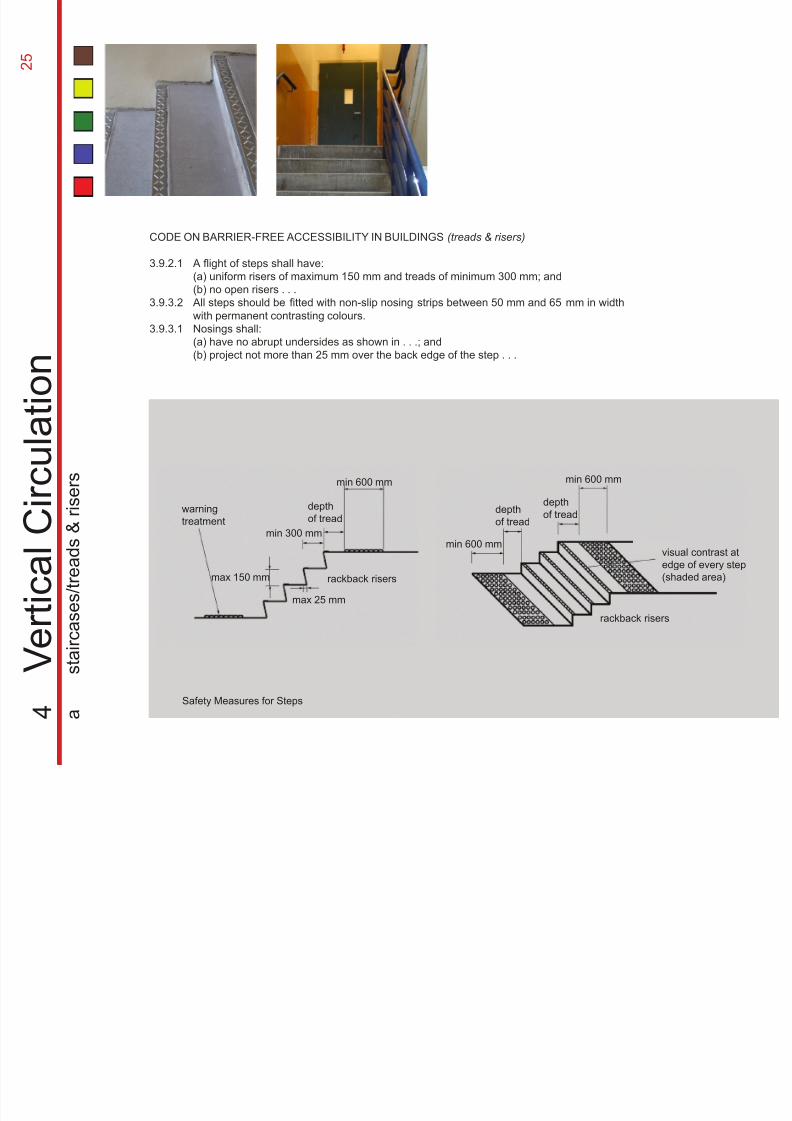
CODE ON BARRIER-FREE ACCESSIBILITY IN BUILDINGS (treads & risers)
3.9.2.1
3.9.3.2
3.9.3.1
A flight of steps shall have:
(a) uniform risers of maximum 150 mm and treads of minimum 300 mm; and(b) no open risers . . .
All steps should be fitted with non-slip nosing strips between 50 mm and 65 mm in width
with permanent contrasting colours.
Nosings shall:
(a) have no abrupt undersides as shown in . . .; and
(b) project not more than 25 mm over the back edge of the step . . .
depth
of tread
min 600 mm
min 600 mmvisual contrast atedge of every step
(shaded area)
depth
of tread
rackback risers
rackback risers
Safety Measures for Steps
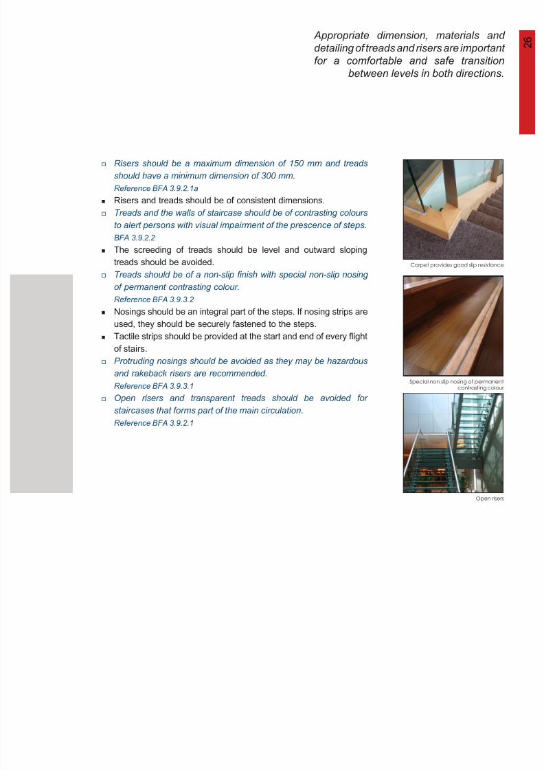
2 6 Appropriate dimension, materials and
detailing of treads and risers are important
8/12/2019 Universal Design Guidelines
http://slidepdf.com/reader/full/universal-design-guidelines 41/103
g p
for a comfortable and safe transition
between levels in both directions.
Carpet provides good slip resistance
Special non slip nosing of permanentcontrasting colour
Open risers
Risers should be a maximum dimension of 150 mm and treads
should have a minimum dimension of 300 mm.
Reference BFA 3.9.2.1a
Risers and treads should be of consistent dimensions.
Treads and the walls of staircase should be of contrasting colours
to alert persons with visual impairment of the prescence of steps.
BFA 3.9.2.2
The screeding of treads should be level and outward sloping
treads should be avoided.
Treads should be of a non-slip finish with special non-slip nosing
of permanent contrasting colour.Reference BFA 3.9.3.2
Nosings should be an integral part of the steps. If nosing strips are
used, they should be securely fastened to the steps.
Tactile strips should be provided at the start and end of every flight
of stairs.
Protruding nosings should be avoided as they may be hazardous
and rakeback risers are recommended.Reference BFA 3.9.3.1
Open risers and transparent treads should be avoided for
staircases that forms part of the main circulation.
Reference BFA 3.9.2.1
2 7
8/12/2019 Universal Design Guidelines
http://slidepdf.com/reader/full/universal-design-guidelines 42/103
min 300 mm
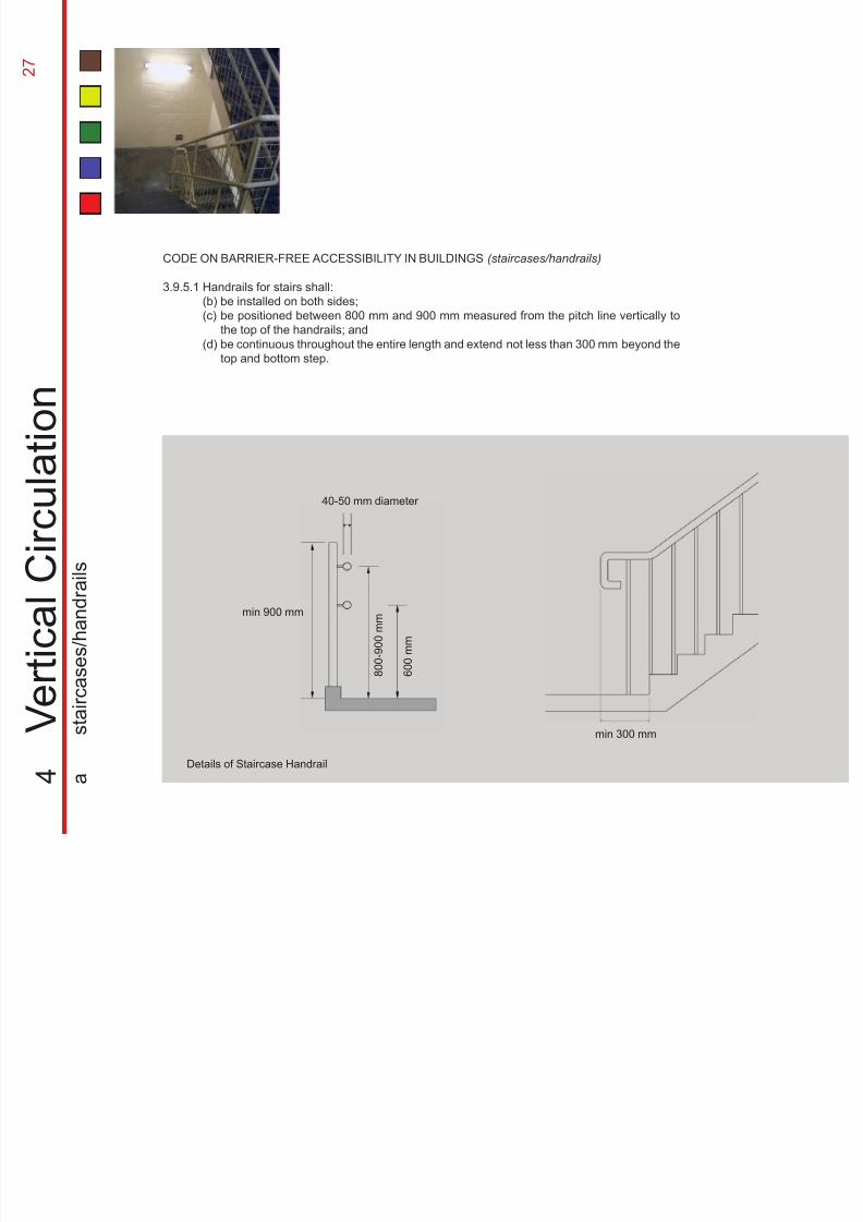
CODE ON BARRIER-FREE ACCESSIBILITY IN BUILDINGS (staircases/handrails)
3.9.5.1
4
V e r t i c a l C i r c u l a t i o n
a
s t a i r c a s e s / h a n d r a i l s
Handrails for stairs shall:
(b)(c)
(d)
be installed on both sides;be positioned between 800 mm and 900 mm measured from the pitch line vertically to
the top of the handrails; and
be continuous throughout the entire length and extend not less than 300 mm beyond the
top and bottom step.
40-50 mm diameter
6 0 0 m m
8 0 0 - 9 0 0 m m
min 900 mm
Details of Staircase Handrail
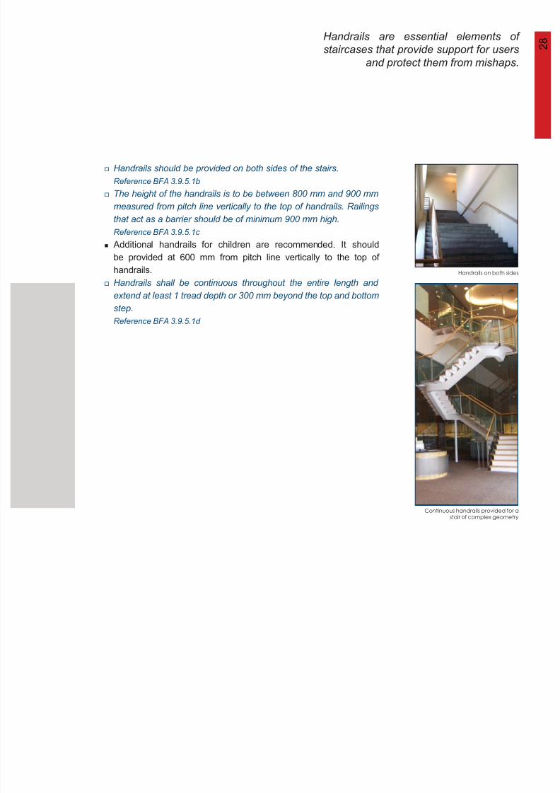
Handrails are essential elements of
staircases that provide support for users 2 8
8/12/2019 Universal Design Guidelines
http://slidepdf.com/reader/full/universal-design-guidelines 43/103
and protect them from mishaps.
Handrails on both sides
Continuous handrails provided for astair of complex geometry
Handrails should be provided on both sides of the stairs.
Reference BFA 3.9.5.1b
The height of the handrails is to be between 800 mm and 900 mm
measured from pitch line vertically to the top of handrails. Railings
that act as a barrier should be of minimum 900 mm high.
Reference BFA 3.9.5.1c
Additional handrails for children are recommended. It should
be provided at 600 mm from pitch line vertically to the top of
handrails.
Handrails shall be continuous throughout the entire length and
extend at least 1 tread depth or 300 mm beyond the top and bottomstep.
Reference BFA 3.9.5.1d
2 9
8/12/2019 Universal Design Guidelines
http://slidepdf.com/reader/full/universal-design-guidelines 44/103
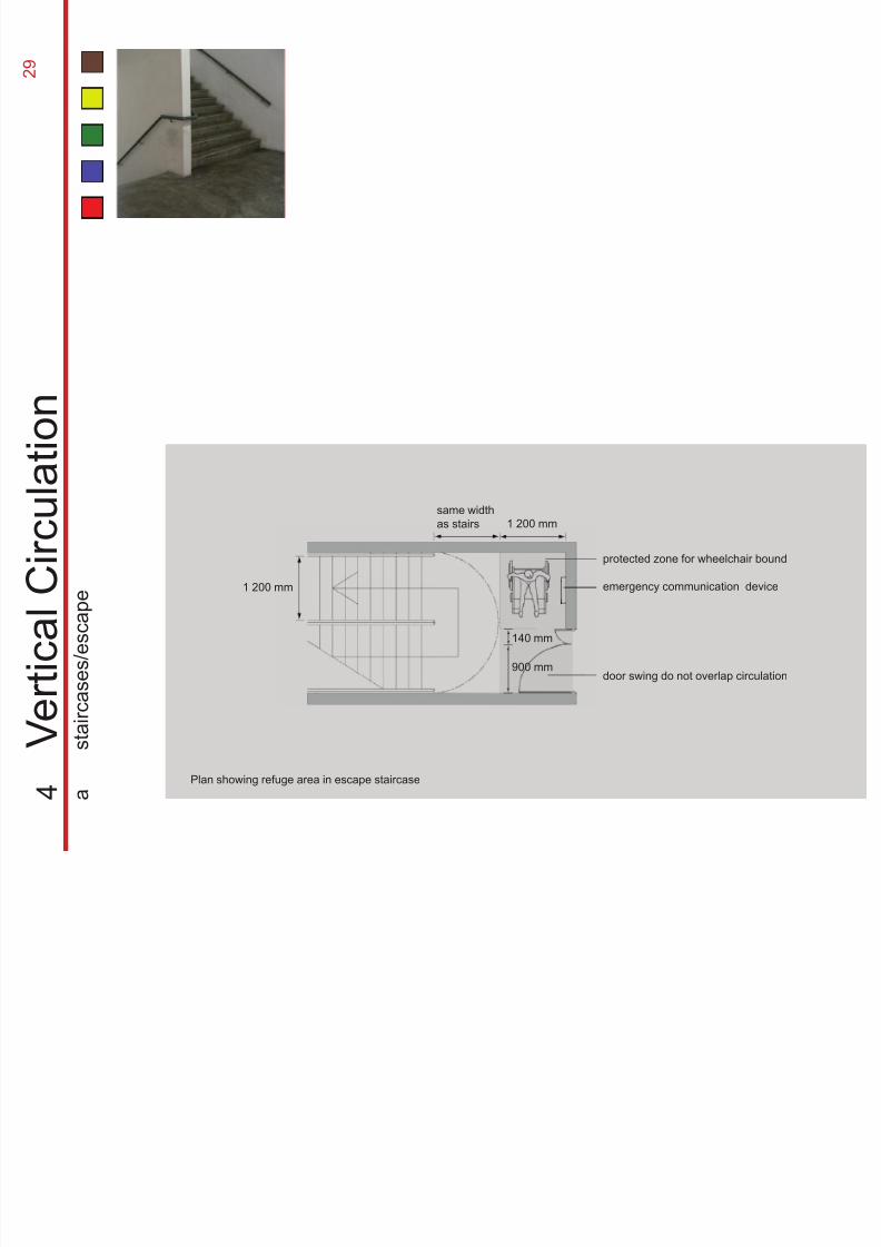
Plan showing refuge area in escape staircase
protected zone for wheelchair bound
emergency communication device
door swing do not overlap circulation
1 200 mm
1 200 mm
same width
as stairs
140 mm
900 mm
4
V e r t i c a l C i r c u l a t i o n
a
s t a i r c a s e s / e s c a p e
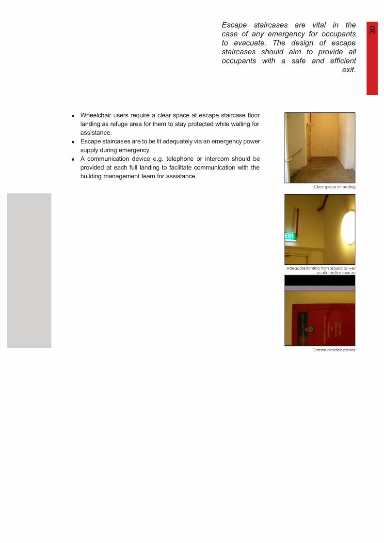
3 0Escape staircases are vital in the
case of any emergency for occupants
t t Th d i f
8/12/2019 Universal Design Guidelines
http://slidepdf.com/reader/full/universal-design-guidelines 45/103
to evacuate. The design of escape
staircases should aim to provide all
occupants with a safe and efficient
exit.
Clear space at landing
Communication device
Adequate lighting from regular as wellas alternative sources
Wheelchair users require a clear space at escape staircase floor
landing as refuge area for them to stay protected while waiting for
assistance.
Escape staircases are to be lit adequately via an emergency power
supply during emergency.
A communication device e.g. telephone or intercom should be
provided at each full landing to facilitate communication with the
building management team for assistance.
3 1
8/12/2019 Universal Design Guidelines
http://slidepdf.com/reader/full/universal-design-guidelines 46/103
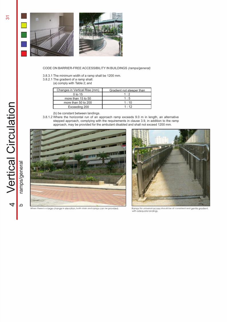
When there is a large change in elevation, both stairs and ramps can be provided. Ramps for universal access should be of consistent and gentle gradient,with adequate landings.
CODE ON BARRIER-FREE ACCESSIBILITY IN BUILDINGS (ramps/general)
3.8.3.1
3.8.2.1
3.8.1.2
4
V e r t i c a l C i r c u l a t i o n
b
r a m p s / g e n e r a l
The minimum width of a ramp shall be 1200 mm.
The gradient of a ramp shall:
(a) comply with Table 2; and
(b) be constant between landings.
Where the horizontal run of an approach ramp exceeds 9.0 m in length, an alternative
stepped approach, complying with the requirements in clause 3.9, in addition to the rampapproach, may be provided for the ambulant disabled and shall not exceed 1200 mm.
Changes in Vertical Rise (mm)
0 to 15
more than 15 to 50
more than 50 to 200
Exceeding 200
Gradient not steeper than
1 : 2
1 : 5
1 : 10
1 : 12
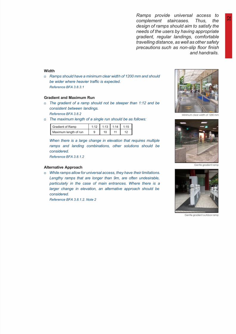
Ramps provide universal access tocomplement staircases. Thus, thedesign of ramps should aim to satisfy the
3 2
8/12/2019 Universal Design Guidelines
http://slidepdf.com/reader/full/universal-design-guidelines 47/103
Width
Gradient and Maximum Run
Alternative Approach
Ramps should have a minimum clear width of 1200 mm and should
be wider where heavier traffic is expected.
Reference BFA 3.8.3.1
The gradient of a ramp should not be steeper than 1:12 and be
consistent between landings.
Reference BFA 3.8.2
The maximum length of a single run should be as follows:
When there is a large change in elevation that requires multiple
ramps and landing combinations, other solutions should be
considered.
Reference BFA 3.8.1.2
While ramps allow for universal access, they have their limitations.
Lengthy ramps that are longer than 9m, are often undesirable,
particularly in the case of main entrances. Where there is a
larger change in elevation, an alternative approach should be
considered.
Reference BFA 3.8.1.2. Note 2
design of ramps should aim to satisfy theneeds of the users by having appropriategradient, regular landings, comfortable
travelling distance, as well as other safety precautions such as non-slip floor finishand handrails.
Gentle gradient ramp
Minimum clear width of 1200 mm
Gradient of Ramp 1:12 1:13 1:14 1:15
Maximum length of run 9 10 11 12
Gentle gradient outdoor ramp
3 3
8/12/2019 Universal Design Guidelines
http://slidepdf.com/reader/full/universal-design-guidelines 48/103
recommended2 000 mm
1 200 mm
1 500 mm
1 500 mm x
1 500 mm
1 500 mm
1 200 mm
1 500 mm
2 500 mm
1 200 mm
1 200 mm
1 500 mm
2 500
mm
2 500 mm
1 200 mm
1 200 mm
1 500 mm
2 000 mm
1 500 mm x
1 500 mm
500 mm
2 000 mm x
2 000 mm
1 500 mm
1 200 mm
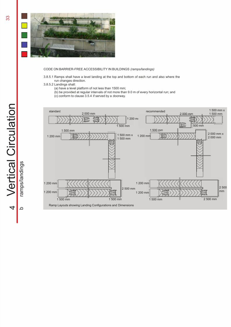
CODE ON BARRIER-FREE ACCESSIBILITY IN BUILDINGS (ramps/landings)
3.8.5.1
3.8.5.2
4
V e r t i c a l C i r c u l a t i o n
b
r a m p s / l a n d i n g s
Ramps shall have a level landing at the top and bottom of each run and also where the
run changes direction.
Landings shall:
(a) have a level platform of not less than 1500 mm;
(b) be provided at regular intervals of not more than 9.0 m of every horizontal run; and
(c) conform to clause 3.5.4 if served by a doorway.
standard
Ramp Layouts showing Landing Configurations and Dimensions
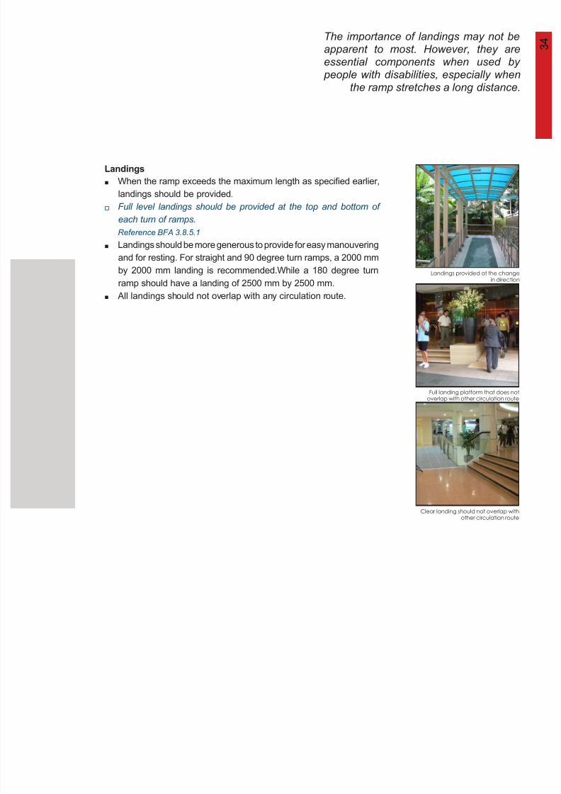
The importance of landings may not beapparent to most. However, they areessential components when used by
3 4
8/12/2019 Universal Design Guidelines
http://slidepdf.com/reader/full/universal-design-guidelines 49/103
Landings
Clear landing should not overlap withother circulation route
essential components when used by people with disabilities, especially when
the ramp stretches a long distance.
Landings provided at the changein direction
Full landing platform that does notoverlap with other circulation route
When the ramp exceeds the maximum length as specified earlier,
landings should be provided.
Full level landings should be provided at the top and bottom of
each turn of ramps.
Reference BFA 3.8.5.1
Landings should be more generous to provide for easy manouvering
and for resting. For straight and 90 degree turn ramps, a 2000 mm
by 2000 mm landing is recommended.While a 180 degree turn
ramp should have a landing of 2500 mm by 2500 mm.
All landings should not overlap with any circulation route.
3 5
8/12/2019 Universal Design Guidelines
http://slidepdf.com/reader/full/universal-design-guidelines 50/103
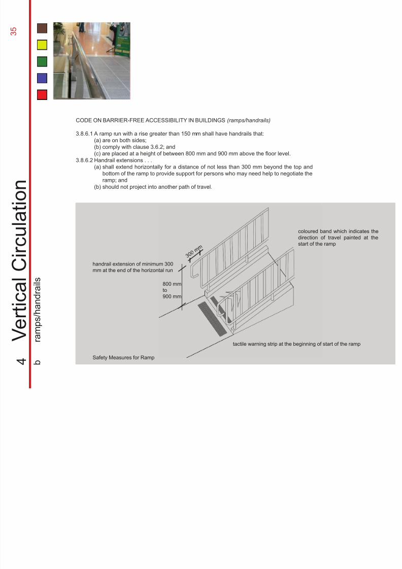
CODE ON BARRIER-FREE ACCESSIBILITY IN BUILDINGS (ramps/handrails)
3.8.6.1
3.8.6.2
handrail extension of minimum 300
mm at the end of the horizontal run
3 0 0 m m
tactile warning strip at the beginning of start of the ramp
coloured band which indicates the
direction of travel painted at the
start of the ramp
A ramp run with a rise greater than 150 mm shall have handrails that:
(a) are on both sides;
(b) comply with clause 3.6.2; and
(c) are placed at a height of between 800 mm and 900 mm above the floor level.
Handrail extensions . . .
(a)
(b)
4
V e r t i c a l C i r c u l a t i o n
b
r a m p s / h a n d r a i l s
shall extend horizontally for a distance of not less than 300 mm beyond the top and
bottom of the ramp to provide support for persons who may need help to negotiate the
ramp; and
should not project into another path of travel.
Safety Measures for Ramp
800 mm
to
900 mm
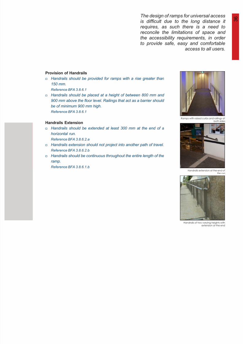
The design of ramps for universal accessis difficult due to the long distance itrequires, as such there is a need to
3 6
8/12/2019 Universal Design Guidelines
http://slidepdf.com/reader/full/universal-design-guidelines 51/103
q ,reconcile the limitations of space andthe accessibility requirements, in orderto provide safe, easy and comfortable
access to all users.
Provision of Handrails
Handrails Extension
Ramps with raised curbs and railings atboth sides
Handrails extension at the end ofthe run
Handrails of two varying heights withextension at the end
Handrails should be provided for ramps with a rise greater than
150 mm.
Reference BFA 3.8.6.1
Handrails should be placed at a height of between 800 mm and
900 mm above the floor level. Railings that act as a barrier should
be of minimum 900 mm high.
Reference BFA 3.8.6.1
Handrails should be extended at least 300 mm at the end of ahorizontal run.
Reference BFA 3.8.6.2.a
Handrails extension should not project into another path of travel.
Reference BFA 3.8.6.2.b
Handrails should be continuous throughout the entire length of the
ramp.
Reference BFA 3.8.6.1.b
3 7
8/12/2019 Universal Design Guidelines
http://slidepdf.com/reader/full/universal-design-guidelines 52/103
Kerb with a Minimum Height of
75 mm
Raised Barrier with its Lower
Edge not more than 75 mm
800 mm 900 mm
75 mm
50 mm45 mm
t o a l i g n w i t h h a n d r a i l
75 mm
800 mm 900 mm
50 mm45 mm
t o a l i g n w i t h h a n d r a i l
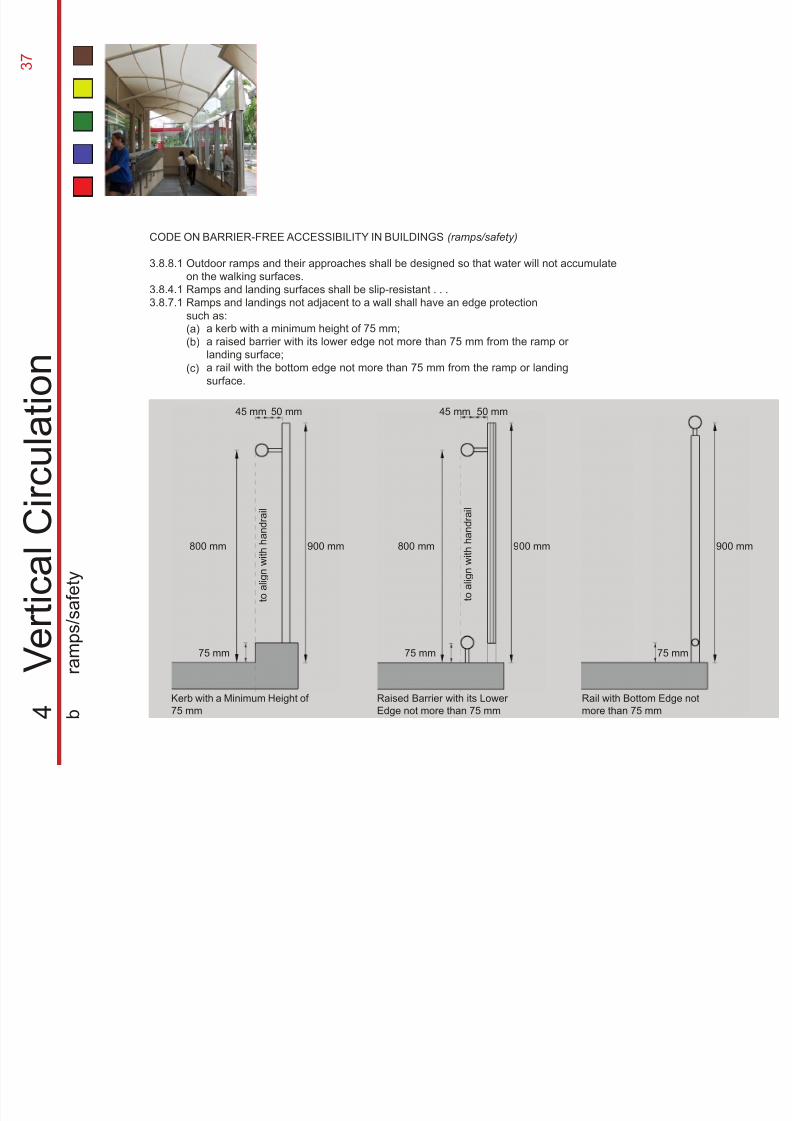
CODE ON BARRIER-FREE ACCESSIBILITY IN BUILDINGS (ramps/safety)
3.8.8.1
3.8.4.13.8.7.1
4
V e r t i c a l
C i r c u l a t i o n
b
r a m p s / s a f e t y
Outdoor ramps and their approaches shall be designed so that water will not accumulate
on the walking surfaces.
Ramps and landing surfaces shall be slip-resistant . . .Ramps and landings not adjacent to a wall shall have an edge protection
such as:
(a)
(b)
(c)
75 mm
900 mm
Rail with Bottom Edge not
more than 75 mm
a kerb with a minimum height of 75 mm;
a raised barrier with its lower edge not more than 75 mm from the ramp or
landing surface;
a rail with the bottom edge not more than 75 mm from the ramp or landing
surface.
To provide universal access to all users,ramps should be designed as an integral part of the circulation of a building, so
3 8
8/12/2019 Universal Design Guidelines
http://slidepdf.com/reader/full/universal-design-guidelines 53/103
as to ensure the smooth flow of humantraffic and to provide a safe and protected
access.
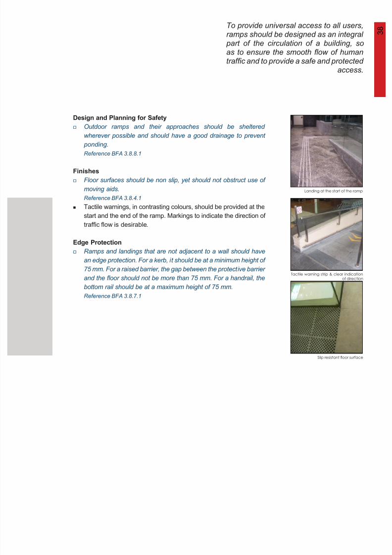
Design and Planning for Safety
Finishes
Edge Protection
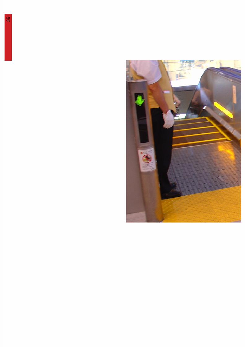
Tactile warning strip & clear indicationof direction
Slip resistant floor surface
Landing at the start of the ramp
Outdoor ramps and their approaches should be sheltered
wherever possible and should have a good drainage to prevent
ponding.
Reference BFA 3.8.8.1
Floor surfaces should be non slip, yet should not obstruct use of
moving aids.
Reference BFA 3.8.4.1
Tactile warnings, in contrasting colours, should be provided at thestart and the end of the ramp. Markings to indicate the direction of
traffic flow is desirable.
Ramps and landings that are not adjacent to a wall should have
an edge protection. For a kerb, it should be at a minimum height of
75 mm. For a raised barrier, the gap between the protective barrier
and the floor should not be more than 75 mm. For a handrail, the
bottom rail should be at a maximum height of 75 mm.
Reference BFA 3.8.7.1
3 9
8/12/2019 Universal Design Guidelines
http://slidepdf.com/reader/full/universal-design-guidelines 54/103
4 0
8/12/2019 Universal Design Guidelines
http://slidepdf.com/reader/full/universal-design-guidelines 55/103
4
M e c h a n
i c a l C i r c u l a t i o n
4 1 Lifts are the most common form of vertical
transportation and are an integral part of
the accessible route. As such, attention
should be paid to the design in order to
8/12/2019 Universal Design Guidelines
http://slidepdf.com/reader/full/universal-design-guidelines 56/103
should be paid to the design in order to
accommodate the needs of people with
different abilities.
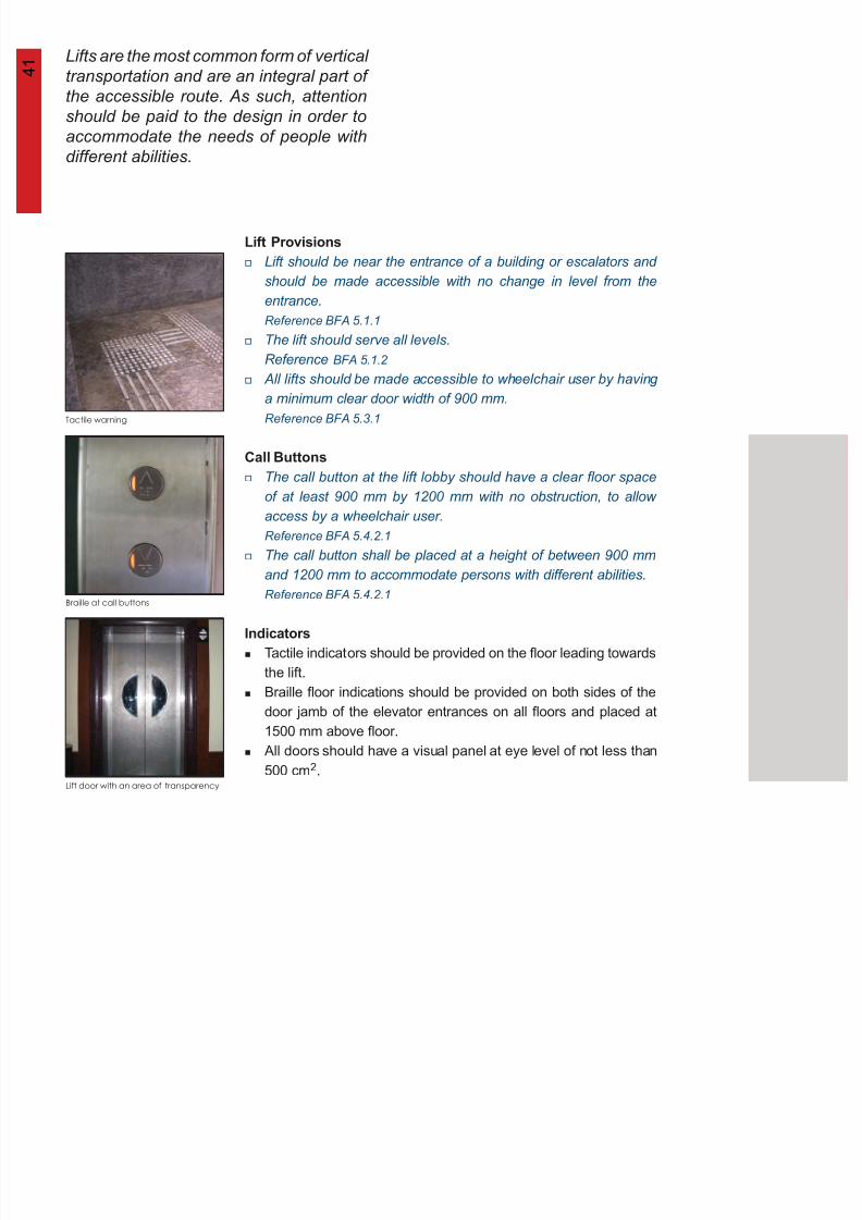
Tactile warning
Braille at call buttons
Lift door with an area of transparency
Lift Provisions
Call Buttons
Indicators
Lift should be near the entrance of a building or escalators and
should be made accessible with no change in level from the
entrance.
Reference BFA 5.1.1
The lift should serve all levels.
Reference BFA 5.1.2
All lifts should be made accessible to wheelchair user by having
a minimum clear door width of 900 mm.
Reference BFA 5.3.1
The call button at the lift lobby should have a clear floor space
of at least 900 mm by 1200 mm with no obstruction, to allow
access by a wheelchair user.
Reference BFA 5.4.2.1
The call button shall be placed at a height of between 900 mm
and 1200 mm to accommodate persons with different abilities.
Reference BFA 5.4.2.1
Tactile indicators should be provided on the floor leading towards
the lift.
Braille floor indications should be provided on both sides of the
door jamb of the elevator entrances on all floors and placed at
1500 mm above floor.
All doors should have a visual panel at eye level of not less than500 cm2.
4 2
8/12/2019 Universal Design Guidelines
http://slidepdf.com/reader/full/universal-design-guidelines 57/103
lift call
buttons
min 900 mm
braille floor
indication
double door lift
single
door lift
m a x 1 2 0 0 m m
m i n 9 0 0 m m 1 500 mm
5
M e c h a n
i c a l C i r c u l a t i o n
a
l i f t s / l i f t l o b b i e s
CODE ON BARRIER-FREE ACCESSIBILITY IN BUILDINGS (lifts/lobbies)
5.1.1
5.1.25.3.1
5.4.2.1
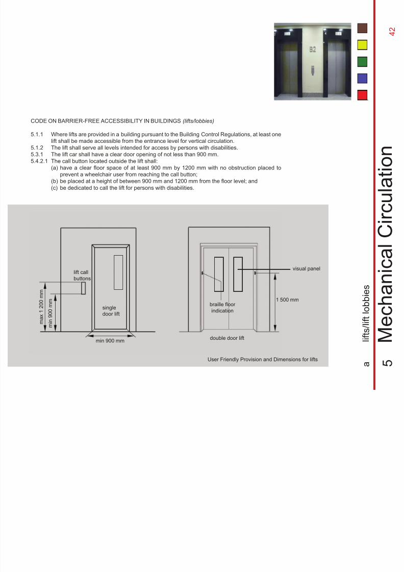
Where lifts are provided in a building pursuant to the Building Control Regulations, at least one
lift shall be made accessible from the entrance level for vertical circulation.
The lift shall serve all levels intended for access by persons with disabilities.The lift car shall have a clear door opening of not less than 900 mm.
The call button located outside the lift shall:
(a)
(b)
(c)
have a clear floor space of at least 900 mm by 1200 mm with no obstruction placed to
prevent a wheelchair user from reaching the call button;
be placed at a height of between 900 mm and 1200 mm from the floor level; and
be dedicated to call the lift for persons with disabilities.
User Friendly Provision and Dimensions for lifts
visual panel
4 3 The lift’s control and operation mechanism
should be located and designed for easy
use by people of all abilities. As such,
these mechanisms should not impede
8/12/2019 Universal Design Guidelines
http://slidepdf.com/reader/full/universal-design-guidelines 58/103
Lift Car Provision
Special Recommendations for Visually Impaired
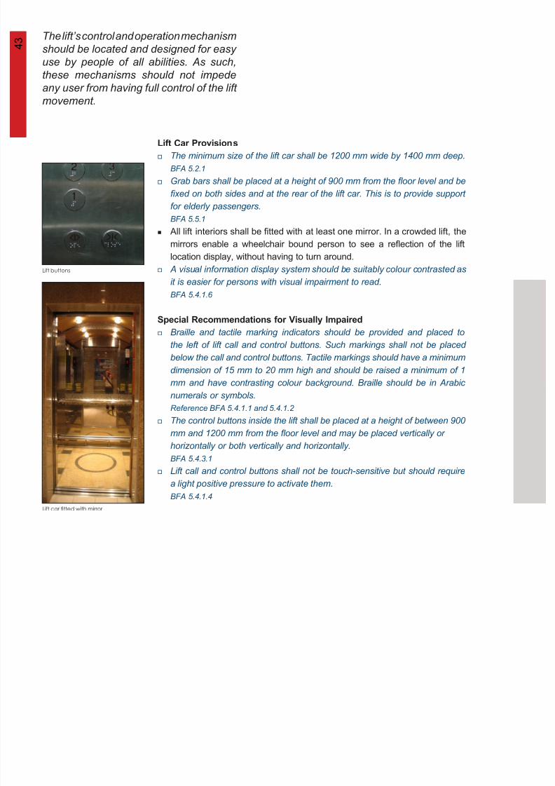
The minimum size of the lift car shall be 1200 mm wide by 1400 mm deep.
BFA 5.2.1
Grab bars shall be placed at a height of 900 mm from the floor level and be
fixed on both sides and at the rear of the lift car. This is to provide support
for elderly passengers.
BFA 5.5.1
All lift interiors shall be fitted with at least one mirror. In a crowded lift, the
mirrors enable a wheelchair bound person to see a reflection of the lift
location display, without having to turn around.
A visual information display system should be suitably colour contrasted as
it is easier for persons with visual impairment to read.
BFA 5.4.1.6
Braille and tactile marking indicators should be provided and placed to
the left of lift call and control buttons. Such markings shall not be placed
below the call and control buttons. Tactile markings should have a minimum
dimension of 15 mm to 20 mm high and should be raised a minimum of 1
mm and have contrasting colour background. Braille should be in Arabic
numerals or symbols.
Reference BFA 5.4.1.1 and 5.4.1.2
The control buttons inside the lift shall be placed at a height of between 900
mm and 1200 mm from the floor level and may be placed vertically or
horizontally or both vertically and horizontally.
BFA 5.4.3.1
Lift call and control buttons shall not be touch-sensitive but should require
a light positive pressure to activate them.BFA 5.4.1.4
these mechanisms should not impede
any user from having full control of the lift
movement.
Lift buttons
Lift car fitted with mirror
s
4 4
8/12/2019 Universal Design Guidelines
http://slidepdf.com/reader/full/universal-design-guidelines 59/103
Elevation of Side of Lift Car from the Interior
horizontal
control panel
min
height of
900 mm
max
height of
1 200 mm
min height of
handrail
900 mm
min
1 200 mm
wide
min
1 400 mm
deep
CODE ON BARRIER-FREE ACCESSIBILITY IN BUILDINGS (lifts/lift cars)
5.4.1.1
5.4.1.2
5.4.3.1
5.5.1
5
M e c h a n
i c a l C i r c u l a t i o n
a
l i f t s / l i f t c a r s
Dimensions of Lift Car
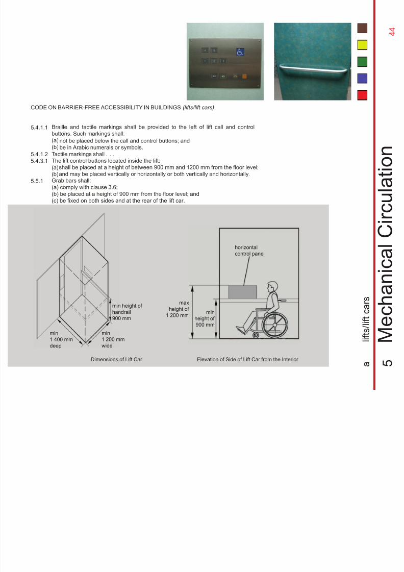
Tactile markings shall . . .
The lift control buttons located inside the lift:
(a)
(b)
shall be placed at a height of between 900 mm and 1200 mm from the floor level;
and may be placed vertically or horizontally or both vertically and horizontally.Grab bars shall:
(a) comply with clause 3.6;
(b) be placed at a height of 900 mm from the floor level; and
(c) be fixed on both sides and at the rear of the lift car.
Braille and tactile markings shall be provided to the left of lift call and control
buttons. Such markings shall:
(a)
(b)
not be placed below the call and control buttons; and
be in Arabic numerals or symbols.
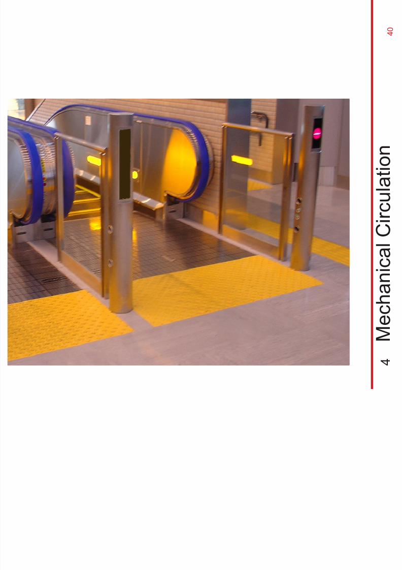
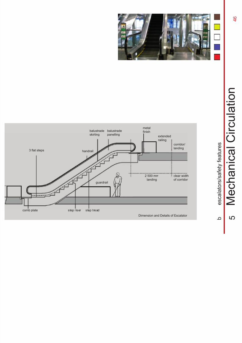
4 5 Escalators are efficient in moving a large
number of people. Attention should be
paid to ensure safety on the escalators as
well as landings. The provision of a buffer
8/12/2019 Universal Design Guidelines
http://slidepdf.com/reader/full/universal-design-guidelines 60/103
well as landings. The provision of a buffer
area at the landings is recommended for
slower moving passengers and to avoid
congestion.
Additonal railing at landing
Yellow marking on steps
Headroom warning
Escalator Provisions
Escalators Safety
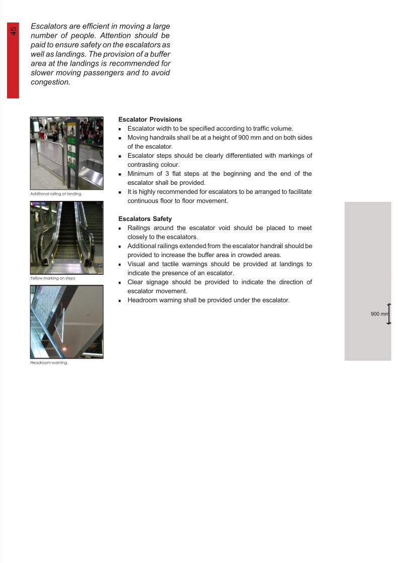
Escalator width to be specified according to traffic volume.
Moving handrails shall be at a height of 900 mm and on both sides
of the escalator.
Escalator steps should be clearly differentiated with markings of
contrasting colour.
Minimum of 3 flat steps at the beginning and the end of the
escalator shall be provided.
It is highly recommended for escalators to be arranged to facilitate
continuous floor to floor movement.
Railings around the escalator void should be placed to meet
closely to the escalators.
Additional railings extended from the escalator handrail should be
provided to increase the buffer area in crowded areas.
Visual and tactile warnings should be provided at landings to
indicate the presence of an escalator.
Clear signage should be provided to indicate the direction of
escalator movement.
Headroom warning shall be provided under the escalator.
900 mm
4 6
8/12/2019 Universal Design Guidelines
http://slidepdf.com/reader/full/universal-design-guidelines 61/103
3 flat steps
balustrade
skirting
balustrade
panelling
handrail
metalfinish
corridor/
landing
clear width
of corridor
2 500 mm
landing
step riser step treadcomb plate
guardrail
5
M e c h a n i c a l C i r c u l a t i o n
b
e s c a l a t o r s / s a f e
t y f e a t u r e s
Dimension and Details of Escalator
extended
railing

8/12/2019 Universal Design Guidelines
http://slidepdf.com/reader/full/universal-design-guidelines 62/103

8/12/2019 Universal Design Guidelines
http://slidepdf.com/reader/full/universal-design-guidelines 63/103
4 7
8/12/2019 Universal Design Guidelines
http://slidepdf.com/reader/full/universal-design-guidelines 64/103
6
F a c i l i t i e
s
4 8
8/12/2019 Universal Design Guidelines
http://slidepdf.com/reader/full/universal-design-guidelines 65/103
4 9
8/12/2019 Universal Design Guidelines
http://slidepdf.com/reader/full/universal-design-guidelines 66/103
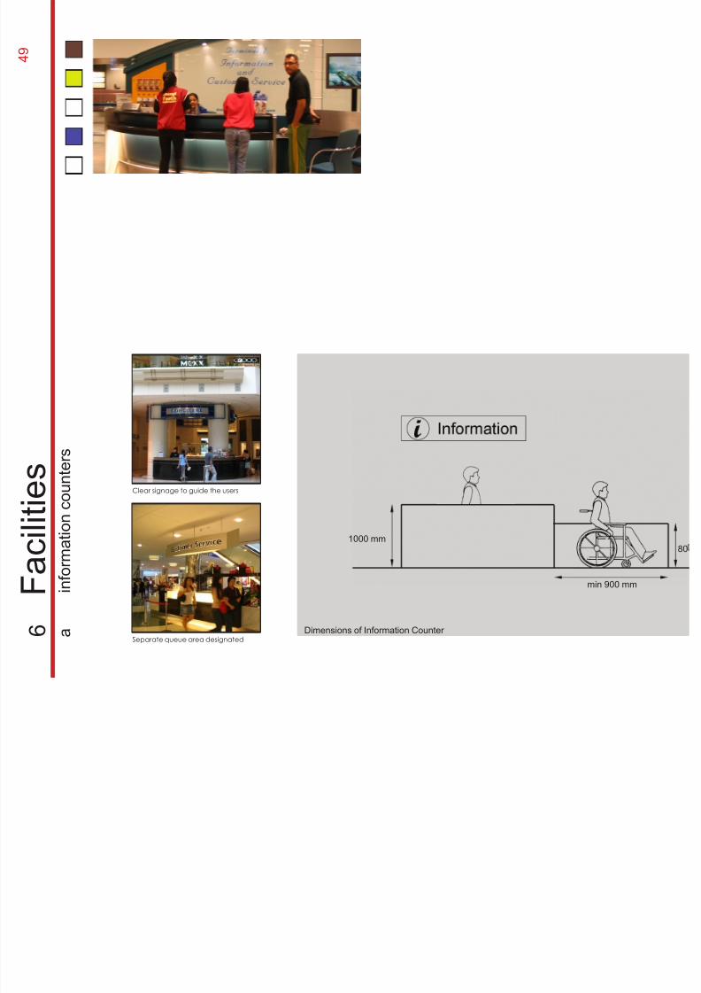
Separate queue area designated
Clear signage to guide the users
min 900 mm
801000 mm
6
F a c i l i t i e
s
a
i n f o r m a
t i o n c o u n
t e r s
Dimensions of Information Counter
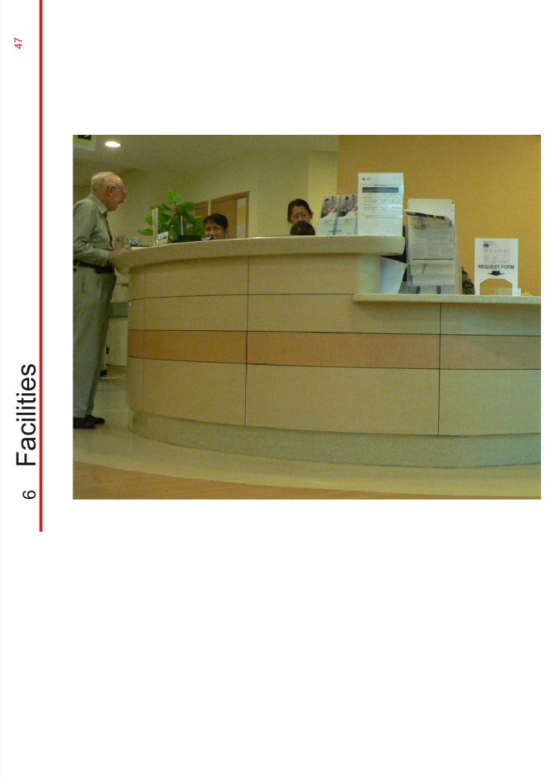
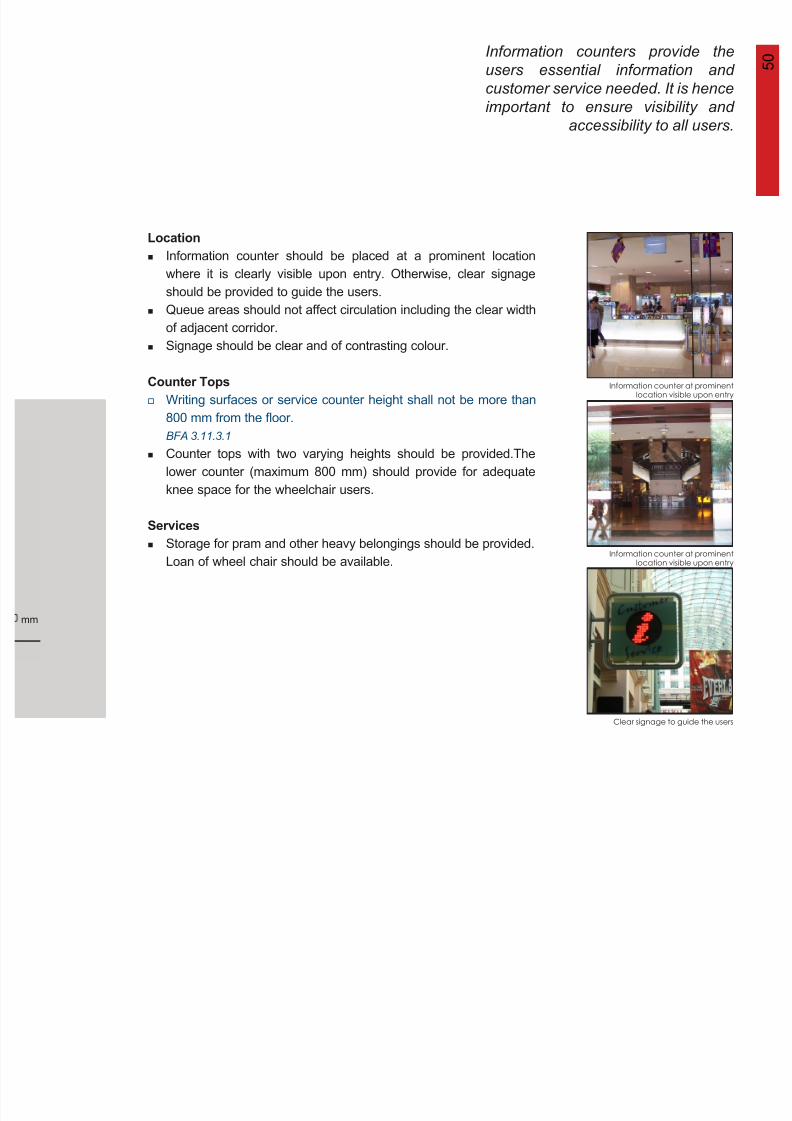
Information counters provide the
users essential information and
customer service needed. It is hence
important to ensure visibility and
accessibility to all users
5 0
8/12/2019 Universal Design Guidelines
http://slidepdf.com/reader/full/universal-design-guidelines 67/103
Location
Counter Tops
Services
Information counter at prominentlocation visible upon entry
Clear signage to guide the users
accessibility to all users.
Information counter at prominentlocation visible upon entry
mm
Information counter should be placed at a prominent location
where it is clearly visible upon entry. Otherwise, clear signage
should be provided to guide the users.Queue areas should not affect circulation including the clear width
of adjacent corridor.
Signage should be clear and of contrasting colour.
Writing surfaces or service counter height shall not be more than
800 mm from the floor.BFA 3.11.3.1
Counter tops with two varying heights should be provided.The
lower counter (maximum 800 mm) should provide for adequate
knee space for the wheelchair users.
Storage for pram and other heavy belongings should be provided.
Loan of wheel chair should be available.
5 1
8/12/2019 Universal Design Guidelines
http://slidepdf.com/reader/full/universal-design-guidelines 68/103
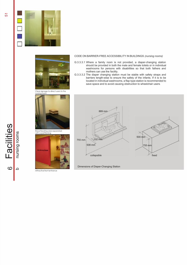
Clear signage to direct users to thenursing room
Breastfeeding area separatedwith a partitioning
Attractive front entrance
755 mm
500 mm
fixedcollapsible
889 mm
755 mm
508 mm
102 mm
CODE ON BARRIER-FREE ACCESSIBILITY IN BUILDINGS (nursing rooms)
G.3.3.3.1
G.3.3.3.2
6
F a c i l i t i e
s
b
n u r s
i n g r o o m s
Where a family room is not provided, a diaper-changing station
should be provided in both the male and female toilets or in individual
washrooms for persons with disabilities so that both fathers andmothers can use the facility.
The diaper changing station must be stable with safety straps and
barriers length-wise to ensure the safety of the infants. If it is to be
located in individual washrooms, a flap-type station is recommended to
save space and to avoid causing obstruction to wheelchair users.
Dimensions of Diaper-Changing Station
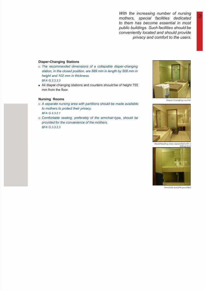
With the increasing number of nursing
mothers, special facilities dedicated
to them has become essential in most
public buildings. Such facilities should be
conveniently located and should provide
5 2
8/12/2019 Universal Design Guidelines
http://slidepdf.com/reader/full/universal-design-guidelines 69/103
Diaper-Changing Stations
Nursing Rooms
Diaper changing counter
Breastfeeding area, separated with asliding door
Armchair and sink provided
conveniently located and should provide
privacy and comfort to the users.
The recommended dimensions of a collapsible diaper-changing
station, in the closed position, are 889 mm in length by 508 mm in
height and 102 mm in thickness.BFA G.3.3.3.3
All diaper-changing stations and counters should be of height 755
mm from the floor.
A separate nursing area with partitions should be made available
to mothers to protect their privacy.
BFA G.3.3.2.1
Comfortable seating, preferably of the armchair-type, should be
provided for the convenience of the mothers.
BFA G.3.3.2.3
5 3
8/12/2019 Universal Design Guidelines
http://slidepdf.com/reader/full/universal-design-guidelines 70/103
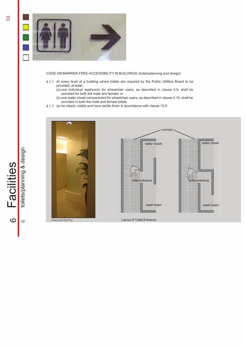
Adequate lighting
toilet entrance toilet entrance
corridor
wash basin wash basin
water closet water closet
CODE ON BARRIER-FREE ACCESSIBILITY IN BUILDINGS (toilets/planning and design)
4.1.1
4.1.7
Layout of Toilet Entrance 6
F a c i l i t i e
s
c
t o i l e t s / p l a n n
i n g
& d e s
i g n
At every level of a building where toilets are required by the Public Utilities Board to be
provided, at least:
(a)
(b)
(a) be clearly visible and have tactile finish in accordance with clause 10.5.
one individual washroom for wheelchair users, as described in clause 4.9, shall beprovided for both the male and female; or
one water closet compartment for wheelchair users, as described in clause 4.10, shall be
provided in both the male and female toilets.
5 4The toilet is a necessary provision that
should be included as part of the facilities
in public buildings. It is important to place
them discreetly and yet easily identified
and accessible.
8/12/2019 Universal Design Guidelines
http://slidepdf.com/reader/full/universal-design-guidelines 71/103
Doorless entrance to toilet
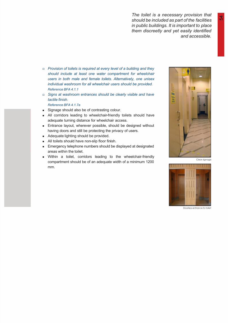
Clear signage
Provision of toilets is required at every level of a building and they
should include at least one water compartment for wheelchair
users in both male and female toilets. Alternatively, one unisex
individual washroom for all wheelchair users should be provided. Reference BFA 4.1.1
Signs at washroom entrances should be clearly visible and have
tactile finish.
Reference BFA 4.1.7a
Signage should also be of contrasting colour.
All corridors leading to wheelchair-friendly toilets should have
adequate turning distance for wheelchair access.
Entrance layout, wherever possible, should be designed without
having doors and still be protecting the privacy of users.
Adequate lighting should be provided.
All toilets should have non-slip floor finish.
Emergency telephone numbers should be displayed at designated
areas within the toilet.
Within a toilet, corridors leading to the wheelchair-friendly
compartment should be of an adequate width of a minimum 1200mm.
5 5
8/12/2019 Universal Design Guidelines
http://slidepdf.com/reader/full/universal-design-guidelines 72/103
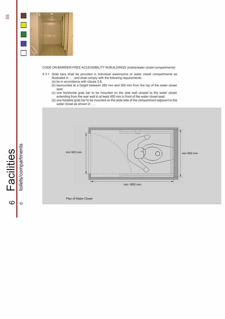
Grab bars shall be provided in individual washrooms or water closet compartments as
illustrated in . . . and shall comply with the following requirements:
(a) be in accordance with clause 3.6;(b)
(c)
(d)
bemounted at a height between 280 mm and 300 mm from the top of the water closet
seat;
one horizontal grab bar to be mounted on the side wall closest to the water closet
extending from the rear wall to at least 450 mm in front of the water closet seat;
one foldable grab bar to be mounted on the wide side of the compartment adjacent to the
water closet as shown in . . .
CODE ON BARRIER-FREE ACCESSIBILITY IN BUILDINGS (toilets/water closet compartments)
4.3.1
min 900 mm
min 1800 mm
min 950 mm
6
F a c i l i t i e
s
c
t o i l e t s / c o m p a r
t m e n
t s
Plan of Water Closet
It is a common practice that standard
water closet compartments are given
minimum dimensions but these small
compartments do not normally serve
the ambulant disabled well. Considering
5 6
8/12/2019 Universal Design Guidelines
http://slidepdf.com/reader/full/universal-design-guidelines 73/103
users with different abilities, water closet
compartments should be designed tocater for their convenience and safety.
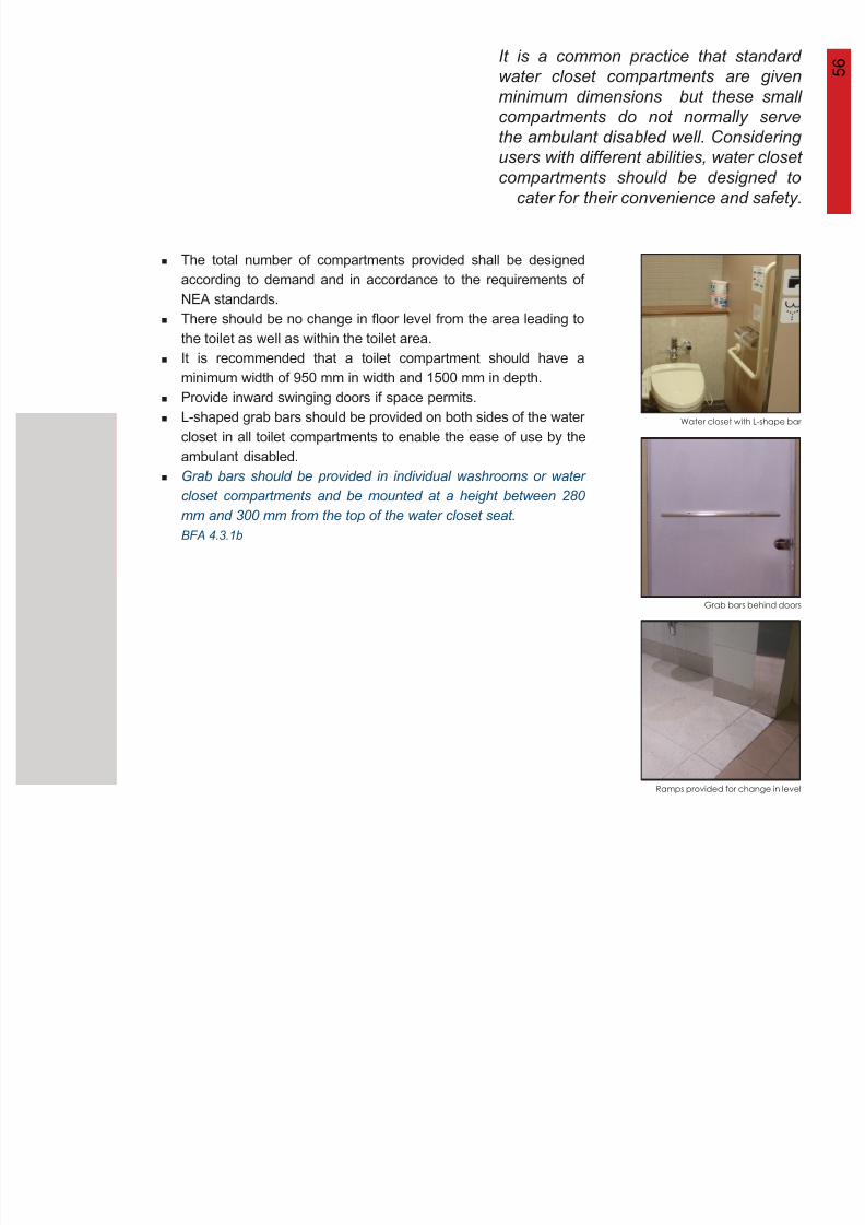
Water closet with L-shape bar
Grab bars behind doors
Ramps provided for change in level
The total number of compartments provided shall be designed
according to demand and in accordance to the requirements of
NEA standards.
There should be no change in floor level from the area leading tothe toilet as well as within the toilet area.
It is recommended that a toilet compartment should have a
minimum width of 950 mm in width and 1500 mm in depth.
Provide inward swinging doors if space permits.
L-shaped grab bars should be provided on both sides of the water
closet in all toilet compartments to enable the ease of use by the
ambulant disabled.
Grab bars should be provided in individual washrooms or water
closet compartments and be mounted at a height between 280
mm and 300 mm from the top of the water closet seat.
BFA 4.3.1b
5 7
8/12/2019 Universal Design Guidelines
http://slidepdf.com/reader/full/universal-design-guidelines 74/103
turning radius
of 600 mm
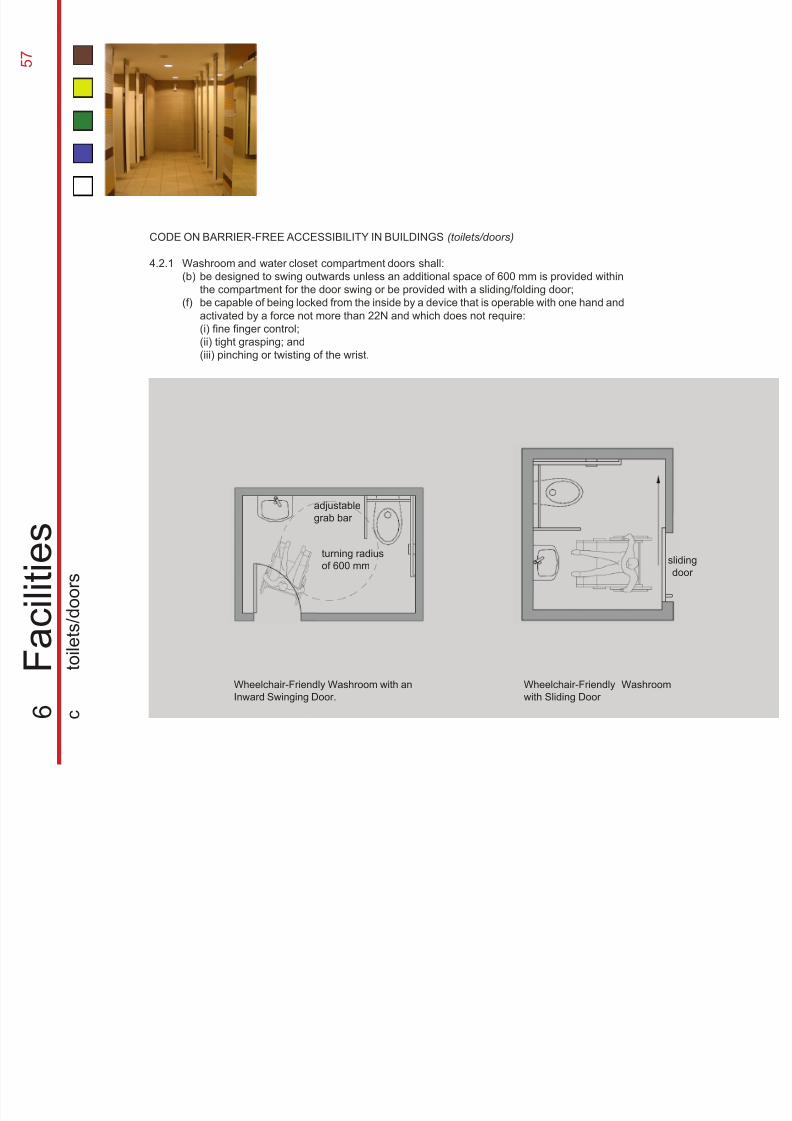
Wheelchair-Friendly Washroom with an
Inward Swinging Door.
Wheelchair-Friendly Washroom
with Sliding Door
slidingdoor
adjustable
grab bar
CODE ON BARRIER-FREE ACCESSIBILITY IN BUILDINGS (toilets/doors)
4.2.1 Washroom and water closet compartment doors shall:
(b)
(f)
6
F a c i l i t i e
s
c
t o i l e t s / d o o r s
be designed to swing outwards unless an additional space of 600 mm is provided within
the compartment for the door swing or be provided with a sliding/folding door;be capable of being locked from the inside by a device that is operable with one hand and
activated by a force not more than 22N and which does not require:
(i) fine finger control;
(ii) tight grasping; and
(iii) pinching or twisting of the wrist.
5 8Doors can be the largest obstacle and yet
a necessary item in a toilet, especially in
the case of a wheelchair-friendly toilet.
Therefore there is a need to install doors
that allows users to open with ease and
itho t impeding other sers
8/12/2019 Universal Design Guidelines
http://slidepdf.com/reader/full/universal-design-guidelines 75/103
without impeding other users.
Grab bar at door
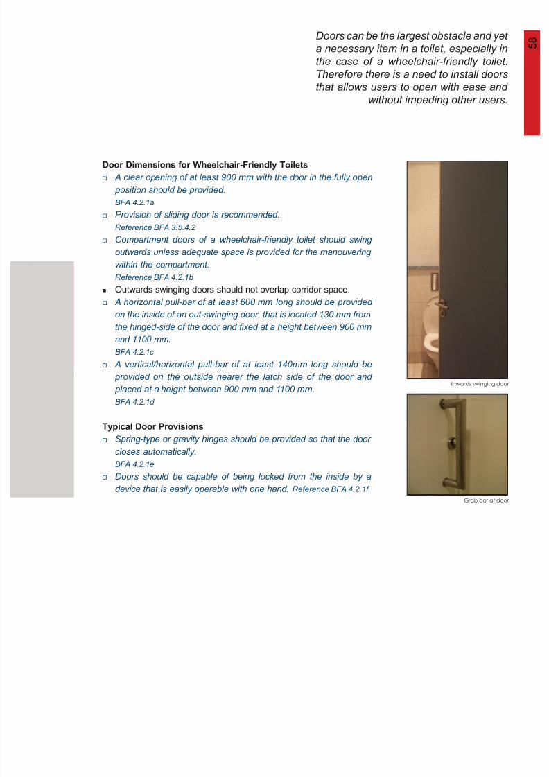
Inwards swinging door
Door Dimensions for Wheelchair-Friendly Toilets
Typical Door Provisions
A clear opening of at least 900 mm with the door in the fully open
position should be provided.
BFA 4.2.1aProvision of sliding door is recommended.
Reference BFA 3.5.4.2
Compartment doors of a wheelchair-friendly toilet should swing
outwards unless adequate space is provided for the manouvering
within the compartment.
Reference BFA 4.2.1b
Outwards swinging doors should not overlap corridor space.
A horizontal pull-bar of at least 600 mm long should be provided
on the inside of an out-swinging door, that is located 130 mm from
the hinged-side of the door and fixed at a height between 900 mm
and 1100 mm.
BFA 4.2.1c
A vertical/horizontal pull-bar of at least 140mm long should be
provided on the outside nearer the latch side of the door and
placed at a height between 900 mm and 1100 mm. BFA 4.2.1d
Spring-type or gravity hinges should be provided so that the door
closes automatically.
BFA 4.2.1e
Doors should be capable of being locked from the inside by a
device that is easily operable with one hand. Reference BFA 4.2.1f
5 9
8/12/2019 Universal Design Guidelines
http://slidepdf.com/reader/full/universal-design-guidelines 76/103
1 750 mm
750 mm 450 mm
1 750 mm
480 mm
toilet roll dispenser
folding/drop bar
300 mm
max 480 mm
900 mm
510 mm
450 mm
wash basin
800 mm
140 mm
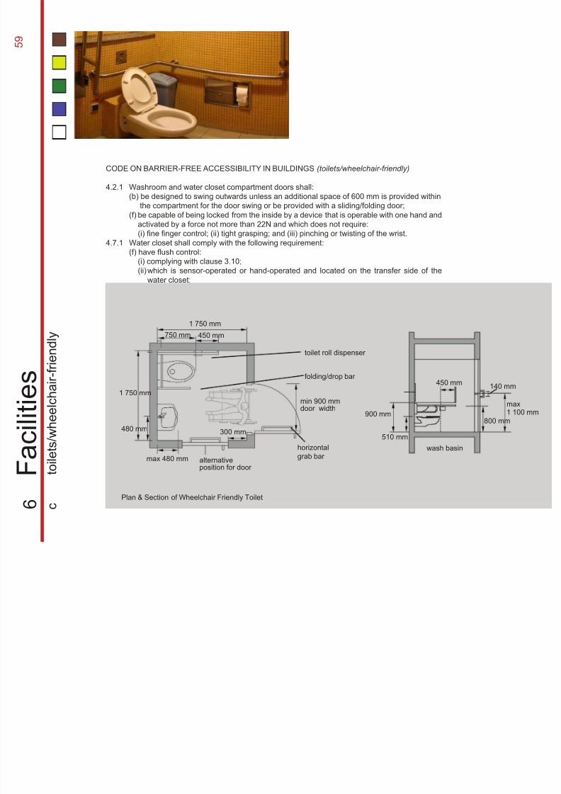
CODE ON BARRIER-FREE ACCESSIBILITY IN BUILDINGS (toilets/wheelchair-friendly)
4.2.1
4.7.1
Washroom and water closet compartment doors shall:
(b) be designed to swing outwards unless an additional space of 600 mm is provided within
(f)
Water closet shall comply with the following requirement:
(f) have flush control:
6
F a c i l i t i e
s
c
t o i l e t s / w h e e
l c h
a i r - f r i e n
d l y
Plan & Section of Wheelchair Friendly Toilet
max1 100 mm
min 900 mmdoor width
horizontal
grab bar alternativeposition for door
the compartment for the door swing or be provided with a sliding/folding door;be capable of being locked from the inside by a device that is operable with one hand and
activated by a force not more than 22N and which does not require:
(i) fine finger control; (ii) tight grasping; and (iii) pinching or twisting of the wrist.
(i) complying with clause 3.10;
(ii)which is sensor-operated or hand-operated and located on the transfer side of the
water closet;
6 0Wheelchair-friendly toilets are catered
specially for the wheelchair-bound
users. Therefore, the design should
take into consideration their special
needs. The installation of sanitary
equipment and other fittings should
8/12/2019 Universal Design Guidelines
http://slidepdf.com/reader/full/universal-design-guidelines 77/103
equipment and other fittings should
ensure their easy usage.
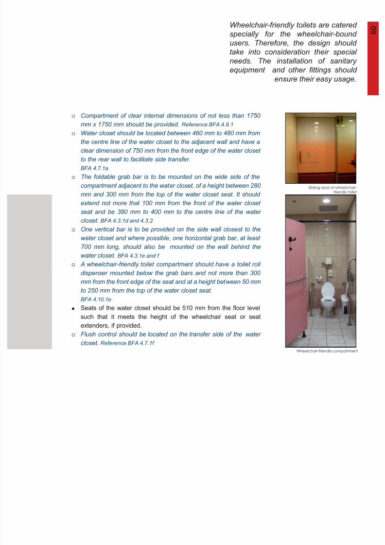
Wheelchair-friendly compartment
Sliding door of wheelchair-friendly toilet
Compartment of clear internal dimensions of not less than 1750
mm x 1750 mm should be provided. Reference BFA 4.9.1
Water closet should be located between 460 mm to 480 mm from
the centre line of the water closet to the adjacent wall and have aclear dimension of 750 mm from the front edge of the water closet
to the rear wall to facilitate side transfer.
BFA 4.7.1a
The foldable grab bar is to be mounted on the wide side of the
compartment adjacent to the water closet, of a height between 280
mm and 300 mm from the top of the water closet seat. It should
extend not more that 100 mm from the front of the water closet
seat and be 380 mm to 400 mm to the centre line of the water
closet. BFA 4.3.1d and 4.3.2
One vertical bar is to be provided on the side wall closest to the
water closet and where possible, one horizontal grab bar, at least
700 mm long, should also be mounted on the wall behind the
water closet. BFA 4.3.1e and f
A wheelchair-friendly toilet compartment should have a toilet roll
dispenser mounted below the grab bars and not more than 300mm from the front edge of the seat and at a height between 50 mm
to 250 mm from the top of the water closet seat.
BFA 4.10.1e
Seats of the water closet should be 510 mm from the floor level
such that it meets the height of the wheelchair seat or seat
extenders, if provided.
Flush control should be located on the transfer side of the water
closet. Reference BFA 4.7.1f
6 1
8/12/2019 Universal Design Guidelines
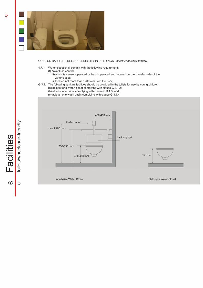
http://slidepdf.com/reader/full/universal-design-guidelines 78/103
460-480 mm
max 1 200 mm
750-850 mm
back support
450-480 mm
flush control
350 mm
Child-size Water Closet Adult-size Water Closet
6
F a c i l i t i e
s
c
t o i l e t s / w h e e
l c h a
i r - f r i e n
d l y
CODE ON BARRIER-FREE ACCESSIBILITY IN BUILDINGS (toilets/wheelchair-friendly)
4.7.1
G.3.1.1
Water closet shall comply with the following requirement:
(f) have flush control:
The following sanitary facilities should be provided in the toilets for use by young children:
(a) at least one water-closet complying with clause G.3.1.2;
(b) at least one urinal complying with clause G.3.1.3; and
(c) at least one wash basin complying with clause G.3.1.4.
(ii)
(iii)located not more than 1200 mm from the floor;
which is sensor-operated or hand-operated and located on the transfer side of thewater closet;
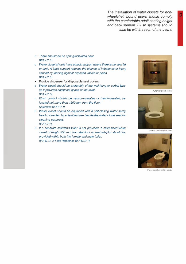
6 2The installation of water closets for non-
wheelchair bound users should comply
with the comfortable adult seating height
and back support. Flush systems should
also be within reach of the users.
8/12/2019 Universal Design Guidelines
http://slidepdf.com/reader/full/universal-design-guidelines 79/103
Water closet at child’s height
Automatic flash sensor
Water closet with back rest
There should be no spring-activated seat.
BFA 4.7.1c
Water closet should have a back support where there is no seat lid
or tank. A back support reduces the chance of imbalance or injurycaused by leaning against exposed valves or pipes.
BFA 4.7.1d
Provide dispenser for disposable seat covers.
Water closet should be preferably of the wall-hung or corbel type
as it provides additional space at toe level.
BFA 4.7.1e
Flush control should be sensor-operated or hand-operated, be
located not more than 1200 mm from the floor.
Reference BFA 4.7.1f
Water closet should be equipped with a self-closing water spray
head connected by a flexible hose beside the water closet seat for
cleaning purposes.
BFA 4.7.1g
If a separate children’s toilet is not provided, a child-sized water
closet of height 350 mm from the floor or seat adaptor should be provided within both the female and male toilet.
BFA G.3.1.2.1 and Reference BFA G.3.1.1
6 3
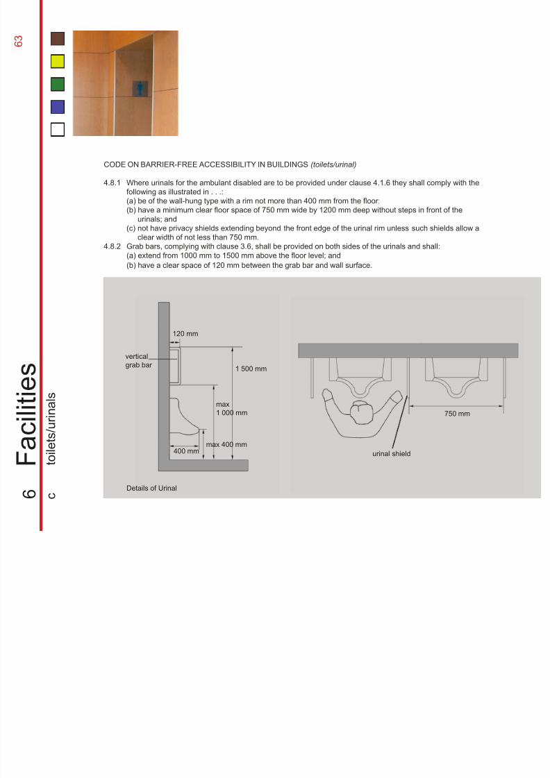
8/12/2019 Universal Design Guidelines
http://slidepdf.com/reader/full/universal-design-guidelines 80/103
xcs
CODE ON BARRIER-FREE ACCESSIBILITY IN BUILDINGS (toilets/urinal)
4.8.1
4.8.2
6
F a c i l i t i e s
c
t o i l e t s / u r i n a
l s
Where urinals for the ambulant disabled are to be provided under clause 4.1.6 they shall comply with the
following as illustrated in . . .:
(a) be of the wall-hung type with a rim not more than 400 mm from the floor;(b) have a minimum clear floor space of 750 mm wide by 1200 mm deep without steps in front of the
(c)
Grab bars, complying with clause 3.6, shall be provided on both sides of the urinals and shall:
(a) extend from 1000 mm to 1500 mm above the floor level; and
(b) have a clear space of 120 mm between the grab bar and wall surface.
urinals; and
not have privacy shields extending beyond the front edge of the urinal rim unless such shields allow a
clear width of not less than 750 mm.
Details of Urinal
120 mm
vertical
grab bar
400 mmmax 400 mm
1 500 mm
max
1 000 mm
urinal shield
750 mm
Details of Urinal
6 4Besides the provision of standard urinals,
there is a need for the installation of
vertical grab bars on top of the urinal to
assist the ambulant disabled. Urinals for
children should also be provided.
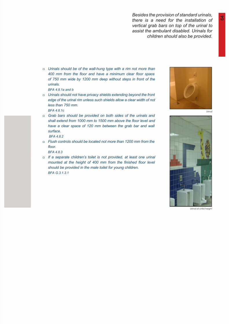
8/12/2019 Universal Design Guidelines
http://slidepdf.com/reader/full/universal-design-guidelines 81/103
Urinal at child height
Urinal
Urinals should be of the wall-hung type with a rim not more than
400 mm from the floor and have a minimum clear floor space
of 750 mm wide by 1200 mm deep without steps in front of the
urinals. BFA 4.8.1a and b
Urinals should not have privacy shields extending beyond the front
edge of the urinal rim unless such shields allow a clear width of not
less than 750 mm.
BFA 4.8.1c
Grab bars should be provided on both sides of the urinals and
shall extend from 1000 mm to 1500 mm above the floor level and
have a clear space of 120 mm between the grab bar and wall
surface.
BFA 4.8.2
Flush controls should be located not more than 1200 mm from the
floor.
BFA 4.8.3
If a separate children’s toilet is not provided, at least one urinal
mounted at the height of 400 mm from the finished floor levelshould be provided in the male toilet for young children.
BFA G.3.1.3.1
6 5
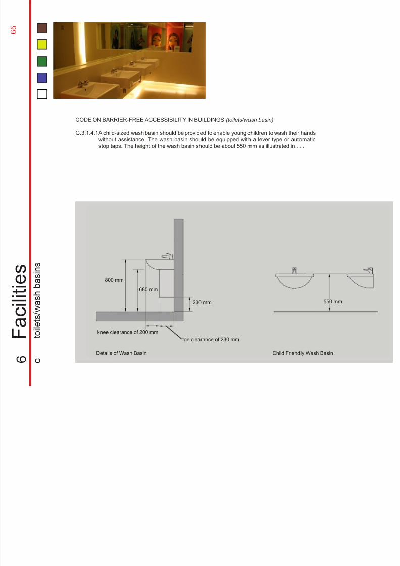
8/12/2019 Universal Design Guidelines
http://slidepdf.com/reader/full/universal-design-guidelines 82/103
800 mm
680 mm
knee clearance of 200 mm
toe clearance of 230 mm
230 mm 550 mm
Child Friendly Wash Basin
CODE ON BARRIER-FREE ACCESSIBILITY IN BUILDINGS (toilets/wash basin)
G.3.1.4.1
6
F a c i l i t i e s
c
t o i l e t s / w a s
h b a s
i n s
A child-sized wash basin should be provided to enable young children to wash their hands
without assistance. The wash basin should be equipped with a lever type or automatic
stop taps. The height of the wash basin should be about 550 mm as illustrated in . . .
Details of Wash Basin
6 6Wash basins are important components
in toilets. They are normally installed
outside water closet compartments for the
convenience of users. The arrangement
should be extended to suit wheelchair
users and children alike.
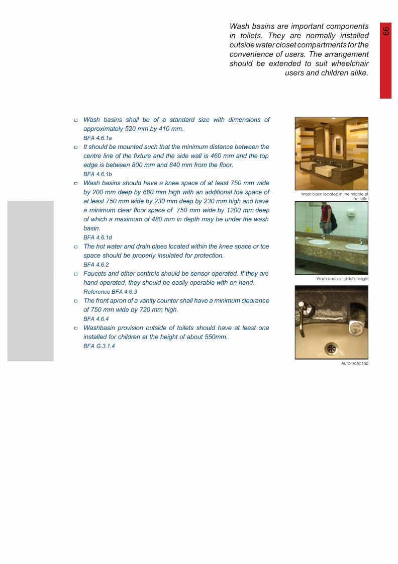
8/12/2019 Universal Design Guidelines
http://slidepdf.com/reader/full/universal-design-guidelines 83/103
Wash basin located in the middle ofthe toilet
Wash basin at child’s height
Automatic tap
Wash basins shall be of a standard size with dimensions of
approximately 520 mm by 410 mm.
BFA 4.6.1a
It should be mounted such that the minimum distance between thecentre line of the fixture and the side wall is 460 mm and the top
edge is between 800 mm and 840 mm from the floor.
BFA 4.6.1b
Wash basins should have a knee space of at least 750 mm wide
by 200 mm deep by 680 mm high with an additional toe space of
at least 750 mm wide by 230 mm deep by 230 mm high and have
a minimum clear floor space of 750 mm wide by 1200 mm deep
of which a maximum of 480 mm in depth may be under the wash
basin.
BFA 4.6.1d
The hot water and drain pipes located within the knee space or toe
space should be properly insulated for protection.
BFA 4.6.2
Faucets and other controls should be sensor operated. If they are
hand operated, they should be easily operable with on hand. Reference BFA 4.6.3
The front apron of a vanity counter shall have a minimum clearance
of 750 mm wide by 720 mm high.
BFA 4.6.4
Washbasin provision outside of toilets should have at least one
installed for children at the height of about 550mm.
BFA G.3.1.4
6 7
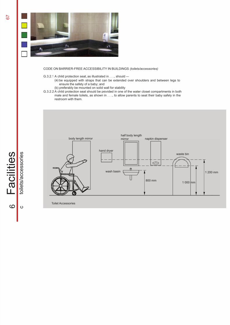
8/12/2019 Universal Design Guidelines
http://slidepdf.com/reader/full/universal-design-guidelines 84/103
body length mirror
hand dryer
half body length
mirror napkin dispenser
waste bin
wash basin
800 mm1 000 mm
1 200 mm
CODE ON BARRIER-FREE ACCESSIBILITY IN BUILDINGS (toilets/accessories)
G.3.2.1
G.3.2.2
6
F a c i l i t i e s
c
t o i l e t s / a c c e s s o r i e s
A child protection seat, as illustrated in . . ., should –-
(a)
(b) preferably be mounted on solid wall for stability
A child protection seat should be provided in one of the water closet compartments in both
male and female toilets, as shown in . . ., to allow parents to seat their baby safely in the
restroom with them.
be equipped with straps that can be extended over shoulders and between legs to
ensure the safety of a baby; and
Toilet Accessories
6 8Toilet accessories are essential
components for the functioning of
toilets. Therefore they should be
installed at appropriate positions to
ensure universal usage.
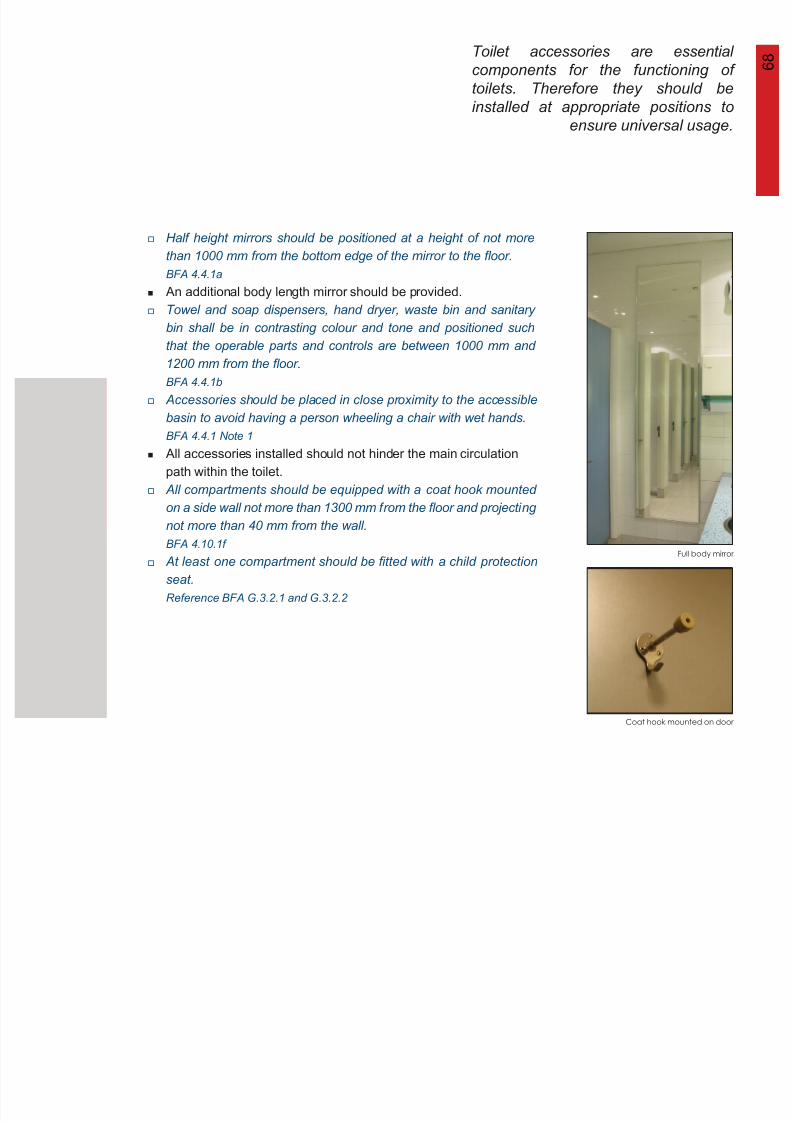
8/12/2019 Universal Design Guidelines
http://slidepdf.com/reader/full/universal-design-guidelines 85/103
Full body mirror
Coat hook mounted on door
Half height mirrors should be positioned at a height of not more
than 1000 mm from the bottom edge of the mirror to the floor.
BFA 4.4.1a
An additional body length mirror should be provided.Towel and soap dispensers, hand dryer, waste bin and sanitary
bin shall be in contrasting colour and tone and positioned such
that the operable parts and controls are between 1000 mm and
1200 mm from the floor.
BFA 4.4.1b
Accessories should be placed in close proximity to the accessible
basin to avoid having a person wheeling a chair with wet hands.
BFA 4.4.1 Note 1
All accessories installed should not hinder the main circulation
path within the toilet.
All compartments should be equipped with a coat hook mounted
on a side wall not more than 1300 mm from the floor and projecting
not more than 40 mm from the wall.
BFA 4.10.1f
At least one compartment should be fitted with a child protectionseat.
Reference BFA G.3.2.1 and G.3.2.2
6 9
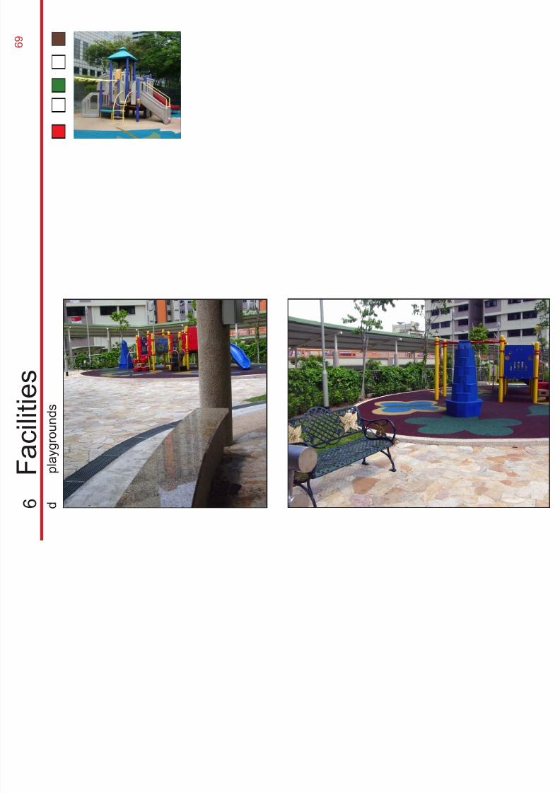
8/12/2019 Universal Design Guidelines
http://slidepdf.com/reader/full/universal-design-guidelines 86/103
6
F a c i l i t i e s
d
p l a y g r o u n
d s
7 0Playgrounds facilities have become
increasingly popular in commercial
buildings. The design of the playground
should accommodate children of all ages
and ability, and at the same time, provide
them with a safe playing environment.
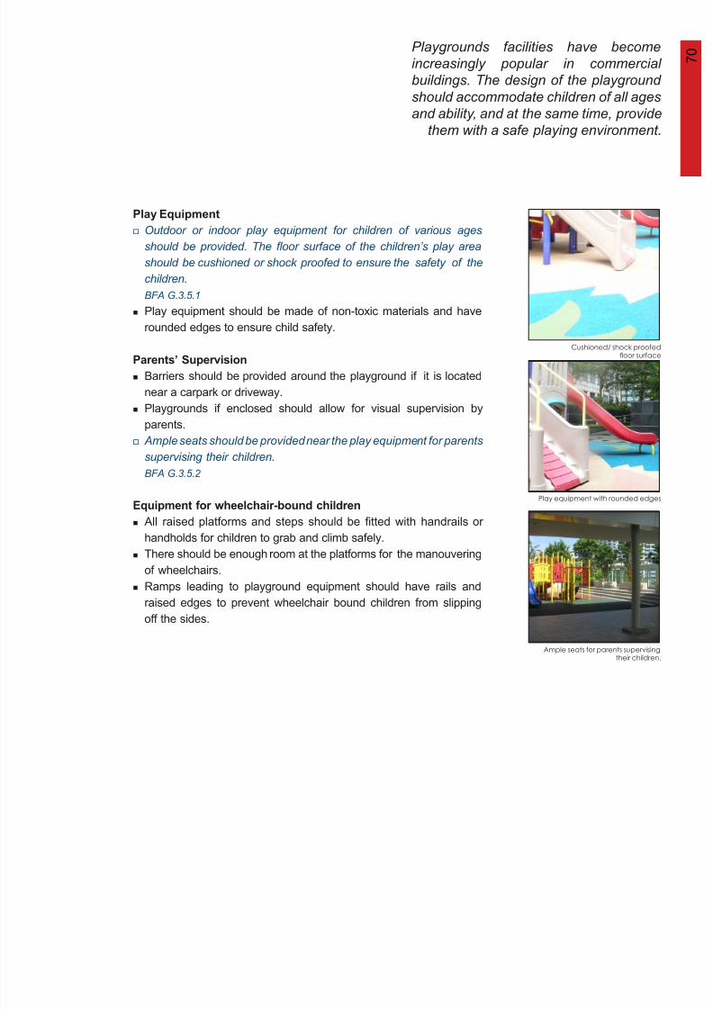
8/12/2019 Universal Design Guidelines
http://slidepdf.com/reader/full/universal-design-guidelines 87/103
Play Equipment
Parents’ Supervision
Equipment for wheelchair-bound children
Play equipment with rounded edges
Cushioned/ shock proofedfloor surface
Ample seats for parents supervisingtheir children.
Outdoor or indoor play equipment for children of various ages
should be provided. The floor surface of the children’s play area
should be cushioned or shock proofed to ensure the safety of thechildren.
BFA G.3.5.1
Play equipment should be made of non-toxic materials and have
rounded edges to ensure child safety.
Barriers should be provided around the playground if it is located
near a carpark or driveway.
Playgrounds if enclosed should allow for visual supervision by
parents.
Ample seats should be provided near the play equipment for parents
supervising their children.
BFA G.3.5.2
All raised platforms and steps should be fitted with handrails or
handholds for children to grab and climb safely.
There should be enough room at the platforms for the manouvering
of wheelchairs.
Ramps leading to playground equipment should have rails and
raised edges to prevent wheelchair bound children from slipping
off the sides.
7 1
8/12/2019 Universal Design Guidelines
http://slidepdf.com/reader/full/universal-design-guidelines 88/103
7 2
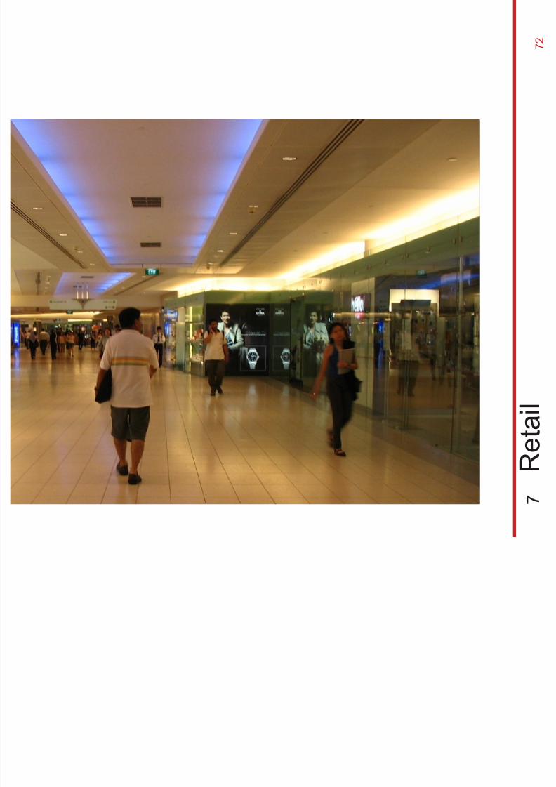
8/12/2019 Universal Design Guidelines
http://slidepdf.com/reader/full/universal-design-guidelines 89/103
7
R e t a i l
Supermarkets tend to be crowded andcluttered, as such, the narrow lanesmay become barriers to some. It is good practice to ensure that the design ofsupermarkets cater to the convenienceof all users through well designed
routes and signage as well as thoughtful
7 3
7 3
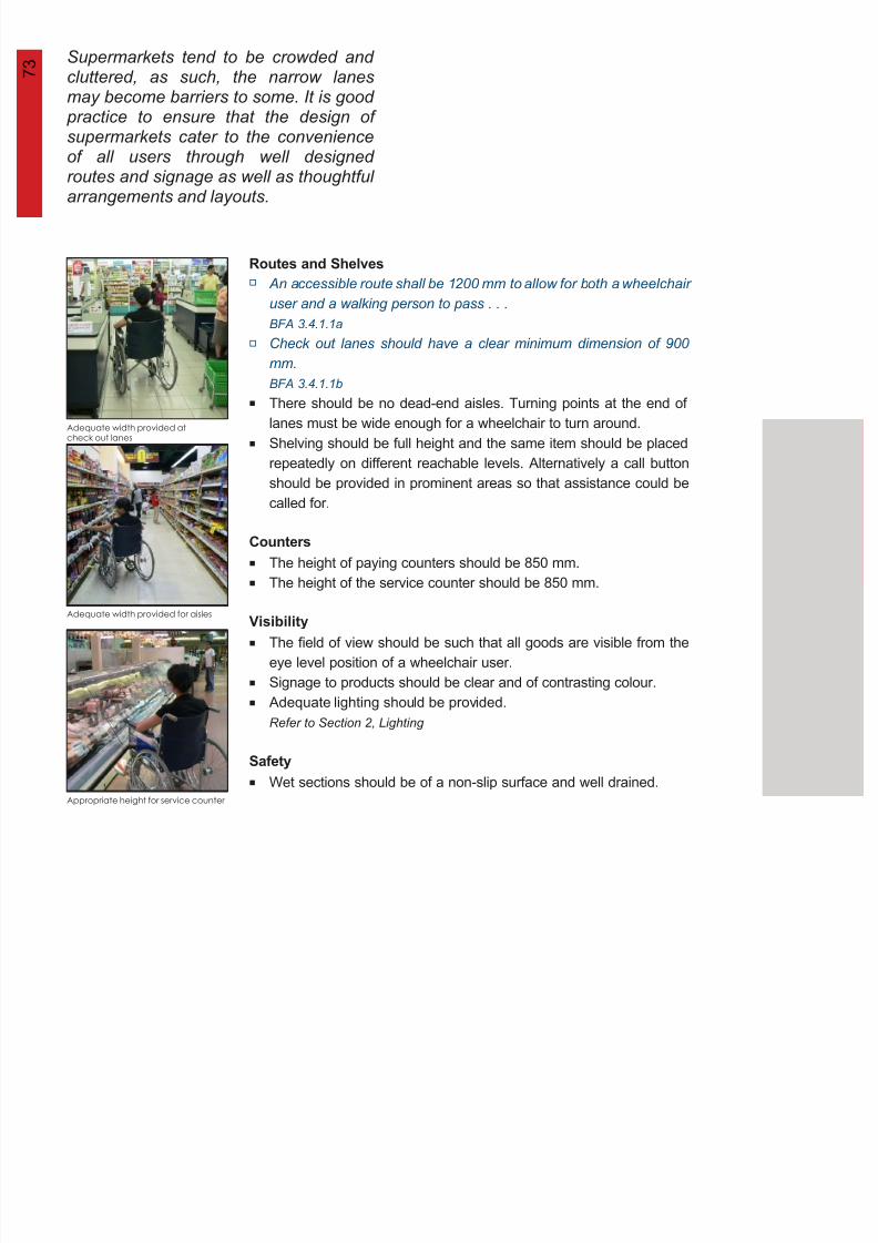
8/12/2019 Universal Design Guidelines
http://slidepdf.com/reader/full/universal-design-guidelines 90/103
routes and signage as well as thoughtfularrangements and layouts.
Adequate width provided atcheck out lanes
Adequate width provided for aisles
Appropriate height for service counter
Routes and Shelves
Counters
Visibility
Safety
An accessible route shall be 1200 mm to allow for both a wheelchair
user and a walking person to pass . . .
BFA 3.4.1.1aCheck out lanes should have a clear minimum dimension of 900
mm.
BFA 3.4.1.1b
There should be no dead-end aisles. Turning points at the end of
lanes must be wide enough for a wheelchair to turn around.
Shelving should be full height and the same item should be placed
repeatedly on different reachable levels. Alternatively a call button
should be provided in prominent areas so that assistance could be
called for.
The height of paying counters should be 850 mm.
The height of the service counter should be 850 mm.
The field of view should be such that all goods are visible from the
eye level position of a wheelchair user.
Signage to products should be clear and of contrasting colour.
Adequate lighting should be provided.
Refer to Section 2, Lighting
Wet sections should be of a non-slip surface and well drained.
7 4
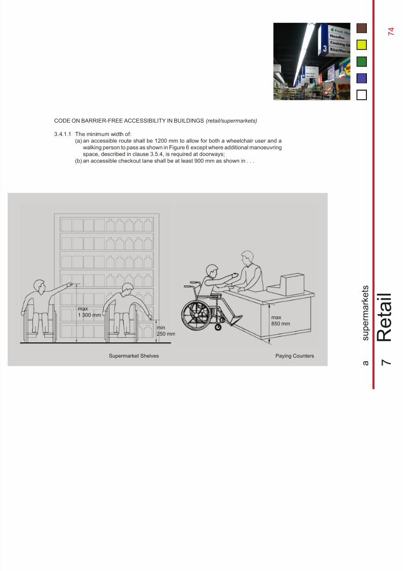
8/12/2019 Universal Design Guidelines
http://slidepdf.com/reader/full/universal-design-guidelines 91/103
min
250 mm
max
1 300 mm max
850 mm
CODE ON BARRIER-FREE ACCESSIBILITY IN BUILDINGS (retail/supermarkets)
3.4.1.1 The minimum width of:
(a)
(b)
Paying CountersSupermarket Shelves
7
R e t a i l
a
s u p e r m a r k e t s
an accessible route shall be 1200 mm to allow for both a wheelchair user and a
walking person to pass as shown in Figure 6 except where additional manoeuvring
space, described in clause 3.5.4, is required at doorways;an accessible checkout lane shall be at least 900 mm as shown in . . .
The fun of shopping can be stifled by
inconsiderate design and planning
layouts. Shops that try to display as
many items as possible often impede the
movement of some shoppers. Greater
attention needs to be paid to the circulation
in and around shops and kiosks
7 5
7 5
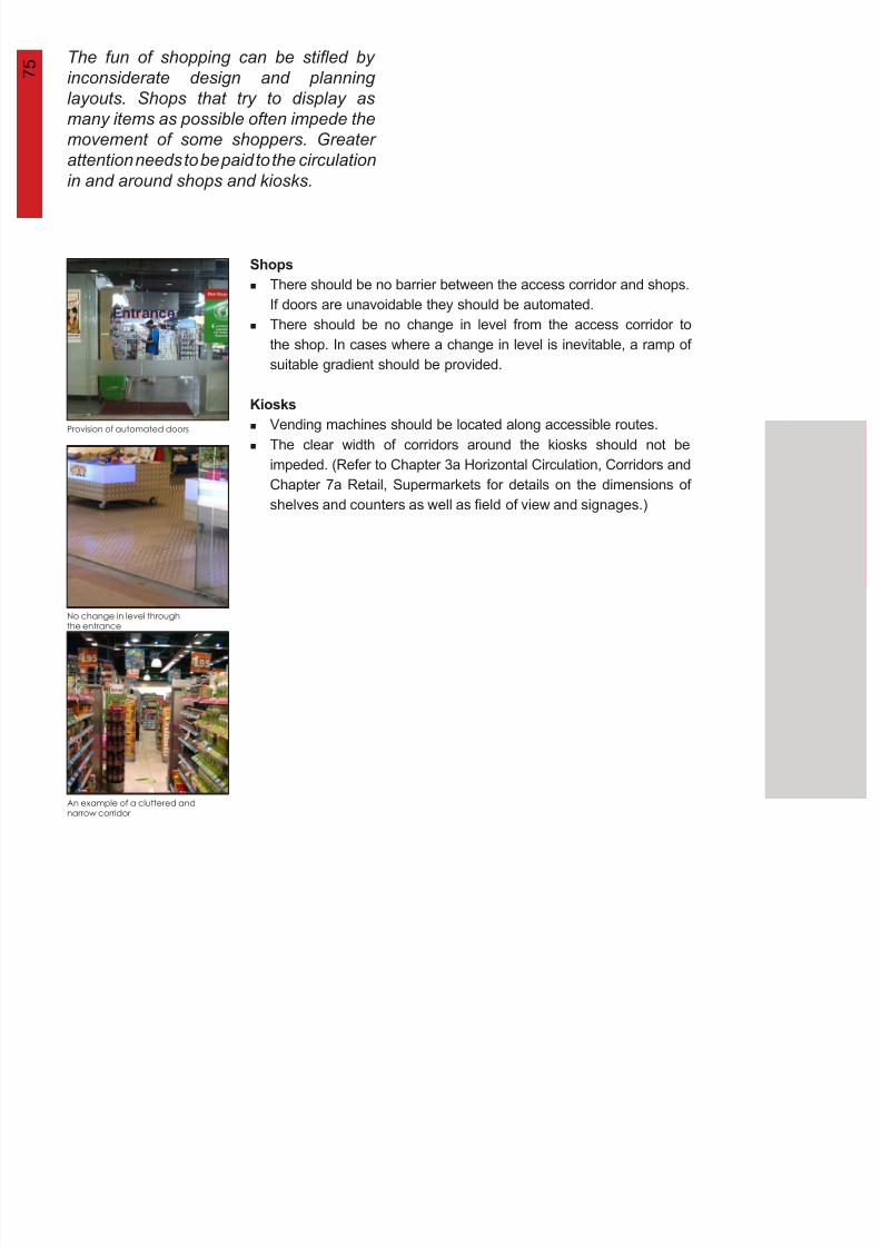
8/12/2019 Universal Design Guidelines
http://slidepdf.com/reader/full/universal-design-guidelines 92/103
in and around shops and kiosks.
Provision of automated doors
No change in level throughthe entrance
An example of a cluttered andnarrow corridor
Shops
Kiosks
There should be no barrier between the access corridor and shops.
If doors are unavoidable they should be automated.
There should be no change in level from the access corridor to
the shop. In cases where a change in level is inevitable, a ramp of
suitable gradient should be provided.
Vending machines should be located along accessible routes.
The clear width of corridors around the kiosks should not be
impeded. (Refer to Chapter 3a Horizontal Circulation, Corridors and
Chapter 7a Retail, Supermarkets for details on the dimensions of
shelves and counters as well as field of view and signages.)
7 6
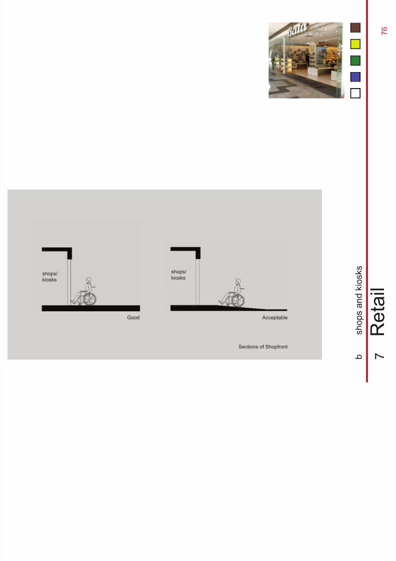
8/12/2019 Universal Design Guidelines
http://slidepdf.com/reader/full/universal-design-guidelines 93/103
Good Acceptable
shops/
kiosks
shops/
kiosks
Sections of Shopfront
7
R e t a i l
b
s h o p s a n
d k i o s
k s
7 7

8/12/2019 Universal Design Guidelines
http://slidepdf.com/reader/full/universal-design-guidelines 94/103
8
F o o d a
n d B e v e r a g e
7 8
7 8
8/12/2019 Universal Design Guidelines
http://slidepdf.com/reader/full/universal-design-guidelines 95/103
7 9
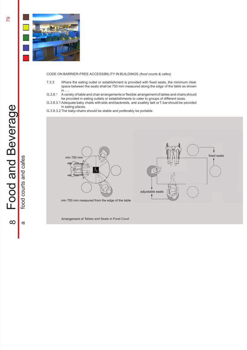
8/12/2019 Universal Design Guidelines
http://slidepdf.com/reader/full/universal-design-guidelines 96/103
Arrangement of Tables and Seats in Food Court
40-50mm dia
adjustable seats
CODE ON BARRIER-FREE ACCESSIBILITY IN BUILDINGS (food courts & cafes)
7.3.3
G.3.8.1
G.3.8.3.1
G.3.8.3.2
8
F o o d a
n d B e v e r a g e
a
f o o
d c o u r t s a n
d c a
f e s
Where the eating outlet or establishment is provided with fixed seats, the minimum clear
space between the seats shall be 750 mm measured along the edge of the table as shown
in . . .
A variety of table and chair arrangements or flexible arrangement of tables and chairs shouldbe provided in eating outlets or establishments to cater to groups of different sizes.
Adequate baby chairs with side and backrests, and a safety belt or T-bar should be provided
in eating places.
The baby-chairs should be stable and preferably be portable.
min 750 mm
min 750 mm measured from the edge of the table
fixed seats
Food and beverage sections are always
major magnets in any commercial or
institutional building. Yet the design
of certain cafes and foodcourts still
unwittingly deny some users the
pleasure of dining in comfort and with
convenience.
8 0
8 0
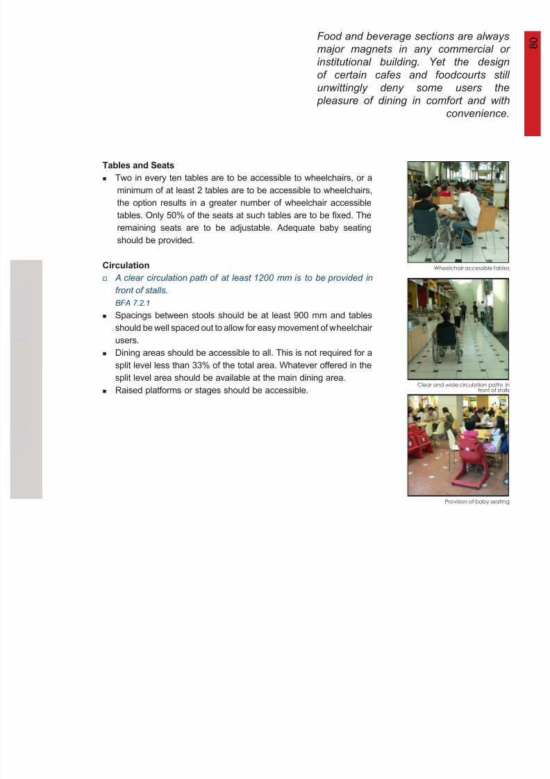
8/12/2019 Universal Design Guidelines
http://slidepdf.com/reader/full/universal-design-guidelines 97/103
Tables and Seats
Circulation
Provision of baby seating
Clear and wide circulation paths infront of stalls
Wheelchair accessible tables
Two in every ten tables are to be accessible to wheelchairs, or a
minimum of at least 2 tables are to be accessible to wheelchairs,
the option results in a greater number of wheelchair accessible
tables. Only 50% of the seats at such tables are to be fixed. The
remaining seats are to be adjustable. Adequate baby seating
should be provided.
A clear circulation path of at least 1200 mm is to be provided in
front of stalls.
BFA 7.2.1
Spacings between stools should be at least 900 mm and tables
should be well spaced out to allow for easy movement of wheelchair
users.
Dining areas should be accessible to all. This is not required for a
split level less than 33% of the total area. Whatever offered in the
split level area should be available at the main dining area.
Raised platforms or stages should be accessible.
8 1
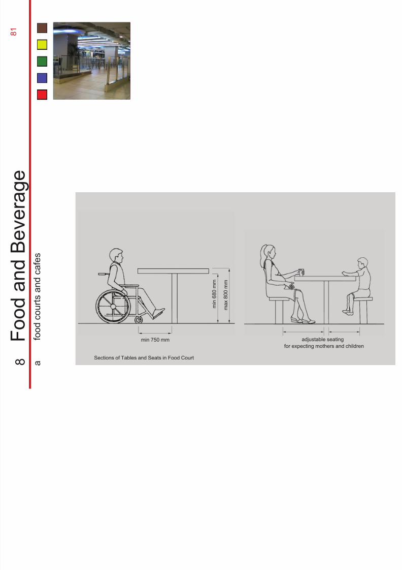
8/12/2019 Universal Design Guidelines
http://slidepdf.com/reader/full/universal-design-guidelines 98/103
min 750 mm
m i n 6 8 0
m m
m a x 8 0 0 m m
adjustable seating
for expecting mothers and children
Sections of Tables and Seats in Food Court
8
F o o d a
n d B e v e r a g e
a
f o o
d c o u r t s a
n d c a
f e s
It is important to ensure that all food
and beverage places are accessible
easily by all through the provision of
appropriate furniture, amenities and
clear circulation paths
8 2
8 2
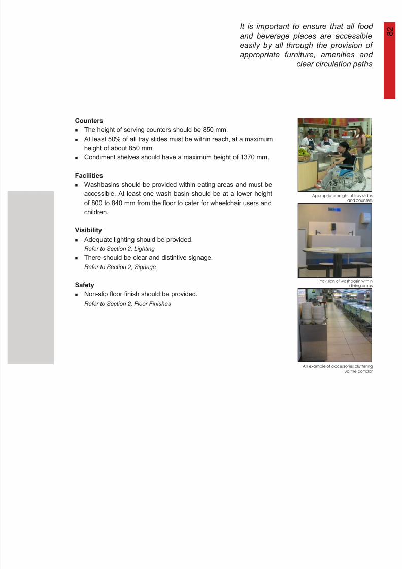
8/12/2019 Universal Design Guidelines
http://slidepdf.com/reader/full/universal-design-guidelines 99/103
Appropriate height of tray slidesand counters
Provision of washbasin withindining areas
Counters
Facilities
Visibility
Safety
An example of accessories clutteringup the corridor
The height of serving counters should be 850 mm.
At least 50% of all tray slides must be within reach, at a maximum
height of about 850 mm.
Condiment shelves should have a maximum height of 1370 mm.
Washbasins should be provided within eating areas and must be
accessible. At least one wash basin should be at a lower height
of 800 to 840 mm from the floor to cater for wheelchair users and
children.
Adequate lighting should be provided.
Refer to Section 2, Lighting
There should be clear and distintive signage.
Refer to Section 2, Signage
Non-slip floor finish should be provided.
Refer to Section 2, Floor Finishes
8 3
8/12/2019 Universal Design Guidelines
http://slidepdf.com/reader/full/universal-design-guidelines 100/103
1.
2.
3.
4.
5.
6.
7.
8.
9.
10.
11.
12.
13.
14.
Architectural Services Department. Universal Accessibility: Best Practices and Guidelines, Hong Kong,
2004.
Building and Construction Authority. Code on Barrier-Free Accessibility In Buildings, Singapore, 2002.
Driskell, David, ed. Design Guide: Universal Access to Outdoor Recreation, PLAE, Inc., Berkeley,
California, USA, 1993.
Goltsman, Susan M., Gilbert, Timothy A. & Wohlford, Steven D. The Accessibility Checklist: An
Evaluation System for Buildings and Outdoor Settings, MIG Communications, Berkeley, California,
USA, 1993.
International Union of Architects & Federation of Architects’ Colleges of the Mexican Republic. Towards
A “Universal Accessibility”: Recommendations for the Development of Public Policies, Spain, 2005.
Levine, Danise, ed. The NYC Guidebook to Accessibility and Universal Design, IDeA Publications,
Buffalo, New York, USA, 2003.
Mace, Ronald L. The Accessible Housing Design File: Barrier Free Environments, John Wiley & Sons,
Inc, USA, 1991.National Environment Agency & Restroom Association. A Guide to Better Public Toilet Design &
Maintenance, Singapore, 2002.
Null, Roberta L. & Cherry, Kenneth F. Universal Design: Creative Solutions for ADA Compliance,
Professional Publications, Inc, Belmont, California, USA, 1998.
Scottish Building Standards Agency. The Building (Scotland) Regulations 2004, Scotland, 2004.
Singapore Civil Defence Force. Code of Practice for Fire Precautions in Building , Singapore, 2002.
Steven Winters Associates. Accessible Housing By Design: Universal Design Principles In Practice,
McGraw-Hill, USA, 1997.
Wilkoff, Wm. L. & Abed, Laura W. Practicing Universal Design: An Interpretation of the ADA, Van
Nostrand Reinhold, New York, USA, 1994.
United States Access Board. Americans with Disabilities Act (ADA), USA, 1990.
R
e f e r e n c e s

8/12/2019 Universal Design Guidelines
http://slidepdf.com/reader/full/universal-design-guidelines 101/103
This Guidebook is produced with the assistance of
the Department of Architecture,School of Design & Environment, National University of Singapore
September 2006
The information contained in this Guidebook is current at the time of printing.
All rights reserved. Reproduction of this Guidebook in whole or part without
permission from BCA is strictly prohibited.
Note
This Guidebook is intended as a guide only. BCA shall not be responsible for any
loss, damage or injury that may be suffered by any person in connection with the
use of the facilities designed based on the recommendation in this Guidebook.

8/12/2019 Universal Design Guidelines
http://slidepdf.com/reader/full/universal-design-guidelines 102/103
Building and Construction Authority, 5 Maxwell Road #16-00, Tower Block MND Complex, Singapore 069110. Tel: 63257720. www.bca.gov.sg

8/12/2019 Universal Design Guidelines
http://slidepdf.com/reader/full/universal-design-guidelines 103/103