Embed Size (px)
Citation preview
www.haaslti.com973-598-1150
LASER PROCESS HEADS • CRASH PROTECTION • ADJUSTABLE MOUNTS • BEAM EXPANDERS/COLLIMATORS • TRANSLATION MOUNTS• KINEMATIC BEAM BENDERS • BEAM SWITCHING UNIT • KINEMATIC BEAM SPLITTER • BEAM SHUTTER/DIODE POINTER • BEAMCOMBINER/DIODE POINTER • SHUTTER INTERLOCK UNITS • POLARIZER HOUSINGS & WAVEPLATES • DELIVERY TUBES • LOCKING
RINGS • BEAM TUBES • ARTICULATED ARMS • COUPLERS • ACCESSORIES • BEZEL ADAPTERS • CO2 LASER NECESSITIES
UUNN IIVVEERRSSAALL LLAASSEERR SSYYSSTTEEMMSS SSEERR II EESS
2
www.haaslti.com • Sales: 973-598-1150
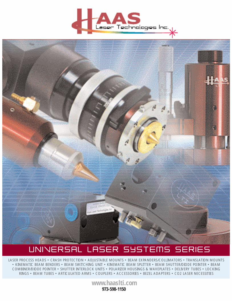
ITEM DESCRIPTION . . . . . . . . . PART REFERENCE NUMBER . . . . . . . . . . . . . PAGELaser Process Heads . . . . . . . . . . . . . . . . . . . . . PHA-19 Series . . . . . . . . . . . . . . . . . . . . . . . . . . 4Micro Machining Laser Process Head Assembly . . CO2 Lasers . . . . . . . . . . . . . . . . . . . . . . . . . . 5-8Crash Detection . . . . . . . . . . . . . . . . . . . . . . . . . . CP-19 Series . . . . . . . . . . . . . . . . . . . . . . . . . . 9Magnetic Breakaway . . . . . . . . . . . . . . . . . . . . . . CB-19 Series . . . . . . . . . . . . . . . . . . . . . . . . . . 10Linear Adjustment Mounts. . . . . . . . . . . . . . . . . . LAM-19 Series . . . . . . . . . . . . . . . . . . . . . . . . . 11Industrial Beam Expander/Collimator . . . . . . . . . . BEC-19 Series . . . . . . . . . . . . . . . . . . . . . . . . . 12Translation Mounts . . . . . . . . . . . . . . . . . . . . . . . . TM-19 Series. . . . . . . . . . . . . . . . . . . . . . . . . 13-14Beam Quality Enhancement System . . . . . . . . . . BQE-25 Series . . . . . . . . . . . . . . . . . . . . . . . . . 15Circular Polarizer System . . . . . . . . . . . . . . . . . . CPU-25 Series . . . . . . . . . . . . . . . . . . . . . . . . . 16Kinematic Beam Benders. . . . . . . . . . . . . . . . . . . BBK-19 Series . . . . . . . . . . . . . . . . . . . . . . . . . 17Safety Shutter with Diode Pointer . . . . . . . . . . . SSDP-19 Series. . . . . . . . . . . . . . . . . . . . . . . . . 18Shutter Interlock Unit . . . . . . . . . . . . . . . . . . . . . SIU-100 Series . . . . . . . . . . . . . . . . . . . . . . . . . 19Laser Beam Dump . . . . . . . . . . . . . . . . . . . . . . . . BD-19 Series . . . . . . . . . . . . . . . . . . . . . . . . . . 20Beam Shutter/Diode Pointer . . . . . . . . . . . . . . . BSDP-19 Series. . . . . . . . . . . . . . . . . . . . . . . . . 21Beam Combiner/Diode Pointer . . . . . . . . . . . . . BCDP-19 Series. . . . . . . . . . . . . . . . . . . . . . . . . 22Beam Switching Unit . . . . . . . . . . . . . . . . . . . . . . BSU-19 Series . . . . . . . . . . . . . . . . . . . . . . . . . 23Kinematic Beam Splitter . . . . . . . . . . . . . . . . . . . BSK-29 Series . . . . . . . . . . . . . . . . . . . . . . . . . 24Industrial Articulated Arm . . . . . . . . . . . . . . . . . . ARM-19 Series . . . . . . . . . . . . . . . . . . . . . . . . . 25“Quick Mount” Beam Delivery . . . . . . . . . . . . . . BTQ-19 Series . . . . . . . . . . . . . . . . . . . . . . . . . 26(Tubes/Couplers)Beam Tubes & Locking Rings. . . . . . . . . . . . . . . . BTA-19 Series . . . . . . . . . . . . . . . . . . . . . . . . . 27Telescopic Beam Tubes . . . . . . . . . . . . . . . . . . . . BTT-19 Series. . . . . . . . . . . . . . . . . . . . . . . . . . 28Telescopic Bellow Beam Tubes . . . . . . . . . . . . . . BTB-19 Series . . . . . . . . . . . . . . . . . . . . . . . . . 29
19mm SERIES ACCESSORIES:Beam Bender/Alignment Target. . . . . . . . . . . . . . . TGT-BBK-19 . . . . . . . . . . . . . . . . . . . . . . . . . . 30C-Mount Alignment Target . . . . . . . . . . . . . . . . . . . TGT-CMNT. . . . . . . . . . . . . . . . . . . . . . . . . . . 30Optic Wrench . . . . . . . . . . . . . . . . . . . . . . . . . . . . OW-110-092 . . . . . . . . . . . . . . . . . . . . . . . . . . 30Alignment Cards . . . . . . . . . . . . . . . . . . . . . . . . . . . . AC-100 . . . . . . . . . . . . . . . . . . . . . . . . . . . . 31Optic Cleaning Kit . . . . . . . . . . . . . . . . . . . . . . . . . . . OCK-50 . . . . . . . . . . . . . . . . . . . . . . . . . . . . 31
19mm LASER BEZEL ADAPTERS:19mm Laser Bezel Adapters . . . . . . . . . . . . . . . . . . . . . . . . . . . . . . . . . . . . . . . . . . . . . . . . . . . . . 32
Universal Series Quick-Reference Part Number Listing . . . . . . . . . . . . . . . . . . . . . . . . . . . . . . . . . 33
UUNN IIVVEERRSSAALL LLAASSEERR SSYYSSTTEEMMSS
INDEX
3
www.haaslti.com • Sales: 973-598-1150
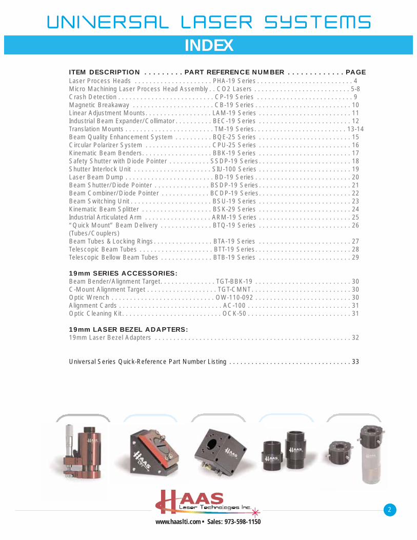
Safety ShuttersBeam QualityEnhancer
*Note: Scale varies between drawings.
Low Pow
er Laser Series
Circular Polarizers
Beam Tubes
Targets/Optic Wrenches
BeamSplitters
Beam Benders BeamSwitchesLinear
Adjustable Mounts
Crash Protection/Detection Trepan
HeadsLaserHead
ScanHeads
Wrists
Beam Expanders Diode Pointers
Laser BezelAdapters
1199mmmm SSEERR IIEESS SSYYSSTTEEMM DD IIAAGGRRAAMM
4
www.haaslti.com • Sales: 973-598-1150
Low
Pow
er L
aser
Ser
ies
Specifications subject to change without notice.Consult Haas Laser Technologies for Details.
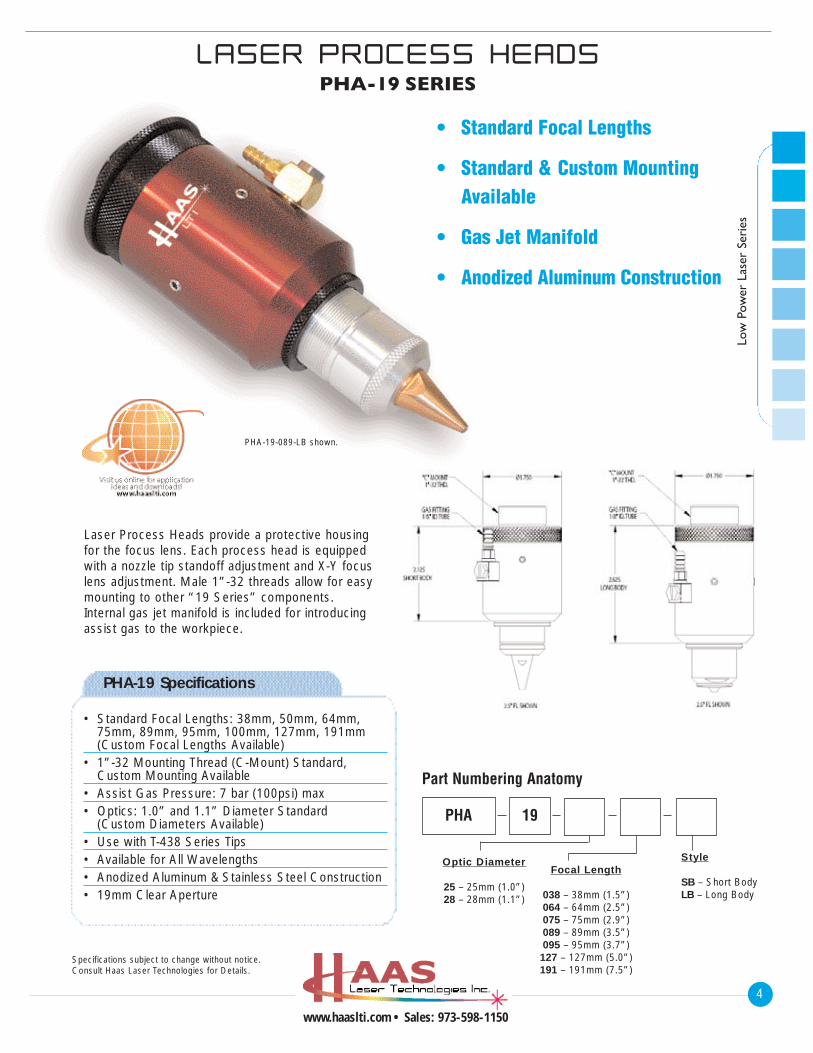
LLAASSEERR PPRROOCCEESSSS HHEEAADDSSPHA-19 SERIES
• Standard Focal Lengths
• Standard & Custom Mounting Available
• Gas Jet Manifold
• Anodized Aluminum Construction
Laser Process Heads provide a protective housingfor the focus lens. Each process head is equippedwith a nozzle tip standoff adjustment and X-Y focuslens adjustment. Male 1”-32 threads allow for easymounting to other “19 Series” components.Internal gas jet manifold is included for introducingassist gas to the workpiece.
PHA-19-089-LB shown.
PHA-19 Specifications
• Standard Focal Lengths: 38mm, 50mm, 64mm, 75mm, 89mm, 95mm, 100mm, 127mm, 191mm (Custom Focal Lengths Available)
• 1”-32 Mounting Thread (C-Mount) Standard, Custom Mounting Available
• Assist Gas Pressure: 7 bar (100psi) max• Optics: 1.0” and 1.1” Diameter Standard
(Custom Diameters Available)• Use with T-438 Series Tips• Available for All Wavelengths• Anodized Aluminum & Stainless Steel Construction• 19mm Clear Aperture
Optic Diameter
25 – 25mm (1.0”)28 – 28mm (1.1”)
Focal Length
038 – 38mm (1.5”)064 – 64mm (2.5”)075 – 75mm (2.9”)089 – 89mm (3.5”)095 – 95mm (3.7”)127 – 127mm (5.0”)191 – 191mm (7.5”)
Style
SB – Short BodyLB – Long Body
PHA
Part Numbering Anatomy
19
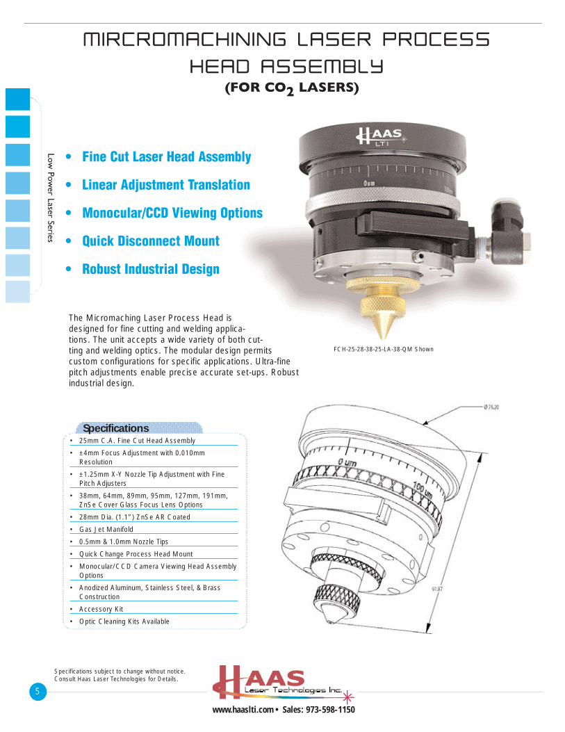
MMIIRRCCRROOMMAACCHH IINN IINNGG LLAASSEERR PPRROOCCEESSSS
HHEEAADD AASSSSEEMMBBLLYY(FOR CO2 LASERS)
5
www.haaslti.com • Sales: 973-598-1150
Low Pow
er Laser Series
Specifications subject to change without notice.Consult Haas Laser Technologies for Details.
• Fine Cut Laser Head Assembly
• Linear Adjustment Translation
• Monocular/CCD Viewing Options
• Quick Disconnect Mount
• Robust Industrial Design
The Micromaching Laser Process Head isdesigned for fine cutting and welding applica-tions. The unit accepts a wide variety of both cut-ting and welding optics. The modular design permitscustom configurations for specific applications. Ultra-finepitch adjustments enable precise accurate set-ups. Robustindustrial design.
FCH-25-28-38-25-LA-38-QM Shown
Specifications• 25mm C.A. Fine Cut Head Assembly
• ±4mm Focus Adjustment with 0.010mm Resolution
• ±1.25mm X-Y Nozzle Tip Adjustment with Fine Pitch Adjusters
• 38mm, 64mm, 89mm, 95mm, 127mm, 191mm, ZnSe Cover Glass Focus Lens Options
• 28mm Dia. (1.1”) ZnSe AR Coated
• Gas Jet Manifold
• 0.5mm & 1.0mm Nozzle Tips
• Quick Change Process Head Mount
• Monocular/CCD Camera Viewing Head AssemblyOptions
• Anodized Aluminum, Stainless Steel, & Brass Construction
• Accessory Kit
• Optic Cleaning Kits Available
6
www.haaslti.com • Sales: 973-598-1150
Low
Pow
er L
aser
Ser
ies
Specifications subject to change without notice.Consult Haas Laser Technologies for Details.
FOCUSING OPTICS
210CV-25030-038-ZS-DAR: ZnSe CO2 Focus Lens 38mm (1.5”) F.L x 25mm (1.0”) Diameter
210CV-28020-063-ZS-SCO: ZnSe CO2 Focus Lens 63mm (2.5”)F.L x 28mm (1.1”) Diameter
210CV-28040-89-ZS-DAR: ZnSe CO2 Focus Lens 89mm (3.5”) F.L x 28mm (1.1”) Diameter
210CV-28030-095-ZS-DAR: ZnSe CO2 Focus Lens 95mm (3.75”) F.L x 28mm (1.1”) Diameter
210CV-28040-127-ZS-SCO: ZnSe CO2 Focus Lens 127mm (5.0”) F.L x 28mm (1.1”) Diameter
210CV-28030-191-ZS-SCO: ZnSe CO2 Focus Lens 191mm (7.5”) F.L x 28mm (1.1”) Diameter
CUTTING & WELDING
COVER GLASS
210CC-25010-XXX-ZS-DAR: ZnSe CO2 Cover Glass 25mm (1.0”) Diameter
210CC-28010-XXX-ZS-DAR: ZnSe CO2 Cover Glass 28mm (1.1”) Diameter
NOZZLE TIPS
T-512-020-H01: 0.5mm Nozzle Tip (Cutting)T-512-040-H01: 1.0mm Nozzle Tip (Cutting)
T-512-080-H01: 2.0mm Nozzle Tip (Welding)T-512-120-H01: 3.0mm Nozzle Tip (Welding)T-512-160-H01: 4.0mm Nozzle Tip (Welding)
CUTTING: WELDING:
FCH-25-038-NE: Nozzle Extension for 38mm (1.5”) Focus Lens
FCH-25-063-NE: Nozzle Extension for 63mm (2.5”) Focus Lens
FCH-25-089-NE: Nozzle Extension for 89mm (3.5”) Focus Lens
FCH-25-095-NE: Nozzle Extension for 95mm (3.75”) Focus Lens
FCH-25-127-NE: Nozzle Extension for 127mm (5.0”) Focus Lens
FCH-25-191-NE: Nozzle Extension for 191mm (7.5”) Focus Lens
FCH-25-ACC-CO2: Fine Cut Head Accessory Kit.Includes Optic Wrench, Target, & CO2 Alignment Paper.
OCK-50: Optic Cleaning Kit
OPTIONS ACCESSORIESNOZZLE EXTENSIONS
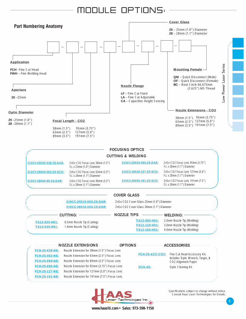
MMOODDUULLEE OOPPTT IIOONNSS::
Mounting Female
QM – Quick Disconnect (Male)OF – Quick Disconnect (Female)BC – Bout Circle 66.675mm
(2.625”) M5 ThreadNozzle Flange
LF – Fine Cut FixedLA – Fine Cut AdjustableCA – Capacitive Height Sensing
Cover Glass
25 – 25mm (1.0”) Diameter28 – 28mm (1.1”) Diameter
Nozzle Extensions - CO2
38mm (1.5”)63mm (2.5”)89mm (3.5”)
Optic Diameter
25 –25mm (1.0”)28 –28mm (1.1”)
Focal Length - CO2
38mm (1.5”)63mm (2.5”)89mm (3.5”)
95mm (3.75”)127mm (5.0”)191mm (7.5”)
Aperture
25 –25mm
Application
FCH –Fine Cut HeadFWH – Fine Welding Head
Part Numbering Anatomy
95mm (3.75”)127mm (5.0”)191mm (7.5”)
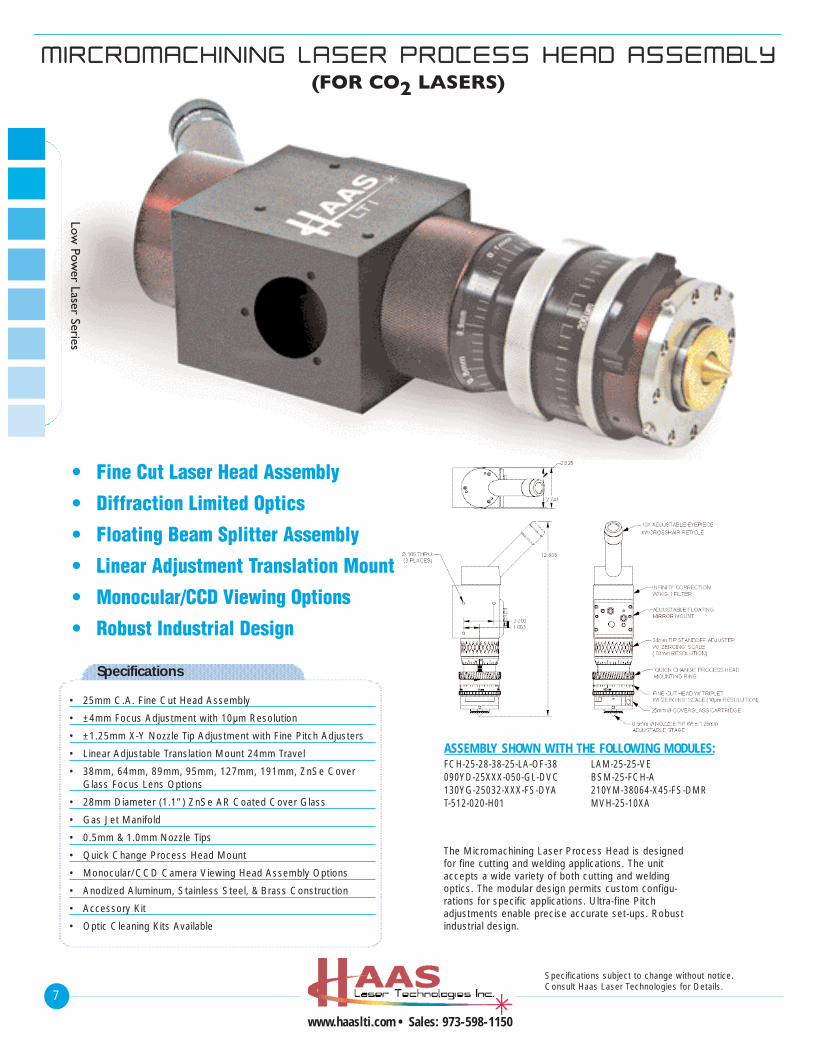
MMIIRRCCRROOMMAACCHH IINN IINNGG LLAASSEERR PPRROOCCEESSSS HHEEAADD AASSSSEEMMBBLLYY
(FOR CO2 LASERS)
7
www.haaslti.com • Sales: 973-598-1150
Specifications subject to change without notice.Consult Haas Laser Technologies for Details.
Low Pow
er Laser Series
Specifications
• 25mm C.A. Fine Cut Head Assembly
• ±4mm Focus Adjustment with 10µm Resolution
• ±1.25mm X-Y Nozzle Tip Adjustment with Fine Pitch Adjusters
• Linear Adjustable Translation Mount 24mm Travel
• 38mm, 64mm, 89mm, 95mm, 127mm, 191mm, ZnSe Cover Glass Focus Lens Options
• 28mm Diameter (1.1”) ZnSe AR Coated Cover Glass
• Gas Jet Manifold
• 0.5mm & 1.0mm Nozzle Tips
• Quick Change Process Head Mount
• Monocular/CCD Camera Viewing Head Assembly Options
• Anodized Aluminum, Stainless Steel, & Brass Construction
• Accessory Kit
• Optic Cleaning Kits Available
• Fine Cut Laser Head Assembly
• Diffraction Limited Optics
• Floating Beam Splitter Assembly
• Linear Adjustment Translation Mount
• Monocular/CCD Viewing Options
• Robust Industrial Design
The Micromachining Laser Process Head is designedfor fine cutting and welding applications. The unitaccepts a wide variety of both cutting and weldingoptics. The modular design permits custom configu-rations for specific applications. Ultra-fine Pitchadjustments enable precise accurate set-ups. Robustindustrial design.
ASSEMBLY SHOWN WITH THE FOLLOWING MODULES:FCH-25-28-38-25-LA-OF-38090YD-25XXX-050-GL-DVC130YG-25032-XXX-FS-DYAT-512-020-H01
LAM-25-25-VEBSM-25-FCH-A210YM-38064-X45-FS-DMRMVH-25-10XA
8
www.haaslti.com • Sales: 973-598-1150
Specifications subject to change without notice.Consult Haas Laser Technologies for Details.
Low
Pow
er L
aser
Ser
ies
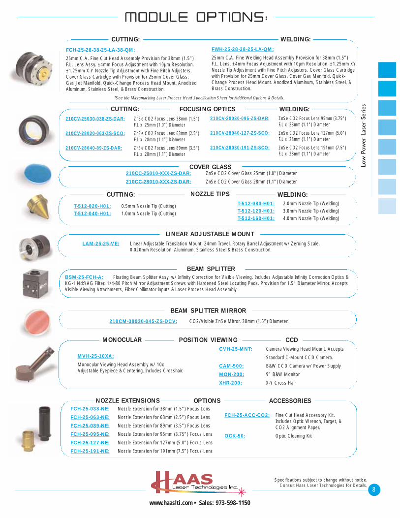
FCH-25-28-38-25-LA-38-QM:
25mm C.A. Fine Cut Head Assembly Provision for 38mm (1.5”)F.L. Lens Assy. ±4mm Focus Adjustment with 10µm Resolution.±1.25mm X-Y Nozzle Tip Adjustment with Fine Pitch Adjusters.Cover Glass Cartridge with Provision for 25mm Cover Glass. Gas Jet Manifold. Quick-Change Process Head Mount. AnodizedAluminum, Stainless Steel, & Brass Construction.
FWH-25-28-38-25-LA-QM:
25mm C.A. Fine Welding Head Assembly Provision for 38mm (1.5”) F.L. Lens. ±4mm Focus Adjustment with 10µm Resolution. ±1.25mm XYNozzle Tip Adjustment with Fine Pitch Adjusters. Cover Glass Cartridgewith Provision for 25mm Cover Glass. Cover Gas Manifold. Quick-Change Process Head Mount. Anodized Aluminum, Stainless Steel, &Brass Construction.
FOCUSING OPTICSCUTTING:
CUTTING:
WELDING:
WELDING:
NOZZLE TIPS
T-512-020-H01: 0.5mm Nozzle Tip (Cutting)T-512-040-H01: 1.0mm Nozzle Tip (Cutting)
T-512-080-H01: 2.0mm Nozzle Tip (Welding)T-512-120-H01: 3.0mm Nozzle Tip (Welding)T-512-160-H01: 4.0mm Nozzle Tip (Welding)
CUTTING: WELDING:
COVER GLASS
LINEAR ADJUSTABLE MOUNTLAM-25-25-VE: Linear Adjustable Translation Mount. 24mm Travel. Rotary Barrel Adjustment w/ Zeroing Scale.
0.020mm Resolution. Aluminum, Stainless Steel & Brass Construction.
BEAM SPLITTERBSM-25-FCH-A: Floating Beam Splitter Assy. w/ Infinity Correction for Visible Viewing. Includes Adjustable Infinity Correction Optics &KG-1 Nd:YAG Filter. 1/4-80 Pitch Mirror Adjustment Screws with Hardened Steel Locating Pads. Provision for 1.5” Diameter Mirror. AcceptsVisible Viewing Attachments, Fiber Collimator Inputs & Laser Process Head Assembly.
BEAM SPLITTER MIRROR
210CM-38030-045-ZS-DCV: CO2/Visible ZnSe Mirror. 38mm (1.5”) Diameter.
POSITION VIEWING
MVH-25-10XA:
Monocular Viewing Head Assembly w/ 10xAdjustable Eyepiece & Centering. Includes Crosshair.
CVH-25-MNT: Camera Viewing Head Mount. Accepts
Standard C-Mount CCD Camera.
CAM-500: B&W CCD Camera w/ Power Supply
MON-200: 9” B&W Monitor
XHR-200: X-Y Cross Hair
MONOCULAR CCD
OPTIONS ACCESSORIESNOZZLE EXTENSIONS
MMOODDUULLEE OOPPTT IIOONNSS::
*See the Micromaching Laser Process Head Specification Sheet for Additional Options & Details.
FCH-25-038-NE: Nozzle Extension for 38mm (1.5”) Focus Lens
FCH-25-063-NE: Nozzle Extension for 63mm (2.5”) Focus Lens
FCH-25-089-NE: Nozzle Extension for 89mm (3.5”) Focus Lens
FCH-25-095-NE: Nozzle Extension for 95mm (3.75”) Focus Lens
FCH-25-127-NE: Nozzle Extension for 127mm (5.0”) Focus Lens
FCH-25-191-NE: Nozzle Extension for 191mm (7.5”) Focus Lens
FCH-25-ACC-CO2: Fine Cut Head Accessory Kit.Includes Optic Wrench, Target, & CO2 Alignment Paper.
OCK-50: Optic Cleaning Kit
210CV-25030-038-ZS-DAR: ZnSe CO2 Focus Lens 38mm (1.5”) F.L x 25mm (1.0”) Diameter
210CV-28020-063-ZS-SCO: ZnSe CO2 Focus Lens 63mm (2.5”) F.L x 28mm (1.1”) Diameter
210CV-28040-89-ZS-DAR: ZnSe CO2 Focus Lens 89mm (3.5”) F.L x 28mm (1.1”) Diameter
210CV-28030-095-ZS-DAR: ZnSe CO2 Focus Lens 95mm (3.75”) F.L x 28mm (1.1”) Diameter
210CV-28040-127-ZS-SCO: ZnSe CO2 Focus Lens 127mm (5.0”) F.L x 28mm (1.1”) Diameter
210CV-28030-191-ZS-SCO: ZnSe CO2 Focus Lens 191mm (7.5”) F.L x 28mm (1.1”) Diameter
210CC-25010-XXX-ZS-DAR: ZnSe CO2 Cover Glass 25mm (1.0”) Diameter
210CC-28010-XXX-ZS-DAR: ZnSe CO2 Cover Glass 28mm (1.1”) Diameter
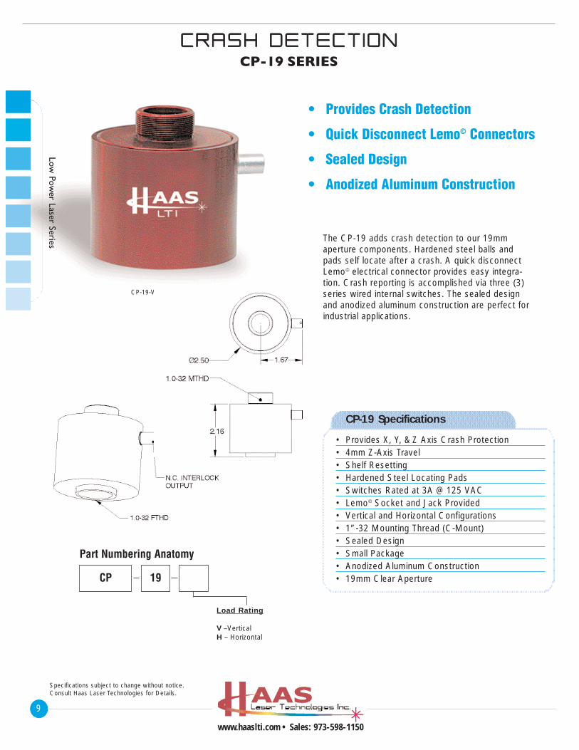
CP-19-V shown.
CCRRAASSHH DDEETTEECCTT IIOONNCP-19 SERIES
9
www.haaslti.com • Sales: 973-598-1150
Specifications subject to change without notice.Consult Haas Laser Technologies for Details.
Low Pow
er Laser Series
CP-19 Specifications
• Provides X, Y, & Z Axis Crash Protection• 4mm Z-Axis Travel• Shelf Resetting• Hardened Steel Locating Pads• Switches Rated at 3A @ 125 VAC• Lemo© Socket and Jack Provided• Vertical and Horizontal Configurations• 1”-32 Mounting Thread (C-Mount)• Sealed Design• Small Package• Anodized Aluminum Construction• 19mm Clear Aperture
Load Rating
V –VerticalH – Horizontal
CP 19
Part Numbering Anatomy
The CP-19 adds crash detection to our 19mmaperture components. Hardened steel balls andpads self locate after a crash. A quick disconnectLemo© electrical connector provides easy integra-tion. Crash reporting is accomplished via three (3)series wired internal switches. The sealed designand anodized aluminum construction are perfect forindustrial applications.
• Provides Crash Detection
• Quick Disconnect Lemo© Connectors
• Sealed Design
• Anodized Aluminum Construction
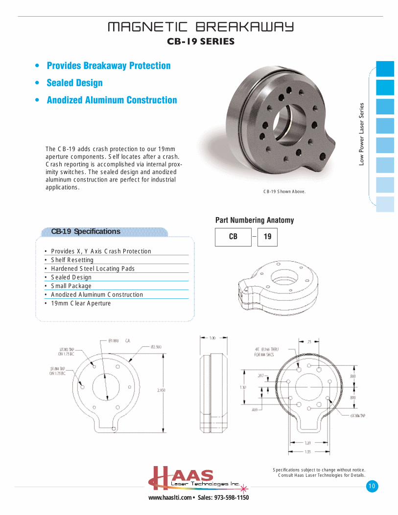
CB-19 Shown Above.
10
www.haaslti.com • Sales: 973-598-1150
Low
Pow
er L
aser
Ser
ies
MMAAGGNNEETT IICC BBRREEAAKKAAWWAAYYCB-19 SERIES
Specifications subject to change without notice.Consult Haas Laser Technologies for Details.
CB-19 Specifications
• Provides X, Y Axis Crash Protection• Shelf Resetting• Hardened Steel Locating Pads• Sealed Design• Small Package• Anodized Aluminum Construction• 19mm Clear Aperture
The CB-19 adds crash protection to our 19mmaperture components. Self locates after a crash.Crash reporting is accomplished via internal prox-imity switches. The sealed design and anodizedaluminum construction are perfect for industrialapplications.
• Provides Breakaway Protection
• Sealed Design
• Anodized Aluminum Construction
CB 19
Part Numbering Anatomy
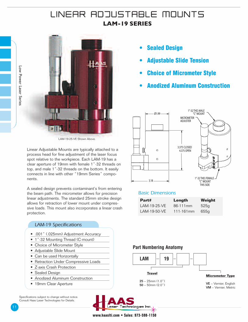
LAM-19-25-VE Shown Above.
LL IINNEEAARR AADDJJUUSSTTAABBLLEE MMOOUUNNTTSSLAM-19 SERIES
11
www.haaslti.com • Sales: 973-598-1150
Specifications subject to change without notice.Consult Haas Laser Technologies for Details.
Low Pow
er Laser Series
Part# Length WeightLAM-19-25-VE 86-111mm 525gLAM-19-50-VE 111-161mm 655g
• Sealed Design
• Adjustable Slide Tension
• Choice of Micrometer Style
• Anodized Aluminum Construction
Linear Adjustable Mounts are typically attached to aprocess head for fine adjustment of the laser focusspot relative to the workpiece. Each LAM-19 has aclear aperture of 19mm with female 1”-32 threads ontop, and male 1”-32 threads on the bottom. It easilyconnects in line with other “19mm Series” compo-nents.
A sealed design prevents contaminant's from enteringthe beam path. The micrometer allows for precisionlinear adjustments. The standard 25mm stroke designallows for retraction of lower mount under compres-sive loads. This mount also incorporates a linear crashprotection.
Basic Dimensions
LAM-19 Specifications
• .001” (.025mm) Adjustment Accuracy• 1”-32 Mounting Thread (C-mount)• Choice of Micrometer Style• Adjustable Slide Mount• Can be used Horizontally• Retraction Under Compressive Loads• Z-axis Crash Protection• Sealed Design• Anodized Aluminum Construction• 19mm Clear Aperture
Travel
25 – 25mm (1.0”)50 – 50mm (2.0”)
Micrometer Type
VE – Vernier, EnglishVM – Vernier, Metric
LAM
Part Numbering Anatomy
19
4.375 OPEN3.375 CLOSED
Ø1.99
3.18
MICROMETERADJUSTER
1"-32 THD. MALE"C" MOUNT
1"-32 THD. FEMALE"C" MOUNTTHIS SIDE
12
www.haaslti.com • Sales: 973-598-1150
Low
Pow
er L
aser
Ser
ies
Specifications subject to change without notice.Consult Haas Laser Technologies for Details.
IINNDDUUSSTTRR IIAALL BBEEAAMM
EEXXPPAANNDDEERR//CCOOLLLL IIMMAATTOORRBEC-19 SERIES
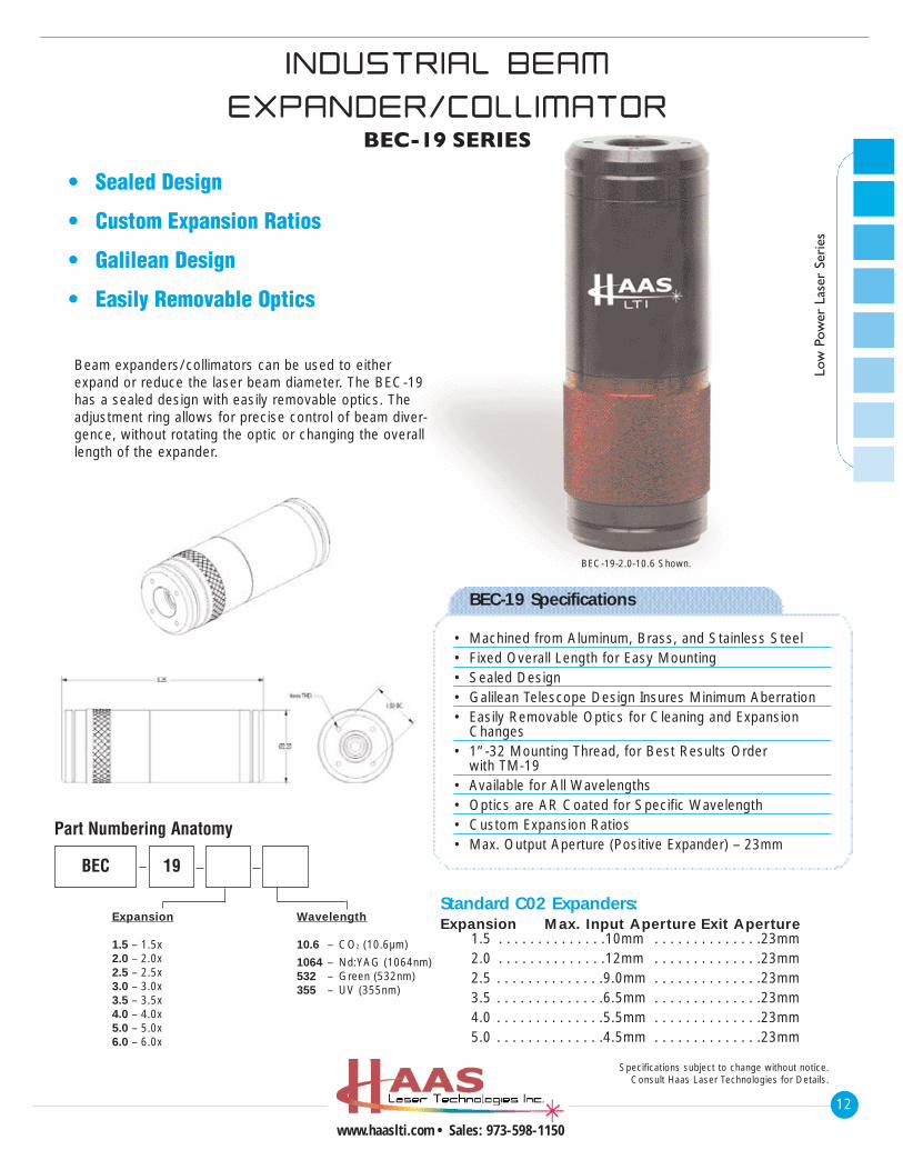
BEC-19-2.0-10.6 Shown.
Beam expanders/collimators can be used to eitherexpand or reduce the laser beam diameter. The BEC-19has a sealed design with easily removable optics. Theadjustment ring allows for precise control of beam diver-gence, without rotating the optic or changing the overalllength of the expander.
• Sealed Design
• Custom Expansion Ratios
• Galilean Design
• Easily Removable Optics
Expansion
1.5 – 1.5x2.0 – 2.0x2.5 – 2.5x3.0 – 3.0x3.5 – 3.5x4.0 – 4.0x5.0 – 5.0x6.0 – 6.0x
Wavelength
10.6 – CO2 (10.6µm)
1064 – Nd:YAG (1064nm)532 – Green (532nm)355 – UV (355nm)
BEC 19
Part Numbering Anatomy
Standard C02 Expanders:Expansion Max. Input Aperture Exit Aperture
1.5 . . . . . . . . . . . . . .10mm . . . . . . . . . . . . . .23mm2.0 . . . . . . . . . . . . . .12mm . . . . . . . . . . . . . .23mm2.5 . . . . . . . . . . . . . .9.0mm . . . . . . . . . . . . . .23mm3.5 . . . . . . . . . . . . . .6.5mm . . . . . . . . . . . . . .23mm4.0 . . . . . . . . . . . . . .5.5mm . . . . . . . . . . . . . .23mm5.0 . . . . . . . . . . . . . .4.5mm . . . . . . . . . . . . . .23mm
BEC-19 Specifications
• Machined from Aluminum, Brass, and Stainless Steel• Fixed Overall Length for Easy Mounting• Sealed Design• Galilean Telescope Design Insures Minimum Aberration• Easily Removable Optics for Cleaning and Expansion
Changes• 1”-32 Mounting Thread, for Best Results Order
with TM-19• Available for All Wavelengths• Optics are AR Coated for Specific Wavelength• Custom Expansion Ratios• Max. Output Aperture (Positive Expander) – 23mm
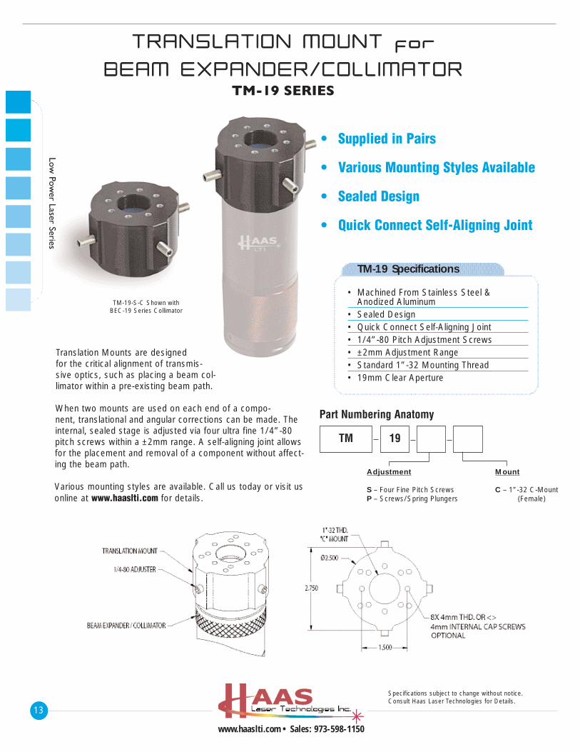
TM-19 Specifications
• Machined From Stainless Steel & Anodized Aluminum
• Sealed Design• Quick Connect Self-Aligning Joint• 1/4”-80 Pitch Adjustment Screws• ±2mm Adjustment Range• Standard 1”-32 Mounting Thread• 19mm Clear Aperture
Adjustment
S – Four Fine Pitch ScrewsP – Screws/Spring Plungers
Mount
C – 1”-32 C-Mount(Female)
TM 19
Part Numbering Anatomy
• Supplied in Pairs
• Various Mounting Styles Available
• Sealed Design
• Quick Connect Self-Aligning Joint
Translation Mounts are designedfor the critical alignment of transmis-sive optics, such as placing a beam col-limator within a pre-existing beam path.
When two mounts are used on each end of a compo-nent, translational and angular corrections can be made. Theinternal, sealed stage is adjusted via four ultra fine 1/4”-80pitch screws within a ±2mm range. A self-aligning joint allowsfor the placement and removal of a component without affect-ing the beam path.
Various mounting styles are available. Call us today or visit usonline at www.haaslti.com for details.
TM-19-S-C Shown withBEC-19 Series Collimator
13
www.haaslti.com • Sales: 973-598-1150
Specifications subject to change without notice.Consult Haas Laser Technologies for Details.
Low Pow
er Laser Series
TTRRAANNSSLLAATT IIOONN MMOOUUNNTT ffoorr
BBEEAAMM EEXXPPAANNDDEERR//CCOOLLLL IIMMAATTOORRTM-19 SERIES
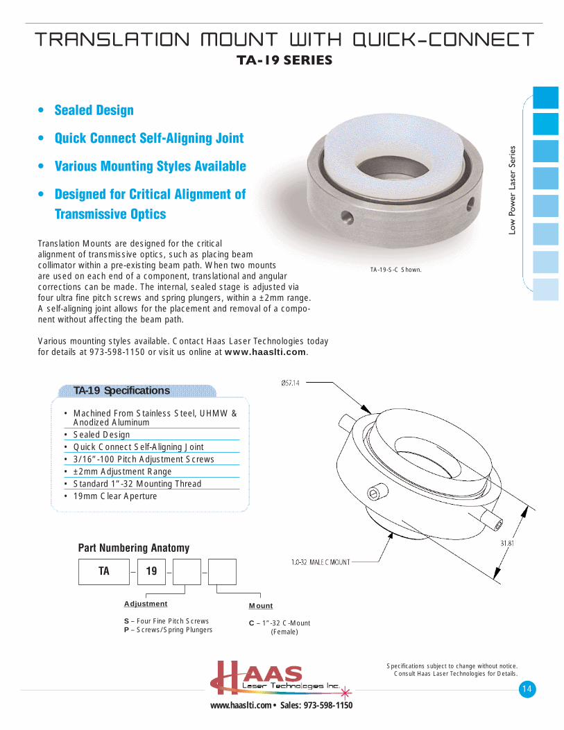
TA-19 Specifications
• Machined From Stainless Steel, UHMW & Anodized Aluminum
• Sealed Design• Quick Connect Self-Aligning Joint• 3/16”-100 Pitch Adjustment Screws• ±2mm Adjustment Range• Standard 1”-32 Mounting Thread• 19mm Clear Aperture
Adjustment
S – Four Fine Pitch ScrewsP – Screws/Spring Plungers
Mount
C – 1”-32 C-Mount(Female)
TA 19
Part Numbering Anatomy
• Sealed Design
• Quick Connect Self-Aligning Joint
• Various Mounting Styles Available
• Designed for Critical Alignment of Transmissive Optics
TA-19-S-C Shown.
14
www.haaslti.com • Sales: 973-598-1150
Low
Pow
er L
aser
Ser
ies
Specifications subject to change without notice.Consult Haas Laser Technologies for Details.
TTRRAANNSSLLAATT IIOONN MMOOUUNNTT WWIITTHH QQUU IICCKK--CCOONNNNEECCTTTA-19 SERIES
Translation Mounts are designed for the criticalalignment of transmissive optics, such as placing beamcollimator within a pre-existing beam path. When two mountsare used on each end of a component, translational and angularcorrections can be made. The internal, sealed stage is adjusted viafour ultra fine pitch screws and spring plungers, within a ±2mm range.A self-aligning joint allows for the placement and removal of a compo-nent without affecting the beam path.
Various mounting styles available. Contact Haas Laser Technologies todayfor details at 973-598-1150 or visit us online at www.haaslti.com.
BBEEAAMM QQUUAALL IITTYY
EENNHHAANNCCEEMMEENNTT SSYYSSTTEEMMBQE-25 SERIES
15
www.haaslti.com • Sales: 973-598-1150
Specifications subject to change without notice.Consult Haas Laser Technologies for Details.
Low Pow
er Laser Series
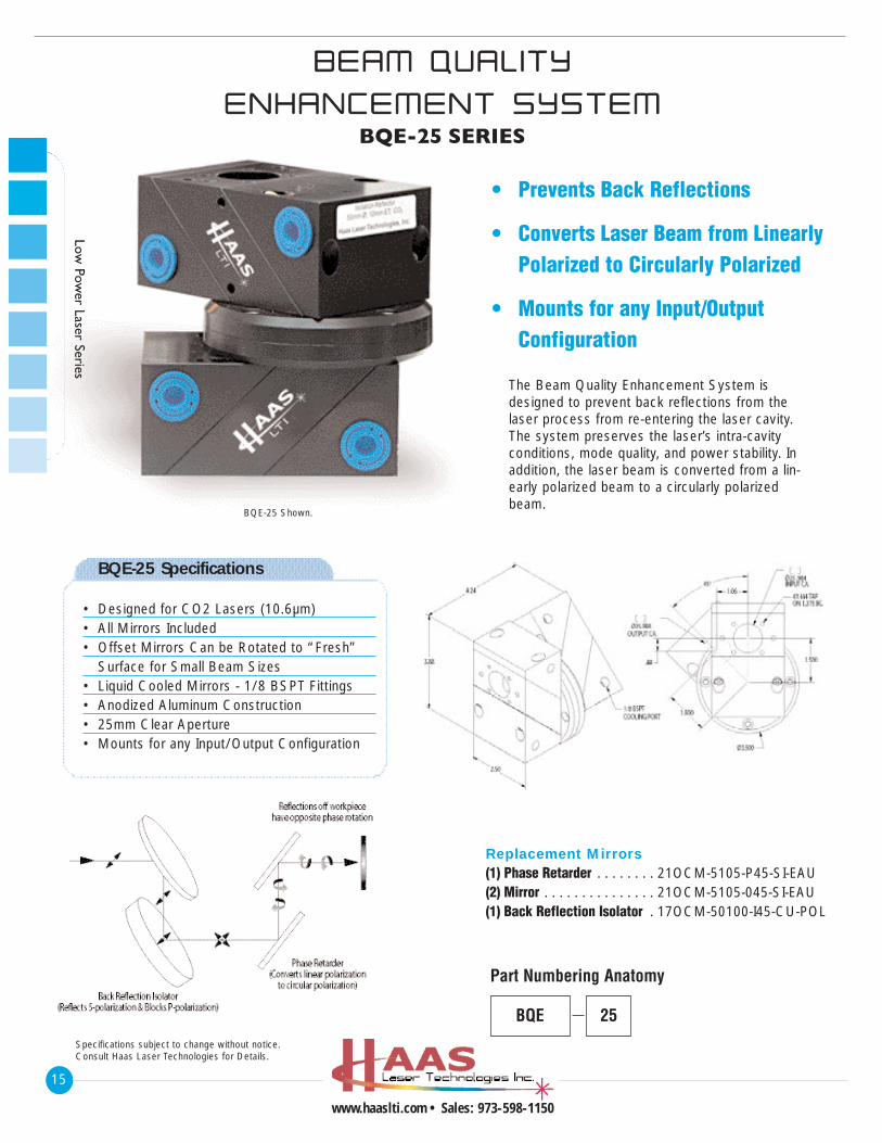
• Prevents Back Reflections
• Converts Laser Beam from Linearly Polarized to Circularly Polarized
• Mounts for any Input/Output Configuration
The Beam Quality Enhancement System isdesigned to prevent back reflections from thelaser process from re-entering the laser cavity.The system preserves the laser’s intra-cavityconditions, mode quality, and power stability. Inaddition, the laser beam is converted from a lin-early polarized beam to a circularly polarizedbeam.
Replacement Mirrors(1) Phase Retarder . . . . . . . . 21OCM-5105-P45-SI-EAU(2) Mirror . . . . . . . . . . . . . . . 21OCM-5105-045-SI-EAU(1) Back Reflection Isolator . 17OCM-50100-I45-CU-POL
BQE-25 Specifications
• Designed for CO2 Lasers (10.6µm)• All Mirrors Included• Offset Mirrors Can be Rotated to “Fresh”
Surface for Small Beam Sizes• Liquid Cooled Mirrors - 1/8 BSPT Fittings• Anodized Aluminum Construction• 25mm Clear Aperture• Mounts for any Input/Output Configuration
BQE
Part Numbering Anatomy
25
BQE-25 Shown.
16
www.haaslti.com • Sales: 973-598-1150
Low
Pow
er L
aser
Ser
ies
CC IIRRCCUULLAARR PPOOLLAARR IIZZEERR SSYYSSTTEEMMCPU-25 SERIES
Specifications subject to change without notice.Consult Haas Laser Technologies for Details.
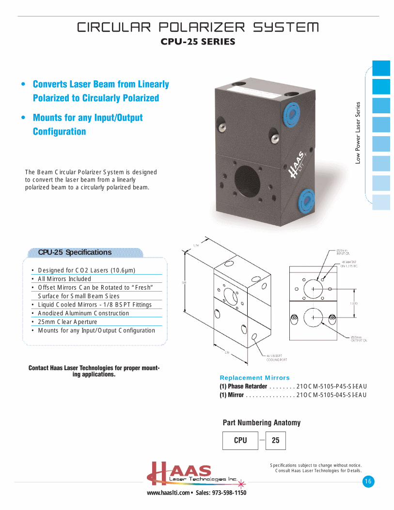
• Converts Laser Beam from Linearly Polarized to Circularly Polarized
• Mounts for any Input/Output Configuration
The Beam Circular Polarizer System is designedto convert the laser beam from a linearly polarized beam to a circularly polarized beam.
Replacement Mirrors(1) Phase Retarder . . . . . . . . 21OCM-5105-P45-SI-EAU(1) Mirror . . . . . . . . . . . . . . . 21OCM-5105-045-SI-EAU
CPU-25 Specifications
• Designed for CO2 Lasers (10.6µm)• All Mirrors Included• Offset Mirrors Can be Rotated to “Fresh”
Surface for Small Beam Sizes• Liquid Cooled Mirrors - 1/8 BSPT Fittings• Anodized Aluminum Construction• 25mm Clear Aperture• Mounts for any Input/Output Configuration
CPU
Part Numbering Anatomy
25
Contact Haas Laser Technologies for proper mount-ing applications.
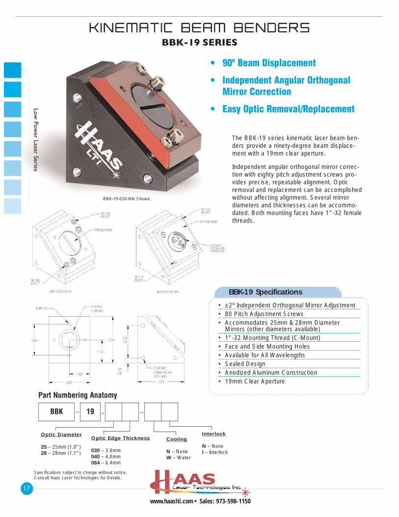
• 90º Beam Displacement
• Independent Angular Orthogonal Mirror Correction
• Easy Optic Removal/Replacement
The BBK-19 series kinematic laser beam ben-ders provide a ninety-degree beam displace-ment with a 19mm clear aperture.
Independent angular orthogonal mirror correc-tion with eighty pitch adjustment screws pro-vides precise, repeatable alignment. Opticremoval and replacement can be accomplishedwithout affecting alignment. Several mirrordiameters and thicknesses can be accommo-dated. Both mounting faces have 1”-32 femalethreads.
Optic Diameter
25 – 25mm (1.0”)28 – 28mm (1.1”)
Optic Edge Thickness
030 – 3.0mm040 – 4.0mm064 – 6.4mm
Cooling
N – NoneW – Water
BBK 19
Interlock
N – NoneI – Interlock
Part Numbering Anatomy
BBK-19 Specifications
• ±2º Independent Orthogonal Mirror Adjustment• 80 Pitch Adjustment Screws• Accommodates 25mm & 28mm Diameter
Mirrors (other diameters available)• 1”-32 Mounting Thread (C-Mount)• Face and Side Mounting Holes• Available for All Wavelengths• Sealed Design• Anodized Aluminum Construction• 19mm Clear Aperture
BBK-19-030-NN Shown.
KK IINNEEMMAATT IICC BBEEAAMM BBEENNDDEERRSSBBK-19 SERIES
17
www.haaslti.com • Sales: 973-598-1150
Specifications subject to change without notice.Consult Haas Laser Technologies for Details.
Low Pow
er Laser Series
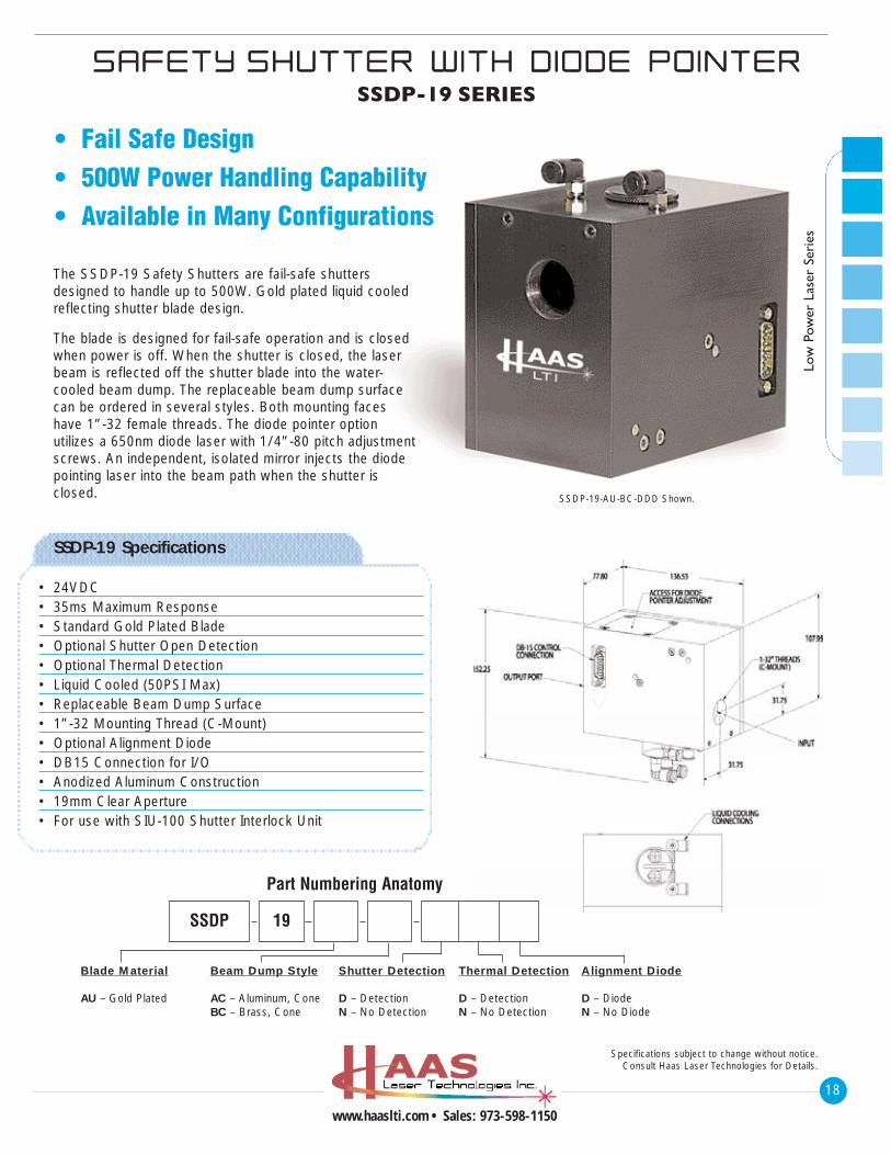
• Fail Safe Design• 500W Power Handling Capability• Available in Many Configurations
SSDP-19-AU-BC-DDD Shown.
The SSDP-19 Safety Shutters are fail-safe shuttersdesigned to handle up to 500W. Gold plated liquid cooledreflecting shutter blade design.
The blade is designed for fail-safe operation and is closedwhen power is off. When the shutter is closed, the laserbeam is reflected off the shutter blade into the water-cooled beam dump. The replaceable beam dump surfacecan be ordered in several styles. Both mounting faceshave 1”-32 female threads. The diode pointer option utilizes a 650nm diode laser with 1/4”-80 pitch adjustmentscrews. An independent, isolated mirror injects the diodepointing laser into the beam path when the shutter isclosed.
SSDP-19 Specifications
• 24VDC• 35ms Maximum Response• Standard Gold Plated Blade• Optional Shutter Open Detection• Optional Thermal Detection• Liquid Cooled (50PSI Max)• Replaceable Beam Dump Surface• 1”-32 Mounting Thread (C-Mount)• Optional Alignment Diode• DB15 Connection for I/O• Anodized Aluminum Construction• 19mm Clear Aperture• For use with SIU-100 Shutter Interlock Unit
Blade Material
AU – Gold Plated
Beam Dump Style
AC – Aluminum, ConeBC – Brass, Cone
Shutter Detection
D – DetectionN – No Detection
Thermal Detection
D – DetectionN – No Detection
Alignment Diode
D – DiodeN – No Diode
SSDP 19
Part Numbering Anatomy
18
www.haaslti.com • Sales: 973-598-1150
Low
Pow
er L
aser
Ser
ies
SSAAFFEETTYY SSHHUUTTTTEERR WWIITTHH DD IIOODDEE PPOO IINNTTEERRSSDP-19 SERIES
Specifications subject to change without notice.Consult Haas Laser Technologies for Details.
SSHHUUTTTTEERR IINNTTEERRLLOOCCKK UUNN IITTSIU-100 SERIES
19
www.haaslti.com • Sales: 973-598-1150
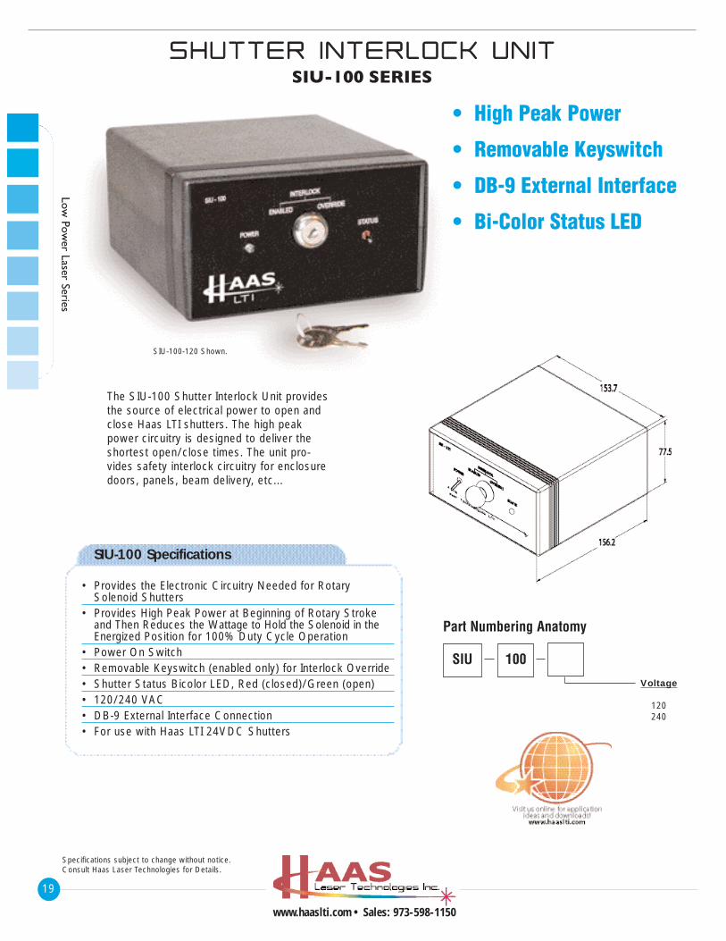
• High Peak Power
• Removable Keyswitch
• DB-9 External Interface
• Bi-Color Status LED
The SIU-100 Shutter Interlock Unit providesthe source of electrical power to open andclose Haas LTI shutters. The high peakpower circuitry is designed to deliver theshortest open/close times. The unit pro-vides safety interlock circuitry for enclosuredoors, panels, beam delivery, etc...
Specifications subject to change without notice.Consult Haas Laser Technologies for Details.
Low Pow
er Laser Series
SIU-100 Specifications
• Provides the Electronic Circuitry Needed for Rotary Solenoid Shutters
• Provides High Peak Power at Beginning of Rotary Stroke and Then Reduces the Wattage to Hold the Solenoid in the Energized Position for 100% Duty Cycle Operation
• Power On Switch• Removable Keyswitch (enabled only) for Interlock Override• Shutter Status Bicolor LED, Red (closed)/Green (open)• 120/240 VAC• DB-9 External Interface Connection• For use with Haas LTI 24VDC Shutters
Voltage
120240
SIU
Part Numbering Anatomy
100
SIU-100-120 Shown.
20
www.haaslti.com • Sales: 973-598-1150
LLAASSEERR BBEEAAMM DDUUMMPPBD-19 SERIES
Specifications subject to change without notice.Consult Haas Laser Technologies for Details.
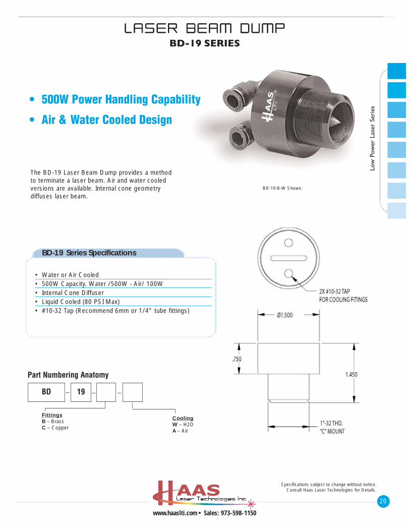
• 500W Power Handling Capability
• Air & Water Cooled Design
The BD-19 Laser Beam Dump provides a method to terminate a laser beam. Air and water cooled versions are available. Internal cone geometry diffuses laser beam.
BD-19 Series Specifications
• Water or Air Cooled• 500W Capacity. Water /500W - Air/ 100W• Internal Cone Diffuser• Liquid Cooled (80 PSI Max)• #10-32 Tap (Recommend 6mm or 1/4” tube fittings)
Low
Pow
er L
aser
Ser
ies
FittingsB – BrassC – Copper
BD 19
CoolingW – H2OA – Air
Part Numbering Anatomy
BD-19-B-W Shown.
BBEEAAMM SSHHUUTTTTEERR//DD IIOODDEE PPOO IINNTTEERRBSDP-19 SERIES
21
www.haaslti.com • Sales: 973-598-1150
Low Pow
er Laser Series
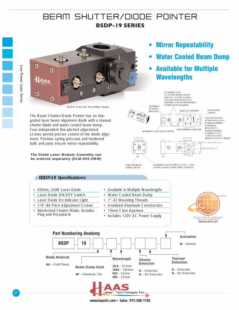
• Mirror Repeatability
• Water Cooled Beam Dump
• Available for Multiple Wavelengths
The Beam Shutter/Diode Pointer has an inte-grated laser beam alignment diode with a manualshutter blade and water cooled beam dump.Four independent fine-pitched adjustmentscrews permit precise control of the diode align-ment. Positive spring pressure and hardenedballs and pads ensure mirror repeatability.
The Diode Laser Module Assembly canbe ordered separately (DLM-650-2MW)
BSDP-19 Specifications
• 650nm, 2mW Laser Diode• Laser Diode ON/OFF Switch• Laser Diode On Indicator LIght• 1/4”-80 Pitch Adjustment Screws• Interlocked Shutter Blade, Includes
Plug and Receptacle
• Available in Multiple Wavelengths• Water Cooled Beam Dump• 1”-32 Mounting Threads• Anodized Aluminum Construction• 19mm Clear Aperture• Includes 120V AC Power Supply
Blade Material
AU – Gold PlatedBeam Dump Style
AF – Aluminum, Flat
Wavelength
10.6 – 10.6nm1064 – 1064nm532 – 532nm355 – 355nm
BSDP 19
ShutterDetection
D – DetectionN – No Detection
ThermalDetection
D – DetectionN – No Detection
Activation
M – Manual
Part Numbering Anatomy
BSDP-19-AU-AF-10.6-NNM Shown.
22
www.haaslti.com • Sales: 973-598-1150
Low
Pow
er L
aser
Ser
ies
BBEEAAMM CCOOMMBB IINNEERR//DD IIOODDEE PPOO IINNTTEERRBCDP-19 SERIES
Specifications subject to change without notice.Consult Haas Laser Technologies for Details.
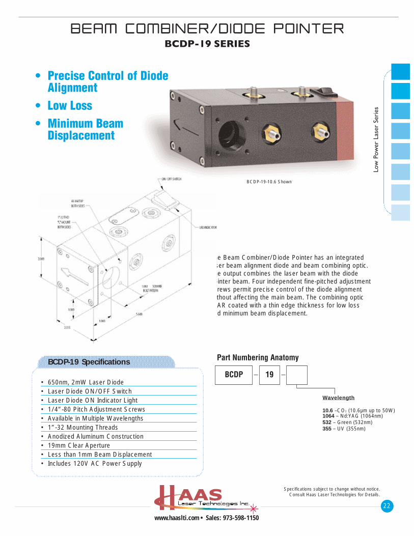
The Beam Combiner/Diode Pointer has an integratedlaser beam alignment diode and beam combining optic.The output combines the laser beam with the diode pointer beam. Four independent fine-pitched adjustmentscrews permit precise control of the diode alignmentwithout affecting the main beam. The combining optic is AR coated with a thin edge thickness for low loss and minimum beam displacement.
BCDP-19 Specifications
• 650nm, 2mW Laser Diode• Laser Diode ON/OFF Switch• Laser Diode ON Indicator Light• 1/4”-80 Pitch Adjustment Screws• Available in Multiple Wavelengths• 1”-32 Mounting Threads• Anodized Aluminum Construction• 19mm Clear Aperture• Less than 1mm Beam Displacement• Includes 120V AC Power Supply
Wavelength
10.6 –CO2 (10.6µm up to 50W)1064 – Nd:YAG (1064nm)532 – Green (532nm)355 – UV (355nm)
BCDP 19
Part Numbering Anatomy
• Precise Control of Diode Alignment
• Low Loss• Minimum Beam
Displacement
BCDP-19-10.6 Shown
BBEEAAMM SSWWIITTCCHH IINNGG UUNN IITTBSU-19 SERIES
23
www.haaslti.com • Sales: 973-598-1150
Specifications subject to change without notice.Consult Haas Laser Technologies for Details.
Low Pow
er Laser Series
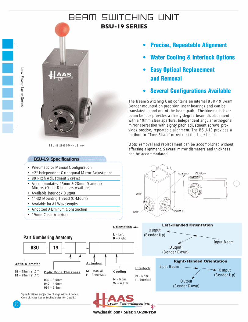
• Precise, Repeatable Alignment
• Water Cooling & Interlock Options
• Easy Optical Replacement and Removal
• Several Configurations Available
The Beam Switching Unit contains an internal BBK-19 BeamBender mounted on precision linear bearings and can betranslated in and out of the beam path. The kinematic laserbeam bender provides a ninety-degree beam displacementwith a 19mm clear aperture. Independent angular orthogonalmirror correction with eighty pitch adjustment screws pro-vides precise, repeatable alignment. The BSU-19 provides amethod to “Time-Share’ or redirect the laser beam.
Optic removal and replacement can be accomplished withoutaffecting alignment. Several mirror diameters and thicknesscan be accommodated.
BSU-19-28030-MNNL Shown
Left-Handed OrientationOutput
(Bender Up)
Output(Bender Down)
Input Beam
Right-Handed Orientation
Output(Bender Up)
Output(Bender Down)
Input Beam
BSU-19 Specifications
• Pneumatic or Manual Configuration• ±2º Independent Orthogonal Mirror Adjustment• 80 Pitch Adjustment Screws• Accommodates 25mm & 28mm Diameter
Mirrors (Other Diameters Available)• Available Interlock Output• 1”-32 Mounting Thread (C-Mount)• Available for All Wavelengths• Anodized Aluminum Construction• 19mm Clear Aperture
Optic Diameter
25 – 25mm (1.0”)28 – 28mm (1.1”)
Optic Edge Thickness
030 – 3.0mm040 – 4.0mm064 – 6.4mm
Cooling
N – NoneW – Water
Actuation
M – ManualP – Pneumatic
BSU 19
Interlock
N – NoneI – Interlock
Orientation
L – LeftR – RightPart Numbering Anatomy
24
www.haaslti.com • Sales: 973-598-1150
Low
Pow
er L
aser
Ser
ies
KK IINNEEMMAATT IICC BBEEAAMM SSPPLL IITTTTEERRBSK-19 SERIES
Specifications subject to change without notice.Consult Haas Laser Technologies for Details.
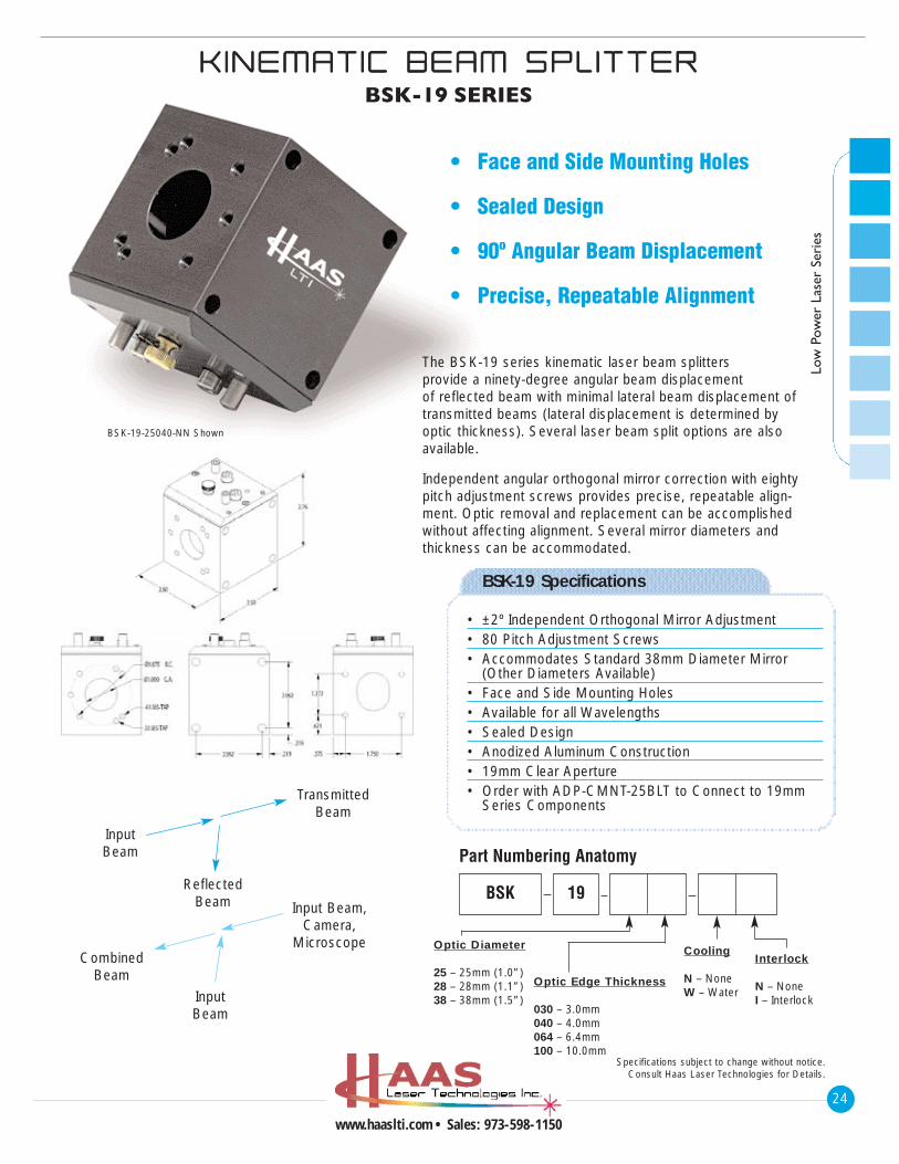
• Face and Side Mounting Holes
• Sealed Design
• 90º Angular Beam Displacement
• Precise, Repeatable Alignment
The BSK-19 series kinematic laser beam splitters provide a ninety-degree angular beam displacement of reflected beam with minimal lateral beam displacement oftransmitted beams (lateral displacement is determined byoptic thickness). Several laser beam split options are alsoavailable.
Independent angular orthogonal mirror correction with eightypitch adjustment screws provides precise, repeatable align-ment. Optic removal and replacement can be accomplishedwithout affecting alignment. Several mirror diameters andthickness can be accommodated.
BSK-19-25040-NN Shown
InputBeam
ReflectedBeam
TransmittedBeam
CombinedBeam
InputBeam
Input Beam,Camera,
Microscope
BSK-19 Specifications
• ±2º Independent Orthogonal Mirror Adjustment• 80 Pitch Adjustment Screws• Accommodates Standard 38mm Diameter Mirror
(Other Diameters Available)• Face and Side Mounting Holes• Available for all Wavelengths• Sealed Design• Anodized Aluminum Construction• 19mm Clear Aperture• Order with ADP-CMNT-25BLT to Connect to 19mm
Series Components
Optic Diameter
25 – 25mm (1.0”)28 – 28mm (1.1”)38 – 38mm (1.5”)
Optic Edge Thickness
030 – 3.0mm040 – 4.0mm064 – 6.4mm100 – 10.0mm
Cooling
N – NoneW – Water
BSK 19
Interlock
N – NoneI – Interlock
Part Numbering Anatomy
IINNDDUUSSTTRR IIAALL AARRTT IICCUULLAATTEEDD AARRMMARM-19 SERIES
25
www.haaslti.com • Sales: 973-598-1150
Specifications subject to change without notice.Consult Haas Laser Technologies for Details.
Low Pow
er Laser Series
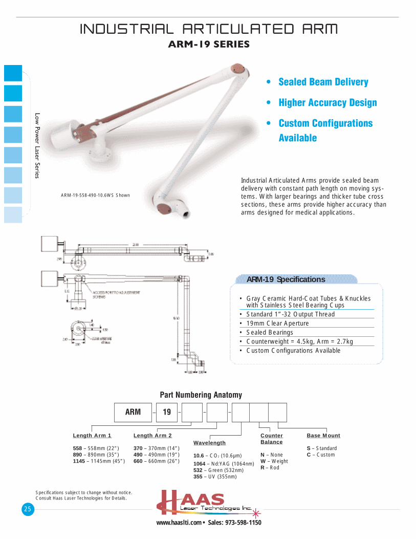
• Sealed Beam Delivery
• Higher Accuracy Design
• Custom Configurations Available
Industrial Articulated Arms provide sealed beamdelivery with constant path length on moving sys-tems. With larger bearings and thicker tube crosssections, these arms provide higher accuracy thanarms designed for medical applications.
ARM-19 Specifications
• Gray Ceramic Hard-Coat Tubes & Knuckles with Stainless Steel Bearing Cups
• Standard 1”-32 Output Thread• 19mm Clear Aperture• Sealed Bearings• Counterweight = 4.5kg, Arm = 2.7kg• Custom Configurations Available
Length Arm 1
558 – 558mm (22”)890 – 890mm (35”)1145 – 1145mm (45”)
Length Arm 2
370 – 370mm (14”)490 – 490mm (19”)660 – 660mm (26”)
Wavelength
10.6 – CO2 (10.6µm)
1064 – Nd:YAG (1064nm)532 – Green (532nm)355 – UV (355nm)
CounterBalance
N – NoneW – WeightR – Rod
Base Mount
S – StandardC – Custom
ARM 19
Part Numbering Anatomy
ARM-19-558-490-10.6WS Shown
26
www.haaslti.com • Sales: 973-598-1150
Low
Pow
er L
aser
Ser
ies
““QQUU IICCKK--MMOOUUNNTT”” BBEEAAMM DDEELL IIVVEERRYY
TTUUBBEESS && CCOOUUPPLLEERRSSBTQ-19 SERIES
Specifications subject to change without notice.Consult Haas Laser Technologies for Details.
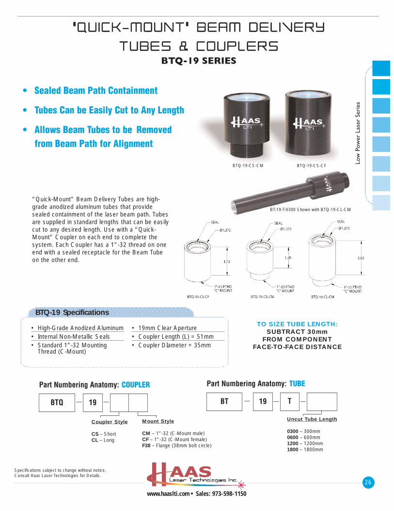
“Quick-Mount” Beam Delivery Tubes are high-grade anodized aluminum tubes that providesealed containment of the laser beam path. Tubesare supplied in standard lengths that can be easilycut to any desired length. Use with a “Quick-Mount” Coupler on each end to complete thesystem. Each Coupler has a 1”-32 thread on oneend with a sealed receptacle for the Beam Tubeon the other end.
TO SIZE TUBE LENGTH:SUBTRACT 30mm
FROM COMPONENT FACE-TO-FACE DISTANCE
BTQ-19 Specifications
• High-Grade Anodized Aluminum• Internal Non-Metallic Seals• Standard 1”-32 Mounting
Thread (C-Mount)
• 19mm Clear Aperture• Coupler Length (L) = 51mm• Coupler DIameter = 35mm
Uncut Tube Length
0300 – 300mm0600 – 600mm1200 – 1200mm1800 – 1800mm
BT
Part Numbering Anatomy: TUBE
19 T
Coupler Style
CS – ShortCL – Long
Mount Style
CM – 1”-32 (C-Mount male)CF – 1”-32 (C-Mount female)F38 – Flange (38mm bolt circle)
BTQ
Part Numbering Anatomy: COUPLER
19
BTQ-19-CS-CM BTQ-19-CS-CF
BT-19-T-0300 Shown with BTQ-19-CL-CM
• Sealed Beam Path Containment
• Tubes Can be Easily Cut to Any Length
• Allows Beam Tubes to be Removed from Beam Path for Alignment
BBEEAAMM TTUUBBEESS && LLOOCCKK IINNGG RR IINNGGBTA-19 SERIES
27
www.haaslti.com • Sales: 973-598-1150
Specifications subject to change without notice.Consult Haas Laser Technologies for Details.
Low Pow
er Laser Series
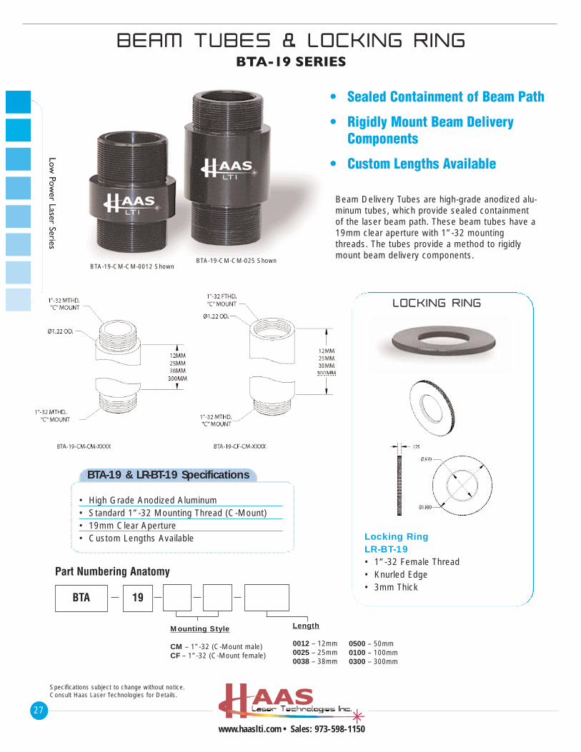
• Sealed Containment of Beam Path
• Rigidly Mount Beam Delivery Components
• Custom Lengths Available
Beam Delivery Tubes are high-grade anodized alu-minum tubes, which provide sealed containmentof the laser beam path. These beam tubes have a19mm clear aperture with 1”-32 mountingthreads. The tubes provide a method to rigidlymount beam delivery components.
Locking RingLR-BT-19• 1”-32 Female Thread• Knurled Edge• 3mm Thick
BTA-19 & LR-BT-19 Specifications
• High Grade Anodized Aluminum• Standard 1”-32 Mounting Thread (C-Mount)• 19mm Clear Aperture• Custom Lengths Available
Mounting Style
CM – 1”-32 (C-Mount male)CF – 1”-32 (C-Mount female)
Length
0012 – 12mm0025 – 25mm0038 – 38mm
0500 – 50mm0100 – 100mm0300 – 300mm
BTA
Part Numbering Anatomy
19
BTA-19-CM-CM-0012 ShownBTA-19-CM-CM-025 Shown
LLOOCCKK IINNGG RR IINNGG
28
www.haaslti.com • Sales: 973-598-1150
Low
Pow
er L
aser
Ser
ies
TTEELLEESSCCOOPP IICC BBEEAAMM TTUUBBEESSBTT-19 SERIES
Specifications subject to change without notice.Consult Haas Laser Technologies for Details.
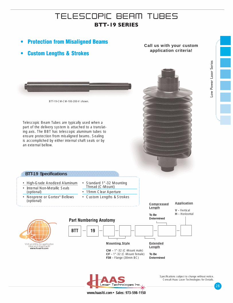
• Protection from Misaligned Beams
• Custom Lengths & StrokesCall us with your custom
application criteria!
Telescopic Beam Tubes are typically used when apart of the delivery system is attached to a translat-ing axis. The BBT has telescopic aluminum tubes toensure protection from misaligned beams. Sealingis accomplished by either internal shaft seals or byan external bellow.
BTT-19-CM-CM-100-200-V shown.
BTT-19 Specifications
• High-Grade Anodized Aluminum• Internal Non-Metallic Seals
(optional)• Neoprene or Gortex® Bellows
(optional)
• Standard 1”-32 Mounting Thread (C-Mount)
• 19mm Clear Aperture• Custom Lengths & Strokes
Mounting Style
CM – 1”-32 (C-Mount male)CF – 1”-32 (C-Mount female)F38 – Flange (38mm BC)
ExtendedLength
To BeDetermined
CompressedLength
To BeDetermined
Application
V – VerticalH – Horizontal
BTT
Part Numbering Anatomy
19
TTEELLEESSCCOOPP IICC BBEELLLLOOWW BBEEAAMM TTUUBBEESSBTB-19 SERIES
29
www.haaslti.com • Sales: 973-598-1150
Specifications subject to change without notice.Consult Haas Laser Technologies for Details.
Low Pow
er Laser Series
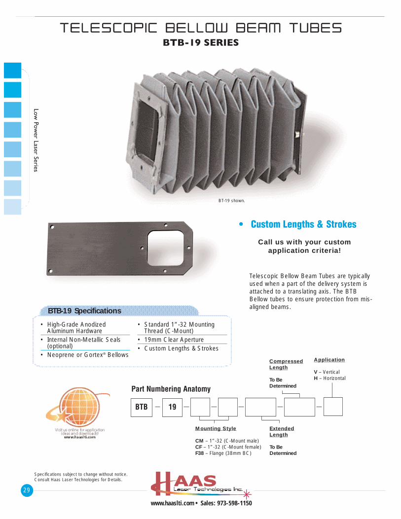
• Custom Lengths & Strokes
Call us with your customapplication criteria!
Telescopic Bellow Beam Tubes are typicallyused when a part of the delivery system isattached to a translating axis. The BTBBellow tubes to ensure protection from mis-aligned beams.
BT-19 shown.
BTB-19 Specifications
• High-Grade Anodized Aluminum Hardware
• Internal Non-Metallic Seals (optional)
• Neoprene or Gortex® Bellows
• Standard 1”-32 Mounting Thread (C-Mount)
• 19mm Clear Aperture• Custom Lengths & Strokes
Mounting Style
CM – 1”-32 (C-Mount male)CF – 1”-32 (C-Mount female)F38 – Flange (38mm BC)
ExtendedLength
To BeDetermined
CompressedLength
To BeDetermined
Application
V – VerticalH – Horizontal
BTB
Part Numbering Anatomy
19
30
www.haaslti.com • Sales: 973-598-1150
1199mmmm SSEERR IIEESS AACCCCEESSSSOORR IIEESS
TTAARRGGEETTSS//OOPPTT IICC WWRREENNCCHHEESS
Specifications subject to change without notice.Consult Haas Laser Technologies for Details.
Low
Pow
er L
aser
Ser
ies
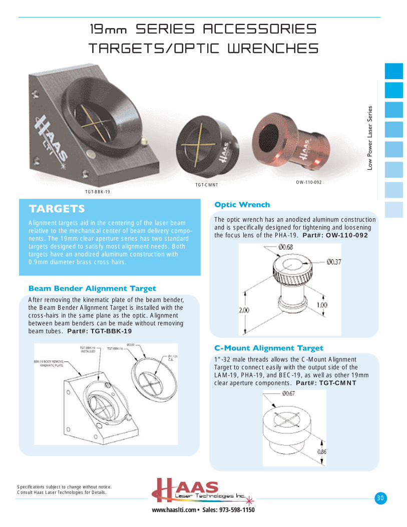
TARGETSAlignment targets aid in the centering of the laser beamrelative to the mechanical center of beam delivery compo-nents. The 19mm clear aperture series has two standardtargets designed to satisfy most alignment needs. Bothtargets have an anodized aluminum construction with0.9mm diameter brass cross hairs.
Beam Bender Alignment TargetAfter removing the kinematic plate of the beam bender,the Beam Bender Alignment Target is installed with thecross-hairs in the same plane as the optic. Alignmentbetween beam benders can be made without removingbeam tubes. Part#: TGT-BBK-19
C-Mount Alignment Target1”-32 male threads allows the C-Mount AlignmentTarget to connect easily with the output side of theLAM-19, PHA-19, and BEC-19, as well as other 19mmclear aperture components. Part#: TGT-CMNT
Optic Wrench
The optic wrench has an anodized aluminum constructionand is specifically designed for tightening and looseningthe focus lens of the PHA-19. Part#: OW-110-092
TGT-BBK-19
TGT-CMNT OW-110-092
CCOO22 LLAASSEERR NNEECCEESSSSIITT IIEESS
AALL IIGGNNMMEENNTT CCAARRDDSS // OOPPTT IICC CCLLEEAANN IINNGG
31
www.haaslti.com • Sales: 973-598-1150
Specifications subject to change without notice.Consult Haas Laser Technologies for Details.
Low Pow
er Laser Series
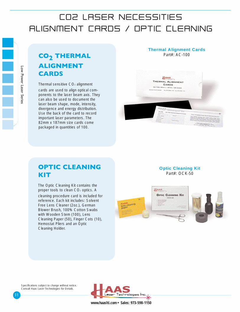
Thermal Alignment CardsPart#: AC-100
Optic Cleaning KitPart#: OCK-50
CO2 THERMAL
ALIGNMENTCARDSThermal sensitive CO2 alignment
cards are used to align optical com-ponents to the laser beam axis. Theycan also be used to document thelaser beam shape, mode, intensity,divergence and energy distribution.Use the back of the card to recordimportant laser parameters. The82mm x 187mm size cards comepackaged in quantities of 100.
OPTIC CLEANINGKITThe Optic Cleaning Kit contains theproper tools to clean CO2 optics. A
cleaning procedure card is included for reference. Each kit includes: SolventFree Lens Cleaner (2oz.), GermanBlower Brush, 100% Cotton Swabswith Wooden Stem (100), LensCleaning Paper (50), Finger Cots (10),Hemostat Pliers and an OpticCleaning Holder.
32
www.haaslti.com • Sales: 973-598-1150
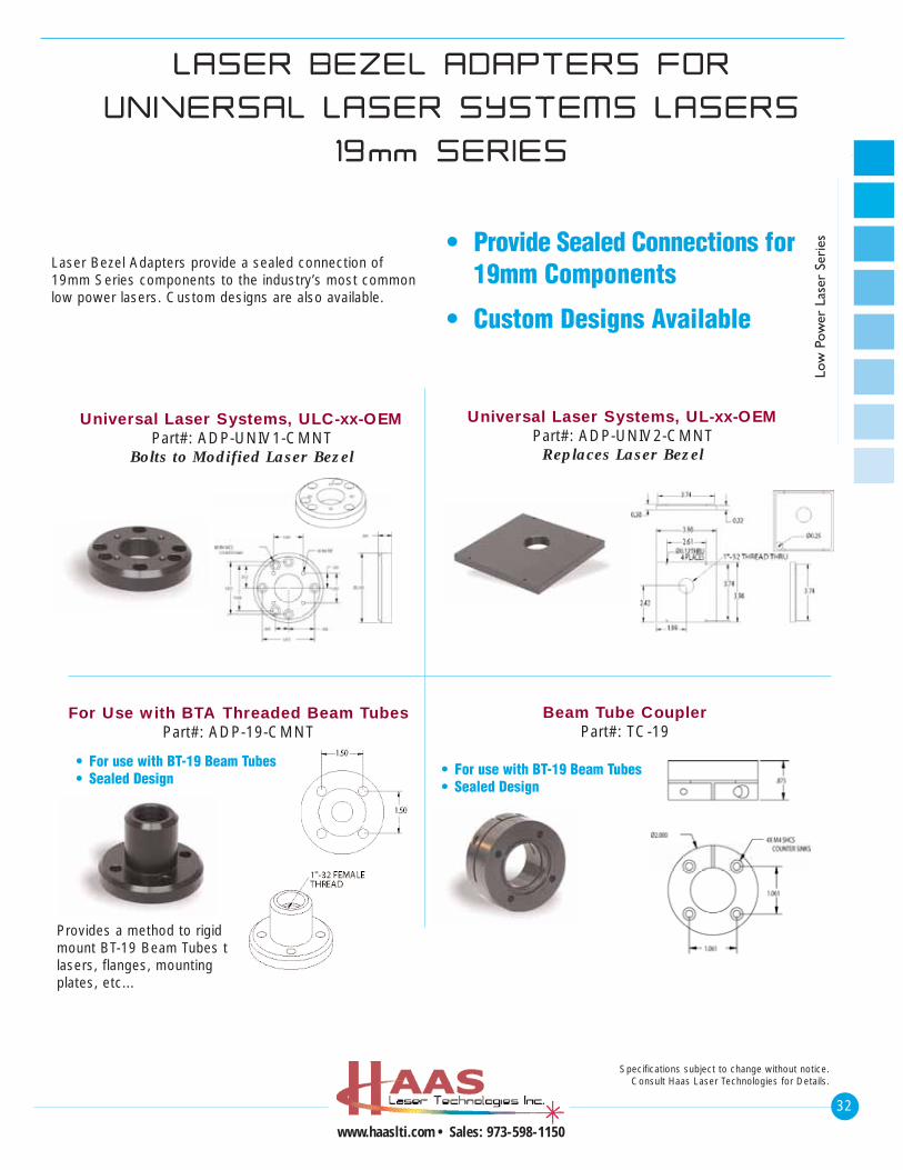
LLAASSEERR BBEEZZEELL AADDAAPPTTEERRSS FFOORR
UUNN IIVVEERRSSAALL LLAASSEERR SSYYSSTTEEMMSS LLAASSEERRSS
1199mmmm SSEERRIIEESS
Specifications subject to change without notice.Consult Haas Laser Technologies for Details.
Low
Pow
er L
aser
Ser
ies• Provide Sealed Connections for
19mm Components
• Custom Designs Available
Laser Bezel Adapters provide a sealed connection of19mm Series components to the industry’s most commonlow power lasers. Custom designs are also available.
Universal Laser Systems, ULC-xx-OEMPart#: ADP-UNIV1-CMNT
Bolts to Modified Laser Bezel
Universal Laser Systems, UL-xx-OEMPart#: ADP-UNIV2-CMNT
Replaces Laser Bezel
For Use with BTA Threaded Beam TubesPart#: ADP-19-CMNT
Beam Tube CouplerPart#: TC-19
Provides a method to rigidmount BT-19 Beam Tubes tolasers, flanges, mountingplates, etc...
• For use with BT-19 Beam Tubes• Sealed Design
• For use with BT-19 Beam Tubes• Sealed Design
33
www.haaslti.com • Sales: 973-598-1150
Specifications subject to change without notice.Consult Haas Laser Technologies for Details.
Low Pow
er Laser Series
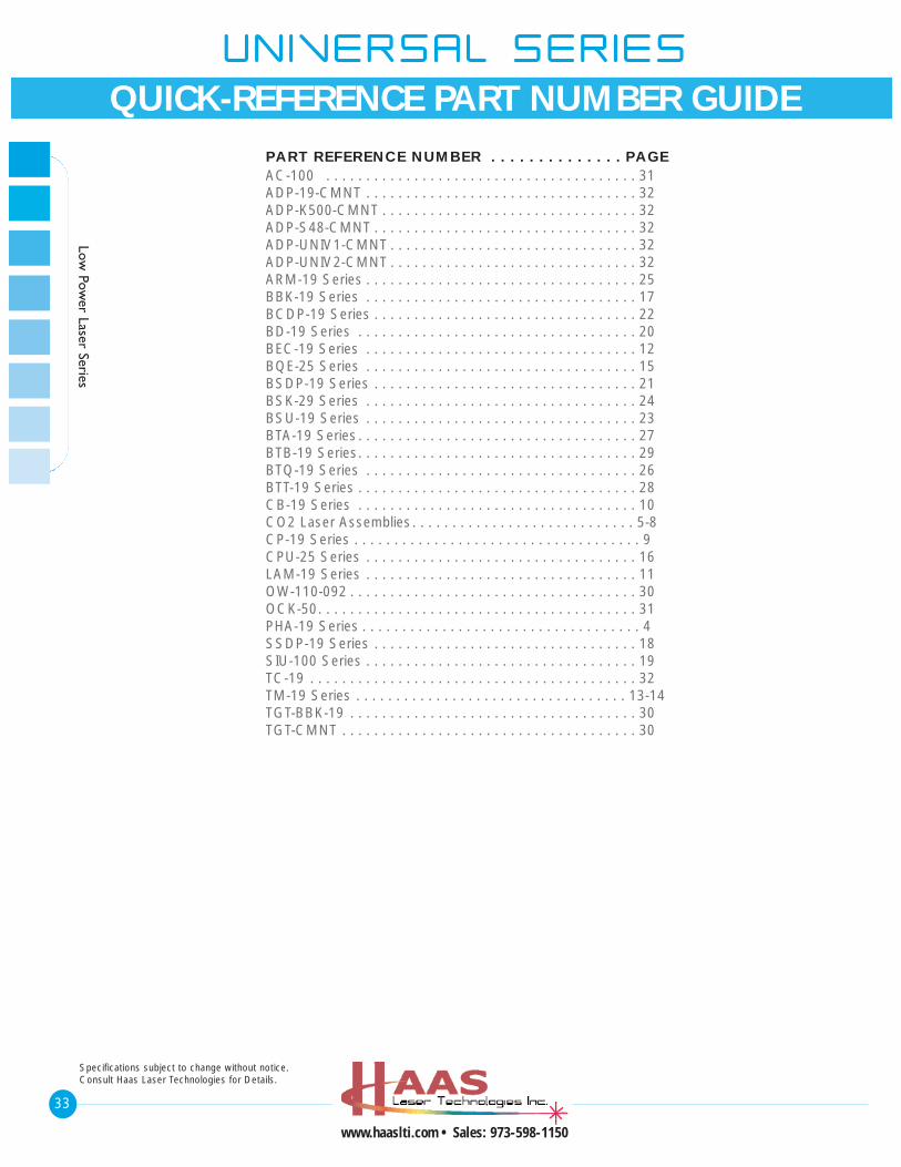
PART REFERENCE NUMBER . . . . . . . . . . . . . . PAGEAC-100 . . . . . . . . . . . . . . . . . . . . . . . . . . . . . . . . . . . . . . . 31ADP-19-CMNT . . . . . . . . . . . . . . . . . . . . . . . . . . . . . . . . . . 32ADP-K500-CMNT . . . . . . . . . . . . . . . . . . . . . . . . . . . . . . . . 32ADP-S48-CMNT . . . . . . . . . . . . . . . . . . . . . . . . . . . . . . . . . 32ADP-UNIV1-CMNT . . . . . . . . . . . . . . . . . . . . . . . . . . . . . . . 32ADP-UNIV2-CMNT . . . . . . . . . . . . . . . . . . . . . . . . . . . . . . . 32ARM-19 Series . . . . . . . . . . . . . . . . . . . . . . . . . . . . . . . . . . 25BBK-19 Series . . . . . . . . . . . . . . . . . . . . . . . . . . . . . . . . . . 17BCDP-19 Series . . . . . . . . . . . . . . . . . . . . . . . . . . . . . . . . . 22BD-19 Series . . . . . . . . . . . . . . . . . . . . . . . . . . . . . . . . . . . 20BEC-19 Series . . . . . . . . . . . . . . . . . . . . . . . . . . . . . . . . . . 12BQE-25 Series . . . . . . . . . . . . . . . . . . . . . . . . . . . . . . . . . . 15BSDP-19 Series . . . . . . . . . . . . . . . . . . . . . . . . . . . . . . . . . 21BSK-29 Series . . . . . . . . . . . . . . . . . . . . . . . . . . . . . . . . . . 24BSU-19 Series . . . . . . . . . . . . . . . . . . . . . . . . . . . . . . . . . . 23BTA-19 Series. . . . . . . . . . . . . . . . . . . . . . . . . . . . . . . . . . . 27BTB-19 Series. . . . . . . . . . . . . . . . . . . . . . . . . . . . . . . . . . . 29BTQ-19 Series . . . . . . . . . . . . . . . . . . . . . . . . . . . . . . . . . . 26BTT-19 Series . . . . . . . . . . . . . . . . . . . . . . . . . . . . . . . . . . . 28CB-19 Series . . . . . . . . . . . . . . . . . . . . . . . . . . . . . . . . . . . 10CO2 Laser Assemblies. . . . . . . . . . . . . . . . . . . . . . . . . . . . 5-8CP-19 Series . . . . . . . . . . . . . . . . . . . . . . . . . . . . . . . . . . . . 9CPU-25 Series . . . . . . . . . . . . . . . . . . . . . . . . . . . . . . . . . . 16LAM-19 Series . . . . . . . . . . . . . . . . . . . . . . . . . . . . . . . . . . 11OW-110-092 . . . . . . . . . . . . . . . . . . . . . . . . . . . . . . . . . . . . 30OCK-50. . . . . . . . . . . . . . . . . . . . . . . . . . . . . . . . . . . . . . . . 31PHA-19 Series . . . . . . . . . . . . . . . . . . . . . . . . . . . . . . . . . . . 4SSDP-19 Series . . . . . . . . . . . . . . . . . . . . . . . . . . . . . . . . . 18SIU-100 Series . . . . . . . . . . . . . . . . . . . . . . . . . . . . . . . . . . 19TC-19 . . . . . . . . . . . . . . . . . . . . . . . . . . . . . . . . . . . . . . . . . 32TM-19 Series . . . . . . . . . . . . . . . . . . . . . . . . . . . . . . . . . . 13-14TGT-BBK-19 . . . . . . . . . . . . . . . . . . . . . . . . . . . . . . . . . . . . 30TGT-CMNT . . . . . . . . . . . . . . . . . . . . . . . . . . . . . . . . . . . . . 30
UUNN IIVVEERRSSAALL SSEERR II EESS
QUICK-REFERENCE PART NUMBER GUIDE