Embed Size (px)
Citation preview
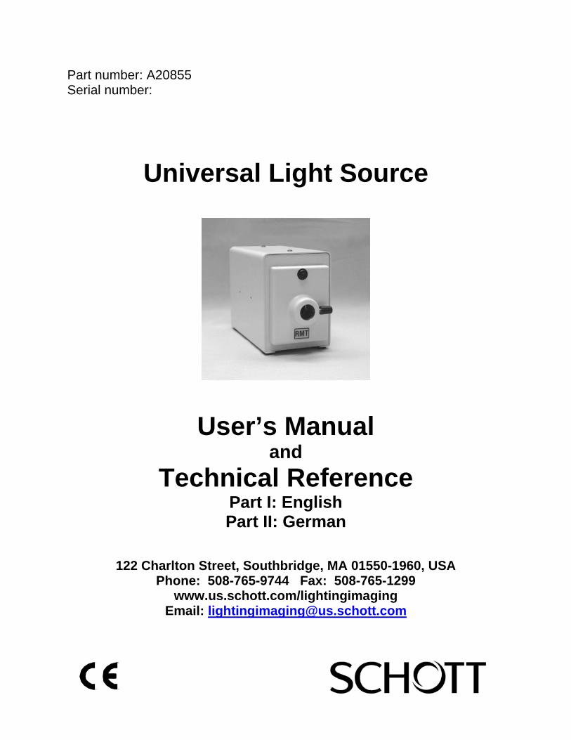
Part number: A20855 Serial number:
Universal Light Source
User’s Manual and
Technical Reference Part I: English Part II: German
122 Charlton Street, Southbridge, MA 01550-1960, USA Phone: 508-765-9744 Fax: 508-765-1299
www.us.schott.com/lightingimaging Email: [email protected]
Page 2
Warning 1. Never look directly at the lamp when on. 2. Lamp and surrounding surfaces may be hot! 3. Do not use this unit near water or in an area with excessive moisture. 4. Do not place flammable materials near the unit. 5. Refer to the Introduction Section for safety instructions.
Attention 1. Ne pas regarder directement la lampe quand elle fonctionne. 2. La lampe et son logement peuvent étre chaud. 3. Ne pas utiliser cette source près de l’eau ou d’une zone particulièrement humide. 4. Ne pas placer de matériau inflammable près de la source lumineuse. 5. Se référer à la Section d'Introduction pour les instructions de sûreté.
Warnhinweise 1. Niemals direkt in die Lampe blicken, wenn die Kaltlichtquelle eingeschaltet ist. 2. Die Lampe und angrenzende Oberflächen können heiss sein! 3. Betreiben Sie die Lichtquelle nicht in der Nähe von Wasser und bei extrem hoher
Luftfeuchtigkeit. 4. Halten Sie leicht entzündliches Material von der Lichtquelle fern. 5. Beachten Sie auch die Sicherheitshinweise im Abschnitt der technischen Hinweise.
Precauzioni 1. Mai guardare direttamente la lampadina quando é accessa. 2. La lampadina e la superficie circostante possono essere surriscaldate. 3. Non utilizzare il generatore in presenza di acqua o in aree eccessivamente sporche. 4. Non mettere materiali infiammabili vicino al generatore di luce. 5. Fare riferimento alla Sezione di Introduzione per le istruzioni di sicurezza.
Attender 1. Nunca mirada directamente en la lámpara cuando en. 2. La lámpara y las superficies cerca de la lámpara pueden estar muy calientes. 3. No use la unidad cerca del agua o en una zona muy humeda. 4. No ponga material inflamable cerca de la unidad. 5. Refiérase a la sección de introducción para instrucciones de seguridad.

Page 3
Part I: English Table of Contents
1. Introduction
1.1. Product Description...................................................................... 4 1.2. Safety Instructions....................................................................... 4
2. Operation
2.1. Voltage Input................................................................................ 4 2.2. Turning the Light Source On…………………………………….…. 5
3. Modulamp®
3.1. Modulamp® Assembly Removal…………………………………… 5 3.2. Lamp Replacement…………………………………………………. 6 3.3. Modulamp® Assembly Installation…………………………………. 7 3.4. Modulamp® Options……………………………………………….…8 3.5. Lamp Type Change……………………………………………….… 8
4. Appendix
4.1. Cleaning……………………………………………………………… 9 4.2. Troubleshooting……………………………………………………... 9 4.3. Product Specifications………………………………………………. 10 4.4. Replacement Parts……………………………………….…………. 11 4.5. Support/Service/RMA Policy…………………………….…………. 12

Page 4
1. Introduction:
1.1. Product Description: Congratulations on the purchase of your Universal Light Source. This light source provides cool, intense, white light for all types of fiber optic illumination components. The Universal Light Source is CSA listed to UL-1571 and CE compliant to low voltage and EMC directives. The Universal Light Source was designed and manufactured under the ISO 9000 guidelines. The Universal Light Source was designed to be an extension of the DCR® III Light Source. However, any power supply that doesn’t exceed 21 VDC at 8 amps will operate the Universal Light Source. The removable Modulamp® assembly contains the lamp holder, which supports three different lamp choices depending on intensity, lifetime and uniformity requirements, or any MR-16 lamp that does not exceeding the power requirements.
1.2. Safety Instructions:
1. Read, understand and follow all instructions in this manual. 2. Keep all safety and operating instructions for future reference. 3. Do not block ventilation openings on this unit. Do not impede airflow. 4. Use only standard glass type cleaners. Do not use solvents or petroleum
distillates. 5. Never spill liquid on the unit or push objects into ventilation openings. 6. Disconnect power cord when unit will be left unused for long periods
of time. 7. Allow the unit to cool before servicing. 8. Do not service the unit beyond what is described in this manual. Return the
light source to an authorized SCHOTT service center. For a Return Material Authorization see Section 4.5.
2. Operation:
2.1. Voltage Input:
1. The Universal Light Source was designed to accept a varying DC voltage between 0 and 21 Volts. This voltage is lamp-dependent; therefore you should not exceed the lamp manufacturers rated voltage and power consumption. Note: The Universal Light Source utilizes a DC fan that will vary with the voltage supplied to the unit.

Page 5
2.2. Turning the Light Source “on”:
1. Insure the power switch on the back panel is in the “off” position (A). 2. Plug an appropriate cable into the Amp CPC Connector (B). 3. To help minimize current loss the Amp CPC Connector pins have been split into two groups: pins 1 and 2 are the +VDC (C), and Pins 3 and 4 are the – VDC (D).
4. All information regarding the AMP CPC Connector can be found on their web site: http://www.amp.com. Search under part number: 206430. Cabling options are available. Please contact SCHOTT Sales Department.
5. Make sure that the captive thumbscrew on the Modulamp® assembly is firmly tightened.
6. Insert any fiber optic component with a compatible light source adapter into the Modulamp® receptacle.
7. Tighten the fiber optic positioning thumbscrew (see diagram). 8. Turn the light source power switch to the “on” position. 9. To turn the unit off, press the power switch to the “off” position.
3. Modulamp®:
3.1. Modulamp® Assembly Removal:
1. Turn the power switch to the “off” position. 2. Remove the fiber optic component. 3. Allow the lamp to cool. 4. Unscrew the Modulamp® assembly captive thumbscrew until the head springs forward. CAUTION: Lamp, lamp socket and surrounding surfaces may be hot!

Page 6
5. Pull the top of the Modulamp® assembly forward and lift the unit out of the recess.
6. Reach into the recess and depress the release tab on the connector. 7. Slide the connector apart and remove the Modulamp® assembly.
3.2. Lamp Replacement:
1. Turn the power switch to the “off” position. 2. Remove the fiber optic component. 3. Allow the lamp to cool. 4. Unscrew the Modulamp® assembly captive thumbscrew until the head springs forward (H). CAUTION: Lamp, lamp socket and surrounding surfaces may be hot!
5. Pull the top of the Modulamp® assembly forward and lift the unit out of the recess.
6. Push back on the lampholder release lever to raise the lamp (L). 7. Gently unplug the ceramic lamp socket (K). 8. Lift the release lever. Insert a new lamp into the lamp holder. Push the lamp
all the way down. Be careful not to touch the bulb or the inside of the reflector. Fingerprints may affect the light output.
9. Push the ceramic socket on to the two lamp pins until flush with the lamp base.
10. Return the Modulamp® assembly into the recess and tighten captive thumbscrew.
11. For complete Modulamp® assembly removal and installation, see Sections 3.1 and 3.3.

Page 7
3.3. Modulamp® Assembly Installation:
1. Make sure the power switch is in the “off” position. 2. Slide the connector into the mating receptacle until the release tab
clicks into place. 3. Place the Modulamp® assembly into the recess with the two-bottom “ears”
riding over the bottom edge of the recess first. 4. Slide the Modulamp® assembly into place. 5. Depress the captive thumbscrew and tighten firmly.

Page 8
3.4. Modulamp® Options:
The Modulamp® assembly allows you the convenience of changing the lamp, lamp type or intensity control (iris) by simply exchanging Modulamp® assemblies.
Modulamp Assembly Part Number Without Iris A08301, EKE Position
A08301.1, EJA Position A08301.2, DDL Position
With Iris
A08321, EKE Position A08321.1, EJA Position A08321.2, DDL Position
3.5. Lamp Type Change:
1. Each Modulamp® assembly can be adjusted to accommodate any of the three recommended lamps (EJA, EKE or DDL). Repositioning after changing the lamp type is very important. It will assure maximum intensity at the fiber optic input.
2. After removing the Modulamp® assembly from the housing, note the two sets of pre-drilled holes provided in the Modulamp® base.
3. The set of holes closest to the front of the Modulamp® assembly provide the correct positioning for the EJA and EKE lamps. The set of holes furthest from the front of the Modulamp® assembly are positioned for the DDL lamp.
4. To move the lamp holder, remove the two screws holding the lamp holder to the Modulamp® base, align the set of holes for the desired position, and screw the holder back into place.

Page 9
4. Appendix:
4.1. Cleaning:
The metal housing and the “Lexan” front and back decals have a durable finish that should retain their original luster for many years to come. Cleaning the exposed areas with a commercial glass cleaner will help to maintain the finish. Press the power switch on the front of the unit to the “off” position. Remove the power cord from the CPC connector on the back of the unit. Wipe the exposed areas of the housing and front and back plates with a soft cloth or paper towel moistened with any commercial glass cleaner. CAUTION: Do not use detergents, excess water, treated cloths, harsh cleaning agents or sprays. Use cleaning fluid sparingly. If fluid is spilled into the interior let the unit dry thoroughly before using. Periodically, dust should be removed from the unit using commercially available cans of compressed air. Pay special attention to the fan blades at the rear of the unit, the air vents in the front and bottom of the unit and the Modulamp® assembly.
4.2. Troubleshooting:
If you are unsuccessful at resolving the following conditions, contact SCHOTT. See Section 4.5 for a Return Materials Authorization (RMA). Do not attempt to repair the light source. Removing the cover will void the warranty. Do not attempt to troubleshoot the light source with any remote control device connected. If the light source operates after removal of the remote connection, check your remote set-up. 1. Neither fan nor lamp operates:
(Note that fan and lamp circuits are tied together.) • Make sure the power cord is inserted completely into the AMP
connector and also into the correct power source. • Make sure AMP CPC is plugged in completely. • Check the extension cord for damage. • Check power switch.
2. Universal Light Source turns on/off:
• Universal Light Source ambient too high. • Check vent holes for obstruction.

Page 10
4.3. Product Specifications:
1. Physical Dimensions: Overall Height: 4.62” (177 mm) Overall Width: 7.27” (185 mm) Overall Depth: 8.61” (219 mm) Fiber Receptacle: . 720” (18.3 mm) diameter
2. Environmental Conditions: Operating Temperature Range: 32 to 113° F, (0 to 45° C) Storage Temperature Range: -13 to 185° F, (-25 to 85° C) Relative Humidity Range: 0 to 95%, Non-condensing
3. Electrical Specifications: Input Voltage: 0 – 21 VDC @ 8 Amps CSA listed to UL (1571)
NOTE: Improvements may result in specification or feature changes without notice.

Page 11
4.4. Replacement Parts List: The following replacement parts are available from SCHOTT to maintain and support your Universal Light Source:
A08110, Lamp – EJA A08120, Lamp – EKE A08130, Lamp – DDL A29506, Lamp Socket , Assembly D08375.063, Scr, Assy, Thumb, Modulamp® D20855.14, Manual, Remote, Technical Reference.
Please Note: SCHOTT Light Sources are designed to be used exclusively with Ushio or GE lamps. Light Source performance will not be guaranteed with any other manufacturer's lamps.

Page 12
4.5. Support/Service/RMA Policy: Support: SCHOTT maintains a variety of support services to assist you: In USA: Telephone (1)315-255-2791, Fax (1)315-255-2695 In Europe: Telephone +49-6131-667796, Fax +49-6131-667850 Contact your local SCHOTT distributor from whom you made your purchase for an immediate response. Be sure to have your part number and serial number available, as well as a complete description of the problem or situation for the quickest, most accurate assistance. Service/RMA Policy: Any service required for any reason must be performed by SCHOTT or an authorized service representative. All service outside warranty will be performed upon the purchaser’s request according to normal service charges in effect at the time. To return any item, whether for warranty repair or chargeable servicing, an RMA number (Return Materials Authorization) must be obtained from SCHOTT. This number must be clearly visible on the shipping label. All shipping must be prepaid. SCHOTT guarantees all warranty repairs will be completed within two weeks of receipt. All units will ship prepaid using our shipping method of choice. Alternate shipping methods will be shipped freight collect.

Page 13
Part II: German
Inhaltsverzeichnis
1. Einleitung
1.1 Produktbeschreibung................................................................... 14 1.2 Sicherheitshinweise..................................................................... 14
2. Betrieb der Lichtquelle
2.1 Eingangsspannung...................................................................... 15 2.2 Einschalten der Lichtquelle ......................................................... 15
3. Modulamp® Lampeneinheit 3.1 Entfernen der Modulamp® Lampeneinheit.................................. 16
3.2 Installation der Modulamp® Lampeneinheit ................................ 16 3.3 Modulamp® Optionen.................................................................. 18 3.4 Wechseln des Lampentyps........................................................ 18
4. Appendix 4.1 Reinigung.................................................................................... 19 4.2 Problembehebung....................................................................... 19 4.3 Produktspezifikation.................................................................... 20 4.4 Ersatzteile................................................................................... 21 4.5 Support/Service.......................................................................... 22
Page 14
1. Einleitung
1.1 Produktbeschreibung: Wir gratulieren zum Erwerb der Universal Lichtquelle. Diese Lichtquelle liefert intensives, kaltes Weißlicht für alle Arten von faseroptischer Beleuchtung. Die Universal Lichtquelle ist CSA gelistet nach UL-1571 und entspricht den CE Richtlinien für Niederspannung und EMV. Die Universal Lichtquelle wurde konstruiert und hergestellt gemäß den Richtlinien der ISO 9000. Die Universal Lichtquelle wurde entwickelt als eine Erweiterung der DCR® III Lichtquelle. Unabhängig davon kann sie mit jeder Spannungsversorgung, die 21 Volt Gleichspannung bei 8 Apere nicht überschreitet, betrieben werden. Die entfernbare Modulamp® Lampeneinheit enthält den Lampenhalter, der verschiedene Lampentypen im MR-16 Format aufnimmt, welche die Leistungsdaten der Einheit nicht überschreiten.
1.2 Sicherheitshinweise 1. Bitte lesen und befolgen Sie diese Gebrauchsanweisung gewissenhaft. 2. Bewahren Sie alle Sicherheits- und Betriebshinweise auf, um später ggf.
etwas nachschlagen zu können. 3. Achten Sie darauf, dass die Belüftungsöffnungen des Geräts stets frei sind.
Der Luftstrom darf nicht behindert werden. 4. Verwenden Sie nur handelsübliche Glasreiniger. Lösungsmittel oder
Petroleumdestillate dürfen nicht eingesetzt werden. 5. Keine Flüssigkeiten auf dem Gerät verschütten oder Gegenstände in die
Belüftungsöffnungen stecken. 6. Ziehen Sie den Netzstecker, wenn das Gerät längere Zeit nicht verwendet
wird. 7. Das Gerät vor der Wartung zunächst auskühlen lassen. 8. Das Gerät darf nur soweit gewartet werden, wie in dieser Gebrauchs
anweisung beschrieben. Jede darüber hinausgehende Wartung oder Reparatur darf nur durch eine autorisierte SCHOTT Kundendienststelle durchgeführt werden. Hinweise in Bezug auf eine RMA (Return Material Authorization = Warenrücksende-Genehmigung) finden Sie in Abschnitt 4.5.

Page 15
2. Betrieb der Lichtquelle
2.1 Eingangsspannung:
Die Universal Lichtquelle wurde entwickelt für eine variable Eingangsspannung zwischen 0 und 21 volt, abhängig vom jeweiligen Lampentyp. Die vom Lampenhersteller angegebenen Werte für Lampenspannung sowie Leistung sollten nicht überschritten werden.
Bitte beachten Sie: Die Universal Lichtquelle verfügt über einen Lüfter, dessen Umdrehungszahl mit der angelegten Lampenspannung proportional ist.
2.2 Einschalten der Lichtquelle:
1. Stellen Sie sicher, dass sich der Ein/Aus-Schalter auf der Rückseite des Gerätes in “Aus”-Position befindet (A).
2. Verbinden Sie ein geeignetes Kabel mit dem AMP CPC Anschluss (B). 3. Um Leistungsverlusste zu vermindern, sind die Pins des AMP CPC Anschlusses in zwei Gruppen aufgeteilt worden: Pin 1 und 2 sind +VDC (C), Pin Pins 3 und 4 sind –VDC (D).
4. Weitere Informationen bezüglich der AMP CPC Anschlüsse können der Website: http://www.amp.com entnommen werden. Die Artikelnummer ist 206430. Kabelkonfektionierung ist als Option möglich. Bitte kontaktieren Sie den Vertrieb von SCHOTT Lighting and Imaging.
5. Stellen Sie sicher, dass die Arretierschraube der Modulamp� Lampeneinheit fest angezogen ist. 6. Verbinden sie ein faseroptisches Bauteil mit passendem Anschluss mit der Öffnung der Modulamp� Lampeneinheit. 7. Ziehen Sie die seitliche Feststellschraube (siehe Zeichnung) an. 8. Schalten Sie den An/Aus-Schalter in die “An” Position.

Page 16
9. Um die Lichtquelle auszuschalten, setzen Sie den Schalter in die “Aus”-Position.
3. Modulamp® Lampeneinheit
3.1 Entfernen der Modulamp® Lampeneinheit
1. Den Netzschalter auf die Position „OFF“ stellen. 2. Die Faseroptik-Komponente entfernen. 3. Lampe auskühlen lassen. ACHTUNG: Lampe, Lampenfassung und die umliegenden Oberflächen
können heiß sein! 4. Arretierschraube der Modulamp® Lampeneinehit lösen, bis der Knopf nach vorn
springt. Den oberen Teil der Modulamp® Lampeneinheit nach vorn ziehen und aus der Öffnung heben.
5. In die Öffnung greifen und die Arretierung am Lampensockelstecker lösen. 6. Die Modulamp® Lampeneinheit aus der Geräteöffnung herausnehmen.
3.2 Installation der Modulamp® Lampeneinheit
1. Darauf achten, dass der Netzschalter auf Position „OFF“ steht. 2. Den Lampensockelstecker mit dem Gegenstück verbinden, bis der
Spannhebel einklickt. 3. Die Modulamp® Lampeneinheit in die Öffnung stellen, wobei die beiden
„Ohren“ am Boden zunächst über den unteren Rand der Vertiefung ragen. 4. Die Modulamp® Lampeneinheit an ihren Platz schieben. 5. Die Arretierschraube andrücken und fest anziehen.

Page 17
anheben
nach vorne
Arretierschraube
Feststellschraube Aufnahme Faseroptik
Modulamp® Lampeneinheit

Page 18
3.3 Modulamp® Optionen:
Die Modulamp® Lampeneinheit ermöglicht Ihnen schnellen Wechsel der Lampe, des Lampentyps oder der Intenitätsregelung (Irisblende) durch Austausch der gesamten Einheit.
Modulamp® Baugruppe Artikelnummer Ohne Irisblende A08301, EKE Position
A08301.1, EJA Position A08301.2, DDL Position
Mit Irisblende
A08321, EKE Position A08321.1, EJA Position A08321.2, DDL Position
3.4 Wechsel des Lampentyps:
Jede Modulamp® Lampeneinheit kann auf einen der empfohlenen Lampentypen umgestellt werden (EJA, EKE oder DDL). Dabei ist es wichtig, die Position der Lampe in der Modulamp® Einheit zu justieren, damit die maximale Intensität in das faseroptische Bauteil eingekoppelt werden kann.
Nach Entfernen der Modulamp® Lampeneinheit aus dem Gehäuse zwei Paare Bohrungen am Boden der Modulamp® Basisplatte beachten. Die beiden Bohrungen nahe der Frontplatte der Einhit sind die korrekte Positionierung für EJA und EKE Lampen. Die beiden hinteren Bohrungen Positionieren die DDL Lampe.
Um den Lampenhalter zu versetzen, entfernen Sie die beiden Schrauben, die den Lampenhalter mit der Modulamp® Basisplatte verbinden und setzen den Halter in seine neue Position. Ziehen Sie die Schrauben wieder fest an.

Page 19
4. Appendix:
4.1 Reinigung
Das Stahlgehäuse und die Front- und Rückplatte aus dem Kunststoff Lexan sind mit einer strapazierfähigen Beschichtung ausgerüstet, die ihren ursprünglichen Glanz jahrelang bewahrt. Das Reinigen der offenen Bereiche mit einem handelsüblichen Glasreiniger schont die Oberflächen. Stellen Sie den Netzschalter an der Frontblende des Geräts auf die Position OFF. Entfernen Sie das Kabel aus dem CPC-Anschluss auf der Rückseite des Geräts. Wischen Sie die freien Stellen von Gehäuse und Vorder- und Rückplatte mit einem weichen Stoff- oder Papiertuch ab, das vorher mit einem handelsüblichen Glasreiniger befeuchtet wurde. ACHTUNG: Der Gebrauch von Spülmittel, zu viel Wasser, beschichteten Tüchern, scharfen Reinigungsmitteln oder Sprays ist zu vermeiden. Reinigungsflüssigkeit nur sparsam verwenden. Falls Flüssigkeit ins Geräteinnere gelangt, das Gerät vor Inbetriebnahme zunächst trocknen lassen. Das Gerät regelmäßig mit einem Staubsauger oder handelsüblichen Druckluftdosen von Staub befreien. Dabei besondere Vorsicht bei den Ventilatorblättern an der Rückseite des Geräts, den Luftöffnungen vorn und unten sowie der Modulamp Baugruppe.
4.2 Beheben von Störungen
Falls es Ihnen nicht gelingt, folgende Fehler zu beheben, wenden Sie sich bitte an SCHOTT. Siehe Abschnitt 8.5 in Bezug auf RMA (Return Materials Authorization = Warenrücksende-Genehmigung). Versuchen Sie nicht, die Lichtquelle selber zu reparieren. Durch Entfernen des Gehäusedeckels geht Ihr Garantieanspruch verloren. Lüfter in Betrieb, aber niedrige Lichtausbeute. • Korrekten Sitz von Lampe und Stecker prüfen. Siehe Abschnitt 7.3. • Lampe wechseln.
Weder Lüfter noch Lampe in Betrieb (bitte beachten Sie, dass Lüfter und Lampenansteuerung miteinander verbunden sind.) • Prüfen, ob das Netzkabel vollständig im AMP-Anschluss und in der richtigen Spannungsquelle sitzt. • Stellen Sie sicher, dass der AMP CPC-Anschluss fest verbunden ist. • Überprüfen Sie das Netzkabel auf Beschädigung. • Überprüfen Sie den An/Aus-Schalter

Page 20
Universal Lichtquelle geht an/aus • Umgebungstemperaturen zu hoch. • Lüfterschlitze sind nicht frei.
4.3 Produkt Spezifikation:
Abmessungen: Höhe: 4.62” (177 mm) Breite: 7.27” (185 mm) Tiefe: 8.61” (219 mm)
Aufnahme Faseroptik .720” (18.3 mm) Durchmesser
Umgebungsbedingungen: Betriebstemperatur: 32 bis 113° F, (0 - 45° C) Lagertemperatur: -13 bis 185° F, (-25 - 85° C)
Relative Luftfeuchtigkeit: 0 bis 95%, Nicht-konsensierend
Elektrische Spezifikation: Eingangsspannung: 0 – 21 VDC @ 8 Ampere
CSA gelisted gemäß UL (1571) Spezifikation
Bitte beachten: Technische Änderungen vorbehalten

Page 21
4.4 Ersatzteile
Die folgenden Ersatzteile sind von SCHOTT erhältlich zur Wartung und Service der Universal Lichtquelle:
A08110 Halogenlampe – Typ EJA A08120 Halogenlampe – Typ EKE A08130 Halogenlampe – Typ DDL A29506 Lampensockel , Baugruppe D08375.063 Arretierschraube Modulamp® D20855.14 Gebrauchsanleitung

Page 22
4.5 Technische Unterstützung/Kundendienst/RMA-Richtlinie
Technische Unterstützung: SCHOTT bietet Ihnen eine Reihe von Möglichkeiten zur technischen Unterstützung. Wenn Sie direkte Hilfe von unseren Vertriebspartnern oder Vertriebstechnikern brauchen, wenden Sie sich bitte direkt an SCHOTT: In den USA: Telefon (1)315-255-2791, Fax (1)315-255-2695 In Europa: Telefon +49-6131-667796, Fax +49-6131-667850 Oder wenden Sie sich direkt an den SCHOTT Händler, bei dem Sie das Gerät gekauft haben. Damit wir Ihnen so schnell und so gut wie möglich weiterhelfen können, bitten wir Sie, Bestell- und Seriennummer sowie eine vollständige Beschreibung des Problems griffbereit zu haben.
Kundendienst/RMA-Richtlinie Der Kundendienst in jeder Form kann nur von SCHOTT oder einem autorisierten Kundendienstrepräsentanten durchgeführt werden. Alle Kundendienstleistungen, die nicht unter die Garantie fallen, werden auf Anforderung des Kunden unter Einhaltung der jeweils geltenden Gebühren durchgeführt. Für die Rückgabe eines Produkts im Rahmen oder außerhalb der Garantie ist eine RMA-Nummer (Return Materials Authorization = Warenrücksende-Genehmigung) bei SCHOTT einzuholen. Diese Nummer muss deutlich erkennbar auf dem Versandetikett angegeben sein. Die Versandkosten müssen bezahlt sein.
SCHOTT gewährleistet, dass alle Garantiereparaturen innerhalb von zwei Wochen nach Eingang erledigt werden. Die Rücksendung der Geräte erfolgt bei vorausbezahlten Transportkosten mit der von uns gewählten Versandart. Im Fall von alternativen Versandmethoden hat der Empfänger die Frachtkosten per Nachnahme zu übernehmen.

Page 23
Lighting and Imaging SCHOTT North America, Inc. 122 Charlton Street Southbridge, MA 01550-1960 USA
PHONE: +1 (508) 765-9744 FAX: +1 (508) 765-1299 E-MAIL: [email protected] WEBSITE: www.us.schott.com/lightingimaging
Rev. B -January 2010