Embed Size (px)
Citation preview
Janitza electronics GmbHVor dem Polstück 1D-35633 LahnauSupport Tel. (0 64 41) 9642-22Fax (0 64 41) 9642-30e-mail: [email protected]: http://www.janitza.de
ww
w.ja
nit
za.d
e
Dok
Nr.
1.03
2.02
7.2m
Fir
mw
are
Rel
.: 0.
99
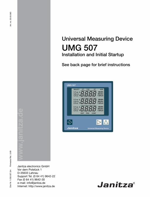
Universal Measuring Device
UMG 507Installation and Initial Startup
See back page for brief instructions
Art
. no.
33.
03.0
63
2
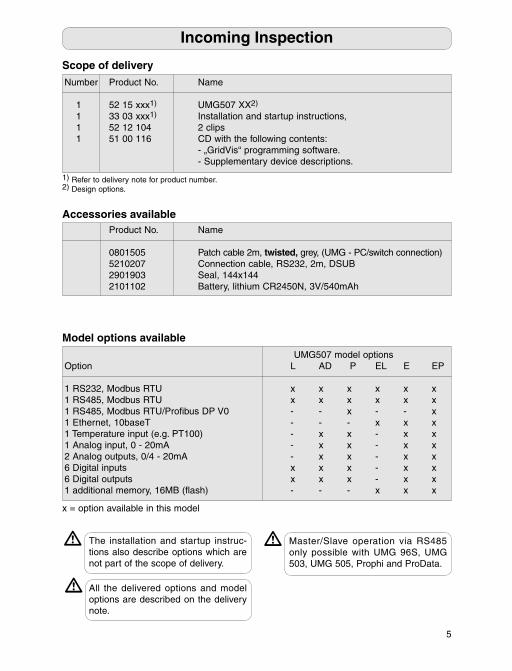
Incoming Inspection 4Meaning of the symbols used 4Incoming inspection 4Scope of delivery 5Accessories available 5Model options available 5
Product Description 6Practical guidance on use 6Intended use 6
Installation 8Installation location 8Protective conductor 8Supply voltage 8Connection options 9Voltage measurement 10Current measurement 11Interfaces 12RS485 12RS485 Profi bus 13Digital inputs and outputs 14Analog inputs and outputs 16
Initial Startup 18Install device 18Connect device 18Apply supply voltage 18Apply measurement voltage 18Apply measurement current 18
Operation 19Operation and display 19Measured value displays 20SELECT mode 20PRG menu 21CONF menu 22Overview 22
Confi guration 23LCD contrast 23Connection options 24Current transformer 25Voltage transformer 26Network setting 27RS485 27Ethernet (TCP/IP) 28
Password 30Password mode 30
Checking the Measured Values 32Voltage 32Phase sequence 32Current 33Power 33
System Informationen 34Serial number 34Date and time 34Software release 34
Service and Maintenance 35Service 35Maintenance 35What to do in case of faults 36
Technical Specifi cations 38Overview of measured values 38Measurement uncertainty 39Ambient conditions 40Measurement 40Inputs and outputs 41Dimensioned drawings 42Measured value displays 43
Appendix 46Declaration of conformity 46Connection example 47
Brief Instructions 48
Contents

3
All rights reserved. No part of the manual may be reproduced or duplicated without the written consent of the author. Violations are punishable by law and will be pursued with all legal means.
We are unable to accept any liability whatso-ever for any errors in the manual or for losses resulting from use of the manual. As errors can never be completely avoided, despite all efforts made, we are grateful for any infor-mation regarding errors. We will make every effort to correct any errors we become aware of as soon as possible. In most cases, the software and hardware names mentioned in this manual are registered trade marks and as such are subject to the legal provisions. All registered trade marks are the property of the respective fi rms and are acknowledged by us.
Name
52 15 xxx1 33 03 xxx1 Installation and startup instructions, 52 12 104 2 clips 51 00 116 CD with the following contents: - „GridVis“ p - Supplementary d
P Name
0801505 Patch cable 2m, t 5210207 Connection cable, RS232, 2m, DSUB 2901903 2101102 Battery, lithium CR2450N, 3V/540mAh
1
UMG507 model options O L AD P EL E EP
1 x x x x x x1 x x x x x x1 - - x - - x1 - - - x x x1 - x x - x x1 - x x - x x2 - x x - x x6 x x x - x x6 x x x - x x1 - - - x x x
M
4
Incoming inspectionError-free and safe operation of this device requires proper transport and storage, setup and assembly and careful operation and mait-ennance. If it can be assumed that safe opera-tion is no longer possible, the device must be immediately taken out of service and secured against accidental startup.The device must be packed and unpacked with the usual care without force and only us-ing suitable tools. The devices are to be visu-ally inspected for faultless mechanical condi-tion. Please note the installation instructions enclosed with the device.It is to be assumed that safe operation is no longer possible if the device e.g.• has visible damage,• no longer works despite an intact power supply,• has been exposed to unfavourable condi-tions for a lengthy time (e.g. storage outside the permissible climate limits without adjust-ment to the room climate, condensation, etc.) or transport loads (e.g. fall from a large height even without visible external damage, etc.).
Please check for complete scope of delivery before starting to install the device.
m
Warning, dangerous electrical voltage.
This symbol is intended to warn you about possible dangers, which can oc-cur during the assembly, initial startup and during use.
Protective conductor terminal
Meaning of the symbols usedThe following pictograms are used in this manual:
c
Incoming Inspection
5
The installation and startup instruc-tions also describe options which are not part of the scope of delivery.
m
Number Product No. Name
1 52 15 xxx1) UMG507 XX2)
1 33 03 xxx1) Installation and startup instructions, 1 52 12 104 2 clips 1 51 00 116 CD with the following contents: - „GridVis“ programming software. - Supplementary device descriptions.
Product No. Name
0801505 Patch cable 2m, twisted, grey, (UMG - PC/switch connection) 5210207 Connection cable, RS232, 2m, DSUB 2901903 Seal, 144x144 2101102 Battery, lithium CR2450N, 3V/540mAh
1) Refer to delivery note for product number.2) Design options.
Incoming Inspection
UMG507 model options Option L AD P EL E EP
1 RS232, Modbus RTU x x x x x x1 RS485, Modbus RTU x x x x x x1 RS485, Modbus RTU/Profi bus DP V0 - - x - - x1 Ethernet, 10baseT - - - x x x1 Temperature input (e.g. PT100) - x x - x x1 Analog input, 0 - 20mA - x x - x x2 Analog outputs, 0/4 - 20mA - x x - x x6 Digital inputs x x x - x x6 Digital outputs x x x - x x1 additional memory, 16MB (fl ash) - - - x x x
Model options available
Scope of delivery
Accessories available
All the delivered options and model options are described on the delivery note.
m
x = option available in this model
Master/Slave operation via RS485 only possible with UMG 96S, UMG 503, UMG 505, Prophi and ProData.
m
50V .. 500V (max. 550V)
L
90V .. 500V (max. 550V)
I
6
Practical guidance on useThis device is only to be deployed and used by qualifi ed personnel in accordance with the safety provisions and regulations. When using the device, the necessary legal and safety regulations for the respective use are also to be observed. Qualifi ed personnel are persons who are fa-miliar with the setup, installation, putting into service and operation of the product and have the necessary qualifi cations for their work, e.g.- Training or instruction and/or authorisation to switch electric circuits and devices on and off, to isolate them, earth and label them in accordance with the safety standards.- Training or instruction in accordance with the safety standards for the maintenance and use of appropriate safety equipment.
Attention!If the device is not operated in accord-ance with the operating instructions, protection is no longer ensured and the device can cause hazards.
m
Intended useInstallationThe UMG507 is suitable for installation in fi xed and weatherproof control panels. Con-ductive control panels must be earthed. Due to its high immunity the UMG507 is suitable for continuous, unmonitored operation.
MeasurementThe UMG507 is inetnded for the measure-ment of electrical variables such as voltage, current, power, etc. in low-voltage switchgear. Measured values are saved adn can be read out through serial interfaces. The voltage and current measurement inputs are continuously scanned. Brief interruptions up to a half-wave are reliably detected. The applied voltages must lie within the meas-uring and supply voltage range given on the rating plate. The measuring and supply voltages must be connected to the UMG507 via a disconnect-ing device (switch or circuit-breaker) and an overcurrent protection device (2-10A) in the building installation. The disconnecting device must be near the UMG507 and be easily reached by the user. The disconnecting device must be labelled for the device. Either ../5A or ../1A current transformers can be optionally connected to the current mea-surement inputs.
Medium and high-voltage systemsMeasurement in medium and high-voltage systems is generally carried out using cur-rent and voltage transformers. Special safety provisions are applied to these, which are not discussed in any greater detail here.
Product Description
7
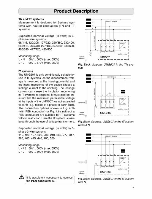
TN and TT systemsMeasurement is designed for 3-phase sys-tems with neutral conductors (TN and TT systems).
Supported nominal voltage (in volts) in 3- phase-4-wire systems:66/115, 120/208, 127/220, 220/380, 230/400, 240/415, 260/440, 277/480, 347/600, 380/660, 400/690, 417/720, 480/830
Measuring range:L - N 50V .. 500V (max. 550V)L - L 90V .. 870V (max. 950V)
Fig. Block diagram, UMG507 in the TN sys-tem.
Fig. Block diagram, UMG507 in the IT system with N.
Fig. Block diagram, UMG507 in the IT system without N.
IT systemsThe UMG507 is only conditionally suitable for use in IT systems, as the measurement volt-age is measured at the housing potential and the input impedence of the device causes a leakage current to the earthing. The leakage current can cause the insulation monitoring in IT systems to respond. It must also be en-sured that the maximum permissible voltage at the inputs of the UMG507 are not exceeded to earth (e.g. in case of a phase-to-earth fault).The connection options shown in Fig. 4.1b (with PEN conductor) or Fig. 4.6a (without a PEN conductor) are suitable for IT systems without restriction. Here the IT system is insu-lated through the use of voltage transformers.
Supported nominal voltage (in volts) in 3- phase-3-wire systems:115, 120, 127, 220, 230, 240, 260, 277, 347, 380, 400, 415, 440, 480, 500.
Measuring range:L - PE 50V .. 500V (max. 550V)L - L 90V .. 500V (max. 550V)
It is absolutely necessary to connect the PEN conductor N.
m
Product Description
UMG507System earthing
DC
AC/DC
230/400V 50/60HzL2
L3
L1
auxiliary power
voltage measurement
4M 4M 4M 4M
PE
Impedance
L1 L3L2 N
UMG507System earthing
DC
AC/DC
500V 50/60HzL2
L3
L1
auxiliary power
voltage measurement
4M 4M 4M 4M
PE
Impedance
PE
- L
m
ax. 5
00V
L1 L3L2 N
UMG507System earthing
DC
AC/DC
PE
230/400V 50/60HzL2
L3
N
L1
auxiliary power
voltage measurement
4M 4M 4M 4M
PE
PE
- L
m
ax. 5
00V
L1 L3L2 N
8
Installation locationThe UMG507 is intended for permanent in-stallation in low and medium-voltage switch-gear. It can be installed in any position.
Protective conductorA protective conductor according to the valid safety regulations must be connected at the screw provided on the rear of the device before the remaining connections with the device can be made.
Supply voltageAn operating voltage is required to run the UMG507. The type and strength of the operat-ing voltage required for the UMG507 is noted on the rating plate. 230V Standard version 120V Special version 63V Special versionHigher voltages between the terminals 31/32 and earth (PE) can severely damage the UMG507. In order to prevent an overvoltage the operating voltage should be earthed.The operating voltage is connected at ter-minals 31 and 32. A maximum voltage of 300VAC may occur between the terminals 31 and 32 (operating voltage) and earth (PE).
Attention!- The wiring cables for the operating voltage must be suitable for nominal voltages up to 300VAC to earth.
- The operating voltage must be fused. The fuse must lie within the range from 2A to 10A.
- The building installation must include a switch or circuit-breaker for the operating voltage.
- The switch must be installed close to the device and be easy for the user to reach.
- The switch must be labelled as a discon-necting device for this device.
- Before applying the operating voltage ensure that the voltage and frequency comply to the values given on the rating plate!
- The device may only be run with an earthed housing!
- Conductors with soldered individual wires are not suitable for connections at screw-type terminals!
-The pluggable screw terminals may only be plugged in when no voltage is applied.
- Only pluggable screw terminals with the same number of poles and the same type (with/without threaded connection) may be connected with each other.
Voltages which lie above the permis-sible voltage range can severely dam-age the device.
m
Installation
9
Installation
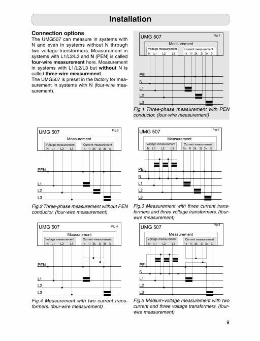
Fig.1 Three-phase measurement with PEN conductor. (four-wire measurement)
Fig.4 Measurement with two current trans-formers. (four-wire measurement)
Fig.3 Measurement with three current trans-formers and three voltage transformers. (four-wire measurement)
Fig.2 Three-phase measurement without PEN conductor. (four-wire measurement)
Fig.5 Medium-voltage measurement with two current and three voltage transformers. (four-wire measurement)
Connection optionsThe UMG507 can measure in systems with N and even in systems without N through two voltage transformers. Measurement in systems with L1/L2/L3 and N (PEN) is called four-wire measurement here. Measurement in systems with L1/L2/L3 but without N is called three-wire measurement. The UMG507 is preset in the factory for mea-surement in systems with N (four-wire mea-surement).
63V Special versionH
5
10
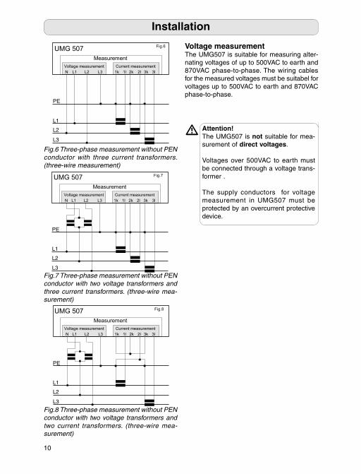
Voltage measurementThe UMG507 is suitable for measuring alter-nating voltages of up to 500VAC to earth and 870VAC phase-to-phase. The wiring cables for the measured voltages must be suitabel for voltages up to 500VAC to earth and 870VAC phase-to-phase.
Attention! The UMG507 is not suitable for mea-surement of direct voltages.
Voltages over 500VAC to earth must be connected through a voltage trans-former .
The supply conductors for voltage measurement in UMG507 must be protected by an overcurrent protective device.
m
Installation
Fig.6 Three-phase measurement without PEN conductor with three current transformers. (three-wire measurement)
Fig.7 Three-phase measurement without PEN conductor with two voltage transformers and three current transformers. (three-wire mea-surement)
Fig.8 Three-phase measurement without PEN conductor with two voltage transformers and two current transformers. (three-wire mea-surement)
11
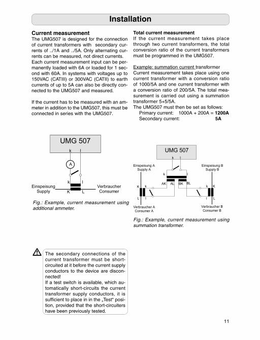
Total current measurementIf the current measurement takes place through two current transformers, the total conversion ratio of the current transformers must be programmed in the UMG507.
Example: summation current transformerCurrent measurement takes place using one current transformer with a conversion ratio of 1000/5A and one current transformer with a conversion ratio of 200/5A. The total mea-surement is carried out using a summation transformer 5+5/5A.The UMG507 must then be set as follows: Primary current: 1000A + 200A = 1200A Secondary current: 5A
Fig.: Example, current measurement using summation transformer.
The secondary connections of the current transformer must be short-circuited at it before the current supply conductors to the device are discon-nected!If a test switch is available, which au-tomatically short-circuits the current transformer supply conductors, it is suffi cient to place in in the „Test“ posi-tion, provided that the short-circuiters have been previously tested.
m
Fig.: Example, current measurement using additional ammeter.
Current measurementThe UMG507 is designed for the connection of current transformers with secondary cur-rents of ../1A and ../5A. Only alternating cur-rents can be measured, not direct currents.Each current measurement input can be per-manently loaded with 6A or loaded for 1 sec-ond with 60A. In systems with voltages up to 150VAC (CATIII) or 300VAC (CATII) to earth currents of up to 5A can also be directly con-nected to the UMG507 and measured.
If the current has to be measured with an am-meter in addition to the UMG507, this must be connected in series with the UMG507.
Installation
12
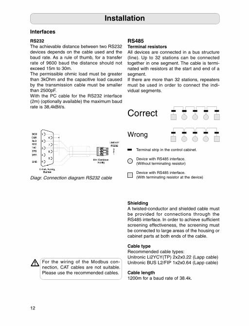
RS485Terminal resistorsAll devices are connected in a bus structure (line). Up to 32 stations can be connected together in one segment. The cable is termi-nated with resistors at the start and end of a segment. If there are more than 32 stations, repeaters must be used in order to connect the indi-vidual segments.
ShieldingA twisted-conductor and shielded cable must be provided for connections through the RS485 interface. In order to achieve suffi cient screening effectiveness, the screening must be connected to large areas of the housing or cabinet parts at both ends of the cable.
Cable typeRecommended cable types:Unitronic Li2YCY(TP) 2x2x0.22 (Lapp cable)Unitronic BUS L2/FIP 1x2x0.64 (Lapp cable)
Cable length1200m for a baud rate of 38.4k.
Installation
Correct
Wrong
Terminal strip in the control cabinet.
Device with RS485 interface.(Without terminating resistor)
Device with RS485 interface. (With terminating resistor at the device)
RS232The achievable distance between two RS232 devices depends on the cable used and the baud rate. As a rule of thumb, for a transfer rate of 9600 baud the distance should not exceed 15m to 30m.The permissible ohmic load must be greater than 3kOhm and the capacitive load caused by the transmission cable must be smaller than 2500pF. With the PC cable for the RS232 interface (2m) (optionally available) the maximum baud rate is 38,4kBit/s.
Interfaces
Diagr. Connection diagram RS232 cable
For the wiring of the Modbus con-nection, CAT cables are not suitable. Please use the recommended cables.
m
13
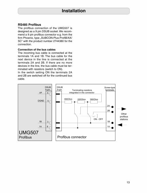
RS485 Profi busThe profi bus connection of the UMG507 is designed as a 9 pin DSUB socket. We recom-mend a 9 pin profi bus connector e.g. from the fi rm Phoenix, type „SUBCON-Plus-Profi B/AX/SC“ with the product number 2744380 for the connection.
Installation
Connection of the bus cablesThe incoming bus cable is connected at the terminals 1A and 1B. The bus cable for the next device in the line is connected at the terminals 2A and 2B. If there are no more devices in the line, the bus cable must be ter-minated with resistors (switch to ON). In the switch setting ON the terminals 2A and 2B are switched off for the continued bus cable.
Otherprofi bus stations
14
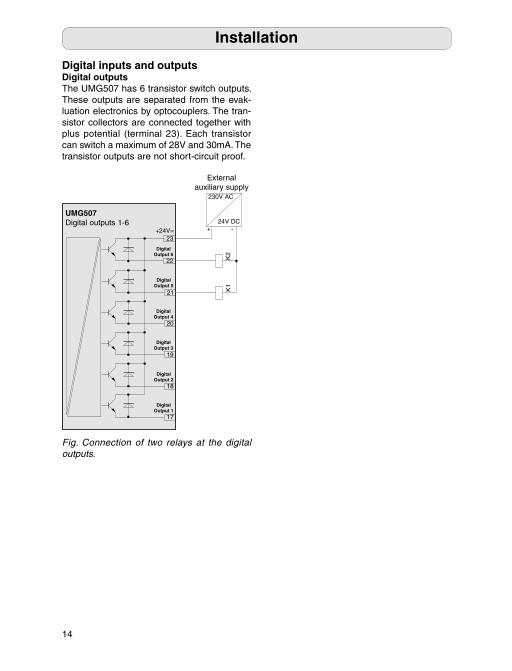
Fig. Connection of two relays at the digital outputs.
Digital inputs and outputsDigital outputsThe UMG507 has 6 transistor switch outputs. These outputs are separated from the evak-luation electronics by optocouplers. The tran-sistor collectors are connected together with plus potential (terminal 23). Each transistor can switch a maximum of 28V and 30mA. The transistor outputs are not short-circuit proof.
+24V=23
22
DigitalOutput 6
UMG507Digital outputs 1-6
K1
K2
+ -
230V AC
24V DC
External auxiliary supply
18
DigitalOutput 2
17
DigitalOutput 1
21
DigitalOutput 5
20
DigitalOutput 4
19
DigitalOutput 3
Installation
15
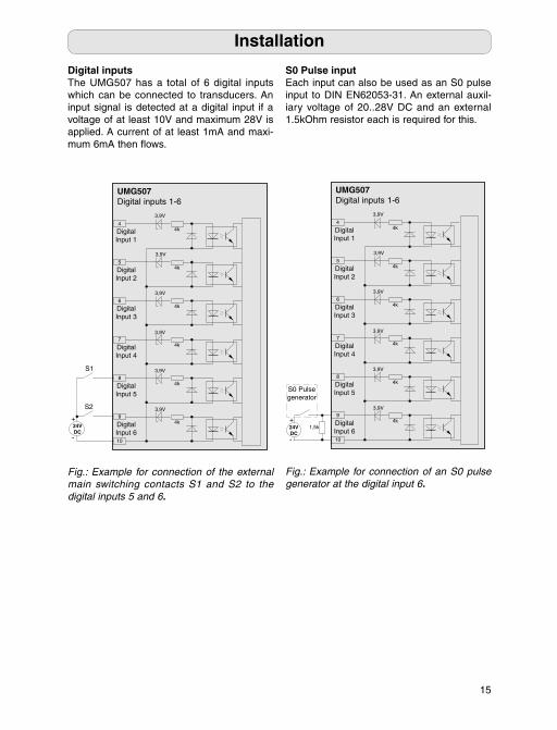
S0 Pulse inputEach input can also be used as an S0 pulse input to DIN EN62053-31. An external auxil-iary voltage of 20..28V DC and an external 1.5kOhm resistor each is required for this.
Fig.: Example for connection of an S0 pulse generator at the digital input 6.
3,9V
4k4
DigitalInput 1
UMG507Digital inputs 1-6
3,9V
3,9V
4k5
DigitalInput 2
3,9V
4k6
DigitalInput 3
4k7
DigitalInput 4
4k8
DigitalInput 5
3,9V
3,9V
4k9
10
DigitalInput 6
S0 Pulse generator
1,5k+
-
24VDC
Installation
Digital inputsThe UMG507 has a total of 6 digital inputs which can be connected to transducers. An input signal is detected at a digital input if a voltage of at least 10V and maximum 28V is applied. A current of at least 1mA and maxi-mum 6mA then fl ows.
Fig.: Example for connection of the external main switching contacts S1 and S2 to the digital inputs 5 and 6.
3,9V
4k4
DigitalInput 1
UMG507Digital inputs 1-6
3,9V
24VDC
+
-
S2
3,9V
4k5
DigitalInput 2
3,9V
4k6
DigitalInput 3
4k7
DigitalInput 4
4k8
DigitalInput 5
3,9V
3,9V
4k9
10
DigitalInput 6
S1
16
Installation
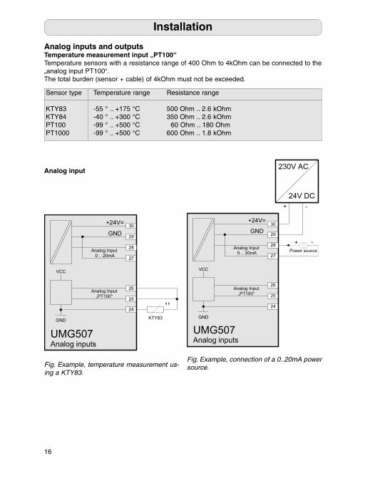
Analog inputs and outputsTemperature measurement input „PT100“Temperature sensors with a resistance range of 400 Ohm to 4kOhm can be connected to the „analog input PT100“. The total burden (sensor + cable) of 4kOhm must not be exceeded.
Analog input
Fig. Example, temperature measurement us-ing a KTY83.
Fig. Example, connection of a 0..20mA power source.
Sensor type Temperature range Resistance range
KTY83 -55 ° .. +175 °C 500 Ohm .. 2.6 kOhmKTY84 -40 ° .. +300 °C 350 Ohm .. 2.6 kOhmPT100 -99 ° .. +500 °C 60 Ohm .. 180 OhmPT1000 -99 ° .. +500 °C 600 Ohm .. 1.8 kOhm
17
Installation
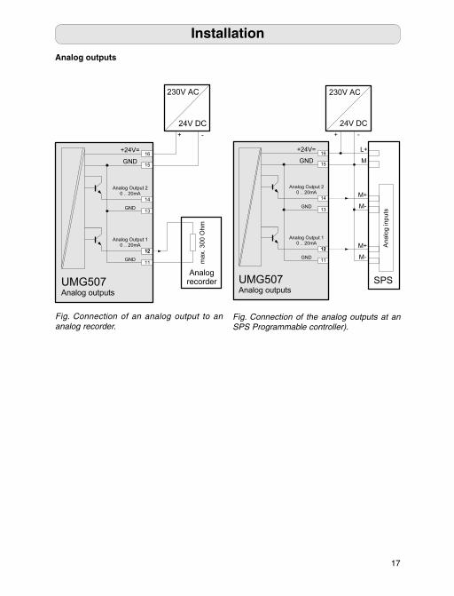
Fig. Connection of an analog output to an analog recorder.
Analog outputs
Fig. Connection of the analog outputs at an SPS Programmable controller).
Temperature range Resistance range
K -55 ° .. +175 °C 500 Ohm .. 2.6 kOhmK -40 ° .. +300 °C 350 Ohm .. 2.6 kOhmP -99 ° .. +500 °C 60 Ohm .. 180 OhmP -99 ° .. +500 °C 600 Ohm .. 1.8 kOhm

A
A
A
A
press briefl press continuously
2
Return to the fi rst measured value- display (panel)
P Panel left
P Panel down
E press briefl press continuously
2
previous digit
N Number / 10
D Digit - 1
S
18
Apply measurement currentThe UMG507 is designed for the connection of ../1A and ../5A current transformers. Only alternating currents can be measured through the current measurement inputs, not alternating currents. Current transformer terminals must be earthed on the secondary side. Current transformers which are not loaded on the secondary side can result in dangerous contact voltages and must therefore be short-circuited.Connect the individual current transformers to the UMG50 and compare the current dis-played with the applied current. The current displayed by the UMG507 must correspond to the input current, taking into account the current transformer transformation ratio. The current transformer rator is set in the fac-tory to 5/5A and may have to be adapted to the current transformers used. If the current transformer is short-circuited on the secondary side, the UMG507 must display approx. zero amperes in the corresponding external conductor.
Install deviceThe UMG507 is intended for installation in low-voltage distribution boards, in which maxi-mum overvoltages in the overvoltage category III occur. It can be installed in any position. The en-closed fi xing branckets are to be used in the front panels or switchgear cabinet doors.
Connect deviceApply supply voltageThe size of the measuring and operating volt-age for the UMG507 is given on the rating plate. Measurement and operating voltages, which do not correspond to the values given on the rating plate, malfunctions and severe damage to the device can result.The wiring cables for the measuring voltages to the UMG507 must be suitable for voltages up to 300V to earth and 520V phase-to-phase.After switching on the measuring and operat-ing voltage specifi ed on the rating plate of the UMG507, all the segments appear in the display. About two seconds later the UMG507 switches to the fi rst measured value display.If no display appears, check whether the op-erating voltage lies within the nominal voltage range.
Initial Startup
Apply measurement voltageThe UMG507 is suitable for the measurement of voltages of up to 500VAC to earth and 870VAC phase-to-phase. The UMG507 is not suitable for the measure-ment of direct voltages. Voltages over 500VAC to earth must be connected through voltage transformers. After connecting the measurement voltage, the measured values for the voltages L-N and L-L displayed by the UMG507 must be compared with those at the voltage measure-ment input. If a voltage transformer factor is programmed, this must be taken into account in the comparison.
19
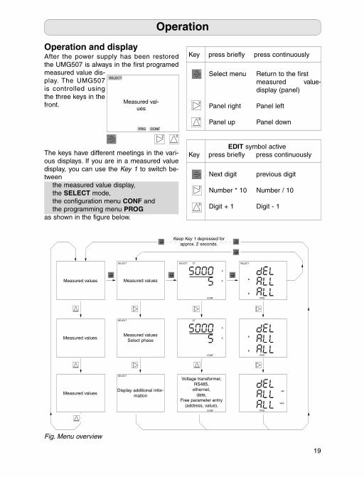
Operation and display After the power supply has been restored the UMG507 is always in the fi rst programed measured value dis-play. The UMG507 is controlled using the three keys in the front.
The keys have different meetings in the vari-ous displays. If you are in a measured value display, you can use the Key 1 to switch be-tween the measured value display, the SELECT mode, the confi guration menu CONF and the programming menu PROGas shown in the fi gure below.
Fig. Menu overview
Operation
Keep Key 1 depressed for approx. 2 seconds.
PRG
SELECT
Voltage transformer,RS485,
ethernet,date,
Free parameter entry (address, value).
CONF
CONF
A
A
SELECT CT
CONF
A
A
CT
SELECT
Measured values
SELECT
Display additional infor-mation
SELECT
Measured valuesSelect phase
Measured values
Measured values
Measured values
PRG
PRG
Wh
VArh
Key press briefl y press continuously
2
1
3
Select menu Return to the fi rst measured value- display (panel)
Panel right Panel left
Panel up Panel down
EDIT symbol activeKey press briefl y press continuously
2
1
3
Next digit previous digit
Number * 10 Number / 10
Digit + 1 Digit - 1
SELECT
PRG CONF
Measured val-ues
1 2 3
20
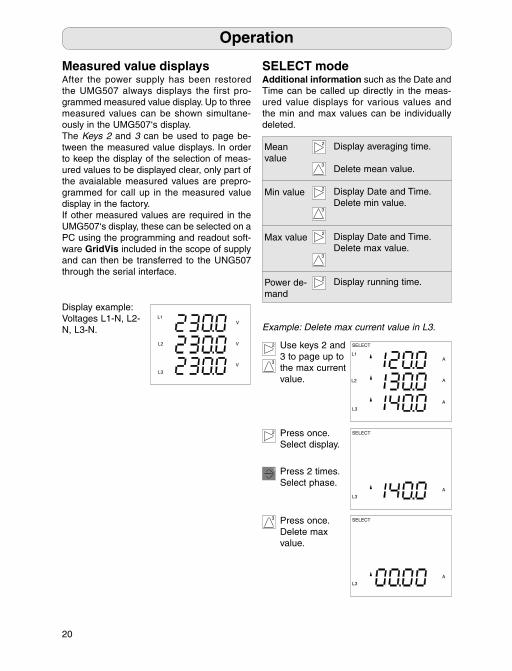
SELECT modeAdditional information such as the Date and Time can be called up directly in the meas-ured value displays for various values and the min and max values can be individually deleted.
Measured value displaysAfter the power supply has been restored the UMG507 always displays the first pro-grammed measured value display. Up to three measured values can be shown simultane-ously in the UMG507‘s display. The Keys 2 and 3 can be used to page be-tween the measured value displays. In order to keep the display of the selection of meas-ured values to be displayed clear, only part of the avaialable measured values are prepro-grammed for call up in the measured value display in the factory. If other measured values are required in the UMG507‘s display, these can be selected on a PC using the programming and readout soft-ware GridVis included in the scope of supply and can then be transferred to the UNG507 through the serial interface.
Display example: Voltages L1-N, L2-N, L3-N.
Operation
V
V
V
L3
L1
L2
2
3
Mean value
Min value
Max value
Power de-mand
Display averaging time. Delete mean value.
Display Date and Time.Delete min value.
Display Date and Time.Delete max value.
Display running time.
2
3
2
3
2
2
3
Example: Delete max current value in L3.
1
Use keys 2 and 3 to page up to the max current value.
Press 2 times.Select phase.
2 Press once.Select display.
3 Press once.Delete max value.
L1
SELECT
L2
L3
A
A
A
SELECT
L3
A
SELECT
L3
A
21
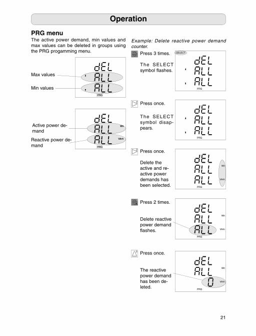
PRG menuThe active power demand, min values and max values can be deleted in groups using the PRG progamming menu.
Min valuesPRG
PRG
Wh
VArh
Active power de-mand
Operation
Max values
Reactive power de-mand
Press once.
Delete the active and re-active power demands has been selected.
3
1 Press 3 times.
The SELECT symbol fl ashes.
2 Press once.
SELECT
PRG
The SELECT symbol disap-pears.
Example: Delete reactive power demand counter.
Press once.
The reactive power demand has been de-leted.
2
PRG
PRG
VArh
Wh
Press 2 times.
Delete reactive power demand fl ashes.
PRG
VArh
Wh
1
PRG
VArh
Wh
A
= Characters very dark
F 20
C
22
2
Operation
A
CT
A
CONF
VT
V
V
CONF
ADDR
CONF
k
CONF CONF
CONF
CONF
CONF
Y.M
D.H
M.S
CONF
CONF
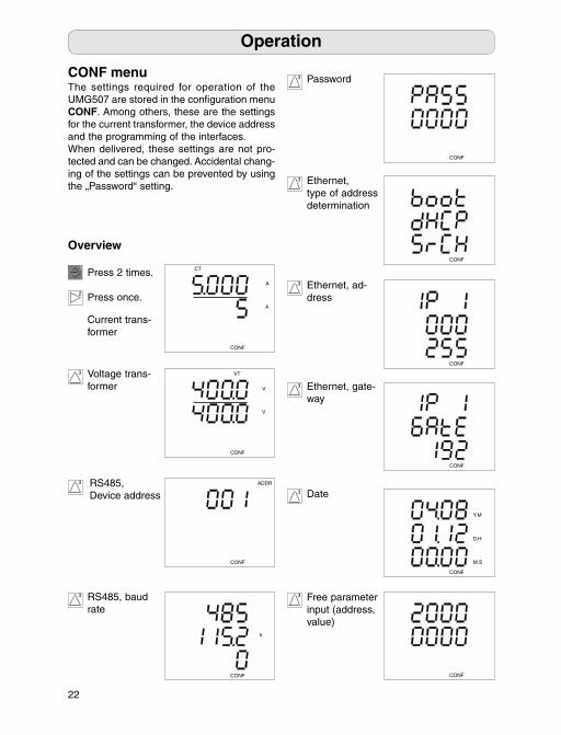
CONF menuThe settings required for operation of the UMG507 are stored in the confi guration menu CONF. Among others, these are the settings for the current transformer, the device address and the programming of the interfaces.When delivered, these settings are not pro-tected and can be changed. Accidental chang-ing of the settings can be prevented by using the „Password“ setting.
3
1Press 2 times.
Press once.
Current trans-former
Voltage trans-former
3
3 RS485, Device address
RS485, baud rate
Password
Ethernet, type of address determination
Ethernet, ad-dress
Ethernet, gate-way
Date
Free parameter input (address, value)
3
3
3
3
3
3
Overview
23
Confi guration
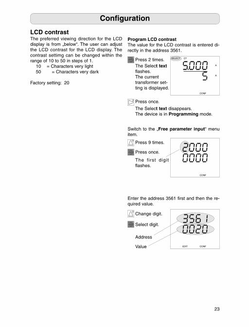
LCD contrastThe preferred viewing direction for the LCD display is from „below“. The user can adjust the LCD contrast for the LCD display. The contrast settimg can be changed within the range of 10 to 50 in steps of 1. 10 = Characters very light 50 = Characters very dark
Factory setting: 20
CONFEDIT
1 Press 2 times.The Select text fl ashes.The current transformer set-ting is displayed.
1 Press once.
The f irst digit fl ashes.
Program LCD contrast The value for the LCD contrast is entered di-rectly in the address 3561.
SELECT CT
CONF
A
A
2 Press once.
The Select text disappears.The device is in Programming mode.
3 Press 9 times.
Switch to the „Free parameter input“ menu item.
Enter the address 3561 fi rst and then the re-quired value.
Change digit.3
Select digit.1
Address
Value
CONF
5
Currentt
Primary 1A .. 999.9MA 5AS 5A
2
24
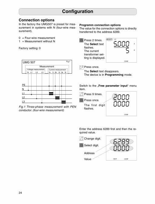
Connection optionsIn the factory the UMG507 is preset for mea-surement in systems with N (four-wire mea-surement).
0 = Four-wire measurement1 = Measurement without N
Factory setting: 0
Confi guration
1 Press 2 times.The Select text fl ashes.The current transformer set-ting is displayed.
1 Press once.
The f irst digit fl ashes.
Programm connection optionsThe value for the connection options is directly transferred to the address 6289.
SELECT CT
CONF
A
A
2 Press once.
The Select text disappears.The device is in Programming mode.
3 Press 9 times.
Switch to the „Free parameter input“ menu item.
Enter the address 6289 fi rst and then the re-quired value.
Change digit.3
Select digit.1
Address
Value
CONF
CONFEDIT
Fig.1 Three-phase measurement with PEN conductor. (four-wire measurement)
25
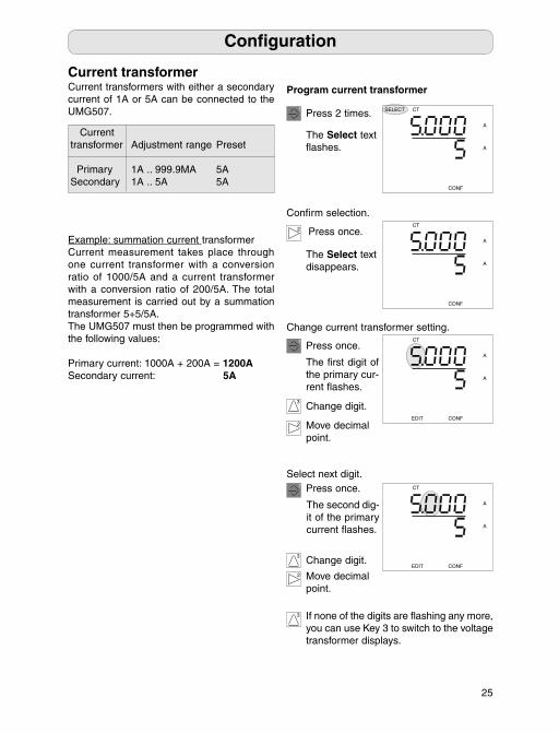
Current transformerCurrent transformers with either a secondary current of 1A or 5A can be connected to the UMG507.
Example: summation current transformerCurrent measurement takes place through one current transformer with a conversion ratio of 1000/5A and a current transformer with a conversion ratio of 200/5A. The total measurement is carried out by a summation transformer 5+5/5A. The UMG507 must then be programmed with the following values:
Primary current: 1000A + 200A = 1200ASecondary current: 5A
Program current transformer
Currenttransformer Adjustment range Preset
Primary 1A .. 999.9MA 5ASecondary 1A .. 5A 5A
2
1 Press 2 times.
Confi rm selection.
Press once.
SELECT CT
CONF
A
A
The Select text fl ashes.
CT
CONF
A
A
The Select text disappears.
2
1
3
Press once.
The fi rst digit of the primary cur-rent fl ashes.
Change digit.
Change current transformer setting.
1
Select next digit.Press once.
The second dig-it of the primary current fl ashes.
2
Change digit.EDIT
CT
CONF
A
A
EDIT
CT
CONF
A
A
3
Move decimal point.
Move decimal point.
If none of the digits are fl ashing any more, you can use Key 3 to switch to the voltage transformer displays.
3
Confi guration
001 ... 247
T
000 ... 126
T
26
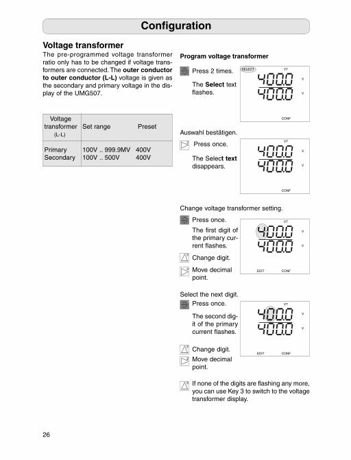
Voltage transformerThe pre-programmed voltage transformer ratio only has to be changed if voltage trans-formers are connected. The outer conductor to outer conductor (L-L) voltage is given as the secondary and primary voltage in the dis-play of the UMG507.
Program voltage transformer
2
1 Press 2 times.
Auswahl bestätigen.
Press once.
The Select text fl ashes.
The Select text disappears.
2
1
3
Press once.
The fi rst digit of the primary cur-rent fl ashes.
Change digit.
Change voltage transformer setting.
1
Select the next digit.Press once.
The second dig-it of the primary current fl ashes.
2
Change digit.
3
Move decimal point.
Move decimal point.
If none of the digits are fl ashing any more, you can use Key 3 to switch to the voltage transformer display.
3
SELECT VT
CONF
V
V
VT
EDIT CONF
V
V
VT
CONF
V
V
VT
EDIT CONF
V
V
Voltage transformer Set range Preset (L-L)
Primary 100V .. 999.9MV 400VSecondary 100V .. 500V 400V
Confi guration

27
Confi guration
Network settingEach device in a system must have its own address. The ethernet and RS485 are in-dependent systems and have their own ad-dresses.
RS485Modbus protocolAddress setting range for use of the Modbus protocol: 001 ... 247
The factory setting for the address is 001.
ADDR
CONF
RS485 Network ad-dress = 1
Program network address
1 Press 2 times.The Select text fl ashes.The current transformer set-ting is displayed.
The current net-work address is displayed
2 Press once.
The Select text disappears.The device is in Programming mode.
3 Press 2 times.
Switch to the „Network address“ menu item.
Change network address.
Change digit.3
Press once.
The fi rst digit fl ashes.
1
ADDR
CONF
1 Select digit.
ADDR
EDIT CONF
CT
CONF
A
A
CONF
k
Interface
Baud rate
transfer protocols:0=Modbus slave1=Modbus master2=Profi bus
Profi bus protocolAddress setting range for use of the Profi bus protocol: 000 ... 126
The factory setting for the address is 001.
Set range Preset
100V .. 999.9MV 400VS 400V
C
28
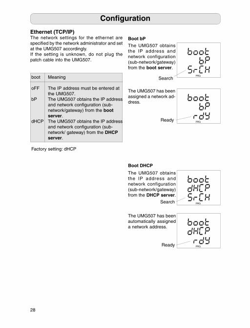
Ethernet (TCP/IP)The network settings for the ethernet are specifi ed by the network administrator and set at the UMG507 accordingly.If the setting is unknown, do not plug the patch cable into the UMG507.
Boot DHCP
Boot bP
PRG
PRG
PRG
PRG
Confi guration
boot Meaning
oFF The IP address must be entered at the UMG507.bP The UMG507 obtains the IP address and network confi guration (sub- network/gateway) from the boot server.dHCP The UMG507 obtains the IP address and network confi guration (sub- network/ gateway) from the DHCP server.
Factory setting: dHCP
The UMG507 obtains the IP address and network configuration (sub-network/gateway) from the DHCP server.
The UMG507 obtains the IP address and network configuration (sub-network/gateway) from the boot server.
The UMG507 has been automatically assigned a network address.
The UMG507 has been assigned a network ad-dress.
Search
Ready
Search
Ready
29
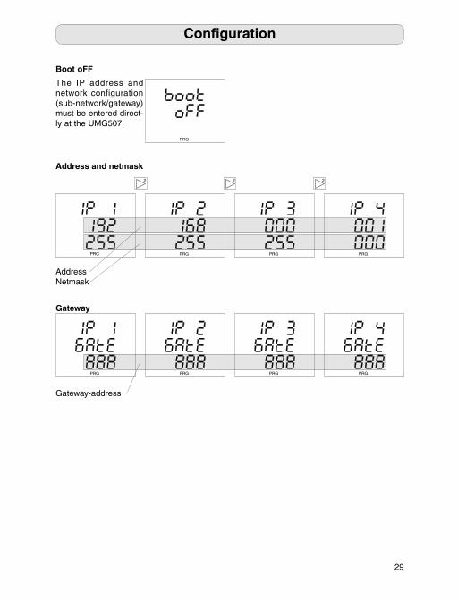
Address and netmask
Confi guration
PRG
Boot oFF
The IP address and network configuration (sub-network/gateway) must be entered direct-ly at the UMG507.
2 2
PRGPRG PRG PRG
2
AddressNetmask
Gateway
PRG PRGPRG PRG
Gateway-address
The IP address must be entered at the U
The UMG507 obtains the IP address and network confi guration (sub- network/gateway) from the b server.
T and network confi guration (sub- network/ gateway) from the D server.
30
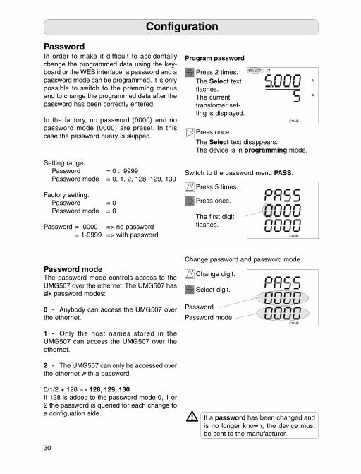
PasswordIn order to make it difficult to accidentally change the programmed data using the key-board or the WEB interface, a password and a password mode can be programmed. It is only possible to switch to the pramming menus and to change the programmed data after the password has been correctly entered.
In the factory, no password (0000) and no password mode (0000) are preset. In this case the password query is skipped.
If a password has been changed and is no longer known, the device must be sent to the manufacturer.
m
Setting range: Password = 0 .. 9999 Password mode = 0, 1, 2, 128, 129, 130 Factory setting: Password = 0 Password mode = 0
Password = 0000 => no password = 1-9999 => with password
Confi guration
Password modeThe password mode controls access to the UMG507 over the ethernet. The UMG507 has six password modes:
0 - Anybody can access the UMG507 over the ethernet.
1 - Only the host names stored in the UMG507 can access the UMG507 over the ethernet.
2 - The UMG507 can only be accessed over the ethernet with a password.
0/1/2 + 128 => 128, 129, 130If 128 is added to the password mode 0, 1 or 2 the password is queried for each change to a confi guation side.
Password mode
CONF
1 Press 2 times.The Select text fl ashes.The current transfomer set-ting is displayed.
1 Press once.
The fi rst digit fl ashes.
Program password
SELECT CT
CONF
A
A
2 Press once.
The Select text disappears.The device is in programming mode.
3 Press 5 times.
Switch to the password menu PASS.
Change password and password mode.
Change digit.3
Select digit.1
CONF
Password

31
= 0 .. 9999
= 0 = 0
P 0000 => no password = 1-9999 => with password
C
32
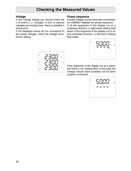
VoltageIn the voltage display you should check the L-N and/or L-L voltages. If one or several voltages are missing here, there is possibly a wiring error. If the displayed values do not correspond to the actual voltages, check the voltage trans-former setting.
Phase sequenceIf all the voltage circuits have been connected, the UMG507 displays the phase sequence.If all the segments in the display run in a clockwise direction, a right-hand rotating fi eld exists. If the segments in the display run in an anti-clockwise direction, a left-hand rotating fi eld exists.
Checking the Measured Values
L1
Hz
L1
Hz
L1
L3
L2
V
V
V
If the segments in the display are at a stand-still there is not rotating fi eld. In this case the voltage circuits have probably not all been properly connected.
33
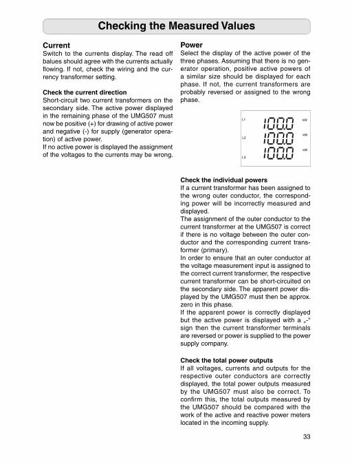
PowerSelect the display of the active power of the three phases. Assuming that there is no gen-erator operation, positive active powers of a similar size should be displayed for each phase. If not, the current transformers are probably reversed or assigned to the wrong phase.
Check the total power outputsIf all voltages, currents and outputs for the respective outer conductors are correctly displayed, the total power outputs measured by the UMG507 must also be correct. To confi rm this, the total outputs measured by the UMG507 should be compared with the work of the active and reactive power meters located in the incoming supply.
Check the individual powersIf a current transformer has been assigned to the wrong outer conductor, the correspond-ing power will be incorrectly measured and displayed. The assignment of the outer conductor to the current transformer at the UMG507 is correct if there is no voltage between the outer con-ductor and the corresponding current trans-former (primary).In order to ensure that an outer conductor at the voltage measurement input is assigned to the correct current transformer, the respective current transformer can be short-circuited on the secondary side. The apparent power dis-played by the UMG507 must then be approx. zero in this phase.If the apparent power is correctly displayed but the active power is displayed with a „-“ sign then the current transformer terminals are reversed or power is supplied to the power supply company.
Checking the Measured Values
L1
L2
L3
kW
kW
kW
CurrentSwitch to the currents display. The read off balues should agree with the currents actually fl owing. If not, check the wiring and the cur-rency transformer setting.
Check the current directionShort-circuit two current transformers on the secondary side. The active power displayed in the remaining phase of the UMG507 must now be positive (+) for drawing of active power and negative (-) for supply (generator opera-tion) of active power.If no active power is displayed the assignment of the voltages to the currents may be wrong.
07:00h to 15:00h 07:00h to 12:00h
J
Tel. (
Fax (0 64 41) 9642-30 e-mail:
34
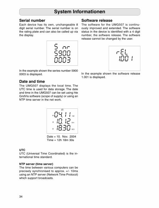
Software releaseThe software for the UMG507 is continu-ously improved and extended. The software status in the device is identifi ed with a 4 digit number, the software release. The software release cannot be changed by the user.
Serial numberEach device has its own, unchangeable 8 digit serial number. The serial number is on the rating plate and can also be called up via the display.
System Informationen
Date and timeThe UMG507 displays the local time. The UTC time is used for data storage. The date and time in the UMG507 can be set using hte GridVis software (scope of supply) or using an NTP time server in the net work.
Y.M
D.H
M.S
Date = 10. Nov. 2004Time = 12h 18m 30s
In the example shown the series number 5900 0003 is displayed. In the example shown the software release
1.001 is displayed.
UTCUTC (Universal Time Coordinated) is the in-ternational time standard.
NTP server (time server)The time between various computers can be precisely synchronised to approx. +/- 10ms using an NTP server (Network Time Protocol) which support broadcasts.
35
ServiceIf questions arise, which are not described in this manual, please contact us directly.In order to deal with questions, we will need the following information: - Device designation (see rating plate), - Serial number (see rating plate), - Auxiliary voltage (see rating plate), - Software release (display) and - Precise description of the error.
You can contact us: Mo to Th 07:00h to 15:00h Fr 07:00h to 12:00h
Janitza electronics GmbHVor dem Polstück 1D-35633 LahnauSupport: Tel. (0 64 41) 9642-22 Fax (0 64 41) 9642-30 e-mail: [email protected]
MaintenanceThe device is subjected to various safety tests before being delivered and is marked with a seal. If a device is opened the safety tests must be repeated. We only provide a warranty for unopened devices.
Repair and calibrationRepair and calibration work can only be car-ried out in the manufacturing factory.
Front foilThe front foil can be cleaned with a soft cloth and the usual domestic cleaning agents. Never use acids or cleaning agents containing acids to clean the device.
BatteryThe life expectancy of the battery at a storage temperature of +45°C is at least 5 years. The typical life expectancy of the battery is 8 to 10 years. The battery (type CR2450N 3V/540mAh) can be replaced by the user.
Service and Maintenance
DisposalThe device can be disposed of as electronic scrap in accordance with the legal provisions for recycling. The lithium battery installed must be disposed of separately.
V
Current circuit is
a
R
36
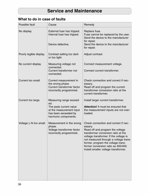
Possible fault
No display.
Poorly legible display.
No current display.
Current too small.
Current too large.
Voltage L-N too small.
Cause
External fuse has tripped. Internal fuse has tripped.
Device defective.
Contrast setting too dark or too light.
Measuring voltage not connected.Current transformer not connected.
Current measurement in the wrong phase. Current transformer factor incorrectly programmed.
Measuring range exceed-ed.The peak current value at the measurement input has been exceeded by harmonic components.
Measurement in the wrong phase. Voltage transformer factor incorrectly programmed.
Remedy
Replace fuse.Fuse cannot be replaced by the user. Send the device to the manufacturer for repair.Send the device to the manufacturer for repair.
Adjust contrast.
Connect measurement voltage.
Connect current transformer.
Check connection and correct if nec-essary. Read off and program the current transformer conversion ratio at the current transformer.
Install larger current transformer.
Attention! It must be ensured that the measurement inputs are not over-loaded.
Check connection and correct if nec-essary.Read off and program the voltage transformer conversion ratio at the voltage transformer. If the voltage is not measured through a voltage trans-former, program the voltage trans-former conversion ratio as 400/400.Install smaller voltage transformer.
What to do in case of faults
Service and Maintenance
37
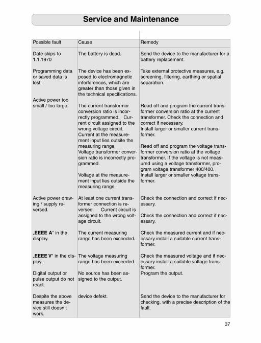
Possible fault
Date skips to 1.1.1970
Programming data or saved data is lost.
Active power too small / too large.
Active power draw-ing / supply re-versed.
„EEEE A“ in the display.
„EEEE V“ in the dis-play.
Digital output or pulse output do not react.
Despite the above measures the de-vice still doesn‘t work.
Cause
The battery is dead.
The device has been ex-posed to electromagnetic interferences, which are greater than those given in the technical specifi cations.
The current transformer conversion ratio is incor-rectly programmed. Cur-rent circuit assigned to the wrong voltage circuit.Current at the measure-ment input lies outsite the measuring range.Voltage transformer conver-sion ratio is incorrectly pro-grammed.
Voltage at the measure-ment input lies outside the measuring range.
At least one current trans-former connection is re-versed. Current circuit is assigned to the wrong volt-age circuit.
The current measuring range has been exceeded.
The voltage measuring range has been exceeded. No source has been as-signed to the output.
device defekt.
Remedy
Send the device to the manufacturer for a battery replacement.
Take external protective measures, e.g. screening, fi ltering, earthing or spatial separation.
Read off and program the current trans-former conversion ratio at the current transformer. Check the connection and correct if necessary.Install larger or smaller current trans-former.
Read off and program the voltage trans-former conversion ratio at the voltage transformer. If the voltage is not meas-ured using a voltage transformer, pro-gram voltage transformer 400/400.Install larger or smaller voltage trans-former.
Check the connection and correct if nec-essary.
Check the connection and correct if nec-essary.
Check the measured current and if nec-essary install a suitable current trans-former.
Check the measured voltage and if nec-essary install a suitable voltage trans-former.Program the output.
Send the device to the manufacturer for checking, with a precise description of the fault.
Service and Maintenance
C
Annual recalibration. A preheating time of 10 minutes.
with current transformer ../5A : Class 1 with current transformer ../1A : Class 2
M Measurement uncertainties
V 45 .. 65Hz ±(0.2% rdg + 0.02% rng)C 45 .. 65Hz ±(0.2% rdg + 0.05% rng)C 45 .. 65Hz ±(0.6% rdg + 0.05% rng)P 45 .. 65Hz ±0.5°P 45 .. 65Hz ±(0.4% rdg + 0.1% rng F 45 .. 65Hz ±(0.2% rdg + 0.75% rng
T
Crest factor for max. RMS-Measured value
V 50 ... 500Vr 1.1C 0.005 ... 6Ar 1.4
M Measurement u
±2 minutes/month (18°C ... 28 °C)
A
38
Technical Specifi cations
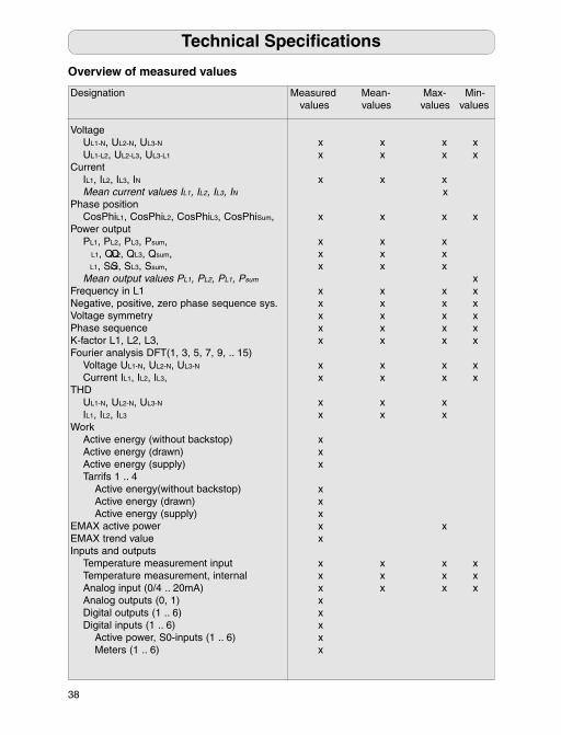
Overview of measured values
Designation Measured Mean- Max- Min- values values values values
Voltage UL1-N, UL2-N, UL3-N x x x x UL1-L2, UL2-L3, UL3-L1 x x x xCurrent IL1, IL2, IL3, IN x x x Mean current values IL1, IL2, IL3, IN xPhase position CosPhiL1, CosPhiL2, CosPhiL3, CosPhiSum, x x x xPower output PL1, PL2, PL3, Psum, x x x QL1, QL2, QL3, Qsum, x x x SL1, SL2, SL3, Ssum, x x x Mean output values PL1, PL2, PL1, Psum xFrequency in L1 x x x xNegative, positive, zero phase sequence sys. x x x xVoltage symmetry x x x xPhase sequence x x x xK-factor L1, L2, L3, x x x xFourier analysis DFT(1, 3, 5, 7, 9, .. 15) Voltage UL1-N, UL2-N, UL3-N x x x x Current IL1, IL2, IL3, x x x xTHD UL1-N, UL2-N, UL3-N x x x IL1, IL2, IL3 x x xWork Active energy (without backstop) x Active energy (drawn) x Active energy (supply) x Tarrifs 1 .. 4 Active energy(without backstop) x Active energy (drawn) x Active energy (supply) x EMAX active power x xEMAX trend value xInputs and outputs Temperature measurement input x x x x Temperature measurement, internal x x x x Analog input (0/4 .. 20mA) x x x x Analog outputs (0, 1) x Digital outputs (1 .. 6) x Digital inputs (1 .. 6) x Active power, S0-inputs (1 .. 6) x Meters (1 .. 6) x
39
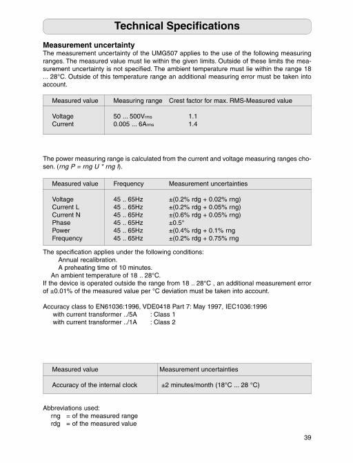
Measurement uncertaintyThe measurement uncertainty of the UMG507 applies to the use of the following measuring ranges. The measured value must lie within the given limits. Outside of these limits the mea-surement uncertainty is not specifi ed. The ambient temperature must lie within the range 18 ... 28°C. Outside of this temperature range an additional measuring error must be taken into account.
The specifi cation applies under the following conditions: Annual recalibration. A preheating time of 10 minutes. An ambient temperature of 18 .. 28°C. If the device is operated outside the range from 18 .. 28°C , an additional measurement error of ±0.01% of the measured value per °C deviation must be taken into account.
Accuracy class to EN61036:1996, VDE0418 Part 7: May 1997, IEC1036:1996 with current transformer ../5A : Class 1 with current transformer ../1A : Class 2
Measured value Frequency Measurement uncertainties
Voltage 45 .. 65Hz ±(0.2% rdg + 0.02% rng)Current L 45 .. 65Hz ±(0.2% rdg + 0.05% rng)Current N 45 .. 65Hz ±(0.6% rdg + 0.05% rng)Phase 45 .. 65Hz ±0.5°Power 45 .. 65Hz ±(0.4% rdg + 0.1% rng Frequency 45 .. 65Hz ±(0.2% rdg + 0.75% rng
The power measuring range is calculated from the current and voltage measuring ranges cho-sen. (rng P = rng U * rng I).
Measured value Measuring range Crest factor for max. RMS-Measured value
Voltage 50 ... 500Vrms 1.1Current 0.005 ... 6Arms 1.4
Measured value Measurement uncertainties
Accuracy of the internal clock ±2 minutes/month (18°C ... 28 °C)
Abbreviations used: rng = of the measured range rdg = of the measured value
Technical Specifi cations
Measured Max- Min- values values values values
V x x x x x x xC x x x
x x xP x x x xF x x x xN x x x xV x x x xP x x x xK x x x xF x x x x x x x xT x x x x xW x x x Active energy(without backstop) x Active energy (drawn) x Active energy (supply) x E x
xI x x x x x x x x x x x x x x x Active power, S0-inputs (1 .. 6) x Meters (1 .. 6) x
: 32V CATI
R : 50Hz 200ms; 60Hz 167ms 6 Maximum counting frequency (S0) : 20Hz Current input : approx 1mA .. 6mA6 Switching voltage : max. 28VDC Switching current : max. 30mA Switching frequency (50Hz system) : max. 2.5Hz Switching frequency (60Hz system) : max. 3Hz Auxiliary voltage, external : 20V .. 28VDC Switching frequency : max. 20Hz Switching current : max. 30mA Max. cable length : 100m Auxiliary voltage, external : 20V .. 28VDC
A : 32V CATI
A : +-1.5% v : 0/4 .. 20mA
: max. 3 : 20V .. 28V DC Residual ripple : max. 2V, 50Hz1 : 0 .. 20mA1 : PT100, PT1000, KTY83, KTY84
I : 32V CATI
: 3-pin s Protocol : Modbus R Transfer rate : 38.4kbps : Connector, SUB D 9-pin Protocol, profi : Profi Transfer rate : 9.6kBaud up to 1.5MBaud Protocoll, Modbus RTU : Modbus RTU/Slave, RTU/Master Transfer rate : 9600bps, 19.2kbps, 38.4kbps, 115.2kbps Connection : RJ-45 : Modbus g : TCP/IP, E Modbus-TCP, Modbus over Ethernet, P
40
Weight : 850gCalorifi c value : 2.2MJ (610Wh)Installed location : anyConnectable conductorsSolid , stranded, fl exible : 0.08 - 2.5mm2Plug connector, wire end ferrule : 1.5mm2 only one conductor may be connected for each terminal connection!
Ambient conditions Operating temperature range : -10°C .. +55°C Storage temperature range : -20°C .. +70°C Relative air humidity : 15% .. 95% without condensation Operating altitude : 0 .. 2000m above sea level
Degree of protection Front : IP50 to IEC529 Front with seal (option) : IP65 to IEC529 Rear : IP20 to IEC529 Pluggable screw terminal : IP20 to IEC529
Auxiliary power (see rating plate) : 300V CATIII Test voltage : 3150V DC Range 1 (standard) : 85 .. 265V AC, 120 .. 370V DC Range 2 (option) : 40 .. 115V AC, 55 .. 165V DC Range 3 (option) : 15 .. 50V AC, 20 .. 70V DC Back-up fuse : 4A .. 10A (medium time lag) Power consumption : max. 5W, max. 9VA
Measurement
Current measurement Overvoltage category : 300V CATII, 150V CATIII Test voltage : 2000V DC Power consumption : approx. 0.2 VA Nominal current for ../5A (../1A) : 5A (1A) Limit current : 9.5A (sinusoidal) Overload, continuous : 6A (sinusoidal) Overload : 60A for 1 sec.
Voltage measurement Overvoltage category : 500V CATIII Test voltage : 4200V DC Impedance : 4MOhm/Phase Power consumption : approx. 0.1 VA Measuring range L-N : 50 .. 500V AC Measuring range L-L : 90 .. 870V AC Frequency of the fundamental component : 45Hz.. 65Hz
Technical Specifi cations
41
Inputs and outputs
Digital inputs and outputsOvervoltage category : 32V CATIRefreshment rate inputs, outputs, fl ags : 50Hz 200ms; 60Hz 167ms 6 Digital inputs Maximum counting frequency (S0) : 20Hz Current input : approx 1mA .. 6mA6 Digital outputs, positive switching (not short-circuit proof) As switching output Switching voltage : max. 28VDC Switching current : max. 30mA Switching frequency (50Hz system) : max. 2.5Hz Switching frequency (60Hz system) : max. 3Hz Auxiliary voltage, external : 20V .. 28VDC As pulse output (S0) Switching frequency : max. 20Hz Switching current : max. 30mA Max. cable length : 100m Auxiliary voltage, external : 20V .. 28VDC
Analog inputs and outputs (options)Overvoltage category : 32V CATIAccuracy : +-1.5% vMb.2 analog outputs : 0/4 .. 20mA Burden : max. 300 Ohm External auxiliary power : 20V .. 28V DC Residual ripple : max. 2V, 50Hz1 analog input „0 .. 20mA“ : 0 .. 20mA1 analog input „PT100“ : PT100, PT1000, KTY83, KTY84
Interfaces (options)Overvoltage category : 32V CATI RS232 : 3-pin screw-plug in terminals. Protocol : Modbus RTU Transfer rate : 38.4kbps RS485 (option) : Connector, SUB D 9-pin Protocol, profi bus (option) : Profi bus DP/V0 to EN 50170 Transfer rate : 9.6kBaud up to 1.5MBaud Protocoll, Modbus RTU : Modbus RTU/Slave, RTU/Master Transfer rate : 9600bps, 19.2kbps, 38.4kbps, 115.2kbps Ethernet 10/100Base-TX (option) Connection : RJ-45 Functions : Modbus gateway, embedded webserver Protocols : TCP/IP, EMAIL(SMTP), DHCP(BootP), Modbus-TCP, Modbus over Ethernet, Ping, NTP.
Technical Specifi cations
Master/Slave operation via RS485 only possible with UMG 96S, UMG 503, UMG 505, Prophi and ProData.
: 850gC : 2.2MJ (
: anyC
: 0.08 - 2.5mm2P : 1.5mm2 only one conductor may be connected for each terminal connection!
A Operating temperature range : -10°C .. +55°C : -20°C .. +70°C : 15% .. 95% without condensation : 0 .. 2000m above sea level
D Front : IP50 to IEC529 Front with seal (option) : IP65 to IEC529 : IP20 t Pluggable screw terminal : IP20 to IEC529
A : 300V CATIII : 3150V D Range 1 (standard) : 85 .. 265V AC, 120 .. 370V DC Range 2 (option) : 40 .. 115V AC, 55 .. 165V DC Range 3 (option) : 15 .. 50V AC, 20 .. 70V DC : 4A .. 10A (medium time lag) : max. 5W, max. 9VA
M
: 300V CATII, 150V CATIII : 2000V D : approx. 0.2 VA Nominal current for ../5A (../1A) : 5A (1A) : 9.5A ( Overload, continuous : 6A (sinusoidal) : 60A f
: 500V CATIII : 4200V D Impedance : 4MOhm/Phase Power consumption : approx. 0.1 VA Measuring range L-N : 50 .. 500V AC Measuring range L-L : 90 .. 870V AC Frequency of the fundamental component :
M
(factory default settings)
42
Fig. View of the rear of the device. Shows all options.
Technical Specifi cations
Dimensioned drawingsBurst size: 138+0.8 x 138+0.8 mm
Side viewRear
All dimensions in mm
144
136
156
fi xing
4.3
75 (max 79)62.557
Control panelmax. 10
43
3
3
3
3
3
3
3
3
3
Max value Voltage L1-L2Voltage L2-L3Voltage L3-L1
Mean value Voltage L1-L2Voltage L2-L3Voltage L3-L1
Measured value Voltage L1-L2Voltage L2-L3Voltage L3-L1
Measured valueMax val current L1Max val current L2Max val current L3
Mean value Current L1Current L2Current L3
Measured value Current L1Current L2Current L3
Max value Active power L1Active power L2Active power L3
Mean value Active power L1Active power L2Active power L3
Measured value Active power L1Active power L2Active power L3
Mean value Apparent power L1Apparent power L2Apparent power L3
Measured value Apparent power L1Apparent power L2Apparent power L3
Max value Apparent power L1Apparent power L2Apparent power L3
Mean value Reactive power L1Reactive power L2Reactive power L3
Measured value Reactive power L1Reactive power L2Reactive power L3
Max value Reactive power L1Reactive power L2Reactive power L3
Max value Voltage L1-NVoltage L2-NVoltage L3-N
Mean value Voltage L1-NVoltage L2-NVoltage L3-N
Measured value Voltage L1-NVoltage L2-NVoltage L3-N
Min value Voltage L1-L2Voltage L2-L3Voltage L3-L1
Slave pointer valueCurrent L1Current L2Current L3
Min value Voltage L1-NVoltage L2-NVoltage L3-N
Active energy sup-plied, T30
Active energy drawn, T02
Active energy drawn, T01
Active energy drawn, T00
Mean frequency valMax frequency valMin frequency val
Measured value Frequency L1
Phase-sequence display
Mean value cos(phi) L1cos(phi) L2cos(phi) L3
Measured value cos(phi) L1cos(phi) L2cos(phi) L3
Max value cos(phi) L1cos(phi) L2cos(phi) L3
Min value cos(phi) L1cos(phi) L2cos(phi) L3
3 2 22
3
Appendix
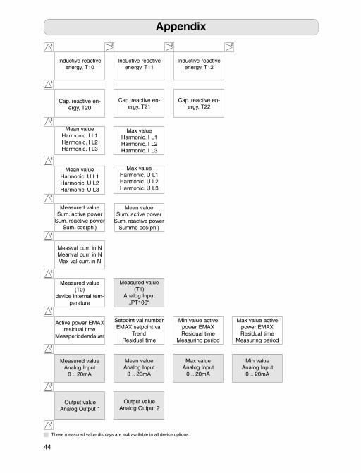
Measured value displays (factory default settings)
44
3
3
Cap. reactive en-ergy, T20
Cap. reactive en-ergy, T22
Cap. reactive en-ergy, T21
Inductive reactive energy, T10
Inductive reactive energy, T11
Inductive reactive energy, T12
Mean value Harmonic. I L1Harmonic. I L2Harmonic. I L3
Max value Harmonic. I L1Harmonic. I L2Harmonic. I L3
3
3
3
Measured value Sum. active power
Sum. reactive powerSum. cos(phi)
Mean valueSum. active power
Sum. reactive powerSumme cos(phi)
Measval curr. in NMeanval curr. in NMax val curr. in N
Mean value Harmonic. U L1Harmonic. U L2Harmonic. U L3
Max value Harmonic. U L1Harmonic. U L2Harmonic. U L3
Active power EMAX residual time
Messperiodendauer
Setpoint val numberEMAX setpoint val
TrendResidual time
Max value active power EMAXResidual time
Measuring period
Min value active power EMAXResidual time
Measuring period
3
3
3
Measured value (T0)
device internal tem-perature
Measured value (T1)
Analog Input„PT100“
Measured valueAnalog Input
0 .. 20mA
Mean valueAnalog Input
0 .. 20mA
Max valueAnalog Input
0 .. 20mA
Min valueAnalog Input
0 .. 20mA
3 2 22
Appendix
Output valueAnalog Output 1
Output valueAnalog Output 2
3
3
These measured value displays are not available in all device options.
45
3 2 22
Input 1digitalon/off
Input 2digital on/off
Input 6digital on/off
3
3
EMAX-Mean valueResidual time
Messperiodendauer
SolwertnummerTrendwertSollwert
Residual time
HöchstwertResidual time
Messperiodendauer
3
3
Appendix
Software ReleaseX.XXX
SeriennummerXXXXXXXX
WochentagJahr / MonatTag / Stunde
Minute / Sekunde
Output 1digitalon/off
Output 2digital on/off
Output 6digital on/off
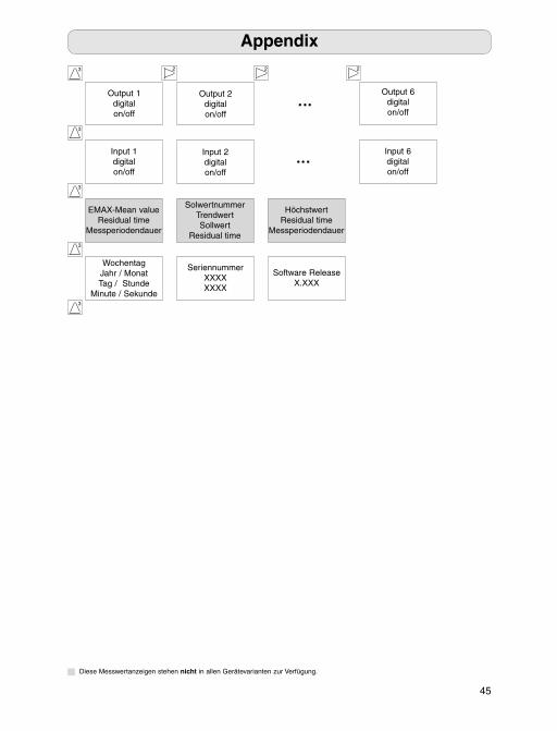
Diese Messwertanzeigen stehen nicht in allen Gerätevarianten zur Verfügung.
46
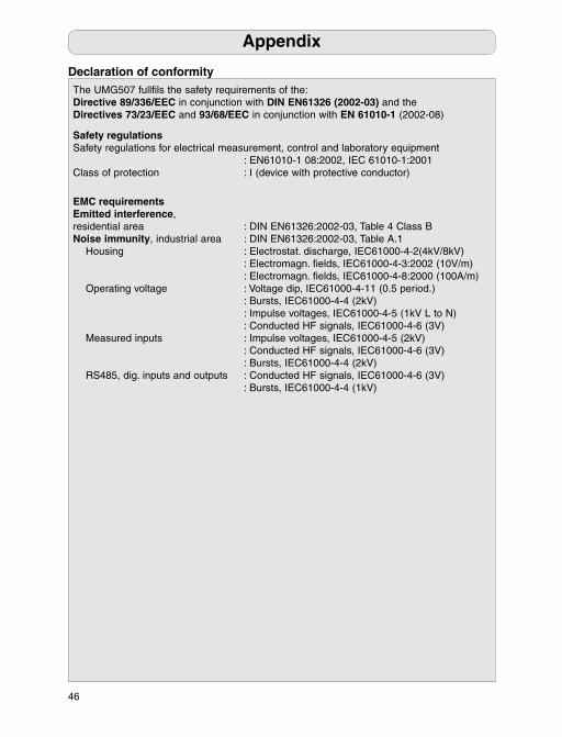
The UMG507 fullfi ls the safety requirements of the:Directive 89/336/EEC in conjunction with DIN EN61326 (2002-03) and theDirectives 73/23/EEC and 93/68/EEC in conjunction with EN 61010-1 (2002-08)
Safety regulationsSafety regulations for electrical measurement, control and laboratory equipment : EN61010-1 08:2002, IEC 61010-1:2001Class of protection : I (device with protective conductor)
EMC requirementsEmitted interference, residential area : DIN EN61326:2002-03, Table 4 Class BNoise immunity, industrial area : DIN EN61326:2002-03, Table A.1 Housing : Electrostat. discharge, IEC61000-4-2(4kV/8kV) : Electromagn. fi elds, IEC61000-4-3:2002 (10V/m) : Electromagn. fi elds, IEC61000-4-8:2000 (100A/m) Operating voltage : Voltage dip, IEC61000-4-11 (0.5 period.) : Bursts, IEC61000-4-4 (2kV) : Impulse voltages, IEC61000-4-5 (1kV L to N) : Conducted HF signals, IEC61000-4-6 (3V) Measured inputs : Impulse voltages, IEC61000-4-5 (2kV) : Conducted HF signals, IEC61000-4-6 (3V) : Bursts, IEC61000-4-4 (2kV) RS485, dig. inputs and outputs : Conducted HF signals, IEC61000-4-6 (3V) : Bursts, IEC61000-4-4 (1kV)
Appendix
Declaration of conformity
47
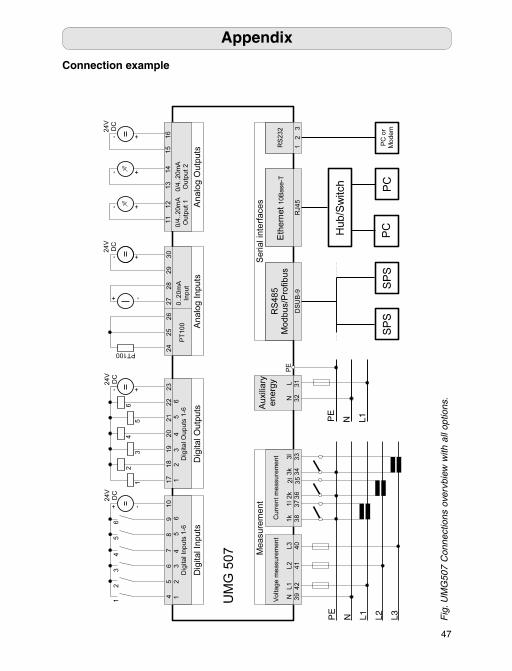
Fig
. UM
G50
7 C
onne
ctio
ns o
verv
biew
with
all
optio
ns.
Appendix
Connection example
: EN61010-1 0 : I (device with protective conductor)
E
: DIN EN61326:2002-03, Table 4 Class BN : Electrostat. d : Electromagn. fi : Electromagn. fi : Voltage dip, IEC61000-4-11 (0.5 period.) : Bursts, I : Impulse voltages, IEC61000-4-5 (1kV L to N) : Conducted HF signals, IEC61000-4-6 (3V) : Impulse voltages, IEC61000-4-5 (2kV) : Conducted HF signals, IEC61000-4-6 (3V) : Bursts, I : Bursts, I
48
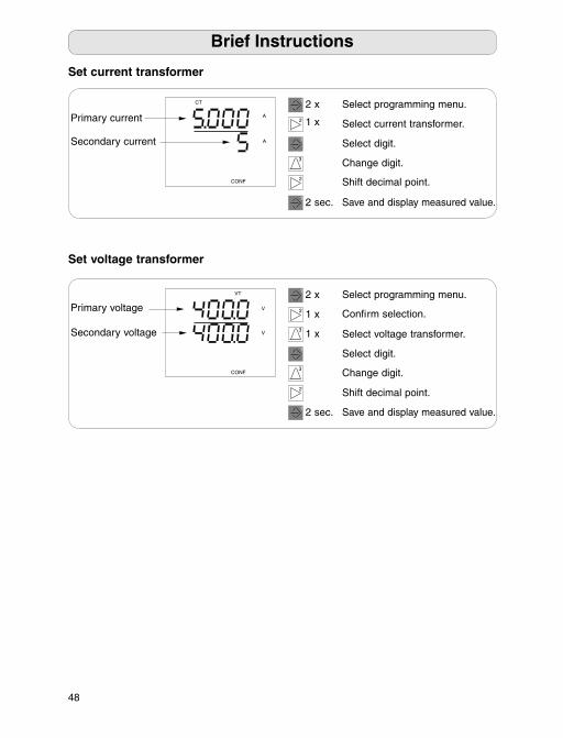
Secondary current
Secondary voltage
Set current transformer
Brief Instructions
CT
CONF
A
A
VT
CONF
V
V
Set voltage transformer
Primary current
Primary voltage
2
1
3
1
1
2
2 x
1 x
2 sec.
Select programming menu.
Select current transformer.
Select digit.
Change digit.
Shift decimal point.
Save and display measured value.
2 x
1 x
2 sec.
Select programming menu.
Select voltage transformer.
Select digit.
Change digit.
Shift decimal point.
Save and display measured value.
1
2
1
3
2
1
3 1 x
Confi rm selection.