Embed Size (px)
Citation preview

EN English UMI-0104-100714
UBS 1.04 Operating instructions
(R)
(B)
LN Ls1 2
UNIVERSAL RELAY SWITCH

II
Revision History
Rev. Doc.
Date Revisor Pag. Description
1 24/06/2014 RC 6,7,8, 12
Minor updates regarding text
10 Text “32 (0x1E)” changed in “32 (0x20)”
Text “33 (0x1F)” changed in “33 (0x21)”
Text “34 (0x1E)” changed in “34 (0x22)”
Text “35 (0x1F)” changed in “35 (0x23)”
Text “36 (0x1E)” changed in “36 (0x24)”
Text “37 (0x1F)” changed in “37 (0x25)”
11 Text “0 – TIMER ENABLED” changed in “0 – TIMER DISABLED”
Text “1 – TIMER DISABLED” changed in “1 – TIMER ENABLED”
12 Removed row “IGNORE” from the first table
2 10/07/2014 RC II,1,8,9,10,11,12
Minor updates regarding text
3 04/09/2014 RC 10 Changed range of values in “Setting ON_LEVEL and OFF_LEVEL”
10 Texts “255 – ON” changed in “255(0xFF) – ON”
14 Added “Disposing the devices”
8,15 Minor updates regarding text

1
Device description
Line Phase connection terminals
Null Neutral connection terminals
Relay Contact Latching Relay Contacts
Line signal This terminal gets a phase signal that drives the relay. The system recognises the status change of this connection (switch from 0 to phase voltage and vice versa)
Reset Pressing this button the system will restart
Push Button Service button: 1 or 3 clicks enters Learning Mode, with 6 clicks the system is reset to factory settings
Technical Specification
Power supply 230 VAC±10% 50/60 Hz
Maximum Load 2500 VA – 250 VAC - 10A resistive load in AC
300 VA – 30 VDC – 10A resistive load in DC
System temperature limitation 105 °C
Work temperature 0 – 40° C
Radio protocol Z-Wave 868,4 MHz
Range up to 60 m outdoors, up to 30 m indoors
Dimensions (HxWxD) 43x43x17 mm
Consumption <210 mW
Actuator element Latching relay
Conformity CE, RoHs
Push Button
Reset
LineNull RelayContact
Line signal
(R)
(B)
LN Ls1 2

2
Introduction
WiDom Universal Relay Switch is a Z-Wave certified “in wall device”.
The device is based on the use of a latching relay that is combined with an innovative design and effective
implementation to ensure extremely low energy consumption.
WiDom Universal Relay Switch is designed for being installed in junction boxes, flush mount boxes and near
lights. WiDom Universal Relay Switch is an ON\OFF device and can be used as both a local and remote
switch. It supports two wire connections, which allows it to be installed into any existing system without the
need to change the wiring.
At the same time, it is completely configurable so that it can adapt to the most varied needs while also being
ready to be used without needing additional configurations in order to operate.
Thanks to the framework developed by WiDom, the various types of “events” on the “External Switch” can be
recognised and associated to actions to be performed on the device, and\or on any associated devices and\or
on all devices on the network. The events that the system recognises are the number of “clicks” or hold on the
External Switch.
Although Z-Wave is quite new technology, it has already become recognizable and officially binding standard,
similarly to Wi-Fi. Many manufacturers in various industries offer solutions based on Z-Wave technology,
guaranteeing their compatibility. This means that the system is open and it may be extended in the future.
External Switch: Any switch, button or traditional wall control connected to the device in order to turn it
on or off.
Events: The actions performed on the external Switch: Clicks or Hold.
Click: If the external switch is a button (when pressed it returns to the start position by itself), a click
means pressing and then releasing it. If the external switch is a bistable one (after being pressed it does
not return to the original position), a single click means one single flip of the switch.
Hold: This applies only to buttons that are normally open and that are identified as such when the
pressure phase lasts at least 1,5 seconds.
Device in ON\OFF status refers to the fact that the latching relay contact is in the Open\Close position.

3
Installation
WARNING: WiDom Universal Relay Switch must be installed by a certified electrician in compliance with
the safety requirements set forth in national law regulations.
DANGER: WiDom Universal Relay Switch must be connected to 240VAC. Before performing any
installation operations, make sure the main switch on the meter is set to OFF.
DANGER: Any procedure that calls for the use of the (R) and (B) service buttons is related only to the
installation phase and is to be considered a service procedure that must be performed by qualified
personnel. This operation must be performed with all necessary precautions for operating in areas with a single
level of insulation.
WARNING: Do not connect loads that exceed the maximum load permitted by the relay contacts. In the
case of greater loads, WiDom Universal Relay Switch may be used to control an external relay or a
contactor. For non-resistive loads, the maximum load must be appropriately reduced.
WARNING: All connections must be performed according to the electrical diagrams provided
WiDom Universal Relay Switch Activation
1) Make sure the mains switch is set to the OFF position
2) Connect the device based on the diagrams provided
3) Close the electrical box that contains the device
4) Turn the system back on
5) Include the device in the Z-Wave network
TIP: The antenna must not be shortened, removed or modified. To ensure maximum
efficiency, it must be installed as shown. Metal equipment near the antenna can
negatively affect reception. Each WiDom device is a node in a mesh network. If there are
metal obstacles, the obstacle can often be overcome with a further triangulation node.
(R)
(B)
LN Ls1 2

4
Three-Wire connection
The device must be supplied by phase and neutral. The third control wire carries a phase signal on the Ls
terminal controlled by the external switch.
Diagram A Diagram B
N) Neutral; L) Phase; 1 and 2) Relay contacts; Ls) Control contact
N) Neutral; L) Phase; 1 and 2) Relay contacts; Ls) Control contact
*Maximum wire length<15m
INFO: The external switch can be either a bistable, a normally opened button or any sequence of SPDT
- DPDT (Fig.AB.1) or buttons (Fig.AB.2).
Fig.AB.1 Fig.AB.2
INFO: If using a secondary load supply system, it must be connected as in diagram B. The supply voltage
can be either AC or DC within the limits permitted by the relay contact, up to 250 V in AC and up to 30 V
in DC.
WARNING: The line connected to the relay contacts must be suitably protected from short circuits and
overloads connected to a possible failure of the connected load
L
N
(R)
(B)
LN Ls1 2
Bistable switch Normally Opened
monostable switch
SecondaryPower Supply
System
L
N
(R)
(B)
LN Ls1 2
Bistable switch Normally Opened
monostable switch
L LsLs

5
Two wire connection - AC Sensing
With this type of connection, the momentary interruption of the phase is interpreted by the system as a load
switching command. This configuration is suitable for controlling existing lighting system.
Diagram C Diagram D
N) Neutral; L) Phase; 1 and 2) Relay contacts; Ls) Control contact
N) Neutral; L) Phase; 1 and 2) Relay contacts; Ls) Control contact
*Maximum wire length<15m
INFO: The external switch can be a normally closed button as well as any series, as shown in figure
CD.1.
Fig.CD.1 Fig.CD.2
TIP: In this mode, the device can be installed near the light to be controlled and the existing switch is
replaced with a normally closed button. For a light controlled from several points, all of the switches
should be replaced with normally closed buttons. Please note that in this case another connection that may
work is shown in figure CD.2 where the necessary modified connection for just one of the switches is
represented.
TIP: In order to control a neon tube with a traditional ballast and a starter and in general with non-pure
resistive loads or with long wire connections a WiDom Switch Helper should be connected in parallel to
the load as shown in diagram C.
INFO: If using a secondary load supply system, it must be connected as in diagram D. The supply
voltage can be either AC or DC within the limits permitted by the relay contact, up to 250 V in AC and
up to 30 V in DC.
WARNING: The line connected to the relay contacts must be suitably protected from short circuits and
overloads connected to a possible failure of the connected load.
L
N
(R)
(B)
LN Ls1 2
Optional: WiDomSwitch Helper
Normally Closedmonostable switch
SecondaryPower Supply
System
L
N
(R)
(B)
LN Ls1 2
Normally Closedmonostable switch
LsLL

6
Reset to the factory settings
The device can be reset to the original factory settings using one of the following methods: Method 1: Remove the device from the Z-Wave network
Method 2: Six consecutive clicks on button (B)
Method 3: Set parameter 61 to value 0 - FACTORY RESET (see paragraph 0).
INFO: If the reset is performed while the device is still part of a network, it notifies the other devices that
it has been removed (Device Reset Locally Notification). If WiDom Universal Relay Switch receives a
removal notification from another device, it will delete the removed device from its own associations.
Including the device into an existing Z-Wave network
WiDom Universal Relay Switch can be included and operated in any Z-Wave network with other Z-Wave
certified devices from any other manufacturers. As constantly powered node WiDom Universal Relay Switch
will act as repeater regardless of the vendor in order to increase reliability of the network.
The device supports both the Network Wide Inclusion mechanism (which offers the ability to be included in a
network even if the device is not in the direct range of the controller) and Normal Inclusion.
By default, if the device is not included in any network, as soon as it is powered the Network Wide Inclusion
procedure starts and lasts for about 1 minute. The procedure can be reactivated at the next device restart or
by pressing the (R) button.
If the used controller does not support the Network Wide Inclusion functionality, the device may be included in
the network through Normal Inclusion by pressing the (B) button once or three times or alternatively by pressing
the external switch once.
INFO: During the inclusion procedure activated by a single click on the external switch, the system also
automatically determines the switch type (See parameter No. 62).
Excluding the device from a Z-Wave network
Only a controller can remove a device from the network. WiDom Universal Relay Switch is compatible with all
Z-Wave certified controllers. After the exclusion function has been activated from the controller, the device can
be removed, putting it in Learning Mode by pressing the (B) button once or three times or more conveniently
by using the external switch after having enabled the learning mode activation from external switch (see
parameter N°65).
Request network update
If there is a SUC (Static Update Controller) or SIS (SUC ID Server) in the network, a network update can be
requested by pressing the external switch four times.
Associations
WiDom Universal Relay Switch can control other devices like other relays or dimmers. WiDom Universal Relay
Switch supports 5 association groups:
Group 1: devices that will be notified of changes in its status
Group 2: devices that will be controlled by a single click on the external switch
Group 3: devices that will be controlled by a double click on the external switch
Group 4: devices that will be controlled by a triple click on the external switch
Group 5: devices that will be controlled by hold on the external switch
TIP: WiDom Universal Relay Switch can control up to 16 devices for each group. To avoid network
delays, we recommend limiting the amount of associated devices to no more than 5 per group.

7
Controlling the device with an external switch
With WiDom devices, the normal switches/buttons found in a traditional electrical system can become
intelligent control systems.
WiDom Framework recognises the number of clicks or hold event on the external switch and can be configured
to perform different actions based on the identified event.
Controlling the device via the Z-Wave network
All Z-Wave controllers can control the device using the Basic Set command.
The behaviour of the device based on its status and on the commands received from the network can also be
configured.
Alarms management
WiDom Universal Relay Switch can also be configured to react to alarm notifications from sensors on the
network. WiDom Universal Relay Switch recognises and complies with Notification V3 Report frame alarm
notifications.
INFO: By default, WiDom Universal Relay Switch reacts to smoke, heat, water and home security alarms
generated by others Z-Wave sensors in the system. The reaction type: ON, OFF or FLASHING can be
configured as needed.
Switch ALL ON\OFF
By default, WiDom Universal Relay Switch accepts Switch All ON\OFF commands.
Timer option
WiDom Universal Relay Switch has a built-in configurable timer for programmed switch-off.
Troubleshooting
By pressing the (B) and (R) buttons at the same time and then releasing (R), the system starts a check
procedure that can produce one of the following results:
1. If the device is included in a network, it switches from ON to OFF repeatedly with equal ON and OFF
times of 2 seconds each.
2. If the device is not included in a network, it switches from ON to OFF repeatedly with an ON time of 2
seconds and an OFF time of 6 seconds.
INFO: The procedure described lasts until the (R) button is pressed again.
Configurations
Controlling the device by external switch
Clicks on the external switch turn the connected load on or off depending on the initial status, on the number
of clicks and on the device configuration. The actions that will be performed on the associated devices and on
all other devices on the network can also be configured.
INFO: As soon as the click recognition process has completed, the device will be set to the desired
status, any switch all on\off actions will be performed and the associated devices will be controlled.

8
Device status
The final device status will be determined by the initial status, number of clicks or hold. The following
configurations can be used to configure parameters 1 through 4.
Value Initial status Final status
1 – TOGGLE ON OFF
OFF ON
2 – ON ON If the initial status is OFF, the system will switch ON; otherwise, it
maintains its status (ON). OFF
3 – OFF ON If the initial status is ON, the system will switch OFF; otherwise, it
maintains its status (OFF). OFF
4 – IGNORE ON The device maintains its initial status and if the programmed
switch-off timer is active, it is restarted. OFF
Parameter No. 1: Device status when the external switch receives 1 click (1 byte). Default value: 1 – TOGGLE
Parameter No. 2: Device status when the external switch receives 2 clicks (1 byte). Default value: 1 – TOGGLE
Parameter No. 3: Device status when the external switch receives 3 clicks (1 byte). Default value: 1 – TOGGLE
Parameter No. 4: Device status when the external switch is held down (1 byte) - This parameter only takes effect if a normally open button is connected.
Default value: 1 – TOGGLE
WARNING: Careless usage of the configuration parameters can create inconsistencies.
Controlling the associated devices
The actions performed on associated devices in terms of Basic Set will be determined by the initial status,
number of clicks or hold. The following configurations can be used to configure parameters 5 through 8.
Configuration Initial device status
Action performed on the associated device
1 – TOGGLE ON Basic Set OFF_LEVEL
OFF Basic Set ON_LEVEL
2 – IGNORE IF ON ON No action
OFF Basic Set ON_LEVEL
3 – IGNORE IF OFF ON Basic Set OFF_LEVEL
OFF No action
4 – TOGGLE ASSOCIATED
ON The status of each associated device is requested with the Basic Get command. If it is OFF, the Basic Set ON command is sent, otherwise the Basic Set OFF command is sent. OFF
5 – SET AS INITIAL STATUS VALUE
ON Basic Set ON_LEVEL
OFF Basic Set OFF_LEVEL
6 – IGNORE ON
No action OFF
TIP: TOGGLE ASSOCIATED: This configuration is useful for configuring the device as a remote switch. We recommend this configuration for controlling a single remote device. When using this option, in order
to avoid any inconsistent result, we recommend keeping the Switch All actions disabled.

9
Parameter No. 5: Action on the associated devices when the external switch receives 1 click (1 byte). Default value: 1 – TOGGLE
Parameter No. 6: Action on the associated devices when the external switch receives 2 clicks (1 byte).
Default value: 1 – TOGGLE
Parameter No. 7: Action on the associated devices when the external switch receives 3 clicks (1 byte).
Default value: 6 – IGNORE
Parameter No. 8: Action on the associated devices when the external switch is held down (1 byte). Default value: 1 – TOGGLE
Switch ALL functionality
The actions performed on all network devices in terms of Switch ALL will be determined by the initial status,
number of clicks or hold. If there are associated devices and there are control actions set for these devices,
the Switch ALL actions are performed first.
The following configurations can be used to configure parameters 9 through 12.
Value Initial device status
Action performed on all devices in the network
1 – TOGGLE ON SWITCH ALL OFF
OFF SWITCH ALL ON
2 – IGNORE IF ON ON No action
OFF SWITCH ALL ON
3 – IGNORE IF OFF ON SWITCH ALL OFF
OFF No action
4 – SET AS INITIAL STATUS VALUE
ON SWITCH ALL ON
OFF SWITCH ALL OFF
5 – IGNORE ON
No action OFF
Parameter No. 9: Action performed on all network devices when the external switch receives 1 click (1 byte). Default value: 5 – IGNORE
Parameter No. 10 (0xA): Action performed on all network devices when the external switch receives 2 clicks (1 byte). Default value: 5 – IGNORE
Parameter No. 11 (0xB): Action performed on all network devices when the external switch receives 3 clicks (1 byte). Default value: 5 – IGNORE
Parameter No. 12 (0xC): Action performed on all network devices when the external switch is held down (1 byte). Default value: 5 – IGNORE

10
Controlling the device by Z-Wave Network
The device final status reached by the device when it receives a Basic Set command from the Z-Wave network.
Parameter No. 20 (0x14): Device status upon receipt of a Basic Set (1 byte)
Value Command received
Final status
1 – HOW RECEIVED
(Default value)
ON ON
OFF OFF
2 – IGNORE IF ON ON Maintains the initial status
OFF OFF
3 – IGNORE IF OFF ON ON
OFF Maintains the initial status
4 - IGNORE ON Maintains the initial status and, if the programmed switch-off timer
is active, it is restarted. OFF
Setting ON_LEVEL and OFF_LEVEL
Defines the values associated to the ON_LEVEL and OFF_LEVEL parameters used in the Basic Set
commands. The following values can be used to configure parameters 30 through 37.
From: 1 to 99 for dimming purpose – 0 (OFF) and 255(0xFF) (ON) for switching ON\OFF
Parameter No. 30 (0x1E): ON_LEVEL value used for devices belonging to Group 2 (1 Click association group) (1 byte).
Default value 255(0xFF) – ON
Parameter No. 31 (0x1F): OFF_LEVEL value used for devices belonging to Group 2 (1 Click association group) (1 byte).
Default value 0 – OFF
Parameter No. 32 (0x20): ON_LEVEL value used for devices belonging to Group 3 (2 Click association group) (1 byte).
Default value 255(0xFF) – ON
Parameter No. 33 (0x21): OFF_LEVEL value used for devices belonging to Group 3 (2 Click association group) (1 byte).
Default value 0 – OFF
Parameter No. 34 (0x22): ON_LEVEL value used for devices belonging to Group 4 (3 Click association group) (1 byte).
Default value 255(0xFF) – ON
Parameter No. 35 (0x23): OFF_LEVEL value used for devices belonging to Group 4 (3 Click association group) (1 byte).
Default value 0 – OFF
Parameter No. 36 (0x24): ON_LEVEL value used for devices belonging to Group 5 (Hold association group) (1 byte).
Default value 255(0xFF) – ON
Parameter No. 37 (0x25): OFF_LEVEL value used for devices belonging to Group 5 (Hold association group) (1 byte).
Default value 0 – OFF

11
Timer Option
Enabling the timer for relay switch-off
The switch-off timer can be associated with any click or hold event. When the timer is enabled for the specific
event that generated the ON status, the device will go into the OFF status after the period of time defined in
parameter No. 45. The following configuration values can be used for parameters 40 through 44.
0 – TIMER DISABLED
1 – TIMER ENABLED
Parameter No. 40 (0x28): Timer associated with the 1 click event on the external switch (1 byte) - Enables the switch-off timer if the device switches to ON following a single click on the external switch. Default value: 0 – TIMER DISABLED
Parameter No. 41 (0x29): Timer associated with the 2 click event on the external switch (1 byte) - Enables the switch-off timer if the device switches to ON following a double click on the external switch. Default value: 0 – TIMER DISABLED
Parameter No. 42 (0x2A): Timer associated with the 3 click event on the external switch (1 byte) - Enables the switch-off timer if the device switches to ON following a triple click on the external switch. Default value: 0 – TIMER DISABLED
Parameter No. 43 (0x2B): Timer associated with the hold event on the external switch (1 byte) - Enables the switch-off timer if the device switches to ON following hold on the external switch. Default value: 0 – TIMER DISABLED
Parameter No. 44 (0x2C): Timer associated with the reception of a Basic Set command (1 byte) - Enables the switch-off timer if the device switches to ON following reception of a single click Basic Set command.
Default value: 0 – TIMER DISABLED
Parameter No. 45 (0x2D): Switch-off timer (2 bytes) Defines the amount of time before the switch-off timer takes place Time in seconds (1 – 3600);
Default value 600 (0x258), 10 minutes.
Parameter No. 46 (0x2E): Switch-off timer validity (1 byte) - Defines the system behaviour if an event requests a status change for the device and the timer for the programmed switch-off timer was started by a previous event.
Configuration Device reaction
0 - CANCEL The switch-off timer is cancelled and the device maintains the last status reached. If the new status is ON and the event that generated it is associated with the timer, it is restarted.
1 - MAINTAIN
Default value The switch-off timer is maintained
Manage Alarms
WiDom devices can react to alarms received. The system recognises alarm messages (version 3 of Alarm
Command Class). By default, all alarms are ignored except for those defined in the following table:
Alarm Alarm or Notification Type Event
Event Parameters
Smoke Alarm, CO, CO2 0x01 – 0x02 – 0x03 ANY ANY
Heat Alarm 0x04 ANY ANY
Water Alarm 0x05 ANY ANY
Home Security 0x07 ANY ANY
12
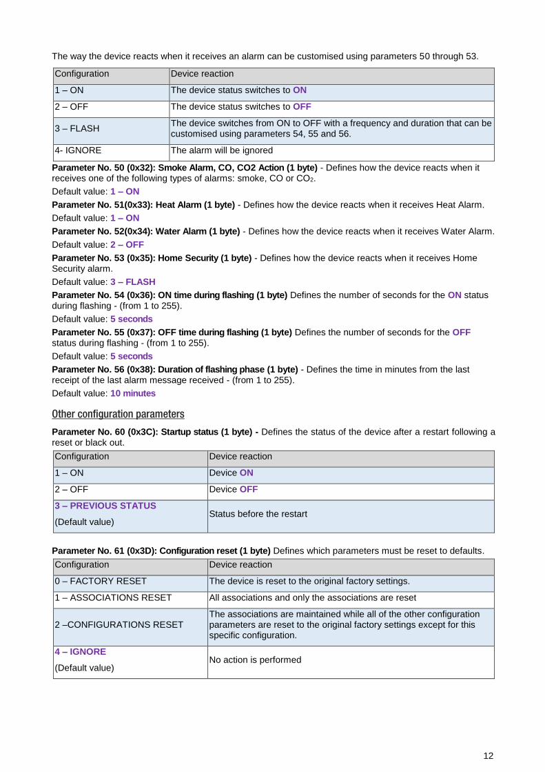
The way the device reacts when it receives an alarm can be customised using parameters 50 through 53.
Configuration Device reaction
1 – ON The device status switches to ON
2 – OFF The device status switches to OFF
3 – FLASH The device switches from ON to OFF with a frequency and duration that can be customised using parameters 54, 55 and 56.
4- IGNORE The alarm will be ignored
Parameter No. 50 (0x32): Smoke Alarm, CO, CO2 Action (1 byte) - Defines how the device reacts when it receives one of the following types of alarms: smoke, CO or CO2.
Default value: 1 – ON
Parameter No. 51(0x33): Heat Alarm (1 byte) - Defines how the device reacts when it receives Heat Alarm.
Default value: 1 – ON
Parameter No. 52(0x34): Water Alarm (1 byte) - Defines how the device reacts when it receives Water Alarm.
Default value: 2 – OFF
Parameter No. 53 (0x35): Home Security (1 byte) - Defines how the device reacts when it receives Home Security alarm.
Default value: 3 – FLASH
Parameter No. 54 (0x36): ON time during flashing (1 byte) Defines the number of seconds for the ON status during flashing - (from 1 to 255).
Default value: 5 seconds
Parameter No. 55 (0x37): OFF time during flashing (1 byte) Defines the number of seconds for the OFF status during flashing - (from 1 to 255).
Default value: 5 seconds
Parameter No. 56 (0x38): Duration of flashing phase (1 byte) - Defines the time in minutes from the last receipt of the last alarm message received - (from 1 to 255).
Default value: 10 minutes
Other configuration parameters
Parameter No. 60 (0x3C): Startup status (1 byte) - Defines the status of the device after a restart following a reset or black out.
Configuration Device reaction
1 – ON Device ON
2 – OFF Device OFF
3 – PREVIOUS STATUS
(Default value) Status before the restart
Parameter No. 61 (0x3D): Configuration reset (1 byte) Defines which parameters must be reset to defaults.
Configuration Device reaction
0 – FACTORY RESET The device is reset to the original factory settings.
1 – ASSOCIATIONS RESET All associations and only the associations are reset
2 –CONFIGURATIONS RESET The associations are maintained while all of the other configuration parameters are reset to the original factory settings except for this specific configuration.
4 – IGNORE
(Default value) No action is performed

13
Parameter No. 62 (0x3E): Type of external switch (1 byte) - Defines the type of external switch connected to the device.
Configuration Device reaction
0 – IGNORE The actions on the external switch are ignored. In this mode, the device can only be controlled via the network.
1 – BUTTON The external switch is a normally open button
2 – BISTABLE SWITCH The external switch is a traditional switch
3 – AC SENSING The external switch is a normally closed button connected as shown in diagrams C and D
4 – AUTOMATIC RECOGNITION
(Default value)
After the first single click on the external switch, the system automatically determines the type of external switch used and accordingly sets the parameter with the new value.
Parameter No. 63 (0x3F): Sensitivity (1 byte) - Sets the level of sensitivity associated with the AC SENSING configuration.The value can be set between 0 (High sensitivity) and 255 (Low sensitivity).
Default Value: 9
Parameter No. 64 (0x41): Load protection (2 bytes) Defines the minimum amount of time in which the switch cannot be flipped twice in succession. Time in seconds (1 – 3600).
Default value: 0
INFO: Some types of loads require a rest period between switch-off and subsequent switch-on. This
parameter is for setting this time. If this parameter is set and the load is off, when the device receives a
switch-on command, it will be performed as soon as the protection time has been reached.
Parameter No. 65 (0x40): Learn Mode (1 byte) - This defines the sequence of clicks on the external switch to associate to Learning Mode.
Configuration Device reaction
0 – DISABLED
(Default value) Learning mode cannot be activated from the external switch
1 – 1 CLICK Learning mode is activated by 1 click on the external switch
2 – 2 CLICKS Learning mode is activated by 2 clicks on the external switch
3 – 3 CLICKS Learning mode is activated by 3 clicks on the external switch
INFO: When Learning mode is associated to a click event any configurations related to the associated devices and Switch All commands related to the same event are ignored. After the learning mode has
been associated to a click event this configuration is honoured for a single event. After that event the Learning mode parameter will be reset to the default value (0 – DISABLED).

14
Disposing the devices
This product bears the selective sorting symbol for waste electrical and electronic equipment
(WEEE).
This means that this product must be handled pursuant to European Directive 2002/96/EC in
order to be recycled or dismantled to minimize its impact on the environment.
For further information, please contact your local or regional authorities.
Electronic products not included in the selective sorting process are potentially dangerous for
the environment and human health due to the presence of hazardous substances.
Compliance with directives
WiDom devices are built in compliance with directives LVD 2006/95/EC, EMC 2004/108/CE and R&TTE
Widom shall not be held responsible for any damage caused by these devices if they are used in a manner
that is not compliant with the instructions in this manual. WiDom reserves the right to make any changes to
the product that it considers necessary or useful without jeopardising its primary features.
Warranty
This warranty is provided by WiDom srl (hereinafter “WiDom”) based in Quartu S.Elena 09045 (CA), Italy (VAT number
03452490927).
WiDom warrants to the original purchaser (hereinafter “Customer”) that the device sold under this agreement (hereinafter
“Device”) is free from defects in parts and workmanship under normal use for 12 months from date of purchase (“Warranty
Period”).
The original purchase invoice or sales receipt, showing the date of purchase is the proof of date of purchase by the Customer.
If a Device, sold by WiDom to the Customer, has manufacturing defects or in any case of alleged lack of conformity, the
Customer shall send within thirty (30) days from the day in which he discovers such defects, a claim form by using our web
site: (www.widom.it) informing WiDom on the full name of the Customer, the nature of the defects and the date in which the
Devices has been purchased.
Warranty Claims received after the expiration of the Warranty Period shall not be considered valid.
Once WiDom, receives the Warranty Claim, it shall inform the Customer by e-mail or letter, if the Warranty is applicable and
the address where the Device shall be sent in order to verify the defects (if any). Customer must prepay shipping and
transportation charges as indicated by WiDom. The Device shall be sent by the Customer to WiDom at its own costs and
expenses, by express courier or hand delivered, and with the original packaging, the supplied accessories (if any) and
documents proving date of purchase. WiDom shall then inform the Customer about the defects and on its repair or replacement
(where applicable). Should WiDom not evidence defects on the Device, the Device shall be returned to the Customer.
Should WiDom notices the defects, and this warranty is applicable, it will remove, at its sole discretion, any defect, free of
charge, by repairing any defective components of the Device with new or regenerated components or by replacing the Device.
The Warranty Period of the replaced or repaired Device shall not be extended.
WiDom will ship the repaired or a replaced Device to Customer freight prepaid.
WiDom will not be liable for damages to property caused by faulty device. WiDom will not be liable for indirect, incidental,
special, consequential or punitive damages, or for any damage, including, inter alia, loss of profits, savings, data, loss of
benefits, claims by third parties and any property damage or personal injuries arising from or related to the use of the Device.
If the Device cannot be replaced with another of the same type (e.g. the Device is no longer in production or no longer available
for selling in the Customer’s country), it may be replaced with a different one having similar technical specifications to the
faulty one. Such replacement shall be considered as a total fulfilment of WiDom’s obligations.
Warranty exclusion
- defects caused by normal wear of parts or especially subject to wear, such as parts that require periodic replacement during
the normal operation of the system (eg. Batteries);

15
- splits, cracks, scratches, dents, scratched or discolored surfaces and parts, breakage of plastic parts and in general of any
other cosmetic damage;
- damages resulting from use of the system other than that provided, including but not limited to the failure to follow
instructions contained in the operating manual;
- damages caused by accident, abuse, misuse, dirt, viruses, liquid contact, fire, earthquake, improper or inadequate
maintenance or calibration, negligence or other external causes;
- environmental damage and / or defects caused by smoke, dust, dirt, soot, or other external influences;
- damages caused by modifications and alterations in the functionality or features without the written permission of WiDom;
- damages resulting from transportation or inadequate packaging when returning the product to a WiDom or to an authorize
service center;
- defects caused by force majeure events such as lightning, floods, fires, incorrect voltage, improper ventilation;
- damages caused by malfunctioning software, computer virus attack, or by failure to update the software as recommended
by WiDom;
- damages resulting from surges in the power and/or telecommunication network, improper connection to the grid in a manner
inconsistent with the operating manual, or from connecting other devices not recommended by WiDom;
- damages caused by operating or storing the device in extremely adverse conditions, i.e. high humidity, dust, too low (freezing)
or too high ambient temperature;
- products whose serial number has been removed, damaged or rendered illegible;
- expiration of the Warranty Period.
If a defect is not covered by the Warranty, WiDom will inform the Customer about the extra expenses for the repair or
replacement.
This warranty may be subject to changes. Please check at: www.widom.it the newest warranty claim procedure.
This guarantee shall not exclude, limit or suspend the Customer rights when the provided product is inconsistent with the
purchase agreement.
© All rights reserved. WiDom is a trademark of WiDom srl. All other brand names, product names, or trademarks belong to
their respective owners. WiDom reserves the right to change product features and specifications at any time without notice,
and is not responsible for typographical or graphical errors that may appear in this document.
Please check at: www.widom.it the newest version of this document.
Printed in Italy on low-impact recyclable paper.