Embed Size (px)
Citation preview

Universal Transformerfor Panel MountingOMNI-TA
● Compact universal signal evaluation device for control panel installation
● Signal converter function● Evaluation of current, voltage or
frequency signals● Analog output ● Two limit switches● Settings via magnetic pin on the front● Clear, easily legible, illuminated LCD display● Modifiable units in the display● IP 67 of the front
Characteristics
The OMNI-TA sensor electronics allows the measurement and eva-luation of:
● 0..20 mA or 4..20 mA current signals● 0..10 V or 2..10 V voltage signals ● 0..10 kHz frequencies (max. adjustable value 9999 Hz)
It is designated for control panel installation.
It includes a microcontroller which displays the sensor signal, moni-tors two adjustable limit values and operates an analogue output.
A display value can be assigned to bottom and top of range of theused input. The physical unit of the displayed value can be choo-sen out of a list (e.g. l/min, for available units see Technicaldata/Measured value representation).
Two limit values can be set at the device. They can be configuredas minimum or maximum monitoring. If the limit values are excee-ded, this is signalled by the blinking of a red LED with simultaneousclear text in the LCD display, as well as by the two switching out-puts in push-pull design.
Additionally the measurement is output as an analog signal.The electronics is available in two versions:Current output: 0..20 mA or 4..20 mA (selectable at the device)Voltage output: 0..10 V or 2..10 V (selectable at the device)
Thus the OMNI-TA device may be used as a signal transducer:current → voltagevoltage → currentfrequency → voltagefrequency → current
Customized software (e.g. counting function, other inputs or out-puts) is available on request.
Technical data
Metering ranges of the input values
Current: 0..20 mA / 4..20 mAVoltage: 0..10 V / 2..10 VFrequency: 0..9999 Hz
Others available on requestThresholds for frequency measu-rement
High-level > 25 % supplyLow-level < 15 % supplyOthers available on request
Resolution Analogue: 5 µA bzw. 2.5 mVFrequency: 0.5 Hz
Accuracy ±1%
Measured valuerepresentation
Positive values 4 digitsNegative values 3 digitsFreely applied decimal point
Available standard units:Relative:Flow rate:Pressure:Temperature:Level/Length:
%l/min, m³/h, l/hbar, psi°C, °Fcm
Others available on request
Operatingtemperature
0..+70 °C
Storage temp. -20..+80 °CMaterials Housing Stainless steel
1.4305Installation kit CW614N
nickelledFront Mineral glassSealings FKM
Supplyvoltage
18..30 V DC
Sensorsupply
corresponds to supply voltage -1.4 V
Currentconsumption
approx. 30 mA (plus output current and sensor supply current)
Analog output Current output version (OMNI-TA-IS):0..20 mA or 4..20 mA (selectable at device)load 500 Ohm max.
Voltage output version (OMNI-TA-US):0..10 V or 2..10 V (selectable at device)load 1 kOhm min.
Switching outputs Two transistor outputs push-pull(short circuit and reverse polarity proof)Iout = 100 mA max. per output
Connection Supply and signal outputs:Circular connector M12x1, 5-pinSensor connection: Screw terminals
Mounting hole Ø 45 mm, wall thickness max. 3 mmLCD display Graphic LCD display (32x16 pixel)
Background lightingIngress protection IP 67 (front)Weight approx. 0.25 kgConformity CE
pi-ho_umf-omni-ta_e V1.06-01
1

Wiring
Signal inputs
Assignment of screw terminals:
A +V Sensor supply voltage corre-sponds to supply voltage at cir-cular connector minus 1.4 V(internally connected to B: +V)
20 mA in Signal input 0..20 / 4..20 mA
0 V 0V / GND (connected to pin 3 ofcircular connector)
n.c. not connected
B +V Sensor supply voltage corre-sponds to supply voltage at cir-cular connector minus 1.4 V(internally connected to A: +V)
10 V in Signal input 0..10 / 2..10 V
0 V 0V / GND (connected to pin 3 ofcircular connector)
Freq. in Frequency input
Supply and signal outputs
Circular connector M12x1
Prior to electrical installation, it must be ensured that the supply vol-tage corresponds to the data sheet.The use of shielded cabling is recommended.
Dimensions
Handling and operation
Installation
Installation kit
Mounted device
The assembly in the control panel takes place using an installationkit (included in the scope of supply). A mounting hole (Ø 45 mm) inthe control panel is required. The front ring is fit through the holefrom the outside and secured from the inside by a nut (size 46).Then the OMNI-TA device is inserted in the ring from the inside andfixed with a threaded pin mounted on the side. The sealing bet-ween the front ring and control panel and the sealing between thefront ring and OMNI-TA device are provided by O-rings.
Operation and programming
Set to 1 = continueSet to 2 = modify
With the supplied magnet two switching areas on the glass front can be operated which are marked as 1 and 2 and the indication PROG. Operation is by dialogue with the display messages, which makes its use very simple.
2 pi-ho_umf-omni-ta_e V1.06-01
Z Z
1
2
3
4
5
brown
white
blue
black
grey
18..30 V DC
analog output
0 V
switching signal 1
switching signal 2
PNP NPNConnection example:
1
43
25
Z = Load
The following actions are possible:
Display of the parameters, using position 1
Starting from the normal display (currently measured value with unit), if 1 is repeatedly selected, then the display shows the followi-ng information in this order:
Switching value S1 Limit value 1 in the selected unit
Switching characteristic S1 Min = Minimum controlMax = Maximum control
Hyst 1 Hysteresis value of S1 in the selec-ted unit
Switching value S2 Limit value 2
Switching characteristic S2 Min / Max
Hyst 2 Hysteresis value of S2
Code 000
After entering code 111, further parameters can be defined:
Input Input signal, defines the signal input to be used:
0-20 mA4-20 mA0-10 V2-10 VFreq.
20 mA in20 mA in10 V in10 V inFrequency input
GateTim(only if Freq. is selected)
Gate time during which the input pul-ses are counted. The gate time de-termines on one hand the response time of the measurement and on theother hand the resolution of the fre-quency signal:0.25s (resolution 4 Hz)0.50s ( resolution 2 Hz)1.00s ( resolution 1 Hz) 2.00s ( resolution 0,5 Hz)
fmax(only if Freq. is selected)
Frequency, which corresponds to 100% of the measurement range, adjustable up to a maximum value of9999 Hz.Bottom of range is always 0 Hz
Filter Settling time of display and analog output:Off / 0,2s / 0,5s / 1s / 2s / 4s / 8s / 16s / 32sto smooth the reading in case of fluctuating input signals
Units Selection of the physical unit of the display (for available units see Tech-nical data/Measured value represen-tation)
DP Selection of number of decimal pla-ces of display reading:9999. (no decimal places)999.9 (one decimal place)99.99 (two decimal places)9.999 (three decimal places)
Scl Lo Lower scaling value:Display reading at bottom of range with previously selected number of decimal places
Scl Hi Upper scaling valuet:Display reading at top of range
Output for version with current output:0-20 mA / 4-20 mAfor version with voltage output:0-10 V / 2-10 V
Edit, using position 2
If the currently visible parameter is to be modified:● Set the magnet to position 2, so that a flashing cursor appears
which displays the position which can be modified.● With repeated actuation of position 2, values are increased; by
with actuation of position 1, the cursor moves to the next digit
● Exit the parameter by actuating position 1 (until the cursor lea-ves the row); this accepts the modification.
If there is no activity within 30 seconds, the device returns to thenormal display range without accepting the modification.
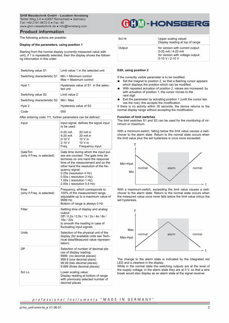
Function of limit switchesThe limit switches S1 and S2 can be used for the monitoring of mi-nimum or maximum.
With a minimum-switch, falling below the limit value causes a swit-chover to the alarm state. Return to the normal state occurs whenthe limit value plus the set hysteresis is once more exceeded.
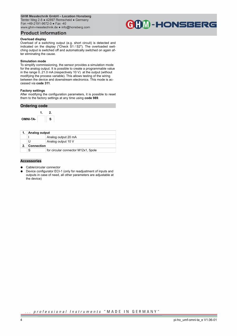
With a maximum-switch, exceeding the limit value causes a swit-chover to the alarm state. Return to the normal state occurs whenthe measured value once more falls below the limit value minus theset hysteresis.
The change to the alarm state is indicated by the integrated redLED and a cleartext in the display.While in the normal state the switching outputs are at the level ofthe supply voltage; in the alarm state they are at 0 V, so that a wirebreak would also display as an alarm state at the signal receiver.
pi-ho_umf-omni-ta_e V1.06-01
3
Min
Min+Hyst
t
T
Max-Hyst
t
T
Max
Overload displayOverload of a switching output (e.g. short circuit) is detected andindicated on the display ("Check S1 / S2"). The overloaded swit-ching output is switched off and automatically switched on again af-ter eliminating the cause.
Simulation modeTo simplify commissioning, the sensor provides a simulation mode for the analog output. It is possible to create a programmable value in the range 0..21.0 mA (respectively 10 V) at the output (without modifying the process variable). This allows testing of the wiring between the device and downstream electronics. This mode is ac-cessed via code 311.
Factory settingsAfter modifying the configuration parameters, it is possible to resetthem to the factory settings at any time using code 989.
Ordering code
1. 2.
OMNI-TA- S
1. Analog outputI Analog output 20 mAU Analog output 10 V
2. ConnectionS for circular connector M12x1, 5pole
Accessories
● Cable/circular connector● Device configurator ECI-1 (only for readjustment of inputs and
outputs in case of need, all other parameters are adjustable at the device)
4 pi-ho_umf-omni-ta_e V1.06-01