Embed Size (px)
Citation preview
UNIVERSIDAD POLITÉCNICA DE MADRID ESCUELA TÉCNICA SUPERIOR DE INGENIEROS DE TELECOMUNICACIÓN
NEW ADVANCES ON MULTI-FREQUENCY AND MULTI-BEAM REFLECTARRAYS
WITH APPLICATION TO SATELLITE ANTENNAS IN KA-BAND
TESIS DOCTORAL
Eduardo María Martínez de Rioja del Nido
Ingeniero de Telecomunicación
Madrid, 2018


DEPARTAMENTO DE SEÑALES, SISTEMAS Y RADIOCOMUNICACIONES
ESCUELA TÉCNICA SUPERIOR
DE INGENIEROS DE TELECOMUNICACIÓN
NEW ADVANCES ON MULTI-FREQUENCY AND MULTI-BEAM REFLECTARRAYS
WITH APPLICATION TO SATELLITE ANTENNAS IN KA-BAND
TESIS DOCTORAL
Autor:
Eduardo María Martínez de Rioja del Nido
Ingeniero de Telecomunicación
Director:
José Antonio Encinar Garcinuño
Doctor Ingeniero de Telecomunicación
Catedrático de Universidad
Madrid, 2018


TESIS DOCTORAL: New advances on multi-frequency and multi-beam reflectarrays
with application to satellite antennas in Ka-band. AUTOR: Eduardo María Martínez de Rioja del Nido
Ingeniero de Telecomunicación
DIRECTOR: José Antonio Encinar Garcinuño Doctor Ingeniero de Telecomunicación Catedrático de Universidad
DEPARTAMENTO: Señales, Sistemas y Radiocomunicaciones
Universidad Politécnica de Madrid El Tribunal de Calificación, compuesto por: PRESIDENTE: VOCALES: VOCAL SECRETARIO: VOCALES SUPLENTES: Acuerda otorgarle la CALIFICACIÓN de:
Madrid, a de de 2018


Acknowledgment
Firstly, I would like to express my most sincere gratitude to my advisor Prof. José
Antonio Encinar, who gave me the opportunity to work on a Ph.D. on reflectarray
antennas at the Universidad Politécnica de Madrid (UPM). His continuous support and
guidance have been essential throughout all the time of research and writing of this
thesis, especially in the last intense weeks of work.
I would also like to thank all the staff of the Grupo de Electromagnetismo Aplicado
of UPM. Particularly, I would like to give special thanks to the late Prof. Mariano Barba
for his significant contribution to the manufacturing and final assembly of the
reflectarray prototypes developed in this thesis. I will always have a special memory of
him and his tireless research and laboratory work.
I owe my gratitude to Prof. Sean Victor Hum and the people of the Electromagnetics
Group of University of Toronto, for their kindness and willing advice during the three
months I spent there as a visiting Ph.D. student.
I would also wish to acknowledge the help provided by the people of the Grupo de
Antenas y Radar of Universidad de Vigo.
I am grateful to all the colleagues I met during this time at UPM and with whom I
had a pleasant time sharing the office, having lunch, and playing ‘chinos’ at the coffee
breaks. In particular, I would like to mention Prof. Jesús María Rebollar, whose open
and welcoming attitude contributes to the integration of the students from the first day.
Finally, special thanks to my parents, José Javier and Mari Carmen, and to my
brothers, Daniel and Santiago. They have encouraged me during these years, and
especially Daniel, my brother and colleague, who always stands ready to help me at
home and at UPM.


i
Abstract
Current high throughput satellites (HTS) in Ka-band are required to provide multiple
spot beam coverage based on frequency and polarization reuse, both in transmission
(Tx, 19.2-20.2 GHz) and reception (Rx, 29-30 GHz). A four colour scheme with two
frequencies and two polarizations is normally used, in which adjacent spots must be
generated in a different frequency and/or polarization. The design of multi-beam
antennas for Ka-band HTS systems must cope with some challenging requirements:
generation of a large number of beams (normally between 50 and 100), very small
separation between adjacent spots (a typical value is 0.56º), low spillover, etc. To
confront these stringent conditions, most of current HTS systems carry four reflector
antennas on board the satellite, each reflector being responsible for generating all the
beams in the same frequency and polarization (same colour) in a single feed per beam
basis. The problem of this configuration has to do with the accommodation of the four
reflectors in the satellite. A reduction in the number of apertures required to provide
multi-spot coverage would result in significant savings in the cost, weight and volume
of the antenna farm in communication satellites that operate in Ka-band.
The motivation of this thesis has been to provide new advances on the design of
multi-frequency and multi-beam reflectarray antennas with application to multiple spot
beam satellites in Ka-band. In this respect, the thesis can be divided into two main parts:
the first part on reflectarrays operating at two different frequencies, and the second for
the developing of design techniques to improve the performance of multi-beam
antennas.
The first part of the thesis contains the description of a novel reflectarray cell to
operate in dual-linear polarization (LP) at two separate frequencies (enabling
independent phasing in each polarization and frequency), as well as the design of dual-
band reflectarrays to provide independent beams in each polarization and frequency
band, including the manufacturing and testing of a 25-cm reflectarray demonstrator to
operate in dual polarization (linear or circular) in Ku and Ka bands. The reflectarray
element proposed for independent operation in dual-LP at two separate frequencies
consists of a two-layer configuration with two orthogonal sets of stacked parallel
dipoles. Each set, that adjusts the phase in one polarization, is composed of five parallel

ii
dipoles on the lower layer and three additional parallel dipoles stacked above the
previous ones and printed on top of a second dielectric sheet. The geometrical
parameters of the cell have been adjusted to operate, first, at Tx frequencies in Ku and
Ka bands (12 and 20 GHz), and then, at Tx and Rx frequencies in Ka-band (20 and 30
GHz). The proposed two-layer configuration allows to perform separate design
processes for each reflectarray layer: first, the lengths of the lower dipoles are adjusted
to match the required phases at the lower frequency, and then, the lengths of the upper
dipoles are adjusted to introduce the required phase-shift at the higher frequency. This
step-by-step procedure allows for a simpler and computationally faster design process.
Moreover, the design is carried out independently for each linear polarization, by
adjusting the set of dipoles associated to each polarization.
A Ku/Ka-band reflectarray demonstrator of 25-cm diameter has been designed,
manufactured and tested, in order to validate the multi-frequency reflectarray cells and
the design technique. The proposed reflectarray permits an independent optimization of
the radiation patterns for Ku and Ka bands, as well as a proper accommodation of the
feed chains for each frequency band. This concept can be applied to design a satellite
transmit antenna which would be able to fulfill independent requirements at each
frequency and/or polarization (for example, generation of a contoured beam in Ku-band
and multiple spots in Ka-band) by properly designing the elements on each reflectarray
layer, using different feed chains for each mission. Moreover, the manufacturing using
the technology for multi-layer printed circuits and low profile of the sandwich would
lead to significant savings in the costs, weight and volume of the antenna farm for
current satellite systems that operate in Ku and Ka bands, thanks to the reuse of the
same aperture for two different missions.
The second part of the thesis comprises the development of a bifocal design
technique for dual reflectarray and dual transmitarray configurations, and its application
to the design of multi-beam antennas in Ka-band. The aim of the bifocal technique is
twofold, to improve the multi-beam performance of the antenna and to provide a certain
degree of reduction in the angular separation between adjacent beams for a multi-spot
coverage from a satellite. Two different approaches have been considered: starting from
an axially-symmetrical geometry which allows the rotation of a 2D bifocal design
around the symmetry axis, and implementing a general 3D bifocal method that directly
provides the required phases on both reflectarrays in the selected antenna configuration.
iii
First, a bifocal design procedure has been developed for both dual reflectarray and
dual transmitarray antennas by starting from an axially-symmetrical geometry with the
two reflectarrays/transmitarrays placed in parallel planes. A 2D bifocal design
performed in the offset plane by means of an iterative ray-tracing routine is rotated
around the symmetry axis, and then, both centered and offset configurations are
possible by choosing specific portions of the revolution surfaces. In the case of offset
dual reflectarray configurations, both reflectarrays can be tilted a certain angle to obtain
smoother phase distributions. For this purpose, a novel phase adjustment routine has
been implemented to compensate the tilting and maintain the bifocal characteristic of
the original design. On the other hand, the design with transmitarrays provides some
advantages, such as lower sensitivity to surface deformations, absence of blockage and
use of centered geometries with a focal ring. These advantages are achieved at the cost
of a larger antenna volume. Hence, different dual transmitarray configurations have
been studied to try to reduce the antenna volume, such as placing the feeds close to the
first transmitarray (to integrate both elements on the same sub-system), or reducing the
distance between the transmitarrays (to hold them with the same supporting structure).
Secondly, a general tridimensional bifocal technique for dual reflectarray antennas
has been developed, which makes it possible the direct synthesis of the required phase
distributions on each reflectarray without imposing geometrical restrictions in the
antenna configuration. The proposed 3D bifocal method is based on an iterative 3D ray-
tracing routine that provides a grid of points on the surface of each reflectarray and the
values of the partial derivatives of the phase associated to those points. The partial
phase derivatives are interpolated, and then, properly integrated to obtain the bifocal
phase functions required on each reflectarray.
A preliminary study on the bifocal technique for the design of multi-beam satellite
antennas in Ka-band has been carried out, considering three different degrees of
reduction in the beam spacing with respect to the equivalent monofocal antenna: high
beam spacing reduction (by a factor of 2, in order to provide adjacent beams with 0.56º
separation), low beam spacing reduction (by a factor of 1.1 or 1.2), and no beam
spacing reduction. The results show that the bifocal technique allows to provide the
required 0.56º spacing by using non-overlapping feeds, but at the cost of a lower
radiation efficiency of the bifocal antenna (the main reflectarray should be significantly
oversized). The most interesting case is that for low beam spacing reduction, which

iv
allows to obtain closer beams with non-overlapping feeds, at the same time as
improving the performance of the extreme beams and providing reasonable values of
gain and radiation efficiency.
A bifocal dual reflectarray antenna demonstrator with a main reflectarray of 57-cm
has been designed, manufactured and tested in order to validate the proposed 3D bifocal
technique. The demonstrator has been designed to operate in dual-LP in the 19.2-20.2
GHz band, but the technique can be also used to generate adjacent beams in dual-
circular polarization by using a sequential rotation method. The results of the
measurements show the capability of the bifocal technique to reduce the beam spacing
and provide a better multi-beam performance than the equivalent single-focus antenna
(particularly, the gain and side lobes are improved for the most external beams). The
first factor will allow to reduce the antenna size with respect to conventional reflectors
to provide the same beam spacing. Moreover, the fabrication of the bifocal dual
reflectarray antenna involves the same conventional processes used for printed
reflectarrays, without any need of custom moulds, allowing a significant reduction of
manufacturing time and cost, particularly when compared with bifocal dual reflectors
that require expensive custom moulds for the two shaped reflectors.
Finally, a bifocal dual reflectarray antenna with an elliptical main reflectarray has
been proposed to provide all the required spots (four colours) for transmission from a
geostationary satellite in Ka-band, in order to substitute the four conventional antennas
(one for each colour). The bifocal technique has been applied with a high degree of
beam spacing reduction to produce adjacent beams with 0.56º separation in the offset
plane, while using a monofocal phase condition in the orthogonal plane (beam spacing
around 1.1º). The interleaved beams required for providing full multi-spot coverage are
generated in the orthogonal polarization. This solution presents some advantages with
respect to other configurations that use a single oversized reflector to provide multi-spot
coverage, as it requires a smaller aperture size and a lower number of feeds. The use of
flat reflectarray panels, which can be fabricated by the same conventional and relatively
inexpensive processes used for printed circuits, allows for a more efficient packaging
and deployment on the satellite. Moreover, the design of a Tx/Rx multiple spot beam
satellite antenna can be addressed by the use of appropriate dual-frequency reflectarray
cells that will enable independent phasing at Tx and Rx frequencies in Ka-band.

v
Resumen
Los actuales satélites de comunicaciones con alta capacidad de datos en banda Ka
deben proporcionar una cobertura celular formada por múltiples haces parcialmente
imbricados con reutilización de frecuencia y polarización, tanto en la banda de
transmisión (Tx, 19.2-20.2 GHz) como en recepción (Rx, 29-30 GHz). Normalmente se
emplea un esquema de cuatro colores que combina dos frecuencias y dos
polarizaciones, en el que los haces adyacentes se generan a una frecuencia y/o
polarización distintas. El diseño de antenas de haces múltiples para los sistemas de
satélites en banda Ka debe afrontar una serie de requisitos muy exigentes: generación de
un elevado número de haces (habitualmente entre 50 y 100), separación muy pequeña
entre haces adyacentes (un valor típico es 0.56º), bajas pérdidas, etc. Para hacer frente a
estas especificaciones, la mayoría de los satélites llevan embarcadas cuatro antenas
reflectoras, cada una de ellas responsable de generar todos los haces en una misma
frecuencia y polarización (mismo color), utilizando un alimentador por haz. El
problema de esta configuración viene dado por el hecho de tener que acomodar los
cuatro reflectores en el satélite. Una reducción del número de antenas necesarias para
proporcionar la cobertura celular traería consigo un importante ahorro en los costes,
peso y volumen del conjunto de antenas para los satélites de comunicaciones que operan
en banda Ka.
El objetivo de esta tesis es proporcionar nuevos avances en el diseño de antenas
reflectarray multi-frecuencia y multi-haz con aplicación a los satélites de
comunicaciones para cobertura celular en banda Ka. A este respecto, la tesis puede
dividirse principalmente en dos partes: la primera sobre reflectarrays que operan a dos
frecuencias distintas, y la segunda sobre técnicas de diseño para mejorar las
prestaciones de las antenas de haces múltiples.
La primera parte de la tesis contiene la descripción de una nueva celda reflectarray
para operar en doble polarización lineal a dos frecuencias relativamente separadas
(permitiendo introducir un desfase independiente en cada polarización y frecuencia), así
como el diseño de antenas reflectarray de doble banda que proporcionan haces

vi
independientes en cada polarización y banda de frecuencia, incluyendo la fabricación y
medida de un demostrador de antena reflectarray de 25 cm para operar en doble
polarización (lineal o circular) en las bandas Ku y Ka.
El elemento reflectarray propuesto para operar de manera independiente en doble
polarización lineal a dos frecuencias distintas consiste en una configuración de dos
capas con dos conjuntos ortogonales de dipolos paralelos apilados. Cada conjunto, que
permite ajustar la fase en una polarización, está compuesto de cinco dipolos paralelos en
la capa inferior y tres dipolos paralelos más apilados sobre los anteriores e impresos en
la cara superior de una segunda lámina de dieléctrico. Se han ajustado los parámetros
geométricos de cada celda para operar, primero, a las frecuencias de Tx en las bandas
Ku y Ka (12 y 20 GHz), y después, a las frecuencias de Tx y Rx en banda Ka (20 y 30
GHz). La configuración de dos capas propuesta permite realizar por separado el diseño
de cada capa reflectarray: primero se ajustan las longitudes de los dipolos inferiores
para proporcionar las fases necesarias a la frecuencia más baja, y después, se ajustan las
longitudes de los dipolos superiores para introducir el desfase requerido a la frecuencia
superior. Este procedimiento en dos pasos hace posible un proceso de diseño más
sencillo y computacionalmente más rápido. Además, el diseño se lleva a cabo de
manera independiente para cada polarización lineal, ajustando por separado el conjunto
de dipolos asociado a cada polarización.
Para validar tanto las celdas reflectarray multi-frecuencia como la técnica de diseño,
se ha diseñado, fabricado y medido una antena reflectarray de 25 cm de diámetro para
operar en las bandas Ku y Ka. El reflectarray propuesto permite optimizar de manera
independiente los diagramas de radiación en cada una de las bandas de frecuencia, así
como una colocación apropiada de las bocinas alimentadoras para cada frecuencia. Este
concepto puede aplicarse al diseño de antenas transmisoras para satélite que serían
capaces de satisfacer distintas especificaciones en cada banda de frecuencias y/o
polarización (por ejemplo, generación de un haz conformado en banda Ku y de
múltiples haces en banda Ka) mediante un diseño adecuado de los elementos en cada
capa del reflectarray, utilizando alimentadores diferentes para cada misión. Además, la
fabricación mediante tecnología de circuitos impresos multicapa y el bajo perfil del
sándwich, permitirían un importante ahorro en el coste, peso y volumen del sistema de
antenas para los satélites de comunicaciones que operan en las bandas Ku y Ka, gracias
a la reutilización de la misma antena para dos misiones diferentes.

vii
La segunda parte de la tesis comprende el desarrollo de una técnica de diseño bifocal
para antenas de doble transmitarray o doble reflectarray, y su aplicación al diseño de
antenas de haces múltiples en banda Ka. El propósito de utilizar la técnica bifocal es
doble: por un lado, mejorar las prestaciones de la antena para la generación de haces
múltiples, y por otro, reducir la separación entre haces adyacentes para producir una
cobertura celular desde el satélite. Para abordar este problema, se han considerado dos
métodos distintos: partir de una configuración con simetría axial que permita rotar un
diseño bifocal en 2D alrededor del eje de simetría, e implementar un algoritmo general
de diseño bifocal en 3D que proporcione directamente las distribuciones de fase
requeridas en los dos reflectarrays en la configuración de antena seleccionada.
En primer lugar, se ha desarrollado un método de diseño bifocal para antenas de
doble reflectarray o doble transmitarray a partir de una configuración con simetría axial
en la que los dos reflectarrays/transmitarrays están situados en planos paralelos. Un
diseño bifocal 2D realizado por medio de una rutina iterativa de trazado de rayos se rota
alrededor del eje de simetría, y después es posible diseñar tanto configuraciones
centradas como descentradas sin más que seleccionar porciones específicas de las
superficies de revolución obtenidas. En el caso de configuraciones de doble reflectarray
descentradas, ambos reflectarrays pueden inclinarse un cierto ángulo para obtener
distribuciones de fase más suaves. Para ello, se ha implementado una rutina de ajuste de
la fase que permite compensar la inclinación de los reflectarrays manteniendo la
característica bifocal del diseño original. Por otro lado, el diseño con transmitarrays
proporciona algunas ventajas, como menor sensibilidad a las deformaciones de la
superficie, ausencia de bloqueo y utilización de geometrías centradas con un anillo
focal. Estas ventajas se consiguen a costa de que la antena ocupe un volumen mayor.
Por esta razón, se han estudiado diferentes configuraciones de doble transmitarray para
tratar de reducir el volumen de la antena, como situar los alimentadores próximos al
primer transmitarray (para integrar ambos elementos en el mismo subsistema), o reducir
la distancia entre los dos transmitarrays (de manera que compartan la misma estructura
de soporte).
En segundo lugar, se ha desarrollado una técnica general de diseño bifocal en tres
dimensiones, que permite la síntesis directa de las distribuciones de fase en cada
reflectarray sin imponer ningún tipo de restricción geométrica en la configuración de la
antena. El método bifocal tridimensional propuesto está basado en un procedimiento

viii
iterativo de trazado de rayos en 3D que proporciona una malla de puntos en la superficie
de cada reflectarray, así como los valores de las derivadas parciales de la fase asociados
a esos puntos. Las derivadas parciales de la fase se interpolan e integran de forma
apropiada para obtener las funciones de fase bifocales requeridas en cada reflectarray.
Se ha llevado a cabo un estudio preliminar sobre la aplicación de la técnica bifocal al
diseño de antenas de haces múltiples para satélites en banda Ka, considerando tres
grados diferentes de reducción de la separación entre haces con respecto a la antena
monofocal equivalente: un grado de reducción elevado (en un factor 2, para
proporcionar haces adyacentes con 0.56º de separación), un grado de reducción pequeño
(en un factor de 1.1 o 1.2) y sin reducción del espaciado entre haces. Los resultados
obtenidos muestran que la técnica bifocal permite proporcionar la separación requerida
de 0.56º utilizando alimentadores contiguos, pero a costa de una baja eficiencia de
radiación de la antena bifocal (el reflectarray principal debería sobredimensionarse
considerablemente). El caso más interesante es el de una reducción pequeña del
espaciado entre haces, que permite obtener haces más próximos con alimentadores no
superpuestos, al mismo tiempo que se mejoran los resultados de los haces extremos de
la cobertura y se alcanzan valores de ganancia y eficiencia de radiación razonables.
Un demostrador de antena bifocal de doble reflectarray con un reflectarray principal
de 57 cm ha sido diseñado, fabricado y medido para validar la técnica bifocal 3D
propuesta. El demostrador se ha diseñado para operar en doble polarización lineal en la
banda comprendida entre 19.2 y 20.2 GHz, pero la técnica de diseño puede ser utilizada
igualmente para generar haces adyacentes en doble polarización circular mediante una
técnica de rotación secuencial. Los resultados de las medidas demuestran la capacidad
de la técnica bifocal para reducir la separación entre haces y para proporcionar unas
mejores prestaciones que la antena monofocal equivalente (en concreto, se mejoran la
ganancia y el nivel de lóbulos secundarios para los haces extremos de la cobertura). El
primer factor permitirá reducir el tamaño requerido para la antena con respecto a los
reflectores convencionales que proporcionan la misma separación ente haces. Además,
la fabricación de la antena bifocal de doble reflectarray conlleva los mismos procesos
convencionales usados para los reflectarray impresos, sin necesidad de emplear moldes
específicos para cada caso, posibilitando una importante reducción del tiempo y los
costes de fabricación, especialmente si se compara con las antenas bifocales de doble

ix
reflector, que requieren de costosos moldes metálicos para conformar los dos
reflectores.
Por último, se ha propuesto una antena bifocal de doble reflectarray con el
reflectarray principal elíptico que proporciona todos los haces necesarios (los cuatro
colores) para operar en transmisión desde un satélite geoestacionario en banda Ka, con
objeto de sustituir a los cuatro reflectores utilizados actualmente (uno para cada color).
Se ha aplicado la técnica bifocal con un alto grado de reducción del espaciado entre
haces para producir haces adyacentes con 0.56º de separación en el plano de simetría,
mientras que en el plano ortogonal se utiliza una condición de fase monofocal (1.1º de
separación entre haces). Los haces restantes para formar la cobertura se generan en la
polarización ortogonal. La solución propuesta presenta algunas ventajas con respecto a
otras configuraciones que emplean un único reflector sobredimensionado para generar
la cobertura celular, ya que requiere una apertura de menor tamaño y un menor número
de alimentadores. El uso de reflectarrays planos, que pueden ser fabricados mediante los
mismos procesos convencionales y de bajo coste que los circuitos impresos, permite
implementar mecanismos más eficientes de despliegue en el satélite. El diseño de una
antena de haces múltiples para satélites en banda Ka que operen en Tx y Rx puede
llevarse a cabo mediante el uso de celdas reflectarray multi-frecuencia que permitan
introducir desfases independientes en las frecuencias de transmisión y recepción.

x

xi
Contents
Chapter 1 Introduction ............................................................................................................... 1
1.1 Reflectarray antennas and their applications ............................................................... 1
1.2 State of the art on reflectarray antennas ..................................................................... 4
1.2.1 Reflectarrays with independent phase control in each polarization .................... 5
1.2.2 Multi-frequency reflectarrays ............................................................................... 7
1.2.3 Reflectarrays in dual reflector configurations ....................................................... 8
1.2.4 Multi-beam reflectarray antennas ...................................................................... 11
1.3 State of the art on multi-beam satellite antennas in Ka-band .................................... 12
1.3.1 SFPB antenna systems ......................................................................................... 14
1.3.2 MFPB antenna systems ....................................................................................... 15
1.4 Motivation and goals of the thesis .............................................................................. 16
1.4.1 Design of dual-frequency and dual-polarization reflectarrays ........................... 17
1.4.2 Experimental validation of the proposed concept for dual-frequency reflectarray
antennas ............................................................................................................... 18
1.4.3 Development of a bifocal design method for dual reflectarray configurations . 18
1.4.4 Design of bifocal dual reflectarray configurations for multi-beam satellite
antennas in Ka-band ............................................................................................ 18
1.4.5 Experimental validation of the proposed bifocal design method ....................... 19
1.4.6 Application of the bifocal technique to dual transmitarray configurations ....... 19
1.5 Thesis organization ...................................................................................................... 20
Chapter 2 Design of reflectarrays for operation in dual polarization at two separate
frequencies ............................................................................................................... 23
2.1 Introduction ................................................................................................................ 23
2.2 Dual polarized reflectarray to operate in Ku and Ka bands ........................................ 24
2.2.1 Design of the reflectarray cell ............................................................................. 24
2.2.2 Design of a Ku/Ka-band dual polarized reflectarray antenna ............................. 30
2.2.3 Results of the simulations ................................................................................... 34
2.2.4 Conclusions.......................................................................................................... 40

xii
2.3 Design, manufacturing and test of a dual polarized reflectarray demonstrator to
operate in Ku and Ka bands ......................................................................................... 41
2.3.1 Design of the reflectarray cell ............................................................................. 42
2.3.2 Design of the demonstrator ................................................................................ 45
2.3.3 Manufacturing of the demonstrator ................................................................... 48
2.3.4 Measurement of the demonstrator and comparison with simulations ............. 52
2.3.5 Conclusions.......................................................................................................... 67
2.4 Design of dual polarized reflectarrays to operate at transmit and receive frequencies
in Ka-band .................................................................................................................... 68
2.4.1 Design of the reflectarray cell ............................................................................. 69
2.4.2 Design of a Tx/Rx terminal SatCom antenna in Ka-band .................................... 72
2.4.3 Design of a Tx/Rx satellite antenna in Ka-band ................................................... 77
2.4.4 Conclusions.......................................................................................................... 81
2.5 Conclusions ................................................................................................................. 81
Chapter 3 Application of the bifocal technique to dual reflectarray configurations ............. 83
3.1 Introduction ................................................................................................................ 83
3.2 Bifocal design procedure for dual reflectarray antennas ........................................... 85
3.2.1 Iterative ray-tracing routine in 2D ....................................................................... 87
3.2.2 Integration of the phase derivatives ................................................................... 89
3.2.3 Rotation of the phase curves .............................................................................. 90
3.2.4 Reflectarray tilting and correction of the phase distributions ............................ 92
3.2.5 Radiation patterns of the bifocal antenna .......................................................... 96
3.3 Considerations on the design of bifocal dual reflectarray antennas ........................ 101
3.3.1 Setting of the beam spacing .............................................................................. 102
3.3.2 Design of a Gregorian system ........................................................................... 105
3.3.3 Conclusions on the application of the bifocal design method to offset
configurations .................................................................................................... 106
3.4 Preliminary design of bifocal dual reflectarray configurations for multi-beam satellite
antennas in Ka-band .................................................................................................. 107
3.4.1 Generation of adjacent beams .......................................................................... 107
3.4.2 Improvement of the extreme beams ................................................................ 112
3.4.3 Conclusions........................................................................................................ 115
3.5 Conclusions ............................................................................................................... 116
Chapter 4 Bifocal technique applied to dual transmitarray antennas.................................. 119
4.1 Introduction .............................................................................................................. 119
4.2 Bifocal design procedure for dual transmitarray antennas ...................................... 123

xiii
4.3 Considerations on the design of bifocal dual transmitarray antennas ..................... 128
4.4 Bifocal dual transmitarray antenna to reduce beam spacing ................................... 131
4.5 Conclusions ............................................................................................................... 137
Chapter 5 General tridimensional bifocal method for dual reflectarray configurations ..... 139
5.1 Introduction .............................................................................................................. 139
5.2 Bifocal method for 3D design of dual reflectarray antennas .................................... 140
5.2.1 Ray tracing procedure ....................................................................................... 143
5.2.2 Setting of the initial values for the phase derivatives ....................................... 146
5.2.3 Integration of the partial phase derivatives ...................................................... 147
5.3 Validation in an axially symmetrical geometry ......................................................... 148
5.4 Design of a multi-beam satellite antenna in Ka-band ............................................... 153
5.4.1 Bifocal antenna with small beam spacing compression ................................... 154
5.4.2 Bifocal antenna with large beam spacing compression .................................... 162
5.4.3 Bifocal antenna with no beam compression ..................................................... 165
5.4.4 Radiation patterns of the bifocal antenna in the azimuth plane ...................... 169
5.4.5 Conclusions........................................................................................................ 171
5.5 Conclusions ............................................................................................................... 172
Chapter 6 Design, manufacturing and test of a bifocal dual reflectarray antenna
demonstrator .......................................................................................................... 175
6.1 Introduction .............................................................................................................. 175
6.2 Design of the bifocal dual reflectarray antenna demonstrator ................................ 176
6.2.1 Antenna definition ............................................................................................ 176
6.2.2 Characterization of the feed ............................................................................. 178
6.2.3 Design of the reflectarray unit cell .................................................................... 179
6.2.4 Design of the dual reflectarray antenna ........................................................... 182
6.2.5 Comparison with the equivalent single-focus antenna .................................... 184
6.3 Manufacturing of the demonstrator ......................................................................... 187
6.4 Measurement of the dual reflectarray demonstrator and comparison with
simulations ................................................................................................................. 191
6.5 Conclusions ............................................................................................................... 199
Chapter 7 Bifocal antenna with elliptical main reflectarray for multi-spot coverage in Ka-
band ...................................................................................................................... 203
7.1 Introduction .............................................................................................................. 203
7.2 Design of a bifocal dual reflectarray antenna to provide multi-spot coverage in Ka-
band ........................................................................................................................... 204
7.2.1 Reference single-focus antenna ........................................................................ 206

xiv
7.2.2 Bifocal antenna with high beam spacing compression ..................................... 208
7.2.3 Bifocal antenna to provide multi-spot coverage in dual polarization ............... 213
7.2.4 Broadening of the beams .................................................................................. 217
7.3 Comparison with an oversized shaped reflector ...................................................... 219
7.4 Conclusions ............................................................................................................... 221
Chapter 8 Conclusions and future work ................................................................................ 225
8.1 Conclusions ............................................................................................................... 225
8.2 Original contributions ............................................................................................... 229
8.3 Future research lines ................................................................................................. 233
8.4 List of publications related to this thesis .................................................................. 236
8.4.1 Journal papers ................................................................................................... 236
8.4.2 International conferences ................................................................................. 236
8.4.3 National conferences ........................................................................................ 238
8.5 Framework and research projects related to this thesis .......................................... 239
References……………………………………………………………………………………………………………………………241

xv
List of Figures
FIG. 1-1 TWO DIFFERENT STRATEGIES FOR ACHIEVING BROADBAND OPERATION: (A) A SINGLE-LAYER BROADBAND
ELEMENT (THE PHOENIX CELL) [28], (B) TWO STACKED LAYERS OF RECTANGULAR PATCHES [31]. ................ 3
FIG. 1-2 COMPARISON OF REFLECTARRAY CELLS DESIGNED TO PROVIDE INDEPENDENT CONTROL OF EACH
POLARIZATION: (A) IN CASE OF WORKING IN DUAL-LP [30], (B) IN CASE OF WORKING IN DUAL-CP [56], [57]. ................................................................................................................................................. 6
FIG. 1-3 EXAMPLE OF THE TWO STRATEGIES FOR ACHIEVING MULTI-FREQUENCY OPERATION: (A) DIFFERENT RESONANT
ELEMENTS DISTRIBUTED ON A SINGLE LAYER [63], (B) STACKED MULTI-LAYER CONFIGURATION [51]. ........... 8
FIG. 1-4 PICTURES OF MANUFACTURED DUAL REFLECTARRAY ANTENNAS: (A) COMPACT-RANGE PROTOTYPE FOR
BROADBAND OPERATION IN KU-BAND [71], (B) BIFOCAL FOLDED ANTENNA TO PRODUCE MULTIPLE BEAMS AT
76 GHZ [17]. ........................................................................................................................... 10
FIG. 1-5 EXAMPLE OF A FOUR COLOUR SCENARIO FOR A PAN-EUROPEAN MULTI-SPOT COVERAGE [82]. .................. 13
FIG. 1-6 CURRENT STATE OF THE ART FOR KA-BAND HTS SYSTEMS: (A) ILLUSTRATION OF THE KA-SAT WITH FOUR
REFLECTORS [87], AND (B) GENERATION OF THE MULTI-SPOT COVERAGE WITH A FOUR COLOUR SCHEME
[82]. ....................................................................................................................................... 15
FIG. 1-7 FEED SYSTEM OF A MFPB ANTENNA WITH SHARED HORNS TO PROVIDE OVERLAPPING SPOTS [82]. ............ 16
FIG. 2-1 VIEW OF THE REFLECTARRAY PERIODIC STRUCTURE, INCLUDING FOUR UNIT-CELLS FOR X POLARIZATION AND
ONE UNIT-CELL FOR Y POLARIZATION. ............................................................................................. 25
FIG. 2-2 VIEW OF THE REFLECTARRAY PERIODIC STRUCTURE, INCLUDING FOUR UNIT-CELLS FOR HORIZONTAL
POLARIZATION AND ONE UNIT-CELL FOR VERTICAL POLARIZATION. ....................................................... 27
FIG. 2-3 PHASE AND AMPLITUDE OF THE CO-POLAR REFLECTION COEFFICIENT FOR X-POLARIZATION: (A) AT 11.95
GHZ, (B) AT 20 GHZ. ................................................................................................................. 28
FIG. 2-4 PHASE OF THE CELL REFLECTION COEFFICIENT (IN DEGREES) WITH RESPECT TO THE LENGTHS OF THE CENTRAL
DIPOLES IN BOTH LAYERS, CONSIDERING X-POLARIZATION AND OBLIQUE INCIDENCE (Θ = 20º): (A) AT 11.95
GHZ AND (B) AT 20 GHZ. ............................................................................................................ 29
FIG. 2-5 REFLECTARRAY ANTENNA, WITH FEED-HORN POSITION AND REFERENCE COORDINATE SYSTEMS. ................. 30
FIG. 2-6 PHASE-SHIFT DISTRIBUTIONS (IN DEGREES) TO BE INTRODUCED BY THE REFLECTARRAY IN: (A) X-POLARIZATION
AT 11.95 GHZ, (B) Y-POLARIZATION AT 11.95 GHZ, (C) X-POLARIZATION AT 20 GHZ, (D) Y-POLARIZATION
AT 20 GHZ. .............................................................................................................................. 31
FIG. 2-7 ANGLES OF INCIDENCE (IN DEGREES) FROM THE FEED ON EACH REFLECTARRAY CELL: (A) THETA, (B) PHI. ..... 32
FIG. 2-8 SIMULATED RADIATION PATTERNS OF THE (6+6) DIPOLE ANTENNA: (A) XZ-PLANE AT 11.95 GHZ, (B)
SUPERPOSITION OF AZIMUTH CUTS AT 11.95 GHZ, (C) XZ-PLANE AT 20 GHZ, AND (D) SUPERPOSITION OF
AZIMUTH CUTS AT 20 GHZ. .......................................................................................................... 35
FIG. 2-9 SIMULATED RADIATION PATTERNS OF THE (8+8) DIPOLE ANTENNA: (A) XZ-PLANE AT 11.95 GHZ, (B)
SUPERPOSITION OF CUTS IN THE AZIMUTH PLANE AT 11.95 GHZ, (C) XZ-PLANE AT 20 GHZ, (D)
SUPERPOSITION OF CUTS IN THE AZIMUTH PLANE AT 20 GHZ. ............................................................. 36
FIG. 2-10 SIMULATED RADIATION PATTERNS OF THE (8+8) DIPOLE ANTENNA AT 10.95 GHZ BEFORE AND AFTER
MULTI-FREQUENCY OPTIMIZATION: (A) IN THE XZ-PLANE, AND (B) SUPERPOSITION OF CUTS IN THE AZIMUTH
PLANE. ..................................................................................................................................... 38

xvi
FIG. 2-11 SIMULATED RADIATION PATTERNS FOR THE (8+8) DIPOLE ANTENNA AT 11.95 GHZ BEFORE AND AFTER
MULTI-FREQUENCY OPTIMIZATION: (A) IN THE XZ-PLANE, AND (B) SUPERPOSITION OF CUTS IN THE AZIMUTH
PLANE. ..................................................................................................................................... 38
FIG. 2-12 SIMULATED RADIATION PATTERNS FOR THE (8+8) DIPOLE ANTENNA AT 12.95 GHZ BEFORE AND AFTER
MULTI-FREQUENCY OPTIMIZATION: (A) IN THE XZ-PLANE, AND (B) SUPERPOSITION OF CUTS IN THE AZIMUTH
PLANE. ..................................................................................................................................... 38
FIG. 2-13 SIMULATED RADIATION PATTERNS OF THE (8+8) DIPOLE ANTENNA AT 19.5 GHZ BEFORE AND AFTER MULTI-FREQUENCY OPTIMIZATION: (A) IN THE XZ-PLANE, AND (B) SUPERPOSITION OF CUTS IN THE AZIMUTH PLANE. ............................................................................................................................................... 39
FIG. 2-14 SIMULATED RADIATION PATTERNS OF THE (8+8) DIPOLE ANTENNA AT 20 GHZ BEFORE AND AFTER MULTI-FREQUENCY OPTIMIZATION: (A) IN THE XZ-PLANE, AND (B) SUPERPOSITION OF CUTS IN THE AZIMUTH PLANE. ............................................................................................................................................... 39
FIG. 2-15 SIMULATED RADIATION PATTERNS OF THE (8+8) DIPOLE ANTENNA AT 20.5 GHZ BEFORE AND AFTER MULTI-FREQUENCY OPTIMIZATION: (A) IN THE XZ-PLANE, AND (B) SUPERPOSITION OF CUTS IN THE AZIMUTH PLANE. ............................................................................................................................................... 39
FIG. 2-16 MAGNITUDE AND PHASE OF THE CELL REFLECTION COEFFICIENT, CONSIDERING X-POLARIZATION AND ΘI =
20º INCIDENCE: (A) AT KU-BAND FREQUENCIES, (B) AT KA-BAND FREQUENCIES. .................................... 43
FIG. 2-17 PHASE OF THE CELL REFLECTION COEFFICIENT FOR X-POLARIZATION UNDER DIFFERENT ANGLES OF
INCIDENCE: (A) AT 12 GHZ, (B) AT 19.5 GHZ. ................................................................................ 44
FIG. 2-18 PHASE (IN DEGREES) OF THE CELL REFLECTION COEFFICIENT WITH RESPECT TO THE LENGTHS OF THE DIPOLES
IN BOTH LAYERS, AT 12 GHZ (A) FOR X-POLARIZATION AND (B) FOR Y-POLARIZATION; AND AT 19.5 GHZ (C)
FOR X-POLARIZATION AND (D) FOR Y-POLARIZATION. ........................................................................ 45
FIG. 2-19 SCHEMATIC VIEW OF THE REFLECTARRAY AND THE TWO FEED-HORNS IN THE SYMMETRY PLANE (Y = 0). .... 46
FIG. 2-20 REQUIRED PHASES (IN DEGREES) TO BE IMPLEMENTED ON THE REFLECTARRAY SURFACE IN X AND Y
POLARIZATIONS: (A) AT 12 GHZ, (B) AT 19.5GHZ. .......................................................................... 47
FIG. 2-21 SANDWICH CONFIGURATION OF THE REFLECTARRAY (LATERAL VIEW). ................................................. 48
FIG. 2-22 PHOTO-ETCHING MASK FOR THE BOTTOM LAYER OF THE REFLECTARRAY DEMONSTRATOR AND DETAIL OF THE
DIPOLES. ................................................................................................................................... 49
FIG. 2-23 PHOTO-ETCHING MASK FOR THE UPPER LAYER OF THE REFLECTARRAY DEMONSTRATOR. ......................... 50
FIG. 2-24 AUTOCAD SCHEME WITH THE STRUCTURE OF THE DEMONSTRATOR. .................................................. 51
FIG. 2-25 MANUFACTURED REFLECTARRAY DEMONSTRATOR AT UPM FACILITIES................................................ 51
FIG. 2-26 REFLECTARRAY PROTOTYPE AND MEASUREMENT SETUP. ................................................................... 52
FIG. 2-27 MEASURED AND SIMULATED RADIATION PATTERNS AT 12 GHZ FOR X-POLARIZATION IN (A) AZIMUTH AND
(B) ELEVATION PLANES. ............................................................................................................... 53
FIG. 2-28 MEASURED AND SIMULATED RADIATION PATTERNS AT 12 GHZ FOR Y-POLARIZATION IN (A) AZIMUTH AND
(B) ELEVATION PLANES. ............................................................................................................... 54
FIG. 2-29 MEASURED AND SIMULATED RADIATION PATTERNS AT 11 GHZ FOR X-POLARIZATION IN (A) AZIMUTH AND
(B) ELEVATION PLANES. ............................................................................................................... 55
FIG. 2-30 MEASURED AND SIMULATED RADIATION PATTERNS AT 11 GHZ FOR Y-POLARIZATION IN (A) AZIMUTH AND
(B) ELEVATION PLANES. ............................................................................................................... 56
FIG. 2-31 MEASURED AND SIMULATED RADIATION PATTERNS AT 13 GHZ FOR X-POLARIZATION IN (A) AZIMUTH AND
(B) ELEVATION PLANES. ............................................................................................................... 57
FIG. 2-32 MEASURED AND SIMULATED RADIATION PATTERNS AT 13 GHZ FOR Y-POLARIZATION IN (A) AZIMUTH AND
(B) ELEVATION PLANES. ............................................................................................................... 58
FIG. 2-33 MAGNITUDE AND PHASE OF THE CELL REFLECTION COEFFICIENT, CONSIDERING X-POLARIZATION AND ΘI =
20º INCIDENCE: (A) AT KU-BAND, (B) AT KA-BAND. .......................................................................... 60

xvii
FIG. 2-34 MEASURED AND SIMULATED RADIATION PATTERNS AT 19.5 GHZ FOR X-POLARIZATION IN (A) AZIMUTH AND
(B) ELEVATION PLANES. ............................................................................................................... 62
FIG. 2-35 MEASURED AND SIMULATED RADIATION PATTERNS AT 19.5 GHZ FOR Y-POLARIZATION IN (A) AZIMUTH AND
(B) ELEVATION PLANES. ............................................................................................................... 63
FIG. 2-36 MEASURED AND SIMULATED RADIATION PATTERNS AT 19 GHZ FOR X-POLARIZATION IN (A) AZIMUTH AND
(B) ELEVATION PLANES. ............................................................................................................... 64
FIG. 2-37 MEASURED AND SIMULATED RADIATION PATTERNS AT 19 GHZ FOR Y-POLARIZATION IN (A) AZIMUTH AND
(B) ELEVATION PLANES. ............................................................................................................... 65
FIG. 2-38 MEASURED VS SIMULATED GAIN GRAPHS IN KU AND KA BANDS: (A) FOR X-POLARIZATION, (B) FOR Y-POLARIZATION. .......................................................................................................................... 66
FIG. 2-39 VIEW OF THE REFLECTARRAY PERIODIC STRUCTURE, INCLUDING FOUR UNIT-CELLS FOR X POLARIZATION AND
ONE UNIT-CELL FOR Y POLARIZATION. ............................................................................................. 69
FIG. 2-40 PHASE AND AMPLITUDE OF THE CELL REFLECTION COEFFICIENT FOR X-POLARIZATION UNDER NORMAL
INCIDENCE: (A) AT TX BAND AND (B) AT RX BAND. ............................................................................ 70
FIG. 2-41 VARIATION WITH THE ANGLE OF INCIDENCE IN THE PHASE OF THE CELL REFLECTION COEFFICIENT FOR X-POLARIZATION: (A) AT 19.7 GHZ, AND (B) AT 29.5 GHZ. ................................................................. 71
FIG. 2-42 PHASE (IN DEGREES) OF THE CELL REFLECTION COEFFICIENT WITH RESPECT TO THE LENGTHS OF THE DIPOLES
IN BOTH LAYERS, CONSIDERING X-POLARIZATION (A) AT 19.7 GHZ AND (B) AT 29.5 GHZ. ...................... 72
FIG. 2-43 REQUIRED PHASE-SHIFT DISTRIBUTIONS (IN DEGREES) TO BE IMPLEMENTED ON THE REFLECTARRAY FOR BOTH
POLARIZATIONS: (A) AT 19.7 GHZ, (B) AT 29.5 GHZ. ....................................................................... 73
FIG. 2-44 ANGLES OF INCIDENCE (IN DEGREES) FROM THE FEED ON EACH REFLECTARRAY CELL: (A) THETA, (B) PHI. ... 73
FIG. 2-45 SIMULATED RADIATION PATTERNS IN GAIN (DBI) AT 19.7 GHZ FOR X AND Y POLARIZATIONS: (A) XZ-PLANE
(ELEVATION), (B) ORTHOGONAL PLANE IN THE DIRECTION OF THE BEAM (AZIMUTH). ............................... 74
FIG. 2-46 SIMULATED RADIATION PATTERNS IN GAIN (DBI) AT 29.5 GHZ FOR X AND Y POLARIZATIONS: (A) XZ-PLANE
(ELEVATION), (B) ORTHOGONAL PLANE IN THE DIRECTION OF THE BEAM (AZIMUTH). ............................... 75
FIG. 2-47 SIMULATED RADIATION PATTERNS AT 18.9 GHZ FOR THE VSAT REFLECTARRAY ANTENNA, FOR X AND Y
POLARIZATIONS: (A) XZ-PLANE, (B) ORTHOGONAL PLANE IN THE DIRECTION OF THE BEAM (AZIMUTH). ....... 76
FIG. 2-48 SIMULATED RADIATION PATTERNS AT 20.5 GHZ FOR THE VSAT REFLECTARRAY ANTENNA, FOR X AND Y
POLARIZATIONS: (A) XZ-PLANE, (B) ORTHOGONAL PLANE IN THE DIRECTION OF THE BEAM (AZIMUTH). ....... 76
FIG. 2-49 SIMULATED RADIATION PATTERNS AT 28.8 GHZ FOR THE VSAT REFLECTARRAY ANTENNA, FOR X AND Y
POLARIZATIONS: (A) XZ-PLANE, (B) ORTHOGONAL PLANE IN THE DIRECTION OF THE BEAM (AZIMUTH). ....... 76
FIG. 2-50 SIMULATED RADIATION PATTERNS AT 30.2 GHZ FOR THE VSAT REFLECTARRAY ANTENNA, FOR X AND Y
POLARIZATIONS: (A) IN THE AZIMUTH PLANE, (B) IN THE ELEVATION PLANE. ........................................... 77
FIG. 2-51 PHASE-SHIFT DISTRIBUTIONS (IN DEGREES) TO BE INTRODUCED BY THE REFLECTARRAY: AT 19.7 GHZ (A) IN
X-POLARIZATION AND (B) IN Y-POLARIZATION, AND AT 29.5 GHZ (C) IN X-POLARIZATION AND (B) IN Y-POLARIZATION. .......................................................................................................................... 78
FIG. 2-52 ANGLES OF INCIDENCE (IN DEGREES) FROM THE FEED ON EACH REFLECTARRAY CELL: (A) THETA, (B) PHI. ... 78
FIG. 2-53 SIMULATED RADIATION PATTERNS IN GAIN (DBI) AT 19.7 GHZ FOR X AND Y POLARIZATIONS: (A) XZ-PLANE
(ELEVATION), (B) ORTHOGONAL PLANE IN THE DIRECTION OF THE BEAM (AZIMUTH). ............................... 79
FIG. 2-54 SIMULATED RADIATION PATTERNS IN GAIN (DBI) AT 29.5 GHZ FOR X AND Y POLARIZATIONS: (A) XZ-PLANE
(ELEVATION), (B) ORTHOGONAL PLANE IN THE DIRECTION OF THE BEAM (AZIMUTH). ............................... 80
FIG. 3-1 GEOMETRY AND MAIN PARAMETERS OF THE BIFOCAL DUAL REFLECTARRAY ANTENNA WITH PARALLEL
REFLECTARRAYS, INCLUDING THE FIRST STEP OF THE BIFOCAL RAY-TRACING ROUTINE IN THE XZ-PLANE. ...... 85
FIG. 3-2 STEPS OF THE DEVELOPED BIFOCAL DESIGN PROCEDURE WHICH STARTS BY CONSIDERING AN AXIALLY-SYMMETRICAL DRA CONFIGURATION. ............................................................................................ 86

xviii
FIG. 3-3 FLOW CHART WITH THE STEPS OF THE ITERATIVE 2D RAY-TRACING PROCEDURE. ..................................... 88
FIG. 3-4 SECOND EXECUTION OF THE ITERATIVE RAY-TRACING ROUTINE, STARTING ON THE MAIN REFLECTARRAY. ..... 89
FIG. 3-5 INTERPOLATION OF THE PHASE DERIVATIVE SAMPLES ON THE: (A) SUB-REFLECTARRAY, (B) MAIN
REFLECTARRAY. .......................................................................................................................... 90
FIG. 3-6 PHASE CURVES OBTAINED AFTER THE INTEGRATION OF THE PHASE DERIVATIVES ON THE: (A) SUB-REFLECTARRAY, (B) MAIN REFLECTARRAY. ....................................................................................... 90
FIG. 3-7 SCHEMATIC REPRESENTATION OF THE DRA SYSTEM OBTAINED AFTER ROTATION. .................................... 91
FIG. 3-8 BIFOCAL PHASE DISTRIBUTIONS (IN DEGREES) FOR: (A) THE SUB-REFLECTARRAY AND (B) THE MAIN
REFLECTARRAY. .......................................................................................................................... 92
FIG. 3-9 GEOMETRY OF THE DUAL REFLECTARRAY ANTENNA: (A) INITIALLY, (B) AFTER TILTING BOTH REFLECTARRAYS. 93
FIG. 3-10 EXAMPLE OF PERFORMANCE OF THE PHASE ADJUSTMENT ROUTINE IN THE XZ-PLANE: (A) TRANSMITTED RAY
FROM F1, AND (B) RECEIVED RAY THAT GOES TO F2. .......................................................................... 95
FIG. 3-11 PHASE ADJUSTMENT REQUIRED IN THE XZ-PLANE FOR: (A) SUB-REFLECTARRAY AND (B) MAIN REFLECTARRAY. ............................................................................................................................................... 96
FIG. 3-12 ADJUSTED BIFOCAL PHASE-SHIFT DISTRIBUTIONS FOR: (A) SUB-REFLECTARRAY AND (B) MAIN REFLECTARRAY. ............................................................................................................................................... 96
FIG. 3-13 SIMULATED RADIATION PATTERNS AT 20 GHZ FOR THE INITIAL DRA SYSTEM WITH PARALLEL
REFLECTARRAYS: (A) IN THE ELEVATION PLANE, AND (B) IN THE AZIMUTH PLANE. .................................... 97
FIG. 3-14 SIMULATED RADIATION PATTERNS AT 20 GHZ FOR THE FINAL DRA SYSTEM, AFTER TILTING BOTH
REFLECTARRAYS (A) IN THE ELEVATION PLANE, AND (B) IN THE AZIMUTH PLANE. ..................................... 98
FIG. 3-15 AMPLITUDE (DB) OF THE INCIDENT FIELD ON THE SUB-REFLECTARRAY FOR (A) F1 AND (B) F2, AND ON THE
MAIN REFLECTARRAY FOR (C) F1 AND (D) F2. ................................................................................... 99
FIG. 3-16 SIMULATED RADIATION PATTERNS AT 20 GHZ IN THE XZ-PLANE FOR THE BIFOCAL DUAL REFLECTARRAY
ANTENNA (SOLID LINES) AND THE SINGLE-FOCUS REFERENCE ANTENNA (DASHED LINES)......................... 100
FIG. 3-17 RADIATION PATTERN CONTOURS OF 38 DBI, 45 DBI AND 47.5 DBI FOR THE BEAMS PRODUCED FROM FOCUS
F1 OF THE BIFOCAL ANTENNA AND A RING OF FIVE BEAMS. ............................................................... 101
FIG. 3-18 INTERPOLATION OF THE PHASE DERIVATIVE SAMPLES OBTAINED ON THE: (A) SUB-REFLECTARRAY AND (B)
MAIN REFLECTARRAY. ................................................................................................................ 103
FIG. 3-19 BIFOCAL PHASE CURVES OBTAINED AFTER THE INTEGRATION OF THE INTERPOLATED PHASE DERIVATIVES ON
THE: (A) SUB-REFLECTARRAY AND (B) MAIN REFLECTARRAY. ............................................................. 104
FIG. 3-20 PERFORMANCE OF THE BIFOCAL RAY-TRACING IN THE CASE OF DESIGNING FOR A GREGORIAN SYSTEM. ... 105
FIG. 3-21 GEOMETRY OF THE BIFOCAL DUAL REFLECTARRAY ANTENNA TO PROVIDE 0.56º OF BEAM SPACING. ........ 108
FIG. 3-22 ENGINEERING MODEL OF A USER/GATEWAY FEED CHAIN [82].......................................................... 109
FIG. 3-23 SIMULATED RADIATION PATTERNS AT 20 GHZ FOR THE TWO BEAMS GENERATED BY THE FOCI OF THE
BIFOCAL ANTENNA: (A) IN THE XZ-PLANE (ELEVATION), (B) IN THE ORTHOGONAL PLANE IN THE DIRECTION OF
THE BEAM (AZIMUTH). .............................................................................................................. 110
FIG. 3-24 SIMULATED RADIATION PATTERNS AT 20 GHZ IN THE XZ-PLANE FOR THE BIFOCAL ANTENNA TO PROVIDE
0.56º OF BEAM SPACING. .......................................................................................................... 110
FIG. 3-25 AMPLITUDE (DB) OF THE INCIDENT FIELD ON THE TWO REFLECTARRAYS PRODUCED BY F1 AND F2. .......... 111
FIG. 3-26 GEOMETRY OF THE BIFOCAL DUAL REFLECTARRAY ANTENNA TO PROVIDE 1.12º OF BEAM SPACING. ........ 112
FIG. 3-27 SIMULATED RADIATION PATTERNS AT 20 GHZ IN THE XZ-PLANE FOR THE TWO BEAMS GENERATED BY THE
FOCI OF THE BIFOCAL ANTENNA. .................................................................................................. 113
FIG. 3-28 AMPLITUDE (DB) OF THE INCIDENT FIELD ON THE TWO REFLECTARRAYS PRODUCED BY F1 AND F2. .......... 113

xix
FIG. 3-29 PERFORMANCE OF THE BIFOCAL DUAL REFLECTARRAY ANTENNA (SOLID LINES) IN COMPARISON WITH THE
SINGLE FOCUSED REFERENCE REFLECTOR (DASHED LINES). THE DIRECTIONS OF THE BEAMS ARE INDICATED AS
THE VARIATION IN THETA (ΔΘ) RESPECT TO THE DIRECTION OF THE CENTRAL BEAM (Θ = 26º). ................ 114
FIG. 4-1 EXAMPLE OF THE TWO APPROACHES COMMONLY USED TO DESIGN A TRANSMITARRAY CELL: (A) MULTIPLE
STACKED FSSS [121] AND (B) TRANSMITTER-RECEIVER ANTENNA [40]. ............................................. 120
FIG. 4-2 TWO DIFFERENT TRANSMITARRAY CELLS TO ACHIEVE OPERATION IN DUAL POLARIZATION: (A) BASED ON
MULTIPLE STACKED FSSS [45] AND (B) BASED ON TRANSMITTER-RECEIVER CONCEPT AND THE USE OF PIN
DIODES [117]. ......................................................................................................................... 122
FIG. 4-3 GEOMETRY OF THE DUAL TRANSMITARRAY ANTENNA AND EXAMPLE OF PERFORMANCE OF THE BIFOCAL RAY
TRACING ROUTINE IN THE XZ-PLANE. ............................................................................................ 123
FIG. 4-4 GEOMETRY OF THE BIFOCAL DUAL TRANSMITARRAY ANTENNA. .......................................................... 125
FIG. 4-5 PHASES CURVES OBTAINED WITH THE BIFOCAL TECHNIQUE IN THE XZ-PLANE: (A) FOR THE FIRST
TRANSMITARRAY AND (B) FOR THE SECOND TRANSMITARRAY. ........................................................... 125
FIG. 4-6 BIFOCAL PHASE-SHIFT DISTRIBUTIONS (IN DEGREES) OBTAINED FOR: (A) THE FIRST TRANSMITARRAY AND (B)
THE SECOND TRANSMITARRAY. .................................................................................................... 125
FIG. 4-7 SIMULATED RADIATION PATTERNS FOR THE DUAL TRANSMITARRAY ANTENNA: (A) IN THE ELEVATION PLANE, (B) IN THE AZIMUTH PLANE ......................................................................................................... 126
FIG. 4-8 AMPLITUDE (DB) OF THE INCIDENT FIELD ON THE FIRST TRANSMITARRAY PRODUCED BY (A) F1 AND (B) F2, AND
ON THE MAIN TRANSMITARRAY PRODUCED BY (C) F1 AND (D) F2. ...................................................... 127
FIG. 4-9 SIMULATED RADIATION PATTERNS AT 20 GHZ IN THE XZ-PLANE FOR THE BIFOCAL ANTENNA THAT PROVIDES
1º SEPARATION BETWEEN ADJACENT BEAMS. ................................................................................. 127
FIG. 4-10 DIFFERENT DESIGN OPTIONS FOR THE BIFOCAL DUAL TRANSMITARRAY: (A) WITH A SHORT SA DISTANCE AND
(B) WITH A SHORT SB DISTANCE. .................................................................................................. 129
FIG. 4-11 BIFOCAL PHASE CURVES REQUIRED FOR THE THREE DESIGN CONFIGURATIONS: (A) ON THE FIRST
TRANSMITARRAY AND (B) ON THE SECOND TRANSMITARRAY. ............................................................ 130
FIG. 4-12 GEOMETRY OF THE DUAL TRANSMITARRAY ANTENNA TO ACHIEVE BEAM COMPRESSION. ....................... 132
FIG. 4-13 BIFOCAL PHASE-SHIFT DISTRIBUTIONS (IN DEGREES) OBTAINED FOR: (A) THE FIRST TRANSMITARRAY AND (B)
THE MAIN TRANSMITARRAY. ....................................................................................................... 132
FIG. 4-14 SIMULATED RADIATION PATTERNS FOR THE BIFOCAL ANTENNA: (A) IN THE ELEVATION PLANE, (B) IN THE
AZIMUTH PLANE. ...................................................................................................................... 133
FIG. 4-15 SIMULATED RADIATION PATTERNS AT 20 GHZ IN THE XZ-PLANE FOR THE BIFOCAL ANTENNA TO PROVIDE
0.56º SEPARATION BETWEEN BEAMS (CONTINUOS LINES) COMPARED WITH THE PATTERNS FOR A
MONOFOCAL EQUIVALENT ANTENNA (DASHED LINES). ..................................................................... 134
FIG. 4-16 AMPLITUDE (DB) OF THE INCIDENT FIELD ON THE TWO TRANSMITARRAYS PRODUCED BY F1 AND F2. ....... 135
FIG. 4-17 GEOMETRY OF THE DUAL TRANSMITARRAY ANTENNA TO ACHIEVE BEAM COMPRESSION. ....................... 135
FIG. 4-18 BIFOCAL PHASE-SHIFT DISTRIBUTIONS (IN DEGREES) OBTAINED FOR: (A) THE FIRST TRANSMITARRAY AND (B)
THE MAIN TRANSMITARRAY. ....................................................................................................... 136
FIG. 4-19 SIMULATED RADIATION PATTERNS FOR THE BIFOCAL ANTENNA: (A) IN THE ELEVATION PLANE, (B) IN THE
AZIMUTH PLANE. ...................................................................................................................... 136
FIG. 5-1 GEOMETRY OF AN OFFSET DRA CONFIGURATION WITH TILTED REFLECTARRAYS IN THE XZ-PLANE, INCLUDING THE
FIRST ITERATION OF THE BIFOCAL RAY-TRACING ROUTINE ...................................................................... 141
FIG. 5-2 STEPS OF THE 3D BIFOCAL DESIGN PROCEDURE. .............................................................................. 142
FIG. 5-3 FLOW CHART WITH THE STEPS OF THE 3D RAY-TRACING PROCEDURE. ................................................. 144
FIG. 5-4 EXAMPLE OF THE GRID OF POINTS OBTAINED FOR EACH REFLECTARRAY AFTER EXECUTING THE 3D BIFOCAL
RAY-TRACING ROUTINE. ............................................................................................................. 145

xx
FIG. 5-5 SAMPLES OF THE PHASE DERIVATIVE: ON THE SUB-REFLECTARRAY FOR (A) ∂Φ/∂X AND (B) ∂Φ/∂Y, AND ON
THE MAIN REFLECTARRAY FOR (C) ∂Φ/∂X AND (D) ∂Φ/∂Y. ............................................................. 145
FIG. 5-6 EXAMPLE OF UNWRAPPED BIFOCAL PHASE DISTRIBUTIONS OBTAINED FOR: (A) THE SUB-REFLECTARRAY AND (B)
THE MAIN REFLECTARRAY. .......................................................................................................... 148
FIG. 5-7 GEOMETRY OF THE AXIALLY-SYMMETRICAL DRA SYSTEM UNDER STUDY. ............................................. 149
FIG. 5-8 NORMALIZED PHASE DERIVATIVES ON THE LOWER HORIZONTAL SECTION OF THE SUB-REFLECTARRAY, USED AS
INITIAL CONDITIONS FOR THE 3D BIFOCAL ALGORITHM. ................................................................... 150
FIG. 5-9 BIFOCAL PHASE-SHIFT DISTRIBUTIONS (IN DEGREES) OBTAINED BY THE 3D ALGORITHM FOR: (A) THE SUB-REFLECTARRAY AND (B) THE MAIN REFLECTARRAY. .......................................................................... 150
FIG. 5-10 DIFFERENCE (IN DEGREES) BETWEEN THE PHASES OBTAINED BY THE 3D ALGORITHM AND BY THE 2D
ALGORITHM WITH ROTATION OF PHASE CURVES: (A) ON THE SUB-REFLECTARRAY AND (B) MAIN
REFLECTARRAY. ........................................................................................................................ 151
FIG. 5-11 COMPARISON OF THE SIMULATED RADIATION PATTERNS IN THE XZ-PLANE FOR THE 3D BIFOCAL ALGORITHM
AND THE 2D ALGORITHM WITH ROTATION OF PHASE CURVES. .......................................................... 152
FIG. 5-12 COMPARISON OF THE SIMULATED RADIATION PATTERNS IN THE AZIMUTH PLANE (ORTHOGONAL PLANE IN
THE BEAM DIRECTION) FOR THE 3D BIFOCAL ALGORITHM AND THE 2D ALGORITHM WITH ROTATION OF PHASE
CURVES: (A) FOR THE BEAM PRODUCED FROM F1 (Θ1 = 1.5º), AND (B) FOR THE BEAM PRODUCED FROM F2
(Θ2 = -1.5º). ........................................................................................................................... 152
FIG. 5-13 GEOMETRY OF THE COMPACT-RANGE DRA SYSTEM UNDER STUDY. .................................................. 153
FIG. 5-14 MONOFOCAL PHASE DISTRIBUTIONS (IN DEGREES) REQUIRED ON THE: (A) SUB-REFLECTARRAY AND (B) MAIN
REFLECTARRAY. ........................................................................................................................ 154
FIG. 5-15 MONOFOCAL PHASE-SHIFT DISTRIBUTION (IN DEGREES) ON THE RECTANGULAR SUB-REFLECTARRAY. ...... 155
FIG. 5-16 NORMALIZED PHASE DERIVATIVES ON THE LOWER HORIZONTAL SECTION OF THE SUB-REFLECTARRAY, USED
AS INITIAL CONDITIONS FOR THE 3D ALGORITHM. ........................................................................... 155
FIG. 5-17 GRID OF POINTS OBTAINED FOR EACH REFLECTARRAY AFTER EXECUTING THE 3D BIFOCAL RAY-TRACING
ROUTINE. ................................................................................................................................ 156
FIG. 5-18 SAMPLES OF THE PHASE DERIVATIVE: ON THE SUB-REFLECTARRAY FOR (A) ∂Φ/∂X AND (B) ∂Φ/∂Y, AND ON
THE MAIN REFLECTARRAY FOR (C) ∂Φ/∂X AND (D) ∂Φ/∂Y. ............................................................. 156
FIG. 5-19 UNWRAPPED BIFOCAL PHASE FUNCTIONS OBTAINED FOR THE: (A) SUB-REFLECTARRAY AND (B) MAIN
REFLECTARRAY. ........................................................................................................................ 157
FIG. 5-20 BIFOCAL PHASE DISTRIBUTIONS (IN DEGREES) REQUIRED ON THE: (A) SUB-REFLECTARRAY AND (B) MAIN
REFLECTARRAY. ........................................................................................................................ 157
FIG. 5-21 SIMULATED RADIATION PATTERNS FOR THE BDRA TO PROVIDE 1.12º OF BEAM SPACING AT 19.7 GHZ: (A)
SUPERPOSITION OF CUTS IN THE AZIMUTH PLANE, AND (B) CUT IN THE XZ-PLANE. ................................. 158
FIG. 5-22 SIMULATED RADIATION PATTERNS AT 19.7 GHZ IN THE XZ-PLANE FOR THE BEAMS PRODUCED BY THE BDRA
(SOLID LINES) AND BY THE MDRA (DASHED LINES). ........................................................................ 159
FIG. 5-23 AMPLITUDE (DB) OF THE INCIDENT FIELD ON THE SUB-REFLECTARRAY WHEN THE ANTENNA IS ILLUMINATED
FROM (A) F1 AND (B) F5, AND ON THE MAIN REFLECTARRAY FOR ILLUMINATION FROM (C) F1 AND (D) F5. 159
FIG. 5-24 BIFOCAL PHASE DISTRIBUTIONS (IN DEGREES) OBTAINED ON THE (A) SUB-REFLECTARRAY AND (B) MAIN
REFLECTARRAY WITHOUT ANY CORRECTION IN THE INITIAL CONDITION FOR THE Ф’X CURVE. ................... 160
FIG. 5-25 PHASE-SHIFT DISTRIBUTIONS (IN DEGREES) ON THE SUB-REFLECTARRAY FOR THE REFERENCE MONOFOCAL
ANTENNA: (A) IN THE ORIGINAL MONOFOCAL DESIGN, AND (B) AFTER ADDING A PROGRESSIVE PHASE TERM. ............................................................................................................................................. 161
FIG. 5-26 DIFFERENCE (IN DEGREES) BETWEEN THE PHASE DISTRIBUTIONS WITH AND WITHOUT CORRECTING THE
INITIAL CONDITION FOR THE Ф’X CURVE: (A) ON THE SUB-REFLECTARRAY, AND (B) ON THE MAIN
REFLECTARRAY. ........................................................................................................................ 161

xxi
FIG. 5-27 COMPARISON OF THE RADIATION PATTERNS AT 19.7 GHZ IN THE XZ-PLANE FOR THE BEAMS PRODUCED BY
THE BDRA WITH MODIFIED Ф’X CURVE (SOLID LINES) AND BY THE BDRA WITH ORIGINAL Ф’X CURVE (DASHED
LINES). ................................................................................................................................... 162
FIG. 5-28 REQUIRED PHASE-SHIFT DISTRIBUTIONS (IN DEGREES) FOR THE BIFOCAL ANTENNA TO PROVIDE 0.56º OF
BEAM SPACING: (A) ON THE SUB-REFLECTARRAY, AND (B) ON THE MAIN-REFLECTARRAY. ....................... 163
FIG. 5-29 SIMULATED RADIATION PATTERNS FOR THE BDRA TO PROVIDE 0.56º OF BEAM SPACING AT 19.7 GHZ: (A)
SUPERPOSITION OF CUTS IN THE AZIMUTH PLANE, AND (B) CUT IN THE XZ-PLANE. ................................. 164
FIG. 5-30 COMPARISON OF THE RADIATION PATTERNS IN THE XZ-PLANE FOR BEAMS GENERATED AT 19.7 GHZ BY THE
BDRA (SOLID LINES) AND BY THE EQUIVALENT MDRA (DASHED LINES). ............................................. 164
FIG. 5-31 AMPLITUDE (DB) OF THE INCIDENT FIELD ON THE SUB-REFLECTARRAY FOR (A) F1 AND (B) F5, AND ON THE
MAIN REFLECTARRAY FOR (C) F1 AND (D) F5. ................................................................................. 165
FIG. 5-32 REQUIRED PHASE-SHIFT DISTRIBUTIONS (IN DEGREES) FOR THE BIFOCAL ANTENNA TO PROVIDE 1.24º OF
BEAM SPACING: (A) ON THE SUB-REFLECTARRAY, AND (B) ON THE MAIN-REFLECTARRAY. ....................... 166
FIG. 5-33 SIMULATED RADIATION PATTERNS FOR THE BDRA TO PROVIDE 1.24º OF BEAM SPACING AT 19.7 GHZ: (A)
SUPERPOSITION OF CUTS IN THE AZIMUTH PLANE, AND (B) CUT IN THE XZ-PLANE. ................................. 167
FIG. 5-34 COMPARISON OF THE RADIATION PATTERNS IN THE XZ-PLANE FOR THE BEAMS GENERATED AT 19.7 GHZ BY
THE BDRA (SOLID LINES) AND THE EQUIVALENT MDRA (DASHED LINES). ........................................... 168
FIG. 5-35 AMPLITUDE (DB) OF THE INCIDENT FIELD ON THE SUB-REFLECTARRAY FOR (A) F0 AND (B) F6, AND ON THE
MAIN REFLECTARRAY FOR (C) F0 AND (D) F6. ................................................................................. 169
FIG. 5-36 COMPARISON OF THE RADIATION PATTERNS IN THE AZIMUTH PLANE FOR THE CENTRAL BEAM GENERATED IN
ALL THE PREVIOUS DRA DESIGNS. ................................................................................................ 170
FIG. 5-37 SIMULATED RADIATION PATTERNS AT 19.7 GHZ IN THE AZIMUTH PLANE: (A) FOR THE BDRA WITH 1.12º OF
BEAM SPACING IN THE XZ-PLANE, AND (B) FOR THE BDRA WITH 0.56º OF BEAM SPACING IN THE XZ-PLANE. ............................................................................................................................................. 170
FIG. 6-1 GEOMETRY OF THE DRA DEMONSTRATOR. .................................................................................... 176
FIG. 6-2 COMPACT-RANGE DUAL REFLECTARRAY CONFIGURATION WITH LARGE F/D. ......................................... 177
FIG. 6-3 FEED-HORN ANTENNA. ............................................................................................................... 178
FIG. 6-4 INNER PROFILE OF THE HORN AND POSITION OF ITS PHASE CENTER AT EACH FREQUENCY BAND [131]. ...... 178
FIG. 6-5 RADIATION PATTERNS OF THE FEED AT: (A) 18.9 GHZ AND (B) 20.3 GHZ [131]. ................................. 179
FIG. 6-6 VIEW OF THE REFLECTARRAY PERIODIC STRUCTURE, INCLUDING FOUR UNIT-CELLS FOR X-POLARIZATION AND
ONE UNIT-CELL FOR Y-POLARIZATION. .......................................................................................... 180
FIG. 6-7 MAGNITUDE AND PHASE OF THE CO-POLAR REFLECTION COEFFICIENT AT 19.7 GHZ, CONSIDERING THE MOST
CRITICAL ANGLES OF INCIDENCE: (A) FOR X-POLARIZATION AND (B) FOR Y-POLARIZATION. ..................... 181
FIG. 6-8 MONOFOCAL PHASE DISTRIBUTIONS (IN DEGREES) AT 19.7 GHZ ON THE SUB-REFLECTARRAY (A) IN X-POL. AND (B) IN Y-POL.; AND ON THE MAIN REFLECTARRAY (C) IN X-POL. AND (D) IN Y-POL. ......................... 182
FIG. 6-9 BIFOCAL PHASE DISTRIBUTIONS (IN DEGREES) TO BE IMPLEMENTED AT 19.7 GHZ ON THE SUB-REFLECTARRAY
(A) IN X-POL. AND (B) IN Y-POL., AND ON THE MAIN REFLECTARRAY (C) IN X-POL. AND (D) IN Y-POL. ...... 183
FIG. 6-10 SIMULATED RADIATION PATTERNS AT 19.7 GHZ IN THE XZ-PLANE FOR THE BEAMS GENERATED BY THE BDRA
(SOLID LINES) AND BY THE EQUIVALENT MDRA (DASHED LINES): (A) IN X-POLARIZATION, (B) IN Y-POLARIZATION. ........................................................................................................................ 184
FIG. 6-11 SIMULATED RADIATION PATTERNS IN THE XZ-PLANE FOR THE BEAMS IN X AND Y POLARIZATIONS GENERATED
BY THE BDRA (IDEAL PHASES). ................................................................................................... 185
FIG. 6-12 AMPLITUDE (DB) OF THE INCIDENT FIELD: (A) ON THE SUB-REFLECTARRAY PRODUCED BY F1, (B) ON THE
MAIN REFLECTARRAY PRODUCED BY F1, (C) ON THE SUB-REFLECTARRAY PRODUCED BY F3, (D) ON THE MAIN
REFLECTARRAY PRODUCED BY F3, (E) ON THE SUB-REFLECTARRAY PRODUCED BY F5, (F) ON THE MAIN
REFLECTARRAY PRODUCED BY F5.................................................................................................. 186

xxii
FIG. 6-13 SIMULATED RADIATION PATTERNS IN THE XZ-PLANE FOR THE BEAMS IN X AND Y POLARIZATIONS GENERATED
BY THE BDRA (IDEAL PHASES). ................................................................................................... 187
FIG. 6-14 SANDWICH CONFIGURATION OF BOTH REFLECTARRAYS. .................................................................. 187
FIG. 6-15 PHOTO-ETCHING MASK FOR THE SUB-REFLECTARRAY AND DETAIL OF THE DIPOLES. .............................. 188
FIG. 6-16 PHOTO-ETCHING MASK FOR THE MAIN REFLECTARRAY. ................................................................... 189
FIG. 6-17 AUTOCAD SCHEME WITH THE STRUCTURE OF THE BDRA DEMONSTRATOR WITH THE FEED-HORN PLACED AT
POSITION F1. ........................................................................................................................... 190
FIG. 6-18 MANUFACTURED BDRA DEMONSTRATOR WITH THE FEED-HORN PLACED AT POSITION F5. .................... 190
FIG. 6-19 PICTURES OF THE BDRA DEMONSTRATOR IN THE COMPACT-RANGE ANECHOIC CHAMBER WITH THE FEED-HORN PLACED AT: (A) POSITION F1, (B) POSITION F3 AND (C) POSITION F5........................................... 191
FIG. 6-20 MEASURED AND SIMULATED RADIATION PATTERNS AT 19.7 GHZ IN THE XZ-PLANE CONSIDERING
ILLUMINATION FROM: (A) F1, (B) F3 AND (B) F5. ............................................................................ 193
FIG. 6-21 MEASURED AND SIMULATED RADIATION PATTERNS AT 19.7 GHZ IN THE AZIMUTH PLANE FOR THE BEAMS
PRODUCED BY THE FEED AT F1: (A) IN X-POLARIZATION AND (B) IN Y-POLARIZATION. ............................ 194
FIG. 6-22 MEASURED RADIATION PATTERNS IN THE XZ-PLANE AT THE CENTRAL AND EXTREME FREQUENCIES OF THE
19.2-20.2 GHZ BAND CONSIDERING ILLUMINATION FROM: (A) F1, (B) F3 AND (B) F5. ......................... 195
FIG. 6-23 MEASURED GAIN VERSUS FREQUENCY FOR THE SIX BEAMS GENERATED BY F1, F3 AND F5 IN X AND Y
POLARIZATIONS. ....................................................................................................................... 196
FIG. 6-24 PICTURE OF THE BDRA DEMONSTRATOR IN THE SPHERICAL NEAR-FIELD MEASUREMENT SYSTEM. .......... 197
FIG. 6-25 RADIATION PATTERNS (IN DB) FOR THE CO-POLAR COMPONENT PRODUCED BY F1 AT 19.7 GHZ: FOR X-POLARIZATION (A) SIMULATED AND (B) MEASURED, AND FOR Y-POLARIZATION (C) SIMULATED AND (D)
MEASURED. ............................................................................................................................. 197
FIG. 6-26 RADIATION PATTERNS (IN DB) FOR THE CROSS-POLAR COMPONENT PRODUCED BY F1 AT 19.7 GHZ: FOR X-POLARIZATION (A) SIMULATED AND (B) MEASURED, AND FOR Y-POLARIZATION (C) SIMULATED AND (D)
MEASURED. ............................................................................................................................. 198
FIG. 6-27 COMPARISON OF THE SIMULATED AND MEASURED -3 DB PATTERN CONTOURS AT 19.7 GHZ FOR THE BEAMS
PRODUCED FROM F1 IN X AND Y POLARIZATIONS. ........................................................................... 199
FIG. 6-28 MEASURED -3 DB CONTOURS AT THE CENTRAL AND EXTREME FREQUENCIES OF THE PRESCRIBED BAND FOR
THE BEAMS PRODUCED FROM F1 IN X AND Y POLARIZATIONS. ........................................................... 199
FIG. 7-1 GEOMETRY OF THE DRA CONFIGURATION WITH AN ELLIPTICAL MAIN REFLECTARRAY. ............................ 204
FIG. 7-2 REQUIRED PHASE-SHIFT DISTRIBUTIONS (IN DEGREES) FOR THE MONOFOCAL ANTENNA ON THE (A) SUB-REFLECTARRAY AND ON THE (B) MAIN REFLECTARRAY. ..................................................................... 206
FIG. 7-3 SIMULATED RADIATION PATTERNS FOR THE MONOFOCAL DRA AT 20 GHZ: (A) SUPERPOSITION OF CUTS IN
THE AZIMUTH PLANE, AND (B) CUT IN THE XZ-PLANE. ...................................................................... 207
FIG. 7-4 AMPLITUDE (DB) OF THE INCIDENT FIELD ON THE SUB-REFLECTARRAY WHEN THE ANTENNA IS ILLUMINATED
FROM (A) F1 AND (B) F5, AND ON THE MAIN REFLECTARRAY FOR ILLUMINATION FROM (C) F1 AND (D) F5. 207
FIG. 7-5 REQUIRED PHASE-SHIFT DISTRIBUTIONS (IN DEGREES) FOR THE BIFOCAL ANTENNA ON THE (A) SUB-REFLECTARRAY AND ON THE (B) MAIN-REFLECTARRAY. .................................................................... 208
FIG. 7-6 SIMULATED RADIATION PATTERNS AT 20 GHZ FOR THE BIFOCAL DRA TO PROVIDE 0.56º SEPARATION
BETWEEN ADJACENT BEAMS: (A) SUPERPOSITION OF CUTS IN THE AZIMUTH PLANE, AND (B) CUT IN THE XZ-PLANE. ................................................................................................................................... 209
FIG. 7-7 COMPARISON OF THE BEAMS GENERATED BY THE BIFOCAL ANTENNA WITH BCR = 1.8 (SOLID LINES) AND THE
BEAMS GENERATED BY THE SINGLE-FOCUS ANTENNA (DASHED LINES). ................................................ 210
FIG. 7-8 AMPLITUDE (DB) OF THE INCIDENT FIELD ON THE SUB-REFLECTARRAY WHEN THE ANTENNA IS ILLUMINATED
FROM (A) F1 AND (B) F5, AND ON THE MAIN REFLECTARRAY FOR ILLUMINATION FROM (C) F1 AND (D) F5. 210

xxiii
FIG. 7-9 SIMULATED RADIATION PATTERN IN (U, V) COORDINATES FOR THE CENTRAL BEAM PRODUCED BY THE BIFOCAL
ANTENNA AT 20 GHZ. ............................................................................................................... 211
FIG. 7-10 SIMULATED RADIATION PATTERNS AT 20 GHZ IN THE AZIMUTH PLANE FOR THE BIFOCAL ANTENNA, CONSIDERING THE CENTRAL FEED (F3) AND TWO ADDITIONAL FEEDS ADJACENT TO THE CENTRAL ONE. ..... 212
FIG. 7-11 AMPLITUDE (DB) OF THE INCIDENT FIELD ON THE MAIN-REFLECTARRAY WHEN THE ANTENNA IS ILLUMINATED
FROM (A) F3L AND (B) F3R. ......................................................................................................... 212
FIG. 7-12 GENERATION OF MULTIPLE SPOTS: (A) CLUSTER OF HORNS USED TO ILLUMINATE THE BIFOCAL ANTENNA, INCLUDING THE INITIAL FEEDS (FROM F1 TO F5), (B) SIMULATED PATTERN CONTOURS OF 40 DBI AND 47.5
DBI AT 20 GHZ FOR THE BEAMS PRODUCED BY THE BIFOCAL ANTENNA. ............................................. 213
FIG. 7-13 INCREMENT OF PHASE REQUIRED FOR THE ORTHOGONAL POLARIZATION WITH RESPECT TO THE INITIAL
POLARIZATION TO PRODUCE ADJACENT BEAMS IN A 60º LATTICE. ...................................................... 215
FIG. 7-14 REQUIRED PHASE-SHIFT DISTRIBUTIONS ON THE MAIN REFLECTARRAY AT 20 GHZ FOR: (A) THE INITIAL
POLARIZATION, AND (B) THE ORTHOGONAL POLARIZATION. .............................................................. 215
FIG. 7-15 PATTERN CONTOURS OF 40 DBI AND 47.5 DBI AT 20 GHZ FOR THE BEAMS PRODUCED BY THE BIFOCAL
ANTENNA IN THE TWO POLARIZATIONS. ........................................................................................ 216
FIG. 7-16 MULTI-SPOT COVERAGE PROVIDED BY THE BIFOCAL ANTENNA. ........................................................ 216
FIG. 7-17 BEAM BROADENING: (A) SIMULATED RADIATION PATTERNS AT 20 GHZ IN THE XZ-PLANE FOR THE BEAMS
PRODUCED FROM F1 WITH DIFFERENT QUADRATIC PHASE ADJUSTMENTS (B) ENLARGED VIEW OF THE BEAMS. ............................................................................................................................................. 218
FIG. 7-18 SIMULATED RADIATION PATTERNS AT 20 GHZ IN THE XZ-PLANE FOR THE BIFOCAL ANTENNA TO PROVIDE
0.56º SEPARATION BETWEEN ADJACENT BEAMS. ............................................................................ 220
FIG. 7-19 SIMULATED RADIATION PATTERNS IN THE ELEVATION PLANE FOR THE CENTRAL BEAM AND THE ADJACENT
BEAMS IN THE SAME COLOUR (1.12º SEPARATION), WITH PEAK SIDE-LOBE LEVELS. ............................... 221

xxiv

xxv
List of Tables
TABLE 2-1 COMPARISON OF ANTENNA PARAMETERS FOR THE KU/KA-BAND DEMONSTRATOR ...................... 67
TABLE 3-1 INITIAL PARAMETERS OF THE BIFOCAL SYNTHESIS .................................................................. 103
TABLE 3-2 MAIN CHARACTERISTICS OF THE BEAMS (BCR = 2) ............................................................... 111
TABLE 3-3 MAIN CHARACTERISTICS OF THE BEAMS (BCR = 1) ............................................................... 114
TABLE 4-1 INITIAL PARAMETERS OF THE BIFOCAL SYNTHESIS .................................................................. 129
TABLE 4-2 INITIAL PARAMETERS OF THE BIFOCAL SYNTHESIS .................................................................. 131
TABLE 4-3 INITIAL PARAMETERS OF THE BIFOCAL SYNTHESIS .................................................................. 136
TABLE 5-1 MAIN GEOMETRICAL PARAMETERS OF THE COMPACT-RANGE SYSTEM ...................................... 153
TABLE 5-2 MAIN CHARACTERISTICS OF THE BEAMS (BCR = 1) ............................................................... 168
TABLE 6-1 MAIN GEOMETRICAL PARAMETERS OF THE BDRA DEMONSTRATOR ........................................ 177
TABLE 6-2 COMPARISON OF MAIN ANTENNA PARAMETERS AT 19.7 GHZ ................................................ 192
TABLE 7-1 MAIN GEOMETRICAL PARAMETERS OF THE DRA SYSTEM ....................................................... 205
TABLE 7-2 COMPARISON BETWEEN THE OVERSIZED REFLECTOR AND THE BIFOCAL DRA ............................. 220

xxvi

1
Chapter 1
Introduction
1.1 Reflectarray antennas and their applications
Reflectarray antennas are composed of an arrangement of radiating elements printed
on a flat or curved reflecting surface, with an illuminating feed antenna. The elements
reradiate the incident field from the feed with a certain phase-shift, in order to generate
collimated or shaped beams. This task is commonly accomplished by varying the
dimensions of the printed elements. The reflectarray concept was first introduced in the
1960s, based on variable-length waveguide elements ended in a short circuit [1]. Later
on, in the 1990s, the interest in reflectarray antennas was renewed with the development
of photo-etching techniques, which allowed the fabrication of reduced size reflectarrays
with the same conventional processes used for printed circuits [2], [3].
Reflectarrays borrow several advantages from reflector and array antennas, as wide-
angle beam scanning and high radiation efficiency, while avoiding the employ of
complex and expensive feeding and beamforming networks [4]. Moreover, reflectarrays
are low profile antennas, which require a lower consumption of volume and weight
resources than conventional reflectors. Added to this are their ease of integration and
relatively low manufacturing costs, thanks to the use of the printed circuit technology.
For these reasons, reflectarrays are suitable for most of high-gain applications, such as
radar and long distance communications.
The use of plane reflective surfaces instead of shaped curved reflectors represents a
reduced cost solution for satellite antennas. Reflectarrays are able to produce contoured
beams for continental coverage just by properly adjusting the dimensions of the printed
elements [5]-[7], thus using the same manufacturing processes based on photo-etching.

Eduardo María Martínez de Rioja del Nido Ph.D. Thesis
2
This fact reduces the complexity and costs of their fabrication when compared with
conventional shaped reflectors for the same applications, which require expensive
custom moulds that are manufactured specifically for each mission. Furthermore, the
capability of reflectarrays to implement independent phase-shifts in each polarization
[8], [9], or at different frequencies [10], [11], makes it possible that a single aperture can
generate independent beams in different frequencies and/or polarizations, when the
antenna is illuminated by a single feed. This can be applied to the design of multi-beam
antennas, where the reflectarray is used to generate multiple spot beams with a cluster
of feeds placed near to the focal area of the antenna [12], [13]. In addition, the
reflectarrays’ low profile allows for a more efficient packaging and an easier
deployment on the satellite. For example, two inflatable reflectarrays were developed by
NASA’s Jet Propulsion Laboratory to operate at X-band and Ka-band respectively,
using a thin-membrane reflectarray surface, as reported in [14]. Thanks to all the
previous factors, reflectarrays have become a potential alternative for space antennas in
satellite systems working in Ku and Ka bands.
Furthermore, reflectarray antennas have been proposed for their use in dual reflector
configurations, in which the sub- [15], the main [16] or both reflectors [17] can be
reflectarrays, in order to improve some performances of single reflector antennas. A
dual reflectarray antenna provides control of the phase on both reflective surfaces,
allowing more degrees of freedom for the design. If both reflectarrays are implemented
in flat panels, the antenna can be folded and deployed in a more efficient way than a
dual reflector system [18]. In the recent years, several dual reflectarray antennas have
been proposed for different applications, such as the provision of shaped beams for
mobile service base stations [19], the design of monopulse antennas for radar tracking
systems [20], the generation of multiple beams for automotive radar antennas [17].
The integration of PIN diodes, micro-electro-mechanic (MEM) switching devices or
varactor diodes at the reflectarray element level [21], [22] has led to the implementation
of reconfiguration capabilities in the reflectarrays, making it possible to modify some of
their radiation properties (for example, the beam pointing direction). Reconfigurable
reflectarrays based on Liquid Cristal (LC) technology [23]-[25] are another alternative
for beam scanning or beam switching applications in the millimeter and submillimeter
wave ranges, as they are easily reconfigurable by a change in the bias voltage applied to
the liquid crystal. In [26], the authors propose the implementation of an LC-based

Chapter 1. Introduction
3
reflectarray as the sub-reflector in a dual reflector configuration to provide electronic
beam steering for radiometer systems operating at 94 GHz.
The main limitation of reflectarray antennas is their narrow operational bandwidth,
which is mainly a consequence of two factors [4]: the element bandwidth (which is the
most restrictive factor in moderate size reflectarrays) and the variation with frequency
of the spatial phase delay (critical for large size reflectarrays and small F/D ratios).
However, a significant effort has been done in the last years to improve this constraint.
Some of the proposed solutions involve the use of single-layer broadband reflectarray
elements, such as concentric cross loops [27], the Phoenix cell [28] and coplanar
parallel dipoles [29]. These configurations provide more degrees of freedom to control
the phase in the reflectarray cell and increase the operational bandwidth. For example,
27% bandwidth (for 2 dB gain variation) centered at 12.75 GHz has been achieved in
both X and Y linear polarizations for a 45-cm reflectarray demonstrator designed with
elements based on orthogonal sets of three coplanar parallel dipoles [30]. Reflectarray
cells formed by several stacked layers of variable-size patches have been proposed for
bandwidth improvement [6], [31], [32], although they have the drawback of higher
manufacturing costs and weight for the resulting antenna, due to the larger number of
layers. The use of electrically small reflectarray elements with a period less than λ/2
(sub-wavelength elements, forming an artificial impedance surface) allows to achieve
more than 20% bandwidth (1 dB variation) for a single layer reflectarray with
rectangular patches [33], [34].
(a) (b)
Fig. 1-1 Two different strategies for achieving broadband operation: (a) a single-layer broadband element (the Phoenix cell) [28], (b) two stacked layers of rectangular patches [31].
A different technique consists on the design with true-time delay compensation,
using reflectarray elements that provide a wide range of phase variation (several times
360º) to compensate the variations in the differential spatial phase delay [35], [36].

Eduardo María Martínez de Rioja del Nido Ph.D. Thesis
4
These variations can also be compensated by the use of facetted configurations
approximating a paraboloid [37], [38], or by directly printing the reflectarray elements
on a parabolic surface [39]. It has been shown that these configurations improve the
reflectarray bandwidth, but the cross-polarization is penalized by the inclination of the
panels or by the offset parabolic surface. Finally, phase optimization procedures at
several frequencies have been applied to reflectarrays designed with multi-resonant
elements, either on a single layer [8] or in a stacked configuration [32], in order to
compensate the spatial phase delay at different frequencies by a fine adjustment of the
elements’ dimensions.
Similar to reflectarrays, a transmitarray antenna (or planar lens) is able to collimate
the incident waves from a feed into a pencil beam on the output side of the lens.
Transmitarrays can be implemented in simple way by using a phase-shifting element to
connect the input and output array elements, such as variable-length delay lines [40],
[41] or by using apertures to couple the receiving and transmitting arrays [42]. An
alternative implementation of transmitarrays is based on a multilayer chain of inductive
and capacitive surfaces separated by dielectric layers [43], [44], which can be designed
by applying filter theory. When compared to reflectarrays, transmitarrays present two
main advantages: they avoid blockage from the feed in centered-fed configurations and
present less sensitivity to surface deformations. Moreover, transmitarrays share some
significant features of reflectarrays, as their ability to discriminate in polarization [45]
or frequency [46], and the possibility of implementing reconfiguration capabilities at the
transmitarray element level [47]. In all previous cases, the unit cell should produce any
required phase-shift and low reflection from the input side for all possible values of
phase delay, thus leading to a more difficult design process.
1.2 State of the art on reflectarray antennas
The review of the state of the art on reflectarray antennas presented in this section
includes the most relevant aspects related to this thesis, which are: reflectarrays with
independent phase control in each polarization, multi-frequency reflectarrays,
reflectarrays in dual reflector configurations (with special emphasis on dual reflectarray
antennas), and multi-beam reflectarrays.
Chapter 1. Introduction
5
1.2.1 Reflectarrays with independent phase control in each polarization
Reflectarray antennas are able to generate independent beams in each polarization
when appropriate reflectarray cells are employed. In these cases, a single dual-polarized
feed can be used to illuminate the reflectarray, producing two different beams. This task
cannot be accomplished with conventional reflectors, as the beams produced by a single
feed would radiate in the same direction and with the same characteristics, so that
spatially-separate feeds are required to generate beams with a different pointing
direction. On the other hand, the capability of reflectarray antennas to introduce
independent phase-shifts in each polarization can be used to design a reflectarray to
fulfill independent requirements in each polarization (different missions) [8], [9].
Rectangular patches of variable size have been used for implementing different
phase-shifts in two orthogonal linear polarizations (LP), either using a single layer [9]
or three layers [8] of stacked patches, so that the resulting reflectarrays are able to
generate independent beams in each polarization. The drawback of this concept is the
narrowband operation of the reflectarray when a single layer of patches is used, while
the stacked multi-layer structures provide larger bandwidth, but at the cost of a more
complex and expensive fabrication.
In the recent years, several multi-resonant elements printed on a single layer have
been proposed for the design of broadband reflectarray antennas, while keeping a
simple manufacturing process [27]-[28], [48]-[54]. These elements make it possible to
achieve a range of phase-shift variation greater than 360º, thanks to the use of multiple
resonances. However, the reflectarrays based on such multi-resonant elements have not
been reported to produce independent beams in each polarization, due to the difficulties
encountered in achieving an independent control of the two polarizations in a wide
frequency band (although some preliminary results have been reported at element level
including reconfigurability [48]). The reflectarray elements based on concentric square
and cross loops [27], [49] or the Phoenix cell [28] do provide the required phasing for
dual-LP, but a 4-fold rotational symmetry of the elements is mostly assumed to
maintain low levels of cross-polar radiation, forcing similar phase-shift distributions in
both polarizations. When this rotational symmetry is broken, it is not possible to keep
an independent phase control of both polarizations, since the variations in the elements’
dimensions that control one polarization also modify the phase-shift introduced in the
orthogonal polarization [50]. Moreover, the elements based on concentric rings [51] or

Eduardo María Martínez de Rioja del Nido Ph.D. Thesis
6
fractal patches [52] cannot be used to implement independent phasing in each
polarization, as the phasing affects both polarizations simultaneously. Making
appropriate gaps in the rings can be a solution for achieving a polarization selective
response [53], [54], but in this case the element operates in single polarization.
The implementation of polarization discrimination with broadband reflectarray cells
can be carried out by using multi-resonant elements based on coplanar parallel edge-
coupled dipoles [55]. Two orthogonally-arranged sets of parallel dipoles, which can be
printed on both sides of a dielectric layer [29], shifted in half-a-period on the same
layer, or a combination of both [30], have been used for the design of broadband
reflectarrays with independent phase control in each linear polarization. The orthogonal
polarizations can be separately controlled by varying the lengths of the orthogonal
dipoles. An example of a dipole-based cell configuration can be seen in Fig. 1-2(a).
(a) (b)
Fig. 1-2 Comparison of reflectarray cells designed to provide independent control of each polarization: (a) in case of working in dual-LP [30], (b) in case of working in dual-CP [56], [57].
The design of reflectarrays to provide independent control of each circular
polarization (CP) presents greater difficulty than in the case of linear polarization. A
novel reflectarray cell (see Fig. 1-2(b)) has been recently proposed to introduce different
phase-shifts in right-handed CP (RHCP) and left-handed CP (LHCP) [56], [57], though
the cell exhibits a complex structure with thick metal cavities that lead to a bulky
antenna design. Another approach consists on placing a circular-to-linear polarizer in
cascade with a dual-LP reflectarray that provides independent control of each linear
polarization [58]. In this configuration, the incident waves in orthogonal CP are
converted into orthogonal LP by the polarizer, and then the LP are discriminated by the
reflectarray and converted back to CP by the polarizer. A more elegant solution to
achieve discrimination in dual-CP has been reported in [59], applying sequential
Chapter 1. Introduction
7
rotation of the reflectarray elements to generate two beams in orthogonal CP in two
opposite directions. In contrast with the previous techniques, which require the use of
complex and thick cell structures, this method can be implemented by a single layer of
variably-rotated reflectarrays elements.
1.2.2 Multi-frequency reflectarrays
Several papers have been reported in the recent years for reflectarrays that operate
simultaneously at two or more different frequencies. There are two basic strategies of
design: either different resonant elements distributed on a single layer are used [53],
[60]-[63], or a stacked multi-layer configuration is employed in which each reflectarray
layer operates at a different frequency [11], [51], [64]-[68]. An example of each design
approach can be seen in Fig. 1-3.
Concerning the first strategy, two single-layer reflectarrays have been designed to
operate at 20 and 30 GHz in [60] and [61]. The reflectarrays consist of periodic
elements based on a concentric dual split loop [60] and a split loop combined with a
Malta cross [61], and they work in single-CP at each frequency. Two separate sets of
coplanar open concentric loops have been accommodated in the same unit cell to design
a single-layer reflectarray for operation at 12 and 14 GHz in orthogonal LP [53].
Despite its broadband performance, the presence of the two separate sets of concentric
rings in each unit cell obliges to increase the size of the cell, which should be limited by
the requirement of avoiding grating lobes [4]. A tri-band reflectarray has been shown in
[62] to operate at 7, 8.5 and 32 GHz by combining three resonant elements in a single
layer with different periods for the lattice. A dual polarized reflectarray providing
independent phase control at four closely spaced frequencies (12, 13, 14 and 15.5 GHz)
has been demonstrated in [63] by using multi-resonant cells; however, the symmetry of
the printed elements does not allow to implement an independent phase control in each
polarization.
On the other hand, a reflectarray based on two stacked layers with rectangular
patches has been proposed for working at 6.5 and 10.6 GHz in dual-LP [11]. The
patches on each layer can be adjusted to control the phase-shift at a different frequency,
with the drawback of providing limited bandwidth. In [64], two layers of stacked
patches were used to design a 20/30 GHz reflectarray with operation in orthogonal LP at
each frequency, using the same concept than in [6] to increase the bandwidth. Two-
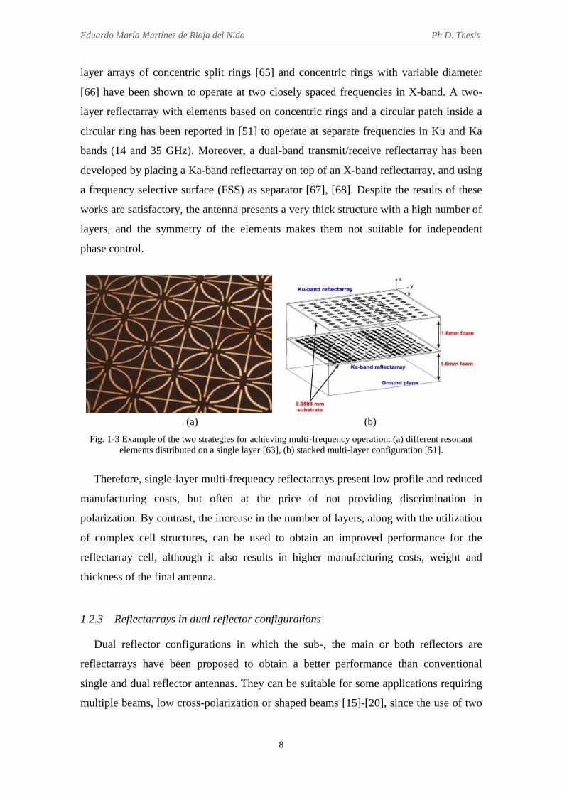
Eduardo María Martínez de Rioja del Nido Ph.D. Thesis
8
layer arrays of concentric split rings [65] and concentric rings with variable diameter
[66] have been shown to operate at two closely spaced frequencies in X-band. A two-
layer reflectarray with elements based on concentric rings and a circular patch inside a
circular ring has been reported in [51] to operate at separate frequencies in Ku and Ka
bands (14 and 35 GHz). Moreover, a dual-band transmit/receive reflectarray has been
developed by placing a Ka-band reflectarray on top of an X-band reflectarray, and using
a frequency selective surface (FSS) as separator [67], [68]. Despite the results of these
works are satisfactory, the antenna presents a very thick structure with a high number of
layers, and the symmetry of the elements makes them not suitable for independent
phase control.
(a) (b)
Fig. 1-3 Example of the two strategies for achieving multi-frequency operation: (a) different resonant elements distributed on a single layer [63], (b) stacked multi-layer configuration [51].
Therefore, single-layer multi-frequency reflectarrays present low profile and reduced
manufacturing costs, but often at the price of not providing discrimination in
polarization. By contrast, the increase in the number of layers, along with the utilization
of complex cell structures, can be used to obtain an improved performance for the
reflectarray cell, although it also results in higher manufacturing costs, weight and
thickness of the final antenna.
1.2.3 Reflectarrays in dual reflector configurations
Dual reflector configurations in which the sub-, the main or both reflectors are
reflectarrays have been proposed to obtain a better performance than conventional
single and dual reflector antennas. They can be suitable for some applications requiring
multiple beams, low cross-polarization or shaped beams [15]-[20], since the use of two

Chapter 1. Introduction
9
reflecting surfaces allows more degrees of freedom for the design. Also, controllable
electronic devices based on MEMS or PIN diodes can be integrated in the elements of
the sub-reflectarray, in order to provide reconfiguration of the beam [18] [26].
The use of a reflectarray sub-reflector with a parabolic main reflector has been
proposed for beam scanning applications [15] and the generation of contoured beams
[69]. In these cases, the reflectarray sub-reflector provides additional functionalities to
the dual reflector system, presenting a relatively simple design and low manufacturing
costs. For example, beam scanning in a limited range (up to ±5º) was demonstrated in
[26] by adding a progressive phase on a reflectarray sub-reflector, for a radiometer
system operating at 94 GHz.
Dual reflector configurations with a flat reflectarray as main reflector have been
proposed in [16] for space applications. The flat reflectarray allows for more efficient
packaging and deployment mechanisms than in the case of parabolic reflectors, thanks
to the use of a planar surface [14]. On the other hand, the large size of the reflectarray
results in narrowband operation, which is mainly caused by the differential spatial phase
delay. The implementation of a parabolic main reflectarray [39] would increase the
operating bandwidth, providing a smoother phase distribution on the reflectarray. The
parabolic surface would focus the beam, while the printed elements would introduce
small phase adjustments to shape or point the beam.
An efficient analysis tool has been recently developed and validated for dual-
reflector antennas, where the sub-, the main or both reflectors can be substituted by
planar or curved reflectarrays [70]. The technique is a modular approach that combines
the Method of Moments (MoM) for the analysis of each reflectarray and Physical
Optics (PO) when a main parabolic reflector is used. This method provides an accurate
prediction of gain, co-polar and cross-polar radiation patterns, and it is numerically
efficient, so it can be integrated in optimization routines for practical designs.
A dual reflectarray demonstrator has been designed to produce a collimated beam
with very low cross-polarization (30dB of cross-polar discrimination) in a wide
frequency band, covering transmit and receive frequencies in Ku-band (12-15 GHz)
[71]. The demonstrator, with a 50-cm main reflectarray and 40-cm sub-reflectarray, has
been manufactured and tested (see Fig. 1-4(a)), showing a good agreement with the
simulations and compliance with the design requirements.

Eduardo María Martínez de Rioja del Nido Ph.D. Thesis
10
Furthermore, a transportable dual reflectarray antenna has been shown in [18] to
provide a collimated beam with electronic scanning capabilities for Ku-band
bidirectional satellite links. The antenna consists of a passive sub-reflectarray and a
reconfigurable main reflectarray, and is designed to operate in the 10.7-14.5 GHz band
(reception and transmission in Ku-band). The reconfigurable reflectarray element is
based on a PIN diode, and provides large bandwidth, dual linear polarization, and 1 bit
of relative phase-shift. The main limitation of the prototype is its low radiation
efficiency, which is mainly caused by the low performance of the PIN diodes and the 1-
bit phase control.
(a) (b)
Fig. 1-4 Pictures of manufactured dual reflectarray antennas: (a) compact-range prototype for broadband operation in Ku-band [71], (b) bifocal folded antenna to produce multiple beams at 76 GHz [17].
Another interesting concept is the folded reflectarray antenna, which presents the
advantages of being low cost, low profile and low weight [72]. The folded antenna is
based on a dual centered configuration, where a linearly-polarized feed illuminates a
polarizing grid that is placed in front of a reflectarray. The reflectarray elements
introduce the required phase-shift in the incident field (previously reflected by the grid)
to collimate the beam, at the same time as providing a 90º twist of polarization, so that
the reflected field passes through the grid without blockage. This concept can be used to
design a dual reflectarray antenna when the polarizing grid incorporates an array of
printed elements. A folded dual reflectarray antenna has been demonstrated in [17] to
produce a shaped beam at 25 GHz for point-to-multipoint communications. Moreover, a
bifocal folded dual reflectarray has been shown in [19] to generate multiple beams at 76
GHz for automotive radar systems (see Fig. 1-4(b)). The drawback of the folded
configuration is that the antenna does not permit operation in dual polarization.

Chapter 1. Introduction
11
1.2.4 Multi-beam reflectarray antennas
Reflectarrays can be designed to generate multiple beams, either with a single feed
[73]-[76], or with one or more feeds per beam [12], [13], [17], [77]-[78]. In the first
case, the simplest approach consists on dividing the reflectarray surface into N sub-
arrays, so that each sub-array will radiate a beam in a different direction [73]. Note that
the power from the feed is divided between the N sub-arrays, each using only 1/N of the
antenna aperture. A more efficient method, which uses the entire antenna aperture to
produce N beams, is based on the superposition of the aperture fields associated to each
beam to obtain the required phase-shift distribution on the reflectarray [4] (Ch. 7). A
reflectarray with two beams separated 55º was designed by this technique to operate in
dual-LP at 11.95 GHz, using two layers of stacked patches, and the fabricated
breadboard was tested with satisfactory results [74]. The same concept was used to
design a reflectarray with four symmetric beams at 32 GHz [75], and then, particle
swarm optimization (PSO) procedures were carried out to produce four asymmetric
beams [76]. In the latter case, the phase distribution on the reflectarray shows very sharp
variations, which produces some beam distortions and very narrow bandwidth. Other
alternatives for single-fed multi-beam reflectarrays consider the use of multi-resonant
elements to produce different beams at closely spaced frequencies, as in [63].
On the other hand, reflectarrays can be used to generate multiple beams in a single
feed per beam (SFPB) scheme, following a similar design process to the case of multi-
fed reflectors. The SFPB configuration is commonly used in multi-beam applications
requiring several simultaneous beams that must be generated independently, as in
current satellite antennas in Ka-band. In this case, the reflectarray is designed to
produce a collimated beam in a given direction for a feed located at the antenna focus.
When the reflectarray is illuminated by a cluster of feeds placed near to the primary
feed, the antenna produces additional beams in different directions. If the reflectarray is
able to discriminate in frequency or polarization, each feed can generate more than one
beam [13], [59]. A reflectarray breadboard providing three simultaneous shaped beams
in Ka-band (25.5 GHz) in a SFPB basis has been reported in [77], with application to
base station sectored antennas for point-to-multipoint communications. In [13], a study
on the capability of reflectarrays to generate adjacent beams in Ka-band has been
performed, using beam squint effect to point the beams in different directions at two
closely spaced frequencies, with the drawback of very narrow bandwidth.

Eduardo María Martínez de Rioja del Nido Ph.D. Thesis
12
One of the main problems of the SFPB concept in multi-beam reflectarrays is that the
beams suffer from aberration effects due to feed defocusing. To minimize the
aberration, the positions of the feeds can be adjusted by using the same techniques than
in multi-fed reflectors [79]. Moreover, several methods have been proposed in the last
years to improve the multi-beam performance of reflectarrays. Some of these methods
are based on the optimization of the phase distribution on the reflectarray, using PSO
and genetic algorithms optimization (GAO) procedures [12], [78], which have the
disadvantage that they may result in very fast variations between the phase-shift
introduced by neighbour cells [78]. An interesting alternative to these approaches is the
application of the classic bifocal technique [80], [81] to the design of dual reflectarray
configurations, in order to obtain a better performance for the extreme beams. A multi-
beam bifocal folded reflectarray antenna operating at 76.5 GHz has been demonstrated
in [17] with quite good results, providing nine beams with up to ±24.5º scanning range.
1.3 State of the art on multi-beam satellite antennas in Ka-band
In the last decade, Ka-band has become a major alternative for satellite systems to
satisfy the growing demand for capacity and provide new broadband services. The
provision of such services is directly linked to the deployment of a high capacity
network, which maximizes the users’ throughput by fully exploiting the available
bandwidth and power resources. For this purpose, current Ka-band satellites are
required to provide a multi-spot coverage based on frequency and polarization reuse,
both in transmission (Tx, 19.2-20.2 GHz) and reception (Rx, 29-30 GHz) bands [82].
The use of multiple spot beams instead of providing a large contoured beam (as in
most broadcast Ku-band satellite applications), allows for a high degree of frequency
and polarization reuse, leading to a significant increase of the system capacity and
higher data rates for the users. A four colour reuse scheme with two frequencies and two
polarizations is normally used (see Fig. 1-5), in which adjacent spots present different
colours, meaning that they must be generated in a different frequency and/or
polarization (note that spots of the same colour are spatially isolated from each other).
On this basis, a new generation of high throughput satellites (HTS) has been developed
to provide around 100 Gb/s for broadband services using Ka-band frequencies, and it is
expected that the next HTS generation will reach several hundreds of Gb/s [83].

Chapter 1. Introduction
13
Fig. 1-5 Example of a four colour scenario for a pan-European multi-spot coverage [82].
The design of multi-beam antennas for Ka-band HTS systems [84] has become a
major issue for satellite operators, as it must cope with some challenging requirements.
In these cases, the antenna has to generate a large number of high-gain overlapping spot
beams, typically between 50 and 100. The angular spacing between adjacent spots is
considerably small (a typical value is 0.56º), in order to ensure a high value of gain at
the end of the coverage (EOC gain) [85]. This performance cannot be achieved by a
single conventional reflector, as the feed size that would provide the required beam
spacing is smaller than the feed size that ensures an optimum illumination of the
aperture (so that it may result in overlapping feeds). Therefore, either a larger F/D ratio
or electrically smaller feeds have to be used, and both solutions lead to higher spillover
losses [86]. This first option obliges to use more directive feeds, with the risk of feed
overlap, while the second option forces to increase the antenna size, resulting in more
weight on board the satellite. Moreover, the large number of spots required leads to
further deterioration of the edge beams, which are generated by the feeds with the
largest separations from the antenna focus.
In accordance with the above mentioned considerations, two main approaches are
possible for the design of multi-beam antennas to provide the four colour coverage in
Ka-band. The first approach considers the use of SFPB configurations [87]-[91], in
which each beam is generated by a single feed. Despite its hardware simplicity, the
drawback of this scheme is that several apertures are required to generate all the beams
(typically four reflectors), although using a highly-oversized shaped reflector is also
possible. On the other hand, multiple feed per beam (MFPB) systems [92]-[94] use
small clusters of feeds to produce each spot. In this case, adjacent spots can be obtained

Eduardo María Martínez de Rioja del Nido Ph.D. Thesis
14
by means of feed arrays that share some of their elements, so that two apertures can
provide multi-spot coverage for Tx and Rx in Ka-band. On the negative side, complex
and expensive beamforming networks are required to feed the elements of these arrays.
In both design approaches, SFPB and MFPB, the apertures are normally realized by
reflector antennas, which provide high gain and bandwidth with limited manufacturing
costs [84]; however, other promising alternatives are currently being investigated to
produce multi-spot coverage by using a single aperture, such as aperiodic phased arrays
[95], [96] and passive [97] and active [98] lenses.
1.3.1 SFPB antenna systems
To confront the stringent requirements of multi-spot applications in Ka-band, most of
current HTS systems carry four reflector antennas on board the satellite, each reflector
being responsible for generating all the beams in the same frequency and polarization
(same color) in a SFPB basis [82], [87]. In early versions, this solution required up to
eight reflectors: four reflectors for Tx, and four additional reflectors for Rx [88]. The
modern configuration employs only four reflectors operating both in Tx and Rx, which
are properly illuminated by Tx/Rx feed chains [82].
The four reflector configuration represents the current state of the art for multiple
spot beam antennas in Ka-band. It eliminates the problem of overlapping feeds, since
the adjacent beams in different frequencies and/or polarizations are generated by
different reflectors, allowing more room to properly accommodate the feeds that
illuminate each reflector. Low spillover can be ensured for a reasonable reflector size
(between 2 and 2.6 m in diameter), providing a large number of beams with around 50
dBi maximum gain. The four reflectors are then pointed to produce slightly overlapping
spots with 0.56º of spacing in a four colour scenario. To illustrate these concepts, Fig.
1-6 shows an example of a current HTS system operating in Ka-band (KA-SAT) [83].
From a mechanical point of view, the problem of this solution is the large number of
antennas to be accommodated in the satellite (normally occupying two lateral faces of
the satellite, as shown in Fig. 1-6(a)), as well as the large volume and weight of the
antenna system. For these reasons, it would be preferable to reduce the number of
apertures required to produce the multi-spot coverage, which would also result in lower
costs for the antenna farm.

Chapter 1. Introduction
15
(a) (b)
Fig. 1-6 Current state of the art for Ka-band HTS systems: (a) illustration of the KA-SAT with four reflectors [87], and (b) generation of the multi-spot coverage with a four colour scheme [82].
An interesting alternative is the use of three reflectors in a SFPB basis to provide a
three colour scenario, as has been reported in [89]. However, when compared to the
conventional four reflector solution of similar aperture size, this configuration presents
higher spillover losses, which results in a slight degradation of the EOC gain.
Furthermore, the use of a single reflector antenna to produce all the beams (the four
colours), leads to a highly oversized reflector, around 4.5 m in diameter, which provides
the required 0.56º of spacing by using smaller (less directive) and non-overlapping
feeds, at the same time as keeping low spillover [90], [91]. Note that the area of the
oversized reflector is comparable to the total area of the previous four reflector solution,
so it does not represent a significant improvement. Moreover, the oversized reflector has
to be shaped in order to produce wider beams, so that a high EOC gain can be reached
for all the beams (a spot diameter of 0.65º is typically considered).
1.3.2 MFPB antenna systems
The number of reflectors in the current state-of-the-art HTS antenna systems can be
reduced by using a MFPB scheme, in which each beam is produced by a cluster of small
feed-horns. Since the adjacent clusters of feeds share some of their elements, they are
able to produce overlapping spot beams, as can be seen in Fig. 1-7).

Eduardo María Martínez de Rioja del Nido Ph.D. Thesis
16
Fig. 1-7 Feed system of a MFPB antenna with shared horns to provide overlapping spots [82].
In [92], two reflectors have been designed in a MFPB basis to provide the multi-spot
coverage, with one reflector operating at Tx and the other at Rx. This configuration
allows to separately optimize the size of each reflector according to the operating band.
An alternative MFPB concept has been recently proposed based on a dual reflector
configuration with a dichroic (frequency selective) sub-reflector, providing full Tx/Rx
multi-spot coverage by the use of a single main aperture [93]. These solutions represent
a significant reduction in weight and volume of the antenna farm, facilitating the
accommodation of the antennas on board the satellite. However, the previous
advantages are achieved at the expense of implementing complex and expensive
beamforming networks [94]. Moreover, the performance of the MFPB solution is
slightly inferior to that of the equivalent SFPB configuration with the same aperture
size, and they are not suitable for providing non-regular spot lattices with different beam
sizes [82]. For these reasons, the use of MFPB antennas for current multiple spot beam
satellite applications in Ka-band is not widely spread, and these systems are still under
development.
1.4 Motivation and goals of the thesis
As has been shown in the previous section, current multi-spot satellite antennas in
Ka-band employ a large number of apertures (typically four) to generate a coverage
made of overlapping spot beams in a SFPB basis, with a four colour frequency and
polarization reuse scheme. This solution is simpler than the alternative MFPB systems
in terms of hardware and ensures low spillover for a reasonable reflector size, but it
presents some drawbacks derived from its mechanical complexity.

Chapter 1. Introduction
17
The ability of reflectarray antennas to provide independent control of the phase in
different polarizations and/or frequencies can be of particular interest for this kind of
multi-beam applications in Ka-band, leading to a potential reduction in the number of
antennas required to provide the full coverage. This would result in significant savings
in the cost, weight and volume of the antenna farm in current HTS systems in Ka-band.
However, there are some issues that must be previously addressed.
First, the design of such an antenna requires to count on appropriate reflectarray cells
that will provide an independent control of the phase at each frequency band (Tx and
Rx) and/or polarization. As shown in section 1.2, the dual-frequency reflectarray cells
that have been reported so far do not allow independent control of each polarization at
both operating frequencies. Moreover, the performance of the reflectarray antenna
should be optimized (in terms of gain, beamwidth, side-lobe levels, etc.) to generate a
large number of beams in a SFPB basis, and the capability of the antenna to provide
adjacent beams with a very small separation (around 0.56º) should be evaluated. With
this considerations in mind, the following objectives are set:
1.4.1 Design of dual-frequency and dual-polarization reflectarrays
A dual-polarization reflectarray cell will be proposed for operation at two separate
frequencies, providing independent control of the phase-shift introduced in each linear
polarization and frequency. The proposed cell is based on previous developments
regarding the design of broadband multi-resonant cells that use parallel edge coupled
dipoles [29], [30]. A two layer configuration with stacked sets of parallel dipoles will be
proposed, in which the calculation of the appropriate dipoles’ lengths will be carried out
separately for each layer, leading to a simpler and computationally faster design
process. The cell dimensions will be adjusted to allow operation first at Tx frequencies
in Ku and Ka bands (12 and 20 GHz), and then at Tx and Rx frequencies in Ka-band
(20 and 30 GHz). Several dual-band reflectarrays will be designed using the previous
cells and the aforementioned step-by-step design process. The reduced number of layers
and the simplicity of the printed elements will allow an easier manufacturing and low
profile for the resulting antenna.

Eduardo María Martínez de Rioja del Nido Ph.D. Thesis
18
1.4.2 Experimental validation of the proposed concept for dual-frequency reflectarray
antennas
A dual-band reflectarray demonstrator of 25-cm diameter will be designed,
manufactured and tested in order to validate both the proposed concept for the
reflectarray cell and the design procedure of the antenna. A home-made full-wave
electromagnetic code will be used for the analysis and design of the reflectarray. This
tool is based on the application of the Method of Moments in the Spectral Domain (SD-
MoM) and the local periodicity approach, and has been validated in previous works
[30]. The measured radiation patterns of the fabricated demonstrator will be compared
with those provided by the SD-MoM electromagnetic code, and the performance of the
antenna will be evaluated.
1.4.3 Development of a bifocal design method for dual reflectarray configurations
Concerning the antenna performance for the generation of a large number of beams
and its capability to provide closely spaced beams, the application of the classic bifocal
technique [80], [81] to dual reflectarray configurations will be proposed in this thesis.
The bifocal technique will provide better results for the extreme beams, at the same time
as permitting a certain degree of control over the spacing obtained between adjacent
beams. The previous works on this topic considered centered and rotationally-
symmetrical antenna geometries [17], which have the advantage of a simplified design
process. Offset configurations would be more suitable for the intended application
(multi-beam satellite antennas), as they will minimize blockage from the sub-reflector
and allow operation in dual polarization. Therefore, a bifocal design procedure will be
developed for offset dual reflectarray configurations with a large main reflectarray. For
this purpose, two different approaches will be considered: starting from an axially-
symmetrical configuration which allows the rotation of a 2D design around the antenna
symmetry axis [80], and implementing a 3D bifocal method that directly provides the
required phases on both reflectarrays in the selected offset configuration [81].
1.4.4 Design of bifocal dual reflectarray configurations for multi-beam satellite
antennas in Ka-band
The proposed bifocal method will be applied to different dual reflectarray
configurations for the design of multi-beam satellite antennas in Ka-band. The bifocal

Chapter 1. Introduction
19
technique will allow to reduce the beam spacing with respect to the equivalent single-
focus antenna for the same feed separation (so that such beam spacing could not be
achieved by the monofocal antenna, as it would produce overlapping feeds). The
performance of the bifocal technique will be evaluated for the provision of adjacent
beams with 0.56º of spacing, which implies a high degree of beam spacing reduction
(by a factor of 2). The use of the bifocal technique to obtain a better performance for the
extreme beams providing the same beam spacing than the equivalent monofocal antenna
will be also considered.
1.4.5 Experimental validation of the proposed bifocal design method
A bifocal dual reflectarray demonstrator will be designed, manufactured and tested in
order to validate the proposed bifocal method and corroborate the advantages of the
bifocal antenna over the equivalent single-focus design. With this aim, the bifocal
antenna demonstrator will provide a reduced beam spacing and an improved
performance for the extreme beams with respect to the equivalent monofocal antenna
with the same configuration. A home-made analysis tool implementing the modular
technique described in [70] will be used for the analysis of the dual reflectarray antenna.
The accuracy of this tool has been validated in previous works, concerning the design,
manufacturing and test of a dual reflectarray demonstrator with reduced cross-polar
levels [71]. The measured radiation patterns of the bifocal antenna demonstrator will be
compared with those computed by this analysis tool.
1.4.6 Application of the bifocal technique to dual transmitarray configurations
The developed bifocal procedure will be applied to the design of dual transmitarray
antennas. The use of transmitarrays presents some advantages, as it eliminates blockage
from the feeds and the first transmitting structure, allowing for the utilization of
centered-fed configurations with rotational symmetry (thus resulting in a simplified
design process). In addition, the transmitarray configuration is less sensitive to surface
distortions than reflector or reflectarray antennas. The particularities of the bifocal dual
transmitarray antenna with respect to the counterpart dual reflectarray will be studied.
Finally, the design of bifocal dual transmitarray antennas for multi-beam applications in
Ka-band will be addressed in a similar way to the case of dual reflectarrays.

Eduardo María Martínez de Rioja del Nido Ph.D. Thesis
20
1.5 Thesis organization
This thesis is divided into eight chapters. This chapter contains the current state of
the art on reflectarray antennas and multi-beam satellite antennas in Ka-band, and
introduces the motivation and objectives of the thesis. The rest of the chapters are
organized as follows:
Chapter 2 proposes a novel reflectarray element for independent operation at two
separate frequencies, which provides independent phase control in each
polarization at both frequencies. The reflectarray cell is based on a two-layer
configuration with stacked sets of coupled parallel dipoles for controlling each
linear polarization. The lengths of the dipoles can be separately adjusted for each
layer, according to the required phase-shift distributions on the reflectarray at
each design frequency. A 25 cm Ku/Ka-band reflectarray demonstrator has been
designed, manufactured and tested to validate the proposed reflectarray cell and
the antenna design procedure. Then, the element dimensions are modified to
allow operation at Tx and Rx frequencies in Ka-band (20 and 30 GHz), and the
element is used for the design two reflectarray antennas: a 1.6 m satellite antenna
to produce adjacent beams in orthogonal polarizations both at Tx and Rx bands,
and a 20 cm terminal antenna that generates a focused beam in dual polarization.
Chapter 3 presents a bifocal design procedure for dual reflectarray antennas in
offset configurations, starting from a rotationally-symmetrical geometry where
the two reflectarrays are placed in parallel planes. Then, the reflectarrays can be
tilted a certain angle to obtain smoother phase distributions. A preliminary study
on the bifocal technique for the design of multi-beam satellite antennas in Ka-
band is presented in this chapter, considering two main cases: reduction of beam
spacing by a factor of 2 (in order to provide adjacent beams with 0.56º of
spacing), and improvement of the multi-beam performance with respect to the
equivalent monofocal antenna (in this case, without compressing the beams).
Chapter 4 contains the application of the bifocal method described in Chapter 3
to the design of bifocal dual transmitarray antennas. In this case, the absence of
blockage allows for the use of centered and rotationally symmetrical geometries,
which results in a simplified design process. Different configurations regarding

Chapter 1. Introduction
21
the positioning of the feeds and the two transmitarrays have been studied, in
order to facilitate the practical implementation of such an antenna. Then, the
bifocal technique is used to design dual transmitarray configurations with a high
degree of beam spacing compression.
Chapter 5 describes a 3D bifocal design method for dual reflectarray antennas,
which is a more general procedure than the one shown in Chapter 3. This
technique can be applied to obtain the required bifocal phase distributions on
each reflectarray, without any restrictions in the antenna geometry. The technique
is validated for an axially-symmetrical configuration, and then used to design a
multi-beam antenna in an offset compact-range configuration. The phase
distributions and radiation patterns of the bifocal antenna are studied for three
different design cases (no beam spacing compression, low beam spacing
compression and high beam spacing compression), and compared with those
provided by the equivalent monofocal antenna.
Chapter 6 shows the design, manufacturing and testing of a bifocal dual
reflectarray antenna demonstrator, in order to validate the bifocal technique
presented in Chapter 4. The antenna presents a compact-range configuration,
with a main reflectarray of dimensions 57 cm x 42 cm, and has been designed to
operate in the 19.2-20.2 GHz band (transmission frequencies from a satellite in
Ka-band). The demonstrator generates 10 beams alternating in dual-linear
polarization, when the antenna is illuminated by an array of 5 contiguous feeds.
The bifocal technique allows to reduce beam spacing by a factor of 1.2 with
respect to the equivalent monofocal antenna, at the same time as improving the
performance of the extreme beams.
Chapter 7 presents the design of a bifocal dual reflectarray antenna with an
elliptical main reflectarray to provide multi-spot coverage for transmission from
a geostationary satellite operating in Ka-band. The bifocal technique is used to
produce adjacent beams in the offset plane, combined with a monofocal design in
the orthogonal plane. The interleaved beams for obtaining the full coverage are
generated in the orthogonal polarization, using the capability of reflectarrays to
discriminate in polarization. The multi-beam performance of the bifocal antenna
is compared with that of an oversized shaped reflector shown in [90]. The

Eduardo María Martínez de Rioja del Nido Ph.D. Thesis
22
proposed concept can be also applied to the design of a Tx/Rx antenna if multi-
frequency reflectarray cells are used to provide independent phasing in Tx and
Rx frequencies.
Chapter 8 summarizes the main conclusions and original contributions, presents
the future research lines, and enumerates the publications and research projects
related to the work carried out in this thesis.

23
Chapter 2
Design of reflectarrays for operation in dual polarization at two separate
frequencies
2.1 Introduction
The reflectarray element that will be proposed in this chapter is based on a two layer
configuration with two orthogonal sets of coupled parallel dipoles. This type of multi-
resonant cell was intended to take advantage of the lateral coupling between the dipoles
for reaching a single-layer broadband element [55], e. g., the unit cell based on three
coplanar parallel dipoles provides a similar performance in terms of bandwidth and
phase range to that of three stacked rectangular patches, with the additional benefits of
being cheaper and easier to manufacture [99]. The idea of placing two orthogonally-
arranged sets of coupled dipoles printed on the same layer, but shifted half-a-period, has
been used for the design of broadband reflectarrays in Ku-band with independent phase
control in each linear polarization [29], [30]. A new modification in this type of cell,
which consists of adding a group of parallel dipoles on a second level of metallization,
will be introduced to demonstrate the capability of reflectarrays to provide independent
phase control in each linear polarization at two separate frequencies.
The proposed element can be used to design a reflectarray antenna which is able to
fulfill independent requirements at each frequency and/or polarization. For example, in
the case of a satellite transmit antenna, a contoured beam can be generated in Ku-band
by optimizing the elements on the lower layer [7], [8], and at the same time, multiple
spot beams can be obtained in Ka-band by properly designing the elements on the top
layer [13], considering different feed chains for each mission. The implementation of

Eduardo María Martínez de Rioja del Nido Ph.D. Thesis
24
different missions on the same reflectarray antenna would result in significant savings
in the costs, weight and volume of the antenna farm, especially in the case of
telecommunication satellites that operate in Ku and Ka bands.
In the next sections, several dual polarized reflectarray antennas will be designed by
using the proposed element to operate independently in the transmit frequencies (from
the satellite) in Ku (11-13 GHz) and Ka (19-20 GHz) bands, and in the Ka-band
transmit (19-20 GHz) and receive (29-30 GHz) frequencies. Furthermore, a 25-cm
Ku/Ka-band reflectarray antenna demonstrator that generates a focused beam in dual-
polarization using different feeds for each band has been designed, manufactured and
tested, in order to validate the concept.
2.2 Dual polarized reflectarray to operate in Ku and Ka bands
A preliminary design of a dual polarized reflectarray antenna to operate at two
separate frequencies in Ku and Ka bands (11.95 and 20 GHz) is presented in this
section. First, the structure of the reflectarray cell and its operating principle are
described in detail, and two variations of the same baseline configuration are proposed
for the design of the cell. Then, the element dimensions are adjusted in both cell
configurations to allow simultaneous operation in dual polarization at 11.95 and 20
GHz. Finally, a 33 cm circular reflectarray is designed by using the previous elements,
and its performance is evaluated by means of full-wave electromagnetic simulation.
2.2.1 Design of the reflectarray cell
Two reflectarray cells based on a stacked two-layer structure and orthogonal sets of
parallel dipoles are studied. The difference between the two alternative configurations
for the cell relies on the number of coupled dipoles on the lower layer. These
configurations have been selected with the aim of providing independent phases in dual
polarization at two different design frequencies, by means of a simple reflectarray
element (only two layers) that will lead to a low-cost antenna.
2.2.1.1 Two layer reflectarray cell with six dipoles for each polarization
The basic periodic element, shown in Fig. 2-1, consists of two orthogonal sets of
dipoles. Each set comprises three coplanar parallel dipoles printed on a dielectric layer
(named layer A), and three additional parallel dipoles, which are stacked above the

Chapter 2. Design of reflectarrays for operation in dual polarization at two separate frequencies
25
previous ones and are printed on the top of a second dielectric sheet (layer B). The
lateral dipoles of each arrangement are symmetrical with respect to the central dipole, in
order to keep low levels of cross-polarization [30]. The toll to be paid with this
constraint is that some degrees of freedom are lost when adjusting the phase for each
frequency and polarization.
Fig. 2-1 View of the reflectarray periodic structure, including four unit-cells for X polarization and one
unit-cell for Y polarization.
Phase shifting can be implemented by adjusting the lengths of all dipoles in the way
that follows. The phase introduced in X polarization will be controlled by the lengths of
the dipoles in the direction of the x-axis, whereas the phase introduced in Y polarization
will be achieved with the appropriate lengths of the dipoles in the direction of the y-
axis. Similarly, the dipoles on the lower layer will adjust the phases in Ku-band, while
the dipoles on the higher layer will provide the pashing in Ka-band.
The dual-frequency operating principle works because of the difference in the
dimensions of the elements between the two layers. Since the dipoles on the top layer
will be shorter than those on the bottom layer, the phase response of the unit-cell at the
lower design frequency (in this case, 11.95 GHz) will not be affected by the length of
the upper dipoles. Although it is not reciprocal, because the phase response at the higher
design frequency (20 GHz) will slightly depend on the length of the lower dipoles, in a
certain way the lower dipoles will behave as a ground plane for higher layer elements.
In practice, the longer dipoles on the bottom layer will add a reactance (phase-shift) at
the higher frequency that must be compensated in the design process.
Eduardo María Martínez de Rioja del Nido Ph.D. Thesis
26
A period of 10 mm, which is 2·λ/3 at 20 GHz, has been fixed for the horizontal (PX)
and vertical (PY) dimensions of the cell. This period has been chosen to provide both,
enough room for the dipoles and enough range of phase-shift in the lower band, and at
the same time, to avoid grating lobes as much as possible in the higher band,
considering a maximum angle θ = 30º (angle of incidence from the feed on the
reflectarray elements or angle of the radiated beam), according to the expression
provided in [4] (p. 84):
𝑃 ≤𝜆
1 + sin 𝜃 (2-1)
Commercially available materials have been used to implement both dielectric
layers: the lower layer is an AD255C sheet, while the upper substrate is a Diclad 880B
sheet. The electrical properties and thickness of the two dielectric layers are: relative
permittivity εrA = 2.55, εrB = 2.17; loss tangent tanδA = tanδB = 0.0009; and thickness hA
= 2.363 mm, hB = 1.524 mm.
A parametric study has been carried out by changing the different geometrical
parameters (width, separation and ratio of lengths for the dipoles) and finally, the
following parameters have been chosen to provide a smooth variation in phase response
and cover a wide range of phase (≥360º) in both frequency bands: dipole width w = 0.5
mm; separations between laterally coupled dipoles SXA = SYA = 1.5 mm, SXB = SYB =
1.5 mm; and relative sizes of the lateral dipoles lA1 = 0.63·lA2, lA3 = 0.63·lA4 (where lA2
and lA4 correspond to the lengths of the central dipoles in the lower layer), lB1 = 0.78· lB2,
lB3 = 0.7·lB4 (where lB2 and lB4 correspond to the lengths of the central dipoles in the
upper layer).
2.2.1.2 Two layer reflectarray cell with eight dipoles for each polarization
An alternative reflectarray cell has been proposed (see Fig. 2-2) following the same
operating principle than the element presented in the previous section. It comprises two
sets of five coplanar parallel dipoles printed on the lower dielectric layer (layer A), and
three parallel dipoles stacked above the first sets and printed on the top of a second
dielectric sheet (layer B). The reason for introducing this modification on the cell (two
additional dipoles on the lower layer for each linear polarization) is to obtain greater
stability in the phase response at the higher frequency and to provide an additional
length variable for implementing the design process in each polarization.

Chapter 2. Design of reflectarrays for operation in dual polarization at two separate frequencies
27
The cell period is chosen again as PX = PY = 10 mm. After a parametric study, the
following parameters have been selected to obtain a smooth phase variation and a wide
range of phase-shift in both frequency bands: dipole width w = 0.5 mm; edge-to-edge
separations between dipoles SXA = SYA = 0.5 mm, SXB = SYB = 1.5 mm; and relative
sizes of lateral dipoles lA1 = 0.59·lA3, lA2 = 0.75·lA3, lA4 = 0.59·lA6, lA5 = 0.75·lA6 (where
lA3 and lA6 correspond now to the central dipoles’ lengths in the lower layer), lB1 =
0.8·lB2, lB3 = 0.8·lB4.
Fig. 2-2 View of the reflectarray periodic structure, including four unit-cells for Horizontal polarization
and one unit-cell for Vertical polarization.
2.2.1.3 Comparison of phase and amplitude curves
The simulated phase and amplitude curves of the co-polar reflection coefficient are
shown in Fig. 2-3 for both proposed reflectarray cells, considering X-polarization and
oblique incidence, θi = 20º and φi = 0° (which is related to the elements located on the
central part of the reflectarray that will be designed in the next section). Note that the
response in both polarizations is identical for normal incidence. In this case (θi = 20º), a
similar response is obtained for Y-polarization, although the results are not shown here.
The results in Fig. 2-3 are presented as a function of the lengths of the central dipoles
in the direction of x-axis: the lower central dipole in Fig. 2-3(a), and the upper central
dipole in Fig. 2-3(b). Note that the lengths of the lateral dipoles are also varied, while
keeping the relations given above between their lengths and those of the central dipoles.
As can be seen, the phase and amplitude curves are similar for both proposed
reflectarray cells, although the second configuration (8+8 dipoles) provides a wider
phase variation range in the lower frequency band. Smooth variations in phase are

Eduardo María Martínez de Rioja del Nido Ph.D. Thesis
28
achieved in both configurations, especially at Ku-band, and the encompassed phase
range is wide enough (more than 360º) to perform the dual-band design process.
Moreover, the orthogonal dipoles that control each linear polarization are practically
uncoupled, as shown in [30].
(a)
(b)
Fig. 2-3 Phase and amplitude of the co-polar reflection coefficient for X-polarization: (a) at 11.95 GHz, (b) at 20 GHz.

Chapter 2. Design of reflectarrays for operation in dual polarization at two separate frequencies
29
The phase-shift introduced at each frequency band can be mostly controlled by
adjusting the lengths of the dipoles in each layer, as shown in Fig. 2-4 for the (6+6)
dipole element (note that a similar behaviour is obtained for the second cell
configuration, although the graphics are not included here). This figure presents the
variation in the phase of the co-polar reflection coefficient with respect to the lengths lA2
and lB2 (lengths of the lower and upper central dipoles in the direction of x-axis) at 11.95
and 20 GHz, considering X-polarization and oblique incidence (θi = 20º, φi = 0º). The
phase-shift introduced at 11.95 GHz can be adjusted by the lengths of the dipoles on the
bottom layer, as shown in Fig. 2-4(a). However, the dipoles on layer A have a certain
influence on the phase response at 20GHz, see Fig. 2-4(b). This effect must be corrected
in the design process, obtaining the appropriate lengths for the dipoles on layer B once
the dimensions of the lower layer elements have been fixed.
(a) (b)
Fig. 2-4 Phase of the cell reflection coefficient (in degrees) with respect to the lengths of the central dipoles in both layers, considering X-polarization and oblique incidence (θ = 20º): (a) at 11.95 GHz and
(b) at 20 GHz.
Finally, it should be remarked that the curves shown in Fig. 2-3 are only used for the
periodic element characterization. During the subsequent design process, the real angles
of incidence on each reflectarray element (θi, φi) will be taken into account to calculate
the phase of the reflection coefficient and adjust the lengths of the dipoles. This
variation on the angles may slightly modify the trace of the phase curves in Ka-band,
while having almost no effect in Ku-band. A more detailed characterization of the
element (operating at slightly different frequencies) will be provided in section 2.3.1,
regarding the design of a limited size dual-band reflectarray demonstrator.

Eduardo María Martínez de Rioja del Nido Ph.D. Thesis
30
2.2.2 Design of a Ku/Ka-band dual polarized reflectarray antenna
A circular reflectarray with 33 cm diameter has been designed to operate in dual-
linear polarization (dual-LP) at 11.95 and 20 GHz. The reflectarray consists of 861
elements placed in a 33 x 33 circular grid, with cell size 10 x 10 mm. The antenna is
illuminated by an ideal feed-horn operating in dual-polarization and dual-frequency,
placed with a certain offset in x-axis from the broadside radiation position, according to
the absolute reference coordinate system shown in Fig. 2-5 (where the origin of the
coordinate system is located at the geometrical center of the reflectarray). The
coordinates of the horn phase center are (xF, yF, zF) = (-192, 0, 627.5) mm.
Fig. 2-5 Reflectarray antenna, with feed-horn position and reference coordinate systems.
The electromagnetic field radiated by the feed-horn has been modeled using a simple
cosq(θ) distribution (more details can be found in [100], pp. 28-29), with a q-factor
equal to 26 for Ku-band and 50 for Ka-band. Under these conditions, the illumination
levels on the reflectarray edges are close to -10.2 dB at 11.95 GHz and -11.8 dB at 20
GHz, looking for a compromise between the illumination and spillover efficiencies
which maximizes the antenna gain.
The reflectarray has been designed to produce two focused beams in the directions
θbX = 13°, φbX = 0° for X-polarization and θbY = 20°, φbY = 0° for Y-polarization both at
Ku and Ka bands, using the two types of cell described in section 2.2.1. The required
phase-shift to be introduced by each reflectarray element for a single polarization will
be achieved by adjusting the dimensions of the two stacked sets of parallel dipoles
placed on each layer, according to the phase-shift distributions shown in Fig. 2-6. These

Chapter 2. Design of reflectarrays for operation in dual polarization at two separate frequencies
31
distributions have been obtained applying the expression provided in [4] (p.34), which
relates the required phase for the cell reflection coefficient (φR) with the phase of the
incident field (radiated by the feed) on that cell and the specified direction for the
radiated beam (θb, φb):
𝜑𝑅(𝑥𝑖, 𝑦𝑖) = 𝑘0(𝑑𝑖 − sin 𝜃𝑏 (𝑥𝑖 cos𝜑𝑏 + 𝑦𝑖 sin𝜑𝑏)) (2-2)
where k0 is the propagation constant in vacuum, di is the distance from the phase center
of the feed to the cell, and (xi, yi) are the coordinates of the i-element.
(a) (b)
(c) (d)
Fig. 2-6 Phase-shift distributions (in degrees) to be introduced by the reflectarray in: (a) X-polarization at 11.95 GHz, (b) Y-polarization at 11.95 GHz, (c) X-polarization at 20 GHz, (d) Y-polarization at 20 GHz.
The dipoles with the largest lengths will be located at those elements with phase-shift
values close to -360°, according to the phase curves showed in Fig. 2-3. The majority of
these elements are placed near to the geometrical center of the antenna, which will be
the most illuminated part, with incidence angles between θi = 10° and θi = 20° (see Fig.
2-7). An appropriate election of phase constants for the simulations will be performed in

Eduardo María Martínez de Rioja del Nido Ph.D. Thesis
32
order to minimize the errors in this zone of the reflectarray, which will be decisive in
shaping the antenna radiation pattern.
(a) (b)
Fig. 2-7 Angles of incidence (in degrees) from the feed on each reflectarray cell: (a) theta, (b) phi.
2.2.2.1 Two-step design procedure for dual-band reflectarrays
As stated earlier in this chapter, the length of the dipoles in layer A will be larger
than the length of dipoles in layer B, so that upper dipoles will not disturb the
reflectarray phase response at 11.95 GHz, and lower dipoles will behave in a certain
way as a ground plane at 20 GHz for higher layer elements. Due to this operation mode,
the dipole lengths needed to match the required phase distributions on the reflectarray
can be calculated separately for each frequency band, considering only the dipoles in
one of the two layers.
First, the dipoles on the bottom layer are adjusted to provide the required phase-shift
at 11.95 GHz. Since the dimensions of the bottom layer influence the phase response at
20 GHz, the lengths of the dipoles on the top layer are adjusted to produce the required
phase at 20 GHz at each reflectarray cell, taking into account the real dimensions of the
lower dipoles previously calculated at 11.95 GHz. In this way, the effect of the bottom
dipoles on the phase response at 20 GHz (see Fig. 2-4(b)) is taken into account in the
design of the antenna. Moreover, the dipoles in the direction of the x and y axes can be
independently adjusted due to the uncoupling of the phases for the two orthogonal
polarizations, as was demonstrated in [30]. All these factors allow for performing an
easier and computationally faster design process.

Chapter 2. Design of reflectarrays for operation in dual polarization at two separate frequencies
33
To obtain the appropriate lengths for each arrangement of coplanar parallel dipoles,
it is employed a zero-finding procedure which iteratively calls a home-made software
analysis routine that applies the Method of Moments in the Spectral Domain (SD-MoM)
[29]. First, the lengths of the dipoles are gradually increased (keeping the relations
given above between the side and central dipoles’ lengths), until the phase-shift exceeds
the required value. This provides a short interval which contains the target length for the
central dipole. Then, the accuracy of this approximation is improved by applying the
Newton-Raphson method, which results in fast convergence to the target value after
only a few iterations of the algorithm. For this purpose, it is important that the
reflectarray elements present a smooth variation in the phase response at both frequency
bands (see Fig. 2-3).
The SD-MoM analysis tool used for the design of the dipoles has been developed at
the Applied Electromagnetics Group of Universidad Politécnica de Madrid (UPM), in
collaboration with the Faculty of Physics of Universidad de Sevilla. This full-wave
electromagnetic code is based on the use of multilayered Green’s functions and assumes
an infinite periodic array model for the analysis of each cell. The analysis technique is
an extension of the one presented in [101] for a reflectarray cell made of three parallel
dipoles. It computes the reflection matrix of each cell, Г, formed by the co-polar (ΓXX
and ΓYY) and cross-polar (ΓXY and ΓYX) reflection coefficients that relate the tangential
components of the incident electric field in the direction of dipoles with the tangential
components of the reflected field, as shown in eq. (2-3). For this purpose, the real angles
of incidence (θi, φi) on each reflectarray cell are taken into account.
(𝐸𝑋
𝑅𝑒𝑓
𝐸𝑌𝑅𝑒𝑓
) = (𝛤𝑋𝑋 𝛤𝑌𝑋𝛤𝑋𝑌 𝛤𝑌𝑌
) · (𝐸𝑋
𝐼𝑛𝑐
𝐸𝑌𝐼𝑛𝑐) (2-3)
The SD-MoM code provides a fast and accurate calculation tool; further details about
the validation and performance of this code can be found in [30] and [102]. This
includes a comparison between the simulated and measured radiation patterns of a 40-
cm reflectarray demonstrator with cells also made of coupled parallel dipoles, and the
significant savings in computational times that this numerical code offers over other
commercial tools, such as CST [103]. For example, the simulation time of a 24-cm
sided reflectarray at 11.95 GHz has been reduced from 8 hours (using CST without
local periodicity) to only half a minute (SD-MoM plus local periodicity) [102].

Eduardo María Martínez de Rioja del Nido Ph.D. Thesis
34
Once the design of the dipoles is completed, independently for each frequency, a
further optimization is run, in which the dimensions of all dipoles are optimized
element-by-element to simultaneously match the phases at the central and extreme
frequencies both in Ku and Ka bands. In this case, a 2 GHz bandwidth is considered in
Ku-band (10.95-12.95 GHz), while 1 GHz bandwidth is enforced in Ka-band (19.5-20.5
GHz). The optimization involves a fine adjustment of the dipoles’ lengths, following a
procedure very similar to that shown in [32]. As in the design process, the optimization
can be separately run for the dipoles in the direction of the x and y axes. In the end, the
optimization provides an improved performance for the antenna at the extreme
frequencies of the prescribed bands, at the cost of a slightly worse performance at the
central frequency of each band.
2.2.3 Results of the simulations
The simulated radiation patterns in gain (dBi) of the 33-cm reflectarray antenna are
shown in Fig. 2-8 for the design performed with the (6+6) dipole element, and in Fig.
2-9 for the design with the (8+8) dipole element, in both cases before conducting the
multi-frequency optimization. The results are presented at the central frequency of each
band (11.95 and 20 GHz), in the elevation and azimuth orthogonal planes. Note that the
elevation plane coincides with the xz-plane for both polarizations (the beams are
radiated at φ = 0º), while the azimuth planes are orthogonal to the xz and form 13º and
20º with respect to z-axis for X and Y polarizations, respectively (although the two cuts
are superimposed in the same figure). The patterns include both co-polar and cross-
polar components of the radiated field for each polarization. The electric field on the
aperture of the feed-horn has been used to compute the incident field on the reflectarray.
Then, the radiation patterns have been obtained from the tangential reflected field at
each reflectarray cell, using the aforementioned SD-MoM code.
As can be seen in Fig. 2-8 and Fig. 2-9, the patterns at the lower frequency are very
similar for both designs. The beam is focused in the direction θbX = 13°, φbX = 0° for X-
polarization and θbY = 20°, φbY = 0° for Y-polarization, as it was intended. A gain
around 30.7 dBi is reached at 11.95 GHz for the beam in X polarization, while 30.1 dBi
is achieved for the beam in Y-polarization. The side-lobe levels (SLL) are close to -21
dB with respect to the co-polar maximum for both polarizations, and the cross-polar
discrimination (XPD) is around 34 dB, measured within a 3-dB beamwidth.

Chapter 2. Design of reflectarrays for operation in dual polarization at two separate frequencies
35
(a)
(b)
(c)
(d)
Fig. 2-8 Simulated radiation patterns of the (6+6) dipole antenna: (a) xz-plane at 11.95 GHz, (b) superposition of azimuth cuts at 11.95 GHz, (c) xz-plane at 20 GHz, and (d) superposition of azimuth cuts
at 20 GHz.

Eduardo María Martínez de Rioja del Nido Ph.D. Thesis
36
(a)
(b)
(c)
(d)
Fig. 2-9 Simulated radiation patterns of the (8+8) dipole antenna: (a) xz-plane at 11.95 GHz, (b) superposition of cuts in the azimuth plane at 11.95 GHz, (c) xz-plane at 20 GHz, (d) superposition of cuts
in the azimuth plane at 20 GHz.

Chapter 2. Design of reflectarrays for operation in dual polarization at two separate frequencies
37
On the other hand, the use of the second cell structure, with eight dipoles for each
polarization, results in a more accurate beam shaping at 20 GHz (see Fig. 2-9(c) and
Fig. 2-9(d)), with an important reduction in the SLL (from -20 to -23 dB) with respect
to the design performed with the (6+6) dipole element. Moreover, the (8+8)
configuration contributes to leveling the results obtained for the beams in X and Y
polarizations. In the patterns shown in Fig. 2-8 for the (6+6) dipole antenna, the gain of
the beam produced at 20 GHz in X-polarization is 34.1 dBi, which is around 1.6 dB
higher than the gain of the beam in Y-polarization (32.5 dBi). However, in the case of
the (8+8) dipole antenna, this difference is reduced to 0.6 dB, since 34.1 and 33.5 dBi
gain is attained for the beams in X and Y polarizations, respectively. Finally, the (8+8)
dipole antenna presents a slight improvement in XPD, which is around 22.4 dB instead
of 19.2 dB, as in the case of the (6+6) dipole antenna.
It has been checked that the radiation patterns at the extreme frequencies of each
band present better results for the beams in X-polarization than for those in Y-
polarization, which show a further deterioration with respect to the patterns at the
central design frequencies, particularly in the case of Ka-band (see Fig. 2-10 to Fig.
2-15 for the (8+8) dipole antenna). After carrying out the multi-frequency optimization,
the antenna performance is improved for both polarizations at the extreme frequencies
in Ku and Ka bands (higher gain, lower SLL, better beam shaping, etc.), at the expense
of obtaining a slightly worse performance at the central frequencies. The results of the
optimization have been included in Fig. 2-10 to Fig. 2-15 for the (8+8) dipole
reflectarray, since the design made with the (6+6) configuration showed a worse
response against frequency shifts respect to the central frequencies.
In the case of X-polarization, the available bandwidth in Ku-band is around 2 GHz
centered at 11.95 GHz (16%), with a gain variation of 1 dB, while 1 GHz bandwidth is
reached at 20 GHz (5%) with the same gain variation. The optimization provides
improvements of up to 2 dB in the gain and up to 7.5 dB in the SLL for the patterns at
the extreme frequencies of both operating bands with respect to the results obtained
before the optimization. Regarding the beams in Y-polarization, the antenna presents
reasonably good results in Ku-band, where 16% bandwidth (2 GHz centered at 11.95
GHz) is achieved with a 1.3 dB gain variation and similar enhancements in the gain and
SLL of the patterns than in the case of X-polarization. However, the improvement
provided by the optimization is not sufficient to reach an acceptable performance at the
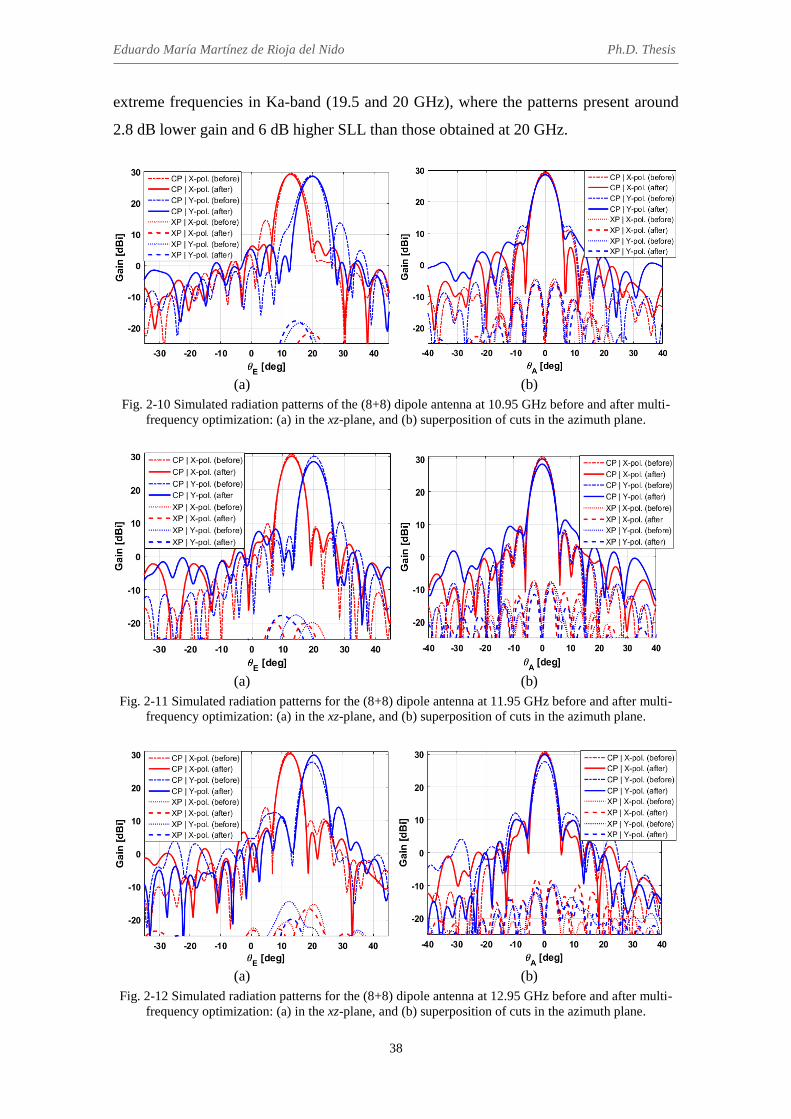
Eduardo María Martínez de Rioja del Nido Ph.D. Thesis
38
extreme frequencies in Ka-band (19.5 and 20 GHz), where the patterns present around
2.8 dB lower gain and 6 dB higher SLL than those obtained at 20 GHz.
(a) (b)
Fig. 2-10 Simulated radiation patterns of the (8+8) dipole antenna at 10.95 GHz before and after multi-frequency optimization: (a) in the xz-plane, and (b) superposition of cuts in the azimuth plane.
(a) (b)
Fig. 2-11 Simulated radiation patterns for the (8+8) dipole antenna at 11.95 GHz before and after multi-frequency optimization: (a) in the xz-plane, and (b) superposition of cuts in the azimuth plane.
(a) (b)
Fig. 2-12 Simulated radiation patterns for the (8+8) dipole antenna at 12.95 GHz before and after multi-frequency optimization: (a) in the xz-plane, and (b) superposition of cuts in the azimuth plane.
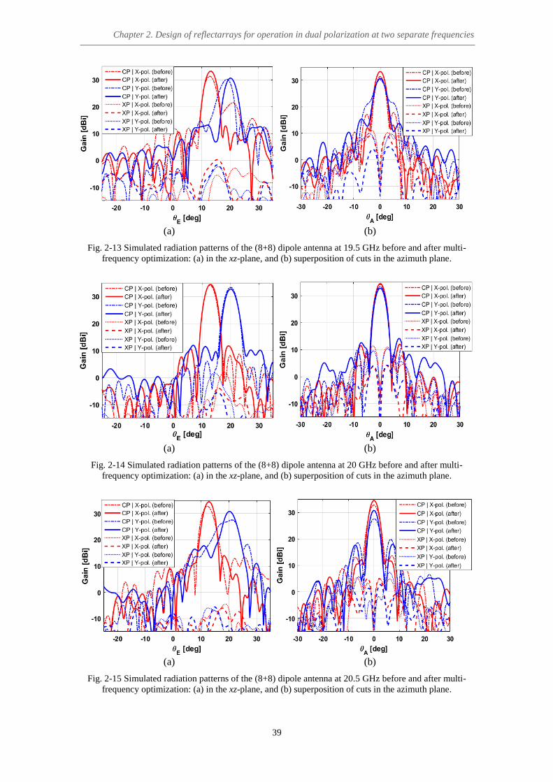
Chapter 2. Design of reflectarrays for operation in dual polarization at two separate frequencies
39
(a) (b)
Fig. 2-13 Simulated radiation patterns of the (8+8) dipole antenna at 19.5 GHz before and after multi-frequency optimization: (a) in the xz-plane, and (b) superposition of cuts in the azimuth plane.
(a) (b)
Fig. 2-14 Simulated radiation patterns of the (8+8) dipole antenna at 20 GHz before and after multi-frequency optimization: (a) in the xz-plane, and (b) superposition of cuts in the azimuth plane.
(a) (b)
Fig. 2-15 Simulated radiation patterns of the (8+8) dipole antenna at 20.5 GHz before and after multi-frequency optimization: (a) in the xz-plane, and (b) superposition of cuts in the azimuth plane.

Eduardo María Martínez de Rioja del Nido Ph.D. Thesis
40
There are several reasons for the degradation of the antenna performance at Ka-band
frequencies: the large period of the cells, which is required to provide enough range of
length variation for the lower dipoles (allowing 360º of phase-shift variation margin in
Ku-band), the presence of phase errors in the design of the upper dipoles, and the
appearance of grating lobes due to the excitation of higher order Floquet modes for
certain angles of incidence (associated to a few cells near the reflectarray edge). This
degradation of the radiation patterns in Ka-band will be studied in more detail in section
2.3.4, concerning the measurement of a Ku/Ka-band reflectarray demonstrator.
Finally, the antenna radiation efficiency is estimated at 68% in Ku-band and 54% in
Ka-band, which are typical values for conventional parabolic reflectors. Note that the
conducted simulations take into account most of the losses, such as spillover,
illumination and dielectric losses. The previous efficiencies have been be calculated as
the ratio between the simulated gain and the maximum directivity at each frequency.
The latter magnitude can be approximated using eq. (2-4), which relates the gain of the
antenna with the size of the aperture (Sap), the wavelength at the operation frequency
and the radiation efficiency (εrad). According to eq. (2-4), the maximum directivity is
obtained for εrad = 1 (100% efficiency).
𝐺 =4𝜋
𝜆2· 𝑆𝑎𝑝 · 𝜀𝑟𝑎𝑑 (2-4)
2.2.4 Conclusions
A 33-cm diameter circular reflectarray antenna has been designed to operate in Ku
and Ka bands (11.95 and 20 GHz) with independent beams in each linear polarization.
The proposed cell structure for the reflectarray element consists of two stacked layers,
each of them comprising two orthogonal sets of coplanar parallel dipoles. The element
enables independent phasing in each linear polarization at both design frequencies. Two
variations of this structure have been studied, providing four and five degrees of
freedom for each polarization.
The lengths of the dipoles have been optimized to meet the required phase-shift
distributions at each frequency band and polarization. For this purpose, a two-step
design procedure has been implemented, in which the appropriate lengths of the dipoles
are computed first for the elements on the lower layer (according to the phases at 11.95

Chapter 2. Design of reflectarrays for operation in dual polarization at two separate frequencies
41
GHz), and then for those at the upper layer (according to the phases at 20 GHz). This
staged procedure allows for a simpler and computationally faster design process. The
conducted simulations show a good behaviour of the antenna in both frequency bands,
with gain values greater than 30 dBi and SLL close to -20 dB. A better performance at
the higher frequency band is obtained for the reflectarray designed using the second cell
structure, with eight dipoles for controlling the phase in each linear polarization.
These results show the potential of reflectarray antennas for working at different
bands, with independent beam shaping in each polarization and band. Furthermore, the
ease of integration and the reduction in cost, with only two layers of printed elements,
are clearly appreciated. This may be a key factor in communication satellites that
operate in Ku and Ka bands, where volume and weight are determining issues. The next
step will involve the design, manufacturing and measurement of a reflectarray prototype
to corroborate the results of these simulations and validate the design concept.
2.3 Design, manufacturing and test of a dual polarized reflectarray
demonstrator to operate in Ku and Ka bands
Telecommunication satellites require an increasingly larger number of antennas to
provide fixed services in Ku-band and broadband access in Ka-band [86], [87]. A major
trend is to accommodate multiple payloads for different functions in the satellite.
Dichroic sub-reflectors have been proposed to enable the reuse of the same main
reflector for Ku- and Ka-band missions [104], or for both Tx and Rx operation in Ka-
band [84], [93]. This will provide a significant saving of space in the satellite, at the
same time as allowing to separate the feed chains for each frequency band. However,
the use of such frequency selective surfaces (FSS) in telecommunication antennas is not
straightforward, because the reflector has to be optimized in a different way for each
mission. For example, whereas the reflector is typically shaped in Ku-band to provide a
contoured coverage, it should provide multiple spots in Ka-band, and in both cases
stringent requirements in gain, cross-polar and co-polar isolation are needed [87].
The reflectarray element proposed in the previous section can be applied to design a
satellite transmit antenna, which is optimized to fulfill the requirements for two
simultaneous missions in Ku and Ka bands, considering different feed chains for each
mission. For example, a contoured beam can be generated in Ku-band by optimizing the

Eduardo María Martínez de Rioja del Nido Ph.D. Thesis
42
dipole lengths in the lower layer as in [30], and at the same time, multiple spots can be
obtained in Ka-band by optimizing the dipoles on the upper layer [13], having more
room to properly accommodate the feed chains of each mission. This kind of space
applications will require a large reflectarray antenna, around 1.5 m in diameter. As a
proof of concept, a limited sized demonstrator that generates a focused beam in dual-
polarization using different feeds for Ku and Ka bands has been designed, manufactured
and tested.
The proposed reflectarray is able to operate independently in the transmit frequencies
in Ku-band (11-13 GHz) and Ka-band (19-20 GHz), but similar reflectarray cells can be
designed to operate in the receive frequencies (13.75-14.80 GHz in Ku-band and 29-30
GHz in Ka-band). This technology permits an independent optimization of the radiation
patterns and position of feed-chains for spacecraft antennas in Ku and Ka bands.
Although it obliges to separate transmit and receive antennas, the reuse of the same
aperture for Ku and Ka missions would lead to significant savings in the costs, weight
and volume of the antenna farm in telecommunication satellites that operate at those
frequency bands.
2.3.1 Design of the reflectarray cell
The unit-cell used to provide the phasing in the reflectarray presents the same
structure than the one described in section 2.2.1.2 (see Fig. 2-2). It is composed of two
orthogonal arrangements of eight parallel dipoles, which are distributed on a two-layer
configuration: there are five parallel dipoles on the lower layer (layer A), and three
stacked dipoles on the higher layer (layer B). This configuration has been selected since
it provides a better performance at the higher frequencies than the alternative cell with
six dipoles for each polarization (see section 2.2.3). The geometrical parameters of the
cell (period, dipole width, separation between adjacent dipoles, ratio of lengths for the
side and central dipoles) are the same than were indicated in section 2.2.1.2. Moreover,
the two dielectric layers are implemented by the same materials, AD255C (layer A) and
Diclad 880B (layer B).
In this case, the central design frequencies in Ku- and Ka-band will be 12 and 19.5
GHz, respectively. Note that the higher frequency has been slightly reduced with respect
to the previous design (20 GHz), in order to obtain a better performance of the antenna
in Ka-band. Fig. 2-16 shows the results for the module and phase of ΓXX (co-polar
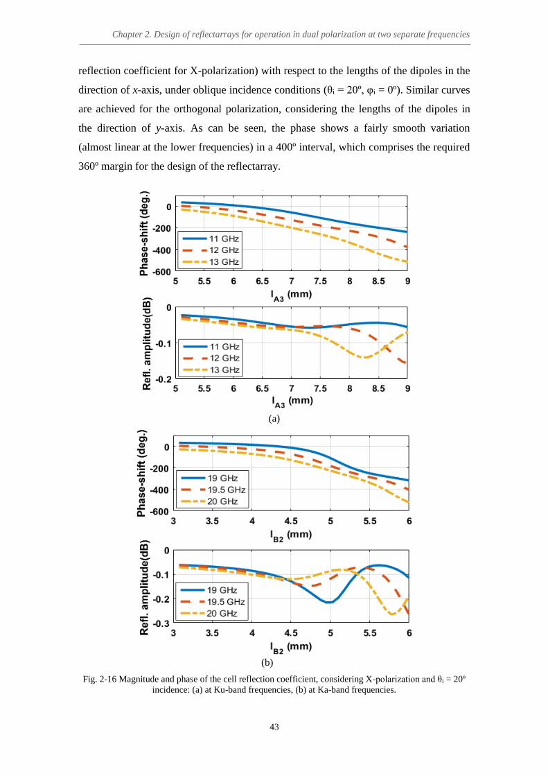
Chapter 2. Design of reflectarrays for operation in dual polarization at two separate frequencies
43
reflection coefficient for X-polarization) with respect to the lengths of the dipoles in the
direction of x-axis, under oblique incidence conditions (θi = 20º, φi = 0º). Similar curves
are achieved for the orthogonal polarization, considering the lengths of the dipoles in
the direction of y-axis. As can be seen, the phase shows a fairly smooth variation
(almost linear at the lower frequencies) in a 400º interval, which comprises the required
360º margin for the design of the reflectarray.
(a)
(b)
Fig. 2-16 Magnitude and phase of the cell reflection coefficient, considering X-polarization and θi = 20º incidence: (a) at Ku-band frequencies, (b) at Ka-band frequencies.

Eduardo María Martínez de Rioja del Nido Ph.D. Thesis
44
The element response has been studied for different angles of incidence (see Fig.
2-17), showing slight variations of phases in Ka-band and almost no effect on the
phases in Ku-band. To avoid any possible errors in Ka-band, the calculation of the
reflection coefficients will take into account the real angles of incidence from the feed
in the design and analysis of the antenna.
(a)
(b)
Fig. 2-17 Phase of the cell reflection coefficient for X-polarization under different angles of incidence: (a) at 12 GHz, (b) at 19.5 GHz.
Moreover, Fig. 2-18 shows the variation in phase of ΓXX and ΓYY co-polar reflection
coefficients with respect to the lengths of upper and lower dipoles in the corresponding
directions, at 12 and 19.5 GHz for (θi = 20º, φi = 0º) angles of incidence. The element
phase response at 12 GHz can be completely controlled by the lengths of the lower
dipoles, which means that the design of the bottom layer at 12 GHz can be carried out
without considering the dipoles on the higher layer. However, this is not exactly true for
the design of the higher layer at 19.5 GHz, since there is certain dependence between
the lengths of upper dipoles and the lengths previously calculated for the lower ones,
which may slightly affect the phase response of the element. Despite this fact, once the
lower layer dimensions have been fixed, there is still enough phase range to implement
the required phases at 19.5 GHz with the lengths of upper dipoles.

Chapter 2. Design of reflectarrays for operation in dual polarization at two separate frequencies
45
(a) (b)
(c) (d)
Fig. 2-18 Phase (in degrees) of the cell reflection coefficient with respect to the lengths of the dipoles in both layers, at 12 GHz (a) for X-polarization and (b) for Y-polarization; and at 19.5 GHz (c) for X-
polarization and (d) for Y-polarization.
Therefore, almost independent design processes can be performed for each layer, as
was indicated in section 2.2.2. For example, the dipoles on the lower layer can be
designed to generate a contoured beam in Ku-band by fitting the appropriate phase
distributions in that band. Then, keeping fixed the dipoles in the lower layer, the dipoles
on the upper layer can be adjusted to match different phase-shifts, for example to fulfill
the requirements for multi-beam operation in Ka-band. The implementation of this step-
by-step method simplifies the design of the antenna, and causes an important reduction
in computational times. Possible phase errors can be corrected by means of an
additional optimization that will be run after the design process.
2.3.2 Design of the demonstrator
A Ku/Ka-band reflectarray antenna demonstrator, comprising 625 elements disposed
in a 25 x 25 grid (250 mm sided antenna), has been designed, manufactured and tested,
in order to show the capability of reflectarrays to provide independent phase control at

Eduardo María Martínez de Rioja del Nido Ph.D. Thesis
46
two frequencies and two polarizations. The reflectarray will produce a collimated beam
in dual polarization at 12 and 19.5 GHz. The beam will radiate in the direction θb = 20°,
φb = 0° at both design frequencies.
Two pyramidal feed-horns have been employed to illuminate the antenna in an offset
configuration. The phase centers of the horns are located at the following coordinates,
according to the reference system shown in Fig. 2-19: (xF1, yF1, zF1) = (-114, 0, 223) mm
for Ku-band horn; and (xF2, yF2, zF2) = (-62, 0, 247) mm for Ka-band horn. The angle of
radiation (20º) has been chosen to avoid blockage from the feeds, and also to maintain
an intermediate value between the angles subtended by the two horns and the z-axis
from the reflectarray center, which are 14º and 27º (see Fig. 2-19).
Fig. 2-19 Schematic view of the reflectarray and the two feed-horns in the symmetry plane (y = 0).
Conventional cosq(θ) functions, based on electromagnetic simulations of both horns,
have been used to model their radiation patterns. The Ku-band horn (model
VT140SGAH15SK from Vector Telecom), with a gain at 12 GHz of 14.47 dBi and a 3-
dB beamwidth of 30°, is modelled with q = 10. On the other hand, the Ka-band horn
(model NARDA 638) presents 15.6 dBi gain at 20 GHz, the 3-dB beamwidth is 26.7°,
and q = 13 has been used for the simulations. Under these conditions, the following
illumination levels are reached on the reflectarray edges: -9.8 dB at 12 GHz and -13.8
dB at 19.5 GHz.

Chapter 2. Design of reflectarrays for operation in dual polarization at two separate frequencies
47
The phase-shift distributions required on the reflectarray to generate a collimated
beam in the specified direction at 12 and 19.5 GHz are shown in Fig. 2-20 for both
polarizations (with the electric field in the direction of the dipoles). Since the antenna is
designed to provide the same radiation pattern for the two orthogonal components of the
incident field, it will operate in dual-circular polarization (CP) when illuminated by a
dual-CP polarized feed. This flexibility may be particularly useful for a multi-mission
space antenna, as most of Ku-band transponders operate in linear polarization, while
circular polarization is commonly employed in Ka-band transponders.
(a) (b)
Fig. 2-20 Required phases (in degrees) to be implemented on the reflectarray surface in X and Y polarizations: (a) at 12 GHz, (b) at 19.5GHz.
A home-made full-wave electromagnetic code that applies the Method of Moments
in the Spectral Domain and assumes an infinite periodic array model for the analysis of
each cell is used for the design of the antenna (further details about this analysis tool
have been provided in section 2.2.2). The SD-MoM code is iteratively called by a zero-
finding routine, which is used to obtain the appropriate lengths for each arrangement of
dipoles in the way that follows. First, the required phases at 12 GHz (see Fig. 2-20(a))
are implemented by considering only the elements on layer A, i.e., the lengths lA1 to lA3
are varied to control X-polarization, and the lengths lA4 to lA6 are varied to control Y-
polarization. Then, once the lower layer dimensions have been fixed, the required
phases at 19.5 GHz (see Fig. 2-20(b)) are accomplished by adjusting the elements on
layer B in a similar way: the lengths lB1 and lB2 are varied to control X-polarization, and
the lengths lB3 and lB4 are varied to control Y-polarization.
The single-frequency design provides acceptable results for the antenna radiation
patterns at both design frequencies (as shown in section 2.2.3); however, an additional

Eduardo María Martínez de Rioja del Nido Ph.D. Thesis
48
optimization has been run in order to correct residual phase errors and ensure the
required bandwidth in Ku and Ka bands. This process involves the fine tuning of the
lengths previously calculated, with the aim of fitting not only the required phases at the
central design frequencies, but also the phases at the extremes of both operating bands:
2 GHz bandwidth is enforced in Ku-band (11-13 GHz, 16%), and 1 GHz bandwidth in
Ka-band (19-20 GHz, 5.2%). The dipoles in the direction of the x and y axes can be
independently optimized due to the uncoupling of the phases for the two orthogonal
polarizations, thus simplifying the whole optimization process [30].
2.3.3 Manufacturing of the demonstrator
The designed prototype for this reflectarray antenna has been manufactured and
measured. The two levels of printed dipoles are produced by conventional chemical
photo-etching process. The dipoles are printed on both sides of a DiClad 880B substrate
cladded with 17-μm copper. Then, the dielectric layer with the printed dipoles has been
bonded to an AD255C sheet backed by the ground plane by using a thermoplastic film
(CuClad 6250). Fig. 2-21 shows the lateral view of the sandwich configuration for the
reflectarray prototype.
Fig. 2-21 Sandwich configuration of the reflectarray (lateral view).
The layouts with the dimensions of the dipoles on each layer are generated in
AutoCAD, using the dipoles’ lengths that were computed in the design of the
demonstrator. In the case of the lower layer, which contains the longest dipoles, a
minimum distance of 110 μm has been enforced between orthogonal dipoles in
neighbour cells. The reason for this provision is to avoid potential contacts between the
dipoles that control each linear polarization, which may be produced because of the

Chapter 2. Design of reflectarrays for operation in dual polarization at two separate frequencies
49
tolerances in the photo-etching of the dipoles. The masks corresponding to the two
layers of the reflectarray, the bottom layer and the upper one, are shown in Fig. 2-22
and Fig. 2-23, respectively.
Fig. 2-22 Photo-etching mask for the bottom layer of the reflectarray demonstrator and detail of the dipoles.

Eduardo María Martínez de Rioja del Nido Ph.D. Thesis
50
Fig. 2-23 Photo-etching mask for the upper layer of the reflectarray demonstrator.
An aluminum structure has been built at the facilities of the Applied
Electromagnetics Group of Universidad Politécnica de Madrid to properly sustain the
reflectarray (an AutoCAD scheme of this structure is shown in Fig. 2-24). The structure
includes an arm with methacrylate supports to hold the two feed-horns. The antenna has
been fixed to the aluminum supporting plate by means of nylon screws which are placed
near the corners of the reflectarray surface. These parts of the antenna will be less
illuminated than the center, so the distortion produced by the screws will be almost
imperceptible. The resulting breadboard can be seen in Fig. 2-25.

Chapter 2. Design of reflectarrays for operation in dual polarization at two separate frequencies
51
Fig. 2-24 AutoCAD scheme with the structure of the demonstrator.
Fig. 2-25 Manufactured reflectarray demonstrator at UPM facilities.

Eduardo María Martínez de Rioja del Nido Ph.D. Thesis
52
2.3.4 Measurement of the demonstrator and comparison with simulations
The manufactured reflectarray antenna has been tested at the anechoic chamber of
Universidad de Sevilla, in a spherical near-field measurement system (see Fig. 2-26).
The radiated field has been measured for the two orthogonal polarizations X and Y in
the angular range -80° < θ < 80°, -90° < φ < 90°. The dimensions of the printed dipoles
were checked before the measurement of the antenna, and this test showed that there
had been an average error of 50 μm in excess in all the lengths and widths of the dipoles
of both layers, plus a random error of ±10 μm. This tolerance error was taken into
account in the calculation of numerical radiation patterns, showing that it can lead to a
reduction in gain of about 1 dB at Ka-band frequencies, while the effects in Ku-band
(where the tolerance error is smaller in terms of the wavelength) were almost negligible.
Fig. 2-26 Reflectarray prototype and measurement setup.
A comparison between the measured and simulated radiation patterns in the principal
planes has been performed for different frequencies in Ku and Ka bands (see Fig. 2-27
to Fig. 2-32, and Fig. 2-34 to Fig. 2-37). The patterns include the co- and cross-polar
components of the radiated field for the two linear polarizations in the principal planes:
the one tilted 20º with respect to z-axis (azimuth) and the xz-plane (elevation). The SD-
MoM code has been used to calculate the tangential components of the reflected electric
and magnetic fields on the reflectarray surface. Then, the numerical radiation patterns
have been derived from these components.
Figures 2-27 and 2-28 show a quite good agreement between experimental and
simulated radiation patterns at 12 GHz (the central design frequency in Ku-band) for X

Chapter 2. Design of reflectarrays for operation in dual polarization at two separate frequencies
53
and Y polarizations, respectively, although there is a gain loss of 1.2 dB with respect to
the simulations performed using the nominal values of εr and tanδ at 10 GHz provided
by the manufacturer. The patterns at the extreme frequencies in Ku-band (11 and 13
GHz) are shown in Fig. 2-29 to Fig. 2-32 for both X and Y polarizations. As can be
seen, the measurements fit quite acceptably the simulations and present the same
discrepancies as the patterns obtained at 12 GHz.
(a)
(b)
Fig. 2-27 Measured and simulated radiation patterns at 12 GHz for X-polarization in (a) azimuth and (b) elevation planes.

Eduardo María Martínez de Rioja del Nido Ph.D. Thesis
54
(a)
(b)
Fig. 2-28 Measured and simulated radiation patterns at 12 GHz for Y-polarization in (a) azimuth and (b) elevation planes.

Chapter 2. Design of reflectarrays for operation in dual polarization at two separate frequencies
55
(a)
(b)
Fig. 2-29 Measured and simulated radiation patterns at 11 GHz for X-polarization in (a) azimuth and (b) elevation planes.
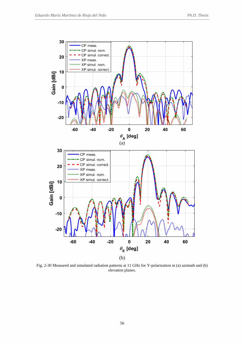
Eduardo María Martínez de Rioja del Nido Ph.D. Thesis
56
(a)
(b)
Fig. 2-30 Measured and simulated radiation patterns at 11 GHz for Y-polarization in (a) azimuth and (b) elevation planes.

Chapter 2. Design of reflectarrays for operation in dual polarization at two separate frequencies
57
(a)
(b)
Fig. 2-31 Measured and simulated radiation patterns at 13 GHz for X-polarization in (a) azimuth and (b) elevation planes.

Eduardo María Martínez de Rioja del Nido Ph.D. Thesis
58
(a)
(b)
Fig. 2-32 Measured and simulated radiation patterns at 13 GHz for Y-polarization in (a) azimuth and (b) elevation planes.

Chapter 2. Design of reflectarrays for operation in dual polarization at two separate frequencies
59
On the other hand, the comparison between simulated and measured radiation
patterns in Ka-band showed stronger disagreements than in Ku-band. It was checked
that the tolerance errors in the lengths and widths of the dipoles (an average increment
of 50μm) were not large enough to justify the differences. The bonding film (CuClad
6250, with εr = 2.32 and tanδ = 0.0013), which had been originally neglected in the
design of the antenna because of its small thickness (38 μm), was also considered in the
simulations by the inclusion of a new dielectric layer between layers A and B. As a
result, slight differences were detected in the radiation patterns, but they were not
sufficient to justify the difference between measured and simulated gain in Ka-band.
Afterwards, the dielectric constant and loss tangent of both substrates were measured
by using the technique described in [105]. The results showed that the dielectric
constant in Ka-band is always larger than the nominal values provided by the
manufacturer at 10 GHz. For AD255C, εrA = 2.7 was measured, instead of εrA = 2.55,
and for Diclad 880B, εrB = 2.3 was measured, instead of εrB = 2.17, being in both cases
around 6% higher than nominal values (1% tolerance is specified by the manufacturer at
10 GHz). The measured loss tangent is also larger than the nominal values: tanδ close to
0.005 was measured for both substrates, instead of tanδ = 0.0009. Therefore, additional
simulations were carried out by taking into account the measured values of permittivity
and loss tangent of layers A and B. As a consequence, the corrected radiation patterns in
Ka-band showed a better correspondence with experimental results (as will be shown
later, see Fig. 2-34), while the patterns in Ku-band presented a slight reduction in gain
(see Fig. 2-27 to Fig. 2-32 for the simulated patterns in Ku-band with the corrected
values of εr and tanδ).
The amplitude and phase response of the reflectarray cell was also analyzed
considering the corrected values of εr and tanδ, and the results for X-polarization are
presented in Fig. 2-33, superimposed to the curves obtained with the nominal values of
εr and tanδ that were shown in Fig. 2-16. As can be seen, the worst effects occur in Ka-
band, where the losses can be several times higher than originally expected. Moreover,
significant phase errors appear in those elements whose upper central dipoles present
length values larger than 5.5 mm (for example, these errors can be up to 80° at 20 GHz
in some cells of the reflectarray), being responsible for the deterioration of the antenna
radiation patterns.

Eduardo María Martínez de Rioja del Nido Ph.D. Thesis
60
(a)
(b)
Fig. 2-33 Magnitude and phase of the cell reflection coefficient, considering X-polarization and θi = 20º incidence: (a) at Ku-band, (b) at Ka-band.

Chapter 2. Design of reflectarrays for operation in dual polarization at two separate frequencies
61
Finally, it has been found that there are a few cells near the edge of the reflectarray,
for which the first higher order Floquet mode starts propagating at the higher
frequencies, which is the condition for grating lobe appearance. The analysis tool has
been modified to take into account the contribution of higher order Floquet harmonics
in the radiated field and the antenna has been analyzed again.
A slightly better agreement between simulations and measurements was found after
inclusion of higher order Floquet modes; however, the main source of discrepancies
between the original simulations and measurements is not the excitation of grating
lobes, but the difference between nominal and measured values of εr and tanδ in the
materials, as can be checked in Fig. 2-34. This figure shows the comparison of the
experimental and numerical radiation patterns for X-polarization at 19.5 GHz (central
design frequency in Ka-band), considering the effect of all the aforementioned factors in
the simulations: the correction performed in the values of εr and tanδ, the inclusion of
higher order Floquet modes and the sum of the two previous factors. As can be seen, the
differences between the patterns in green line (corrected values of εr and tanδ) and red
line (corrected values of εr and tanδ and higher order Floquet modes) are very small,
providing a reasonably good agreement with the measured patterns at 19.5 GHz.
The bad initial estimation of the dielectric constant of the substrate layers shifted the
antenna operation in the upper band to lower frequencies (from 19-20 GHz to around
18.5-19.5 GHz), while the higher measured loss tangent of the substrate layers also had
an effect on reducing the expected gain of the antenna, especially in Ka-band. The
simulated corrected patterns in Ka-band for X and Y polarizations, considering both the
measured values of εr and tanδ and the effect of higher order Floquet modes, are shown
in Fig. 2-34 and Fig. 2-35 for operation at 19.5 GHz, and in Fig. 2-36 and Fig. 2-37 for
operation at 19 GHz. As can be seen, a gain of 27.6 and 26.3 dBi is attained at 19 GHz
for the beams in X and Y polarizations, respectively, which is around 3 dB lower than
the originally expected, according to the simulations performed with the nominal values
of εr and tanδ of the materials. Due to the shift in the frequency response, the patterns
present further deterioration at 19.5 GHz, where the measured gain is about 4 dB lower
than the expected for X-polarization and 6 dB lower for Y-polarization. The inclusion of
the aforementioned correction factors in the simulations contributes to obtain a better
agreement with the measurements, causing a reduction in gain and an increase of side
lobes, as can be observed in the patterns.

Eduardo María Martínez de Rioja del Nido Ph.D. Thesis
62
(a)
(b)
Fig. 2-34 Measured and simulated radiation patterns at 19.5 GHz for X-polarization in (a) azimuth and (b) elevation planes.

Chapter 2. Design of reflectarrays for operation in dual polarization at two separate frequencies
63
(a)
(b)
Fig. 2-35 Measured and simulated radiation patterns at 19.5 GHz for Y-polarization in (a) azimuth and (b) elevation planes.
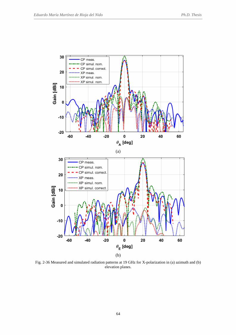
Eduardo María Martínez de Rioja del Nido Ph.D. Thesis
64
(a)
(b)
Fig. 2-36 Measured and simulated radiation patterns at 19 GHz for X-polarization in (a) azimuth and (b) elevation planes.

Chapter 2. Design of reflectarrays for operation in dual polarization at two separate frequencies
65
(a)
(b)
Fig. 2-37 Measured and simulated radiation patterns at 19 GHz for Y-polarization in (a) azimuth and (b) elevation planes.

Eduardo María Martínez de Rioja del Nido Ph.D. Thesis
66
Figure 2-38 shows the evolution of gain with frequency in each polarization for both
measurements and simulations, considering first the nominal values of εr and tanδ of the
two dielectric materials, and then, the corrected values. The radiation patterns were also
measured at 18 GHz in order to obtain a more complete characterization of the antenna
operation in the upper band. As can be seen, there is a shift in the frequency response in
Ka-band (the maximum gain is measured at 19 GHz instead of at 19.5 GHz), as a result
of the increased value of the measured dielectric constant. It can be observed that the
manufactured demonstrator is wideband in the lower band (roughly 20% bandwidth for
a gain variation smaller than 2 dB) and narrowband in the upper band (around 5%
bandwidth for a gain variation smaller than 2 dB).
(a)
(b)
Fig. 2-38 Measured vs simulated gain graphs in Ku and Ka bands: (a) for X-polarization, (b) for Y-polarization.

Chapter 2. Design of reflectarrays for operation in dual polarization at two separate frequencies
67
The resulting radiation efficiency for the fabricated antenna, calculated as the ratio
between the measured (or simulated) gain and the maximum directivity at each
frequency, varies between 34% and 43% in Ku-band (between 47% and 56% for the
simulations performed with nominal values), and is very low in Ka-band (the highest
value is 19% at 19 GHz). The other parameters of the antenna radiation patterns (side-
lobe level, SLL, and cross-polar discrimination, XPD) are summarized in Table 2-1 for
both simulations and measurements. The radiation patters and antenna gain should be
improved by using the real properties of the materials at the operation frequencies
(extracted from measurements) in the design process.
2.3.5 Conclusions
A reflectarray antenna capable of operating independently in the transmit frequencies
from the satellite in Ku-band (11-13 GHz) and Ka-band (19-20 GHz) has been proposed
and demonstrated. The reflectarray cell is composed of two orthogonally-arranged sets
of coupled parallel dipoles, which are distributed in a two-level configuration. A 25-cm
reflectarray prototype has been designed, manufactured and tested. The demonstrator
produces a collimated beam in dual polarization which radiates in the direction θb = 20º.
The results of the measurements show a quite good agreement with the simulations in
TABLE 2-1
COMPARISON OF ANTENNA PARAMETERS FOR THE KU/KA-BAND DEMONSTRATOR
Freq. (GHz)
SLL meas. (dB)
SLL corrected
(dB)
SLL nominal
(dB)
XPD meas. (dB)
XPD corrected
(dB)
XPD nominal
(dB)
Pol. X
11 13.40 13.71 13.60 21.48 22.31 24.62 12 13.65 17.75 16.51 23.82 22.07 24.79 13 14.15 17.18 18.12 24.03 22.19 26.73 19 16.50 16.34 17.58 21.66 21.36 24.51
19.5 8.47 10.47 15.40 26.18 14.92 19.54 20 2.41 5.34 10.63 18.78 14.43 15.53
Pol. Y
11 16.02 14.53 13.92 28.85 27.87 27.45 12 15.59 16.84 19.23 24.25 25.52 24.31 13 12.90 17.42 18.59 23.47 25.82 25.58 19 12.03 17.76 14.55 18.67 21.12 22.40
19.5 7.48 7.71 20.25 18.98 16.54 19.49 20 0.12 0.39 10.55 14.02 11.24 18.59

Eduardo María Martínez de Rioja del Nido Ph.D. Thesis
68
Ku-band, and some discrepancies at Ka-band mainly due to a variation in the electrical
properties of the materials (εr and tanδ), which produces a more severe impact at higher
frequencies. To avoid this problem, the materials should be accurately characterized by
measuring the dielectric constant and loss tangent at the operation frequencies, and
using then these values in the design of the antenna.
The dual-frequency reflectarray demonstrator is a proof-of-concept to show that the
proposed reflectarray can operate independently in two frequencies (Ku and Ka bands)
and two polarizations with separate feeds. This concept can be applied to transmit
antennas in Telecom satellite systems to reuse the same aperture for the generation of a
prescribed contoured beam in Ku-band and multiple spots in Ka-band with different
feed chains for each mission, which would result in significant savings in the cost,
volume and weight of the antenna farm.
2.4 Design of dual polarized reflectarrays to operate at transmit and
receive frequencies in Ka-band
As explained in Chapter 1, Ka-band currently represents the main alternative for
satellite systems to satisfy the growing demand for capacity. Modern satellite antennas
in Ka-band are required to generate a large number of high-gain overlapping spot
beams, with a very small separation between adjacent spots [82]. This factor, combined
with the deployment of frequency and polarization reuse schemes, leads to an increase
in the users’ data rates and the overall capacity of the network, enabling the provision of
high speed broadband services in Ka-band. From the users’ side, conventional reflectors
[106] and phased arrays [107] have been proposed for transmit and receive terminal
antennas; however, the different frequencies for uplink (30 GHz) and downlink (20
GHz) lead to a more complex antenna design.
Reflectarray antennas are able to generate independent beams in each polarization,
provide high values of gain and radiation efficiency, and operate simultaneously at
different frequencies. These capabilities can be of particular interest for the design of
both terminal and satellite antennas in Ka-band, but first, it requires to count on
appropriate reflectarray cells that will provide an independent control of the phase at
each frequency band (Tx and Rx) and/or polarization. For this purpose, the cell
configuration proposed in the previous sections has been adapted to allow independent

Chapter 2. Design of reflectarrays for operation in dual polarization at two separate frequencies
69
operation in dual-linear polarization at Tx and Rx frequencies in Ka-band. Afterwards,
the element has been used to design first a 20-cm reflectarray VSAT (Very Small
Aperture Terminal) antenna to generate a focused beam in dual polarization (linear or
circular) at 19.7 GHz and at 29.5 GHz, and then, a 1.6-m satellite antenna to produce
two closely spaced beams in orthogonal linear polarizations at both Tx and Rx
frequencies in Ka-band.
2.4.1 Design of the reflectarray cell
The unit-cell presents the same characteristics than the one used in the previous
section. It consists of two orthogonal sets of five parallel dipoles printed on a dielectric
layer, and two additional sets of three parallel dipoles stacked above the first sets and
printed on the top of a second dielectric sheet (see Fig. 2-39). The period, PX = PY = 6.5
mm, is chosen as 2·λ/3 at the higher design frequency (29.5 GHz) to avoid the
appearance of grating lobes up to 30º incidence. Both dielectric layers have been
implemented by Diclad 880 sheets; their electrical properties are εrA = εrB = 2.17, tanδA
= tanδB = 0.0009, and their thickness is hA = 1.5 mm, hB = 1 mm.
Fig. 2-39 View of the reflectarray periodic structure, including four unit-cells for X polarization and one
unit-cell for Y polarization.
The geometrical parameters of the cell have been fixed after a careful parametric
study, in order to provide a smooth variation in the phase response in a range larger than
360º in both frequency bands (19.2-20.2 GHz and 29-30 GHz). The dipole width is set
to 0.25 mm, separations between laterally coupled dipoles are SXA = SYA = 0.5 mm, SXB
= SYB = 1 mm, and relative sizes of lateral dipoles are lA1 = 0.65·lA3, lA2 = 0.8· lA3, lA4 =
0.65·lA6, lA5 = 0.8·lA6 (where lA3 and lA6 correspond to the lengths of the central dipoles

Eduardo María Martínez de Rioja del Nido Ph.D. Thesis
70
on the lower layer), lB1 = 0.8· lB2, lB3 = 0.8·lB4 (where lB2 and lB4 correspond to the central
dipoles’ lengths on the upper layer). The amplitude and phase curves of the cell
reflection coefficient as a function of the dipole lengths are shown in Fig. 2-40 at the
central and extreme frequencies of each band, considering X-polarization and normal
incidence conditions.
(a)
(b)
Fig. 2-40 Phase and amplitude of the cell reflection coefficient for X-polarization under normal incidence: (a) at Tx band and (b) at Rx band.

Chapter 2. Design of reflectarrays for operation in dual polarization at two separate frequencies
71
Furthermore, the phase curves of the cell reflection coefficient exhibit a robust
response against variations in the angle of incidence (see Fig. 2-41), which have almost
no effect at the lower frequency band, while producing slight variations in the phase-
shift at the higher frequencies.
(a)
(b)
Fig. 2-41 Variation with the angle of incidence in the phase of the cell reflection coefficient for X-polarization: (a) at 19.7 GHz, and (b) at 29.5 GHz.
A practically independent phase control based on the lengths of upper and lower
dipoles can be observed in Fig. 2-42, which shows the variation in the phase of the cell
reflection coefficient at 19.7 and 29.5 GHz, for X-polarization under normal incidence
(note that the same response is obtained for Y-polarization, although it is not shown
here). As can be seen, the upper dipoles will not disturb the phase response at 19.7 GHz,
as they are shorter than the ones in the bottom layer, while lower dipoles will have a
certain influence on the phase at 29.5 GHz. Therefore, the dipole lengths can be
obtained separately for each band, as in the case of the Ku/K-band reflectarray designed
in the previous section: first, the dipoles on the bottom layer are adjusted to provide the
required phase-shift at 19.7 GHz, and then those on the top layer are adjusted to provide
the required phase at 29.5 GHz.

Eduardo María Martínez de Rioja del Nido Ph.D. Thesis
72
(a) (b)
Fig. 2-42 Phase (in degrees) of the cell reflection coefficient with respect to the lengths of the dipoles in both layers, considering X-polarization (a) at 19.7 GHz and (b) at 29.5 GHz.
2.4.2 Design of a Tx/Rx terminal SatCom antenna in Ka-band
A 20-cm sided reflectarray, consisting of 900 elements arranged in a 30 x 30 grid,
has been designed to generate a focused beam in the direction θb = 13°, φb = 0° for the
two orthogonal polarizations (with the electric field in the direction of the dipoles) at
19.7 and 29.5 GHz. Since the antenna is designed to provide the same radiation pattern
for the two orthogonal components of the incident field, it will operate in dual-circular
polarization when it is illuminated by a dual-circularly polarized feed-horn.
The phase center of the feed is placed at coordinates (xF, yF, xF) = (-40, 0, 195) mm
relative to the geometrical center of the reflectarray (origin of the coordinates system).
The electromagnetic field radiated by the feed-horn is modeled using a cosq(θ)
distribution, with q = 10.5 for 20 GHz band and q = 10.7 for 30 GHz band.
The SD-MoM electromagnetic code has been employed to adjust the lengths of the
dipoles in both layers, in order to provide the phase-shift distributions shown in Fig.
2-43 for both polarizations, at 19.7 GHz and 29.5 GHz, considering the real angles of
incidence on each reflectarray element (see Fig. 2-44). Then, the dimensions of all
dipoles are optimized element-by-element to simultaneously match the phases at the
central and extreme frequencies in the lower (19.2-20.2 GHz) and higher (29-30 GHz)
frequency bands, following a procedure similar to the one described in section 2.3.2 for
the design of the Ku/Ka-band reflectarray demonstrator.

Chapter 2. Design of reflectarrays for operation in dual polarization at two separate frequencies
73
(a) (b)
Fig. 2-43 Required phase-shift distributions (in degrees) to be implemented on the reflectarray for both polarizations: (a) at 19.7 GHz, (b) at 29.5 GHz.
(a) (b)
Fig. 2-44 Angles of incidence (in degrees) from the feed on each reflectarray cell: (a) theta, (b) phi.
2.4.2.1 Results of the simulations
The simulated radiation patterns in gain (dBi) have been obtained from the tangential
electric and magnetic reflected fields at each reflectarray cell, using the aforementioned
SD-MoM software. Fig. 2-45 shows the simulated radiation patterns of the reflectarray
VSAT antenna at 19.7 GHz in the elevation and azimuth orthogonal planes, including
the co- and cross-polar components of each linear polarization. A gain of 31.4 dBi and
31 dBi is achieved for the beams in X and Y polarizations, respectively, with side-lobe
levels (SLL) close to -22 dB with respect to the co-polar maximum. The cross-polar
discrimination (XPD), measured within a 3-dB beamwidth (4.72º) of the main lobe, is
around 33 dB.

Eduardo María Martínez de Rioja del Nido Ph.D. Thesis
74
(a)
(b)
Fig. 2-45 Simulated radiation patterns in gain (dBi) at 19.7 GHz for X and Y polarizations: (a) xz-plane (elevation), (b) orthogonal plane in the direction of the beam (azimuth).
On the other hand, Fig. 2-46 shows the simulated radiation patterns of the
reflectarray VSAT antenna at the central design frequency in the higher band (29.5
GHz). In this case, a gain of 34.2 dBi and 33.8 dBi is achieved for the beams in X and Y
polarizations, respectively, with XPD around 31 dB and SLL close to -20 dB with
respect to the maximum. The 3-dB beamwidth is now 3.15º.

Chapter 2. Design of reflectarrays for operation in dual polarization at two separate frequencies
75
(a)
(b)
Fig. 2-46 Simulated radiation patterns in gain (dBi) at 29.5 GHz for X and Y polarizations: (a) xz-plane (elevation), (b) orthogonal plane in the direction of the beam (azimuth).
After the multi-frequency optimization, an 8% bandwidth can be achieved in the
lower frequency band with a gain variation of 1 dB for X-polarization and 1.5 dB for Y-
polarization. The simulated radiation patterns in the principal planes at the extreme
frequencies of this band, 18.9 GHz and 20.5 GHz, are shown in Fig. 2-47 and Fig. 2-48,
respectively. In the case of the higher frequency band, a 5% bandwidth can be achieved
with the same gain variation (1 dB for X-polarization and 1.5 dB for Y-polarization).
The simulated radiation patterns in the principal planes at the extreme frequencies, 28.8
GHz and 30.2 GHz, are presented in Fig. 2-49 and Fig. 2-50, respectively.

Eduardo María Martínez de Rioja del Nido Ph.D. Thesis
76
(a) (b)
Fig. 2-47 Simulated radiation patterns at 18.9 GHz for the VSAT reflectarray antenna, for X and Y polarizations: (a) xz-plane, (b) orthogonal plane in the direction of the beam (azimuth).
(a) (b)
Fig. 2-48 Simulated radiation patterns at 20.5 GHz for the VSAT reflectarray antenna, for X and Y polarizations: (a) xz-plane, (b) orthogonal plane in the direction of the beam (azimuth).
(a) (b)
Fig. 2-49 Simulated radiation patterns at 28.8 GHz for the VSAT reflectarray antenna, for X and Y polarizations: (a) xz-plane, (b) orthogonal plane in the direction of the beam (azimuth).

Chapter 2. Design of reflectarrays for operation in dual polarization at two separate frequencies
77
(a) (b)
Fig. 2-50 Simulated radiation patterns at 30.2 GHz for the VSAT reflectarray antenna, for X and Y polarizations: (a) in the azimuth plane, (b) in the elevation plane.
The antenna efficiency has been estimated at 67% in the lower band and 57% in
higher band, considering illumination, spillover and dielectric losses. These results
show the potential of reflectarrays for dual-frequency and dual-polarization operation as
a low-cost alternative for Ka-band terminal antennas.
2.4.3 Design of a Tx/Rx satellite antenna in Ka-band
A circular reflectarray antenna, consisting of 49,080 elements arranged in a 250 x
250 grid (162.5 cm diameter), has been designed to generate a focused beam in the
direction θb = 10°, φb = 0° for X-polarization and a closely spaced beam at θb = 10.5°, φb
= 0° for Y-polarization at 19.7 GHz and 29.5 GHz, which are transmit and receive
frequencies for multi-spot satellite antennas in Ka-band.
The reflectarray is illuminated by a corrugated feed-horn, whose phase center is
placed at coordinates (xF, yF, zF) = (-300, 0, 1000) mm with respect to the reflectarray
center. The field radiated by the horn is modeled using a cosq(θ) function, with q = 6 for
the Tx band and q = 8 for the Rx band. The edge illumination levels are close to -16 dB
at 19.7 GHz and -18 dB at 29.5 GHz.
The required phase-shift distributions to be introduced by the reflectarray elements in
each frequency (19.7 and 29.5 GHz) and polarization (X and Y) are shown in Fig. 2-51.
The lengths of the dipoles on both layers are adjusted by using the SD-MoM software
tool, which takes into account the real angles of incidence (θi, φi) on each reflectarray
cell (see Fig. 2-52) to calculate the amplitude and phase of the reflection coefficient,
considering the element in a periodic environment.

Eduardo María Martínez de Rioja del Nido Ph.D. Thesis
78
(a) (b)
(c) (d)
Fig. 2-51 Phase-shift distributions (in degrees) to be introduced by the reflectarray: at 19.7 GHz (a) in X-polarization and (b) in Y-polarization, and at 29.5 GHz (c) in X-polarization and (b) in Y-polarization.
(a) (b)
Fig. 2-52 Angles of incidence (in degrees) from the feed on each reflectarray cell: (a) theta, (b) phi.
In this case, the design of the reflectarray elements has been performed only at the
central frequencies of each band. First, the dipoles in the lower layer are adjusted to
match the required phases at 19.7 GHz, and then, the dipoles on the top layer are
adjusted to do the same with the phases at 29.5 GHz. The execution of a multi-

Chapter 2. Design of reflectarrays for operation in dual polarization at two separate frequencies
79
frequency optimization routine could improve the antenna performance within each
operating band by a fine tuning of the dipole lengths, but it would be a very time-
consuming process due to the extremely large number of elements (it would require
several days for optimizing the whole antenna). On the other hand, the design of the
dipoles at the central frequency of each band takes only a couple of hours.
2.4.3.1 Results of the simulations
The simulated radiation patterns of the 1.6-m reflectarray antenna in the elevation
and azimuth planes are shown in Fig. 2-53 (at 19.7 GHz) and Fig. 2-54 (at 29.5 GHz).
(a)
(b)
Fig. 2-53 Simulated radiation patterns in gain (dBi) at 19.7 GHz for X and Y polarizations: (a) xz-plane (elevation), (b) orthogonal plane in the direction of the beam (azimuth).

Eduardo María Martínez de Rioja del Nido Ph.D. Thesis
80
(a)
(b)
Fig. 2-54 Simulated radiation patterns in gain (dBi) at 29.5 GHz for X and Y polarizations: (a) xz-plane (elevation), (b) orthogonal plane in the direction of the beam (azimuth).
As can be seen, the proposed reflectarray is able to generate two closely spaced
beams (only 0.5º of spacing) in orthogonal polarizations both at Tx and Rx frequencies,
when the antenna is illuminated by a single feed operating in dual-linear polarization. A
gain of 48.3 dBi is attained at 19.7 GHz, and 50.7 dBi gain is reached at 29.5 GHz, with
low levels for cross-polar components (around 30 dB below the co-polar maximum).
The 3-dB beamwidth is between 0.6º and 0.7º, and SLL is close to -30 and -25 dB with
respect to the co-polar maximum at 19.7 and 29.5 GHz, respectively. Finally, the
radiation efficiency of the 1.6-m reflectarray can be estimated as 66% at the Tx band
and 48% at the Rx band, which are typical values for conventional reflectors.
Chapter 2. Design of reflectarrays for operation in dual polarization at two separate frequencies
81
2.4.4 Conclusions
These results show the potential of reflectarrays for working at transmit and receive
frequencies in Ka-band, with independent beam-shaping in each polarization and
frequency band. The dimensions of the reflectarray element used in sections 2.2 and 2.3,
based on two stacked layers with orthogonal sets of parallel dipoles, have been modified
to allow simultaneous phase adjustment in both linear polarizations at 19.7 and 29.5
GHz, providing a linear phase variation within a 360º range and a robust behaviour with
respect to variations in the angle of incidence.
The simulated radiation patterns are very promising for terminal SatCom antennas
and multi-spot satellite antennas that operate in Ka-band. The proposed 20-cm
reflectarray VSAT antenna is able to generate a focused beam in dual-polarization
(linear or circular) at both transmit and receive frequencies in Ka-band. The reduced
number of layers and the simplicity of the printed elements make it a low-cost
alternative to reflectors and phased arrays. On the other hand, the 1.6-m satellite
reflectarray antenna produces two adjacent beams (0.5º of spacing) in orthogonal linear
polarizations at both Tx and Rx bands, when the antenna is illuminated by a single dual-
polarized feed. In this case, the beams can also be generated in dual-circular
polarization if the orthogonal polarizations are discriminated by means of a sequential
rotation technique applied to the reflectarray elements, as proposed in [59].
2.5 Conclusions
In this chapter, a novel reflectarray cell has been proposed and demonstrated to
operate at two separate frequencies in dual polarization. The element consists of two
orthogonal sets of parallel dipoles, arranged in a two-layer configuration. Each set is
composed of five parallel dipoles on the lower layer, and three additional parallel
dipoles which are stacked above the previous ones and are printed on the top of a
second dielectric sheet. The geometrical parameters of the cell have been adjusted to
operate, first, in transmission in Ku and Ka bands (12 and 20 GHz), and then, in
transmission and reception in Ka-band (20 and 30 GHz), providing a smooth variation
in the phase of the co-polar reflection coefficient with respect to the dipoles’ lengths and
covering a range of phase greater than 360º at both design frequencies.

Eduardo María Martínez de Rioja del Nido Ph.D. Thesis
82
The phase-shift introduced in each linear polarization is controlled by the orthogonal
sets of dipoles, which are practically uncoupled. Moreover, the dipoles on the lower
layer will provide the required phases at the lower frequency, while the dipoles on the
upper layer will do the same with the phases at the higher frequency. This operating
principle is made possible as the lengths of the lower dipoles are larger than those of the
upper dipoles, providing an independent control of the phase at each design frequency.
This allows for performing separate design processes for each reflectarray layer: first,
the lengths of the lower dipoles are adjusted to match the phases at the lower frequency,
and then, the lengths of the upper dipoles are adjusted to introduce the required phase-
shift at the higher frequency, while correcting the effect of the bottom dipoles at the
same time.
The proposed element has been used to design several reflectarray antennas, first to
operate at Tx frequencies in Ku and Ka bands, and then at Tx and Rx frequencies in Ka
band. These designs show the capability of reflectarrays to generate independent beams
in each polarization at both frequency bands. Also, a 25-cm demonstrator that operates
in Ku (11-13 GHz) and Ka (19-20 GHz) bands in dual polarization (linear or circular)
has been designed, manufactured and tested in order to validate the concept. The results
of the measurements show a quite good agreement with the simulations in Ku-band, and
some discrepancies in Ka-band due to a variation in the electrical properties of the
dielectric sheets, which produces a more severe impact at higher frequencies. This
problem can be avoided by an accurate characterization of the materials, before
performing the design of the antenna.
The proposed concept can be applied to design a reflectarray antenna which is able to
fulfill independent requirements at each frequency and/or polarization (different
missions). For example, a contoured beam can be generated in Ku-band and multiple
spots can be obtained in Ka-band by properly designing the elements on each
reflectarray layer, considering different feed chains for each mission. The reuse of the
same aperture for both missions would result in significant savings in the costs, weight
and volume of the antenna farm, especially in the case of telecommunication satellites
which operate in Ku and Ka bands.

83
Chapter 3
Application of the bifocal technique to dual reflectarray configurations
3.1 Introduction
The bifocal technique has been considered for many years as one of the main
alternatives for the design of multiple beam and wide-angle beam scanning antennas.
The bifocal concept was introduced in the 1950s, concerning the design of two-surface
axially-symmetrical dielectric lenses which are able to collimate the rays from a point
source, placed at either of two conjugate off-axis locations, into a plane wave forming
an angle of ±θ0 with respect to the symmetry axis [108], [109]. In these conditions, the
bifocal design provides an improved performance for the off-axis beams (in terms of
gain, side-lobe levels and beam shaping) with respect to the equivalent single focused
case, at the cost of a slightly worse performance for the central beam.
On the basis of dielectric lenses, the bifocal technique was adapted to allow the
simultaneous design of dual reflector systems for two focal points [80], [81], so that two
feeds placed at the foci will produce two beams emerging at directions θ1 and θ2 by
properly shaping both reflectors. Note that at least two reflectors are required to have
enough degrees of freedom for the design. The appropriate shape of each reflector can
be obtained by means of a geometrical optics (GO) procedure, based on the application
of Snell’s law of reflection and the equal path-length condition, which involves the
interpolation of two sets of points (one set per reflector) and their associated normal
vectors. In the case of an axially-symmetrical configuration [80], a simple solution to
the 3D design problem can be obtained by rotation of a 2D bifocal design performed in
the offset plane (the antenna symmetry plane, which contains the foci and the beams).

Eduardo María Martínez de Rioja del Nido Ph.D. Thesis
84
This technique allows to design not only centered, but also offset configurations by
properly selecting specific parts of the revolution surfaces that are obtained [110].
The extension of the 2D GO procedure to 3D for dual offset configurations without
axial symmetry was carried out by Rappaport [81]. However, the design of these offset
configurations (such as Cassegrain or Gregorian) has proved to be very challenging.
Particularly, it requires to define a set of even-degree polynomials that will determine
the shape of each reflector along the antenna cross section. The difficulty in obtaining
smooth profiles for both reflectors has led to new design approaches, as the one based
on the optimization of the effective area of the bifocal antenna [111]. This method tries
to achieve the most efficient illumination of the main reflector by illuminating only a
half of the sub-reflector for each of the two beams generated from the foci.
Thanks to their large field of view, several bifocal dual reflectors have been proposed
in the last years for wide-angle beam scanning applications, such as THz imaging [112],
[113] and satellite ground stations [114]. Moreover, a few papers have been reported on
the bifocal design of dual reflectarray antennas (DRA) [17], [115], [116], where the
main issue relies on the calculation of the required phase-shift distributions for each
reflectarray. The initial works [17], [115] focused on the design of small-size DRAs for
automotive radar applications (the main reflectarray diameter is lower than 30 cm),
considering centered and rotationally-symmetrical geometries where blockage from the
sub-reflectarray is avoided by using a gridded sub-reflector and a 90º twist of
polarization on the main reflectarray. The limitation of this configuration is that the
antenna can only operate in single linear-polarization. The application of the bifocal
technique to offset DRA configurations of larger size was first studied in [116], where
the phase distributions on both reflectarrays were approximated from an equivalent
offset bifocal dual reflector obtained by applying Rappaport’s technique [81], but the
results were not satisfactory.
In this chapter, a novel bifocal procedure is proposed for the design of offset dual
reflectarray configurations of large size, starting from an axially-symmetrical geometry
with parallel reflectarrays in which a 2D GO algorithm is applied, followed by the
rotation of the resulting phase curves around the symmetry axis. An offset DRA system
can be formed by selected parts of the revolution surfaces, and then, both reflectarrays
can be tilted to obtain smoother phase distributions. The proposed technique has been
applied to the design of multi-beam satellite antennas in Ka-band, in order to provide a

Chapter 3. Application of the bifocal technique to dual reflectarray configurations
85
reduced beam spacing and an improved performance for the extreme beams with respect
to the equivalent single-focus antenna.
3.2 Bifocal design procedure for dual reflectarray antennas
The simplest way of implementing the bifocal concept on a dual reflectarray antenna
considers the design of an axially-symmetrical configuration (see Fig. 3-1), following a
similar approach to the one presented in [80] for the design of dual reflectors.
Originally, both reflectarrays are placed in parallel planes, in order to subsequently
exploit the symmetry of the configuration by rotation of a 2D bifocal design.
Fig. 3-1 Geometry and main parameters of the bifocal dual reflectarray antenna with parallel
reflectarrays, including the first step of the bifocal ray-tracing routine in the xz-plane.
The initial parameters that characterize the geometry of the DRA system and must be
fixed before starting the bifocal procedure are: distance between foci (d), distance
between the foci and the sub-reflectarray (L1), distance between the two reflectarrays
(L2), and directions of the radiated beams (θb1 and θb2). As can be observed in Fig. 3-1, a
symmetrical arrangement of the focal points along the x-axis is considered, so that their
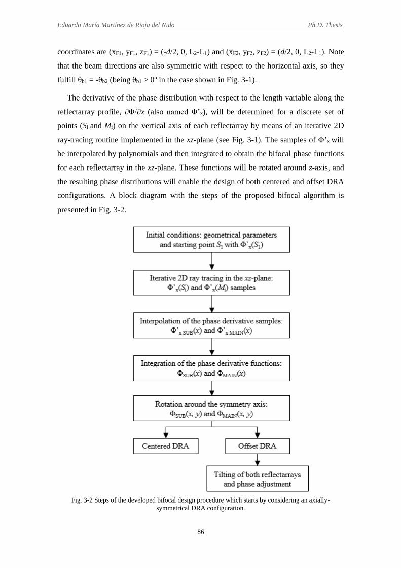
Eduardo María Martínez de Rioja del Nido Ph.D. Thesis
86
coordinates are (xF1, yF1, zF1) = (-d/2, 0, L2-L1) and (xF2, yF2, zF2) = (d/2, 0, L2-L1). Note
that the beam directions are also symmetric with respect to the horizontal axis, so they
fulfill θb1 = -θb2 (being θb1 > 0º in the case shown in Fig. 3-1).
The derivative of the phase distribution with respect to the length variable along the
reflectarray profile, ∂Φ/∂x (also named Φ’x), will be determined for a discrete set of
points (Si and Mi) on the vertical axis of each reflectarray by means of an iterative 2D
ray-tracing routine implemented in the xz-plane (see Fig. 3-1). The samples of Φ’x will
be interpolated by polynomials and then integrated to obtain the bifocal phase functions
for each reflectarray in the xz-plane. These functions will be rotated around z-axis, and
the resulting phase distributions will enable the design of both centered and offset DRA
configurations. A block diagram with the steps of the proposed bifocal algorithm is
presented in Fig. 3-2.
Fig. 3-2 Steps of the developed bifocal design procedure which starts by considering an axially-
symmetrical DRA configuration.

Chapter 3. Application of the bifocal technique to dual reflectarray configurations
87
3.2.1 Iterative ray-tracing routine in 2D
The 2D ray-tracing routine maintains the same philosophy than in the bifocal design
of dual reflectors, alternating transmitted and received rays in the same way that is
described in [80]. However, a specific phase condition has to be considered on each
reflectarray cell, instead of applying the Snell’s law of reflection. As shown in [17], the
following expression relates the phase derivative on the reflectarray with the angles of
the incident (θi) and reflected (θo) rays:
Φ′𝑥 =𝜕Φ
𝜕𝑥 =
2𝜋
𝜆· (sin 𝜃𝑖 − sin 𝜃𝑜) (3-1)
The first iteration of the ray-tracing algorithm requires an starting point on the sub-
reflectarray axis, S1 = (xS1, 0, L2), and the value of the phase derivative at that point,
Φ’x(S1). Note that the value of Φ’x(S1) cannot be arbitrarily set: for every point on the
sub-reflectarray we can obtain the incidence angle θi1 from focus F1 (being θi1 > 0 in the
case that xS1 > -d/2), and then, eq. (3-1) will fix an upper and a lower limit for the phase
derivative at S1, as the reflection angles must be between -90º and 90º:
2𝜋
𝜆· (sin 𝜃𝑖1 − 1) <
𝜕Φ
𝜕𝑥 <
2𝜋
𝜆· (sin 𝜃𝑖1 + 1) (3-2)
In the case of Fig. 3-1, where a symmetrical arrangement of the foci and the radiated
beams with respect to z-axis is considered, it can be deduced that the phase distributions
of both reflectarrays in the xz-plane will present even symmetry with respect to z-axis.
The phase will have a maximum or a minimum at x = 0, which means that the value of
Φ’x at x = 0 will be equal to zero. Hence, the point S1 = (0, 0, L2) on the sub-reflectarray
with Φ’x(S1) = 0 can be selected to start the first iteration of the algorithm.
The bifocal ray-tracing algorithm works in the way that follows. First, a transmitted
ray from focus F1 that impinges on S1 is used to obtain a new point on the main
reflectarray, M1 = (xM1, 0, 0), and its associated phase derivative, Φ’x(M1), by applying
(3-1) first on the sub-reflectarray (where the incidence angle and the phase derivative
are known), and then, on the main reflectarray (where both the incidence and output
angles are known), see Fig. 3-1. Similarly, if we consider a received ray in the direction
θb2 that impinges on M1, a new point on the sub-reflectarray, S2 = (xS2, 0, L2), and the
value of its phase derivative, Φ’x(S2), are obtained by enforcing the ray to reach focus
F2, following the same procedure than before. Then, a transmitted ray from F1 that

Eduardo María Martínez de Rioja del Nido Ph.D. Thesis
88
impinges on S2 can be used to start a new iteration of the process. After N iterations, two
sets of points are originated in the xz-plane, one for the main reflectarray and one for the
sub-reflectarray, with their corresponding phase derivatives. A flow chart with the steps
of the 2D bifocal ray-tracing algorithm is shown in Fig. 3-3.
Fig. 3-3 Flow chart with the steps of the iterative 2D ray-tracing procedure.
Starting point: S1 and Φ’x(S1)
A transmitted ray from F1 impinges on Si and is
reflected towards the main reflectarray:
The ray impinges on Mi and is reflected with an
angle θb1, so that the phase derivative Φ’x(M1) is:
The ray impinges on Si+1 and is reflected towards F2,
so that the phase derivative Φ’x(Si+1) is:
sin 𝜃𝑟𝑒𝑓𝑙 = sin 𝜃𝑖𝑛𝑐1 −𝜆
2𝜋· Φ𝑥
′ (𝑆𝑖)
Φ𝑥′ (𝑀𝑖) =
2𝜋
𝜆· sin 𝜃𝑟𝑒𝑓𝑙 − sin 𝜃𝑏1
A received ray in the direction θb2 impinges on Mi
and is reflected towards the sub-reflectarray:
Φ𝑥′ (𝑆𝑖+1) =
2𝜋
𝜆· sin 𝜃𝑖𝑛𝑐2 − sin 𝜃𝑟𝑒𝑓𝑙
sin 𝜃𝑟𝑒𝑓𝑙 = sin 𝜃𝑏2 +𝜆
2𝜋· Φ𝑥
′ (𝑀𝑖)
New point Mi
New point Si+1
i = 1
i = i + 1
i ≤ N
A set of phase derivative samples is obtained for each
reflectarray: Φ’x(Si) and Φ’x(Mi)
no
yes

Chapter 3. Application of the bifocal technique to dual reflectarray configurations
89
This procedure can be applied in a similar way starting at the point M1’= (0, 0, 0) on
the main reflectarray axis (see Fig. 3-4), also with Φ’x(M1) = 0 due to the symmetry of
the antenna configuration. A received ray in the direction θb2 that impinges on M1’ will
provide a new point on the sub-reflectarray, S1’, and the value of its phase derivative,
Φ’x(S1’), by applying (3-1) on both reflectarrays and enforcing the ray to reach focus F2.
Then, a transmitted ray from F1 that impinges on S1’ can be used to obtain a second
point on the main reflectarray, M2’, and its associated phase derivative, Φ’x(M2’), thus
continuing with the previously described ray-tracing technique. In the end, this
procedure allows to double the number of points that characterize each reflectarray,
which will improve the accuracy in the calculation of the bifocal phase curves.
Fig. 3-4 Second execution of the iterative ray-tracing routine, starting on the main reflectarray.
3.2.2 Integration of the phase derivatives
The phase derivative samples obtained in the xz-plane are interpolated by means of
even polynomials depending on x variable, providing two functions named Φ’x SUB(x)
and Φ’x MAIN(x). Then, these functions are integrated to obtain the required bifocal
phases on each reflectarray, ΦSUB(x) and ΦMAIN(x). For simplicity, the integration
constant is assumed to be zero, although a different value can be considered in order to

Eduardo María Martínez de Rioja del Nido Ph.D. Thesis
90
adjust the phase distributions on both reflectarrays (note that the addition of a constant
to the phase distributions will have no effect on the antenna radiation patterns). An
example of the results that can be achieved after performing two independent executions
of the ray-tracing routine, one starting at S1 = (0, 0, L2) and the other at M1 = (0, 0, 0), is
shown in Fig. 3-5 and Fig. 3-6, for a DRA system designed at 20 GHz with the
following parameters: d = 20 cm, L1 = 1 m, L2 = 1.5 m, θb1 = 1.5º and θb2 = -1.5º.
(a) (b) Fig. 3-5 Interpolation of the phase derivative samples on the: (a) sub-reflectarray, (b) main reflectarray.
(a) (b)
Fig. 3-6 Phase curves obtained after the integration of the phase derivatives on the: (a) sub-reflectarray, (b) main reflectarray.
3.2.3 Rotation of the phase curves
The previous phase distributions only allow to collimate the beams in the xz-plane.
Thus, the results of the bifocal synthesis have to be extended from 2D to 3D, so as to
obtain a surface phase distribution for each reflectarray. In this case, taking advantage
of the symmetry of the antenna configuration with respect to z-axis and the placement of
the two reflectarrays in parallel planes, both phase curves can be rotated in the xy-plane

Chapter 3. Application of the bifocal technique to dual reflectarray configurations
91
around z-axis. The rotation implies a change of variable in the phase polynomials
obtained in the xz-plane:
𝑥 → √𝑥2 + 𝑦2 (3-3)
This process is analogous to the one performed with reflectors [112], and results in a
focal ring which contains F1 and F2. This fact improves the antenna performance for the
generation of multiple beams, as it extends the focal region out of the xz-plane. The
resulting phase distributions allow to design either centered or offset DRA
configurations just by selecting specific portions of the phase distributions of both
reflectarrays, as can be seen in Fig. 3-7. The offset configuration has the advantage of
reducing blockage from the sub-reflectarray, and will be the selected option for the
upcoming designs. The appropriate size of each reflectarray for obtaining a proper
illumination (which contributes to achieve good radiation efficiency) can be estimated
based on the separation of the points obtained in the xz-plane for both reflectarrays after
the ray-tracing. Note that the illumination on each reflectarray will be concentrated in
the regions where the points are very close one to each other, and therefore these
regions should be included in the antenna to avoid a high spillover. On the other hand,
the regions with few and disperse points will have a low illumination and can be
removed. The size of the main reflectarray, as well as the illumination level at the edges,
will determine the gain of the bifocal antenna.
Fig. 3-7 Schematic representation of the DRA system obtained after rotation.

Eduardo María Martínez de Rioja del Nido Ph.D. Thesis
92
The main drawback for the design of offset configurations with parallel reflectarrays
is that the resulting phase-shift distributions present a high number of 360º cycles,
especially in the case of the main reflectarray. This reduces the potential bandwidth of
the reflectarrays and makes difficult their practical implementation in a real antenna, as
the local periodicity approach, commonly used in the electromagnetic analysis of the
reflectarray, assumes a smooth variation in phase between adjacent cells. As an
example, Fig. 3-8 shows the results obtained for the phase distributions in the previous
DRA design performed at 20 GHz with parallel reflectarrays, whose bifocal phase
curves were shown in Fig. 3-6. An offset configuration has been selected to minimize
blockage: the points from x = 0.2 m to x = 0.8 m have been chosen for constituting the
sub-reflectarray (0.6 m diameter), and the associated points from x = 0.8 m to x = 2.6 m,
for the main reflectarray (1.8 m diameter). The cell period in both reflectarrays is 10
mm. The large size of the main reflectarray and the initial conditions of the bifocal
synthesis (parallel reflectarrays) are responsible for the high number of 360º cycles that
can be seen in Fig. 3-8.
(a) (b) Fig. 3-8 Bifocal phase distributions (in degrees) for: (a) the sub-reflectarray and (b) the main reflectarray.
3.2.4 Reflectarray tilting and correction of the phase distributions
The use of an axially-symmetrical geometry with parallel reflectarrays has been
considered due to the possibility of applying rotation to the bifocal phase curves in the
xz-plane, which provides a simple 3D solution for the design of the bifocal DRA.
However, a more natural configuration would present both reflectarrays tilted a certain
angle with respect to x-axis, trying to assimilate as much as possible to an equivalent
Cassegrain reflector. Consequently, the geometry of the DRA is modified in the way

Chapter 3. Application of the bifocal technique to dual reflectarray configurations
93
that is shown in Fig. 3-9, where θS and θM are the tilt angles of the sub- and main
reflectarrays, respectively.
(a) (b)
Fig. 3-9 Geometry of the dual reflectarray antenna: (a) initially, (b) after tilting both reflectarrays.
Note that both reflectarrays are tilted about their geometrical centers and that the foci
are rotated together with the sub-reflectarray, in order to maintain the same angles of
incidence on the sub-reflectarray. Furthermore, the beams are pointed in the same
directions with respect to z-axis (in the absolute reference system) than in the original
design, although the relative directions with respect to the normal vector to the main
reflectarray surface (�̂�M) are now θM + θb1 and θM + θb2.
The values of the angles θS and θM that will provide the smoothest variation in the
final phase distributions of both reflectarrays can be estimated from the unwrapped
bifocal phase curves obtained in the xz-plane, or phase delay not limited to 360º (called
Φd), as follows:
𝜃𝑆 ≈ sin−1 [ 𝑚𝑎𝑥 (∆Φ𝑆
𝑑 ) · 𝜆/2𝜋
𝐷𝑆/2] (3-4)
𝜃𝑀 ≈ 0.5 · sin−1 [ 𝑚𝑎𝑥 (∆Φ𝑀
𝑑 ) · 𝜆/2𝜋
𝐷𝑀/2] (3-5)
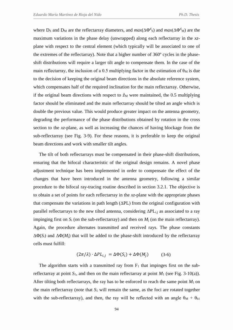
Eduardo María Martínez de Rioja del Nido Ph.D. Thesis
94
where DS and DM are the reflectarray diameters, and max(ΔΦdS) and max(ΔΦd
M) are the
maximum variations in the phase delay (unwrapped) along each reflectarray in the xz-
plane with respect to the central element (which typically will be associated to one of
the extremes of the reflectarray). Note that a higher number of 360º cycles in the phase-
shift distributions will require a larger tilt angle to compensate them. In the case of the
main reflectarray, the inclusion of a 0.5 multiplying factor in the estimation of θM is due
to the decision of keeping the original beam directions in the absolute reference system,
which compensates half of the required inclination for the main reflectarray. Otherwise,
if the original beam directions with respect to �̂�M were maintained, the 0.5 multiplying
factor should be eliminated and the main reflectarray should be tilted an angle which is
double the previous value. This would produce greater impact on the antenna geometry,
degrading the performance of the phase distributions obtained by rotation in the cross
section to the xz-plane, as well as increasing the chances of having blockage from the
sub-reflectarray (see Fig. 3-9). For these reasons, it is preferable to keep the original
beam directions and work with smaller tilt angles.
The tilt of both reflectarrays must be compensated in their phase-shift distributions,
ensuring that the bifocal characteristic of the original design remains. A novel phase
adjustment technique has been implemented in order to compensate the effect of the
changes that have been introduced in the antenna geometry, following a similar
procedure to the bifocal ray-tracing routine described in section 3.2.1. The objective is
to obtain a set of points for each reflectarray in the xz-plane with the appropriate phases
that compensate the variations in path length (ΔPL) from the original configuration with
parallel reflectarrays to the new tilted antenna, considering ΔPLi,j as associated to a ray
impinging first on Si (on the sub-reflectarray) and then on Mj (on the main reflectarray).
Again, the procedure alternates transmitted and received rays. The phase constants
ΔΦ(Si) and ΔΦ(Mj) that will be added to the phase-shift introduced by the reflectarray
cells must fulfill:
(2𝜋/𝜆) · ∆𝑃𝐿𝑖,𝑗 = ∆Φ(𝑆𝑖) + ∆Φ(𝑀𝑗) (3-6)
The algorithm starts with a transmitted ray from F1 that impinges first on the sub-
reflectarray at point S1, and then on the main reflectarray at point M1 (see Fig. 3-10(a)).
After tilting both reflectarrays, the ray has to be enforced to reach the same point M1 on
the main reflectarray (note that S1 will remain the same, as the foci are rotated together
with the sub-reflectarray), and then, the ray will be reflected with an angle θM + θb1

Chapter 3. Application of the bifocal technique to dual reflectarray configurations
95
respect to �̂�M (instead of θb1), so that there will be a variation in the path length equal to
ΔPL1,1 with respect to the case with parallel reflectarrays. It is required to set an initial
value for one of the phase constants associated to S1 and M1, e. g., ΔΦ(S1) = ΔΦ0. Then,
the other constant can be obtained as: ΔΦ(M1) = (2π/λ)·ΔPL1,1 - ΔΦ(S1). Similarly, a
received ray in the direction θb2 that impinges first on M1 and then on S2 (a new point on
the surface of the sub-reflectarray, see Fig. 3-10(b)) can be used to obtain the value of
the phase adjustment associated to S2: ΔΦ(S2) = (2π/λ)·ΔPL2,1 - ΔΦ(M1).
(a) (b)
Fig. 3-10 Example of performance of the phase adjustment routine in the xz-plane: (a) transmitted ray from F1, and (b) received ray that goes to F2.
The same process can be repeated by starting with a transmitted ray from F1 that
impinges on S2. After N iterations, a set of points is obtained for each reflectarray with
their associated phase constants. Then, the samples of the phase adjustment required on
each reflectarray can be interpolated by polynomials, and the result added to the initial
phase distributions obtained by rotation.
In the previous DRA design, whose phase distributions are shown in Fig. 3-8, the tilt
angles that have been estimated for each reflectarray are θS = 10º and θM = 15º. The
required phase adjustment in the xz-plane related to those tilt angles is presented in Fig.
3-11. The final phase-shift distributions resulting from the application of this method
are shown in Fig. 3-12. As can be seen, these distributions present a rather smooth

Eduardo María Martínez de Rioja del Nido Ph.D. Thesis
96
variation, especially in the case of the sub-reflectarray. The most important result of this
technique is that the antenna radiation patterns will present the same bifocal
characteristic in the xz-plane, while maintaining quite good results for the orthogonal
plane, as a consequence of the previous rotation of the phase curves.
(a) (b)
Fig. 3-11 Phase adjustment required in the xz-plane for: (a) sub-reflectarray and (b) main reflectarray.
(a) (b) Fig. 3-12 Adjusted bifocal phase-shift distributions for: (a) sub-reflectarray and (b) main reflectarray.
3.2.5 Radiation patterns of the bifocal antenna
The results of the proposed bifocal method have been evaluated for the DRA system
designed at 20 GHz to radiate two beams at θbi = ±1.5º, whose final geometry after
tilting both reflectarrays is shown in Fig. 3-9(b). The DRA is composed of a 1.8-m
diameter main reflectarray and a 60-cm sub-reflectarray; the adjusted phase-shift
distributions of both reflectarrays are shown in Fig. 3-12. The analysis of the DRA
system has been carried out by a specific homemade software tool, which applies the
modular technique described in [70]. The accuracy of this tool has been validated in
previous works involving the design, manufacturing and test of a dual reflectarray

Chapter 3. Application of the bifocal technique to dual reflectarray configurations
97
demonstrator [71]. In this case, ideal reflectarray cells that provide the required phase-
shift at 20 GHz are assumed, which simplifies the analysis of the antenna. The diameter
of the feed-horns to provide -12 dB illumination on the edges of the sub-reflectarray for
a subtended angle of 26.8º is estimated at 65 mm. The electromagnetic field radiated by
the horns is modelled by a cosq(θ) function, with q = 50.
The simulated radiation patterns for the initial DRA configuration with the two
reflectarrays in parallel planes (see Fig. 3-9(a)) are shown in Fig. 3-13. The results are
presented at 20 GHz (Tx frequency in Ka-band), in the elevation (xz) and azimuth
orthogonal planes. Note that the azimuth plane forms 1.5º with respect to z-axis for the
beam generated by F1, and -1.5º for the beam generated by F2, although they are
superimposed in the same figure. As the design has been performed considering ideal
phases, there are no cross-polar components of the radiated field. A gain of 49.6 dB is
reached for the beam at 1.5º, and a 49.2 dB gain is attained for the beam at -1.5º. The
SLL is lower than -20 dB respect to the maximum.
(a)
(b)
Fig. 3-13 Simulated radiation patterns at 20 GHz for the initial DRA system with parallel reflectarrays: (a) in the elevation plane, and (b) in the azimuth plane.
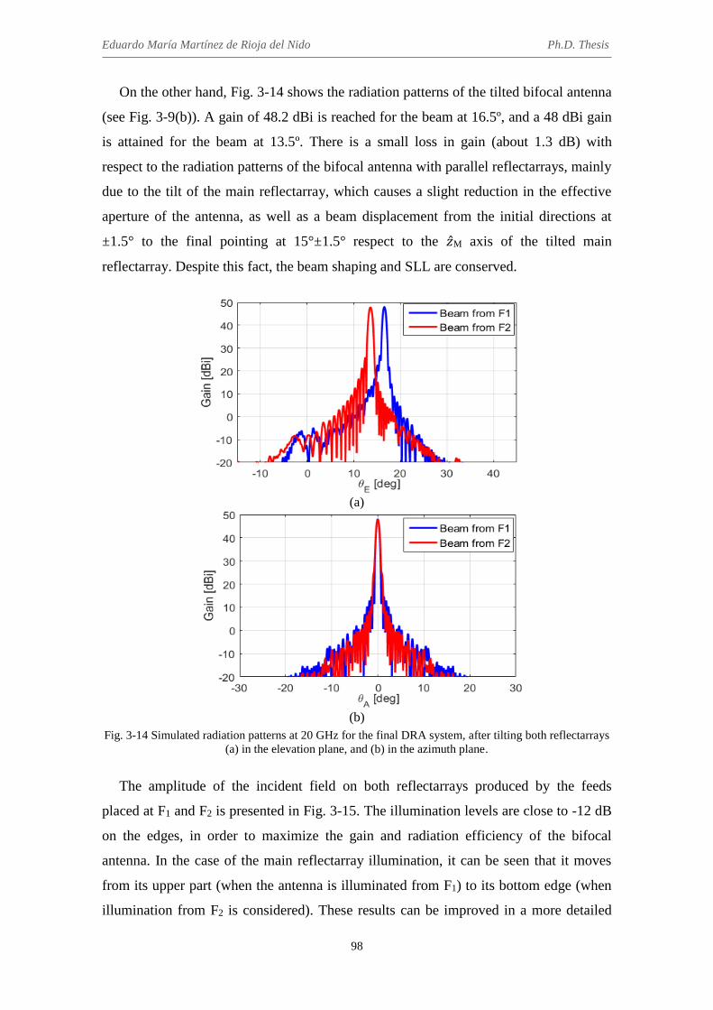
Eduardo María Martínez de Rioja del Nido Ph.D. Thesis
98
On the other hand, Fig. 3-14 shows the radiation patterns of the tilted bifocal antenna
(see Fig. 3-9(b)). A gain of 48.2 dBi is reached for the beam at 16.5º, and a 48 dBi gain
is attained for the beam at 13.5º. There is a small loss in gain (about 1.3 dB) with
respect to the radiation patterns of the bifocal antenna with parallel reflectarrays, mainly
due to the tilt of the main reflectarray, which causes a slight reduction in the effective
aperture of the antenna, as well as a beam displacement from the initial directions at
±1.5° to the final pointing at 15°±1.5° respect to the �̂�M axis of the tilted main
reflectarray. Despite this fact, the beam shaping and SLL are conserved.
(a)
(b)
Fig. 3-14 Simulated radiation patterns at 20 GHz for the final DRA system, after tilting both reflectarrays (a) in the elevation plane, and (b) in the azimuth plane.
The amplitude of the incident field on both reflectarrays produced by the feeds
placed at F1 and F2 is presented in Fig. 3-15. The illumination levels are close to -12 dB
on the edges, in order to maximize the gain and radiation efficiency of the bifocal
antenna. In the case of the main reflectarray illumination, it can be seen that it moves
from its upper part (when the antenna is illuminated from F1) to its bottom edge (when
illumination from F2 is considered). These results can be improved in a more detailed

Chapter 3. Application of the bifocal technique to dual reflectarray configurations
99
design of the antenna by pointing to different zones of the sub-reflectarray with each
feed, so as to obtain a more centered illumination on the main reflectarray. In a
Cassegrain system (like the current one), the lower feed (F1) should point to the lower
part of the sub-reflectarray, while the upper feed (F2) should point to its upper part. An
oversized sub-reflectarray could be used for this purpose, but always keeping in mind
the problem of the blockage caused by the sub-reflector.
(a) (b)
(c) (d)
Fig. 3-15 Amplitude (dB) of the incident field on the sub-reflectarray for (a) F1 and (b) F2, and on the main reflectarray for (c) F1 and (d) F2.
After the calculation of the radiation patterns for the two feeds placed at F1 and F2,
additional feeds are considered in order to evaluate the multi-beam performance of the
antenna. Since the distance between the foci is d = 20 cm and the diameter of the horns
is estimated at 65 mm, only two additional feeds can be placed between those at F1 and
F2, with a separation of 66.7 mm between the phase centers of consecutive horns. Then,
two more feeds have been added in the extremes of the feed array, placed on the xz-
plane, so as to generate a total of six beams. The simulated radiation patterns in the

Eduardo María Martínez de Rioja del Nido Ph.D. Thesis
100
elevation plane for the six beams are shown in Fig. 3-16 (solid lines). As can be seen,
the separation between adjacent beams is around 1º, the gain varies from 47.7 dB to
48.2 dB, and SLL is lower than -21 dB for all the beams. Moreover, the beams
generated by a reference reflectarray antenna in a single reflector configuration,
designed to provide the same gain by using adjacent feeds with 66.7 mm separation,
have been obtained and included in Fig. 3-16 (dashed lines). As can be seen, the
monofocal beams present around 1.5º-1.6º separation, and the main lobe of the extreme
beams is considerably broadened with respect to the main lobe of the bifocal beams. As
can be seen, the proposed bifocal method allows to obtain a similar performance in
terms of gain and SLL for all the beams, and also to generate closer beams with non-
overlapping feeds than in the single-focus design.
Fig. 3-16 Simulated radiation patterns at 20 GHz in the xz-plane for the bifocal dual reflectarray antenna
(solid lines) and the single-focus reference antenna (dashed lines).
The performance of the bifocal antenna has been also evaluated for the beams out of
the plane where the bifocal synthesis was performed (xz-plane). The pattern contours of
38 dBi, 45 dBi (which approximately corresponds to -3 dB with respect to the
maximum gain) and 47.5 dBi are shown in Fig. 3-17 for the beam produced from focus
F1 (θ = 16.5º) and a ring of five adjacent beams with 1º separation with respect to the
central one. Note that the three beams in the plane v = 0 are produced by the horns no.
1, 2 and 3, according to Fig. 3-16. As can be seen, the minimum separation between
adjacent beams that can be achieved in the current design is limited by the diameter of
the feed-horns. To obtain less than 1º separation, the size of the horns must be reduced
(less directive horns), leading to the necessity of oversized reflectors.

Chapter 3. Application of the bifocal technique to dual reflectarray configurations
101
Fig. 3-17 Radiation pattern contours of 38 dBi, 45 dBi and 47.5 dBi for the beams produced from focus
F1 of the bifocal antenna and a ring of five beams.
Although the results in this section are presented only at 20 GHz (Tx frequency from
a satellite in Ka-band), the combination of the proposed bifocal method with the
capabilities of polarization and frequency discrimination of reflectarrays, will allow to
perform independent bifocal synthesis for each frequency (Tx and Rx) and/or
polarization. This will require the use of appropriate reflectarray cells that will provide
independent phase control at different frequencies and/or polarizations.
3.3 Considerations on the design of bifocal dual reflectarray antennas
The initial conditions of the synthesis have an important effect on the performance of
the bifocal algorithm, and particularly, on the results obtained for the phase distributions
and relative dimensions of the two reflectarrays. The setting of very extreme or
improper initial conditions may lead to convergence problems of the algorithm, not
being possible to reach a valid solution for the bifocal design of the antenna with such
characteristics. For this reason, it may be useful to count on a single-focus design
(reference reflector or dual reflectarray antenna) that serves to estimate the main
geometrical parameters of the bifocal antenna, at least as a first approximation. Some
additional aspects to be taken into account concerning the performance of the bifocal
algorithm are set out below.

Eduardo María Martínez de Rioja del Nido Ph.D. Thesis
102
3.3.1 Setting of the beam spacing
The minimum separation that can be achieved between adjacent beams in a SFPB
multi-beam antenna system is limited by the size of the feeds, which is fixed to provide
an optimum illumination according to the F/D ratio of the antenna. To achieve a smaller
beam spacing, there are two possible solutions: to reduce the size of the feeds (less
directive feeds), which forces to increase the antenna size in order to maintain low
spillover, or to keep using the same feeds and increase both the focal distance and the
antenna diameter (thus preserving the F/D ratio of the antenna). Note that both solutions
end up with an oversized antenna, in order to avoid the problem of overlapping feeds.
On the other hand, the bifocal technique allows a certain degree of control over the
separation between adjacent beams for a given feed spacing by properly setting the
initial parameters of the design algorithm. Regarding the performance of the bifocal
antenna, it can be designed to obtain a larger beam spacing, a smaller beam spacing or a
similar beam spacing to the one provided by the equivalent single-focus design. Bifocal
antennas with wider beam spacing are suitable for those applications in which a large
beam scanning angle is required [17]. In the case of this thesis, we are more interested
in the design of bifocal antennas with a reduced separation between adjacent beams,
which can be a potential alternative for current multi-beam satellite antennas in Ka-
band.
To illustrate the performance of the bifocal technique for each of the three possible
design cases, the bifocal algorithm has been executed maintaining some of the initial
parameters of the DRA system designed in the previous sections and changing only the
directions of the beams. The initial parameters of the bifocal synthesis for the three
designs (Design 0, Design 1 and Design 2) are shown in Table 3-1. The samples and the
interpolated curves of the phase derivative on each reflectarray can be seen in Fig. 3-18
for the three design cases, while the resulting bifocal phase functions in the xz-plane are
presented in Fig. 3-19.
As can be inferred from the relation of the phase derivative samples, the design with
the largest beam spacing (Design 1) leads to similar sizes for both reflectarrays, as well
as to the smoothest phase variation on the main reflectarray. The first factor obliges to
design centered or slightly offset geometries, where the antenna will present blockage
from the sub-reflectarray (in [17], this blockage is avoided by a 90º twist of polarization
on the main reflectarray).

Chapter 3. Application of the bifocal technique to dual reflectarray configurations
103
(a)
(b)
Fig. 3-18 Interpolation of the phase derivative samples obtained on the: (a) sub-reflectarray and (b) main reflectarray.
TABLE 3-1
INITIAL PARAMETERS OF THE BIFOCAL SYNTHESIS
Parameter Design 0 Design 1 Design 2
L1 1 m 1 m 1 m L2 1.5 m 1.5 m 1.5 m d 0.2 m 0.2 m 0.2 m
θb1 +1.5º +3º +0.75º θb2 -1.5º -3º -0.75º

Eduardo María Martínez de Rioja del Nido Ph.D. Thesis
104
(a)
(b) Fig. 3-19 Bifocal phase curves obtained after the integration of the interpolated phase derivatives on the:
(a) sub-reflectarray and (b) main reflectarray.
The design with the smallest beam spacing (Design 2) produces the fastest phase
variation on the main reflectarray, and the largest size of the main reflectarray for a
fixed size of the sub-reflectarray. Meanwhile, the original design (Design 0) provides an
intermediate solution for the phase variation on both reflectarrays. Both designs, the one
with θb = ±1.5º and the one with θb = ±0.75º, are suitable for the deployment of dual
offset antenna geometries that will minimize blockage from the sub-reflectarray,
allowing the antenna for operating in dual-polarization. Also, note that the shape of the
bifocal phase curve obtained on the sub-reflectarray changes from a concave response
(Design 1, with θb = ±3º) to a convex one (Design 2, with θb = ±0.75º).

Chapter 3. Application of the bifocal technique to dual reflectarray configurations
105
The previous effects on the phases can be associated to a shifting of the virtual focal
position in the equivalent monofocal system: when the bifocal technique is applied to
increase the beam spacing, the virtual focus moves away from the sub-reflectarray (in
the direction of positive z-axis), which results in similar sizes for both reflectarrays and
a concave phase response on the sub-reflectarray. Conversely, when the bifocal
technique is used to reduce the beam spacing, the virtual focus moves towards the sub-
reflectarray, producing highly offset geometries with a very large main reflectarray and
a convex phase response on the sub-reflectarray.
3.3.2 Design of a Gregorian system
Regarding the bifocal designs that have been performed so far, the beam generated
from F1 has been always considered to radiate at θb1 > 0º (according to the reference
system shown in Fig. 3-1), while the beam produced from F2 presents θb2 < 0º and
fulfills θb2 = -θb1. However, it is also possible to swap the directions of the beams
associated to the foci, so that F1 will generate the beam radiating at θb1 < 0º and F2 will
produce the beam at θb2 > 0º. In that case, the samples obtained on the sub-reflectarray
after applying the bifocal ray-tracing process will grow in the direction of the negative
x-axis, leading to a Gregorian instead of a Cassegrain system (see Fig. 3-20).
Fig. 3-20 Performance of the bifocal ray-tracing in the case of designing for a Gregorian system.

Eduardo María Martínez de Rioja del Nido Ph.D. Thesis
106
As in the case of Cassegrain systems, the bifocal phase curves obtained in the xz-
plane can be rotated around z-axis, and then both reflectarrays can be tilted a certain
angle by applying the previously described phase adjustment routine, in order to achieve
smoother phase distributions. The use of a Gregorian configuration provides similar
results than those obtained with a Cassegrain one, but the latter has been the selected
option for performing the previous designs because it allows a larger equivalent F/D
ratio, resulting in a main reflectarray with a lower number of 360º cycles.
3.3.3 Conclusions on the application of the bifocal method to offset configurations
The bifocal ray-tracing algorithm described in section 3.2.1 can be applied to a DRA
system by considering already tilted reflectarrays in the xz-plane. In this case, the
problem of setting the initial value of the phase derivative at the point S1 on the sub-
reflectarray may not have a unique solution, since the symmetry conditions existing in
the geometry with parallel reflectarrays may not be applicable here. Several options are
then possible for Φ’x(S1), provided that they fulfill the conditions given in eq. (3-2).
Moreover, the extension of the 2D design performed in the xz-plane to a 3D solution is
not trivial (this aspect will be addressed in Chapter 5). This is the main reason for
starting from an axially-symmetrical geometry with parallel reflectarrays, in which the
phases obtained in the xz-plane can be rotated around z-axis. However, the proposed
bifocal method presents some geometrical constraints that limit its use for the design of
any bifocal DRA configurations.
First, the initial positions of the foci must be symmetrical with respect to z-axis, in
order to provide a focal ring after the rotation of the bifocal phase curves. Note that the
relative positions of the foci with respect to the sub-reflectarray are conserved in the
subsequent process of tilting the reflectarrays. Furthermore, if the reflectarrays are tilted
a large angle with respect to their initial positions in parallel planes, or if the tilting
angle of one reflectarray is much greater than that of the other, the resulting bifocal
antenna presents an important degradation of its radiation patterns with respect to those
obtained with the reflectarrays in parallel planes.
Consequently, the proposed bifocal method can be suitable for the design of both
centered and offset DRA configurations with parallel reflectarrays, and also Cassegrain
configurations which require a small adjustment in the tilting of both reflectarrays, as in

Chapter 3. Application of the bifocal technique to dual reflectarray configurations
107
the case shown in Fig. 3-9. On the other hand, this method is not recommended for
highly offset geometries, such as the compact-range DRA configuration in [71], which
demand the implementation of a more general bifocal algorithm (as will be shown in
Chapter 5).
3.4 Preliminary design of bifocal dual reflectarray configurations for
multi-beam satellite antennas in Ka-band
The separation between adjacent beams required for the current multi-spot satellite
applications in Ka-band is so small (typically 0.56º) that it would not be possible to
produce all the beams with a single reflector antenna, as it would require overlapping
feeds (unless using a highly-oversized shaped reflector, as in [90]). Therefore, four
reflector antennas are commonly used to generate all the beams of the four colour
coverage scenario (one reflector per colour), both in transmission (Tx) and reception
(Rx), using a SFPB architecture [82].
Reflectarray antennas are a potential alternative for this kind of multi-spot
applications with frequency and polarization reuse, but firstly it is necessary to evaluate
their performance for the generation of multiple beams and their capability to provide
closely-spaced beams. For this purpose, the bifocal technique has been applied to the
design of multi-beam dual reflectarray antennas in Ka-band, considering two different
approaches: generation of adjacent beams with a smaller separation than in a single-
focus antenna, and improvement of the antenna performance for the edge beams.
Although the results presented in this section are only preliminary, they are useful to get
an idea about the performance of the bifocal technique in each of these two cases.
3.4.1 Generation of adjacent beams
The bifocal technique has been applied to a Cassegrain dual reflectarray
configuration in order to obtain beam spacing compression, meaning that the separation
between beams generated with adjacent feeds is so small that it could not be achieved
with a single-focus antenna, as it would require overlapping feeds. The beam
compression ratio (BCR) can be defined as the beam spacing achieved applying the
bifocal technique divided by the beam spacing achieved without the bifocal technique,
considering the same feed spacing. In this case, the bifocal antenna will provide 0.56º of

Eduardo María Martínez de Rioja del Nido Ph.D. Thesis
108
beam spacing, which is the required value for current multi-beam applications in Ka-
band. This separation would traditionally require 50% feed overlap in a single-focus
antenna, so the BCR is close to 2.
The geometry of the designed Cassegrain dual reflectarray antenna is shown in Fig.
3-21. The diameters of the sub- and main reflectarrays are DS = 80 cm and DM = 1.9 m,
respectively, in order to provide around 50 dBi of gain at 20 GHz. A linear array of
seven non-overlapping 54 mm feeds has been considered, where the phase centers of the
second and the sixth feeds are placed at F1 and F2 (the foci of the bifocal antenna),
respectively. Therefore, the distance between foci is d = 21.6 cm. The beam directions
associated to the foci are θb1 = 1.12º and θb2 = -1.12º, in order to obtain 0.56º of final
separation between the beams generated by adjacent feeds. The other parameters of the
bifocal synthesis are: L1 = 0.9 m and L2 = 2.4 m.
Fig. 3-21 Geometry of the bifocal dual reflectarray antenna to provide 0.56º of beam spacing.
A realistic model of a Ka-band feed-horn that has been characterized by Astrium
[82] is considered for this study (see Fig. 3-22). The feed-horn presents a diameter of 54
mm and produces a taper level of -12 dB at 20 GHz on the sub-reflectarray edges when
illuminating with 36º subtended angle. For simulation purposes, the electromagnetic
field radiated by the feed-horn at 20 GHz has been modeled by a cosq(θ) function with a
q-factor equal to 28.

Chapter 3. Application of the bifocal technique to dual reflectarray configurations
109
Fig. 3-22 Engineering model of a user/gateway feed chain [82].
The high value of the BCR (≈ 2) affects significantly the performance of the bifocal
algorithm. First, a lower number of points is obtained in the xz-plane after executing the
bifocal ray-tracing routine, which difficulties the subsequent interpolation of the phase
derivative samples. Second, the bifocal phase curves of both reflectarrays present a
steeper slope (although it has not been applied to the current design, both reflectarrays
can be tilted to reduce the number of 360º cycles in their phase distributions, as
explained in section 3.2.4). Finally, there is a different spatial relationship between the
points obtained on both reflectarrays in the same iteration of the algorithm.
The simulated radiation patterns at 20 GHz in the principal planes for the two beams
generated by the foci of the bifocal antenna have been computed assuming ideal
reflectarray elements and are shown in Fig. 3-23. A gain close to 46.2 dBi is achieved
for both beams, while SLL is around -16 dB with respect to the maximum. The two
beams point in the specified directions (±1.12º), so a final separation of 0.56º is
obtained between the beams generated by contiguous feeds placed in the xz-plane, as
can be seen in Fig. 3-24.
The main characteristics of the beams (gain, SLL and beamwidth) produced by the
bifocal DRA system are presented in Table 3-2. Despite achieving the required degree
of beam spacing compression, the bifocal antenna presents a serious efficiency problem
that can be noticed in the reduced gain of the beams (between 45.5 and 46.8 dBi), which
is lower than the gain expected for a 1.9 m main aperture (it should be between 50 and
51 dBi).

Eduardo María Martínez de Rioja del Nido Ph.D. Thesis
110
(a)
(b)
Fig. 3-23 Simulated radiation patterns at 20 GHz for the two beams generated by the foci of the bifocal antenna: (a) in the xz-plane (elevation), (b) in the orthogonal plane in the direction of the beam (azimuth).
Fig. 3-24 Simulated radiation patterns at 20 GHz in the xz-plane for the bifocal antenna to provide 0.56º
of beam spacing.

Chapter 3. Application of the bifocal technique to dual reflectarray configurations
111
To better understand the cause of the efficiency problem, the amplitude distributions
of the incident field over the symmetry axis of both reflectarrays produced by the feeds
placed at the foci of the bifocal antenna, are shown in Fig. 3-25. The illumination levels
on the edges of the sub-reflectarray are equal or lower than -12 dB, since a proper
illumination has been ensured by using the 54-mm feeds. However, the illumination on
the edges of the main reflectarray is very high, thus leading to higher spillover and
lower radiation efficiency for the bifocal antenna.
Fig. 3-25 Amplitude (dB) of the incident field on the two reflectarrays produced by F1 and F2.
Introducing some modifications in the initial conditions of the bifocal synthesis or
changing the antenna configuration (for example, using a Gregorian system) does not
mitigate this problem, which is caused by the high degree of beam spacing compression
(BCR = 2) imposed in the design of the bifocal antenna. The only possible solution to
reduce spillover and reach around 50 dBi gain would be to increase the size of the main
TABLE 3-2 MAIN CHARACTERISTICS OF THE BEAMS (BCR = 2)
No. beam Beam
direction (º) Gain (dBi)
Beamwidth at 43 dBi (º)
SLL
1 -1.68 45.63 0.613 17.19 2 -1.12 46.12 0.612 17.39 3 -0.56 46.65 0.609 17.94 4 0 46.78 0.606 18.15 5 0.56 46.62 0.594 17.07 6 1.12 46.14 0.565 15.79 7 1.68 45.51 0.537 14.88

Eduardo María Martínez de Rioja del Nido Ph.D. Thesis
112
reflectarray, but this implies using a very large reflectarray, around 3.8 m in diameter
(which is twice the size that was initially considered).
3.4.2 Improvement of the extreme beams
The bifocal technique has been used to correct beam aberration and improve the
multi-beam performance of the dual reflectarray antenna, without reducing the beam
spacing. In this case, the bifocal antenna will provide a separation of 1.12º between
adjacent beams, which is twice the separation provided in the previous section. This
separation can be also achieved with a single-focus antenna without using overlapping
feeds, so the BCR value is equal to 1.
The bifocal algorithm has been applied to the compact-range DRA geometry shown
in Fig. 3-26. The diameters of the two reflectarrays are DM = 1.9 m and DS = 1.4 m. An
array of eleven non-overlapping feeds has been used to illuminate the antenna, so that
the phase centers of the fourth and the eighth feeds are placed at F1 and F2, respectively.
The feed-horns present the same characteristics that those used in the previous section
(54 mm in diameter and simulated with q = 28), so distance between foci is d = 21.6 cm.
The beam directions associated to the foci, θb1 = 28.24º and θb2 = 23.76º, have been
selected to avoid blockage from the sub-reflectarray and provide 1.12º of spacing
between beams generated by adjacent feeds. Due to the large offset of the antenna
configuration, the design has been performed only in the xz-plane, according to what
was exposed in section 3.3.3.
Fig. 3-26 Geometry of the bifocal dual reflectarray antenna to provide 1.12º of beam spacing.

Chapter 3. Application of the bifocal technique to dual reflectarray configurations
113
The simulated radiation patters at 20 GHz in the xz-plane for the two beams
produced by the foci of the bifocal antenna are shown in Fig. 3-27. The gain of the
beams has been estimated based on the beamwidth obtained at -3 dB in the xz-plane,
and assuming that the design of the bifocal antenna can be extended from 2D to 3D in
order to achieve the same beamwidth in the two orthogonal planes. Under these
conditions, a gain close to 51 dBi is obtained for both beams. Moreover, SLL is around
-22 dB with respect to the maximum gain and the 3-dB beamwidth is 0.58º. The new
requirement of beam spacing (associated to BCR = 1) produces reasonable illumination
tapers on both reflectarrays, as can be seen in Fig. 3-28, and the radiation efficiency is
increased with respect to the case with BCR = 2. The compact range geometry forces to
use a larger sub-reflectarray, although proper illumination is obtained for all the feeds.
Fig. 3-27 Simulated radiation patterns at 20 GHz in the xz-plane for the two beams generated by the foci
of the bifocal antenna.
Fig. 3-28 Amplitude (dB) of the incident field on the two reflectarrays produced by F1 and F2.
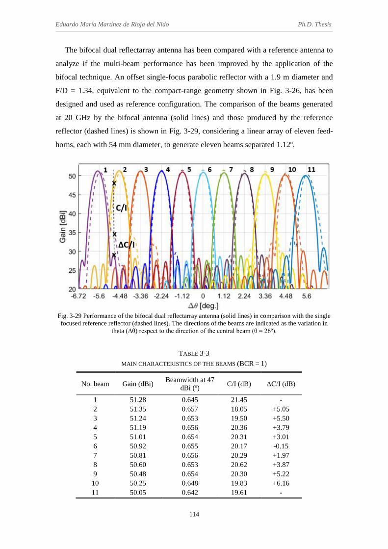
Eduardo María Martínez de Rioja del Nido Ph.D. Thesis
114
The bifocal dual reflectarray antenna has been compared with a reference antenna to
analyze if the multi-beam performance has been improved by the application of the
bifocal technique. An offset single-focus parabolic reflector with a 1.9 m diameter and
F/D = 1.34, equivalent to the compact-range geometry shown in Fig. 3-26, has been
designed and used as reference configuration. The comparison of the beams generated
at 20 GHz by the bifocal antenna (solid lines) and those produced by the reference
reflector (dashed lines) is shown in Fig. 3-29, considering a linear array of eleven feed-
horns, each with 54 mm diameter, to generate eleven beams separated 1.12º.
Fig. 3-29 Performance of the bifocal dual reflectarray antenna (solid lines) in comparison with the single focused reference reflector (dashed lines). The directions of the beams are indicated as the variation in
theta (Δθ) respect to the direction of the central beam (θ = 26º).
TABLE 3-3
MAIN CHARACTERISTICS OF THE BEAMS (BCR = 1)
No. beam Gain (dBi) Beamwidth at 47
dBi (º) C/I (dB) ΔC/I (dB)
1 51.28 0.645 21.45 - 2 51.35 0.657 18.05 +5.05 3 51.24 0.653 19.50 +5.50 4 51.19 0.656 20.36 +3.79 5 51.01 0.654 20.31 +3.01 6 50.92 0.655 20.17 -0.15 7 50.81 0.656 20.29 +1.97 8 50.60 0.653 20.62 +3.87 9 50.48 0.654 20.30 +5.22 10 50.25 0.648 19.83 +6.16 11 50.05 0.642 19.61 -

Chapter 3. Application of the bifocal technique to dual reflectarray configurations
115
The main characteristics of the beams (gain, beamwidth, single-entry C/I and
improvement in the single-entry C/I) produced by the bifocal antenna are summarized in
Table 3-3. The single-entry C/I (where the interference is produced by the radiation of
the adjacent beams) has been calculated within a 0.65º beamwidth, which
approximately corresponds to a 47 dBi gain, and varies between 18.05 dB and 20.62 dB
for the eleven beams. The lowest C/I values are associated to the interferences produced
by the extreme beams, which are the most broadened beams. As can be seen in Fig.
3-29, the bifocal technique provides a better shaping of the main lobe and lower SLL
for the extreme beams, which allows for a significant improvement in C/I with respect
to the reference single-focused antenna (more than 5 dB). For the rest of the beams, the
bifocal antenna presents around 2-3 dB of improvement in C/I, except for the central
beam, which presents a slightly worse performance than in the single-focus case. Note
that the improvement in C/I for the beams no. 1 and no. 11 cannot be calculated in a
precise way, since the higher interference would be produced by the adjacent beams
radiating at -6.72º and 6.72º, which have not being considered in the simulations.
3.4.3 Conclusions
The bifocal technique has been applied to different dual reflectarray configurations
for the design of multi-beam satellite antennas in Ka-band, in order to evaluate its
performance for the generation of adjacent beams with 0.56º of spacing and improving
the results obtained for the extreme beams. With respect to the first objective, the
bifocal antenna is able to provide a high degree of beam spacing compression (by a
factor of 2) with respect to conventional single-focus antennas, so as to generate
adjacent beams with 0.56º separation by using contiguous and non-overlapping feeds.
However, the radiation efficiency of the bifocal antenna is not as high as it should be,
due to the high spillover on the main reflectarray (which should be significantly
oversized to overcome this problem). On the other hand, when the bifocal technique is
applied to obtain the same beam spacing than in the equivalent single-focus design, the
bifocal antenna provides better results for the extreme beams (in terms of SLL, C/I and
beam shaping) than those of the monofocal case, while presenting similar values of gain
and radiation efficiency.
After checking the results shown in the previous sections, it can be concluded that
the most interesting option for the design of a multi-beam bifocal DRA would be

Eduardo María Martínez de Rioja del Nido Ph.D. Thesis
116
probably a combination of the two approaches. The bifocal technique can be applied to
provide a reduced beam spacing (a high degree of beam spacing compression is not
suitable, in order to maintain good radiation efficiency for the bifocal antenna), at the
same time as correcting beam aberration and improving the performance of the extreme
beams with respect to the equivalent single-focus antenna. Examples of this way of
proceeding will be shown in Chapters 5 and 6.
3.5 Conclusions
A bifocal technique has been proposed for dual reflectarrays antennas. The problem
of the 3D design is solved by starting from an axially-symmetrical geometry with
parallel reflectarrays, in which a 2D GO algorithm is applied. The bifocal phase curves
obtained in the offset plane can be rotated around the symmetry axis, and then, both
centered and offset configurations are possible by selecting specific parts of these
revolution surfaces. Offset configurations are preferable, as they allow to reduce
blockage from the feeds and the sub-reflectarray, but the phase distributions present a
high number of 360º cycles in this case, as a consequence of the large size of both
reflectarrays and the initial conditions of the synthesis. For this reason, both
reflectarrays can be tilted a certain angle, at the same time as their phases are adjusted to
compensate the tilting and maintain the bifocal characteristic of the original design (the
phase adjustment will provide smoother phase distributions on both reflectarrays).
A preliminary study on the capabilities of the bifocal technique to reduce beam
spacing and improve the performance of the edge beams for multi-beam satellite
antennas in Ka-band has been carried out. The results show that the bifocal technique
allows to reduce beam spacing by a factor of 2 with respect to the equivalent single-
focus antenna (and without using overlapping feeds), but at the cost of a lower radiation
efficiency. The main reflectarray has to be significantly oversized (up to 4 m in
diameter) to overcome this problem. On the other hand, the bifocal technique can be
applied to correct beam aberration, providing the same beam spacing than in the single-
focus case. As a result, a better performance is obtained for the extreme beams, with
satisfactory results for the gain and radiation efficiency of the antenna.
Finally, note that the bifocal antennas have been designed to operate at 20 GHz (Tx
frequency from a satellite in Ka-band), but a similar bifocal process can be carried out

Chapter 3. Application of the bifocal technique to dual reflectarray configurations
117
to obtain the required phases on both reflectarrays at 30 GHz (Rx frequency in Ka-
band), in order to generate the beams in reception. Then, appropriate reflectarray cells
that will provide independent phase control at Tx and Rx frequencies can be used to
implement the phase distributions on both reflectarrays, allowing for the design of
transmit and receive multi-beam satellite antennas in Ka-band.

118

119
Chapter 4
Bifocal technique applied to dual transmitarray antennas
4.1 Introduction
The bifocal technique described in Chapter 3 can be applied to the design of dual
transmitarray antennas (DTA), in a similar way to the case of dual reflectarrays. The use
of transmitarrays provides some interesting advantages, as it eliminates blockage from
the feeds and allows for the use of centered and rotationally-symmetrical geometries,
thus simplifying the design process of the bifocal antenna. Besides these similarities
with dielectric lenses, transmitarrays offer the same flexibility as reflectarrays when
implementing the capabilities of the unit cells (flat panels, manufactured technology of
printed circuits, dual polarization [45], [117], possibility of reconfiguration of the beam
by adding controllable phase shifters in the transmitarray cells [47], [118], [119], etc.).
The design of transmitarray cells requires finding a cell topology that provides at least
360º of phase range in a required bandwidth, at the same time as presenting full
transmission and zero reflection within the operating band. In the literature, two main
approaches have been reported to design transmitarray antennas (see Fig. 4-1): multiple
stacked frequency selective surfaces (FSS) [43]-[45], [120]-[124] and transmitter-
receiver antenna [42], [47], [125], [126].
The design process of a passive transmitarray based on stacked FSSs focuses on the
synthesis and subsequent design of one filter for each phase state, assuming that the
phase of the transmitted wave is discretized in a fix number of states, for example 8
states for 3-bit quantization, as in references [43], [44]. There are two main strategies to
achieve the phase-shift. The first one consist on making that each filter provides the

Eduardo María Martínez de Rioja del Nido Ph.D. Thesis
120
same electrical performance, but centered at a different frequency, thus producing the
required phase shift [120]-[122]. The other strategy consists on obtaining different
slopes of the amplitude curves and bandwidths for each phase state, where all the states
are centered at the same frequency [43]. The latter strategy usually requires larger
ranges of variation of the equivalent capacities and inductances than the other one, so
that it usually requires different types of metallizations to cover the entire range of 360º
[43]. For both strategies, the approach based on filter theory exhibits electrical
limitations, since it involves the use of canonical structures (Chebyshev, Elliptical, etc.).
(a) (b)
Fig. 4-1 Example of the two approaches commonly used to design a transmitarray cell: (a) multiple stacked FSSs [121] and (b) transmitter-receiver antenna [40].
The theoretical limitations of canonical structures imply high order filters to achieve
a phase-range of at least 360º. In [120], it was demonstrated that 4 or more layers are
necessary to reach a phase range of 360º assuming an admissible level of losses of 1 dB
(antenna efficiency of 56 %), whereas that the number of layers gets down to 3 if the
admissible losses increases up to 3 dB (antenna efficiency of 35 %). These theoretical
limitations are coupled with other physical limitations. By one hand, the values of the
capacitances, inductances and topology, which result from the canonical synthesis of the
filter, must be physically provided by the cell. Otherwise, the performance of the filter
in terms of bandwidth and matching worsens, resulting in reduction of bandwidth and
efficiency at antenna level. On the other hand, the synthesis of two canonical filters that
exhibit similar bandwidth and ripple, but each one centred at a different frequency,
implies different line lengths for each filter, so that each phase state of the transmitarray
must have an appropriate thickness. However, the cells that compose the transmitarray
antenna must present the same thickness, so a variable ripple of the bandpass must be
assumed, resulting in a deterioration of the filtering structure and antenna performance.

Chapter 4. Bifocal technique applied to dual transmitarray antennas
121
Several works have been reported on increasing the performance of transmitarrays
using the approach based on FSSs. Most of them are focused on improving both the
bandwidth and the phase range using a relatively short number of layers, so that the
efficiencies are relatively far of those required in space applications. In [121], a
transmitarray antenna composed by four layers based on dual-resonant double square-
rings elements is shown, which exhibits 1-dB gain bandwidth of 7.5% and antenna
efficiency of 47% at 30 GHz. In [122], the use of polarization insensitive filters using
thin thicknesses (<0.6·λ) provides a 1-dB gain bandwidth of 10.2%, although at the
expense of a reduced efficiency (34%) and the use of an additional layer (5 layers). The
strategy of considering several cell topologies in the same array was proposed in [43] to
improve the bandwidth, each of which designed to cover a certain phase interval of the
complete 360º; in this case, these topologies allow finding a large range of the required
circuital variables after the synthesis, thus achieving 12.5% bandwidth of (-1 dB
criteria) and 45% efficiency at 20 GHz using four layers.
Concerning the antenna efficiency, in [123] the efforts were made on reducing the
losses of the cells (thus increasing the efficiency up to reach 55%), although at expense
of assuming a small bandwidth (7.4%, -1 dB criterion). A trade-off between efficiency
and bandwidth was also presented in [124], where both features are improved by using
four layers and double square loop elements on dielectric materials, which exhibits 1-dB
gain bandwidth of 11.7% and efficiency of around 48%. In this case, the improvement
and the trade-off that includes the efficiency are achieved by optimizing the phase
distribution on the aperture.
Other important objective for the developing of transmitarray antennas for space
communications has been recently addressed in [45], where a transmitarray antenna
exhibiting two independent beams for each linear polarization has been demonstrated.
The transmitarray is composed by 3 stacked FSSs in X-band (see Fig. 4-2(a)), assuming
canonical rectangular shapes for the patches, which is essential to ensure independence
of the polarisations and low cross polar levels. However, stacked patches are able to
provide only limited values of the circuital equivalent parameters, which implies
limitations in terms of phase-range (210º, 1 dB of tolerable ripple), bandwidth (7%, -1
dB criterion), efficiency (which is especially small due to the phase quantization) or
SLL. The difficulty of achieving independent dual linear polarization using FSSs is due
to the fact that canonical shapes must be used, which is contrary to what is usually

Eduardo María Martínez de Rioja del Nido Ph.D. Thesis
122
needed to increase the phase-range or the bandwidth. In [43], the physical complexity of
the elements used to improve the electrical performance of transmitarrays does not
allow to obtain independent phase-shifting for each polarization.
The second approach to design transmitarray antennas consists on interconnecting
the receiver and transmitter patches using slots on a common ground plane or delay
lines. In [42], it was shown that the use of slots implies phase-ranges limited to 180º and
a narrow bandwidth, being necessary the use of delay lines to overcome these
limitations. Some references have also been focused on improving the electrical
performance of transmitarrays using the antenna approach [117], [125]-[126], which are
able to reach similar specifications than those obtained using FSSs with some additional
advantages. These structures provide more flexibility to control the amplitude of the
transmitted field or to include devices to electronically control the phase [125]. This
flexibility allows for obtaining electrical features such as circular polarization [126],
dual polarization (see Fig. 4-2(b)) [117] or dual band behaviour [46] more easily from
the point of view of the design. However, the resulting antennas are usually more
voluminous and heavier than the transmitarrays based on FSS, imply a more complex
fabrication and can exhibit worse efficiencies due to the losses of the lines and the
internal microwave circuitry.
(a) (b)
Fig. 4-2 Two different transmitarray cells to achieve operation in dual polarization: (a) based on multiple stacked FSSs [45] and (b) based on transmitter-receiver concept and the use of PIN diodes [117].
In this chapter, ideal transmitarray elements will be considered, which present 360º
of phase range to provide the required phase-shift, while presenting at the same time
zero reflection and insertion losses within the operating band.

Chapter 4. Bifocal technique applied to dual transmitarray antennas
123
4.2 Bifocal design procedure for dual transmitarray antennas
Figure 4-3 shows the geometry of the dual transmitarray antenna and its main
parameters, which must be fixed before starting the bifocal design procedure: directions
of the radiated beams (θb1 and θb2), distance between foci (d), distance between the foci
and the first transmitarray (SA) and distance between the two transmitarrays (SB). As in
the bifocal design of dual reflectarrays, a symmetrical arrangement of the foci along the
x-axis is considered: the coordinates of the focal points are (xF1, yF1, zF1) = (-d/2, 0, 0)
and (xF2, yF2, zF2) = (d/2, 0, 0). The beam directions are also symmetric with respect to
the horizontal axis: θb1 = -θb2.
Fig. 4-3 Geometry of the dual transmitarray antenna and example of performance of the bifocal ray
tracing routine in the xz-plane.
Each transmitarray cell will introduce a certain phase shift between elements such
that the incident wave coming from the feed with an angle θi will produce a transmitted
wave with an output angle θo. As in the case of reflectarrays, it can be shown that the
incidence and output angles will fulfill the following relation with the phase derivative
along the transmitarray profile (∂Φ/∂x):
Φ′𝑥 =𝜕Φ
𝜕𝑥 =
2𝜋
𝜆· (sin 𝜃𝑖 − sin 𝜃𝑜) (4-1)
An iterative ray-tracing algorithm that applies eq. (4-1) for both transmitarrays and
alternates transmitted and received rays in the same way that is described in section

Eduardo María Martínez de Rioja del Nido Ph.D. Thesis
124
3.2.1 will provide a set of points (Pi and Qi) that characterize each transmitarray, with
the associated values of the phase derivative at those points. Due to the symmetry of the
antenna configuration, the required phases on both transmitarrays will be even functions
with respect to x, so their phase derivative will be zero at x = 0. Therefore, the first
iteration of the bifocal algorithm will start with a transmitted ray from F1 that impinges
on the first transmitarray at P1 = (0, 0, SA), with Φ’x(P1) = 0, as shown in Fig. 4-3. Like
in the design of dual reflectarray configurations, a second execution of the ray-tracing
routine can be performed in order to double the number of points and improve the
accuracy of the interpolation, starting with a received ray in the direction θb2 that
impinges on the second transmitarray at Q1’ = (0, 0, SA + SB), also with Φ’x(Q1’) = 0.
The phase derivative samples obtained on both transmitarrays will be interpolated by
polynomials, and then integrated to obtain the bifocal phase functions in the xz-plane.
These phases will be rotated around z-axis to obtain a complete solution for the phase
distributions on both transmitarrays. Note that the size of the first transmitarray for a
proper illumination on the second transmitarray (or main transmitarray) can be
estimated based on the relationship between the points obtained in the xz-plane for both
transmitarrays, after applying the ray-tracing algorithm.
A bifocal dual transmitarray antenna, equivalent to the DRA system shown in section
3.2, has been designed at 20 GHz (transmission frequency in Ka-band) with the
following parameters: d = 20 cm, SA = 1 m, SB = 1.5 m, θb1 = 1.5º, and θb2 = -1.5º. The
geometry of the dual transmitarray configuration can be seen in Fig. 4-4, where the
diameters of the transmitarrays are D1 = 0.55 m (for the first transmitarray) and D2 = 1.8
m (for the second transmitarray).
The bifocal phase curves obtained in the xz-plane for each transmitarray can be seen
in Fig. 4-5. The behavior of the phases is very similar to the case of the dual reflectarray
antenna shown in section 3.2: a convex response on the sub-transmitarray and a concave
one on the main transmitarray. The points from x = 0 m to x = 0.275 m have been
chosen for constituting the first reflectarray (0.55 m in diameter), and the associated
points from x = 0 m to x = 0.9 m, for the main reflectarray (1.8 m in diameter). The
bifocal phase distributions (in degrees) that must be implemented on each transmitarray
are shown in Fig. 4-6. These distributions present a lower number of 360º cycles than in
the equivalent dual reflectarray antenna with parallel reflectarrays.

Chapter 4. Bifocal technique applied to dual transmitarray antennas
125
Fig. 4-4 Geometry of the bifocal dual transmitarray antenna.
(a) (b)
Fig. 4-5 Phases curves obtained with the bifocal technique in the xz-plane: (a) for the first transmitarray and (b) for the second transmitarray.
(a) (b)
Fig. 4-6 Bifocal phase-shift distributions (in degrees) obtained for: (a) the first transmitarray and (b) the second transmitarray.
The simulated radiations patterns of the bifocal dual transmitarray antenna at 20 GHz
in the elevation and azimuth orthogonal planes are shown in Fig. 4-7. As can be seen, a
gain close to 50 dBi is reached for both beams, which present a 3-dB beamwidth of
0.57º and SLL lower than -25 dB respect to the maximum gain. The simulations have

Eduardo María Martínez de Rioja del Nido Ph.D. Thesis
126
been performed considering ideal transmitarray elements and a cosq(θ) function with q =
50 to model the electromagnetic field radiated by the feed-horns, which provides around
-12 dB illumination on the edges of the first transmitarray (according to this
illumination, the diameter of the horns is estimated at around 65 mm). Since the design
has been performed considering ideal phases, there are no cross-polar components of
the radiated field.
(a)
(b)
Fig. 4-7 Simulated radiation patterns for the dual transmitarray antenna: (a) in the elevation plane, (b) in the azimuth plane
The amplitude distributions of the incident field on both transmitarrays produced by
the feeds placed at F1 and F2 is presented in Fig. 4-8. The illumination levels are close to
-12 dB on the edges, thus maximizing the antenna gain and radiation efficiency. Finally,
the simulated radiation patterns of the bifocal antenna at 20 GHz have been calculated
for a linear array of six horns with 66.7 mm distance between their phase centers (where
the second and the fifth horns are placed at F1 and F2, respectively) and are shown in
Fig. 4-9. As can be seen, the maximum gain is close to 50 dBi, and SLL is around -25

Chapter 4. Bifocal technique applied to dual transmitarray antennas
127
dB for all the beams. A separation of 1º is obtained between adjacent beams generated
by contiguous feeds.
(a) (b)
(c) (d)
Fig. 4-8 Amplitude (dB) of the incident field on the first transmitarray produced by (a) F1 and (b) F2, and on the main transmitarray produced by (c) F1 and (d) F2.
Fig. 4-9 Simulated radiation patterns at 20 GHz in the XZ-plane for the bifocal antenna that provides 1º
separation between adjacent beams.

Eduardo María Martínez de Rioja del Nido Ph.D. Thesis
128
4.3 Considerations on the design of bifocal dual transmitarray
antennas
The bifocal dual transmitarray antenna presents some advantages with respect to the
equivalent dual reflectarray. First, it avoids blockage from the feeds or the first
transmitting structure. This makes it possible the design of centered and rotationally
symmetrical configurations, where the required bifocal phase distributions present a
lower number of 360º cycles. In the design with parallel reflectarrays, the choice of an
offset configuration that minimizes blockage ends up with a very large number of 360º
cycles in the phases, since the slope of the phase curves in the xz-plane becomes greater
as they move away from x = 0. This reduces the potential bandwidth of the reflectarray
and forces a modification of the antenna geometry by tilting both reflectarrays and
correcting their phase distributions, which degrades the performance of the focal ring
obtained after rotating the phases around z-axis (see section 3.2.3). On the other hand,
the dual transmitarray antenna does not require any further adjustment on the bifocal
phases obtained by rotation, allowing to work with a focal ring that contains F1 and F2.
This fact improves the antenna performance for the generation of multiple beams using
a cluster of feeds, as it extends the focal region out of the xz-plane. Finally, the radiation
patterns are less sensitive to surface deformations in the transmitarray than in the
corresponding reflectarray configuration.
One of the problems of the dual transmitarray design consists on the large spacing of
the resulting surfaces along the horizontal axis, as can be seen in Fig. 4-4. The use of
reflectarrays allows for a more compact configuration, such as a Cassegrain or
Gregorian reflector system, while the dual transmitarray requires more space to place
the cluster of feeds and the two transmitarrays. Regarding the latter, there are two
design alternatives that may be interesting to study: reducing the value of SA distance,
so as to integrate the feeds and the first transmitarray into the same sub-system; and
using a small value of SB distance, so that both transmitarrays can be held by the same
supporting structure (this option resembles a dielectric lens). Two bifocal designs
equivalent to the one previously shown in the previous section (Design 0) have been
carried out at 20 GHz, preserving the F/D ratio of the antenna configuration: one with a
small value of SA (Design 1, see Fig. 4-10(a)) and the other with a short SB distance
(Design 2, see Fig. 4-10(b)). The initial parameters of the bifocal synthesis for the three
designs are shown in Table 4-1. Note that the size of the first transmitarray increases as

Chapter 4. Bifocal technique applied to dual transmitarray antennas
129
it is placed closer to the second transmitarray: in Design 1, it is only 26 cm in diameter,
while in Design 2 its diameter is 1.1 m. The comparison of the bifocal phase curves in
the xz-plane obtained for each transmitarray in the three designs is shown in Fig. 4-11.
As can be seen, the phase exhibits a concave response on the first transmitarray and a
convex one on the main transmitarray.
(a)
(b)
Fig. 4-10 Different design options for the bifocal dual transmitarray: (a) with a short SA distance and (b) with a short SB distance.
TABLE 4-1
INITIAL PARAMETERS OF THE BIFOCAL SYNTHESIS
Parameter Design 0 Design 1 Design 2
SA 1 m 0.3 m 2.3 m SB 1.5 m 2.2 m 0.2 m d 0.2 m 0.2 m 0.2 m
θb1 +1.5º +1.5º +1.5º θb2 -1.5º -1.5º -1.5º

Eduardo María Martínez de Rioja del Nido Ph.D. Thesis
130
(a)
(b)
Fig. 4-11 Bifocal phase curves required for the three design configurations: (a) on the first transmitarray and (b) on the second transmitarray.
Regarding the performance of the ray-tracing algorithm, Design 2 provides the
largest number of points to characterize each transmitarray, which facilitates an accurate
interpolation of the phase derivative samples. However, it implies the use of a larger
first transmitarray, and the bifocal phase curves present a steeper slope than in the other
cases, which means more 360º cycles in the phase distributions. To obtain a smoother
phase variation, a possible solution would be to increase the value of SA for the same
beam directions (larger F/D ratio).
On the other hand, Design 1 requires a smaller first transmitarray, which means less
weight and lower fabrication costs. It presents a reasonable number of 360º cycles in the
phases, but at the expense of obtaining a lower number of points in the bifocal

Chapter 4. Bifocal technique applied to dual transmitarray antennas
131
synthesis. This may lead to convergence problems if the initial parameters of the bifocal
algorithm are modified when seeking different configurations to satisfy geometrical
constraints or stringent antenna specifications, as will be shown in the next section.
4.4 Bifocal dual transmitarray antenna to reduce beam spacing
The previous results show the advantages of the proposed bifocal method for the
design of multi-beam dual transmitarray antennas, but a smaller separation between
adjacent beams (around 0.56º) is required in order to fulfill the stringent requirements of
current multi-spot satellite antennas in Ka-band. The bifocal technique can be applied to
reduce the spacing between beams generated with adjacent feeds in a way that would
not be possible in a single-focus antenna, as the corresponding beam spacing would
require overlapping feeds in that case.
The two design alternatives described in section 4.3 have been considered for the
design of such an antenna. The first option (small SA) was discarded after doing several
tests with the bifocal algorithm, as it led to convergence problems with only a few
points corresponding to a very small first transmitarray and a very large second
transmitarray. Conversely, the second design alternative (small SB) seems to be more
feasible, so it has been the option chosen to start this study.
The bifocal technique has been applied to a dual transmitarray configuration in order
to obtain 0.56º of separation between adjacent beams, considering a linear array of six
horns of 54 mm diameter and the same characteristics than those used in section 3.4 for
the design of multi-beam dual reflectarray antennas in Ka-band. In this case, the phase
centers of the first and the sixth horns of the array are located at the foci of the bifocal
antenna. The bifocal design algorithm has been executed with the initial parameters that
are indicated in Table 4-2.
TABLE 4-2
INITIAL PARAMETERS OF THE BIFOCAL SYNTHESIS
Parameter Value
SA 3 m SB 0.3 m d 0.27 m
θb1 +1.4º θb2 -1.4º

Eduardo María Martínez de Rioja del Nido Ph.D. Thesis
132
The geometry of the antenna is shown in Fig. 4-12. The value of D2 has been set to
1.8 m in order to provide around 50 dBi gain at 20 GHz. The size of the first
transmitarray is D1 = 1 m and has been fixed (as a first approximation) to produce
around -12 dB edge illumination on the main transmitarray. The phase distributions
obtained for this bifocal antenna are shown in Fig. 4-13. As can be seen, the
requirement of beam compression, combined with the small value of SB, produces a
faster variation in the phases of both transmitarrays (when compared with those shown
in Fig. 4-6, for example). Note that the phase distributions are opposite in each
transmitarray, the phase decreases from the center to the edge in the first transmitarray
and the other way around in the second transmitarray.
Fig. 4-12 Geometry of the dual transmitarray antenna to achieve beam compression.
(a) (b)
Fig. 4-13 Bifocal phase-shift distributions (in degrees) obtained for: (a) the first transmitarray and (b) the main transmitarray.
The simulated radiation patterns at 20 GHz for the two beams produced by the foci
of the bifocal antenna, considering ideal phases in both transmitarrays and a cosq(θ)
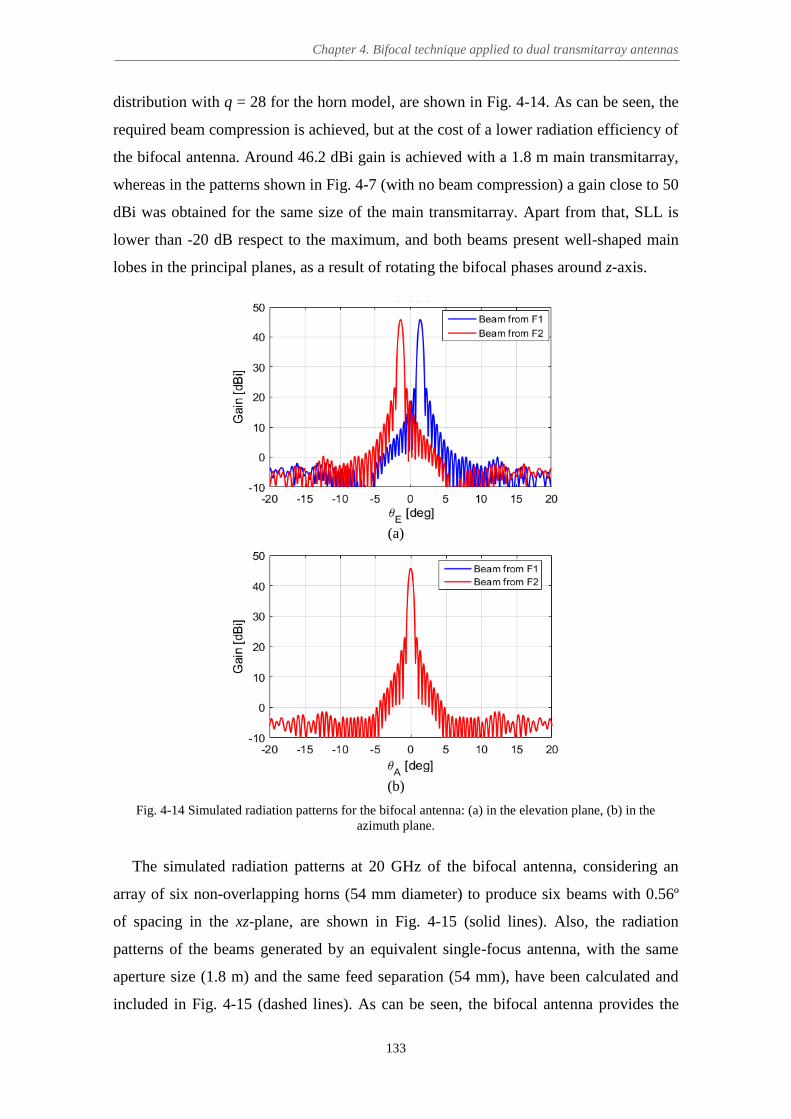
Chapter 4. Bifocal technique applied to dual transmitarray antennas
133
distribution with q = 28 for the horn model, are shown in Fig. 4-14. As can be seen, the
required beam compression is achieved, but at the cost of a lower radiation efficiency of
the bifocal antenna. Around 46.2 dBi gain is achieved with a 1.8 m main transmitarray,
whereas in the patterns shown in Fig. 4-7 (with no beam compression) a gain close to 50
dBi was obtained for the same size of the main transmitarray. Apart from that, SLL is
lower than -20 dB respect to the maximum, and both beams present well-shaped main
lobes in the principal planes, as a result of rotating the bifocal phases around z-axis.
(a)
(b)
Fig. 4-14 Simulated radiation patterns for the bifocal antenna: (a) in the elevation plane, (b) in the azimuth plane.
The simulated radiation patterns at 20 GHz of the bifocal antenna, considering an
array of six non-overlapping horns (54 mm diameter) to produce six beams with 0.56º
of spacing in the xz-plane, are shown in Fig. 4-15 (solid lines). Also, the radiation
patterns of the beams generated by an equivalent single-focus antenna, with the same
aperture size (1.8 m) and the same feed separation (54 mm), have been calculated and
included in Fig. 4-15 (dashed lines). As can be seen, the bifocal antenna provides the

Eduardo María Martínez de Rioja del Nido Ph.D. Thesis
134
required 0.56º separation between adjacent beams, while the beams from the equivalent
single-focus antenna present around 1.1º separation. This means that the bifocal antenna
is able to compress the beam spacing by a factor of 2 with respect to the single-focus
case, which would require 50% feed overlap to provide the same beam separation.
However, the gain of the beams is 4.25 dB lower than in the single-focus design, despite
considering the same aperture size.
Fig. 4-15 Simulated radiation patterns at 20 GHz in the xz-plane for the bifocal antenna to provide 0.56º
separation between beams (continuos lines) compared with the patterns for a monofocal equivalent antenna (dashed lines).
This reduction in the radiation efficiency is due to the high spillover on the first
transmitarray, whose size is smaller than required for an optimum illumination from the
feeds. The amplitude of the incident field over the symmetry axis of both transmitarrays
produced by the horns placed at F1 and F2 can be seen in Fig. 4-16. The solution to the
spillover problem is not trivial. If the first transmitarray is oversized to obtain -12 dB
taper, the illumination on the main transmitarray increases significantly and reaches
around -6 dB on the edges. Then, the main transmitarray should be also oversized, but
this would result in a diameter close to 4 m, which is twice the size that was initially
considered to provide 50 dBi gain at 20 GHz. Different dual transmitarray
configurations have been studied in order to obtain a high degree of beam spacing
compression, modifying the initial parameters of the bifocal synthesis, but the same
illumination problem remains.

Chapter 4. Bifocal technique applied to dual transmitarray antennas
135
Fig. 4-16 Amplitude (dB) of the incident field on the two transmitarrays produced by F1 and F2.
As an example, the bifocal algorithm has been executed with the initial parameters
that are summarized in Table 4-3. The geometry of the resulting dual transmitarray
antenna can be seen in Fig. 4-17, where D1 = 60 cm and D2 = 1.8 m. The reduction in
the size of the first transmitarray associated to the 1.8 m main transmitarray with respect
to the previous bifocal antenna (D1 = 1 m) is due to the performance of the bifocal
algorithm when the first transmitarray is moved towards the feeds, and constitutes the
main reason why the illumination problems will remain (despite of reducing SA
distance, which was intended to increase the subtended angle from the feeds on the first
transmitarray). The bifocal phase-shift distributions obtained for this design are shown
in Fig. 4-18. As can be seen, the use of shorter SA and larger SB distances provides
slightly smoother phase distributions than those shown in Fig. 4-13.
Fig. 4-17 Geometry of the dual transmitarray antenna to achieve beam compression.

Eduardo María Martínez de Rioja del Nido Ph.D. Thesis
136
(a) (b) Fig. 4-18 Bifocal phase-shift distributions (in degrees) obtained for: (a) the first transmitarray and (b) the
main transmitarray.
The simulated radiation patterns at 20 GHz in the principal planes for this bifocal
dual transmitarray antenna are presented in Fig. 4-19. The results are very similar to
those shown in Fig. 4-14; the maximum gain is close to 46 dB for the two beams
generated from the foci, while SLL is slightly higher than before (around -19 dB).
(a) (b)
Fig. 4-19 Simulated radiation patterns for the bifocal antenna: (a) in the elevation plane, (b) in the azimuth plane.
TABLE 4-3
INITIAL PARAMETERS OF THE BIFOCAL SYNTHESIS
Parameter Value
SA 2 m SB 0.75 m d 0.27 m
θb1 +1.4º θb2 -1.4º

Chapter 4. Bifocal technique applied to dual transmitarray antennas
137
The reason for this reduction in the radiation efficiency of the bifocal antenna, as in
the previous DTA configuration, are the high levels of illumination on the first
transmitarray, which has to be oversized in order to reduce spillover. However, this
modification leads to an increase of the illumination levels on the main transmitarray,
which has to be also oversized (a diameter of around 4 m is required to reach around -12
dB taper on the edges). Therefore, the bifocal antenna is able to provide a high degree of
beam spacing compression (by a factor of 2), but price to be paid is always the
reduction in the radiation efficiency, as in the case of the bifocal dual reflectarray
configuration that was shown in section 3.4.1.
4.5 Conclusions
The bifocal technique has been applied to dual transmitarray configurations for the
design of multi-beam antennas in Ka-band. The design with transmitarrays brings some
advantages, such as lower sensitivity to deformations and absence of blockage from the
feeds or the first transmitting structure. The latter factor allows for the use of centered
and rotationally-symmetrical geometries with a focal ring, which considerably
simplifies the design process (no further adjustments are required after rotating the 2D
design performed in the offset plane).
Two variations of the same baseline dual transmitarray geometry have been studied,
in order to facilitate the practical implementation of such an antenna (integration of the
feeds and the first transmitarray into the same sub-system, and holding of both
transmitarrays by the same supporting structure). The variations in the dimensions and
the required phase distributions for the dual transmitarray configurations have been
evaluated in this chapter.
Although the design of bifocal dual transmitarray antennas allows for a high degree
of beam spacing reduction, it presents the same efficiency problem than in the case of
dual reflectarrays. The results of the simulations for a bifocal dual transmitarray antenna
with a 1.8 m main transmitarray show that it is possible to achieve a high degree of
beam spacing compression (by a factor of 2) with respect to the equivalent monofocal
system, but at the cost of a reduced radiation efficiency. To increase the antenna
efficiency for this degree of beam compression, the main transmitarray should be
drastically oversized (around 4 m in diameter) to avoid spillover losses.

138

139
Chapter 5
General tridimensional bifocal method for dual reflectarray
configurations
5.1 Introduction
The bifocal technique presented in Chapter 3 allows to overcome the problem of the
3D design of dual reflectarray configurations by rotation of a 2D design performed in
the offset plane, considering an axially-symmetrical geometry with parallel reflectarrays
and following an analogous approach to that used for the design of bifocal dual
reflectors [80]. Then, the tilting of both reflectarrays was proposed in Chapter 3 to
obtain smoother phase distributions. A novel phase correction routine was implemented
to compensate the tilt of the reflectarrays and keep the bifocal characteristic of the
original design, providing reasonable results for the radiation patterns of the bifocal
antenna.
On the other hand, the technique proposed in Chapter 3 presents some limitations
that may discourage its use for certain DRA geometries. First, the technique works if
the relative tilt between the two reflectarrays is not very large. Also, it imposes some
geometrical restrictions in the initial positions of the foci and the reflectarrays that
remain throughout the design process of the bifocal antenna. These factors preclude the
design of highly offset DRA configurations (as the compact-range geometry shown in
[71]), which demand the implementation of a more general bifocal design procedure,
valid for any possible arrangement of the foci and the two reflectarrays.
In this chapter, a general 3D bifocal technique is proposed for the design of dual
reflectarray antennas, which makes it possible the direct synthesis of the phase

Eduardo María Martínez de Rioja del Nido Ph.D. Thesis
140
distributions in the selected antenna configuration, without geometrical constraints.
First, the proposed bifocal method is validated for the axially-symmetrical geometry
shown in section 3.2. Then, it is used to design a multi-beam dual reflectarray antenna
in an offset compact-range configuration for operation in transmission in Ka-band. The
phase distributions and radiation patterns of the bifocal antenna are studied for three
different design cases (low beam spacing compression, high beam spacing compression
and no beam spacing compression), and compared with those provided by the
equivalent monofocal antenna. Also, the capabilities of the bifocal technique to provide
a better multi-beam performance and a closer separation between adjacent beams are
evaluated in the three cases. Although the results in this chapter are presented only for
transmit antennas in Ka-band, the use of appropriate reflectarray cells that provide
independent phase-shifts at 20 and 30 GHz will allow for the design of Tx and Rx
antennas, with separate bifocal design processes for each frequency band.
5.2 Bifocal method for 3D design of dual reflectarray antennas
The implementation of a bifocal design method in 3D obliges to consider each
reflectarray as a planar surface, which will be characterized by the partial derivatives of
its phase distribution (Φ) with respect to the horizontal (y) and vertical (x) coordinates,
according to the reference system of each reflectarray shown in Fig. 5-1. From the study
of the reflecting properties of reflectarrays, it can be deduced that the partial derivatives
of the phase at each reflectarray cell will satisfy the following relations with the
incidence angles (θi, φi) and the reflection angles (θo, φo) of the rays [127]:
Φ′𝑥 =𝜕Φ(𝑥, 𝑦)
𝜕𝑥 =
2𝜋
𝜆· (sin 𝜃𝑖 cos𝜑𝑖 − sin 𝜃𝑜 cos𝜑𝑜) (5-1)
Φ′𝑦 =𝜕Φ(𝑥, 𝑦)
𝜕𝑦=
2𝜋
𝜆· (sin 𝜃𝑖 sin 𝜑𝑖 − sin 𝜃𝑜 sin𝜑𝑜) (5-2)
The previous expressions can be considered as the 3D extension of eq. (3-1), which
was introduced in Chapter 3 for a 2D system. These expressions will provide upper and
lower limits for the value of both partial phase derivatives, Φ’x and Φ’y, at each
reflectarray cell, since they depend on sine and cosine functions of the incidence and
reflection angles.

Chapter 5. General tridimensional bifocal method for dual reflectarray configurations
141
Concerning the geometry of the DRA system, it can be defined by the placement of
the two reflectarrays (in parallel planes, with a certain tilting, etc.), the location of the
focal points and the directions of the radiated beams associated to the foci. In this case,
it will be assumed that the foci (F1 and F2) and their associated beam directions (θ1 and
θ2) are both contained in the xz-plane (see Fig. 5-1), which will be the symmetry plane
(or offset plane) of the DRA configuration.
Fig. 5-1 Geometry of an offset DRA configuration with tilted reflectarrays in the xz-plane, including the first iteration of the bifocal ray-tracing routine.
The geometrical parameters of the bifocal antenna must be fixed before starting the
design procedure, according to the antenna specifications for the intended application. A
reference single-focus design (dual reflector or dual reflectarray antenna) can be also
used to estimate the dimensions of the bifocal antenna, at least as a first approximation.
As was explained in Chapter 3, setting very stringent or improper initial conditions may
lead to convergence problems of the bifocal algorithm, not being possible to reach a
valid solution for the design of the bifocal antenna with such characteristics.

Eduardo María Martínez de Rioja del Nido Ph.D. Thesis
142
The partial phase derivatives Φ’x and Φ’y will be determined for a discrete grid of
points on the surface of each reflectarray, by means of an iterative 3D ray-tracing
routine that makes use of eqs. (5-1) and (5-2) and follows a similar procedure than in
the bifocal design of dual reflectors [81]. The ray-tracing routine will be executed
several times: each execution will provide a column of points on the surface of each
reflectarray, and the addition of adjacent columns will form a grid. Then, the samples of
the phase derivatives will be interpolated and properly integrated to obtain the required
bifocal phase distributions on both reflectarrays. A block diagram with the steps of the
proposed 3D bifocal design method is presented in Fig. 5-2. The different steps of the
bifocal algorithm will be described in the following sections.
Fig. 5-2 Steps of the 3D bifocal design procedure.

Chapter 5. General tridimensional bifocal method for dual reflectarray configurations
143
5.2.1 Ray tracing procedure
The 3D ray-tracing routine can be executed several times, until obtaining a sufficient
number of points to characterize each reflectarray. Each execution ‘n’ (with 1 ≤ n ≤ N)
requires an initial point on the sub-reflectarray plane, S1n, and the values of the partial
phase derivatives associated to that point, Φ’x(S1n) and Φ’y(S1
n). To ensure an efficient
performance of the ray-tracing procedure, the points S1n must be located along the sub-
reflectarray cross section (in the direction of y-axis, according to Fig. 5-1).
A transmitted ray from focus F1 that impinges on S1n is reflected with angles (θo, φo),
which can be obtained by applying (5-1) and (5-2) at S1n. The reflected ray provides a
new point on the main reflectarray, M1n, whose partial phase derivatives Φ’x(M1
n) and
Φ’y(M1n) are calculated by applying (5-1) and (5-2) at M1
n with output angles (θ1, 0º).
Similarly, a received ray in the direction (θ2, 0º) that impinges on M1n provides a new
point on the sub-reflectarray, S2n, and its phase derivatives, Φ’x(S2
n) and Φ’y(S2n), by
applying (5-1) and (5-2) first at M1n, and then at S2
n. The previous steps can be repeated
starting with a transmitted ray from F1 that impinges on S2n; after M iterations, a row of
M points is obtained on the surface of the main reflectarray, while M+1 points are
achieved on the sub-reflectarray in a similar linear arrangement. In the end, the
execution of the 3D ray-tracing routine N times will provide a grid of N·M points that
characterize the main reflectarray, and N·(M+1) points for the sub-reflectarray. A flow
chart summarizing the main steps of the 3D ray-tracing routine is shown in Fig. 5-3.
Due to the system’s symmetry with respect to the xz-plane, the 3D ray-tracing
process can be performed only in the y ≥ 0 region, and then the resulting points can be
replicated in the other half-space (y < 0). For this purpose, note that the partial
derivative Φ’x will present even symmetry with respect to the xz-plane, while Φ’y will
present odd symmetry:
Φ′𝑥(𝑥𝑠, −𝑦𝑠) = Φ′𝑥(𝑥𝑠, 𝑦𝑠) (5-3)
Φ′𝑦(𝑥𝑠, −𝑦𝑠) = −Φ′𝑦(𝑥𝑠, 𝑦𝑠) (5-4)
As an example of the results that can be achieved, Fig. 5-4 shows the grids of points
obtained for a DRA system with parallel reflectarrays (the results correspond to the
DRA geometry analyzed in section 5.3). The samples of the normalized partial phase
derivatives (multiplied by -λ/2π) associated to this geometry are shown in Fig. 5-5 for
both sub- and main reflectarrays.

Eduardo María Martínez de Rioja del Nido Ph.D. Thesis
144
Fig. 5-3 Flow chart with the steps of the 3D ray-tracing procedure.
Starting point for column n:
S1
n with {Φ’x(S1
n), Φ’y(S1
n)}
A transmitted ray from F1 impinges on Si
n and is
reflected towards the main reflectarray
The ray impinges on Mi
n and is reflected
with an angle θb1
The ray impinges on Si+1
n and is reflected
towards F2
A received ray in the direction θb2 impinges on Mi
n
and is reflected towards the sub-reflectarray
New point Mi
n
New point Si+1
i = 1
i = i + 1 (next point in column n)
i ≤ M
no
yes
Phase derivatives {Φ’x(Mi
n), Φ’y(Mi
n)}
Phase derivatives {Φ’x(Si+1
n), Φ’y(Si+1
n)}
n = n + 1 (next column)
yes
no
n ≤ N
A set of phase derivative samples is obtained for each reflectarray:
{Φ’x(Si
n), Φ’y(Si
n)} and {Φ’x(Mi
n), Φ’y(Mi
n)}
n = 1
Geometrical parameters of the DRA

Chapter 5. General tridimensional bifocal method for dual reflectarray configurations
145
Fig. 5-4 Example of the grid of points obtained for each reflectarray after executing the 3D bifocal ray-tracing routine.
(a) (b)
(c) (d)
Fig. 5-5 Samples of the phase derivative: on the sub-reflectarray for (a) ∂Φ/∂x and (b) ∂Φ/∂y, and on the
main reflectarray for (c) ∂Φ/∂x and (d) ∂Φ/∂y.

Eduardo María Martínez de Rioja del Nido Ph.D. Thesis
146
5.2.2 Setting of the initial values for the phase derivatives
There are several options to determine the value of the partial phase derivatives at the
starting points of the 3D bifocal algorithm (S1n, with 1 ≤ n ≤ N), so that the resulting
phases make sense. In the more general case in which the DRA configuration does not
present axial symmetry, as in the offset compact range geometry shown in [71], the
equivalent single-focus design (considering the middle point between F1 and F2 as the
new focus) can be used to fix the initial conditions for the 3D bifocal algorithm. The
monofocal phase distributions can be calculated as described in [128], and then,
differentiated with respect to x and y variables. The values of Ф’x and Ф’y for those
points at the lower horizontal section of the sub-reflectarray can be used as initial
conditions to start each execution of the 3D bifocal algorithm (see section 5.4). The
phase derivatives from the single-focus design will ensure that the beams are collimated
in the azimuth plane, while the bifocal synthesis will be responsible for shaping and
pointing the beams in elevation (xz-plane).
In a rotationally-symmetrical configuration, where the two reflectarrays are parallel
to the xy-plane and the position of the foci and the beam directions are symmetrical with
respect to z-axis, the values of Ф’x and Ф’y at the starting points S1n can be determined
from the samples obtained after the first execution of the bifocal ray-tracing routine in
the xz-plane. In that case, the algorithm starts at the point S1 = (0, 0, z0) on the vertical
axis of the sub-reflectarray (placed at the plane z = z0), with both Φ’x and Φ’y equal to
zero (due to the axial symmetry conditions, as explained in section 3.2.1). After several
iterations of the ray tracing, a set of points Si1 = (xi, 0, z0) is obtained along the vertical
axis of the sub-reflectarray, with partial phase derivatives (Ф’xi, 0). Note that Ф’y will be
null at the points Si1, since it is an odd function with respect to y. Then, a set of points
S1i = (0, yi, z0) placed along the horizontal axis which results from the intersection of the
planes x = 0 and z = z0 (thus being parallel to y-axis) is attained by rotating 90º around z-
axis the points Si1 obtained in the xz-plane. The points S1
i are chosen as starting points at
the plane x = 0 for the bifocal ray-tracing routine; the values of the phase derivatives
associated to these points are obtained by applying the rotation symmetry properties:
Φ′𝑥(0, 𝑦𝑖) = Φ′𝑦(𝑥𝑖, 0) |𝑦𝑖=𝑥𝑖= 0 (5-5)
Φ′𝑦(0, 𝑦𝑖) = Φ′𝑥(𝑥𝑖, 0) |𝑦𝑖=𝑥𝑖= Φ′𝑥𝑖 (5-6)

Chapter 5. General tridimensional bifocal method for dual reflectarray configurations
147
The starting points S1i obtained by this method correspond to the direction of the
positive y-axis, but additional points can be obtained along the negative y-axis by
applying (5-3) and (5-4), which allows to double the number of starting points by
exploiting the symmetry conditions of both partial phase derivatives. Moreover, note
that the points S1i placed at the plane x = 0 are used to start each execution of the bifocal
ray-tracing routine, but the points selected to constitute the first row of the sub-
reflectarray (its lower horizontal section) may be located at x = x0 > 0, as in the
Cassegrain design shown in section 3.2.
5.2.3 Integration of the partial phase derivatives
Once the phase derivatives samples are obtained on the surface of both reflectarrays,
Φ’x and Φ’y must be interpolated by polynomials depending on x and y variables. Then,
each partial derivative will be integrated with respect to x or y:
∫Φ′𝑥(𝑥, 𝑦) 𝑑𝑥 = 𝑓(𝑥, 𝑦) + 𝐶1(𝑦) (5-7)
∫Φ′𝑦(𝑥, 𝑦) 𝑑𝑦 = 𝑔(𝑥, 𝑦) + 𝐶2(𝑥) (5-8)
where C1(y) and C2(x) are the integration constants, which are polynomials of y and x,
respectively. If the bifocal technique has been correctly applied and appropriate
polynomials are selected for the interpolation of Φ’x and Φ’y, the terms of the form xp·yq
will present the same coefficients in f(x, y) and g(x, y). Then, f(x, y) may contain some
terms of the form xp, while g(x, y) may contain some terms in yq. The correct expression
for the phase Φ(x, y) is a combination of the two partial integrals including the common
terms and those depending on xp and yq, which can be expressed as:
Φ(𝑥, 𝑦) = 𝑓(𝑥, 𝑦) + 𝑔(0, 𝑦) = 𝑓(𝑥, 0) + 𝑔(𝑥, 𝑦) (5-9)
As an example, the unwrapped bifocal phase functions (in degrees) obtained for each
reflectarray after the integration of the partial phase derivatives shown in Fig. 5-5 can be
seen in Fig. 5-6. Note that the relation between the point distributions obtained in the
bifocal synthesis for each reflectarray can be used to estimate the appropriate
dimensions of both reflecting surfaces. The illumination will be concentrated in the
regions where the points are very close one to each other, and therefore these regions
should be included in the antenna to avoid a high spillover.

Eduardo María Martínez de Rioja del Nido Ph.D. Thesis
148
(a)
(b)
Fig. 5-6 Example of unwrapped bifocal phase distributions obtained for: (a) the sub-reflectarray and (b) the main reflectarray.
5.3 Validation in an axially symmetrical geometry
The 3D bifocal algorithm has been applied to the DRA geometry shown in section
3.2, which is an example of an axially-symmetrical configuration where the two
reflectarrays are parallel to the xy-plane and the positions of the foci and beam
directions are symmetrical with respect to z-axis (see Fig. 5-7). The two conjugate focal
locations are: F1 = (-0.1, 0, 1) m and F2 = (0.1, 0, 1) m. The directions of the beams
associated to the foci are: (θ1 = 1.5º, φ1 = 0º) and (θ2 = -1.5º, φ2 = 0º). The diameter of
the main reflectarray is 1.8 m, and the position of its geometrical center in the reference
coordinate system shown in Fig. 5-7 is CM = (1.7, 0, 0) m. The diameter of the sub-
reflectarray is 60 cm and its center is located at CS = (0.5, 0, 1.5) m.
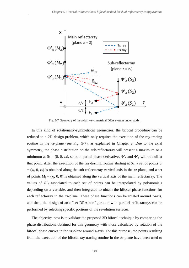
Chapter 5. General tridimensional bifocal method for dual reflectarray configurations
149
Fig. 5-7 Geometry of the axially-symmetrical DRA system under study.
In this kind of rotationally-symmetrical geometries, the bifocal procedure can be
reduced to a 2D design problem, which only requires the execution of the ray-tracing
routine in the xz-plane (see Fig. 5-7), as explained in Chapter 3. Due to the axial
symmetry, the phase distribution on the sub-reflectarray will present a maximum or a
minimum at S1 = (0, 0, z0), so both partial phase derivatives Φ’x and Φ’y will be null at
that point. After the execution of the ray-tracing routine starting at S1, a set of points Si
= (xi, 0, z0) is obtained along the sub-reflectarray vertical axis in the xz-plane, and a set
of points Mj = (xj, 0, 0) is obtained along the vertical axis of the main reflectarray. The
values of Φ’x associated to each set of points can be interpolated by polynomials
depending on x variable, and then integrated to obtain the bifocal phase functions for
each reflectarray in the xz-plane. These phase functions can be rotated around z-axis,
and then, the design of an offset DRA configuration with parallel reflectarrays can be
performed by selecting specific portions of the revolution surfaces.
The objective now is to validate the proposed 3D bifocal technique by comparing the
phase distributions obtained for this geometry with those calculated by rotation of the
bifocal phase curves in the xz-plane around z-axis. For this purpose, the points resulting
from the execution of the bifocal ray-tracing routine in the xz-plane have been used to

Eduardo María Martínez de Rioja del Nido Ph.D. Thesis
150
obtain by a 90º rotation the starting points S1n = (0, yn, z0), placed along the horizontal
axis resulting from the intersection of the planes x = 0 and z = z0 (which is also parallel
to y-axis), as explained in section 5.2.2. Figure 5-8 shows the normalized values of Ф’x
and Ф’y at the points S1n with respect to y coordinate. Note that Ф’x is equal to zero for
all points, while Ф’y is an odd function.
Fig. 5-8 Normalized phase derivatives on the lower horizontal section of the sub-reflectarray, used as
initial conditions for the 3D bifocal algorithm.
The grids of points obtained for each reflectarray, as well as the samples of the
normalized phase derivatives corresponding to this DRA geometry have been shown in
Fig. 5-4 and Fig. 5-5, respectively. The phase derivative samples have been interpolated
using 9-degree polynomials and then integrated. The resulting bifocal phase functions
have been shown in Fig. 5-6. The final phase-shift distributions corresponding to the 60-
cm sub-reflectarray and the 1.8-m main reflectarray are presented in Fig. 5-9,
normalized between -360º and 0º.
(a) (b) Fig. 5-9 Bifocal phase-shift distributions (in degrees) obtained by the 3D algorithm for: (a) the sub-
reflectarray and (b) the main reflectarray.

Chapter 5. General tridimensional bifocal method for dual reflectarray configurations
151
(a) (b)
Fig. 5-10 Difference (in degrees) between the phases obtained by the 3D algorithm and by the 2D algorithm with rotation of phase curves: (a) on the sub-reflectarray and (b) main reflectarray.
The difference between the phases obtained by the 3D bifocal method and those
obtained by rotation of the 2D bifocal phase curves in the xz-plane is shown in Fig.
5-10. As can be seen, this difference is lower than 1.2º for the main-reflectarray
elements, while in the sub-reflectarray this difference is equal to 2º in the worst case (in
the majority of the sub-reflectarray elements, it is below 1º). Therefore, the difference
between the two methods is almost negligible and can be attributed to the accuracy of
the mathematical procedures involved in the synthesis of the bifocal phases. For
example, this error could be reduced by using higher degree polynomials for the
interpolation of the phase derivatives. In any case, the phase errors produced in the
implementation of the phase with real reflectarray cells, or the manufacturing errors,
will be larger than 2º (at least 10º).
The comparison of the simulated radiation patterns at 20 GHz in the principal planes
for the two beams generated by the foci of the bifocal antenna are shown in Fig. 5-11
and Fig. 5-12. Note that the cross-polar radiation is not represented in the figures,
because the radiation patterns have been computed assuming ideal reflectarray cells.
The difference in the phases obtained by the two bifocal methods has virtually no effect
on the radiation patterns, which present a very good agreement. These results prove the
validity of the proposed 3D bifocal technique in a rotationally-symmetrical DRA
configuration.

Eduardo María Martínez de Rioja del Nido Ph.D. Thesis
152
Fig. 5-11 Comparison of the simulated radiation patterns in the xz-plane for the 3D bifocal algorithm and
the 2D algorithm with rotation of phase curves.
(a)
(b)
Fig. 5-12 Comparison of the simulated radiation patterns in the azimuth plane (orthogonal plane in the beam direction) for the 3D bifocal algorithm and the 2D algorithm with rotation of phase curves: (a) for
the beam produced from F1 (θ1 = 1.5º), and (b) for the beam produced from F2 (θ2 = -1.5º).

Chapter 5. General tridimensional bifocal method for dual reflectarray configurations
153
5.4 Design of a multi-beam satellite antenna in Ka-band
The 3D bifocal technique has been applied to the offset compact-range configuration
shown in Fig. 5-13, whose main geometrical parameters are summarized in Table 5-1,
in order to design a multi-beam satellite antenna for operation in the Ka-band transmit
frequencies. The antenna geometry has been adjusted to avoid blockage from the feeds
or the sub-reflectarray. The period of the main reflectarray (main-RA) cells is 7.5 mm,
while a 10 mm period has been used for the sub-reflectarray (sub-RA). The lack of axial
symmetry and the large tilt angle of the sub-reflectarray with respect to the main
reflectarray prevent from the application of the bifocal procedure presented in Chapter
3. Therefore, the synthesis of the required phase distributions on each reflectarray will
be carried out by the 3D bifocal method proposed in section 5.2.
Fig. 5-13 Geometry of the compact-range DRA system under study.
TABLE 5-1
MAIN GEOMETRICAL PARAMETERS OF THE COMPACT-RANGE SYSTEM
Parameter Value
Size Main-RA 1.80 x 1.59 m (240 x 212 elements)
Size Sub-RA 1.31 x 1.23 m (131 x 123 elements)
Angle of tilting Sub-RA 47.55º
Coordinates center Main-RA [0, 0, 0] mm
Coordinates center Sub-RA [-644, 0, 1017] mm
Phase center F1 (focus 1 BDRA) [208, 0, 1108] mm
Phase center F5 (focus 2 BDRA) [412, 0, 1192] mm
Distance F1-F5 216 mm
Phase center F3 (focus MDRA) [310, 0, 1150] mm
Virtual focus related to F3 [-2546, 0, 4721] mm

Eduardo María Martínez de Rioja del Nido Ph.D. Thesis
154
A linear arrangement of 7 adjacent feeds, from F0 to F6, has been considered. The
feed-horns present the same characteristics than those used in Chapter 3 (a realistic feed
model characterized by Astrium [82] has been used as a reference). They have 54 mm
diameter and provide -12 dB illumination on the sub-reflectarray edges at 20 GHz when
the sub-reflectarray is illuminated with a subtended angle of 36º from the feed.
Prior to the design of the bifocal antenna, a single-focus reference design has been
performed at 19.7 GHz for the central feed, F3, to radiate at (θ3 = 28º, φ3 = 0º) with
respect to the normal vector to the main reflectarray surface (see Fig. 5-13). The
required phase-shift distributions for this monofocal dual reflectarray antenna (MDRA)
have been obtained by the method described in [128] and are shown in Fig. 5-14.
(a) (b)
Fig. 5-14 Monofocal phase distributions (in degrees) required on the: (a) sub-reflectarray and (b) main reflectarray.
5.4.1 Bifocal antenna with small beam spacing compression
The 3D bifocal algorithm has been used to synthesize the phases on the two
reflectarrays, considering the phase centers of the feeds F1 and F5 as the foci of the
bifocal dual reflectarray antenna (BDRA), which will generate two beams at 19.7 GHz
in the directions (θ1 = 30.24º, φ1 = 0º) and (θ5 = 25.76º, φ5 = 0º). The designed BDRA
will provide a separation of 1.12º between beams generated by contiguous feeds,
whereas the equivalent MDRA will provide around 1.24º of beam spacing (as will be
shown latter, see Fig. 5-22). This means that the BDRA will compress the beams by a
factor of 1.24º/1.12º = 1.11.
Due to the non-rotationally symmetrical geometry of the DRA system, the phase
distribution on the sub-reflectarray in the equivalent MDRA has been used to compute

Chapter 5. General tridimensional bifocal method for dual reflectarray configurations
155
the value of the partial phase derivatives on its lower horizontal section (parallel to y-
axis), in order to provide a set of starting points for the 3D bifocal algorithm. The
phase-shift distribution shown in Fig. 5-14(a) has been extended to consider a
rectangular sub-reflectarray of size 1.31 x 1.23 m instead of a slightly elliptical one (see
Fig. 5-15), so as to increase the number of elements in the first row of the sub-
reflectarray. Then, the unwrapped monofocal phases have been differentiated with
respect to x and y variables.
Fig. 5-15 Monofocal phase-shift distribution (in degrees) on the rectangular sub-reflectarray.
Figure 5-16 shows the normalized curves obtained for Ф’x and Ф’y with respect to y
coordinate at the lower horizontal section of the sub-reflectarray. Note that Ф’x presents
even symmetry and Ф’y is an odd function. A constant γ0 = -0.123 has been previously
added to the normalized Ф’x curve so that its maximum is now Ф’x (y = 0) = 0. This
adjustment does not affect the performance of the bifocal procedure, since the shape of
the Ф’x curve remains the same, but it allows to reduce the number of 360º cycles in the
resulting phase-shift distributions (as will be shown later).
Fig. 5-16 Normalized phase derivatives on the lower horizontal section of the sub-reflectarray, used as
initial conditions for the 3D algorithm.

Eduardo María Martínez de Rioja del Nido Ph.D. Thesis
156
Fig. 5-17 Grid of points obtained for each reflectarray after executing the 3D bifocal ray-tracing routine.
(a) (b)
(c) (d)
Fig. 5-18 Samples of the phase derivative: on the sub-reflectarray for (a) ∂Φ/∂x and (b) ∂Φ/∂y, and on the
main reflectarray for (c) ∂Φ/∂x and (d) ∂Φ/∂y.

Chapter 5. General tridimensional bifocal method for dual reflectarray configurations
157
The grids of points obtained for the two reflectarrays after applying the ray-tracing
routine to the current geometry can be seen in Fig. 5-17. The samples of the partial
phase derivatives associated to each reflectarray are shown in Fig. 5-18. The unwrapped
phase functions that arise from the interpolation and integration of the phase derivatives
are shown in Fig. 5-19, and the final bifocal phase-shift distributions to be implemented
on each reflectarray (normalized between -360º and 0º) are shown in Fig. 5-20.
(a) (b)
Fig. 5-19 Unwrapped bifocal phase functions obtained for the: (a) sub-reflectarray and (b) main reflectarray.
(a) (b)
Fig. 5-20 Bifocal phase distributions (in degrees) required on the: (a) sub-reflectarray and (b) main reflectarray.
The DRA system has been analyzed by applying the modular technique described in
[70] and assuming ideal reflectarray cells in both surfaces. A cosq(θ) model with q = 28
has been used to simulate the electromagnetic field radiated by the 54-mm horns. The
simulated radiation patterns of the seven beams produced by the BDRA at 19.7 GHz in
elevation (xz-plane) and azimuth (orthogonal plane in the direction of the beam) are
shown in Fig. 5-21. The maximum gain varies from 47.6 dBi to 47.85 dBi, and side-
lobe levels are lower than -23 dB for all the beams.

Eduardo María Martínez de Rioja del Nido Ph.D. Thesis
158
(a)
(b) Fig. 5-21 Simulated radiation patterns for the BDRA to provide 1.12º of beam spacing at 19.7 GHz: (a)
superposition of cuts in the azimuth plane, and (b) cut in the xz-plane.
Moreover, Fig. 5-22 shows the comparison of the radiation patterns in the xz-plane
for the beams generated by the BDRA (solid lines) and those produced by the
equivalent MDRA (dashed lines). As can be seen, the BDRA provides a better
performance for the extreme beams (around 0.45 dB larger gain and 3 dB lower SLL),
while reducing at the same time the beam spacing in the xz-plane from 1.24º to 1.12º.
So, beam spacing is compressed by a factor of 1.24º/1.12º = 1.11 with respect to the
MDRA for the same feed spacing. These results reinforce the validity of the proposed
3D bifocal technique when applied to non-rotationally symmetrical geometries, as well
as its main advantages over the equivalent monofocal design.
The amplitude distributions of the incident electric field on both reflectarrays
produced by the two feeds placed at the foci of the BDRA (F1 and F5) are shown in Fig.
5-23. The module of the incident field is close to -12 dB on the edges of both
reflectarrays and the estimated radiation efficiency is around 55%, considering the
expected gain from an elliptical aperture of 1.8 x 1.59 m.

Chapter 5. General tridimensional bifocal method for dual reflectarray configurations
159
Fig. 5-22 Simulated radiation patterns at 19.7 GHz in the xz-plane for the beams produced by the BDRA
(solid lines) and by the MDRA (dashed lines).
(a) (b)
(c) (d)
Fig. 5-23 Amplitude (dB) of the incident field on the sub-reflectarray when the antenna is illuminated from (a) F1 and (b) F5, and on the main reflectarray for illumination from (c) F1 and (d) F5.
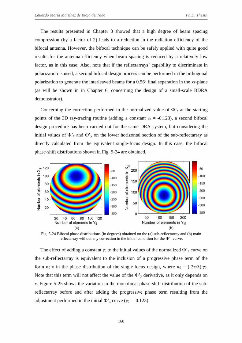
Eduardo María Martínez de Rioja del Nido Ph.D. Thesis
160
The results presented in Chapter 3 showed that a high degree of beam spacing
compression (by a factor of 2) leads to a reduction in the radiation efficiency of the
bifocal antenna. However, the bifocal technique can be safely applied with quite good
results for the antenna efficiency when beam spacing is reduced by a relatively low
factor, as in this case. Also, note that if the reflectarrays’ capability to discriminate in
polarization is used, a second bifocal design process can be performed in the orthogonal
polarization to generate the interleaved beams for a 0.56º final separation in the xz-plane
(as will be shown in in Chapter 6, concerning the design of a small-scale BDRA
demonstrator).
Concerning the correction performed in the normalized value of Ф’x at the starting
points of the 3D ray-tracing routine (adding a constant γ0 = -0.123), a second bifocal
design procedure has been carried out for the same DRA system, but considering the
initial values of Ф’x and Ф’y on the lower horizontal section of the sub-reflectarray as
directly calculated from the equivalent single-focus design. In this case, the bifocal
phase-shift distributions shown in Fig. 5-24 are obtained.
(a) (b)
Fig. 5-24 Bifocal phase distributions (in degrees) obtained on the (a) sub-reflectarray and (b) main reflectarray without any correction in the initial condition for the Ф’x curve.
The effect of adding a constant γ0 to the initial values of the normalized Ф’x curve on
the sub-reflectarray is equivalent to the inclusion of a progressive phase term of the
form α0·x in the phase distribution of the single-focus design, where α0 = (-2π/λ)·γ0.
Note that this term will not affect the value of the Ф’y derivative, as it only depends on
x. Figure 5-25 shows the variation in the monofocal phase-shift distribution of the sub-
reflectarray before and after adding the progressive phase term resulting from the
adjustment performed in the initial Ф’x curve (γ0 = -0.123).

Chapter 5. General tridimensional bifocal method for dual reflectarray configurations
161
(a) (b)
Fig. 5-25 Phase-shift distributions (in degrees) on the sub-reflectarray for the reference monofocal antenna: (a) in the original monofocal design, and (b) after adding a progressive phase term.
The progressive phase term added to the phase distribution of the sub-reflectarray
would produce a shifting in the directions of the radiated beams; however, the bifocal
algorithm is able to compensate this variation in the sub-reflectarray phases by adding a
progressive phase term of opposite sign in the phase distribution of the main
reflectarray. This fact can be checked by subtracting the phase-shift distributions shown
in Fig. 5-20 (with the corrected Ф’x curve, γ0 = -0.123) to those shown in Fig. 5-24 (with
Ф’x directly calculated from the single-focus reference design, γ0 = 0). The results can
be seen in Fig. 5-26.
(a) (b)
Fig. 5-26 Difference (in degrees) between the phase distributions with and without correcting the initial condition for the Ф’x curve: (a) on the sub-reflectarray, and (b) on the main reflectarray.
Furthermore, the simulated radiation patterns at 19.7 GHz in the xz-plane for the
second BDRA design (with the phase-shift distributions in Fig. 5-24) have been
obtained. The comparison with the patterns shown in Fig. 5-21 for the initial BDRA,
designed with the corrected Ф’x curve, is presented in Fig. 5-27.

Eduardo María Martínez de Rioja del Nido Ph.D. Thesis
162
Fig. 5-27 Comparison of the radiation patterns at 19.7 GHz in the xz-plane for the beams produced by the
BDRA with modified Ф’x curve (solid lines) and by the BDRA with original Ф’x curve (dashed lines).
Therefore, it can be concluded that the correction introduced in the value of the Ф’x
curve used as initial condition for the 3D bifocal algorithm allows to obtain more
centered phase distributions for both reflectarrays (meaning that the elements with the
smoothest phase variations are near to the geometrical centers of both reflectarrays),
without any effect on the radiation patterns of the bifocal antenna. It has been checked
that a larger value of γ0 causes a greater variation in the bifocal phase distributions with
respect to those calculated for γ0 = 0. However, note that the allowed values of γ0 will be
limited by the application of eq. (5-1) in the subsequent 3D ray-tracing procedure,
which fixes a limit for the value of Ф’x. These results are very interesting because they
help us to understand better the behavior of the bifocal algorithm.
5.4.2 Bifocal antenna with large beam spacing compression
To continue with the study of the bifocal technique, a new design has been
performed applying the 3D bifocal method for the same DRA configuration in order to
reduce the beam spacing to 0.56º (typical value for current multi-spot satellite
applications in Ka-band). The high ratio of beam spacing compression (BCR =
1.24º/0.56º = 2.21) will be responsible for the appearance of a larger number of 360º
cycles in the bifocal phase-shift distributions of both reflectarrays. This can be partially
corrected by adding a certain constant γ0 to the normalized Ф’x curve in the lower
horizontal section of the sub-reflectarray, as explained in the previous section. In this
case, the best results for the phase distributions are obtained with γ0 = -0.563 (see Fig.
5-28), which is the minimum allowed value for γ0. After this adjustment, the maximum

Chapter 5. General tridimensional bifocal method for dual reflectarray configurations
163
of the normalized Ф’x curve is Ф’x (y = 0) = -0.44, while the shape of the curve remains
the same than in Fig. 5-16.
(a) (b)
Fig. 5-28 Required phase-shift distributions (in degrees) for the bifocal antenna to provide 0.56º of beam spacing: (a) on the sub-reflectarray, and (b) on the main-reflectarray.
The simulated radiation patterns in the elevation and azimuth orthogonal planes for
this BDRA are shown in Fig. 5-29. The gain varies from 42.8 dBi to 44.5 dBi, and the
SLL is equal to or lower than -16 dB for all the beams. Despite achieving the required
beam compression (0.56º separation between adjacent beams), the antenna presents a
serious efficiency problem, which can be noticed in the reduced gain of the beams.
A comparison of the simulated radiation patterns at 19.7 GHz in the xz-plane for the
beams generated by the BDRA (solid lines) and those produced by the equivalent
MDRA (dashed lines) is shown in Fig. 5-30. As can be seen, the BDRA is able to
reduce beam spacing from 1.24º to 0.56º, so the beams are compressed by a factor of
1.24º/0.56º = 2.21 with respect to the MDRA. On the other hand, the beams from the
BDRA present around 3-4 dB lower gain than the beams from the MDRA (about 47.7
dBi gain), and SLL is between 6 and 7 dB higher than in the monofocal case.
The amplitude distributions of the incident field on both reflectarrays considering
illumination from F1 and F5 are shown in Fig. 5-31. Note that the illumination levels on
the edges of the main reflectarray are very high, which produces a lot of spillover, and
thus, a reduction in the radiation efficiency of the bifocal antenna. These results are
caused by the application of the bifocal technique for a high degree of beam spacing
compression (BCR = 2.21), which spreads the illumination along the vertical axis of the
main reflectarray (the direction in which the beams are compressed) with respect to the
amplitude distributions shown in Fig. 5-23 for the BDRA with BCR = 1.11.

Eduardo María Martínez de Rioja del Nido Ph.D. Thesis
164
(a)
(b)
Fig. 5-29 Simulated radiation patterns for the BDRA to provide 0.56º of beam spacing at 19.7 GHz: (a) superposition of cuts in the azimuth plane, and (b) cut in the xz-plane.
Fig. 5-30 Comparison of the radiation patterns in the xz-plane for beams generated at 19.7 GHz by the
BDRA (solid lines) and by the equivalent MDRA (dashed lines).

Chapter 5. General tridimensional bifocal method for dual reflectarray configurations
165
(a) (b)
(c) (d)
Fig. 5-31 Amplitude (dB) of the incident field on the sub-reflectarray for (a) F1 and (b) F5, and on the main reflectarray for (c) F1 and (d) F5.
As indicated in Chapter 3, introducing some modifications in the initial conditions of
the bifocal synthesis or changing the antenna configuration does not mitigate the
illumination problem. The only possible solution would be to increase the size of the
main reflectarray, which implies using a very large reflectarray, around 3.5 m in
diameter (twice its original size). However, enlarging the size of the main reflectarray in
the current geometry will produce blockage from the feeds (see Fig. 5-13). Therefore,
the antenna geometry should be modified to allow the implementation of a bifocal
antenna with an oversized main reflectarray, which will reduce spillover and increase
the radiation efficiency of the antenna (as will be shown in Chapter 7).
5.4.3 Bifocal antenna with no beam compression
A third bifocal design has been carried out in which the separation between adjacent
beams will be the same than in the single-focus reference design: 1.24º (so, BCR = 1).
The idea is to apply the bifocal algorithm to correct beam aberration and improve the
multi-beam performance with respect to the equivalent MDRA. In this design, the
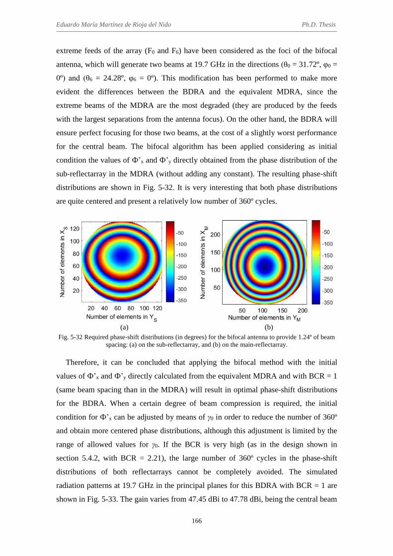
Eduardo María Martínez de Rioja del Nido Ph.D. Thesis
166
extreme feeds of the array (F0 and F6) have been considered as the foci of the bifocal
antenna, which will generate two beams at 19.7 GHz in the directions (θ0 = 31.72º, φ0 =
0º) and (θ6 = 24.28º, φ6 = 0º). This modification has been performed to make more
evident the differences between the BDRA and the equivalent MDRA, since the
extreme beams of the MDRA are the most degraded (they are produced by the feeds
with the largest separations from the antenna focus). On the other hand, the BDRA will
ensure perfect focusing for those two beams, at the cost of a slightly worst performance
for the central beam. The bifocal algorithm has been applied considering as initial
condition the values of Ф’x and Ф’y directly obtained from the phase distribution of the
sub-reflectarray in the MDRA (without adding any constant). The resulting phase-shift
distributions are shown in Fig. 5-32. It is very interesting that both phase distributions
are quite centered and present a relatively low number of 360º cycles.
(a) (b)
Fig. 5-32 Required phase-shift distributions (in degrees) for the bifocal antenna to provide 1.24º of beam spacing: (a) on the sub-reflectarray, and (b) on the main-reflectarray.
Therefore, it can be concluded that applying the bifocal method with the initial
values of Ф’x and Ф’y directly calculated from the equivalent MDRA and with BCR = 1
(same beam spacing than in the MDRA) will result in optimal phase-shift distributions
for the BDRA. When a certain degree of beam compression is required, the initial
condition for Ф’x can be adjusted by means of γ0 in order to reduce the number of 360º
and obtain more centered phase distributions, although this adjustment is limited by the
range of allowed values for γ0. If the BCR is very high (as in the design shown in
section 5.4.2, with BCR = 2.21), the large number of 360º cycles in the phase-shift
distributions of both reflectarrays cannot be completely avoided. The simulated
radiation patterns at 19.7 GHz in the principal planes for this BDRA with BCR = 1 are
shown in Fig. 5-33. The gain varies from 47.45 dBi to 47.78 dBi, being the central beam
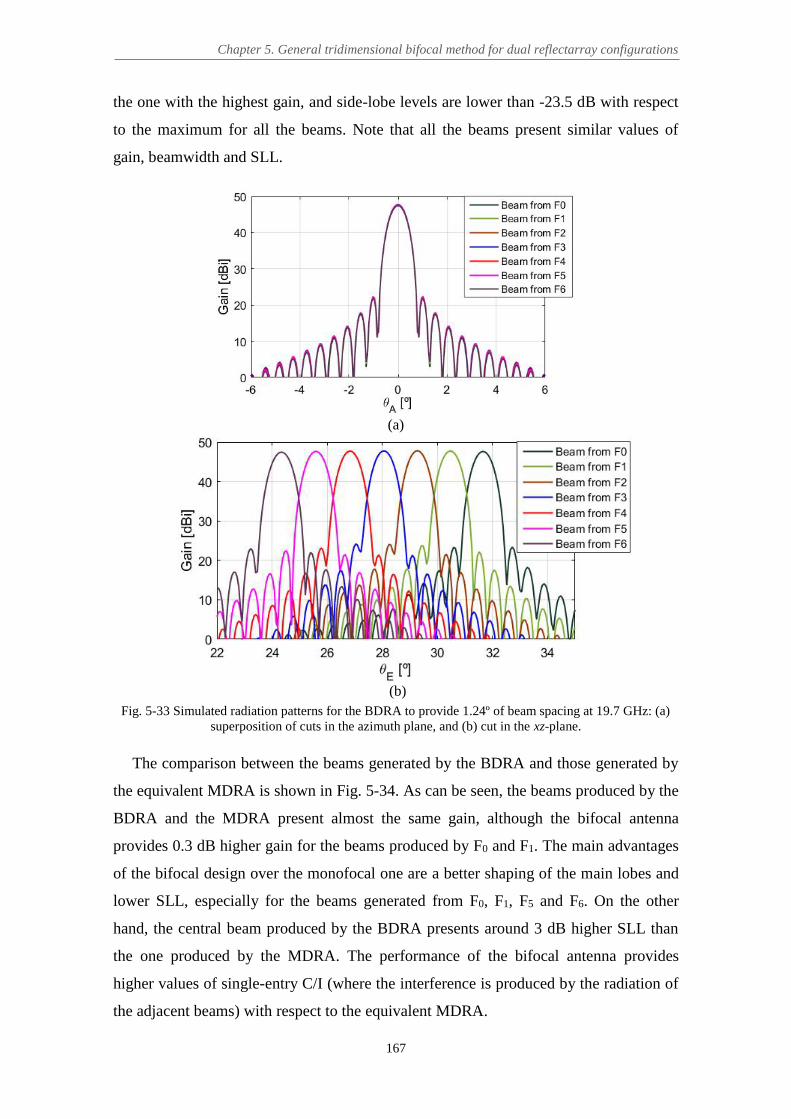
Chapter 5. General tridimensional bifocal method for dual reflectarray configurations
167
the one with the highest gain, and side-lobe levels are lower than -23.5 dB with respect
to the maximum for all the beams. Note that all the beams present similar values of
gain, beamwidth and SLL.
(a)
(b)
Fig. 5-33 Simulated radiation patterns for the BDRA to provide 1.24º of beam spacing at 19.7 GHz: (a) superposition of cuts in the azimuth plane, and (b) cut in the xz-plane.
The comparison between the beams generated by the BDRA and those generated by
the equivalent MDRA is shown in Fig. 5-34. As can be seen, the beams produced by the
BDRA and the MDRA present almost the same gain, although the bifocal antenna
provides 0.3 dB higher gain for the beams produced by F0 and F1. The main advantages
of the bifocal design over the monofocal one are a better shaping of the main lobes and
lower SLL, especially for the beams generated from F0, F1, F5 and F6. On the other
hand, the central beam produced by the BDRA presents around 3 dB higher SLL than
the one produced by the MDRA. The performance of the bifocal antenna provides
higher values of single-entry C/I (where the interference is produced by the radiation of
the adjacent beams) with respect to the equivalent MDRA.

Eduardo María Martínez de Rioja del Nido Ph.D. Thesis
168
Fig. 5-34 Comparison of the radiation patterns in the xz-plane for the beams generated at 19.7 GHz by the
BDRA (solid lines) and the equivalent MDRA (dashed lines).
The main characteristics of the bifocal beams, together with the improvement in the
single-entry C/I with respect to the MDRA, are summarized in Table 5-2. The single-
entry C/I has been measured within a 0.65º beamwidth, which corresponds to a gain of
around 44.75 dBi. Note that there are some small pointing errors in the central beams of
the bifocal design, but they are lower than the pointing errors in some of the extreme
beams of the equivalent MDRA (-0.04º error is obtained for the beam no. 4, -0.1º error
for the beam no. 5, and -0.15º error for the beam no. 6). The pointing errors in the
BDRA are in general smaller than the pointing errors of the satellite and can be
corrected in a second step by slightly adjusting the position of the feeds during the
detailed design of the antenna.
TABLE 5-2
MAIN CHARACTERISTICS OF THE BEAMS (BCR = 1)
No. beam Gain (dBi) Beamwidth at 44.7 dBi (º)
C/I (dB) ΔC/I (dB) Pointing error (º)
0 47.62 0.657 24.23 - 0 1 47.73 0.659 23.69 +4.63 +0.02 2 47.76 0.661 23.17 +2.71 +0.06 3 47.78 0.662 22.73 -0.53 +0.06 4 47.71 0.663 22.54 +1.86 +0.06 5 47.63 0.663 23.71 +4.32 +0.02 6 47.45 0.659 24.31 - 0
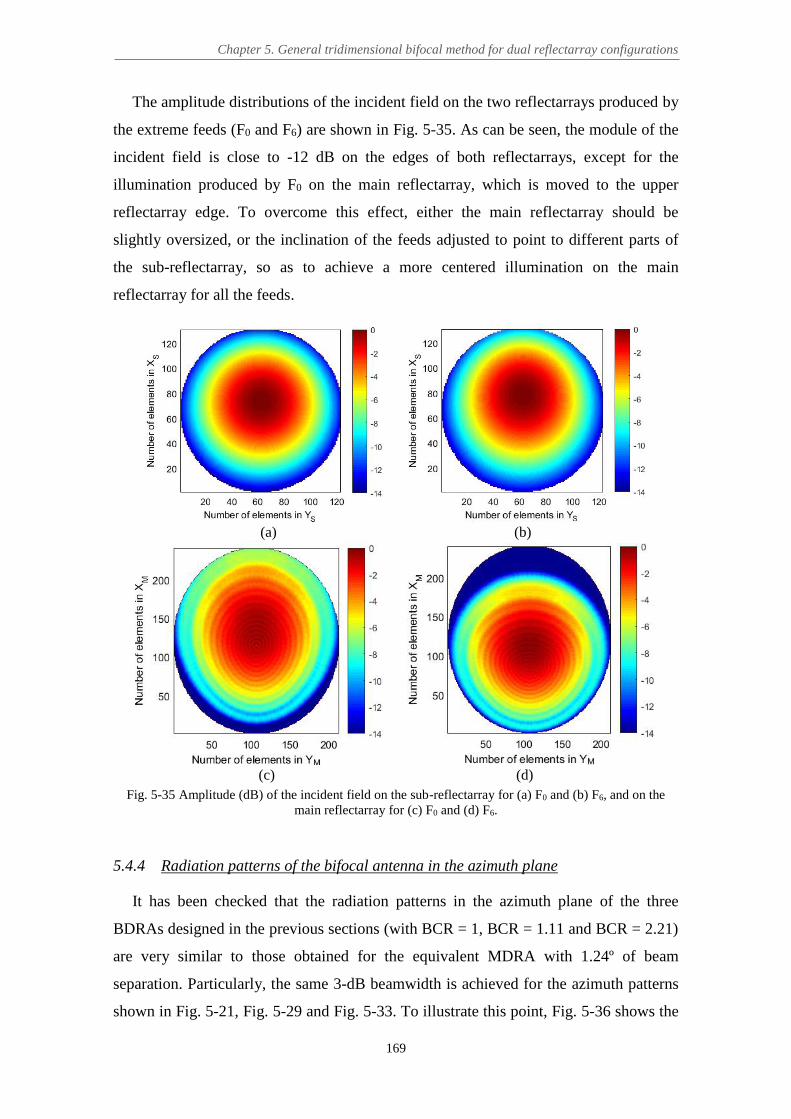
Chapter 5. General tridimensional bifocal method for dual reflectarray configurations
169
The amplitude distributions of the incident field on the two reflectarrays produced by
the extreme feeds (F0 and F6) are shown in Fig. 5-35. As can be seen, the module of the
incident field is close to -12 dB on the edges of both reflectarrays, except for the
illumination produced by F0 on the main reflectarray, which is moved to the upper
reflectarray edge. To overcome this effect, either the main reflectarray should be
slightly oversized, or the inclination of the feeds adjusted to point to different parts of
the sub-reflectarray, so as to achieve a more centered illumination on the main
reflectarray for all the feeds.
(a) (b)
(c) (d)
Fig. 5-35 Amplitude (dB) of the incident field on the sub-reflectarray for (a) F0 and (b) F6, and on the main reflectarray for (c) F0 and (d) F6.
5.4.4 Radiation patterns of the bifocal antenna in the azimuth plane
It has been checked that the radiation patterns in the azimuth plane of the three
BDRAs designed in the previous sections (with BCR = 1, BCR = 1.11 and BCR = 2.21)
are very similar to those obtained for the equivalent MDRA with 1.24º of beam
separation. Particularly, the same 3-dB beamwidth is achieved for the azimuth patterns
shown in Fig. 5-21, Fig. 5-29 and Fig. 5-33. To illustrate this point, Fig. 5-36 shows the

Eduardo María Martínez de Rioja del Nido Ph.D. Thesis
170
superposition of cuts in the azimuth plane at 19.7 GHz for the beam produced by F3
(central feed) in the MDRA and in the three designed BDRAs. As can be seen, quite
good agreement is achieved for the main lobe and the adjacent secondary lobes of the
patterns, except for the beam produced by the BDRA with BCR = 2.21, which presents
around 4 dB lower gain due to the high BCR. Furthermore, an additional beam has been
obtained in the azimuth plane, adjacent to the central beam, for the bifocal antennas
designed with BCR = 1.11 and BCR = 2.21, see Fig. 5-37. This beam is produced by a
54 mm feed-horn placed contiguous to F3 in the direction of y-axis, which is named F3*.
The spacing between the beams generated from F3 and F3* in both BDRAs is around
1.19º, which is almost the same beam spacing provided by the MDRA. However, the
main beam is slightly broadened for the BDRA with a high beam compression ratio.
Fig. 5-36 Comparison of the radiation patterns in the azimuth plane for the central beam generated in all
the previous DRA designs.
(a) (b)
Fig. 5-37 Simulated radiation patterns at 19.7 GHz in the azimuth plane: (a) for the BDRA with 1.12º of beam spacing in the xz-plane, and (b) for the BDRA with 0.56º of beam spacing in the xz-plane.

Chapter 5. General tridimensional bifocal method for dual reflectarray configurations
171
Therefore, it can be concluded that the BDRAs designed by using the 3D bifocal
technique are able to provide the required degree of beam spacing compression in the
xz-plane, while the monofocal characteristic of the equivalent MDRA is almost
preserved in the plane orthogonal to the xz. The reason for this behaviour is that the
phase distributions from the MDRA have been used to obtain the initial condition for
the phase derivatives along the sub-reflectarray cross section, when performing the 3D
bifocal design process. Changing the initial conditions for the bifocal algorithm (i. e.,
using a different monofocal design, or even a bifocal design, as reference to compute
the phase derivatives) will modify the performance of the BDRA in the azimuth plane.
5.4.5 Conclusions
The proposed 3D bifocal technique has been used for the design of a multi-beam
dual reflectarray antenna in an offset compact-range configuration. The antenna has
been designed at 19.7 GHz to operate in transmission (from the satellite) in Ka-band.
The 3D bifocal algorithm has been applied considering different degrees of beam
spacing compression with respect to the equivalent monofocal antenna: no beam
compression, low beam compression and high beam compression. It has been shown
that:
The use of the monofocal phases to obtain the initial conditions for the 3D
bifocal algorithm (the partial phase derivatives Ф’x and Ф’y along the sub-
reflectarray cross section) provides centered phase-shift distributions and a low
number of 360º cycles in the case of designing with BCR = 1 (no beam
compression).
The phase distributions obtained with the 3D bifocal method when BCR > 1 can
be corrected by adding a progressive phase term depending on x variable to the
monofocal phase distribution on the sub-reflectarray, without affecting the
radiation patterns of the bifocal antenna.
The bifocal antenna with BCR = 1 improves the performance of the extreme
beams with respect to the equivalent monofocal antenna when it is used for the
generation of multiple beams, providing a better shaping of the main lobe, lower
SLL and higher C/I.

Eduardo María Martínez de Rioja del Nido Ph.D. Thesis
172
The bifocal antenna with low beam compression (BCR = 1.11) allows to obtain
closer beams with non-overlapping feeds than in the equivalent monofocal
antenna, at the same time as improving the performance of the extreme beams.
The first factor allows to reduce the required antenna size with respect to
conventional antennas for the same beam spacing.
The bifocal antenna with high beam compression (BCR = 2.21) is able to
provide 0.56º of beam spacing, which is the required value for current multi-spot
satellite applications in Ka-band, although the radiation efficiency of the antenna
is reduced and the phases present a large number of 360º cycles. The main
reflectarray should be oversized to avoid the first problem.
The radiation patterns of the bifocal antenna in the azimuth plane are determined
by the performance of the equivalent monofocal antenna, whose phase
distributions have been used as initial condition for the 3D bifocal method. The
beam spacing provided by the BDRA in the azimuth plane will be the same than
the one provided by the MDRA.
5.5 Conclusions
A 3D bifocal design technique has been proposed for dual reflectarray antennas,
which makes it possible the direct synthesis of the required phase distributions in the
selected antenna configuration, without imposing any geometrical restrictions in the
positions of the focal points or the reflectarrays. The technique is based on an iterative
3D ray-tracing routine that alternates transmitted and received rays to provide a grid of
points that characterize each reflectarray (this iterative GO-based routine can be
considered as an extension of the 2D procedure shown in Chapter 3). The samples of
the partial phase derivatives Ф’x and Ф’y associated to the previous points are
interpolated by polynomials, and then, properly integrated to obtain the required bifocal
phase functions on each reflectarray. The initial condition for the partial phase
derivatives along the sub-reflectarray cross section can be determined, in the more
general case, from the equivalent single-focus design, considering the mid-point
between the foci of the bifocal antenna as the focus of the monofocal antenna.
The 3D bifocal technique has been validated for the axially-symmetrical dual
reflectarray configuration presented in Chapter 3 (section 3.2). The results obtained by

Chapter 5. General tridimensional bifocal method for dual reflectarray configurations
173
the 3D bifocal technique have been compared with those achieved by applying the 2D
bifocal algorithm in the offset plane followed by the rotation of the resulting phase
curves around the antenna symmetry axis. The results of this comparison are very
satisfactory, as the differences between the two design methods are practically
negligible.
A multi-beam dual reflectarray antenna has been designed to operate in transmission
in Ka-band (19.7 GHz) with a 1.8 x 1.6 m main reflectarray and a 1.3 x 1.2 m sub-
reflectarray. The antenna presents a dual offset compact-range configuration, which
precludes the application of the bifocal method shown in Chapter 3. The required phase-
shift distributions on both reflectarrays have been obtained by means of the proposed
3D bifocal technique, considering three different degrees of beam spacing compression:
no compression (1.24º of beam spacing), low compression (from 1.24º to 1.12º) and
high compression (from 1.24º to 0.56º). The results have been compared with those
provided by the equivalent single-focus antenna with the same configuration. The
bifocal antenna with no beam compression improves the performance of the extreme
beams with respect to the equivalent monofocal antenna in terms of beam shaping, SLL
and C/I. The bifocal antenna with low beam compression allows to obtain closer beams
with non-overlapping feeds than in the equivalent monofocal antenna, at the same time
than improving the performance of the extreme beams. Finally, the bifocal antenna with
high beam compression is able to provide the required 0.56º spacing for the current
multi-spot applications in Ka-band, although the radiation efficiency of the antenna is
reduced.
Among the three cases studied, the bifocal antenna with low beam spacing
compression is probably the most promising for multi-beam antennas in Ka-band, as it
combines the smaller beam spacing with an improvement of the antenna performance
for the generation of multiple beams. The first factor will allow to reduce the antenna
size with respect to conventional reflectors to provide the same beam spacing.
Moreover, the manufacturing of the bifocal dual reflectarray antenna will involve the
same conventional processes used for printed reflectarrays (unlike the case of bifocal
dual reflectors, which require expensive custom moulds for the two shaped reflectors).
For these reasons, the bifocal antenna with low beam compression has been the selected
option for the design, manufacturing and testing of a DRA prototype that will be used to
validate the proposed bifocal technique, as will be shown in the following chapter.

174

175
Chapter 6
Design, manufacturing and test of a bifocal dual reflectarray antenna
demonstrator
6.1 Introduction
A bifocal dual reflectarray antenna (BDRA) demonstrator that operates in dual-linear
polarization in the 19.2-20.2 GHz band (transmission frequencies from a satellite in Ka-
band) has been designed, manufactured and tested, in order to validate the bifocal
technique and show its main advantages with respect to the equivalent single-focus
design: a better antenna performance for the generation of multiple beams and a closer
separation between adjacent beams for the same feed spacing.
The antenna configuration is based on an offset compact-range geometry, which is a
small-scale version of the one used in Chapter 5 for the design of a multi-beam transmit
antenna in Ka-band. The absence of axial symmetry and the large tilting angle of the
sub-reflectarray with respect to the main reflectarray preclude the application of the
bifocal design procedure proposed in Chapter 3. Therefore, the synthesis of the required
phase-shift distributions on each reflectarray will be carried out by means of the 3D
bifocal method presented in Chapter 5.
The BDRA demonstrator generates 10 beams alternating in dual-linear polarization
when the antenna is illuminated by 5 contiguous feed-horns, but the method can be
extended to generate adjacent beams in dual-circular polarization by implementing a
sequential rotation of the reflectarray elements [59]. The spacing between adjacent
beams in the same polarization is 3.8º, which means that the beams are compressed by a
factor of 1.2 with respect to the equivalent monofocal design (4.6º of spacing).
Moreover, the fabrication of the BDRA prototype involves the same conventional

Eduardo María Martínez de Rioja del Nido Ph.D. Thesis
176
processes used for printed reflectarrays, thus avoiding the high manufacturing costs of
shaped bifocal dual reflectors. Finally, the same concept can be used for the design of
transmit and receive antennas if appropriate reflectarray cells that enable independent
phasing at Tx and Rx frequencies are employed [60], [68], [129], [130].
6.2 Design of the bifocal dual reflectarray antenna demonstrator
A BDRA demonstrator has been designed, manufactured and tested in order to
validate the proposed bifocal technique and show its ability to reduce beam spacing,
while providing a better performance for the extreme beams than the equivalent
monofocal dual reflectarray antenna (MDRA). The prototype has been designed at 19.7
GHz to operate in the 19.2-20.2 GHz band, which are transmission frequencies from the
satellite in Ka-band. A separate design process has been performed for each linear
polarization, in order to obtain the required bifocal phase-shift distributions that must be
implemented on each reflectarray.
6.2.1 Antenna definition
Figure 6-1 shows the geometry of the BDRA demonstrator, whose main parameters
are summarized in Table 6-1. An arrangement of 5 contiguous feeds (from F1 to F5)
placed in the xz-plane has been considered to illuminate the antenna. The diameter of
the feed-horns is 60 mm, so the separation between the phase centers of adjacent feeds
has been set to 61 mm, in order to allow a 1 mm margin to properly accommodate the
horns. The antenna geometry has been adjusted to avoid blockage from the feeds or the
sub-reflectarray.
Fig. 6-1 Geometry of the DRA demonstrator.

Chapter 6. Design, manufacturing and test of a bifocal dual reflectarray antenna demonstrator
177
As previously explained, an offset compact-range configuration has been selected for
the BDRA demonstrator. This configuration is characterized by its large F/D ratio (see
Fig. 6-2), associated to the virtual focus of the equivalent parabolic main reflector. The
large focal distance will allow for smoother phase distributions (with a low number of
360º cycles) on the main reflectarray, as will be shown later. Moreover, the antenna
requires less space than a Cassegrain or Gregorian configuration, thanks to the compact
arrangement of the two reflectarrays and the feeds. The size of the sub-reflectarray has
been selected for a subtended angle of around 30º from the feeds, which will provide
around -12 dB edge illumination on its edges. Also, both reflectarrays are slightly
elliptical, in order to ensure proper illuminations.
Fig. 6-2 Compact-range dual reflectarray configuration with large F/D.
TABLE 6-1 MAIN GEOMETRICAL PARAMETERS OF THE BDRA DEMONSTRATOR
Parameter Value
Size Main-RA 570 x 420 mm (76 x 56 elements)
Size Sub-RA 390 x 352.5 mm (52 x 47 elements)
Angle of tilting Sub-RA 51.1º
Center Main-RA [0, 0, 0] mm
Center Sub-RA [-240.3, 0, 330.7] mm
Phase center F1 (focus 1 BDRA) [337.1, 0, 47.8] mm
Phase center F5 (focus 2 BDRA) [403.2, 0, 282.8] mm
Distance F1-F5 244 mm
Phase center F3 (focus MDRA) [370.1, 0, 165.3] mm
Virtual focus related to F3 [-1321.4, 0, 2384.5] mm

Eduardo María Martínez de Rioja del Nido Ph.D. Thesis
178
6.2.2 Characterization of the feed
A 60-mm diameter horn manufactured by ANTERAL [131] has been used to
illuminate the dual reflectarray demonstrator (see Fig. 6-3). The horn meets all the
requirements for current multi-spot satellite applications in Ka-band, so it operates both
at Tx and Rx frequency bands (17.6-20.3 GHz for Tx band and 27.3-30.1 GHz for Rx
band), providing very low levels of cross-polar radiation and a high aperture efficiency.
The inner profile of the horn is shown in Fig. 6-4, together with the position of its phase
center at each frequency band. For design purposes, the position of the phase center at
19.7 GHz has been estimated at 5 mm inside the aperture plane.
Fig. 6-3 Feed-horn antenna.
Fig. 6-4 Inner profile of the horn and position of its phase center at each frequency band [131].
A simplistic model based on a cosq(θ) distribution has been then used to simulate the
electromagnetic field radiated by the horn. Note that the sub-reflectarray elements are
placed in the far field region of the feeds, since 2·D2/λ = 473 mm and the distances from
the horn locations (F1 to F5) to the sub-reflectarray elements are comprised between 560
mm and 775 mm. The radiation patterns of the horn provided by the manufacturer at

Chapter 6. Design, manufacturing and test of a bifocal dual reflectarray antenna demonstrator
179
18.9 and 20.3 GHz are shown in Fig. 6-5. The horn presents a directivity of 20.9 dBi at
18.9 GHz, while 21.6 dBi directivity is achieved at 20.3 GHz. The aperture efficiency is
close to 0.89 and cross-polar levels are lower than -25 dB respect to the co-polar
maximum within a 12-dB beamwidth. The radiation patterns present a different
beamwidth in the two principal planes when operating in linear polarization, as can be
seen in Fig. 6-5, where the dashed lines indicate the half-subtended angle to get an edge
illumination level of -12 dB on the sub-reflectarray. The 12-dB beamwidth of the horn
at 19.7 GHz has been estimated at 29º in the E-plane and at 32.2º in the H-plane.
(a) (b)
Fig. 6-5 Radiation patterns of the feed at: (a) 18.9 GHz and (b) 20.3 GHz [131].
According to the previous data, the electromagnetic field radiated by the horn at 19.7
GHz has been modelled by a cosq(θ) function with q = 43 in the xz-plane (which
corresponds to a 12-dB beamwidth of 29º in the E-plane of the horn) and q = 35 in the
azimuth plane (12-dB beamwidth of 32.2º in the H-plane of the horn) for X-
polarization, while the q values are reversed for Y-polarization, since the field of the
horn is rotated 90 degrees.
6.2.3 Design of the reflectarray unit cell
A single-layer unit cell based on orthogonal arrangements of parallel dipoles has
been used for the design of both sub- and main reflectarrays (see Fig. 6-6). There are
three parallel dipoles for controlling the phases that will be introduced in each linear

Eduardo María Martínez de Rioja del Nido Ph.D. Thesis
180
polarization at 19.7 GHz. The side dipoles of each set present the same dimensions, so
as to keep low levels of cross-polar radiation [30]. The period is fixed at PX = PY = 7.5
mm, which is λ/2 at 20 GHz. This allows to avoid the appearance of grating lobes and
provide enough range of phase-shift at 19.7 GHz, while preventing orthogonal dipoles
from overlapping.
Fig. 6-6 View of the reflectarray periodic structure, including four unit-cells for X-polarization and one unit-cell for Y-polarization.
The geometrical parameters of the cell have been adjusted to provide a linear
response of the phase with respect to the dipoles’ lengths and robustness against
variations in the angle of incidence. In this sense, a width of 0.5 mm has been selected
for all dipoles, the center-to-center separations are SA = SB = 1 mm, and a scale factor of
0.78 is considered for the lengths of side dipoles with respect to the length of the central
ones (lA1 = 0.78·lA2 and lB1 = 0.78·lB2). The substrate layer has been implemented by a
Diclad 880B sheet with a thickness (h) of 1.524 mm and a loss tangent (tanδ) of 0.001.
For design purposes, the measured value of the dielectric constant at 20 GHz (εr = 2.3)
has been used, instead of the nominal value (εr = 2.17 at 10 GHz) provided by the
manufacturer.
The analysis and design of the reflectarray element has been carried out by means of
a home-made SD-MoM (Method of Moments in the Spectral Domain) code, which uses
entire domain basis functions to approximate the current densities on the dipoles, and
assumes an infinite periodic array model for the analysis of each cell [101]. The SD-
MoM code takes into account the real angles of incidence on each reflectarray cell to
compute the co- and cross-polar coefficients that form the reflection matrix of the cell
(further details can be found in Chapter 2). Figure 6-7 shows the magnitude and phase
of the co-polar reflection coefficient for X and Y polarizations under different angles of

Chapter 6. Design, manufacturing and test of a bifocal dual reflectarray antenna demonstrator
181
incidence, which are the highest angles from the feeds on the sub-reflectarray cells and
from the virtual focus on the main reflectarray cells. As can be seen, the phase curves
are quite linear in a range larger than 360º, and variations with the angle of incidence
are lower than 25º in the worst case.
(a)
(b)
Fig. 6-7 Magnitude and phase of the co-polar reflection coefficient at 19.7 GHz, considering the most critical angles of incidence: (a) for X-polarization and (b) for Y-polarization.

Eduardo María Martínez de Rioja del Nido Ph.D. Thesis
182
6.2.4 Design of the dual reflectarray antenna
Considering the geometry of the DRA demonstrator shown in Fig. 6-1, a single-focus
reference design has been performed at 19.7 GHz for the central feed (F3) to produce
two beams in the directions (θ3X = 27.8º, φ3X = 0º) for X-polarization and (θ3Y = 29.7º,
φ3Y = 0º) for Y-polarization. The required phase-shift distributions on each reflectarray
associated to this monofocal antenna are shown in Fig. 6-8 for both polarizations. The
calculation of these phases has been performed following the same procedure than in
[71], as in the case of the MDRA design presented in Chapter 5.
(a) (b)
(c) (d)
Fig. 6-8 Monofocal phase distributions (in degrees) at 19.7 GHz on the sub-reflectarray (a) in X-pol. and (b) in Y-pol.; and on the main reflectarray (c) in X-pol. and (d) in Y-pol.
The bifocal phase distributions that must be implemented on each reflectarray have
been calculated by performing two independent bifocal design processes, one for each
polarization. For this purpose, the phase centers of the feeds F1 and F5 have been
selected as the foci of the bifocal antenna. The directions of the beams generated by the
foci in each linear polarization are: (θ1X = 35.4º, φ1X = 0º) and (θ1Y = 37.3º, φ1Y = 0º) for
feed F1; and (θ5X = 20.2º, φ5X = 0º) and (θ5Y = 22.1º, φ5Y = 0º) for feed F5. Note that the
beams in Y-polarization are shifted 1.9º with respect to those in X-polarization. The

Chapter 6. Design, manufacturing and test of a bifocal dual reflectarray antenna demonstrator
183
spacing between beams in the same polarization produced by contiguous feeds is 3.8º,
while it is 4.6º in the equivalent MDRA (as will be shown later, see Fig. 6-10). So, the
BDRA demonstrator reduces the beam spacing provided by the MDRA by a factor of
4.6º/3.8º = 1.2, for the same feed spacing. The resulting bifocal phase distributions to be
implemented at 19.7 GHz in X and Y polarizations are shown in Fig. 6-9.
(a) (b)
(c) (d)
Fig. 6-9 Bifocal phase distributions (in degrees) to be implemented at 19.7 GHz on the sub-reflectarray (a) in X-pol. and (b) in Y-pol., and on the main reflectarray (c) in X-pol. and (d) in Y-pol.
The lengths of the dipoles are obtained in each reflectarray cell by iteratively calling
an analysis routine that adjusts the lengths and analyzes the cell by a SD-MoM method
assuming local periodicity to match the required phase-shift at each cell obtained by the
bifocal technique, see Fig. 6-9. The variable lA2 is used to control X-polarization, while
the variable lB2 controls Y-polarization. These variables can be separately adjusted
thanks to the uncoupling of the phase response between orthogonal sets of dipoles [30].
In the design of the sub-reflectarray cells, the incidence angles from the central feed (F3)
have been taken into account, in order to minimize variations in the phase of the
reflection coefficient when illuminating with a different feed. Similarly, the incidence
angles from the virtual focus of the DRA system related to F3 have been considered in
the design of the main reflectarray cells.

Eduardo María Martínez de Rioja del Nido Ph.D. Thesis
184
6.2.5 Comparison with the equivalent single-focus antenna
Prior to the manufacturing of the demonstrator, some simulations have been
performed by assuming ideal reflectarray cells in order to compare the beams from the
BDRA demonstrator with those from the equivalent MDRA. The two DRA systems
have been analyzed by applying the modular technique described in [70], which has
been previously validated in the design of other dual reflectarray demonstrators [71]. A
cosq(θ) function with q = 43 has been used to model the field radiated by the 60 mm
feed-horns, which provides around -12 dB illumination on the edges of the sub-
reflectarray. The comparison of the simulated radiation patterns in the xz-plane for the
designed BDRA and the equivalent MDRA is shown in Fig. 6-10(a) for the beams in X-
polarization, and in Fig. 6-10 (b) for the beams in Y-polarization.
(a)
(b)
Fig. 6-10 Simulated radiation patterns at 19.7 GHz in the xz-plane for the beams generated by the BDRA (solid lines) and by the equivalent MDRA (dashed lines): (a) in X-polarization, (b) in Y-polarization.

Chapter 6. Design, manufacturing and test of a bifocal dual reflectarray antenna demonstrator
185
As can be seen, the bifocal beams present similar values of gain (a difference of 1.2
dB between the central beam and the beam produced by F5, which presents the lowest
gain), beamwidth (around 2.6º at -3 dB) and SLL (around -23 dB with respect to the
maximum). On the other hand, the MDRA provides a better performance for the central
beam (-31 dB of SLL), but the extreme beams are quite broadened and the gain
variation with respect to the central beam is around 1.5 dB. Moreover, the MDRA
presents around 4.6º of separation between adjacent beams in the same polarization,
while the BDRA is able to reduce this value to 3.8º for the same feed spacing. The ratio
of beam spacing compression provided by the BDRA is 4.6º/3.8º = 1.2.
Figure 6-11 shows the superposition of the radiation patterns in the xz-plane for the
10 beams generated by the BDRA in both X and Y polarizations, where the separation
between adjacent beams in orthogonal polarizations is 1.9º.
Fig. 6-11 Simulated radiation patterns in the xz-plane for the beams in X and Y polarizations generated by
the BDRA (ideal phases).
Figure 6-12 shows the amplitude distributions of the incident field on each
reflectarray, considering illumination from the foci of the BDRA (F1 and F5), and from
the central feed (F3). As can be seen, the edge illumination levels on the sub-reflectarray
are close to -12 dB for the three cases. The feed placed at F1 produces a higher
illumination on the upper part of the main reflectarray, while the feed placed at F5
illuminates more its bottom part. In the latter case, the illumination levels reach -8 dB
on the lower edge of the main reflectarray (the main reflectarray should be slightly
oversized to reduce spillover).

Eduardo María Martínez de Rioja del Nido Ph.D. Thesis
186
(a) (b)
(c) (d)
(e) (f)
Fig. 6-12 Amplitude (dB) of the incident field: (a) on the sub-reflectarray produced by F1, (b) on the main reflectarray produced by F1, (c) on the sub-reflectarray produced by F3, (d) on the main reflectarray
produced by F3, (e) on the sub-reflectarray produced by F5, (f) on the main reflectarray produced by F5.
Finally, Fig. 6-13 shows the superposition of the radiation patterns in the azimuth
plane (the one orthogonal to the xz-plane in the direction of the beam) for the BDRA
and the equivalent MDRA, corresponding to the beam produced by F3 in X-polarization
at 19.7 GHz. The patterns show a very good agreement, since the phases of the MDRA

Chapter 6. Design, manufacturing and test of a bifocal dual reflectarray antenna demonstrator
187
have been used to obtain the values of the partial phase derivatives at the starting points
of the bifocal algorithm. Therefore, the radiation patterns of the BDRA in the azimuth
plane maintain the same characteristics than those of the MDRA.
Fig. 6-13 Simulated radiation patterns in the xz-plane for the beams in X and Y polarizations generated by the BDRA (ideal phases).
6.3 Manufacturing of the dual reflectarray demonstrator
The designed BDRA demonstrator has been manufactured and tested. Both sub- and
main reflectarrays are made on a single layer of DiClad 880B. The dipoles are printed
on the upper side of the substrate by conventional photo-etching process. Figure 6-14
shows the lateral view of the sandwich configuration for both reflectarrays.
Fig. 6-14 Sandwich configuration of both reflectarrays.
The dimensions of the reflectarray panels have been slightly increased, in order to
allow an outer frame without dipoles that makes it possible to fix the antennas on the
supporting plates with nylon screws. The dimensions of the main reflectarray panel are
570 x 510 mm (the main reflectarray size is 570 x 420 mm, as indicated in Table 6-1),
while the sub-reflectarray panel has 405 x 427.5 mm (the sub-reflectarray size is 390 x
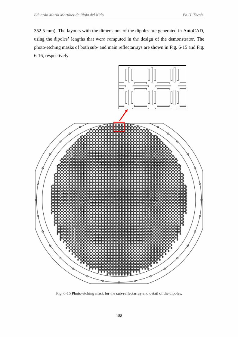
Eduardo María Martínez de Rioja del Nido Ph.D. Thesis
188
352.5 mm). The layouts with the dimensions of the dipoles are generated in AutoCAD,
using the dipoles’ lengths that were computed in the design of the demonstrator. The
photo-etching masks of both sub- and main reflectarrays are shown in Fig. 6-15 and Fig.
6-16, respectively.
Fig. 6-15 Photo-etching mask for the sub-reflectarray and detail of the dipoles.

Chapter 6. Design, manufacturing and test of a bifocal dual reflectarray antenna demonstrator
189
Fig. 6-16 Photo-etching mask for the main reflectarray.
The two reflectarrays have been manufactured and assembled on an aluminum
structure, which also supports the 60-mm feed-horn from ANTERAL. Three different
feed supports have been manufactured, in order to place the horn at positions F1, F3 and
F5 given in Table 6-1 (the two foci of the bifocal antenna and the central feed). An
AutoCAD scheme with the structure of the dual reflectarray demonstrator is shown in
Fig. 6-17, with the feed placed at position F1. The resulting breadboard at the facilities
of the Applied Electromagnetics Group of Universidad Politécnica de Madrid can be
seen in Fig. 6-18.

Eduardo María Martínez de Rioja del Nido Ph.D. Thesis
190
Fig. 6-17 AutoCAD scheme with the structure of the BDRA demonstrator with the feed-horn placed at position F1.
Fig. 6-18 Manufactured BDRA demonstrator with the feed-horn placed at position F5.

Chapter 6. Design, manufacturing and test of a bifocal dual reflectarray antenna demonstrator
191
6.4 Measurement of the dual reflectarray demonstrator and
comparison with simulations
The BDRA prototype has been measured at the facilities of Universidad Politécnica
de Madrid (UPM), in a compact-range measurement system. Figure 6-19 shows three
pictures of the breadboard in the anechoic chamber of UPM with the horn placed at
positions F1, F3 and F5.
(a)
(b)
(c)
Fig. 6-19 Pictures of the BDRA demonstrator in the compact-range anechoic chamber with the feed-horn placed at: (a) position F1, (b) position F3 and (c) position F5.

Eduardo María Martínez de Rioja del Nido Ph.D. Thesis
192
The comparison of the simulated and experimental radiation patterns at 19.7 GHz in
the xz-plane for the beams produced in X and Y polarizations is presented in Fig. 6-20,
considering illumination from F1, F3 and F5. Then, Fig. 6-21 shows the comparison of
the radiation patterns at 19.7 GHz in the azimuth plane for the beams produced in both
polarizations when the feed is placed at F1 (similar results are obtained for the beams
generated from F3 and F5). The patterns include the co- and cross-polar components for
each linear polarization. The simulations take into account the final design of the dual
reflectarray antenna with the (3+3) dipole element, i. e., the tangential reflected field on
each reflectarray cell has been computed by means of the aforementioned SD-MoM
code. The effect of the outer frame without dipoles in both reflectarray panels has been
also considered in the simulations. According to what was exposed in section 6.2.2, the
field radiated by the horn has been modelled by a cosq(θ) function with q = 43 in the E-
plane (12-dB beamwidth of 29º), which means in xz-plane for X-polarization and in
azimuth plane for Y-polarization, and q = 35 in the H-plane (12-dB beamwidth of
32.2º), which means in xz-plane for Y-polarization and in azimuth plane for X-
polarization. As can be seen in Fig. 6-20, a quite good agreement is achieved between
simulations and measurements in the xz-plane, where the bifocal antenna is able to
produce the beams in the required directions in both polarizations. In the case of the
azimuth patterns (see Fig. 6-21), the main difference between measurements and
simulations is the filling of the first nulls adjacent to the main lobe. An overview of the
antenna performance at 19.7 GHz is shown in Table 6-2, which compares the simulated
and experimental values of gain, SLL and XPD (measured within a 3-dB beamwidth)
for the six beams generated from F1, F3 and F5.
TABLE 6-2
COMPARISON OF MAIN ANTENNA PARAMETERS AT 19.7 GHZ
Feed Gain
simul. (dB)
Gain meas. (dB)
SLL simul. (dB)
SLL meas. (dB)
XPD simul. (dB)
XPD meas. (dB)
Pol. X
1 36.28 36.11 21.02 20.46 37.93 31.18 3 36.41 36.26 19.75 19.43 31.81 29.87
5 35.18 34.85 19.49 17.85 35.78 33.21
Pol. Y
1 36.29 36.15 19.18 17.28 32.87 27.84 3 36.52 36.31 19.23 17.62 30.85 26.12
5 35.27 35.13 16.74 16.63 28.57 23.94

Chapter 6. Design, manufacturing and test of a bifocal dual reflectarray antenna demonstrator
193
(a)
(b)
(c)
Fig. 6-20 Measured and simulated radiation patterns at 19.7 GHz in the xz-plane considering illumination from: (a) F1, (b) F3 and (b) F5.

Eduardo María Martínez de Rioja del Nido Ph.D. Thesis
194
(a)
(b)
Fig. 6-21 Measured and simulated radiation patterns at 19.7 GHz in the azimuth plane for the beams produced by the feed at F1: (a) in X-polarization and (b) in Y-polarization.
The discrepancies between the measured and simulated radiation patterns of the
bifocal antenna in the azimuth plane (filling of the first nulls adjacent to the main lobe)
are mainly caused by the simplistic modelling of the horn, which has been simulated by
a cosq(θ) distribution that considers the same position for the horn phase center in the
two orthogonal planes. A shifting of the phase center in the azimuth plane (not taken
into account in the simulations) would produce such effects on the antenna radiation
patterns, which could be also worsened by phase errors due to tolerances in the dipole
dimensions and in the dielectric constant of the substrate. A full-wave simulation of the
feed-horn should be used to compute accurately the incident field on the sub-
reflectarray for each feed.

Chapter 6. Design, manufacturing and test of a bifocal dual reflectarray antenna demonstrator
195
(a)
(b)
(c)
Fig. 6-22 Measured radiation patterns in the xz-plane at the central and extreme frequencies of the 19.2-20.2 GHz band considering illumination from: (a) F1, (b) F3 and (b) F5.

Eduardo María Martínez de Rioja del Nido Ph.D. Thesis
196
After validating the bifocal technique by comparison of the measured and simulated
radiation patterns at 19.7 GHz (design frequency), the radiation patterns of the bifocal
antenna in the xz-plane have been measured at the extreme frequencies of the 19.2-20.2
GHz band, in the cases where illumination from F1, F3 and F5 is considered. The results
are shown in Fig. 6-22. It has been checked that some of these patterns present small
deviations in the beam directions lower than ±0.1º. Also, there is a gain variation lower
than 1.2 dB, and around 2-3 dB higher SLL with respect to the patterns at the central
frequency of the band.
The gain of the bifocal antenna has been measured within the prescribed band for the
six beams generated from F1, F3 and F5, and the resuls are presented in Fig. 6-23. The
maximum gain variation is equal to or lower than 1.2 dB for all the beams, showing a
steady response within the band. It can be noticed that the two beams produced from F5
present around -1 dB lower gain than the beams from F1 and F3, although this was
expected after checking the results of the simulations with ideal phases (see Fig. 6-10).
The reduction in gain for the beams associated to F5 is produced because the
illumination on the main reflectarray is moved to the reflectarray edge. To overcome
this effect, the main reflectaray should be slightly oversized. The radiation efficiency of
the bifocal antenna, calculated as the ratio between the measured gain and the maximum
directivity, varies from 66% to 70% within the prescribed frequency band.
Fig. 6-23 Measured gain versus frequency for the six beams generated by F1, F3 and F5 in X and Y polarizations.
The breadboard has been also tested in a spherical near-field measurement system at
UPM to compute 3D radiation patterns, in the case where the horn is placed at position

Chapter 6. Design, manufacturing and test of a bifocal dual reflectarray antenna demonstrator
197
F1 (see Fig. 6-24). The radiated field has been measured for both X and Y polarizations
in the angular range -80° < θ < 80°, -180° < φ < 180°. The simulated and measured
radiation patterns in (u, v) coordinates at 19.7 GHz for the co-polar components of both
polarizations generated from F1 are in good agreement and can be seen in Fig. 6-25.
Fig. 6-24 Picture of the BDRA demonstrator in the spherical near-field measurement system.
(a) (b)
(c) (d)
Fig. 6-25 Radiation patterns (in dB) for the co-polar component produced by F1 at 19.7 GHz: for X-polarization (a) simulated and (b) measured, and for Y-polarization (c) simulated and (d) measured.

Eduardo María Martínez de Rioja del Nido Ph.D. Thesis
198
The comparison of the simulated and measured radiation patterns in (u, v)
coordinates at 19.7 GHz for the cross-polar components of both polarizations generated
from F1 is presented in Fig. 6-26. The patterns show very low levels of cross-
polarization in all directions (no conversion from co-polar to cross-polar radiatied
fields), which makes it difficult to reach a very good accordance with the simulations.
(a) (b)
(c) (d)
Fig. 6-26 Radiation patterns (in dB) for the cross-polar component produced by F1 at 19.7 GHz: for X-polarization (a) simulated and (b) measured, and for Y-polarization (c) simulated and (d) measured.
The superposition of the simulated and measured radiation pattern contours at -3 dB
(respect to the maximum gain) for the two beams produced by F1 at 19.7 GHz is
presented in Fig. 6-27, and the measured -3 dB contours of the same beams at the
central and extreme frequencies of the prescribed frequency band (19.2-20.2 GHz) are
shown in Fig. 6-28. As can be seen, there is only a slight beam squint (+0.09º) at the
higher frequency. These results show that the bifocal antenna is able to produce two
adjacent beams in dual-linear polarization for each feed. The beams can also be
generated in dual-circular polarization if the orthogonal CP are discriminated by means
of the variable rotation technique, as proposed in [59]. This concept can be used for the

Chapter 6. Design, manufacturing and test of a bifocal dual reflectarray antenna demonstrator
199
design of a multi-beam antenna in Ka-band to provide adjacent beams in orthogonal
polarizations with a smaller spacing than the equivalent single-focus antenna
Fig. 6-27 Comparison of the simulated and measured -3 dB pattern contours at 19.7 GHz for the beams
produced from F1 in X and Y polarizations.
Fig. 6-28 Measured -3 dB contours at the central and extreme frequencies of the prescribed band for the
beams produced from F1 in X and Y polarizations.
6.5 Conclusions
A bifocal dual-reflectarray antenna demonstrator with a main reflectarray of
dimensions 57 x 42 cm has been designed, manufactured and tested for the first time.
The prototype has been designed at 19.7 GHz to operate in the 19.2-20.2 GHz band
(transmission frequencies from the satellite in Ka-band). Due to the large offset of the
antenna geometry, the calculation of the required phase-shift distributions on each
reflectarray has been performed by means of the 3D bifocal method presented in
Chapter 5. Two separate bifocal design processes have been carried out, one for each
Eduardo María Martínez de Rioja del Nido Ph.D. Thesis
200
linear polarization. A single-layer reflectarray element, consisting of two orthogonal
sets of three parallel dipoles, has been used to implement the required phase-shifts on
both sub- and main reflectarrays by properly adjusting the lengths of the parallel
dipoles. The BDRA is designed to provide 10 beams alternating in dual-linear
polarization when the antenna is illuminated by 5 feed-horns, but the technique can be
used to generate adjacent beams in dual-circular polarization by using a sequential
rotation method.
The measured patterns show both a good agreement with the simulations and a
steady response within the prescribed frequency band (19.2-20.2 GHz), with a
maximum gain variation of 1.2 dB. The bifocal antenna provides the required beam
directions, with 3.8º of separation between beams generated by contiguous feeds in the
same polarization (1.9º between adjacent beams in orthogonal polarizations). The side-
lobe levels are lower than -17 dB below the co-polar maximum, while the cross-polar
discrimination varies from 24 to 34 dB. There are slight discrepancies between the
measured and simulated radiation patterns in the azimuth plane, which are a
consequence of the use of a simplistic electromagnetic model for the horn. However,
these discrepancies do not have any effect on the antenna performance in the xz-plane
(the plane that contains the radiated beams), which is determined by the bifocal
technique. The BDRA demonstrator has validated the capabilities of the bifocal
technique to improve the multi-beam performance in two directions:
1) Reduction of the beam spacing in a certain degree (in this case, by a factor of 1.2)
with respect to the equivalent monofocal antenna, with a similar radiation
efficiency (close to 70%) and using non-overlapping feeds. The smaller beam
spacing will make it possible a reduction in the required antenna size with respect
to conventional reflectors for the same beam spacing.
2) Improvement of the beams far away of the focal position, which present better
results for the gain (+0.3 dB), SLL (-2 dB) and 3-dB beamwidth (2.6º, similar to
the other beams) than in the equivalent monofocal antenna. A further
optimization could be carried out in order to fulfill additional SLL or XPD
requirements for current multi-beam satellite antennas in Ka-band, although this
optimization should not disturb the phase distributions obtained by the bifocal
technique.

Chapter 6. Design, manufacturing and test of a bifocal dual reflectarray antenna demonstrator
201
Furthermore, the manufacturing of the BDRA involves the same conventional photo-
etching processes used for printed reflectarrays, as the only difference with respect to
the equivalent MDRA are the dimensions of the printed elements. This will make it
possible to improve the multi-beam performance of current satellite antennas in Ka-
band (when designed for a single focus) without increasing the costs of the antenna
system. In the case of bifocal dual reflectors, both reflectors are shaped as a
consequence of the bifocal design process, thus requiring expensive metallic moulds
that should be manufactured specifically for each mission. But this problem is avoided
using the proposed bifocal dual-reflectarray antenna.
Finally, the proposed concept can be extended to the design of transmit and receive
antennas in Ka-band by the use of dual-frequency reflectarray cells that enable
independent phasing at Tx (20 GHz) and Rx (30 GHz) frequencies (as those presented
in Chapter 2). In this case, independent bifocal processes will be carried out for each
frequency band, in order to obtain the required phase distributions to be implemented by
the reflectarray elements.

202

203
Chapter 7
Bifocal antenna with elliptical main reflectarray for multi-spot coverage
in Ka-band
7.1 Introduction
This chapter describes the design of a multi-beam dual reflectarray antenna to
provide multi-spot coverage for transmission from a geostationary satellite operating in
Ka-band (20 GHz). The beam spacing in the offset plane is reduced by a factor of 1.8
with respect to the equivalent monofocal antenna, thanks to the use of the bifocal
technique. This allows to provide the required 0.56º separation between adjacent beams,
but as shown in Chapters 3 and 5, the high degree of beam spacing compression forces
to oversize the main reflectarray in the same dimension where the beams are going to be
compressed, in order to ensure low spillover and good radiation efficiency. Therefore,
an elliptical main reflectarray of dimensions 3.55 x 1.8 m is considered.
The radiation patterns of the multi-beam antenna combine the bifocal characteristic
in the xz-plane with a monofocal characteristic in the orthogonal plane, where the
angular separation between adjacent beams is around 1.1º. The interleaved beams for
providing full multi-spot coverage are generated in the orthogonal polarization,
assuming that appropriate reflectarray cells that allow independent control of the phase-
shift introduced in each polarization (as those used in Chapter 6 for the design of the
bifocal antenna demonstrator) are employed.
As a result of using an elliptical main aperture, the designed antenna produces
elliptical beams, which are narrower in the dimension where the beams are compressed
by the bifocal technique. For this reason, a preliminary study will be carried out to

Eduardo María Martínez de Rioja del Nido Ph.D. Thesis
204
broaden the beams in the offset plane in order to obtain circular spots, by introducing a
quadratic phase adjustment in the bifocal phase distribution on the main reflectarray.
Finally, the multi-beam performance of the proposed bifocal antenna with the
elliptical main reflectarray and polarization discrimination will be compared with that of
an oversized shaped reflector shown in [90]. The oversized reflector (around 4.5 m in
diameter) provides all the beams required for multi-spot coverage in Ka-band by using a
SFPB scheme with a large focal distance, but it has to be shaped to produce wider spots.
On the other hand, the proposed bifocal antenna requires a smaller main aperture (an
elliptical instead of a circular one) and the use of flat printed reflectarrays will allow for
a relatively inexpensive fabrication and an easier deployment on the satellite.
7.2 Design of a bifocal dual reflectarray antenna to provide multi-spot
coverage in Ka-band
A Cassegrain configuration has been selected for the design of the bifocal dual
reflectarray antenna (see Fig. 7-1), which consists of an elliptical main reflectarray (3.55
x 1.81 m) and a circular sub-reflectarray (79 x 79 cm), with a relative tilting of 10º
between them. The main geometrical parameters of the dual reflectarray antenna (DRA)
system are summarized in Table 7-1. A cell period of 10 mm is considered for both
reflectarrays in order not to work with an excessive number of reflectarray elements;
however, in a realistic design the period should be lower (for example, around 7.5 mm,
which is λ/2 at 20 GHz), in order to avoid grating lobes and provide larger bandwidth.
Fig. 7-1 Geometry of the DRA configuration with an elliptical main reflectarray.

Chapter 7. Bifocal antenna with elliptical main reflectarray for multi-spot coverage in Ka-band
205
An array of five contiguous feed-horns (from F1 to F5) placed in the xz-plane is
initially considered for the illumination of the antenna. The horns present 54 mm
diameter and the same characteristics than those used in Chapters 3 and 5 [82]. They
provide around -12 dB on the sub-reflectarray edges at 20 GHz for a subtended angle of
36º. A cosq(θ) distribution with q = 28 is used to model the electromagnetic field
radiated by the horns. The separation between the phase centers of adjacent feeds is set
to 55 mm, allowing 1 mm margin to accommodate the horns.
The reason for choosing a Cassegrain instead of a compact-range configuration (as
the one used for the design of the demonstrator in Chapter 6) is because it allows to
oversize the main reflectarray without producing blockage from the feeds or the sub-
reflectarray. For this purpose, the antenna geometry has been adjusted after carrying out
a trade-off with the bifocal algorithm, in order to ensure an appropriate illumination on
the main reflectarray when applying the bifocal technique to obtain adjacent beams
(0.56º separation in the xz-plane), at the same time as minimizing blockage from the
sub-reflectarray. In this case, starting from the geometry of a reference single-focus
antenna can lead to a non-centered illumination on the main reflectarray when the
bifocal technique is applied.
Also, the relative tilting between the two reflectarrays has been adjusted to provide
the smoothest variation in the required phase distributions for both reflecting surfaces.
As shown in Chapter 3, the design with parallel reflectarrays leads to a larger number of
360º cycles in the phase-shift distributions of both reflectarrays, which makes more
TABLE 7-1
MAIN GEOMETRICAL PARAMETERS OF THE DRA SYSTEM
Parameter Value
Size Main-RA 3.55 x 1.81 m (355 x 181 elements)
Size Sub-RA 79 x 79 cm (79 x 79 elements)
Angle of tilting Sub-RA -10º
Center Main-RA [-65, 0, 0] mm
Center Sub-RA [1288, 0, 3003] mm
Phase center F1 (focus 1 BDRA) [-2043, 0, 2222] mm
Phase center F5 (focus 2 BDRA) [-1830, 0, 2185] mm
Distance F1-F5 220 mm
Phase center F3 (focus MDRA) [-1937, 0, 2204] mm
Virtual focus related to F3 [-1854, 0, 4847] mm

Eduardo María Martínez de Rioja del Nido Ph.D. Thesis
206
difficult their practical implementation and reduces the potential bandwidth of the
antenna.
7.2.1 Reference single-focus antenna
A single-focus reference design has been performed at 20 GHz for the previous DRA
geometry, considering the central feed (F3) to radiate at (θb3 = 19º, φb3 = 0º) with respect
to the normal vector to the main reflectarray surface, �̂�M (see Fig. 7-1). The purpose of
this design is to achieve around 1º separation between adjacent beams in the azimuth
plane, in order to use the monofocal phases for performing a bifocal design with 0.56º
beam spacing in the xz-plane. The required phase-shift distributions on each reflectarray
associated to this monofocal design, which have been calculated according to the
method described in [71], can be seen in Fig. 7-2.
(a) (b)
Fig. 7-2 Required phase-shift distributions (in degrees) for the monofocal antenna on the (a) sub-reflectarray and on the (b) main reflectarray.
The simulated radiation patterns at 20 GHz for the five beams produced by the
monofocal DRA with the elliptical main reflectarray both in elevation (xz-plane) and
azimuth (orthogonal plane in the direction of the beam) planes are shown in Fig. 7-3.
Note that there are no cross-polar components in the radiation patterns, as the design has
been performed considering ideal reflectarray elements. The angular spacing between
adjacent beams in the xz-plane is between 0.9º-1º for the beams radiating at the right of
the central one, and between 1º-1.1º for the beams at the left. The gain of the beams
varies between 46.03 dBi and 48.5 dBi. As can be seen, the extreme beams are
considerably broadened and defocused, because the corresponding feeds are place out of
the antenna focus.

Chapter 7. Bifocal antenna with elliptical main reflectarray for multi-spot coverage in Ka-band
207
(a) (b)
Fig. 7-3 Simulated radiation patterns for the monofocal DRA at 20 GHz: (a) superposition of cuts in the azimuth plane, and (b) cut in the xz-plane.
The amplitude distributions (dB) of the incident field on the two reflectarrays
produced by the extreme feeds of the array, F1 and F5, are shown in Fig. 7-4. As can be
seen, the module of the electric field is close to or lower than -12 dB on the edges of the
sub-reflectarray, in order to reduce spillover. On the other hand, the main reflectarray
has been significantly oversized along its vertical dimension, so only a small portion is
illuminated above -12 dB.
(a) (b)
(c) (d)
Fig. 7-4 Amplitude (dB) of the incident field on the sub-reflectarray when the antenna is illuminated from (a) F1 and (b) F5, and on the main reflectarray for illumination from (c) F1 and (d) F5.

Eduardo María Martínez de Rioja del Nido Ph.D. Thesis
208
A conventional single-focus antenna with the same characteristics would use a
circular main reflectarray, around 1.8 m in diameter, instead of an elliptical one. The
subsequent application of the bifocal technique in the xz-plane with a high degree of
beam spacing compression is the reason for oversizing the main reflectarray. The
monofocal DRA design will not be implemented in the practice, but it is necessary for
obtaining the bifocal phases required on each reflectarray.
7.2.2 Bifocal antenna with high beam spacing compression
The bifocal technique has been applied to the current DRA geometry in order to
obtain 0.56º separation between adjacent beams in the xz-plane, which implies reducing
the beam spacing by a factor of 1º/0.56º = 1.8 with respect to the equivalent monofocal
antenna shown in the previous section. The phase centers of the extreme feeds (F1 and
F5) have been selected as the foci of the bifocal antenna. The directions of the beams
associated to the foci are (θb1 = 20.12º, φb1 = 0º) and (θb5 = 17.88º, φb5 = 0º). The bifocal
design algorithm has been used to obtain the required phases for both reflectarrays,
considering a monofocal phase condition in the orthogonal plane for the starting points,
as in the bifocal designs performed in Chapter 5. The resulting bifocal phase-shift
distributions can be seen in Fig. 7-5. Note that the rotation of a 2D bifocal design in an
axially-symmetrical configuration would produce a bifocal antenna with a focal ring
and the same beam spacing (0.56º) in the two orthogonal planes, as in the designs
shown in Chapter 3, but it would require an oversized circular main reflectarray (instead
of an elliptical one) which would produce narrower spots.
(a) (b)
Fig. 7-5 Required phase-shift distributions (in degrees) for the bifocal antenna on the (a) sub-reflectarray and on the (b) main-reflectarray.

Chapter 7. Bifocal antenna with elliptical main reflectarray for multi-spot coverage in Ka-band
209
The simulated radiation patterns in the principal planes (elevation and azimuth) for
the designed bifocal DRA are shown in Fig. 7-6. As can be seen, the separation between
beams generated by contiguous feeds in the xz-plane is now 0.56º. There are some small
pointing errors (0.05º-0.08º) in the central beams that can be corrected in a more
detailed design of the antenna by adjusting the feed positions. The gain varies from
49.65 dBi (for the beam produced from F1) to 50.44 dBi (for the beam produced from
F4). The SLL is lower than -21 dB with respect to the maximum for all the beams. The
radiation patterns in the azimuth plane present similar characteristics than those shown
in Fig. 7-3(a) for the monofocal antenna.
(a) (b)
Fig. 7-6 Simulated radiation patterns at 20 GHz for the bifocal DRA to provide 0.56º separation between adjacent beams: (a) superposition of cuts in the azimuth plane, and (b) cut in the xz-plane.
A comparison between the beams generated by the single-focus antenna and those
produced by the bifocal antenna is shown in Fig. 7-7. As can be seen, the bifocal design
allows to obtain much closer beams (beam spacing is reduced by a factor of 1.8) with a
well-shaped main lobe and similar values for the beamwidth and SLL. The gain of the
bifocal beams is also some dB higher than in the monofocal antenna, since the use of an
oversized main reflectarray provides a better illumination from all the feeds.
The amplitude distributions of the incident field on the two reflectarrays produced by
the extreme feeds (F1 and F5) are shown in Fig. 7-8. The module of the incident field is
close to -12 dB on the edges of the sub-reflectarray, while elliptical illuminations are
obtained on the main reflectarray with higher levels than those shown in Fig. 7-4 for the
monofocal antenna. This is a consequence of applying the bifocal technique with a high
degree of beam compression, which spreads the illumination on the main reflectarray
along its vertical axis, while the illumination along the horizontal axis is determined by
the monofocal design (adjusted for a 1.8 m width of the main reflectarray).

Eduardo María Martínez de Rioja del Nido Ph.D. Thesis
210
Fig. 7-7 Comparison of the beams generated by the bifocal antenna with BCR = 1.8 (solid lines) and the beams generated by the single-focus antenna (dashed lines).
(a) (b)
(c) (d)
Fig. 7-8 Amplitude (dB) of the incident field on the sub-reflectarray when the antenna is illuminated from (a) F1 and (b) F5, and on the main reflectarray for illumination from (c) F1 and (d) F5.

Chapter 7. Bifocal antenna with elliptical main reflectarray for multi-spot coverage in Ka-band
211
Due to the elliptical illumination obtained on the main reflectarray, the bifocal
antenna generates elliptical beams, which present a different beamwidth in each of the
principal planes. This can be observed in the patterns shown in Fig. 7-6, where the
beamwidth at 46 dBi gain for the central beam is 0.67º x 0.39º (azimuth x elevation).
The elliptical shape of the beams can also be checked in the radiation patter in (u, v)
coordinates at 20 GHz of the central beam, shown in Fig. 7-9.
Fig. 7-9 Simulated radiation pattern in (u, v) coordinates for the central beam produced by the bifocal
antenna at 20 GHz.
The bifocal antenna provides the required degree of beam spacing compression only
in the xz-plane, while it maintains the monofocal characteristic of the original design in
the orthogonal plane. To illustrate this fact, two additional beams have been obtained in
the azimuth plane at both sides of the central beam, using two 54 mm feed-horns placed
adjacent to F3 in the direction of y-axis (which are named F3L and F3R). The simulated
radiation patters at 20 GHz in the azimuth plane for the three beams are shown in Fig.
7-10. As can be seen, the separation between adjacent beams is around 1.1º, which is
almost twice the spacing enforced by the bifocal technique in the offset plane.
The amplitude distributions of the incident field on the main reflectarray produced by
the feeds F3R and F3L are shown in Fig. 7-11. The illumination is moved to the lateral
edges of the main reflectarray, whose size along the horizontal dimension could be
slightly increased in order to maintain low spillover and ensure around -12 dB
illumination levels on the edges.

Eduardo María Martínez de Rioja del Nido Ph.D. Thesis
212
Fig. 7-10 Simulated radiation patterns at 20 GHz in the azimuth plane for the bifocal antenna, considering the central feed (F3) and two additional feeds adjacent to the central one.
(a) (b)
Fig. 7-11 Amplitude (dB) of the incident field on the main-reflectarray when the antenna is illuminated from (a) F3L and (b) F3R.
The designed bifocal antenna has been used to produce multiple spots at 20 GHz,
considering the cluster of horns which is shown in Fig. 7-12(a). This cluster includes the
five initial feeds, from F1 to F5, and ten additional feeds placed adjacent to the previous
ones in the direction of y-axis. The simulated pattern contours of 40 dBi and 47.5 dBi
(which is around -3 dB respect to the maximum gain) for the beams produced by bifocal
antenna at 20 GHz are shown in Fig. 7-12(b). As can be seen, the bifocal antenna is able
to generate adjacent beams with 0.56º spacing in v = constant planes. The interleaved
beams in u = constant planes that are required for providing the multi-spot coverage will
be generated in the orthogonal polarization, using the capability of reflectarrays to
discriminate in polarization, as will be shown in the next section.

Chapter 7. Bifocal antenna with elliptical main reflectarray for multi-spot coverage in Ka-band
213
(a)
(b)
Fig. 7-12 Generation of multiple spots: (a) cluster of horns used to illuminate the bifocal antenna, including the initial feeds (from F1 to F5), (b) simulated pattern contours of 40 dBi and 47.5 dBi at 20
GHz for the beams produced by the bifocal antenna.
7.2.3 Bifocal antenna to provide multi-spot coverage in dual polarization
The discrimination of the orthogonal polarizations will be performed on the main
reflectarray, assuming that appropriate reflectarray cells that allow independent control
of the phase in each polarization are used for the design of the antenna. Two different
phase-shift distributions will be implemented on the main reflectarray, one for each
polarization, while the sub-reflectarray will present the same phase distribution for both
polarizations (the one shown in Fig. 7-5(a)). A cluster of dual polarized feed-horns will
illuminate the bifocal antenna, so that each feed will produce two adjacent beams in
orthogonal polarizations in a 60º lattice with respect to the xz-plane. The proposed

Eduardo María Martínez de Rioja del Nido Ph.D. Thesis
214
concept is valid for operation in both dual-linear and dual-circular polarization. In the
first case, the reflectarray element can be similar to the one used in Chapter 6 for the
design of the demonstrator. To generate the beams in dual-circular polarization, either
the reflectarray cell shown in [56] or a sequential rotation of the reflectarray elements
[59] can be used.
A simple way of obtaining the phase-shift distribution for the orthogonal polarization
on the main reflectarray is by adding a progressive phase term to the bifocal phases
shown in Fig. 7-5(b). The required phase increment at each reflectarray cell can be
calculated by means of the following expression, which provides the phase distribution
of the reflected field on the reflectarray surface to generate a collimated beam in the
direction (θb, φb):
Φ(𝑥𝑖 , 𝑦𝑖) = −𝑘0 sin 𝜃𝑏 (cos𝜑𝑏 𝑥𝑖 − sin𝜑𝑏 𝑦𝑖) (7-1)
where xi and yi are the coordinates of the element with respect to the geometrical center
of the reflectarray. The previous expression has been adapted to work with the (ub, vb)
coordinates associated to the beam direction:
Φ(𝑥𝑖, 𝑦𝑖) = −𝑘0 (𝑢𝑏 𝑥𝑖 − 𝑣𝑏 𝑦𝑖) (7-2)
Then, the difference in the required phase between two beams whose maximums are
located at coordinates (ub1, vb1) and (ub2, vb2) will be:
∆Φ2.1(𝑥𝑖 , 𝑦𝑖) = −𝑘0 [(𝑢𝑏2 − 𝑢𝑏1) 𝑥𝑖 + (𝑣𝑏2 − 𝑣𝑏1) 𝑦𝑖] (7-3)
Therefore, the increment of phase that must be added to the bifocal phase distribution
on the main reflectarray to generate the interleaved beams in the orthogonal polarization
can be calculated by using (7-3), and considering the (u, v) coordinates associated to the
maximums of the beams produced by the central feed (F3) in the two polarizations.
According to the patterns shown in Fig. 7-12(b), the maximum of the central beam is
located at (ub1 = 0.325, vb1 = 0), while the position of the adjacent beam in the
orthogonal polarization to form a 60º lattice with respect to the xz-plane must be (ub2 =
0.332, vb2 = 0.1). The resulting progressive phase distribution to be added to the phases
in the original polarization is presented in Fig. 7-13. Then, Fig. 7-14 shows the final
phase-shift distributions for both polarizations that have to be implemented on the main
reflectarray.

Chapter 7. Bifocal antenna with elliptical main reflectarray for multi-spot coverage in Ka-band
215
Fig. 7-13 Increment of phase required for the orthogonal polarization with respect to the initial polarization to produce adjacent beams in a 60º lattice.
(a) (b)
Fig. 7-14 Required phase-shift distributions on the main reflectarray at 20 GHz for: (a) the initial polarization, and (b) the orthogonal polarization.
The pattern contours of 40 dBi and 47.5 dBi for the beams produced by the bifocal
antenna in both polarizations at 20 GHz are presented in Fig. 7-15, where illumination
from the same cluster of feeds (now operating in dual polarization) shown in Fig.
7-12(a) is considered. After adding the beams in the orthogonal polarization, sligthy-
overlapping elliptical spots are obtained. Thus, the bifocal antenna is able to provide
multi-spot coverage for transmission in Ka-band using elliptical beams arranged in a 60º
lattice with a minimum end-of-coverage (EOC) gain of 40 dBi, as can be seen in Fig.
7-16. The separation between the maximums of adjacent spots is around 0.56º, which is
the required value for current multi-spot applications in Ka-band. The beams are
generated by contiguous and non-overlapping feed-horns, thanks to the application of

Eduardo María Martínez de Rioja del Nido Ph.D. Thesis
216
the bifocal technique in the xz-plane and the discrimination of the orthogonal
polarizations at the reflectarray element level.
Fig. 7-15 Pattern contours of 40 dBi and 47.5 dBi at 20 GHz for the beams produced by the bifocal antenna in the two polarizations.
Fig. 7-16 Multi-spot coverage provided by the bifocal antenna.

Chapter 7. Bifocal antenna with elliptical main reflectarray for multi-spot coverage in Ka-band
217
Therefore, the dual reflectarray configuration with the elliptical main reflectarray
(3.55 x 1.81 m) allows to ensure proper illumination from the feeds after applying the
bifocal technique, at the same time as using a single oversized main aperture to generate
the multi-spot coverage in transmission in Ka-band (although the aperture size is
smaller than in other oversized antennas for the same purpose [90], as will be addresed
later). Moreover, each feed generates two beams, which implies a 50% saving in the
number of feeds with respect to a conventional SFPB system.
The use of dual-frequency reflectarray cells designed to operate both at Tx (20 GHz)
and Rx (30 GHz) frequencies in Ka-band will make it possible to implement
independent phase distributions at each frequency band. In that case, the same design
process (bifocal technique plus operation in dual polarization) can be applied to produce
multi-spot coverage for Rx in Ka-band. This will allow to reduce the number of
antennas required to provide the coverage (typically four reflectors) to only one
moderately-oversized antenna operating both in transmission and reception.
7.2.4 Broadening of the beams
As shown in the previous sections, the beams produced by the bifocal antenna with
the elliptical main reflectarray are narrower in elevation than in azimuth, as a
consequence of applying the bifocal technique in the xz-plane with a monofocal phase
condition in the orthogonal dimension. A preliminary study has been performed to try to
broaden the beams in elevation, in order to obtain circular beams with around 0.65º
beamwidth for a minimum gain level of 44 dBi. This would improve the minimum EOC
gain of the multi-spot coverage shown in Fig. 7-16, which is around 40 dBi.
For this purpose, the phase-shift distribution on the main reflectarray has been
modified by adding a quadratic phase term of the form K·(Δx/D)2, where Δx represents
the position of the reflectarray elements along the vertical axis with respect to the center
of the reflectarray, D is the size of the main reflectarray (3.55 m) and K is a constant.
The quadratic phase adjustment will produce a certain effect of beam defocusing in the
elevation plane, which will result in a broadened main lobe, higher side-lobes levels and
lower maximum gain for the beam.
The study has been carried out considering the beam produced by F1 which points at
(θb1 = 20.12º, φb1 = 0º). The simulated radiation patterns at 20 GHz in the xz-plane for

Eduardo María Martínez de Rioja del Nido Ph.D. Thesis
218
this beam after performing different quadratic phase adjustments are shown in Fig.
7-17(a). Note that K = 0 corresponds to the original radiation pattern, without any
adjustment in the phase distribution. The figure includes a mask with the desired 0.65º
beamwidth at 44 dBi gain. Moreover, a maximum level of side-lobes that is 20 dB
below the EOC gain has been considered to ensure a reasonable value of the single-
entry C/I (interference produced with the adjacent beam in the same colour).
(a)
(b)
Fig. 7-17 Beam broadening: (a) simulated radiation patterns at 20 GHz in the xz-plane for the beams produced from F1 with different quadratic phase adjustments (b) enlarged view of the beams.
As can be seen in Fig. 7-17(b), which shows an enlarged view of Fig. 7-17(a), the
defocusing of the main lobe leads to a broadened beam under 44 dBi gain, but the
beamwidth associated to that gain level remains lower than 0.65º. Using larger values of
K in the quadratic phase adjustment will lead to an important reduction in gain, as well

Chapter 7. Bifocal antenna with elliptical main reflectarray for multi-spot coverage in Ka-band
219
as to violate the 20 dB requirement of single-entry C/I between adjacent beams of the
same color. Therefore, a more sophisticated procedure is required in order to broaden
the beams, while trying at the same time not to disturb the bifocal phase distributions
that provide the required beam compression. For example, a possible solution would be
to apply phase-only synthesis based on the intersection approach technique [132], [133]
to broaden the beam and reduce the levels of side-lobes only in one plane.
7.3 Comparison with an oversized shaped reflector
A performance comparison has been carried out between the designed bifocal
antenna with the elliptical main reflectarray and a 4.5 m optimized reflector developed
within a research activity funded by the European Space Agency (ESA). The
information about the performance of the oversized reflector has been extracted from
[90], where a 4.5 m diameter shaped reflector has been designed to provide multi-spot
coverage for transmission in Ka-band using a large focal length and a SFPB
architecture. The highly-oversized aperture is required in order to ensure low spillover
with non-overlapping feeds, while the shaping is used to obtain wider beams. The
concept of the oversized reflector can be extended to provide multi-spot coverage for
both Tx and Rx in Ka-band and has given rise a patent [91].
The results for the comparison of the two antennas are presented in Table 7-2. The
maximum and minimum directivity (Dmax and Dmin) in the coverage area, considering a
0.65º beamwidth for the spots, and the peak side-lobe level (SLmax) are obtained for the
central beam and the extreme beams of the coverage, considering three beams away
from the central one in the elevation plane. The simulated radiation patterns at 20 GHz
for the seven beams generated by the bifocal antenna in the xz-plane are shown in Fig.
7-18. The peak side-lobe level has been calculated considering the next beam in the
same colour (which is not the adjacent beam at 0.56º, but the beam placed at 1.12º
separation, as shown in Fig. 7-19).
As can be seen in Table 7-2, the maximum gain provided by the 4.5 m reflector is
around 1-2 dB higher than the gain of the spots produced by the bifocal antenna,
although this is a consequence of its larger aperture size. Also, the oversized reflector
has been optimized (by a specific shaping of the parabolic surface) to fulfill the
specification concerning the EOC gain, which is equal to 44.09 dBi in the worst case.

Eduardo María Martínez de Rioja del Nido Ph.D. Thesis
220
On the other hand, the beams from the bifocal antenna are elliptical, so the minimum
directivity in the coverage area is around 40 dBi, associated to a 0.65º beamwidth in the
elevation plane. Note that the minimum gain in the azimuth plane of the bifocal beams
is also shown in the table, where around 45-46 dBi gain is reached for a 0.65º
beamwidth (the beams provided by the bifocal antenna are wider in azimuth than in
elevation). Finally, the bifocal antenna provides a better performance in terms of peak
SLL for all the beams, which present between 4 and 6 dB lower SLL than the broadened
beams from the 4.5 m oversized reflector.
Fig. 7-18 Simulated radiation patterns at 20 GHz in the xz-plane for the bifocal antenna to provide 0.56º
separation between adjacent beams.
TABLE 7-2
COMPARISON BETWEEN THE OVERSIZED REFLECTOR AND THE BIFOCAL DRA
Beam Dmax (dBi) Dmin (dBi) SLmax (dBi)
4.5 m reflector
Central 51.21 47.06 24.05
Worse case 51.21 44.09 27.65
3.55 x 1.8 m reflectarray
Elevation Azimuth
Central 50.41 41.02 46.31 20.31
Ext – F0 48.92 40.32 45.63 20.66
Ext – F6 50.06 40.16 46.58 21.24

Chapter 7. Bifocal antenna with elliptical main reflectarray for multi-spot coverage in Ka-band
221
Fig. 7-19 Simulated radiation patterns in the elevation plane for the central beam and the adjacent beams
in the same colour (1.12º separation), with peak side-lobe levels.
The proposed dual reflectarray antenna represents an important reduction in the
required size of the aperture to provide multi-spot coverage in Ka-band, since it uses an
elliptical reflectarray of 3.55 x 1.81 m instead of a circular reflector with 4.5 m diameter
(whose area is roughly equivalent to the total area of the current state-of-the-art four
reflector configuration [82], [83]). Moreover, the application of the bifocal technique
provides lower levels of side lobes (i. e., lower interference with the adjacent beams)
than in the case of the oversized reflector. Although the oversized reflector has been
optimized to fulfill a specific requirement for the EOC gain, the performance of the
bifocal antenna can be also improved by means of phase optimization techniques, in
order to increase the minimum EOC gain for the coverage. Furthermore, the shaping of
the oversized reflector leads to a more complex and expensive fabrication, as it requires
of custom metallic moulds that must be manufactured specifically for this mission. On
the other hand, the proposed bifocal antenna consists of two flat reflectarray panels,
which can be fabricated by conventional photo-etching and processes used in multi-
layer printed circuits, and allows for a more efficient packaging and deployment on the
satellite.
7.4 Conclusions
A multiple spot beam satellite antenna based on a dual reflectarray configuration
with an elliptical flat main reflectarray (3.55 x 1.81 m) has been proposed to provide
multi-spot coverage for transmission in Ka-band. The bifocal technique has been

Eduardo María Martínez de Rioja del Nido Ph.D. Thesis
222
applied with a high degree of beam spacing compression (by a factor of 1.8) to produce
adjacent beams with 0.56º separation in the offset plane, while using a monofocal phase
condition in the orthogonal plane, where the beam spacing is around 1.1º. The main
reflectarray has been oversized in the same dimension where the beams are compressed
(thus resulting in an elliptical reflectarray), so as to ensure low spillover and proper
illuminations from the feeds.
The interleaved beams that are required in the azimuth plane for providing the full
coverage are generated in the orthogonal polarization, considering that the reflectarray
elements make it possible an independent control of the phase-shift introduced in each
polarization. The discrimination of the orthogonal polarizations has been implemented
on the main reflectarray. The required phase-shift distribution for the orthogonal
polarization has been obtained by adding a progressive phase term to the bifocal phases
for the initial polarization, in order to produce adjacent beams in a 60º lattice with
respect to the xz-plane. This concept is valid for both dual-linear and dual-circular
polarizations.
The designed bifocal antenna that operates in dual polarization is able to provide
multi-spot coverage for transmission in Ka-band with slightly-overlapping elliptical
spots (produced as a result of using an elliptical main reflectarray) in a 60º lattice. The
angular spacing between adjacent beams is 0.56º, which fulfills the requirements for
current multi-spot applications in Ka-band, and the minimum EOC gain is around 40
dBi. Thanks to the discrimination of the orthogonal polarizations by the same antenna,
the number of feeds is reduced by a 50% with respect to a conventional SFPB system
(now the feeds must operate in dual polarization).
The minimum EOC gain of the multi-spot coverage can be improved by applying a
phase correction technique to broaden the beams in the elevation plane, in order to
obtain circular spots. However, the solution to this problem is not trivial. As has been
shown, a quadratic phase adjustment does not provide wider beams, unless reducing
considerably the maximum gain of the beams and increasing the interference levels with
the adjacent beams. Phase-only synthesis based on the intersection approach technique
could be applied to broaden the beams and reduce the SLL in one plane, without
disturbing the bifocal phases that provide the required degree of beam spacing
reduction.

Chapter 7. Bifocal antenna with elliptical main reflectarray for multi-spot coverage in Ka-band
223
The performance of the bifocal antenna with the elliptical main reflectarray has been
compared with that of an oversized shaped reflector shown in [90]. The proposed
bifocal antenna is able to provide the multi-spot coverage using a smaller main aperture
(elliptical reflectarray of 3.55 x 1.81 m instead of a circular reflector with 4.5 m of
diameter), with lower levels of side lobes thanks to the application of the bifocal
technique. The oversized reflector has been shaped to provide a larger EOC gain than
the bifocal antenna, although this results in higher manufacturing costs. On the other
hand, the performance of the bifocal antenna can be improved by applying phase
optimization techniques in order to broaden the beams in the elevation plane (thus
increasing the EOC gain), while maintaining the same fabrication processes used for
printed reflectarrays, without any increment in the manufacturing time and cost.
Finally, the design of a Tx/Rx multiple spot beam satellite antenna can be addressed
by the use of appropriate dual-frequency reflectarray cells that will enable independent
phasing at Tx and Rx frequencies (20 and 30 GHz) in Ka-band. This will allow for
performing a similar design process for the Rx band, applying the bifocal technique to
produce adjacent beams with 0.56º spacing in the offset plane, and then, generating the
beams in the orthogonal polarization in a 60º lattice. In this case, the proposed bifocal
antenna with a moderately-oversized main aperture (an elliptical reflectarray of 3.55 x
1.81 m) would be able to provide multi-spot coverage for both Tx and Rx in Ka-band,
leading to an important reduction in the number of antennas required with respect to the
four reflector configuration [83], which is the current state of the art for multiple spot
beam antennas in satellite systems operating in Ka-band.

224

225
Chapter 8
Conclusions and future work
8.1 Conclusions
The motivation of this thesis has been to provide new advances on the design of
multi-frequency and multi-beam reflectarray antennas with application to multiple spot
beam satellites in Ka-band. In this respect, the thesis can be divided into two main parts.
The first part contains the description of a novel reflectarray cell to operate in dual-
linear polarization (dual-LP) at two separate frequencies (enabling independent phasing
in each polarization and frequency), as well as the design of dual-band reflectarrays to
provide independent beams in each polarization at both frequency bands. The second
part of the thesis comprises the development of a bifocal design technique for dual
reflectarray and dual transmitarray configurations, and its application to the design of
multi-beam antennas in Ka-band. The aim of the bifocal technique is twofold, to
improve the multi-beam performance of the antenna and to provide a certain degree of
reduction on the angular separation between adjacent beams for a multi-spot coverage
from a satellite. The main conclusions of the work are summarized below.
The reflectarray element proposed for independent operation in dual-LP at two
separate frequencies consists of a two layer configuration with two orthogonal sets of
stacked parallel dipoles. Each set is composed of five parallel dipoles on the lower
layer, and three additional parallel dipoles which are stacked above the previous ones
and are printed on the top of a second dielectric sheet. The geometrical parameters of
the cell have been adjusted to operate, first, at Tx frequencies in Ku and Ka bands (12
and 20 GHz), and then, at Tx and Rx frequencies in Ka-band (20 and 30 GHz). The
proposed two-layer configuration allows to perform separate design processes for each

Eduardo María Martínez de Rioja del Nido Ph.D. Thesis
226
reflectarray layer: first, the lengths of the lower dipoles are adjusted to match the
required phases at the lower frequency, and then, the lengths of the upper dipoles are
adjusted to introduce the required phase-shift at the higher frequency.
A 33 cm reflectarray antenna has been designed with the proposed cell configuration
to produce independent beams in each linear polarization at 12 and 20 GHz, and then, a
1.6 m Ka-band reflectarray has been shown to provide adjacent beams in orthogonal
linear polarizations both at Tx and Rx bands (20 and 30 GHz). Furthermore, the
proposed element has been used to design a 25-cm reflectarray demonstrator for
simultaneous operation at Ku (11-13 GHz) and Ka (19-20 GHz) bands in dual
polarization (linear or circular), in order to validate both the element and the design
procedure. The measurements of the manufactured demonstrator are in good agreement
with the simulations in Ku-band, while presenting some discrepancies in Ka-band, due
to variations in the electrical properties of the dielectric sheets (this problem can be
avoided by an accurate characterization of the materials before performing the antenna
design).
The proposed concept for the reflectarray element can be applied to design a
reflectarray which is able to fulfill independent requirements at each frequency and/or
polarization (for example, generation of a contoured beam in Ku-band and multiple
spots in Ka-band), using different feed chains for each mission. The reduced number of
layers and the simplicity of the elements will allow for an easier manufacturing and low
profile of the resulting antenna. In the case of current satellite systems that operate in
Ku and Ka bands, the reuse of the same aperture for two different missions would result
in significant savings in the costs, weight and volume of the antenna farm.
A bifocal design procedure has been developed for dual reflectarray antennas in
offset configurations, starting from an axially-symmetrical geometry with the two
reflectarrays placed in parallel planes. A 2D bifocal design performed in the offset plane
is rotated around the antenna symmetry axis, and then, both centered and offset
configurations are possible by selecting specific parts of the revolution surfaces. In the
case of offset configurations, both reflectarrays can be tilted a certain angle to obtain
smoother phase distributions. For this purpose, a novel phase adjustment routine has
been implemented to compensate the tilting and maintain the bifocal characteristic of
the original design.

Chapter 8. Conclusions and future work
227
A preliminary study on the bifocal technique for the design of multi-beam satellite
antennas in Ka-band has been carried out, considering two main cases: reduction of the
beam spacing by a factor of 2 (in order to provide adjacent beams with 0.56º angular
spacing), and improvement of the multi-beam performance with respect to the
equivalent monofocal antenna (in this case, without compressing the beams). The
results show that the bifocal technique allows to provide the required 0.56º spacing by
using non-overlapping feeds, but at the cost of a lower radiation efficiency of the bifocal
antenna (the main reflectarray should be significantly oversized). On the other hand, the
bifocal technique can be applied to provide the same beam spacing than in the single-
focus case, obtaining a better performance for the beams at the edges of the coverage
with satisfactory results for both the gain and the radiation efficiency of the bifocal
antenna.
The bifocal technique has been also applied to the design of centered-fed bifocal dual
transmitarray configurations. The design with transmitarrays brings some interesting
advantages, such as lower sensitivity to surface deformations, the use of centered
geometries with a focal ring and the absence of blockage. The design process is also
simplified with respect to dual reflectarrays. The results of the simulations show that it
is possible to achieve a high degree of beam spacing compression (by a factor of 2), but
at the expense of a reduced radiation efficiency, as in the case of the bifocal dual
reflectarray antenna.
A general 3D bifocal design technique for dual reflectarray antennas has been
developed to overcome the drawbacks of the previous bifocal method, which imposes
some geometrical restrictions in the initial positions of the foci and the reflectarrays and
cannot be used for the design of offset configurations with a large tilting angle between
the two reflectarrays. The new 3D bifocal technique can be used to directly compute the
required phase distributions on each reflectarray, without imposing any restrictions in
the antenna geometry. The technique is based on an iterative 3D ray-tracing routine that
provides a grid of points on the surface of each reflectarray and the values of the partial
phase derivatives associated to those points. The partial phase derivatives are
interpolated, and then, integrated to obtain the bifocal phases required on each
reflectarray. The technique has been validated for an axially-symmetrical configuration
by comparison with the previous bifocal method (rotation of a 2D design around the

Eduardo María Martínez de Rioja del Nido Ph.D. Thesis
228
symmetry axis). The results of the comparison show negligible differences between the
two approaches.
A dual reflectarray antenna in an offset compact-range configuration has been
designed using the 3D bifocal method to generate multiple beams in transmission in Ka-
band (19.7 GHz). The design has been performed considering three different degrees of
beam spacing compression: no compression (1.24º of beam spacing), low compression
(from 1.24º to 1.12º) and high compression (from 1.24º to 0.56º). The bifocal antenna
with no beam compression improves the performance of the extreme beams with respect
to the equivalent monofocal antenna. The bifocal antenna with low beam compression
allows to obtain closer beams with non-overlapping feeds, at the same time as
improving the performance of the extreme beams. Finally, the bifocal antenna with high
beam compression provides the required beam spacing (0.56º), but at the cost of
reducing the antenna radiation efficiency.
A bifocal dual reflectarray antenna demonstrator with a main reflectarray of 57 x 42
cm has been designed, manufactured and tested, in order to validate the bifocal
technique. The prototype has been designed to operate in the 19.2-20.2 GHz band,
providing 10 beams with 1.9º of spacing alternating in dual-LP, but the technique can be
used to generate adjacent beams in dual-CP by using a sequential rotation technique.
The measured patterns show both a good agreement with the simulations and a steady
response within the prescribed frequency band. The results of the measurements show
the capability of the bifocal technique to reduce the beam spacing (in this case, by a
factor of 1.2) and provide a better performance for the extreme beams than the
equivalent monofocal antenna.
The smaller beam spacing provided by the bifocal technique will make it possible a
reduction in the required antenna size with respect to conventional reflectors for the
same beam spacing. Moreover, the fabrication of a bifocal dual reflectarray antenna
involves the same conventional photo-etching processes used for printed reflectarrays,
as the only difference with the equivalent monofocal antenna are the dimensions of the
printed elements. This will allow to improve the performance of current multi-beam
satellite antennas (typically designed for a single focus) without increasing the costs of
the antenna system. Note that in the case of bifocal dual reflectors, both reflectors are
shaped as a consequence of the bifocal design procedure, thus requiring expensive
custom moulds that should be manufactured specifically for each mission. The proposed

Chapter 8. Conclusions and future work
229
method can be used for the design of Tx/Rx antennas if appropriate reflectarray cells
that enable independent phasing at both frequency bands are employed.
Finally, a bifocal dual reflectarray antenna with an elliptical main reflectarray (3.55 x
1.81 m) has been designed to provide multi-spot coverage at Tx in Ka-band (20 GHz).
The bifocal technique is used to produce adjacent beams in the offset plane, reducing
the beam spacing by a factor of 2. The interleaved beams in the orthogonal plane for a
final 0.56º separation are generated in the orthogonal polarization. The combination of
the bifocal technique in one plane and polarization discrimination in the orthogonal
plane allows to provide the multi-spot coverage with elliptical beams. The proposed
concept can be used to design a Tx/Rx antenna if multi-frequency reflectarray cells, as
those presented in the first part of the thesis, are used. This solution represents an
improvement with respect to the highly-oversized shaped reflector to provide the multi-
spot coverage, as it requires a smaller main aperture.
8.2 Original contributions
1) A dual-polarization and dual-frequency reflectarray cell has been proposed and
validated for simultaneous operation at two separate frequency bands, allowing
independent phasing in each linear polarization at both bands. The reflectarray
element consists of two orthogonally-arranged sets of parallel dipoles,
distributed on a two-layer configuration. The dipoles on the lower layer will
provide the required phases at the lower frequency, while the dipoles on the
upper layer will do the same with the phases at the higher frequency. This
operating principle is made possible due to the difference in the lengths of the
dipoles between the two layers. The proposed element provides smooth phase
curves with respect to the dipoles’ lengths, covers more than 360º of phase range
at both design frequencies, and presents a robust behavior against variations in
the angle of incidence.
2) A step-by-step design procedure has been implemented and validated for dual-
band reflectarray antennas that use the previous cell. The proposed two-layer
configuration allows to perform separate design processes for each reflectarray
layer: first, the lengths of the lower dipoles are adjusted to match the required

Eduardo María Martínez de Rioja del Nido Ph.D. Thesis
230
phases at the lower frequency, and then, the lengths of the upper dipoles are
adjusted to introduce the required phase-shift at the higher frequency. This leads
to a simpler and computationally faster design process. Possible phase errors can
be corrected by means of an additional optimization process to be run after the
design.
3) A 25-cm dual polarized reflectarray demonstrator that operates in the transmit
frequencies in Ku (11-13 GHz) and Ka (19-20 GHz) bands has been designed,
manufactured and tested with satisfactory results. The demonstrator is able to
produce a focused beam in dual linear or dual circular polarization at two
separate frequencies, using the aforementioned reflectarray cell. The proposed
reflectarray permits an independent optimization of the radiation patterns and
position of feed-chains for Ku and Ka bands. The design concept can be used for
a transmit satellite antenna to fulfill independent requirements at each band (a
contoured beam in Ku-band and multiple beams in Ka-band). The reuse of the
same aperture would result in significant savings in the costs, weight and volume
of the antenna farm in current satellite systems in Ku and Ka bands.
4) A bifocal design technique has been proposed for dual reflectarray antennas in
offset configurations. The method starts by considering an axially-symmetrical
geometry with the two reflectarrays placed in parallel planes. A 2D ray-tracing
algorithm is applied to obtain the required bifocal phase curves of both
reflectarrays in the offset plane. These curves can be rotated around the
symmetry axis to obtain a 3D solution for the antenna design, and then, both
centered and offset configurations are possible by selecting specific parts of the
revolution surfaces. In the case of offset configurations, both reflectarrays can be
tilted a certain angle to obtain smoother phase distributions, using a novel phase
adjustment routine which has been implemented to compensate the tilting and
maintain the bifocal characteristic of the original design.
5) The bifocal technique has been applied to the design of centered-fed dual
transmitarray configurations for the first time. The use of transmitarrays allows
for the design of centered geometries with a focal ring, leading to a simpler
design process than in the case of dual reflectarrays. These advantages are
achieved at the cost of a larger antenna volume. For this reason, different dual

Chapter 8. Conclusions and future work
231
transmitarray configurations have been studied to try to reduce the antenna
volume, such as placing the feeds close to the first transmitarray (to integrate
both elements on the same system), or reducing the distance between the two
transmitarrays (so as to hold them with the same supporting structure).
6) To show the capability of the bifocal technique to provide a high degree of beam
spacing reduction (by a factor of 2) with respect to the equivalent single-focus
antenna for the same feed spacing. The bifocal antenna is able to provide the
required spacing of 0.56º between adjacent beams using contiguous and non-
overlapping feeds, but at the cost of a reduction in the radiation efficiency. These
results have been shown for both dual reflectarray and dual transmitarray
configurations.
7) To show the capability of the bifocal technique to improve performance of the
extreme beams with respect to the equivalent monofocal antenna, when the
bifocal technique is applied to provide the same beam spacing than in the
monofocal design. In this case, the bifocal antenna presents satisfactory results
for the gain and radiation efficiency, at the same time as providing a better
shaped main lobe and lower side-lobe levels for most of the beams, which
reduces the interference between adjacent beams in the same colour.
8) A general 3D bifocal design technique for offset dual reflectarray antennas has
been implemented and validated for the first time. The technique allows to
obtain the required phase distributions on each reflectarray without imposing
any restrictions in the antenna geometry. The technique is based on an iterative
3D ray-tracing routine that provides a grid of points on the surface of each
reflectarray and the values of the partial phase derivatives associated to those
points. The phase derivatives are interpolated, and then, properly integrated to
obtain the bifocal phase functions required on each reflectarray. The initial
condition for the phase derivatives along the sub-reflectarray cross section can
be determined, in the more general case, from the equivalent monofocal design.
9) A bifocal dual reflectarray antenna demonstrator with an offset compact-range
configuration has been designed, manufactured and tested for the first time. The
antenna has been designed to operate in dual polarization in the 19.2-20.2 GHz

Eduardo María Martínez de Rioja del Nido Ph.D. Thesis
232
band (Tx in Ka-band). The bifocal demonstrator provides 10 beams with 1.9º of
separation alternating in dual-LP (3.8º of spacing between adjacent beams in the
same polarization), but the technique can be used to generate adjacent beams in
dual-CP by using a sequential rotation technique. The measured patterns show a
good agreement with the simulations and a steady response within the prescribed
frequency band.
10) To demonstrate the capability of the bifocal technique to provide a certain
degree of beam spacing reduction, while improving at the same time the
performance of the extreme beams. The bifocal antenna demonstrator is able to
reduce beam spacing by a factor of 1.2 (from 4.6º to 3.8º) with respect to the
equivalent monofocal antenna, with a similar radiation efficiency and without
using overlapping feeds. The smaller beam spacing will make it possible a
reduction in the required antenna size with respect to conventional reflectors for
the same beam spacing. Also, the demonstrator provides better results for the
gain (+0.3 dB), SLL (-2 dB) and 3-dB beamwidth (2.6º, similar to the other
beams) of the extreme beams. This will allow to improve the performance of
multi-beam satellite antennas (typically designed for a single focus) without
increasing the costs of the antenna system, since the fabrication of the bifocal
dual reflectarray involves the same conventional processes used for printed
reflectarrays.
11) A bifocal dual reflectarray antenna with an elliptical main reflectarray has been
proposed to provide multi-spot coverage for transmission in Ka-band. The
bifocal technique is used to produce adjacent beams in the offset plane, reducing
the beam spacing by a factor of 2. The main reflectarray has been oversized in
the same plane to ensure low spillover. The interleaved beams in the orthogonal
plane for providing full multi-spot coverage are generated in the orthogonal
polarization. The proposed concept can be used to design a multi-beam satellite
antenna to operate at Tx and Rx bands, if appropriate reflectarray cells enable
independent phasing at both frequency bands are used. This solution represents
an improvement with respect to the highly-oversized shaped reflector, as it
requires an elliptical aperture of 3.5 x 1.8 m instead of a circular aperture with
around 4.5 diameter.

Chapter 8. Conclusions and future work
233
8.3 Future research lines
The design techniques and the results presented in this thesis for multi-frequency and
multi-beam reflectarrays and their capabilities to reduce the number of antennas in
geostationary satellites for multi-spot coverage in Ka-band, have open new lines of
research, which can be summarized as follows:
Design of reflectarray antennas to provide adjacent beams in dual-circular
polarization. The reflectarray element proposed in Chapter 2 allows independent
control of each linear polarization, but most of the current multi-beam satellite
antennas in Ka-band operate in dual-CP. The discrimination in dual-CP can be
achieved by implementing a sequential rotation of the reflectarray elements, or
by the design of a novel reflectarray cell to provide independent phasing in each
CP. Both solutions should be further investigated to generate adjacent beams in
dual-CP with a single feed. Furthermore, the polarization can be changed in a
reflectarray from dual-LP into dual-CP, simply by adding 90º phase-shift to one
of the components. This concept may be used to discriminate in dual-LP in the
sub-reflectarray and to convert dual-LP into dual-CP on the main reflectarray.
Design of multi-beam satellite antennas for operation at transmit and receive
frequencies in Ka-band. The capabilities of reflectarrays for multi-frequency and
multi-beam operation have been addressed in this thesis separately. The use of
reflectarray cells that provide independent phasing in each polarization and
frequency, combined with the application of the proposed bifocal design
technique, allows for the design of a multi-beam satellite antenna to provide
multi-spot coverage in transmission (19.7 GHz) and reception (29.5 GHz) in Ka-
band. In this case, independent bifocal design processes can be performed for
each frequency band, in order to obtain the required phase distributions on each
reflectarray
Extension of the bifocal design technique to dual reflectarray configurations
with a parabolic main reflectarray. One main drawback of the proposed dual
reflectarray configuration is the high number of 360º cycles that has to be
implemented in the main flat reflectarray. The parabolic shape of the main
reflectarray will reduce the number of 360º cycles that appear in the phase-shift
distribution as a consequence of the large size (around 2 m in diameter). The

Eduardo María Martínez de Rioja del Nido Ph.D. Thesis
234
bifocal phases required on the paraboloid will be obtained by a 3D ray-tracing
procedure similar to the one used with flat reflectarrays. The parabolic shape of
the main reflectarray will focus the beam, while the phase-shift introduced by
the printed elements will contribute to shape and point the beam in the
appropriate direction. In this case, the discrimination in polarization can be in
dual-LP on the sub-reflectarray and converted to dual-CP on the parabolic main
reflectarray, in order to generate two adjacent beams in orthogonal CP with each
feed operating in dual-LP. Note that the feed chain will be simplified, since there
is no need of a polarizer.
Implementation of phase synthesis techniques on a parabolic surface for
improving the beam shaping. In some cases, the beam shaping obtained when
applying the bifocal technique is not compliant with the requirements, as in the
case of the elliptical oversized reflectarray that produces elliptical beams.
Another example is when a dual reflectarray antenna is designed to operate at 20
GHz and 30 GHz. In this case, the beams will be narrower at 30 GHz because
the electrical aperture is larger. In both cases, an additional phase correction is
needed to be compliant with the required beamwidth. A phase-only synthesis
technique, as the intersection approach, can be used to optimize the phase
distribution on the main reflectarray. The problem is relatively easy in a flat
reflectarray, since the starting phase distribution provides a beam shaping close
to fulfill the requirements. However, the problem is more difficult when the
reflectarray surface is not planar. The extension of the synthesis techniques to
curved surfaces will be investigated.
Investigation of reflectarray antenna configurations capable of generating
independent beams for Ku and Ka satellite missions. Reflectarray cells have
been demonstrated to operate at two frequencies (12 and 20 GHz). These
elements can be used to design a reflectarray antenna to fulfill independent
requirements at each frequency and/or polarization. For example, in the case of a
satellite transmit antenna, a contoured beam can be generated in Ku-band and at
the same time, multiple spot beams can be obtained in Ka-band, considering
different feed chains for each mission. The implementation of different missions
on the same reflectarray antenna would result in significant savings in the costs,

Chapter 8. Conclusions and future work
235
weight and volume of the antenna farm, especially in the case of
telecommunication satellites that operate in Ku and Ka bands. A further
investigation con be conducted to design this type of multi mission antenna.
Furthermore, reflectarray elements providing independent operation at three
frequency bands (12-14, 20 and 30 GHz) will be investigated. These type of
multi-frequency reflectarrays may be used to operate in Ku and Ka bands, both
in transmission and reception.
Development of a multi-focal technique for the design of reflectarray and
transmitarray antennas. The proposed bifocal technique can be extended to allow
the design with a larger number of focal points, following a similar iterative
procedure based on 3D ray-tracing. The inclusion of more focal points would
provide an improved performance in the case of satellite antennas that are
required to produce a high number of spot beams in a SFPB basis. On the other
hand, it may require more degrees of freedom for the design, which may lead to
more complex antenna configurations (e. g., an additional sub-reflectarray).
Design of dual transmitarray antennas. Although the application of the bifocal
technique to the design of dual transmitarray antennas with a high beam
compression ratio presents severe limitations, as shown in Chapter 4,
transmitarrays can be used in other applications that do not require beam
compression. It would be interesting to study more in detail the capabilities of
transmitarray antennas, considering the implementation of suitable transmitarray
cells. As a first step, the appropriate transmitarray cells have to be designed,
ensuring enough phase variation range in transmission and very low reflection
losses. Transmitarray cells capable to introduce independent phasing in each
polarization will be investigated. The design of these type of transmitarray cells
is very challenging. Once the transmitarray cells are defined, they can be used
for the design of single or dual transmitarray configurations. Since the volume of
the two transmitarray panels is a severe issue that penalizes the usefulness in real
applications, it would be interesting to study the concept of bifocal antennas by
synthesizing the phasing on both surfaces of a single panel, in a similar manner
as the original application of the bifocal concept to dielectric lenses. The dual-
transmitarray configuration can be combined with other capabilities of the

Eduardo María Martínez de Rioja del Nido Ph.D. Thesis
236
transmitarray cells, such as discrimination in polarization or reconfigurability in
a small sized first transmitarray, in order to provide an improved performance
with respect to single transmitarray antennas.
8.4 List of publications related to this thesis
The results of the work developed in this thesis have given rise to the following
publications in journals, national and international conferences:
8.4.1 Journal papers
E. Martinez-de-Rioja, J. A. Encinar, M. Barba, R. Florencio, R. R. Boix and
V. Losada, “Dual Polarized Reflectarray Transmit Antenna for Operation in
Ku- and Ka-Bands with Independent Feeds”, IEEE Transactions on Antennas
and Propagation, vol. 65, no. 6, pp. 3241-3246, June 2017.
E. Martinez-de-Rioja, J. A. Encinar, R. Florencio and C. Tienda, “3D Bifocal
Design Method for Dual Reflectarray Configurations with Application to
Multi-Beam Satellite Antennas in Ka-Band”, submitted to IEEE Transactions
on Antennas and Propagation.
D. Martinez-de-Rioja, E. Martinez-de-Rioja, J. A. Encinar, R. Florencio and
G. Toso, “Reflectarray to Generate Four Adjacent Beams per Feed for Multi-
Spot Satellite Antennas”, submitted to IEEE Transactions on Antennas and
Propagation.
Two additional journal papers are being prepared based on the results
obtained through the work reported in this thesis.
8.4.2 International conferences
E. Martinez-de-Rioja, J. A. Encinar, R. Florencio and R. R. Boix, “Dual
Polarized Reflectarray Antenna to Generate Independent Beams in Ku and
Ka Bands”, in Proc. 10th European Conference on Antennas and
Propagation (EuCAP), Davos, Switzerland, April 2016, pp. 1-5.

Chapter 8. Conclusions and future work
237
E. Martinez-de-Rioja, J. A. Encinar, R. Florencio and R. R. Boix,
“Reflectarray in K and Ka Bands with Independent Beams in Each
Polarization”, in Proc. IEEE International Symposium on Antennas and
Propagation, Fajardo, Puerto Rico, USA, July 2016, pp. 1199-1200.
D. Martinez-de-Rioja, E. Martinez-de-Rioja and J. A. Encinar, "Multibeam
Reflectarray for Transmit Satellite Antennas in Ka Band using Beam-Squint,"
in Proc. IEEE International Symposium on Antennas and Propagation,
Fajardo, Puerto Rico, USA, July 2016, pp. 1421-1422.
E. Martinez-de-Rioja, J. A. Encinar, R. Florencio and R. R. Boix, “Low-Cost
Transmit and Receive Reflectarray Antenna for Satellite Communications in
Ka-Band”, in 4th Advanced Electromagnetics Symposium (AES), Málaga,
Spain, July 2016.
E. Martinez-de-Rioja, J. A. Encinar, A. Pino, B. Gonzalez-Valdes, C. Tienda,
S. V. Hum and G. Toso, “Application of Bifocal Concept to Dual
Reflectarray Configurations for Multi-Beam Satellite Antennas in Ka-band”,
in Proc. 11th European Conference on Antennas and Propagation (EuCAP),
Paris, France, March 2017, pp. 2427-2430.
E. Martinez-de-Rioja, J. A. Encinar, C. Geaney, S. V. Hum and A. Pino,
“Study of Bifocal Dual Reflectarray Configurations for Multi-Beam
Antennas in Ka-band”, in Proc. IEEE International Symposium on Antennas
and Propagation, San Diego, California, USA, July 2017, pp. 1183-1184.
C. Geaney, J. Sun, S. V. Hum, E. Martinez-de-Rioja and J. A. Encinar,
“Synthesis of a Multi-Beam Dual Reflectarray Antenna Using Genetic
Algorithms”, in Proc. IEEE International Symposium on Antennas and
Propagation, San Diego, California, USA, July 2017, pp. 1179-1180.
E. Martinez-de-Rioja, J. A. Encinar, A. Pino, B. Gonzalez-Valdes, S. V.
Hum, C. Tienda and G. Toso, “Bifocal Technique Applied to Dual
Transmitarray Antennas”, accepted in 12th European Conference on
Antennas and Propagation (EuCAP), London, United Kingdom, April 2018.

Eduardo María Martínez de Rioja del Nido Ph.D. Thesis
238
A. Pino, Y. Rodriguez-Vaqueiro, B. Gonzalez-Valdes, O. Rubiños, E.
Martinez-de-Rioja, J. A. Encinar and G. Toso, “Design of a Bifocal Dual
Reflectarray System with Parabolic Main Surface for a Multifed Space
Antenna”, submitted to IEEE International Symposium on Antennas and
Propagation, Boston, Massachusetts, USA, July 2018.
8.4.3 National conferences
E. Martinez-de-Rioja, J. A. Encinar, R. Florencio and R. R. Boix, “Diseño de
un Reflectarray de Polarización Dual para Generar Haces Independientes en
las Bandas Ku y Ka”, XXX Simposium Nacional de la Unión Científica
Internacional de Radio (URSI), Pamplona, Spain, September 2015.
E. Martinez-de-Rioja, J. A. Encinar, R. Florencio and R. R. Boix, “Antena
Reflectarray en las Bandas K y Ka con Haces Independientes en Cada
Polarización”, XXXI Simposium Nacional de la Unión Científica
Internacional de Radio (URSI), Madrid, Spain, September 2016.
D. Martinez-de-Rioja, E. Martinez-de-Rioja and J. A. Encinar, “Estudio de
Reflectarray para Aplicaciones de Satélite en Banda Ka Utilizando
Discriminación en Frecuencia”, XXXI Simposium Nacional de la Unión
Científica Internacional de Radio (URSI), Madrid, Spain, September 2016.
E. Martinez-de-Rioja, D. Martinez-de-Rioja and J. A. Encinar, “Antenas
Reflectoras Planas en Tecnología Impresa para Radares Meteorológicos”,
XIII Congreso Nacional del Medio Ambiente (CONAMA), Madrid, Spain,
November 2016.
E. Martinez-de-Rioja, J. A. Encinar, A. Pino and B. González-Valdés, “New
Bifocal Design Method for Dual Reflectarray Configurations with
Application to Multiple Beam Antennas in Ka-Band”, XXXII Simposium
Nacional de la Unión Científica Internacional de Radio (URSI), Cartagena,
Spain, September 2017.

Chapter 8. Conclusions and future work
239
8.5 Framework and research projects related to this thesis
This thesis has been developed at the Departamento de Señales, Sistemas y
Radiocomunicaciones of Universidad Politécnica de Madrid. Also, part of the work
presented in Chapter 3, concerning the design of multi-beam satellite antennas in Ka-
band, has been developed within a research stay at the Edward S. Rogers Sr.
Department of Electrical and Computer Engineering of University of Toronto, from
August 11th, 2016 to November 11th, 2016, under the supervision of Prof. Sean Victor
Hum.
The work presented in this thesis has been supported by several national and
international research projects, which are listed below:
“Reflectarray Antennas with Improved Performances and Design
Techniques”, Supporting agency: European Space Agency (ESA-ESTEC),
Years: Sept. 2012 – Dec. 2015, Participants: Universidad Politécnica de
Madrid (UPM), Universidad de Oviedo, Universidad de Sevilla. Head: José
A. Encinar (UPM).
“New Concepts in Reflectarrays and Transmitarrays for Innovative Antennas
and their Experimental Validation”, Supporting agency: Spanish Commission
for Science and Technology (CICYT), Years: 2013 to 2016. Head: José A.
Encinar (UPM).
“Multiple Beam Antennas based on Reflectarrays and Transmitarrays”,
Supporting agency: European Space Agency (ESA-ESTEC, Contract No.
4000117113/16/NL/AF), Years: Sept. 2016 - Dec. 2018, Participants:
Universidad Politécnica de Madrid (UPM), Universidad de Vigo. Head: José
A. Encinar (UPM).
“Multiple-Antenna Advanced Subsystems for Ground and Satellite Wideband
Communications”, Supporting agency: Spanish Commission for Science and
Technology (CICYT), Years: 2017 to 2020. Head: José A Encinar (UPM).

240

241
References
[1] D. G. Berry, R. G. Malech, and W. A. Kennedy, “The reflectarray antenna”, IEEE Trans. Antennas Propag., vol. 11 , no. 6, pp. 645 – 651, Nov. 1963.
[2] J. Huang, “Microstrip reflectarray”, in Proc. IEEE Antennas Propag. Soc. Int. Symp. (APSURSI), London, Ontario, Canada, June 1991, pp. 612 – 615.
[3] Y. Zhang, K. L. Wu, C. Wu and J. Litva, “Microstrip reflectarray: full-wave analysis and design scheme”, in Proc. IEEE Antennas Propag. Soc. Int. Symp. (APSURSI), Ann Arbor, Michigan, USA, June 1993, pp. 1386 – 1389.
[4] J. Huang and J. A. Encinar, Reflectarray antennas. Piscataway, NJ/New York: IEEE Press/Wiley, 2008.
[5] D. M. Pozar, S. D. Targonski and R. Pokuls, “A shaped–beam microstrip patch reflectarray”, IEEE Trans. Antennas Propag., vol. 47, no. 7, pp. 1167–1173, July 1999.
[6] J. A. Encinar, M. Arrebola, L. F. de la Fuente and G. Toso, “A transmit-receive reflectarray antenna for direct broadcast satellite applications”, IEEE Trans. Antennas Propag., vol. 59, no. 9, pp. 3255-3264, September 2011.
[7] M. Zhou, O. Borries and E. Jorgensen, “Design and optimization of a single-layer planar transmit-receive contoured beam reflectarray with enhanced performance”, IEEE Trans. Antennas Propag., vol. 63, no. 4, pp. 1247-1254, April 2015.
[8] J. A. Encinar, L. Datashvili, J. A. Zornoza, M. Arrebola, M. Sierra-Castañer, J. L. Besada, H. Baier and H. Legay. “Dual-polarization dual-coverage reflectarray for space applications”, IEEE Trans. Antennas Propag., vol. 54, no. 10, pp. 2827-2837, October 2006.
[9] S. R. Rengarajan, “Reflectarrays of rectangular microstrip patches for dual-polarization dual-beam radar interferometers”, Progress In Electromagnetics Research, vol. 133, pp. 1–15, 2013.
[10] D. I. Wu, R. C. Hall, J. Huang, “Dual-frequency microstrip reflectarray”, in Proc. IEEE Antennas Propag. Soc. Int. Symp. (APSURSI), 1995, pp. 2128-2131, vol. 4.
[11] J. A. Encinar. “Design of a dual frequency reflectarray using stacked patches of
variable size”, Electron. Lett., vol. 32, pp. 1049–1050, June 1996.
[12] P. Nayeri, F. Yang and A. Z. Elsherbeni, "Bifocal design and aperture phase optimizations of reflectarray antennas for wide-angle beam scanning performance", IEEE Trans. Antennas Propag, vol. 61, no. 9, pp. 4588-4597, Sept. 2013.

242
[13] D. Martinez-de-Rioja, E. Martinez-de-Rioja and J. A. Encinar, "Multibeam reflectarray for transmit satellite antennas in Ka band using beam-squint", in Proc. IEEE Antennas Propag. Soc. Int. Symp. (APSURSI), Fajardo, Puerto Rico, USA, July 2016, pp. 1421-1422.
[14] J. Huang and A. Feria, “Inflatable microstrip reflectarray antennas at X and Ka-band frequencies,” in Proc. IEEE Antennas Propag. Soc. Int. Symp. (APSURSI), Orlando, Florida, USA, July 1999, pp. 1670- 1673.
[15] M. Arrebola, L. de Haro and J. A. Encinar, “Analysis of dual-reflector antennas with a reflectarray as subreflector”, IEEE Antennas Propag. Mag., vol. 50, no. 6, pp. 39-51, June 2008.
[16] B. Khayatian, Y. Rahmat-Samii and J. Huang, “Radiation characteristics of
reflectarray antennas: methodology and applications to dual configurations”, in Proc. 1st Eur. Conf. Antennas Propag (EuCAP), Nice, France, November 2006.
[17] W. Menzel, M. Al-Tikriti and R. Leberer, “A 76-GHz multiple-beam planar reflector antenna”, in Proc. 32nd Eur. Microw. Conf., Milan, Italy, September 2002.
[18] S. Montori, F. Cacciamani, R. V. Gatti, R. Sorrentino, G. Arista, C. Tienda, J. A. Encinar and G. Toso, “A transportable reflectarray antenna for satellite Ku-band emergency communications” , IEEE Trans. Antennas Propag., vol. 63, no. 4, pp. 1393-1407, April 2015.
[19] J. A. Zornoza, R. Leberer, J. A. Encinar and W. Menzel, “Folded multilayer microstrip reflectarray with shaped pattern”, IEEE Trans. Antennas Propag., vol. 54, no. 2, pp. 510–518, February 2006.
[20] J. Zhao, T. Li, X. Cui, X. Zhao, H. Li, B. Hu, H. Wang, Y. Zhou and Q. Liu, “A
low-mutual coupling dual-band dual-reflectarray antenna with the potentiality of arbitrary polarizations”, IEEE Antennas Wireless Propag. Lett., vol. 16, pp. 3224–
3227, 2017.
[21] S. V. Hum, M. Okoniewski and R. J. Davies, “Modeling and design of
electronically tunable reflectarrays”, IEEE Trans. Antennas Propag., vol. 55, no. 8, pp. 2200–2210, August 2007.
[22] H. Rajagopalan, Y. Rahmat-Samii and W. A. Imbriale, “RF MEMS actuated
reconfigurable reflectarray patch-slot element”, IEEE Trans. Antennas Propag., vol. 56, no. 12, pp. 3689–3699, December 2008.
[23] R. Marin, A. Moessinger, F. Goelden, S. Mueller and R. Jakoby, “77 GHz
reconfigurable reflectarray with nematic liquid crystal”, in Proc. 2nd Eur. Conf. Antennas Propag. (EuCAP), Edinburgh, United Kingdom, November 2007.
[24] S. Bildik, S. Dieter, C. Fritzsch, W. Menzel and R. Jakoby, "Reconfigurable folded reflectarray antenna based upon liquid crystal technology," IEEE Trans. on Antennas Propag., vol. 63, no. 1, pp. 122-132, January 2015.
[25] W. Hu, R. Cahill, J. A. Encinar, R. Dickie, H. Gamble, V. Fusco and N. Grant, ‘‘Design and measurement of reconfigurable mm wave reflectarray cells with nematic liquid crystal”, IEEE Trans. Antennas Propag., vol. 56, no. 10, pp. 3112–
3117, October 2008.

243
[26] W. Hu, M. Arrebola, R. Cahill, J. A. Encinar, V. Fusco, H. Gamble, Y. Alvarez and F. Las-Heras, ‘’94 GHz dual-reflector antenna with reflectarray subreflector”,
IEEE Trans. Antennas Propag., vol. 57, no. 10, pp. 3043–3050, October 2009.
[27] M. R. Chaharmir, J. Shaker and H. Legay, “Broadband design of a single layer
large reflectarray using multi cross loop elements”, IEEE Trans. Antennas Propag., vol. 57, no. 10, pp. 3363–3366, October 2009.
[28] L. Moustafa, R. Gillard, F. Peris, R. Loison, H. Legay and E. Girard, “The
Phoenix cell: a new reflectarray cell with large bandwidth and rebirth capabilities”, IEEE Antennas Wireless Propag. Lett., vol. 10, pp. 71–74, 2011.
[29] R. Florencio, J. A. Encinar, R. R. Boix and G. Perez-Palomino, “Dual polarisation
reflectarray made of cells with two orthogonal sets of parallel dipoles for bandwidth and cross-polarisation improvement”, IET Microw. Antennas Propag., vol. 8, no. 15, pp. 1389-1397, 2014.
[30] R. Florencio, J. A. Encinar, R. R. Boix, V. Losada and G. Toso, “Reflectarray
antennas for dual polarization and broadband Telecom satellite applications”, IEEE Trans. on Antennas and Propag., vol. 63, no. 4, pp. 1234-1246, April 2015.
[31] J. A. Encinar, “Design of two-layer printed reflectarrays using patches of variable size”, IEEE Trans. Antennas Propag., vol. 49, no. 10, pp. 1403-1410, October 2001.
[32] J. A. Encinar and J. A. Zornoza, “Broadband design of three-layer printed Reflectarrays,” IEEE Trans. Antennas Propag., vol. 51, no. 7, pp. 1662–1664, July 2003.
[33] D. M. Pozar. “Wideband reflectarrays using artificial impedance surfaces”,
Electron. Lett., vol. 43, no. 3, pp. 148–149, February 2007.
[34] J. Ethier, M. R. Chaharmir and J. Shaker, “Reflectarray design comprised of sub-wavelength coupled-resonant square loop elements”, Electron. Lett., vol. 47, no. 22, pp. 1215–1217, October 2011.
[35] E. Carrasco, J. A. Encinar and M. Barba, “Bandwidth improvement in large reflectarrays by using true-time delay”, IEEE Trans. Antennas Propag., vol. 56, no. 8, pp. 2496–2503, August 2008.
[36] Z. W. Miao and Z. C. Hao, “A wideband reflectarray antenna using substrate
integrated coaxial true-time delay lines for QLink-Pan applications”, IEEE Antennas Wireless Propag. Lett., vol. 16, pp. 2582–2585, 2017.
[37] H. Legay, D. Bresciani, E. Labiole, R. Chiniard, E. Girard, G. Caille, D. Calas, R. Gillard and G. Toso, “A 1.3 m facetted reflectarray in Ku band,” in Proc. 15th Intl. Symp. Antenna Technology and Applied Electromagnetics (ANTEM), Toulouse, France, 2012, pp. 1–4.
[38] M. Zhou, S. B. Sorensen, P. Meincke and E. Jorgensen, “Design and optimization
of multi-faceted reflectarrays for satellite applications”, in Proc. 8th Eur. Conf. Antennas Propag. (EuCAP), The Hague, The Netherlands, April 2014, pp. 1423-1427.
[39] M. E. Cooley and T. J. Chwalek, “Method for improving pattern bandwidth of
shaped beam reflectarrays”, U.S. patent 006031506, 2000.

244
[40] P. Padilla de la Torre, M. Sierra-Castañer and M. Sierra-Perez, “Design of a
double array lens”, in Proc. 1st Eur. Conf. Antennas Propag (EuCAP), Nice, France, November 2006.
[41] M. Barba, E. Carrasco and J. A. Encinar, “Suitable planar transmit-arrays in X-band”, in Proc. 1st Eur. Conf. Antennas Propag (EuCAP), Nice, France, November 2006.
[42] D. M. Pozar, “Flat lens antenna concept using aperture coupled microstrip
patches”, Electron. Lett., vol. 32, no. 23, pp. 2109–2111, November 1996.
[43] H. Nematollahi, J. J. Laurin, J. E. Page and J. A. Encinar, “Design of broadband transmitarray unit cells with comparative study of different numbers of layers”,
IEEE Trans. Antennas Propag., vol. 63, no. 4, pp. 1473-1481, April 2015.
[44] H. Nematollahi, J. J. Laurin, M. Barba and J. A. Encinar, "Realization of focused beam and shaped beam transmitarrays based on broadband unit cells”, in IEEE Trans. Antennas Propag., vol. 65, no. 8, pp. 4368-4373, August 2017.
[45] K. Pham, N. T. Nguyen, A. Clemente, L. Di Palma, L. Le Coq, L. Dussopt and R. Sauleau, "Design of wideband dual linearly polarized transmitarray antennas", IEEE Trans. Antennas Propag., vol. 64, no. 5, pp. 2022-2026, May 2016.
[46] K. T. Pham, R. Sauleau, E. Fourn, F. Diaby, A. Clemente and L. Dussopt, "Dual-band transmitarrays with dual-linear polarization at Ka-band", IEEE Trans. Antennas Propag., vol. 65, no. 12, pp. 7009-7018, December 2017.
[47] L. Di Palma, A. Clemente, L. Dussopt, R. Sauleau, P. Potier and P. Pouliguen, "Circularly-polarized reconfigurable transmitarray in Ka-band with beam scanning and polarization switching capabilities", IEEE Trans. Antennas Propag., vol. 65, no. 2, pp. 529-540, February 2017.
[48] T. Makdissy, R. Gillard, E. Fourn, E. Girard, H. Legay, "Phase-shifting cell for dual linearly polarized reflectarrays with reconfigurable potentialities", IEEE Antennas Wireless Propag. Lett., vol. 13, pp. 11-14, 2014.
[49] M. R. Chaharmir, J. Shaker, M. Cuhaci and A. Ittipiboon, “A broadband reflectarray antenna with double square rings as the cell elements”, in Proc. 1st Eur. Conf. Antennas Propag (EuCAP), Nice, France, November 2006.
[50] D. Cadoret, L. Marnat, R. Loison, R. Gillard, H. Legay and B. Salomé, “A dual
linear polarized printed reflectarray using slot loaded patch elements”, in Proc. 2nd Eur. Conf. Antennas Propag (EuCAP), Edinburgh, United Kingdom, Nov. 2007.
[51] S. Hsu, C. Han, J. Huang and K. Chang, “An offset linear-array-fed Ku/Ka dual-band reflectarray for planet cloud/precipitation radar,” IEEE Trans. Antennas Propag., vol. 55, no. 11, pp. 3114-3122, November 2007.
[52] K. H. Sayidmarie and M. E. Bialkowski, “Fractal unit cells of increased phasing range and low slopes for single-layer microstrip reflectarrays”, IET Microw. Antennas Propag., vol. 5, no. 11, pp. 1371–1379, 2011.
[53] M. R. Chaharmir, J. Shaker, N. Gagnon and D. Lee, “Design of broadband single layer dual-band large reflectarray using multi open loop elements”, IEEE Trans. Antennas Propag., vol. 58, no. 9, pp. 2875-2883, September 2010.
[54] I. Gonzalez, A. Tayebi, J. Gomez, C. Delgado and F. Catedra, "Fast analysis of a dual-band reflectarray using two different numerical approaches based on the

245
moment method," IEEE Trans. Antennas Propag., vol. 61, no. 4, pp. 2333-2336, April 2013.
[55] J.A. Encinar and A. Pedreira, “Flat reflector antenna in printed technology with
improved bandwidth and separate polarizations”, Spanish patent P200401382, ES2249984 (B2), Priority date: 2004-06-08.
[56] S. Mener, R. Gillard, R. Sauleau, A. Bellion, and P. Potier, “Unit cell for reflectarrays operating with independent dual circular polarizations”, IEEE Antennas Wireless Propag. Lett., vol. 13, pp. 1176-1179, 2014.
[57] S. Mener, R. Gillard, R. Sauleau, A. Bellion, and P. Potier, “Dual-circularly polarized reflectarray with independent control of polarizations,” IEEE Trans. Antennas Propag., vol. 63, no. 4, pp. 1877–1881, April 2015.
[58] M. Hosseini and S. V. Hum, “ A dual-CP reflectarray unit cell for realizing independently controlled beams for space applications”, in Proc. 11th Eur. Conf. Antennas Propag., Paris, France, March 2017, pp. 66–70.
[59] M. Zhou and S. B. Sørensen, "Multi-spot beam reflectarrays for satellite telecommunication applications in Ka-band," in Proc. 10th Eur. Conf. Antennas Propag., (EuCAP), Davos, Switzerland, April 2016, pp. 1-5.
[60] T. Smith, U. V. Gothelf, O. S. Kim, and O. Breinbjerg, “Design, manufacturing,
and testing of a 20/30 GHz dual-band circularly polarized reflectarray antenna in submission”, IEEE Antennas Wireless Propag. Lett., vol. 12, pp. 1480-1483, 2013.
[61] R. Deng, Y. Mao, S. Xu and F. Yang, “A single-layer dual-band circularly polarized reflectarray with high aperture efficiency”, IEEE Trans. Antennas Propag., vol. 63, no.7, pp. 3317-3320, July 2015.
[62] A. Yu, F. Yang, A. Z. Elsherbeni and J. Huang, “Experimental demonstration of a
single layer tri-band circularly polarized reflectarray”, in Proc. IEEE Antennas Propag. Soc. Int. Symp. (APSURSI), Toronto, Ontario, Canada, July 2010, pp. 1-4.
[63] H. Hasani, C. Peixeiro, A. Skrivervik and J. Perruisseau-Carrier, “Single-layer quad-band printed reflectarray antenna with dual linear polarization”, IEEE Trans. Antennas Propag., vol. 63, no. 12, pp. 5522-5528, December 2015.
[64] J. A. Encinar, M. Barba, “Design manufacture and test of Ka-band reflectarray antenna for trasmitting and receiving in orthogonal polarization,” in 14th Int. Symp. on Antenna Technology and Applied Electromagnetics, Otawa, Canada, July 2010.
[65] N. Misran, R. Cahill and V. F. Fusco, "Concentric split ring element for dual frequency reflectarray antennas", Electron. Lett., vol. 39, no. 25, pp. 1776-1777, December 2003.
[66] N. Misran, R. Cahill and V. Fusco, “Reflection phase response of microstrip stacked ring elements”, Electron. Lett., vol. 38, no. 8, pp. 356-357, April 2002.
[67] M. R. Chaharmir, J. Shaker and H. Legay, "Dual-band Ka/X reflectarray with broadband loop elements", IET Microw. Antennas Propag., vol. 4, no. 2, pp. 225-231, February 2010.
[68] M. R. Chaharmir and J. Shaker, "Design of a multilayer X-/Ka-band frequency-selective surface-backed reflectarray for satellite applications”, IEEE Trans. Antennas Propag, vol. 63, no. 4, pp. 1255-1262, April 2015.

246
[69] M. Arrebola, L. de Haro, J. A. Encinar and L. de la Fuente, “Contoured-beam Gregorian antenna with a reflectarray as subreflector” in Proc. 2nd Eur. Conf. Antennas Propag. (EuCAP), Edinburgh, United Kingdom, November 2007, pp. 1-6.
[70] C. Tienda, M. Arrebola and J. A. Encinar, “General analysis tool for reflectarray
antennas in dual reflector configurations”, in Proc. 5th Eur. Conf. Antennas Propag. (EuCAP), Rome, Italy, April 2011, pp. 992-996.
[71] C. Tienda, J. A. Encinar, M. Arrebola, M. Barba and E. Carrasco, “Design,
manufacturing and test of a dual-reflectarray antenna with improved bandwidth and reduced cross-polarization”, IEEE Trans. Antennas Propag, vol. 61, no. 3, pp. 1180-1190, March 2013.
[72] D. Pilz and W. Menzel, “Folded reflectarray antenna”, Electron. Lett., vol. 34, no. 9, pp. 832-833, April 1998.
[73] J. Lanteri, C. Migliaccio, J. Ala-Laurinaho, M. Vaaja, J. Mallat, and A. V. Raisanen, “Four-beam reflectarray antenna for Mm-waves: Design and tests in far-field and near-field ranges”, in Proc. 3rd Eur. Conf. Antennas Propag. (EuCAP), Berlin, Germany, March 2009, pp. 2532-2535.
[74] J. A. Encinar and J. A. Zornoza, “Three-layer printed reflectarrays for contoured beam space applications”, IEEE Trans. Antennas Propag, vol. 52, no. 5, pp. 1138-1148, May 2004.
[75] P. Nayeri, F. Yang and A. Z. Elsherbeni, “Design and experiment of a single-feed quad-beam reflectarray antenna”, IEEE Trans. Antennas Propag., vol. 60, no. 2, pp. 1166-1171, February 2012.
[76] P. Nayeri, F. Yang and A. Z. Elsherbeni, "Design of single-feed reflectarray antennas with asymmetric multiple beams using the particle swarm optimization method", IEEE Trans. Antennas Propag, vol. 61, no. 9, pp. 4598-4605, Sept. 2013.
[77] M. Arrebola, J. A. Encinar and M. Barba, “Multifed printed reflectarray with three simultaneous shaped beams for LMDS central station antenna”, IEEE Trans. Antennas Propag, vol. 56, no. 6, pp. 1518-1527, June 2008.
[78] C. Geaney, J. Sun, S. V. Hum, E. Martinez-de-Rioja and J. A. Encinar, “Synthesis
of a multi-beam dual reflectarray antenna using genetic algorithms”, Proc. IEEE Antennas Propag. Soc. Int. Symp. (APSURSI), San Diego, California, USA, July 2017, pp. 1179-1180.
[79] C. J. Sletten, Reflector and lens antennas. Artech House, 1988.
[80] B. L. Rao, “Bifocal Dual Reflector Antenna”, IEEE Trans. Antennas Propag., vol. 22, no. 9, pp. 711-714, September 1974.
[81] C. M. Rappaport, “An offset bifocal reflector antenna design for wide-angle beam scanning”, IEEE Trans. Antennas Propag., vol. 32, no. 11, pp. 1196-1204, November 1984.
[82] M. Schneider, C. Hartwanger and H. Wolf, “Antennas for multiple spot beams satellites”, CEAS Space Journal, vol. 2, pp. 59-66, December 2011.
[83] H. Fenech, S. Amos, A. Tomatis and V. Soumpholphakdy, "High throughput satellite systems: An analytical approach", in IEEE Trans. Aerosp. Electron. Syst., vol. 51, no. 1, pp. 192-202, January 2015.
247
[84] B. Palacin, N. J. G. Fonseca, M. Romier, R. Contreres, J. C. Angevain, G. Toso and C. Mangenot, “Multibeam antennas for very high throughput satellites in Europe: Technologies and trends”, in Proc. 11th Eur. Conf. Antennas Propag. (EuCAP), Paris, France, April 2017, pp. 2413-2417.
[85] S. K. Rao, “Design and analysis of multiple-beam reflector antennas”, IEEE Antennas Propag. Mag., vol. 41, no. 4, pp. 53-59, August 1999.
[86] S. K. Rao, “Advanced antenna technologies for satellite communications payloads”, IEEE Trans. Antennas Propag., vol. 63, no. 4, pp. 1205-1217, April 1999.
[87] H. Fenech, A. Tomatis, D. Serrano, E. Lance and M. Kalama, "Spacecraft Antenna Requirements as Perceived by an Operator", IEEE Antennas Propag. Mag., vol. 53, no. 5, pp. 256-266, October 2011.
[88] E. Amyotte, Y. Demers, L. Martins-Camelo, Y. Brand, A. Liang, J. Uher, G. Carrier and J. P. Langevin, “High performance communications and tracking
multi-beam antennas”, in Proc. 1st Eur. Conf. Antennas Propag. (EuCAP), Nice, France, November 2006, pp. 1-8.
[89] E. Amyotte, Y. Demers, V. Dupessey, M. Forest, L. Hildebrand, A. Liang, M. Riel and S. Sierra-Garcia, “A summary of recent developments in satellite
antennas at MDA”, in Proc. 5th Eur. Conf. Antennas Propag. (EuCAP), Rome, Italy, April 2011, pp. 3203-3207.
[90] P. Balling, C. Mangenot and A. G. Roederer, “Shaped single-feed-per-beam multibeam reflector antenna”, in Proc. 1st Eur. Conf. Antennas Propag. (EuCAP), Nice, France, November 2006, pp. 1-6.
[91] P. Balling, C. Mangenot, A. Roederer, “Multibeam antenna”, US Patent no. US7522116 (B2), US2007195000, April 2009.
[92] M. Schneider, C. Hartwanger, E. Sommer and H. Wolf, “The multiple spot beam
antenna project Medusa”, in Proc. 3rd Eur. Conf. Antennas Propag. (EuCAP), Berlin, Germany, March 2009, pp. 726-729.
[93] N. J. G. Fonseca, “Dual-band (Tx/Rx) multiple-beam reflector antenna using a frequency selective sub-reflector for Ka-band applications”, in Proc. 9th Eur. Conf. Antennas Propag. (EuCAP), Lisbon, Portugal, April 2015, pp. 1-5.
[94] J. C. Lafond, E. Vourch, F. Delepaux, P. Lepeltier, P. Bosshard, F. Dubos, C. Feat, C. Labourdette, G. Navarre and J. M. Bassaler, “Thales Alenia Space
multiple beam antennas for telecommunication satellites”, in Proc. 8th Eur. Conf. Antennas Propag. (EuCAP), The Hague, The Netherlands, April 2014, pp. 186-190.
[95] P. Angeletti, G. Toso and G. Ruggerini, “Array antenna with optimized elements positions and dimensions”, International Patent WO2014114993, Filed on August 28, 2013.
[96] T. N. Kaifas, D. G. Babas, G. Toso and J. N. Sahalos, “Multibeam antennas for
global satellite coverage: theory and design”, IET Microw. Antennas Propag., vol. 10, no. 4, pp. 1475-1484, 2016.
[97] E. Reiche, R. Gehring, M. Schneider, C. Hartwanger, U. Hong, N. Ratkorn, H. Wolf, “Space fed arrays for overlapping feed apertures”, in Proc. German Microwave Conference (GeMIC), 2008, pp. 1-4.

248
[98] G. Ruggerini, G. Toso and P. Angeletti, “An aperiodic active lens for multibeam
satellite applications: From the design to the breadboard manufacturing and testing”, in Proc. 5th Eur. Conf. Antennas Propag. (EuCAP), Rome, Italy, April 2011, pp. 3697-3701.
[99] R. Florencio, R. R Boix and J. A. Encinar, “Comparative study of reflectarrays
based on cells with three coplanar dipoles and reflectarrays based on cells with three stacked patches”, in Proc. 6th Eur. Conf. Antennas & Propag, Prague, Czech Republic, March 2012, pp. 3707-3710.
[100] Y. T. Lo and S. W. Lee, Antenna Handbook. Vol. I. Antenna Fundamentals and Mathematical Techniques. Van Nostrand Reinhold, 1993.
[101] R. Florencio, R. R. Boix, E. Carrasco, J. A. Encinar and V. Losada, “Efficient
numerical tool for the analysis and design of reflectarrays based on cells with three parallel dipoles”, Microw. Opt. Technol. Lett., vol. 55, no. 6, pp. 1212–
1216, June 2013.
[102] R. Florencio, J.A. Encinar, R. R. Boix, G. Pérez-Palomino and G. Toso, “Cross-polar reduction in reflectarray antennas by means of element rotation”, in Proc. 10th Eur. Conf. Antennas Propag(EuCAP), Davos, Switzerland, April 2016.
[103] CST Microwave Studio, Computer Simulation Technology [Online]. Available: www.cst.com.
[104] R. Orr, V. Fusco, D. Zelenchuk, G. Goussetis, E. Saenz, M. Simeoni and L. S. Drioli, "Circular polarization frequency selective surface operating in Ku and Ka band," IEEE Trans. Antennas Propag., vol. 63, no. 11, pp. 5194-5197, Nov. 2015.
[105] B. Bianco and M. Parodi, “Measurement of the effective relative permittivities of microstrip”, Electron. Lett., vol. 11, no. 3, pp. 71-72, 1975.
[106] Yueh-Chi Chang and J. Hanlin, “Commercial Ka and Ku bands reflector
antennas”, in Proc. IEEE Antennas Propag. Soc. Int. Symp. (APSURSI), Honolulu, Hawai, USA, June 2007, pp. 5175-5178.
[107] A. Geise et al., “Smart Antenna Terminals for Broadband Mobile Satellite
Communications at Ka-Band”, in Proc. 2nd International ITG Conference on Antennas (INICA ’07), Munich, Germany, March 2007, pp. 199-204.
[108] R. Brown, “Dielectric bifocal lenses”, IRE International Convention Record, pp. 180-187, March 1956.
[109] F. S. Holt and A. Mayer, "A design procedure for dielectric microwave lenses of large aperture ratio and large scanning angle", IRE Trans. Antennas and Propag., vol. 5, no. 1, pp. 25-30, January 1957.
[110] M. E. Lorenzo, C. M. Rappaport, and A. G. Pino, “A bifocal reflector antenna
with Gregorian configuration”, in Proc. IEEE Antennas Propag. Soc. Int. Symp. (APSURSI), vol. 1, Jul. 1996, pp. 234-237.
[111] A. N. Plastikov and B. L. Kogan, “About a new procedure for offset bifocal
reflector antennas synthesis,” IEEE Antennas Wireless Propag. Lett., vol. 12, pp. 512-515, April. 2013.
[112] A. Garcia-Pino, N. Llombart, B. Gonzalez-Valdes and O. Rubiños-López, "A bifocal ellipsoidal gregorian reflector system for THz imaging applications", IEEE Trans. Antennas Propag., vol. 60, no. 9, pp. 4119-4129, September 2012.
[113] A. Garcia-Pino, B. Gonzalez-Valdes, O. Rubiños, J. Grajal, A. Badolato, B. Mencia-Oliva, Pilar García Soidán and J. L. Besada-Sanmartín, "Bifocal reflector

249
antenna for a standoff radar imaging system with enhanced field of view", IEEE Trans. Antennas Propag., vol. 62, no. 10, pp. 4997-5006, October 2014.
[114] A. N. Plastikov, "A high-gain multibeam bifocal reflector antenna with 40º field of view for satellite ground station applications", IEEE Trans. Antennas Propag., vol. 64, no. 7, pp. 3251-3254, July 2016.
[115] J. G. Cuevas, C. Tienda, J. A. Encinar and G. Krieger, “Principle of Bifocal
Antennas Implemented in a Dual Reflectarray Configuration”, 9th European Conference on Antennas and Propagation, Lisbon, Portugal, 12-17 April 2015.
[116] J. Rodriguez-Alvarez, M. Arrebola, C. Tienda, J. A. Encinar, and F. Las-Heras, “Bifocal antenna based on dual-reflectarray dual-offset configuration,” in Proc. 6th Eur. Conf. Antennas & Propag., Prague, Czech Republic, March 2012, pp. 2348-2352.
[117] W. Pan, C. Huang, X. Ma, B. Jiang and X. Luo, “A dual linearly polarized transmitarray element with 1-bit phase resolution in X-band”, IEEE Antennas Wireless Propag. Lett., vol. 14, pp. 167-170, 2015.
[118] J. Y. Lau and S. V. Hum, “A planar reconfigurable aperture with lens and reflectarray modes of operation”, IEEE Trans. Microw. Theory and Techn., vol. 58, no. 12, pp. 3547-3555, December 2010.
[119] S. V. Hum and J. Perruisseau-Carrier, “Reconfigurable reflectarrays and array lenses for dynamic antenna beam control: A review”, IEEE Trans. Antennas Propag., vol. 62, no. 1, pp. 183-198, January 2014.
[120] A. H. Abdelrahman, A. Z. Elsherbeni and F. Yang, “Transmission phase limit of
multilayer frequency-selective surfaces for transmitarray designs”, IEEE Trans. Antennas Propag., vol. 62, no. 2, pp. 690-697, February 2014.
[121] C. G. M. Ryan, M. R. Chaharmir, J. Shaker, J. R. Bray, Y. M. M. Antar and A. Ittipiboon, “A wideband transmitarray using dual-resonant double square rings”, IEEE Trans. Antennas Propag., vol. 58, no. 5, pp. 1486–1493, May 2010.
[122] M. N. Jazi, M. R. Chaharmir, J. Shaker and A. R. Sebak, “Broadband transmitarray antenna design using polarization-insensitive frequency selective surfaces”, IEEE Trans. Antennas Propag., vol. 64, no. 1, January 2016.
[123] G. Liu, H. Wang, J. Jiang, F. Xue and M. Yi, “A high-efficiency transmitarray antenna using double split ring slot elements”, IEEE Antennas Wireless Propag. Lett., vol. 14, pp. 1415-1418, 2015.
[124] A. H. Abdelrahman, P. Nayeri, A. Z. Elsherbeni and F. Yang, “Bandwidth
improvement methods of transmitarray antennas”, IEEE Trans. Antennas Propag., vol. 63, no. 7, pp. 2946-2954, July 2015.
[125] P. Padilla. A. Muñoz-Acevedo, M. Sierra-Castañer and M. Sierra-Perez, “Electronically reconfigurable transmitarray at Ku band for microwave Applications”, IEEE Trans. Antennas Propag., vol. 58, no. 8, pp. 2571-2579, August 2010.
[126] L. Di Palma, A. Clemente, L. Dussopt, R. Sauleau, P. Potier and P. Pouliguen, “Circularly polarized transmitarray with sequential rotation in Ka-band”, IEEE Trans. Antennas Propag., vol. 63, no. 11, pp. 5118-5124, November 2015.
[127] R. Leberer and W. Menzel, “A dual planar reflectarray with synthesized phase and amplitude distribution”, IEEE Trans. Antennas Propag., vol. 53, pp. 3534-3539, November 2005.

250
[128] C. Tienda, M. Arrebola, J. A. Encinar and G. Toso, “Analysis of a dual-reflectarray antenna”, IET Microw. Antennas Propag., vol. 5, no. 13, pp. 1636-1645, October 2011.
[129] E. Martinez-de-Rioja, J. A. Encinar, M. Barba, R. Florencio, R. R. Boix and V. Losada, “Dual polarized reflectarray transmit antenna for operation in Ku- and Ka-bands with independent feeds”, IEEE Trans. Antennas Propag., vol. 65, no. 6, pp. 3241-3246, June 2017.
[130] E. Martinez-de-Rioja, J. A. Encinar, R. Florencio and R. R. Boix, “Low-cost transmit and receive reflectarray antenna for satellite communications in Ka-band”, in 4th Advanced Electromagnetics Symposium (AES), Málaga, Spain, July 2016.
[131] ANTERAL: http://www.anteral.com/en
[132] O. Bucci, G. Franceschetti, G. Mazzarella and G. Panariello, “Intersection approach to array pattern synthesis”, Proc. Inst. Elect. Eng., pt. H, vol. 137, no. 6, pp. 349-357, December 1990.
[133] A. Zornoza and J. A. Encinar, “Efficient phase-only synthesis of contoured beam patterns for very large reflectarrays”, International Journal of RF and Microwave Computer-Aided Engineering, vol. 14, pp. 415-423, September 2004.