Embed Size (px)
Citation preview

1
Sep-02 WGH, Dept of Electronics - UTFSM 1
Universidad Universidad TécnicaTécnica Fed. Sta. Fed. Sta. MaríaMaría
Switching SystemsLecture unit 05Lecture unit 05
Digitalization techniques for voice signals
Sep-02 WGH, Dept of Electronics - UTFSM 2
Course contentsCourse contents� To attain a comprehensive view to the transmission and
switching systems in modern telecommunication networks, the following topics will be covered:
• Structure of todays telephone networks• Fundamentals of digitalization of information• Access Technologies• PDH and SDH transmission networks. • Synchronization• Traffic engineering fundamentals • Digital access and switching structures• Signaling• ISDN• Fundamentals of IP Telephony
2
Sep-02 WGH, Dept of Electronics - UTFSM 3
What do we focus on now?
Telephone
Fax
Modem
PBX
Microwave tower
Satellite dish
Public Switch
Terminal
PAD/PAP
Fiber optic line
Twisted pair line
Coaxial line tag
Fiber optic line
S.S.P.
S.S.P.S.T.P.
Cellular station
Access Technologies
Terminals
Switching andSignaling Transmission
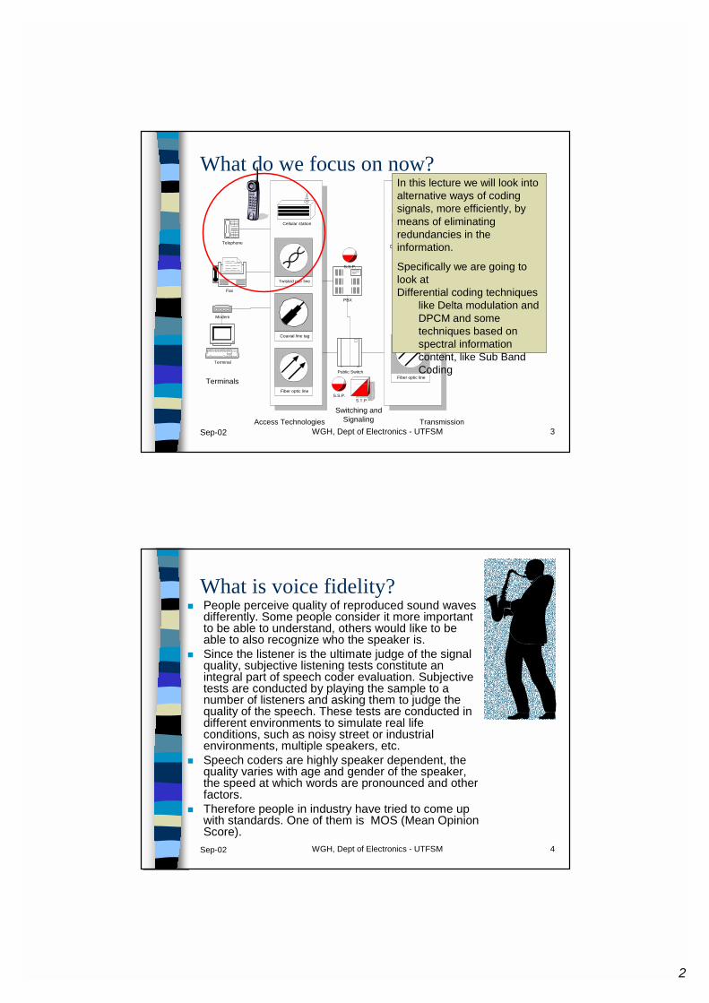
In this lecture we will look into alternative ways of coding signals, more efficiently, by means of eliminating redundancies in the information.
Specifically we are going to look at Differential coding techniques
like Delta modulation and DPCM and some techniques based on spectral information content, like Sub Band Coding
Sep-02 WGH, Dept of Electronics - UTFSM 4
What is voice fidelity?� People perceive quality of reproduced sound waves
differently. Some people consider it more important to be able to understand, others would like to be able to also recognize who the speaker is.
� Since the listener is the ultimate judge of the signal quality, subjective listening tests constitute an integral part of speech coder evaluation. Subjective tests are conducted by playing the sample to a number of listeners and asking them to judge the quality of the speech. These tests are conducted in different environments to simulate real life conditions, such as noisy street or industrial environments, multiple speakers, etc.
� Speech coders are highly speaker dependent, the quality varies with age and gender of the speaker, the speed at which words are pronounced and other factors.
� Therefore people in industry have tried to come up with standards. One of them is MOS (Mean Opinion Score).
3
Sep-02 WGH, Dept of Electronics - UTFSM 5
What is voice fidelity?� MOS considers 5 levels of satisfaction� 5 Excellent quality voice, no effort required.� 4 Good quality, no appreciable effort required� 3 Fair, moderate effort required� 2 Poor, considerable effort required� 1 Bad, no meaning understood with reasonable effort� Listener opinion tests use speech material in the form of sentences. These
sentences are typically high-quality, phonetically balanced recordings of both male and female speakers using diverse languages. Listeners judge the decompressed speech over the system being tested according to a given criterion. Listeners do not know what source they are listening to in any given speech sample. The most difficult conditions for voice coders to perform well is when the signal is transmitted from the mobile terminal to a base station, demodulated into an analog signal, which is then speech coded for retransmission as a digital signal over a landline or wireless link.
� Some general information on defining signal transmission considering quality issues can be found in:
� http://www.its.bldrdoc.gov/n3/video/pdf/t1a95102.pdf� http://www.net.com/products/narrowband/repository/white_papers/mos_wp/home.sht
ml� http://www.phon.ucl.ac.uk/home/mark/papers/nato97.pdf� http://www.cs.ucl.ac.uk/staff/awatson/avspn.html
Sep-02 WGH, Dept of Electronics - UTFSM 6
Voice Coders� One may broadly classify voice coders into 2 categories:
– Waveform coders strive to reproduce the time waveform of the speech signal as closely as possible. They are in principle independent of the source, and therefore may admit signals from different sources. Like signals from analog modems or faxes. Complexity is kept at a minimum and therefore the compression of the transmkission rate is not very high either.
– Vocoders, on the other hand exploit redundancies that are present in speech signals to eliminate them, thus reducing transmission speeds significantly. These are known typically as voice coders. Since they are highly source dependent. They may not work well for other kind of information.
4
Sep-02 WGH, Dept of Electronics - UTFSM 7
Classification of voice coders
Waveform coders Voice coders
LPC: Linear Predictive Coders
VocodersTime domain
Non differential
PCM
Differential
Delta
ADPCM
APC: Adaptive Predictive Coding
Frequency domain
SBC: Sub-Band Coding
ATC Adaptive Transform Coding
Sep-02 WGH, Dept of Electronics - UTFSM 8
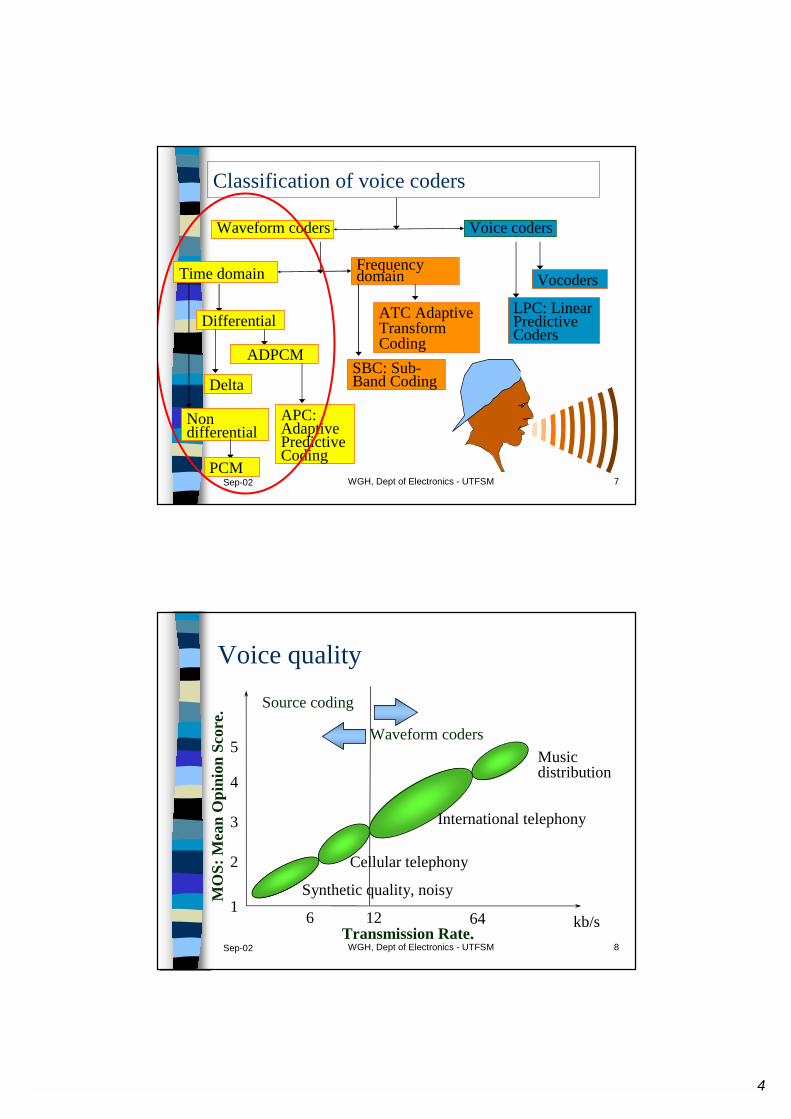
Voice quality
6 12 64 kb/sTransmission Rate..
1
2
3
4
5
MO
S: M
ean
Opi
nion
Scor
e.
Source coding
Waveform codersMusicdistribution
International telephony
Cellular telephony
Synthetic quality, noisy
5
Sep-02 WGH, Dept of Electronics - UTFSM 9
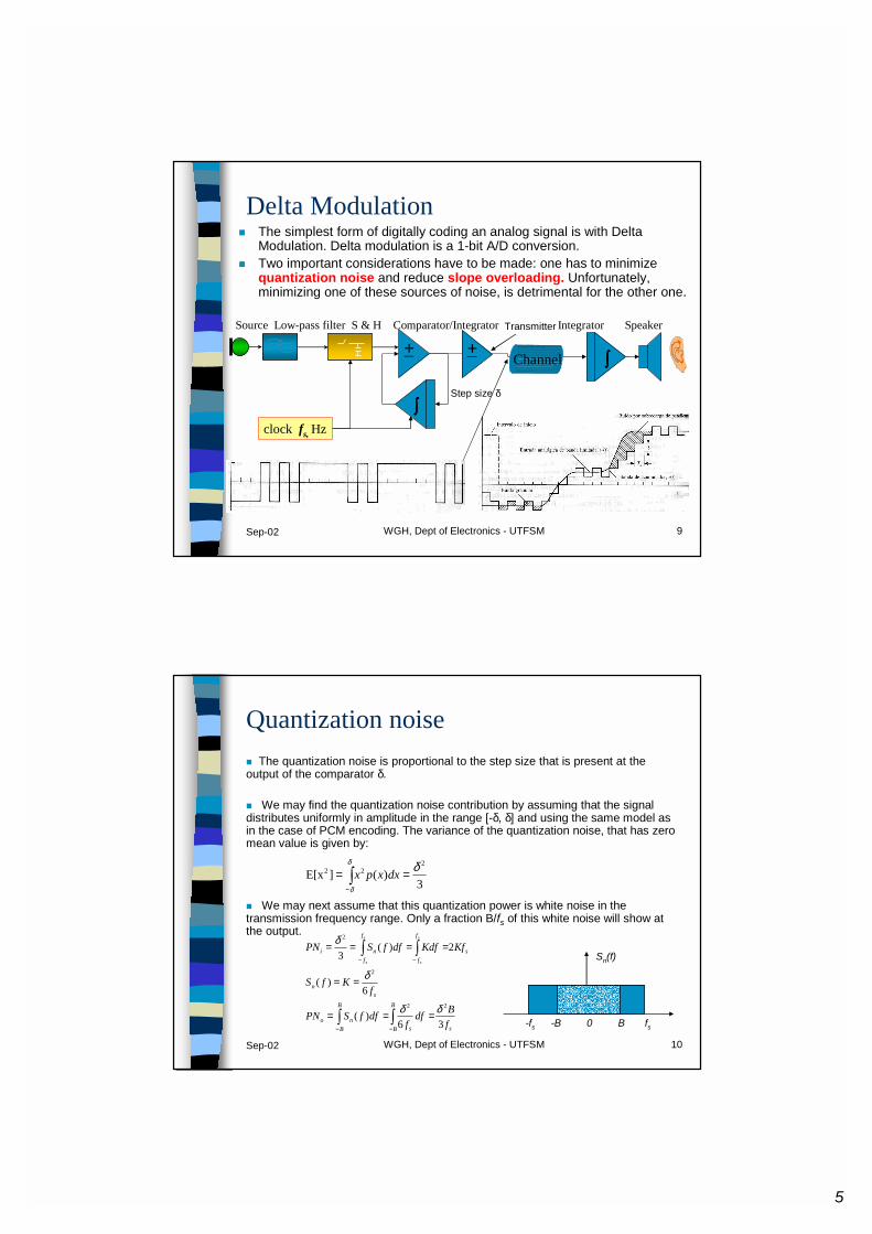
Delta Modulation� The simplest form of digitally coding an analog signal is with Delta
Modulation. Delta modulation is a 1-bit A/D conversion.� Two important considerations have to be made: one has to minimize
quantization noise and reduce slope overloading. Unfortunately, minimizing one of these sources of noise, is detrimental for the other one.
clock fs, Hz∫∫∫∫
Source Low-pass filter S & H Comparator/Integrator Integrator Speaker
+∫∫∫∫Channel
+Transmitter
Step size δ
Sep-02 WGH, Dept of Electronics - UTFSM 10
Quantization noise� The quantization noise is proportional to the step size that is present at the output of the comparator δ.
� We may find the quantization noise contribution by assuming that the signal distributes uniformly in amplitude in the range [-δ, δ] and using the same model as in the case of PCM encoding. The variance of the quantization noise, that has zero mean value is given by:
� We may next assume that this quantization power is white noise in the transmission frequency range. Only a fraction B/fs of this white noise will show at the output.
3)(]E[x
222 δδ
δ
== ∫−
dxxpx
s
B
B s
B
Bno
sn
s
f
f
f
fni
fBdf
fdffSPN
fKfS
KfKdfdffSPNs
s
s
s
36)(
6)(
2)(3
22
2
2
δδ
δ
δ
∫∫
∫∫
−−
−−
===
==
====
-fs -B 0 B fs
Sn(f)
6
Sep-02 WGH, Dept of Electronics - UTFSM 11
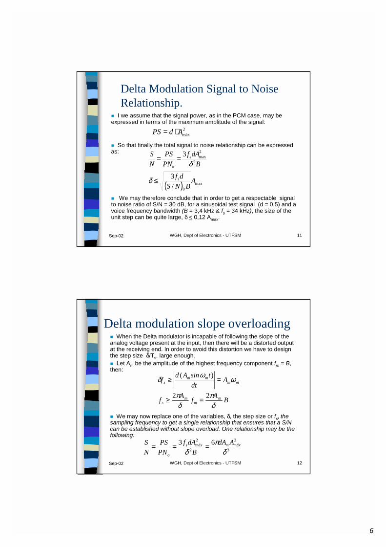
Delta Modulation Signal to Noise Relationship.
� I we assume that the signal power, as in the PCM case, may be expressed in terms of the maximum amplitude of the signal:
� So that finally the total signal to noise relationship can be expressed as:
� We may therefore conclude that in order to get a respectable signal to noise ratio of S/N = 30 dB, for a sinusoidal test signal (d = 0,5) and a voice frequency bandwidth (B = 3,4 kHz & fs = 34 kHz), the size of the unit step can be quite large, δ < 0,12 Amax.
2máxAdPS ⋅=
( ) max0
2
2max
/3
3
ABNS
df
BdAf
PNPS
NS
s
s
o
≤
==
δ
δ
Sep-02 WGH, Dept of Electronics - UTFSM 12
Delta modulation slope overloading� When the Delta modulator is incapable of following the slope of the analog voltage present at the input, then there will be a distorted output at the receiving end. In order to avoid this distortion we have to design the step size δ/Ts, large enough. � Let Am be the amplitude of the highest frequency component fm = B, then:
� We may now replace one of the variables, δ, the step size or fs, the sampling frequency to get a single relationship that ensures that a S/N can be established without slope overload. One relationship may be the following:
BAfAf
Adt
tsinAdf
mm
ms
mmmm
s
δπ
δπ
ωωδ
22
)(
=≥
=≥
3
2
2
2 63δ
πδ
máxmmáxs
o
AdAB
dAfPNPS
NS ===

7
Sep-02 WGH, Dept of Electronics - UTFSM 13
Delta modulation performanceThis figure is not related to the previously derived formula, but it shoes clearly that slope overloading and quantization (granular) noise are 2 parameters that affect Delta modulation performance.
Sep-02 WGH, Dept of Electronics - UTFSM 14
Delta modulation versus PCM
8
Sep-02 WGH, Dept of Electronics - UTFSM 15
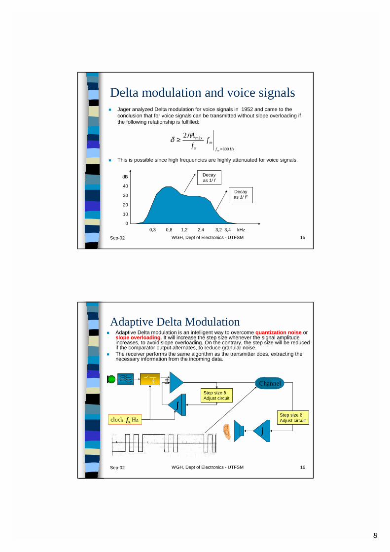
Delta modulation and voice signals� Jager analyzed Delta modulation for voice signals in 1952 and came to the
conclusion that for voice signals can be transmitted without slope overloading if the following relationship is fulfilled:
� This is possible since high frequencies are highly attenuated for voice signals.
Hzfm
sm
ffA
800
máx2
=
≥ πδ
0,3 0,8 1,2 2,4 3,2 3,4 kHz
dB
40
30
20
10
0
Decay as 1/ f2
Decay as 1/ f
Sep-02 WGH, Dept of Electronics - UTFSM 16
Adaptive Delta Modulation� Adaptive Delta modulation is an intelligent way to overcome quantization noise or
slope overloading. It will increase the step size whenever the signal amplitude increases, to avoid slope overloading. On the contrary, the step size will be reduced if the comparator output alternates, to reduce granular noise.
� The receiver performs the same algorithm as the transmitter does, extracting the necessary information from the incoming data.
clock fs, Hz
∫∫∫∫
+ Channel
∫∫∫∫
Step size δAdjust circuit
Step size δAdjust circuit

9
Sep-02 WGH, Dept of Electronics - UTFSM 17
Adaptive Delta modulation, also known as CVSD: Continuously Variable Slope Delta modulation
� Motorola has developed the VLSI circuit MC 3418 that increases/reduces the step size :of the modulator in discrete amounts, dpending on the informnation of the last 4 bits that have entered the encoder.
� Data sequence number of 1’s in dequence in last 4 bits step size� X X 01 1 δ� X 0 1 1 2 δ� 0 1 1 1 3 2δ� 1 1 1 1 4 4δ
� When the sampling rate of this circuit is set to 38 kb/s, then the S/N = 30 dB for voice signals.
Sep-02 WGH, Dept of Electronics - UTFSM 18
DPCM:Differential Pulse Code Modulation
� ADPCM is used today in the DECT and CT2 standard for wireless telephony. It provides international voice transmission quality and compatibility with modem and fax signals.
� Usually a voice signal is PCM encoded first, then a special PCM to ADPCM circuit is used to achieve the desired encoding. Of course, both encoding blocks may also be built into a single chip.
If the signal to the left is encoded as a PCM signal, then 4 bits would be needed to encode it. The encoded signal would be 1011 1101 1110 1100 1011 1000
A = 5 6 4 3 0
tiempo• DPCM permits a reduction of the transmission rate from 64kb/s to 48kb/s• ADPCM allows for an even bigger redution. It may be 32kb/s or 16 kb/s
Instead, if the same signal would be DPCM encoded, then the bit sequence to be transmitted would be (MSB is sign bit)110 101 010 001 011
10
Sep-02 WGH, Dept of Electronics - UTFSM 19
Tarea
� Determine si usted escogería un sistema PCM o DM para transmitir información de audio (ancho de banda nominal 15 kHz) que se distribuye uniformemente en amplitud, de tal modo que la relación señal a ruido en el extremo receptor sea al menos de 36 dB, suponiendo que en ambos casos se transmiten pulsos NRZ en forma polar por un canal de ancho de banda B (criterio de ancho de banda de primer lóbulo), igual para ambos casos, y que la potencia media de transmisión ha de ser idéntica en ambos casos. En el caso de PCM suponga que la tasa de muestreo es 1,2 veces la tasa mínima de muestreo (tasa de Nyquist) y que se usa cuantización uniforme. En DM suponga que la amplitud de la máxima frecuencia es 0,02 veces la amplitud máxima de la señal. Suponga que el canal transmite sin errores los pulsos.
Sep-02 WGH, Dept of Electronics - UTFSM 20
WiLL: Wireless Local Loop� The WiLL solution was originally thought of as a telephone service
solution. Usually it is very expensive to connect a new subscriber to the telephone plant when there is no cabling available.
� The “last mile” problem is one where it is very expensive to provide telephone service by wiring the local loop to the customer premises.
� It was considered that the wireless solution would considerably reduce the connection cost and additionally provide telephone service providers with an efficient “plug and play” type solution.
� It was also considered to be the ideal solution to provide coverage to mobile terminals of pedestrian users.
� Finally in some underdeveloped countries, wires are stolen.� It turns out that wireless connections were not an issue for
developed countries, where the wiring is already installed.� For underdeveloped countries there were not enough resources to
even implement the wireless solution, while the connection cost remained substantially the same
11
Sistemas de Comunicaciones Personales Inalámbricas
Juan Pablo Gómez L.04 de Mayo de 1999
Sep-02 WGH, Dept of Electronics - UTFSM 22
Sistemas de comunicaciones Personales Inalámbricos
� Objetivos:� Proveer de acceso telefónico en cualquier lugar a
cualquier instante.� Concepto de movilidad
SistemasCelulares Cordless
� Largo alcance (handoff-roaming)� baja tasa de Tx
(capacidad disponible)� Interconexión
� Corto alcance (cientos de metros)� alta tasa de Tx (pequeño radio de celda)� Entes individuales
12
Sep-02 WGH, Dept of Electronics - UTFSM 23
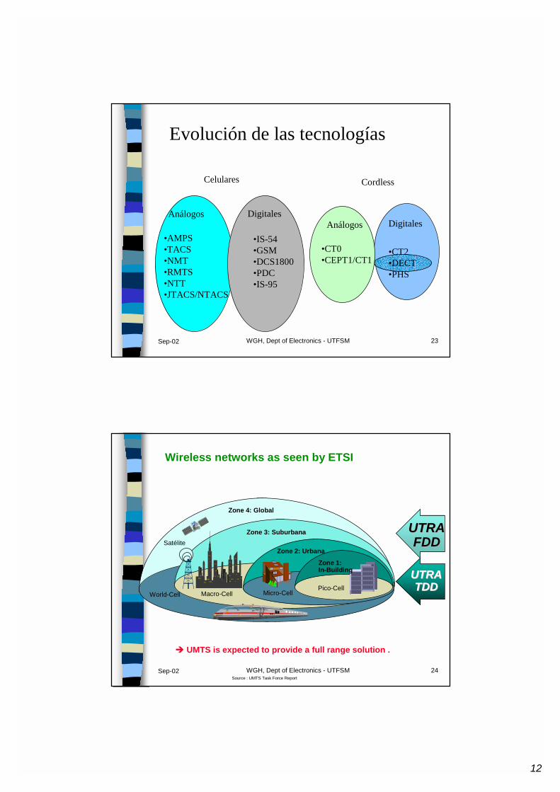
Evolución de las tecnologías
Celulares Cordless
Análogos DigitalesAnálogos Digitales
•AMPS•TACS•NMT•RMTS•NTT•JTACS/NTACS
•IS-54•GSM•DCS1800•PDC•IS-95
•CT0•CEPT1/CT1
•CT2•DECT•PHS
Sep-02 WGH, Dept of Electronics - UTFSM 24
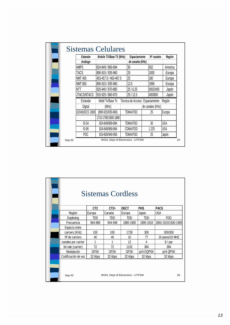
Wireless networks as seen by ETSI
Source : UMTS Task Force Report
� UMTS is expected to provide a full range solution .
Zone 4: Global
SatéliteZone 3: Suburbana
Zone 2: Urbana
Zone 1: In-Building
Macro-CellPico-Cell
Micro-CellWorld-Cell
UTRAUTRATDDTDD
UTRAUTRAFDDFDD
13
Sep-02 WGH, Dept of Electronics - UTFSM 25
Estandar Mobile TX/Base TX (MHz) Espaciamiento Nº canales RegiónAnálogo de canales (KHz)
AMPS 824-849 / 869-894 30 832 AmericaTACS 890-915 / 935-960 25 1000 EuropaNMT 450 453-457.5 / 463-467.5 25 180 EuropaNMT 900 890-915 / 935-960 12.5 1999 EuropaNTT 925-940 / 870-885 25 / 6.25 600/2400 JapónJTACS/NTACS 915-925 / 860-870 25 / 12.5 400/800 Japón
Sistemas Celulares
Estandar Mobil Tx/Base Tx Tecnica de Acceso Espaciamiento RegiónDigital (MHz) de canales (KHz)
(GSM)/DCS 1800 (890-915/935-960) TDMA/FDD 25 Europa1710-1785/1805-1880
IS-54 824-849/869-894 TDMA/FDD 30 USAIS-95 824-849/869-894 CDMA/FDD 1.225 USAPDC 810-826/940-956 TDMA/FDD 25 Japón
Sep-02 WGH, Dept of Electronics - UTFSM 26
Sistemas Cordless
CT2 CT2+ DECT PHS PACSRegión Europa Canada Europa Japan USA
Duplexing TDD TDD TDD TDD FDDFrecuencia 864-868 944-948 1880-1900 1895-1918 1850-1910/1930-1990
Especio entrecarriers (KHz) 100 100 1728 300 300/300Nº de carriers 40 40 10 77 16 pares/10 MHZ
canales por carrier 1 1 12 4 8 / parbit rate (carrier) 72 72 1152 384 384
Modulación GFSK GFSK GFSK pi/4 DQPSK pi/4 QPSKCodificación de voz 32 kbps 32 kbps 32 kbps 32 kbps 32 kbps

14
Sep-02 WGH, Dept of Electronics - UTFSM 27
Wireless Local Loop
Sistemas WLL por tecnología DECT 27%
US TDMA 22%
Analog cellular 17%
PHS 13%
CDMA 10%
CT-2 3%
GSM 2%
otros 6%
Sep-02 WGH, Dept of Electronics - UTFSM 28
Concepto Funcional DECT
� El DECT es un subsistema microcelular de teléfonos inalámbricos, que puede ser integrado o conectado a una Central de Conmutación Privada Automática, (PABX) o una Red Pública de Conmutación Telefónica, (PSTN).
� DECT consta de cinco entidades funcionales:� PH: Portable Handset� RFP: Radio Fixed Part� CC: Cluster Controller� Network-specific Interface Unit� Servicios suplementarios

15
Sep-02 WGH, Dept of Electronics - UTFSM 29
CCCC
CCCC
RFPRFP
RFPRFP
RFPRFP
RFPRFP
RFPRFP
RFPRFP
PSTNPSTN
ruteamiento de llam
adaruteam
iento de llamada
ServiciosServiciosSuplementariosSuplementarios
Dominio Norma DECTDominio Norma DECTSistema Fijo DECTSistema Fijo DECT
PHPH
PHPH
FAXFAX
CTACTA
Concepto Funcional DECTConcepto Funcional DECT
Sep-02 WGH, Dept of Electronics - UTFSM 30
Aplicaciones DECT
Aplicaciones
Wireless Local Loop
Redes Inalámbricas
16
Sep-02 WGH, Dept of Electronics - UTFSM 31
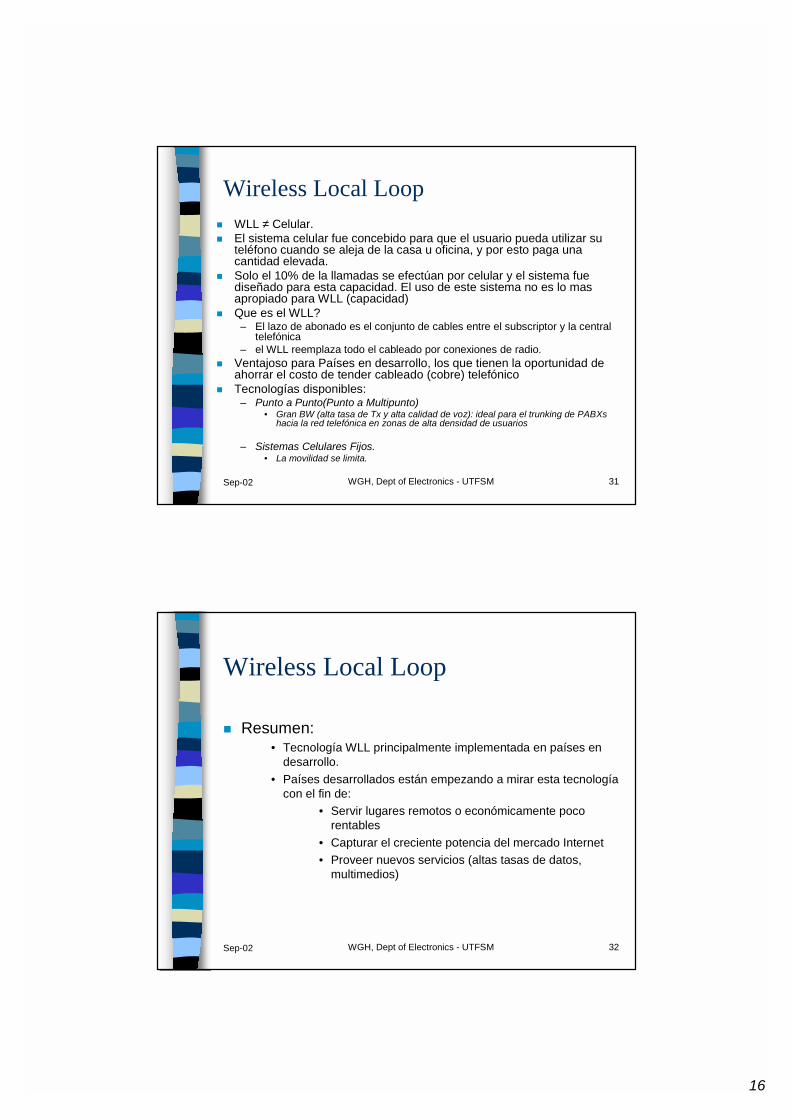
Wireless Local Loop� WLL ≠ Celular.� El sistema celular fue concebido para que el usuario pueda utilizar su
teléfono cuando se aleja de la casa u oficina, y por esto paga una cantidad elevada.
� Solo el 10% de la llamadas se efectúan por celular y el sistema fue diseñado para esta capacidad. El uso de este sistema no es lo mas apropiado para WLL (capacidad)
� Que es el WLL?– El lazo de abonado es el conjunto de cables entre el subscriptor y la central
telefónica– el WLL reemplaza todo el cableado por conexiones de radio.
� Ventajoso para Países en desarrollo, los que tienen la oportunidad de ahorrar el costo de tender cableado (cobre) telefónico
� Tecnologías disponibles:– Punto a Punto(Punto a Multipunto)
• Gran BW (alta tasa de Tx y alta calidad de voz): ideal para el trunking de PABXshacia la red telefónica en zonas de alta densidad de usuarios
– Sistemas Celulares Fijos.• La movilidad se limita.
Sep-02 WGH, Dept of Electronics - UTFSM 32
Wireless Local Loop
� Resumen:• Tecnología WLL principalmente implementada en países en
desarrollo.• Países desarrollados están empezando a mirar esta tecnología
con el fin de:• Servir lugares remotos o económicamente poco
rentables • Capturar el creciente potencia del mercado Internet• Proveer nuevos servicios (altas tasas de datos,
multimedios)

17
Sep-02 WGH, Dept of Electronics - UTFSM 33
Aplicaciones DECT
Aplicaciones
Wireless Local Loop
Redes Inalámbricas
Sep-02 WGH, Dept of Electronics - UTFSM 34
Redes de datos Inalámbricas
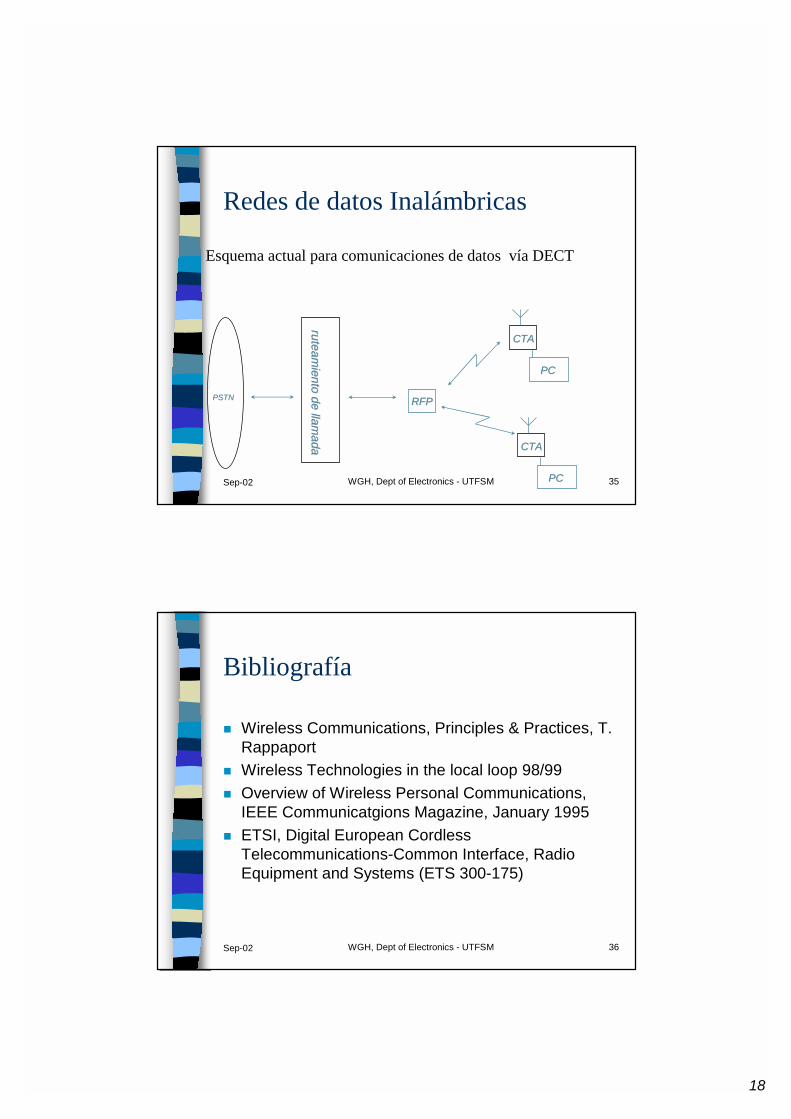
� El formato DECT esta capacitado para otorgar servicios de datos a terminales móviles (Servicios RDSI).
� Aplicaciones punto a punto� No se ha desarrollado un esquema de red dentro del
área de una celda DECT, que permita a usuarios interconectarse entre ellos utilizando esta interfaz.
18
Sep-02 WGH, Dept of Electronics - UTFSM 35
Redes de datos Inalámbricas
Esquema actual para comunicaciones de datos vía DECT
RFPRFPPSTNPSTN
ruteamiento de llam
adaruteam
iento de llamada CTACTA
PCPC
CTACTA
PCPC
Sep-02 WGH, Dept of Electronics - UTFSM 36
Bibliografía
� Wireless Communications, Principles & Practices, T. Rappaport
� Wireless Technologies in the local loop 98/99� Overview of Wireless Personal Communications,
IEEE Communicatgions Magazine, January 1995� ETSI, Digital European Cordless
Telecommunications-Common Interface, Radio Equipment and Systems (ETS 300-175)
19
Sep-02 WGH, Dept of Electronics - UTFSM 37
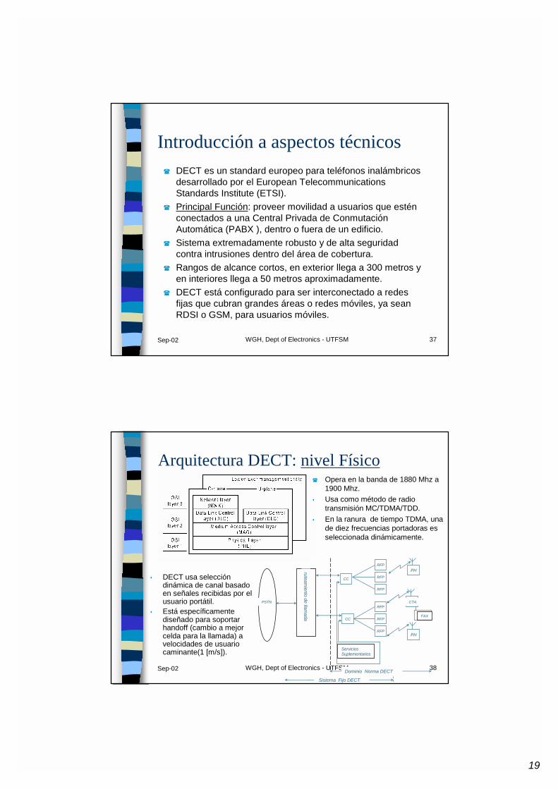
Introducción a aspectos técnicos� DECT es un standard europeo para teléfonos inalámbricos
desarrollado por el European TelecommunicationsStandards Institute (ETSI).
� Principal Función: proveer movilidad a usuarios que estén conectados a una Central Privada de Conmutación Automática (PABX ), dentro o fuera de un edificio.
� Sistema extremadamente robusto y de alta seguridad contra intrusiones dentro del área de cobertura.
� Rangos de alcance cortos, en exterior llega a 300 metros y en interiores llega a 50 metros aproximadamente.
� DECT está configurado para ser interconectado a redes fijas que cubran grandes áreas o redes móviles, ya sean RDSI o GSM, para usuarios móviles.
Sep-02 WGH, Dept of Electronics - UTFSM 38
Arquitectura DECT: nivel Físico
CCCC
CCCC
RFPRFP
RFPRFP
RFPRFP
RFPRFP
RFPRFP
RFPRFP
PSTNPSTN
ruteamiento de llam
adaruteam
iento de llamada
ServiciosServiciosSuplementariosSuplementarios
Dominio Norma DECTDominio Norma DECT
Sistema Fijo DECTSistema Fijo DECT
PHPH
PHPH
FAXFAX
CTACTA
� Opera en la banda de 1880 Mhz a 1900 Mhz.
� Usa como método de radio transmisión MC/TDMA/TDD.
� En la ranura de tiempo TDMA, una de diez frecuencias portadoras es seleccionada dinámicamente.
� DECT usa selección dinámica de canal basado en señales recibidas por el usuario portátil.
� Está específicamente diseñado para soportar handoff (cambio a mejor celda para la llamada) a velocidades de usuario caminante(1 [m/s]).
20
Sep-02 WGH, Dept of Electronics - UTFSM 39
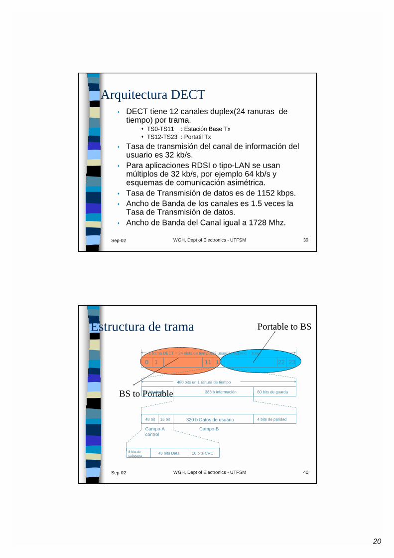
Arquitectura DECT� DECT tiene 12 canales duplex(24 ranuras de
tiempo) por trama.� TS0-TS11 : Estación Base Tx� TS12-TS23 : Portatil Tx
� Tasa de transmisión del canal de información del usuario es 32 kb/s.
� Para aplicaciones RDSI o tipo-LAN se usan múltiplos de 32 kb/s, por ejemplo 64 kb/s y esquemas de comunicación asimétrica.
� Tasa de Transmisión de datos es de 1152 kbps. � Ancho de Banda de los canales es 1.5 veces la
Tasa de Transmisión de datos.� Ancho de Banda del Canal igual a 1728 Mhz.
Sep-02 WGH, Dept of Electronics - UTFSM 40
BS to Portable
Portable to BSEstructura de trama
0 1 11 12 22 231 trama DECT = 24 slots de tiempo(12 usuarios duplex) = 10ms
32 bit sincro
480 bits en 1 ranura de tiempo
388 b información 60 bits de guarda
8 bits decabecera 40 bits Data 16 bits CRC
48 bit 16 bit 4 bits de paridad
Campo-Acontrol
Campo-B
320 b Datos de usuario
21
Sep-02 WGH, Dept of Electronics - UTFSM 41
Arquitectura DECT
� nivel Control de Enlace de Datos:� Provee enlaces de datos confiables a la capa de red.� Divide los canales físicos y lógicos dentro de los slots
de tiempo para cada usuario.� Provee detección y/o corrección de errores para
cada canal (según los requerimientos).
Sep-02 WGH, Dept of Electronics - UTFSM 42
Arquitectura DECT
� Nivel de Red:� Principal nivel de señalización de DECT está basado
en protocolos RDSI (nivel 3) y GSM.� Provee control de llamadas y servicios de circuitos-
conmutados seleccionado de uno de los servicios DLC, como mensajes orientados a la conexión y administración móvil.
22
Sep-02 WGH, Dept of Electronics - UTFSM 43
DECT Radio Enlace
� Codificación de Voz:� la voz se codifica en formato ADPCM a 32 kbps� Codificación de Canal:� no se utiliza codificación de canal (existe FH y
ademas se utiliza en ambientes indoorprincipalmente).
� canal de control ocupa CRC16� Modulación:� DECT usa técnica de modulación GMSK (Gaussian
Minimum Shift Keying).
Sep-02 WGH, Dept of Electronics - UTFSM 44
DECT Radio Enlace
� Diversidad de Antena:� la diversidad espacial sólo es implementada en las
RFPs (estación base) pudiendo utilizarse 2 antenas.� la mejor antena para la ranura de tiempo es
seleccionada de acuerdo a los niveles de potencia, interferencia o Tasa de Error de Bit (BER)
23
Sep-02 WGH, Dept of Electronics - UTFSM 45
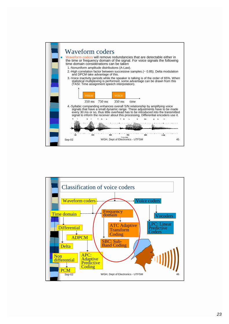
Waveform coders� Waveform coders will remove redundancies that are detectable either in
the time or frequency domain of the signal. For voice signals the following time domain considerations can be taken1.-Nonuniform amplitude distributions (A-Law).2.-High correlation factor between successive samples.(~ 0.85). Delta modulation
and DPCM take advantage of this.3.-Voice inactivity periods while the speaker is talking is of the order of 65%. When
statistical multiplexing is performed, some advantage can be drawn from this (TASI: Time assignment speech interpolation).
4.-Syllabic companding enhances overall S/N relationship by amplifying voice signals that have a small dynamic range. These adjustments have to be made every 30 ms or so, thus little overhead has to be introduced into the transmitted signal to inform the receiver about this processing. Differential encoders use it.
voice voice350 ms 750 ms 350 ms time
Sep-02 WGH, Dept of Electronics - UTFSM 46
Classification of voice coders
Waveform coders Voice coders
LPC: Linear Predictive Coders
VocodersTime domain
Non differential
PCM
Differential
Delta
ADPCM
APC: Adaptive Predictive Coding
Frequency domain
SBC: Sub-Band Coding
ATC Adaptive Transform Coding
24
Sep-02 WGH, Dept of Electronics - UTFSM 47
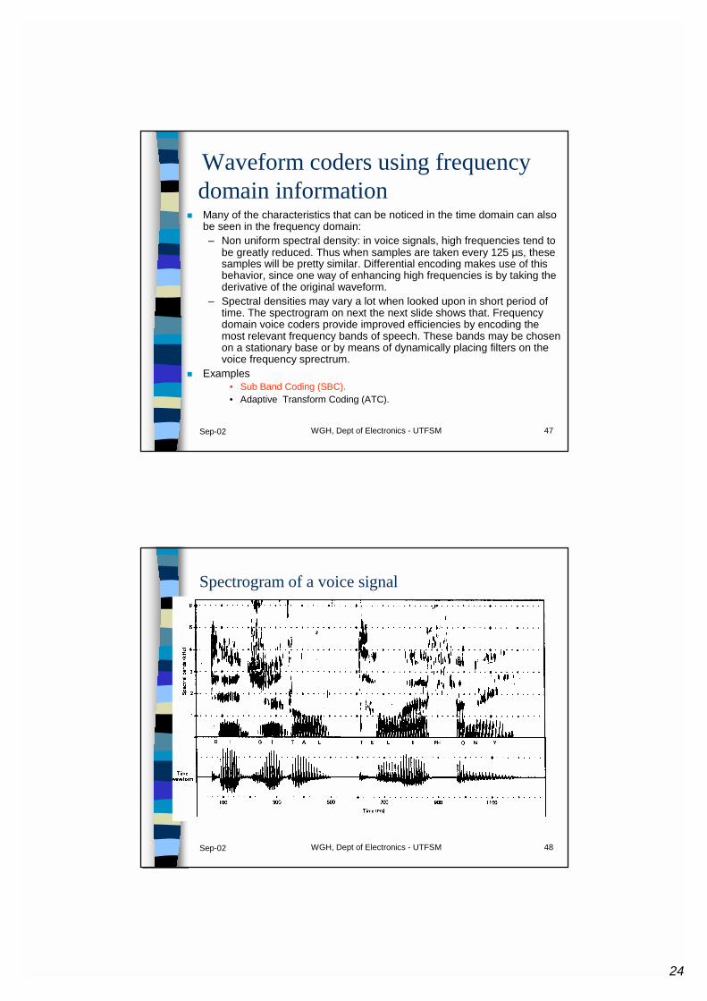
Waveform coders using frequency domain information
� Many of the characteristics that can be noticed in the time domain can also be seen in the frequency domain:– Non uniform spectral density: in voice signals, high frequencies tend to
be greatly reduced. Thus when samples are taken every 125 µs, these samples will be pretty similar. Differential encoding makes use of this behavior, since one way of enhancing high frequencies is by taking the derivative of the original waveform.
– Spectral densities may vary a lot when looked upon in short period of time. The spectrogram on next the next slide shows that. Frequency domain voice coders provide improved efficiencies by encoding the most relevant frequency bands of speech. These bands may be chosen on a stationary base or by means of dynamically placing filters on the voice frequency sprectrum.
� Examples• Sub Band Coding (SBC).• Adaptive Transform Coding (ATC).
Sep-02 WGH, Dept of Electronics - UTFSM 48
Spectrogram of a voice signal
25
Sep-02 WGH, Dept of Electronics - UTFSM 49
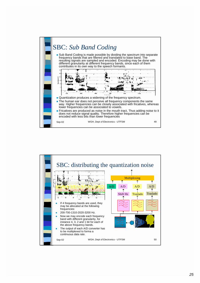
SBC: Sub Band Coding� Sub Band Coding is made possible by dividing the spectrum into separate
frequency bands that are filtered and translated to base band. The resulting signals are sampled and encoded. Encoding may be done with different granularity at different frequency bands, since each of them contributes in its own way to the speech formants.
� Quantization produces a widening of the frequency spectrum.� The human ear does not perceive all frequency components the same
way. Higher frequencies can be closely associated with fricatives, whereas lower frequencies can be associated to vowels.
� Fricatives are produced as noise in the mouth tract, Thus adding noise to it does not reduce signal quality. Therefore higher frequencies can be encoded with less bits than lower frequencies
Sep-02 WGH, Dept of Electronics - UTFSM 50
SBC: distributing the quantization noise
� If 4 frequency bands are used, they may be allocated at the following frequencies:
� 200-700-1310-2020-3200 Hz.� Now we may encode each frequency
band with different granularity, for instance 4, 3, 2 and 1 bit for each of the above frequency bands.
� The output of each A/D converter has to be multiplexed to forma a continuous data rate.
Shift Hz
A/D
Traslado
A/D
Traslado
A/D
Multiplexing
A/D
26
Sep-02 WGH, Dept of Electronics - UTFSM 51
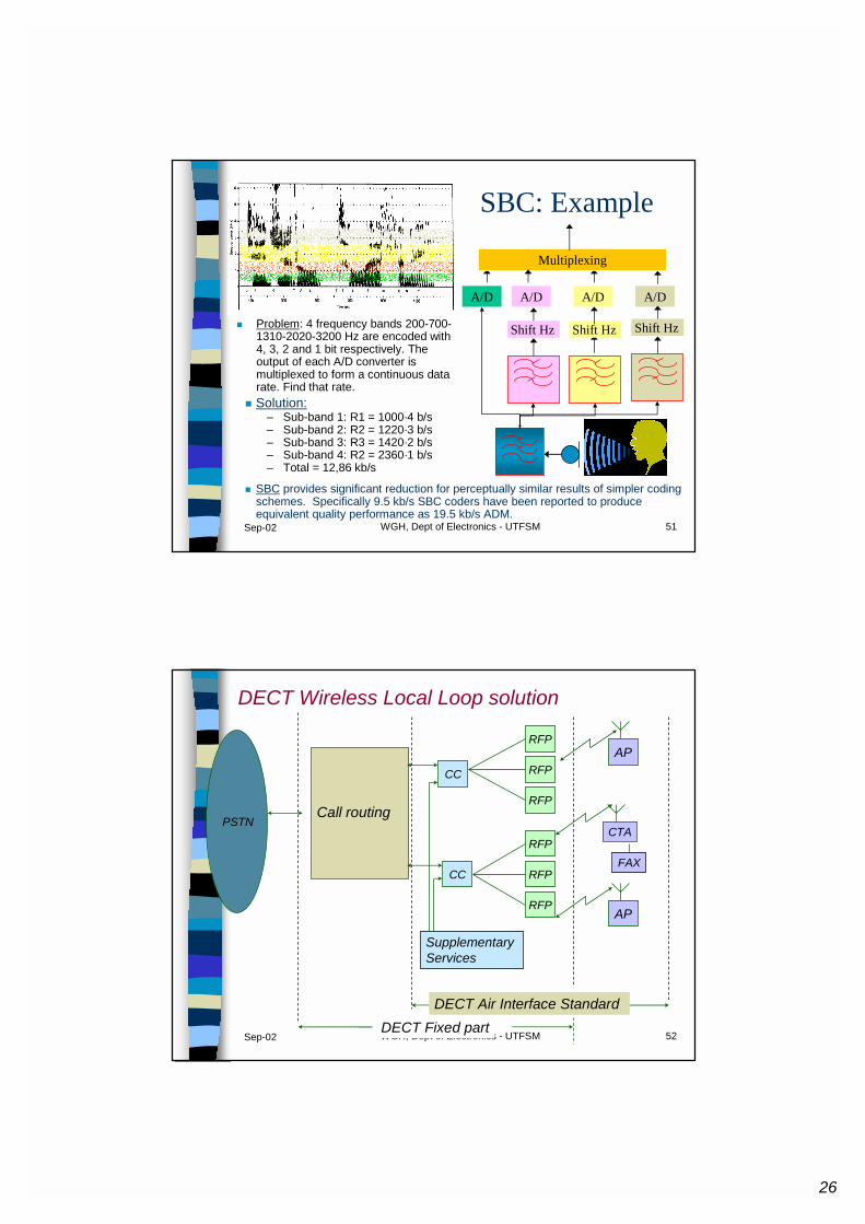
SBC: Example
� Problem: 4 frequency bands 200-700-1310-2020-3200 Hz are encoded with 4, 3, 2 and 1 bit respectively. The output of each A/D converter is multiplexed to form a continuous data rate. Find that rate.
Shift Hz
A/D
Shift Hz
A/D
Shift Hz
A/D
Multiplexing
A/D
� Solution:– Sub-band 1: R1 = 1000·4 b/s– Sub-band 2: R2 = 1220·3 b/s– Sub-band 3: R3 = 1420·2 b/s– Sub-band 4: R2 = 2360·1 b/s– Total = 12,86 kb/s
� SBC provides significant reduction for perceptually similar results of simpler coding schemes. Specifically 9.5 kb/s SBC coders have been reported to produce equivalent quality performance as 19.5 kb/s ADM.
Sep-02 WGH, Dept of Electronics - UTFSM 52
PSTN
CC
CC
RFP
RFP
RFP
RFP
RFP
RFP
Call routing
SupplementaryServices
DECT Fixed part
AP
AP
FAX
CTA
DECT Wireless Local Loop solution
DECT Air Interface Standard


![Pdh Sdh Presentation[1]](https://img.pdfslide.net/doc/110x75/5571fe4049795991699af731/pdh-sdh-presentation1.jpg)