Embed Size (px)
Citation preview
UNIVERSITI PUTRA MALAYSIA
APPLICATION OF FOCUS IMPROVEMENT TO REDUCE NON-STICK ON PAD PROBLEM IN IC PACKAGING
SIVAKUMAR A/L DHAR MALINGAM.
FK 2004 8
APPLICATION OF FOCUS IMPROVEMENT TO REDUCE NON-STICK ON PAD PROBLEM IN IC PACKAGING
SIVAKUMAR A& DHAR MALINGAM
Thesis Submitted to the School of Graduate Studies, Universiti Putra Malaysia in Fulfilment of the Requirements for the
Degree of Master of Science
February 2004

This work is dedicated to my beloved Parents, brother, sister and niece
Abstract of thesis presented to the Senate of Universiti Putra Malaysia in fulfilment of requirements for the degree of Master of Science
APPLICATION OF FOCUS IMPROVENIENT TO REDUCE NON-STICK ON PAD PROBLEM IN IC PACKAGING
BY
SIVAKUMAR A/L DHAR MALINGAM
February2004
Chairman
FacuIty
Associate Professor Napsiah Ismail, Ph.D.
Engineering
Total Productive Maintenance (TPM) methodologies are ~ised to eliminate profit loss
or waste due to equipment failure or defect. TPM is designed to get maximum
efficiency from the equipment while creating a satisfactory working environment. In
Motorola, Selangor yield improvement had been an important agenda. One of the
TPM pillar which is Focus Improvement activity is designed to minimize targeted
losses that had been caref~illy measured and evaluated, was employed to improve
yield in front-end assembly. The top three yield lost in parts per million (ppm) were
contributed by the following defects in descending order: Non Stick on Pad (2715
ppm), chip and crack (782 ppm) and missing wire (687 ppni). The team focused on
Non Stick on Pad (NSOP). which was the top yield lost contributor. NSOP was due
to: floating die, bonded ball small in size, foreign matter on pad and glassifications to
say a few. Floating die contributed 48% of the NSOP dei'ect. In this project detailed

explanation on how one of TPM tools, which is Focus lmprovement activity used to
reduce Non Stick on Pad due to floating die is shown. Upon identifying the root cause
of die floating which was due to no support and weakness in the vacuum system
actions were taken to eliminate and to control the identified causes. As a result NSOP
due to floating die had been reduced from 1300 parts per million (ppm) to 650 ppm a
reduction of 50% within one year.
Abstrak tesis yang dikemukakan kepada Senat Universiti Putra Malaysia sebagai memenuhi keperluan untuk ijazah Master Sains
PENGGUNAAN KAED
Oleh
SIVAKUMAR AIL D ALINGA
Pengerusi :
Fakulti
Profesor Madya Napsiah Ismail, Ph.D.
Kejuruteraan
Senggaraan Produktif Menyeluruh atau ringkasanya I'PM adalah ~lntuk
nlenghapuskan kerugian atau pembaziran yang disebabkan oleh kegagalan dan
kecacatan peralatan. TPM bertujuan untuk memperolehi kecekapan maksimum pada
peralatan di samping mempertingkatkan kejayaan syarikat dan menjadikan ternpat
pekerjaan satu tempat yang dapat memuaskan hati pekerja. Motorola, Selangor telah
mula menumpukan sepenuh perhatian dalam meningkatkan kualiti. Kaedah
Peningkatan Penumpuan atau ringkasannya FI yang merupakan salah satu tunggak
TPM bertujuan untuk rnengurangkan kemerosotan kualiti yang dikenal pasti dan telah
diukur dengan teliti digunakan untuk meningkatkan Iaaliti barangan di pemasangan
"front-end". Tiga punca tertinggi kemerosotan kualiti dalam unit per juta (ppm)
adalah disebabkan oleh: "Non Stick On Pad" (2715 ppm), "chip dan crack" (782
ppm) dan "missing wire" (687 ppm). Penumpuan diberikan kepada "Non Stick On
Pad" (NSOP) memandangkan ia adalah punca kemerosotan kualiti yang tertinggi.
Beberapa contoh punca NSOP adalah : unit terapung, saiz bola yang kecil, bendasing
pada pad dan kaca pada pad. 48% NSOP adalah disebabkan oleh unit terapung.
Projek ini menunjukkan bagaimana FI digunakan untuk mengurangkan NSOP
disebabkan oleh unit terapung. Setelah mengenalpasti punca unit terapung yang
disebabkan ketiadaan asas penahan dan kelemahan sistem vakum langkah-langkah
telah diambil untuk menghapuskan dan mengawalselia punca tersebut. Hasilnya
kaedah ini berjaya meningkatkan kualiti dengan mengurangkan NSOP pada unit
terapung daripada 1300 unit per juta (ppm) kepada 650 ppm; pengurangan sebanyak
50% dalam tempoh masa setahun.
ACKNOWLEDGEMENTS
An expression of appreciation is extended to my project Chairman, Associate
Professor Dr. Napsiah Ismail and member of Supervisory Committee, Associate
Professor Ir. Dr. Md. Yusof Ismail and Associate Professor Ir. Dr. Mohd Sapuan Salit
from the Department of Mechanical and Manufacturing, Unjversiti Putra Malaysia for
their guidance and advice throughout the duration of this study. Thank is also due to
Miss Caron Kee, my work supervisor for her feedbacks and suggestions for the
success of the project.
Special thanks to Front End Process I Equipment Manager, Miss G.K. Teh for
granting me the opportunity to conduct this project in the department. Sincere
appreciation is extended to Mr. CL Goh who had worked along with me to complete
this project.
Many thanks are expressed to all my friends especially Vasan Mariappan, Kumares
Wara Rao and Meenaloshini Satgunam for their moral support and encouragement in
making this project a success.
Finally, I wish to thank my dearest parents and family for their patience,
encouragement and support when it was most needed.
vii
I certify that an Examination Committee met on 3rd February 2004 to conduct the final examination of Sivakumar A/L Dhar Malingarn on his Master of Science thesis entitled "Application of Focus Improvement to Reduce Non- Stick on Pad Problem in IC Packaging" in accordance with Universiti Pertanian Malaysia (Higher Degree) Act 1980 and Universiti Pertanian Malaysia (Higher Degree) Regulations 198 1. The Committee recommends that the candidate be awarded the relevant degree. Members of the Examination Committee are as follows:
Wong Shaw Voon, Ph.D. Faculty of Engineering Universiti Putra Malaysia (Chairnian)
Napsiah Ismail, Ph.D. Associate Professor Faculty of Engineering Universiti Putra Malaysia (Member)
Ir. Md. Yusof Ismail, Ph.D. Associate Professor Faculty of Engineering Universiti Putra Malaysia (Member)
Ir. Mohd. Sapuan Salit, Ph.D. Associate Professor Faculty of Engineering Universiti Putra Malaysia (Member)
This thesis submitted to the Senate of Universiti Putra Malaysia has been accepted as fulfillment for the degree of Master of Science. The members of the supervisory committee are as follows:
Napsiah Ismail, Ph.D. Associate Professor Faculty of Engineering Universiti Putra Malaysia (Chairman)
Ir. Md. Yusof Ismail, Ph.D. Associate Professor Faculty of Engineering Universiti Putra Malaysia (Member)
Ir. Mohd Sapuan Salit, Ph.D. Associate Professor Faculty of Engineering Universiti Putra Malaysia (Member)
AINI IDERIS, Ph.D. ProfessorlDean School of Graduate Studies Universiti Putra Malaysia
Date: 0 9 APR 2004
DECLARATION
I hereby declare that the thesis is based on my original work except for the quotations and citations, which have been duly acknowledged. I also declare that it has not been previously or concurrently submitted for any other degree at UPM or other institutions.
/ SII'AKUMAR A/L DHAR MALINGAM
Date: 18 Mm-& 2-004
TABLE OF CONTENTS
DEDICATION ABSTRACT ABSTRAK ACKNOM'LEDGEMENTS APPROVAL DECLAR4TION LIST OF TABLES LIST OF FIGURES LIST OF ABBREVL4TIONS
CHAPTER
INTRODUCTIOhT 1.1 Introduction 1.2 Introduction to Wire Bonding
1.2.1 Ball Bonding Cycle 1.3 Problem Definition 1.4 Research Objective 1.5 Thesis Outline
LITERATURE REVIEW 2.1 Introduction 2.2 Definition of Total Productive Maintenance
2.2.1 More Definitions of TPM 2.3 M7hen and Where TPM Originate 2.4 TPM Pillars
2.4.1 Autonomous Maintenance 2.4.2 Focused lmprovement 2.4.3 Planned Maintenance 2.4.4 Quality Maintenance 2.4.5 Training 2.4.6 Office TPM 2.4.7 Safety and Environment 2.4.8 Initial Flow Control
2.5 Reasons for Choosing Total Productive Maintenance 2.6 Failure in Other Quality Programs 2.7 Overall Equipment Effectiveness 2.8 Success Stow of TPM
Page . . 11 . . . 111
V . .
V11 . . . Vlll
X . . .
X l l l
xiv xvi
2.8.1 company 1 : Barley-Davidson Motor Company, USA 2.8.2 Company 2: Eaton Corporation, Hydraulics Division, USA 42 2.8.3 Company 3: E.1 DuPont, USA 42 2.8.4 Company 4: Magnavox, USA 4 3 2.8.5 Company 5: Texas Instruments, USA 43 2.8.6 Company 6: Kodak, USA 44 2.8.7 Company 7: STM Crolles, USA 45
2.8.8 Company 8: Motorola, Phoenix 2.9 Other Companies Practicing TPM 2.10 Summary
METHODOLOGY 3.1 Introduction 3.2 Methodology
RESULTS AND DISCUSSIONS 4.1 Introduction 4.2 Results of Focus Improvement Implementation
CONCLUSIONS AND RECOMMENDATIONS 5 Introduction 5.2 Conclusions 5.3 Recommendations
APPENDICES
Appendix A: W-ire Bond Models Appendix B: One Point Lesson for Insert Cleaning ,4ppendix C: One Point Lesson for Changing Vacuum Tubing Appendix D: Autonomous Maintenance Standards for Operators Appendix E: Autonomous Maintenance Standards for Technicians
BIODATA OF THE AUTHOR
xii
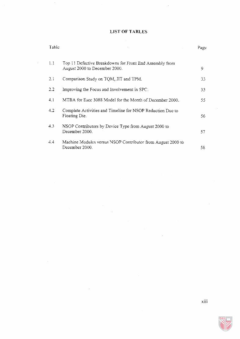
LIST OF TABLES
Table
Top 1 1 Defective Breakdowns for Front End Assembly from August 2000 to December 2000.
Comparison Study on TQM, JIT and TPM.
2.2 Improving the Focus and Involvement in SPC.
4.1 MTBA for Esec 3088 Model for the Month of December 2000.
Complete Activities and Timeline for NSOP Reduction Due to Floating Die.
M O P Contributors by Device Type from August 2000 to December 2000.
Machine Modules versus NSOP Conmbutor from August 2000 ro December 2000.
Page
... Xll l
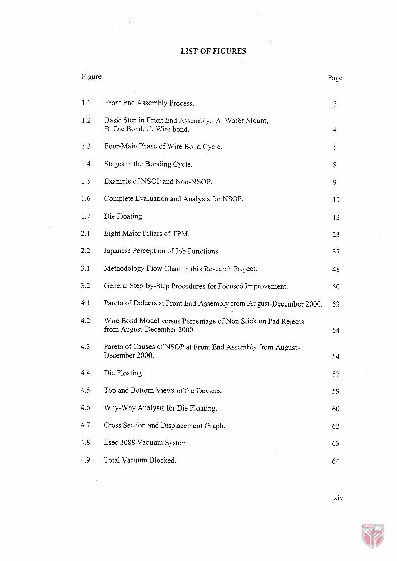
LIST OF FIGURES
Figure
Front End Assembly Process.
Basic Step in Front End Assembly: A. Wafer Mount, B. Die Bond, C. Wire bond.
Four-Main Phase of Wire Bond Cycle.
Stages in the Bonding Cycle.
Example of NSOP and Non-NSOP.
Complete Evaluation and Analysis for NSOP.
Die Floating.
Eight Major Piliars of TPM.
Japanese Perception of Job Functions.
Methodology Flow Chart in this Research Project.
3.2 General Step-by-step Procedures for Focused Improvement.
4.1 Pareto of Defects at Front End Assembly from August-December 2000
Wire Bond Model versus Percentage of Non Stick on Pad Rejects from August-December 2000.
Pareto of Causes of NSOP at Front End Assembly from August- December 2000.
Die Floating.
Top and Bottom Views of the Devices.
Why-Why Analysis for Die Floating.
Cross Section and Displacement Graph.
Esec 3088 Vacuum System.
Total Vacuum Blocked.
Page
3
xiv
Partial Vacuum Blocked.
Die Bottom View.
Die Tilt due to Pivoting Effect.
Islands to Provide Permanent Support.
Modified Insert.
Insert Dimensions.
Clamp Insert Prototype.
t-Test on the Ball Size.
Yield Trend for NSOP.
LIST OF ABBREVLATIONS
AM -
AITPM -
DOE -
EFO -
FAB -
FEA -
FI -
FMEA -
IC
I10
JIPM -
JIT
MLI -
MTBF -
MTBA -
MP -
MOS -
NG -
NSOP -
NPI -
OEE -
OPL -
Autonomous Maintenance
American Institute of Total Productive Maintenance
Design of Experiment
Electronic Flame Off
Free Air Ball
Finite Element Analysis
Focus Improvement
Failure mode and effects analysis
Integrated Circuit
Input /Output
Japan Institute of Plant Maintenance
Just in time
Maverick Lot Initiative
Mean Time between Failures
Mean Time between Assist
Maintenance Prevention
Metal Oxidize Silica
No Good
Non-Stick on Pad
New Product Introduction
Overall Equipment Effectiveness
One Point Lesson
xvi
PM
PPM -
PPm -
PQFP -
QA -
QFD -
QM -
QFP -
RCM -
SPC -
Productive Maintenance
Planned Preventive Maintenance
parts per million
Plastic Quad Flat Package
Quality Assurance
Quality Function Deployment
Quality Maintenance
Quad Flat Package
Reliability Centered Maintenance
Statistical Process Control
SMART - Specific Measurable Achievable Rewarding Time based
TPM - Total Productive Maintenance
TI - Texas Instrument
TQC - Total Quality Control
TQM - Total Quality Management
USG - Ultrasonic Generator
UK - United Kingdom
XQFP - X-Quad Flat Package
xvii
CHAPTER 1
INTRODUCTION
Introduction
For the past several years' industry has been bombarded with a surplus of quality
improvement philosophies, tools and techniques, which are often not fully explained
or synthesized in a way that clearly depicts the "Big Picture". It seems like there has
been a constant push to generate more and more pieces for the quality improvement
puzzle without sufficient knowledge on how to put them all together properly
(Berdine et al., 1998).
Some of the popular quality improvement tools and philosophies are Total Quality
Management (TQM), IS0 9000, Baldrige Criteria, Statistical Process Control (SPC),
Design of Experiment (DOE), Deming, Juran, Re-Engineering and Quality Function
Deployment (QFD). These tools or philosophies create pieces of quality improvement
puzzle. The questions are whether the pieces fit together or a set of disjointed pieces.
The generation of this puzzle frustrates many people, managers in particular, who
may lead 'he quality improvement efforts unsuccessful (Berdine et al., 1998).
The results of this puzzle can be seen in a manufacturing environment. Management
will impose one idea after another without clearly explaining how to solve the
problems in an effective and systematic manner. The people who are working for the
company or department are forced to follow the ideas or methods from the
management, which sometimes created a lot of confusion, tension and stress. This
environment stimulates fire fighting among the people and usually ends up with and
increased in quality defect level.
In order to improve quality and be profitable in the challenging Semiconductor
Business Motorola, Selangor had started to use Total Productive Maintenance (TPM)
philosophy. Motorola, Selangor had already implemented Total Quality Management,
Baldrige Criteria and Six Sigma. Total Productive Maintenance (TPM) is a
maintenance program, which involves a newly defined concept for maintaining plants
and equipment to reduce the maintenance cost and to increase the equipment
productivity. The goal of the TPM program is to markedly increase production while,
at the same time, increasing employee morale and job satisfaction. The TPM program
closely resembles the popular Total Quality Management (TQM) program. Many of
the same tools such as employee empowerment, benchmarking, and documentation
are used to implement and optimise TPM.
TPM consists of eight pillars; which are Autonomous Maintenance, Focused
Improvement, Planned Maintenance, Quality Maintenance, Training and
Development, Office TPM, Safety and Environment and finally lnitial Flow Control
(Suzuki, 1994). Focus Improvement activities are designed to minimize targeted
losses that had been carefully measured and evaluated in TPM. This project used
Focus Improvement to improve yield at the Front End Assembly process. Focus
Improvement is comparable with other improvement tools available in the market.
Focus Improvement as part of TPM package gives a comprehensive solution to
improve productivity and quality.
A drive to improve quality continuously had resulted in the importance of
performance measure in any industry especially in manufacturing. One of these
measures of performance is yield improvement (reducing defects) in every process,
which is very important since rework is not allowed according to the Motorola,
Selangor specification and such each defect will increase the cost of production and
reduce the competitiveness in the demanding market.
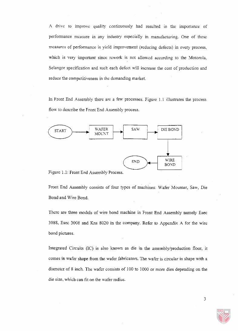
In Front End Assembly there are a few processes. Figure 1.1 illustrates the process
flow to describe the Front End Assembly process.
(zJ+pq BOND
Figure 1.1 : Front End Assembly Process.
Front End Assembly consists of four types of machines: Wafer Mounter, Saw, Die
Bond and Wire Bond.
SAW *
There are three models of wire bond machine in Front End Assembly namely Esec
3088, Esec 3008 and Kns 8020 in the company. Refer to Appendix A for the wire
bond pictures.
DIE BOND
L---J
WAFER MOUhT
Integrated Circuits (IC) is also known as die in the assembly/production floor, it
comes in wafer shape from the wafer fabricators. The wafer is circular in shape with a
diameter of 8 inch. The wafer consists of 100 to 1000 or more dies depending on the
die size, which can fit on the wafer radius.
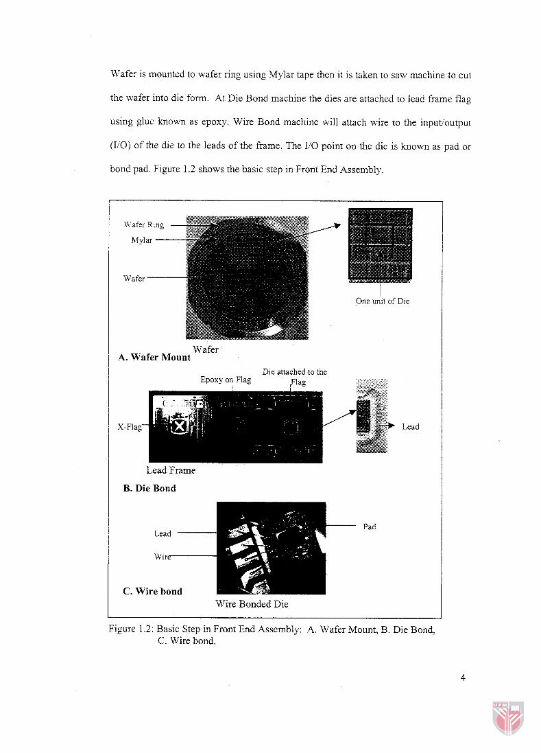
Wafer is mounted to wafer ring using Mylar tape then it is taken to saw machine to cut
the wafer into die form. At Die Bond machine the dies are attached to lead frame flag
using glue known as epoxy. Wire Bond machine will attach wire to the inputioutput
(IiO) of the die to the leads of the frame. The 110 point on the die is known as pad or
bond pad. Figure 1.2 shows the basic step in Front End Assembly.
Wafer
One u i i t of Die
Wafer A. Wafer Mount
Die attached to the Epoxy on Flag
I
Lead Frame
B. Die Bond
C. Wire bond Wire Bonded Die
Figure 1.2: Basic Step in Front End Assembly: A. Wafer Mount, B. Die Bond, C. Wire bond.
Introduction to Wire Bonding
Wire Bonding is a critical stage in the assembly process. By this stage, most of the
device costs have been absorbed; therefore, the success of the remaining processes is
critical. Precision and quality of performance are imperative at this stage to assure
high yields.
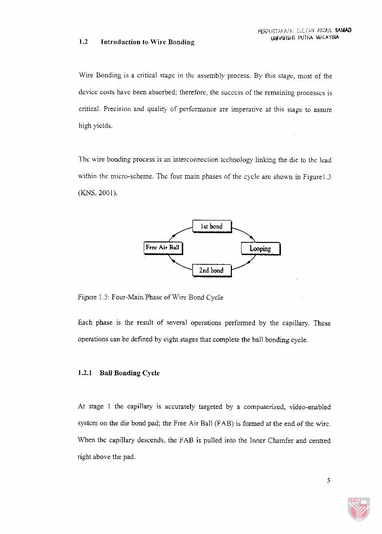
The wire bonding process is an interconnection technology linking the die to the lead
within the micro-scheme. The four main phases of the cycle are shown in Figurel.3
(KNS, 2001).
1 st bond A 2nd bond
Figure 1.3: Four-Main Phase of Wire Bond Cycle
Each phase is the result of several operations performed by the capillary. These
operations can be defined by eight stages that complete the ball bonding cycle.
1.2.1 Ball Bonding Cycle
At stage 1 the capillary is accurately targeted by a computerized, video-enabled
system on the die bond pad; the Free Air Ball (FAB) is formed at the end of the wire.
When the capillary descends, the FAB is pulled into the Inner Chamfer and centred
right above the pad.
At stage 2 the 1st bond is created when the FAB is squashed by the capillary against
the pad. During this process, the FAB is gripped in the capillary chamfer while force
and ultrasonic vibrations are transmitted through the capillary and heat is applied
throughout.
At stage 3 when the 1st bond is formatted, the capillary rises above the pad. The
opening of the clamp allows the wire to slide through and reach the desired loop
height. At this point the clamp closes again.
At stage 4 while the clamp is closed, the capillary moves towards the lead and is
lowered to form the 2nd bond. This lowering motion forms the loop.
At stage 5 the capillary presses the wire against the lead while force, heat, and
ultrasonic eneru are applied. This pressure produces the 2nd bond, which consists of
the stitch bond and the tail bond.
At this stage 6 the clamp opens while the capillary rises from the lead to a carefully
defined point. The strength of the tail bond is a critical factor for the success of the
entire cycle. A proper tail bond assists in avoiding such phenomena as "EFO open"
and "short tail". The tail bond needs to remain attached to the lead until the capillary
reaches the desired height.
At stage 7 the capillary rises above the lead. At the desired height, as the capillary
continues its upward ascent, the clamp closes and the tail bond is detached from the
lead while the stitch bond remains attached.
At stage 8 the tail bond is now positioned above the pad. The end of the tail melts as
the result of an electrical spark originated by the Electronic Flame Off (EFO) wand.
The surface tension of the melted gold causes the drop to acquire the shape of a nearly
perfect sphere, thus, creating the FAB. When the FAB solidifies, the cycle begins
anew.
Figure 1.4 shows the stages in the bonding cycle (KNS: 200 1).