Embed Size (px)
Citation preview
UNIVERSITI PUTRA MALAYSIA
DEVELOPMENT OF CAD/CAM SYSTEM FOR COLD WORKING CLOSED DIE FORGING PROCESS
MOHAMED A. ABDULMAWLLA
FK 2000 11
DEVELOPMENT OF CAD/CAM SYSTEM FOR COLD WORKING CLOSED DIE FORGING PROCESS
By
MOHAMED A. ABDULMA WLLA
Thesis Submitted in Fulfilment of Requirements for the Degree of Master of Science in the Faculty of Engineering
U niversiti Putra Malaysia
June 2000

11
DEDICATED TO
MY PARENTS
Abstract of thesis presented to the Senate of Universiti Putra Malaysia in fulfilment of the requirements for the degree of Master of Science.
DEVELOPMENT OF CAD/CAM SYSTEM FOR CLOSE DIE FORGING PROCESS
By
MOHAMED A. ABDULMA WLLA
June 2000
Chairman: A. M. S. Ramouda, Ph D.
Faculty: Engineering
iii
The application of computer-aided engineering (CAE), design (CAD), and
manufacturing (CAM), is essential in modern metal forming technology. Thus,
process of modelling for the investigation and understanding of deformation
mechanics has become a major concern in recent and advanced research, and the
finite element method (FEM.) has assumed increased importance, particularly in the
modelling of deformation processes.
This work is devoted to the development of CAD/CAM system for closed die
forging process. The system development consists of three stages: namely, metal
flow simulation, die failure analysis and design optimisation, and development and
implementation of machining code. In the first stage, the finite element method was
used to simulate the axisymmetric closed die forging process of copper material. The
method was used to study the metal flow, die filling retaining the non-linearity
involved in the large change in the geometry, the continuous change in the contact
surface condition and the isotropic material work-hardening characteristics. In the
second stage, a finite element analysis and optimisation algorithm was developed to
IV
examine the die fatigue life and to optimise the die design. The finite element
analysis in the first and second stage was carried out using commercially available
finite element software called LUSAS. In the third stage, a machining code for the
optimised die was developed and implemented using CAD/CAM software called
UniGraphics and CNC machine. A qualitative comparison between the
computational results and experiments ware made.
It had been found that the early stage of the metal flow in closed die forging
was very similar to a simple upsetting, then the material flows into the die cavity and
towards the flash land leading to a very sharp increase in forging load. The die was
designed to sustain the forging load and withstand 1000 load cycles.
v
PEHYL..; !Ah.:\V� JNIVi:R.SJTJ PllTH.., , ,
Abstrak tesis yang dikemukakan kepada Senat UiuverslTIPUffa Malay��\' SlA sebagai memenuhi keperluan untuk ijazah Master Sains,
PEMBANGUNAN SISTEM CAD/CAM BAGI PROSES ACUAN TEMPAAN TERTUTUP
Oleh
MOHAMED A. ABDULMA WLLA
June 2000
Pengerusi: A.M.S. Hamouda, Ph.D.
Fakulti: Kejuruteraan
Aplikasi kejuruteraan terbantu komputer (CAE), reka bentuk terbantu
komputer (CAD) dan pembuatan terbantu komputer (CAM) adalah penting dalam
teknologi pembentukan logam moden. Jadi, pemodelan proses bagi kajian dan
pemahaman mekanik ubah bentuk telah menjadi satu tumpuan utama dalam
penyelidikan terkini dan maju, dan kaedah unsur terhingga (FEM) telah menjadi
begitu penting, terutamanya dalam pemodelan proses ubah bentuk.
Penyelidikan ini ditumpukan kepada pembangunan sistem CAD/CAM bagi
proses tempaan acuan tertutup. Pembangunan sistem terdiri dari 3 tahap: iaitu
penyelakuan aliran logam, analisis kegagalan acuan dan pengoptimuman reka
bentuk, dan pembangunan dan pelaksanaan kod pemesinan. Dalam tahap pertama,
kaedah unsur terhingga telah digunakan untuk menyelaku proses tempaan acuan
tertutup paksi simetri bagi bahan tembaga. Kaedah ini telah digunakan untuk
mengkaj i aliran logam, pengisian acuan dengan mengekalkan ketaklelurusan yang
terlibat dalam perubahan besar geometri, perubahan berterusan dalam keadaan
permukaan sentuhan dan ciri-ciri pengerasan kerja bahan isotropi. Dalam tahap
vi
kedua, satu analisis unsur terhingga dan algorithma pengoptimuman telah
dibangunkan untuk memeriksa hay at lesu acuan dan mengoptimum reka bentuk
acuan. Analisis unsur terhingga dalam tahap pertama dan kedua telah dilaksanakan
menggunakan peri sian unsur terhingga yang wujud secara komersial yang dipanggil
LUSAS. Dalam tahap ketiga, kod pemesinan bagi acuan teroptimum telah
dibangunkan dan dilaksanakan menggunakan peri sian CAD/CAM yang dipanggil
UniGraphics dan mesin CNC. Satu perbandingan kualitatif di antara keputusan
perkomputeran dan ujikaji telah dilakukan.
Telah dapat diperhatikan bahwa pengaliran logam diperingkat awal
penempaan acuan tertutup adalah bersamaan dengan tempa-dempak mudah. Bahan
kemudiannya mengalir ke rongga acuan menuju ke flash-land. Fonomema ini
mengakibatkan beban tempaan meningkat dengan mendadak.Acuan tersebut telah
direkabentuk agar mampu menerima beban tempaan dengan selamat dan dapat
menahan beban sehingga 1000 kitaran.
VB
ACKNOWLEDGEMENTS
First of all, I would hke to express my greatest thanks and gratitude to Allah
(S W T ) the most gracious and merciful for giving me the ability to carry out this
work
I would like to express my great respect and gratitude to the chairman of the
supervisory committee, Dr A M S Hamouda, for his support, excellent
supervision, guidance and constructIve suggestion and valuable comments through
the duration of the project
I would like also to thank the members of the supervisory committee, Assoc
Prof Dr Shamsuddin bin Suialman and Dr Megat M Hamdan, Head of
Manufacturing and Mechamcal Engineering Department for their guidance and
assistance during the period of this work
Appreciation also to the assistance rendered by the respective lecturers,
technicians and staff of the facuIty of engineering for providing the facilities required
for undertaking this project
I am grateful to my beloved country LIbya and the Engineering Academy,
Tajoura for offering me the scholarship for pursuing the Master degree at Universiti
Putra Malaysia SpeCIal thanks go to all the lovely members of my family and
relatives without their encouragement and overwhelming support this work would
not have been possible
V1l1
I certify that an Examination Committee met on 19th June 2000 to conduct the final examination of Mohamed A Abdulmawlla on his Master of Science thesis entitled "Development of CAD/CAM System for Closed Die Forging Process" in accordance with Universiti Pertanian Malaysia (Higher Degree) Act 1980 and Universiti Pertanian Malaysia (Higher Degree) Regulations 198 1 The Committee recommends that the candidate be awarded the relevant degree Members of the Examination Committee are as follows
Md Yusof Ismail, Ph.D Faculty of Engineering Universiti Putra Malaysia (Chairman)
A M. S Hamouda, Ph.D Faculty of Engineering Universiti Putra Malaysia (Member)
Shamsuddin bin Sulaiman, Ph D Faculty of Engineering Universiti Putra Malaysia (Member)
Megat M. Hamdan, Ph D Faculty of Engineering Universiti Putra Malaysia (Member)
GHAZALI MOHA YIDIN, Ph.D, ProfessorlDeputy Dean of Graduate School, Universiti Putra Malaysia
Date 2 7 JUN 2000

IX
This thesis submitted to the Senate of Universiti Putra Malaysia and was accepted as fulfilment of the requirements for the degree of Master of Science.
KAMIS A WANG, Ph.D, Associate Professor Dean of Graduate School, Universiti Putra Malaysia
Date: 1 3 JUL 2000

DECLARATION FORM
I hereby declare that the thesis is based on my original work except for quotations and citations, which have been duly acknowledged. I also declare that it has not been previously or concurrently submitted for any other degree at UPM or other institutions.
Signed
Name: Mohamed A. Abdulmawlla Date: 26 June 2000
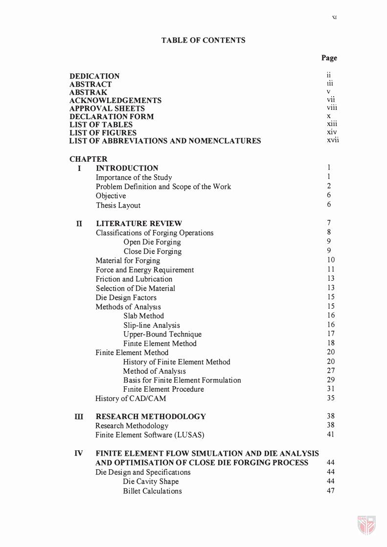
TABLE OF CONTENTS
DEDICATION ABSTRACT ABSTRAK ACKNOWLEDGEMENTS APPROVAL SHEETS DECLARATION FORM LIST OF TABLES LIST OF FIGURES LIST OF ABBREVIATIONS AND NOMENCLATURES
CHAPTER I INTRODUCTION
Importance of the Study Problem Definition and Scope of the Work Objective Thesis Layout
II LITERATURE REVIEW Classifications of Forging Operations
Open Die Forging Close Die Forging
Material for Forging Force and Energy Requirement Friction and Lubrication Selection of Die Material Die Design Factors Methods of AnalysIs
S lab Method Slip-line Analysis Upper-Bound Technique Fimte Element Method
Finite Element Method History of Finite Element Method Method of AnalysIs Basis for Finite Element Formulation Fmite Element Procedure
History of CAD/CAM
ill RESEARCH METHODOLOGY Research Methodology Finite Element Software (LUSAS)
IV FINITE ELEMENT FLOW SIMULATION AND DIE ANALYSIS
Page
11 111 V VB Vlll X Xlll XIV XVll
1 1 2 6 6
7 8 9 9 1 0 1 1 1 3 1 3 1 5 1 5 1 6 1 6 1 7 1 8 20 20 27 29 3 1 35
3 8 38 41
AND OPTIMISATION OF CLOSE DIE FORGING PROCESS 44 Die Design and Specifications
Die Cavity Shape Billet Calculations
44 44 47
V
VI
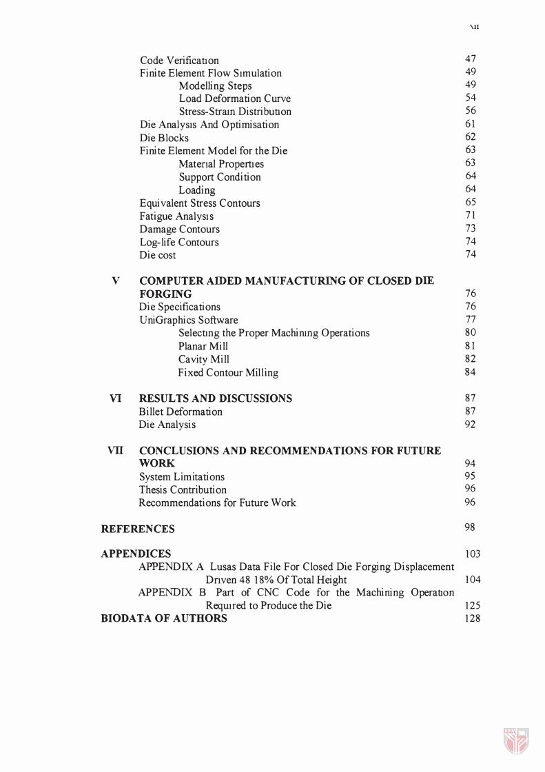
Code VerificatIon Finite Element Flow S Imulation
Modelling Steps Load Deformation Curve Stress-Stram Distribution
Die AnalysIs And Optimisation Die Blocks Finite Element Model for the Die
Matenal PropertIes Support Condition Loading
Equivalent S tress Contours Fatigue AnalysIs Damage Contours Log-life Contours Die cost
COMPUTER AIDED MANUFACTURING OF CLOSED DIE FORGING Die Specifications UniGraphics Software
Selectmg the Proper Machinmg Operations Planar Mill Cavity Mill Fixed Contour Mil l ing
RESUL TS AND DISCUSSIONS Billet Deformation Die Analysis
'.11
47 49 49 54 56 61 62 63 63 64 64 65 71 73 74 74
76 76 77 80 81 82 84
87 87 92
VII CONCLUSIONS AND RECOMMENDATIONS FOR FUTURE WORK 94 System Limitations 95 Thesis Contribution 96 Recommendations for Future Work 96
REFERENCES 98
APPENDICES 103 APPENDIX A Lusas Data File For Closed Die Forging Displacement
Dnven 48 18% Of Total Height 104 APPENDIX B Part of CNC Code for the Machining OperatIOn
ReqUIred to Produce the Die 125 BIODATA OF AUTHORS 128

LIST OF TABLES
TAB LE
1 Metal forming system
2 Ratio of endurance limit to tensIle strength
'Ull
Page
4
72
Xl\
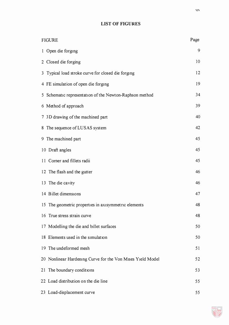
LIST OF FIGURES
FIGURE Page
1 Open die forgIng 9
2 Closed die forging 10
3 Typical load stroke curve for closed die forgIng 1 2
4 FE simulation of open die forgIng 1 9
5 SchematIc representatIon of the Newton-Raphson method 34
6 Method of approach 39
7 3D drawing of the machined part 40
8 The sequence ofLUSAS system 42
9 The machined part 45
1 0 Draft angles 45
1 1 Corner and fillets radii 45
1 2 The flash and the gutter 46
1 3 The die cavity 46
14 Billet dimenslOns 47
15 The geometric propertIes in aXIsymmetnc elements 48
1 6 True stress strain curve 48
1 7 Modelling the die and bIllet surfaces 50
1 8 Elements used in the simulatlOn 50
1 9 The undeformed mesh 51
20 Nonlinear Hardemng Curve for the Von Mlses YIeld Model 52
2 1 The boundary conditlOns 53
22 Load distribution on the die line 55
23 Load-displacement curve 55
24 Mesh dIstortIOn at dIfferent stages 56
25 Displacement vectors at different stages 57
26 Stress contours at dIfferent stages 59
27 Strain distribution at different stages 60
28 Deformed and undeformed mesh 65
29 Stresses and displacement distnbutions for 40mm die 68
3 0 Stresses and displacement distnbutions for 60mmdie 69
3 1 Stresses and displacement distnbutions for 80mm die 7 1
3 2 Typical S -N curve for steel 72
33 Contour of damage 73
34 Log-life contour 74
3 5 Mechanical drawing of the die 75
36 2D drawing of optimIsed dIe 77
3 7 Operational sequence 78
3 8 The operation manager 79
3 9 Machining operatIOns 8 1
40 Tool paths for planar mIll ing operatIon 82
4 1 Parts where Planar and CavIty Mill are useful 83
42 Tool paths for first cavIty millmg operatlOn 83
43 Tool paths for the second cavIty mtlling operation 84
44 Fixed contour tool diameter and comer radius 85
45 Isometric view of the tool path m fixed contour operation 85
46 Front view of the tool path m fixed contour operation 86
47 Deformed mesh 20% reduction 88
48 Deformed mesh 40% reductlOn 88

'\'VI
49 Deformed mesh just before the final stage 89
50 Deformed mesh final stage 89
51 Effective stress distnbution at 30% reduction 90
52 Effective stress distribution In final stage 91
53 Strain distribution at the final stage 91
54 Effective stress distributIon in the die and the billet at final stage 93
XVll
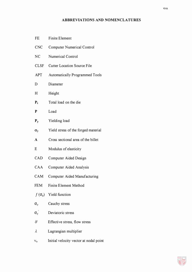
ABBREVIA TIONS AND NOMENCLATURES
FE Finite Element
CNC Computer Numerical Control
NC Numerical Control
CLSF Cutter Location Source File
APT Automatically Programmed Tools
D Diameter
H Height
Pt Total load on the die
P Load
Py Yielding load
O'y Yield stress of the forged material
A Cross sectional area of the billet
E Modulus of elasticity
CAD Computer Aided Design
CAA Computer Aided Analysis
CAM Computer Aided Manufacturing
FEM Finite Element Method
f (al;) Yield function
all Cauchy stress
all Deviatoric stress
CY Effective stress, flow stress
A Lagrangian multiplier
vo Initial velocity vector at nodal point
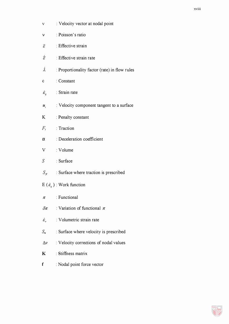
v : Velocity vector at nodal point
v : Poisson's ratio
8 : Effective strain
8 : Effective strain rate
i : Proportionality factor (rate) in flow rules
c : Constant
BI] : Strain rate
UI : Velocity component tangent to a surface
K : Penalty constant
F/ : Traction
ex : Deceleration coefficient
V : Volume
S : Surface
SF : Surface where traction is prescribed
E ( BI] ) : Work function
1C : Functional
01C : Variation of functional 1C
Bv : Volumetric strain rate
Su : Surface where velocity is prescribed
�v : Velocity corrections of nodal values
K : Stiffness matrix
f : Nodal point force vector
xviii
CHAPTER I
INTRODUCTION
In this chapter, the undertaking of the work is justified, identify the aims of
the study and outline the method of approach adopted to achieve the set objectives.
Finally, a summary of the content of different chapters is provided under the heading
" Layout of thesis" .
Importance of the Study
In manufacturing operations many parts are fonned into various shapes by
applying external forces to the workpiece by means of tools and dies. Typical
operations are forging, extrusion and rolling. Because defonnation in these processes
is carried out by mechanical means, an understanding of the behaviour of the
materials in response to applied forces is important. In addition, the behaviour of
manufactured part during its expected service life is an important consideration.
Unlike rolling operation, which generally produce continuous plates, sheets,
and strips, forging operation produce wide variety of discrete parts. Metal flow and
the grain structure can be controlled, so forged parts have good strength and
toughness. Thus they can be used reliably for highly stressed and critical
applications. Die design material behaviour during deformation, as well as friction,
and material flow characteristics in a die cavity, are important in design
2
consideration. Also important is the proper selection of die-materials, temperature,
speed, lubricant and equipment.
Recently, computer-aided design and manufacturing are being implemented
increasingly in all aspects of forging design and manufacturing. Techniques being
used include modelling of the deformation of the workpiece and finite element
analysis during forging in the dies, die design, calculation of forces, and prediction of
die failure.
Problem Definition and Scope of the Work
The ultimate goal of manufacturing engineer is to produce component of
selected material with a required geometrical shape and a structure optimised for the
proposed service environment. In general, forging processes tend to be complex
system of independent variables, dependent variables and independent-dependent
interrelations. Independent variables are those aspects of the process over which the
engineer has a direct control and are generally selected or set up when setting up the
process. Among the typical independent variables considered are: -
• S tarting material. The engmeer must specify the chemistry and the
condition of the material to be machined.
• Starting workpiece geometry. This may be dictated by previous
processing or may be selected by the engineer from a variety of available
shapes, often on basis of economics.
3
• Tool or die geometry It has many aspects such as the die material, die
angles and cavity details, which have wide variety and so different effect
on the process
• Amount of deformation. The amount of deformation is limited by the
material properties and its ability to deform It should be taken in
consideration during die design according to the shape of the workpiece
material
After the manufacturing engmeer specifies the independent variables, the
process then determines the nature and values for a second set of variables, known as
dependent variables Examples include -
• Force and power requirements. To deform a given material from a given
starting shape to a specified final shape, with a specified friction
coefficient, speed and starting temperature, will require a certain amount
of force or power A change in any of the independent variables will bring
about a change in the force or power required
• Material properties of the product While the engineer can specify the
properties of the starting material, the combined deformation and
temperature changes imparted by the process will certainly modify them.
The customer is not interested in the starting properties, but rather the
final properties of the product. Thus, while it is often desirable to select
starting properties based on compatibility with the process, it is also
necessary to know or be able to predict how the process will alter them.
4
• Surface finIsh and precision. Both are product characteristic and depends
on the specific details of the process.
• Nature of material flow Deformation process exerts external constrains
on the material through control and movement of its surfaces. S ince
properties depend on the deformation history, control here is vital
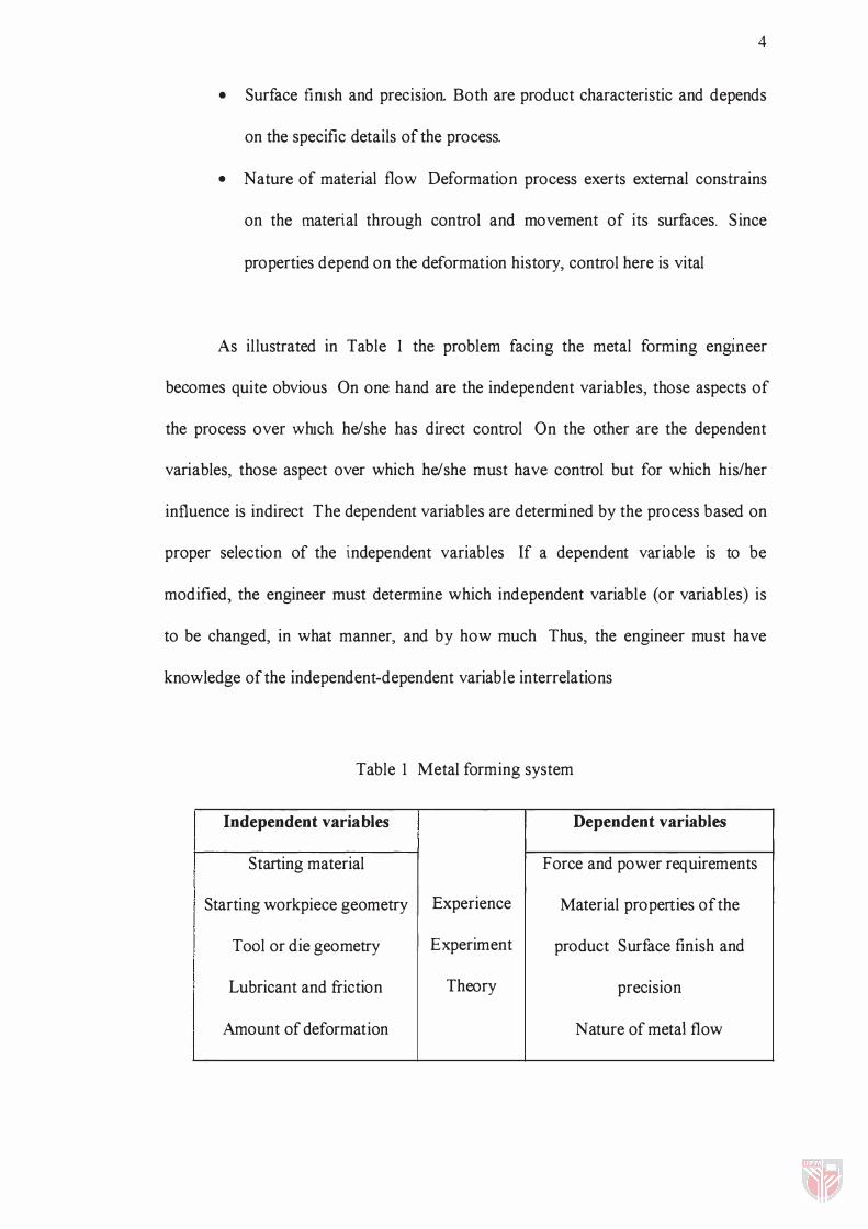
As il lustrated in Table 1 the problem facing the metal forming engmeer
becomes quite obvious On one hand are the independent variables, those aspects of
the process over WhICh he/she has direct control On the other are the dependent
variables, those aspect over which he/she must have control but for which his/her
influence is indirect The dependent variables are determined by the process based on
proper selection of the independent variables If a dependent variable is to be
modified, the engineer must determine which independent variable (or variables) is
to be changed, in what manner, and by how much Thus, the engineer must have
knowledge of the independent-dependent variable interrelations
Table 1 Metal forming system
Independent variables Dependent variables
Starting material Force and power requirements
Starting workpiece geometry Experience Material properties of the
Tool or die geometry Experiment product Surface finish and
Lubricant and friction Theory . .
preCISIon
Amount of deformation Nature of metal flow
5
PERPUSTAKAAl\I The link between the independent and de���l-IamN �lA
important area of knowledge for the manufacturing engineer Unfortunately, such
l inks are often difficult to obtain Metal forming process is a complex system
composed of the material being deformed, the tool performing the deformation and
various other process parameters Also various materials often behave differently
The ability to predict and control dependent variables, therefore, comes about
in one of three ways -
1 Experience This reqUIres long-time exposure to the process and IS often
restricted in scope by the realm of past contact
2 Experiment While possibly the least likely to be in error, direct experiment is
both costly and time consuming
3 Modelling. Here one attempt to develop a mathematical model of the process
into which numerical values for the various independent variables can be
inserted and compute a prediction for the dependent variables. Most
techniques rely on the applied theory of plasticity with two-dimensional
stresses. Alternatives vary from first-order approximations, such as slab
equil ibrium or uniform deformation energy calculation, to sophisticated,
computer-based, solution, such as the finite element or finite difference
methods
6
Objective
The present work focuses on simulating non-steady forging process using a
finite element techmque III order to come up with a clear and better understanding of
metal flow and stress distribution in the process It is also to study the effect of
independent and dependent variables on the die So the aims of this work are -
• To develop a finite element algorithm to model forging process
• To conduct finite element analysis and optimisation on the die life
• To develop a CNC code for the manufacturing of the die
Thesis Layout
The thesis is organised into seven chapters The first chapter gives an
introduction to the research and its objectives The second chapter contains an up to
date literature review metal forming history, basic aspects of forging and some
important terms and definitions The third chapter contains a brief and general
overview about this work and the finite element software used in analysing the
forging process The fourth chapter contains application of FEA to non-steady state
closed die forging process, die optimisation and die fatigue analysis using LUSAS
software The fifth chapter contains die modelling using CAD/CAM software and
generating the machining code for die manufacturing The sixth chapter contains the
results and discussion The final chapter contains conclusion and suggestions for
future work


![PENYELAKUAN REKA BENTUK ANTENA TAMPAL SEGI TIGA …eprints.utm.my/id/eprint/1431/1/JT37D[7].pdfteori disebabkan keterbatasan perisian pada ingatan 16 Mbyte. Kedudukan suapan yang sepadan](https://img.pdfslide.net/doc/110x75/5e37a1a31762590a003eef45/penyelakuan-reka-bentuk-antena-tampal-segi-tiga-7pdf-teori-disebabkan-keterbatasan.jpg)