Embed Size (px)
Citation preview
UNIVERSITI PUTRA MALAYSIA
DEVELOPMENT OF TERRAIN ANALYSIS DATABASE USING MILITARY GEOGRAPHIC INFORMATION
SYSTEM
MOHD ZAMBRI BIN MOHAMAD RABAB
FH 2002 18
DE VELOPME NT OF TERRAIN ANALY SIS DATABASE USING MILITARY GE OGRAPHIC INFORMATION SY STE M
By
MOHD ZAMBRI BIN MOHAMAD RABAB
Thesis Submitted to the School of Graduate Studies, Universiti Putra Malaysia, In Fulfillment of the Requirements for the Degree of Doctor of Philosophy
August 2002
Abstract of thesis presented to the Senate of the Universiti Putra Malaysia in fulfillment of the requirement for the degree of Doctor of Philosophy
DEVELOPMENT OF TE RRAIN ANALY SIS DATABASE USING MILITARY GE OGRAPHIC INFORMATION SY STE M
By
MAJ OR MOHD ZAMBRI BIN MOHAMAD RABAB
August 2002
Chairman: Maj or Prof Dr Kamaruzaman Jusoff
Faculty: Forestry
The Information and Communication Technology (lCT) that includes
military geospatial information will play a key role in the Revolution of Military
Affair (RMA) for future warfare. The Terrain Analysis (TA) database is one of the
military geospatial information that needs to be established in the Malaysian Armed
Forces (MAF) in order to enable various Military Geographic Information System
(MGIS) to perform analyses and produce Tactical Decision Aids (TDA) products.
This study focused on the establishment of T A database structure that
consisted of several layers namely Surface Configuration - Slope, Vegetation,
Surface Material - Soils, Surface Drainage, Transportation and Obstacle Layers. A
prototype T A database was established in order to evaluate the effectiveness of the
database in generating Cross Country Movement (CCM) map. Results revealed that
the topographic data from Department of Survey and Mapping Malaysia in
Topologiz ed Topographic Mapping (TTM) database, soil data from Department of
11
Agriculture and the analyses of IKONOS imagery and ground data collection using
GPS Geo Explorer 3 have contributed significantly to the development of prototype
TA database. GIS technology was thoroughly utiliz ed in implementing a user
interface menu and CCM map from prototype T A database. Results showed that GIS
technology has provided a powerful tool in successfully generating both products.
The results of this study have contributed significantly to the science and art
of military aspect of terrain. Most of the MAF projects especially the Command,
Control, Communication and Intelligence (C3I) system that use MGIS will benefit
from the TA database structure for producing and analyz ing various TDAs products.
This study has produced the first TA database for the country and hopefully to be
used by the Royal Engineer (RE) Corps. The structure of T A database will be
proposed to higher level military council in order to officially implement in MAF.
Future study shall focus on the automatic rapid extraction of T A feature and
attribute from hyperspectral, airborne Interferometric Synthetic Aperture Radar
(IFSAR) and Light Detection and Ranging (LIDAR) imageries. Such study should
also focus on validating soil data from the Department of Agriculture in accordance
with military engineering specification. Implementing open and shared database
concept for military geospatial inf ormation is also an important research that is
required. The development of CCM products using NRMM II model and the
enhancement of user interface menu for TA database should be further investigated
and implemented.
III
Abstrak tesis yang dikemukakan kepada Senat Universiti Putra Malaysia sebagai memenuhi keperluan untuk Ijazah Doktor Falsafah
PE MBANGUNAN PANGKALAN DATA ANALISA MUKA BUMI MENGGUNAKAN SISTE M MAKLUMAT
GE OGRAFI KETENTERAAN
Oleh
MEJAR MOHD ZAMBRI BIN MOHAMAD RABAB
Ogos 2002
Pengerusi: Mej ar Prof Dr Kamaruzaman Jusoff
Fakulti: Perhutanan
Maklumat geospatial pertahanan yang merupakan sebahagian daripada
Teknologi Maklumat dan Komunikasi akan memainkan peranan utama di dalam
Revolusi Hal Ehwal Tentera bagi peperangan mas a hadapan. Mak lumat data Analisa
Muka Bumi (AMB) adalah salah satu daripada maklumat geospatial pertahanan yang
perlu diwujudkan dalam Angkatan Tentera Malaysia (ATM) untuk membolehkan
pelbagai Sistem Maklumat Geografi (SMG) ketenteraan melaksanakan analisis dan
menghasilkan produk-produk Bantuan Keputusan Taktikal (BKT) bagi merancang
operasi ketenteraan.
Fokus kaji selidik ini adalah kepada pembangunan struktur pangkalan data
AMB yang mengandugi lapisan-lapisan seperti Kecerunan, Tumbuh-Tumbuhan,
Tanah , Saliran, Pengangkutan dan Halangan. Pangkalan data prototaip AMB telah
dibangunkan bagi menilai keberkesanannya dalam menghasilkan peta Cross Country
IV
Movement (CCM). Keputusan kajian telah menunjukkan bahawa data pemetaan
topografi berdigit daripada Jabatan Ukur dan Pemetaan Malaysia (JUPEM) dalam
format Pemetaan Topografi Bertopologi (PTB), data tanah daripada Jabatan
Pertanian Malaysia dan hasil analisis imej satelit IKONOS serta pengumpulan data di
lapangan menggunakan peralatan GPS Geo Explorer 3 telah dapat menyumbang
kepada pembangunan pangkalan data prototaip AMB. Teknologi SMG telah
digunakan sepenuhnya dalam membangunkan menu paramuka untuk pengguna dan
peta CCM daripada pangkalan data prototaip AMB tersebut. Teknologi SMG telah
digunakan dengan jayanya untuk menyediakan dan menjanakan kedua-dua produk
tersebut.
Hasil kajian selidik ini telah dapat menyumbangkan kepada seni dan sains
terhadap aspek muka bumi tujuan ketenteraan. Sistem-sistem canggih A TM seperti
projek Pemerintahan, Pengawalan, Perhubungan dan Perisikan (P4) yang berasaskan
SMG akan mendapat manfaat daripada struktur pangkalan data AMB tersebut untuk
mengeluarkan pelbagai produk BKT. Kajian ini telah menghasilkan struktur
pangkalan data AMB yang pertama untuk negara Malaysia dan berharap ianya akan
digunakan oleh Kor Askar Jurutera DiRaja. Struktur pangkalan data AMB yang
dibangunkan akan diketengahkan untuk kelulusan majlis tertinggi A TM supaya ianya
dapat dilaksanakan di ATM.
Kajian akan datang perlu difokuskan kepada penawanan pantas secara
automatik terhadap butiran dan atribut AMB daripada imageri yang diperolehi
melalui konsep hyperspectra/, airborne Interferometric Synthetic Aperture Radar
(lFSAR) and Light Detection and Ranging (UDAR) . Kajian juga harus ditumpukan
kepada pengesahan data tanah yang diperolehi daripada Jabatan Pertanian Malaysia
menurut spesifikasi dan piawaian kejuruteraan tentera. Perlaksanaan konsep
v

pangkalan data terbuka untuk maklumat geospatial pertahanan supaya dapat dikongsi
oleh semua pengguna aplikasi SMG haruslah dikaji kesesuaiannya di dalam ATM.
Penjanaan produk CCM menggunakan model NRMM II serta peningkatan untuk
mencanggihkan menu paramuka pengguna bagi memanipulasi pangkalan data AMB
perlu dibuat kajian yang lebih mendalam.
VI

ACKNOWLE DGE ME NTS
First and foremost, I would like to express my heart-felt gratitude to my
major supervisor, Maj Prof Dr Kamaruzaman Jusoff for his guidance,
encouragement, support and friendship. I thank him for his input in this study, for his
patience and for the knowledge I gained from his comments and suggestions. I would
like to thank my supervisory committee members, Assoc Prof Dr Azizi Hj Muda and
Dr Anuar Abdul Rahim for their constructive criticism that substantially improve this
study. I would also like to extend my appreciation to Field Research Assistants, Pak
Lah, Hasif, Ashwan and Pak Mat, who have provided full commitment in assisting
the collection of ground data and ground verification analysis over the study area.
I would like to acknowledge Brig Gen Dato' Pahlawan Mohamad Tairobi
Abdul Razak, the Chief Engineer of Royal Engineer Corps for his blessing and
continuous encouragement in completing this study. Special appreciation also goes to
Col Jamil Tahir, the Director of Defence Mapping for his continuous support,
patience, diligence and invaluable help. I thank him for allowing me to continue with
the study while at the same time working as a full time military officer. I would also
like to extend my appreciation to Brig Gen (Retired) Dato' Abdul Rahman Ismail the
former Director of Defence Mapping for his first blessing in pursuing with this study.
Special appreciation also goes to the Department of Survey and Mapping
Malaysia, Department of Agriculture Malaysia and Department of Forestry
Peninsular Malaysia for providing useful data that contributed to the success of the
study. I am sincerely thankful for their assistance to overcome inherent weakness in
understanding their data structure.
Vll

Finally, all I have accomplished would not have been possible without the
consistent support of my family. To my parent Mohamad Rabab Yaakob and Siti
Mariam Ahmad, wife Maj Dr Liana Ma Abdullah and son Muhammad Danish
Aiman who not only endured without protest the loneliness while I prepared my
dissertation, but also provided their loving encouragement throughout this long
study.
Vlll
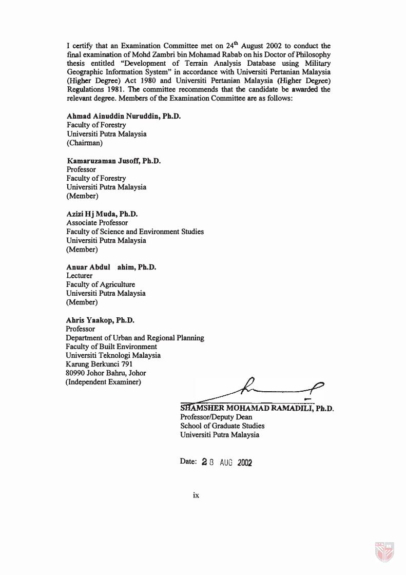
I certify that an Examination Committee met on 24th August 2002 to conduct the final examination of Mohd Zambri bin Mohamad Rabab on his Doctor of Philosophy thesis entitled "Development of Terrain Analysis Database using Military Geographic Infonnation System" in accordance with Universiti Pertanian Malaysia (Higher Degree) Act 1980 and Universiti Pertanian Malaysia (Higher Degree) Regulations 1981. The committee recommends that the candidate be awarded the relevant degree. Members of the Examination Committee are as follows:
Ahmad Ainuddin Nuruddin, Ph.D. Faculty of Forestry Universiti Putra Malaysia (Chainnan)
Kamaruzaman Jusoff, Ph.D. Professor Faculty of Forestry Universiti Putra Malaysia (Member)
Azizi Hj Muda, Ph.D. Associate Professor Faculty of Science and Environment Studies Universiti Putra Malaysia (Member)
Anuar Abdul Rahim, Ph.D. Lecturer Faculty of Agriculture Universiti Putra Malaysia (Member)
Ahris Yaakop, Ph.D. Professor Department of Urban and Regional Planning Faculty of Built Environment Universiti Teknologi Malaysia Karung Berkunci 791 80990 lohor Bahru, lohor (Independent Examiner)
�--:f' SlIAMSHER MOHAMAD RAMADILI, Ph.D. ProfessorlDeputy Dean School of Graduate Studies Universiti Putra Malaysia
Date: 2 8 AUG 2002
ix
This thesis submitted to the Senate of Universiti Putra Malaysia and was accepted as fulfillment of the requirement for the degree of Doctor of Philosophy_ The members of the Supervisory Committee are as follows:
Kamaruzaman Jusoff, Ph.D. Professor Faculty of Forestry Universiti Putra Malaysia (Chairman)
Azizi Hj Muda, Ph. D. Associate Professor Faculty of Science and Environment Studies Universiti Putra Malaysia (Member)
Anuar Abdul Rahim, Ph.D. Lecturer Faculty of Agriculture Universiti Putra Malaysia (Member)
x
AINI IDERIS, Ph. D. ProfessorlDean School of Graduate Studies Universiti Putra Malaysia
Date:
DECLARATION
I hereby declare that the thesis is based on my original work except for quotations and citations which have been duly acknowledged. I also declare that it has not been previously or concurrently submitted for any other degree at UPM or other
institutions.
HD ZAMBRI MOHAMAD RABAB)
Date: 26 August 2002
Xl
TABLE OF CONTENTS
ABSTRACT . ....... .................. ....... ................ .... . .. . ................... . .. .... ii ABSTRAK ............ ... . . . .. . ... ............. ....... . ... .. . .............. ....... . ... ........ iv ACKNOWLEDGEMENTS ................ ... .... .................... . . . ................. vii APPROVAL SHEETS . ................ . .......... ... .......... ... . ... . .. .... ... ............ ix DECLARATION FORM ......... .. .............. ... .......... . ................... . . . . . .... xi LIST OF FIGURES ... .. . .. . ... ...... ................. ... . ... .... ... .... .................... xv LIST 0 F TABLES ............. ... ... . .. ........ ............. .. ... . . . ...... ................. xix LIST OF ABBREVIATIONS . ... ......... ....... ...... ..... ... ... ......................... xx
CHAPTER
1 INTRODUCTION .................................................................................... � .......... 1 .1 1 . 1 General . . . . . . . .. . . . . . .. .............................. ..... .. .. ... ................................ .. .. .. .. . . . . 1 . 1 1 .2 Statement of Problem . ....................... .. ... .. .. ... . . . . . . .. .. . . .............................. .. 1 .2 1 .3 Objective of Research ........ ........................ .. .. .. ... .. . ............................... . ... 1 .5
2 LITERATURE REVIEW ................................................................................... 2.1 2. 1 Geographic Information System (GIS) for Defence Application ...... ....... 2. 1 2.2 Elements for MGIS . .. .. .......................................... .. .. .. .. .. . .. .. . . .. . . .. . . . . . .. ...... 2.3
2.2. 1 Hardware . ... ... .. ....................................... .. ...... . . . . . .. . . .. .. . . . . . . . . . . . . ... . . ......... 2.3 2.2.2 Software .. . . . . . . . . . . . . . . . . . . . . . ............................................ .. . . . .. .. . . .. . . . . . . . .. .. .. . . . . 2 .4 2.2.3 Data . ......... .. .. .. .. .... .. ..... . . . . . .. . . . . . . . ...................................................... .. .. .. 2.5 2 .2 .4 People ................................................ .. ....... .. .. .. .. .. .. ... . . . .. ....................... 2.6
2.3 Military Geospatial Information (MGI) ........................................... . . . .. .. .. 2.7 2.3 . 1 The Foundation ofMGI Infrastructure ........ .. .. ....... ......... .. .. .. . . . ....... . . . ... 2.7
2.3 . 1 . 1 Elevation and Bathymetric Data . .... ... .. .. .. .. .. .. .. .. .. . . . . . ... ................. .2 .8 2.3 . 1 .2 Feature Data .. . . . .... . ........................................................................ 2.8 2 .3 . 1 .3 Spatial Imagery .. . ............................................................. .. .. ..... . ... . 2.9
2.3.2 The Significance of Remote Sensing Imageries in Providing MGI Information ........................................................................................................ 2.9 2.3.3 The Development of MGI for MGIS Application ............................... 2. l 4 2.3 .4 The Development of MGI for MAF Projects ..................................... .2. 1 7
2 .3 .4. 1 Background . .... .... . . . ..... .. .. . . . . . . . .. .. . . . . ... .. ........................................ 2. 1 7 2.3 .4.2 Computer Assisted Mapping System (CAMS) Products . . . . . . . . . . . . 2. 1 9
2 .3 .5 Military Geospatial Information (MGI) Standards . . . . . . ......... . . . . . . . . . ...... 2.20 2.3 .5 . 1 Digital Geographic Information Working Group (DGIWG) ..... .2.2 1 2 .3 .5 .2 North Atlantic Treaty Organization (NATO) Military Agency for Standardization (MAS) . . ... . . .. ... . ... .................................. ........................ 2.22
2 .4 Development ofTA Database ........................................................... .. .. .. 2.22 2.4. 1 Definition of TA .. .. ...... . ... ... .. .. .. ... .. . . .. .... . . . . . . . . . .. .. .. . . .. . . . . .. . . . . . . . .. . . .. . . ... . . . 2.24 2.4.2 Military Requirement for TA . .. .. . . . . . . . .. .. .. .. . . .. . . . .. . . .. .. . . . . .. .. .. . . . . . .. . . . . . .. . . .2 .25 2.4.3 Terrain Analysis System . . . . . . .. . ........................................................... .2.27
2.5 Mobile Geospatial Engineering System (MGES) . .. ........................ .. .. .. .. 2.30 2.6 Cross Country Movement (CCM) Model for Defence Planning .. .. .. .... .. 2.35
3 MATERIALS AND METHODS ........................................................................ 3.1 3 . 1 Study Area ....................... . . .. .................. ............... .. .. ..................... .. ......... . 3 . 1 3 .2 Materials . . . .. ..... . ...... . .. .. .. .... .. .. . .. .. .. .. .. . . . .. .. .. ..... . . . . .. .. .. .. .. ............... ....... . . .. .. . 3 .2
3 .2 . 1 Hardware .. . .. . .. . . . . . . . . . . . . . . . . . .. .. . . . . . .. .. .. .. . . . .. .. . . . . . . . . . .. .. .. .. .. ..... . . . . .... .. .. . ... . .. .. . 3 .2
XlI
3 .2.2 Software .................................. ............... ................................................ 3.5 3 .2.3 Data ....................................................................................................... 3.5
3 .3 Methodology ...................... ............. .................................... ...................... 3 .6 3 .3 . 1 Introduction ............. . ...................................... .............. . ................ . ....... 3.6 3 .3 .2 Phase 1 - The Establishment of TTM Database ................ ........ . ......... . . 3 .6
3 .3 .2 . 1 Developing the Feature and Attribute Codes ofTTM Database . . . . . . . . . . . . . . . . . . . . . . . . . . . . . . . . . . . . . . . . . . . . . . . . . . . . . . . . . . . . . . . . . . . . . . . . . . . . . . . . . . . . . . . . . . . . . . . . . . . . . . . 3 .8 3 .3 .2.2 Translating CAMS Data Storage and Transfer (DST) into Intergraph Design Format (DGN) Format . . . . . . . . . . . . . . . . . . . . . . . . . . . . . . . . . . . . . . . . . . . . . . . . . . . . .3 .8 3 .3 .2.3 Studying the Linkage between New Feature and Attribute Codes and the Information in DGN FormaL ....... ................ ............... . ........ .3 .8 3 .3 .2.4 Translating DGN Format into MapInfo Format . . ............... .......... .3 .9 3 .3 .2.5 Assigning the Digital Mapping Data with New Feature and Attribute Codes of TTM Database ....................................... ........................ .3 .9 3 .3 .2.6 Topologizing the Features of Digital Mapping Data in MapInfo Format . .... . .................... .................................................................. 3 .9 3 .3 .2.7 Assigning Topographic Display for TTM Data .... ...... . . ..... . . . .. . . . .3 . 1 0
3 .3.3 Phase II - The Establishment of Terrain Analysis (TA) Database ... . . .3 . 1 0 3 .3 .3 . 1 Studying and Developing the Elements for TA Feature and Attribute Codes .. . ......... . . . . ... . ...... . . ........... .......................... ..... ...................... 3 . 1 3 3 .3 .3 .2 Selecting GIS Data from TTM Database ................................... .3 . 1 4 3 .3 .3 .3 Selecting GIS Data from Selected Government Agencies Providing GIS Data ................................... .................................................. 3 . 14 3 .3 .3 .4 Extracting Information from IKONOS imagery ................ . ....... .3 . 14 3 .3 .3 .5 Conducting Ground Verification and Ground Data Collection Using GPS .. . . . . . . . . . . . . . . . . . . . . ... . . . .................... . . . . ... . . . ... . . ... . ........... ......... . .... . . . . . . . 3 .20 3.3 .3 .6 Updating the Prototype TA Database . ................... . .................... .3 .39
3 .3 .4 Phase III - Analysis ofTA Products and the Construction of User Interface Menu . .. . ... ................ . . ... . ............................................... . . ............ . .... . . 3 .39
3 .3 .4. 1 The Development of User Interface Menu for TA Layers ... . ..... .3 .39 3.3 .4.2 The Production of Cross Country Movement (CCM) Product .. .3 .43
4 RESULTS AND DISCUSSION .......................................................................... 4.1 4. 1 Phase 1 - The Establishment of TTM Database .. . ............. . ............ . ....... . . .4. 1
4. 1 . 1 The TTM feature and Attribute Codes ........................................... . . . ... .4. 1 4. 1 .2 Issues of TTM Database ... . . .............................................................. . ... . 4.4 4. 1 .3 Prototype TTM Database ............................... ....................................... 4.6 4. 1 .4 The Importance ofTTM Database to the Development of TA Database and MGIS Projects ofMAF . . . . . . .. . . . . . . . . . . . .. . . .. ... . .. .. . . .... . . . . . . ... . . . . . . .. . . .. .4. 1 5
4.2 Phase II - The Establishment of Terrain Analysis (TA) Database . . ... . . . . .4. 1 6 4.2 . 1 Terrain Analysis (TA) Feature and Attribute Codes ........... . . ......... . ... .4. 1 7 4.2.2 Surface Configuration - Slope Layer ................................................. .4.20 4.2.3 Vegetation Layer ............. . . ........ . ................ ..... .............................. . . .... 4.23
4.2.3 . 1 Bare Ground Feature . . . ... . . . . . . . . . . . . . . . . . . . ..... . ..... . . . . . . . . . . . ....... . ... . . . . . ... . 4.24 4.2.3 .2 Agriculture Feature . . . ..... ......... .... ......................... ......... ... . ........... 4.26 4.2.3.3 Plantation Feature ... ......... . .............. ............................................. 4.30 4.2.3.4 Grass Feature .............. . . . ............. .......................... . ........... . .......... 4.43 4.2.3 .5 Brush Feature ... . . . . . ... . .......... . ..... . .......................... . ............... . ...... 4.44 4.2.3.6 Forest Feature ....... . ............. ...... . . . . . ............................ ... . .. ..... ....... 4.47 4.2.3 .7 Swamp Feature .... . ................................................ ....................... 4.50
Xlll
4.2.3.8 Built Up Area Feature ................................................................ .4.52 4.2.4 Surface Material- Soil Layer .............................................................. .4.54
4.2.4.1 Soil Type Feature ........................................................................ 4.54 4.2.4.2 Soil Data from the Department of Agriculture, Malaysia .......... .4.55
4.2.5 Surface Drainage Layer ...................................................................... .4.60 4.2.5.1 Stream Feature ............................................................................ .4.61 4.2.5.2 Dam Feature ................................................................................ 4.66 4.2.5.3 Other Surface Drainage Features ............................................... .4.68
4.2.6 Transportation Layer ........................................................................... 4.69 4.2.6.1 Road Feature ................................................................................ 4.70 4.2.6.2 Road and Railroad Bridge Feature ............................................. .4.76 4.2.6.3 Other Transportation Features .................................................... .4.79
4.2.7 Obstacle Layer ..................................................................................... 4.81 4.3 Phase III - Analysis for TA Products and the Construction of User Interface Menu .................................................................................................... 4.84
4.3.1 The Development of User Interface Menu for TA Layers ................ . .4.84 4.3.2 Future Development of User Interface Menu ..................................... .4.93 4.3.3 The Production of Cross Country Movement (CCM) Product .......... .4.94
4.3.3.1 Result of Preparing the Data for Raster Conversion .................. .4.96 4.3.3.2 Output of the Terrain Effects .................................................... .4.101 4.3.3.3 Result of CCM Products ........................................................... .4.104
4.3.4 Analysis of CCM Products ............................................................... .4.108 4.3.5 Mobility Model for Future Research ................................................ .4.110
4.4 The Effectiveness of Using Remote Sensing Imagery for Updating T A Database ...................................................................................................... 4.11 0 4.5 The Significance of Using GPS in Collecting TA features .................. .4.111 4.6 The Significance of TA Database to MAF ........................................... .4.113 4.7 Future Development of Military Geospatial Database ......................... .4.116
5 CONCLUSION AND RECOMMENDATION ............•...............................•.... 5.1 5.1 Conclusion ................................................................................................. 5.1 5.2 Recommendations for Future Study .......................................................... 5.2
REFERENCES ... .................................... ... ..................................... R.l APPENDICES . . . . . . . . . . . . . . . . . . . . . . . . . . . . . . . . . . . . . . . . . . . . . . . . . . . . . . . . . . . . . . . . . . . . . . . . . . . . . . . A.l " I1rA . . . . . . . . . . . . . . . . . . . . . . . . . . . . . . . . . . . . . . . . . . . . . . . . . . . . . . . . . . . . . . . . . . . . . . . . . . . . . . . . . . . . ... . . ... " .1
XIV
LIST OF FIGURES
FIGURES PAGE
2.1 MGIS for Defence Application ......................................................... 2.2
2.2 The Element of Terrain Analysis Information ................................ 2.24
2.3 Process of Military Decision Making .............................................. 2.26
2.4 Phase 1 of Terrain Analysis System ................................................ 2.28
2.5 Phase II of Terrain Analysis ........................................................... 2.29
2.6 Phase III of Terrain Analysis System ............................................. 2.30
2.7 Type of Vehicles and Equipments for MGES ................................. 2.31
2.8 Sample Product of RMS .................................................................. 2.34
2.9 Sample Product of TDA .................................................................. 2.34
2.10 Example of Cross Country Movement (CCM) Product . . ................ 2.36
3.1 Location of Study Area for Phase I ................................................... 3.3
3.2 Location of Study Area for Phase II and 111 ...................................... 3.4
3.3 Flowchart of the Development of TTM Database ............................. 3.7
3.4 Flowchart for Phase II ..................................................................... 3.12
3.5 The Flowchart of Producing Mosaic from IKONOS Imagery ........ 3.16
3.6 The Process of Enhancing the Imagery ........................................... 3.17
3.7 Mosaicked IKONOS Imagery File .................................................. 3.18
3.8 Accuracy Assessment of lKONOS Imagery ................................... 3.19
3.9 Flowchart for Ground Verification Using Geo Explorer 3 (Data Preparation in Office) .............................. . ............................. 3.21
3.10 Flowchart for Ground Verification Using Geo Explorer 3 (Collecting Ground Verification Data in the Study Area) ............... 3.22
3.11 Flowchart of Ground Verification Using Geo Explorer 3 (Back to Office) . . . . . . . . . . . . . . . . . . . . . . . . . . . . . . . . . . . . . . . . . . . . . . . . . . . . . . . . . . . . . . . . . . . . . . . . . . . . . . . 3 .23
3.12. Recharging of GPS Batteries and GPS Data Transfer into Notebook ......................................................................................... 3.24
3.13 The Use of Data Dictionary Editor to create the Ground Verification GIS Database Structure ............................................... 3.26
3.14 Implementation of Setting Processes in Data Dictionary Editor. .... 3.26
3.15 Data Transfer Menu ......................................................................... 3.28
3.16 Collecting Base Reading ................................................................. 3.29
3.17 The Use of Rover to the Proposed Destination ............................... 3.30
3.18 Collecting Ground Verification Information ................................... 3.32
3.19 Haga Altimeter ................................................................................ 3.33
xv
3.20 Licor 189 ......................................................................................... 3.34
3.21 GPS Data Transfer into Notebook in the Field ............................... 3.35
3.22 Main Modules Integrated with Main Project.. ................................. 3.40
3.23 Flowchart of the Development of User Interface Menu for TA Layers .............................................................................................. 3.41
3.24 Flowchart showing the Production of CCM Product ...................... 3.44
3.25 Sample Picture of M l Tank ............................................................. 3.46
3.26 Sample of Grid Calculator User Interface Menu ............................. 3.47
3.27 Sample of Grid Queries Operation .................................................. 3.48
3.28 Grid Operation for Spatial Analysis ................................................ 3.50
3.29 The Conversion from Vector to Raster Dialog Box ........................ 3.51
4.1 The TTM Database was Stored in Separated Folder Based on Layers ................................................................................................ 4.3
4.2 Boundary Layer of CAMS Database in DXF Format.. .................... .4.7
4.3 Boundary Layer of TTM Database ................................................... .4.7
4.4 Building Layer of CAMS Database in DXF Format.. ...................... .4.8
4.5 Building Layer of TTM Database .................................................... .4.8
4.6 Relief Layer of CAMS Database in DXF Format .. .......................... .4.9
4.7 Relief Layer of TTM Database ......................................................... .4.9
4.8 Transportation Layer of CAMS Database in DXF Format ............ .4.10
4.9 Transportation Layer of TTM Database ......................................... .4.10
4.10 Hydrography Layer of CAMS Database in DXF Format .............. .4.11
4.11 Hydrography Layer of TTM Database ........................................... .4.11
4.12 Utility Layer of CAMS Database in DXF Format ......................... .4.12
4.13 Utility Layer of TTM Database ...................................................... .4.12
4.14 Miscellaneous Layer of CAMS Database in DXF Format ............. .4.13
4.15 Miscellaneous Layer of TTM Database ......................................... .4.13
4.16 Vegetation Layer of CAMS Database in DXF Format .................. .4.14
4.17 Vegetation Layer of TTM Database ............................................... .4.14
4.18 All layers of TTM Database were Overlaid to Display as Topographic Map ............................................................................ 4.16
4.19 Feature and Attribute Codes Structure of TA Database ................. .4.20
4.20 Sample of DTM and Slope Data of Study Area ............................. .4.22
4.21 Bare Ground Feature on IKONOS Imagery ................................... .4.25
4.22 Agriculture Feature on IKONOS Imagery ..................................... .4.28
4.23 Coconut Tree on IKONOS Imagery ............................................... .4.33
XVI
4.24 Rubber Tree on IKONOS Imagery ................................................ .4.36
4.25 Oil Palm Tree on IKONOS Imagery .............................................. .4.38
4.26 Orchard Tree on IKONOS Imagery ............................................... .4.41
4.27 Brush Feature on IKONOS imagery .............................................. .4.45
4.28 Forest data from the Department of Forestry ................................. .4.48
4.29 Forest Feature on IKONOS Imagery .............................................. .4.48
4.30 Swamp Feature on IKONOS Imagery ............................................ .4.51
4.31 Soil Types Based on USCS Classification ..................................... .4.60
4.32 Nine Digit Surface Drainage Code Feature Characteristics . .......... .4.63
4.33 Segmentation and Coding of Stream Feature ................................. .4.64
4.34 Stream Feature on IKONOS Imagery ............................................ .4.65
4.35 Stream Segmentation of Surface Drainge Layer ............................ .4.66
4.36 Road Feature on IKONOS Imagery ............................................... .4.74
4.37 Road Segmentation in TA Database .............................................. .4.75
4.38 Bridges Feature on IKONOS Imagery ........................................... .4.78
4.39 Activating "Terrain Analysis Database.mbx" Program ................. .4.85
4.40 Add-On Menu of "Terrain Analysis Layers" ................................. .4.85
4.41 Menu Items of "Terrain Analysis Layers" ..................................... .4.86
4.42 The Structure of User Interface Menu and Dialox Box ................. .4.87
4.43 Using Terrain Analysis Layers Menu in Opening Vegetation Layer ............................................................................ .................... 4.90
4.44 Canopy Density Attribute of Plantation Feature Overlaid with Vegetation layer .............................................................................. 4.91
4.45 Selection of Rubber and Oil Palm Attribute from Plantation Feature ............................................................................................. 4.91
4.46 Selection of Width Category of Road Feature Overlaid with IKONOS Imagery ............................................................................ 4.92
4.47 Selection of Feature Type of Stream Feature Overlaid with IKONOS Imagery ............................................................................ 4.92
4.48 Result of Slope Categories in Raster for F l Factor. ....................... .4.97
4.49 Result of Stem Diameter of Vegetation and Forest Features in Raster for F2 Factor ......................................................................... 4.98
4.50 Result of Stem Spacing of Vegetation and Forest Features in Raster for F2 Factor ......................................................................... 4.98
4.51 Result of VR of Other Vegetation Features in Raster for F2 Factor ............................................................................................... 4.99
4.52 RCI for Dry Condition for F3 Factor ........................................... .4.1 00
4.53 RCI for Wet Condition for F3 Factor ........................................... .4.100
XVll
4.54 Fl Factor for Ml Tank ................................................................. .4.102
4.55 F2 Factor for Ml Tank ................................................................. .4.102
4.56 F3 (Dry) Factor for Ml Tank ....................................................... .4.103
4.57 F3 (Wet) Factor for Ml Tank ....................................................... .4.103
4.58 CCM (Dry) Product for Ml Tank in Raster ................................. .4.105
4.59 CCM (Wet) Product for Ml Tank in Raster. ................................ .4.105
4.60 CCM (Dry) Product for M l Tank in Vector ................................ .4.106
4.61 CCM (Wet) Product for Ml Tank in Vector ................................ .4.107
4.62 Geography Network Website Enabling Users to Access the Geospatial Database ...................................................................... 4.118
XVlll
TABLES
2.1
2.2
3.1
3.2
3.3
3.4
3.5
4.1
4.2
4.3
4.4
4.5
4.6
4.7
4.8
LIST OF TABLES
PAGE
The comparison between Type of Standard Spatial Data and NIMA's standard format ................................................................. 2.16
Mapping Scale and Level of Details in Military Standard .............. 2.17
M1 Tank Characteristics ................................................................. 3.45
Estimation of Vegetation Roughness (VR) Related to Types of Vegetation ....................................................................................... 3.53
Estimation of RCI Value from Soil Characteristic ......................... .3.56
Estimation of Surface Roughness for Soil ..................................... .3.58
Categories for Speeds and CCM Map Units ................................. . . 3.59
Sample Feature and Attribute Codes Structure of TTM Database for Transportation Layer ................................................................... 4.2
Slope category for TA database ..................................................... .4.21
Statistics of Plantation Feature ....................................................... .4.31
Statistics of Forest Feature ............................................................. .4.49
Soil Unified Soil Classification System ......................................... .4.55
Soil Classification using DOA Format and USCS ......................... .4.57
Statistics of Road Feature ............................................................... .4.72
Products of Terrain Analysis . ....................................................... .4.116
XIX
ADF ADRG ALBE ALZ AMM AMSAA BCTP C3I CAD CADRG
CAMMS CAMS CCM COA CD ROM DFAD DGIA DGIWG DGN DIGEST DIGO DMA DMS DNMM DSMM DST DTED DTM DTSS DXF ECW ER ERS GIS GPS HLZ HQ ICT IFSAR INS IPB ISO lTD JMTK JPEG KPH LCD
LIST OF ABBREVIATIONS
Australia Defence Forces Equal Arc Second Raster Chart/map Digitized Raster Graphics Airland Battlefield Environment Air Landing Zones Army Mobility Model Army Materiel System Analysis Activity Battle Command Training Program Command, Control, Communication and Intelligence Computer Aided Design Compressed Equal Arc Second Raster Chart/map Digitized Raster Graphics Condensed Army Mobility Model System Computer Assisted Mapping System Cross Country Movement Course of Action Compact Disc Read-Only-Memory Digital Feature Analysis Data Defence Geographic and Imagery Intelligence Agency Digital Geographic Information Working Group Intergraph Design Format Digital Geographic Information Exchange Standard Defence Imagery and Geospatial Organization Defence Mapping Agency Defense Mapping Section Directorate of National Mapping Malaysia Department of Survey and Mapping Malaysia Data Storage and Transfer Digital Terrain Elevation Data Digital Terrain Model Digital Topographic Support System Digital Exchange Format Enhanced Compressed Wavelet Earth Resource Earth Resource Mapper Raster Image Geographic Information System Global Positioning System Helicopter Landing Zones Headquarters Information and Communication Technology Interferometric Synthetic Aperture Radar Inertia Navigation System Intelligent Preparation of Battlefield International Organization for Standardization Interim Terrain Data Joint Mapping Toolkit Joint Photographic Experts Group Kilometre per Hour Liquid Crystal Display
xx
LlDAR LOC MACRES MAF MAPI MAS MGI MGIS MLC MMC MOBA MOOTW MORSES MOU MOUT MSI NALlS NATO NBC NIMA NRMM R&D RCI RDZ RE RMA RMR RMS RTV SMSP STANAG
TA TACISYS TACOM TAP TAS
TDA TIFF TLM TMC TOPOSS TTADB TTM UAV UK USA USACE USCS USDA
Light Detection and Ranging Lines of Communication Malaysian Center for Remote Sensing Malaysian Armed Forces Mobility Application Programmer's Interface Military Agency for Standardization Military Geospatial Information Military Geographic Information System Military Load Class Military Mapping Committee Military Operations in Built-up Areas Military Operations Other Than War Mobile Remote Sensing Engineering System Memorandum of Understanding Military Operations in Urban Terrain Multi Spectral Imagery National Infrastructure of Land Information System North Atlantic Treaty Organization Nuclear, Biological, and Chemical National Imagery and Mapping Agency North Atlantic Treaty Organization Reference Mobility Model Research and Development Rating Cone Index Resupply Drop Zones Royal Engineer Revolution of Military Affair Royal Malay Regiment Rapid Mapping Support Rapid Terrain Visualization Soil Moisture Strength Prediction North Atlantic Treaty Organization Standardization Agreement Terrain Analysis Tactical Information System US Army Tank Automotive Command Terrain Analysis Products Terrain Analysis System Tactical Decision Aid Tag Image File Format Topographic Line Map Technical Management Committee Topographic Support System Tactical Terrain Analysis Database Topologized Topographic Mapping Unmanned Aerial Vehicle United Kingdom United State of America US Army Corps of Engineers Unified Soil Classification System United States Department of Agriculture
XXI

UTM VAT VCI VITD VPF VR VRF WES ZOE
Universal Transverse Mercator Vital Asset Protection Vehicle Cone Index Vector Product Interim Terrain Data Vector Product Format Vegetation Roughness Vegetation Roughness Factor US Army Engineer Waterways Experiment Station Zone of Entry
XXll
CHAPTER 1
INTRODUCTION
1.1 General
Murshardin (2001) in his paper titled "Impact of Information Technology and
Information Warfare on Malaysian Armed Forces (MAF)" has emphasized the
importance of Information and Communication Technology (lCT) in Revolution of
Military Affair (RMA) for future warfare. Computer and electronic devices may
become dangerous weapon in the future warfare. Therefore, information that
includes geospatial and attribute will play a key role in any future operation.
Military Geospatial Information (MGI) provides information of our world to
enable Military Geographic Information System (MGIS) extracting knowledge for
specific strategies and planning purposes (Australian Defence Organisation, 2000).
The MGI plays a very important role in military operation. Its importance is almost
as critical as the importance of logistic supports such as ammunition, ration, petrol
and water, which can affect the success of military operation. Sun Tzu (500 B.C.) has
explained the importance of terrain or MGI for total victory of military operation
other than knowing own and enemy forces capabilities (Giles, 2001). The need of
MGI is even more so for the present and future condition of warfare due to the
expansion of operation areas, increased mobility and also rapid changes have
occurred in the technology that supports the modem warfare. In contrast to these
increases, the time available to respond to problems has decreased.
1.2
At present, topographic maps at the scale of 1 :50,000 are widely used by
military community and they have been familiar with the graphics and map
symbologies represented on the topographic map. However, these elements cannot
provide tactical information about certain features. For example, the road element
portrayed on the topographic map does not have tactical information such as the
width and type of construction material. This limits the use of topographic map for
tactical planning purposes. Tactical information of features that are significant to
military operation is usually stored in Terrain Analysis (TA) database. The TA
database comprises several layers namely slope, vegetation, soil, transportation,
surface drainage and obstacle. The TA database at the scale of 1:50,000 is part of the
MGI databases that is useful for planning tactical operation.
Technology of MGIS has enabled the management of tactical information in
TA database be implemented digitally and effectively. For instance, 1 Topo Survey
Squadron of Australia Defence Forces (ADF) and 42 Survey Regiment of United
Kingdom Defence Forces have utilized MGIS for collecting, managing and utilizing
their TA database to produce various products of Tactical Decision Aid (TDA) and
Rapid Mapping Support (RMS) (Abdul Rahman, 1 997 ; Flegg,2002).
1.2 Statement of Problem
Understanding the terrain of operation area is vital to mission success. Army
commanders need to understand the terrain of operation area thoroughly in order to
win the battle. Therefore, Engineer Corps has been asked to analyze the terrain for
the use of military commanders. In most countries in the world such as the United
States of America (USA), United Kingdom and Australia, this discipline has been
greatly emphasized. The establishment of the National Imagery and Mapping