Embed Size (px)
Citation preview
UNIVERSITI TEKNIKAL MALAYSIA MELAKA
AN ACCURACY STUDY ON THE POSITIONING OF THE PICK
AND PLACE MANIPULATOR TRAINER
This report submitted in accordance with the requirements of the Universiti Teknikal
Malaysia Melaka (UTeM) for the Bachelor Degree of Manufacturing Engineering
(Robotic and Automation) with Honours.
By
DENIS CHUA KIANG WUI
FACULTY OF MANUFACTURING ENGINEERING
2009
UTeM Librrry (Pind.12007)
UilffENgffI TEI(NIKAL IIIATAYSIA ffTEtAKA
JTJDUL:
AN AccuRACY srupY ON IHE PqftnONFG or THE- PlcK A,Np P.LACEilANTPULAIpR,IRA|NB
SESI PENGAJIAN:sF-tr9st3r ? 200il20o?
Salra DENIS CHUA KIANG WUI mengaku membenarkan laporan pSM / tesis(Sarjana/Doktor Fatsafah) ini disimpan di Perpustakaan UniversiH Teknikal lrtataysialrlelaka (UTeM) dengan ryarat-syamt kegunaan seperti berikut:
1. Laporan PSii / tesls adalah hak mitik Universiti Teknikat lrtataysia iletaka danpenulis.
z. Perplstakaan Unirerslti Teknikat lrlataynia tdelaka dibenarkan membuat satinanuntuk tujmn pengajian sahaJa dengan izin penutis.
3. Pergstakaan dibenarkan membuat salinan laporan PSfi4 / tesis ini sebagai bahanpertukaran antara institu$ pengajian tinggl,
4. *Sita tandakan ({}(l,ter6andurqi maHumat yarg bedarjah keselamatan atau
St LlT kepentirgan f'tataysia )rarg tcnnaktub di dalam AKTA RAHSIARA5M| 1972)
TERHAD (Mengandungi maklumat TERHAD yang tetah ditentukan olehorgani sasi / badan dl mana penyetidikan diJatankan )
TIDAK TERHAD
(TANDATANGAN PENULIS) ffANDATANGAN PENYELIA}Atamat Tetap:NO 72 PT654, Cop Rasmi:
JLN SRI KRUBONGII, KHA|RCLAf\6!;,,.. ,r",trr,.ETMN SRI KRUBONG, FensY*iair
T'**'MELAKA ,1,*lxl,lfJll'*l1i1ilf;JyilT,.;?"
nEw
Tarikh: ?j sfzr: . Tarikh: tA: l f
* Jika laporan PSM ini SULIT atau TERHAD, sita tampirkan surat daripada pihak organisasi berkenaandengan menyatakan sekati sebab dan tempoh tesis ini perlu diketaskan sebagai SULIT atau TERHAD.
DECLARATION
I hereby, declared this report entitled "AI{ ACCIURACY STUI}Y ON TIIE
POSITIONII{G OF THE PICK AI\ID PLACE MAFilTULATCIN TRAINIR'' iS
the result of my own re$earch except as cited in the references.
Author's Name : DENIS CHUA KIANG WUI
Date : ..........P./.:l.f.gt
7':li!*,t,-:dN":,. . -
APPROVAL
This report is submitted to the Faculty of Manufacturing Engineering of UTeM as a
partial fulfilhnent of the requirements for the degree of Bashelor of Manufacturing
Engineering (Robotic and Automation) with Honours. The members of the
supervisory c.ommittee is as follow:
l - - f )
W(PSM Supervisor)
KH Ar Ro L AN"t*[ 3ti RAK| M AN
"'.**,lqj*t",,ru'ff $"'il'if*"
i
ABSTRACT
This project is a further study to improve the pick and place manipulator trainer to be
more accurate on positioning through identifying the problems that had occur on the
previous manipulator project. Through the literature review, some idea on the particular
part which requires improving are studied. Then, the study on existing hardware is done
by identifying problem using calculation and graphical review. The critical parts
involved are gripper, rotary table, and dual rod cylinder. In order to overcome the
limitation of positioning, the control system is improved by changing and adding the
feed back component’s signal to the pneumatic actuator such as sensor, reed switch, and
directional valve. On the other hand, the OMRON CPM 2A controller will be use to
replace the Keyence KV- 16T. Through this project, theoretical knowledge and practical
skill is applied into this manipulator. This project provides a further understanding on
software coding and hardware usage.

ii
ABSTRAK
Projek ini merupakan kajian sambungan untuk memperbaiki robot supaya lebih tepat
capai kedudukanya. Pada permulaan, masalah yang dihadapai dari robot tersebut perlu
dikenalpastikan. Dari karya jurnal, beberapa bahagian yang dirancang untuk diperbaiki
perlu faham dan mendapatkan beberapa idea. Seterusnya, bahagian robot dikaji melalui
pengiraan dan graf. Bahagian yang berkaitan dalam kajian ini adalah penyepit, meja
berputar dan silinder. Untuk menyelesaikan masalah robot capai kedudukan, jenis
kawalan diperbaiki dengan menggunakan alat-alat suapbalik pada silinder seperti
penderia, reed switch dan directional valve. Pengawal robot tersebut digantikan dengan
OMRON CPM 2A kepada Keyence KV- 16T. Daripada projek in, pengetahuan and
praktikal kemahiran dapat diaplikasikan ke dalam projek ini. Projek ini mampu banyak
membantu dari segi pemahaman yang berkaitan dengan perisian robot dan perkakasan
yang digunakan dalam projek ini.

iii
DEDICATION
To my beloved family and friends.

iv
ACKNOWLEDGEMENT
I would like to take an opportunity to say thank for my supervisor Mr. Khairol Anuar
Bin Rakiman for continue support and guide to complete the project. During this project,
he has given me uncountable advice and suggestion to overcome the problem had faces.
Sometime he will guide me back on the track when I lost or miss the scope. Beside, I
want to appreciate the technician those who expend their time direct or indirect to guide
and teach me to use the lab equipments. They also are willing to give me their
knowledge and opinion as a referring in the project. Furthermore, I want thank to my
friends that helped and support in knowledge to overcome the difficulties. Finally,
thanks to the faculty is given us a chance to applied the knowledge had learn before in
this project.
v
TABLE OF CONTENT
Abstract i
Abstrak ii
Dedication iii
Acknowledgement iv
Table of Content v
List of Figures ix
List of Tables xii
List of Abbreviations, Symbols and Nomenclature xiv
1. INTRODUCTION 1
1.1 Background 1
1.2 Objective 2
1.3 Scope 2
1.4 Problem Statement 3
2. LITERATURE REVIEW 4
2.1 Introduction to Control Design 4
2.1.1 Term for Using in the Control Design 7
2.1.1.1 Transient Response 7
2.1.1.2 Steady-State Response 7
2.1.1.3 Steady-State Error 8
2.1.2 Robot Control System 8
vi
2.2 Pneumatic Actuating System 9
2.3 Programmable Logic Controller 14
2.4 Sensor 17
2.4.1 Absolute Rotary Encoder 19
2.4.2 Standard Binary Encoding 20
2.4.3 Optical Encoder 22
2.4.4 Reed Switch 23
2.4.5 Solid State Switch 24
2.4.6 Photoelectric Sensor 25
3. METHODOLOGY 26
3.1 Introduction 26
3.1.1 Analysis 28
3.1.1.1 Gripper 28
3.1.1.2 Rotary Table 28
3.1.1.3 Dual Rod Cylinder 29
3.1.2 Modification 29
3.1.3 Result 30
3.2 Tool and Equipment 30
3.2.1 AutoCAD 30
3.2.2 CADMAN-L 31
3.2.3 CX Programmer 31
3.2.4 Laser Cutting Machine 32
4. ANALYSIS ON EXISTING HARDWARE 33
4.1 Existing Hardware Study 33
4.1.1 Calculation on Gripper MHZ2 – 10D 34
4.1.2 Calculation on Rotary Table MSQB – 10A 35
4.1.3 Calculation on Dual Rod Cylinder CXSM 10 – 75 40
4.2 Conclusion on Analysis Existing Hardware 42
vii
4.3 Existing Software Study 42
4.4 Conclusion on Analysis Existing Software 44
5. DESIGN AND DEVELOPMENT 45
5.1 Sensor Comparison for Dual Rod Cylinder and Gripper 45
5.2 Sensor Comparison for Rotary Table 47
5.3 Mechanical Design 48
5.3.1 Encoder Disc 48
5.3.2 Sensor Bracket 49
5.3.3 Directional Control Valve Bracket 50
5.4 Electrical Design 51
5.4.1 Hard Wiring 51
5.4.2 Control Wiring 52
5.4.2.1 Relay Wiring 52
5.4.2.2 PLC Input Wiring 54
5.4.2.3 PLC Output Wiring 56
5.5 Program Design 58
5.5.1 Sequence Diagram 61
viii
6 DISCUSSION 64
6.1 Programming Discussion 64
6.2 Result Discussion 72
7 CONCLUSION AND SUGGESTION 73
7.1 Conclusion 73
7.2 Suggestion 74
REFERENCES 75
APPENDICES
APPENDIX A MECHANICAL DESIGN
APPENDIX B ELECTRICAL DESIGN
APPENDIX C PROGRAMMING ALOGARITHM
APPENDIX D ENCODER MACHINING LANGUAGE
APPENDIX E DATA SHEET FOR SENSORS
APPENDIX F DATA SHEET FOR SOLENOID VALVE
ix
LIST OF FIGURES
Figure 2.1 Open Loop Control System 5
Figure 2.2 Close Loop Control System 6
Figure 2.3 Transient Response 7
Figure 2.4 Diagram of The Rotary Pneumatic Manipulator 12
Figure 2.5 Diagram of The Linear Pneumatic Manipulator 13
Figure 2.6 Block Diagram of PLC 15
Figure 2.7 The Sensing Process 17
Figure 2.8 Absolute Rotary Encoder 19
Figure 2.9 Rotary encoder for angle-measuring devices marked in
3-bit binary 20
Figure 2.10 Optical Interrupter 22
Figure 2.11 Optical Encoder 22
Figure 2.12 The Output Signal in Digital Wave Form 22
Figure 2.13 The circuit of the disc encoder 23
Figure 2.14 Photoelectric Sensor 25
Figure 3.1 Flow Chart of Methodology Process 28
Figure 3.2 Several Type of Load 30
x
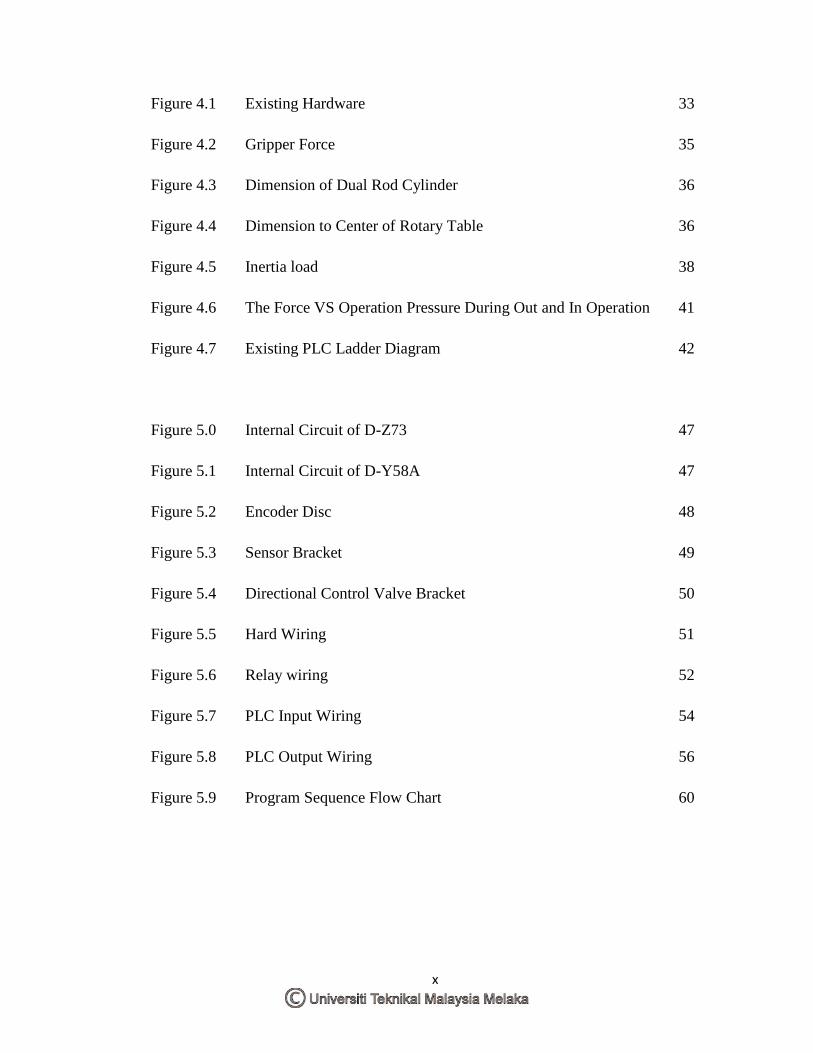
Figure 4.1 Existing Hardware 33
Figure 4.2 Gripper Force 35
Figure 4.3 Dimension of Dual Rod Cylinder 36
Figure 4.4 Dimension to Center of Rotary Table 36
Figure 4.5 Inertia load 38
Figure 4.6 The Force VS Operation Pressure During Out and In Operation 41
Figure 4.7 Existing PLC Ladder Diagram 42
Figure 5.0 Internal Circuit of D-Z73 47
Figure 5.1 Internal Circuit of D-Y58A 47
Figure 5.2 Encoder Disc 48
Figure 5.3 Sensor Bracket 49
Figure 5.4 Directional Control Valve Bracket 50
Figure 5.5 Hard Wiring 51
Figure 5.6 Relay wiring 52
Figure 5.7 PLC Input Wiring 54
Figure 5.8 PLC Output Wiring 56
Figure 5.9 Program Sequence Flow Chart 60
xi
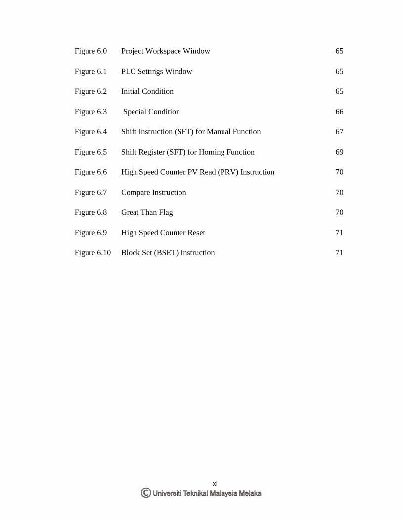
Figure 6.0 Project Workspace Window 65
Figure 6.1 PLC Settings Window 65
Figure 6.2 Initial Condition 65
Figure 6.3 Special Condition 66
Figure 6.4 Shift Instruction (SFT) for Manual Function 67
Figure 6.5 Shift Register (SFT) for Homing Function 69
Figure 6.6 High Speed Counter PV Read (PRV) Instruction 70
Figure 6.7 Compare Instruction 70
Figure 6.8 Great Than Flag 70
Figure 6.9 High Speed Counter Reset 71
Figure 6.10 Block Set (BSET) Instruction 71
xii
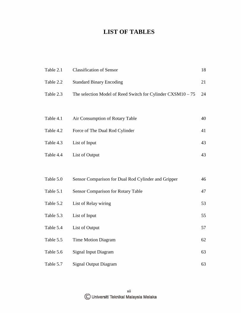
LIST OF TABLES
Table 2.1 Classification of Sensor 18
Table 2.2 Standard Binary Encoding 21
Table 2.3 The selection Model of Reed Switch for Cylinder CXSM10 – 75 24
Table 4.1 Air Consumption of Rotary Table 40
Table 4.2 Force of The Dual Rod Cylinder 41
Table 4.3 List of Input 43
Table 4.4 List of Output 43
Table 5.0 Sensor Comparison for Dual Rod Cylinder and Gripper 46
Table 5.1 Sensor Comparison for Rotary Table 47
Table 5.2 List of Relay wiring 53
Table 5.3 List of Input 55
Table 5.4 List of Output 57
Table 5.5 Time Motion Diagram 62
Table 5.6 Signal Input Diagram 63
Table 5.7 Signal Output Diagram 63

xiii
Table 6.1 Function of Bits in SFT for Manual Function 68
Table 6.2 Function of Bits in SFT for Homing Fuction 69

xiv
LIST OF ABBREVIATIONS, SYMBOLS AND NOMENCLATURE
CNC - Computer Numerical Control
PLC - Programmable Logic Controller
a - Safety Margin
ƒ - Force
g - Gravitational Acceleration
I/O - Input and Output
I - Moment of Inertia
kg - Kilogram
m - Mass
cm - Centimeter
mm - Mili-meter
mJ - Milli-joule
MPa - Mega Pascal
N - Newton
Nm - Newton Meter
VAC - Alternative Voltage
VDC - Direct Voltage

xv
µ - Coefficient of Friction
ω - Angular Acceleration
1
CHAPTER 1 INTRODUCTION
1.1 Background
Nowadays, robots play an important role in industry. They can replace human labor in
highly hazardous situations, especially in the processes of nuclear clean-up, dismantling
and decontamination (Caldwell, 1999). In the industry field, robot manipulator arm is a
most common industrial robot to perform the pick-and-place operation. Industrial robots
have used three primary actuator types: electric motors (DC or AC), hydraulic cylinders
and pneumatic cylinders (Caldwell, 1989). Mostly, the controlled motion was done using
electric motors and computers due to powerful if compare with other forms of actuation
have become practical for providing motion. But in term of cost, there is not economical
and need more experience in programming.
Pneumatic actuators are widely using in robotic systems due to low cost, quickness of
response and high power with low weight, power and high volume ratios (Henke, 1970).
Moreover, it has a high payload-to-weight ratio that is especially important for pick and
place task. They are also clean, easy to work with, and lightweight. In addition,
compressed air is readily available at nearly every industrial facility. Unfortunately,
position stabilization of a pneumatic actuator is difficult during the motion with high
accuracy at the desired positioning.
2
A hierarchical close loop feedback control for pneumatic manipulators is proposed to
overcome this type of problem. Where the flow of the actuator is controled for velocity,
speed, and air consumption. An electrical signal to the controller is conduct as a feed
back to the close loop system for read the positioning of the manipulator.
1.2 Objective
The purpose of this project is to have an accuracy study on the positioning of the pick
and place manipulator trainer. Thus, the following are the objectives of this project:
a) To identify the specification and function of the existing hardware.
b) To understand the sequence of the manipulator trainer.
c) To analyse the correct position for each motion.
d) To ensure the programming in order to control the manipulator trainer.
1.3 Scope
The scope of this invention cum study will be covering the following:
a) Analysis the existing and improve hardware by come out result in graphical form.
b) Redesign and apply the suitable electrical circuit.
c) Select suitable component and device.
d) Develop a fluent sequence control system and system operation.
e) Program the PLC for increase the stability of the system.
3
1.4 Problem Statements
Through the observation and testing for the existing manipulator trainer, there were
some problems and limitations as below:
a) Manipulator just can run for one cycle only.
b) All of the input signals are using mechanical type sensor with mechanical part for
sensing the path.
c) The accuracy, repeatability, and stability are out of effectiveness because using the
mechanical part to fix the limit of manipulator path.
d) The position of the manipulator cannot reset for homing when is needed.
e) When the OFF button is press emergency, the manipulator still in running condition.
f) Once the ON and OFF button is press equally, still can operate the manipulator is
cause of improper interlock in the programming.
4
CHAPTER 2 LITERATURE REVIEW
2.1 Introduction to Control Design
Robot is a re-programmable, multifunction manipulator designed to move material, parts,
tools, or specialized devices through variable programmed motions for the performance
of a variety of tasks. It usually consisting of a series of segments, jointed or sliding
relative to one another, for the purpose of grasping and moving objects usually and
several degrees of freedom. It may be remotely controlled by a computer or controller.
Controllers are the most important components in a robot system. If a robot has n joints,
n controller are needed to control all joint actuators. The design of robot control is to
solve the problem how robot’s actuators are driven to achive a desire performance. A
robot control system is actually the intergration of electonic hardware and computer
control software.
Marco A.M (1990) discovered that high accuracy is generally unachievable in
manipulators capable of producing high task forces due to such factors as high joint,
actuator, and transmission friction and link elastic and geometric distortions (Marco A.
M, 1990). To overcome this limitation, a suitable control system in the pick and place
manipulator system should be selected.
5
Controller Input or Reference
Process or Plant
Output or Controlled variable
These are the terms for select of control system in robotics, as ( Asfahl C.R, 1985):
a) Control resolution
Capability of robot's positioning system to divide the motion range of each joint
into closely spaced points.
b) Accuracy
Capability to position the robot's wrist at a desired location in the workspace, given
the limits of the robot's control resolution.
c) Repeatability
Capability to position the wrist at a previously taught point in the workspace.
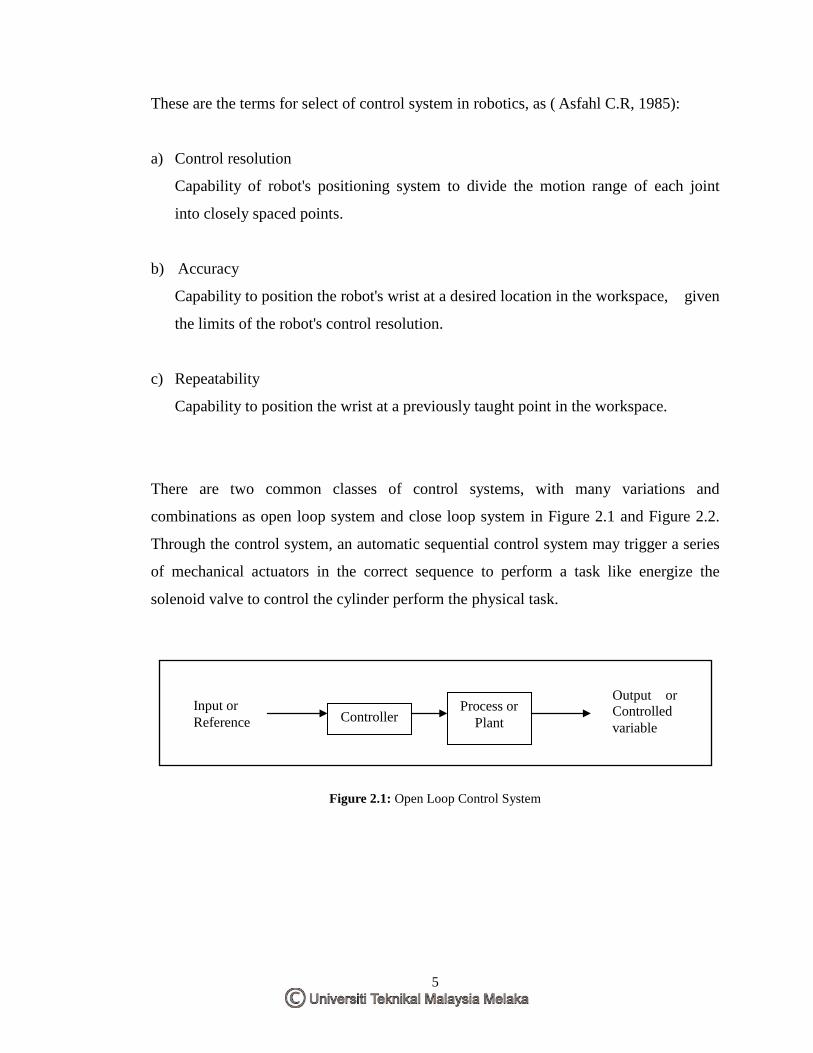
There are two common classes of control systems, with many variations and
combinations as open loop system and close loop system in Figure 2.1 and Figure 2.2.
Through the control system, an automatic sequential control system may trigger a series
of mechanical actuators in the correct sequence to perform a task like energize the
solenoid valve to control the cylinder perform the physical task.
Figure 2.1: Open Loop Control System