Embed Size (px)
Citation preview

1
VHDLMIPS32
EL 310Erkay Savaş
Sabancı University

2
MIPS32 Architecture• 32 bit architecture
– registers, ALU, instructions, shifter, data and address are 32 bit
• Load/Store architecture– There are special instructions to access memory
such as lw (load word) and sw (store word)– No ALU operation involves an operand from the
memory.• RISC based
– simple instructions– most of the instruction can be completed in five
clock cycles
3
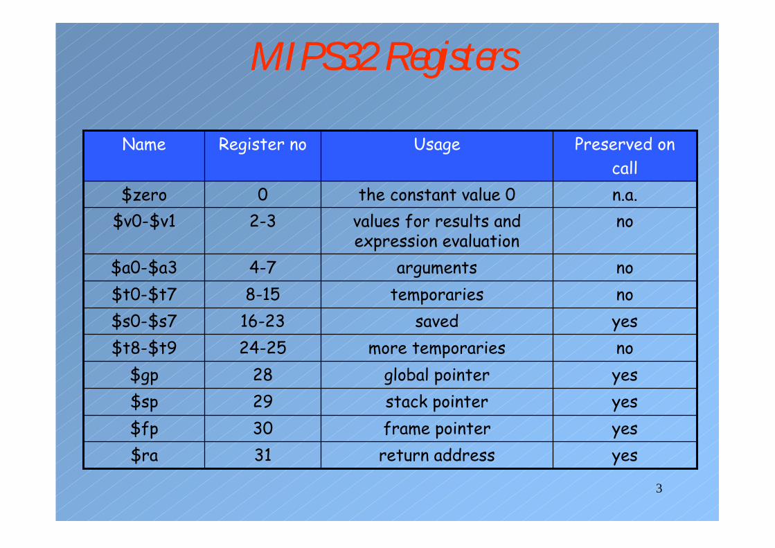
MIPS32 Registers
yesreturn address31$rayesframe pointer30$fpyesstack pointer29$spyesglobal pointer28$gpnomore temporaries24-25$t8-$t9yessaved16-23$s0-$s7notemporaries8-15$t0-$t7noarguments4-7$a0-$a3
novalues for results and expression evaluation
2-3$v0-$v1n.a.the constant value 00$zero
Preserved on call
UsageRegister noName
4
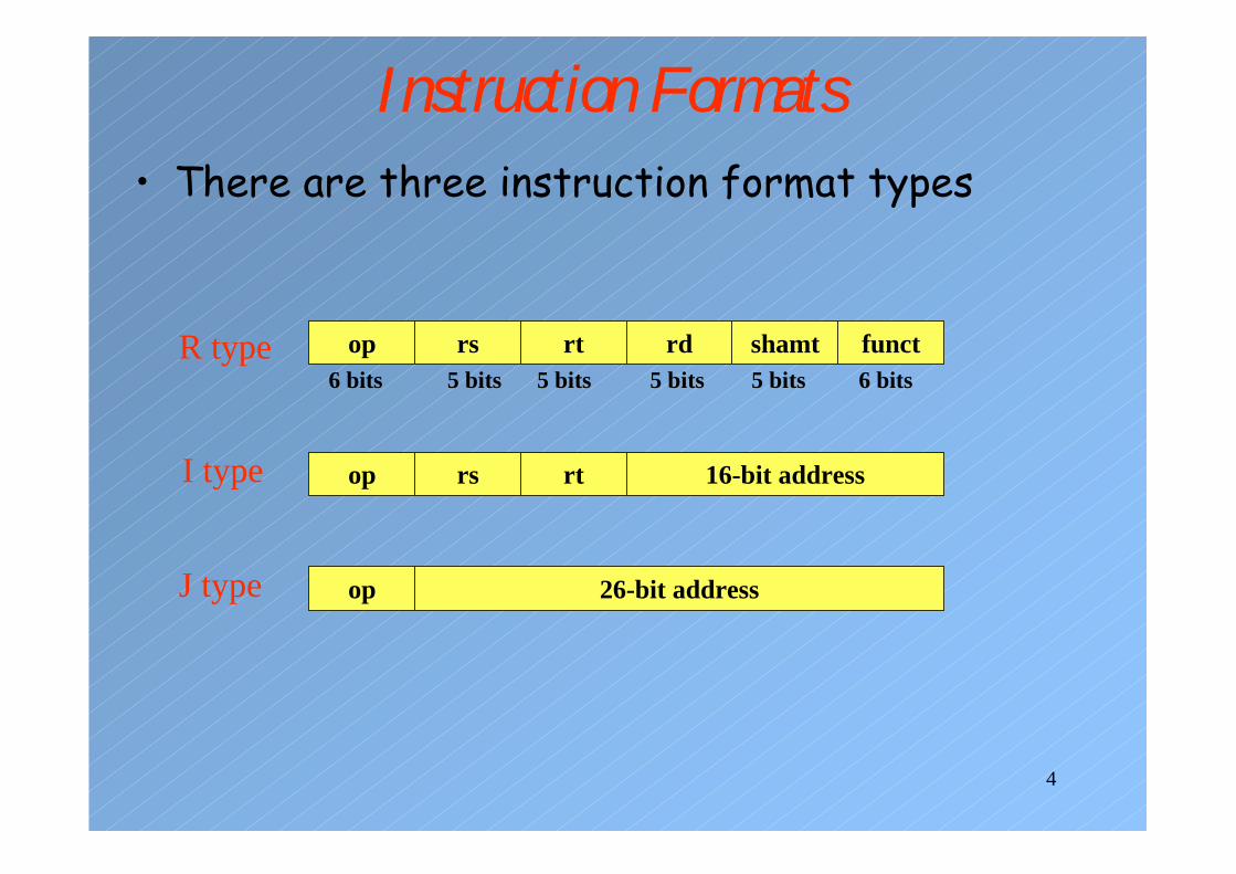
Instruction Formats• There are three instruction format types
op rs rt rd shamt funct6 bits 5 bits 5 bits 5 bits 5 bits 6 bits
R type
op rs rt 16-bit addressI type
op 26-bit addressJ type
5
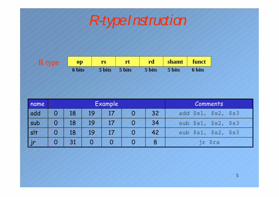
R-type Instruction
op rs rt rd shamt funct6 bits 5 bits 5 bits 5 bits 5 bits 6 bits
R type
sub $s1, $s2, $s34201719180sltsub $s1, $s2, $s33401719180subadd $s1, $s2, $s33201719180add
CommentsExamplename
jr $ra8000310jr

6
I-type Instruction
op rs rt 16-bit addressI type
bne $s1, $s2, 100Immediate18175bnebeq $s1, $s2, 100Immediate18174beqsw $s1, 100($s2)Immediate171843swlw $s1, 100($s2)Immediate171835lw
CommentsExamplename

7
Addressing Modes
op rs rt 16-bit address
register
data memory
lw $s1, index($s2)
Base addressing
op rs rt 16-bit address
PC
instruction memory
beq $s1, $s2, Loop
PC-relative addressing

8
instruction memory
j Address
J-type Instructions
op 26-bit addressJ type
op 26-bit address
PC
word
Pseudo-direct addressing
jal 10000Immediate3jalj 10000Immediate2jCommentsExamplename
9
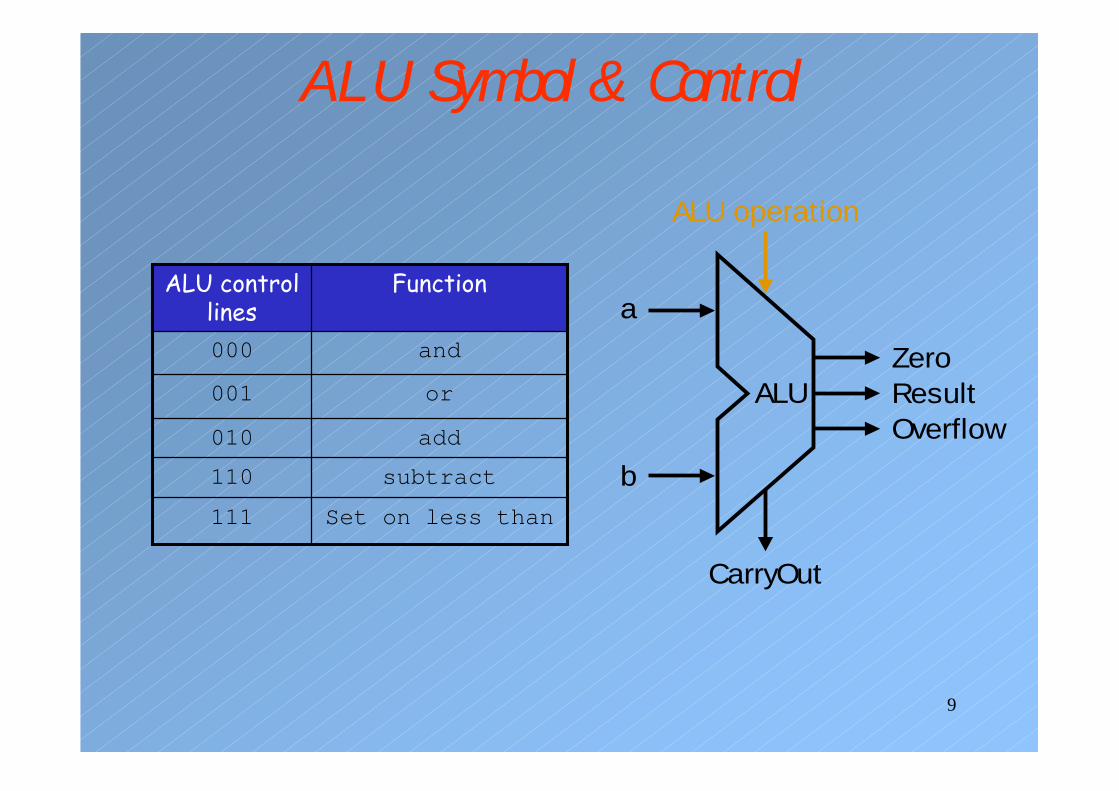
ALU Symbol & Control
ALU ResultZero
Overflow
a
b
ALU operation
CarryOut
Set on less than111
subtract110
add010
or001
and000
FunctionALU control lines

10
Implementing Instruction Fetch
PC
Instructionmemory
Readaddress
Instruction
4
Add
11
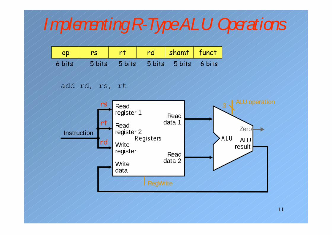
Implementing R-Type ALU Operationsop rs rt rd shamt funct
6 bits 5 bits 5 bits 5 bits 5 bits 6 bits
InstructionRegisters
Writeregister
Readdata 1
Readdata 2
Readregister 1
Readregister 2
Writedata
ALUresult
ALUZero
RegWrite
ALU operation3rs
rt
rd
add rd, rs, rt
12
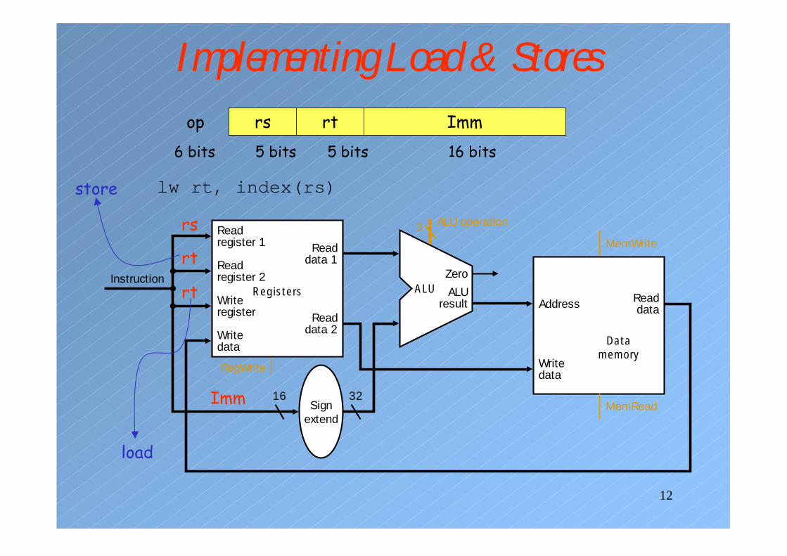
Implementing Load & Stores
Instruction
16 32
RegistersWriteregister
Readdata 1
Readdata 2
Readregister 1
Readregister 2
Datamemory
Writedata
Readdata
Writedata
Signextend
ALUresult
ZeroALU
Address
MemRead
MemWrite
RegWrite
ALU operation3
op rs rt Imm6 bits 5 bits 5 bits 16 bits
rs
rt
Imm
lw rt, index(rs)
rt
load
store

13
Implementing Branches
16 32Sign
extend
ZeroALU
Sum
Shiftleft 2
To branchcontrol logic
Branch target
PC + 4 from instruction datapath
Instruction
Add
RegistersWriteregister
Readdata 1
Readdata 2
Readregister 1
Readregister 2
Writedata
RegWrite
ALU operation3
op rs rt Imm6 bits 5 bits 5 bits 16 bits
rs
rt
Imm
multiply by 4
beq rs, rt,Label

14
Building the DatapathIdea: Use multiplexors to stitch them together
MemtoReg
MemRead
MemWrite
ALUOp
ALUSrc
RegDst
PC
Instructionmemory
Readaddress
Instruction[31–0]
Instruction [20–16]
Instruction [25–21]
Add
Instruction [5–0]
RegWrite
4
16 32Instruction [15–0]
0Registers
WriteregisterWritedata
Writedata
Readdata 1
Readdata 2
Readregister 1Readregister 2
Signextend
ALUresult
Zero
Datamemory
Address Readdata M
ux
1
0
Mux
1
0
Mux
1
0
Mux
1
Instruction [15–11]
ALUcontrol
Shiftleft 2
PCSrc
ALU
Add ALUresult

15
Control• Control Signals
– Selecting the operations to perform (ALU, load/store, beq, etc.)
– Controlling the flow of data (multiplexor’s select inputs)– Read/write enable inputs of memory and register file
• Information comes from the 32 bits of the instruction

16
ALU Control Unit• ALU performs
– addition for loads and stores– subtraction for branches (beq)– no operation for jumps– or the operation is determined by the function field
for R-type of information.• ALU Control unit will have the following inputs:
– two-bit control field called ALUOp– and Function field
17
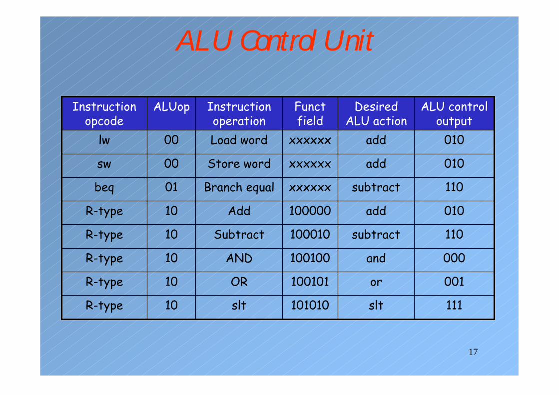
ALU Control Unit
111slt101010slt10R-type
001or100101OR10R-type
000and100100AND10R-type
110subtract100010Subtract10R-type
010add100000Add10R-type
110subtractxxxxxxBranch equal01beq
010addxxxxxxStore word00sw
010xxxxxx00 addLoad wordlw
ALU control output
Desired ALU action
Funct field
Instruction operation
ALUopInstruction opcode

18
Truth Table for ALU Control Unit
1110101XXX1
0011010XXX1
0000010XXX1
1100100XXX1
0100000XXX1
110XXXXXX1X
010XXXXXX00
F0F1F2F3F4F5ALUOp0ALUOp1 OperationFunct fieldALUOp
You can map the truth table to gates

19
Implementing the Control
• ALU Control Block
F0
F(5-0)Operation
ALUOp
Operation(0)
Operation(2)
Operation(1)
F1
F2
F3
ALUOp(0)
ALUOp(1)
20
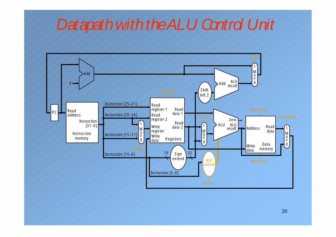
Datapath with the ALU Control Unit
MemtoReg
MemRead
MemWrite
ALUOp
ALUSrc
RegDst
PC
Instructionmemory
Readaddress
Instruction[31–0]
Instruction [20–16]
Instruction [25–21]
Add
Instruction [5–0]
RegWrite
4
16 32Instruction [15–0]
0Registers
WriteregisterWritedata
Writedata
Readdata 1
Readdata 2
Readregister 1Readregister 2
Signextend
ALUresult
Zero
Datamemory
Address Readdata M
ux
1
0
Mux
1
0
Mux
1
0
Mux
1
Instruction [15–11]
ALUcontrol
Shiftleft 2
PCSrc
ALU
Add ALUresult
21
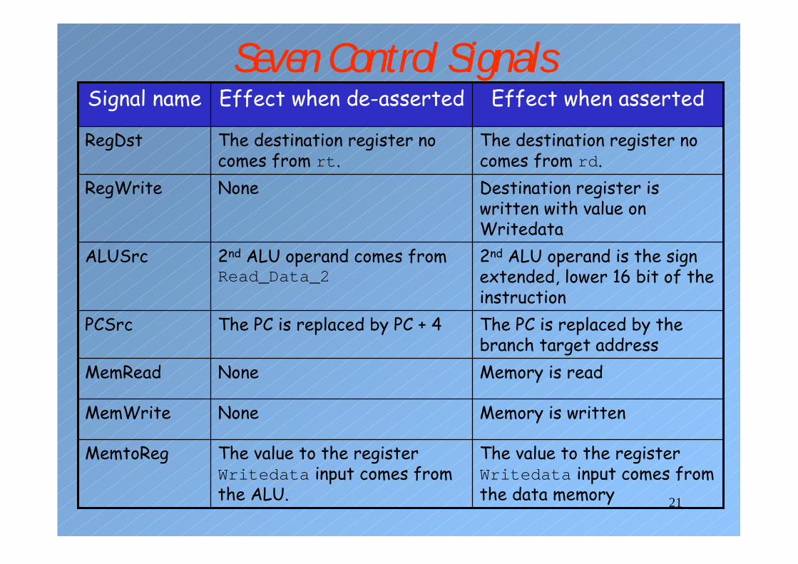
Seven Control Signals
The value to the register Writedata input comes from the data memory
The value to the register Writedata input comes from the ALU.
MemtoReg
Memory is writtenNoneMemWrite
Memory is readNoneMemRead
The PC is replaced by the branch target address
The PC is replaced by PC + 4PCSrc
2nd ALU operand is the sign extended, lower 16 bit of the instruction
2nd ALU operand comes from Read_Data_2
ALUSrc
Destination register is written with value on Writedata
NoneRegWrite
The destination register no comes from rd.
The destination register no comes from rt.
RegDst
Effect when assertedEffect when de-assertedSignal name

22
RegDst & RegWrite
read register #1
read register #2
writeregisterwrite data
Register file
read #1
Writeread #2
RegWriteRegDst
0
1
rt: Ins[20-16]
load
rd: Ins[15-11]
R-type

23
ALUSrc
read register #1
read register #2
writeregisterwrite data
Register file
read #1
read #2
RegWrite
ALUSrc
32
signextend
0
1
Imm: Ins[15-0]
16
result
Zero
ALU
24
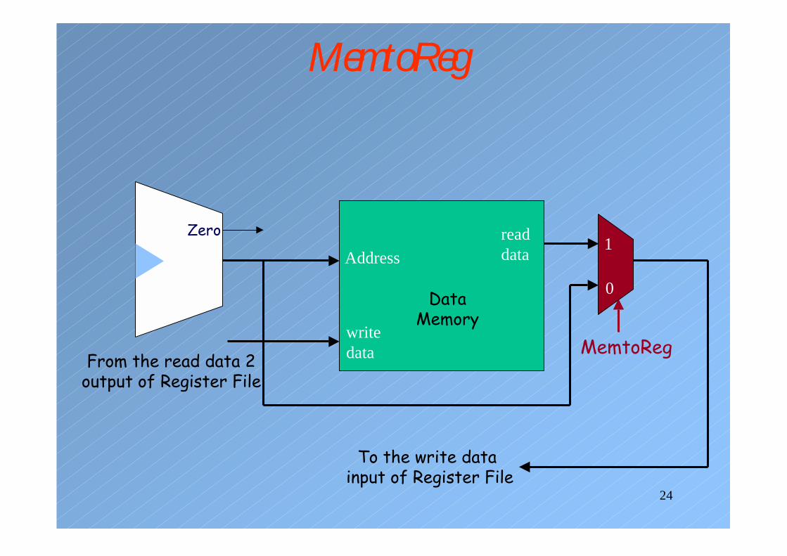
MemtoReg
Address
write data
DataMemory
read data
MemtoReg
1
0
Zero
To the write data input of Register File
From the read data 2output of Register File

25
PCSrc
PC
0
1
Imm: Ins[15-0]
Add
Shiftleftby 2 32
signextend
Add4
PcSrc
zerobranch

26
Datapath & Control
PC
Instructionmemory
Readaddress
Instruction[31–0]
Instruction [20 16]
Instruction [25 21]
Add
Instruction [5 0]
MemtoReg
ALUOp
MemWrite
RegWrite
MemRead
BranchRegDst
ALUSrc
Instruction [31 26]
4
16 32Instruction [15 0]
0
0Mux
0
1
Control
Add ALUresult
Mux
0
1
RegistersWriteregister
Writedata
Readdata 1
Readdata 2
Readregister 1
Readregister 2
Signextend
Mux1
ALUresult
Zero
PCSrc
Datamemory
Writedata
Readdata
Mux
1
Instruction [15 11]
ALUcontrol
Shiftleft 2
ALUAddress

27
Operation of the Datapath
101000X0Xbeq
000100X1Xsw
000011110lw
010001001R-format
ALUOp0
ALUOp1
BranchMemWrite
MemRead
RegWrite
Memto-Reg
ALUSrcRegDestInstruction
Example Flow: beq $s0, $s1, address• The instruction is fetched from memory and PC is incremented• Read two register values• Subtract one from the other, calculate the branch address• Use the zero signal to determine which of the addresses is to be
used for fetching the next instruction

28
Single Cycle Datapath
Instructionmemory
Address
4
32
0
Add Addresult
Shiftleft 2
Instruction
Mux
0
1
Add
PC
0Writedata
Mux
1Registers
Readdata 1
Readdata 2
Readregister 1
Readregister 2
16Sign
extend
Writeregister
Writedata
ReaddataAddress
Datamemory
1
ALUresult
Mux
ALUZero
IF: Instruction fetch ID: Instruction decode/register file read
EX: Execute/address calculation
MEM: Memory access WB: Write back
29
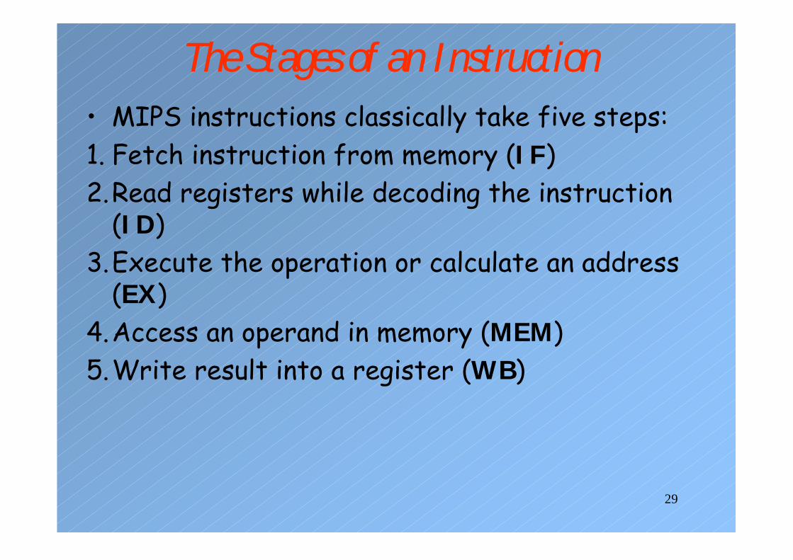
• MIPS instructions classically take five steps:1. Fetch instruction from memory (IF)2.Read registers while decoding the instruction
(ID)3.Execute the operation or calculate an address
(EX)4.Access an operand in memory (MEM)5.Write result into a register (WB)
The Stages of an Instruction

30
Times of Different Instruction Steps
5 ns2 ns1ns2 nsBranch6 ns1 ns2 ns1ns2 nsR-format7 ns2 ns2 ns1ns2 nssw
1 ns2 ns2 ns1ns2 ns 8 nslw
Total timeRegister write
Data access
ALUop
Register Read
Inst. Fetch
Instruction class
Clock period that can be used in single-cycle implementation will be 8 ns for all instruction.

31
Pipelined vs. Nonpipelined
Time 2 4 6 8 10 12 14 16 18Program execution
order
IF ID EX MEMWB
IF ID EX MEMWB
IF
lw $t1, 100($s1)
lw $t2, 200($s1)
lw $t2, 300($s1)
lw $t1, 100($s1)
lw $t2, 200($s1)
lw $t2, 300($s1)
Time 2 4 6 8 10 12 14 16 18Program execution
order
IF EX MEMID WB
EX MEMIDIF WB
EX MEMIDIF WB

32
Design of Pipelined Datapath• Break the datapath into smaller segments • Portions of datapath can be shared by
instructions• Use registers between two consecutive
segments of the datapath to hold the intermediate results.
• Pipeline registers• Data transfer between the stages happens
through the pipeline registers

33
Pipelined Datapath

34
Example: IF of lw
Instruction Memory
PCRegisters Data
Memory
Add
Add
ALUMUX
MUX
MUX
4
SignExt
ShiftLeft
2
IF/ID ID/EX EX/MEM MEM/WB
16 32

35
Example: ID of lw
Instruction Memory
PCRegisters Data
Memory
Add
Add
ALUMUX
MUX
MUX
4
SignExt
ShiftLeft
2
IF/ID ID/EX EX/MEM MEM/WB
16 32
36
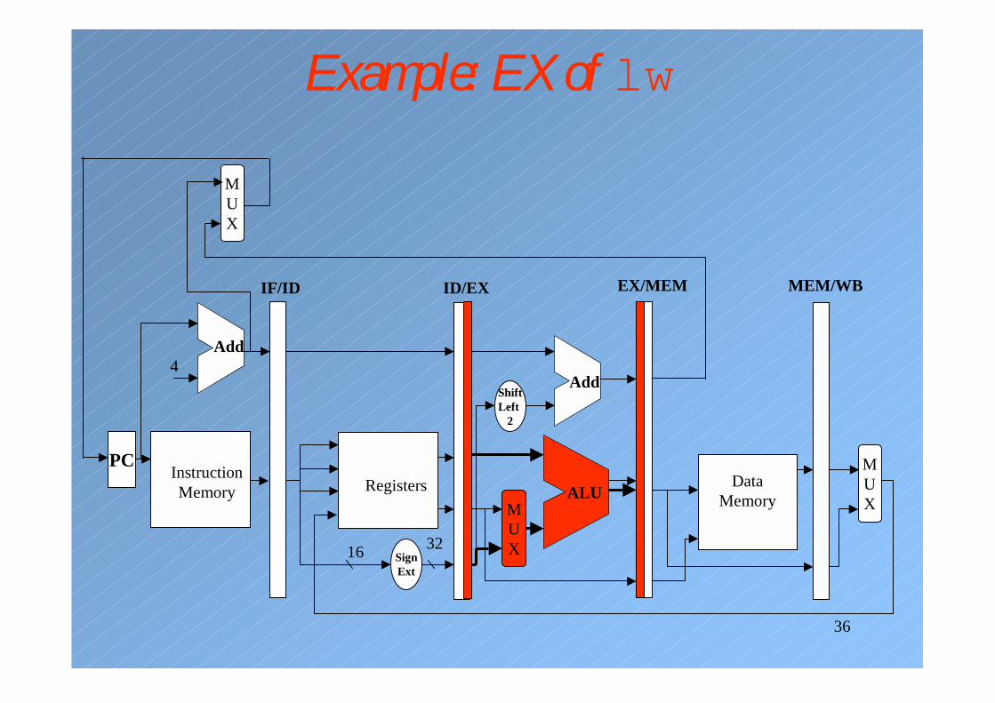
Example: EX of lw
Instruction Memory
PCRegisters Data
Memory
Add
Add
ALUMUX
MUX
MUX
4
SignExt
ShiftLeft
2
IF/ID ID/EX EX/MEM MEM/WB
16 32

37
Example: MEM of lw
Instruction Memory
PCRegisters
Add
Add
ALUMUX
MUX
MUX
4
SignExt
ShiftLeft
2
IF/ID ID/EX EX/MEM MEM/WB
16 32
DataMemory

38
Example: WB of lw
Instruction Memory
PC
Add
Add
ALUMUX
MUX
MUX
4
SignExt
ShiftLeft
2
IF/ID ID/EX EX/MEM MEM/WB
16 32
DataMemory
Registers

39
Corrected Datapath
Instruction Memory
PC
Add
Add
ALUMUX
MUX
MUX
4
SignExt
ShiftLeft
2
IF/ID ID/EX EX/MEM MEM/WB
16 32
DataMemory
Registers

40
Example 2: Store word, EX stage
Instruction Memory
PCRegisters Data
Memory
Add
Add
ALUMUX
MUX
MUX
4
SignExt
ShiftLeft
2
IF/ID ID/EX EX/MEM MEM/WB
16 32

41
Example 2: MEM of sw
Instruction Memory
PCRegisters
Add
Add
ALUMUX
MUX
MUX
4
SignExt
ShiftLeft
2
IF/ID ID/EX EX/MEM MEM/WB
16 32
DataMemory

42
Example 2: WB of sw
Instruction Memory
PCRegisters
Add
Add
ALUMUX
MUX
MUX
4
SignExt
ShiftLeft
2
IF/ID ID/EX EX/MEM MEM/WB
16 32
DataMemory
Oops! Nothing happening

43
Pipelined Control• PC is written on each clock cycle (no write
signal)• No write signals for pipeline registers.• IF stage: no control signal since instruction is
read and PC is updated each cycle• ID stage: No control signals• EX stage: RegDst, ALUOp, ALUSrc
• MEM stage: branch, MemRead, MemWrite
• WB stage: MemtoReg, RegWrite

44
Pipelined Datapath with Control Signals
Instruction Memory
PC Registers
Add Add
ALUMUX
MUX
4
SignExt
ShiftLeft
2
IF/IDID/EX EX/MEM MEM/WB
16 32
DataMemory
ALUcntrl
[15 0]
[20 16][15 11]
MUX
MUX
branch
ALUSrc
RegDst
ALUOp
PCSrc
zeroMemWrite
MemRead
RegWrite
MemtoReg
6
rd
rt

45
Reminder: Seven Control Signals
The value to the register Writedata input comes from the data memory
The value to the register Writedata input comes from the ALU.
MemtoRegMemory is writtenNoneMemWriteMemory is readNoneMemRead
The PC is replaced by the branch target address
The PC is replaced by PC + 4PCSrc
2nd ALU op is the sign extended, lower 16 bit of the instruction
2nd ALU op comes from Read data 1 (i.e. rt)
ALUSrc
Destination register is written with value on Writedata
NoneRegWrite
The destination register number comes from rd.
The destination register number comes from rt.
RegDst
Effect when assertedEffect when deassertedSignal name

46
Control Signals for Instructions• Nine control signals that start in the EX stage• Main control unit generates the control signals
during the ID stage.
WB StageMEM StageEX Stage
x0001010xbeq
x0100100xsw
110101000lw
010000011R-format
Memto-Reg
RegWrite
MemWrite
MemRead
BranchALUSrc
ALUOp0
ALUOp1
RegDestInstruction

47
Control Lines for the Last Three Stages
IF/ID
EX
MEM
WB
ID/EX EX/MEM MEM/WB
MEM
WB
WB
Controlinstruction

48
Pipelined Datapath with Control Signals
Instruction Memory
PC Registers
Add Add
ALUMUX
4
SignExt
ShiftLeft
2
IF/ID
ID/EX EX/MEM
MEM/WB
16 32
DataMemory
ALUcntrl
[15 0]
[20 16]
[15 11]MUX
MUX
branch
ALUSrc
RegDst
ALUOp
PCSrc
zeroMemWrite
MemRead
RegWriteMemtoReg
EX
M
WB
M
WB
WB
MUX
Control

49
Example• Show these five instructions going through the
pipeline:
lw $10, 20($1)sub $11, $2, $3and $12, $4, $5or $13, $6, $7add $14, $8, $9
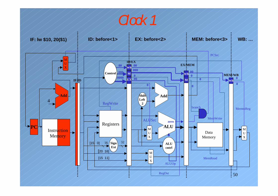
50
Clock 1IF: lw $10, 20($1)
PC Registers
Add Add
ALUMUX
4
SignExt
ShiftLeft
2
IF/ID
ID/EXEX/MEM
MEM/WB
16 32
DataMemory
ALUcntrl
[15 0]
[20 16]
[15 11]MUX
MUX
branch
ALUSrc
RegDst
ALUOp
PCSrc
zeroMemWrite
MemRead
RegWriteMemtoReg
EX
M
WB
M
WB
WB
MUX
Instruction Memory
00
0000000
00000
000
0
000
0
0 0
0
ID: before<1> EX: before<2> MEM: before<3> WB: …
Control
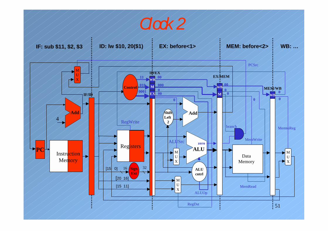
51
Clock 2IF: sub $11, $2, $3
PC
Add Add
ALUMUX
4
SignExt
ShiftLeft
2
IF/ID
ID/EXEX/MEM
MEM/WB
16 32
DataMemory
ALUcntrl
[15 0]
[20 16]
[15 11]MUX
MUX
branch
ALUSrc
RegDst
ALUOp
PCSrc
zeroMemWrite
MemRead
RegWriteMemtoReg
EX
M
M
WB
WB
MUX
Instruction Memory
11
0100001
00
000000
0
000
00
0
0
ID: lw $10, 20($1) EX: before<1> MEM: before<2>
Registers
WB
Control
WB: …

52
Clock 3IF:and $12, $4, $5
PC
Add Add
ALUMUX
4
SignExt
ShiftLeft
2
IF/ID
ID/EXEX/MEM
MEM/WB
16 32
DataMemory
ALUcntrl
[15 0]
[20 16]
[15 11]MUX
MUX
branch
ALUSrc
RegDst
ALUOp
PCSrc
zeroMemWrite
MemRead
RegWriteMemtoReg
EX
M
M
WB
WB
MUX
Instruction Memory
10000
1100
11
010000
1
000
00
0
0
ID: sub $11, $2, $3 EX: lw $10, 20($1) MEM: before<1> WB: …
Registers
WB
Control
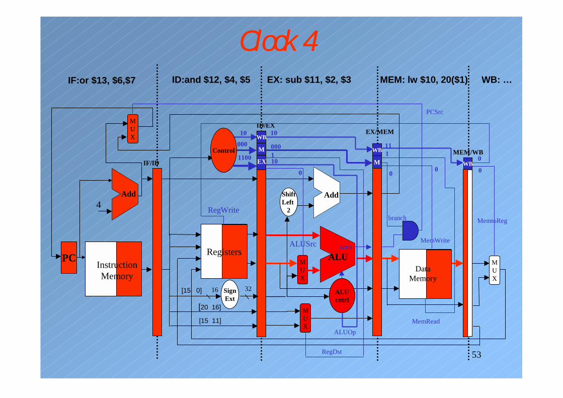
53
Clock 4IF:or $13, $6,$7
PC
Add Add
ALUMUX
4
SignExt
ShiftLeft
2
IF/ID
ID/EXEX/MEM
MEM/WB
16 32 ALUcntrl
[15 0]
[20 16]
[15 11]MUX
MUX
branch
ALUSrc
RegDst
ALUOp
PCSrc
zeroMemWrite
MemRead
RegWriteMemtoReg
EX
M
M
WB
WB
MUX
Instruction Memory
10000
1100
10
000110
0
111
00
0
ID:and $12, $4, $5 EX: sub $11, $2, $3 MEM: lw $10, 20($1) WB: …
Registers
WB
DataMemory
Control
0
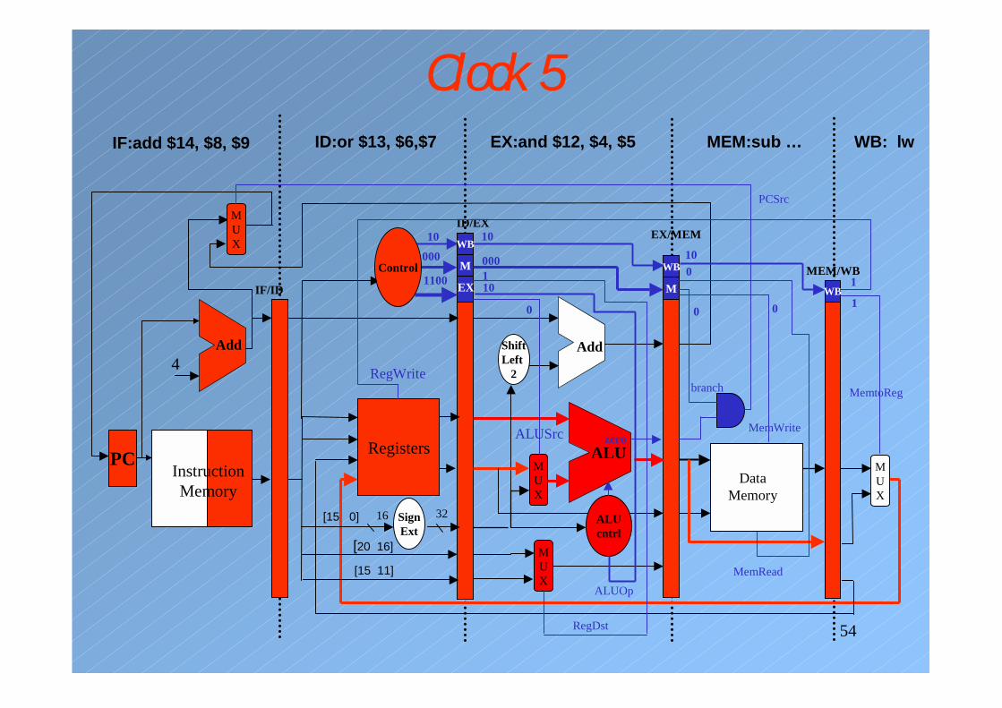
54
Clock 5IF:add $14, $8, $9
PC
Add Add
ALUMUX
4
SignExt
ShiftLeft
2
IF/ID
ID/EXEX/MEM
MEM/WB
16 32 ALUcntrl
[15 0]
[20 16]
[15 11]MUX
MUX
branch
ALUSrc
RegDst
ALUOp
PCSrc
zeroMemWrite
MemRead
RegWriteMemtoReg
EX
M
M
WB
WB
MUX
Instruction Memory
10000
1100
10
000110
0
100
0
1
1
ID:or $13, $6,$7 EX:and $12, $4, $5 MEM:sub … WB: lw
Registers
WB
DataMemory
Control
0

55
Example: Exception in the Pipelined Datapath• 0x40 sub $11, $2, $40x44 and $12, $2, $50x48 or $13, $2, $60x4C add $1, $2, $10x50 slt $15,$6, $70x54 lw $16,50($7)
• Suppose an overflow exception occurs in the addinstruction.
• Exception handling routine0x40000040 sw $25, 1000($0)0x40000044 sw $26, 1004($0)
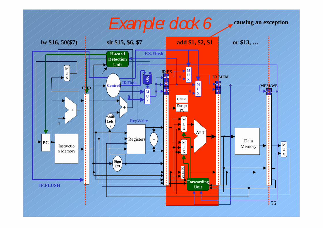
56
Example: clock 6
Instruction Memory
PCRegisters
+
ALU
MUX
4
SignExt
ShiftLeft
2
IF/ID
ID/EXEX/MEM
MEM/WB
DataMemory
MUX
MUX
RegWrite
EX
M
WB
ControlM
WB
WB
MUX
HazardDetection
Unit
=
ForwardingUnit
+
MUX
0
MUX
IF.FLUSH
OR
ID.Flush
MUX
MUX
0
0
EX.Flush
ExceptPC
Cause
lw $16, 50($7) slt $15, $6, $7 add $1, $2, $1 or $13, …
causing an exception

57
Example: clock 7
Instruction Memory
PCRegisters
+
ALU
MUX
4
SignExt
ShiftLeft
2
IF/ID
ID/EXEX/MEM
MEM/WB
DataMemory
MUX
MUX
RegWrite
EX
M
WB
ControlM
WB
WB
MUX
HazardDetection
Unit
=
ForwardingUnit
+
MUX
0
MUX
IF.FLUSH
OR
ID.Flush
MUX
MUX
0
0
EX.Flush
ExceptPC
Cause
sw $25, 1000($0) bubble bubble bubble or $13, …