Embed Size (px)
Citation preview

University of Asia Pacific Department of Civil Engineering
Mid Semester Examination Spring 2016 Program: B.Sc. Engineering (Civil)
Course Title: Transportation Engineering TI Time: 1 Hour
3. Answer any one {lXG = 6)
Course Code: CE 451 Full Marks: 20
a. The gradation required for a typical mix is given in Table 1 in column 1 and 2. The gradation of available for three types of aggregate A, B, and C are given in column 3, 4, and 5. Determine the proportions of A,B and C if mixed will get the required gradation in column 2.
Table 1
Sieve Size (mm) Required Gradation Filler Fine Aggregate Coarse Aggregate Range (A} (B} (C}
25.4 100 100 100 100
12.7 90-100 100 100 94
4.76 60-75 100 100 54
1.18 40-55 100 66.4 31.3
0.3 20-35 100 26 22.8
0.15 12-22 73.6 17.6 9
0.075 5-10 40.1 5 3.1
b. The following results were obtained by a mechanical sieve analysis . Classify the soil according to the AASHTO classification system and give the group index. State whether this material is suitable in its natural state for use as a subbase material.
Sieve Size % passing by Weight Liquid Limit= 33
No. 4 30 Plastic Limit= 12
No. 40 40
No. 200 30
AASTHO Classification of Soils and Soil Aggregate Mixtures
General Classification General Materials (35% or Im pa;sing O.Oi5 nun) Silt.clay materials (more than 3 5% passing
00i5 nun) A-1 A·2 A-i
Group Classification A-1 -a A-1-b
A-3 A-2--1 A- 2-5 A-2·6 A-2-7
A-4 A.5 A-6 A-7·5 A·i -6
Sim Analysis % passing 2 .00 nun (No I 0) 50ma., 0 .425 nun (No40) 30max 50max 51 min 0.725 nm1 (No200) 15max 25max !Oma., 35max 35max 35max 35max 36min 36min 36min 36min
Characteristics of fraction pmmg 6max
Liquid limit NP .JOmax 4lmin .\Onux .\I min .\Omax .\!min .J Omax .\Omin Plastic Index IOnm !Onux !!min !!min !Omax IOmax !!min llmin
Usual types of significant Stone fragment Fme Silty or clayey Gra \'el and sand Constituent material Gra I'd and sand Sand Siltv soils Clavev soils
General rating Excellent to Good Fair to ooor

University of Asia Pacific Department of Civil Engineering
Mid Semester Examination Spring 2016 Program: B.Sc. Engineering (Civil)
Course Title: Transportation Engineering II Time: 1 Hour
1. Answer any 5 {SX2 =10}
a. How flexible and rigid pavement differ in load spreading capability?
b. What is Atterberg Limit?
Course Code: CE 451 Full Marks: 20
c. What is the permeability of soil? Characterize loose soil and dense soil in terms of
permeability?
d. For measuring the resistance of aggregates to weathering action, which of test will you
conduct? Which property of aggregate is tested by conducting aggregate impact test?
e. What is well graded bituminous mix?
f . What is bituminous mix design?
g. What does Marshall Stability measure?
2. Answer any 1 {1X4 = 4)
a. The results of Marshall test for five specimen is given in Table 1. Find the optimum bitumen
content of the mix. Check the results with the specified test limit given in Table 2 and give
comment .
Table 1: Marshall Test Data
Bitumen Stability Flow Air Void Voids Filled with Bulk Specific Content(%) (kg) (Unit) (%) Bitumen(%) Gravity of Mix
3 499.4 9 12.5 34 2.17
4 717.3 9.6 7.2 65 2.21
5 812.7 12 3.9 84 2.26
6 767.3 14.8 2.4 91 2.23
7 662.8 19.5 1.9 93 2.18
Table 2: Specified Test Limit
Test Property Specified Value
Marshall Stability (kg) 340 (minimum)
Flow Value, 0.25 mm 8-17
Air Void, % 3-5
Voids Filled with Bitumen,% 75-85
b. The specific gravities and weight proportions for aggregate and bitumen are as under for the
preparation of Marshall mix design . The volume and weight of one Marshall specimen was
found to be 475 cc and 1100 gm. Assuming absorption of bitumen in aggregate is zero, find
theoretical specific gravity of mix, bulk specific gravity of mix, percent of air void, voids in
mineral aggregate, voids filled with bitumen.

University of Asia Pacific Department of Civil Engineering
Mid Semester Examination Spring 2016 Program: B.Sc. Engineering (Civil)
Course Title: Transportation Engineering I1 Time: 1 Hour
1. Answer any 5 (5X2 =10)
a. How flexible and rigid pavement differ in load spreading capability?
b. What is Atterberg Limit?
Course Code: CE 451 Full Marks: 20
c. What is the permeability of soil? Characterize loose soil and dense soil in terms of
permeability?
d. For measuring the resistance of aggregates to weathering action, which of test will you
conduct? Which property of aggregate is tested by conducting aggregate impact test?
e. What is well graded bituminous mix?
f . What is bituminous mix design?
g. What does Marshall Stability measure?
2. Answer any 1 (1X4 = 4)
a. The results of Marshall test for five specimen is given in Table 1. Find the optimum bitumen
content of the mix. Check the results with the specified test limit given in Table 2 and give
comment.
Table 1: Marshall Test Data
Bitumen Stability Flow Air Void Voids Filled with Bulk Specific
Content(%) (kg) (Unit) (%) Bitumen(%) Gravity of Mix
3 499.4 9 12.5 34 2.17
4 717.3 9.6 7.2 65 2.21
5 812 .7 12 3.9 84 2.26
6 767.3 14.8 2.4 91 2.23
7 662.8 19.5 1.9 93 2.18
Table 2: Specified Test Limit
Test Property Specified Value
Marshall Stability (kg) 340 (minimum)
Flow Value, 0.25 mm 8-17
Air Void,% 3-5
Voids Filled with Bitumen, % 75-85
b. The specific gravities and weight proportions for aggregate and bitumen are as under for the
preparation of Marshall mix design. The volume and weight of one Marshall specimen was
found to be 475 cc and 1100 gm . Assuming absorption of bitumen in aggregate is zero, find
theoretical specific gravity of mix, bulk specific gravity of mix, percent of air void, voids in
mineral aggregate, voids filled with bitumen.

University of Asia Pacific Department of Civil Engineering
Mid Semester Examination Spring 2016 Program: B.Sc. Engineering (Civil)
Course Title: Transp011ation Engineering II Time: 1 Hour
3. Answer any one (1X6 = 6)
Course Code: CE 451 Full Marks: 20
a. The gradation required for a typical mix is given in Table 1 in column 1 and 2. The gradation of available for three types of aggregate A, B, and C are given in column 3, 4, and 5. Determine the proportions of A,B and C if mixed will get the requ ired gradation in column 2.
Table 1
Sieve Size (mm) Required Gradation Filler Fine Aggregate Coarse Aggregate Range (A) (B) (C)
25.4 100 100 100 100 12.7 90-100 100 100 94 4.76 60-75 100 100 54 1.18 40-55 100 66.4 31.3 0.3 20-35 100 26 22.8
0.15 12-22 73.6 17.6 9 0.075 5-10 40.1 5 3.1
b. The following results were obtained by a mechanical sieve analysis. Classify the soil according to the AASHTO classification system and give the group index. State whether this material is suitable in its natural state for use as a subbase material.
Sieve Size % passing by Weight Liquid Limit= 33 1-----~~~~~~~~--1--~~~~~~~~~~~-1
No. 4 30 Plastic Limit= 12 No. 40 40 No. 200 30
AASTHO Classification of Soils and Soil Aggregate Mixtures
General Classification General Materials (35% or less prning 0.075 nm1) Silt-clay materials (more than 3 5% passing
0.0 75 nm1) A-1 I I A-2 l L I A-7
c. .. . ~ Cl, ,,; f; a. ,;a., ~ .... ---l~ . .. -. _ . 1 ~ l e~ l - L I ! ,I ' ; ' ' I 1 ~

University of Asia Pacific Department of Civil Engineering
Midterm Examination Spring 2016 Program: B.Sc. Engineering (Civil)
Course code: CE 461 Course title: Irrigation and Flood Control
Time: 60 Minutes Total marks: 20
Answer all questions
I. What are the harmful effects of excess irrigation?
2. Estimate depth of ground water evaporation that may turn a 33 cm depth of soil
saline over a period of 5 months. The electrical conductivity of groundwater is 5
mmhos/cm. The electric conductivity (EC) value of saturated extract of soil is I
mmhos/cm. The soil has a mean bulk density of 1.45 g/cm3 and saturation point of
40 percent. The density of water is assumed as I g/cm3.
3
3. Explain "Furrow Irrigation" and "Sprinkler Irrigation"? Which one is preferred in 3
Bangladesh and why?
4. Determine the time required to irrigate a strip of land containing clay loam soil
from a tube-well with a discharge of 0.20 m3/s by using border flooding method.
The infiltration capacity of the soil may be taken as 3 cm/hand the average depth
of flow on the field as 10 cm. Also determine the maximum area that can be
irrigated from this tube well. Assume any missing data.
4
5. Explain the following: i) Flood; ii) Polder; iii) Haor; iv) Integrated Water 4
Resources Management
6. Explain the impacts of floods . 2
7. What are the structural and non-structural measures of flood control and 3
management in Bangladesh?

University of Asia Pacific Department of Civil Engineering
Mid Semester Examination Spring 2016 (Set Al) Course #: CE 411 Full Marks: 40 (= 4 x 10)
Course Title: Structural Engineering Ill Time: 1 hour
I. Use Stiffness Method to calculate the deflections at joints e and g of the 2D truss loaded as shown in f.i&_l (Given : P = 30 kN , Q = 29 kN , Sx = constant = IO kN/mm].
a
j
I I 7m 4m 6m
6m
!Om
!Om
!Om
6m
4m 7m
Guided Rollers ate and g
2. Use Stiffness Method (neglecting axial deformations) to calculate the bending moment at joint d and/ of member dfofthe frame loaded as shown in Fig. 2 [Given: w = 30 kN/m, EI= constant= 29,000 kN-m2
].
3. For the 3D truss abcdefgh shown in .Ei&.J. (with given nodal coordinates)
(i) Use Stiffness Method to calculate the force F that causes joint c to deflect 0.1 O' leftwards .
( ii) Calculate the other deflections of joint c
[Given: S, = constant = 500 k/ft].
Nodal coordinates (ft) a(0 ,0,0), b(S ,0,0) , c(S ,0,-24), d(0,0,- 24) e(0 ,- 8,0), j(S,- 8,0), g(S ,- 8,- 24), h(0,- 8,- 24) .._ · - · - ·>X
4. (i) Determine degree of kinematic indeterminacy (doki) of the 30 frame shown in Fig. 4(i), considering boundary conditions and neglecting axial deformations.
(ii) Formulate stiffness matrix of the grid abed shown in .Eig,__1(jj} [Given: EI= 60,000 k-ft2 , GJ= 40,000 k-ft2
].
a....::::::----,..b--
e
Fig. 4(i)
z y +
~ ... . I
f-- 8' ~
Fig. 4(ii)

List of Useful Formulae for CE 411
* The stiffness matrix Km G of a 20 truss member in the global axis system is given by
G CS S2 -CS - S2 and Truss member force, P AB= S, [(u8- uA) C + (v8-v A) S] rC
2 CS -C
2 -CSJ
Km = S, C2 -CS C2 CS
-CS -S2 CS S2 [where C = cos 8, S = sin 8]
* Fixed End Reactions for One-dimensional Prismatic Members under Typical Loadings
PL/8 p PL/8 wL2/ 12 w wL2/12
D c, + + + t t t t ~) ~ ~
L/2 L
0~-: L/2
/2 P/2 wL/2 wL/2
4EI8/L 2EI8/L 6Eli'.i/L2 6Eli'.i/L2
D ~ ·· ·· ···· ~~ f 12Eli'.i/L3
. ~ '
6EI8/L2 12EIML0 6EI8/L2
* The stiffness matrices KAB of Beam AB and Column AB (for uA, vA, 8A, u8 , v8 , 88 ) are
Sx 0 0 -Sx 0 0 S1 0 S2 -Si 0 S2 0 S1 S2 0 -Si S2 0 s, 0 0 - S, 0
KBeam = 0 S2 S3 0 -S2 S4 Kco1umn= S2 0 S3 -S2 0 S4
-Sx 0 0 Sx 0 0 - Si 0 - S2 S1 0 -S2 0 -Si -S2 0 S1 -S2 0 - Sx 0 0 Sx 0 0 S2 S4 0 -S2 S3 S2 0 S4 - S2 0 S3
where S, = EA/L, S1 = 12EI/L3, S2 = 6EI/L2, S3 = 4EI/L, S4 = 2EI/L
* The stiffness matrix of a 3 D truss member in the global axes system [ using Cx = cos a , Cy= cos ~' C2 = cos y] is
c/ CyC,
czcx -C, z
-CyC, -C,C,
c,cz CyC, cz
z
-C,C2
-CyC2
-C,2
- Cx 2
-CyCx -czc, c, 2
CyC, C2C,
-CxCz -CyC2
-C,2
CxCz CyC2
c ,2
* Direction cosines of3D truss member C, = LjL, Cy= L/ L, C, = L/ L; where L = 'V[L/ + L/ + L,2]
* Member force P AB= S, [(u 8 -uA) C, + (v8-v A) Cy+ (w8-wA) C,]
* Torsional stiffness = GJ/L
* Doki for 20 Truss= 2j - r, 30 Truss = 3j - r, Grid = 3j - r, 20 Frame = 3j - r, 30 Frame= 6j - r

University of Asia Pacific Department of Civil Engineering
Mid Semester Examination SQring 2016 Program: B.Sc. Engineering (Civil)
Section B (Set 2)
Course Title: Structural Engineering III Time: 1 hour
Course Code: CE 411 Full Marks : 40 (= 4 x 10)
1. Ignore zero-force members and apply boundary conditions to formulate the stiffness matrix of the space truss ABCD shown in Fig.1 [Given: Sx =constant= 500 k/ft].
Nodal Coordinates (ft) are A(O, 0, 10), B(O, 0, 0) C(lO, 0, 0), 1)€0, 0, 10),
(?> 1 <'y, 0
1 ..... : .. .. .... >X
,:· z
~6'
) 10'
I 10'
E6'+-12'_j z /
y +
.. ···'""""> X
2. For the grid ABCDE loaded as shown in Fig.2, use the stiffness method to calculate the vertical deflection and rotations [Given : EI= 40 x 103 k-ft2, GJ= 30 x 103 k-ft2
].
3. For the frame shown ABCDE loaded as shown in Fig.3, calculate the unknown deflection and rotations neglecting axial deformation [Given: EI= 104 kN-m2
].
,. D T a e
4m
T 20 kN/m
-t I'. B 2m A 1 25 kN
4m
E 1 ~2m
~
~l.smtum+--3m-----1 Fig 4
Fig 3
4. Fig.4 shows a plane truss abcdefgh whose support g settles 10 mm due to the applied force P. Calculate (i) Axial force in all members, (ii) Applied force P [Given: Sx =constant= 5 kN/mm].

List of Useful Formulae for CE 411
* The stiffness matrix Km G of a 2D truss member in the global axis system is given by
~
C2
CS -C2
-CJ c cs s 2 -cs -s2
Km = Sx C2 -CS C2 CS
-cs -S2 cs S2 [where c = cos e, s = sin 9]
* Fixed End Reactions for One-dimensional Prismatic Members under Typical Loadings
PL/8 P PL/8 wL2/ 12 w
c ~---L---4-n l-u--------12
~) c ~-----• _+ ............... + l_L__......___.t •==l ~) . t/2 P/2 wL/2 wL/2
* The stiffness matrices KA8 of Beam AB and Column AB (for uA, v A, e A, u8 , v8 , 98 ) are
Sx 0 0 -Sx 0 0 s, 0 S2 -s, 0 S2 0 s, S2 0 -s, S2 0 Sx 0 0 -Sx 0 0 S2 S3 0 -S2 S4 Kco1umn= S2 0 S3 -S2 0 S4
Keeam= -Sx 0 0 Sx 0 0 -s , 0 -S2 s, 0 -S2 0 -S, -S2 0 s, -S2 0 -Sx 0 0 Sx 0 0 S2 S4 0 -S2 S3 S2 0 S4 -S2 0 S3
where Sx = EA/L, S1 = 12EVL3, S2 = 6EI/L2, S3 = 4El/L, S4 = 2El/L
* The stiffness matrix ofa 3D truss member in the global axes system [using Cx = cos a, Cy= cos P, C2 = cosy] is
c2 CxCy CxCz -Cx 2 -CxCy -CxCz x CyCx c2 CyCz -CyCx -C z -CyCz y y
Km G = Sx c zcx C2Cy c,2 - CZCX -CzCy -c,2
-Cx 2 -CxCy -CxCz Cx 2 CxCy cxcz
-CyCx -C z -CyCz CyCx c 2 CyC2 y y -CZCX -C2Cy -c,2 C,Cx CzCy c2 z
* Direction cosines of 3D truss member Cx = LxfL, Cy= L/L, C2 = L,/L; where L = -Y[L/ + L/ + L/]
* Member force P AB= Sx [(us-uA) Cx +(vs-VA) Cy+ (ws-W A) Cz]
* Torsional stiffness = GJ/L
* Doki for 2D Truss= 2j - r, 3D Truss= 3j - r, Grid= 3j - r, 2D Frame= 3j - r, 3D Frame = 6j - r

University of Asia Pacific Department of Civil Engineering
Mid Term Examination Spring 2016 Program: B.Sc. Engineering (Civil)
Course Title: Project Planning and Management Time: 1 hour
(Answer All Questions)
l(a) It is often said that Failure to plan is planning to fail - Please explain.
Course Code: CE 40 I Full Marks: 20
(b) In your judgment, which is the most important phase of Project life cycle? Why?
(c) Why do we plan?
2(a) Explain why construction is an unique industry. (b) Write down the three attributes of project management. Can we optimize them? (c) What do we mean by WBS? Please explain.
3(a) What are the elements of legal contract? (b) Why do we need written contract? (c) Write down the essential documents that forms contract.
2
1 1 2
4(a) What do we mean by project? Write down the characteristics of project. 1.5 (b) What are the difference between project management and operation management? 1.5 (c) From the following information, find out the total duration of the project. Critical path 6
and free floats of all activities.
Activity Duration (mins) Predecessor Make Menu 30 -Shop for Ingredients 60 Make Menu Prepare Ingredients 60 Shop for Ingred ients Prepare Appetizers 60 Shop for Ingredients Cook Food 30 Prepare Ingredients Wash Tableware 45 Make Menu Set Table 15 Wash Tableware Serve Dinner 0 Set Table, Cook Food, Prepare Appetizers
I

University of Asia Pacific Department of Civil Engineering
Mid Term Examination Spring 2016 Program: B.Sc. Engineering (Civil)
Course Title: Geotechnical Engineering II Time: I hour
Answer all the questions.
Course Code: CE 441 Full Marks: 20
(Sx4=20 marks)
I . (a) ) During soil exploration, standard penetration tests were carried out at a test site . Given that 3 y = 16.5 kN/m3
. Given that Rod length = 5 m; Sampler type: standard; Borehole diameter: 150 mm
(i) Calculate the field SPT N and N60, if the number of blows (in each 150 mm of penetration) are recorded 10, 15 and 18. Hammer efficiency is 0.4 .
(ii) Calculate the field SPT N value, if the number of blows (in each 75 mm of penetration) are recorded 6, 7, 11 , 12, 12 and 16.
(iii) Determine (N 1) 60 if N60 = 14atadepthof4m.
(b) Calculate allowable bearing capacity of a strip footing, if the footing is placed at a depth of 2 2.5 111 below the ground surface . Provide a factor of safety 2.0. The subsoil is identified as medium sand(~ = 30°) . G iven that y'DrNq = 243 .6 kN/1112; 0.4y'BNy= 15 7 .6 kN/nl de = I + 0.2(Df/B) tan (45° +~/2) dq = dy= 1 + 0.1Drtan(45° + ~/2)
2. Determine the ultimate bearing capacity of 600 mm diameter concrete pile (bored) for the 5 following soil profile:
Layer 1(0-4 m) : clay, c= 45 kPa, y = 17 kN/m3
Layer 2 ( 4 - l O m) : sand ; c= 0, f =30°; Ysat = 19 kN/m 3
Layer 3 (10 - 15 m) : clay; c= 100 kPa, Ysm = 20 kN/111 3
Assume critical depth = 15*diameter; friction angle = 0.7~'; a= 0 .6; Ne= 8.6; Ks = 0.45
3. Estimate the allowable bearing capacity of a 2 m x 2111 square footing, placed at a depth 1.5 m 5 be low the ground level. Provide a factor of safety equal 2. Use Meyerhofs theory of bearing capacity and Hanna ' s design charts for modified bearing capacity factors .
The ground water table is located at GL The data of the soil layers is as follows :
Layer-I : <p 1 = 19°; 3 m thick; Ysat = 17 .2 kN/1113;
Layer-2: <p2 = 33°; Deep bed ; Ysat = 18.2 kN/1113;
When~ = 19°:Ne = 13 .93 ; Nq= 5.8 andNy= 2.4 When~ = 33°: Ne = 38.64; Nq= 26.09 and Ny= 26 .17 Given that sc= 1+0.2(8/ L); sq = 1+ 0.2(8/L); sy= I+ 0.4(8/ L)

4. Calculate the consolidation settlement of a 2 m x 2 rn square footing (Flexible), transfering a 5 ve1iical load of 400 kN to the ground. There exists a deep bed of clay layer below 5 m thick sand deposit. The clay soil is fully saturated. The footing is placed at a depth 2 m.
Ysat = 18.2 kN/m3;preconsolidaton pressure= 180 kPa; compression index = 0.09
"' ·? 0 ., m
soo~ ~~~- -r-~....----,--,----,l soo
' 700 7001---~--,-----+-- ---!-r-~!
i 6001---~ ---'----+-- -J;--~l500
~ I
(al H/6
Factor Variables
Borehole diameter 65 - 115 mm
150mm
200 mm
Sampling Method Standard sampler
Sampler without
liner
Rod Length 3 - 4m
4 - 6m
6 - 10 m
> 10 m
. u
soo __ ...__,. _________ ~ - ·~o '.. r ('J cr
z I . .
400 ~· ______________ 1 _400 • c
o 300'r-i ----'---------,--~-+--300 I >-
~ I ' I \ ! ~ 100 1
_ - - ~ ,-...--.-- - --..l__,_1 _ _ ~;200 o :N? lc1~?:451 ' I '1 /
~ ' '
0 i I
~ I ', I i c IOOI
1 , EO.J (~Jraiql\l jl,ne ) ,,( j
100 0
', I N' Nq1 lor ~1,35'1 ~ 1- · Q 1 \ I
01----===----1-1
_~T_-__!1_-~L· _-_-_-_-_-_--1io
0 il)
0 (bi
05 40 1.5 1.0 20 25 30 35 H/8
Correction Factor
I
1.05
I. 15 -
I
1.2
0.75
0.85
0.95
I
University of Asia Pacific Department of Civil Engineering
Mid Semester Examination Spring 2016 Program: B.Sc. Engineering (Civil)
Course Title: Geotechnical Engineering II (Foundation Engineering) Time: 1 hour
Answer any 2 (TWO) of the following questions.
Course Code: CE 441 (B) Full Marks: 40 (= 20 x 2)
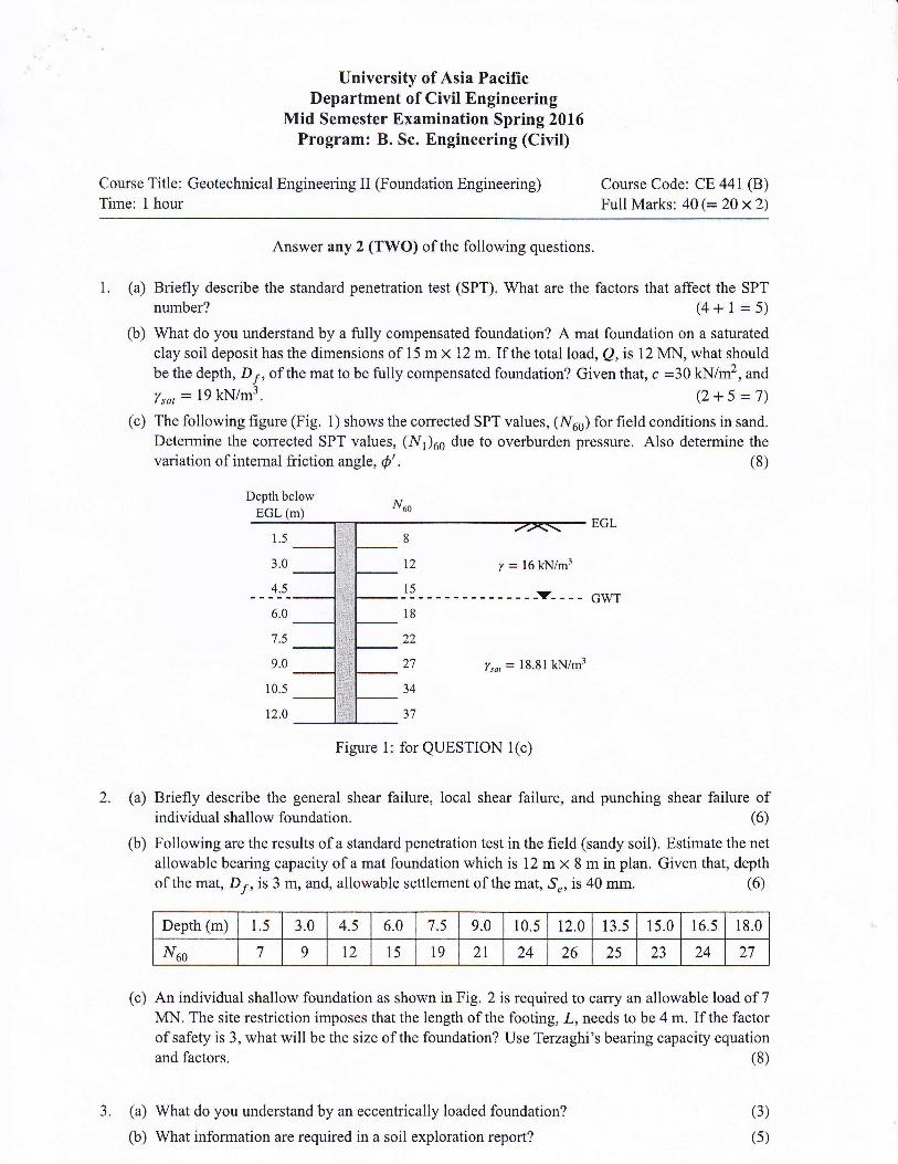
1. (a) Briefly describe the standard penetration test (SPT). What are the factors that affect the SPT number? (4 + 1 = 5)
(b) What do you understand by a fully compensated foundation? A mat foundation on a saturated clay soil deposit has the dimensions of 15 m x 12 m. If the total load, Q, is 12 MN, what should be the depth, D 1 , of the mat to be fully compensated foundation? Given that, c =30 kN/m2
, and
Ysat = 19 kN/m3. (2 + 5 = 7)
(c) The following figure (Fig. 1) shows the corrected SPT values, (N60) for field conditions in sand. Determine the corrected SPT values, (N1) 60 due to overburden pressure. Also determine the variation of internal friction angle, ¢'. (8)
Depth below
EGL (m) ~~ ............. ~.....,.......,.~~~~~~~~.........,,.......-.e-~EGL
1.5
3.0
4.5
6.0
7.5
9.0
10.5
12.0
,____
8
12 y = 16 kN/m3
-1~--------------T ____ GWT
18
22
27
34
37
Ysat = 18. 81 kN/m3
Figure 1: for QUESTION 1 ( c)
2. (a) Briefly describe the general shear failure, local shear failure, and punching shear failure of individual shallow foundation. (6)
(b) Following are the results of a standard penetration test in the field (sandy soil). Estimate the net allowable bearing capacity of a mat foundation which is 12 m x 8 min plan. Given that, depth of the mat, D1, is 3 m, and, allowable settlement of the mat, Se, is 40 mm. (6)
Depth (m) 1.5 3.0 4.5 6.0 7.5 9.0 10.5 12.0 13.5 15.0 16.5 18.0
N6o 7 9 12 15 19 21 24 26 25 23 24 27
( c) An individual shallow foundation as shown in Fig. 2 is required to carry an allowable load of 7 MN. The site restriction imposes that the length of the footing, L , needs to be 4 m. If the factor of safety is 3, what will be the size of the foundation? Use Terzaghi's bearing capacity equation and factors . (8)
3. (a) What do you understand by an eccentrically loaded foundation?
(b) What information are required in a soil exploration report?
(3)
(5)

Qui/ow= 7 MN
EGL~------
c = 20 kN/m2
y = 16 kN/m3 2 m ¢ = 31'
3.5 m __ ,,.. _______ _ GWT
Ysar = 19.81 kN/m3
l.Sm
BxL
Figure 2: for QUESTION 2(c)
(c) For the eccentrically loaded rectangular footing as shown in the following figure (Fig. 3), determine the net allowable bearing capacity assuming a factor of safety of 3. Use Meyerhof's effective area method. (12)
EGL~------.......... c = SO kN/m2 - 4m
y = 17 kN/m3 1.7 m
I ¢ = 34· 3.2m __ ,,.. _________ ,_ '
GWT I
Ysar = 19 kN/m3
1.5 m
3mx4m
(a) Cross-section (b) Plan
Figure 3: for QUESTION 3(c)

Necessary Equations and Tables
3 CN=-
(J'I
2+ _Q Pa
¢' = y20 (N1 ) 60 + 20
Table 1: Terzaghi's bearing capacity factors for general shear failure
<P N , Na Nv 29' 34.24 19.98 17.21 30' 37.16 22.46 19.75 31 ' 40.41 25.28 22.72 32' 44.04 28.52 26.21 33' 48 .09 32.23 30.33
Table 2: Bearing capacity factors for general bearing capacity equation
<P N, Nq N, (Meyerhot)
32' 35.49 23 .18 22.02 33' 38.64 26.09 26.17 34' 42.16 29.44 31.15 35' 46.12 33.30 37.15 36' 50.59 37.75 44.43
Table 3: Shape, depth, and load inclination factors for general bearing capacity equation
Author Factor Condition Equation
<P = o· F,, = 1 + 0.2 ( z)
Shape Fq, = Frs = 1
F,, = 1 + 0.2 (I) tan2
( 45 + ~) </J ~ 10'
Fq, = Fr, = 1 + 0.1 (I) tan2
( 45 + ~)
<P = O' F,a = 1 + 0.2 ( ~ )
Meyerhoff Depth Fqd = Frd = 1
F,d = 1 + 0.2 ( ~ ) tan ( 45 + ~) <P ~ JO'
Fqd = F,d = 1 + 0.1 ( ~ ) tan ( 45 + ~)
any <P ( • 2
F=F= 1-~) Cl q1 90'
Inclination <P > o· F,1 = ( 1- ;: r <P = o· F,1 = 0
N6o ( B + 0.3 )2
(Se) q,,e, = 0.08 B Fd 25
Where,
qnet = net allowable bearing capacity (kN/m2)
Fd = 1 + 0.33 ( 1;: ) s 1.33

University of Asia Pacific Department of Civil Engineering
Mid Semester Examination Spring 2016 Program: B.Sc. Engineering (Civil)
Course Title: Transportation Engi neering II Time: 1 Hour
1. Answer any 5 (5X2 =10)
a. How flexible and rigid pavement differ in load spreading capability?
b. What is Atterberg Limit?
Course Code: CE 451 Full Marks: 20
c. What is the permeability of soil? Characterize loose soil and dense soil in terms of
permeability?
d. For measuring the resistance of aggregates to weathering action, which of test will you
conduct? Which property of aggregate is tested by conducting aggregate impact test?
e. What is well graded bitum inous mix?
f . What is bituminous mix design?
g. What does Marshal l Stability measure?
2. Answer any 1 (1X4 = 4)
a. The results of Marshall test for five specimen is given in Table 1. Find the optimum bitumen
content of the mix. Check the results with the specified test limit given in Table 2 and give
comment.
Table 1: Marshall Test Data
Bitumen Stability Flow Ai r Void Voids Filled with Bulk Specific
Content(%) (kg) (Unit) (%) Bitumen(%) Gravity of Mix
3 499.4 9 12.5 34 2.17
4 717.3 9.6 7.2 65 2.21
5 812.7 12 3.9 84 2.26
6 767.3 14.8 2.4 91 2.23
7 662 .8 19.5 1.9 93 2.18
Table 2: Specified Test Limit
T a bl e 2: Spe c i -f'i e d Tes t L imit

I
University of Asia Pacific Department of Civil Engineering
Mid Semester Examination Spring 2016 Program: B.Sc. Engineering (Civil)
Course Title: Transportation Engineering II Time: 1 Hour
3. Answer any one (lXG = 6)
Course Code: CE 451 Full Marks: 20
a. The gradation required for a typical mix is given in Table 1 in column 1 and 2. The gradation of available for three types of aggregate A, B, and C are given in column 3, 4, and 5. Determine the proportions of A,B and C if mixed will get the required gradation in column 2.
Table 1
Sieve Size (mm) Required Gradation Filler Fine Aggregate Coarse Aggregate Range (A) (B) (C)
25.4 100 100 100 100
12.7 90-100 100 100 94
4.76 60-75 100 100 54
1.18 40-55 100 66.4 31.3
0.3 20-35 100 26 22.8
0.15 12-22 73.6 17.6 9
0.075 5-10 40.1 5 3.1
b. The following results were obta ined by a mechanical sieve analysis. Classify the soil according to the AASHTO classification system and give the group index. State whether this material is suitable in its natural state for use as a subbase material.
Sieve Size % passing by Weight Liquid Limit= 33
No. 4 30 Plastic Limit= 12
No. 40 40
No.200 30
AASTHO Classification of Soils and Soil Aggregate Mixtures
General Classification General Materials (35% or less passing O.Oi5 mm) Silt.clay materials (more than 3 5% passing
O.Oi5 nun) A-1 A·- A·i
Group Clrnification A.1.a A-1-b
A-3 A.2 . .l A·2-5 A-2·6 A-2-i
A..:! A.5 A.6 A.7.5 .A.,.i .6
Sim Analysis % passing 2.00mm(No lO) 50max
0..t2 5 nun (No40) 30m.1x 50ma., 51min 0.725 nun (No200) l 5nu., .5ma., I Onu., 35max 35ma., 35m.1x 35nu., 36min 36min 36min 36min
Characteristics of fraction pmmg 6max
Liquid limit NP .lOma., 41min .lOnu., .llmin 40max .llmin 40ma:< .JOrnin Plastic Index I Onu., !Onm !!min !!min lOmax !Omax llmin !!min
Usual types of significant Stone fragment Fuie Silty or clayey Gmel and sand Constituent material Gral' el and sand Sand Silt\' soils Clavey soils
General rating Excellent to Good Fair to poor