Embed Size (px)
Citation preview
University of Birmingham
Silver-Coated Teflon Tubes for Waveguiding at1–2 THzNavarro-Cia, Miguel; Melzer, Jeffrey E.; Harrington, James A.; Mitrofanov, Oleg
DOI:10.1007/s10762-015-0157-5
License:Creative Commons: Attribution (CC BY)
Document VersionPublisher's PDF, also known as Version of record
Citation for published version (Harvard):Navarro-Cia, M, Melzer, JE, Harrington, JA & Mitrofanov, O 2015, 'Silver-Coated Teflon Tubes for Waveguidingat 1–2 THz', Journal of Infrared, Millimeter, and Terahertz Waves, vol. 36, no. 6, pp. 542-555.https://doi.org/10.1007/s10762-015-0157-5
Link to publication on Research at Birmingham portal
Publisher Rights Statement:Published under a Creative Commons Attribution license
Checked Jan 2016
General rightsUnless a licence is specified above, all rights (including copyright and moral rights) in this document are retained by the authors and/or thecopyright holders. The express permission of the copyright holder must be obtained for any use of this material other than for purposespermitted by law.
•Users may freely distribute the URL that is used to identify this publication.•Users may download and/or print one copy of the publication from the University of Birmingham research portal for the purpose of privatestudy or non-commercial research.•User may use extracts from the document in line with the concept of ‘fair dealing’ under the Copyright, Designs and Patents Act 1988 (?)•Users may not further distribute the material nor use it for the purposes of commercial gain.
Where a licence is displayed above, please note the terms and conditions of the licence govern your use of this document.
When citing, please reference the published version.
Take down policyWhile the University of Birmingham exercises care and attention in making items available there are rare occasions when an item has beenuploaded in error or has been deemed to be commercially or otherwise sensitive.
If you believe that this is the case for this document, please contact [email protected] providing details and we will remove access tothe work immediately and investigate.
Download date: 13. Feb. 2022
1 23
Journal of Infrared, Millimeter, andTerahertz Waves ISSN 1866-6892Volume 36Number 6 J Infrared Milli Terahz Waves (2015)36:542-555DOI 10.1007/s10762-015-0157-5
Silver-Coated Teflon Tubes forWaveguiding at 1–2 THz
Miguel Navarro-Cía, Jeffrey E. Melzer,James A. Harrington & Oleg Mitrofanov
1 23
Your article is published under the Creative
Commons Attribution license which allows
users to read, copy, distribute and make
derivative works, as long as the author of
the original work is cited. You may self-
archive this article on your own website, an
institutional repository or funder’s repository
and make it publicly available immediately.
Silver-Coated Teflon Tubes for Waveguiding at 1–2 THz
Miguel Navarro-Cía1,2,3,4 & Jeffrey E. Melzer5 &
James A. Harrington5 & Oleg Mitrofanov4
Received: 20 February 2015 /Accepted: 19 March 2015 /Published online: 15 April 2015# The Author(s) 2015. This article is published with open access at Springerlink.com
Abstract Realization of single-mode low-loss waveguides for 1.0–2.0 THz remains a chal-lenging problem due to large absorption in most dielectrics and ohmic losses in metals. Toaddress this problem, we investigate dielectric-lined hollow metallic waveguides fabricated bycoating 1-mm diameter 38-μm-thick polytetrafluoroethylene tubes with silver. These wave-guides support a hybrid HE11 mode, which exhibits low attenuation and low dispersion. Quasi-single-mode propagation is achieved in the band of 1.0–1.6 THz, in which the hybrid HE11mode is supported by the waveguide. In this band, the experimentally measured loss is~20 dB/m (~0.046 cm−1), whereas the numerically computed loss is ~7 dB/m(~0.016 cm−1). The difference is attributed to additional losses in the dielectric layer, whichcan be reduced by using alternative polymers.
Keywords Near-field time-domainmicroscopy. Terahertz imaging . Terahertz spectroscopy.
Terahertz waveguide . Ultrafast measurement
1 Introduction
Dielectric-lined hollow metallic waveguides (HMWs) have become a strong candidate foreffective single-mode terahertz (THz) propagation with achievable transmission loss below1 dB/m [1]. They have been investigated and successfully realized for the frequency band of
J Infrared Milli Terahz Waves (2015) 36:542–555DOI 10.1007/s10762-015-0157-5
* Miguel Navarro-Cí[email protected]
1 Optical and Semiconductor Devices Group, Department of Electrical and Electronic Engineering,Imperial College London, London SW7 2AZ, UK
2 Centre for Plasmonics and Metamaterials, Imperial College London, London SW7 2AZ, UK3 Centre for Terahertz Science and Engineering, Imperial College London, London SW7 2AZ, UK4 Department of Electronic and Electrical Engineering, University College London, Torrington Place,
London WC1E 7JE, UK5 School of Engineering, Rutgers University, 607 Taylor Road, Piscataway, NJ 08854, USA
1.5–5.0 THz [1–5], where propagation in free-space [6] or in open waveguides [7, 8] is highlyrestricted due to water vapor absorption [9].
The dielectric-lined HMWs belong to the family of oversized waveguides [10, 11], whichwere developed to solve the problem of increasing ohmic losses of single-mode coaxial andrectangular waveguides at millimeter-wave frequencies. By introducing a dielectric coating onthe inner metallic walls of an oversized waveguide (as a rule of thumb, ~λ0/4 thick), thewaveguide dominant mode becomes the linearly polarized hybrid HE11 mode [1–5, 11–16].This HE11 mode is advantageous because it suffers low losses and it couples efficiently to free-space linearly polarized Gaussian beams [11, 17]. It also can be coupled to the widely usedTE10 mode of the rectangular waveguide using a relatively simple conversion [11].
The attenuation of the HE11 mode falls rapidly with the waveguide diameter [2, 3, 12,18, 19]. The diameter to wavelength ratio (d/λ0) of ~4.4 or larger (assuming a low-loss-dielectric layer) reduces the loss below that of the fundamental TE11 mode of a silver-onlywaveguide [18]. For dielectrics with losses, the required diameter to wavelength ratioincreases.
Despite the oversized waveguide cross-section, the multimode nature is suppressed indielectric-lined HMWs as the other modes, e.g., the TE11, TM11, and TE12 modes, suffer asignificant increase in their attenuation coefficient. This effect is known as self-filtering [11].The dielectric-lined HMWs as a result can enable quasi-single-mode propagation with trans-mission loss potentially lower than that of the fundamental modes in the rectangular wave-guide (TE10) and in the cylindrical metallic waveguide (TE11) with the fractional bandwidthlarger than 50 %.
To realize a polymer-lined HMW with transmission losses <10 dB/m and self-filteringproperties for the 0.5–1.5 THz range, the polymer thickness must be between ~30 and~120 μm and d>0.9 mm. Depositing uniform polymer layers of such thickness remains achallenge for the dynamic liquid phase fabrication technique [20] used for the 1.5–5.0 THzrange. Alternative methods, such as mandrel-winding [5], mechanical-assembling of dielectricand metallic cylinders [11, 13, 14], and high-temperature bonding [21] do not offer a solutionbecause the minimum diameter d for these methods is limited to ~3 mm, which allowsundesirable higher-order modes, and fabrication tolerances are excessive.
Away to circumvent the obstacle of fabricating dielectric-lined HMWs for 0.5 THz<v<1.5THz may be found by metallizing the outer surface of polymer tubes [19], which are cheaplyand easily available in a wide range of thicknesses and diameters. Among the large catalogueof polymer tubes, those made of polytetrafluoroethylene (PTFE), commonly known by itstrade name Teflon, may be good candidates. PTFE was indeed used for the original millimeter-wave dielectric-lined HMWs [11] and it is widely used for many millimeter-wave devicesbecause of its low absorption [22, 23]. Although the absorption of PTFE is not the lowestamong polymers and it increases with frequency, this material can serve to test properties ofthe waveguides fabricated by this method and to establish a benchmark for future investiga-tions with low-loss polymers.
To answer the question whether commercial PTFE tubes are suitable for fabricationof the high-performance dielectric-lined HMW for 0.5 THz<v<1.5 THz band, wecharacterize transmission of THz pulses through PTFE tubes coated with silver exper-imentally. The extracted transmission loss properties are compared with eigenmodesimulations.
PTFE tubes of 1 mm bore diameter and ~38-μm-thick walls are chosen for this study.According to initial analytical work, the fundamental HE11 mode for a waveguide with such
J Infrared Milli Terahz Waves (2015) 36:542–555 543
dimensions (d/λ0~4.4) should have attenuation ~10 dB/m, similar to the fundamental TE11mode of a silver-only waveguide within the transmission band centered at 1.3–1.4 THz. Thesilver-only waveguide with the same diameter however is multimode for the whole spectralwindow studied here.
We fabricate flexible waveguides by coating the PTFE tube with silver. The quasi-single-mode (HE11) propagation is observed after ~283 mm of propagation in the waveguide. We findthe transmission loss of ~20 dB/m within a wide transmission band (~1.0 to ~1.6 THz)experimentally using the cut-back loss method and the THz time-domain spectroscopy system.The numerical simulations show evolution of mode profiles for the supported modes and theirattenuation with frequency, and explain the quasi-single-mode (HE11) propagation. Compar-ison of the experimental and simulation results suggests that dielectric losses in PTFE used inthis study are larger than nominal. Nevertheless, this waveguide concept realized with otherlower-loss dielectric tube can lead to quasi-single-mode waveguides outperforming cylindricalmetallic waveguides of similar diameter.
2 Fabrication and experimental setup
2.1 Fabrication
The silver-coated PTFE hollow waveguide is fabricated with a three-step procedure [19]. First,the outer surface of the 1-mm-bore diameter flexible PTFE tube (Zeus Inc. [24]) is etchedusing a commercial etchant, FluorEtch©, from Acton Technologies. As the surface energy ofPTFE is exceptionally low, this step is necessary to ensure subsequent adhesion of the silverfilm. Second, a palladium-based sensitizing solution is used to further treat the tube surface.Finally, the silver layer is formed via dynamic liquid phase deposition of ammonia-complexedsilver ion and dextrose solutions.
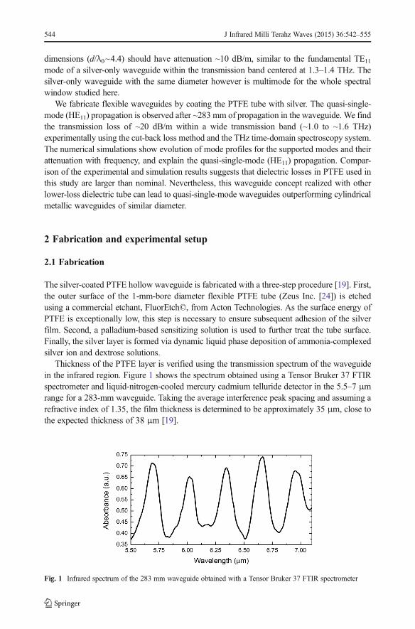
Thickness of the PTFE layer is verified using the transmission spectrum of the waveguidein the infrared region. Figure 1 shows the spectrum obtained using a Tensor Bruker 37 FTIRspectrometer and liquid-nitrogen-cooled mercury cadmium telluride detector in the 5.5–7 μmrange for a 283-mm waveguide. Taking the average interference peak spacing and assuming arefractive index of 1.35, the film thickness is determined to be approximately 35 μm, close tothe expected thickness of 38 μm [19].
Fig. 1 Infrared spectrum of the 283 mm waveguide obtained with a Tensor Bruker 37 FTIR spectrometer
544 J Infrared Milli Terahz Waves (2015) 36:542–555
2.2 Experimental setup
We characterize the waveguide samples using the near-field THz time-domain spectroscopymethod (shown in Section 4). Near-field mapping of the terahertz field at the waveguide outputallows us to optimize coupling from the incident terahertz pulse and determine the spatialmode profiles. The cut-back loss measurement method also avoids potential errors due to thevariation of the coupling coefficient with frequency [4, 25, 26].
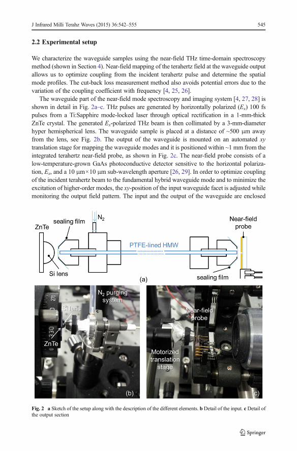
The waveguide part of the near-field mode spectroscopy and imaging system [4, 27, 28] isshown in detail in Fig. 2a–c. THz pulses are generated by horizontally polarized (Ex) 100 fspulses from a Ti:Sapphire mode-locked laser through optical rectification in a 1-mm-thickZnTe crystal. The generated Ex-polarized THz beam is then collimated by a 3-mm-diameterhyper hemispherical lens. The waveguide sample is placed at a distance of ~500 μm awayfrom the lens, see Fig. 2b. The output of the waveguide is mounted on an automated xytranslation stage for mapping the waveguide modes and it is positioned within ~1 mm from theintegrated terahertz near-field probe, as shown in Fig. 2c. The near-field probe consists of alow-temperature-grown GaAs photoconductive detector sensitive to the horizontal polariza-tion, Ex, and a 10 μm×10 μm sub-wavelength aperture [26, 29]. In order to optimize couplingof the incident terahertz beam to the fundamental hybrid waveguide mode and to minimize theexcitation of higher-order modes, the xy-position of the input waveguide facet is adjusted whilemonitoring the output field pattern. The input and the output of the waveguide are enclosed
Fig. 2 a Sketch of the setup along with the description of the different elements. b Detail of the input. c Detail ofthe output section
J Infrared Milli Terahz Waves (2015) 36:542–555 545
into sealed holders and purged with N2 to reduce water vapor absorption inside the waveguide(see Fig. 2a, b for the N2 inlet, and Fig. 2a, c for the output holder).
3 Numerical modeling
We first review the eigenmodes supported by the PTFE-lined HMW to provide a basis for theanalysis of the experimental results.
3.1 Transmission losses and field distribution inside the waveguide
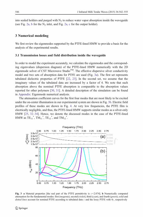
In order to model the experiment accurately, we calculate the eigenmodes and the correspond-ing eigenvalues (dispersion diagram) of the PTFE-lined HMW numerically with the 2Deigenmode solver of CST Microwave StudioTM. The effective dispersive silver conductivitymodel and two sets of absorption data for PTFE are used (Fig. 3a). The first set representstabulated dielectric properties of PTFE [22, 23]. In the second set, we assume that theimaginary values of the tabulated data are increased by a factor of 4. We note that suchabsorption above the nominal PTFE absorption is comparable to the absorption valuesreported for other polymers [30, 31]. A detailed description of the simulation can be foundin Appendix: Eigenmode numerical analysis.
The attenuation coefficient curves for the first four modes that are most likely to be excitedunder the on-center illumination in our experimental system are shown in Fig. 3b. Electric fieldprofiles of these modes are shown in Fig. 4. At very low frequencies, the PTFE film iselectrically negligible, and thus, the PTFE-lined HMW supports similar modes as a silver-onlyHMW [25, 32–34]. Hence, we denote the discussed modes in the case of the PTFE-linedHMW as TE11
*, TM11*, TE12
*, and TM12*.
Fig. 3 a Material properties [the real part of the PTFE permittivity is ε=2.074]. b Numerically computedattenuation for the fundamental modes: first (magenta), second (violet), third (cyan), and fourth (green); solid anddotted lines account for nominal PTFE according to tabulated data ε and the lossy PTFE with 4ε, respectively
546 J Infrared Milli Terahz Waves (2015) 36:542–555
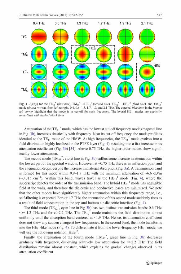
Attenuation of the TE11* mode, which has the lowest cut-off frequency mode (magenta line
in Fig. 3b), increases drastically with frequency. Near its cut-off frequency, the mode profile isidentical to the TE11 mode of the HMW. At high frequencies, the TE11
* mode evolves into afield distribution highly localized in the PTFE layer (Fig. 4), resulting into a fast increase in itsattenuation coefficient (Fig. 3b) [34]. Above 0.75 THz, the higher-order modes show signif-icantly lower attenuation.
The second mode (TM11*, violet line in Fig. 3b) suffers some increase in attenuation within
the lowest part of the spectral window. However, at ~0.75 THz there is an inflection point andthe attenuation drops, despite the increase in material absorption (Fig. 3a). A transmission bandis formed for this mode within 0.9–1.7 THz with the minimum attenuation of ~6.6 dB/m(~0.015 cm−1). Within this band, waves travel as the HE11
1 mode (Fig. 4), where thesuperscript denotes the order of the transmission band. The hybrid HE11
1 mode has negligiblefield at the walls, and therefore the dielectric and conductive losses are minimized. We notethat the other modes have significantly higher attenuation within this frequency range, i.e.,self-filtering is expected. For ν>1.7 THz, the attenuation of this second mode suddenly rises asa result of field concentration in the top and bottom air-dielectric interface (Fig. 4).
The third mode (TE12*, cyan line in Fig 3b) has two distinct transmission bands: 0.6 THz
<ν<1.2 THz and for ν>2.2 THz. The TE12* mode maintains the field distribution almost
uniformly until the absorption band centered at ~1.9 THz. Hence, its attenuation coefficientdoes not show any sudden change at low frequencies. In the second band, the mode transformsinto the HE11-like mode (Fig. 4). To differentiate it from the lower-frequency HE11 mode, wewill use the following notation: HE11
2.Finally, the attenuation of the fourth mode (TM12
*, green line in Fig. 3b) decreasesgradually with frequency, displaying relatively low attenuation for ν>2.2 THz. The fielddistribution remains almost constant, which explains the gradual changes observed in itsattenuation coefficient.
Fig. 4 Ex(x,y) for the TE11* (first row), TM11
*→HE111 (second row), TE12
*→HE112 (third row), and TM12
*
mode (fourth row) at, from left to right, 0.4, 0.6, 1.3, 1.7, 1.9, and 2.1 THz. The external blue lines in the bottomleft corner highlight that the mode is in cut-off for such frequency. The hybrid HE11 modes are explicitlyunderlined with dashed black lines
J Infrared Milli Terahz Waves (2015) 36:542–555 547
For both hybrid HE11 modes, the transmission bands become narrower and the attenuationincreases when higher dielectric losses are considered in the modeling [4, 18]. Specifically, theHE11
1 mode transmission band is limited between 1.0 and 1.6 THz with a minimum attenu-ation of ~16.2 dB/m (~0.037 cm−1).
3.2 Impact of bending and metal model in transmission losses
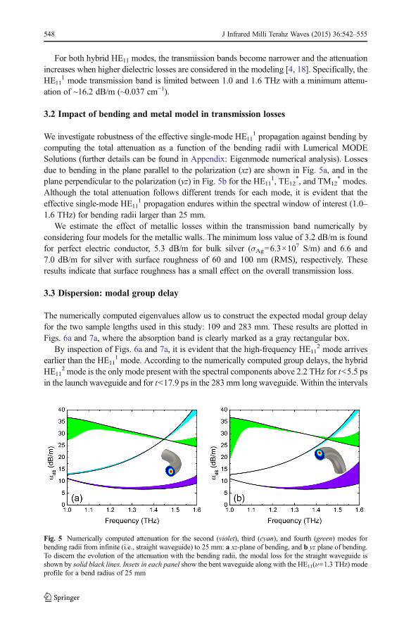
We investigate robustness of the effective single-mode HE111 propagation against bending by
computing the total attenuation as a function of the bending radii with Lumerical MODESolutions (further details can be found in Appendix: Eigenmode numerical analysis). Lossesdue to bending in the plane parallel to the polarization (xz) are shown in Fig. 5a, and in theplane perpendicular to the polarization (yz) in Fig. 5b for the HE11
1, TE12*, and TM12
* modes.Although the total attenuation follows different trends for each mode, it is evident that theeffective single-mode HE11
1 propagation endures within the spectral window of interest (1.0–1.6 THz) for bending radii larger than 25 mm.
We estimate the effect of metallic losses within the transmission band numerically byconsidering four models for the metallic walls. The minimum loss value of 3.2 dB/m is foundfor perfect electric conductor, 5.3 dB/m for bulk silver (σAg=6.3×10
7 S/m) and 6.6 and7.0 dB/m for silver with surface roughness of 60 and 100 nm (RMS), respectively. Theseresults indicate that surface roughness has a small effect on the overall transmission loss.
3.3 Dispersion: modal group delay
The numerically computed eigenvalues allow us to construct the expected modal group delayfor the two sample lengths used in this study: 109 and 283 mm. These results are plotted inFigs. 6a and 7a, where the absorption band is clearly marked as a gray rectangular box.
By inspection of Figs. 6a and 7a, it is evident that the high-frequency HE112 mode arrives
earlier than the HE111 mode. According to the numerically computed group delays, the hybrid
HE112 mode is the only mode present with the spectral components above 2.2 THz for t<5.5 ps
in the launch waveguide and for t<17.9 ps in the 283 mm long waveguide. Within the intervals
Fig. 5 Numerically computed attenuation for the second (violet), third (cyan), and fourth (green) modes forbending radii from infinite (i.e., straight waveguide) to 25 mm: a xz-plane of bending, and b yz plane of bending.To discern the evolution of the attenuation with the bending radii, the modal loss for the straight waveguide isshown by solid black lines. Insets in each panel show the bent waveguide along with the HE11(ν=1.3 THz) modeprofile for a bend radius of 25 mm
548 J Infrared Milli Terahz Waves (2015) 36:542–555
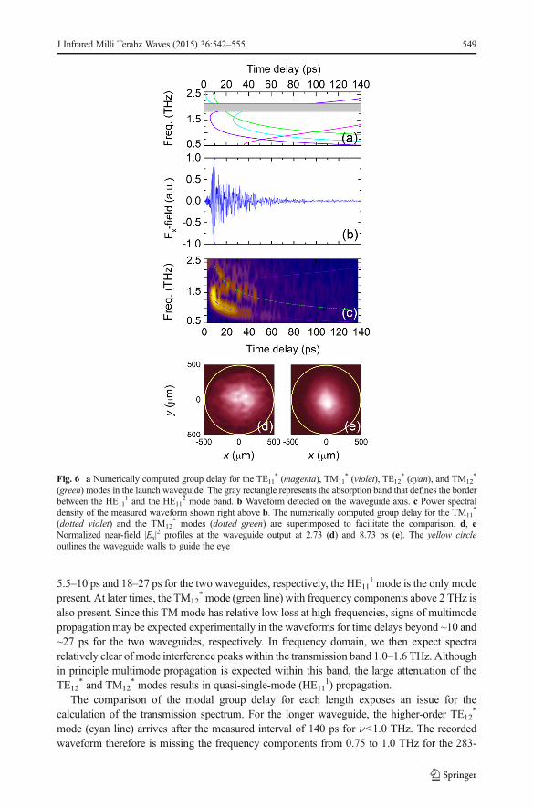
5.5–10 ps and 18–27 ps for the two waveguides, respectively, the HE111 mode is the only mode
present. At later times, the TM12* mode (green line) with frequency components above 2 THz is
also present. Since this TMmode has relative low loss at high frequencies, signs of multimodepropagation may be expected experimentally in the waveforms for time delays beyond ~10 and~27 ps for the two waveguides, respectively. In frequency domain, we then expect spectrarelatively clear of mode interference peaks within the transmission band 1.0–1.6 THz. Althoughin principle multimode propagation is expected within this band, the large attenuation of theTE12
* and TM12* modes results in quasi-single-mode (HE11
1) propagation.The comparison of the modal group delay for each length exposes an issue for the
calculation of the transmission spectrum. For the longer waveguide, the higher-order TE12*
mode (cyan line) arrives after the measured interval of 140 ps for ν<1.0 THz. The recordedwaveform therefore is missing the frequency components from 0.75 to 1.0 THz for the 283-
Fig. 6 a Numerically computed group delay for the TE11* (magenta), TM11
* (violet), TE12* (cyan), and TM12
*
(green) modes in the launch waveguide. The gray rectangle represents the absorption band that defines the borderbetween the HE11
1 and the HE112 mode band. b Waveform detected on the waveguide axis. c Power spectral
density of the measured waveform shown right above b. The numerically computed group delay for the TM11*
(dotted violet) and the TM12* modes (dotted green) are superimposed to facilitate the comparison. d, e
Normalized near-field |Ex|2 profiles at the waveguide output at 2.73 (d) and 8.73 ps (e). The yellow circle
outlines the waveguide walls to guide the eye
J Infrared Milli Terahz Waves (2015) 36:542–555 549
mm-long waveguide. If the input terahertz beam is coupled initially to the TM11* mode and the
TE12* mode, the calculation of the transmission spectrum overestimates losses within the
0.75–1.0 THz frequency span. Indeed, excitation of both modes is likely at low frequenciessince both modes have similar overlap integrals with the Gaussian beam. A similar argument isapplied to ν<0.75 THz, for the TE11
* and TM12* modes. Therefore, for ν<1.0 THz, the
experimentally measured losses can only provide an upper bound.
4 Near-field time-domain measurements and discussion
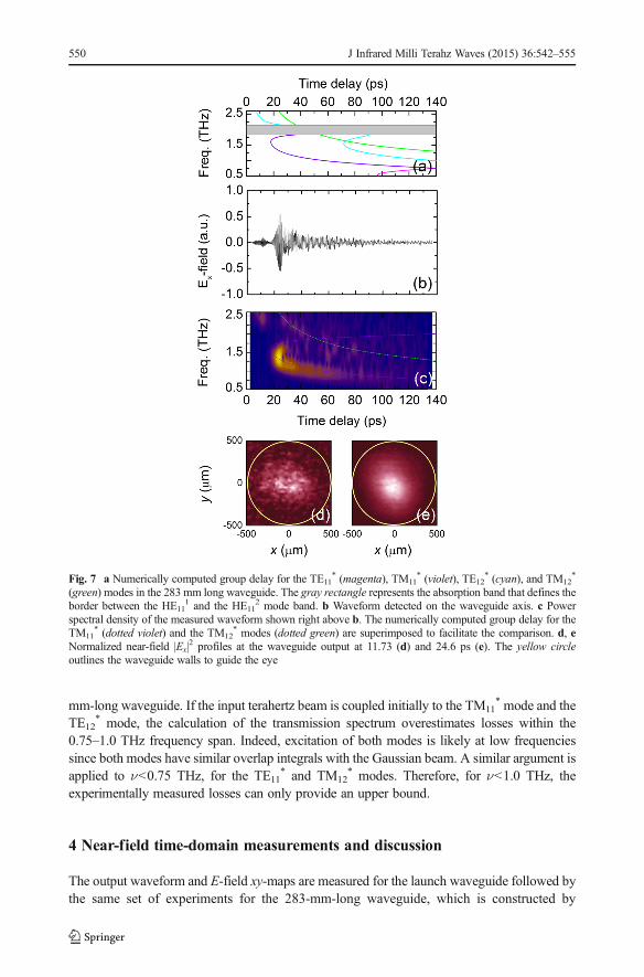
The output waveform and E-field xy-maps are measured for the launch waveguide followed bythe same set of experiments for the 283-mm-long waveguide, which is constructed by
Fig. 7 a Numerically computed group delay for the TE11* (magenta), TM11
* (violet), TE12* (cyan), and TM12
*
(green) modes in the 283 mm long waveguide. The gray rectangle represents the absorption band that defines theborder between the HE11
1 and the HE112 mode band. b Waveform detected on the waveguide axis. c Power
spectral density of the measured waveform shown right above b. The numerically computed group delay for theTM11
* (dotted violet) and the TM12* modes (dotted green) are superimposed to facilitate the comparison. d, e
Normalized near-field |Ex|2 profiles at the waveguide output at 11.73 (d) and 24.6 ps (e). The yellow circle
outlines the waveguide walls to guide the eye
550 J Infrared Milli Terahz Waves (2015) 36:542–555
attaching an additional segment of 174 mm to the launch waveguide. This approach allows usto determine the transmission loss produced by the 174-mm segment.
The waveforms detected in the center of the waveguide output for the launch and joinedsamples are shown in Figs. 6b and 7b, respectively. Two pulses can be resolved in bothwaveforms. Using the modeling results, we could tentatively assign them to the HE11
2 andHE11
1 modes. Indeed, the intensity xy-map at the peaks of the leading and second transmittedpulses reveals HE11 mode profile for both pulses (Figs. 5d, e and 6d, e), confirming theassumption.
Signs of multimode interference are also noticeable for the second pulse. Namely, thecoherent oscillations in the pulse are interrupted at ~10 and ~27 ps for the launch and 283-mm-long waveguide, respectively. This is also in agreement with the numerical results.
The mode interference can be observed in the spectrograms, i.e., time-frequency-maps,computed for each waveform (Figs. 6c and 7c). The waveform is divided into 28 Hamming-windowed segments with 90 % overlap. At earlier time delays, only the spectral component ataround 2.4 THz, which is linked to the HE11
2 mode, is observed. The strongest signal is at 1.1–1.6 THz in both spectrograms. The HE11
1 mode is expected in this range. Low dispersion canbe seen near the band center. The lack of signal around 1.9 THz is linked to the absorptionband.
In both spectrograms, the HE111 mode (violet line) forms a tail due to large dispersion for v
<1.1 THz, when it changes to the TM11* mode. The TM12
* mode (green line) also yieldsanother tail for 1.3 THz<v<2.5 THz. For the 283-mm-long waveguide, the trace associated tothe TM12
* mode is almost absent, suggesting that quasi-single HE11 mode propagation isobtained after 283 mm within the HE11
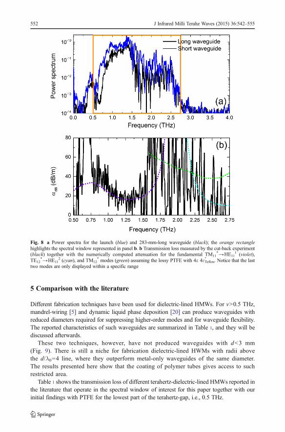
1 transmission band.The waveguide transmission spectrum is calculated by taking the ratio of the power spectra
(Fig. 8a). Figure 8b presents the attenuation in decibels per meter, αdB. A signal-to-noise ratioabove 10 is achieved within a frequency span from 0.5 to 2.75 THz (spectral windowhighlighted by the orange box in Fig. 8a). This spectral region includes the fundamentaltransmission band, the absorption band and the low frequency part of the second transmissionband [4, 5, 19, 32–34].
In the transmission band, 1.0 THz<ν<1.6 THz, where the hybrid mode HE11 is fullydeveloped, losses decrease to ~17 dB/m (~0.039 cm−1) at approximately 1.3 THz. To put thisvalue of attenuation in context, it is worth looking at commercial single-mode hollowwaveguides. For instance, the rectangular waveguide WR-0.65 used by Virginia Diodes Inc.to cover the bandwidth 1.1–1.7 THz (similar to the transmission band here) has an estimatedwaveguide loss between 258 and 406 dB/m at the low and high end of the band, respectively[35], which is hundreds of decibels higher than our experimentally reported waveguide loss.The experimental spectrum is consistent with the prediction that the transmission loss isminimal for this waveguide at ~1–2 THz. The spectrum quantitatively matches the transmis-sion band from the simulation with dielectric absorption larger than the nominal used before(i.e., 4εTeflon
″ ). The rapid oscillations in this band over the baseline are caused by multimodepropagation involving the dominant HE11
1 and the TM12* modes.
The more pronounced rapid oscillations observed for ν>1.6 THz in both waveformspectra (Fig. 8a) as well as in the transmission spectrum (Fig. 8b) suggest multimodepropagation, but with a less defined dominant mode. In this range, the HE11 and TM12
*
modes travel with similar attenuation (see Fig. 8b), and thus, there is not a distinctdominant mode producing a clear baseline. This is in agreement with the spectrogramsand the modeling.
J Infrared Milli Terahz Waves (2015) 36:542–555 551
5 Comparison with the literature
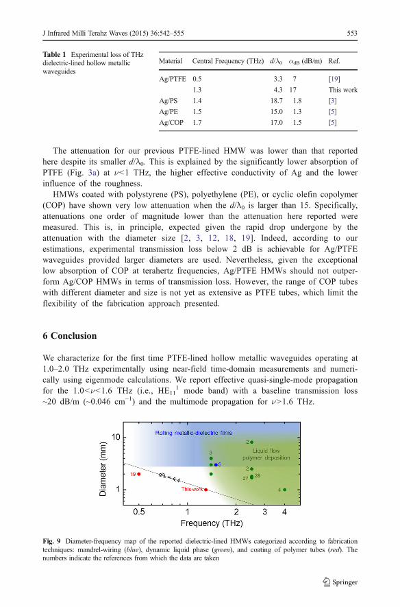
Different fabrication techniques have been used for dielectric-lined HMWs. For v>0.5 THz,mandrel-wiring [5] and dynamic liquid phase deposition [20] can produce waveguides withreduced diameters required for suppressing higher-order modes and for waveguide flexibility.The reported characteristics of such waveguides are summarized in Table 1, and they will bediscussed afterwards.
These two techniques, however, have not produced waveguides with d<3 mm(Fig. 9). There is still a niche for fabrication dielectric-lined HWMs with radii abovethe d/λ0=4 line, where they outperform metal-only waveguides of the same diameter.The results presented here show that the coating of polymer tubes gives access to suchrestricted area.
Table 1 shows the transmission loss of different terahertz-dielectric-lined HMWs reported inthe literature that operate in the spectral window of interest for this paper together with ourinitial findings with PTFE for the lowest part of the terahertz-gap, i.e., 0.5 THz.
Fig. 8 a Power spectra for the launch (blue) and 283-mm-long waveguide (black); the orange rectanglehighlights the spectral window represented in panel b. b Transmission loss measured by the cut-back experiment(black) together with the numerically computed attenuation for the fundamental TM11
*→HE111 (violet),
TE12*→HE11
2 (cyan), and TM12* modes (green) assuming the lossy PTFE with 4ε 4εTeflon
″ . Notice that the lasttwo modes are only displayed within a specific range
552 J Infrared Milli Terahz Waves (2015) 36:542–555
The attenuation for our previous PTFE-lined HMW was lower than that reportedhere despite its smaller d/λ0. This is explained by the significantly lower absorption ofPTFE (Fig. 3a) at ν<1 THz, the higher effective conductivity of Ag and the lowerinfluence of the roughness.
HMWs coated with polystyrene (PS), polyethylene (PE), or cyclic olefin copolymer(COP) have shown very low attenuation when the d/λ0 is larger than 15. Specifically,attenuations one order of magnitude lower than the attenuation here reported weremeasured. This is, in principle, expected given the rapid drop undergone by theattenuation with the diameter size [2, 3, 12, 18, 19]. Indeed, according to ourestimations, experimental transmission loss below 2 dB is achievable for Ag/PTFEwaveguides provided larger diameters are used. Nevertheless, given the exceptionallow absorption of COP at terahertz frequencies, Ag/PTFE HMWs should not outper-form Ag/COP HMWs in terms of transmission loss. However, the range of COP tubeswith different diameter and size is not yet as extensive as PTFE tubes, which limit theflexibility of the fabrication approach presented.
6 Conclusion
We characterize for the first time PTFE-lined hollow metallic waveguides operating at1.0–2.0 THz experimentally using near-field time-domain measurements and numeri-cally using eigenmode calculations. We report effective quasi-single-mode propagationfor the 1.0<ν<1.6 THz (i.e., HE11
1 mode band) with a baseline transmission loss~20 dB/m (~0.046 cm−1) and the multimode propagation for ν>1.6 THz.
Table 1 Experimental loss of THzdielectric-lined hollow metallicwaveguides
Material Central Frequency (THz) d/λ0 αdB (dB/m) Ref.
Ag/PTFE 0.5 3.3 7 [19]
1.3 4.3 17 This work
Ag/PS 1.4 18.7 1.8 [3]
Ag/PE 1.5 15.0 1.3 [5]
Ag/COP 1.7 17.0 1.5 [5]
Fig. 9 Diameter-frequency map of the reported dielectric-lined HMWs categorized according to fabricationtechniques: mandrel-wiring (blue), dynamic liquid phase (green), and coating of polymer tubes (red). Thenumbers indicate the references from which the data are taken
J Infrared Milli Terahz Waves (2015) 36:542–555 553
The fabrication approach employed here to produce a quasi-single-mode dielectric-linedhollow waveguide holds promise for the 1.0–2.0 THz range owing to its simplicity (coatingcommercially available tubes) and because the use of alternative fabrication techniquesremains elusive. The proposed approach is universal and can be applied to any other polymerprovided the suitable etching agent is used such that a silver film can be effectively deposited.Therefore, it is necessary to investigate other polymers with known lower absorption values inthe region of interest such as COP.
Acknowledgments This work was supported in part by the Engineering and Physical Sciences ResearchCouncil (grant numbers EP/G033870/1 and EP/J017671/1), and the Royal Society (grant numberUF080745). The work of M. Navarro-Cía was supported by Imperial College London through a JuniorResearch Fellowship.
Conflict of Interest The authors declare that they have no conflict of interest.
Appendix
Eigenmode numerical analysisThe transmission properties of the Ag-coated PTFE tube are modeled with CST
Microwave StudioTM using a two-dimensional frequency-domain eigenmode analysis [4,19, 25]. To simplify the calculation, the thickness of the silver film is considered semi-infinite (i.e., the background material outside the PTFE tube is silver). Given that the Agfilm thickness is much larger than the skin depth within the spectral region of interest,this simplification does not have any effect in the waveguide modes. An effectivedispersive conductivity calculated via the Hammerstad-Jensen approach that takes intoaccount the roughness of the metal is used to model the background material silver. Weassume that the roughness of the metal is equal to the measured average RMS roughnessof the PTFE outer surface after the etching procedure, but before the deposition of thesilver film: 60 nm. The simulated geometry consists then of a 38-μm-thick PTFE tube of1 mm diameter loss-free air core. The dielectric property of the PTFE is based ontabulated experimental data [22, 23]. Four times higher dielectric losses are also studiedto account for potential fabrication issues and to show the effect of this parameter in theloss spectrum. Given the twofold symmetry of the problem, a vertical electric and ahorizontal magnetic mirror planes are applied to consider only a quarter of the waveguidecross-section. An adaptive tetrahedral discretization with maximum edge length of 10 μmwithin the PTFE tube is used to match accurately the circular cross-sectional area of thewaveguide.
To study the attenuation due to bending, the commercial software LumericalMODE Solutions is used in this case. The same material properties as for CSTMicrowave StudioTM (nominal PTFE and effective dispersive conductivity for RMSroughness 60 nm) are used. Twofold symmetry is no longer valid, and thus, onlyvertical electric or horizontal magnetic mirror planes are used for the yz- or xz-planeof bending case, respectively. A hexahedral mesh 1.3 μm×1.3 μm is applied in thiscase. The additional bending loss between the straight waveguide and the waveguidewith bending radius R=50 mm computed with the Lumerical MODE Solutions isadded to the attenuation loss of the straight waveguide calculated with CST Micro-wave StudioTM to generate Fig. 5a, b.
554 J Infrared Milli Terahz Waves (2015) 36:542–555
Open Access This article is distributed under the terms of the Creative Commons Attribution 4.0 InternationalLicense (http://creativecommons.org/licenses/by/4.0/), which permits unrestricted use, distribution, and repro-duction in any medium, provided you give appropriate credit to the original author(s) and the source, provide alink to the Creative Commons license, and indicate if changes were made.
References
1. O. Mitrofanov, R. James, F. Aníbal Fernández, T. K. Mavrogordatos, J.A. Harrington, IEEE Trans. THz Sci.Tech. 1, 124 (2011)
2. B. Bowden, J. A. Harrington, O. Mitrofanov, Appl. Phys. Lett. 93, 181104-1-3 (2008)3. P. Doradla, C. S. Joseph, J. Kumar, R. H. Giles, Opt. Express 20, 19176 (2012)4. M. Navarro-Cía, M.S. Vitiello, C.M. Bledt, J.E. Melzer, J.A. Harrington, O. Mitrofanov, Opt. Express 21,
23748 (2013)5. Y. Matsuura, E. Takeda, J. Opt. Soc. Am. B 25, 1949 (2008)6. Y. Yang, M. Mandehgar, D. R. Grischkowsky, IEEE Trans. THz Sci. Tech. 2, 406 (2012)7. R. Mendis, D. M. Mittleman, Opt. Express 17, 14839 (2009)8. T.-I. Jeon, D. Grischkowsky, Appl. Phys. Lett. 88, 06113 (2006)9. Y. Yang, M. Mandehgar, D. Grischkowsky, IEEE T. THz Sci, Tech. 1, 264 (2011)10. S. E. Miller, A. C. Beck, Proc. IRE 41, 348 (1953)11. A.A. Kostenko, A.I. Nosich, P. F. Goldsmith, in History of Wireless, ed. By T. K. Sarkar, R. Mailloux, A. A.
Oliner, M. Salazar-Palma, D. L. Sengupta (Wiley, Hoboken, New Jersey, 2006), ch. 15, pp. 473–54212. E.A.J. Marcatili, R.A. Schmeltzer, Bell Syst. Tech. J. 43, 1783 (1964)13. L. N. Vershinina, Y. N. Kasantsev, V. V. Meriakri,V. V. Shevchenko, in 1st European Microwave Conference,
London, UK, 1969, p 25114. A.I. Goroshko, Y.M. Kuleshov, Radiotekhnika 21, 215 (1972)15. J.W. Carlin, P. D'Agostino, Bell Syst. Tech. J. 52, 453 (1973)16. J.W. Carlin, A. Maione, Bell Syst. Tech. J. 52, 487 (1973)17. R. K. Nubling, J. A. Harrington, Opt. Eng. 37, 2454 (1998)18. X.-L. Tang, Y.-W. Shi, Y. Matsuura, K. Iwai, M. Miyagi, Opt. Lett. 34, 2231 (2009)19. J. E. Melzer, M. Navarro-Cía, O. Mitrofanov, J. A. Harrington, Proc. SPIE 8938, 89380I (2014)20. J. A. Harrington, Infrared fiber optics and their applications, 1st edn. (SPIE, Bellingham, Washington, 2004)21. R.J. Boyd, W.E. Cohen, W.P. Doran, R.D. Tuminaro, The Bell Syst. Tech. J. 56,1873 (1997)22. C. Winnerwisser, F. Lewen, H. Helm, Appl. Phys. A 66, 593 (1998)23. J. Kawamura, S. Paine, and D.C. Papa, in Proceedings of the Seventh International Symposium on Space
Terahertz Technology, (National Radio Astronomy Observatory, 1996), p. 349.24. http://www.zeusinc.com/25. M. Navarro-Cía, C. M. Bledt, M. S. Vitiello, H. E. Beere, D. A. Ritchie, J. A. Harrington, O. Mitrofanov, J.
Opt. Soc. Am. B 30, 127 (2013)26. R. Mueckstein, M. Navarro-Cía, O. Mitrofanov, Appl. Phys. Lett. 102, 141103 (2013)27. O. Mitrofanov, T. Tan, P. R. Mark, B. Bowden, J. A. Harrington, Appl. Phys. Lett. 94, 171104 (2009)28. O. Mitrofanov, J. A. Harrington, Opt. Express 18, 1898 (2010)29. O. Mitrofanov, M. Lee, J.W.P. Hsu, I. Brener, R. Harel, J.F. Federici, J.D. Wynn, L.N. Pfeiffer, K. W. West,
IEEE J. Sel. Top. Quantum Elect. 7, 600 (2001)30. Y.-S. Jin, G.-J. Kim, S.-G. Jeon, J. Korean Phys. Soc. 49, 513 (2006)31. P. D. Cunningham, N. N. Valdes, F. A. Vallejo, L. M. Hayden, B. Polishak, X.-H. Zhou, J. Luo, A. K.-Y. Jen,
J. C. Williams, R. J. Twieg, J. Appl. Phys. 109, 043505 (2011)32. Y. Kato, M. Miyagi, IEEE Trans. Microw. Theor. Tech. 40, 679 (1992)33. M. Miyagi, S. Kawakami, J. Lightwave Tech. LT-2, 116 (1984)34. Y. Kato, M. Miyagi, IEEE Trans. Microw. Theor. Tech. 42, 2336 (1994)35. http://vadiodes.com/VDI/pdf/waveguidechart200908.pdf
J Infrared Milli Terahz Waves (2015) 36:542–555 555
![Thrombogenicity of Teflon Versus Copolymer-Coated Guidewires · coated guidewires. Thrombogenicity of angiographic guidewires [1-8] and catheters [9-17] has been a concern of angiographers](https://img.pdfslide.net/doc/110x75/5f09392f7e708231d425cf29/thrombogenicity-of-teflon-versus-copolymer-coated-coated-guidewires-thrombogenicity.jpg)