Embed Size (px)
Citation preview
UNIVERSITY OF CINCINNATI DATE: 05/20/2003
I, Balaji Sethuramasamyraja ,
hereby submit this as part of the requirements for the degree of: Master of Science
in: Industrial Engineering
It is entitled: GPS based waypoint navigation for an Autonomous guided vehicle - Bearcat III
Approved by: Dr. Ernest L. Hall Dr. Richard L. Shell Dr. Ronald L. Houston
GPS based waypoint navigation for an autonomous guided vehicle - Bearcat III
A thesis submitted to the
Division of Research and Advanced Studies of the University of Cincinnati
in partial fulfillment of the requirements for the degree of
MASTER OF SCIENCE
in the Department of Mechanical, Industrial and Nuclear
Engineering of the College of Engineering
2003
by
Balaji Sethura masamyraja
B.E (Mechanical Engineering) University of Madras, India, 1999
Committee Chair: Dr. Ernest L. Hall
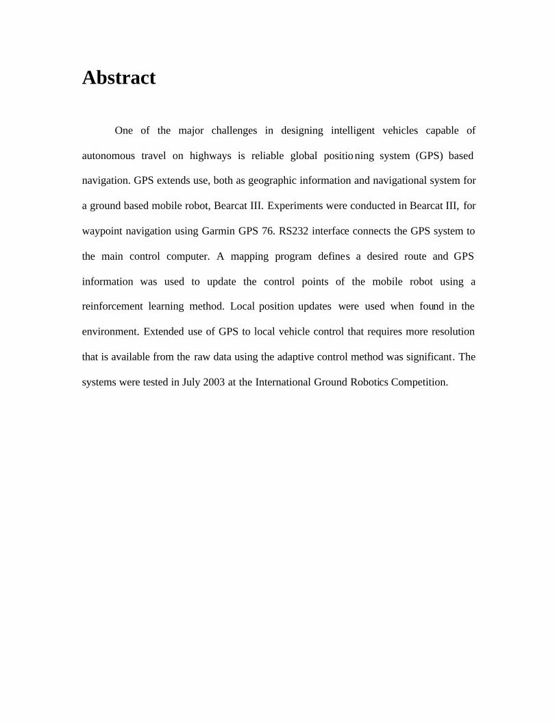
Abstract
One of the major challenges in designing intelligent vehicles capable of
autonomous travel on highways is reliable global positioning system (GPS) based
navigation. GPS extends use, both as geographic information and navigational system for
a ground based mobile robot, Bearcat III. Experiments were conducted in Bearcat III, for
waypoint navigation using Garmin GPS 76. RS232 interface connects the GPS system to
the main control computer. A mapping program defines a desired route and GPS
information was used to update the control points of the mobile robot using a
reinforcement learning method. Local position updates were used when found in the
environment. Extended use of GPS to local vehicle control that requires more resolution
that is available from the raw data using the adaptive control method was significant. The
systems were tested in July 2003 at the International Ground Robotics Competition.
Acknowledgments
I would like to thank my advisor Dr. Ernest L. Hall whose guidance and support
made this thesis possible. His suggestions and guidance helped a lot in my thesis. He
encouraged me in all counters to complete this work.
I would like to thank Dr. Richard L. Shell and Dr. Ronald L. Huston for agreeing
to serve on the committee. I would also like to thank them for their valuable insights and
positive feedbacks.
I would like to thank the Robotics Team members for all the help and support
they had given me during my graduate period of study at the University of Cincinnati. I
would like to thank all my friends and well-wishers who had helped me from time to
time.
Also, I would like to thank my family for their encouragement and support in all
my endeavors. I owe all my success to them.
1
Table of Contents Page Number 1. Introduction 4
1.1 Motivation 4
1.2 Organization of the Thesis 4
2. The Bearcat III 6
2.1 System Design of Bearcat III 6
2.2 Vision System 6
2.3 Motion Control System 8
2.4 Sonar System 9
2.5 Laser Scanner System 10
2.6 Waypoint Navigation Using Global Positioning System 11
2.7 Mechanical System 11
2.8 Power System 12
2.9 Health Monitoring System 13
2.10 Safety System 14
2.10.1 Manual Emergency Stop 14
2.10.2 Remote Controlled Emergency Stop 14
2
3. Literature Review 15
3.1 International Ground Vehicle Competition - Challenge 15
3.2 Research Goals 17
3.3 Global Positioning System Technology 17
3.4 GPS Theory and Accuracy 20
3.5 Navigation Challenge 22
4. The Global Positioning Systems on Bearcat – III 25
4.1 Approach 25
4.2 Selection of a commercial GPS system 25
4.3 Algorithm 27
4.4 Implementation 28
4.5 Experimental Test setup and Results 30
5. Conclusion and Directions for Future Research 32
6. References 34
3
List of Tables and Figures
Page Number Chapter 1
Table 1.1 Performance Characteristics of the Bearcat – III 5
Chapter 2
Figure 2.1 Basic block diagram of Bearcat - III 6
Figure 2.2 Motion control system block diagram 8
Figure 2.3 Sonar obstacle detection systems 9
Figure 2.4 Laser scanner and range detection 10
Figure 2.5 Mechanical system 12
Chapter 3
Figure 3.1 Obstacle course for Bearcat -III 16
Figure 3.2 Determination of Position from four time coded signals 18
Figure 3.3 GPS Constellation 21
Figure 3.4 Typical course for Navigational challenge 23
Chapter 4
Table 4.1 Specifications of Garmin GPS 76 used in Bearcat – III 26
Figure 4.2 Garmin GPS 76 27
Picture 4.3 Team with III Prize in Navigational Challenge in IGVC 2003 31
Picture 4.4 Action during Navigational Challenge in IGVC 2003 31
4
Chapter 1 Introduction 1.1 Motivation
There has been a great amount of research devoted to the global positioning
system based navigation for mobile robot platforms and intelligent vehicles. Any mobile
robot that must reliably operate in an unknown or dynamic environment must be able to
perform intelligent navigation. As road following and off road systems have become
capable, more attention has been focused on GPS based navigation. The Center for
Robotics Research at the University of Cincinnati has built an unmanned, autonomous
guided vehicle named Bearcat III for the Annual Intelligent Ground Vehicles
Competition conducted each year by the Association for Unmanned Vehicle Systems.
1.2 Organization of the Thesis
This thesis is organized into 5 chapters. Chapter 1 is an introduction and gives the
motivation and organization of the thesis. Chapter 2 describes the Bearcat-III systems
Design on which testing was done. Chapter 3 lights the literature overview of
international ground vehicle competition – challenge, research goals, global positioning
system, GPS mechanisms and navigational challenge problem. Chapter 4 describes the
navigational solution approach, algorithm, implementation and test results. Chapter 5
presents the conclusion and directions for future research.
5
Chapter 2 The Bearcat III
Bearcat III is an Autonomous Guided Vehicle built at the University of
Cincinnati, Center for Robotics Research basically for competing in Annual intelligent
ground vehicle competition. It is capable of following line tracks and avoiding obstacles
on the path as prescribed by competition regulations. It does have navigational
capabilities using a global positioning system (GPS). The performance characteristics of
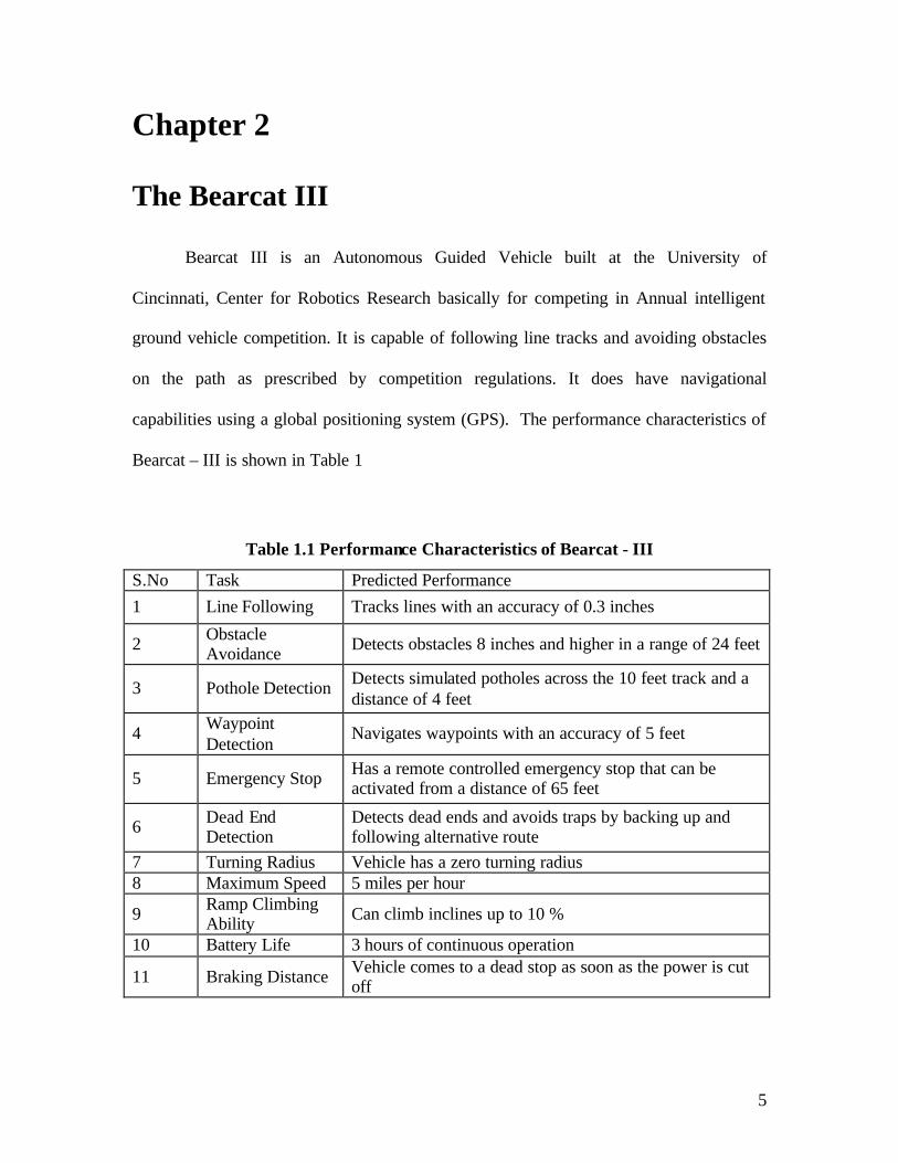
Bearcat – III is shown in Table 1
Table 1.1 Performance Characteristics of Bearcat - III
S.No Task Predicted Performance 1 Line Following Tracks lines with an accuracy of 0.3 inches
2 Obstacle Avoidance Detects obstacles 8 inches and higher in a range of 24 feet
3 Pothole Detection Detects simulated potholes across the 10 feet track and a distance of 4 feet
4 Waypoint Detection
Navigates waypoints with an accuracy of 5 feet
5 Emergency Stop Has a remote controlled emergency stop that can be activated from a distance of 65 feet
6 Dead End Detection
Detects dead ends and avoids traps by backing up and following alternative route
7 Turning Radius Vehicle has a zero turning radius 8 Maximum Speed 5 miles per hour
9 Ramp Climbing Ability Can climb inclines up to 10 %
10 Battery Life 3 hours of continuous operation
11 Braking Distance Vehicle comes to a dead stop as soon as the power is cut off
6
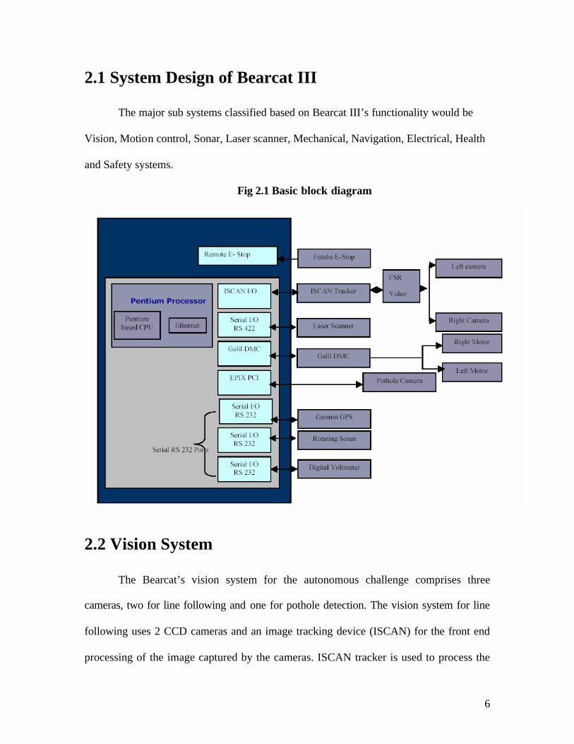
2.1 System Design of Bearcat III
The major sub systems classified based on Bearcat III’s functionality would be
Vision, Motion control, Sonar, Laser scanner, Mechanical, Navigation, Electrical, Health
and Safety systems.
Fig 2.1 Basic block diagram
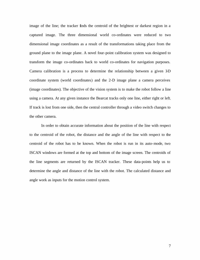
2.2 Vision System
The Bearcat’s vision system for the autonomous challenge comprises three
cameras, two for line following and one for pothole detection. The vision system for line
following uses 2 CCD cameras and an image tracking device (ISCAN) for the front end
processing of the image captured by the cameras. ISCAN tracker is used to process the
7
image of the line; the tracker finds the centroid of the brightest or darkest region in a
captured image. The three dimensional world co-ordinates were reduced to two
dimensional image coordinates as a result of the transformations taking place from the
ground plane to the image plane. A novel four-point calibration system was designed to
transform the image co-ordinates back to world co-ordinates for navigation purposes.
Camera calibration is a process to determine the relationship between a given 3-D
coordinate system (world coordinates) and the 2-D image plane a camera perceives
(image coordinates). The objective of the vision system is to make the robot follow a line
using a camera. At any given instance the Bearcat tracks only one line, either right or left.
If track is lost from one side, then the central controller through a video switch changes to
the other camera.
In order to obtain accurate information about the position of the line with respect
to the centroid of the robot, the distance and the angle of the line with respect to the
centroid of the robot has to be known. When the robot is run in its auto-mode, two
ISCAN windows are formed at the top and bottom of the image screen. The centroids of
the line segments are returned by the ISCAN tracker. These data-points help us to
determine the angle and distance of the line with the robot. The calculated distance and
angle work as inputs for the motion control system.
8
2.3 Motion Control System
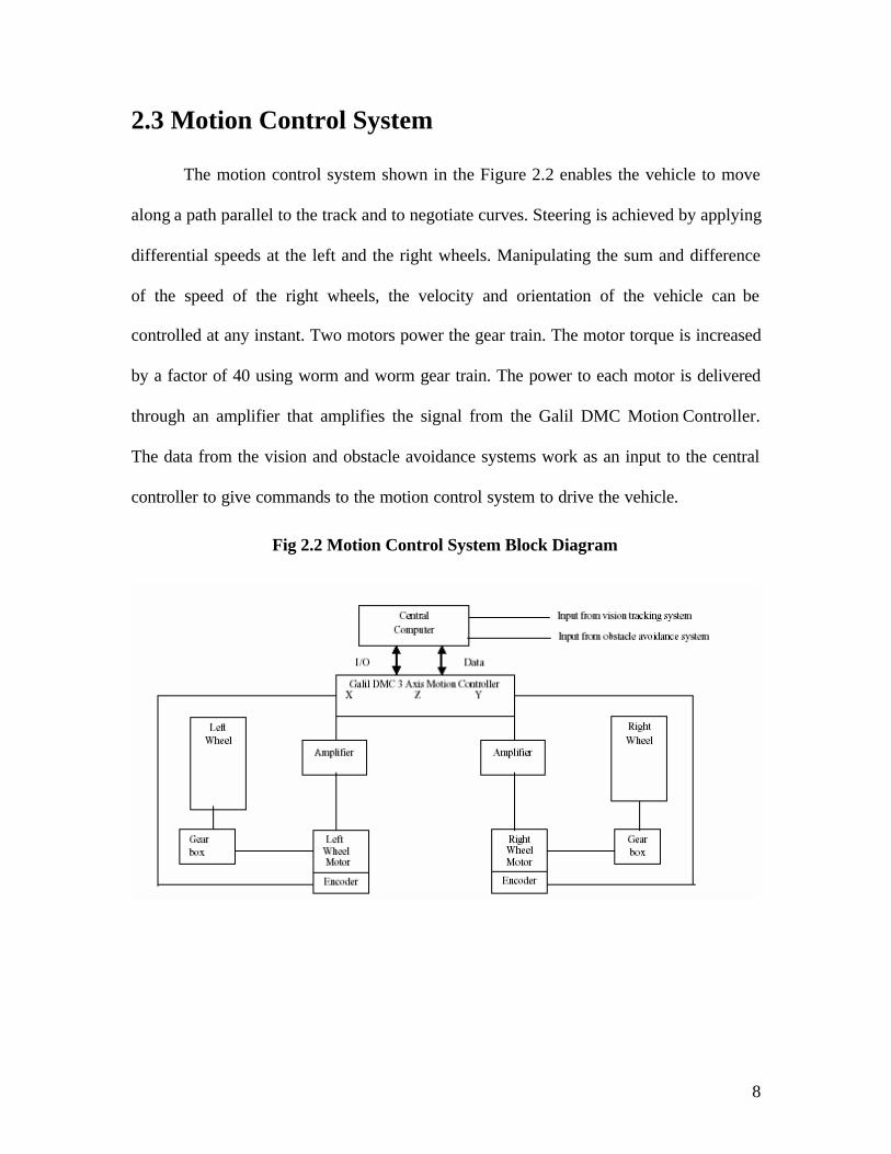
The motion control system shown in the Figure 2.2 enables the vehicle to move
along a path parallel to the track and to negotiate curves. Steering is achieved by applying
differential speeds at the left and the right wheels. Manipulating the sum and difference
of the speed of the right wheels, the velocity and orientation of the vehicle can be
controlled at any instant. Two motors power the gear train. The motor torque is increased
by a factor of 40 using worm and worm gear train. The power to each motor is delivered
through an amplifier that amplifies the signal from the Galil DMC Motion Controller.
The data from the vision and obstacle avoidance systems work as an input to the central
controller to give commands to the motion control system to drive the vehicle.
Fig 2.2 Motion Control System Block Diagram
9
2.4 Sonar System
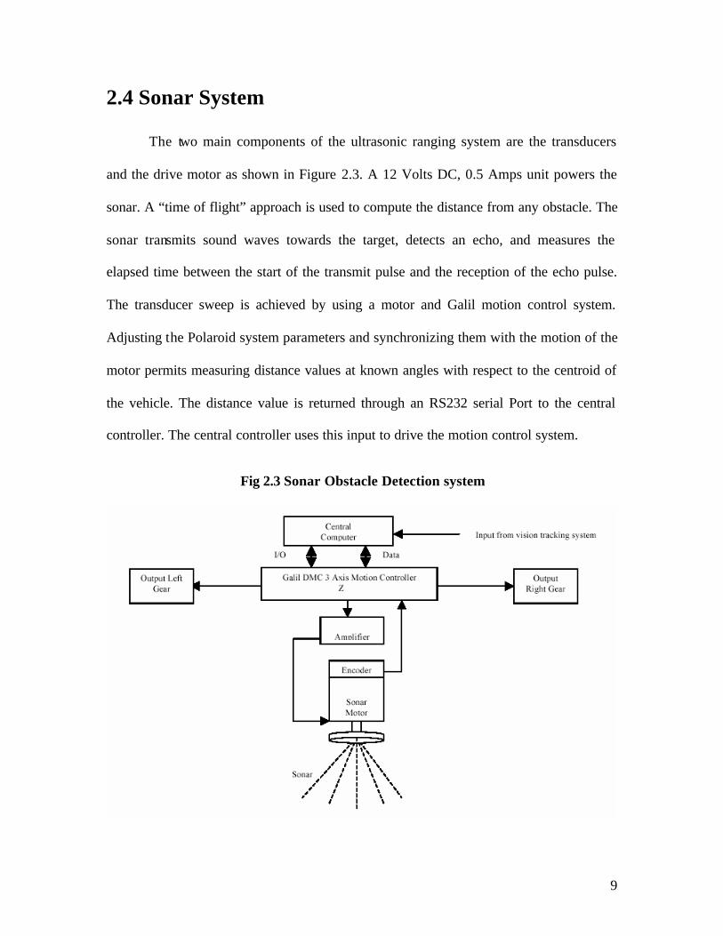
The two main components of the ultrasonic ranging system are the transducers
and the drive motor as shown in Figure 2.3. A 12 Volts DC, 0.5 Amps unit powers the
sonar. A “time of flight” approach is used to compute the distance from any obstacle. The
sonar transmits sound waves towards the target, detects an echo, and measures the
elapsed time between the start of the transmit pulse and the reception of the echo pulse.
The transducer sweep is achieved by using a motor and Galil motion control system.
Adjusting the Polaroid system parameters and synchronizing them with the motion of the
motor permits measuring distance values at known angles with respect to the centroid of
the vehicle. The distance value is returned through an RS232 serial Port to the central
controller. The central controller uses this input to drive the motion control system.
Fig 2.3 Sonar Obstacle Detection system
10
2.5 Laser Scanner System
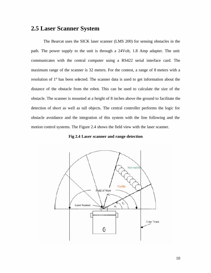
The Bearcat uses the SICK laser scanner (LMS 200) for sensing obstacles in the
path. The power supply to the unit is through a 24Volt, 1.8 Amp adapter. The unit
communicates with the central computer using a RS422 serial interface card. The
maximum range of the scanner is 32 meters. For the contest, a range of 8 meters with a
resolution of 1° has been selected. The scanner data is used to get information about the
distance of the obstacle from the robot. This can be used to calculate the size of the
obstacle. The scanner is mounted at a height of 8 inches above the ground to facilitate the
detection of short as well as tall objects. The central controller performs the logic for
obstacle avoidance and the integration of this system with the line following and the
motion control systems. The Figure 2.4 shows the field view with the laser scanner.
Fig 2.4 Laser scanner and range detection
11
2.6 Waypoint Navigation Using GPS
The methodology behind the Bearcat navigational challenge problem was to
select a commercially available GPS unit and utilize the built in features of the unit to
provide a solution to the GPS navigational problem. This approach relies on the GPS
unit’s navigational processing features and reduces the computational load that the robot
CPU must perform to navigate the course. The basic criteria used in the selection of the
GPS unit are WAAS (Wide Area Augmentation System) capability, RS-232 serial port
input/output ability, external antenna, external power capability, and embedded
navigation features. Based on these selection criteria the Garmin GPS 76 was chosen as
the unit to provide GPS navigational ability to the robot. The major navigational features
of the GPS unit used in the solution of the GPS navigational problem are the ability to
input/output NMEA (National Marine Electronics Association) messages, set target
waypoints, and calculate bearing/range information to the target waypoint. The physical
implementation of GPS navigation feedback control loop consists of the Garmin 76 GPS
unit, the robot motion control system, laser scanner, and the robot computer.
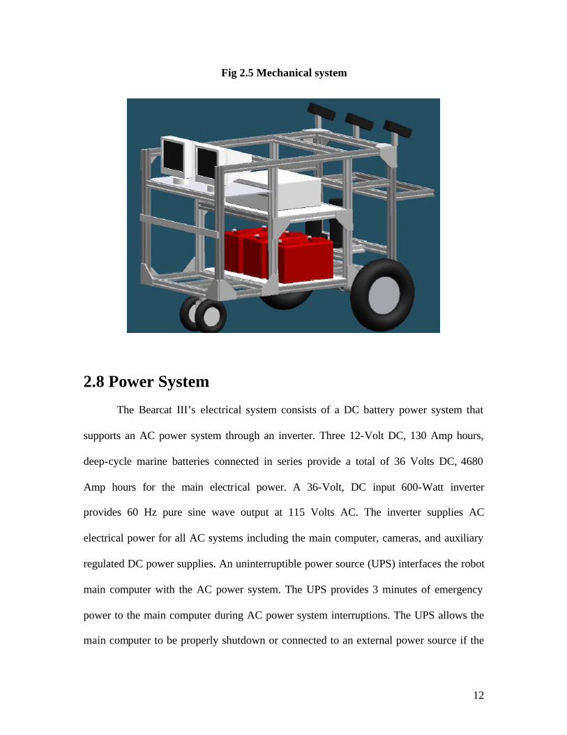
2.7 Mechanical System
The Bearcat III is designed to be an outdoor vehicle able to carry a payload of 100
pounds. Optimal design was arrived using good design practices during basic design and
CAD software such as AutoCAD R14 and IDEAS Master series 7.0 were used in the
final analysis phase for stress and load analysis. The basic structure goes with the
aluminum extrusions, joining plates and T-nuts. The frame is designed with an extruded
aluminum structure to hold the components of the vehicle.
12
Fig 2.5 Mechanical system
2.8 Power System
The Bearcat III’s electrical system consists of a DC battery power system that
supports an AC power system through an inverter. Three 12-Volt DC, 130 Amp hours,
deep-cycle marine batteries connected in series provide a total of 36 Volts DC, 4680
Amp hours for the main electrical power. A 36-Volt, DC input 600-Watt inverter
provides 60 Hz pure sine wave output at 115 Volts AC. The inverter supplies AC
electrical power for all AC systems including the main computer, cameras, and auxiliary
regulated DC power supplies. An uninterruptible power source (UPS) interfaces the robot
main computer with the AC power system. The UPS provides 3 minutes of emergency
power to the main computer during AC power system interruptions. The UPS allows the
main computer to be properly shutdown or connected to an external power source if the
13
main robot AC power system is offline. The DC system provides 36 volts unregulated
DC electrical power to the motors at a maximum of 10 Amps. The total power required
by the Bearcat is approximately 735 Watts for the DC systems and 411.3 Watts for the
AC systems. Thus, 1146-Watts total power is required to operate the Bearcat III. A loss
of 10 percent was estimated for the required power to yield 1261 Watts actually required.
A 10 percent loss can also be assumed for power supplied by the batteries to yield 4212
watt hours available. Based on these estimates the Bearcat III power system has an
estimated endurance of 3.34 hours at full load.
2.9 Health Monitoring System
The Bearcat III is equipped with a self- health monitoring system. A RS 232 serial
port is used to take input from a digital multi-meter, which can be accessed from C++
code to check the total DC voltage of the batteries. The health monitoring is implemented
as a C++ class module that has methods that can monitor battery voltage and display
warning messages to the computer screen. Two voltage threshold trip points can be set
that will trigger a low voltage and a critical low voltage warning message. The low
voltage warning indicates that the battery voltage is below the first threshold trip point
and that preparations should be made to change or charge the batteries. The critical low
voltage warning indicates that corrective actions must be taken immediately because
robot power system shutdown is eminent. The voltmeter class can also be used in code to
sound an audible alarm or activate the robot strobe light at the specified threshold point.
The power system voltage display is visible to the operator and provides a constant
indication of voltage.
14
2.10 Safety System 2.10.1 Manual Emergency Stop
The manual emergency stop unit consists of a red manual push button located on
the easily accessible rear surface of the vehicle. When pressed, the power to the motors is
cut off and the self- locking mechanism of the gearbox brings the vehicle to an instant
halt. The self- locking mechanism ensures that the vehicle does not move when it is not
powered and serves as a safety measure against any undesirable motion such as rolling
when parked on a slope.
2.10.2 Remote Controlled Emergency Stop
The mobile robot can be de-activated by a remote unit from a distance of 65 feet
in compliance with the rules for autonomous challenge of the international ground
vehicle contest. The remote controlled emergency stop consists of a Futaba transmitter, a
receiver, an amplifier, and a relay. The advantage of using this is that the transmitter need
not be in line with the sight of the receiver. The Futaba transmitter uses a 6V DC and
transmits FM signals at 72.470 MHz over a range of 65 feet. This amplified current
activates the contacts of the relay that in turn activates the emergency stop solenoid and
cuts power to the motors.
15
Chapter 3 Literature Review 3.1 International Ground Vehicle Competition - Challenge
An autonomous vehicle needs a sophisticated system for analyzing the failures,
storing the related information in an integrated repository and retrieving the same via
standard user- friendly interface. The Center for Robotics Research at University of
Cincinnati has been developing robots for the past 15 years. The Bearcat robot of UC
Robotics team has undergone three major modifications till now. The latest version called
Bearcat III. The Center for Robotics Research at the University of Cincinnati has been a
participant in the Annual Intelligent Vehicles Competition competition for the last 10
years. The University of Cincinnati has so far used three versions of their Automated
Guided Vehicles.
The competition requires a fully autonomous ground robotic vehicle to negotiate
around an outdoor obstacle course under a prescribed time while staying within the 5
mph speed limit and avoiding the obstacles on the laid track. Unmanned, autonomous
vehicles must compete based on their ability to perceive the course environment and
avoid obstacles without human assistance in any form during competition. All
computational, power, sensing and control equipment must be carried on board the
vehicle. The course is out on grass, pavement, simulated pavement, or any combination,
over an area of approximately 60 to 80 yards long, by 40 to 60 yards wide. The path of
vehicle travel is marked by solid white lines (which can be dashed at certain regions).
16
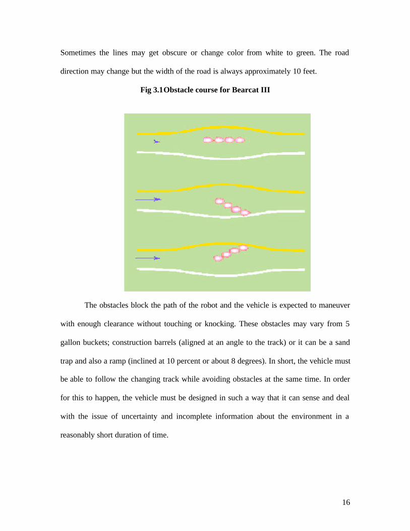
Sometimes the lines may get obscure or change color from white to green. The road
direction may change but the width of the road is always approximately 10 feet.
Fig 3.1Obstacle course for Bearcat III
The obstacles block the path of the robot and the vehicle is expected to maneuver
with enough clearance without touching or knocking. These obstacles may vary from 5
gallon buckets; construction barrels (aligned at an angle to the track) or it can be a sand
trap and also a ramp (inclined at 10 percent or about 8 degrees). In short, the vehicle must
be able to follow the changing track while avoiding obstacles at the same time. In order
for this to happen, the vehicle must be designed in such a way that it can sense and deal
with the issue of uncertainty and incomplete information about the environment in a
reasonably short duration of time.
17
3.2 Research Goals
The ability to navigate in known and unknown environments belongs to the key
skills of today's mobile robots. Especially in structured environments, characteristics of
the robot's surroundings can be used to simplify the task. The University of Cincinnati
Robotics Research Center has been working on improving the ability of the automated
guided vehicles for several years. Each year, some new features are added to extend the
robot functionalities. Navigation and positioning are crucial to mobile robot navigation
and yet the process has always been quite cumbersome. Over the years the Cincinnati
Robotics team has successfully developed vision systems and sonar sensors on their robot
Bearcat III to trace landmarks so that the vehicle could understand where it is. However,
this is highly unreliable as it is worked only in local area and also subject to movement or
destruction by environmental factors. The quest for greater and greater navigation
accuracy has spawned the idea of employing GPS technology to improve the robot
navigation functionality. The goal of this research was to implement Garmin GPS 76 on
Bearcat III for waypoint navigation in its environment.
3.3 Global Positioning System Technology
Global Positioning Systems (GPS) provide navigational community with
powerful tools for acquiring accurate and current digital data. Combined with high
resolution remote sensing and GIS for land use studies, GPS can provide high accuracy
data for navigation.
The Global Positioning System is a satellite-based radio navigation system
initially developed and operated by the U.S. Department of Defense (DOD). In 1996, a
18
Presidential Decision Directive, later passed into law, transferred "ownership" from DOD
to an Interagency GPS Executive Board (IGEB), co-chaired by senior officials of the
Departments of Transportation and Defense to provide management oversight to assure
that GPS meets civil and military user requirements. GPS permits land, sea, and airborne
users to determine their three-dimensional position, velocity, and time 24 hours a day, in
all weather, anywhere in the world with a precision and accuracy far better than other
radio navigation systems available today or in the foreseeable future. GPS consists of
three segments: space, control, and user.
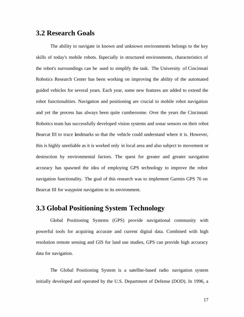
Fig 3.2 Determination of coordinates from four coded time signals
The Space segment consists of 24 operational satellites in six 12-hour orbits
20,200 km (10,900 ml) above the earth at an inclination angle of 55 degrees. The
satellites are spaced in orbit so that at any time a minimum of 4 satellites will be in view
to users anywhere in the world. The satellites continuously broadcast a low power, one
19
way position and time signal to users throughout the world. There are currently 29
satellites in orbit, or five spares, which assure the availability of 24 operational satellites.
The Control Segment consists of a master control station in Colorado Springs,
Colorado, with five monitor stations and three control up-link stations located throughout
the world. Monitor stations track all GPS satellites in view and collect ranging
information from the satellite broadcasts. This information is then sent back to the master
control station, which computes extremely precise satellite orbits. The data is then
formatted into updated navigation messages for each satellite. The updated information is
transmitted to each satellite via the control up- link stations, which also transmit and
receive satellite control and monitoring signals.
The User Segment consists of the receivers, processors, and antennas that allow
land, sea, or airborne operators to receive the GPS satellite broadcasts and compute their
precise position, velocity and time. GPS, formally known as the Navstar Global
Positioning System, was initiated in 1973 to reduce the proliferation of navigation aids.
By creating a system that overcame the limitations of many existing navigation systems,
GPS became attractive to a broad spectrum of users.
GPS has been successful in virtually all navigation applications, and because its
capabilities are accessible using small, inexpensive equipment, GPS is also being used in
many new market applications today. There are five stations around the world (Hawaii,
Ascension Island, Diego Garcia, Kwajalein, and Colorado Springs.) monitoring the GPS
satellites, checking both their operational functions and their exact position in pace. The
ground station transmits corrections for the satellite's ephemeris constants and clock
20
offsets back to the satellites. The satellites can then incorporate these updates in the
signals they send to the surface of the earth and can be read by GPS receivers. It
functions just like assigning each patch of land a unique address. GPS satellites provide
specially coded signals that can be processed in a GPS receiver, enabling the receiver to
compute altitude, longitude, height, velocity and time. Precise positioning could be
achieved by using GPS receivers at different locations providing corrections and
reference positioning data for remote receivers.
Time and frequency dissemination, based on the precise clocks on board the
satellites and controlled by the monitor stations, is another use for GPS. Astronomical
observatories, telecommunications facilities, and laboratory standards can be set to
precise time signals or controlled to accurate frequencies by special purpose GPS
receivers. Research projects also use GPS signals to weight atmospheric parameters.
Generally, at least four satellite signals should be read to determine precisely of one
position on earth. The determination of position and time from satellites is shown in
Figure 3.2. Determination of coordinates from four coded time signals.
3.4 GPS Theory and Accuracy
GPS receivers collect signals from satellites in view. They display the user's
position, velocity, and time, as needed for their marine, terrestrial, or aeronautical
applications. Some display additional data, such as distance and bearing to selected
waypoints or digital charts. The GPS concept of operation is based upon satellite ranging.
Users determine their position by measuring their distance from the group of satellites in
21
space. The satellites act as precise reference points. Each GPS satellite transmits an
accurate position and time signal. The user's receiver measures the time delay for the
signal to reach the receiver, which is the direct measure of the apparent range (called a
"pseudo range”), to the satellite. Measurements collected simultaneously from four
satellites are processed to solve for the three dimensions of position (latitude, longitude,
and altitude) and time. Position measurements are in the worldwide WGS-84 geodetic
reference system, and time is with respect to a worldwide common U.S. Naval
Observatory Time (USNO) reference.
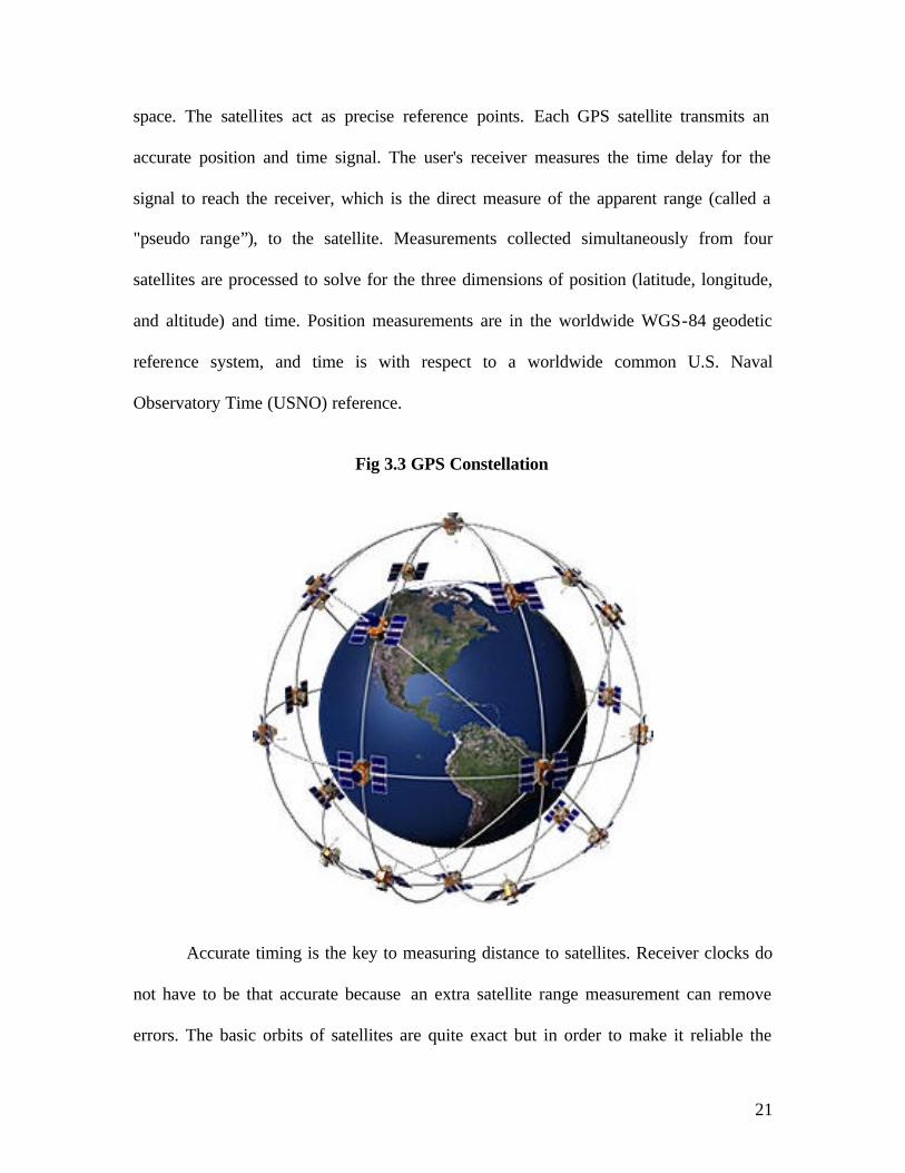
Fig 3.3 GPS Constellation
Accurate timing is the key to measuring distance to satellites. Receiver clocks do
not have to be that accurate because an extra satellite range measurement can remove
errors. The basic orbits of satellites are quite exact but in order to make it reliable the
22
GPS satellites are constantly monitored by the Department of Defense (DoD). They use
precise radar to check each satellite's exact altitude, position and speed. The errors they're
checking are called "ephemeris errors" because they affect the satellite's orbit or
"ephemeris." These errors are generated by gravitational pulls from the moon and sun and
by the pressure of solar radiation on the satellites. The errors are usually very slight but if
you want high level accuracy they must be taken into account. Once the DoD has
measured a satellite's precise position, they relay that information back up to the satellite
itself. The satellite then includes this new corrected position information in the timing
signals it is broadcasting. So a GPS signal is more than just pseudo-random code for
timing purposes. It also contains a navigation message with ephemeris information as
well. The ionosphere and atmosphere around the earth cause delays in the GPS signal that
translate into position errors. Some errors can be factored out with mathematics and
modeling. The configuration of the satellites in the sky can magnify other errors.
Differential GPS can eliminate almost all errors.
3.5 Navigation Challenge
The challenge in this event is for a vehicle to autonomously travel from a starting
point to a number of target destinations (waypoints or landmarks) and return to home
base, given only a map showing the coordinates of those targets. Coordinates of the
targets will be given in latitude and longitude as well as in meters on an x-y grid. The
contestants are expected to use Differential GPS, but non-differential GPS is allowed as
well as dead reckoning with compasses, gyros, and wheel odometers. WAAS or any of
the commercial suppliers of corrections are also allowed.
23
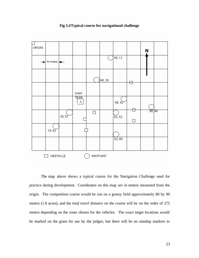
Fig 3.4Typical course for navigational challenge
The map above shows a typical course for the Navigation Challenge used for
practice during development. Coordinates on this map are in meters measured from the
origin. The competition course would be run on a grassy field approximately 80 by 90
meters (1.8 acres), and the total travel distance on the course will be on the order of 275
meters depending on the route chosen for the vehicles. The exact target locations would
be marked on the grass for use by the judges, but there will be no standup markers to
24
indicate those positions. Construction barrels and certain other obstacles would be located
on the course in such positions that they must be circumvented to reach the waypoints.
The robot is supposed to navigate to each successive target point based on GPS
satellite position data and arrival at a target point is defined as approaching within five
feet of the target point. The GPS is used to get the original position, then tracking is used
to move the robot from one point to the next, updating the new base with every pass. The
GPS receiver outputs position (latitude, longitude, height) and velocity information at a
rate of 1 second per output to 255 seconds per output. The accuracy of the output varies
between 5 feet to 25 feet. The normal robot speed is about 5 feet /second, and the motion
command delay is about 0.5 second.
The main issue in controlling with GPS feedback is to maximize the accuracy. In
order to do this, several sample data should be accumulated and then the average and
variance computed through a least squares method. Also, since the contest field has
limited distance, errors due to the earth arc may be ignored. However, when the robot is
in motion, the sampling historical data are taken not for a fixed spot. This could be fixed
by adding shifts of the robot over time to the historical data, which could then be
processed as if they are sampled at the same spot over a period of time.
25
Chapter 4 The Global Positioning System on Bearcat III 4.1 Approach
The approach is basically to choose commercially available GPS units which with
its navigational processing features eliminate the need for computation in the main
computer that can be conserved for obstacle avoidance and line following features during
the contest. This method also eliminates the need for GPS navigational algorithms
development as they are already loaded by GPS unit manufacturer in the kit. The GPS
unit selected was also based on the criteria that its embedded software be upgradeable as
newer versions become available from the manufacturer.
4.2 Selection of Commercial GPS system
A commercially available GPS unit was selected and it’s built in features are
utilized to provide a solution to the GPS navigational problem. The primary reason for
selection of the Garmin GPS 76 unit is Waas capability to improve the accuracy, RS-232
serial port input/output ability for ease of interfacing, and embedded navigational features
which avoid fresh development. Waas capability improves the accuracy of the standard
GPS signals to 3 meters which can be inferred from the table 4.1 Specifications of
Garmin GPS 76 used in Bearcat - III. The RS-232 input/output capability allows the
robot computer to interface with the GPS unit directly and process the navigational data
from the GPS unit.
26
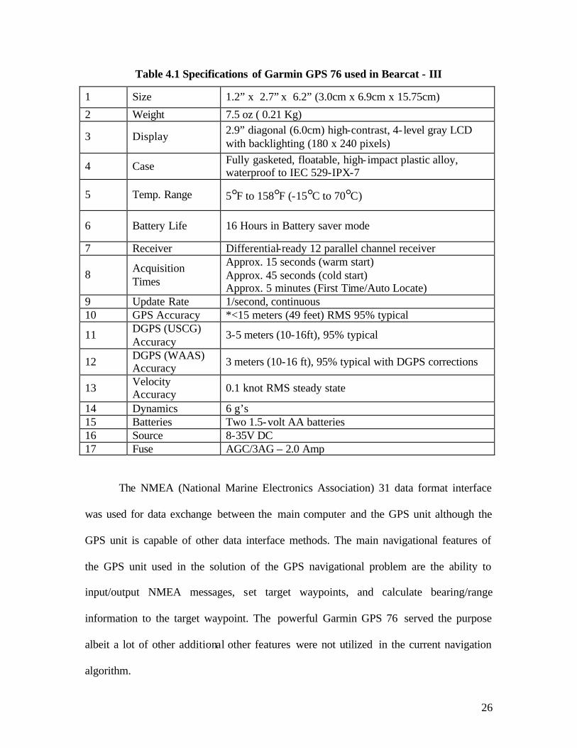
Table 4.1 Specifications of Garmin GPS 76 used in Bearcat - III
1 Size 1.2” x 2.7” x 6.2” (3.0cm x 6.9cm x 15.75cm)
2 Weight 7.5 oz ( 0.21 Kg)
3 Display 2.9” diagonal (6.0cm) high-contrast, 4- level gray LCD with backlighting (180 x 240 pixels)
4 Case Fully gasketed, floatable, high- impact plastic alloy, waterproof to IEC 529-IPX-7
5 Temp. Range 5°F to 158°F (-15°C to 70°C)
6 Battery Life 16 Hours in Battery saver mode
7 Receiver Differential-ready 12 parallel channel receiver
8 Acquisition Times
Approx. 15 seconds (warm start) Approx. 45 seconds (cold start) Approx. 5 minutes (First Time/Auto Locate)
9 Update Rate 1/second, continuous 10 GPS Accuracy *<15 meters (49 feet) RMS 95% typical
11 DGPS (USCG) Accuracy
3-5 meters (10-16ft), 95% typical
12 DGPS (WAAS) Accuracy 3 meters (10-16 ft), 95% typical with DGPS corrections
13 Velocity Accuracy 0.1 knot RMS steady state
14 Dynamics 6 g’s 15 Batteries Two 1.5-volt AA batteries 16 Source 8-35V DC 17 Fuse AGC/3AG – 2.0 Amp
The NMEA (National Marine Electronics Association) 31 data format interface
was used for data exchange between the main computer and the GPS unit although the
GPS unit is capable of other data interface methods. The main navigational features of
the GPS unit used in the solution of the GPS navigational problem are the ability to
input/output NMEA messages, set target waypoints, and calculate bearing/range
information to the target waypoint. The powerful Garmin GPS 76 served the purpose
albeit a lot of other additional other features were not utilized in the current navigation
algorithm.
27
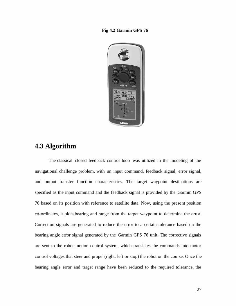
Fig 4.2 Garmin GPS 76
4.3 Algorithm
The classical closed feedback control loop was utilized in the modeling of the
navigational challenge problem, with an input command, feedback signal, error signal,
and output transfer function characteristics. The target waypoint destinations are
specified as the input command and the feedback signal is provided by the Garmin GPS
76 based on its position with reference to satellite data. Now, using the present position
co-ordinates, it plots bearing and range from the target waypoint to determine the error.
Correction signals are generated to reduce the error to a certain tolerance based on the
bearing angle error signal generated by the Garmin GPS 76 unit. The corrective signals
are sent to the robot motion control system, which translates the commands into motor
control voltages that steer and propel (right, left or stop) the robot on the course. Once the
bearing angle error and target range have been reduced to the required tolerance, the
28
robot reaches its target destination waypoint. Now, the process continues until all target
waypoints in the input file are navigated.
The navigational challenge field also has different kinds of obstacles which have to
be avoided by the robot while navigating given waypoints. The Bearcat III uses a SICK
laser scanner for obstacle avoidance which takes the routine in its control whenever there
is an obstacle in the range. Also, obstacle avoidance has a similar classical feedback
control loop used for the GPS navigation. Once the robot effectively evades the obstacles,
the original target waypoint is restored and the navigational routine is resumed.
4.4 Implementation
The implementation of GPS navigation feedback control loop consists of the Garmin
76 GPS unit, Galil DMC motion controller, SICK laser scanner, and the main onboard
computer. The input file of the target waypoints has the precedence of the waypoints
records to be navigated by the robot. The records are then stored in the memory as an
array. Each target waypoint is sequentially selected from the waypoint coordinate array
and the target coordinates are formatted into a NMEA $GPWPL (Waypoint Location)
sentence that is transmitted to the Garmin 76 GPS unit via the RS-232 port interface.
This message is sent to the Garmin 76 GPS unit and it sets the active target waypoint in
the GPS unit’s memory, this is the command signal. Once set, the waypoint coordinate is
used by the GPS unit to calculate bearing and range to the target waypoint. The Garmin
76 unit must be set to NMEA interface mode and navigate to waypoint mode with the
target waypoint name (ID) selected. Once in NMEA mode, the Garmin 76 unit transmits
various NMEA sentences with GPS navigational data 32. The feedback and error signal
29
information is transmitted in the NMEA $GPRMB (Recommended minimum navigation
information) sentence.
Garmin GPS 76 sends the $GPRMB ASCII sentence to the main computer where
it is parsed to obtain the bearing and range to destination waypoint data, which is the
error signal. The main computer sends either turn left or turn right correction signal to the
robot motion control system based on the bearing to target value. The robot turns to the
commanded correction angle until the GPS unit bearing error feedback signal is within
the selected tolerance. The process continues as the robot reaches the first waypoint for
the next target waypoint record. The laser scanner sends correction signal when the robot
is in obstacle avoidance mode to turn the robot until the obstacle is no longer obstructs
the robot. The robot computer processes the digital feedback control algorithm code and
sends correction command to the robot motion control system apart from interfacing all
the systems involved.
The Garmin 76 GPS unit is represented in the navigation code by a C++ GPS
class that has member functions into a single GPS object that can be used in the C++
code to implement the feedback control loop. The functions defined in the GPS class are:
1. void GPS::readGpsData(void){} - Reads gps data from serial port and returns a
pointer to a string array containing the data.
2. void GPS::getGpsData(struct gpsdata* t){} - copies the contents of the private
member variable N8MEA into a gpsdata structure and this function allows outside
access to the private member variable NMEA by making a copy of the structure
into the gpsdata structure pointed to by the gps data structure in the function
parameter list.
30
3. void GPS::CreateWaypointFile(void) {} - a waypoints data file is created through
user interface input waypoint data structure file written.
4. void GPS::SelectWaypoint(int select) {} - selects an active waypoint function and
takes waypoint number as a parameter
5. void GPS::InputWaypoints(void){} - Reads the input va lues of waypoint
information
6. void GPS::printInfo(void){} - Prints gps class data member contents to screen.
4.5 Experimental Test Setup and Results
Testing was done based on the outline given in the Annual Intelligent Ground
Vehicle Competition navigational challenge guidelines. Extensive testing resulted in
winning the third prize in Navigational challenge of IGVC 2003 with eight target
waypoints points. Using the handheld Garmin GPS 76, the latitude and longitude of each
marked position was determined and recorded in the input file. Firstly, the robot was
subject to manual navigation testing. The angle and distance information from GPS
navigation computer program was used to determine the steering direction information.
The values were manually input into the robot steering command prompt which turns the
robot in the direction specified. Once the turn angle was manually set, the robot was
given the command to move a line distance equal to the range to the target waypoint as
displayed by the GPS navigation computer program. The purpose of the manual testing
was verification of GPS unit interface and output data. Extensive testing proved that GPS
navigation algorithm worked satisfactorily albeit an error of twelve feet which almost
equals the advertised accuracy of the GPS unit in Waas mode.
31
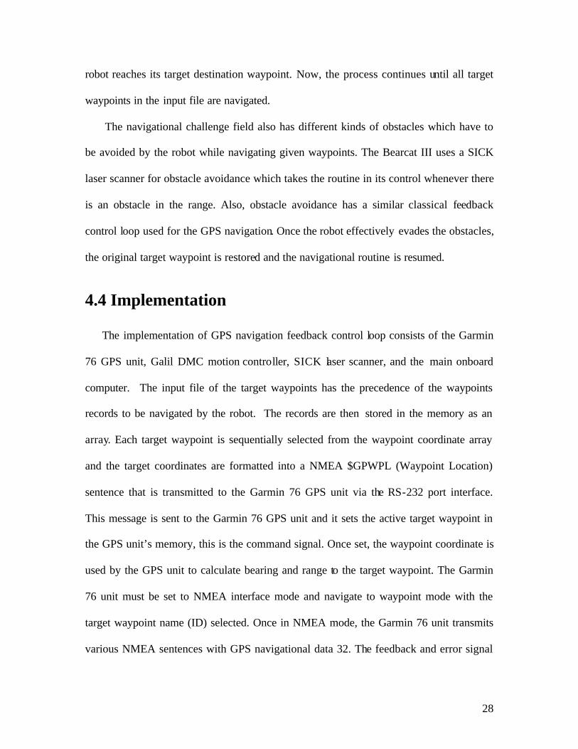
Fig 4.3 Team with III Prize in Navigational Challenge in IGVC 2003
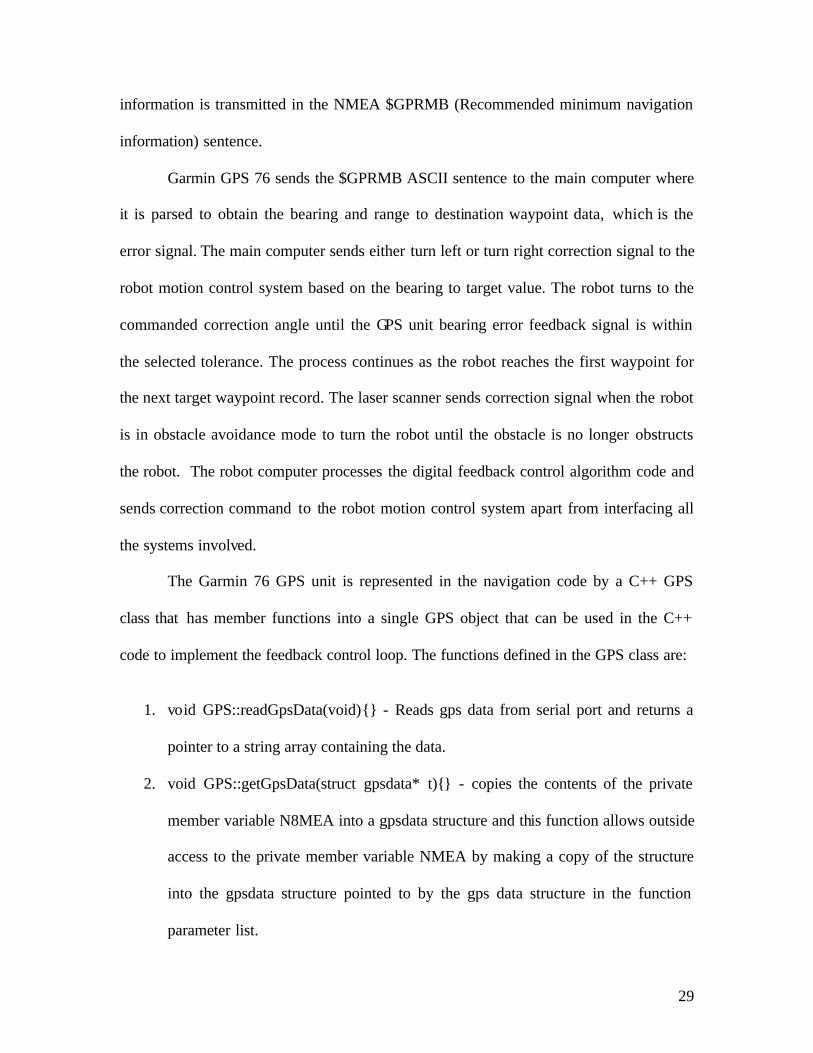
Fig 4.4 Action during Navigational Challenge in IGVC 2003

32
Chapter 5 Conclusion and Directions for Future Research
The technology of the Global Positioning System is allowing for huge changes in
society. The applications using GPS are constantly growing. The cost of the receivers is
dropping while at the same time the accuracy of the system is improving. GPS will soon
be at least as pervasive as the cell phone. As a matter of fact, GPS is now standard in
every cell phone sold in the U.S. “The U.S. Federal Communications Commission has
mandated that by October 2001, wireless carriers must be able to pinpoint and report the
location of all 911 calls by integrating GPS systems into their cellular phones. Emergency
crews can then use this information to reach their destinations more quickly.” The
potential applications of GPS are vast.
GPS is often used in conjunction with a GIS (geographical information system) to
provide location information and directions in personal automobiles. The potential for
GPS in our personal transportation is much more extensive than driving directions. Once
perfected, auto driving system would permit unimpeded traffic flow, significantly reduce
traffic jams, and bring about an unprecedented increase in the safety of the automobile.
However, the direct use of GPS on automated guided vehicles in manufacturing is
currently limited. The biggest obstacle in direct GPS application is the accuracy of the
GPS, which can be improved by also using two or more ground-based receivers. One
receiver can monitor the variations in the GPS signal and communicate those variations
to the other which can then correct its calculations for better accuracy. In the future, one
can combine the GPS signal with local sensors such as the existing vision and laser
33
scanner signals to allow a robot to move from one point to the next and at the same time
avoid obstacles on the course. If successfully tested, this has tremendous potential in
manufacturing applications.
Manufacturing companies will benefit greatly from having better control of their
supply chains by knowing the location of raw materials, processed goods and inventory.
Managers can expect a steady increase in cohesion of not only the supply chain, but of
the entire production and administrative processes, as new and better GPS related
applications continue to bridge gaps in the current system, thus allowing cost
containment and increased customer service to occur simultaneously. The use of GPS
combined with local beacon should have a variety of application in material handling,
storage and retrieval.
Airlines may one day be able to use GPS, along with autopilot, to choose to fly
their planes without a pilot, thereby substantially reducing the risk of flight accidents.
Farmers will be able to program their machinery to plant, fertilize, irrigate, or harvest
their crops.
34
References
1. “Design report for Bearcat III,” UC Center for Robotics Research, 2002.
2. G.W. Ernst and A. Newell, “GPS: a case study in generality and problem solving,”
New York, Academic Press, 1997.
3. S.A. Spiegel, “Navigation and control technologies for unmanned systems,” SPIE--the
international Society for Optical Engineering, April 1996.
4. 9 P.H. Dana, “Global Positioning Systems Overview”, 1995.
5. Garmin International Inc., “Garmin GPS 76 User manual”, July 2001.
6. A. N. Lorimer, “Global Navigation: A GPS User's Guide”, Lloyd's of London Press,
1994.
7. S. Modi, “Comparison of three obstacle avoidance methods for an autonomous guided vehicle,”
University of Cincinnati, 2002.
8. P. Ming, M. Saxena, S. Michalske, E.L. Hall, M Tedder, “Application of GPS on a
mobile robot,” University of Cincinnati, 1999.
9. P.H. Dana, “Global Positioning System Time Dissemination for Real-Time
Applications,” Real Time Systems, pp. 9-40, 1997
10. B. Sterzbach, “GPS-based Clock Synchronization in a Mobile, Distributed Real-Time
System,” Real Time systems, pp 63-75, 1997.
11. R.J. Cosentino, D.W. Diggle, “Differential GPS,” Understanding GPS, 1996
12. E. D. Kaplan, “Understanding GPS – Principles and Applications,” Artch House
Publishers, 1996
35
13. W. Michiko, F. Mashashi, K. Yukinori, “Intelligent AGV driving toward an
autonomous decentralized manufacturing system,” Robotics and Computer Integrated
Manufacturing, Vol 17, Issue 1-2, pp 57-64, February, 2001
14. R.J. Mantel, H.R.A. Landeweerd, “Design and Operational Control of an AGV,”
International Journal of Production Economics, Vol 41, Issue 1-3, pp 257-266, 1995
15. G.X. Tiemeyer, B. Lipp, “High Precision Navigation with wide area DGPS,”
Proceedings of DSNS, Amsterdam, 1995
16. C.R. Payne, “Navstar Global Positioning System: 1982, Proceedings of the Third
International Symposium on Satellite Doppler Positioning,” New Mexico State
University, 1982
17. DOD/DOT, “Federal Radio navigation Plan, National Technical Information Service,
Springfield, Virginia,” National Technical Information Service, 1995.
18. NAPA, “GPS: Charting the Future, Joint Report of NAPA and NRC,” National
Technical Information Service, Edition 1, 1995
19. W. Bellingham, “Navigation and control technologies for unmanned systems,” SPIE -
International Society for Optical Engineering, 1996
20. http://www.garmin.com
21. http://www.motorola.com/ies/GPS/products/