Embed Size (px)
Citation preview
UNIVERSITY OF ENGINEERING & MANAGEMENT,JAIPURLecture-wise Plan
Subject Name: Electric Drives Subject Code-EE701Year: 4th Year Semester: Eight
ModuleNumber
Topics Number of Lectures
1
Electric Drive: 5L
1. Concept, classification, parts andadvantages of electrical drives.
.
1
2. Types of Loads, Components of loadtoques, Fundamental torque equations,Equivalent value of drive parameters forloads with rotational and translationalmotion..
2
3. Determination of moment of inertia,Steady state stability, Transient stability
1
4. Multi quadrant operation of drives. Loadequalization
1
2
Motor power rating: 6L1. Thermal model of motor for heating and
cooling, classes of motor duty2
2. Determination of motor rating forcontinuous, short time and intermittentduty.
2
3. Equivalent current, torque and powermethods of determination of rating forfluctuating and intermittent loads
1
4. Effect of load inertia & environmentalfactors
1
3.
Stating of Electric Drives: 6L1. Effect of starting on Power supply, motor
and load\2
2. Methods of stating of electric motors.Acceleration time Energy relation duringstating,
2
3. Methods to reduce the Energy loss duringstarting 2
4Braking of Electric Drives: 2L
1. Types of braking, braking of DC motor,Induction motor and Synchronous motor,Energy loss during braking
2
5Dc Motor Drives: 6L
1. Modelling of DC motors, State spacemodelling, block diagram &Transferfunction
2
2. Single phase, three phases fully controlledand half controlled DC drives. Dualconverter control of DC drives
2
3. Power factor, supply harmonics and ripplein motor current chopper controlled DC 2
motor drives
6Induction motor drives: 4L
1. Stator voltage variation by three phasecontrollers, Speed control usingchopper resistance in the rotor circuit,slip power recovery scheme,
2
2. Pulse width modulated inverter fedand current source inverter fedinduction motor drive. Volts/hertzcontrol, vector or filed orientedcontrol
2
7
Synchronous motor drives: 4L1. Variable frequency control, Self Control 2
2. Voltage source inverter fed synchronousmotor drive, Vector control. 2
8
Industrial application: 3L
1. Introduction to Solar and Battery PoweredDrive, 1
2. Stepper motor, Switched Reluctancemotor Drive 1
3. Drive consideration for Textile mills, Steelrolling mills, Cement mills, Paper mills,Machine tools. Cranes & hoist drives 1
Total Number Of Hours = 36
Assignment:
Module1 (Electric Drives)
1. Describe the four quadrant operation of electrical drives.2. Determine the steady state and transient stability of electric drives3. State the factors that can influence the choice of a motor to drive the load
Module 2 (Motor Power Rating)1. Mention the Effect of load inertia & environmental factors on motor power rating
Module 3 (Starting of Electric Drives)1. Discuss the different starting methods for different motors.
Module 4 (Braking of Electric Drives)1. What is Braking? What are the different methods of braking of a Dc Motor.
Module 5 (Dc Motor Drive)1. What is dynamic braking for dc motor?2. Block diagram of the speed controller for speed control using armature voltage
change3. Describe Run-up of series D.C. motor with resistance in armature circuit.
Module 6 (Induction Motor Drive)

UNIVERSITY OF ENGINEERING & MANAGEMENT,JAIPURLecture-wise Plan
1. Define plugging of 3 phase induction motor2. Give the types of braking used for 3 phase induction motor.3. Define regenerative braking of 3 phase induction motor
Module 7 (Industrial Application)1. How we can consider the drives for Textile mills, Steel rolling mills, Cement mills,
Paper mills
UNIVERSITY OF ENGINEERING & MANAGEMENT,JAIPURLecture-wise Plan
Subject Name: Utilization Of Electric Power Subject Code: EE-702Year: 4th Year Semester: 7th
ModuleNumber
Topics Numberof
Lectures
1
Chapter 1: Traction 10L
1. System of Traction Electrification. 1L
2. Train movement & energy consumption (Speed-time curves, Crestspeed, Average speed & Schedule speed).
4L
3. Factors affecting energy consumption (Dead weight, Accelerationweight & Adhesion weight).
3L
4. Protective devices. 2LChapter 2: Electric Traction motor & their control 10L
1. Starting, braking with special emphasis on power electroniccontrollers.
4L
2. Current collector 1L3. Interference with telecommunication circuit.. 3L4. A brief outline of linear Induction motor principle in Traction. 2L
2
Chapter 3: Illumination 10L
1. Laws of illumination. 1L2. Polar curves. 1L
3. Photometry. 1L
4. Integrating sphere. 1L
5. Types of Lamps: Conventional and Energy Efficient. 2L
6. Basic principle of Light control. 1L
7. Different lighting scheme & their design methods. 2L
8. Flood and Street lighting. 1L
3
Chapter 4: Heating 6L
1. Types of heating 1L
2. Resistance heating, Induction heating. 2L
3. Arc furnace. 1L
4. Dielectric heating. 1L
5. Microwave heating. 1L
Chapter 5: Welding 6L
1. Resistance welding, Arc welding. 1L

2. Ultrasonic welding, Electron bean welding, Laser beamwelding.
2L
3. Requirement for good welding 1L
4. Power supplies for different welding schemes 2L
Total Number Of Hours = 42L
Shubhajit Pal Prof. Aniruddh MukherjeeFaculty In-Charge HOD, EE Dept.
Assignment:Module-1(Traction & Electric Traction motor & their control):
1. Describe the topology of boost converter based speed control method of tractionmotor with suitable diagram and waveforms (DC motor).
2. Drive the expression of the tractive effort exerted by train wheel in terms of tractionmotor torque, gear ratio, wheel diameter and efficiency of transmission of powerthrough gears with suitable diagram.
3. What is the effect of a train going up a gradient on the required tractive effort to besupplied by the traction motor? Also drive the expression of that tractive effort
4. An electric train has an average speed of 40kmph on a level track between stops1.6Km apart at suburban locality. The run is to be approximated as a simplequadrilateral speed time curve. It is accelerated at 2.0 kmphps and achieves amaximum speed of 64kmph.The coasting and braking retardation of this run is 0.16kmphps & 3.2 kmphps respectively. Draw the speed-time curve indicating duration ofacceleration, coasting and breaking periods.
Module-2 (Illumination):1. Differentiate between “illumination” and “luminous intensity”. Also write down the
properties of good illumination2. Describe stroboscopic effect. What are the methods that can be employed to minimize
this effect?3. Two points X and Y in a horizontal plane are needed to be illuminated. A light source
with uniform intensity is installed directly 20m above the point X. If illumination atpoint X is five times greater than point Y, then how far is point Y from point X
Module-3 (Heating & Welding):1. What are the important features of electric heating? What is the basic principle of
induction heating?2. Describe the applications of induction heating. Describe with the help of a neat
sketch, the working of a vertical core type induction furnace and its variousadvantages.
3. Explain the following termsa. Resistance weldingb. Ultrasonic welding

UNIVERSITY OF ENGINEERING & MANAGEMENT,JAIPURLecture-wise Plan
Subject Name: Utilization Of Electric Power Subject Code: EE-702Year: 4th Year Semester: 7th
c. Laser welding
UNIVERSITY OF ENGINEERING & MANAGEMENT,JAIPURLecture-wise Plan
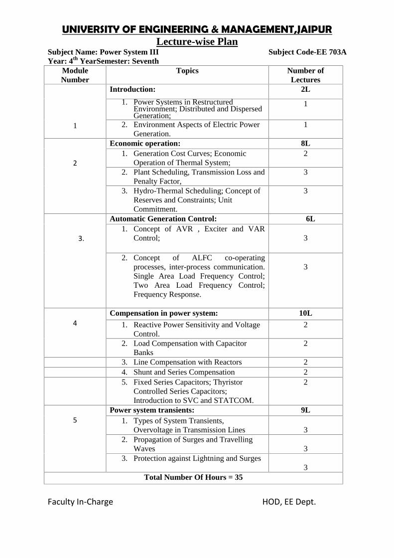
Subject Name: Power System III Subject Code-EE 703AYear: 4th YearSemester: Seventh
ModuleNumber
Topics Number ofLectures
1
Introduction: 2L
1. Power Systems in RestructuredEnvironment; Distributed and DispersedGeneration;
1
2. Environment Aspects of Electric PowerGeneration.
1
2
Economic operation: 8L1. Generation Cost Curves; Economic
Operation of Thermal System;2
2. Plant Scheduling, Transmission Loss andPenalty Factor,
3
3. Hydro-Thermal Scheduling; Concept ofReserves and Constraints; UnitCommitment.
3
3.
Automatic Generation Control: 6L1. Concept of AVR , Exciter and VAR
Control; 3
2. Concept of ALFC co-operatingprocesses, inter-process communication.Single Area Load Frequency Control;Two Area Load Frequency Control;Frequency Response.
3
4Compensation in power system: 10L
1. Reactive Power Sensitivity and VoltageControl.
2
2. Load Compensation with CapacitorBanks
2
3. Line Compensation with Reactors 24. Shunt and Series Compensation 25. Fixed Series Capacitors; Thyristor
Controlled Series Capacitors;Introduction to SVC and STATCOM.
2
5Power system transients: 9L
1. Types of System Transients,Overvoltage in Transmission Lines 3
2. Propagation of Surges and TravellingWaves 3
3. Protection against Lightning and Surges3
Total Number Of Hours = 35
Faculty In-Charge HOD, EE Dept.
Assignment:Module-1:
1. On what parameters does the layout of (a) thermal power plant (b) hydel power plantdepends?
2. What are the environmental aspect that influence the installation of a hydel powerplant?
Module-2:1. Let us consider a generating station that contains a total number of threegenerating units. The
fuel costs of these units are given by
The generation limit sof the units are as follows:
The total load that these units supply varies between 90 MW and 1250 MW. Assuming thatall thethree units are operational all the time, compute the economic operating settings as the load changes.
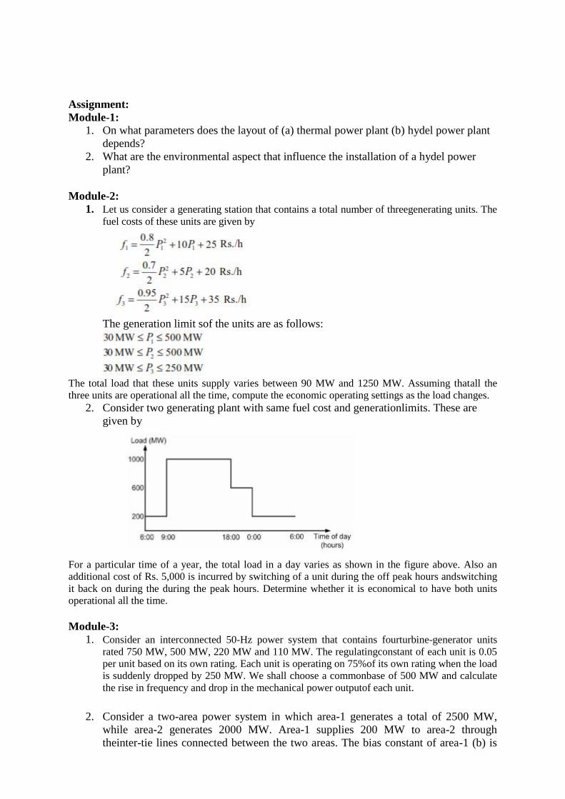
2. Consider two generating plant with same fuel cost and generationlimits. These aregiven by
For a particular time of a year, the total load in a day varies as shown in the figure above. Also anadditional cost of Rs. 5,000 is incurred by switching of a unit during the off peak hours andswitchingit back on during the during the peak hours. Determine whether it is economical to have both unitsoperational all the time.
Module-3:1. Consider an interconnected 50-Hz power system that contains fourturbine-generator units
rated 750 MW, 500 MW, 220 MW and 110 MW. The regulatingconstant of each unit is 0.05per unit based on its own rating. Each unit is operating on 75%of its own rating when the loadis suddenly dropped by 250 MW. We shall choose a commonbase of 500 MW and calculatethe rise in frequency and drop in the mechanical power outputof each unit.
2. Consider a two-area power system in which area-1 generates a total of 2500 MW,while area-2 generates 2000 MW. Area-1 supplies 200 MW to area-2 throughtheinter-tie lines connected between the two areas. The bias constant of area-1 (b) is
UNIVERSITY OF ENGINEERING & MANAGEMENT,JAIPURLecture-wise Plan
875 MW/Hz and that of area-2 (b) is 700 MW/Hz. With the two areas operating in thesteady state, the load of area-2 suddenly increases by 100 MW. It is desirable thatarea-2 absorbs itsown load change while not allowing the frequency to drift.
Module-4
1. Let us apply condition to maintain load voltage same as source voltage. Discuss thefeasibility of injected voltage in series with the line to obtain load voltage same assource voltage.
2. Discuss transient operation of DVR.
Module -5
1. How does the propagation constant and characteristic impedance define the voltageand current behaviour in a transmission line, explain.
2. What is the relation between transmitted voltage and SWR?
UNIVERSITY OF ENGINEERING & MANAGEMENT,JAIPURLecture-wise Plan
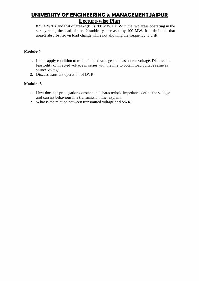
Subject Name:-Control system-III Subject Code:-EE703BYear:4th Year Semester: -SEVENTH
Module TOPICS
NO OFLECTUR
ES
Feedback Linearization:Motivation, Input–Output Linearization,Full-State
Linearization, State FeedbackControl 05
1 and Stabilization.
Sliding Mode Control:
2Overview of SMC, Motivating Examples, Stabilization of secondorder system; 05
Advantages and disadvantages.
Optimal control system:Formulation of optimal control problem: Minimum time, minimumenergy, minimum fuel
3 problem, state regulator, output regulator & tracking problems.Calculus of variations: Constrained fixed point and variable pointproblems, Euler
Lagrange equations.Problems with equality and inequality constraints. Engineeringapplication, Lagrange, 20
Mayer &Bolza problems, Pontryagin’s maximum (minimum) principle.Multiple decision process in discrete and continuous time - Thedynamic programming.Numerical solution of two point boundary value problems - the steepestdescent method
and the Fletcher - Powell Method.
TOTAL HOUR REQUIRED=30
ASSIGNMENTS:
MODULE 1:
1. Write short note on input output linearization2. Write short note state feedback control

MODULE 2:
1. Explain sliding mode control.2. Explain the stabilization methods of second order control system
MODULE 3:
1. Write a short note on optimal control methods.2. Explain the significance of Lagrange equations3. Write short notes on Mayer &Bolza problems, Pontryagin’s maximum (minimum)
principle
Faculty In-Charge HOD, EE Dept.
UNIVERSITY OF ENGINEERING & MANAGEMENT,JAIPURLecture-wise Plan
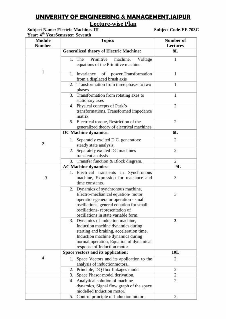
Subject Name: Electric Machines III Subject Code-EE 703CYear: 4th YearSemester: Seventh
ModuleNumber
Topics Number ofLectures
1
Generalized theory of Electric Machine: 8L
1. The Primitive machine, Voltageequations of the Primitive machine
1
1. Invariance of power,Transformationfrom a displaced brush axis
1
2. Transformation from three phases to twophases
1
3. Transformation from rotating axes tostationary axes
1
4. Physical concepts of Park’stransformations, Transformed impedancematrix
2
5. Electrical torque, Restriction of thegeneralized theory of electrical machines
2
2
DC Machine dynamics: 6L
1. Separately excited D.C. generators:steady state analysis,
2
2. Separately excited DC machinestransient analysis
2
3. Transfer function & Block diagram. 2
3.
AC Machine dynamics: 9L1. Electrical transients in Synchronous
machine, Expression for reactance andtime constants.
3
2. Dynamics of synchronous machine,Electro-mechanical equation- motoroperation-generator operation - smalloscillations, general equation for smalloscillations- representation ofoscillations in state variable form.
3
3. Dynamics of Induction machine,Induction machine dynamics duringstarting and braking, acceleration time,Induction machine dynamics duringnormal operation, Equation of dynamicalresponse of Induction motor.
3
4Space vectors and its application: 10L
1. Space Vectors and its application to theanalysis of inductionmotors.,
2
2. Principle, DQ flux-linkages model 23. Space Phasor model derivation, 24. Analytical solution of machine
dynamics, Signal flow graph of the spacemodelled Induction motor,
2
5. Control principle of Induction motor. 2
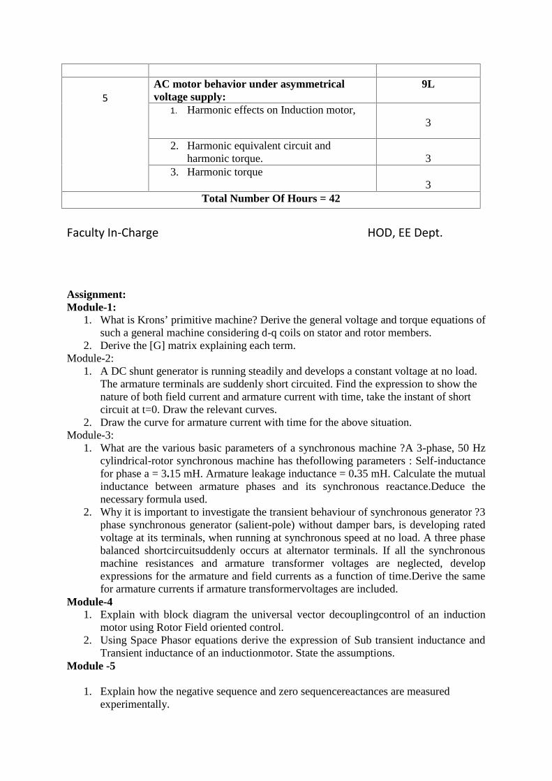
5AC motor behavior under asymmetricalvoltage supply:
9L
1. Harmonic effects on Induction motor,3
2. Harmonic equivalent circuit andharmonic torque. 3
3. Harmonic torque3
Total Number Of Hours = 42
Faculty In-Charge HOD, EE Dept.
Assignment:Module-1:
1. What is Krons’ primitive machine? Derive the general voltage and torque equations ofsuch a general machine considering d-q coils on stator and rotor members.
2. Derive the [G] matrix explaining each term.Module-2:
1. A DC shunt generator is running steadily and develops a constant voltage at no load.The armature terminals are suddenly short circuited. Find the expression to show thenature of both field current and armature current with time, take the instant of shortcircuit at t=0. Draw the relevant curves.
2. Draw the curve for armature current with time for the above situation.Module-3:
1. What are the various basic parameters of a synchronous machine ?A 3-phase, 50 Hzcylindrical-rotor synchronous machine has thefollowing parameters : Self-inductancefor phase a = 3.15 mH. Armature leakage inductance = 0.35 mH. Calculate the mutualinductance between armature phases and its synchronous reactance.Deduce thenecessary formula used.
2. Why it is important to investigate the transient behaviour of synchronous generator ?3phase synchronous generator (salient-pole) without damper bars, is developing ratedvoltage at its terminals, when running at synchronous speed at no load. A three phasebalanced shortcircuitsuddenly occurs at alternator terminals. If all the synchronousmachine resistances and armature transformer voltages are neglected, developexpressions for the armature and field currents as a function of time.Derive the samefor armature currents if armature transformervoltages are included.
Module-41. Explain with block diagram the universal vector decouplingcontrol of an induction
motor using Rotor Field oriented control.2. Using Space Phasor equations derive the expression of Sub transient inductance and
Transient inductance of an inductionmotor. State the assumptions.Module -5
1. Explain how the negative sequence and zero sequencereactances are measuredexperimentally.

UNIVERSITY OF ENGINEERING & MANAGEMENT,JAIPURLecture-wise Plan
2. Find the expression of current in the event of a sudden threephase short circuit in a 3phase induction motor. Assume that thetransient begin on no load and the referenceframe is attached tothe rotor.
UNIVERSITY OF ENGINEERING & MANAGEMENT,JAIPURLecture-wise Plan
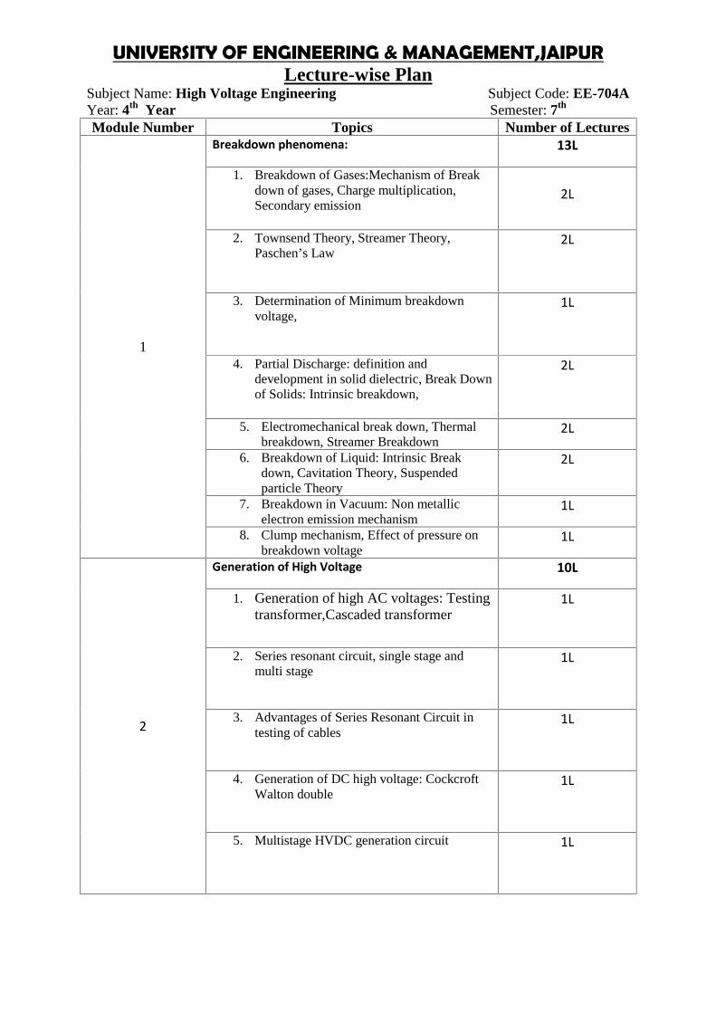
Subject Name: High Voltage Engineering Subject Code: EE-704AYear: 4th Year Semester: 7th
Module Number Topics Number of Lectures
1
Breakdown phenomena: 13L
1. Breakdown of Gases:Mechanism of Breakdown of gases, Charge multiplication,Secondary emission
2L
2. Townsend Theory, Streamer Theory,Paschen’s Law
2L
3. Determination of Minimum breakdownvoltage,
1L
4. Partial Discharge: definition anddevelopment in solid dielectric, Break Downof Solids: Intrinsic breakdown,
2L
5. Electromechanical break down, Thermalbreakdown, Streamer Breakdown
2L
6. Breakdown of Liquid: Intrinsic Breakdown, Cavitation Theory, Suspendedparticle Theory
2L
7. Breakdown in Vacuum: Non metallicelectron emission mechanism
1L
8. Clump mechanism, Effect of pressure onbreakdown voltage
1L
2
Generation of High Voltage 10L
1. Generation of high AC voltages: Testingtransformer,Cascaded transformer
1L
2. Series resonant circuit, single stage andmulti stage
1L
3. Advantages of Series Resonant Circuit intesting of cables
1L
4. Generation of DC high voltage: CockcroftWalton double
1L
5. Multistage HVDC generation circuit 1L
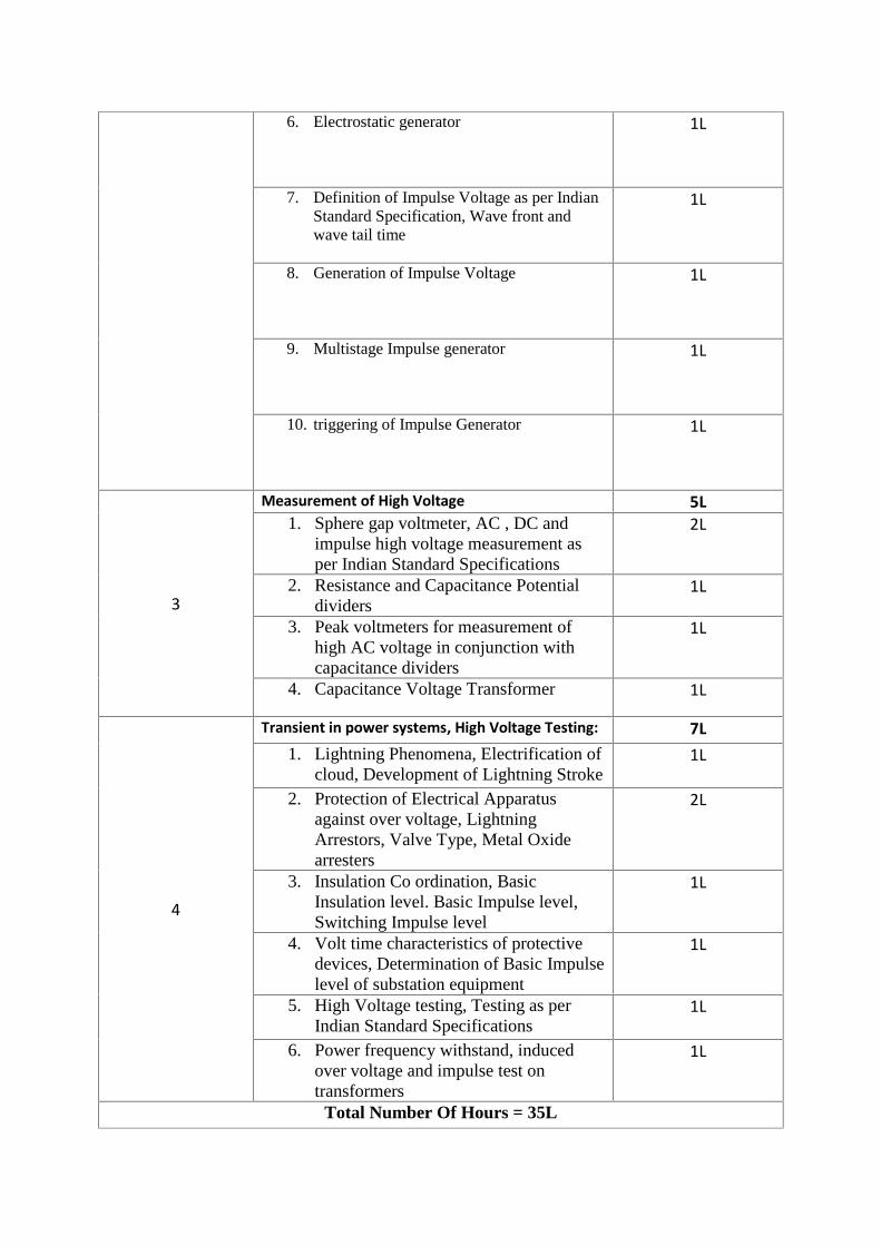
6. Electrostatic generator 1L
7. Definition of Impulse Voltage as per IndianStandard Specification, Wave front andwave tail time
1L
8. Generation of Impulse Voltage 1L
9. Multistage Impulse generator 1L
10. triggering of Impulse Generator 1L
3
Measurement of High Voltage 5L1. Sphere gap voltmeter, AC , DC and
impulse high voltage measurement asper Indian Standard Specifications
2L
2. Resistance and Capacitance Potentialdividers
1L
3. Peak voltmeters for measurement ofhigh AC voltage in conjunction withcapacitance dividers
1L
4. Capacitance Voltage Transformer 1L
4
Transient in power systems, High Voltage Testing: 7L1. Lightning Phenomena, Electrification of
cloud, Development of Lightning Stroke1L
2. Protection of Electrical Apparatusagainst over voltage, LightningArrestors, Valve Type, Metal Oxidearresters
2L
3. Insulation Co ordination, BasicInsulation level. Basic Impulse level,Switching Impulse level
1L
4. Volt time characteristics of protectivedevices, Determination of Basic Impulselevel of substation equipment
1L
5. High Voltage testing, Testing as perIndian Standard Specifications
1L
6. Power frequency withstand, inducedover voltage and impulse test ontransformers
1L
Total Number Of Hours = 35L
UNIVERSITY OF ENGINEERING & MANAGEMENT,JAIPURLecture-wise Plan
Subject Name: High Voltage Engineering Subject Code: EE-704AYear: 4th Year Semester: 7th
Assignment:Module-1(Breakdown phenomena):
1. Define Townsend’s first and second ionization coefficient , explain the Townsend’s criterionfor spark
2. State and explain Paschen’s law?3. Write short notes on corona discharge?4. Explain clearly the streamer mechanism of spark, with suitable sketches5. Classify various break down mechanisms occurring on liquid dielectrics and explain
them briefly?6. Explain the losses in dielectrics?7. What is the significance of Townsend’s first and second ionization coefficients?8. How breakdown occurs in impure liquid dielectrics?9. Describe thermal mechanism of breakdown in liquid dielectrics?10. Write short notes on intrinsic breakdown in solid dielectrics?
Module-2 (Generation of High Voltage):1. What is the Need for Generating High Voltages in Laboratory2. Draw a neat sketch of impulse generator and indicate the significance of each parameter
being used?3. Derive an expression for voltage efficiency of a multistage impulse generator?4. What are applications of High Voltages?5. Explain and compare the performance of half wave rectifier and voltage doubler
circuit?6. Show that the voltage drop in a n stage Cockroft Walton voltage multiplier circuit is
[ + - ]7. How Van De Graph Generator works, explain with a schematic diagram?8. A ten stage impulse generator has 0.350 µF condensers. The wave front and wave tail
resistances are 70 Ω and 2500Ω respectively. If the load capacitance is 2.5nF,determine the wave front and wave tail times of the impulse wave?
9. Explain how Trigatron Gap is used for tripping control in impulse generator circuit?10. What is ripple voltage? Show that the ripple voltage in a rectifier circuit depends upon
the load current and circuit parameters?
Module-3(Measurement of High Voltage):1. Explain sphere gap?2. How atmospheric condition and nearby earth object influence the measurement of
high voltage using sphere gap?3. Describe the principle of electrostatic voltmeter?4. How Chubb – Fortescue method is used for high voltage measurement5. Write short notes on capacitive voltage divider.6. Why capacitive voltage dividers are used instead resistive voltage dividers while
measuring high voltage?7. A generating voltmeter is required to measure voltage between 15 kV to 250 kV. If
the indicating meter reads a minimum current of 2 µA and maximum of 35 µA,

determine the capacitance of the generating voltmeter. Assume that the speed ofdriving synchronous motor is 1500 rpm.
8. Explain how peak voltmeter is used for high voltage measurement?
Module-4(Transient in power systems, High Voltage Testing):1. Describe the testing methods of line insulators?2. Explain the methods for testing cables?3. Explain the testing of circuit breakers?4. Write short notes on Insulation Co-ordination?5. Discuss the phenomenon of travelling wave over transmission line. Establish the
relation between the V & I waves travelling over the transmission line & for theirvelocity of propagation.
6. Deduce the general expression for reflection & refraction coefficient of travellingwave?
7. What do you understand by surge test or impulse test? Explain in detail?8. What is meant by making capacity of the circuit breaker?9. Explain how lightening strokes are developed?10. Describe volt time characteristics of protective devices?
UNIVERSITY OF ENGINEERING & MANAGEMENT,JAIPURLecture-wise Plan
Subject Name: Power plant engineering Subject Code-EE704BYear: 4th Year Semester: Eight
ModuleNumber
Topics Number of Lectures
1
Introduction: 4L
1. Power and energy, sources of energy.
1
2. Review of thermodynamic cycles relatedto power plants, fuels and combustioncalculations.
1
3. Load estimation, load curves, variousterms and factors involved in power plantcalculations
1
4. Effect of variable load on power plantoperation, Selection of power plant
1
2
Power plant economics and selection: 3L1. Effect of plant type on costs, rates, fixed
elements, energy elements. customerelements and investor’s profit;depreciation and replacement,
2
2. Theory of rates. Economics of plantselection, other consideration plantselection
1
3.
Steam power plant: 8L1. General layout of steam power plant 12. Power plant boilers including critical and
super critical boilers. Fluidized bedboilers, boilers mountings and accessories
2
3. Different systems such as coal handlingsystem, pulverizes and coal burners,combustion system, draft, ash handlingsystem, Dust collection system
2
4. Feed water treatment and condenser andcooling towers and cooling ponds
1
5. Turbine auxiliary systems such asgoverning, feed heating, reheating, flangeheating and gland leakage.
1
6. Operation and maintenance of steampower plant, heat balance and efficiencySite selection of a steam power plant
1
4Diesel power plant: 5L
1. General layout, Components of Dieselpower plant
1
2. Performance of diesel power plant, fuelsystem, lubrication system, air intake andadmission system, super charging system,exhaust system
2
UNIVERSITY OF ENGINEERING AND MANAGEMENT, JAIPURLecture-wise Plan
3. Diesel plant operation and efficiency, heatbalance, Site selection of diesel powerplant
1
4. Comparative study of diesel power plantwith steam power plant
1
5Gas turbine power plant: 3L
1. Layout of gas turbine power plant,Elements of gas turbine power plants, Gasturbine fuels, co generation
1
2. Auxiliary systems such as fuel, controlsand lubrication, operation andmaintenance
1
3. Combined cycle power plants, Siteselection of gas turbine power plant 1
6Nuclear power plant: 8L
1. Principles of nuclear energy, Layout ofnuclear power plant, Basic components ofnuclear reactions
2
2. Power station, Nuclear waste disposal,Site selection of nuclear power plants
1
3. Hydroelectric station Hydrology,Principles of working, applications, siteselection, classification and arrangements
1
4. Hydro-electric plants, run off size of plantand choice of units,operation and maintenance, hydrosystems, inter connected systems
2
5. Non Conventional Power PlantsIntroduction to non-conventional powerplants (Solar, wind, geothermal, tidal) etc.
1
7
Electrical system: 4L1. Generators and their cooling, transformers
and their cooling.2
2. Instrumentation Purpose, classification,selection and application, recorders andtheir use, listing of various controlrooms. Pollution due to power generation
2
Total Number Of Hours = 35
Assignment:Module 1 (Introduction)
1. What is load factor and Demand factor?2. The peak load on a power plant is 60 MW. The loads having maximum demands of
30 MW,20 MW, 10 MW and 14 MW are connected to the power plant. The capacityof the power plant is 80 MW and the annual load factor is 0.60. Estimate (a) averageload on the power plant, (b) the energy supplied per year, (c) the demand factor, (d)the diversity factor.
UNIVERSITY OF ENGINEERING & MANAGEMENT,JAIPURLecture-wise Plan
3. A power plant has the following annual factors; load factor =0.74, capacity factor=0.60, use factor =0.66, maximum demand is 60 MW. Estimate (a) the annual energyproduction, (b) the reserve capacity over and above the peak load, and (c) the hoursduring which the plant is not in service per year.
Module 2 (Power plant economic and selection)1. What are the economic consideration for plant selection
Module 3 (Steam Power Plant)1. A steam power plant with inlet steam to the h.p. turbine at 90 bar and 500 degree
centigrade and condensation at 40 degree centigrade produces 500 MW. It has onestage of reheat optimally placed which raises the steam temperature back to 500°C.One closed feed water heater with drains cascaded back to the condenser receivesbled steam at the reheat pressure, and the remaining steam is reheated and thenexpanded in the l.p. turbine. The h.p and l.p turbines have isentropic efficiencies of 92percent and 90 percent, respectively. The isentropic efficiency of the pump is 7percent, calculate (a) the mass flow rate of steam at turbine inlet in kg/s, (b) the cycleefficiency and (c) the cycle work ratio,Use TTD=-1.6°C.
2. An ideal steam power plant operates between 70 bar, 550°C and 0.075 bar. It hasseven feed water heaters, Find the optimum pressure and temperature at which theheaters operate.
3. A textile factory requires 10t/h of steam for process heating at 3 bar saturated and1000 kW of power, for which a back pressure turbine of 70 percent internal efficiencyis to be used. Find the steam condition required at the inlet of the turbine.
Module 4(Diesel power plant)1. A four-stroke CI engine of 3.5 litre capacity develops indicated power on average of
13.1 Kw/m3 of free air induced per minute, while running at 3600 rpm and having avolumetric efficiency of 82 per cent, referred to free air conditions of 1.013 bar and25°C. A blower driven mechanically from the engine is proposed to be installed forsupercharging. It works through a pressure of 1.75 and has an isentropic efficiency of70 per cent. Assume that at the end of the intake stroke the cylinders contain a volumeof charge equal to the swept volume, at the pressure and temperature of the deliveredair from the blower. Taking all mechanical efficiencies to be 80 per cent, estimate thenet increase in brake power of the engine due to supercharging.
2. Following are the observations made for a 20 minute trail of a two stroke dieselengine.Net brake load = 680 N, mep =3.0 bar, N= 360 rpm, Fuel consumption =1.56 kg,cooling water =160 kg, water inlet temperature =32°C, Water outlet temperature=57°C, Air used/kg fuel =30 kg, Room Temperature =27°C, Exhaust gas temperature=310°C, Cylindrical dimensions =210 mm bore *290 mm stroke, brake diameter=1m, calorific value of fuel =44MJ/Kg, steam formed per kg fuel in the exhaust =1.3kg, specific heat of steam in exhaust =2.093 KJ/KgK, Specific heat of dry exhaustgases =1.01 Kj/KgK.Calculate the indicated power and the brake power and make an energy balance of theengine.
Module 5 (Gas turbine power plant)

UNIVERSITY OF ENGINEERING AND MANAGEMENT, JAIPURLecture-wise Plan
1. What are the elements of gas turbine power plant2. What is combined cycle power plant
Module 6 (Nuclear Power plant)1. The half- life of radium 226 (atomic mass =226.095) 1620 yrs. Compute (a) the decay
constant, and (b) the initial activity of 1 g of radium 226.2. A certain nucleus has a cross-section of 10 barns for 2200 m/s neutrons. Find the
cross-section if the KE of the neutrons increases to 0.1 eV. The two neutrons energiesare withi1/V Range of the nucleus.
3. Calculate the macroscopic capture cross-section of water of density 1g/cm3. Themicroscopic capture cross-sections of hydrogen and oxygen are 0.332 barn and0.0002 barn, respectively.
Module 7 (Electrical system)1. What are the cooling procedure for transformer2. Discuss about the pollution due to the power generation.
UNIVERSITY OF ENGINEERING & MANAGEMENT,JAIPURLecture-wise Plan
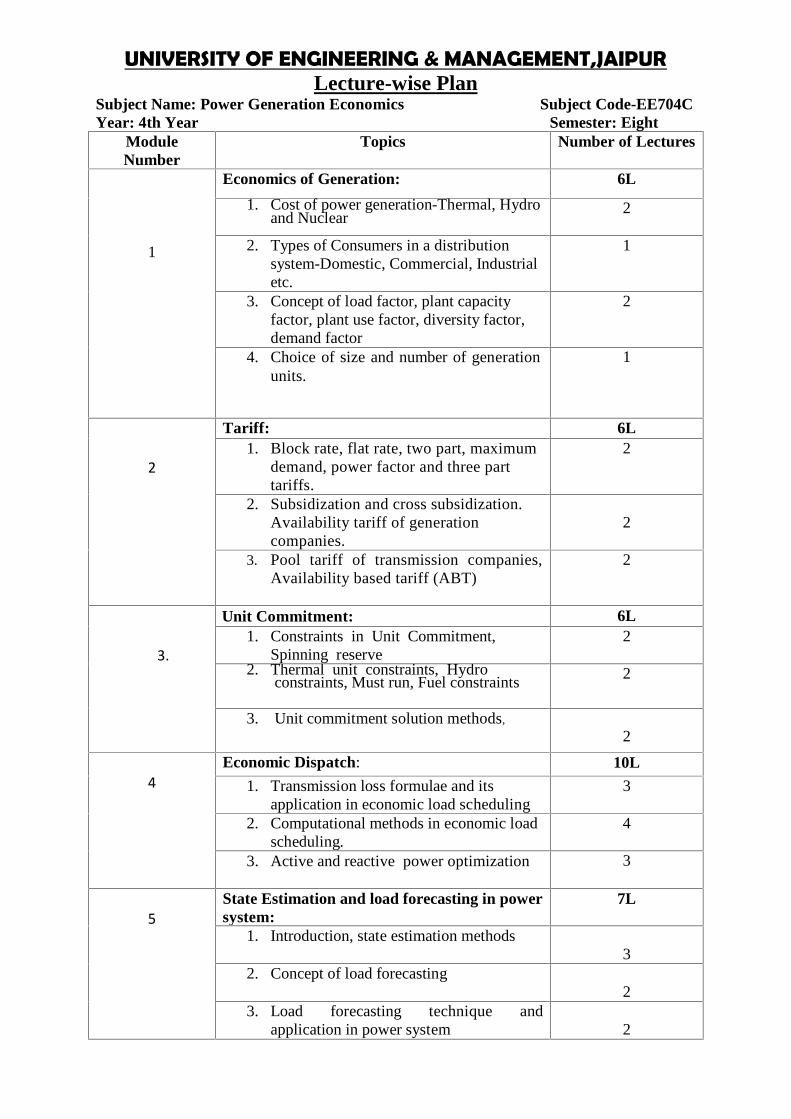
Subject Name: Power Generation Economics Subject Code-EE704CYear: 4th Year Semester: Eight
ModuleNumber
Topics Number of Lectures
1
Economics of Generation: 6L
1. Cost of power generation-Thermal, Hydroand Nuclear
2
2. Types of Consumers in a distributionsystem-Domestic, Commercial, Industrialetc.
1
3. Concept of load factor, plant capacityfactor, plant use factor, diversity factor,demand factor
2
4. Choice of size and number of generationunits.
1
2
Tariff: 6L1. Block rate, flat rate, two part, maximum
demand, power factor and three parttariffs.
2
2. Subsidization and cross subsidization.Availability tariff of generationcompanies.
2
3. Pool tariff of transmission companies,Availability based tariff (ABT)
2
3.
Unit Commitment: 6L1. Constraints in Unit Commitment,
Spinning reserve2
2. Thermal unit constraints, Hydroconstraints, Must run, Fuel constraints 2
3. Unit commitment solution methods,
2
4Economic Dispatch: 10L
1. Transmission loss formulae and itsapplication in economic load scheduling
3
2. Computational methods in economic loadscheduling.
4
3. Active and reactive power optimization 3
5State Estimation and load forecasting in powersystem:
7L
1. Introduction, state estimation methods3
2. Concept of load forecasting2
3. Load forecasting technique andapplication in power system 2

UNIVERSITY OF ENGINEERING AND MANAGEMENT, JAIPURLecture-wise Plan
Total Number Of Hours = 35
Assignment:
Module 1(Economics of Generation)1. Briefly Discuss about the types of consumers in distribution system2. How we can choice the size of the unit for a generation system3. What is plant factor and diversity factor
Module 2(Tariff)1. Discuss about the different types of tariff in generation system2. What is Availability based tariff (ABT)?3. Explain-“Subsidization and cross subsidization”
Module 3 (Unit Commitment)1. What are the Constraints in Unit Commitment,? What is Spinning reserve?2. Discuss the different unit constraints for thermal and hydro generation system3. What are the Unit commitment solution methods?
Module 4(Economic Dispatch)1. How we can optimize the active and reactive power?2. What are the Computational methods in economic load scheduling
Module 5 (State Estimation and load forecasting in power system)1. Explain- “ load forecasting”2. What are the different Load forecasting techniques? What are the application of load
forecasting techniques in power system3. Discuss about the state estimation methods.
UNIVERSITY OF ENGINEERING & MANAGEMENT,JAIPURLecture-wise Plan
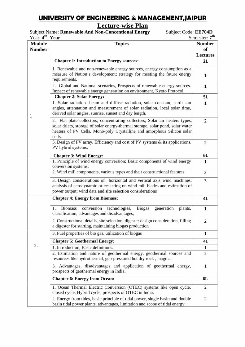
Subject Name: Renewable And Non-Concentional Energy Subject Code: EE704DYear: 4th Year Semester: 7th
ModuleNumber
Topics Numberof
Lectures
1
Chapter 1: Introduction to Energy sources: 2L1. Renewable and non-renewable energy sources, energy consumption as ameasure of Nation’s development; strategy for meeting the future energyrequirements.
1
2. Global and National scenarios, Prospects of renewable energy sources.Impact of renewable energy generation on environment, Kyoto Protocol.
1
Chapter 2: Solar Energy: 5L1. Solar radiation -beam and diffuse radiation, solar constant, earth sunangles, attenuation and measurement of solar radiation, local solar time,derived solar angles, sunrise, sunset and day length.
1
2. Flat plate collectors, concentrating collectors, Solar air heaters types,solar driers, storage of solar energy-thermal storage, solar pond, solar waterheaters of PV Cells, Mono-poly Crystalline and amorphous Silicon solarcells. solardistillation,solarstill,solarcooker,solarheating&coolingofbuildings,photovoltaics-solarcells, differenttypes
2
3. Design of PV array. Efficiency and cost of PV systems & its applications.PV hybrid systems.
2
Chapter 3: Wind Energy: 6L1. Principle of wind energy conversion; Basic components of wind energyconversion systems;
1
2. Wind mill components, various types and their constructional features 23. Design considerations of horizontal and vertical axis wind machines:analysis of aerodynamic or cesacting on wind mill blades and estimation ofpower output; wind data and site selection considerations
3
2.
Chapter 4: Energy from Biomass: 4L
1. Biomass conversion technologies, Biogas generation plants,classification, advantages and disadvantages,
1
2. Constructional details, site selection, digester design consideration, fillinga digester for starting, maintaining biogas production
2
3. Fuel properties of bio gas, utilization of biogas 1Chapter 5: Geothermal Energy: 4L1. Introduction, Basic definitions. 12. Estimation and nature of geothermal energy, geothermal sources andresources like hydrothermal, geo-pressured hot dry rock , magma.
2
3. Advantages, disadvantages and application of geothermal energy,prospects of geothermal energy in India.
1
Chapter 6: Energy from Ocean: 6L
1. Ocean Thermal Electric Conversion (OTEC) systems like open cycle,closed cycle, Hybrid cycle, prospects of OTEC in India.
2
2. Energy from tides, basic principle of tidal power, single basin and doublebasin tidal power plants, advantages, limitation and scope of tidal energy
2

3. Wave energy and power from wave, wave energy conversion devices,advantages and disadvantages of wave energy.
2
3.
Chapter 7: Magneto Hydrodynamic power generation: 3L1. Principle of MHD power generation, MHD system, Design problems anddevelopments
2
2. Gas conductivity, materials for MHD generators and future prospects. 1
4.
Chapter 8: Hydrogen Energy: 3L
1. Introduction, Hydrogen Production methods, Hydrogen storage,hydrogen transportation
2
2. Utilization of hydrogen gas, hydrogen as alternative fuel for vehicles. 1Chapter 9: Fuel cell: 3L
1. Introduction, Design principle and operation of fuel cell, Types of fuelcells 22. conversion efficiency of fuel cell, application of fuel cells 1
Total Number Of Hours = 36L
Shubhajit Pal Prof. Aniruddh MukherjeeFaculty In-Charge HOD, EE Dept.
Assignment:Module-11. Mention the different forms of energy.2. What is Kyoto protocol and what are its implications for developed and developing countries.3. Explain the different characteristics of PV system.4. With a neat diagram, explain how wind energy can be converted into electrical energy.
Module-21. What is the prospect of geothermal energy?2. What principles guide in the location of a geothermal power station?3. Write a short note on Biodiesel
Module-3:1. Write short notes on:(a) Magneto hydrodynamic energy (b) Wave energy2. Discuss the advantages and limitations of tidal energy.
Module-4:1. What is fuel cell? Discuss different types of fuel cell. What are the advantages of fuel cell energy?Discuss on alkaline fuel cell and hydrogen fuel cell.2. Discuss the various methods of hydrogen production.
UNIVERSITY OF ENGINEERING & MANAGEMENT,JAIPURLecture-wise Plan
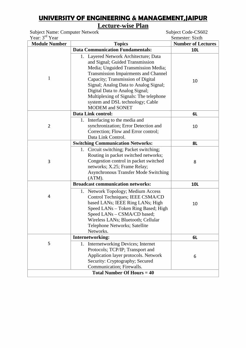
Subject Name: Computer Network Subject Code-CS602Year: 3rd Year Semester: SixthModule Number Topics Number of Lectures
1
Data Communication Fundamentals: 10L1. Layered Network Architecture; Data
and Signal; Guided TransmissionMedia; Unguided Transmission Media;Transmission Impairments and ChannelCapacity; Transmission of DigitalSignal; Analog Data to Analog Signal;Digital Data to Analog Signal;Multiplexing of Signals: The telephonesystem and DSL technology; CableMODEM and SONET
10
2
Data Link control: 6L1. Interfacing to the media and
synchronization; Error Detection andCorrection; Flow and Error control;Data Link Control.
10
3
Switching Communication Networks: 8L1. Circuit switching; Packet switching;
Routing in packet switched networks;Congestion control in packet switchednetworks; X.25; Frame Relay;Asynchronous Transfer Mode Switching(ATM).
8
4
Broadcast communication networks: 10L1. Network Topology; Medium Access
Control Techniques; IEEE CSMA/CDbased LANs; IEEE Ring LANs; HighSpeed LANs – Token Ring Based; HighSpeed LANs – CSMA/CD based;Wireless LANs; Bluetooth; CellularTelephone Networks; SatelliteNetworks.
10
5Internetworking: 6L
1. Internetworking Devices; InternetProtocols; TCP/IP; Transport andApplication layer protocols. NetworkSecurity: Cryptography; SecuredCommunication; Firewalls.
6
Total Number Of Hours = 40
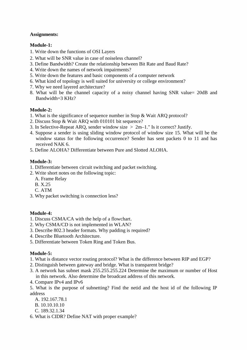
Assignments:
Module-1:1. Write down the functions of OSI Layers2. What will be SNR value in case of noiseless channel?3. Define Bandwidth? Create the relationship between Bit Rate and Baud Rate?4. Write down the names of network impairments?5. Write down the features and basic components of a computer network6. What kind of topology is well suited for university or college environment?7. Why we need layered architecture?8. What will be the channel capacity of a noisy channel having SNR value= 20dB and
Bandwidth=3 KHz?
Module-2:1. What is the significance of sequence number in Stop & Wait ARQ protocol?2. Discuss Stop & Wait ARQ with 010101 bit sequence?3. In Selective-Repeat ARQ, sender window size > 2m–1." Is it correct? Justify.4. Suppose a sender is using sliding window protocol of window size 15. What will be the
window status for the following occurrence? Sender has sent packets 0 to 11 and hasreceived NAK 6.
5. Define ALOHA? Differentiate between Pure and Slotted ALOHA.
Module-3:1. Differentiate between circuit switching and packet switching.2. Write short notes on the following topic:
A. Frame RelayB. X.25C. ATM
3. Why packet switching is connection less?
Module-4:1. Discuss CSMA/CA with the help of a flowchart.2. Why CSMA/CD is not implemented in WLAN?3. Describe 802.3 header formats. Why padding is required?4. Describe Bluetooth Architecture.5. Differentiate between Token Ring and Token Bus.
Module-5:1. What is distance vector routing protocol? What is the difference between RIP and EGP?2. Distinguish between gateway and bridge. What is transparent bridge?3. A network has subnet mask 255.255.255.224 Determine the maximum or number of Host
in this network. Also determine the broadcast address of this network.4. Compare IPv4 and IPv65. What is the purpose of subnetting? Find the netid and the host id of the following IPaddress
A. 192.167.78.1B. 10.10.10.10C. 189.32.1.34
6. What is CIDR? Define NAT with proper example?
UNIVERSITY OF ENGINEERING & MANAGEMENT,JAIPURLecture-wise Plan
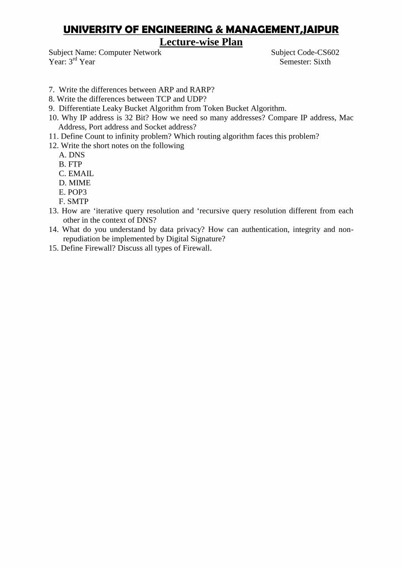
Subject Name: Computer Network Subject Code-CS602Year: 3rd Year Semester: Sixth
7. Write the differences between ARP and RARP?8. Write the differences between TCP and UDP?9. Differentiate Leaky Bucket Algorithm from Token Bucket Algorithm.10. Why IP address is 32 Bit? How we need so many addresses? Compare IP address, Mac
Address, Port address and Socket address?11. Define Count to infinity problem? Which routing algorithm faces this problem?12. Write the short notes on the following
A. DNSB. FTPC. EMAILD. MIMEE. POP3F. SMTP
13. How are ‘iterative query resolution and ‘recursive query resolution different from eachother in the context of DNS?
14. What do you understand by data privacy? How can authentication, integrity and non-repudiation be implemented by Digital Signature?
15. Define Firewall? Discuss all types of Firewall.
UNIVERSITY OF ENGINEERING & MANAGEMENT,JAIPURLecture-wise Plan
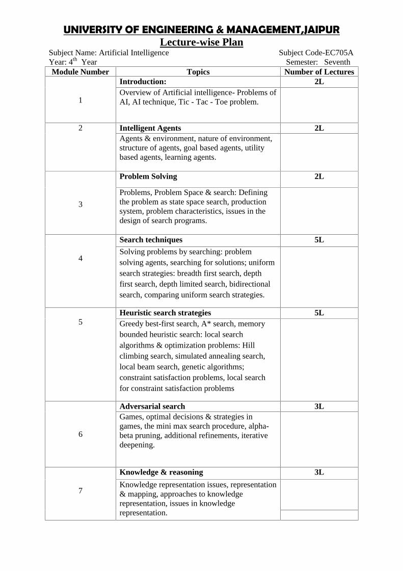
Subject Name: Artificial Intelligence Subject Code-EC705AYear: 4th Year Semester: SeventhModule Number Topics Number of Lectures
1
Introduction: 2LOverview of Artificial intelligence- Problems ofAI, AI technique, Tic - Tac - Toe problem.
2 Intelligent Agents 2LAgents & environment, nature of environment,structure of agents, goal based agents, utilitybased agents, learning agents.
3
Problem Solving 2L
Problems, Problem Space & search: Definingthe problem as state space search, productionsystem, problem characteristics, issues in thedesign of search programs.
4
Search techniques 5L
Solving problems by searching: problemsolving agents, searching for solutions; uniformsearch strategies: breadth first search, depthfirst search, depth limited search, bidirectionalsearch, comparing uniform search strategies.
5Heuristic search strategies 5LGreedy best-first search, A* search, memorybounded heuristic search: local searchalgorithms & optimization problems: Hillclimbing search, simulated annealing search,local beam search, genetic algorithms;constraint satisfaction problems, local searchfor constraint satisfaction problems
6
Adversarial search 3LGames, optimal decisions & strategies ingames, the mini max search procedure, alpha-beta pruning, additional refinements, iterativedeepening.
7
Knowledge & reasoning 3L
Knowledge representation issues, representation& mapping, approaches to knowledgerepresentation, issues in knowledgerepresentation.
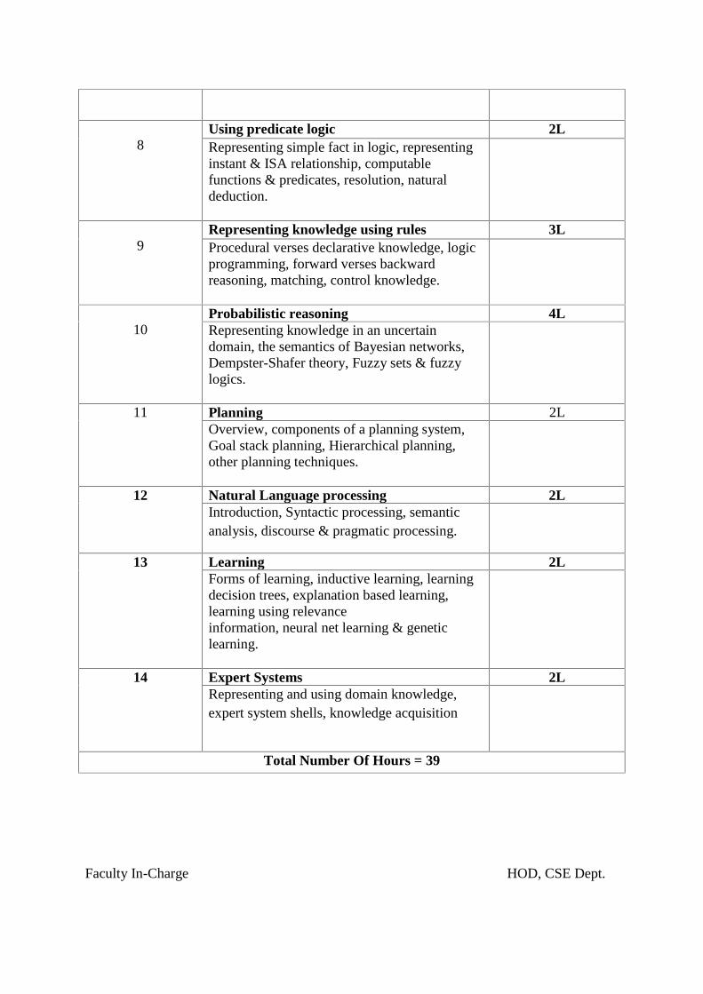
8Using predicate logic 2LRepresenting simple fact in logic, representinginstant & ISA relationship, computablefunctions & predicates, resolution, naturaldeduction.
9Representing knowledge using rules 3LProcedural verses declarative knowledge, logicprogramming, forward verses backwardreasoning, matching, control knowledge.
10Probabilistic reasoning 4LRepresenting knowledge in an uncertaindomain, the semantics of Bayesian networks,Dempster-Shafer theory, Fuzzy sets & fuzzylogics.
11 Planning 2LOverview, components of a planning system,Goal stack planning, Hierarchical planning,other planning techniques.
12 Natural Language processing 2LIntroduction, Syntactic processing, semanticanalysis, discourse & pragmatic processing.
13 Learning 2LForms of learning, inductive learning, learningdecision trees, explanation based learning,learning using relevanceinformation, neural net learning & geneticlearning.
14 Expert Systems 2LRepresenting and using domain knowledge,expert system shells, knowledge acquisition
Total Number Of Hours = 39
Faculty In-Charge HOD, CSE Dept.

UNIVERSITY OF ENGINEERING & MANAGEMENT,JAIPURLecture-wise Plan
Subject Name: Artificial Intelligence Subject Code-EC705AYear: 4th Year Semester: SeventhAssignments:
Module-I: Introduction
1. What do you mean by Artificial intelligence?2. Explain Tic - Tac - Toe problem.
Module-II: Intelligent Agents
1. Explain nature of environment2. Discuss the followings:
structure of agents goal based agents utility based agents Learning agents
Module-III: Problem Solving
1. Explain how the problem as state space search has defined?2. Define problem characteristics and issues in the design of search programs.
Module-IV: Search techniques
1. What do you mean by problem solving agents? searching for solutions2. Explain depth limited search, bidirectional search.
Module-V: Heuristic search strategies
1. Explain Greedy best-first search2. How Hill climbing search and simulated annealing search are different from each other?
Module-VI: Adversarial search
1. What do you mean by optimal decisions & strategies in games?2. Explain the mini max search procedure, alpha-beta pruning.
Module-VII: Knowledge & reasoning
1. Explain different knowledge representation issues, representation & mapping.2. Mention different approaches to knowledge representation. What are the issues in knowledge
representation?
Module-VIII: Using predicate logic
1. How you represent simple facts in logic?2. Explain ISA relationship, computable functions & predicates.

Module-IX: Representing knowledge using rules
1. Differentiate Procedural and declarative knowledge2. Explain logic programming. What are the differences between forward and backward
reasoning?
Module-X: Probabilistic reasoning
1. How you represent knowledge in an uncertain domain?2. Explain the semantics of Bayesian networks. What do you mean by Dempster-Shafer theory?
Module-XI: Planning
1. Explain the components of a planning system. What is Goal stack planning?2. What do you mean by Hierarchical planning?
Module-XII: Natural Language processing
1. Explain Syntactic processing in NLP.2. What do you mean by semantic analysis?
Module-XIII: Learning
1. Explain the different forms of learning. What do you mean by inductive learning, learningdecision trees, explanation based learning?
2. Differentiate neural net learning & genetic learning.
Module-XIV: Expert Systems
1. How do you representing and use domain knowledge?2. Explain expert system shells, knowledge acquisition.
UNIVERSITY OF ENGINEERING & MANAGEMENT,JAIPURLecture-wise Plan
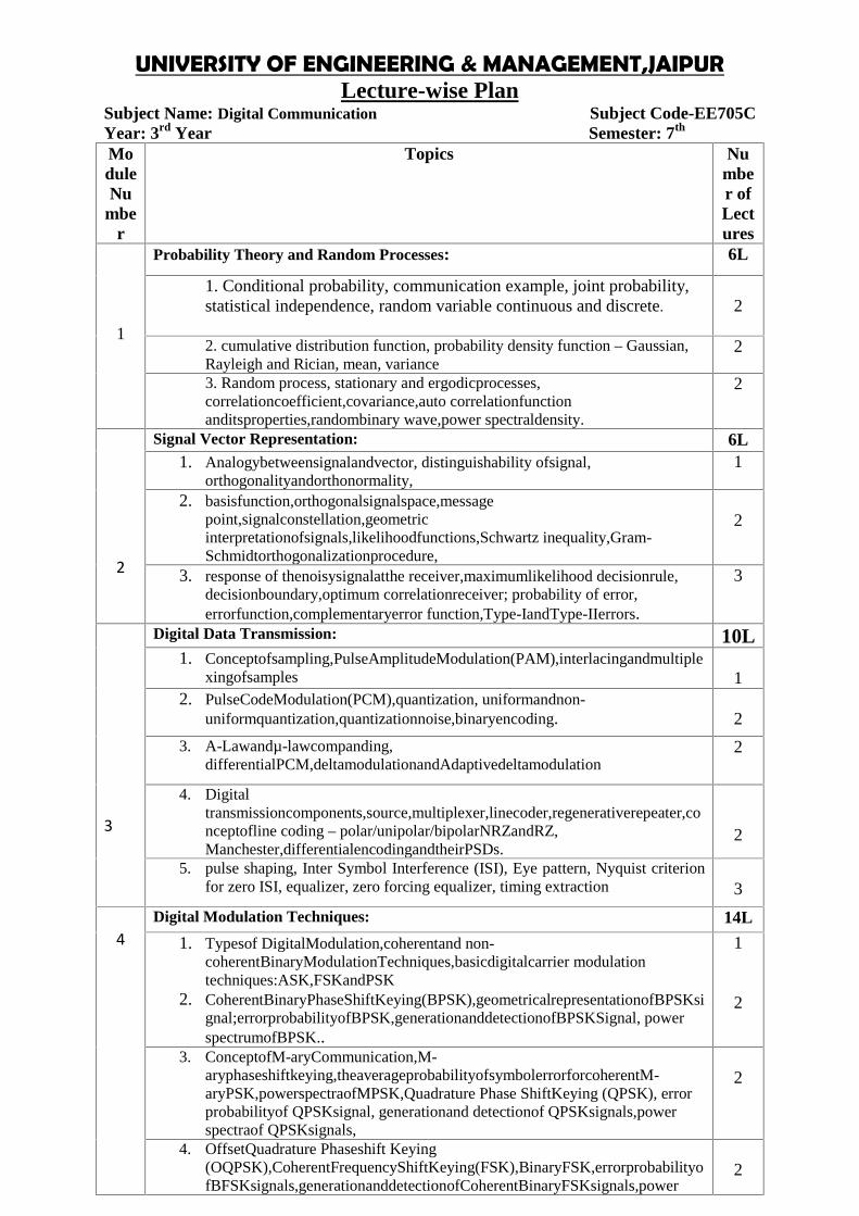
Subject Name: Digital Communication Subject Code-EE705CYear: 3rd Year Semester: 7th
ModuleNu
mber
Topics Number ofLectures
1
Probability Theory and Random Processes: 6L
1. Conditional probability, communication example, joint probability,statistical independence, random variable continuous and discrete. 2
2. cumulative distribution function, probability density function – Gaussian,Rayleigh and Rician, mean, variance
2
3. Random process, stationary and ergodicprocesses,correlationcoefficient,covariance,auto correlationfunctionanditsproperties,randombinary wave,power spectraldensity.
2
2
Signal Vector Representation: 6L1. Analogybetweensignalandvector, distinguishability ofsignal,
orthogonalityandorthonormality,1
2. basisfunction,orthogonalsignalspace,messagepoint,signalconstellation,geometricinterpretationofsignals,likelihoodfunctions,Schwartz inequality,Gram-Schmidtorthogonalizationprocedure,
2
3. response of thenoisysignalatthe receiver,maximumlikelihood decisionrule,decisionboundary,optimum correlationreceiver; probability of error,errorfunction,complementaryerror function,Type-IandType-IIerrors.
3
3
Digital Data Transmission: 10L1. Conceptofsampling,PulseAmplitudeModulation(PAM),interlacingandmultiple
xingofsamples 12. PulseCodeModulation(PCM),quantization, uniformandnon-
uniformquantization,quantizationnoise,binaryencoding. 2
3. A-Lawandµ-lawcompanding,differentialPCM,deltamodulationandAdaptivedeltamodulation
2
4. Digitaltransmissioncomponents,source,multiplexer,linecoder,regenerativerepeater,conceptofline coding – polar/unipolar/bipolarNRZandRZ,Manchester,differentialencodingandtheirPSDs.
2
5. pulse shaping, Inter Symbol Interference (ISI), Eye pattern, Nyquist criterionfor zero ISI, equalizer, zero forcing equalizer, timing extraction 3
4Digital Modulation Techniques: 14L
1. Typesof DigitalModulation,coherentand non-coherentBinaryModulationTechniques,basicdigitalcarrier modulationtechniques:ASK,FSKandPSK
2. CoherentBinaryPhaseShiftKeying(BPSK),geometricalrepresentationofBPSKsignal;errorprobabilityofBPSK,generationanddetectionofBPSKSignal, powerspectrumofBPSK..
1
2
3. ConceptofM-aryCommunication,M-aryphaseshiftkeying,theaverageprobabilityofsymbolerrorforcoherentM-aryPSK,powerspectraofMPSK,Quadrature Phase ShiftKeying (QPSK), errorprobabilityof QPSKsignal, generationand detectionof QPSKsignals,powerspectraof QPSKsignals,
2
4. OffsetQuadrature Phaseshift Keying(OQPSK),CoherentFrequencyShiftKeying(FSK),BinaryFSK,errorprobabilityofBFSKsignals,generationanddetectionofCoherentBinaryFSKsignals,power
2
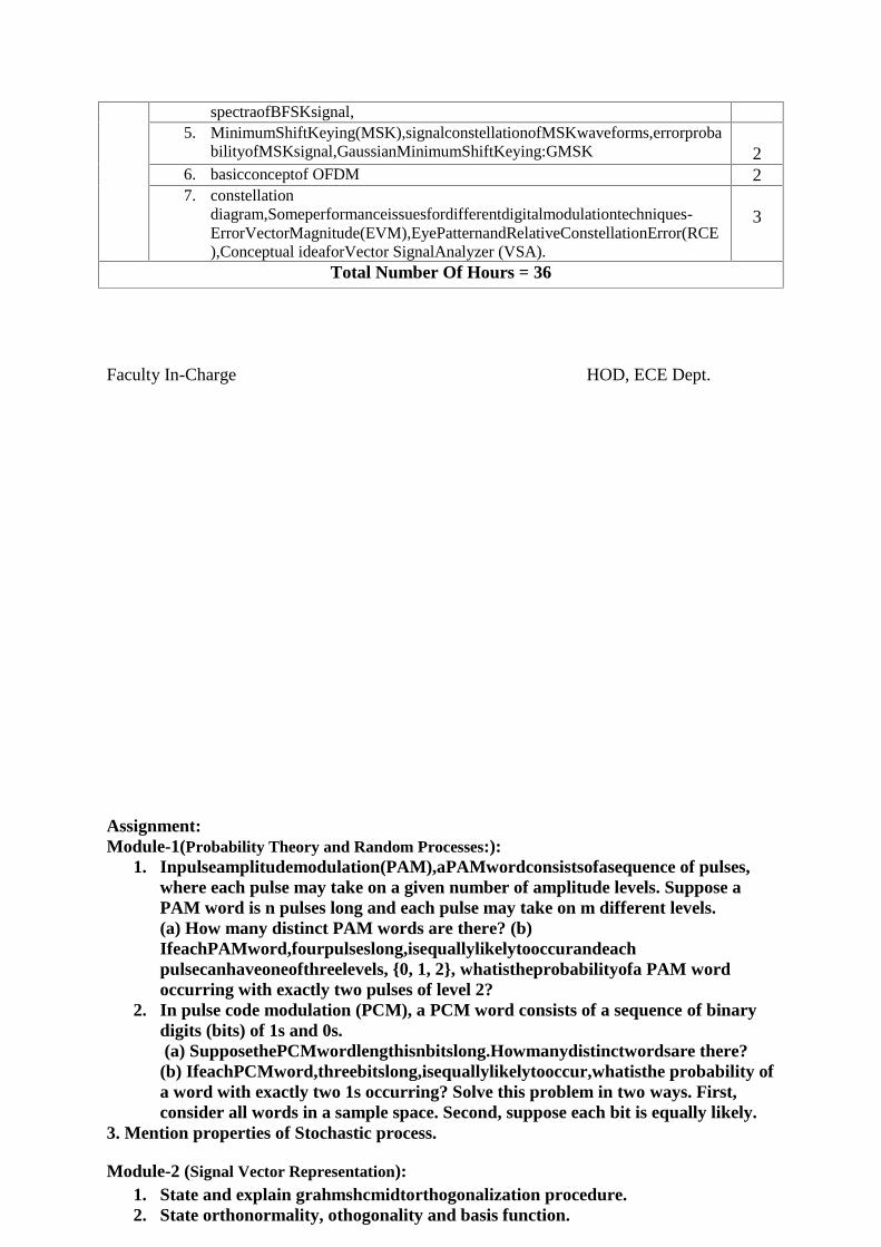
spectraofBFSKsignal,5. MinimumShiftKeying(MSK),signalconstellationofMSKwaveforms,errorproba
bilityofMSKsignal,GaussianMinimumShiftKeying:GMSK 26. basicconceptof OFDM 27. constellation
diagram,Someperformanceissuesfordifferentdigitalmodulationtechniques-ErrorVectorMagnitude(EVM),EyePatternandRelativeConstellationError(RCE),Conceptual ideaforVector SignalAnalyzer (VSA).
3
Total Number Of Hours = 36
Faculty In-Charge HOD, ECE Dept.
Assignment:Module-1(Probability Theory and Random Processes:):
1. Inpulseamplitudemodulation(PAM),aPAMwordconsistsofasequence of pulses,where each pulse may take on a given number of amplitude levels. Suppose aPAM word is n pulses long and each pulse may take on m different levels.(a) How many distinct PAM words are there? (b)IfeachPAMword,fourpulseslong,isequallylikelytooccurandeachpulsecanhaveoneofthreelevels, 0, 1, 2, whatistheprobabilityofa PAM wordoccurring with exactly two pulses of level 2?
2. In pulse code modulation (PCM), a PCM word consists of a sequence of binarydigits (bits) of 1s and 0s.(a) SupposethePCMwordlengthisnbitslong.Howmanydistinctwordsare there?(b) IfeachPCMword,threebitslong,isequallylikelytooccur,whatisthe probability ofa word with exactly two 1s occurring? Solve this problem in two ways. First,consider all words in a sample space. Second, suppose each bit is equally likely.
3. Mention properties of Stochastic process.
Module-2 (Signal Vector Representation):1. State and explain grahmshcmidtorthogonalization procedure.2. State orthonormality, othogonality and basis function.

UNIVERSITY OF ENGINEERING & MANAGEMENT,JAIPURLecture-wise Plan
3. Discuss about maximum likelihood rule for AWGN channel.4. Discuss about matched filter for optimum detection.
Module-3(Digital Data Transmission):1. What is companding? Why it is needed?2. Explain uniform and non-uniform quantization?3. What is Nyquist criterion for zero intersymbol interference?4. What is the function of raised cosine function?5. What are limitations of delta modulation?6. What is quantization noise?7. Given an input data: 010110, Represent it using the line codes.
Module-4(Digital Modulation Techniques):1. What is the difference between MSK and QPSK?2. With Proper equations and signal constellation explain the concept of Quadri
phase shift Keying.3. Explain the concept of OFDM.4. Draw an eye diagram and mention the significance of its different parts.
UNIVERSITY OF ENGINEERING & MANAGEMENT, JAIPURLecture-wise Plan
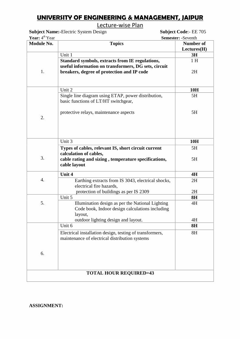
Subject Name:-Electric System Design Subject Code:- EE 705Year: 4th Year Semester: -SeventhModule No. Topics Number of
Lectures(H)
1.
Unit 1 3HStandard symbols, extracts from IE regulations,useful information on transformers, DG sets, circuitbreakers, degree of protection and IP code
1 H
2H
2.
Unit 2 10HSingle line diagram using ETAP, power distribution,basic functions of LT/HT switchgear,
protective relays, maintenance aspects
5H
5H
3.
Unit 3 10HTypes of cables, relevant IS, short circuit currentcalculation of cables,cable rating and sizing , temperature specifications,cable layout
5H
5H
4.Unit 4 4H
Earthing extracts from IS 3043, electrical shocks,electrical fire hazards,protection of buildings as per IS 2309
2H
2H
5.Unit 5 8H
Illumination design as per the National LightingCode book, Indoor design calculations includinglayout,outdoor lighting design and layout.
4H
4H
6.
Unit 6 8H
Electrical installation design, testing of transformers,maintenance of electrical distribution systems
8H
TOTAL HOUR REQUIRED=43
ASSIGNMENT:

1. Design of earthing arrangement of 33 kV substation yard.2. What is knee point voltage?3. Calculate the bust duct size for a 1500kVA transformer secondary side with the
busbar side short circuit rating 25.2 kA per second.4. Draw a line diagram showing radial feeder with relay protections.
Faculty In-Charge HOD, EE Dept.
UNIVERSITY OF ENGINEERING & MANAGEMENT, JAIPURLab Manual
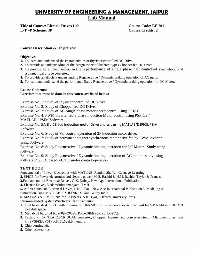
Title of Course: Electric Drives Lab Course Code: EE 791L-T –P Scheme: 3P Course Credits: 2
Course Description & Objectives:
Objectives:1. To learn and understand the characteristics of thysistor controlled DC Drive.2. To provide an understanding of the design aspectof different types Chopper fed DC Drive.3. To provide an efficient understanding ofperformance of single phase half controlled symmetrical and
asymmetrical bridge converter.4. To provide an efficient understanding Regenerative / Dynamic braking operation of AC motor.5. To learn and understand the performance Study Regenerative / Dynamic braking operation for DC Motor.
Course Contents:Exercises that must be done in this course are listed below:
Exercise No. 1: Study of thysistor controlled DC Drive.Exercise No. 2: Study of Chopper fed DC Drive.Exercise No. 3: Study of AC Single phase motor-speed control using TRIAC.Exercise No. 4: PWM Inverter fed 3 phase Induction Motor control using PSPICE /MATLAB / PSIM Software.Exercise No. 5:VSI / CSI fed Induction motor Drive analysis using MATLAB/DSPICE/PSIMSoftware.Exercise No. 6: Study of V/f control operation of 3F induction motor drive.Exercise No. 7: Study of permanent magnet synchronous motor drive fed by PWM Inverterusing Software.Exercise No. 8: Study Regenerative / Dynamic braking operation for DC Motor - Study usingsoftware.Exercise No. 9: Study Regenerative / Dynamic braking operation of AC motor - study usingsoftware.PC/PLC based AC/DC motor control operation.
TEXT BOOK:Fundamental of Power Electronics with MATLAB, Randall Shaffer, Cengage Learning.2. SPICE for Power electronics and electric power, M.H. Rashid & H.M. Rashid, Taylor & Francis.3.Fundamental of Electrical Drives, G.K. Dubey, New Age International Publication.4. Electric Drives, VedamSubrahmanyam, TMH5. A first course on Electrical Drives, S.K. Pillai, , New Age International Publication.5. Modeling &Simulation using MATLAB-SIMILINK , S. Jain, Wiley India6. MATLAB & SIMULINK for Engineers, A.K. Tyagi, Oxford University Press.Recommended Systems/Software Requirements:1. Intel based desktop PC with minimum of 166 MHZ or faster processor with at least 64 MB RAM and 100 MB
free disk space.2. Matlab 32 bit or 64 bit 2009a/2009b. PowerSIM(PSM) 8, DSPICE3. Testing kit for TRAIC,SCR,DUAL converter, Chopper, Inverter and converter circuit, Microcontroller train
kit(PV59RD2V51),uc8051,128kb memory.4. Chip burning kit.5. Other accessories.
UNIVERSITY OF ENGINEERING & MANAGEMENT, JAIPURLab Manual
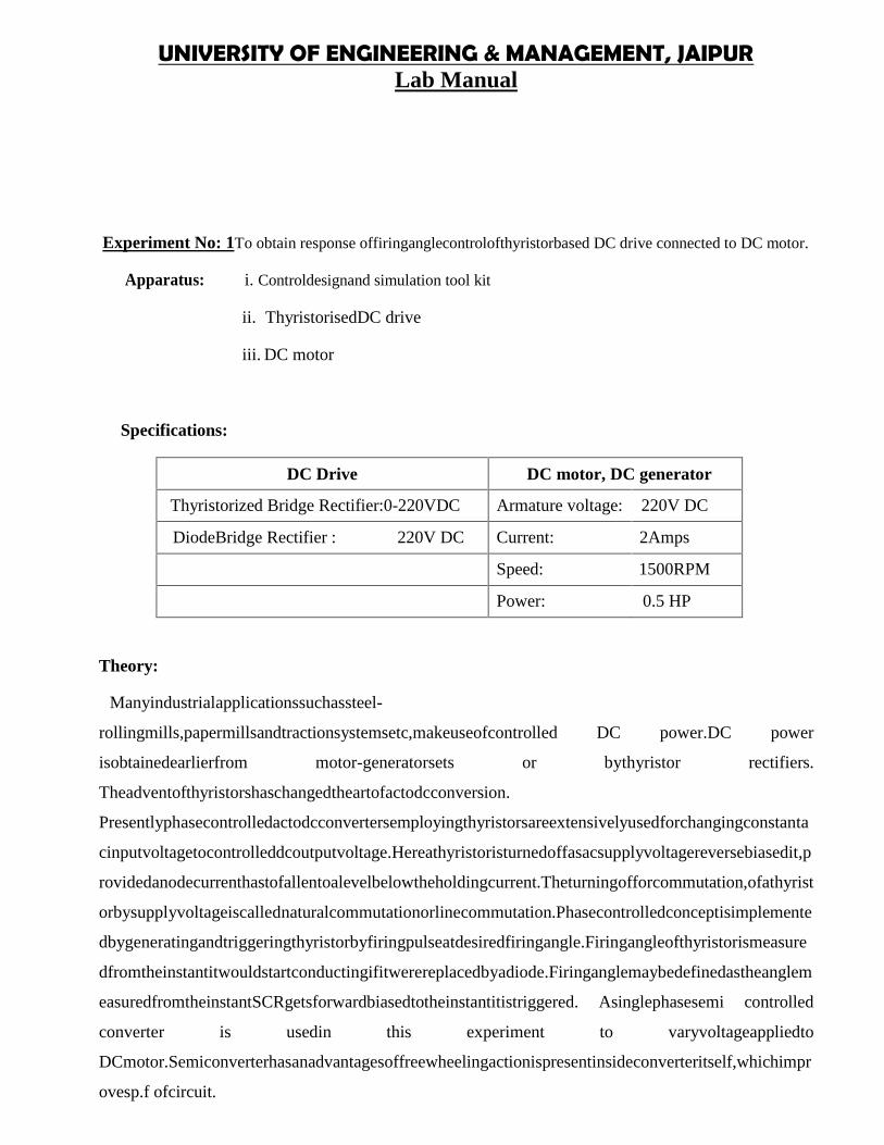
Experiment No: 1To obtain response offiringanglecontrolofthyristorbased DC drive connected to DC motor.
Apparatus: i. Controldesignand simulation tool kit
ii. ThyristorisedDC drive
iii. DC motor
Specifications:
DC Drive DC motor, DC generator
Thyristorized Bridge Rectifier:0-220VDC Armature voltage: 220V DC
DiodeBridge Rectifier : 220V DC Current: 2Amps
Speed: 1500RPM
Power: 0.5 HP
Theory:
Manyindustrialapplicationssuchassteel-
rollingmills,papermillsandtractionsystemsetc,makeuseofcontrolled DC power.DC power
isobtainedearlierfrom motor-generatorsets or bythyristor rectifiers.
Theadventofthyristorshaschangedtheartofactodcconversion.
Presentlyphasecontrolledactodcconvertersemployingthyristorsareextensivelyusedforchangingconstanta
cinputvoltagetocontrolleddcoutputvoltage.Hereathyristoristurnedoffasacsupplyvoltagereversebiasedit,p
rovidedanodecurrenthastofallentoalevelbelowtheholdingcurrent.Theturningofforcommutation,ofathyrist
orbysupplyvoltageiscallednaturalcommutationorlinecommutation.Phasecontrolledconceptisimplemente
dbygeneratingandtriggeringthyristorbyfiringpulseatdesiredfiringangle.Firingangleofthyristorismeasure
dfromtheinstantitwouldstartconductingifitwerereplacedbyadiode.Firinganglemaybedefinedastheanglem
easuredfromtheinstantSCRgetsforwardbiasedtotheinstantitistriggered. Asinglephasesemi controlled
converter is usedin this experiment to varyvoltageappliedto
DCmotor.Semiconverterhasanadvantagesoffreewheelingactionispresentinsideconverteritself,whichimpr
ovesp.f ofcircuit.
UNIVERSITY OF ENGINEERING & MANAGEMENT, JAIPURLab Manual
UNIVERSITY OF ENGINEERING & MANAGEMENT, JAIPURLab Manual
Exercise No. 2: Study of Chopper fed DC Drive.
Aim: Study the characteristics of DC motor fed with DC Chopper
UNIVERSITY OF ENGINEERING & MANAGEMENT, JAIPURLab Manual
Exercise No. 2: Study of Chopper fed DC Drive.
Aim: Study the characteristics of DC motor fed with DC Chopper
UNIVERSITY OF ENGINEERING & MANAGEMENT, JAIPURLab Manual
Exercise No. 2: Study of Chopper fed DC Drive.
Aim: Study the characteristics of DC motor fed with DC Chopper
UNIVERSITY OF ENGINEERING & MANAGEMENT, JAIPURLab Manual
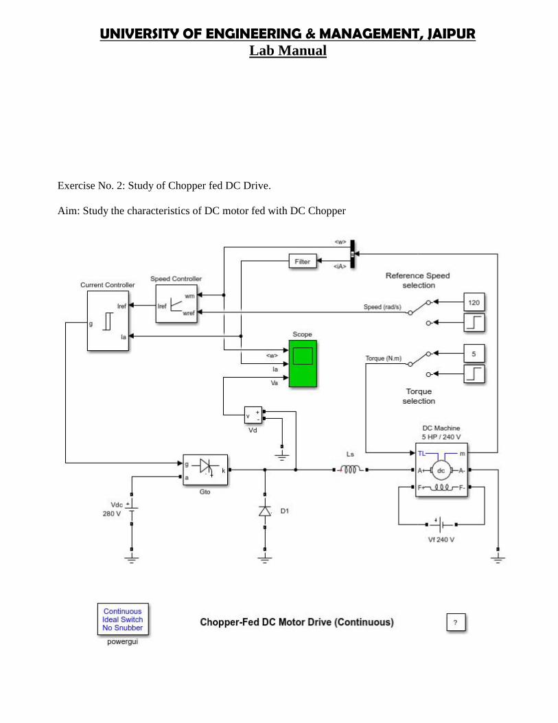
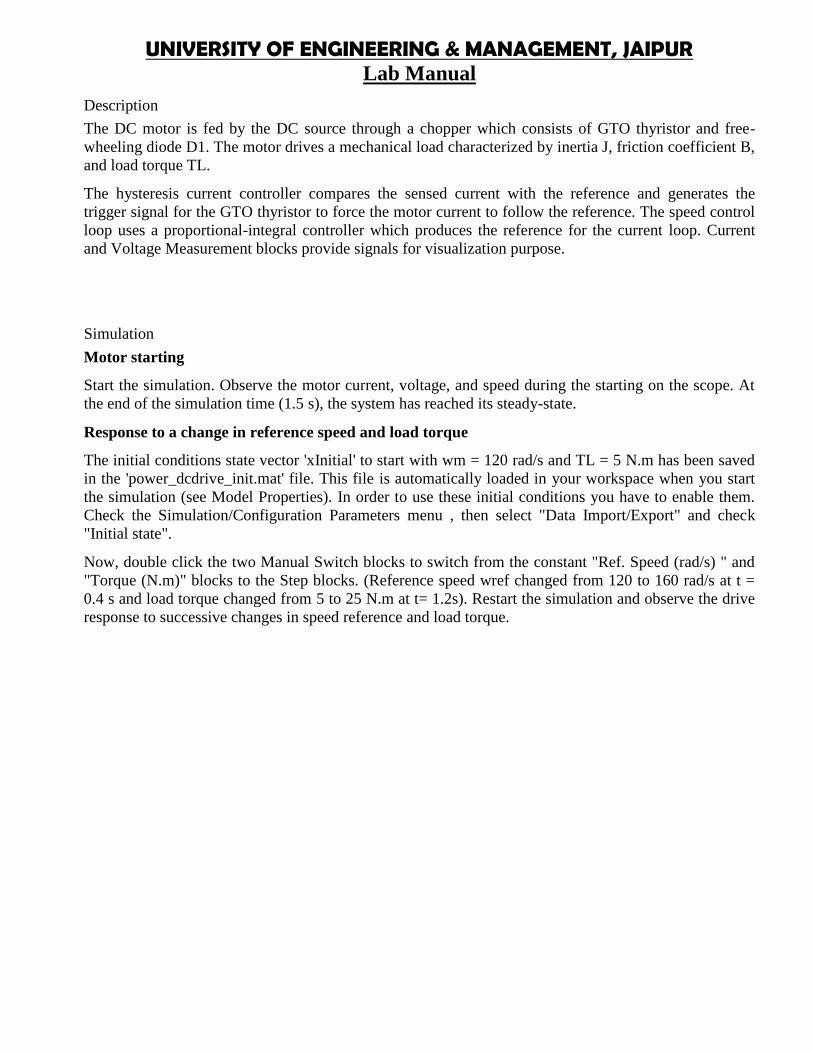
Description
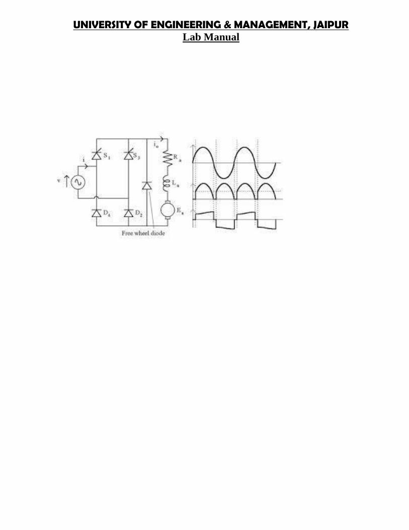
The DC motor is fed by the DC source through a chopper which consists of GTO thyristor and free-wheeling diode D1. The motor drives a mechanical load characterized by inertia J, friction coefficient B,and load torque TL.
The hysteresis current controller compares the sensed current with the reference and generates thetrigger signal for the GTO thyristor to force the motor current to follow the reference. The speed controlloop uses a proportional-integral controller which produces the reference for the current loop. Currentand Voltage Measurement blocks provide signals for visualization purpose.
Simulation
Motor starting
Start the simulation. Observe the motor current, voltage, and speed during the starting on the scope. Atthe end of the simulation time (1.5 s), the system has reached its steady-state.
Response to a change in reference speed and load torque
The initial conditions state vector 'xInitial' to start with wm = 120 rad/s and TL = 5 N.m has been savedin the 'power_dcdrive_init.mat' file. This file is automatically loaded in your workspace when you startthe simulation (see Model Properties). In order to use these initial conditions you have to enable them.Check the Simulation/Configuration Parameters menu , then select "Data Import/Export" and check"Initial state".
Now, double click the two Manual Switch blocks to switch from the constant "Ref. Speed (rad/s) " and"Torque (N.m)" blocks to the Step blocks. (Reference speed wref changed from 120 to 160 rad/s at t =0.4 s and load torque changed from 5 to 25 N.m at t= 1.2s). Restart the simulation and observe the driveresponse to successive changes in speed reference and load torque.
UNIVERSITY OF ENGINEERING & MANAGEMENT, JAIPURLab Manual
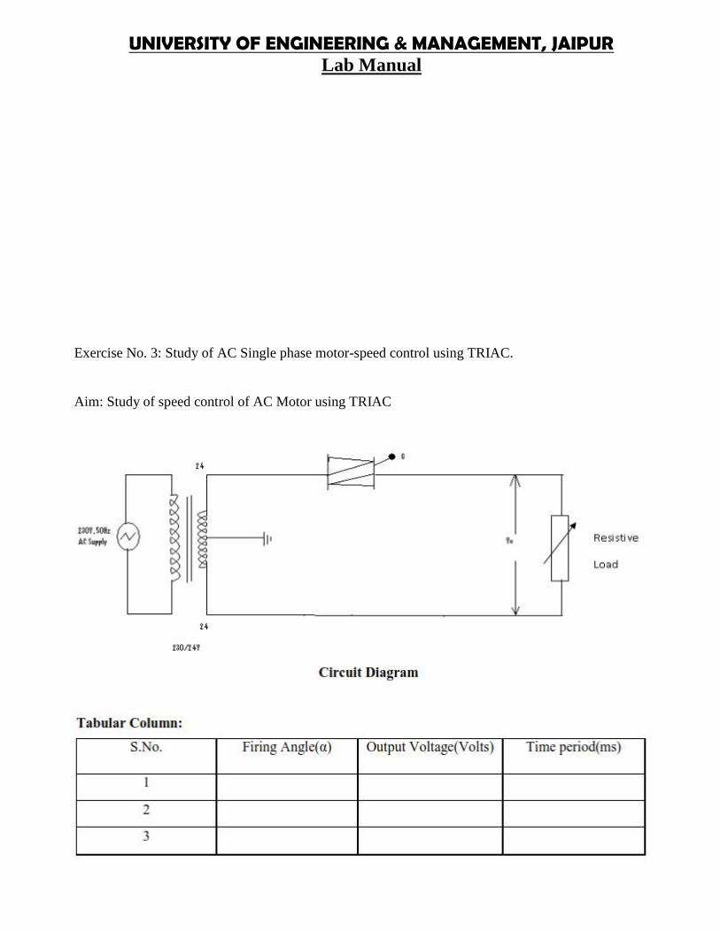
Exercise No. 3: Study of AC Single phase motor-speed control using TRIAC.
Aim: Study of speed control of AC Motor using TRIAC
UNIVERSITY OF ENGINEERING & MANAGEMENT, JAIPURLab Manual
Exercise No. 4: PWM Inverter fed 3 phase Induction Motor control using PSPICE /MATLAB / PSIM Software.
Aim: To study the six step Induction Motor drive using MATLAB
Introduction
The Six-Step VSI Induction Motor Drive block represents a classical open-loop Volts/Hz control, six-step or quasi-square wave drive for induction motors. The block obtains the stator supply frequencyfrom the speed reference (neglecting the slip frequency). This frequency is used to compute the statorflux position necessary to generate the six-step pulses for the three-phase inverter. The block obtains thereference DC bus voltage, or stator input voltage, based on the Volts/Hz control, or constant stator fluxstrategy.
The main advantage of this drive compared to other scalar-controlled and vector-controlled drives is itsimplementation simplicity. However, as with most scalar-controlled drives, the dynamic response of thisdrive is slow due to the inherent coupling effect between the torque and flux that is present in themachine. In addition, this drive tends to be more unstable to change in motor speed compared to closed-loop speed-controlled drives.
UNIVERSITY OF ENGINEERING & MANAGEMENT, JAIPURLab Manual
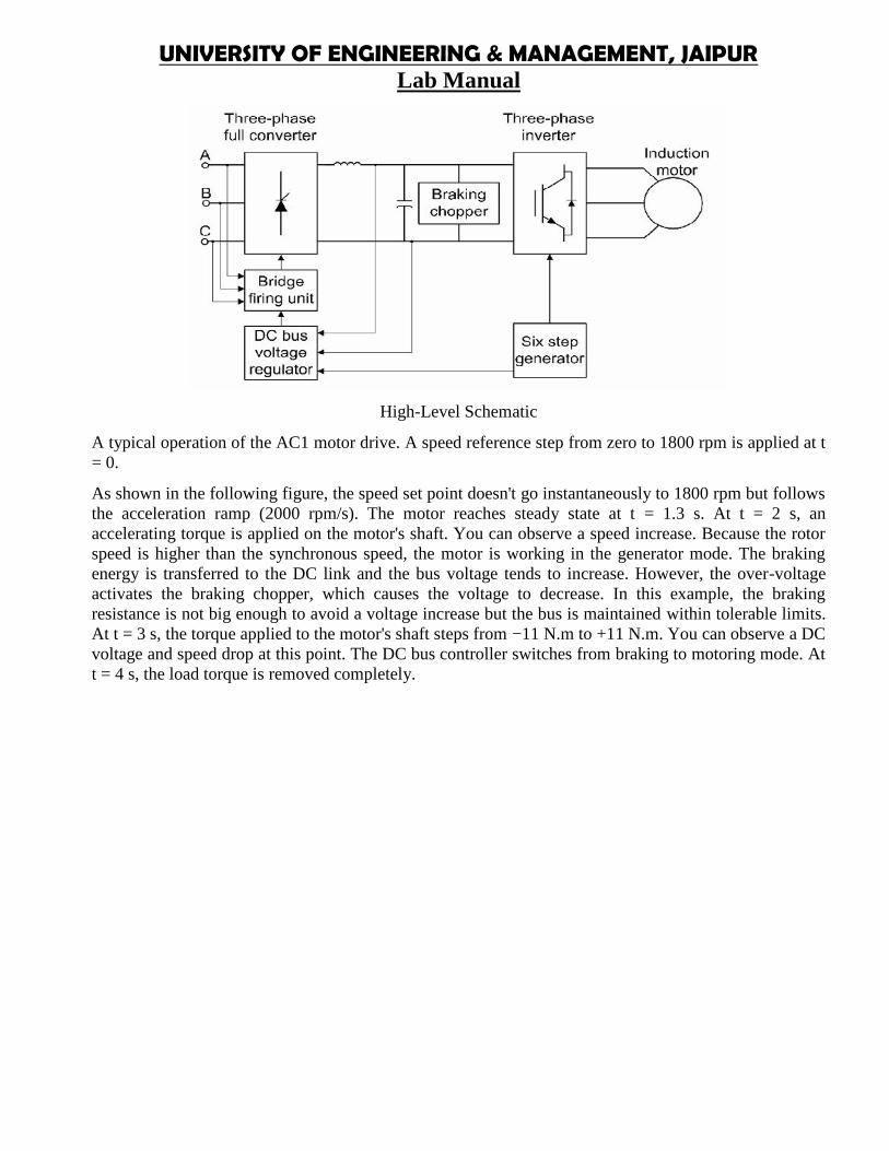
High-Level Schematic
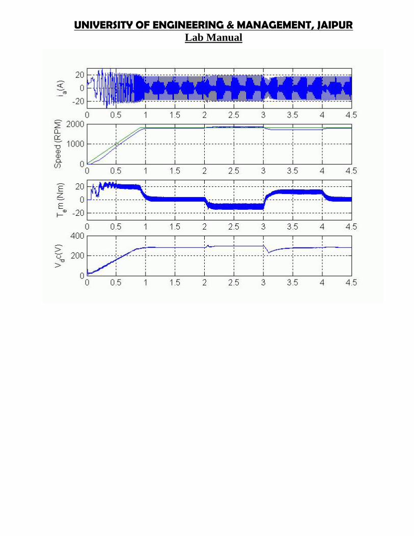
A typical operation of the AC1 motor drive. A speed reference step from zero to 1800 rpm is applied at t= 0.
As shown in the following figure, the speed set point doesn't go instantaneously to 1800 rpm but followsthe acceleration ramp (2000 rpm/s). The motor reaches steady state at t = 1.3 s. At t = 2 s, anaccelerating torque is applied on the motor's shaft. You can observe a speed increase. Because the rotorspeed is higher than the synchronous speed, the motor is working in the generator mode. The brakingenergy is transferred to the DC link and the bus voltage tends to increase. However, the over-voltageactivates the braking chopper, which causes the voltage to decrease. In this example, the brakingresistance is not big enough to avoid a voltage increase but the bus is maintained within tolerable limits.At t = 3 s, the torque applied to the motor's shaft steps from −11 N.m to +11 N.m. You can observe a DCvoltage and speed drop at this point. The DC bus controller switches from braking to motoring mode. Att = 4 s, the load torque is removed completely.
UNIVERSITY OF ENGINEERING & MANAGEMENT, JAIPURLab Manual
UNIVERSITY OF ENGINEERING & MANAGEMENT, JAIPURLab Manual
Exercise No. 5:VSI / CSI fed Induction motor Drive analysis using MATLAB/DSPICE/PSIMSoftware.
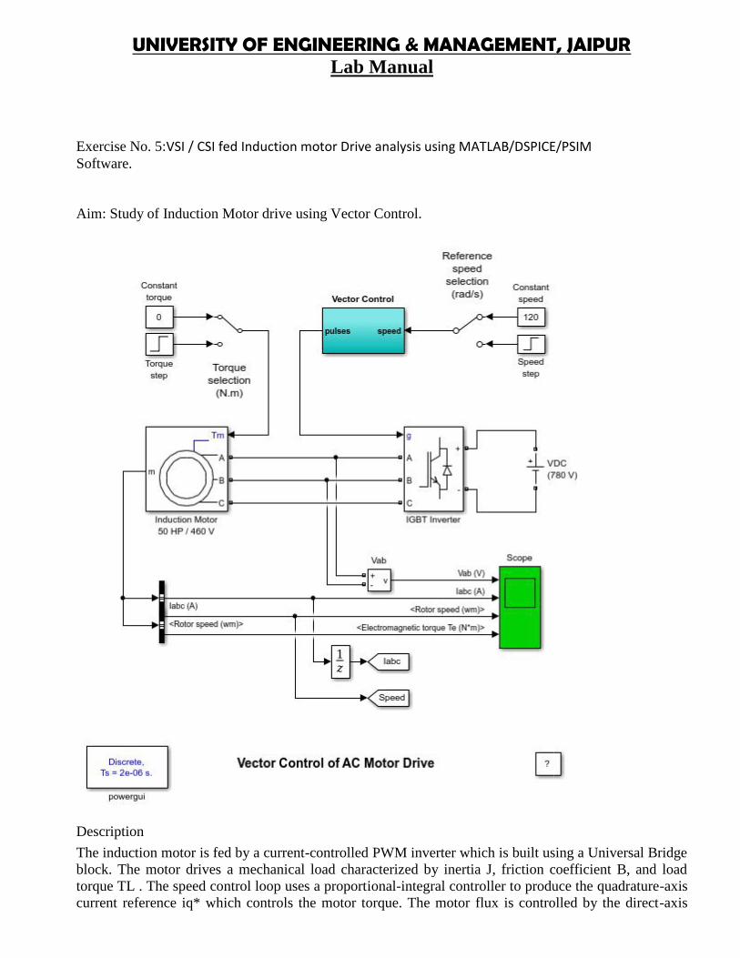
Aim: Study of Induction Motor drive using Vector Control.
Description
The induction motor is fed by a current-controlled PWM inverter which is built using a Universal Bridgeblock. The motor drives a mechanical load characterized by inertia J, friction coefficient B, and loadtorque TL . The speed control loop uses a proportional-integral controller to produce the quadrature-axiscurrent reference iq* which controls the motor torque. The motor flux is controlled by the direct-axis
UNIVERSITY OF ENGINEERING & MANAGEMENT, JAIPURLab Manual
Exercise No. 5:VSI / CSI fed Induction motor Drive analysis using MATLAB/DSPICE/PSIMSoftware.
Aim: Study of Induction Motor drive using Vector Control.
Description
The induction motor is fed by a current-controlled PWM inverter which is built using a Universal Bridgeblock. The motor drives a mechanical load characterized by inertia J, friction coefficient B, and loadtorque TL . The speed control loop uses a proportional-integral controller to produce the quadrature-axiscurrent reference iq* which controls the motor torque. The motor flux is controlled by the direct-axis
UNIVERSITY OF ENGINEERING & MANAGEMENT, JAIPURLab Manual
current reference id*. Block DQ-ABC is used to convert id* and iq* into current references ia*, ib*, andic* for the current regulator. Current and Voltage Measurement blocks provide signals for visualizationpurpose. Motor current, speed, and torque signals are available at the output of the 'AsynchronousMachine' block.
Exercise No. 6: Study of V/f control operation of 3F induction motor drive.
Aim: Speed control of 3 phase Induction Motor using V/f method.
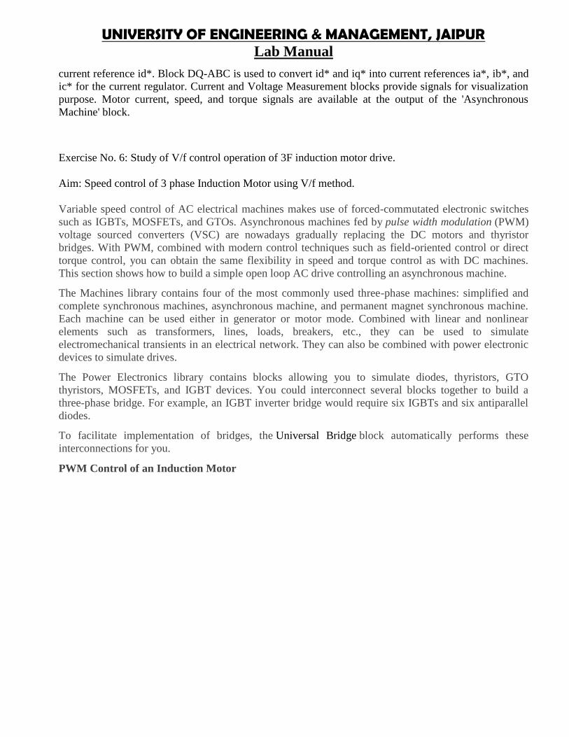
Variable speed control of AC electrical machines makes use of forced-commutated electronic switchessuch as IGBTs, MOSFETs, and GTOs. Asynchronous machines fed by pulse width modulation (PWM)voltage sourced converters (VSC) are nowadays gradually replacing the DC motors and thyristorbridges. With PWM, combined with modern control techniques such as field-oriented control or directtorque control, you can obtain the same flexibility in speed and torque control as with DC machines.This section shows how to build a simple open loop AC drive controlling an asynchronous machine.
The Machines library contains four of the most commonly used three-phase machines: simplified andcomplete synchronous machines, asynchronous machine, and permanent magnet synchronous machine.Each machine can be used either in generator or motor mode. Combined with linear and nonlinearelements such as transformers, lines, loads, breakers, etc., they can be used to simulateelectromechanical transients in an electrical network. They can also be combined with power electronicdevices to simulate drives.
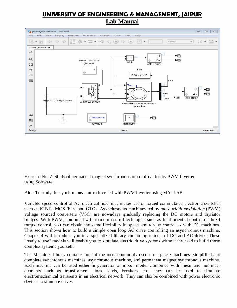
The Power Electronics library contains blocks allowing you to simulate diodes, thyristors, GTOthyristors, MOSFETs, and IGBT devices. You could interconnect several blocks together to build athree-phase bridge. For example, an IGBT inverter bridge would require six IGBTs and six antiparalleldiodes.
To facilitate implementation of bridges, the Universal Bridge block automatically performs theseinterconnections for you.
PWM Control of an Induction Motor
UNIVERSITY OF ENGINEERING & MANAGEMENT, JAIPURLab Manual
Exercise No. 7: Study of permanent magnet synchronous motor drive fed by PWM Inverterusing Software.
Aim: To study the synchronous motor drive fed with PWM Inverter using MATLAB
Variable speed control of AC electrical machines makes use of forced-commutated electronic switchessuch as IGBTs, MOSFETs, and GTOs. Asynchronous machines fed by pulse width modulation (PWM)voltage sourced converters (VSC) are nowadays gradually replacing the DC motors and thyristorbridges. With PWM, combined with modern control techniques such as field-oriented control or directtorque control, you can obtain the same flexibility in speed and torque control as with DC machines.This section shows how to build a simple open loop AC drive controlling an asynchronous machine.Chapter 4 will introduce you to a specialized library containing models of DC and AC drives. These"ready to use" models will enable you to simulate electric drive systems without the need to build thosecomplex systems yourself.
The Machines library contains four of the most commonly used three-phase machines: simplified andcomplete synchronous machines, asynchronous machine, and permanent magnet synchronous machine.Each machine can be used either in generator or motor mode. Combined with linear and nonlinearelements such as transformers, lines, loads, breakers, etc., they can be used to simulateelectromechanical transients in an electrical network. They can also be combined with power electronicdevices to simulate drives.
UNIVERSITY OF ENGINEERING & MANAGEMENT, JAIPURLab Manual
The Power Electronics library contains blocks allowing you to simulate diodes, thyristors, GTOthyristors, MOSFETs, and IGBT devices. You could interconnect several blocks together to build athree-phase bridge. For example, an IGBT inverter bridge would require six IGBTs and six antiparalleldiodes.
To facilitate implementation of bridges, the Universal Bridge block automatically performs theseinterconnections for you.
PWM Control of an Induction Motor
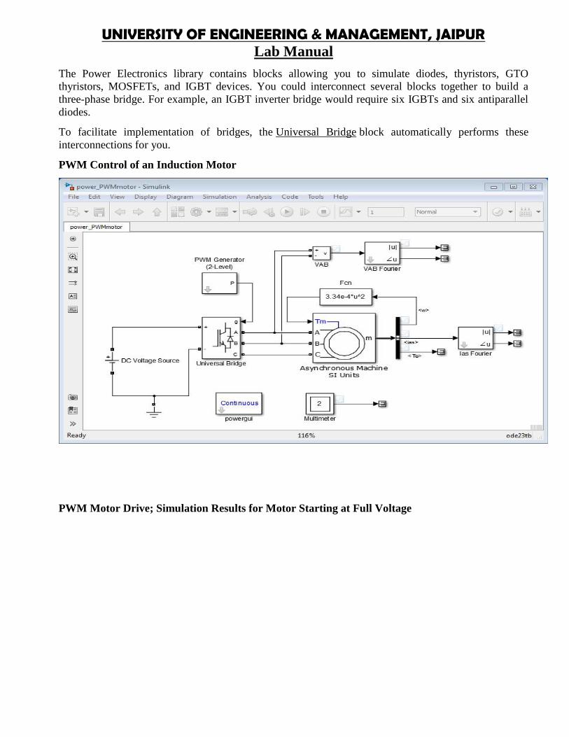
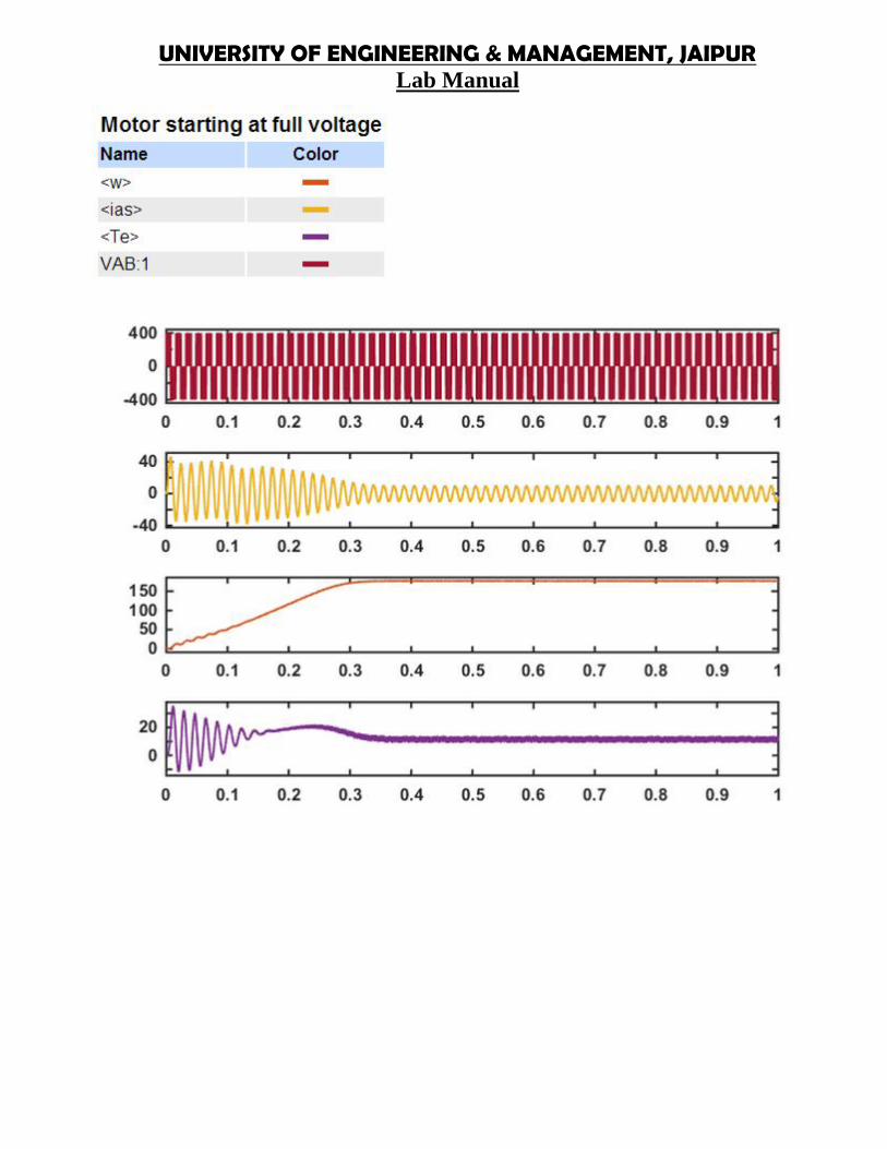
PWM Motor Drive; Simulation Results for Motor Starting at Full Voltage
UNIVERSITY OF ENGINEERING & MANAGEMENT, JAIPURLab Manual
UNIVERSITY OF ENGINEERING & MANAGEMENT, JAIPURLab Manual
Exercise No. 8: Study Regenerative / Dynamic braking operation for DC Motor - Study usingsoftware.
Aim: Study the DC motor characteristics during regenerative braking using MATLAB
Introduction
In this section, you will learn how to use the DC drive models of the Electric Drives library. First, wewill specify the types of motor, converters, and controllers used in the seven DC drive models of thelibrary, designated DC1 to DC7. These seven models are based on the DC brush motor in the ElectricDrives library. As in any electric motor, the DC brush motor has two main parts, the stator (fixed) partand the rotor (movable) part. The DC brush motor also has two types of windings, the excitation or fieldwinding and the armature winding. As its name implies, the field winding is used to produce a magneticexcitation field in the motor whereas the armature coils carry the induced motor current. Since the timeconstant (L/R) of the armature circuit is much smaller than that of the field winding, controlling speed bychanging armature voltage is quicker than changing the field voltage. Therefore the excitation field isfed from a constant DC voltage source while the armature windings are fed by a variable DC source. Thelatter source is produced by a phase-controlled thyristor converter for the DC1 to DC4 models and by atransistor chopper for the DC5, DC6, and DC7 models. The thyristor converter is fed by a single-phaseAC source in the cases of DC1 and DC2 and by a three-phase AC source in the cases of DC3 and DC4.Finally, the seven DC models can work in various sets of quadrants. All these possibilities aresummarized in the following table.
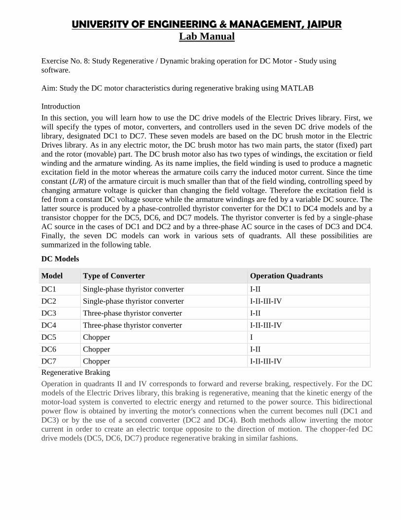
DC Models
Model Type of Converter Operation Quadrants
DC1 Single-phase thyristor converter I-II
DC2 Single-phase thyristor converter I-II-III-IV
DC3 Three-phase thyristor converter I-II
DC4 Three-phase thyristor converter I-II-III-IV
DC5 Chopper I
DC6 Chopper I-II
DC7 Chopper I-II-III-IV
Regenerative Braking
Operation in quadrants II and IV corresponds to forward and reverse braking, respectively. For the DCmodels of the Electric Drives library, this braking is regenerative, meaning that the kinetic energy of themotor-load system is converted to electric energy and returned to the power source. This bidirectionalpower flow is obtained by inverting the motor's connections when the current becomes null (DC1 andDC3) or by the use of a second converter (DC2 and DC4). Both methods allow inverting the motorcurrent in order to create an electric torque opposite to the direction of motion. The chopper-fed DCdrive models (DC5, DC6, DC7) produce regenerative braking in similar fashions.
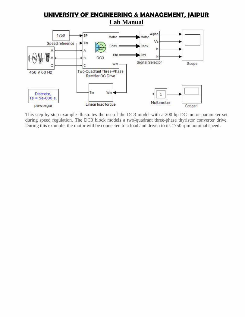
UNIVERSITY OF ENGINEERING & MANAGEMENT, JAIPURLab Manual
This step-by-step example illustrates the use of the DC3 model with a 200 hp DC motor parameter setduring speed regulation. The DC3 block models a two-quadrant three-phase thyristor converter drive.During this example, the motor will be connected to a load and driven to its 1750 rpm nominal speed.
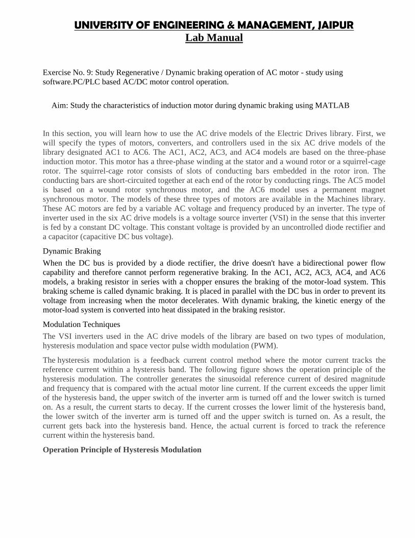
UNIVERSITY OF ENGINEERING & MANAGEMENT, JAIPURLab Manual
Exercise No. 9: Study Regenerative / Dynamic braking operation of AC motor - study usingsoftware.PC/PLC based AC/DC motor control operation.
Aim: Study the characteristics of induction motor during dynamic braking using MATLAB
In this section, you will learn how to use the AC drive models of the Electric Drives library. First, wewill specify the types of motors, converters, and controllers used in the six AC drive models of thelibrary designated AC1 to AC6. The AC1, AC2, AC3, and AC4 models are based on the three-phaseinduction motor. This motor has a three-phase winding at the stator and a wound rotor or a squirrel-cagerotor. The squirrel-cage rotor consists of slots of conducting bars embedded in the rotor iron. Theconducting bars are short-circuited together at each end of the rotor by conducting rings. The AC5 modelis based on a wound rotor synchronous motor, and the AC6 model uses a permanent magnetsynchronous motor. The models of these three types of motors are available in the Machines library.These AC motors are fed by a variable AC voltage and frequency produced by an inverter. The type ofinverter used in the six AC drive models is a voltage source inverter (VSI) in the sense that this inverteris fed by a constant DC voltage. This constant voltage is provided by an uncontrolled diode rectifier anda capacitor (capacitive DC bus voltage).
Dynamic Braking
When the DC bus is provided by a diode rectifier, the drive doesn't have a bidirectional power flowcapability and therefore cannot perform regenerative braking. In the AC1, AC2, AC3, AC4, and AC6models, a braking resistor in series with a chopper ensures the braking of the motor-load system. Thisbraking scheme is called dynamic braking. It is placed in parallel with the DC bus in order to prevent itsvoltage from increasing when the motor decelerates. With dynamic braking, the kinetic energy of themotor-load system is converted into heat dissipated in the braking resistor.
Modulation Techniques
The VSI inverters used in the AC drive models of the library are based on two types of modulation,hysteresis modulation and space vector pulse width modulation (PWM).
The hysteresis modulation is a feedback current control method where the motor current tracks thereference current within a hysteresis band. The following figure shows the operation principle of thehysteresis modulation. The controller generates the sinusoidal reference current of desired magnitudeand frequency that is compared with the actual motor line current. If the current exceeds the upper limitof the hysteresis band, the upper switch of the inverter arm is turned off and the lower switch is turnedon. As a result, the current starts to decay. If the current crosses the lower limit of the hysteresis band,the lower switch of the inverter arm is turned off and the upper switch is turned on. As a result, thecurrent gets back into the hysteresis band. Hence, the actual current is forced to track the referencecurrent within the hysteresis band.
Operation Principle of Hysteresis Modulation
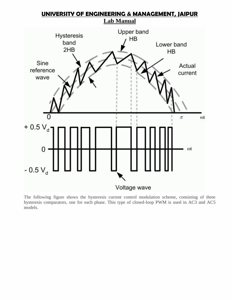
UNIVERSITY OF ENGINEERING & MANAGEMENT, JAIPURLab Manual
The following figure shows the hysteresis current control modulation scheme, consisting of threehysteresis comparators, one for each phase. This type of closed-loop PWM is used in AC3 and AC5models.

UNIVERSITY OF ENGINEERING & MANAGEMENT, JAIPURLab Manual
UNIVERSITY OF ENGINEERING & MANAGEMENT, JAIPURLab Manual
Title of Course: Electric System Design LabCourse Code: EE 795L-T-P scheme: 0-0-3 Course Credit: 2
Objectives:1. To introduce the student fundamentals of Electrical System design and layout.2. To learn the basics of line diagram.3. To assimilate the design criteria and use it for a large scale design.
Learning Outcomes: The students will have a detailed knowledge of the concepts Electrical System andtheir co-ordination.
Course Contents:Exercises that must be done in this course are listed below:Exercise No.1:Study of residential house wiring using switches, fuse, lamps and energy meter.Exercise No. 2: Study of different types of wiringExercise No. 3: Study of fluorescent lamp wiring.
Exercise No. 4: Measurement of electrical quantities.Exercise No. 5: Study of ETAP.
Text Book:1. Electric Power Distribution Handbook, G Ramamurthy, University Press, 2nd Edition.
Recommended Systems/Apparatus Requirements:Laboratory Kits, Multimeters, Connecting wires, Watt Meters, PC.
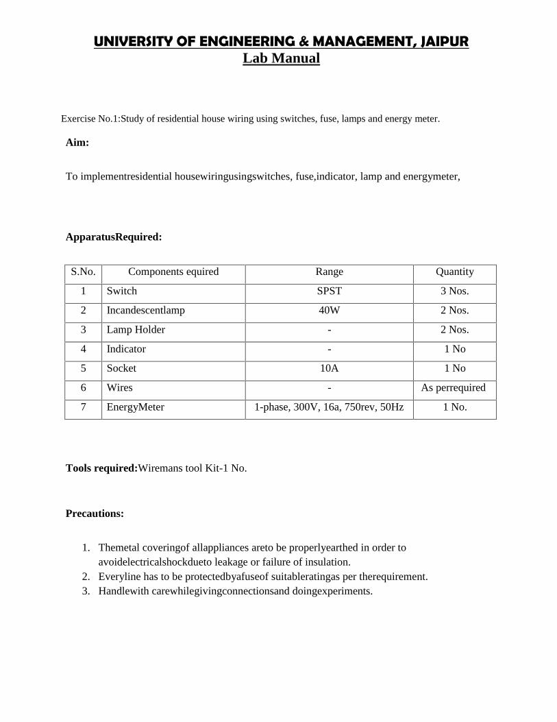
UNIVERSITY OF ENGINEERING & MANAGEMENT, JAIPURLab Manual
Exercise No.1:Study of residential house wiring using switches, fuse, lamps and energy meter.
Aim:
To implementresidential housewiringusingswitches, fuse,indicator, lamp and energymeter,
ApparatusRequired:
S.No. Components equired Range Quantity
1 Switch SPST 3 Nos.
2 Incandescentlamp 40W 2 Nos.
3 Lamp Holder - 2 Nos.
4 Indicator - 1 No
5 Socket 10A 1 No
6 Wires - As perrequired
7 EnergyMeter 1-phase, 300V, 16a, 750rev, 50Hz 1 No.
Tools required:Wiremans tool Kit-1 No.
Precautions:
1. Themetal coveringof allappliances areto be properlyearthed in order toavoidelectricalshockdueto leakage or failure of insulation.
2. Everyline has to be protectedbyafuseof suitableratingas per therequirement.3. Handlewith carewhilegivingconnectionsand doingexperiments.
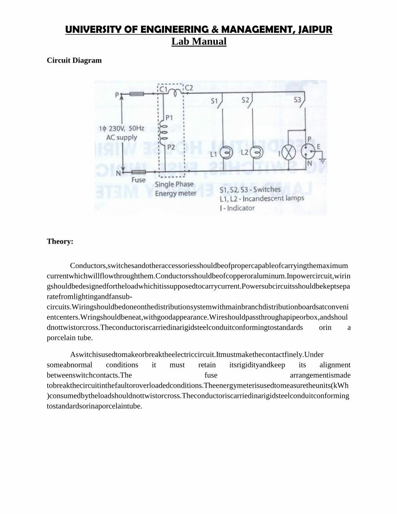
UNIVERSITY OF ENGINEERING & MANAGEMENT, JAIPURLab Manual
Circuit Diagram
Theory:
Conductors,switchesandotheraccessoriesshouldbeofpropercapableofcarryingthemaximumcurrentwhichwillflowthroughthem.Conductorsshouldbeofcopperoraluminum.Inpowercircuit,wiringshouldbedesignedfortheloadwhichitissupposedtocarrycurrent.Powersubcircuitsshouldbekeptseparatefromlightingandfansub-circuits.Wiringshouldbedoneonthedistributionsystemwithmainbranchdistributionboardsatconvenientcenters.Wringshouldbeneat,withgoodappearance.Wireshouldpassthroughapipeorbox,andshouldnottwistorcross.Theconductoriscarriedinarigidsteelconduitconformingtostandards orin aporcelain tube.
Aswitchisusedtomakeorbreaktheelectriccircuit.Itmustmakethecontactfinely.Undersomeabnormal conditions it must retain itsrigidityandkeep its alignmentbetweenswitchcontacts.The fuse arrangementismadetobreakthecircuitinthefaultoroverloadedconditions.Theenergymeterisusedtomeasuretheunits(kWh)consumedbytheloadshouldnottwistorcross.Theconductoriscarriedinarigidsteelconduitconformingtostandardsorinaporcelaintube.
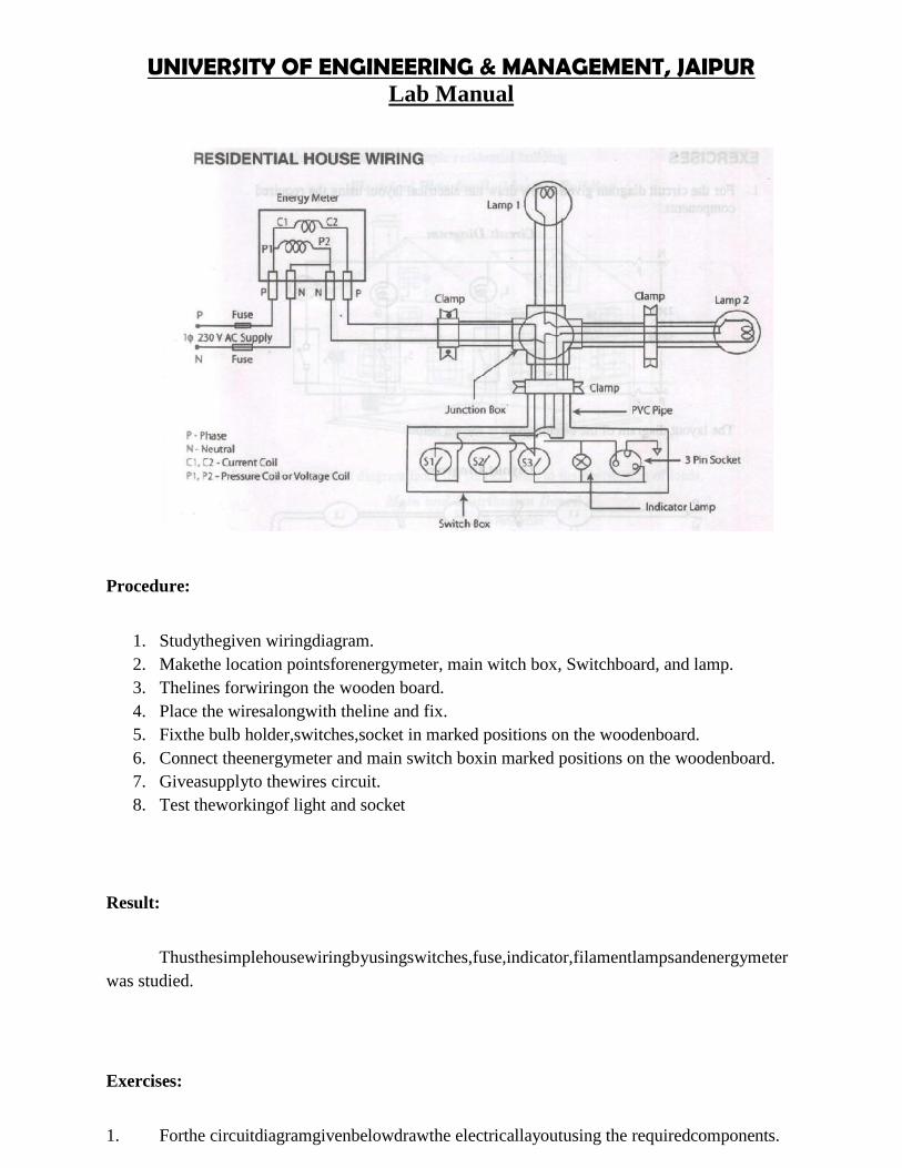
UNIVERSITY OF ENGINEERING & MANAGEMENT, JAIPURLab Manual
Procedure:
1. Studythegiven wiringdiagram.2. Makethe location pointsforenergymeter, main witch box, Switchboard, and lamp.3. Thelines forwiringon the wooden board.4. Place the wiresalongwith theline and fix.5. Fixthe bulb holder,switches,socket in marked positions on the woodenboard.6. Connect theenergymeter and main switch boxin marked positions on the woodenboard.7. Giveasupplyto thewires circuit.8. Test theworkingof light and socket
Result:
Thusthesimplehousewiringbyusingswitches,fuse,indicator,filamentlampsandenergymeterwas studied.
Exercises:
1. Forthe circuitdiagramgivenbelowdrawthe electricallayoutusing the requiredcomponents.
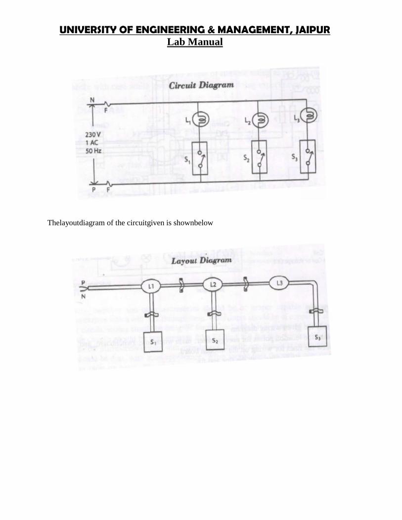
UNIVERSITY OF ENGINEERING & MANAGEMENT, JAIPURLab Manual
Thelayoutdiagram of the circuitgiven is shownbelow
UNIVERSITY OF ENGINEERING & MANAGEMENT, JAIPURLab Manual
Thelayoutdiagram of the circuitgiven is shownbelow
UNIVERSITY OF ENGINEERING & MANAGEMENT, JAIPURLab Manual
Thelayoutdiagram of the circuitgiven is shownbelow
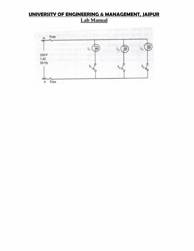
UNIVERSITY OF ENGINEERING & MANAGEMENT, JAIPURLab Manual
UNIVERSITY OF ENGINEERING & MANAGEMENT, JAIPURLab Manual
UNIVERSITY OF ENGINEERING & MANAGEMENT, JAIPURLab Manual
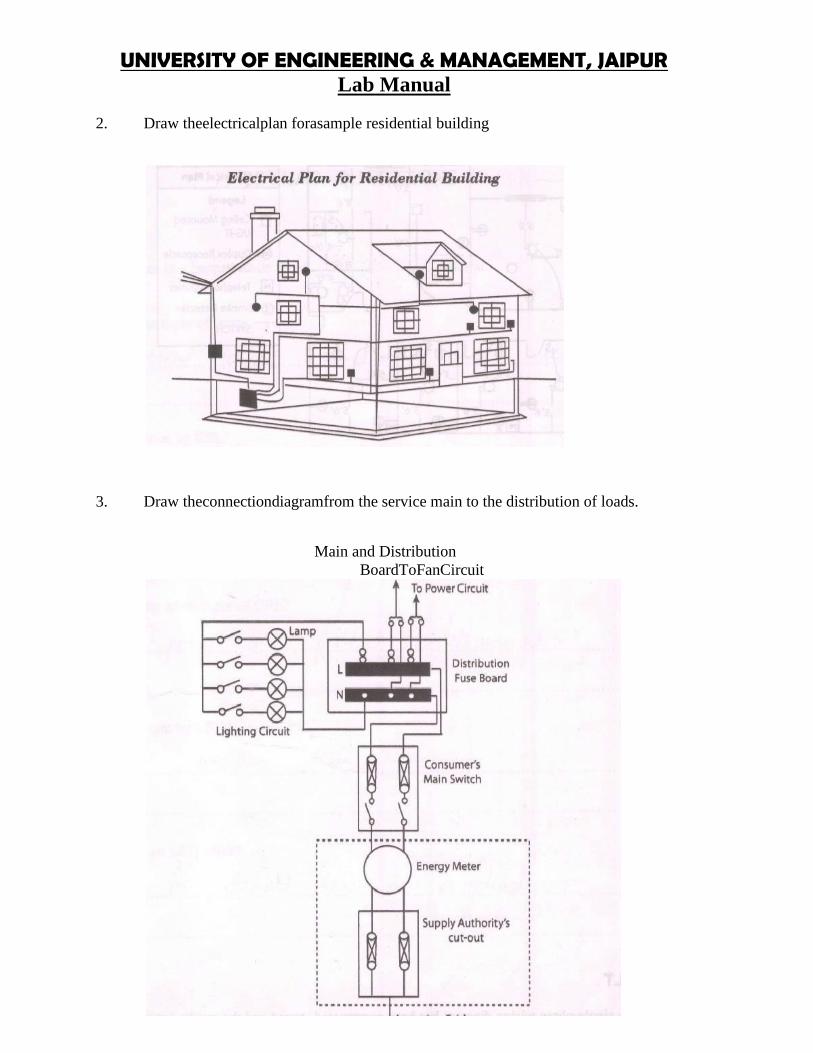
UNIVERSITY OF ENGINEERING & MANAGEMENT, JAIPURLab Manual
2. Draw theelectricalplan forasample residential building
3. Draw theconnectiondiagramfrom the service main to the distribution of loads.
Main and DistributionBoardToFanCircuit
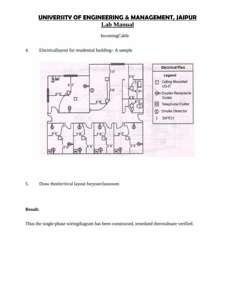
UNIVERSITY OF ENGINEERING & MANAGEMENT, JAIPURLab Manual
IncomingCable
4. Electricallayout for residential building– A sample
5. Draw theelectrical layout foryourclassroom
Result:
Thus the single-phase wiringdiagram has been constructed, testedand theresultsare verified.
UNIVERSITY OF ENGINEERING & MANAGEMENT, JAIPURLab Manual
Exercise No. 2: Study of different types of wiring
Aim:
Tostudydifferenttypesofwiring and to preparethe following wiring:
(i) Staircase wiring(ii) Fluorescentlamp wiring(iii) Corridor wiring
ApparatusRequired:
S.No.
ToolsrequiredFluorescent
Lamp WiringStaircaseWiring Corridor Wiring
1 Fluorescentfitting
lamp with Twowayswitches Switches Screwdriver
2 Joint clips Bulb,Bulbholder Bulb,Bulbholder Hammer3 Wires Clamps Clamps Cuttingpliers4 Screws Screws Screws Line tester5 Switch board Ceilingrose Ceilingrose6 Choke Switch board Switch board7 Switches Connectingwires Connectingwires
Types ofWiring
Therearevarious typesofwiringused in the residential and commercial buildings.Theyare
1. Cleat Wring2. Batten Wiring
(a) PVC Batten Wiring(b) TRS/CTSWiring(c) LeadSheath Wiring
3. CasingCappingWiring(a) Wood CasingCapping Wiring(b) PVC CasingCappingWiring
4. Conduit Wiring(a) Surface Conduit

UNIVERSITY OF ENGINEERING & MANAGEMENT, JAIPURLab Manual
WiringMetal ConduitWiringPVCConduitWiring
(b) Concealed Conduit Wiring
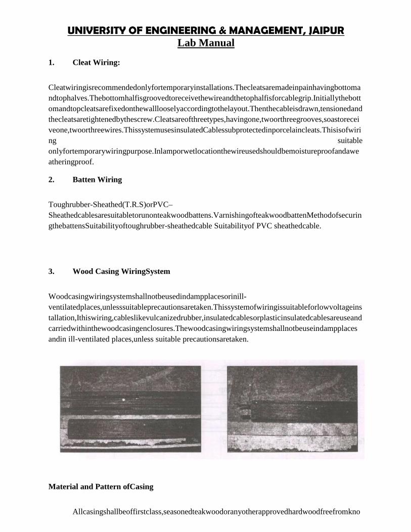
UNIVERSITY OF ENGINEERING & MANAGEMENT, JAIPURLab Manual
1. Cleat Wiring:
Cleatwiringisrecommendedonlyfortemporaryinstallations.Thecleatsaremadeinpainhavingbottomandtophalves.Thebottomhalfisgroovedtoreceivethewireandthetophalfisforcablegrip.Initiallythebottomandtopcleatsarefixedonthewalllooselyaccordingtothelayout.Thenthecableisdrawn,tensionedandthecleatsaretightenedbythescrew.Cleatsareofthreetypes,havingone,twoorthreegrooves,soastoreceiveone,twoorthreewires.ThissystemusesinsulatedCablessubprotectedinporcelaincleats.Thisisofwiring suitableonlyfortemporarywiringpurpose.Inlamporwetlocationthewireusedshouldbemoistureproofandaweatheringproof.
2. Batten Wiring
Toughrubber-Sheathed(T.R.S)orPVC–Sheathedcablesaresuitabletorunonteakwoodbattens.VarnishingofteakwoodbattenMethodofsecuringthebattensSuitabilityoftoughrubber-sheathedcable Suitabilityof PVC sheathedcable.
3. Wood Casing WiringSystem
Woodcasingwiringsystemshallnotbeusedindampplacesorinill-ventilatedplaces,unlesssuitableprecautionsaretaken.Thissystemofwiringissuitableforlowvoltageinstallation,Ithiswiring,cableslikevulcanizedrubber,insulatedcablesorplasticinsulatedcablesareuseandcarriedwithinthewoodcasingenclosures.Thewoodcasingwiringsystemshallnotbeuseindampplacesandin ill-ventilated places,unless suitable precautionsaretaken.
Material and Pattern ofCasing
Allcasingshallbeoffirstclass,seasonedteakwoodoranyotherapprovedhardwoodfreefromkno
UNIVERSITY OF ENGINEERING & MANAGEMENT, JAIPURLab Manual
ts,shakes,sapsorotherdefects,withallthesidesplanedtoasmoothfinish,andallsideswellvarnished,bothinsideandoutsidewithpureshellacvarnish.Thecasingshallhaveagroovedbodywith a beaded or plain-molded cover asdesired.
4. Tough rubber-Sheathed or PVCSheathed Wiring System
Wiringwithtoughrubbersheathedcablesissuitableforlowvoltageinstallationsandshallnotbeusedinplacesexposedtosunandrainnorindampplaces,unlesswiresaresheathedinprotective coveringagainstatmosphereand well protected to withstand dampness.
5. Metal-Sheathed Wiring System
Metal-sheathedwiringsystemissuitablefor1GWvoltageinstallations,andshallnotbeusedinsituationswhereacidsandalkalisarelikelytobepresent.Metal-sheathedwiringmaybeusedinplaces exposedto sun andrainprovided no joint of anydescription is exposed.
6. Conduit WiringSystem
Thisusesaconduitpipeforthemechanicalprotectionofwire.Inthissystemofwiring,wiresarecarriedthroughP.V.Cconduitpipeforgivingconvergingtopipesconduitpipehascertainadvantages likeit ismoisture proofanddurable.
Exercise No. 3: Study of fluorescent lamp wiring.
Aim:
To make connections ofa fluorescentlamp wiringand to studythe accessories of the same.
ApparatusRequired:
S.No. Components Range/Type Quantity1 Fluorescentlamp fixture 4 ft 12 Fluorescentlamp 40W 13 Choke 40W, 230V 14 Starter - 15 Connectingwires - As perrequired
Tools Required :Wiremans tool kit– 1
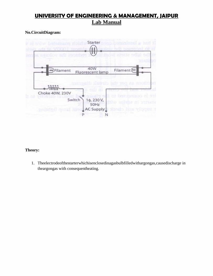
UNIVERSITY OF ENGINEERING & MANAGEMENT, JAIPURLab Manual
No.CircuitDiagram:
Theory:
1. Theelectrodeofthestarterwhichisenclosedinagasbulbfilledwithargongas,causedischarge intheargongas with consequentheating.
UNIVERSITY OF ENGINEERING & MANAGEMENT, JAIPURLab Manual
2. Due toheating,thebimetallicstripbendsandcausesinthestarter toclose.After this,thechoke,the filaments (tube ends) to tube and starter becomesconnected in series.
3. Whenthecurrentflowsthroughthetubeendfilamentstheheatisproduced.Duringtheprocessthedischargeinthestartertubedisappearsandthecontactsinthestartermoveapart.
4. Whensuddenbreakinthecircuitoccurduetomovingapartofstarterterminals,thiscauses ahighvalue ofe.m.f to be induced in thechoke.
5. AccordingtoLenz‟s,thedirectionofinducede.m.finthechokewilltrytoopposesthefall of current in the circuit.
6. Thevoltagethusactingacrossthetubeendswillbehighenoughtocauseadischargetooccur inthegas inside thetube. Thus the startsgivinglight.
7. Thefluorescentlampisalowpressuremercurylampandisalongevacuatedtube.Itcontainsasmallamountofmercuryandargongasat2.5mmpressure.Atthetimeofswitchinginthetubemercuryisintheformofsmalldrops.Therefore,tostartthetube,fillingupofargongasisnecessary.So,inthebeginning,argongasstartsburningattheendsofthetube;themercuryisheatedandcontrolsthecurrentandthetubestartsgivinglight.Ateachendofthetube,thereisatungstenelectrodewhichiscoatedwithfastelectronemittingmaterial.Insideofthetubeiscoatedwithphosphoraccordingtothetype of light.
8. Astarterhelpstostartthestartthetubeandbreakthecircuit.Thechokecoilisalsocalledblast.Ithasalaminatedcoreoverwhichenameledwireiswound.Thefunctionofthechokeistoincreasethevoltagetoalmost1000Vatthetimeofswitchingonthetubeandwhenthetubestartsworking,itreducesthevoltageacrossthetubeandkeepsthe currents constant.
Procedure:
1. Givethe connectionsasper thecircuitdiagram2. Fixthe tubeholderand the choke in thetube.3. Thephase wireis connected to the choke and neutral directlyto thetube.4. Connect the starterin series with the tube.5. Switch on thesupplyandcheck thefluorescent lamp lighting.
Result:
Thus the fluorescentlampcircuit is studiedandassembled.Exercise No. 4: Measurement of electrical quantities.
Aim:
Tomeasuretheelectricalquantities–voltage,current,powerandtocalculatepowerfactorforRLCcircuit.
ApparatusRequired:
S.No. Components Range/Type Quantity

UNIVERSITY OF ENGINEERING & MANAGEMENT, JAIPURLab Manual
1 Voltmeter (0-300)V,MItype 12 Ammeter (0-10)A,MItype 13 Wattmeter 300V, 10A,UPF/LPF 14 Autotransformer 1KVA,230/(0-270)V 15 Resistive, inductive &capacitiveload - 16 Connectingwire - As perrequired
Theory:
Powerinanelectriccircuitcanbemeasuredusingawattmeter.Awattmeterconsistsoftwocoils,namelycurrentcoilandpressurecoilorpotentialcoil.ThecurrentcoilismarkedasMLandpressurecoilismarkedasCV.Thecurrentcoilmeasuresthequantitythatisproportionaltothecurrentinthecircuitandthepressuremeasuresquantitythatisproportionaltovoltageinthecircuit.Anammeterisconnectedinseriestothewattmetertomeasurethecurrent.Avoltmeterisconnectedinparalleltowattmetertomeasurevoltage.Thepowerfactorofthecircuitiscalculated usingtherelation givenbelow:
Formulae:
Actualpower = OR xmultiplicationfactor
Apparent power = VIwatts
Powerfactor, Cos = (Actual power)/ (Apparent power)
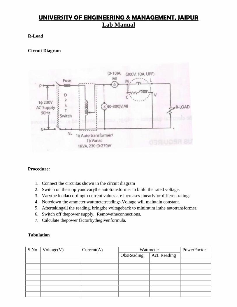
UNIVERSITY OF ENGINEERING & MANAGEMENT, JAIPURLab Manual
R-Load
Circuit Diagram
Procedure:
1. Connect the circuitas shown in the circuit diagram2. Switch on thesupplyandvarythe autotransformer to build the rated voltage.3. Varythe loadaccordingto current values are increases linearlyfor differentratings.4. Notedown the ammeter,wattmeterreadings.Voltage will maintain constant.5. Aftertakingall the reading, bringthe voltageback to minimum inthe autotransformer.6. Switch off thepower supply. Removetheconnections.7. Calculate thepower factorbythegivenformula.
Tabulation
S.No. Voltage(V) Current(A) Wattmeter PowerFactorObsReading Act. Reading

UNIVERSITY OF ENGINEERING & MANAGEMENT, JAIPURLab Manual
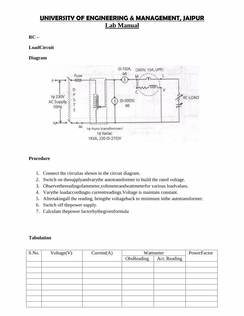
UNIVERSITY OF ENGINEERING & MANAGEMENT, JAIPURLab Manual
RC –
LoadCircuit
Diagram
Procedure
1. Connect the circuitas shown in the circuit diagram.2. Switch on thesupplyandvarythe autotransformer to build the rated voltage.3. Observethereadingofammeter,voltmeterandwattmeterfor various loadvalues.4. Varythe loadaccordingto currentreadings.Voltage is maintain constant.5. Aftertakingall the reading, bringthe voltageback to minimum inthe autotransformer.6. Switch off thepower supply.7. Calculate thepower factorbythegivenformula
Tabulation
S.No. Voltage(V) Current(A) Wattmeter PowerFactorObsReading Act. Reading

UNIVERSITY OF ENGINEERING & MANAGEMENT, JAIPURLab Manual
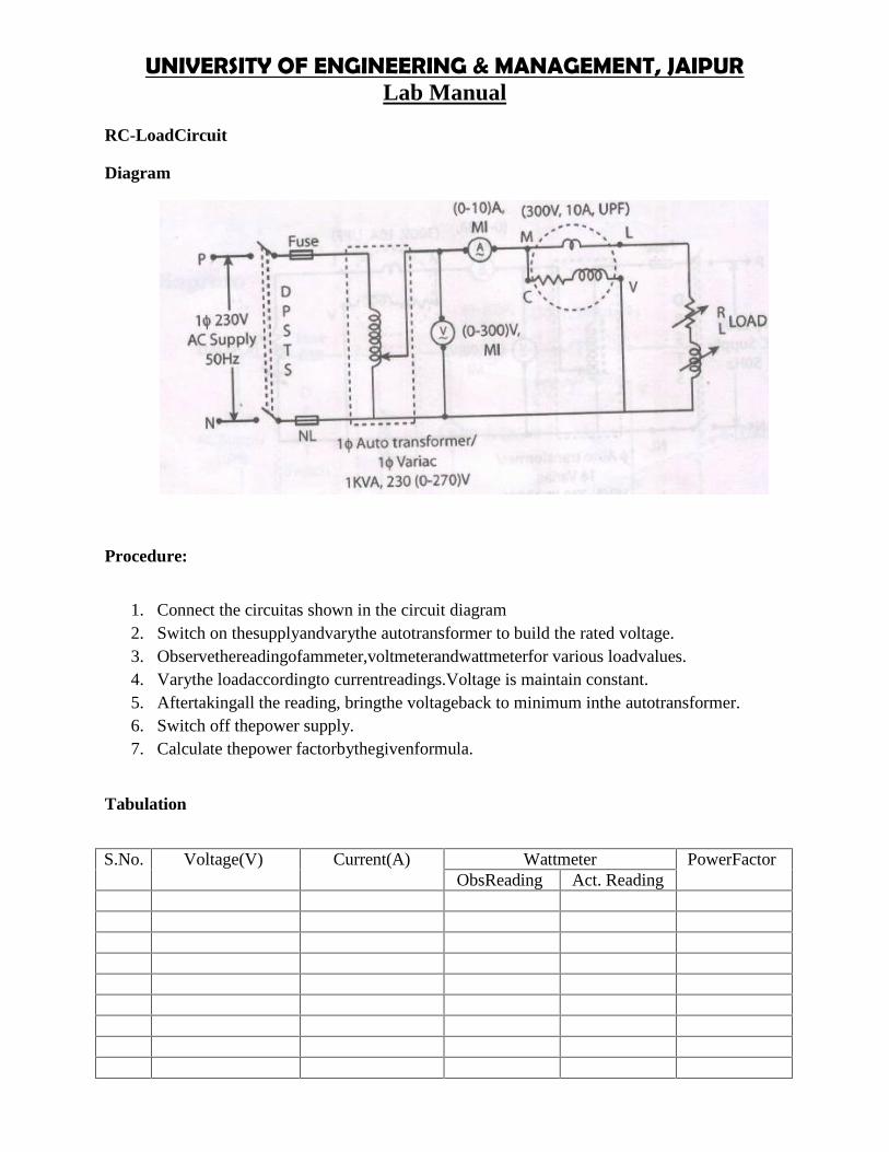
UNIVERSITY OF ENGINEERING & MANAGEMENT, JAIPURLab Manual
RC-LoadCircuit
Diagram
Procedure:
1. Connect the circuitas shown in the circuit diagram2. Switch on thesupplyandvarythe autotransformer to build the rated voltage.3. Observethereadingofammeter,voltmeterandwattmeterfor various loadvalues.4. Varythe loadaccordingto currentreadings.Voltage is maintain constant.5. Aftertakingall the reading, bringthe voltageback to minimum inthe autotransformer.6. Switch off thepower supply.7. Calculate thepower factorbythegivenformula.
Tabulation
S.No. Voltage(V) Current(A) Wattmeter PowerFactorObsReading Act. Reading
UNIVERSITY OF ENGINEERING & MANAGEMENT, JAIPURLab Manual
Result:
Thustheelectricalquantities–voltage,currentandpoweraremeasuredforRLCloadandcorrespondingpower factoris calculated.
UNIVERSITY OF ENGINEERING AND MANAGEMENT, JAIPURLab Manual
Exercise No. 5: Study of ETAP.
Aim: To study Electrical Power System design tool and use it for various design calculations andestimate.
Studies shall be performed using the latest version of approved software:ETAP (Developed by ETAP / Operation Technology, Inc.)Approved equal C. Software Program RequirementsSoftware shall comply with IEEE 399, IEEE 141, IEEE 242, IEEE 1015, IEEE 1584.
To gather and tabulate the following input data to support the power systems study:1. Product Data for overcurrent protective devices involved in overcurrent protective device
coordination studies. Use equipment designation tags that are consistent with electricaldistribution system diagrams, overcurrent protective device submittals, input and outputdata, and recommended device settings.2. Maximum fault contribution or Impedance of utility service entrance3. Electrical Distribution System Diagram: In hard-copy and electronic-copy formats,showing the following: a. Circuit-breaker and fuse-current ratings and types b. Generatorkilovolt amperes, size, voltage, and source impedance c. Cables: Indicate conduit material,sizes of conductors, conductor material, insulation, and length d. Motor horsepower andcode letter designation according to NEMA MG 14. Data sheets to supplement electrical distribution system diagram, crossreferenced with tagnumbers on diagram, showing the following: a. Special load considerations, includingstarting inrush currents and frequent starting and stopping b. Transformer characteristics,including primary protective device, magnetic inrush current, and overload capability c.Motor full-load current, locked rotor current, service factor, starting time, type of start, andthermal-damage curve d. Generator thermal-damage curve e. Ratings, types, and settings ofutility company's overcurrent protective devices f. Special overcurrent protective devicesettings or types stipulated by utility company g. Time-current-characteristic curves ofdevices indicated to be coordinated.Manufacturer, frame size, interrupting rating in amperes rms symmetrical, ampere or currentsensor rating, long-time adjustment range, short-time adjustment range, and instantaneousadjustment range for circuit breakers i. Manufacturer and type, ampere-tap adjustmentrange, time-delay adjustment range, instantaneous attachment adjustment range, and currenttransformer ratio for overcurrent relays j. Panelboards, switchboards, motor-control centerampacity, and interrupting rating in amperes rms symmetrical B. Software shall have theability to utilize typical data such as %Z, X/R ratios for transformers, etc. in case thesevalues cannot be ascertained from existing documentation and/or field data collection. C.Various system operating configurations of the system including status of switching devicesand load status (continuous, intermittent, spare), etc. shall be modeled as part of the projectdatabase using a configuration management tool. D. Study related scenarios including datarevisions, engineering properties, study solution parameters & network topology shall besetup. In the event of system changes, these scenarios may be utilized by Company at a laterdate to re-run the studies.
UNIVERSITY OF ENGINEERING & MANAGEMENT, JAIPURCourse Description
Title of Course: Seminar on Industrial Training Course Code: EE781L-T –P Scheme: 0-0-3 Course Credits: 2
Course Description & Objectives:
1. Understand the history of medical research and bioethics related to the HeLa cells. Understandthe diverse social and economic, racial and gender contexts within which Henrietta Lacks livedand died. Understand the themes of this seminar. Appreciate the legacy and implications of thesemedical, ethical and social understandings on today’s society.
2. Identify, understand and discuss current, real-world issues.
3. Distinguish and integrate differing forms of knowledge and academic disciplinary approaches(e.g., humanities and sciences) with that of the student’s own academic discipline (e.g., inagriculture, architecture, art, business, economics, education, engineering, natural resources, etc.).And apply a multidisciplinary strategy to address current, real-world issues.
4. Improve oral and written communication skills.
5. Explore an appreciation of the self in relation to its larger diverse social and academic contexts.
6. Apply principles of ethics and respect in interaction with others.
Course Outcomes:
After the completion of this course, the student should be able to:
1. Learn and integrate. Through independent learning and collaborative study, attain, use,and develop knowledge in the arts, humanities, sciences, and social sciences, with disciplinaryspecialization and the ability to integrate information across disciplines.
2. Use multiple thinking strategies to examine real-world issues, explore creativeavenues of expression, solve problems, and make consequential decisions
3. Learn and integrate. Communicate. Acquire, articulate, create and convey intendedmeaning using verbal and non-verbal method of communication that demonstratesrespect and understanding in a complex society.
4. Use multiple thinking strategies to examine real-world issues, explore creativeavenues of expression, solve problems, and make consequential decisions.
5. Clarify purpose and perspective. Explore one’s life purpose and meaning throughtransformational experiences that foster an understanding ofself, relationships, and diverseglobal perspectives.

UNIVERSITY OF ENGINEERING & MANAGEMENT, JAIPURCourse Description
6. ractice citizenship. Apply principles of ethical leadership, collaborative engagement, sociallyresponsible behavior, respect for diversity in an interdependent world, and a service-orientedcommitment to advance and sustain local and global communities.
UNIVERSITY OF ENGINEERING & MANAGEMENT, JAIPURCourse Description
Title of Course: Project Part- I Course Code: EE782L-T –P Scheme: 6P Course Credits: 4
Project: an activity where the participants have some degree of choice in the outcome. The resultis complete and functional, that is, it has a beginning, middle and end. Usually, it spans multiplelab periods and requires work outside scheduled lab periods. Since there are choices inimplementation, design is inherently a component of a project. A project is inherently differentfrom an analysis or exercise, in which the solution has a predictable form. Projects span a widevariety of possibilities: design and build, identify a system, do a forensic analysis, evaluate aproduct or assess some environmental situation.
Program Objective 1Graduates shall make their way to the society with proper scientific and technical knowledge inmechanical engineering.
Program Objective 2Graduates shall work in design and analysis of mechanical systems with strong fundamentals andmethods of synthesis.
Program Objective 3Graduates shall adapt to the rapidly changing environment in the areas of mechanicalengineering and scale new heights in their profession through lifelong learning.
Program Objective 4Graduates shall excel in career by their ability to work and communicate effectively as a teammember and/or leader to complete the task with minimal resources, meeting deadlines.
Program Outcomes:
1. Ability to apply knowledge of mathematics, science and mechanical engineeringfundamentals for solving problems.
2. Ability to Identify, formulate and analyze mechanical engineering problems arriving atmeaningful conclusions involving mathematical inferences.
3. Ability to design and develop mechanical components and processes to meet desiredneeds considering public health, safety, cultural, social, and environmental aspects.
4. Ability to understand and investigate complex mechanical engineering problemsexperimentally.
5. Ability to apply modern engineering tools, techniques and resources to solve complexmechanical engineering activities with an understanding of the limitations.
6. Ability to understand the effect of mechanical engineering solutions on legal, cultural,social, public health and safety aspects./li>

UNIVERSITY OF ENGINEERING & MANAGEMENT, JAIPURCourse Description
7. Ability to develop sustainable solutions and understand their impact on society andenvironment.
8. Ability to apply ethical principles to engineering practices and professionalresponsibilities.
9. Ability to function effectively as an individual and as a member or leader in diverseteams and in multidisciplinary settings.
10. Ability to comprehend, design documentation, write effective reports, make effectivepresentations to the engineering community and society at large.
11. Ability to apply knowledge of engineering and management principles to lead teams andmanage projects in multidisciplinary environments.
12. Ability to engage in independent and life-long learning in the broad context oftechnological changes and advancements.